dr. abdul ahad - abdus salam centre for physics · the ncp 5udh-2 pelletron • 5 mv terminal...
TRANSCRIPT

An Overview of 5MV An Overview of 5MV Pelletron Accelerator at Pelletron Accelerator at
NCPNCP
Dr. Abdul AhadDr. Abdul Ahad
ContentsContents
• Electrostatic Accelerators• 5UDH-2 Pelletron at NCP
– introduction– Control System– Ion Sources– RC43 Setup– RS61 Setup
• Applications (Ion Beam Analysis)
33
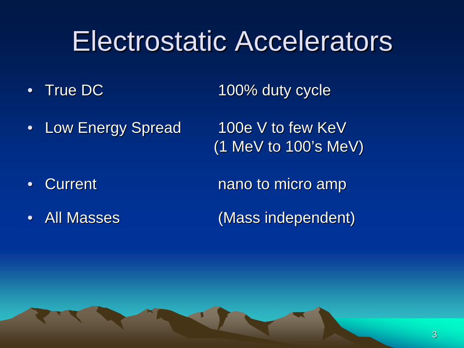
Electrostatic AcceleratorsElectrostatic Accelerators•• True DCTrue DC 100% duty cycle100% duty cycle
•• Low Energy SpreadLow Energy Spread 100e V to few KeV 100e V to few KeV (1 MeV to 100(1 MeV to 100’’s MeV)s MeV)
•• CurrentCurrent nano to micro amp nano to micro amp
•• All MassesAll Masses (Mass independent)(Mass independent)

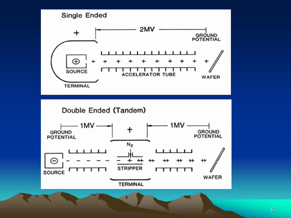
Electrostatic AcceleratorsElectrostatic Accelerators
Single Ended
• Higher Currents• Ne, Ar, Xe• Less energy spread (microprobes)
Electrostatic AcceleratorsElectrostatic Accelerators
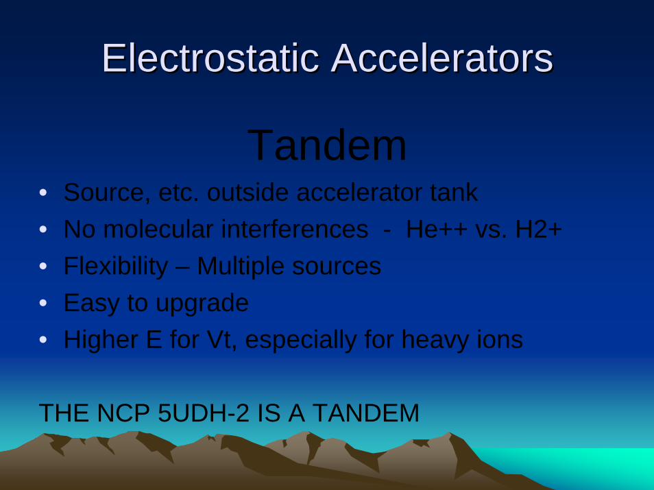
Tandem• Source, etc. outside accelerator tank• No molecular interferences - He++ vs. H2+• Flexibility – Multiple sources• Easy to upgrade• Higher E for Vt, especially for heavy ions
THE NCP 5UDH-2 IS A TANDEM
66
Electrostatic AcceleratorsElectrostatic Accelerators
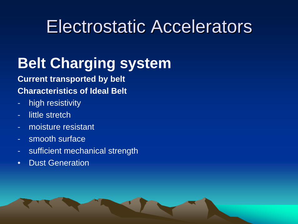
Belt Charging systemCurrent transported by beltCharacteristics of Ideal Belt- high resistivity - little stretch- moisture resistant- smooth surface- sufficient mechanical strength• Dust Generation

Electrostatic AcceleratorsElectrostatic Accelerators

Electrostatic AcceleratorsElectrostatic Accelerators
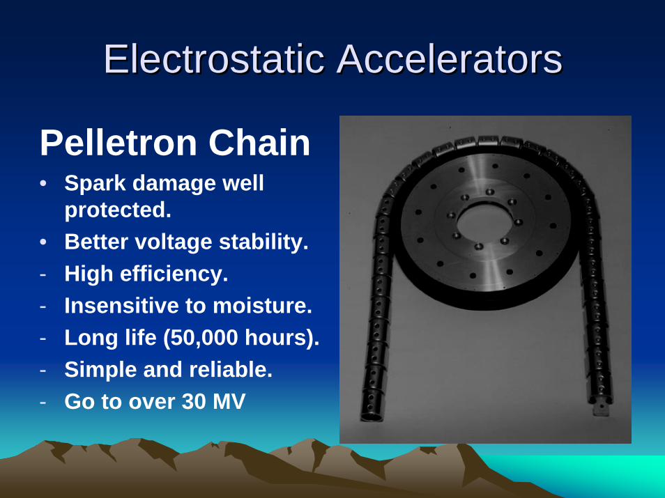
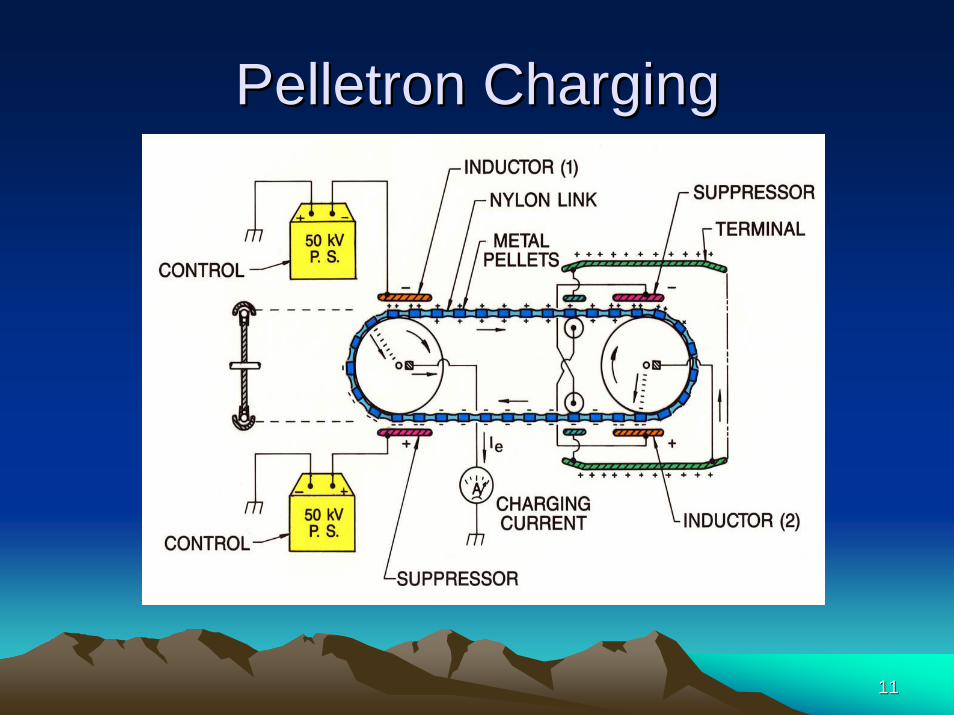
• Pelletron charging System By NEC (1960)• Metal cylinders with rounded ends joined by nylon • Move at at bout 15 m/s• Delivers charging currents of 100 - 200 µA • motors are supported on movable platforms which
are counterweighted, automatically providing proper chain tension
Electrostatic AcceleratorsElectrostatic Accelerators
Pelletron Chain• Spark damage well
protected.• Better voltage stability.- High efficiency.- Insensitive to moisture.- Long life (50,000 hours).- Simple and reliable.- Go to over 30 MV
1111
Pelletron ChargingPelletron Charging

1212

1313
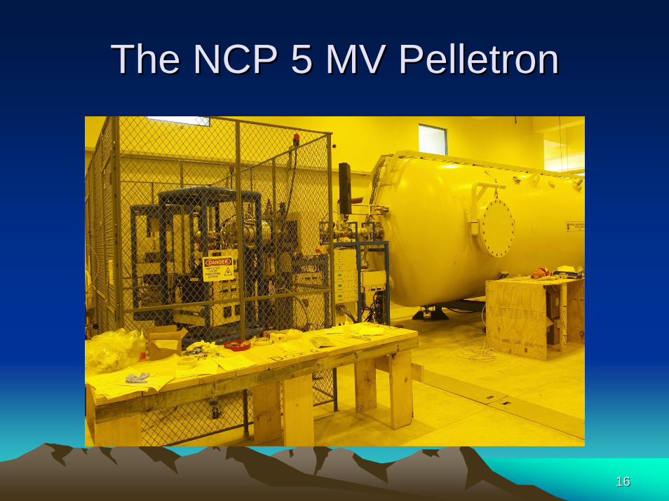
The NCP 5UDHThe NCP 5UDH--2 PELLETRON2 PELLETRON
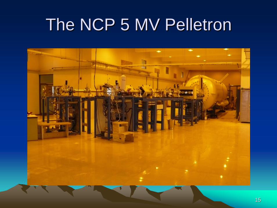
•• 5 MV Terminal Voltage5 MV Terminal Voltage•• Dual Ion Sources Dual Ion Sources
–– SNICS II for wide range of light and heavy ionsSNICS II for wide range of light and heavy ions–– RFRF--Charge Exchange for He Charge Exchange for He
•• Beam currents Beam currents –– 5 5 –– 10 microamps for most probable charge states, 10 microamps for most probable charge states, –– 100's of pA for high charge state heavy ions100's of pA for high charge state heavy ions
•• Energies Energies –– 10 MeV for Protons, 15 MeV for He++10 MeV for Protons, 15 MeV for He++–– Useful currents for heavy ions to over 50 MeVUseful currents for heavy ions to over 50 MeV
•• 15 degree beamline for Materials Analysis15 degree beamline for Materials Analysis•• 30 degree beamline for Ion Scattering/Nuclear Physics 30 degree beamline for Ion Scattering/Nuclear Physics

The NCP 5 MV PelletronThe NCP 5 MV Pelletron
1515
The NCP 5 MV PelletronThe NCP 5 MV Pelletron
1616
The NCP 5 MV PelletronThe NCP 5 MV Pelletron

1717
The NCP 5 MV ColumnThe NCP 5 MV Column

1818
Control systemControl system
Control & Data Acquisition
• LINUX based computer user interface
• MCA CARDS for data acquisition

Control systemControl system
2020
Beam EnergyBeam Energy
•• Tandem accelerates the negative ion to the Tandem accelerates the negative ion to the positive terminal positive terminal
•• Then strips to many charge states, QThen strips to many charge states, Q•• Each state picks up Q x MV Each state picks up Q x MV •• Total Energy = (Q+1)MVTotal Energy = (Q+1)MV•• Charge state probability depends on terminal Charge state probability depends on terminal
voltage, ion mass, and strippervoltage, ion mass, and stripper
2121
Beam CurrentsBeam Currents
•• The next slide shows the wide variety of The next slide shows the wide variety of beam energies and currents from a beam energies and currents from a tandem at 3MVtandem at 3MV
•• Higher energies are possible in the 5UDHHigher energies are possible in the 5UDH

2222

2323
ION SOURCESION SOURCES
•• The purpose of the ions sources are to The purpose of the ions sources are to produce either positive or negative ions produce either positive or negative ions from neutral atoms of elements of interest.from neutral atoms of elements of interest.
•• the ions beams are injected to the the ions beams are injected to the accelerator tube for gaining high energy.accelerator tube for gaining high energy.
2424
SNICS II Ion SourceSNICS II Ion Source
•• ““Source of Negative Ions by Cesium Source of Negative Ions by Cesium SputteringSputtering”” from solid materials.from solid materials.
•• Cs ions from hot Cs ions from hot ““ionizerionizer”” surface are surface are accelerated to the cathode. accelerated to the cathode.
•• Cathode contains element (s) for beams. Cathode contains element (s) for beams. •• Simple operation; rapid cathode change.Simple operation; rapid cathode change.•• Currents up to 100's of micoramps Currents up to 100's of micoramps
depending on material.depending on material.

SNICS II Ion SourcesSNICS II Ion Sources

2626
Principle Of OperationPrinciple Of Operation
•• Cs vapor comes from the cesium oven into Cs vapor comes from the cesium oven into an enclosed area between the cooled an enclosed area between the cooled cathode and the heated ionizing surface.cathode and the heated ionizing surface.
•• Some of the cesium condenses on the Some of the cesium condenses on the front of the cathode and some of the front of the cathode and some of the cesium is ionized by the hot surface. cesium is ionized by the hot surface.

2727
Cont..Cont..
•• The ionized cesium accelerates towards the The ionized cesium accelerates towards the cathode, sputtering particles from the cathode cathode, sputtering particles from the cathode through the condensed cesium layer. through the condensed cesium layer.
•• Some materials will preferentially sputter Some materials will preferentially sputter negative ions. negative ions.
•• Other materials will preferentially sputter neutral Other materials will preferentially sputter neutral or positive particles which pick up electrons as or positive particles which pick up electrons as they pass through the condensed cesium layer, they pass through the condensed cesium layer, producing negative ions. producing negative ions.

2828
SNICS II Ion SourcesSNICS II Ion Sources

Alphatross Ion SourcesAlphatross Ion Sources
3030
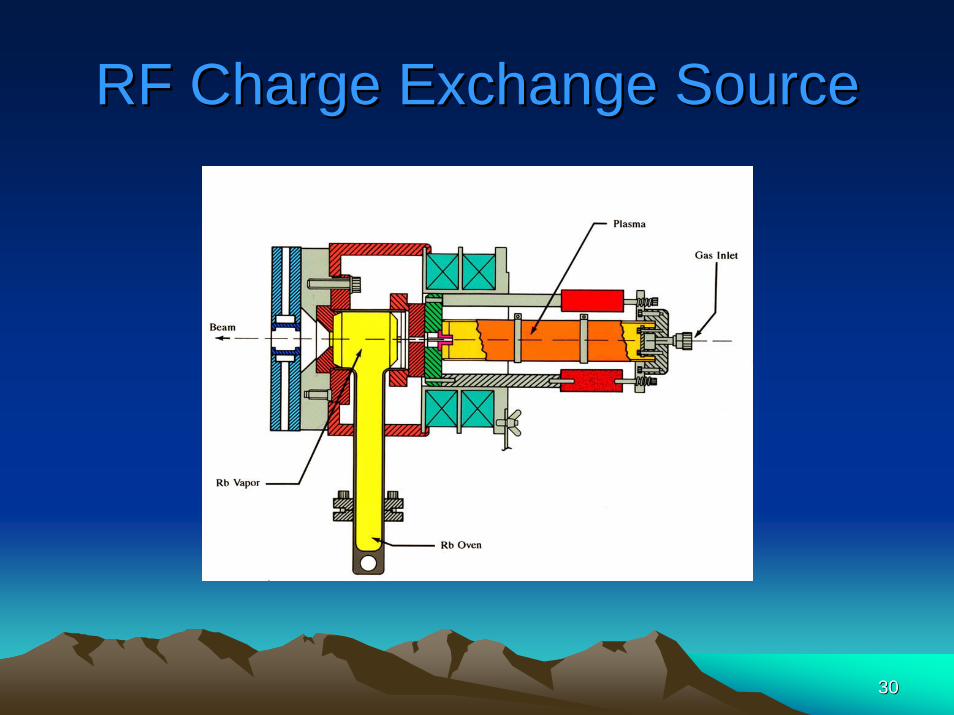
RF Charge Exchange SourceRF Charge Exchange Source

3131
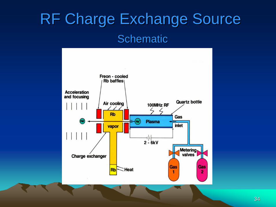
Operation PrincipleOperation Principle
•• There are two main components in this device. There are two main components in this device. The first one is the radio frequency positive ion The first one is the radio frequency positive ion source. source.
•• Helium gas is bled into a quartz discharge bottle Helium gas is bled into a quartz discharge bottle through a metering valve to maintain a pressure through a metering valve to maintain a pressure of 10of 10--50 millitorr.50 millitorr.
•• An RF oscillator induces a plasma in the bottle An RF oscillator induces a plasma in the bottle which is intensified by the solenoid magnet.which is intensified by the solenoid magnet.

3232
Cont..Cont..
•• A DC potential is applied across the A DC potential is applied across the plasma by probe power supply. plasma by probe power supply.
•• This potential extracts ions from the This potential extracts ions from the plasma and accelerates them through the plasma and accelerates them through the Ta exit canal. Ta exit canal.
•• Then they enter the charge exchange Then they enter the charge exchange chamber.chamber.
3333
Cont..Cont..
•• The charge exchange is the second main The charge exchange is the second main component of the Alphatross. component of the Alphatross.
•• In it HeIn it He+ + ions are neutralized by Rb vapor. ions are neutralized by Rb vapor. •• A few He atoms then undergo a 2A few He atoms then undergo a 2ndnd charge charge
exchange reaction and become negative exchange reaction and become negative He ions. He ions.
3434
RF Charge Exchange SourceRF Charge Exchange SourceSchematicSchematic
3535
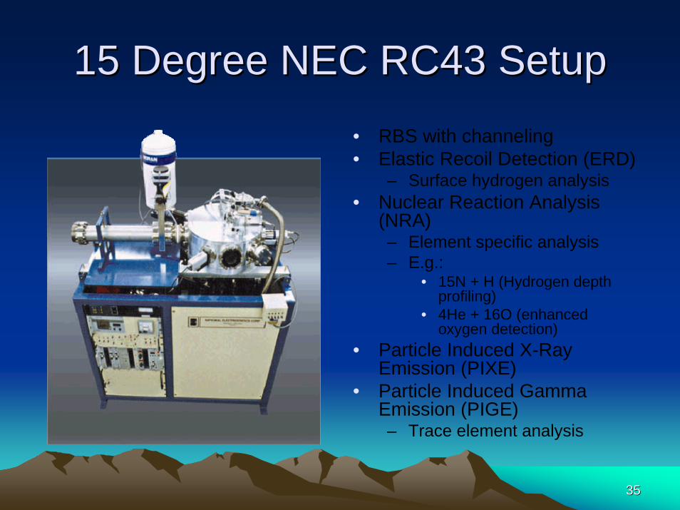
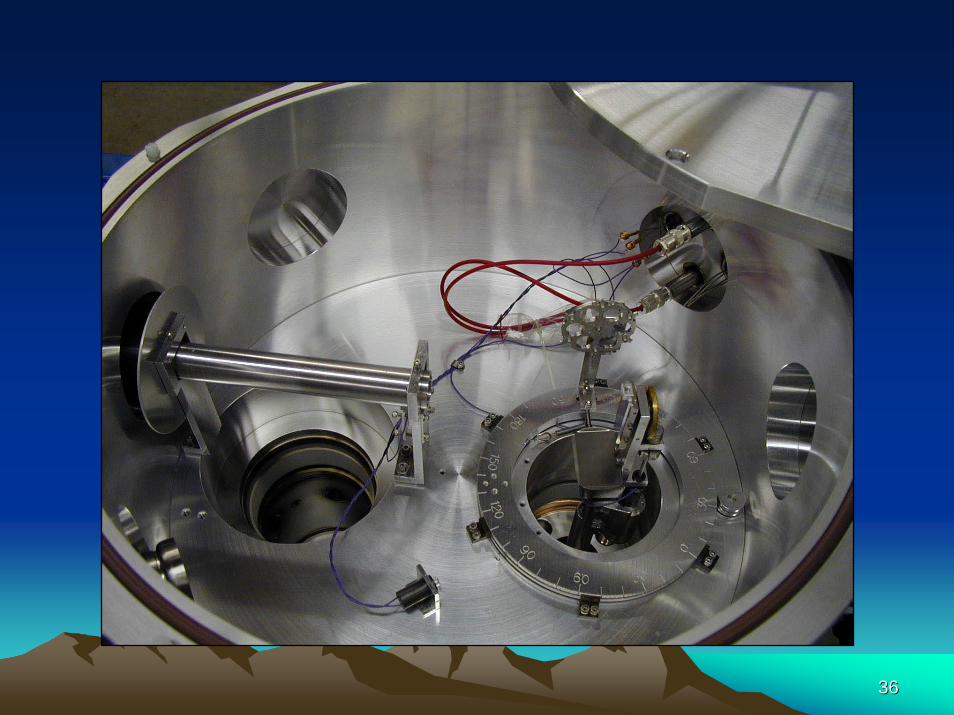
15 Degree NEC RC43 Setup15 Degree NEC RC43 Setup• RBS with channeling• Elastic Recoil Detection (ERD)
– Surface hydrogen analysis• Nuclear Reaction Analysis
(NRA) – Element specific analysis– E.g.:
• 15N + H (Hydrogen depth profiling)
• 4He + 16O (enhanced oxygen detection)
• Particle Induced X-Ray Emission (PIXE)
• Particle Induced Gamma Emission (PIGE) – Trace element analysis
3636
3737
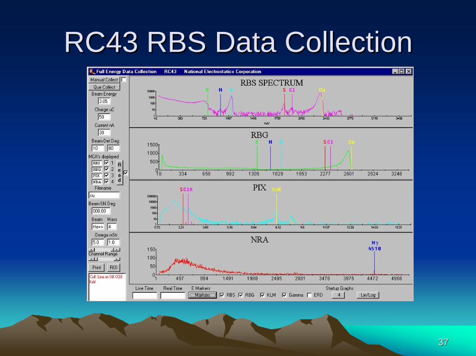
RC43 RBS Data CollectionRC43 RBS Data Collection

3838
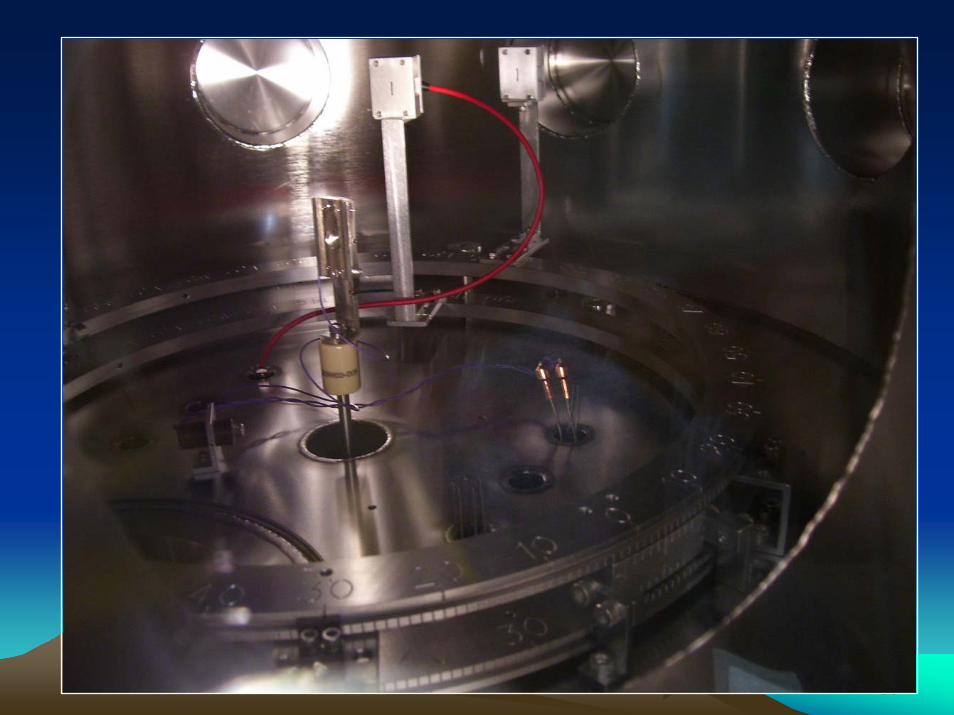
NEC RS61 Scattering SystemNEC RS61 Scattering System• Ion Scattering Studies
• Nuclear Physics
• Atomic Physics
• Ion Implantation
• Radiation Damage Studies
3939
4040
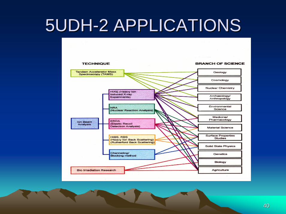
5UDH5UDH--2 APPLICATIONS2 APPLICATIONS

Ion Beam AnalysisIon Beam Analysis

Ion Beam AnalysisIon Beam Analysis• The 5UDH-2 accelerator systems is equipped for materials analysis with ion
beams at MeV energies, using one or more of the following analytic techniques:
• RBS (Rutherford Backscattering): for elemental depth profiling
• Channeling: for measuring crystalline perfection and impurities in crystals
• ERD (Elastic Recoil Detection): primarily for Hydrogen depth profiling
• NRA (Nuclear Reaction Analysis): for measuring selected isotopes with enhanced sensitivity
• PIXE (particle Induced X-Ray Emission): for trace element analysis

Rutherford Back Scattering (RBS)Rutherford Back Scattering (RBS)
• Rutherford scattering is simple, central force, elastic scattering.
• The effects of nuclear reactions are avoided by operating at beam energies below the Coulomb barrier.
• This is basically billiard ball scattering. Kinematices and absolute cross sections can be calculated directly from first principles.
Rutherford Back Scattering (RBS)Rutherford Back Scattering (RBS)
• The thickness of the surface layer is determined from the energy width of the surface peak, using standard dE/dx energy loss calculations.
• The elemental concentration as a function of depth can also be determined from the number of counts as a function of energy for both the surface layer and the substrate.
• Channeling Measures crystal perfection, which is especially valuable in silicon technologies.
PIXEPIXE• Non-destructive, quantitative analysis of heavier
elements.• Generally used for trace element analysis 1-100ppm. • Identify high-Z elements (11<Z<92).• Identification of elements that RBS cannot resolve. • Composition of Magnetic multilayers - storage media and
head structures. • Major applications include: aerosol analysis,
pigment composition of paintings, studies of artifacts, Materials science, Bio sciences and Medical applications.
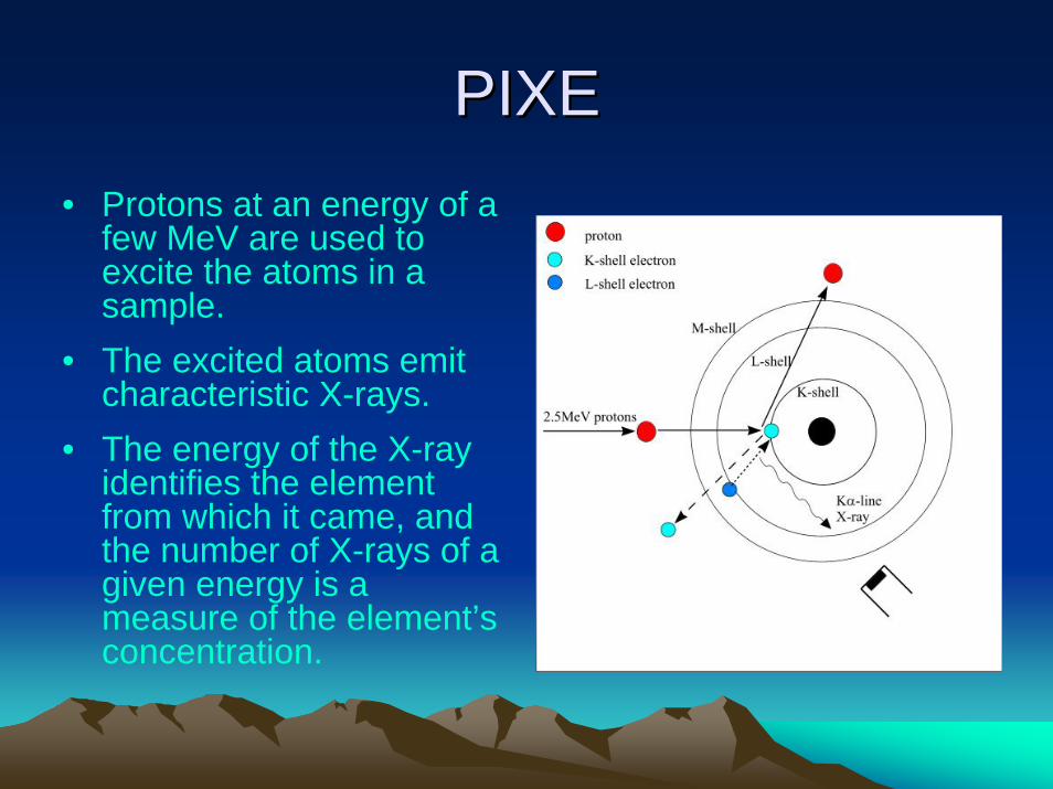
PIXEPIXE• Protons at an energy of a
few MeV are used to excite the atoms in a sample.
• The excited atoms emit characteristic X-rays.
• The energy of the X-ray identifies the element from which it came, and the number of X-rays of a given energy is a measure of the element’s concentration.
PIXEPIXE
• Probed depth tens of µm.• Sensitivity up to 1ppm.• Accuracy 10%.• Higher signal to background ratio as
compared to electron beam induced x-ray spectroscopy.
• Low velocities changes as compared to electron, hence no bremsstrahlung.
• PIXE is 100 times more sensitive than EDX.

4848
ThanksThanks
4949
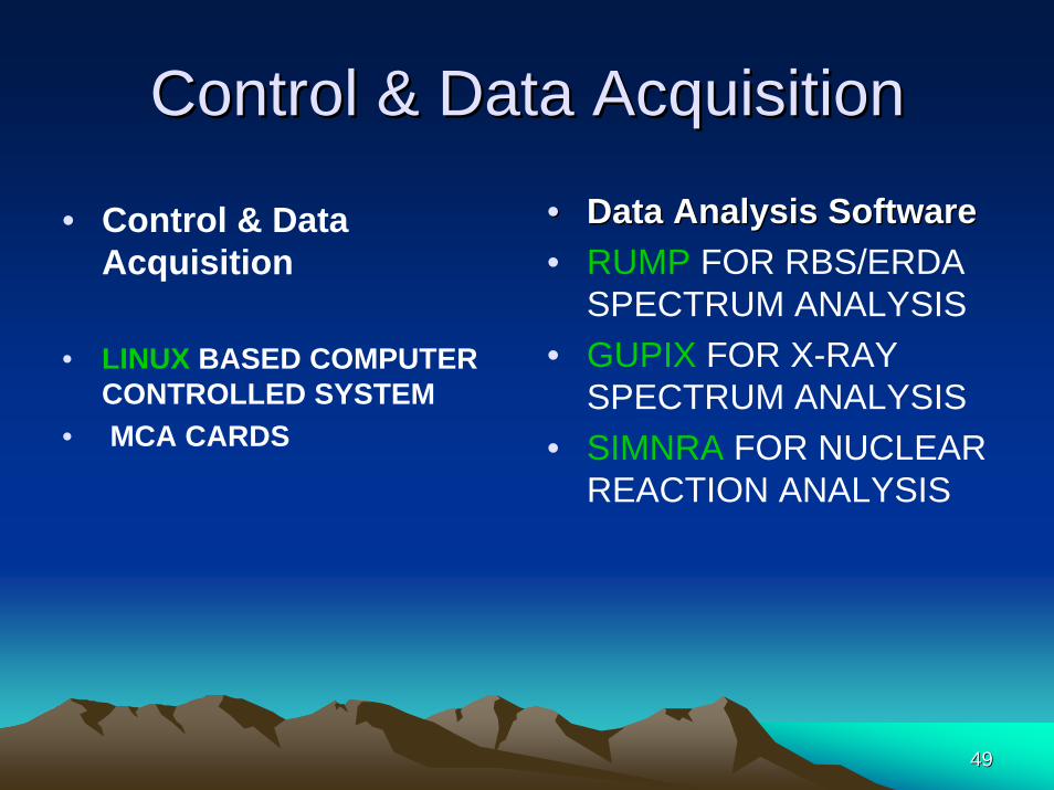
Control & Data AcquisitionControl & Data Acquisition
• Control & Data Acquisition
• LINUX BASED COMPUTER CONTROLLED SYSTEM
• MCA CARDS
•• Data Analysis SoftwareData Analysis Software• RUMP FOR RBS/ERDA
SPECTRUM ANALYSIS • GUPIX FOR X-RAY
SPECTRUM ANALYSIS• SIMNRA FOR NUCLEAR
REACTION ANALYSIS

Ion Beam AnalysisIon Beam Analysis
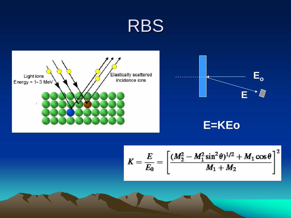
RBSRBS
Eo
E
E=KEo