dr. dóra maros institute of telecommunication Óbuda university telecommunications techniques ii....
TRANSCRIPT
Dr. Dóra MarosInstitute of Telecommunication
Óbuda University
Telecommunications Techniques II.Source Coding (speech)
Error detection and Error correction
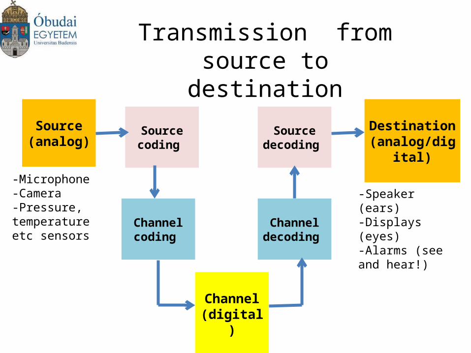
Transmission from source to destination
Source (analog)
Destination (analog/digital)
Channel (digital)
Channel coding
Channel decoding
Sourcecoding
Sourcedecoding
-Microphone-Camera-Pressure, temperature etc sensors
-Speaker (ears)-Displays (eyes)-Alarms (see and hear!)
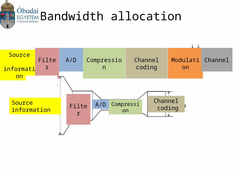
Bandwidth allocation
Source information
Source information Filter
Filter
A/D
A/D
Compression
Compression
Channel coding
Channel coding
Modulation Channel
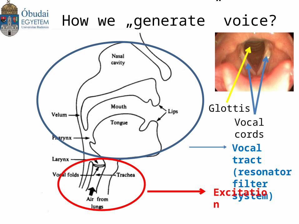
How we „generate” voice?
Vocal tract (resonator filter system)
Excitation
Vocal cordsGlottis
Characterization of Human Speech
• Frequency: 300-3400 Hz
• The charcaterization of a 20 ms duration sample does not change (excitation, filter system)
• We can find some correlations between two consecutive 20 ms samples
• Using a long time analysis we can predict the next pattern (differencial coding, eg. DPCM)
•Our brain can correct a lot of „errors”!
Classification of Speech Encoders
Waveform encoder: describes the analog signals in the time and frequency domain
Vocoders: describes the rules of phonation (how we generate the voice)
Hybrid encoders: combines good properties of two coders (low rate, good quality)
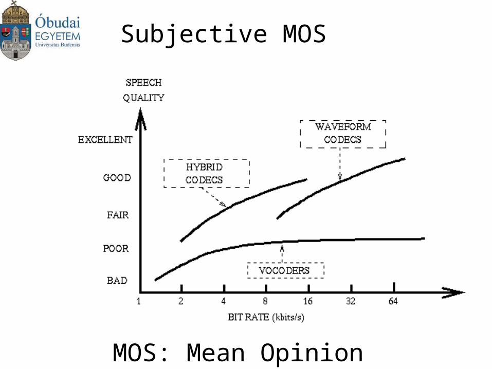
Subjective MOS
MOS: Mean Opinion Score
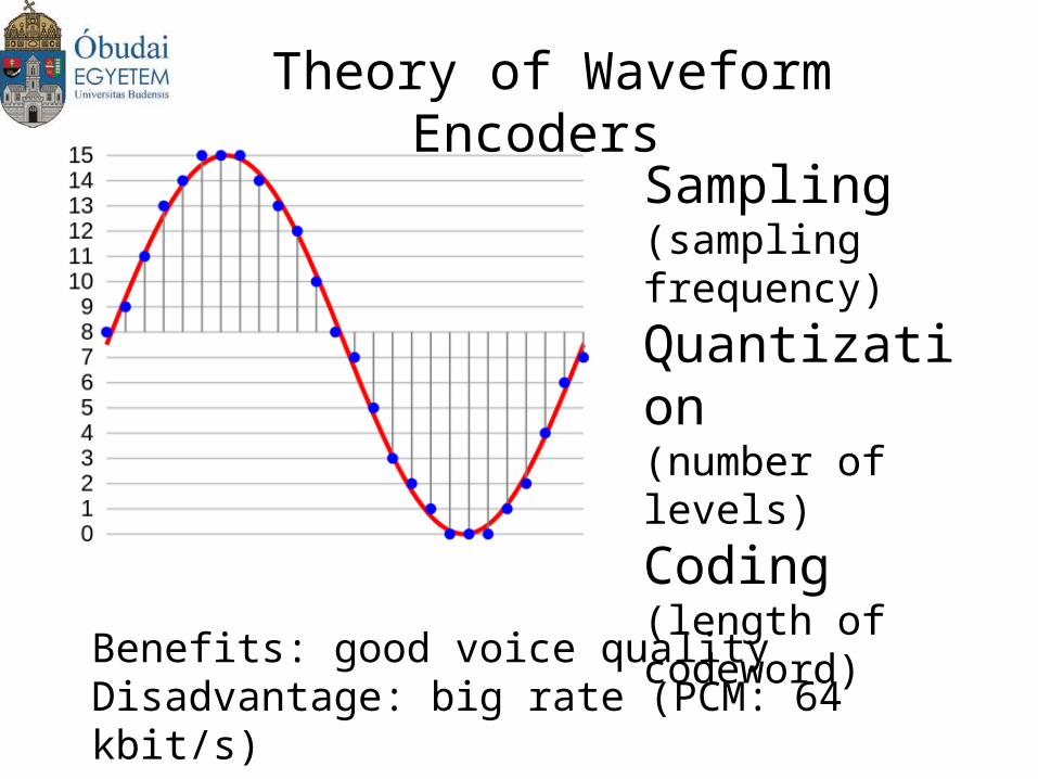
Theory of Waveform Encoders
Sampling(sampling frequency)Quantization(number of levels)Coding(length of codeword)
Benefits: good voice qualityDisadvantage: big rate (PCM: 64 kbit/s)
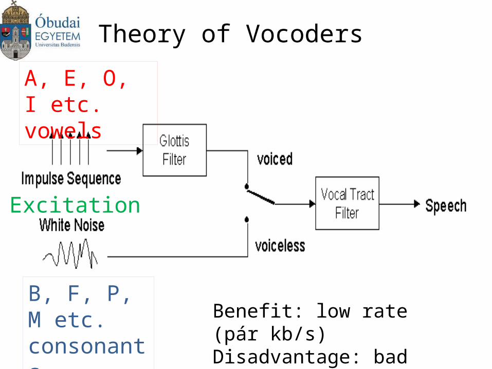
Theory of Vocoders
Benefit: low rate (pár kb/s)Disadvantage: bad quality
A, E, O, I etc.vowels
B, F, P, M etc.consonants
Excitation
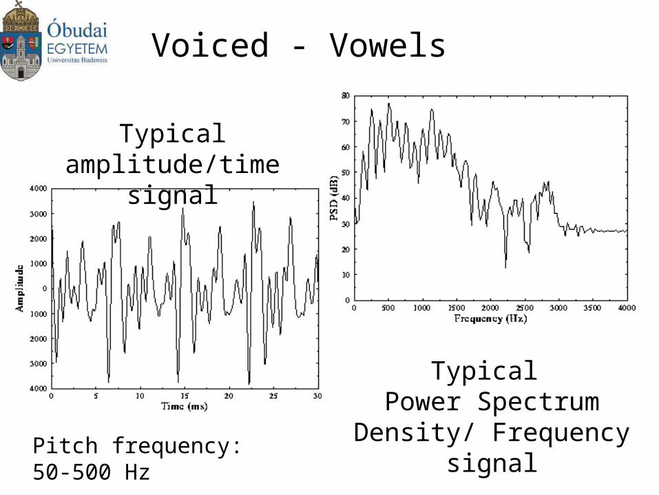
Voiced - Vowels
Typical amplitude/time signal
Typical Power Spectrum Density/
Frequency signalPitch frequency: 50-500 Hz
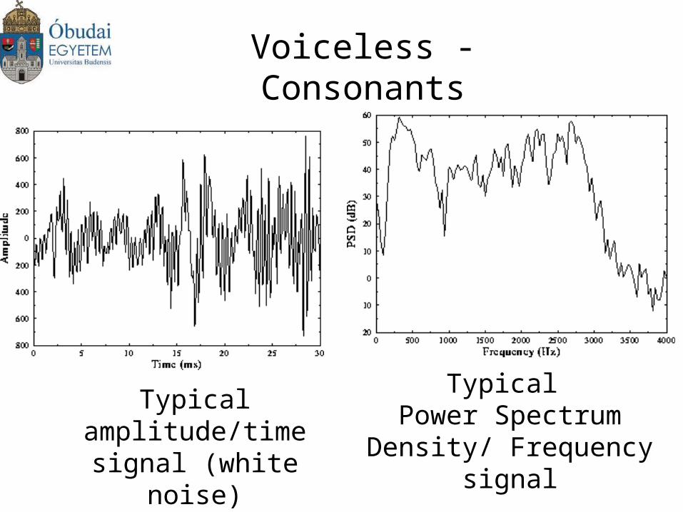
Voiceless - Consonants
Typical amplitude/time signal (white noise)
Typical Power Spectrum Density/
Frequency signal
Sub-band Coding
•Baseband is divided into sub-bands regarding PSD
•Each sub-bands are encoded separately
•Benefits: low noise sensitivity (different sampling frequencies and codeword length are used)
•Bitrate: 16-32 kbit/s
•Receiver: sub-bands are superimposed (added)
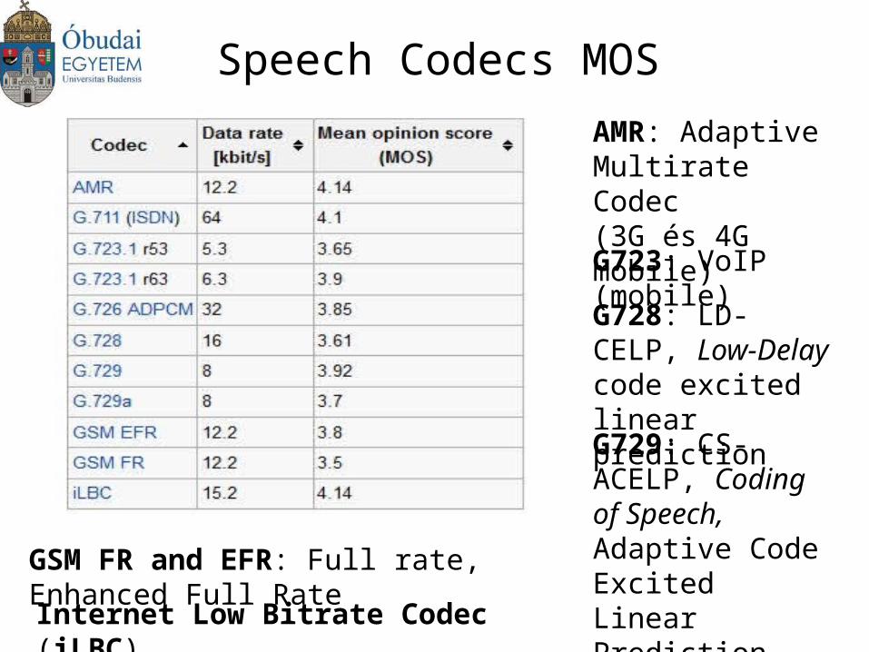
Speech Codecs MOS
AMR: Adaptive Multirate Codec(3G és 4G mobile)
G723: VoIP (mobile)
G728: LD-CELP, Low-Delay code excited linear prediction
G729: CS-ACELP, Coding of Speech, Adaptive Code Excited Linear Prediction (VoIP)
GSM FR and EFR: Full rate, Enhanced Full Rate
Internet Low Bitrate Codec (iLBC)
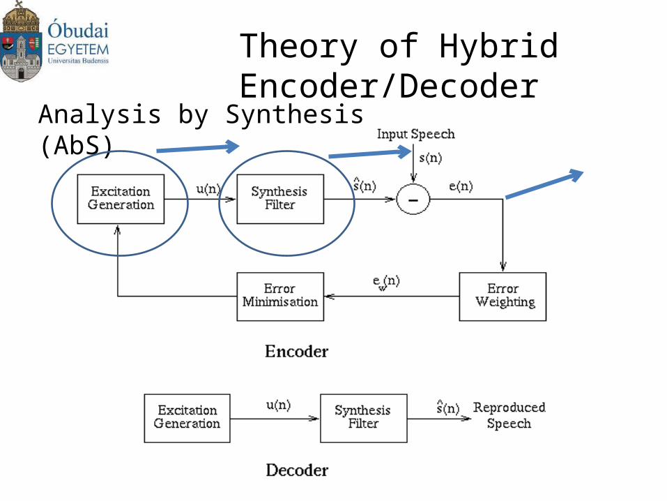
Theory of Hybrid Encoder/Decoder
Analysis by Synthesis (AbS)
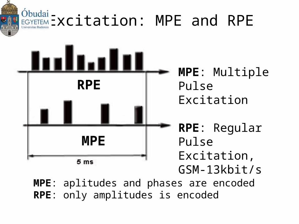
Excitation: MPE and RPE
MPE: Multiple Pulse Excitation
RPE: Regular Pulse Excitation, GSM-13kbit/s
MPE: aplitudes and phases are encodedRPE: only amplitudes is encoded
RPE
MPE
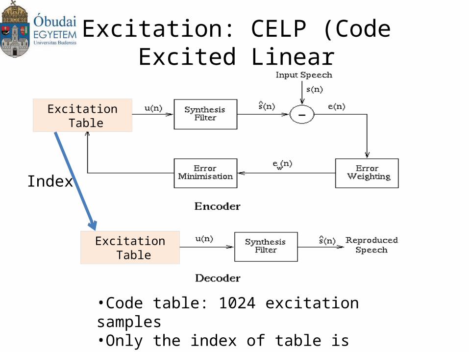
Excitation: CELP (Code Excited Linear Prediction)
•Code table: 1024 excitation samples•Only the index of table is sent!•Bitrate: 4,8-16 kbit/s
Excitation Table
Excitation Table
Index
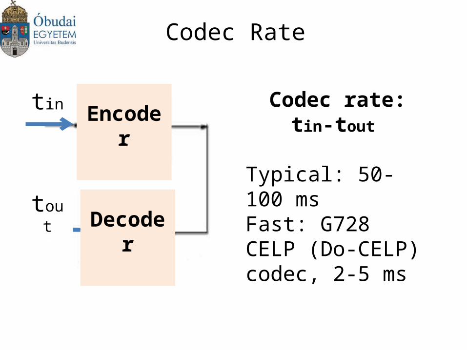
Codec Rate
Codec rate:tin-tout
Typical: 50-100 msFast: G728 CELP (Do-CELP) codec, 2-5 ms
Encoder
Decoder
tin
tout
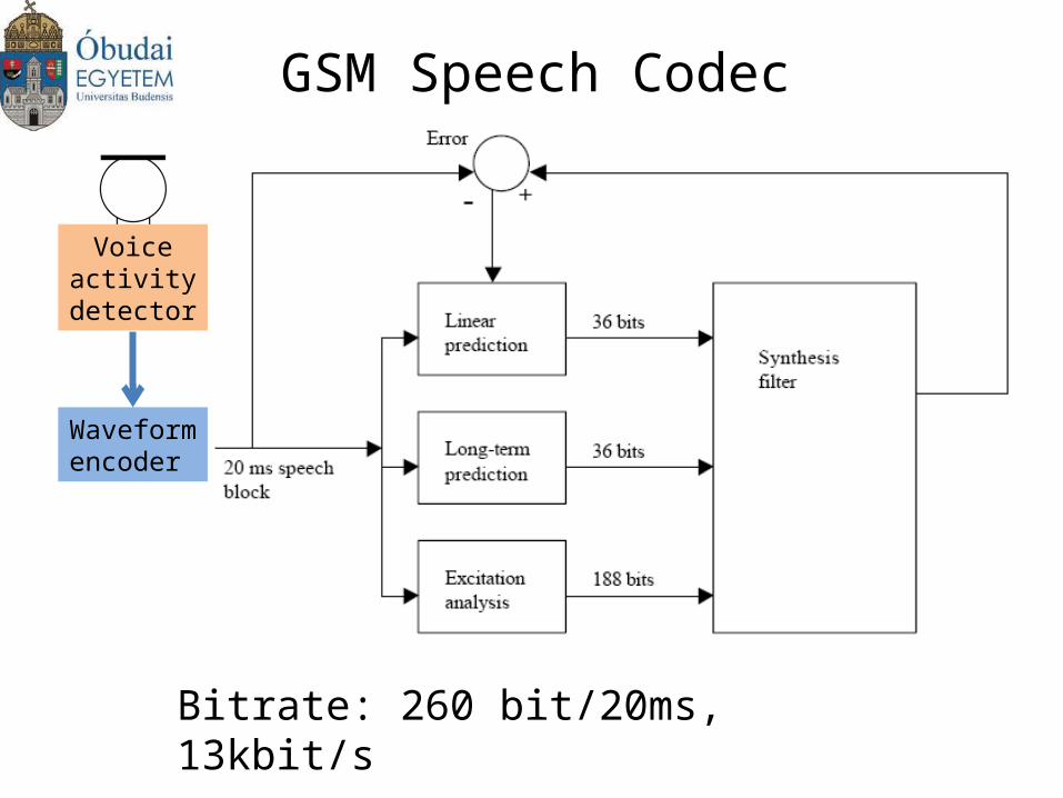
GSM Speech Codec
Bitrate: 260 bit/20ms, 13kbit/s
Waveform encoder
Voice activity detector
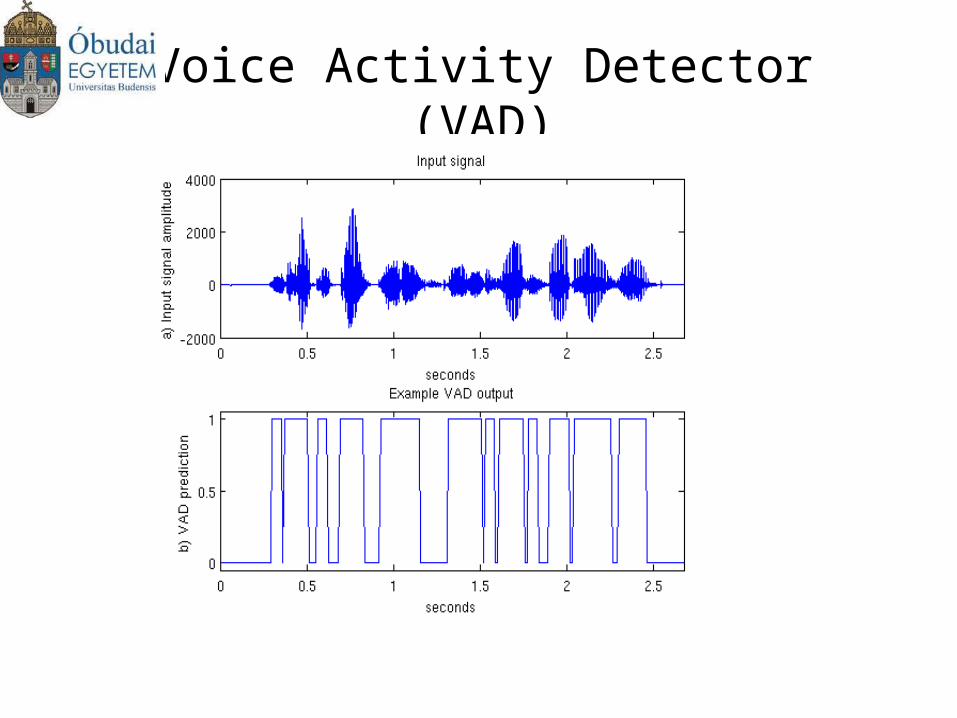
Voice Activity Detector (VAD)
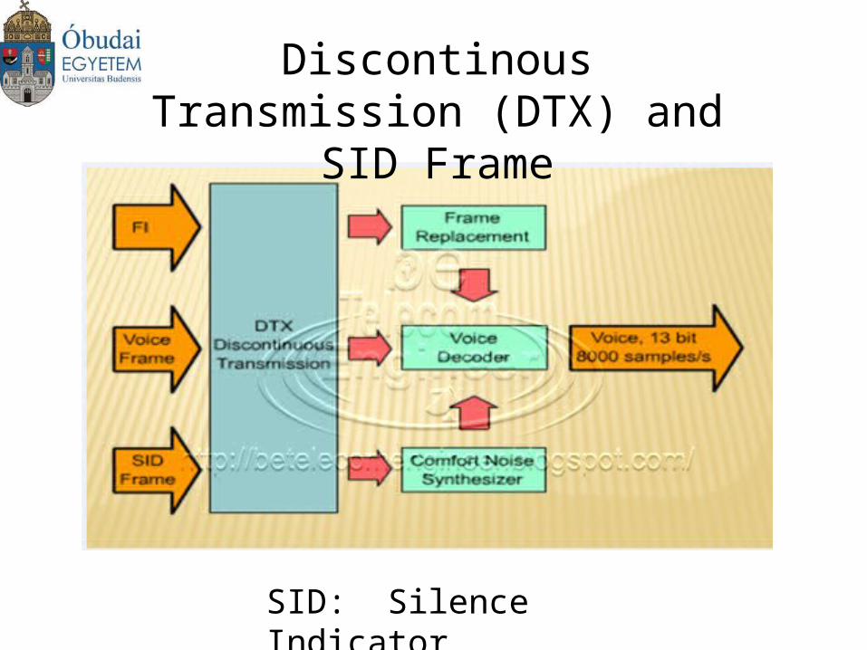
Discontinous Transmission (DTX) and SID Frame
SID: Silence Indicator
Frequency
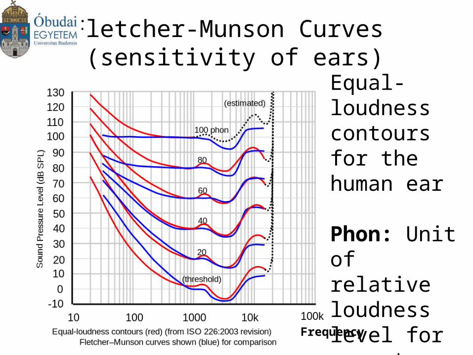
Fletcher-Munson Curves (sensitivity of ears)
Equal-loudness contours for the human ear
Phon: Unit of relative loudness level for pure tones
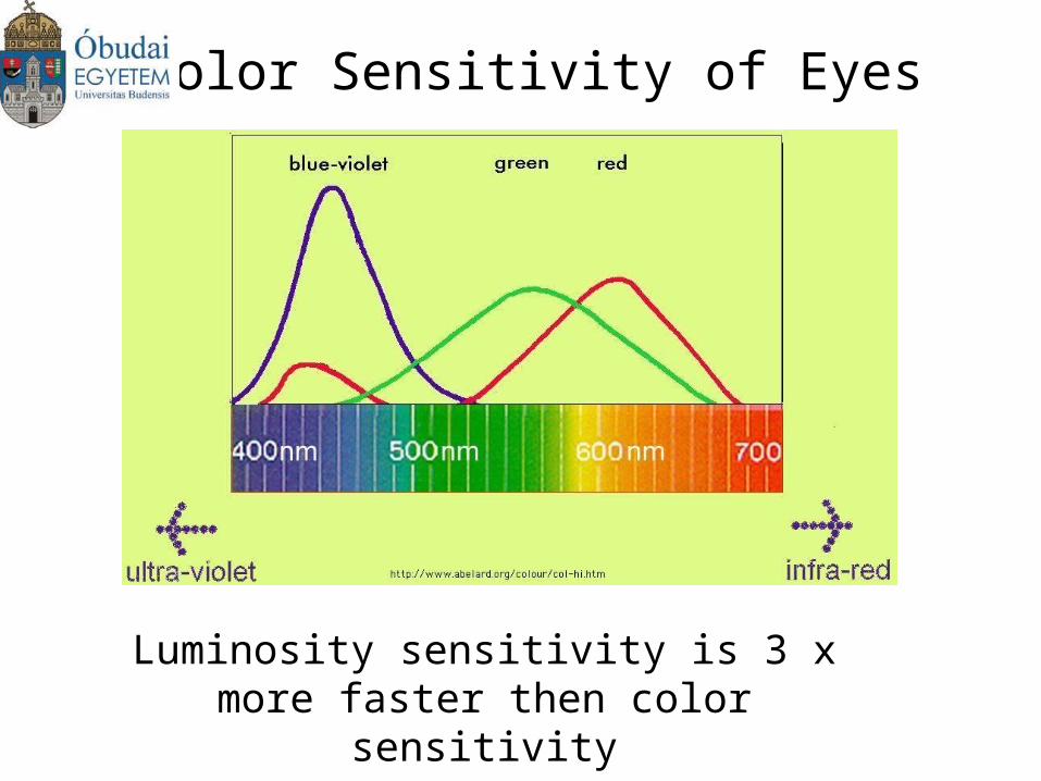
Color Sensitivity of Eyes
Luminosity sensitivity is 3 x more faster then color sensitivity
Compression of Source Information
Lossless compression: small part of information is lost
Lossy compression: huge part of information is lost
Compression Rate: original information/compressed information
image: lossless : .raw lossy: .jpeg (eg. 25/1)
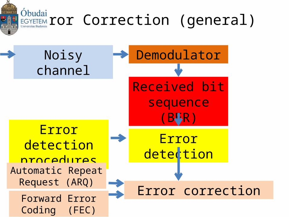
Error Correction (general)
Noisy channel Demodulator
Received bit sequence (BER)
Error detectionError detection
procedures
Error correction
Automatic Repeat Request (ARQ)
Forward Error Coding (FEC)
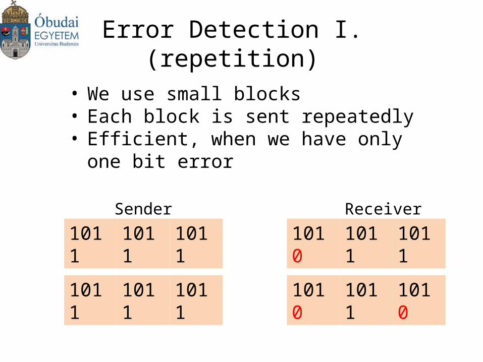
Error Detection I. (repetition)
• We use small blocks• Each block is sent repeatedly• Efficient, when we have only one bit error
1011 1011 1011 1010 1011 1011Sender Receiver
1011 1011 1011 1010 1011 1010
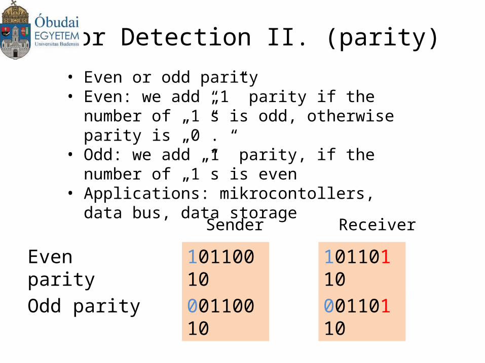
• Even or odd parity• Even: we add „1” parity if the number of „1”s is
odd, otherwise parity is „0”.• Odd: we add „1” parity, if the number of „1”s is
even• Applications: mikrocontollers, data bus, data
storage
10110010
00110010
Even parity
Odd parity
Sender Receiver
10110110
00110110
Error Detection II. (parity)
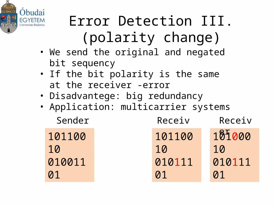
Error Detection III. (polarity change)
10110010
01001101
Sender Receiver
10110010
01011101
• We send the original and negated bit sequency• If the bit polarity is the same at the receiver -
error• Disadvantege: big redundancy• Application: multicarrier systems
01011101
10100010
Receiver
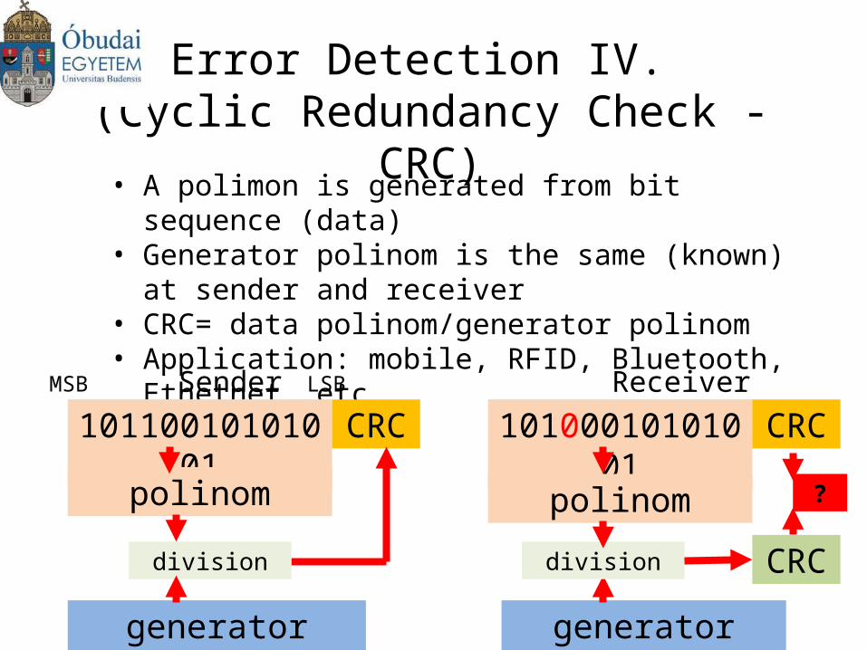
Error Detection IV. (Cyclic Redundancy Check -CRC)
• A polimon is generated from bit sequence (data) • Generator polinom is the same (known) at sender and
receiver• CRC= data polinom/generator polinom• Application: mobile, RFID, Bluetooth, Ethetnet..etc
10110010101001Sender Receiver
CRC 10100010101001 CRC
polinom
generator polinom generator polinom
division
polinom
division CRC
?
MSB LSB
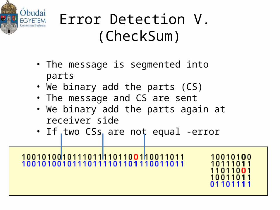
Error Detection V. (CheckSum)
• The message is segmented into parts• We binary add the parts (CS)• The message and CS are sent• We binary add the parts again at receiver side• If two CSs are not equal -error
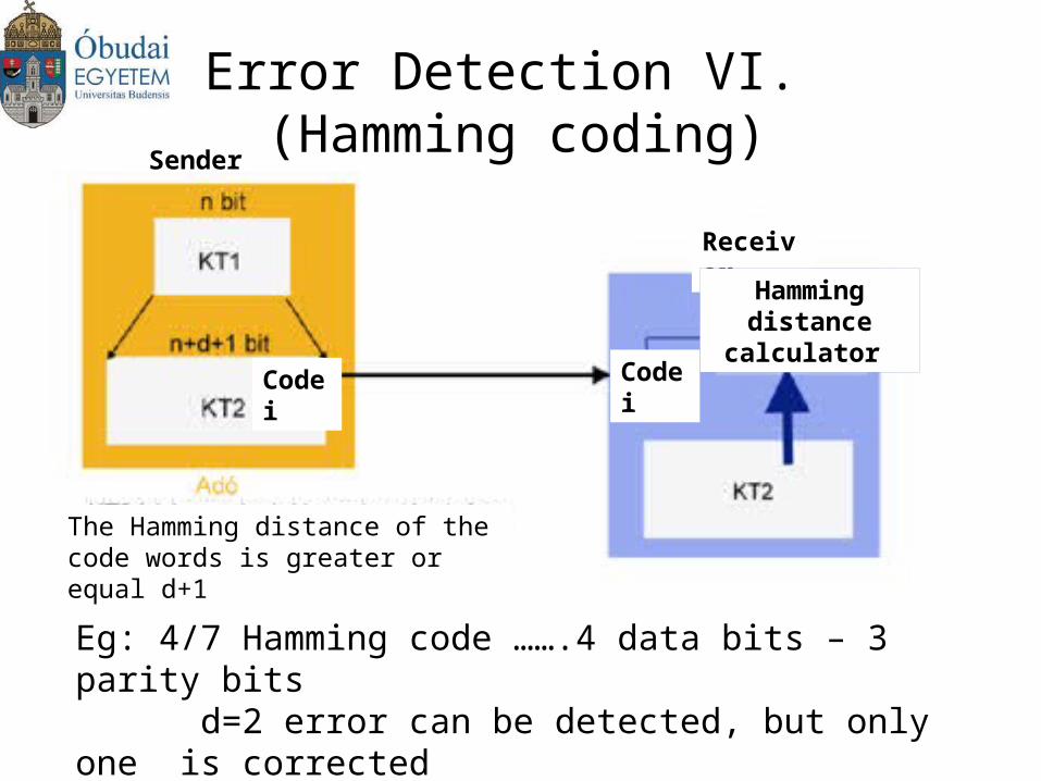
Error Detection VI. (Hamming coding)
Eg: 4/7 Hamming code …….4 data bits – 3 parity bits d=2 error can be detected, but only one is correctedNumber of parity bits = largest exponent (23)
Sender
Receiver
Code i Code i
Hamming distance
calculator
The Hamming distance of the code words is greater or equal d+1
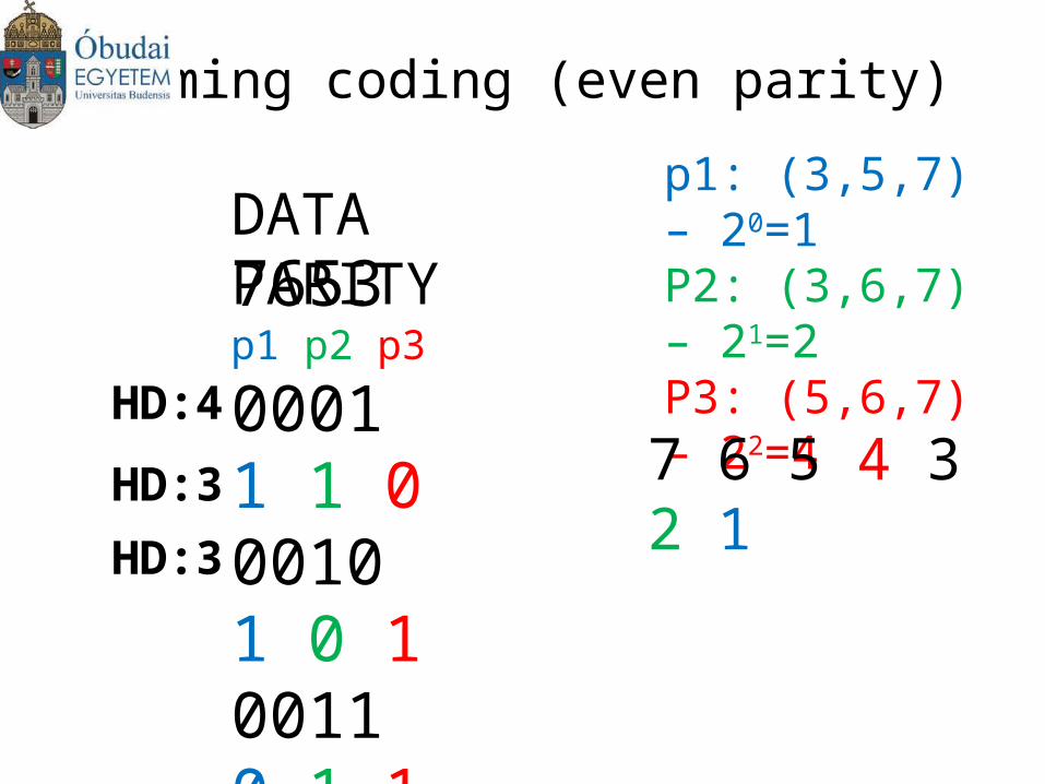
Hamming coding (even parity)
7653 p1 p2 p3
0001 1 1 00010 1 0 10011 0 1 10100 0 1 1
DATA PARITY
p1: (3,5,7) – 20=1P2: (3,6,7) – 21=2P3: (5,6,7) – 22=4
7 6 5 4 3 2 1HD:4
HD:3
HD:3
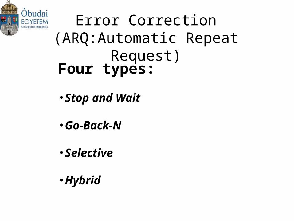
Error Correction(ARQ:Automatic Repeat Request)
Four types:
•Stop and Wait
•Go-Back-N
•Selective
•Hybrid
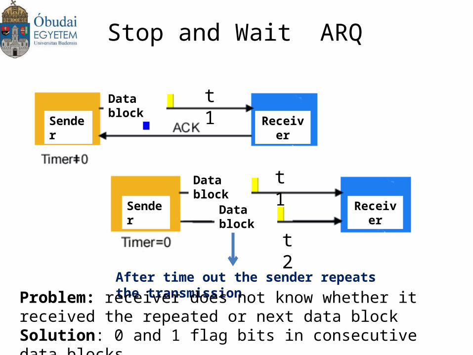
Stop and Wait ARQ
t1
t2
t1
After time out the sender repeats the transmission
Problem: receiver does not know whether it received the repeated or next data blockSolution: 0 and 1 flag bits in consecutive data blocks
Data block
Data block
Data block
Sender
Sender
Receiver
Receiver
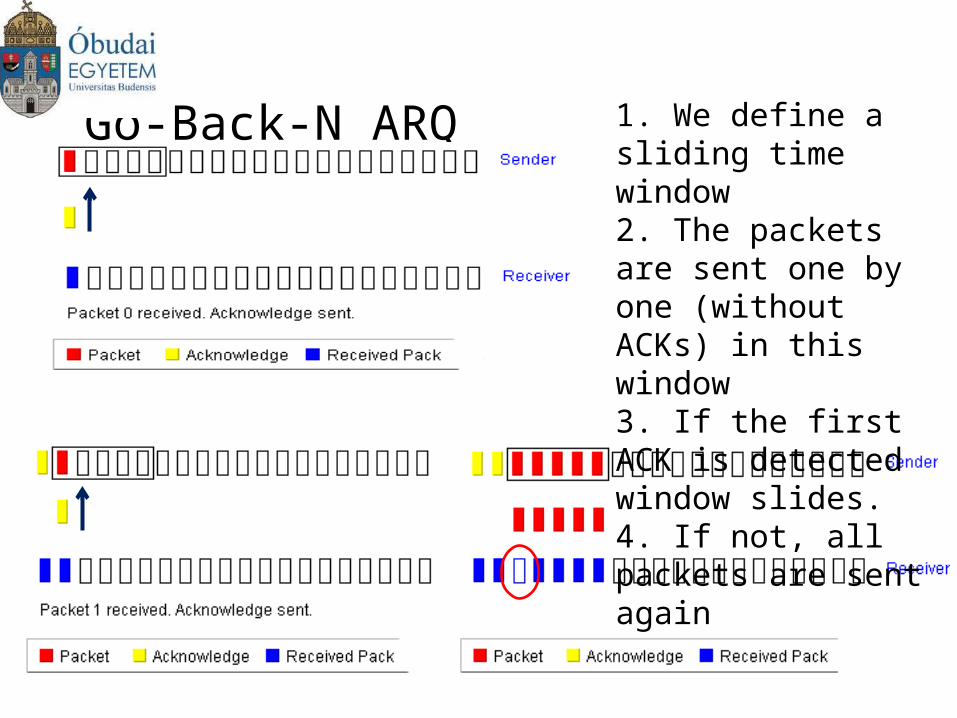
Go-Back-N ARQ1. We define a sliding time window2. The packets are sent one by one (without ACKs) in this window3. If the first ACK is detected window slides.4. If not, all packets are sent again
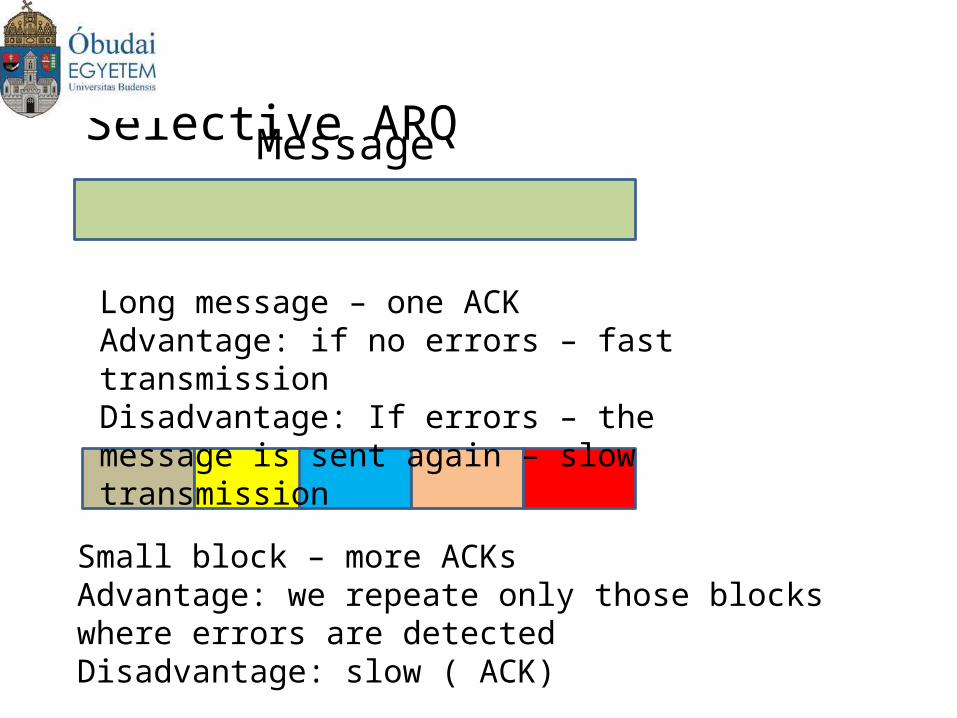
Selective ARQ
Message
Long message – one ACKAdvantage: if no errors – fast transmissionDisadvantage: If errors – the message is sent again – slow transmission
Small block – more ACKsAdvantage: we repeate only those blocks where errors are detected Disadvantage: slow ( ACK)
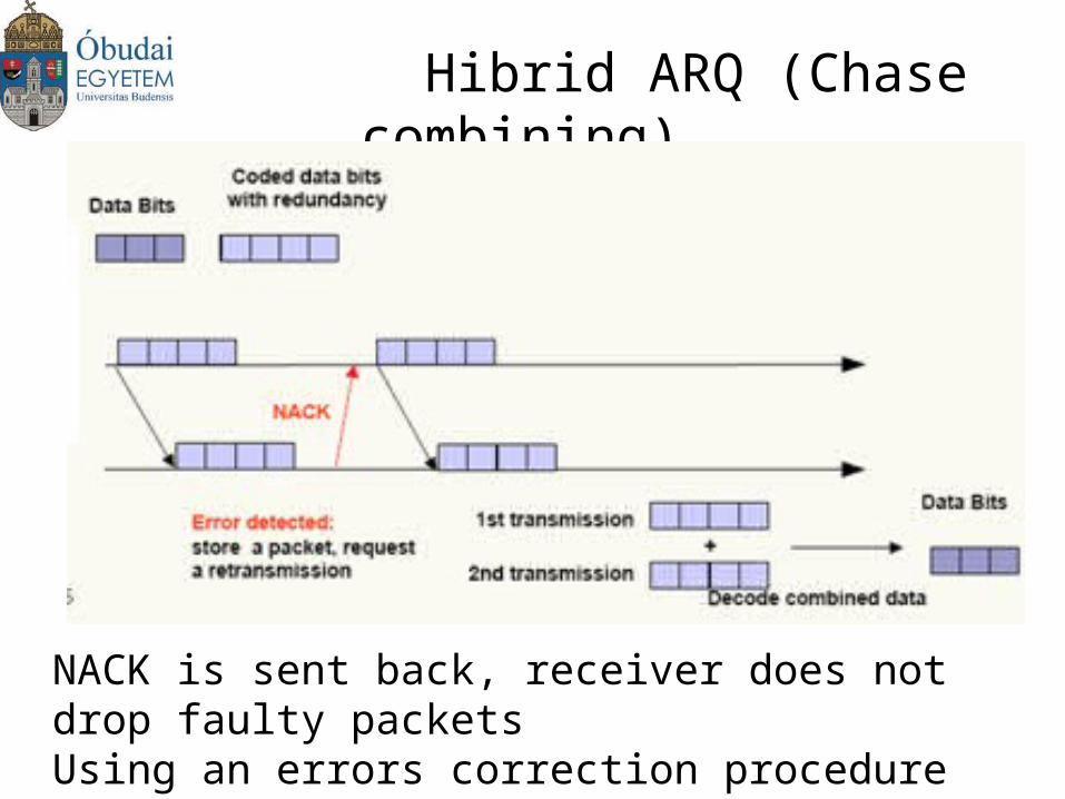
Hibrid ARQ (Chase combining)
NACK is sent back, receiver does not drop faulty packetsUsing an errors correction procedure we can repair the data from faulty packets
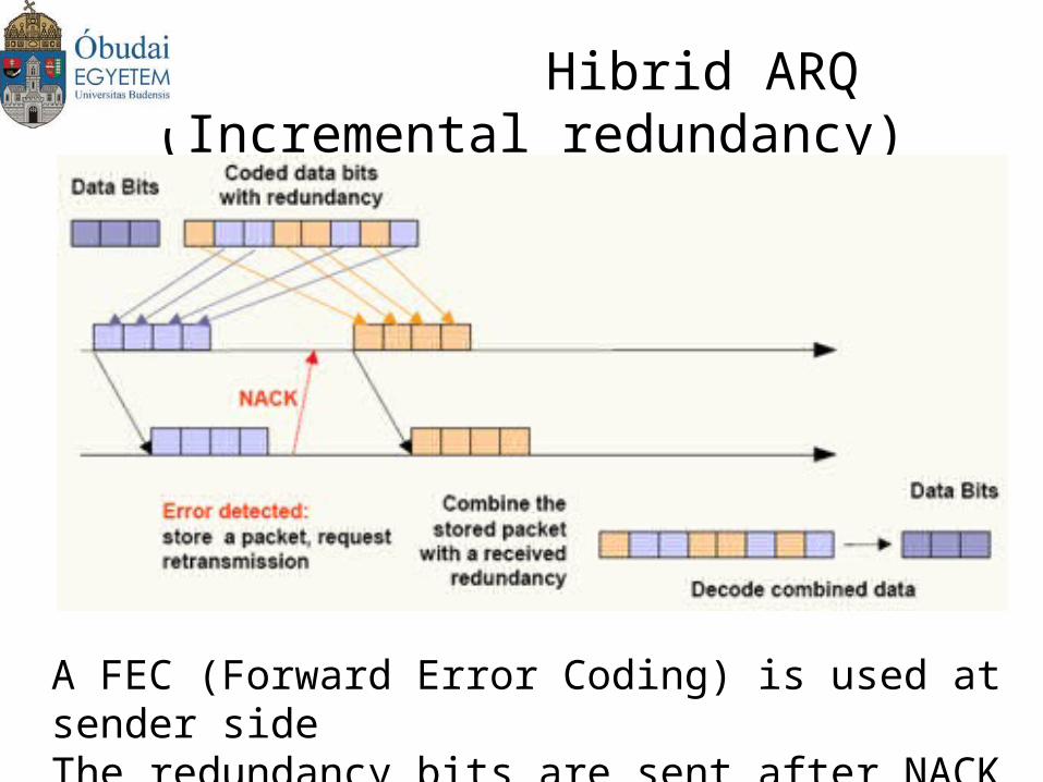
Hibrid ARQ (Incremental redundancy)
A FEC (Forward Error Coding) is used at sender sideThe redundancy bits are sent after NACK
Forward Error Coding: FEC
Two main types:
•Convolutional coding
•Block coding
We add redundancy bits which help correct data at the receiver
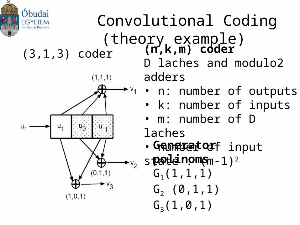
Convolutional Coding (theory example)
(n,k,m) coderD laches and modulo2 adders• n: number of outputs• k: number of inputs• m: number of D laches• number of input state : (m-1)2
(3,1,3) coder
Generator polinomsG1(1,1,1)G2 (0,1,1)G3(1,0,1)
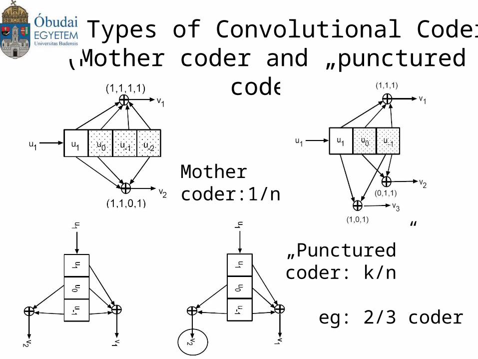
Types of Convolutional Coders (Mother coder and „punctured” coder)
Mother coder:1/n
„Punctured” coder: k/n
eg: 2/3 coder
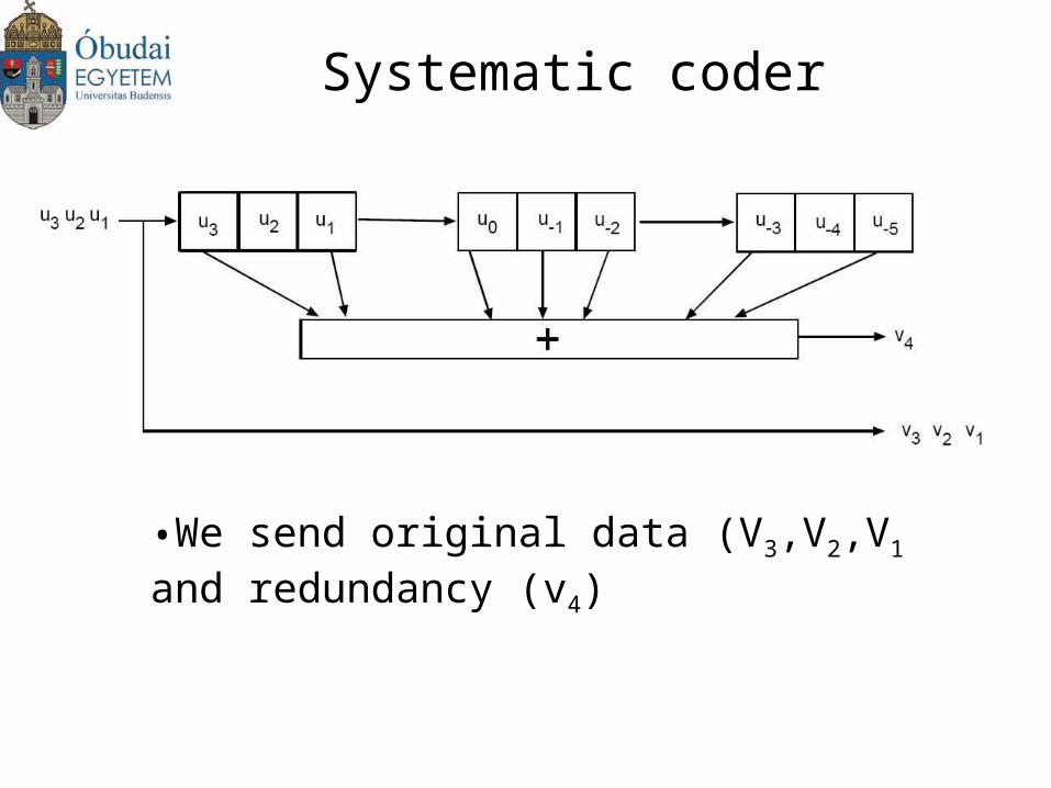
Systematic coder
•We send original data (V3,V2,V1 and redundancy (v4)
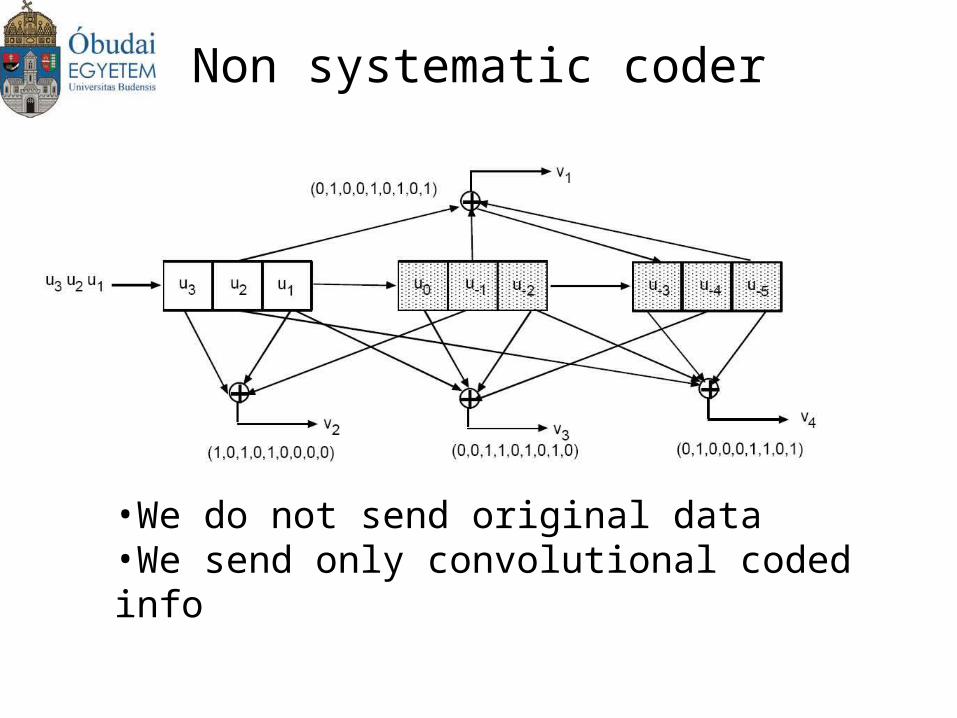
Non systematic coder
•We do not send original data•We send only convolutional coded info
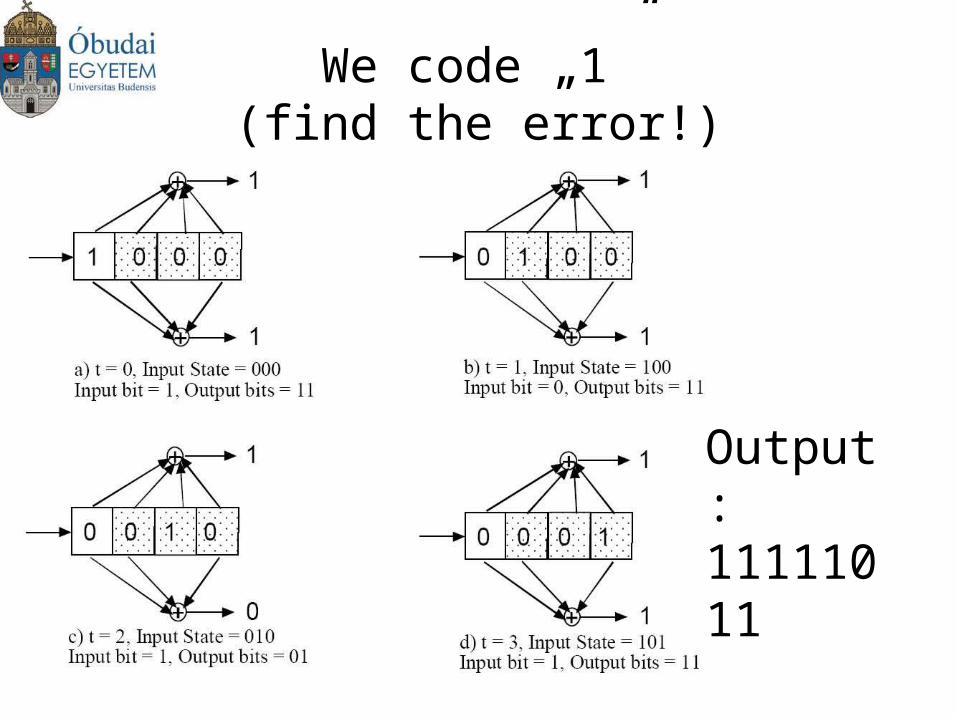
We code „1”(find the error!)
Output:11111011
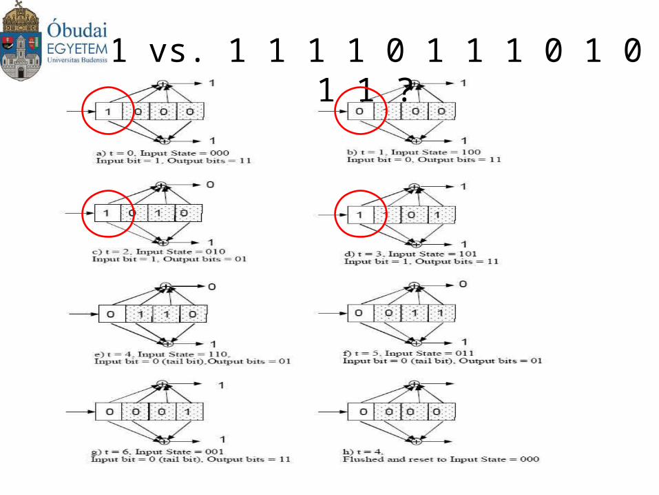
1011 vs. 1 1 1 1 0 1 1 1 0 1 0 1 1 1 ?
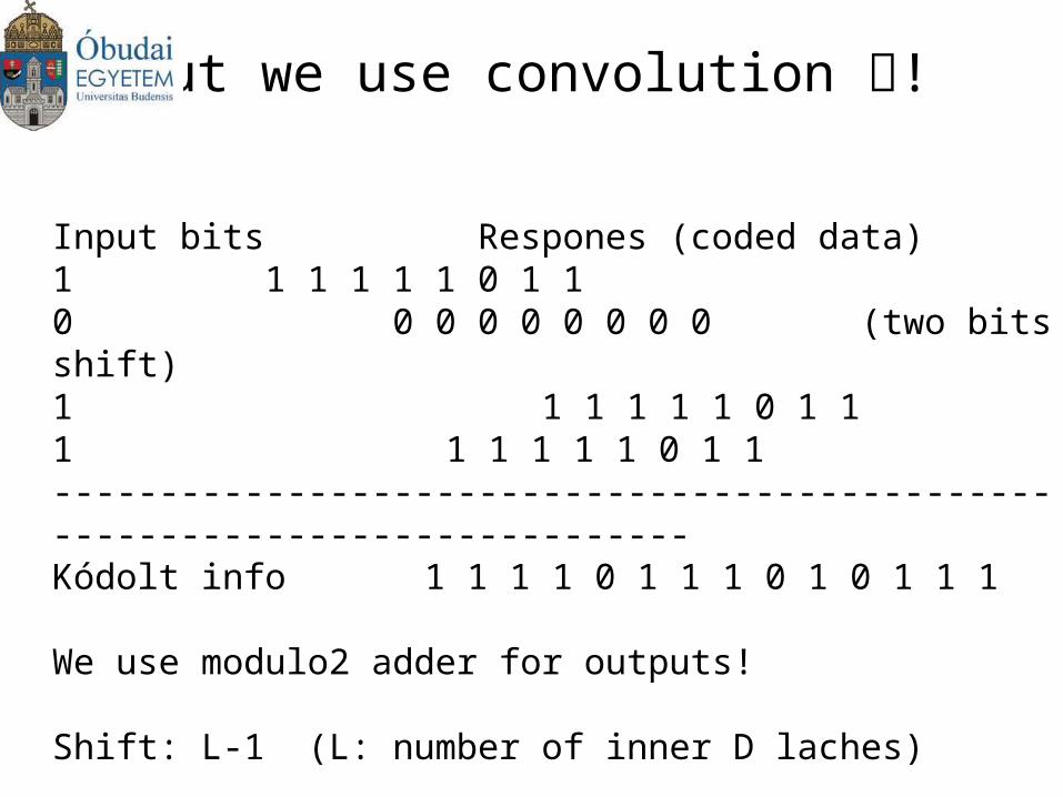
But we use convolution !
Input bits Respones (coded data)1 1 1 1 1 1 0 1 10 0 0 0 0 0 0 0 0 (two bits shift)1 1 1 1 1 1 0 1 11 1 1 1 1 1 0 1 1 -----------------------------------------------------------------------------Kódolt info 1 1 1 1 0 1 1 1 0 1 0 1 1 1
We use modulo2 adder for outputs!
Shift: L-1 (L: number of inner D laches)
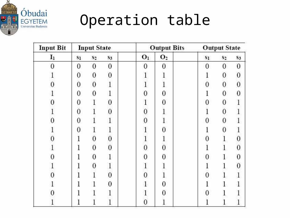
Operation table
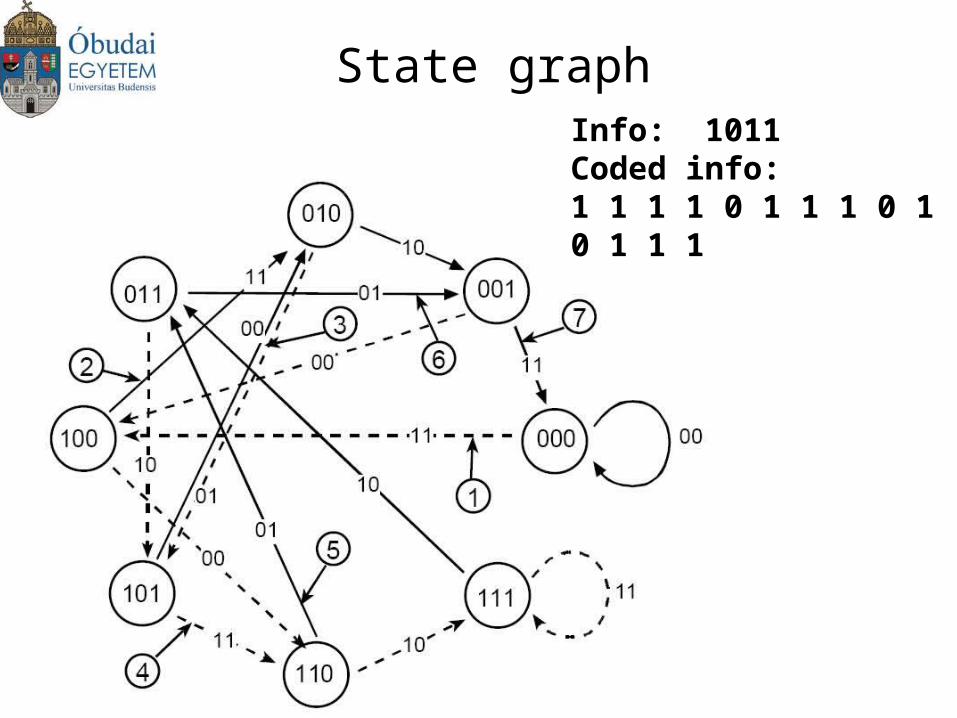
State graphInfo: 1011Coded info:1 1 1 1 0 1 1 1 0 1 0 1 1 1
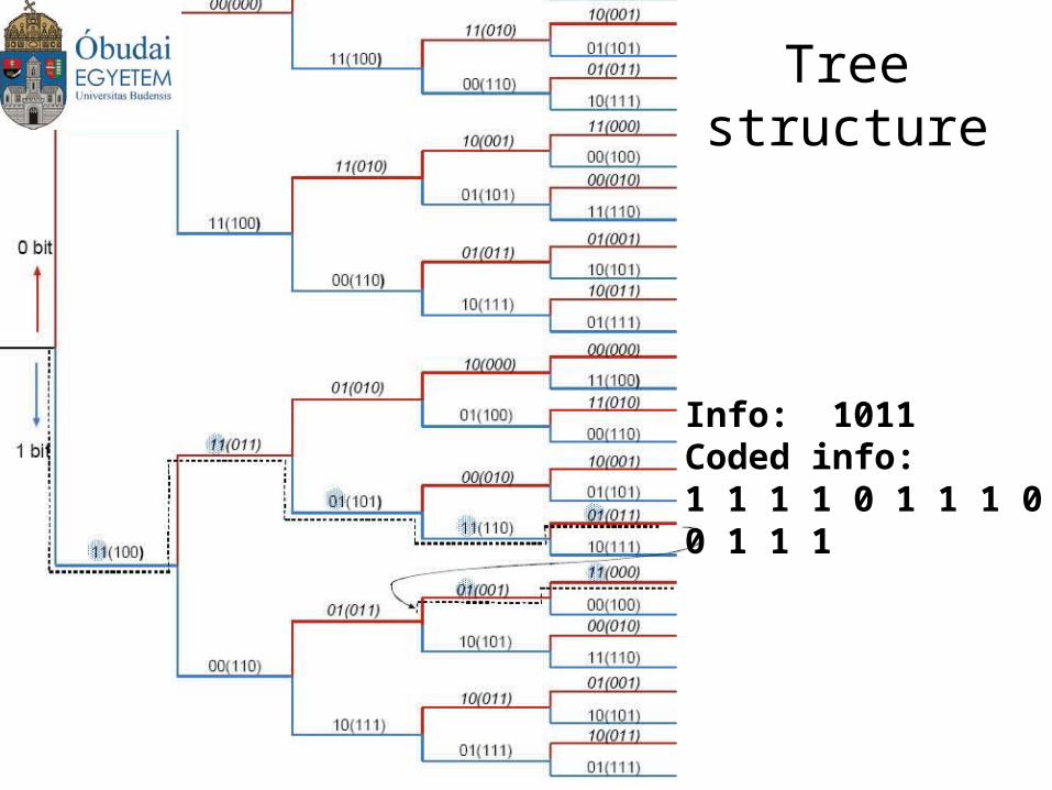
Tree structure
Info: 1011Coded info:1 1 1 1 0 1 1 1 0 1 0 1 1 1
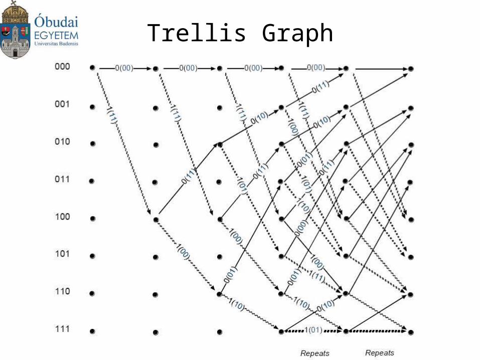
Trellis Graph
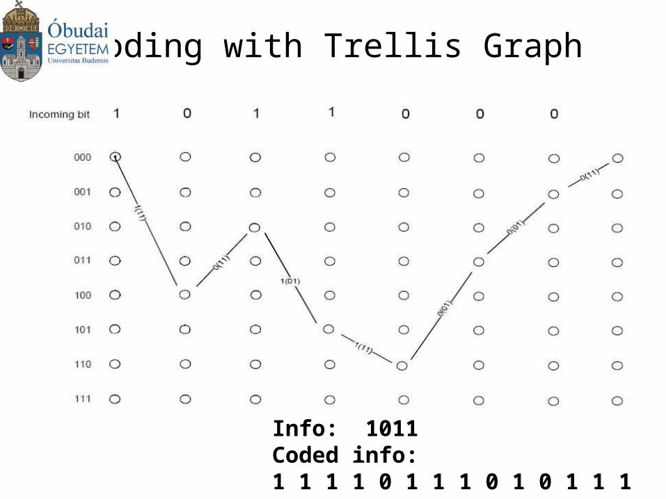
Coding with Trellis Graph
Info: 1011Coded info:1 1 1 1 0 1 1 1 0 1 0 1 1 1
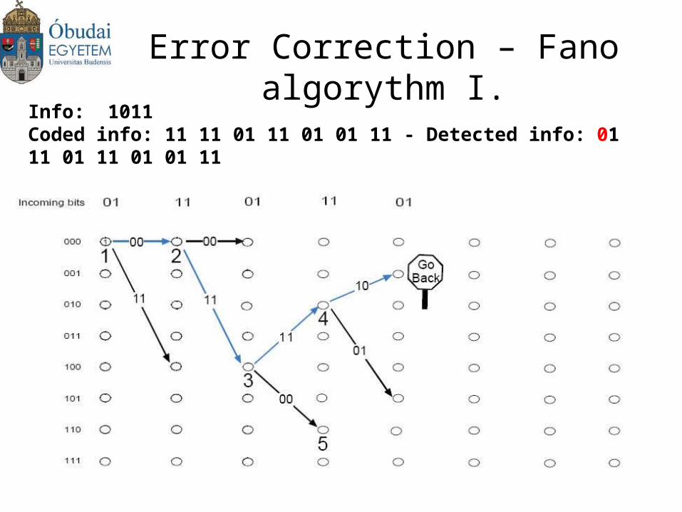
Error Correction – Fano algorythm I.
Info: 1011Coded info: 11 11 01 11 01 01 11 - Detected info: 01 11 01 11 01 01 11
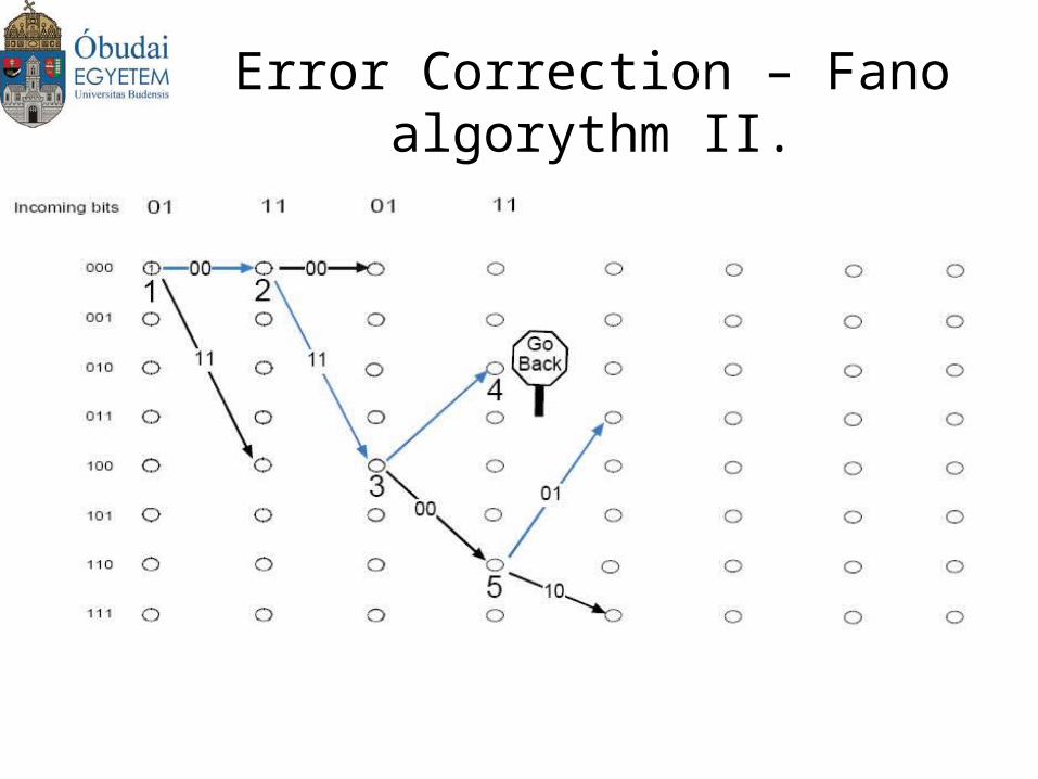
Error Correction – Fano algorythm II.

Error Correction – Fano algorythm III.
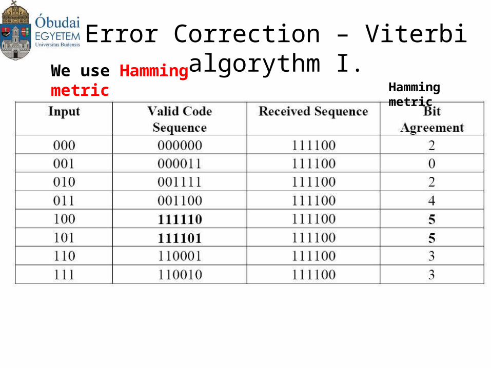
Error Correction – Viterbi algorythm I.
Hamming metricWe use Hamming metric
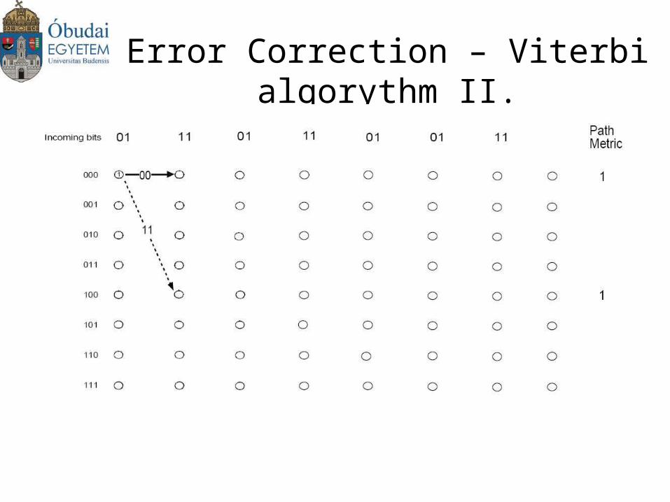
Error Correction – Viterbi algorythm II.
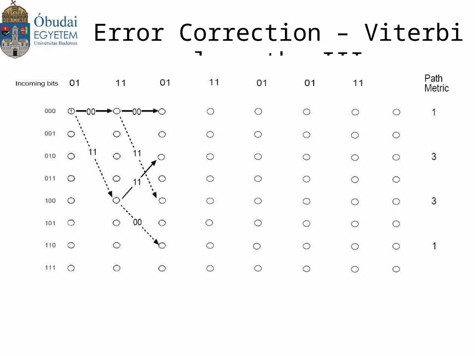
Error Correction – Viterbi algorythm III.
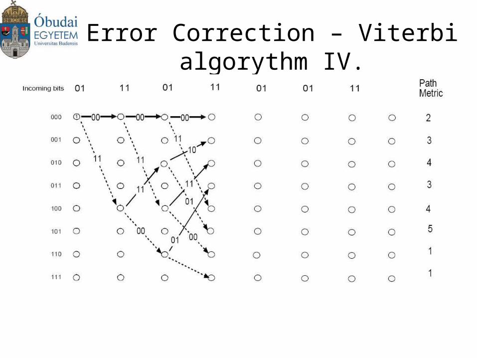
Error Correction – Viterbi algorythm IV.
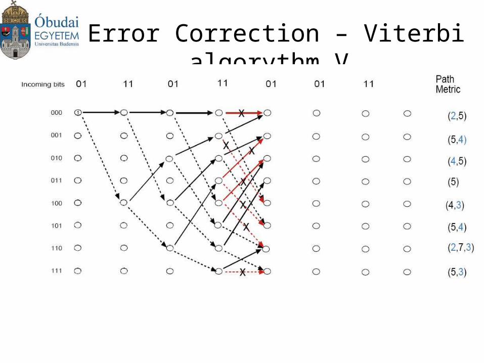
Error Correction – Viterbi algorythm V.
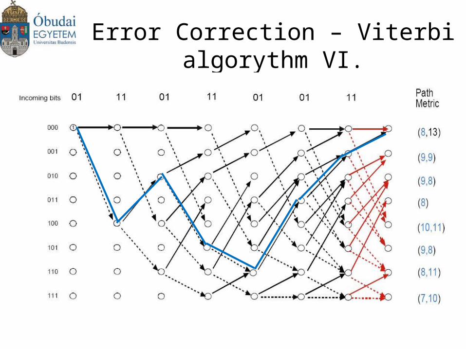
Error Correction – Viterbi algorythm VI.
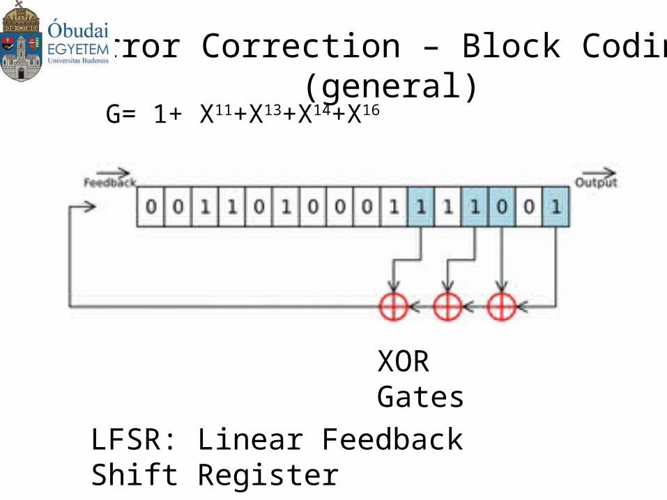
Error Correction – Block Coding (general)
G= 1+ X11+X13+X14+X16
XOR Gates
LFSR: Linear Feedback Shift Register
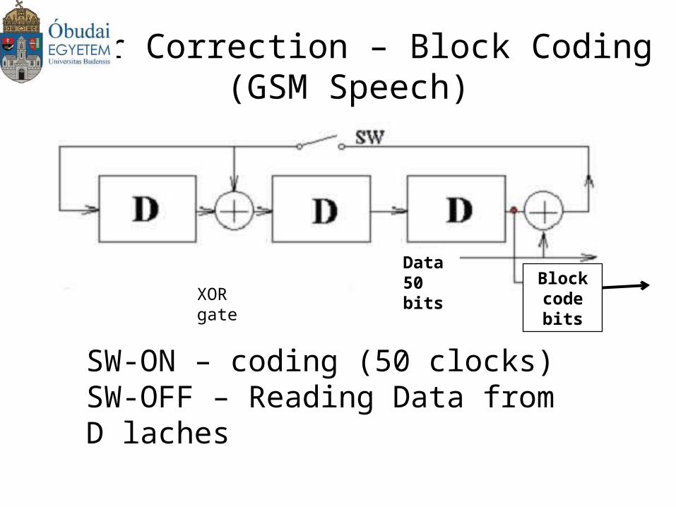
Error Correction – Block Coding (GSM Speech)
Data50 bits Block
code bitsXOR gate
SW-ON – coding (50 clocks)SW-OFF – Reading Data from D laches