dr. emad m. saad · 2015-11-24 · draught can be obtained by use of chimney, fan, steam or air jet...
TRANSCRIPT

1
Faculty of Engineering
Mechanical Engineering Dept.
Dr. Emad M. Saad Mechanical Engineering Dept.
Faculty of Engineering
Fayoum University
Schematic of a Thermal Power Plant
Lecture (6)
on
By
2015 - 2016
2
3
Lecture (6) –Thermal Power Stations – 4th year
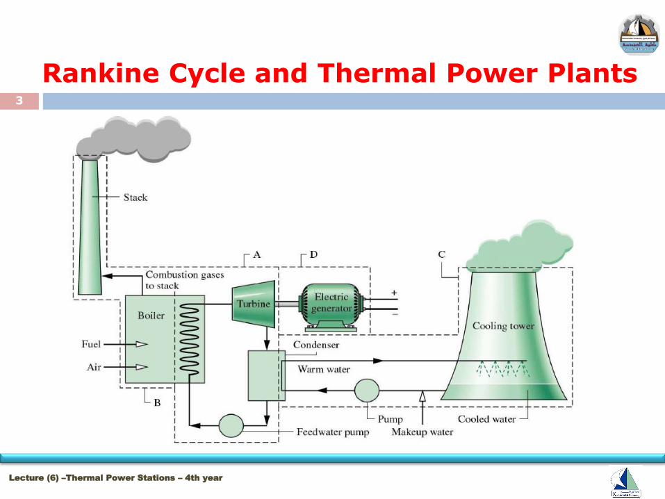
Rankine Cycle and Thermal Power Plants

4
Lecture (6) –Thermal Power Stations – 4th year
Rankine Cycle and Thermal Power Plants

5
Lecture (6) –Thermal Power Stations – 4th year
Rankine Cycle and Thermal Power Plants
6
Lecture (6) –Thermal Power Stations – 4th year
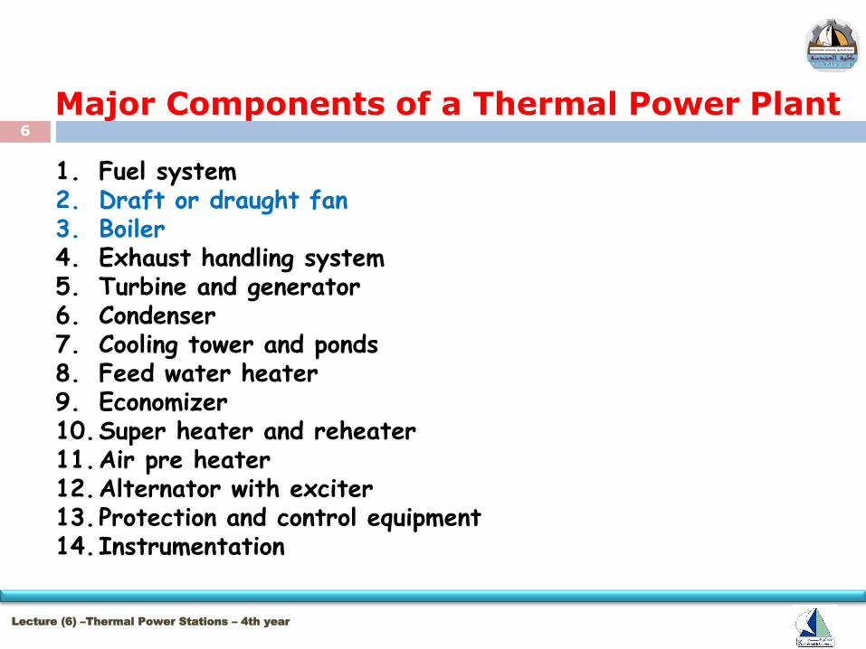
Major Components of a Thermal Power Plant
1. Fuel system 2. Draft or draught fan 3. Boiler 4. Exhaust handling system 5. Turbine and generator 6. Condenser 7. Cooling tower and ponds 8. Feed water heater 9. Economizer 10.Super heater and reheater 11.Air pre heater 12.Alternator with exciter 13.Protection and control equipment 14.Instrumentation

7
Lecture (5) –Thermal Power Stations – 4th year
Major Components of a Thermal Power Plant
1. Processes in coal handling plant (Ex. of fuel system)

8
Lecture (6) –Thermal Power Stations – 4th year
Major Components of a Thermal Power Plant
2. Draught System
9
Lecture (6) –Thermal Power Stations – 4th year
Major Components of a Thermal Power Plant
2. Draught System
The draught is one of the most essential systems of
thermal power plant which supplies required quantity of
air for combustion and removes the burnt products from
the system.
To move the air through the fuel bed and to produce a
flow of hot gases through the boiler, economizer,
preheater and chimney require a difference of pressure.

10
Lecture (6) –Thermal Power Stations – 4th year
Major Components of a Thermal Power Plant
2. Draught System This difference of pressure for to maintaining the constant flow of
air and discharging the gases through the chimney to atmosphere is
known as draught.
Draught can be obtained by use of chimney, fan, steam or air jet or
combination of these. When the draught is produced with the help of
chimney or stack only, it is known as Natural Draught and when the
draught is produced by any other means except chimney it is known as
artificial draught.
Natural draught has its limitation. Modern plants has high rate of
heat transfer and Draught losses are very high. in view of this
Natural draught is used only for small boilers.
11
Lecture (6) –Thermal Power Stations – 4th year
Major Components of a Thermal Power Plant
2. Draught System
A chimney is a structure for venting hot flue gases or smoke from a boiler, stove, furnace or fireplace to the outside atmosphere.
Chimneys are typically vertical, or as near as possible to vertical, to ensure that the gases flow smoothly,
Drawing air into the combustion in what is known as the stack/chimney, effect.
The space inside a chimney is called a flue.
Chimneys may be found in buildings, steam locomotives and ships.
A flue gas stack is a type of chimney, a vertical pipe, channel or similar structure through which combustion product gases called flue gases are exhausted to the outside air.
12
Lecture (6) –Thermal Power Stations – 4th year
Major Components of a Thermal Power Plant
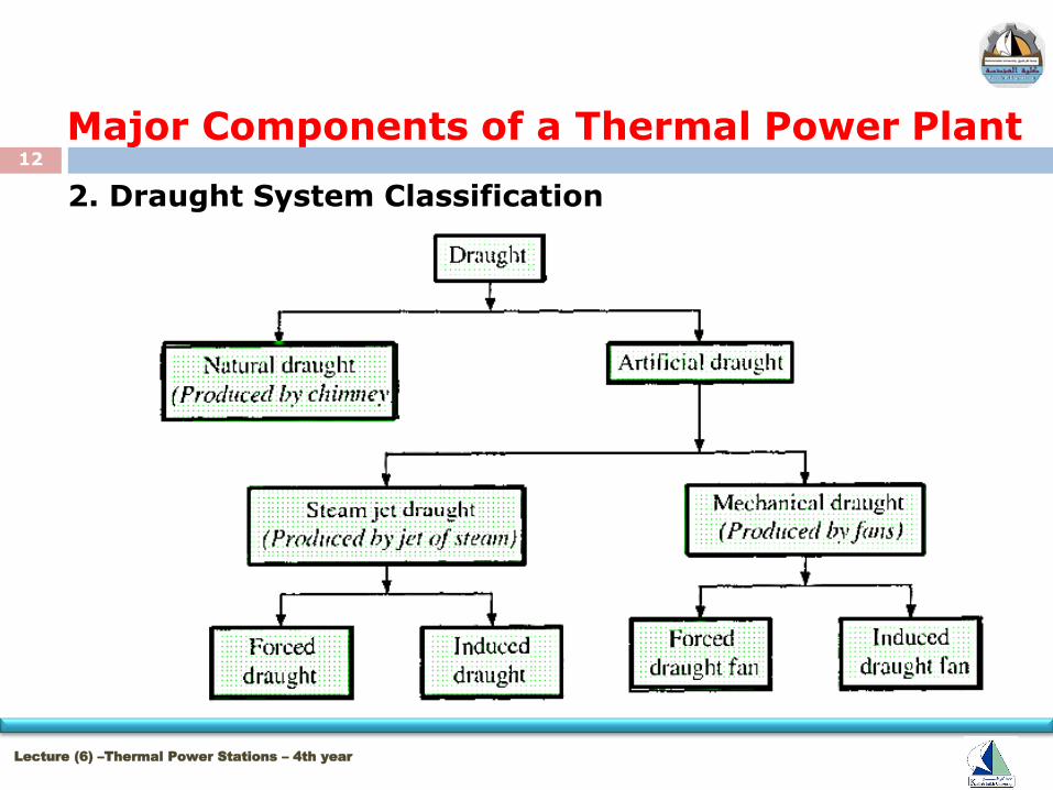
2. Draught System Classification
13
Lecture (6) –Thermal Power Stations – 4th year
Major Components of a Thermal Power Plant
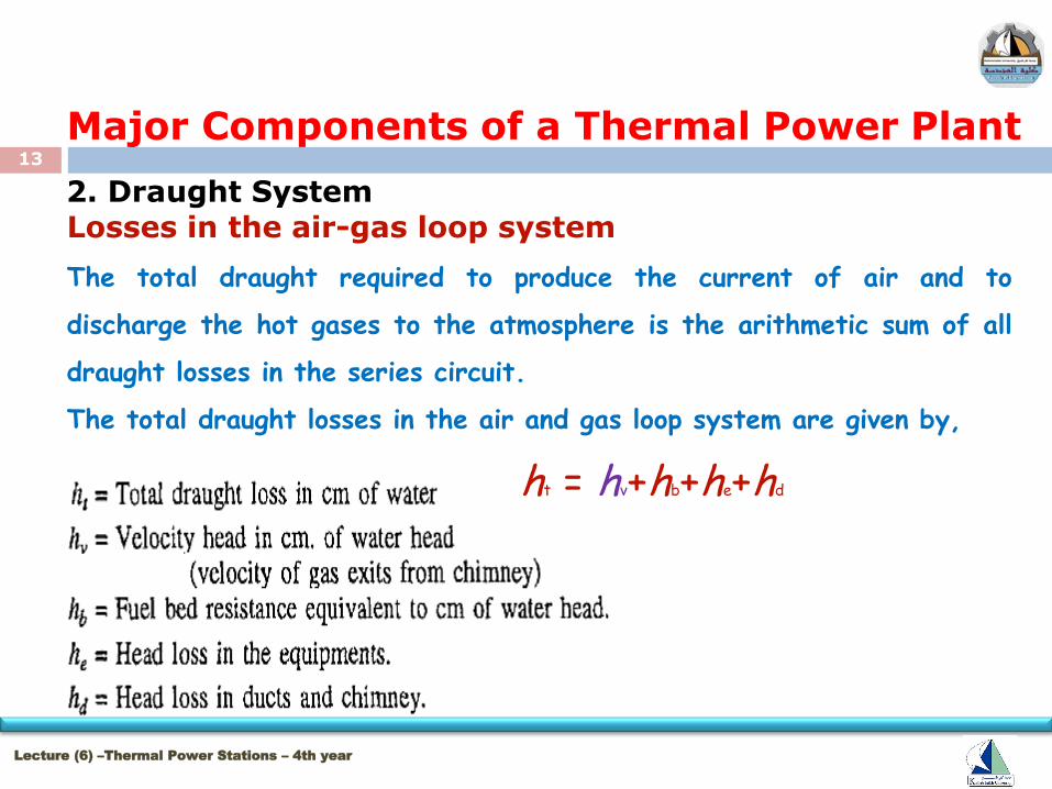
2. Draught System Losses in the air-gas loop system
The total draught required to produce the current of air and to
discharge the hot gases to the atmosphere is the arithmetic sum of all
draught losses in the series circuit.
The total draught losses in the air and gas loop system are given by,
ht = hv+hb+he+hd

14
Lecture (6) –Thermal Power Stations – 4th year
Major Components of a Thermal Power Plant
2. Draught System
15
Lecture (6) –Thermal Power Stations – 4th year
Major Components of a Thermal Power Plant
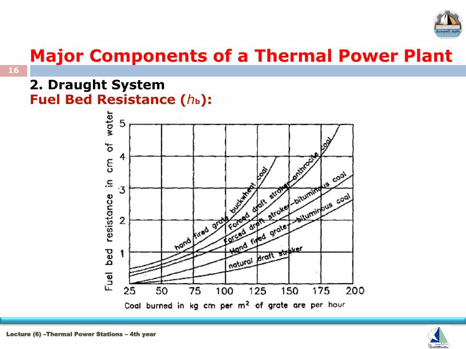
2. Draught System
Fuel Bed Resistance (hb):
The fuel bed resistance depends on fuel size, bed thickness and
combustion rate. The effect of combustion rate on resistance
for different types of stokers is shown in Fig. The resistance of
the spreader stoker is not shown in figure because much of the
coal is burned in suspension. The draught resistance of spreader
stoker may be taken as 6 cm of water head.
16
Lecture (6) –Thermal Power Stations – 4th year
Major Components of a Thermal Power Plant
2. Draught System Fuel Bed Resistance (hb):
17
Lecture (6) –Thermal Power Stations – 4th year
Major Components of a Thermal Power Plant
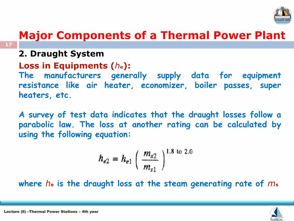
2. Draught System
Loss in Equipments (he): The manufacturers generally supply data for equipment resistance like air heater, economizer, boiler passes, super heaters, etc. A survey of test data indicates that the draught losses follow a parabolic law. The loss at another rating can be calculated by using the following equation: where he is the draught loss at the steam generating rate of ms
18
Lecture (6) –Thermal Power Stations – 4th year
Major Components of a Thermal Power Plant
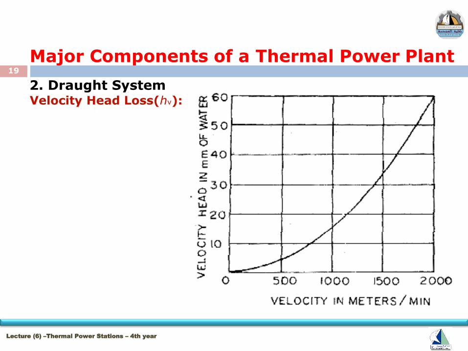
2. Draught System Velocity Head Loss(hv):
The draught system is designed to give minimum velocity head loss
U2/2g. (where u is the velocity at the exit of the chimney) But it must
be sufficient to diffuse and mix with the surrounding atmospheric air.
Its value also depends upon the natural air velocity at chimney height.
Higher velocity head is required if the natural air velocity is higher.
No general data can be given for such loss. It is decided as per the
site of the power plant, air temperature and natural air flow condition.
To know the velocity head, a velocity versus, velocity head in cm of
water is shown in Fig.
19
Lecture (6) –Thermal Power Stations – 4th year
Major Components of a Thermal Power Plant
2. Draught System Velocity Head Loss(hv):
20
Lecture (6) –Thermal Power Stations – 4th year
Major Components of a Thermal Power Plant
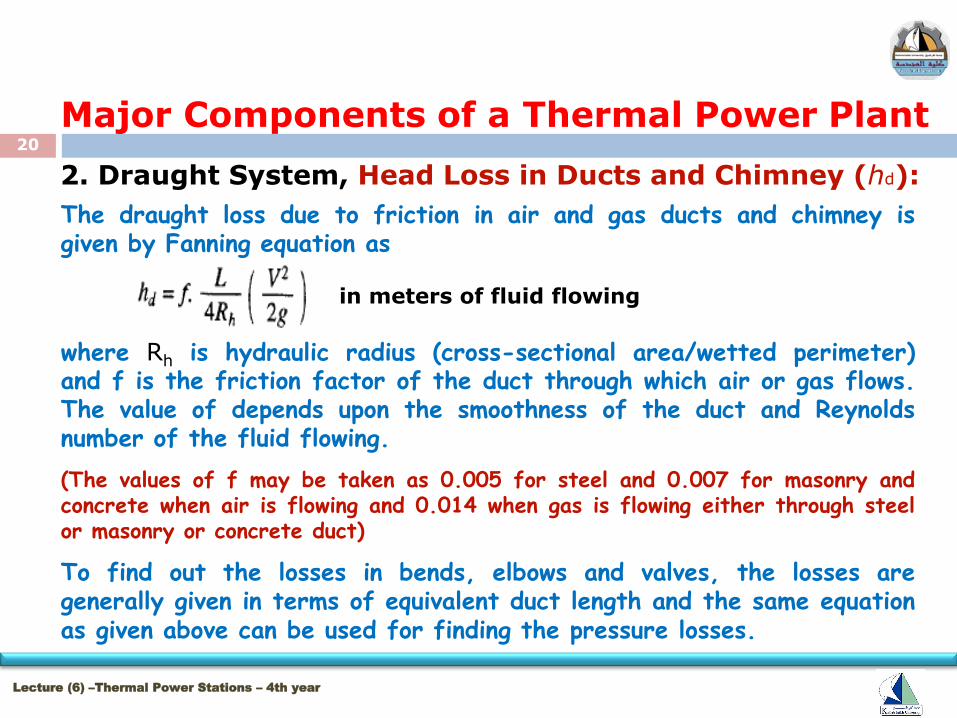
2. Draught System, Head Loss in Ducts and Chimney (hd): The draught loss due to friction in air and gas ducts and chimney is given by Fanning equation as
where Rh is hydraulic radius (cross-sectional area/wetted perimeter) and f is the friction factor of the duct through which air or gas flows. The value of depends upon the smoothness of the duct and Reynolds number of the fluid flowing.
(The values of f may be taken as 0.005 for steel and 0.007 for masonry and concrete when air is flowing and 0.014 when gas is flowing either through steel or masonry or concrete duct)
To find out the losses in bends, elbows and valves, the losses are generally given in terms of equivalent duct length and the same equation as given above can be used for finding the pressure losses.
in meters of fluid flowing
21
Lecture (6) –Thermal Power Stations – 4th year
Major Components of a Thermal Power Plant
2. Draught System
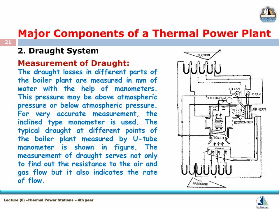
Measurement of Draught: The draught losses in different parts of the boiler plant are measured in mm of water with the help of manometers. This pressure may be above atmospheric pressure or below atmospheric pressure. For very accurate measurement, the inclined type manometer is used. The typical draught at different points of the boiler plant measured by U-tube manometer is shown in figure. The measurement of draught serves not only to find out the resistance to the air and gas flow but it also indicates the rate of flow.
22
Lecture (6) –Thermal Power Stations – 4th year
Major Components of a Thermal Power Plant
2. Draught System
Advantages and Limitations of Chimney / Natural Draught
Advantages 1. It does not require any external power for producing the
draught.
2. The capital investment is less. The maintenance cost is nil
as there is no mechanical part.
3. Chimney keeps the flue gases at a high place in the
atmosphere which prevents the contamination of
atmosphere.
4. It has long life.
23
Lecture (6) –Thermal Power Stations – 4th year
Major Components of a Thermal Power Plant
2. Draught System Advantages and Limitations of Chimney / Natural Draught
Limitations
1. The maximum pressure available for producing natural draught
by chimney is hardly 10 to 20 mm of water under the normal
atmospheric and flue gas temperatures.
2. The available draught decreases with increase in outside air
temperature and for producing sufficient draught, the flue
gases have to be discharged at comparatively high
temperatures resulting in the loss of overall plant efficiency.
And thus maximum utilization of Heat is not possible.

24
Lecture (6) –Thermal Power Stations – 4th year
Major Components of a Thermal Power Plant
2. Draught System Advantages and Limitations of Chimney / Natural Draught
Limitations
3. As there is no through mixing of air and fuel in the combustion chamber due to low velocity of air therefore combustion is very poor. This increases the specific fuel consumption.
4. The chimney has no flexibility to create more draught under peak load conditions because the draught available is constant for a particular height of chimney and the draught can be increased by allowing the flue gases to leave the combustion chamber at higher temperatures. This reduces the overall efficiency of the plant.
25
Lecture (6) –Thermal Power Stations – 4th year
Major Components of a Thermal Power Plant
2. Draught System Advantages and Limitations of Chimney / Natural Draught
Nearly 20% heat released by the fuel is lost to the flue gases.
The chimney draught is only used for very small boilers.
Nowadays the chimney is never used for creating draught in
thermal power plants as it has no flexibility, the total draught
produced is insufficient for high generating capacity. The chimney
is used in all power plants only to discharge the flue gases high in
the atmosphere to maintain the cleanliness of the surrounding
atmospheric air.

26