dr richard waller, keele university, [email protected] c-change in gees: changing...
TRANSCRIPT

Dr Richard Waller, Keele University, [email protected] in GEES: Changing Permafrost Environments – Geotechnical Problems
The Principal Problems
1. Frost heave associated with freeze-back of the active layer during the winter.
2. Thaw subsidence - thaw of ice-rich permafrost and associated terrain disturbance.
3. Hydrological and groundwater characteristics - problems of water supply and waste disposal in particular.Retrogressive thaw slump on
Summer Island, Mackenzie Delta
R.I. Waller

Dr Richard Waller, Keele University, [email protected] in GEES: Changing Permafrost Environments – Geotechnical Problems
Thermal Disturbance
Major construction problem, which relates to the thermal sensitivity of permafrost.
Modification of the ground thermal regime can lead to two problems:
1) Thaw subsidence: ground warming; increase in depth of active layer.
2) Frost heave: can occur seasonally (within active layer) or more permanently (permafrost aggradation).
N.B. Only a problem where material is frost susceptible and resulting frozen ground is ice-rich.
R.I. Waller

Dr Richard Waller, Keele University, [email protected] in GEES: Changing Permafrost Environments – Geotechnical Problems
Human activities cause problems by changing the surface boundary
conditions and modifying the surface
energy balance.
PERMAFROSTTHICKNESS
CLIMATE
GROUNDSURFACE
TEMP.
GROUNDTHERMALREGIME
Surface energybalance
Groundthermal
properties(+time)
Surface boundary conditions

Dr Richard Waller, Keele University, [email protected] in GEES: Changing Permafrost Environments – Geotechnical Problems
Thaw Subsidence
• Disturbance of surface boundary conditions usually results in an increase in surface temperatures and thermokarst development.
• Common causes:– Disturbance or clearance of vegetation Associated loss
of surface insulation.– Construction of heated building.– Stripping of surface materials: e.g. to supply construction
materials.– Movement of vehicles: seismic lines from 1950s still
visible in ice-rich tundra regions.
Dr Richard Waller, Keele University, [email protected] in GEES: Changing Permafrost Environments – Geotechnical Problems
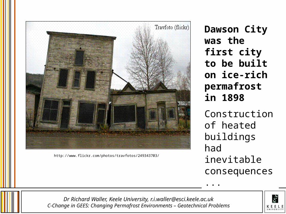
Dawson City was the first city to be built on ice-rich permafrost in 1898
Construction of heated buildings had inevitable consequences...
http://www.flickr.com/photos/travfotos/249343703/

Dr Richard Waller, Keele University, [email protected] in GEES: Changing Permafrost Environments – Geotechnical Problems
Stripping of Surface MaterialsCase Study: Banks Island
• Relates to construction of an airstrip between 1959-62.
• Thawed surface gravels were stripped and moved by bulldozer to provide a level runway.
• Subsequent thaw of underlying ice-rich sands with 20-35% volumetric excess ice content (and ice wedges).
• Development of hummocky thermokarst terrain and widespread landscape disturbance.
French, H.M. (1975) Man-induced thermokarst, Sachs Harbour Airstrip, Banks Island, Northwest Territories. Canadian Journal of Earth Sciences, 12, 132-144.
http://www.nasa.gov/centers/ames/images/content/173629main_dryvalleys-4-hires.jpg
Thaw lakes on Banks Island
Dr Richard Waller, Keele University, [email protected] in GEES: Changing Permafrost Environments – Geotechnical Problems
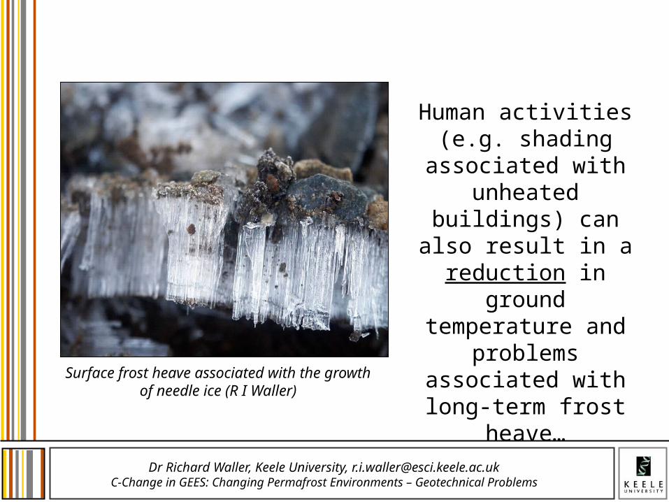
Human activities (e.g. shading associated with unheated buildings) can
also result in a reduction in ground
temperature and problems associated with long-term frost
heave…
Surface frost heave associated with the growth of needle ice (R I Waller)

Dr Richard Waller, Keele University, [email protected] in GEES: Changing Permafrost Environments – Geotechnical Problems
Controlling Factors
• Three factors determine the potential severity of permafrost degradation:
– Ice content of the permafrost (notably presence/absence of excess ice).
– Thickness and insulating qualities of the surface vegetation.
– Duration and warmth of the summer thaw period.
Must be considered when assessing the risk and planning remedial measures.
R.I. Waller

Dr Richard Waller, Keele University, [email protected] in GEES: Changing Permafrost Environments – Geotechnical Problems
Gravel Pads
• Most common solution is to build structure on a pad of coarse-grained sediment.
• Physically separates structure from the permafrost.
• Coarse-grained material is non-frost susceptible - limits frost heave.
• Commonly used in construction of roads, airstrips, buildings etc.
• Needs careful design – aim to provide insulation equivalent to pre-existing surface materials.
Heated fuel oil tank resting on a ventilated, gravel pad. Inuvik,
Canadian N.W.T.
R.I. Waller

Dr Richard Waller, Keele University, [email protected] in GEES: Changing Permafrost Environments – Geotechnical Problems
If too thin (a):level of insulation will be reduced, seasonal temperature fluctuations will increase, and active layer will deepen, causing subsidence.
If too thick (b):level of insulation is increased, fluctuations will decrease and active layer will thin, leading to frost heave.
Gravel Pad Design
Figure from: French, H.M. 2007. The Periglacial Environment (3rd ed.). Wiley & Sons, Chichester.© Wiley and Sons

Dr Richard Waller, Keele University, [email protected] in GEES: Changing Permafrost Environments – Geotechnical Problems
Additional Solutions
• Piles: If structure is likely to generate large amounts of heat, whole structure is usually mounted on piles driven into the permafrost. – Allows circulation of
air and greater physical separation.
• Thermosyphons: Passive heat pumps can be used to enhance the degree of cooling. Used in important structures such as dams.
Houses in Nuiqsut (Alaska) built on wooden piles
R.I. Waller

Dr Richard Waller, Keele University, [email protected] in GEES: Changing Permafrost Environments – Geotechnical Problems
Thermosyphons
Passive heat pumps used to enhance cooling of foundations.Sealed pipe containing a volatile fluid that transfers heat in response to a thermal gradient (e.g. Ammonia, pressurised CO2).Two parts:
Evaporator (buried in ground).Condensor (above ground).When evaporator (ground) is warmer than the condensor (air): Fluid evaporates (removes heat).Rises into the condensor and condenses (releases heat).Sinks back into the evaporator.
Thermosyphons providing additional cooling around a fuel oil tank
R.I. Waller
Dr Richard Waller, Keele University, [email protected] in GEES: Changing Permafrost Environments – Geotechnical Problems
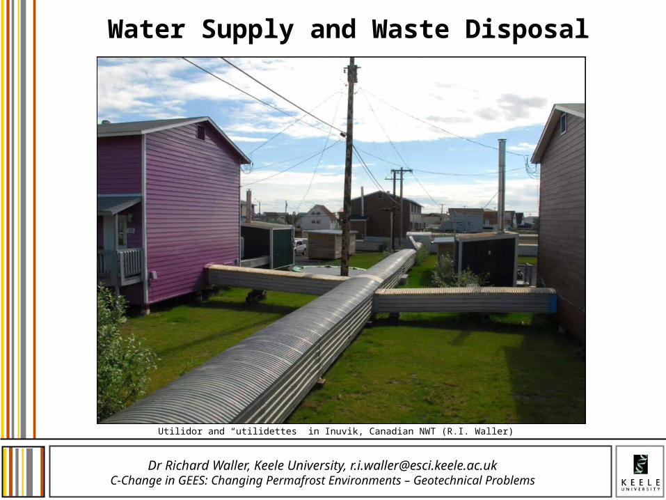
Water Supply and Waste Disposal
Utilidor and “utilidettes” in Inuvik, Canadian NWT (R.I. Waller)

14
Contents
•Introduction•Site investigation •Site considerations •Considerations for the foundations•Earth structures •Buried structures •Monitoring of geotechnical parameters

15
Siting process• Regional analysis
High level review of an area where there is an interest to build a nuclear power plant to identify some potential sites. This is largely based on excluding areas that do not meet some high level criteria such as adequate water supplies or seismic stability.
Potential sites (sites within the area of interest not ruled out by the regional analysis)
This analysis shall be conducted as much as possible on the basis of existing data without engaging important survey means (mainly for confidentiality reasons).
• Screening analysis / Site selectionReduce the number of potential sites to a few (less than 10) candidate sites that can then be analyzed in detail. This involves either further exclusion criteria or very simple assessment to identify those sites that are most likely to provide a suitable site. The sites from this step are called candidate sites.
Candidate sites (a list of less than 10 sites that appear suitable and can be ranked ).
• Ranking analysis /Site selection final step of the process Preferred candidate sites (sites suitable and choose to implement
a nuclear power programme).
16
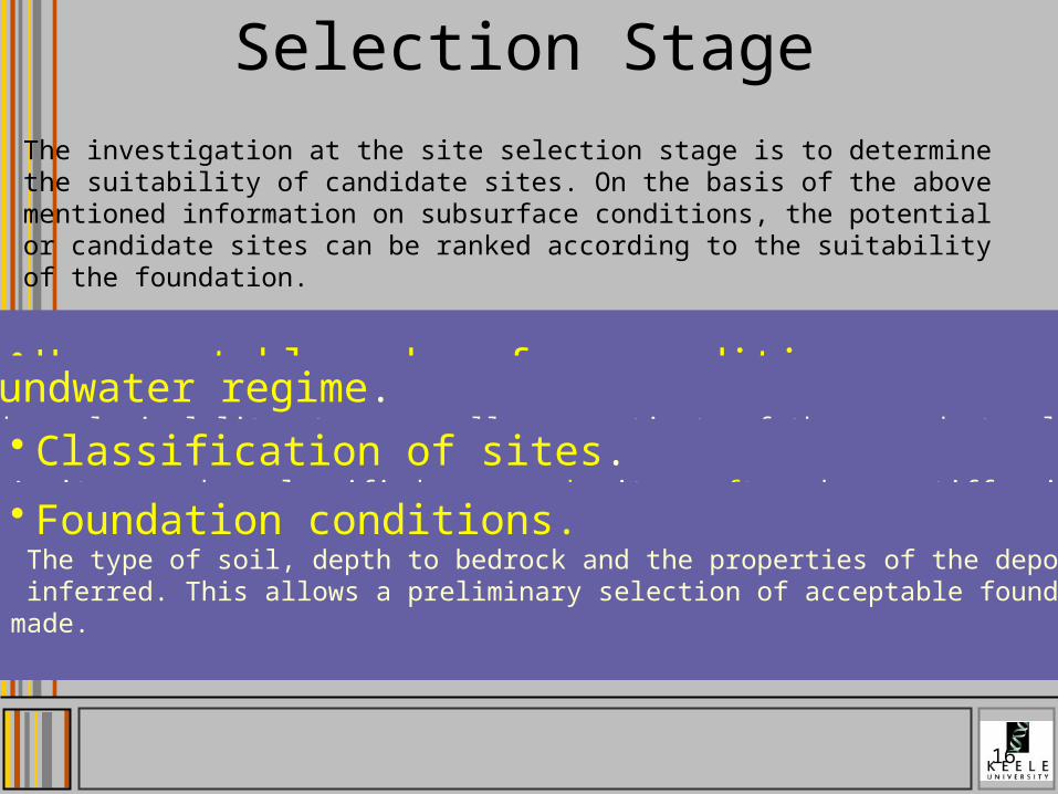
Selection StageThe investigation at the site selection stage is to determine the suitability of candidate sites. On the basis of the above mentioned information on subsurface conditions, the potential or candidate sites can be ranked according to the suitability of the foundation.
• Unacceptable subsurface conditions. – A site with geological conditions that could affect the safety of a nuclear
power plant and that cannot be corrected by means of a geotechnical treatment or compensated for by constructive measures is unacceptable.Geological hazards such as surface faulting, volcanic activity, landslides, permafrost, erosion processes, subsidence and collapse due to underground cavities
• Groundwater regime. The hydrogeological literature may allow an estimate of the groundwater location and regime (see IAEA Safety Series No.50-SG-S6).• Classification of sites.
A site may be classified as a rock site, soft rock or stiff soil site, soft soil site, or a combination thereof . The soil type is further divided into a non-cohesive andcohesive soil.• Foundation conditions. The type of soil, depth to bedrock and the properties of the deposit may be inferred. This allows a preliminary selection of acceptable foundation types to be made.

17
Verification Stage
• Geological hazards, geological and subsurface conditions• Liquefaction potential• Feasible foundation types (preliminary bearing capacity and foundation stability, preliminary settlement ranges• Groundwater levels and regime• Site preparation requirements (earthworks, excavations…)• Site investigation techniques used at this stage
– Seismic refraction and reflection survey – Rotary borehole drilling – In situ mechanical testing – Laboratory testing
In this stage, the investigation programme should cover the site as a whole as well as a smaller scale appropriate for layout considerations

Confirmation stage• In this stage, preliminary plant characteristics such as the
loads, the physical dimensions of the buildings, preliminary structural engineering criteria and the preferred plant layout are know
• In this stage, sufficient in situ and laboratory testing should be conducted to allow the estimation of the bearing capacity, determination of settlements of structure and the site amplification of seismic waves, establishment of soil– structure interaction parameters (dynamic and static), evaluation of the liquefaction potential and evaluation of a site specific design response spectrum, if required.
• As a minimum, the following indicators of potential cavities and susceptibility to ground collapse should be considered:– Sinks, sink ponds, caves and caverns, sinking streams, historical
ground subsidence, mines, surface depressions, Rock types such as limestone, dolomite, gypsum, anhydrite, halite,
18

19
Before operation of NPP
• Pre-operational stage :complete and refine the assessment of site characteristics by incorporating geotechnical data newly obtained during foundation excavation and construction.
• Operational Stage :• settlement of structures should be measured and used to confirm its safety and
integrity by comparing with prediction analyses ,• level of the water table, should be measured and compared with predictions to enable
an updated safety assessment to be made


21
Sources of Data• Historical and current documents– maps (topographic, geological, geophysical,soil…)– geotechnical reports and other geotechnical literature– earth satellite imagery – aerial photographs water well reports and water supply reports– oil and gas well records– hydrogeologic maps, hydrologic and tidal data, flood, climate and rainfall records– mining history, old mine plans and subsidence records– seismic data and historical earthquake records– newspaper accounts of events of significance– records of performance of structures in the vicinity. • In situ investigation tests• Laboratory tests

22
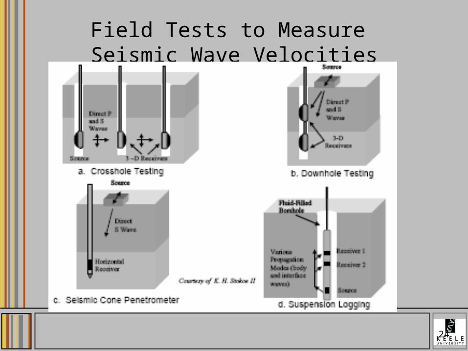
Geophysical in situ tests Nature of materials Parameters
measured Types of problems Commentaries
Cross hole seismic test Gravel to cohesive Shear wave velocity
Site categorization, SSI
Uphole/downhole seismic test
Gravel to cohesive Shear wave velocity
Site categorization, SSI
1 hole instead of 2 holes
Electrical resisitivity Gravel to cohesive Porosity and water content
Internal erosion Using of logging
Nuclear logging
Gravel to cohesive Water content
Surface seismic investigation
All types Surface wave velocity
Site categorization
Microgravimetry All types Acceleration due to gravity
Sinkholes, heterogeneities
Subsurface complex
Ground Penetrating Radar
All types Speed of propagation
Cavities Subsurface complex
Acoustic All types Speed of propagation
Damaged zones Dikes and dams maintenance
Magnetic technics All types Magnetic field intensity
Areas of humidity Dikes and dams maintenance

What is geophysics ?• Seismology - Study of natural
[from earthquakes] and man-induced seismic waves
• Gravity - Study of variations in earth's gravitational field
• Electrical Methods - Use of electrical conductivity / resistance of earth
• Electromagnetics - Study of induced electromagnetic fields
• Magnetics - Analysis of variations in earth's magnetic field
• Radioactivity - Study of natural and induced response to radioactivity
23

25
Geotechnical in situ tests Nature of
materials Parameters measured
Type of problem Commentaries
Flat jack test Rock In situ normal stress Convergence Hydraulic fracturing test Rock In situ stress state Convergence Direct shear stress test Rock Shear strength Stability problems Plate bearing tests Clay, sand, gravel Reaction modulus Compaction control
Settlement Used for excavations and embankments
Pressure meter test
Clay, sand, gravel Elasticity modulus Compressibility
Settlement Bearing capacity
Needs a preliminary hole
Static penetrometer test
Clay, sand, gravel Cone resistance
Bearing capacity Shear strength
Called also cone penetrometer test
Dynamic penetrometer test
Clay, sand, gravel Cone resistance Relative density
Liquefaction Called also Standard Penetration Test
Vane shear test Cohesive soil Shear strength Bearing capacity, slope stability
Pumping test Clay, sand, gravel Field permeability Transmissivity of soil
Needs piezometers
Overcoring tests Cohesive soils and rocks
In situ stress state Consolidation studies
Needs laboratory tests
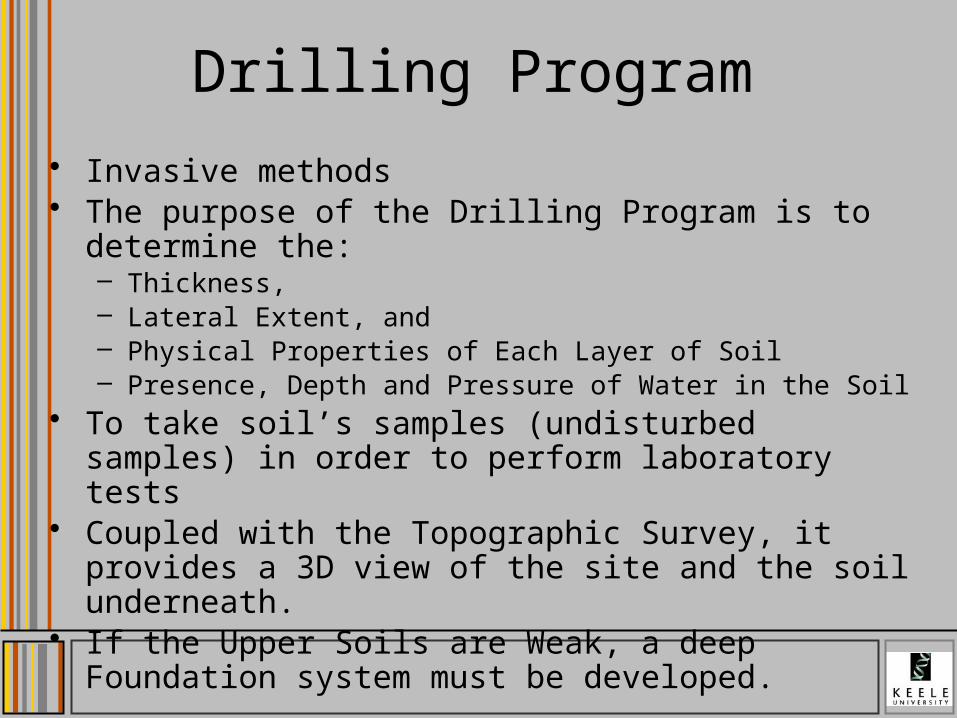
Drilling Program
• Invasive methods• The purpose of the Drilling Program is to determine the:
– Thickness,– Lateral Extent, and– Physical Properties of Each Layer of Soil – Presence, Depth and Pressure of Water in the Soil
• To take soil’s samples (undisturbed samples) in order to perform laboratory tests
• Coupled with the Topographic Survey, it provides a 3D view of the site and the soil underneath.
• If the Upper Soils are Weak, a deep Foundation system must be developed.

Borehole Drilling
• Drilling Rig• Continuous Hollow
Stem Augers With Removable Drill Rod And Center Head

Rough Spacing and Deep Guidelinesfor bore holes testings
Soil Type
Structure Footprint Area / Boring (min)
Depth (min)
m2 m
Poor Quality 100 - 300 6 (S)0.7+D
Average 200 - 400 5 (S)0.7+D
High Quality 300 - 1000 3 (S)0.7+DSource: Coduto, 1999

Raising 70 lb Weight Conventionally 140 lb Weight is Used)
Proper Technique of Releasing the Weight to Reduce Pulley Friction
Standard Penetration (SPT)Penetration Number, N
30
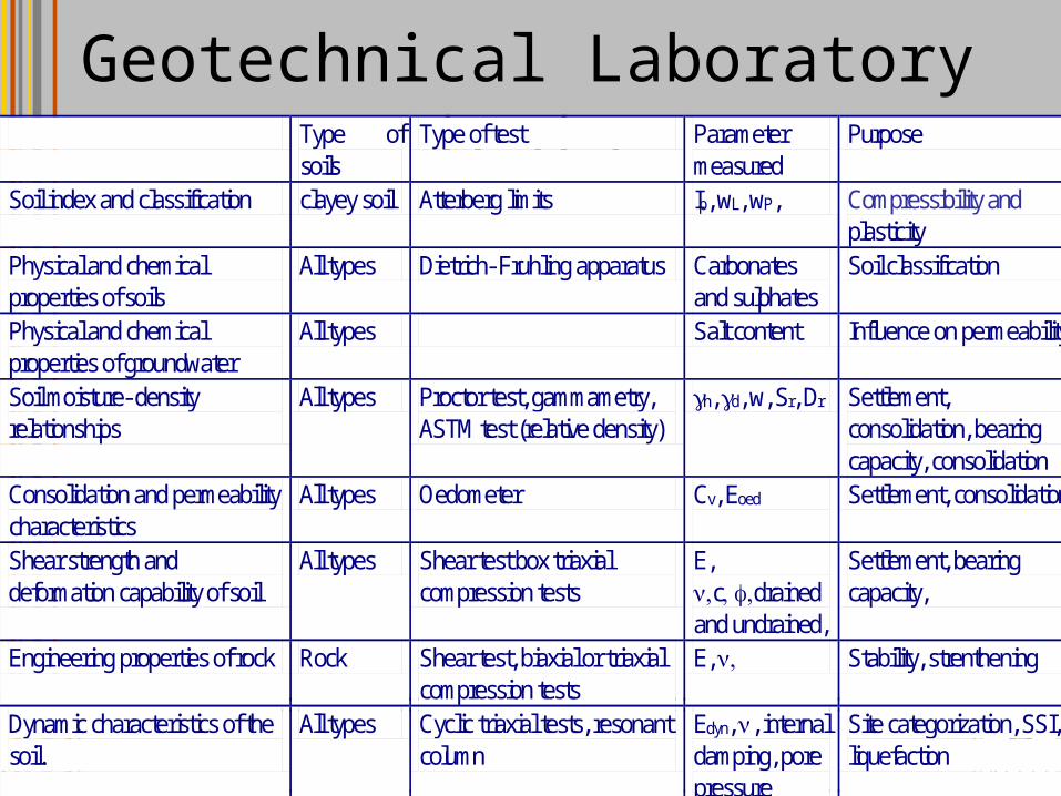
Geotechnical Laboratory tests Type of
soils Type of test Parameter
measured Purpose
Soil index and classification clayey soil Atterberg limits Ip, wL, wP, Compressibility and plasticity
Physical and chemical properties of soils
All types Dietrich- Fruhling apparatus Carbonates and sulphates
Soil classification
Physical and chemical properties of groundwater
All types Salt content Influence on permeability
Soil moisture- density relationships
All types Proctor test, gammametry, ASTM test (relative density)
h, d, w, Sr, Dr Settlement, consolidation, bearing capacity, consolidation
Consolidation and permeability characteristics
All types Oedometer Cv, Eoed
Settlement, consolidation
Shear strength and deformation capability of soil
All types Shear test box triaxial compression tests
E, cdrained and undrained,
Settlement, bearing capacity,
Engineering properties of rock Rock Shear test, biaxial or triaxial compression tests
E, Stability, strenthening
Dynamic characteristics of the soil.
All types Cyclic triaxial tests, resonant column
Edyn, , internal damping, pore pressure
Site categorization, SSI, liquefaction


32
Contents
•Introduction• Site investigation •Site considerations •Foundation Considerations •Earth structures •Buried structures •Monitoring of geotechnical parameters• Quality insurance

33
Bed-rock
-0,04
-0,02
0,00
0,02
0,04
0 10 20 30 40 50 60
Time [sec.]
Ac
ce
lera
tio
n [
g]
Soilprofile
Stability of slopesSoilLiquéfaction
Free field responsespectrum
Vs, ρ, G, DBuriedstructures
Safety related topics to be examined
Soil-StructureInteraction
Bearing capacitySettlements,
Stability

34
The profile • Geometrical description, such as subsurface stratigraphic descriptions, lateral and vertical extent, number and thickness of layers,• Physical and chemical properties of soil and rock and their values used for classification,•S - and P - wave and other mechanical properties obtained by in situ test;•Mechanical properties parameters, stress-strain relationships, static and dynamic strength properties obtained by laboratory tests,•Groundwater table,

35
Site response Modeling
The following model of soil is acceptable:• A viscoelastic soil (materials that dissipate energy by internal damping) system overlying a viscoelastic half-space,• A horizontally layered system ,• Vertically propagating body waves (shear and compression waves), • Non-linear effects may be approximated by equivalent linear methods.
The equivalent linear model (s) of soil constitutive relationship should be consistent with the strain level induced in the soil profile by the response to the input ground motion. This leads generally to an iterative process.• Softwares available: SHAKE, CYBERQUAKE …

Difficult Soils or Conditions
• Karst geology• Liquefaction potential• Compressible/soft soils• Collapsible soils• Expansive soils• Frost-susceptible soils• Specification

37
Contents
•Introduction• Site investigation •Site considerations •Foundation Considerations •Earth structures •Buried structures •Monitoring of geotechnical parameters• Quality insurance

38
Foundations considerations
•Foundation work –Preliminary foundation work –Improvement of foundation conditions –Choice of foundation system and construction
•Soil-structure interaction –Static Analysis , Dynamic Analysis , Analysis methods
•Stability–Bearing capacity , Overturning , Sliding
•Settlements and heaves –Static analysis , Dynamic analysis
•Induced vibration effects

39
Site Preparation & Earthwork
• Site preparation– remove pavements, organics– abandon utilities– abandon/remove old foundations– overexcavation
• Earthwork– compaction requirements– acceptable fill materials

40
Improvement of Foundation Conditions
•Improvement of the foundation conditions should be carried out when:
–The foundation material is not capable of carrying the building loads with acceptable deformation (settlements)–There are cavities that can lead to subsidence –There are heterogeneities, on the scale of building size, which can lead to tilting and/or unacceptable differential settlements–Expansive soil or collapsing soil, sensitive clay or dispersive clay–Site susceptible to liquefaction–Slope instability–Seepage problems

41
Choice of Foundation System
•Two systems of foundations are available for transmitting the superstructure loads to the soil: shallow foundations and deep foundations and the criteria leading to the choice are :
–the forces due to the structures should be transmitted to the soil without any unacceptable deformation,–the soil deformations induced by the earthquake should be compatible with the design requirements of the structure,
•Uncertainties of the seismic response evaluation should be considered in the design and construction of the foundation system• One single type of foundation should be used per structure• The choice of the type of foundation depends on the type of building. Basemat should be used for nuclear island because:
– provides homogeneous settlements under static and dynamic loads – barrier between the environment and the buildings inside

42
CONTENTS
•Introduction• Site investigation •Site considerations •Foundation Considerations •Earth structures •Buried structures •Monitoring of geotechnical parameters• Quality insurance

43
Natural Slopes
• It is important to differentiate potentially hazardous slopes depending on distance to NPP, slope angle, height, geology, water content and other geotechnical conditions of slope material,• External effects of earthquakes and heavy rain-falls should be considered in assessing the potential hazard ,•A stability analysis should be made considering the seismic effect as an equivalent static inertia force; the safety factor should be equal or larger than 1.5 ,• If the safety factor thus evaluated is low enough to indicate a potential for a major sliding failure, a countermeasure for strengthening the slope or preventing the debris from reaching the safety related structures should be designed .

44
Dikes and Dams
• Dikes : structures running along courses of water, • Dams: earth structures higher than 15m, • Special attention should be paid to the permeability of the site close to the areas of the foundations,• The design of dikes and dams in term of safety, should be consistent with the design of NPP (natural hazards ) and consistent with the international regulations for design of dams issued by ICOLD (International Commission on Large Dams• In the design of earth structures two important phenomena should be considered :
–the pore pressure inside the embankment ,–the internal erosion which is caused by water flows inside the embankment.

45
Sea-walls, Breakwaters• Sea-walls, breakwaters, revetments are civil engineering structures to protect NPP against wave action of an ocean or a lake during storms and tsunami,• These structures should be properly designed so that they can prevent soil erosion, floodings and structural failures, and the sustainability of safety functions should be properly evaluated,• Material properties of sea-walls, breakwaters, revetments and backfill materials which include concrete blocks, rubbles and other large size particles should be properly estimated,•The failure consequences on these structures on safety related ducts, pipes and other underground facilities (side-effects) passing near or through the facilities should be appropriately considered.

46
Contents
•Introduction• Site investigation •Site considerations •Foundation Considerations •Earth structures •Buried structures •Monitoring of geotechnical parameters• Quality insurance

47
Buried Structures
•Retaining walls –Gravity walls –Embedded walls (as sheet walls)
•Embedded structures –The interaction of the underground walls with the surrounding ground is significant –Effects of groundwater on embedded structures should be taken into account in design (leaks )– The effects of embedment on impedance of the foundation and on soil-structure interaction should be taken into account if the backfill has been compacted according to the state of the art.
48
Buried Pipes, Conduits & Tunnels
•Investigation program– to identify areas of discontinuities or changes in the foundation material along the route of the pipe ,
•Construction Considerations –sufficient depth to prevent damage due to surface loading (e.g. traffic loads) or alternatively should be designed,–well-compacted granular material over competent foundation material such that no damage or distortion of the piping ,
•Design Considerations –Long, buried piping systems are primarily subjected to relative displacement-induced strains (rather than inertial effects ),–These strains are induced primarily by seismic wave passage and by differential displacement between a building attachment point (anchor point) and the ground surrounding the buried piping ,

49
Buried Pipes, Conduits & Tunnels (ctd)
•Analysis Considerations – Relative deformations imposed by seismic waves travelling through the surrounding soil or by differential deformations between the soil and anchor points,–Lateral earth pressures acting on the cross section,–Intersections move with the surrounding soil and that there is no movement of the buried structure relative to the surrounding soil. –Axial deformations which depends on the wave type ,–Forces and strains due to the maximum relative movement between ,–For deep tunnels and shafts, hoop stresses and strains developed by travelling seismic waves should be considered in the design,

50
Monitoring of Geotechnical Parameters
•Purpose of Monitoring –provide parameters and site characteristics suitable for predicting the performance of foundation systems under various loading conditions.–The monitoring of actual loads and deformations permits a field check of the predicted behavior of the foundations and earth structures
•Guidelines for Monitoring–The soil behavior should be monitored during excavation, backfilling and building construction. –The groundwater regime under buildings and in adjoining areas should be monitored –The monitoring devices should be carefully chosen so that the monitoring system provides the expected information for the life duration of the installation. The choice and number of the devices should rely on feedback experience with regards to their expected failure ratio.

51
QUALITY ASSURANCE
• A Quality Assurance program should be established to control the execution of the site investigations and assessments and engineering activities being performed during the different stages of the site evaluation activities for the NPP.•This program should cover the organization, planning, work control, personnel qualification and training, verification and documentation of the activities.• This program should be established at the earliest possible time consistent with the site evaluation activities for the NPP .•The process of establishing site related parameters and evaluations involves technical and engineering analyses and judgments which requires extensive experience and knowledge .