dr rk bajpai head, repository engineering section bhabha ... · long term strategy spent fuel used...
TRANSCRIPT
Dr RK BajpaiHead,Repository Engineering SectionNuclear Recycle GroupBhabha Atomic Research CenterIndia
IAEA TM on Strategies and Opportunities for the Management of Spent FuelGCNEP, India, 25th-29th November, 2019

Long Term Strategy
Spent Fuel Used As A Resource Material
Long term strategy for HLW in India, is to
separate minor actinides & long lived fission
products
Reducing the need for their long term isolation
Such a strategy also favors recovery of useful
fission products (Cs-137,Ru-106,Y-90,Sr-90)
Novel matrices for immobilization of separated
radionuclide
Transmutation of long lived radionuclide
based on availability of state of art technology

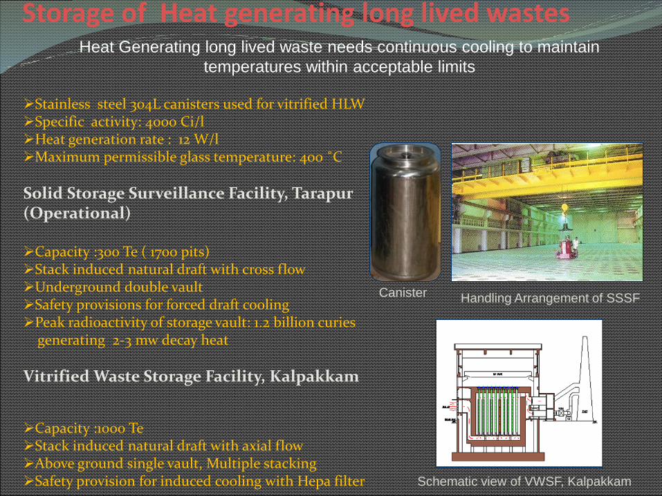
Storage of Heat generating long lived wastes
Stainless steel 304L canisters used for vitrified HLWSpecific activity: 4000 Ci/lHeat generation rate : 12 W/lMaximum permissible glass temperature: 400 ˚C
Solid Storage Surveillance Facility, Tarapur(Operational)
Capacity :300 Te ( 1700 pits)Stack induced natural draft with cross flowUnderground double vaultSafety provisions for forced draft coolingPeak radioactivity of storage vault: 1.2 billion curies
generating 2-3 mw decay heat
Vitrified Waste Storage Facility, Kalpakkam
Capacity :1000 TeStack induced natural draft with axial flowAbove ground single vault, Multiple stackingSafety provision for induced cooling with Hepa filter
Canister
Handling Arrangement of SSSF
Heat Generating long lived waste needs continuous cooling to maintain
temperatures within acceptable limits
Schematic view of VWSF, Kalpakkam
Canister

Low Level RW Disposal Co-location of NSDF with NPP sites Safety periods/Institutional Control : 300 years Discharge of Radioactivity to Environment In Line with Principle of as Low
as Reasonably Achievable.
High Level RW Disposal India recognize the need of a DGR as final solution for permanent disposal of
long lived HLW and other waste A dedicated unit responsible for DGR and associated R&D has been created in
BARC as early as 1980 DGR requirement is slated after few decades Indian DGR is a Central Facility designed and developed to receives waste from
all its nuclear installations Granite host rocks in depth range of 500-700m have been given priority as host
rock/other host rocks also exist. DGR with a capacity of 10000 HLW loaded overpacks is under consideration
with provision to expand it further Very large scale involvement of national expertise in DGR Project Involvement of stakeholders/pubic awareness Participation in international collaborations/IAEA
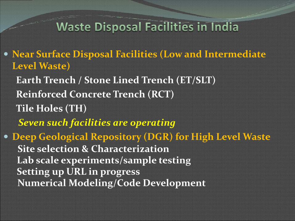
Near Surface Disposal Facilities (Low and Intermediate Level Waste)
Earth Trench / Stone Lined Trench (ET/SLT)
Reinforced Concrete Trench (RCT)
Tile Holes (TH)
Seven such facilities are operating
Deep Geological Repository (DGR) for High Level WasteSite selection & CharacterizationLab scale experiments/sample testingSetting up URL in progressNumerical Modeling/Code Development
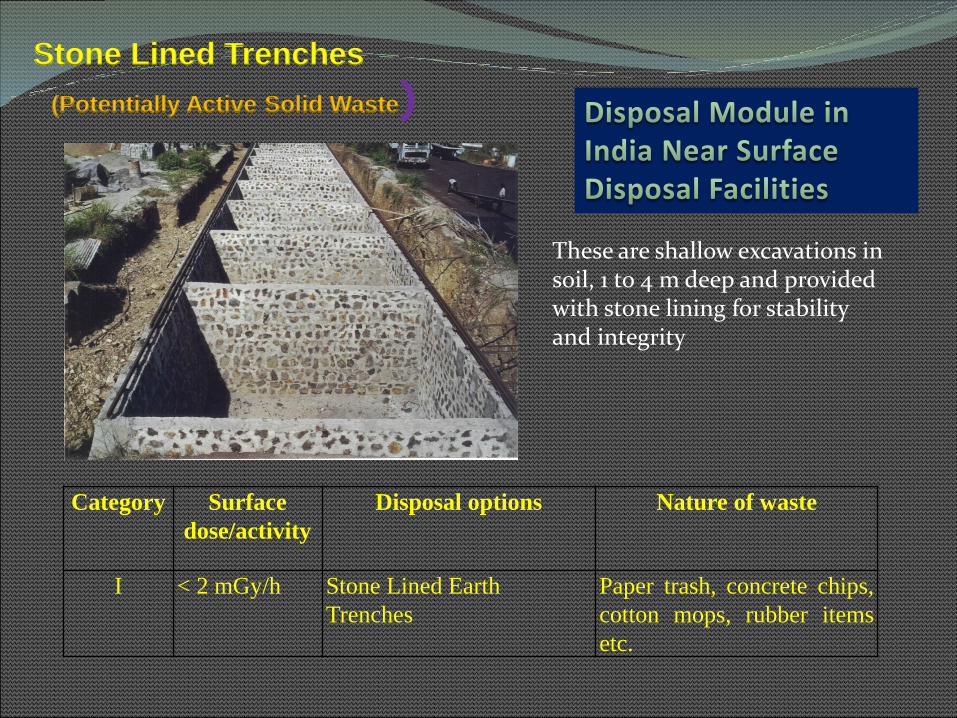
Stone Lined Trenches
(Potentially Active Solid Waste)
Category Surface
dose/activity
Disposal options Nature of waste
I < 2 mGy/h Stone Lined Earth
Trenches
Paper trash, concrete chips,
cotton mops, rubber items
etc.
These are shallow excavations in soil, 1 to 4 m deep and provided with stone lining for stability and integrity

RCC Trenches
2-20 mGy/h RC
Trenches
Contaminated
equipment,
hardware and
filters.
20-500 mGy/h RC
Trenches
Conditioned/pr
ocessed
concentrates,
sludges, spent
resins.
A typical trench is 4.8 m deep, 2.5 m wide and 15 m long. The outer containment wall thickness varies from 350 mm at the top to 750 mm at the bottom

Tile Holes
III >500 mGy/h Tile Holes Hardware from reactors,highly contaminatedequipment, conditionedspent resins etc.
IV Waste bearing alpha activity (< 4000 Bq/g)(> 4000 Bq/g)
RC Trench and Tile HolesTile Holes
Solidified alpha waste with activity.
Circular vaults, nearly 4 m below ground level Average inside diameter of 710mm. Made of 6 mm thick carbon steel shell 25 mm thick concrete lining on both sides

1. DGR should be capable of providing Protection of Health and Environment as
Per Regulatory Requirements ( Time scale: tens of thousands of years)
2. Design is KBS type with canister disposal in vertical pit mode
3. Allow Safe Handling of Waste Over packs ( transfer to 500m depth) &
Accommodate Variety of Waste ( ILW/Spent sources/Spent fuel/Vitrified)
4. Minimization of Mechanical, Hydraulic and Geochemical Perturbations
5. Control Release of Radionuclides ( to keep doses within permissible limits)
6. Design Should be Functional Flexible and Reversible ( Retrievability ?)
7. Avoid Site Complexities and Rely on More Simple High Confidence Models
8. Compliance of Operational and Transport Safety
9. The Facility should be economically viable and should not add adversely to cost
of per unit electricity

Deep geological repository at 500+m depth, with four disposal panels, two shafts, 250 disposal tunnels
Host rock : Granites/Argillites
Capacity : 10000 overpacks
Disposal mode : Pit type
Engineered Barrier : Glass-Canister-Overpack-Clay buffers-backfills-cement bulk head
Temp limit : <100 C
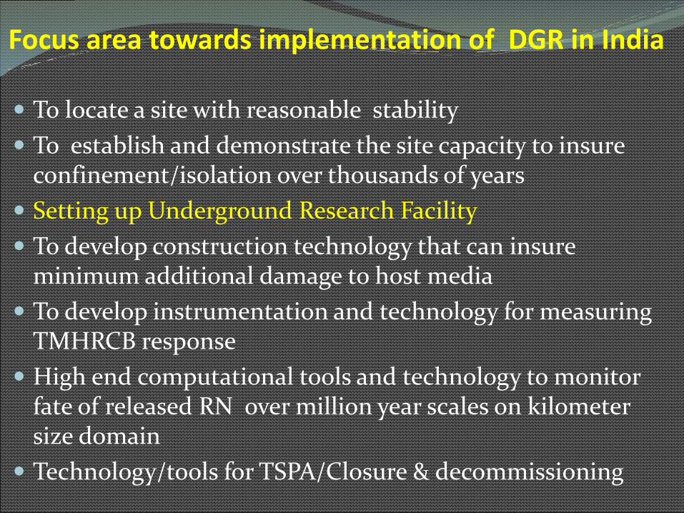
Focus area towards implementation of DGR in India
To locate a site with reasonable stability
To establish and demonstrate the site capacity to insure confinement/isolation over thousands of years
Setting up Underground Research Facility
To develop construction technology that can insure minimum additional damage to host media
To develop instrumentation and technology for measuring TMHRCB response
High end computational tools and technology to monitor fate of released RN over million year scales on kilometer size domain
Technology/tools for TSPA/Closure & decommissioning

Phase Years Activities
Pre Site Selection Studies 2015-2025 Evaluation of Granites/Argillites/Basalts, Lab scale sample characterization and mock up experiments, limited in situ exp. Numerical modeling/Generic URLFinalization of siting methodology
Siting 2025-2030 Geological,geophyical,hydraulicinvestigations and lab based studies
Site characterization/Site Specific URL Phase
2030-2050 In situ experiments to generate site specific data for safety assessment and licensing
Licensing/Regulatoryapprovals/Public Acceptance
2050-2055 Safety cases, approval by regulatory authority, public hearings
Design and Construction 2055-2070 Construction in phases and stages
Operation 2070- Emplacement of waste overpack
Monitoring/Closure
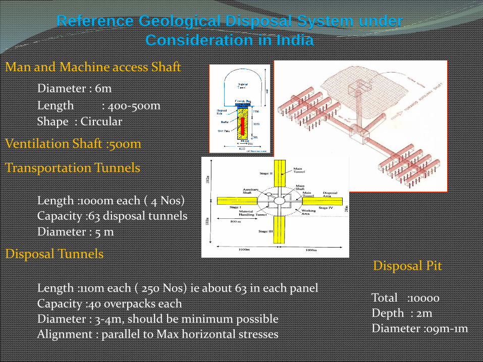
Reference Geological Disposal System under
Consideration in India
Man and Machine access Shaft
Diameter : 6m
Length : 400-500m
Shape : Circular
Ventilation Shaft :500m
Transportation Tunnels
Length :1000m each ( 4 Nos)
Capacity :63 disposal tunnels
Diameter : 5 m
Disposal Tunnels
Length :110m each ( 250 Nos) ie about 63 in each panel
Capacity :40 overpacks each
Diameter : 3-4m, should be minimum possible
Alignment : parallel to Max horizontal stresses
Disposal Pit
Total :10000
Depth : 2m
Diameter :09m-1m
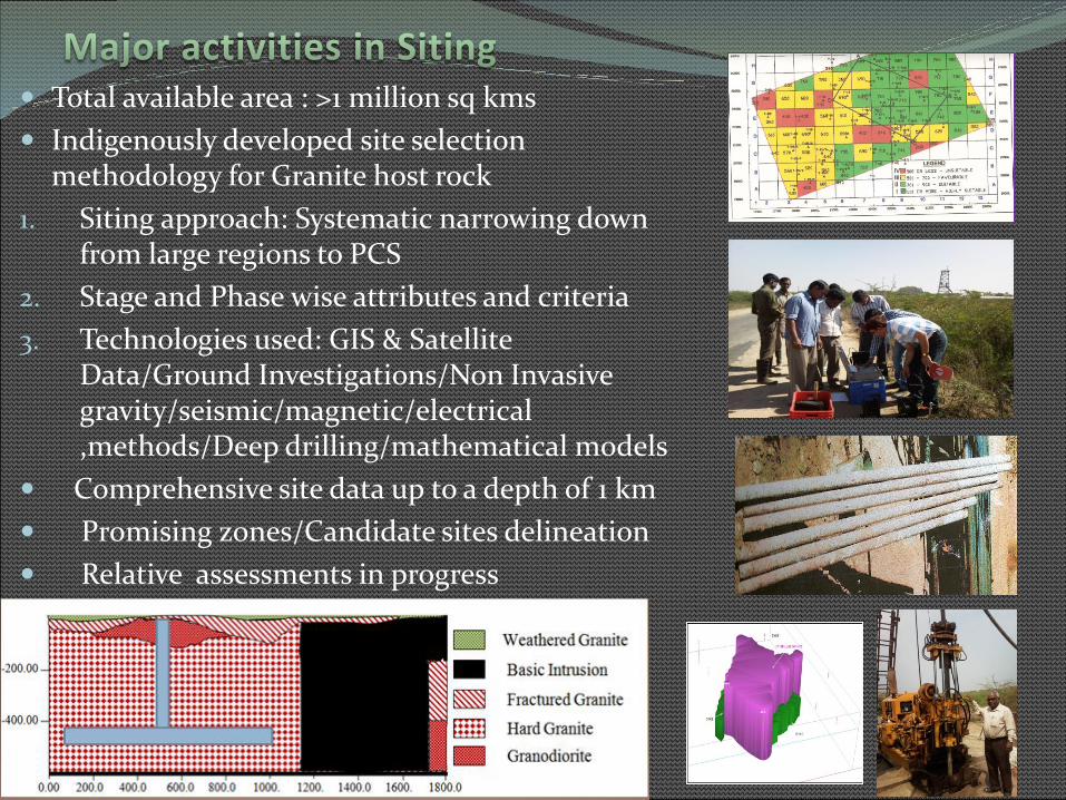
Total available area : >1 million sq kms
Indigenously developed site selection methodology for Granite host rock
1. Siting approach: Systematic narrowing down from large regions to PCS
2. Stage and Phase wise attributes and criteria
3. Technologies used: GIS & Satellite Data/Ground Investigations/Non Invasive gravity/seismic/magnetic/electrical ,methods/Deep drilling/mathematical models
Comprehensive site data up to a depth of 1 km
Promising zones/Candidate sites delineation
Relative assessments in progress
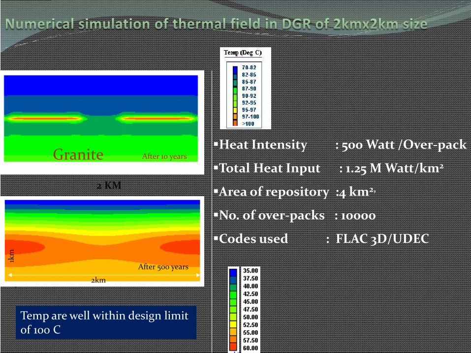
Heat Intensity : 500 Watt /Over-pack
Total Heat Input : 1.25 M Watt/km2
Area of repository :4 km2,
No. of over-packs : 10000
Codes used : FLAC 3D/UDEC
2 KM
After 10 yearsGranite
After 500 years
1km
2km
Temp are well within design limit of 100 C
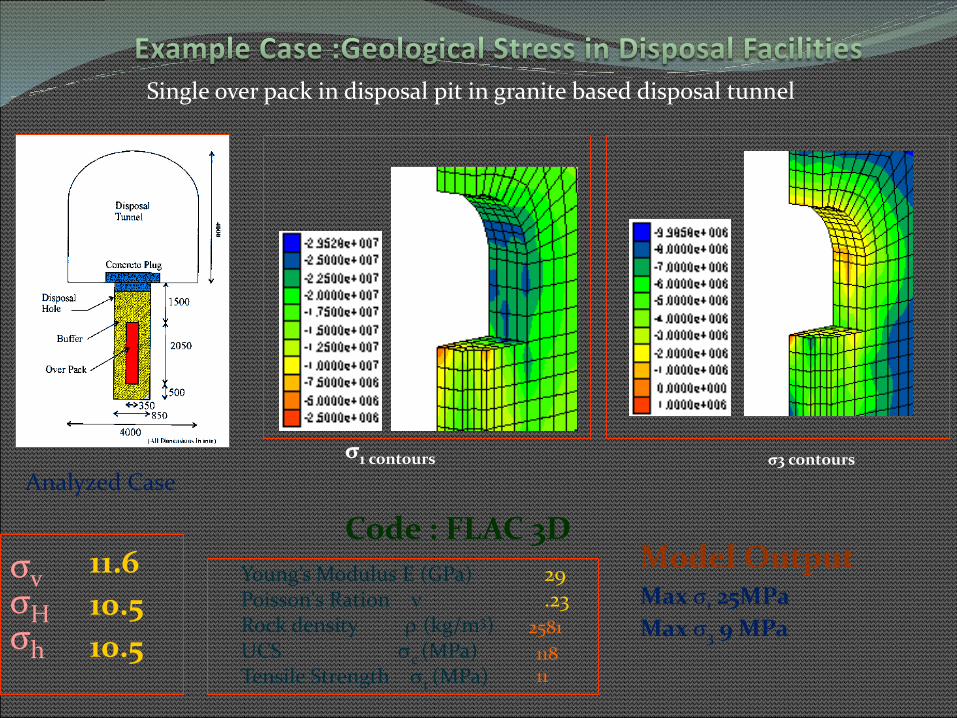
σ1 contours
Young’s Modulus E (GPa) Poisson's Ration Rock density (kg/m3) UCS c (MPa) Tensile Strength t (MPa)
29.23
2581
118 11
σ3 contours
σvσH σh
11.6
10.5
10.5
Code : FLAC 3DModel OutputMax σ1 25MPa
Max σ3 9 MPa
Single over pack in disposal pit in granite based disposal tunnel
Analyzed Case

FLAC3D 2.00
Central Mining Research InstituteRegional Centre, Roorkee
Step 8787 Model Perspective16:46:49 Wed May 14 2003
Center: X: 3.464e-001 Y: -9.921e-001 Z: 7.310e-001
Rotation: X: 10.000 Y: 0.000 Z: 50.000
Dist: 5.536e+002 Mag.: 19.5Ang.: 22.500
Contour of Temperature 7.8184e+001 to 8.2500e+001 8.2500e+001 to 8.5000e+001 8.5000e+001 to 8.7500e+001 8.7500e+001 to 9.0000e+001 9.0000e+001 to 9.2500e+001 9.2500e+001 to 9.5000e+001 9.5000e+001 to 9.7500e+001 9.7500e+001 to 1.0000e+002 1.0000e+002 to 1.0171e+002
Interval = 2.5e+000
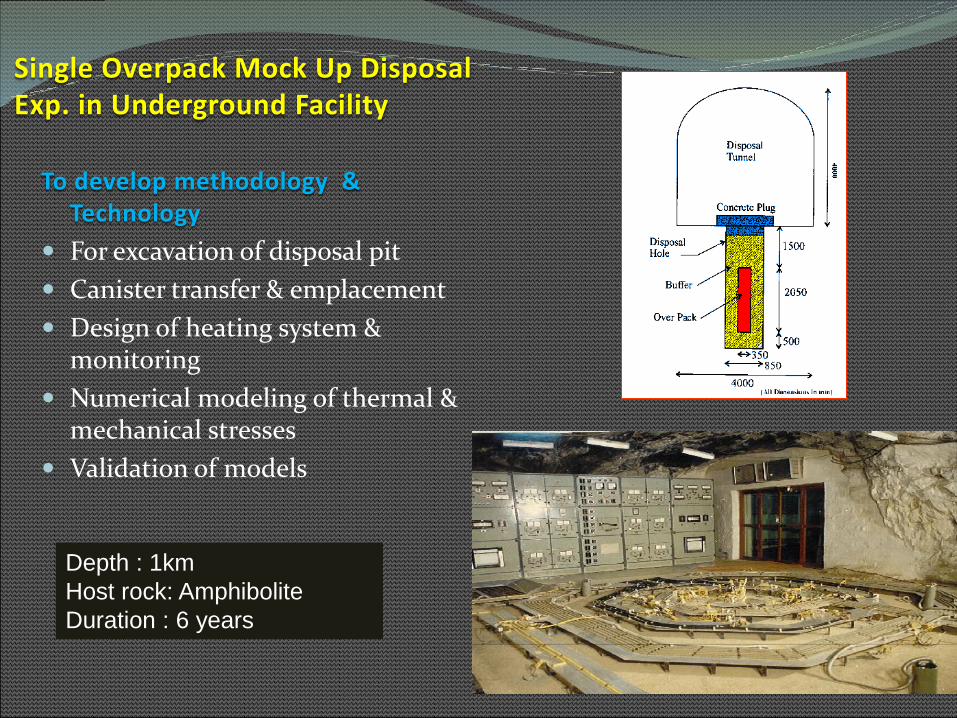
Single Overpack Mock Up Disposal Exp. in Underground Facility
To develop methodology & Technology
For excavation of disposal pit
Canister transfer & emplacement
Design of heating system & monitoring
Numerical modeling of thermal & mechanical stresses
Validation of models
Depth : 1km
Host rock: Amphibolite
Duration : 6 years
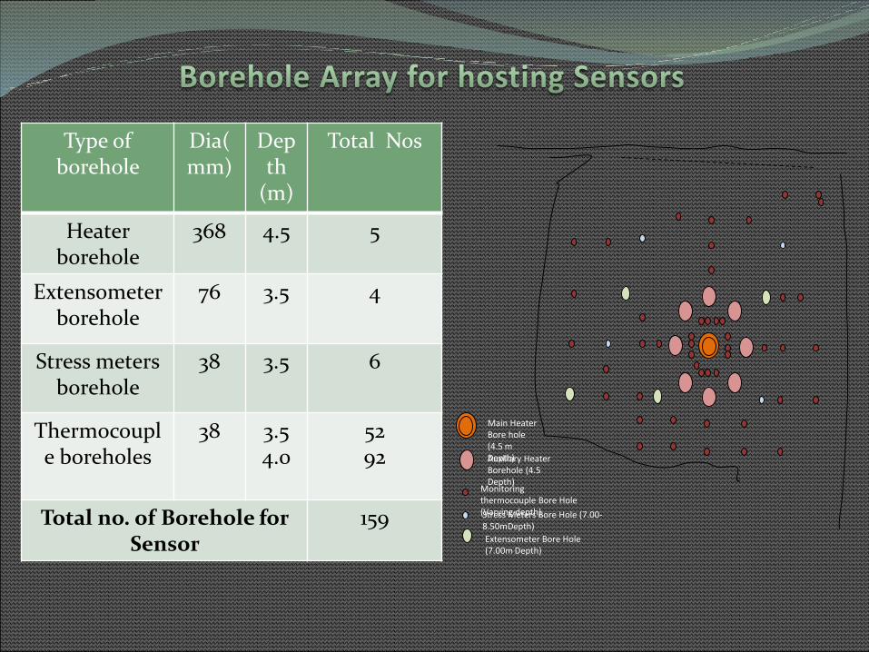
Type of borehole
Dia(mm)
Depth
(m)
Total Nos
Heater borehole
368 4.5 5
Extensometer borehole
76 3.5 4
Stress meters borehole
38 3.5 6
Thermocouple boreholes
38 3.54.0
5292
Total no. of Borehole for Sensor
159
Main Heater Bore hole (4.5 m Depth)Auxiliary Heater Borehole (4.5 Depth)
Monitoring thermocouple Bore Hole (Varying depth)Stress Meters Bore Hole (7.00-8.50mDepth)
Extensometer Bore Hole (7.00m Depth)
Amphibolite Rock
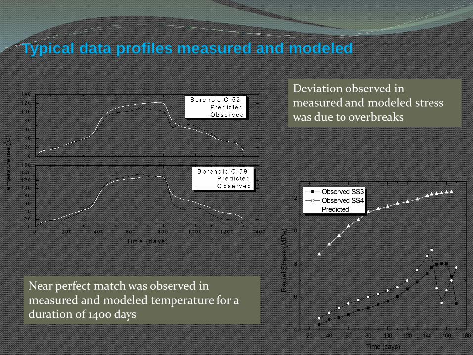
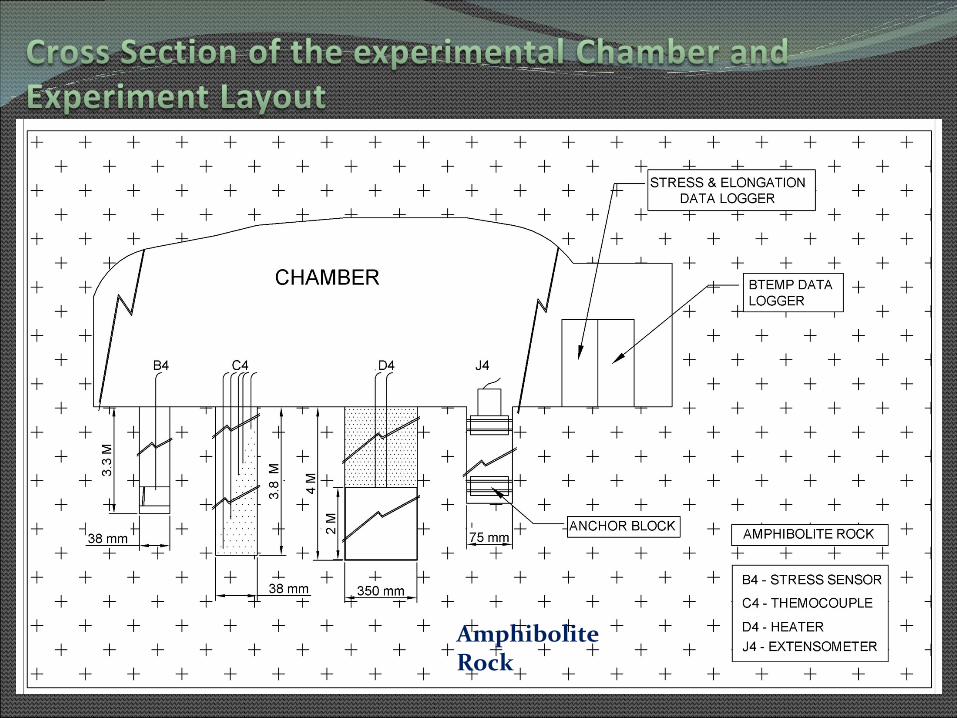
Typical data profiles measured and modeled
Near perfect match was observed in measured and modeled temperature for a duration of 1400 days
Deviation observed in measured and modeled stress was due to overbreaks

•Canister transfer/emplacement• Long term TMRCHB response measurement/monitoring•Single overpack/Multiple overpacks experiments•Disposal Gallery Scale Experiment and demonstration•Proto type repository demonstration•Characterization method development
•Develop geological characterization methods /In situ stress/Hydraulic permeability measurement /Hydrogeological characterization methods
•Solute Transport/Gas Migration Studies for Safety Assessments•Parameters, mechanism, controls, modeling/RN Transport on cm, m and Deca meter natural fractures
•Design and Construction of Repository •Measurement of Excavation Damage Zone (EDZ)/Methodology to minimize EDZ/Development of Non blast excavation methods•Excavation methodology for large diameter disposal pits
•Pathway Sealing Experiments•Grouting experiments/Integrated tunnel sealing experiments•Excavation Damage Zones (EDZ) treatment


1) Hydration System
2) Heating System
3)Granite-Clay Barrier-Heater
4)Thermo- Hydro mechanical
instrumentation
5) DAS and HCS
To study complex thermal-hydraulic-mechanical-geochemical interaction among granite-clay-groundwater-waste canister
In progress

Excavation Response around disposal pits/galleries/shaft of DGR
Thermal Response around single canisters/multiple canisters
Radio Nuclide Transport through granites/smectite clays
Geochemical Modeling of glass, clay alteration
Coupled Mechanical, Thermal , Hydraulic Processes
Pre Experiment Modeling of lab and field scale experiments
Important themes and Ongoing studies
Codes in use: FLAC,3DEC,Modflow,Feeflow,Amber,Phase-II,Examine 3D and in-house lattice Bolzman method based codes on reactive transport

Current Focus Area
1 DGR/site evaluation/Lab based studies/modeling/identification of promising candidate sites
2 Setting up Underground Research Facility and experimentations
3 Investigations, design, analysis, costing, formulation of experiments etc
4 Development of analysis codes for Radionuclide transport, TMH coupling/Reactive transport
5 Development of Clay barriers for use in waste disposal facilities
6 Meter scale TMH Experiment to simulate disposal pit of DGR for design of Full Scale Exp
7 Alternate host rock TMH characterization to broaden the scope of final site selection
8 Sorption of actinides and FP on host rocks/clay barriers for use in safety assessments/petro mineralogy studies
9 Stability assessment under earthquake for improving design of underground excavations
10 Gas migration experiment through EBS for material qualifications/safety assessments
11 Long term performance assessment of clay barriers/glasses/Natural analgoues
