draeger polytron ir 334 programmable serial interface card ... drivers... · powerful solutions for...
TRANSCRIPT
Draeger Polytron IR 334 Programmable Serial Interface Card
Series 2
USER MANUAL
IOD-1179, Rev. P1.10
September 15, 2008
DeltaV is a trademark of Emerson Process Management, Inc © Emerson Process Management, Inc. 1998, 1999. All rights reserved. Printed in the U.S.A. While this information is presented in good faith and believed to be accurate, MYNAH Technologies does not guarantee satisfactory results from reliance upon such information. Nothing contained herein is to be construed as a warranty or guarantee, express or implied, regarding the performance, merchantability, fitness or any other matter with respect to the products, nor as a recommendation to use any product or process in conflict with any patent. MYNAH Technologies reserves the right, without notice, to alter or improve the designs or specifications of the products described herein.

POWERFUL SOLUTIONS FOR DIGITAL PLANTS
MYNAH Technologies ▪ 504 Trade Center Blvd ▪ Chesterfield, MO 63005 ▪ Telephone (636)681-1555 ▪ Fax (636) 681-1660
www.mynah.com
1
1 Introduction
1.1 Scope
This document is user manual for IOD-1179, the Draeger Polytron IR 334 communications driver firmware for the Emerson Process Management (EPM) DeltaV Control System. The driver runs in the DeltaV Series 2 Programmable Serial Interface Card (PSIC). The reader should be familiar with EPM’s DeltaV PSIC and connected Draeger devices.
1.2 Document Format
This document is organized as follows:
Introduction Describes the scope and purpose of this document.
Theory of Operation Provides a general functional overview of the Draeger Polytron Driver.
Downloading Firmware Describes downloading procedures for the driver firmware on to the DeltaV PSIC.
Configuration Information Describes procedures and guidelines for configuring the DeltaV PSIC.
Displaying Dynamic Data from the Draeger Polytron device
Gives an example of how to display dynamic information from Draeger Polytron devices.
Operational Check Provides tips and assistance to ensure PSIC is properly setup and configured.
DeltaV–Field Device Electrical Interface
Describes the electrical interface between DeltaV and the Draeger devices. Also describes the cable pin assignments for RS-485.
Technical Support Describes who to call if you need assistance.

POWERFUL SOLUTIONS FOR DIGITAL PLANTS
MYNAH Technologies ▪ 504 Trade Center Blvd ▪ Chesterfield, MO 63005 ▪ Telephone (636)681-1555 ▪ Fax (636) 681-1660
www.mynah.com
2
1.3 System Specifications
The following table lists the minimum system requirements for the driver:
Protocol Compatibility and Reference documents
Device communication is based on the HART Field Communications Protocol, as described in Application Guide, HCF LIT 34. In addition, Draeger Polytron specific HART commands used are as documented in “An Introduction to Polytron 2 Transmitter Specific Commands”, Version 2.0, published by Draeger.
Software Requirements DeltaV System Software (Release 6.3.2 or later) installed on a hardware-appropriate Windows workstation configured as a ProfessionalPlus for DeltaV
Serial Interface Port License (VE4102)
Minimum DeltaV Hardware Requirements
FRSI DeltaV Serial Interface Series 2, Hardware PN: 12P2506X022
FRSI DeltaV M3, M5, MD or Series 2 MD Controller, Power Supply and 2 wide controller carrier
FRSI 8 wide I/O card carrier
POWERFUL SOLUTIONS FOR DIGITAL PLANTS
MYNAH Technologies ▪ 504 Trade Center Blvd ▪ Chesterfield, MO 63005 ▪ Telephone (636)681-1555 ▪ Fax (636) 681-1660
www.mynah.com
3
2 Theory of Operation
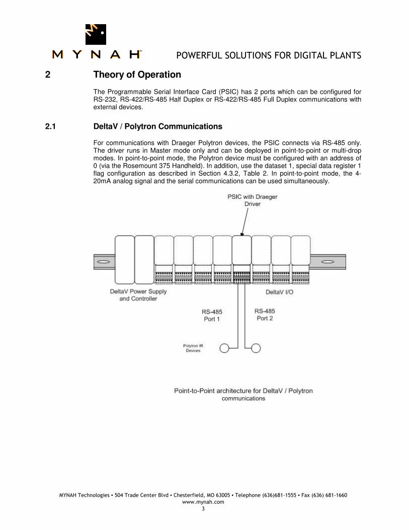
The Programmable Serial Interface Card (PSIC) has 2 ports which can be configured for RS-232, RS-422/RS-485 Half Duplex or RS-422/RS-485 Full Duplex communications with external devices.
2.1 DeltaV / Polytron Communications
For communications with Draeger Polytron devices, the PSIC connects via RS-485 only. The driver runs in Master mode only and can be deployed in point-to-point or multi-drop modes. In point-to-point mode, the Polytron device must be configured with an address of 0 (via the Rosemount 375 Handheld). In addition, use the dataset 1, special data register 1 flag configuration as described in Section 4.3.2, Table 2. In point-to-point mode, the 4-20mA analog signal and the serial communications can be used simultaneously.
POWERFUL SOLUTIONS FOR DIGITAL PLANTS
MYNAH Technologies ▪ 504 Trade Center Blvd ▪ Chesterfield, MO 63005 ▪ Telephone (636)681-1555 ▪ Fax (636) 681-1660
www.mynah.com
4
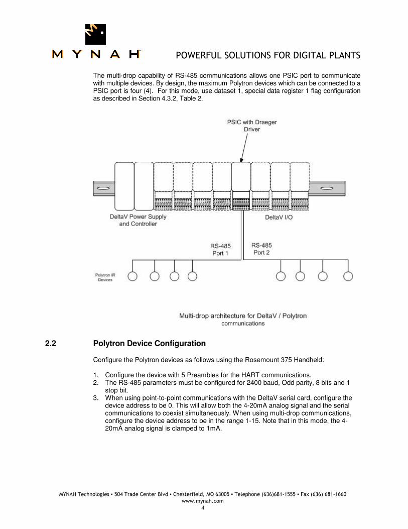
The multi-drop capability of RS-485 communications allows one PSIC port to communicate with multiple devices. By design, the maximum Polytron devices which can be connected to a PSIC port is four (4). For this mode, use dataset 1, special data register 1 flag configuration as described in Section 4.3.2, Table 2.
2.2 Polytron Device Configuration
Configure the Polytron devices as follows using the Rosemount 375 Handheld: 1. Configure the device with 5 Preambles for the HART communications. 2. The RS-485 parameters must be configured for 2400 baud, Odd parity, 8 bits and 1
stop bit. 3. When using point-to-point communications with the DeltaV serial card, configure the
device address to be 0. This will allow both the 4-20mA analog signal and the serial communications to coexist simultaneously. When using multi-drop communications, configure the device address to be in the range 1-15. Note that in this mode, the 4-20mA analog signal is clamped to 1mA.

POWERFUL SOLUTIONS FOR DIGITAL PLANTS
MYNAH Technologies ▪ 504 Trade Center Blvd ▪ Chesterfield, MO 63005 ▪ Telephone (636)681-1555 ▪ Fax (636) 681-1660
www.mynah.com
5
3 Downloading the firmware
The driver software distribution comprises 15 files, distributed on a CD. These files must be copied to the DeltaV directory on your ProPlus Workstation. The path is: \DeltaV\ctl\ProgSerial\Draeger
Note that you will have to create the \Draeger subdirectory. The following files will be copied:
POWERFUL SOLUTIONS FOR DIGITAL PLANTS
MYNAH Technologies ▪ 504 Trade Center Blvd ▪ Chesterfield, MO 63005 ▪ Telephone (636)681-1555 ▪ Fax (636) 681-1660
www.mynah.com
6
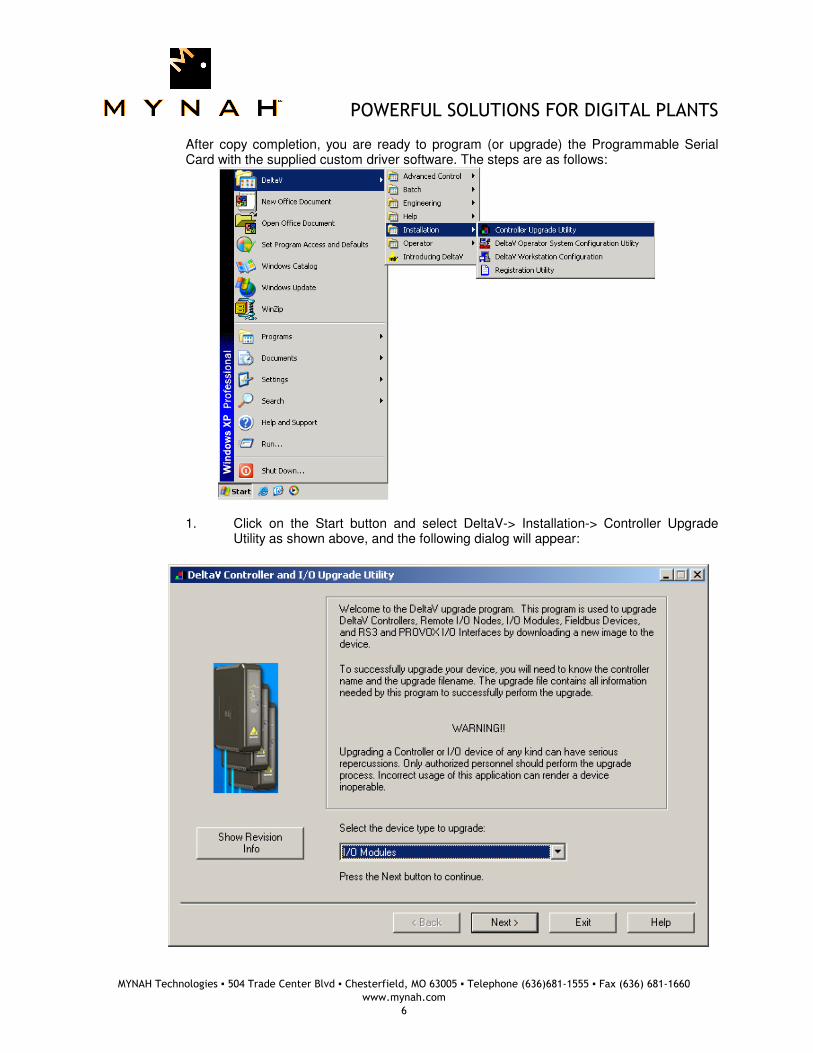
After copy completion, you are ready to program (or upgrade) the Programmable Serial Card with the supplied custom driver software. The steps are as follows:
1. Click on the Start button and select DeltaV-> Installation-> Controller Upgrade Utility as shown above, and the following dialog will appear:
POWERFUL SOLUTIONS FOR DIGITAL PLANTS
MYNAH Technologies ▪ 504 Trade Center Blvd ▪ Chesterfield, MO 63005 ▪ Telephone (636)681-1555 ▪ Fax (636) 681-1660
www.mynah.com
7
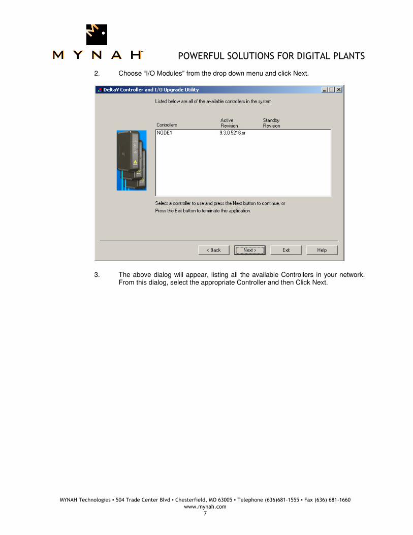
2. Choose “I/O Modules” from the drop down menu and click Next.
3. The above dialog will appear, listing all the available Controllers in your network.
From this dialog, select the appropriate Controller and then Click Next.
POWERFUL SOLUTIONS FOR DIGITAL PLANTS
MYNAH Technologies ▪ 504 Trade Center Blvd ▪ Chesterfield, MO 63005 ▪ Telephone (636)681-1555 ▪ Fax (636) 681-1660
www.mynah.com
8
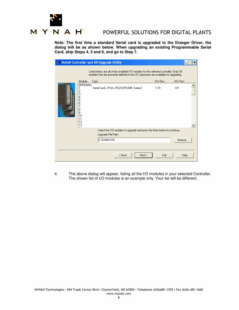
Note: The first time a standard Serial card is upgraded to the Draeger Driver, the dialog will be as shown below. When upgrading an existing Programmable Serial Card, skip Steps 4, 5 and 6, and go to Step 7.
4. The above dialog will appear, listing all the I/O modules in your selected Controller.
The shown list of I/O modules is an example only. Your list will be different.
POWERFUL SOLUTIONS FOR DIGITAL PLANTS
MYNAH Technologies ▪ 504 Trade Center Blvd ▪ Chesterfield, MO 63005 ▪ Telephone (636)681-1555 ▪ Fax (636) 681-1660
www.mynah.com
9
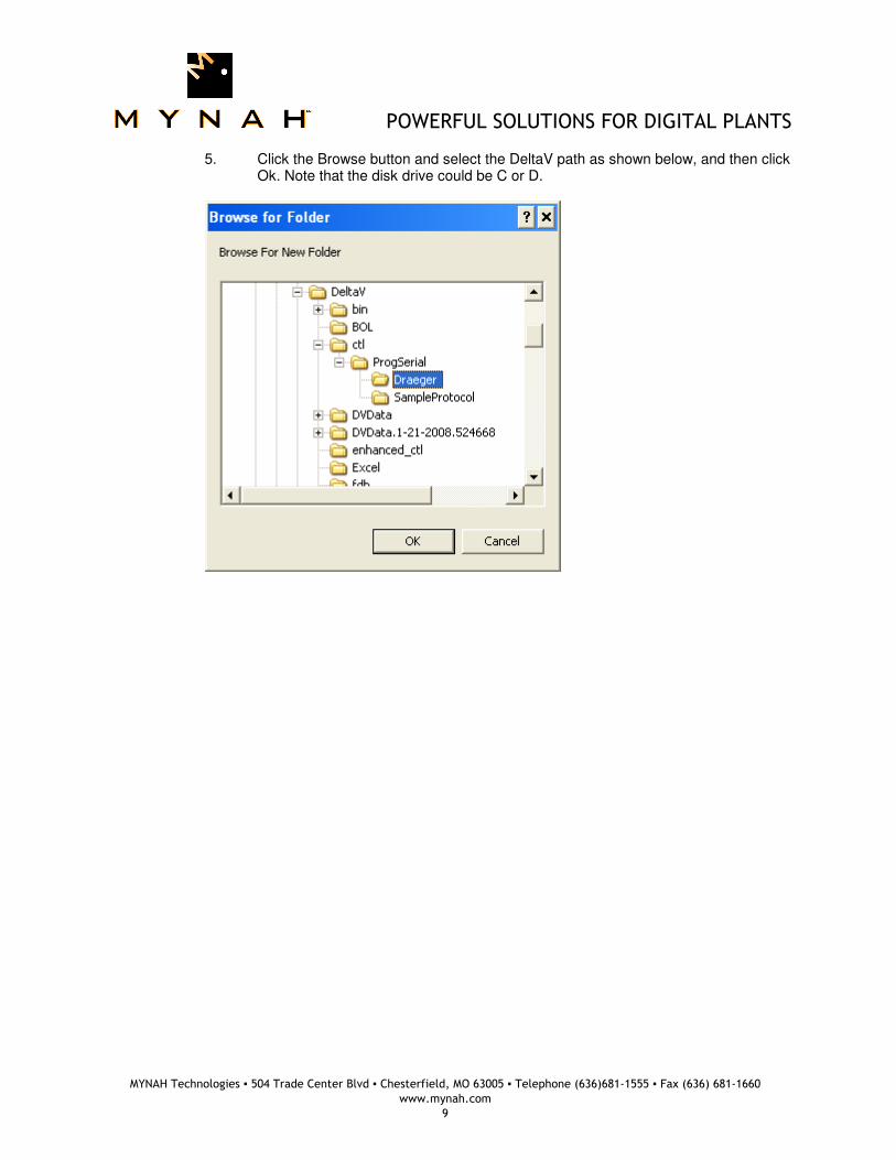
5. Click the Browse button and select the DeltaV path as shown below, and then click Ok. Note that the disk drive could be C or D.
POWERFUL SOLUTIONS FOR DIGITAL PLANTS
MYNAH Technologies ▪ 504 Trade Center Blvd ▪ Chesterfield, MO 63005 ▪ Telephone (636)681-1555 ▪ Fax (636) 681-1660
www.mynah.com
10
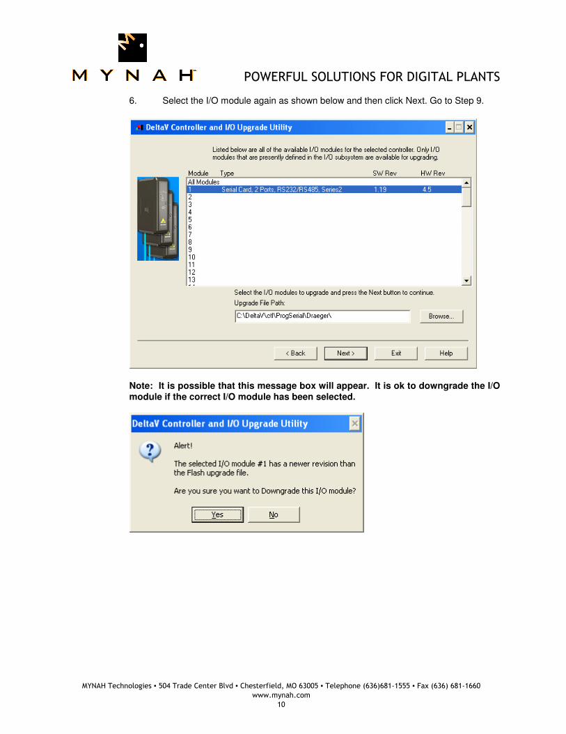
6. Select the I/O module again as shown below and then click Next. Go to Step 9.
Note: It is possible that this message box will appear. It is ok to downgrade the I/O module if the correct I/O module has been selected.
POWERFUL SOLUTIONS FOR DIGITAL PLANTS
MYNAH Technologies ▪ 504 Trade Center Blvd ▪ Chesterfield, MO 63005 ▪ Telephone (636)681-1555 ▪ Fax (636) 681-1660
www.mynah.com
11
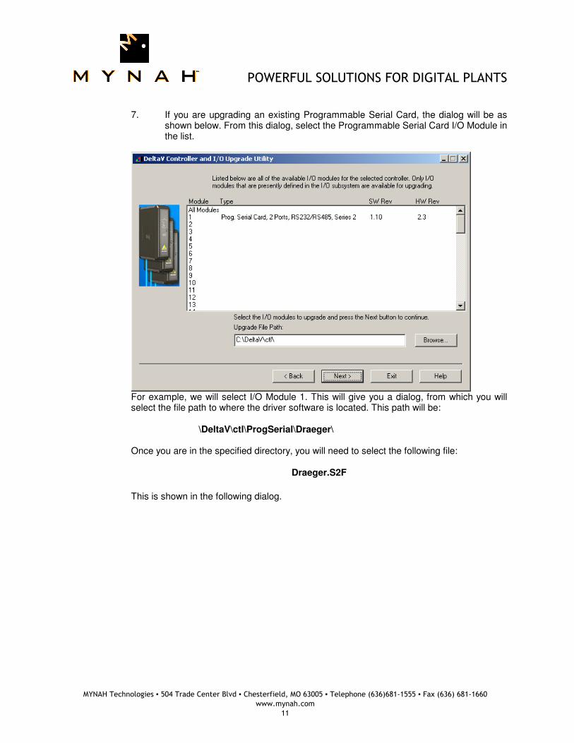
7. If you are upgrading an existing Programmable Serial Card, the dialog will be as
shown below. From this dialog, select the Programmable Serial Card I/O Module in the list.
For example, we will select I/O Module 1. This will give you a dialog, from which you will
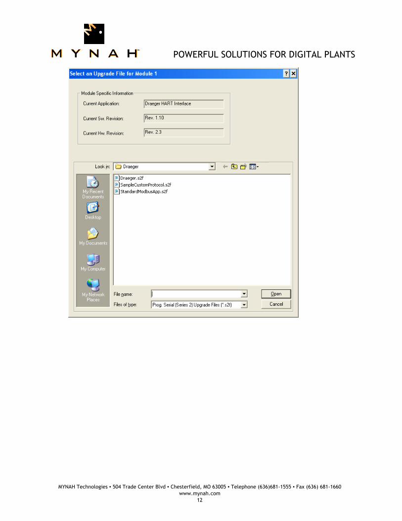
select the file path to where the driver software is located. This path will be: \DeltaV\ctl\ProgSerial\Draeger\ Once you are in the specified directory, you will need to select the following file:
Draeger.S2F
This is shown in the following dialog.
POWERFUL SOLUTIONS FOR DIGITAL PLANTS
MYNAH Technologies ▪ 504 Trade Center Blvd ▪ Chesterfield, MO 63005 ▪ Telephone (636)681-1555 ▪ Fax (636) 681-1660
www.mynah.com
12
POWERFUL SOLUTIONS FOR DIGITAL PLANTS
MYNAH Technologies ▪ 504 Trade Center Blvd ▪ Chesterfield, MO 63005 ▪ Telephone (636)681-1555 ▪ Fax (636) 681-1660
www.mynah.com
13
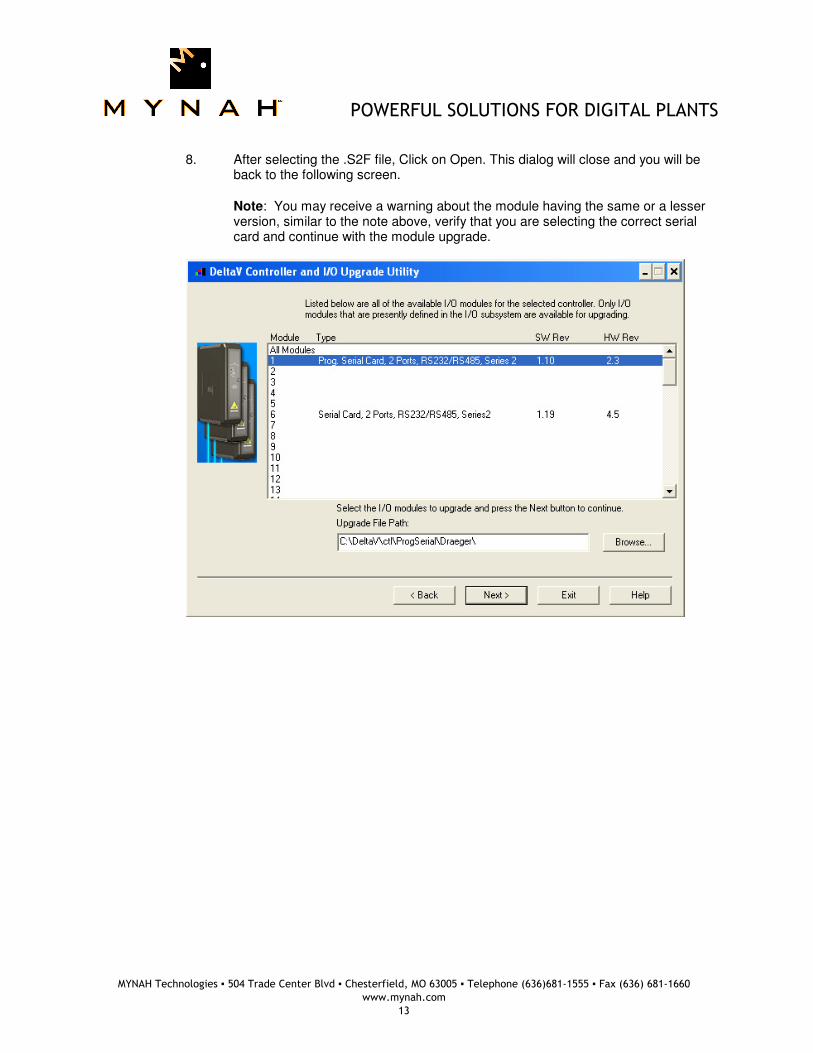
8. After selecting the .S2F file, Click on Open. This dialog will close and you will be
back to the following screen. Note: You may receive a warning about the module having the same or a lesser version, similar to the note above, verify that you are selecting the correct serial card and continue with the module upgrade.
POWERFUL SOLUTIONS FOR DIGITAL PLANTS
MYNAH Technologies ▪ 504 Trade Center Blvd ▪ Chesterfield, MO 63005 ▪ Telephone (636)681-1555 ▪ Fax (636) 681-1660
www.mynah.com
14
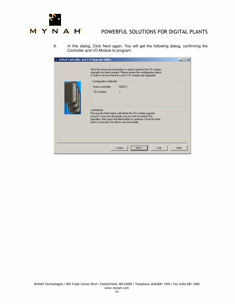
9. In this dialog, Click Next again. You will get the following dialog, confirming the
Controller and I/O Module to program.

POWERFUL SOLUTIONS FOR DIGITAL PLANTS
MYNAH Technologies ▪ 504 Trade Center Blvd ▪ Chesterfield, MO 63005 ▪ Telephone (636)681-1555 ▪ Fax (636) 681-1660
www.mynah.com
15
10. Click Next and the I/O Module upgrade process will begin. After completion, you
will receive the following dialog, indicating success.
11. If this upgrade started with a standard Serial Card, hit the back button and
continue the upgrade procedure from Step 7. Once Steps 7 through 10 have been completed, the upgrade will be complete.
POWERFUL SOLUTIONS FOR DIGITAL PLANTS
MYNAH Technologies ▪ 504 Trade Center Blvd ▪ Chesterfield, MO 63005 ▪ Telephone (636)681-1555 ▪ Fax (636) 681-1660
www.mynah.com
16
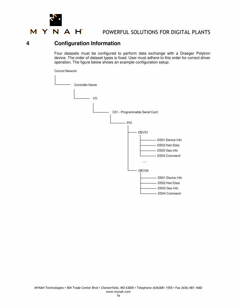
4 Configuration Information
Four datasets must be configured to perform data exchange with a Draeger Polytron device. The order of dataset types is fixed. User must adhere to this order for correct driver operation. The figure below shows an example configuration setup:

POWERFUL SOLUTIONS FOR DIGITAL PLANTS
MYNAH Technologies ▪ 504 Trade Center Blvd ▪ Chesterfield, MO 63005 ▪ Telephone (636)681-1555 ▪ Fax (636) 681-1660
www.mynah.com
17
4.1 Port Configuration
The port should be configured as Master. Transmit delay must be configured as 1000. The Port Type should be defined as RS-485. The Baud Rate, Parity, Data Bits and Stop Bits should match the settings of the Polytron device. It is recommended that the Polytron be configured with 2400 baud, Odd parity, 8 data bits and 1 stop bit.

POWERFUL SOLUTIONS FOR DIGITAL PLANTS
MYNAH Technologies ▪ 504 Trade Center Blvd ▪ Chesterfield, MO 63005 ▪ Telephone (636)681-1555 ▪ Fax (636) 681-1660
www.mynah.com
18
4.2 Device Configuration
One device should be configured for each Polytron connected to a given port. The device address is used in this driver, and should match the device address configured in the Polytron device. The device address must be between 1 and 15. Maximum number of multi-dropped Polytron devices is four (4). In point-to-point mode, the DeltaV device address is ignored. Note: Polytron devices must also be configured with 5 Preambles for the HART communications.
4.3 Dataset Configuration
Four (4) datasets are required for each Polytron device. The Device Data Type of the dataset determines how the dataset is used and which information is contained in it. Datasets must be configured in order.
4.3.1 Data Direction
Table 1 lists the possible Device Data Types and their direction. Table 2 matches the Device Data Type with the DeltaV Data Type and gives the size of the dataset.
4.3.2 Data Type and Size
Configure each device as follows: Table 1 – Device Data Types and Descriptions
DS # DEVICE DATA TYPE
DIRECTION DESCRIPTION
1 0 Input This dataset contains the device information returned in response to HART command 0.
2 1 Input This dataset contains device information returned by HART commands 3, 15, and
3 2 Input This dataset contains the selected gas name, and units. This information is returned by HART command 132
4 3 Output with Readback This is the command dataset. DeltaV Control Modules use R1 of this dataset to select a new gas in the Polytron. R1 also contains the gas selection index read back from the Polytron device.
POWERFUL SOLUTIONS FOR DIGITAL PLANTS
MYNAH Technologies ▪ 504 Trade Center Blvd ▪ Chesterfield, MO 63005 ▪ Telephone (636)681-1555 ▪ Fax (636) 681-1660
www.mynah.com
19
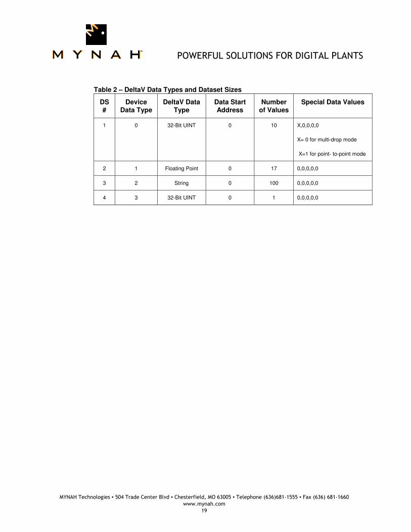
Table 2 – DeltaV Data Types and Dataset Sizes
DS #
Device Data Type
DeltaV Data Type
Data Start Address
Number of Values
Special Data Values
1 0 32-Bit UINT 0 10 X,0,0,0,0
X= 0 for multi-drop mode
X=1 for point- to-point mode
2 1 Floating Point 0 17 0,0,0,0,0
3 2 String 0 100 0,0,0,0,0
4 3 32-Bit UINT 0 1 0,0,0,0,0
POWERFUL SOLUTIONS FOR DIGITAL PLANTS
MYNAH Technologies ▪ 504 Trade Center Blvd ▪ Chesterfield, MO 63005 ▪ Telephone (636)681-1555 ▪ Fax (636) 681-1660
www.mynah.com
20
5 Data Mapping
5.1 Dynamic Data
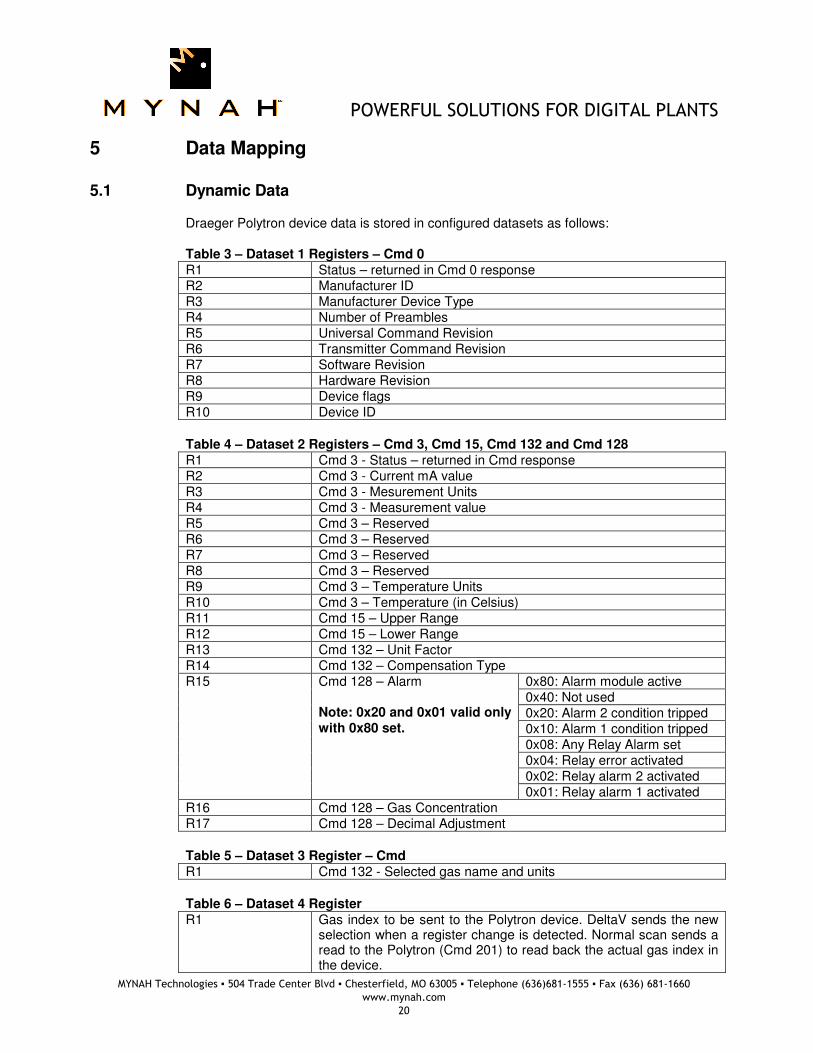
Draeger Polytron device data is stored in configured datasets as follows: Table 3 – Dataset 1 Registers – Cmd 0
R1 Status – returned in Cmd 0 response R2 Manufacturer ID R3 Manufacturer Device Type R4 Number of Preambles R5 Universal Command Revision R6 Transmitter Command Revision R7 Software Revision R8 Hardware Revision R9 Device flags R10 Device ID
Table 4 – Dataset 2 Registers – Cmd 3, Cmd 15, Cmd 132 and Cmd 128
R1 Cmd 3 - Status – returned in Cmd response R2 Cmd 3 - Current mA value R3 Cmd 3 - Mesurement Units R4 Cmd 3 - Measurement value R5 Cmd 3 – Reserved R6 Cmd 3 – Reserved R7 Cmd 3 – Reserved R8 Cmd 3 – Reserved R9 Cmd 3 – Temperature Units R10 Cmd 3 – Temperature (in Celsius) R11 Cmd 15 – Upper Range R12 Cmd 15 – Lower Range R13 Cmd 132 – Unit Factor R14 Cmd 132 – Compensation Type R15 Cmd 128 – Alarm
Note: 0x20 and 0x01 valid only with 0x80 set.
0x80: Alarm module active 0x40: Not used 0x20: Alarm 2 condition tripped 0x10: Alarm 1 condition tripped 0x08: Any Relay Alarm set 0x04: Relay error activated 0x02: Relay alarm 2 activated 0x01: Relay alarm 1 activated
R16 Cmd 128 – Gas Concentration R17 Cmd 128 – Decimal Adjustment
Table 5 – Dataset 3 Register – Cmd
R1 Cmd 132 - Selected gas name and units
Table 6 – Dataset 4 Register
R1 Gas index to be sent to the Polytron device. DeltaV sends the new selection when a register change is detected. Normal scan sends a read to the Polytron (Cmd 201) to read back the actual gas index in the device.
POWERFUL SOLUTIONS FOR DIGITAL PLANTS
MYNAH Technologies ▪ 504 Trade Center Blvd ▪ Chesterfield, MO 63005 ▪ Telephone (636)681-1555 ▪ Fax (636) 681-1660
www.mynah.com
21
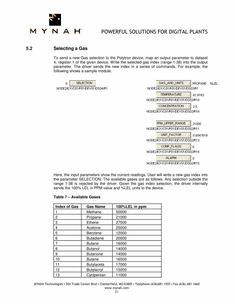
5.2 Selecting a Gas
To send a new Gas selection to the Polytron device, map an output parameter to dataset 4, register 1 of the given device. Write the selected gas index (range 1-38) into the output parameter. The driver sends the new index in a series of commands. For example, the following shows a sample module:
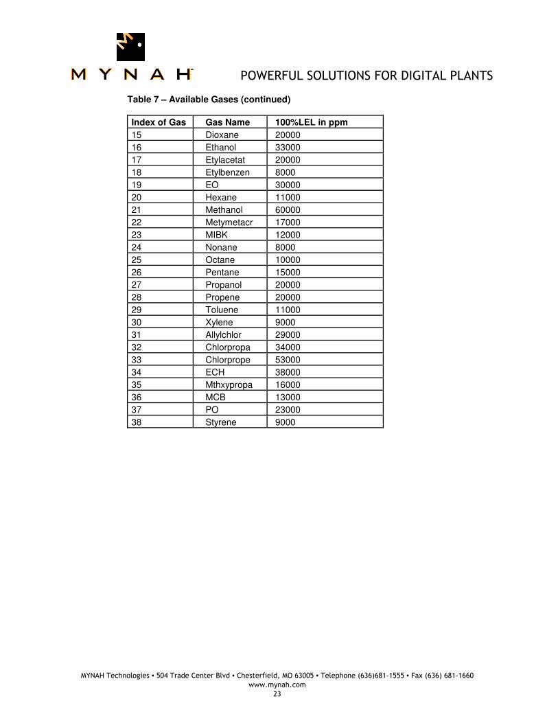
Here, the input parameters show the current readings. User will write a new gas index into the parameter SELECTION. The available gases are as follows. Any selection outside the range 1-38 is rejected by the driver. Given the gas index selection, the driver internally sends the 100% LEL in PPM value and %LEL units to the device. Table 7 – Available Gases
Index of Gas Gas Name 100%LEL in ppm
1 Methane 50000
2 Propane 21000
3 Ethene 27500
4 Acetone 25000
5 Benzene 12000
6 Butadiene 20000
7 Butane 16000
8 Butanol 14000
9 Butanone 14000
10 Butene 16500
11 Butylaceta 17000
12 Butylacryl 15000
13 Cyclpentan 11000

POWERFUL SOLUTIONS FOR DIGITAL PLANTS
MYNAH Technologies ▪ 504 Trade Center Blvd ▪ Chesterfield, MO 63005 ▪ Telephone (636)681-1555 ▪ Fax (636) 681-1660
www.mynah.com
22
14 Dimetyleth 27000
POWERFUL SOLUTIONS FOR DIGITAL PLANTS
MYNAH Technologies ▪ 504 Trade Center Blvd ▪ Chesterfield, MO 63005 ▪ Telephone (636)681-1555 ▪ Fax (636) 681-1660
www.mynah.com
23
Table 7 – Available Gases (continued)
Index of Gas Gas Name 100%LEL in ppm
15 Dioxane 20000
16 Ethanol 33000
17 Etylacetat 20000
18 Etylbenzen 8000
19 EO 30000
20 Hexane 11000
21 Methanol 60000
22 Metymetacr 17000
23 MIBK 12000
24 Nonane 8000
25 Octane 10000
26 Pentane 15000
27 Propanol 20000
28 Propene 20000
29 Toluene 11000
30 Xylene 9000
31 Allylchlor 29000
32 Chlorpropa 34000
33 Chlorprope 53000
34 ECH 38000
35 Mthxypropa 16000
36 MCB 13000
37 PO 23000
38 Styrene 9000
POWERFUL SOLUTIONS FOR DIGITAL PLANTS
MYNAH Technologies ▪ 504 Trade Center Blvd ▪ Chesterfield, MO 63005 ▪ Telephone (636)681-1555 ▪ Fax (636) 681-1660
www.mynah.com
24
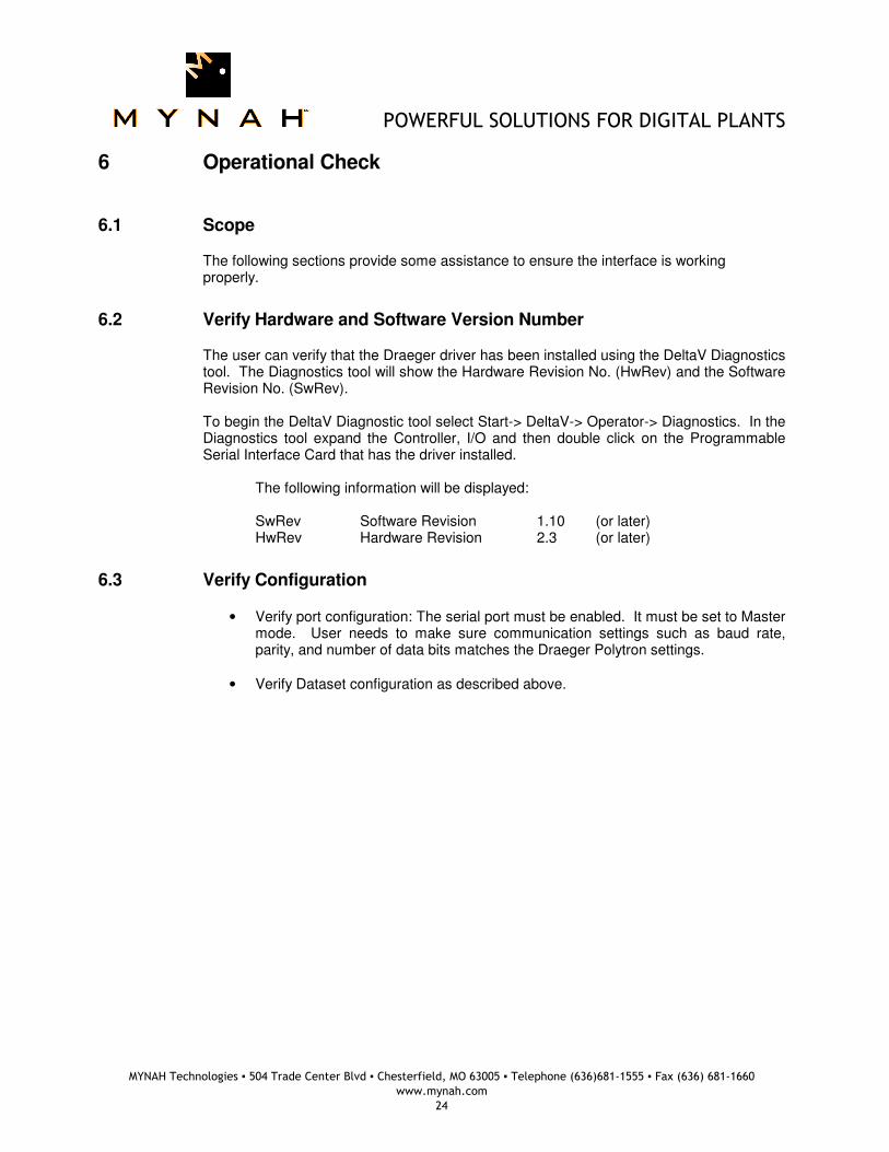
6 Operational Check
6.1 Scope
The following sections provide some assistance to ensure the interface is working properly.
6.2 Verify Hardware and Software Version Number
The user can verify that the Draeger driver has been installed using the DeltaV Diagnostics tool. The Diagnostics tool will show the Hardware Revision No. (HwRev) and the Software Revision No. (SwRev). To begin the DeltaV Diagnostic tool select Start-> DeltaV-> Operator-> Diagnostics. In the Diagnostics tool expand the Controller, I/O and then double click on the Programmable Serial Interface Card that has the driver installed.
The following information will be displayed: SwRev Software Revision 1.10 (or later) HwRev Hardware Revision 2.3 (or later)
6.3 Verify Configuration
• Verify port configuration: The serial port must be enabled. It must be set to Master mode. User needs to make sure communication settings such as baud rate, parity, and number of data bits matches the Draeger Polytron settings.
• Verify Dataset configuration as described above.

POWERFUL SOLUTIONS FOR DIGITAL PLANTS
MYNAH Technologies ▪ 504 Trade Center Blvd ▪ Chesterfield, MO 63005 ▪ Telephone (636)681-1555 ▪ Fax (636) 681-1660
www.mynah.com
25
6.4 Verify I/O Communication with Control Studio
• User can create I/O modules in the control studio to verify correct values are read and written between the foreign device and the PSIC. For input data, the values should be changed in the foreign device and verified that the new data are correctly reported.
• To assign a Dataset and a register in the Dataset to an I/O module, follow these steps:
1. Double click the IO_IN/IO_OUT parameter for the module. This brings up the IO_IN/IO_OUT Property window.
2. Click on the Browse button. This brings up the Browse window.
3. Click on the Object_Type drop down list, select All. This displays all the Dataset tags.
4. Double click on the desired Dataset tag. This assigns the tag to the module and closes the Browse window.
5. Choose the desired register in the Parameter drop down list.
6. Click the OK button.
6.5 Using Diagnostics
• Verify PSIC communication: Select the PSIC on Diagnostics and press the right mouse button. Select Display Real -Time Statistics from the drop down menu. If the Programmable Serial Interface Card is functioning then the user will see the Valid Responses counter and the Async and/or Sync Transactions counters incrementing. There will not be any error statistics counting up.
• Verify port statistics: Select the Port on the Programmable Serial Interface Card and press the right mouse button. Then select Display Port Statistics from the drop down menu. Verify that the port communications statistics are being displayed properly and are counting as expected for the protocol’s functionality.
• Verify dataset values: Select a dataset and press the right mouse button. Select View Dataset Registers from the Drop down window. Verify that the dataset values are displayed as expected.
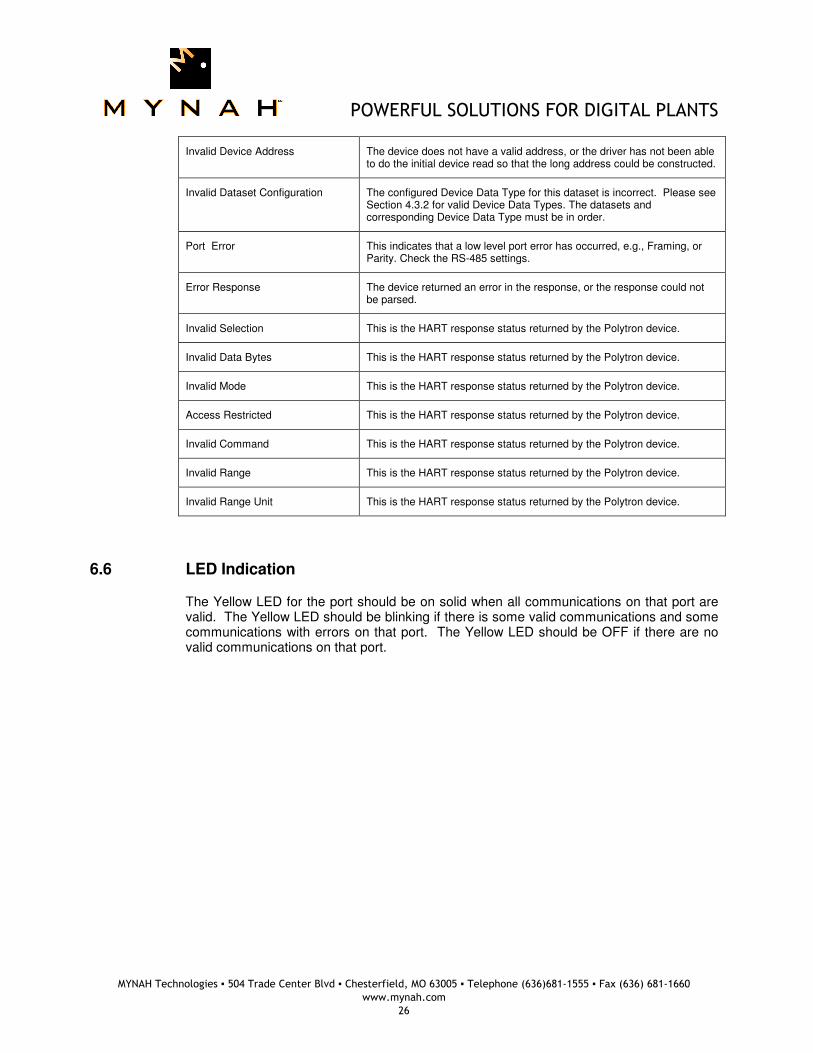
• Check the dataset status: Navigate down to the dataset in the left-pane and left-click on a dataset that has a bad status. The right-pane will display a Status parameter. Table 3 lists possible strings and common reasons for the error.
Table 3 - Dataset Status Strings
Status String Common Causes
No Response The serial card sent a message to the display, but did not receive a response. This could indicate a wiring issue or a miss-match of the port settings (baud rate, parity, data bits, stop bits)
CRC Error The serial card received a response, however the CRC in the message packet was incorrect. This could indicate a wiring issue or a miss-match of the port settings (baud rate, parity, data bits, stop bits)
POWERFUL SOLUTIONS FOR DIGITAL PLANTS
MYNAH Technologies ▪ 504 Trade Center Blvd ▪ Chesterfield, MO 63005 ▪ Telephone (636)681-1555 ▪ Fax (636) 681-1660
www.mynah.com
26
Invalid Device Address The device does not have a valid address, or the driver has not been able to do the initial device read so that the long address could be constructed.
Invalid Dataset Configuration The configured Device Data Type for this dataset is incorrect. Please see Section 4.3.2 for valid Device Data Types. The datasets and corresponding Device Data Type must be in order.
Port Error This indicates that a low level port error has occurred, e.g., Framing, or Parity. Check the RS-485 settings.
Error Response The device returned an error in the response, or the response could not be parsed.
Invalid Selection This is the HART response status returned by the Polytron device.
Invalid Data Bytes This is the HART response status returned by the Polytron device.
Invalid Mode This is the HART response status returned by the Polytron device.
Access Restricted This is the HART response status returned by the Polytron device.
Invalid Command This is the HART response status returned by the Polytron device.
Invalid Range This is the HART response status returned by the Polytron device.
Invalid Range Unit This is the HART response status returned by the Polytron device.
6.6 LED Indication
The Yellow LED for the port should be on solid when all communications on that port are valid. The Yellow LED should be blinking if there is some valid communications and some communications with errors on that port. The Yellow LED should be OFF if there are no valid communications on that port.
POWERFUL SOLUTIONS FOR DIGITAL PLANTS
MYNAH Technologies ▪ 504 Trade Center Blvd ▪ Chesterfield, MO 63005 ▪ Telephone (636)681-1555 ▪ Fax (636) 681-1660
www.mynah.com
27
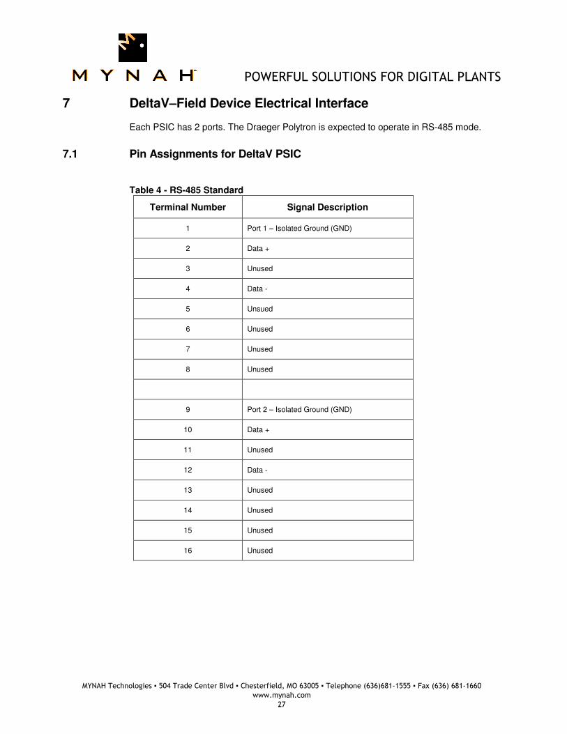
7 DeltaV–Field Device Electrical Interface
Each PSIC has 2 ports. The Draeger Polytron is expected to operate in RS-485 mode.
7.1 Pin Assignments for DeltaV PSIC
Table 4 - RS-485 Standard
Terminal Number Signal Description
1 Port 1 – Isolated Ground (GND)
2 Data +
3 Unused
4 Data -
5 Unsued
6 Unused
7 Unused
8 Unused
9 Port 2 – Isolated Ground (GND)
10 Data +
11 Unused
12 Data -
13 Unused
14 Unused
15 Unused
16 Unused

POWERFUL SOLUTIONS FOR DIGITAL PLANTS
MYNAH Technologies ▪ 504 Trade Center Blvd ▪ Chesterfield, MO 63005 ▪ Telephone (636)681-1555 ▪ Fax (636) 681-1660
www.mynah.com
28
Wiring Connections (RS-485) The figure below shows the connections between a Draeger Polytron device and Port 1 on the Serial Card Termination Block.

POWERFUL SOLUTIONS FOR DIGITAL PLANTS
MYNAH Technologies ▪ 504 Trade Center Blvd ▪ Chesterfield, MO 63005 ▪ Telephone (636)681-1555 ▪ Fax (636) 681-1660
www.mynah.com
29
8 Technical Support
For technical support or to report a defect, please give Mynah Technologies a call at (636) 681-1555. If a defect is discovered, please document it in as much detail as possible and then fax your report to us at (636) 681-1660. You can also send us your questions via e-mail. Our address is:
[email protected] Thank you for using DeltaV.