draft environmental impact assessment report ram eia report.pdf · draft environmental impact...
TRANSCRIPT
Draft Environmental Impact Assessment Report
M/s Shree Ram Electrocast Pvt Ltd., Page 1
DRAFT ENVIRONMENTAL IMPACT
ASSESSMENT REPORT
for
Expansion of existing
1,20,000 TPA Pig Iron unit to 2,00,000 TPA, 1,20,000 TPA Ductile
Iron pipe Plant to 2,00,000 TPA,
And 3.2 MW Captive Power Plant to 32.5 MW and
Establishment of
Coke Oven Plant - 1,60,000 TPA,
Sinter Plant– 3,00,000 TPA AND
Cement Grinding Plant – 1,00,000 TPA
atHonnarahalli , Halkote Village, Post-Hatcholi, Taluk Siruguppa, Dist.-Bellary,
Karnataka – 583114
By
M/s Shree Ram Electrocast
Pvt. Ltd.
ENVIRONMENTAL HEALTH & SAFETY
CONSULTANTS PRIVATE LTD,
# 13/2, 1ST MAIN ROAD, NEAR FIRE STATION,
INDUSTRIAL AREA, RAJAJINAGAR,
BANGALORE-560 010,
Tele: 080-23012100, Fax: 080 23012111
Email:[email protected]/[email protected]
www.ehsc.in
PRAGATHI LABS AND
CONSULTANTS PVT. LTD.
PLOT NO.8, TARBUND X ROAD,
SECUNDERABAD-9
Draft Environmental Impact Assessment Report
M/s Shree Ram Electrocast Pvt Ltd., Page 2
Table of ContentsCHAPTER I - INTRODUCTION ................................................................................................ 181.0 Company Profile ..................................................................................................................... 18
1.1 Project Details ......................................................................................................................... 191.2 Purpose of the Report.............................................................................................................. 19
1.3 Need of the project and its Importance in the Country........................................................... 201.4 Comparison of Existing and Proposed Plants ......................................................................... 211.5 Project location ....................................................................................................................... 22
1.6 Siting Criteria .......................................................................................................................... 251.7 List of Industries ..................................................................................................................... 27
1.8 Scope of the Work................................................................................................................... 271.9 Impact Assessment Methodologies......................................................................................... 28
1.9.1 Air Quality Modeling....................................................................................................... 28
1.10 Environment Management Plan............................................................................................ 281.10.1 Green Belt Development Plan ....................................................................................... 28
1.11 Disaster Management Plan and Occupational Safety........................................................... 291.12 Post Study Monitoring Plan.................................................................................................. 29CHAPTER II- PROJECT DESCRIPTION .................................................................................. 30
2.1 Introduction............................................................................................................................. 302.2 Location .................................................................................................................................. 30
2.3 Project Description with Process Details:............................................................................... 412.3.1 Modernisation of Pig Iron Plant....................................................................................... 412.3.2 Coke Oven Plant .............................................................................................................. 43
2.3.3 Power Plant ...................................................................................................................... 472.3.4 Ductile Iron Pipe Plant ..................................................................................................... 49
2.3.5 SINTER PLANT.............................................................................................................. 562.3.6 Cement Grinding Plant .................................................................................................... 60
2.4 WATER AND POWER REQUIREMENT............................................................................ 64
2.5 MANPOWER ......................................................................................................................... 68CHAPTER III- DESCRIPTION OF THE ENVIRONMENT...................................................... 69
3.0 Introduction............................................................................................................................. 693.1 Baseline Data .......................................................................................................................... 703.2 Soil Characteristics ................................................................................................................. 70
3.3 Air Environment ..................................................................................................................... 733.3.1 Micrometeorological Data ............................................................................................... 73
3.3.1.1 Historical Data .......................................................................................................... 733.3.1.2 Meteorology – Data generated at plant site .............................................................. 75
3.3.2 Selection of AAQ stations ............................................................................................... 77
3.3.3 Existing AAQ (Pre-project) status ................................................................................... 773.4 NOISE ENVIRONMENT ...................................................................................................... 86
3.4.1 Impact Assessment of Noise Environment ...................................................................... 863.4.2 Existing Noise Levels ...................................................................................................... 863.4.3 Methodology of Noise measurement ............................................................................... 88
3.5 WATER ENVIRONMENT.................................................................................................... 90
Draft Environmental Impact Assessment Report
M/s Shree Ram Electrocast Pvt Ltd., Page 3
3.5.1 Water quality monitoring ................................................................................................. 90
3.6 Hydrology ............................................................................................................................... 983.6.1 Hydrometeorology ........................................................................................................... 983.6.2 Rainfall............................................................................................................................. 98
3.7 Geology and Structures ........................................................................................................... 993.7.1 Regional Geology ............................................................................................................ 99
3.8 Hydrogeology.......................................................................................................................... 993.9 ECOLOGICAL STATUS (TERRESTRIAL AND AQUATIC).......................................... 1053.10 Demographic data ............................................................................................................... 108
CHAPTER-IV ANTICIPATED IMPACTS ............................................................................... 1094.0 Introduction........................................................................................................................... 109
4.1 ANTICIPATED ENVIRONMENTAL IMPACTS AND MITIGATION MEASURES ..... 1104.2 Impact on Environment during Construction Phase ............................................................. 120
4.2.1 Impact on Land use ........................................................................................................ 120
4.2.2 Impact on Soil ................................................................................................................ 1204.2.3 Impact on Air Quality .................................................................................................... 121
4.2.4 Impact on Water Quality................................................................................................ 1214.2.5 Impact on Noise Levels .................................................................................................. 1214.2.6 Impact on Terrestrial Ecology........................................................................................ 123
4.2.7 Impact on Aquatic Ecology............................................................................................ 1234.2.8 Demography and Socio-economics ............................................................................... 123
4.2.9 Public Expectation ......................................................................................................... 1244.3 Identification of Potential Impacts during Operational Phase .............................................. 124
4.3.1 Impact on Soil ................................................................................................................ 125
4.3.2 Topography and Climate................................................................................................ 1254.3.2.1 Impact on Topography............................................................................................ 125
4.3.2.2 Impact on Climate ................................................................................................... 1254.3.3 Impact on Air Quality .................................................................................................... 125
4.3.3.1 Air Pollution Impact Identification by use of Air Modeling .................................. 126
4.3.3.2 Pollutants/Model Options Considered For Computations ...................................... 1264.3.3.3 Model Input Data .................................................................................................... 127
4.3.3.4 Fugitive Emissions .................................................................................................. 1274.3.4 Impact on Traffic ........................................................................................................... 1304.3.5 Impact on Water Resources ........................................................................................... 134
4.3.6 Impact on Water Quality................................................................................................ 1344.3.7 Impact of solid waste ..................................................................................................... 134
4.3.8 Impact on Noise Levels .................................................................................................. 1354.3.9 Impact on Ecology ......................................................................................................... 1354.3.10 Socio-Economics ......................................................................................................... 136
CHAPTER V-ENVIRONMENTAL MONITORING PROGRAMME..................................... 1375.1 Environmental Monitoring.................................................................................................... 137
5.2 Environmental Monitoring Plan ........................................................................................... 138CHAPTER-VI............................................................................................................................. 140OCCUPATIONAL HEALTH AND SAFETY AND DISASTER MANAGEMENT PLAN.... 140
6.0 Introduction........................................................................................................................... 1406.1 Quality, Environment and Occupational Health and Safety Policy...................................... 140
6.2 HAZARD CHART ............................................................................................................... 142

Draft Environmental Impact Assessment Report
M/s Shree Ram Electrocast Pvt Ltd., Page 4
6.3 Occupational Health.............................................................................................................. 148
6.4 Safety Plan ............................................................................................................................ 1496.4.1 General........................................................................................................................... 1496.4.2 House – keeping............................................................................................................. 150
6.4.3 Wearing apparel............................................................................................................. 1506.4.4 Protective equipment ...................................................................................................... 150
6.4.5 Stacking of materials...................................................................................................... 1506.4.6 Loading of material........................................................................................................ 1506.4.7 Eye protection................................................................................................................ 150
6.4.8 Safety belts ..................................................................................................................... 1516.4.9 Transport ........................................................................................................................ 151
6.4.10 Short cuts...................................................................................................................... 1516.4.11 Defective tools ............................................................................................................. 1516.4.12 Power rails or transmission line ................................................................................... 151
6.4.13 Guards .......................................................................................................................... 1516.4.14 Refueling ...................................................................................................................... 151
6.4.15 Permit to work.............................................................................................................. 1526.4.16 Starting and repairing machinery................................................................................. 1526.4.17 Lifting or carrying weights .......................................................................................... 152
6.4.18 Overhead crane ............................................................................................................ 1536.4.19 Electricity..................................................................................................................... 154
6.4.20 Ladders and scaffolds................................................................................................... 1546.4.21 Working overhead........................................................................................................ 1556.4.23 Welding and gas cutting............................................................................................... 155
6.4.24 Hot metal and slag........................................................................................................ 1556.4.25 Fire in coal yard ........................................................................................................... 156
6.4.26 Open manholes............................................................................................................. 1566.4.27 Excavations .................................................................................................................. 1566.4.28 Vehicles........................................................................................................................ 157
6.4.29 First aid boxes .............................................................................................................. 1576.4.30 Fire fighting equipment ................................................................................................ 157
6.4.31 Unfamiliar equipment .................................................................................................. 1586.4.32 Horseplay..................................................................................................................... 1586.4.33 Work permits................................................................................................................ 158
6.5 Administrative Controls ........................................................................................................ 1586.6 Personal Protective Equipment (PPE) .................................................................................. 159
6.7 Emergency Organization....................................................................................................... 1606.8 ROLES AND RESPONSIBILITIES OF EMERGENCY ORGANISATION..................... 161
6.8.1 Site Controller................................................................................................................ 161
6.8.2 Incident Controller ......................................................................................................... 1626.8.3 Emergency Coordinator (Services & communication) .................................................. 162
6.8.4 Emergency Coordinator (First Aid & Medical Management)....................................... 1636.8.5 Emergency Coordinate (Security & Supply) ................................................................. 1636.8.6 Emergency Coordinator (Production Unit).................................................................... 164
6.8.7 Emergency Coordinator (Utility & Maintenance) ......................................................... 1646.8.8 Assistant – Communication........................................................................................... 164
6.8.9 Safety squad ................................................................................................................... 165
Draft Environmental Impact Assessment Report
M/s Shree Ram Electrocast Pvt Ltd., Page 5
6.8.10 Drive – Ambulance ...................................................................................................... 165
6.8.11 In Charge – Occupational Health Center ..................................................................... 1656.8.12 Department heads / shift / in charge / supervisors ....................................................... 1666.8.13 Duties of Receptionist / Telephone Operator............................................................... 166
6.9 Emergency Response Plan.................................................................................................... 1676.10 Health register will be maintained as follows:.................................................................... 167
6.11 Emergency Action Plans ..................................................................................................... 1686.11.1 Emergency Action Plan for Cylinder Fire: .................................................................. 1686.11.2 Emergency Action Plan for Electric Fire:.................................................................... 169
6.11.3 Emergency Action Plan for Office Fire:...................................................................... 1696.11.4 Emergency Action Plan for Oil Fire:........................................................................... 169
6.11.5 Emergency Action Plan for Medical Aid: ................................................................... 1706.12 Natural Hazards................................................................................................................... 171
6.12.1 Emergency Action Plan for Tornado/High Winds: ..................................................... 171
6.12.2 Emergency Action Plan for Earthquakes..................................................................... 1726.12.3 Emergency Action Plan for Bomb Threat ................................................................... 172
6.13 GUIDELINES FOR SHUTDOWN OF PRODUCTION BLOCKS .................................. 1736.14 EMERGENCY PLANNING .............................................................................................. 174
6.14.1 TRAINING AND REHEARSAL ................................................................................ 174
6.14.2 ACTION PLAN / TRANING...................................................................................... 1756.14.3 GENERAL SAFETY................................................................................................... 175
6.14.5 SAFETY WHILE HANDLING EQUIPMENT .......................................................... 1766.14.5 ELECTRICAL SAFETY ............................................................................................. 1776.14.6 FIRE SAFETY............................................................................................................. 178
6.14.6.1 FIRE...................................................................................................................... 1786.14.6.2 FIRE FIGHTING, RESCUE AND FIRST AID TEAM....................................... 179
6.15 DECLARATION OF EMERGENCY ................................................................................ 1806.16 EMERGENCY SIREN ....................................................................................................... 1806.17 EVACUATION OF PERSONNEL .................................................................................... 181
6.18 SAFE ASSEMBLY POINTS ............................................................................................. 1816.19 ACCOUNTING OF PERSONNEL.................................................................................... 181
6.20 ARRANGEMENT FOR MEDICAL TREATMENT......................................................... 1816.21 INFORMATION TO RELATIVES OF INJURED............................................................ 1826.22 INFORMATION TO LOCAL AUTHORITIES ................................................................ 182
6.23 INFORMATION TO DISTRICT AUTHORITIES ............................................................ 1826.24 LAW & ORDER................................................................................................................. 183
6.25 ALL CLEAR SIGNAL ....................................................................................................... 1836.26 Occupational Health Surveillance Programme ................................................................... 184CHAPTER-VII............................................................................................................................ 188
PROJECT BENEFITS ................................................................................................................ 1887.1. PHYSICAL INFRASTRUCTURE...................................................................................... 188
7.2. SOCIAL INFRASTRUCTURE........................................................................................... 1887.3. EMPLOYMENT POTENTIAL........................................................................................... 188
7.3.1. SKILLED...................................................................................................................... 188
7.3.2. SEMI- SKILLED .......................................................................................................... 1887.3.3. UNSKILLED ................................................................................................................ 188
7.4. OTHER BENEFITS............................................................................................................. 188
Draft Environmental Impact Assessment Report
M/s Shree Ram Electrocast Pvt Ltd., Page 6
7.5 SOCIO-ECONOMIC DEVELOPMENTAL ACTIVITIES ................................................. 189
CHAPTER-VIII .......................................................................................................................... 192ENVIRONMENTAL MANAGEMENT PLAN......................................................................... 1928.1 Introduction........................................................................................................................... 192
8.2 Environmental Management during Construction Stage ...................................................... 1928.2.1 Water Resources and Quality......................................................................................... 194
8.2.2 Air Quality ..................................................................................................................... 1958.2.3 Noise Level .................................................................................................................... 1958.2.4 Solid /Hazardous Waste Management ........................................................................... 196
8.2.5 Site Security................................................................................................................... 1968.2.6 Traffic Pattern................................................................................................................ 196
8.2.7 Solid Waste Generation ................................................................................................. 1978.2.8 Ecological Aspects ......................................................................................................... 1978.2.9 Aesthetics....................................................................................................................... 197
8.2.10 Socio-Economic........................................................................................................ 1978.3 Operation stage ..................................................................................................................... 198
8.3.1 Air Environment ............................................................................................................ 1988.3.1.1 Air Pollution Control Equipment ............................................................................ 1998.3.1.2 For Fugitive Dust control........................................................................................ 202
8.3.2 Water Pollution.............................................................................................................. 2048.3.2.1 Water Environment ................................................................................................. 204
8.3.2.2 Water Pollution Control and Conservation............................................................. 2048.3.2.3 Water pollution control........................................................................................... 204
8.3.3 Noise Pollution............................................................................................................... 205
8.3.3.1 Noise Environment: ................................................................................................ 2058.3.4 Solid Waste .................................................................................................................... 206
8.3.5 Greenbelt Development ................................................................................................. 2068.3.5.1 Action plan for development of Greenbelt in 35% area ......................................... 207
8.3.6 Storm Water Management ............................................................................................. 208
8.3.7 Ecological Aspects ......................................................................................................... 2108.3.8 Aesthetics Aspects ......................................................................................................... 210
8.3.9 Socio Economic Aspects................................................................................................ 2108.3.10 Land Management ........................................................................................................ 2118.3.11 Traffic Management Plan............................................................................................. 211
8.4 Existing Environmental Management plan........................................................................... 2138.4.1 Wastewater..................................................................................................................... 213
8.4.2 Air Environment ............................................................................................................ 2138.4.3 Stack Emissions ............................................................................................................. 2138.4.4 Fugitive Emission .......................................................................................................... 214
8.4.5 Noise Environment ........................................................................................................ 2148.4.6 Land Management .......................................................................................................... 215
8.4.7 Green Belt Development ................................................................................................ 2158.5 Conservation of Air, Water and Energy recovery................................................................. 2188.6 Budgetary allocation for Environmental Protection Measures (in Rs. Lakhs) ..................... 219
8.7 CREP GUIDELINES ............................................................................................................ 220CHAPTER-IX SUMMARY AND CONCLUSION................................................................... 223
CHAPTER-1 INTRODUCTION............................................................................................ 223

Draft Environmental Impact Assessment Report
M/s Shree Ram Electrocast Pvt Ltd., Page 7
CHAPTER-2 PROJECT DESCRIPTION .............................................................................. 226
CHAPTER-3.0 BASELINE ENVIRONMENTAL SCENARIO ........................................... 227CHAPTER-4.0 ANTICIPATED IMPACT AND MITIGATION MEASURES ................... 229CHAPTER-5.0 ENVIRONMENTAL MONITORING PLAN .............................................. 237
CHAPTER-6.0 RISK ASSESSMENT AND DISASTER MANAGEMENT PLAN ............ 238CHAPTER-7.0 PROJECT BENEFITS .................................................................................. 242
CHAPTER-8.0 ENVIRONMENTAL MANAGEMENT PLAN ........................................... 244CHAPTER-X .............................................................................................................................. 250DISCLOSURE OF CONSULTANTS ENGAGED WITH RESPECT THE PROJECT ........... 250
List of TablesTable 1.1 Existing Manufacturing Facilities................................................................................. 18Table 1.2 Production details.......................................................................................................... 18
Table 1.3: Envisaged project capacities ........................................................................................ 19Table 1.4 Existing and Expansion Features .................................................................................. 21
Table 1.5 Proposed Project Details ............................................................................................... 23Table 1.6 Environmental settings around the proposed project site (Within 10 kms radius)....... 24Table 1.7 Siting Criteria................................................................................................................ 25
Table 1.8 List of Industries ........................................................................................................... 27Table 1.9 Scope of work ............................................................................................................... 27
Table 2.1: Land Breakup of the Existing and Proposed Expansion ............................................. 31Table 2.2: Summary of Development- phase wise ....................................................................... 40Table: 2.3 Raw material Requirement .......................................................................................... 41
Table 2.4 Chemical characteristics of Iron ore ............................................................................. 42Table 2.5 Chemical characteristics of Limestone ......................................................................... 42Table 2.6 Chemical characteristics of Dolomite ........................................................................... 42
Table 2.7 Chemical characteristics of Quartz............................................................................... 43Table 2.8: Material balance........................................................................................................... 43
Table 2.9 BF gas generation and utilization ................................................................................. 43Table 2.10 Raw materials required ............................................................................................... 46Table 2.11: Quality of Coal........................................................................................................... 46
Table 2.12 Material balance – Coke Oven plant ........................................................................... 47Table 2.13 Raw material requirement........................................................................................... 48
Table 2.14 Chemical characteristics of coal ................................................................................. 48Table 2.15 Raw materials required ............................................................................................... 53Table 2.16 Chemical analysis of Ferrosilicon............................................................................... 53
Table 2.17 Chemical analysis of Silico manganese ...................................................................... 54Table 2.18 Material Balance- Ductile Iron Pipe plant .................................................................. 54
Table 2.19 Design parameters of sinter plant ............................................................................... 56Table 2.20 Raw materials requirement ........................................................................................... 1Table 2.21 Material Balance- Sinter plant .................................................................................... 60
Table 2.22 Raw material requirement........................................................................................... 60Table 2.23 Chemical analysis of Clinker...................................................................................... 61
Table 2.24 Chemical analysis of Gypsum .................................................................................... 61Table 2.25 Chemical analysis of BF slag...................................................................................... 61Table 2.26 Material Balance for Cement grinding plant .............................................................. 62

Draft Environmental Impact Assessment Report
M/s Shree Ram Electrocast Pvt Ltd., Page 8
Table 2.27 Makeup Water requirement ........................................................................................ 64
Table 2.28 Power Requirement ..................................................................................................... 66Table 2.29 Man power requirements ............................................................................................ 68Table 3.1 Primary data collected................................................................................................... 70
Table 3.2 Location of soil sampling stations ................................................................................ 71Table 3.3 Soil Quality Analysis .................................................................................................... 72
Table 3.4 Data collection for Meteorological data ....................................................................... 73Table 3.5 Meteorological Data (3 years) for Bellary.................................................................... 74Table 3.6 meterological data for the period Oct-Dec 2011........................................................... 76
Table 3.7 Air parameters analysed................................................................................................ 77Table: 3.8 Details of Air Quality monitoring station.................................................................... 80
Table: 3.9 Air quality monitoring results...................................................................................... 81Table 3.10 Concentration of PM10............................................................................................... 82Table 3.11 Concentration of PM2.5.............................................................................................. 82
Table 3.12 Concentration of SO2 ................................................................................................. 82Table 3.13 Concentration of NO2................................................................................................. 83
Table 3.14 Concentration of Lead................................................................................................. 83Table 3.15 Concentration of Ammonia ........................................................................................ 84Table 3.16 Concentration of CO................................................................................................... 85
Table 3.17 Concentration of Ozone .............................................................................................. 85Table 3.18 Noise locations............................................................................................................ 88
Table 3.19 Summary of Ambient Noise Level Monitoring Results ............................................. 90Table 3.20: water sampling station details .................................................................................... 92Table 3.21: Water Quality Results ................................................................................................ 93
Table 3.22 Monthly Annual Rainfall Distributions ...................................................................... 99Table 3.23 Flora found in the study area .................................................................................... 105
Table 3.24 List of major crops.................................................................................................... 106Table 3.25 List of fauna found in the study area ........................................................................ 107Table 3.27 List of aqua fauna ...................................................................................................... 107
Table 4.1 IMPACT IDENTIFICATION MATRIX.................................................................... 110Table 4.2 CHARACTERISTICS OF ENVIRONMENTAL IMPACTS FROM
CONSTRUCTION ACTIVITIES ............................................................................................... 113Table 4.3: CHARACTERISTICS OF ENVIRONMENTAL IMPACTS FROM OPERATIONAL PHASE........................................................................................................................................ 117
Table 4.4 Typical Noise Levels of Construction Equipment...................................................... 122Table 4.5 List of Pollution ways in stacks .................................................................................. 126
Table 4.6 Fugitive emission data .................................................................................................. 128Table 4.7 Summary of Air quality dispersion model: ................................................................... 129Table 4.8 Existing traffic ............................................................................................................ 131
Table 4.9 Generated Traffic Due to the Proposed expansion Project (Operation Phase) ........... 132Table 4.10 Solid waste generated from different operations (after expansion) .......................... 135
Table 5.1 Monitoring schedule for Environmental Parameter during construction phase ......... 137Table 5.2: Monitoring Schedule for Environmental Parameters ................................................ 137Table 5.3 Fugitive emission monitoring ..................................................................................... 139
Table 6.1 Identified Hazards ....................................................................................................... 143Table 6.2 Identified Occupational Health Hazards ..................................................................... 143
Table 6.3 Preliminary Hazard Analysis for Process and Storage Areas ..................................... 144

Draft Environmental Impact Assessment Report
M/s Shree Ram Electrocast Pvt Ltd., Page 9
Table 6.4 List of fire extinguishers ............................................................................................. 158
Table 6.5 Emergency Organisation............................................................................................. 160Table 6.6: Health Register............................................................................................................ 168Table: 7.1 CSR Activities conducted and proposed around factory premises ............................... 189
Table 8.1: EMP for Construction Phase Impacts "Site Clearing".............................................. 193Table 8.2: EMP for Construction Phase Impacts
"Transportation of Construction Materials”................................................................................ 193Table 8.3: EMP for Construction Phase Impacts "Construction Activities”.............................. 194Table 8.4: Characteristics of Secondary Fugitive Emissions ........................................................ 202
Table 8.5 Action plan to control fugitive dust .............................................................................. 203Table 8.6 Solid waste generated from different operations after expansion............................... 206
Table 8.7 Trucks details .............................................................................................................. 211Table 8.8 Capital Cost................................................................................................................. 219Table 8.9 Recurring Cost ............................................................................................................. 219
Table 8.10 Compliance to CREP guidelines............................................................................... 220
List of Figures
Fig: 1.1 Toposheet of the area showing the location of the industry with 15 kms radius
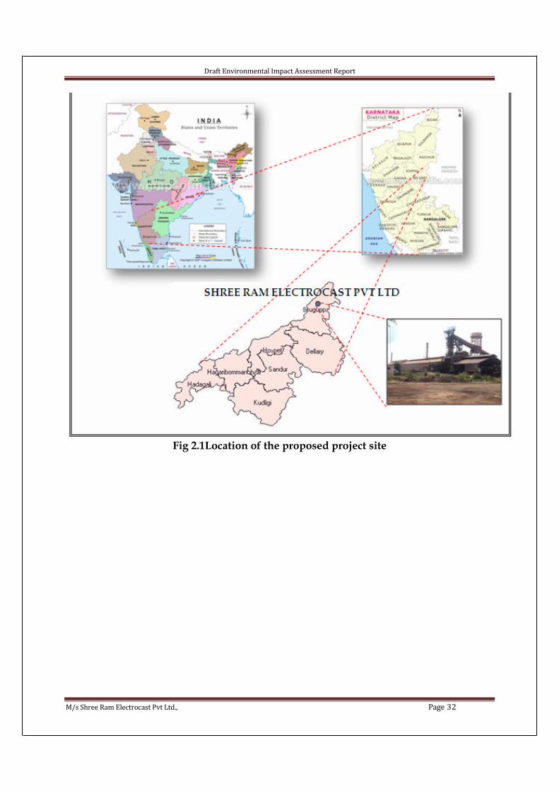
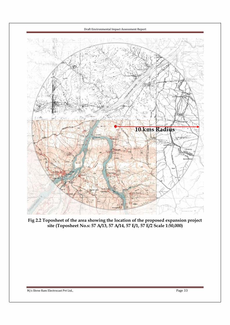
demarcation. .................................................................................................................................. 26Fig 2.1Location of the proposed project site ................................................................................ 32Fig 2.2 Toposheet of the area showing the location of the proposed expansion project site
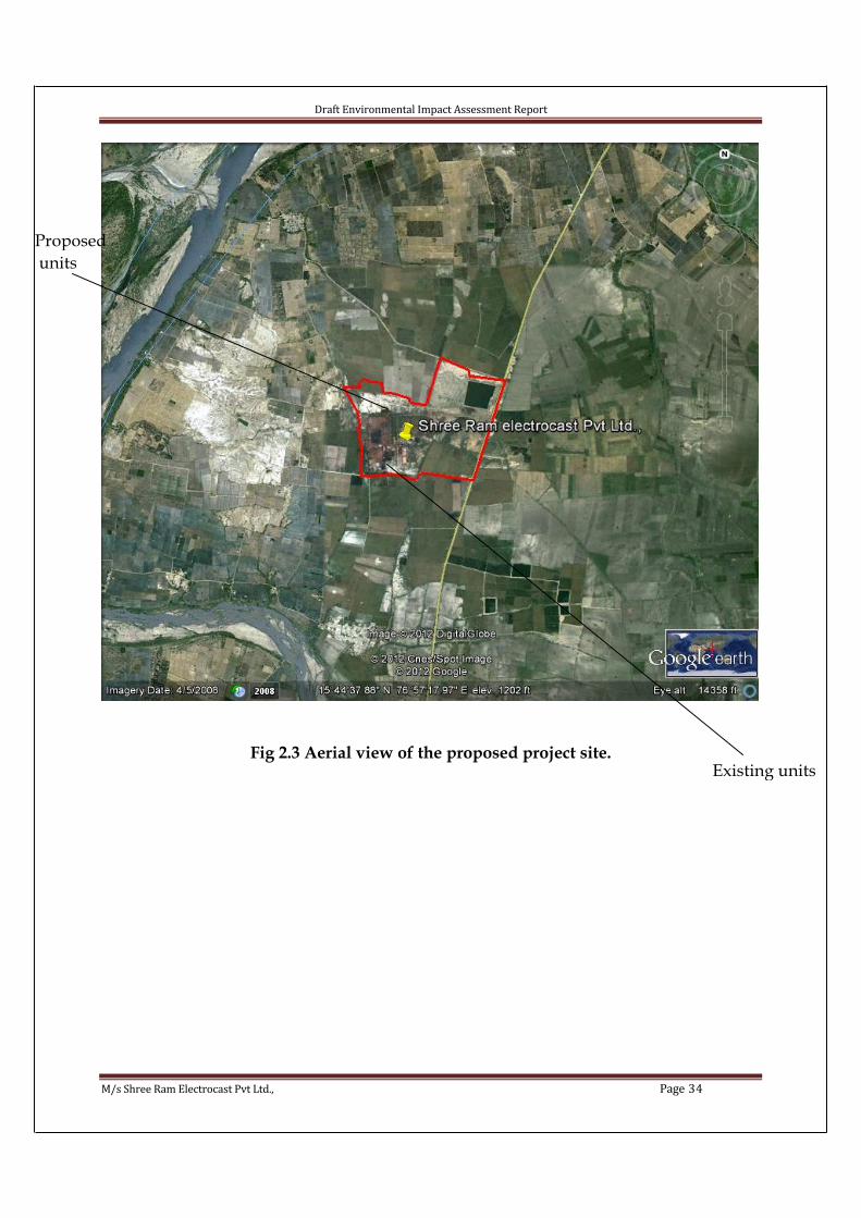
(Toposheet No.s: 57 A/13, 57 A/14, 57 E/1, 57 E/2 Scale 1:50,000) ........................................... 33Fig 2.3 Aerial view of the proposed project site. .......................................................................... 34
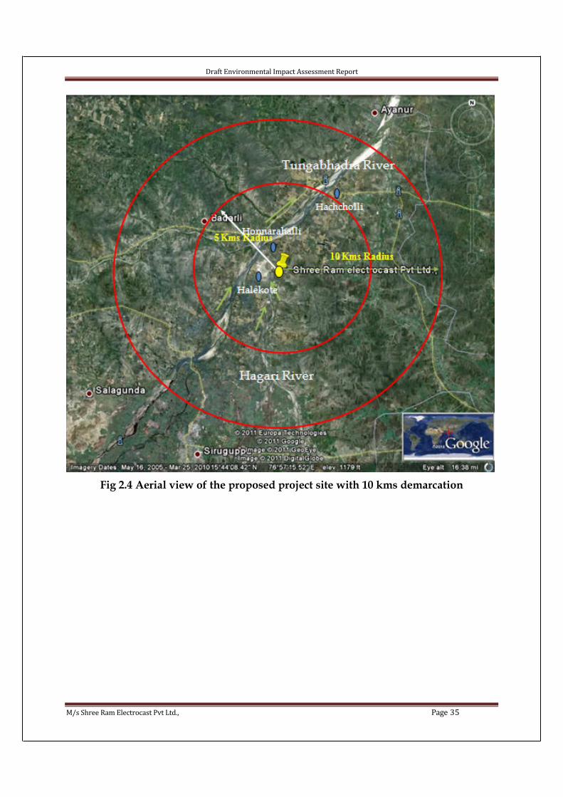
Fig 2.4 Aerial view of the proposed project site with 10 kms demarcation ................................. 35Fig 2.5 Satellite imagery of the study area ................................................................................... 36Fig 2.6 Photos showing the existing Pig Iron Unit ....................................................................... 37
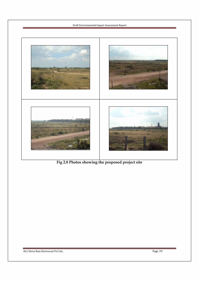
Fig 2.7 Photos showing site surrounding photograph................................................................... 38Fig 2.8 Photos showing the proposed project site......................................................................... 39
Fig 2.9 Flow chart of heat recovery stamping coke oven............................................................. 45Fig 2.10 Power Plant- Flow diagram ............................................................................................ 49Fig 2.12 Typical sinter plant ......................................................................................................... 57
Fig 2.13 Flow chart of sinter plant .................................................................................................. 1Fig 2.14 Mass Balance for the whole plant ................................................................................... 63
Fig 2.15 Water Balance chart........................................................................................................ 65Fig 2.16 Energy Balance chart ...................................................................................................... 67Fig 3.1 Location of Soil sampling stations ................................................................................... 71
Fig 3.2 Monitoring photographs ................................................................................................... 72Fig. 3.3 Meteorological Scenario – Wind Rose diagram.............................................................. 75
Fig. 3.4 Meteorological Scenario – Wind Rose diagram for Oct-Dec 2011................................. 77Fig 3.5 Air quality monitoring stations ......................................................................................... 79Fig : 3.6 Some of the Monitoring photographs ............................................................................. 80
Fig. 3.7 Map Showing Noise Sampling Locations ....................................................................... 87Fig 3.8 Noise monitoring photographs ......................................................................................... 89
Fig 3.9 Water monitoring stations ................................................................................................ 91

Draft Environmental Impact Assessment Report
M/s Shree Ram Electrocast Pvt Ltd., Page 10
Fig 3.10 Photographs of monitoring ............................................................................................. 92
Fig 4.1 Dispersion of particulate matter ..................................................................................... 128Fig 4.2 Dispersion of SO2 ........................................................................................................... 128Fig 4.3 Dispersion of NO2 .......................................................................................................... 129
Fig 6.1 Hazard Chart ................................................................................................................... 142Fig 6.2 Emergency Response Plan.............................................................................................. 167
Fig: 7.1 CSR activates carried out .............................................................................................. 191FIG 8.1 EXISITNG GREENBELT PHOTOGRAPHS ........................................................ 217
Annexures
1. 3 months AAQ data
2. Demographic details
3. Emission data
4. Modeling results
5. greenbelt development drawing and species list
TORs awarded
Draft Environmental Impact Assessment Report
M/s Shree Ram Electrocast Pvt Ltd., Page 11

Draft Environmental Impact Assessment Report
M/s Shree Ram Electrocast Pvt Ltd., Page 12
Draft Environmental Impact Assessment Report
M/s Shree Ram Electrocast Pvt Ltd., Page 13
Draft Environmental Impact Assessment Report
M/s Shree Ram Electrocast Pvt Ltd., Page 14
Draft Environmental Impact Assessment Report
M/s Shree Ram Electrocast Pvt Ltd., Page 15
Draft Environmental Impact Assessment Report
M/s Shree Ram Electrocast Pvt Ltd., Page 16

Draft Environmental Impact Assessment Report
M/s Shree Ram Electrocast Pvt Ltd., Page 17
TEAM MEMBERS
ENVIRONMENTAL CONSULTANCY SERVICES
1 Dr. M. Ravi Kiran (M.Sc, Ph.D), M/s Pragathi Labs and Consultants Pvt Ltd.,
2 Mr. Ch. Vishnu (B.Tech. Chemical), M/s Pragathi Labs and Consultants Pvt Ltd.,
3 Miss. Shaheda Begum (M.Sc Chemistry), M/s Pragathi Labs and Consultants Pvt Ltd.,
4 Miss. Y. Latha (M.Sc Chemistry), M/s Pragathi Labs and Consultants Pvt Ltd.,
5 Mr. Shivanand M Dambal, Managing Director, EHSCPL
6 Mr. Madhu Kumar, Technical Director, EHSCPL
7 Mrs. Praveena Kumari, Senior Environmental Engineer, EHSCPL
8 Ms. Bhavani, Environmental Engineer, EHSCPL
PROJECT CONSULTANTS
9 Mr. George Thomas
GIS CONSULTANT
10 Mr. Ananatha Rama
LAB SERVICES
11 M/s SGS India Pvt Ltd
12 M/s EHSRDC
AIR QUALITY MODELING AND PREDICTION
13 Mrs. Praveena Kumari
TOPOSHEETS
14 Survey of India

Draft Environmental Impact Assessment Report
M/s Shree Ram Electrocast Pvt Ltd., Page 18
CHAPTER I - INTRODUCTION1.0 Company Profile
Shree Ram Electro Cast Pvt. Ltd., was incorporated on 12th August, 2004 havingregistered office 8 Camac Street Shanti Niketan Building 9th Floor Room No. 8 Kolkata-17, West Bengal. Directors of the company are Mr Mukesh Bhandari, Mr. ShaileshBhandari, Mr. Avinash Bhandari and Mr R K Purohit.
Table 1.1 Existing Manufacturing Facilities
Unit Capacity Location
Pig Iron Plant
Captive Power Plant
120,000 TPA
2.5MW
Honarhalli, Hatcholi Post, Sirguppa Talluk, BellaryDistrict, Karnataka
The above unit was earlier owned by M/s Unimetal Ispat Limited and taken over by the company from Debt Recovery Tribunal, Bangalore, through public auction in Nov, 2004, at total consideration of Rs.15.40 Crores. Further, plant was upgraded under the guidance of MECON Limited, Bangalore with an expenditure of 12.00 Crores. As such, company invested total amount of Rs. 27.40 Crores on the plant and started thecommercial production from July, 2005. After the start of commercial operation, the plant was leased out to Kalyani Steels Limited, Pune (A Flagship company of Bharat Forge Limited).
The State Bank of India got the property valued by its empanelled valuer M/s Niketan Consultancy at Rs. 58.14 Crores in the year 2007-08.
The plant has an installed capacity of 120,000 TPA. The plant was again operated by SREPL from 12-07-2009 and achieved the following productions:
Table 1.2 Production details
Year Production (TPA)
2008-09 31893*
2009-10 48,230* Production is for five months only.
Directors
• Mr. Mukesh Bhandari is a businessman, having experience over 30years. He is a graduate in Electrical Engineering and is director invarious Companies. He is the Chairman of the flagship companyElectrotherm (I) Ltd
• Mr.Shailesh Bhandari is a businessman, having experience over 25years. He is a graduate and is director in various Companies. He is the
Draft Environmental Impact Assessment Report
M/s Shree Ram Electrocast Pvt Ltd., Page 19
Managing Director of the flagship company Electrotherm (I) Ltd
• Avinash Bhandari is a graduate in Engineering and has taken M.S and MBA from USA. He is having experience over 17 years and is director in various companies.
• Mr R K Purohit is an Engineering Graduate from Jadavpur University and has got over 30 yrs of experience in steel industry.
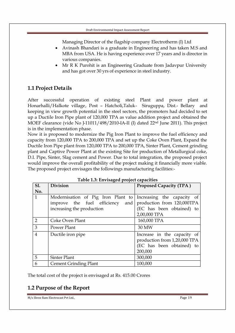
1.1 Project Details
After successful operation of existing steel Plant and power plant atHonarhalli/Halkote village, Post – Hatcholi,Taluk- Siruguppa, Dist.- Bellary andkeeping in view growth potential in the steel sectors, the promoters had decided to set up a Ductile Iron Pipe plant of 120,000 TPA as value addition project and obtained the MOEF clearance (vide No J-11011/498/2010-IA-II (I) dated 22nd June 2011). This project is in the implementation phase.Now it is proposed to modernize the Pig Iron Plant to improve the fuel efficiency and capacity from 120,000 TPA to 200,000 TPA and set up the Coke Oven Plant, Expand the Ductile Iron Pipe plant from 120,000 TPA to 200,000 TPA, Sinter Plant, Cement grinding plant and Captive Power Plant at the existing Site for production of Metallurgical coke, D.I. Pipe, Sinter, Slag cement and Power. Due to total integration, the proposed project would improve the overall profitability of the project making it financially more viable. The proposed project envisages the followings manufacturing facilities:-
Table 1.3: Envisaged project capacities
Sl.
No.
Division Proposed Capacity (TPA )
1 Modernisation of Pig Iron Plant toimprove the fuel efficiency andincreasing the production
Increasing the capacity ofproduction from 120,000TPA(EC has been obtained) to2,00,000 TPA
2 Coke Oven Plant 160,000 TPA
3 Power Plant 30 MW
4 Ductile iron pipe Increase in the capacity ofproduction from 1,20,000 TPA (EC has been obtained) to200,000
5 Sinter Plant 300,000
6 Cement Grinding Plant 100,000
The total cost of the project is envisaged at Rs. 415.00 Crores
1.2 Purpose of the Report

Draft Environmental Impact Assessment Report
M/s Shree Ram Electrocast Pvt Ltd., Page 20
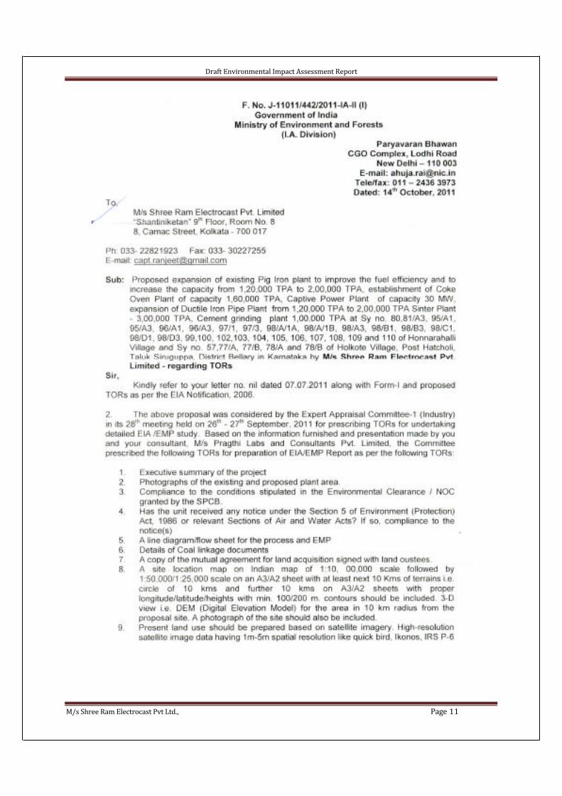
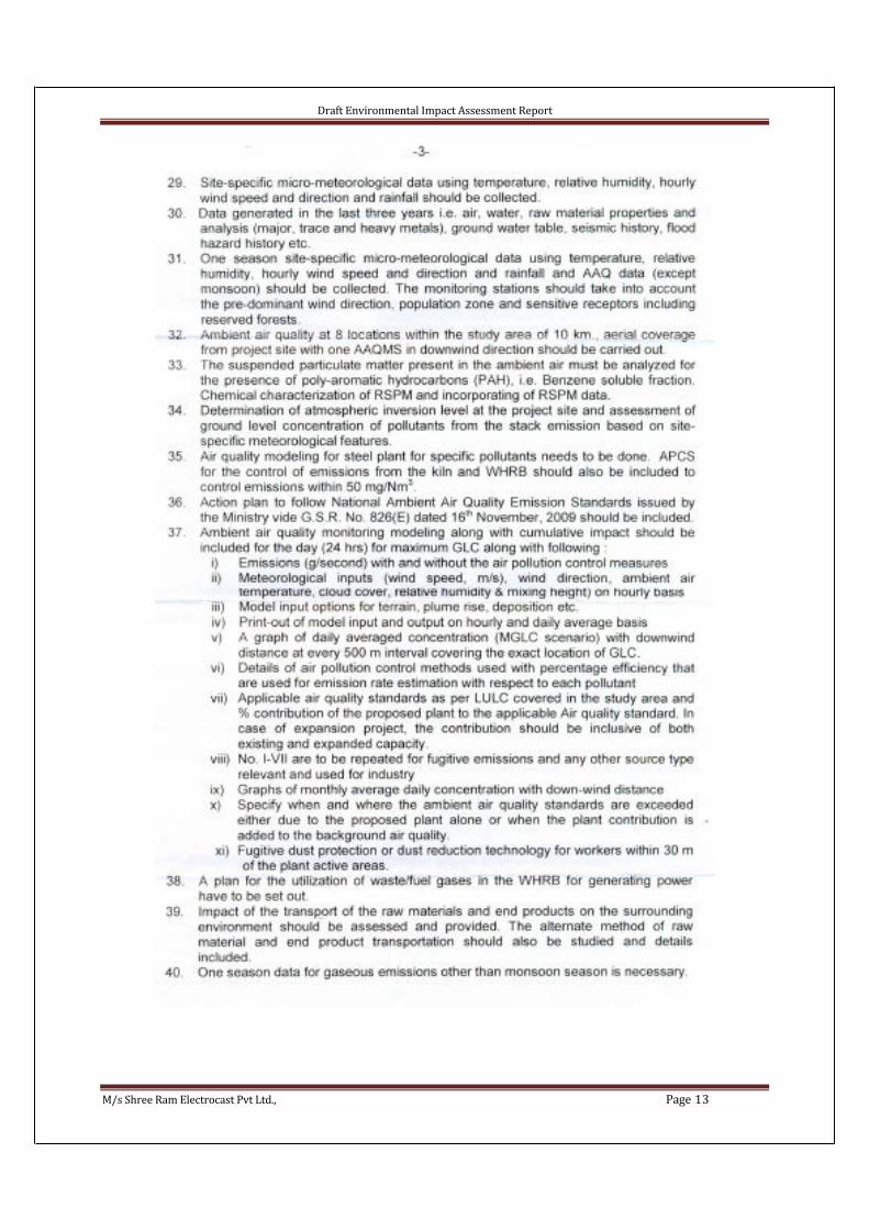
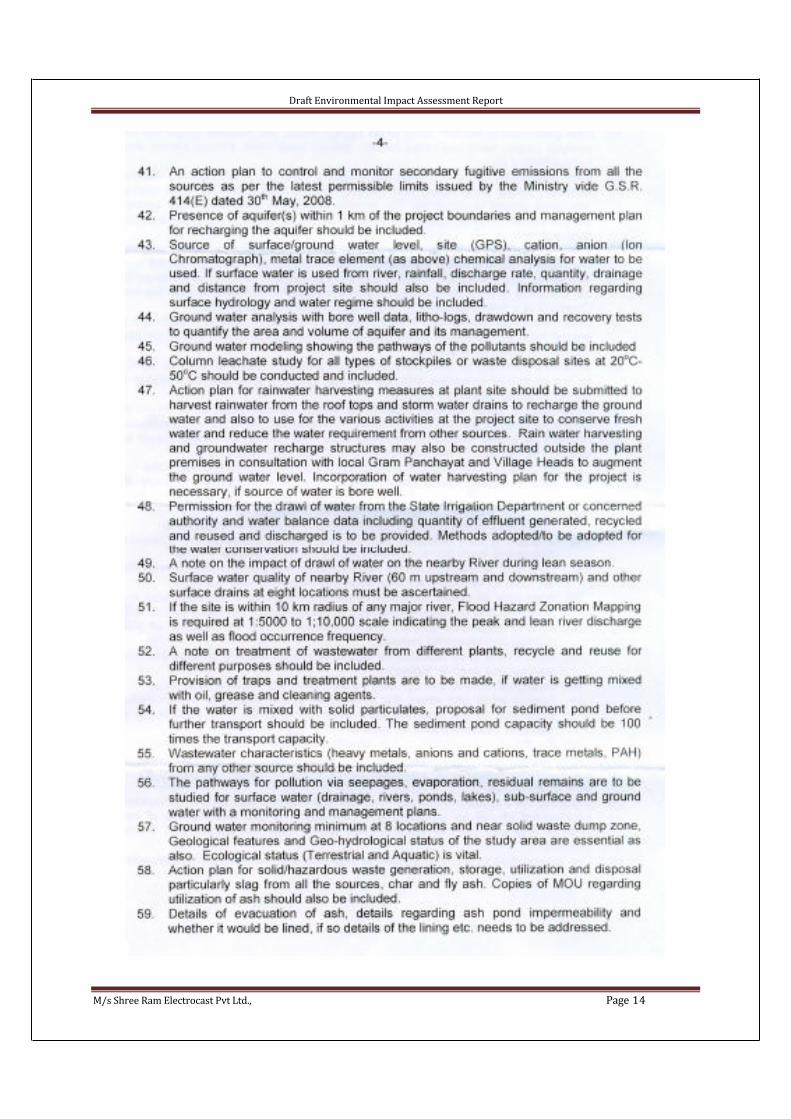
As per MoEF Notification, 14th September 2006, and further amended throughnotification No S.O.3067 (E) dated 1.01.2009, the proposed project is falling under ‘A’ category, based on metallurgical industries production capacity and Inter Stateboundary site location. Hence Shree Ram Electrocast Pvt Ltd submitted the Form-I in the prescribed format to MoEF, Govt of India, New Delhi. Subsequently the proposalwas considered by the Expert Appraisal Committee (Industry) in the 28th Meeting held on 27th September, 2011. Based on the information furnished and presentation before MoEF committee at New Delhi by the proponent, the TORs recommended by theCommittee vide letter No: F. No. J-11011/442/2011-IA-II (I) dated 14th October, 2011is also included in the present Environmental Impact Assessment (EIA) andEnvironmental Management Plan (EMP).
The purpose of the preparation of Environment Impact Assessment (EIA) report is not only to obtain Environment Clearance from Ministry of Environment & Forests, Govt. of India, New Delhi, but also to understand the likely impacts and to take Environment Protection measures during and after commissioning of the project.
The EIA/EMP Report is prepared on the basis of the available secondary data/literature along with the on-site data generated during 3 months study period (Octoberto December, 2011).
1.3 Need of the project and its Importance in the Country
SREPL already have a pig iron plant at Siruguppa to produce 120,000 tons per year. The operating margins of the pig iron producers are expected to reduce due to the decline in pig iron prices because of over supply situation.
The present pig iron plant has metallic blast preheater using blast furnace gas. This will be replaced by hot blast stoves to improve the energy efficiency and operatingparameters. Also Coal dust injection, oxygen enrichment, steam injection, etc areplanned to improve the fuel efficiency and productivity of the blast furnace to 200,000 TPA.
DIP due to its superior characteristics with respect to tensile strength, ductility, impact resistance, corrosion resistance, lower weight, easy handling and longer life hasreplaced cast iron pipes in developed countries in the area of water supply andsanitation. India Government has identified water infrastructure development aspriority area and hence there will be higher demand for the DIP in future.Pig Iron is the main raw material for the DIP. Hence SREPL will have better value addition by installing DIP plant at Siruguppa with a capacity of 200,000 tons per year utilizing the pig iron and steel scrap. The company has already got environmentalclearance for 1,20,000 TPA capcity. Now SREPL is proposing to increase the capacity of DIP plant capacity to 2,00,000 TPA
Draft Environmental Impact Assessment Report
M/s Shree Ram Electrocast Pvt Ltd., Page 21
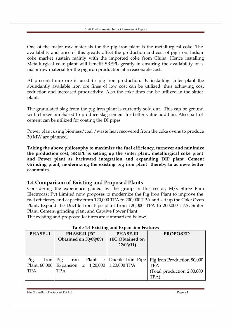
One of the major raw materials for the pig iron plant is the metallurgical coke. The availability and price of this greatly affect the production and cost of pig iron. Indian coke market sustain mainly with the imported coke from China. Hence installingMetallurgical coke plant will benefit SREPL greatly in ensuring the availability of a major raw material for the pig iron production at a reasonable cost.
At present lump ore is used for pig iron production. By installing sinter plant theabundantly available iron ore fines of low cost can be utilized, thus achieving costreduction and increased productivity. Also the coke fines can be utilized in the sinter plant.
The granulated slag from the pig iron plant is currently sold out. This can be ground with clinker purchased to produce slag cement for better value addition. Also part of cement can be utilized for coating the DI pipes
Power plant using biomass/coal /waste heat recovered from the coke ovens to produce30 MW are planned.
Taking the above philosophy to maximize the fuel efficiency, turnover and minimize the production cost, SREPL is setting up the sinter plant, metallurgical coke plant
and Power plant as backward integration and expanding DIP plant, CementGrinding plant, modernizing the existing pig iron plant thereby to achieve better economics
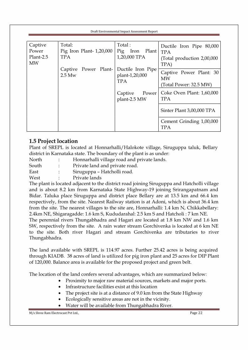
1.4 Comparison of Existing and Proposed PlantsConsidering the experience gained by the group in this sector, M/s Shree RamElectrocast Pvt Limited now proposes to modernize the Pig Iron Plant to improve the fuel efficiency and capacity from 120,000 TPA to 200,000 TPA and set up the Coke Oven Plant, Expand the Ductile Iron Pipe plant from 120,000 TPA to 200,000 TPA, Sinter Plant, Cement grinding plant and Captive Power Plant. The existing and proposed features are summarized below:
Table 1.4 Existing and Expansion Features
PHASE –I PHASE-II (EC Obtained on 30/09/09)
PHASE-III(EC Obtained on
22/06/11)
PROPOSED
Pig IronPlant: 60,000TPA
Pig Iron Plant :Expansion to 1,20,000TPA
Ductile Iron Pipe1,20,000 TPA
Pig Iron Production 80,000 TPA(Total production 2,00,000 TPA)
Draft Environmental Impact Assessment Report
M/s Shree Ram Electrocast Pvt Ltd., Page 22
Ductile Iron Pipe 80,000TPA(Total production 2,00,000 TPA)
Captive Power Plant: 30MW(Total Power: 32.5 MW)
Coke Oven Plant: 1,60,000 TPA
Sinter Plant 3,00,000 TPA
CaptivePowerPlant-2.5MW
Total:Pig Iron Plant- 1,20,000 TPA
Captive Power Plant-2.5 Mw
Total :Pig Iron Plant1,20,000 TPA
Ductile Iron Pipeplant-1,20,000TPA
Captive Powerplant-2.5 MW
Cement Grinding 1,00,000 TPA
1.5 Project locationPlant of SREPL is located at Honnarhalli/Halokote village, Siruguppa taluk, Bellary district in Karnataka state. The boundary of the plant is as under:North : Honnarhalli village road and private lands.South : Private land and private road.East : Siruguppa – Hatcholli road.West : Private lands The plant is located adjacent to the district road joining Siruguppa and Hatcholli village and is about 8.2 km from Karnataka State Highway-19 joining Srirangapatnam and Bidar. Taluka place Siruguppa and district place Bellary are at 13.5 km and 66.4 km respectively, from the site. Nearest Railway station is at Adoni, which is about 36.4 km from the site. The nearest villages to the site are, Honnarhalli: 1.4 km N, Chikkabellary: 2.4km NE, Shigaragadde: 1.6 km S, Kududarahal: 2.5 km S and Hatcholi : 7 km NE. The perennial rivers Thungabhadra and Hagari are located at 1.8 km NW and 1.6 km SW, respectively from the site. A rain water stream Gorchivenka is located at 6 km NE to the site. Both river Hagari and stream Gorchivenka are tributaries to riverThungabhadra.
The land available with SREPL is 114.97 acres. Further 25.42 acres is being acquired through KIADB. 38 acres of land is utilized for pig iron plant and 25 acres for DIP Plant of 120,000. Balance area is available for the proposed project and green belt.
The location of the land confers several advantages, which are summarized below:
• Proximity to major raw material sources, markets and major ports. • Infrastructure facilities exist at this location
• The project site is at a distance of 9.0 km from the State Highway • Ecologically sensitive areas are not in the vicinity.
• Water will be available from Thungabhadra River.

Draft Environmental Impact Assessment Report
M/s Shree Ram Electrocast Pvt Ltd., Page 23
• Electric power will be from the GESCOM Substation at Sirugupa.
• Housing colonies, educational facilities, recreational facilities and other amenities are available at Siruguppa/Bellary.
Considering the above, the location at Honnarhalli/Halokote village is consideredsuitable for the proposed project.
Table 1.5 Proposed Project Details
Sl.No Items Particulars
1 Objective of theProject
Expansion of Pig Iron Plant from 1,20,000 to2,00,000 TPACoke Oven Plant - 1,60,000 TPACaptive Power Plant - 30 MWExpansion of Ductile Iron Pipe Plant from1,20,000 to 2,00,000 TPASinter Plant– 3,00,000 TPACement Grinding Plant – 1,00,000TPA
2 Promoters M/s. Shree Ram Electro cast Pvt. Ltd.
3 Investment forExpansion
415 Crores
4 Project location Sy.No.s 80, 81/A3, 95/A1, 95/A3, 96/A1, 96/A3, 97/1, 97/3, 98/A/1A, 98/A/1B, 98/A3, 98/B1,98/B3, 98/C1,98/C3, 98/D1, 98/D3, 99, 100, 103, 104, 105 and 106 of Honnarahalli Village and Sy, No. 57/C/1, 57/D/1, 57/A/1A, 57/A/2A,57/A/3A, 57/B/A, 57/A/4A, 77/A, 77/B, 78/A and 78/B of Halkote Village, Post – Hatcholi,Taluk- Siruguppa, Dist.- Bellary, Karnataka - 583 114
5 Extent of land The land available with SREPL is 114.97 acres.Proposed additional land to be acquired through KIADB is 25.42 acres.
6 Category ofProject
A
7 Water demandand Source
Existing water consumption 1200 KLD (PIG Iron plant-500 KLD, DIP Plant- 700 KLD) Proposed plant requirement 2215 KLDTotal water requirement after expansion = 3415KLD.

Draft Environmental Impact Assessment Report
M/s Shree Ram Electrocast Pvt Ltd., Page 24
Source: Tungabhadra river. Withdrawalpermission for 4150 KLD for the expansionseeking from Government. (Order No: CI 57 SPI 2011, Bangalore Dated 25.02.2011.)
8 Power demand 26000 KVA after expansion
Table 1.6 Environmental settings around the proposed project site (Within 10 kms radius)
Sl. No Feature Particulars
1. Location Honnarahalli village, Siruguppa taluk, district, Karnataka.
2. Present land use Industrial and agricultural land
3. Altitude above meanMSL
475 m
4. Temp.0C (Range) Max. 31.0 to 41.2 and Min. 10.7 to 20.6
5. Mean Annual humidity& RF
65 % and 645 mm
6. Soil type Black cotton mixed loamy soil
7. Topography Plain terrain sloping towards NW
8. Nearest State Highway S.H.-19(Srirangapatna - Bidar), 8.2 km,
9. Nearest railway station None with in 10 km radius (Adoni-36.4 km in NE direction (S.C. Railway)
10. Nearest airport None with in 10 km radius. Bellary air strip; 63 kms (S) Hyderabad air port is about 227 km in NE.
11. Nearest village Honnarahalli, 1.4 km. in N
12. Nearest town Siruguppa 13.5 km, SW
13. Nearest major city None with in 10 km radius, Bellary, 66.4 km, SW
14. Nearest river Tungabhadra river , 1.8 Km , NW
15. Nearest industry None with in 10 km radius, Siruguppa Sugar 12 km.
16. Sensitive locations No Archeological structures, Historical places, ProtectedForests, Sanctuaries and Biosphere Reserves present within 10 kms from the Industry.
Draft Environmental Impact Assessment Report
M/s Shree Ram Electrocast Pvt Ltd., Page 25
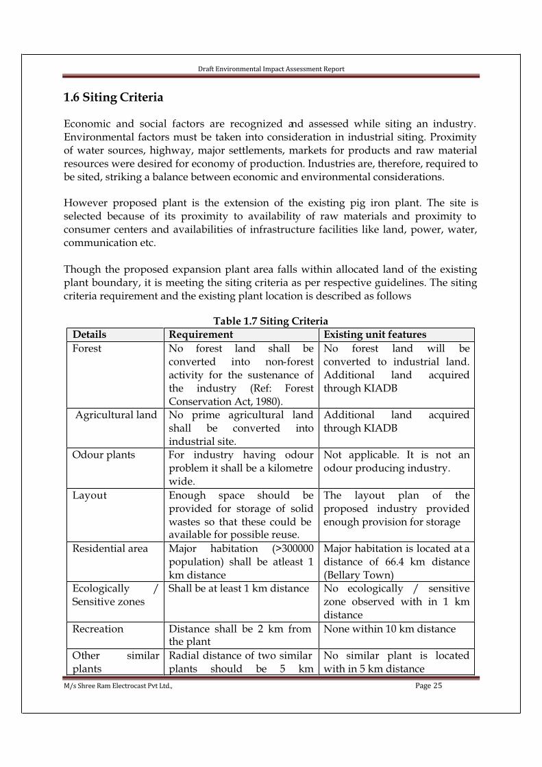
1.6 Siting Criteria
Economic and social factors are recognized and assessed while siting an industry. Environmental factors must be taken into consideration in industrial siting. Proximity of water sources, highway, major settlements, markets for products and raw material resources were desired for economy of production. Industries are, therefore, required to be sited, striking a balance between economic and environmental considerations.
However proposed plant is the extension of the existing pig iron plant. The site isselected because of its proximity to availability of raw materials and proximity to consumer centers and availabilities of infrastructure facilities like land, power, water, communication etc.
Though the proposed expansion plant area falls within allocated land of the existing plant boundary, it is meeting the siting criteria as per respective guidelines. The siting criteria requirement and the existing plant location is described as follows
Table 1.7 Siting Criteria
Details Requirement Existing unit features
Forest No forest land shall beconverted into non-forestactivity for the sustenance ofthe industry (Ref: ForestConservation Act, 1980).
No forest land will beconverted to industrial land.Additional land acquiredthrough KIADB
Agricultural land No prime agricultural landshall be converted intoindustrial site.
Additional land acquiredthrough KIADB
Odour plants For industry having odourproblem it shall be a kilometre wide.
Not applicable. It is not anodour producing industry.
Layout Enough space should beprovided for storage of solidwastes so that these could be available for possible reuse.
The layout plan of theproposed industry providedenough provision for storage
Residential area Major habitation (>300000population) shall be atleast 1km distance
Major habitation is located at a distance of 66.4 km distance(Bellary Town)
Ecologically /Sensitive zones
Shall be at least 1 km distance No ecologically / sensitivezone observed with in 1 kmdistance
Recreation Distance shall be 2 km from the plant
None within 10 km distance
Other similarplants
Radial distance of two similar plants should be 5 km
No similar plant is locatedwith in 5 km distance

Draft Environmental Impact Assessment Report
M/s Shree Ram Electrocast Pvt Ltd., Page 26
distance
High way The distance from the NHshall be 0.5 Km
National High Way: 63 found at a distance of 60 km
State High way The distance from the SH shall be 0.5 Km
State High way is located 8.2km distance
Fig: 1.1 Toposheet of the area showing the location of the industry with 15 kms radius demarcation.
15 kms Radius

Draft Environmental Impact Assessment Report
M/s Shree Ram Electrocast Pvt Ltd., Page 27
1.7 List of Industries The following industries are located within 25 kms from the proposed project site.
Table 1.8 List of IndustriesSl No Name of the Industry Distance, Km
1 Picheshwar Rao Pipe company 3.3 (W)
2 Kothari Sugars (P) Ltd., 11.6 (SW)
3 Shree BhagyaLakshmi Industries 11.7 (SW)
4 Maruthi rice Industries 12.3 (SW)
5 Sri Balaji Rice Industries 21.6 (W)
6 Balaji Brick Industries 21.52 (W)
1.8 Scope of the WorkThe EIA study includes determination of baseline conditions, assessment of the Impacts on the environment due to the construction and operation of the proposed project and making recommendations on the preventive measures to be taken, to minimize the impact on the environment to acceptable levels. A suitable post-study monitoringprogram will be outlined. Preparation of Environment Management Plan will be given based on the emissions and feasibility report. The scope of work is prepared based on MoEF / CPCB guidelines and tabulated below.
Table 1.9 Scope of work
EnvironmentalAttributes
No ofLocations
Observations
Meteorology
1 Hourly observations for Temperature, RelativeHumidity, Wind direction, wind speed & Rain fallduring 3 month study period
AAQ 8 For all the parameters as per National Ambient Air Quality Standards, 2009 for 24 hours duration, 2 times in each week during 12-week study period
Water 9 3 Surface water Locations 6 Ground water locations (including the place near to the plant site) Parameters that are analyzed are as per Analysis of Drinking Water Quality had been carried out
Noise 6 Day and night noise levels once in every location
Soil 05 At 5 locations.
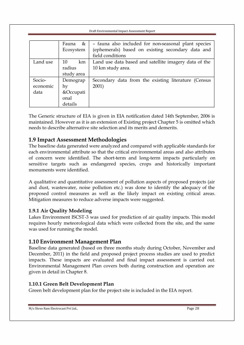
Ecology Flora- Total study period is 90days. However predicted flora
Draft Environmental Impact Assessment Report
M/s Shree Ram Electrocast Pvt Ltd., Page 28
Fauna &Ecosystem
– fauna also included for non-seasonal plant species(ephemerals) based on existing secondary data andfield conditions
Land use 10 kmradiusstudy area
Land use data based and satellite imagery data of the 10 km study area.
Socio-economicdata
Demography&Occupationaldetails
Secondary data from the existing literature (Census2001)
The Generic structure of EIA is given in EIA notification dated 14th September, 2006 is maintained. However as it is an extension of Existing project Chapter 5 is omitted which needs to describe alternative site selection and its merits and demerits.
1.9 Impact Assessment MethodologiesThe baseline data generated were analyzed and compared with applicable standards for each environmental attribute so that the critical environmental areas and also attributes of concern were identified. The short-term and long-term impacts particularly onsensitive targets such as endangered species, crops and historically importantmonuments were identified.
A qualitative and quantitative assessment of pollution aspects of proposed projects (air and dust, wastewater, noise pollution etc.) was done to identify the adequacy of the proposed control measures as well as the likely impact on existing critical areas.Mitigation measures to reduce adverse impacts were suggested.
1.9.1 Air Quality ModelingLakes Environment ISCST-3 was used for prediction of air quality impacts. This model requires hourly meteorological data which were collected from the site, and the same was used for running the model.
1.10 Environment Management PlanBaseline data generated (based on three months study during October, November and December, 2011) in the field and proposed project process studies are used to predict impacts. These impacts are evaluated and final impact assessment is carried out.Environmental Management Plan covers both during construction and operation are given in detail in Chapter 8.
1.10.1 Green Belt Development PlanGreen belt development plan for the project site is included in the EIA report.

Draft Environmental Impact Assessment Report
M/s Shree Ram Electrocast Pvt Ltd., Page 29
1.11 Disaster Management Plan and Occupational SafetyA Disaster Management Plan (DMP) for dealing emergency situation arising due to fire, explosion, leakages of hazardous substances, etc. in the plant site is prepared. The plan includes storage, handling, transportation etc. for the hazardous materials to be used in the proposed project.
Occupational risk involved during construction and operation of the plant is assessed and necessary safety and protective measures are spelt out.
1.12 Post Study Monitoring PlanThe Post Project Monitoring (PPM) plan is prepared considering the following:
• The proposed pollution control measures for air, wastewater, noise and solid waste (hazardous/non-hazardous) disposal;
• Waste minimization; wastewater management, waste reuse andresource recovery; waste segregation to make the treatment anddisposal cost-effective

Draft Environmental Impact Assessment Report
M/s Shree Ram Electrocast Pvt Ltd., Page 30
CHAPTER II- PROJECT DESCRIPTION
2.1 IntroductionThe proposed project is an expansion project with the following units:
• Pig iron plant modernization to improve the fuel efficiency and increase in production capacity from 120,000 TPA to 2,00,000TPA
• Coke Oven Plant - 160,000 TPA
• Captive Power Plant - 30 MW
• Expansion of Ductile Iron Pipe Plant- from 1,20,000 TPA to 200,000 TPA• Sinter Plant – 300,000 TPA
• Cement Grinding Plant – 100,000 TPA
at Sy.No.s 80, 81/A3, 95/A1, 95/A3, 96/A1, 96/A3, 97/1, 97/3, 98/A/1A, 98/A/1B, 98/A3, 98/B1, 98/B3, 98/C1,98/C3, 98/D1, 98/D3, 99, 100, 103, 104, 105 and 106 of Honnarahalli Village and Sy, No. 57/C/1, 57/D/1, 57/A/1A, 57/A/2A, 57/A/3A,57/B/A, 57/A/4A, 77/A, 77/B, 78/A and 78/B of Halkote Village, Post – Hatcholi, Taluk- Siruguppa, Dist.- Bellary, Karnataka
2.2 LocationPig iron plant of SREPL is located at Honnarhalli/Halkote village, Siruguppa taluk, Bellary district in Karnataka state. The boundary of the plant is as under:
North : Honnarhalli village road and private lands.South : Private land and private road.East : Siruguppa – Hatcholli road.West : Private lands
The plant is located adjacent to the district road joining Siruguppa and Hatcholli village and is about 8.2 km from Karnataka State Highway-19 joining Srirangapatnam and Bidar. Taluka place Siruguppa and district place Bellary are at 13.5 km and 66.4 km respectively, from the site. Nearest Railway station is at Adoni, which is about 36.4 km from the site. The nearest villages to the site are, Honnarhalli: 1.4 km N, Chikkabellary: 2.4km NE, Shigaragadde: 1.6 km S, Kududarahal: 2.5 km S and Hatcholi : 7 km NE.
The perennial rivers Thungabhadra and Hagari are located at 1.8 km NW and 1.6 km SW, respectively from the site. A rain water stream Gorchivenka is located at 6 km NE to the site. Both river Hagari and stream Gorchivenka are tributaries to riverThungabhadra.
The land available with SREPL is about 114.97 acres. Further 25.42 acres is being acquired through KIADB. 38 acres of land is utilized for pig iron plant and 25 acres for DIP Plant of 120,000 TPA capacity. The balance area will be available for the proposed
Draft Environmental Impact Assessment Report
M/s Shree Ram Electrocast Pvt Ltd., Page 31
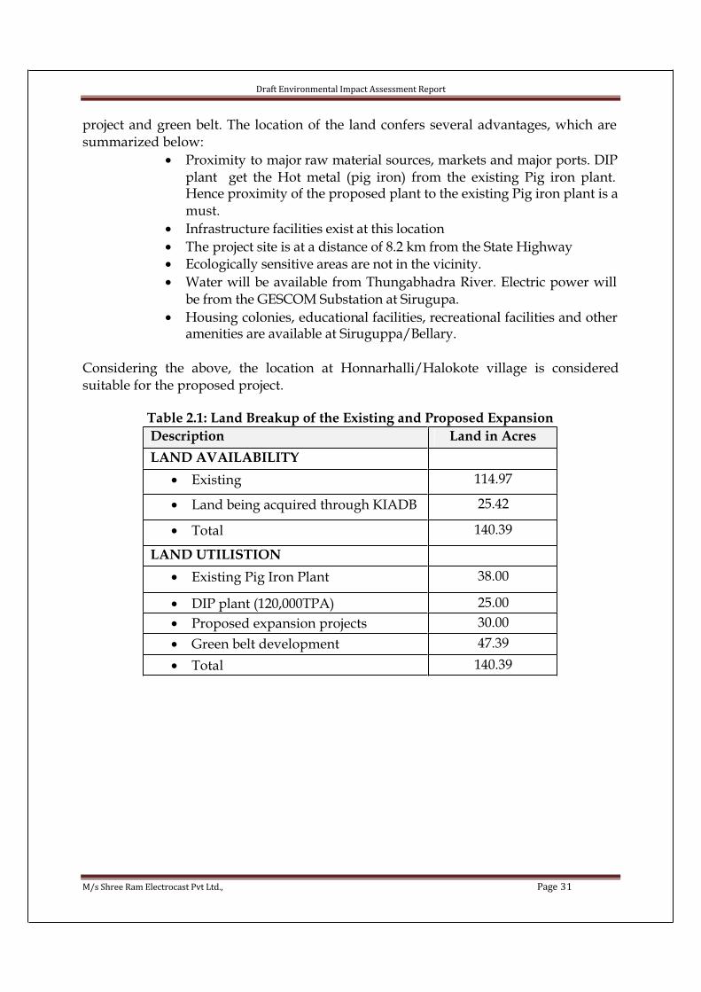
project and green belt. The location of the land confers several advantages, which are summarized below:
• Proximity to major raw material sources, markets and major ports. DIP plant get the Hot metal (pig iron) from the existing Pig iron plant. Hence proximity of the proposed plant to the existing Pig iron plant is a must.
• Infrastructure facilities exist at this location
• The project site is at a distance of 8.2 km from the State Highway • Ecologically sensitive areas are not in the vicinity.
• Water will be available from Thungabhadra River. Electric power will be from the GESCOM Substation at Sirugupa.
• Housing colonies, educational facilities, recreational facilities and other amenities are available at Siruguppa/Bellary.
Considering the above, the location at Honnarhalli/Halokote village is consideredsuitable for the proposed project.
Table 2.1: Land Breakup of the Existing and Proposed Expansion
Description Land in Acres
LAND AVAILABILITY
• Existing 114.97
• Land being acquired through KIADB 25.42
• Total 140.39
LAND UTILISTION
• Existing Pig Iron Plant 38.00
• DIP plant (120,000TPA) 25.00
• Proposed expansion projects 30.00
• Green belt development 47.39
• Total 140.39
Draft Environmental Impact Assessment Report
M/s Shree Ram Electrocast Pvt Ltd., Page 32
Fig 2.1Location of the proposed project site
Draft Environmental Impact Assessment Report
M/s Shree Ram Electrocast Pvt Ltd., Page 33
Fig 2.2 Toposheet of the area showing the location of the proposed expansion project site (Toposheet No.s: 57 A/13, 57 A/14, 57 E/1, 57 E/2 Scale 1:50,000)
10 kms Radius
Draft Environmental Impact Assessment Report
M/s Shree Ram Electrocast Pvt Ltd., Page 34
Fig 2.3 Aerial view of the proposed project site.Existing units
Proposed
units
Draft Environmental Impact Assessment Report
M/s Shree Ram Electrocast Pvt Ltd., Page 35
Fig 2.4 Aerial view of the proposed project site with 10 kms demarcation

Draft Environmental Impact Assessment Report
M/s Shree Ram Electrocast Pvt Ltd., Page 36
Fig 2.5 Satellite imagery of the study area
(Source: Dr. Anantha Rama, GIS consultant)

Draft Environmental Impact Assessment Report
M/s Shree Ram Electrocast Pvt Ltd., Page 37
Fig 2.6 Photos showing the existing Pig Iron Unit
North: Barren landEast: Pig Iron unitWest: RoadSouth: Vacant land

Draft Environmental Impact Assessment Report
M/s Shree Ram Electrocast Pvt Ltd., Page 38
Fig 2.7 Photos showing site surrounding photograph
North: Barren LandWest: Agricultural landEast: Barren LandSouth: Agricultural land
Draft Environmental Impact Assessment Report
M/s Shree Ram Electrocast Pvt Ltd., Page 39
Fig 2.8 Photos showing the proposed project site
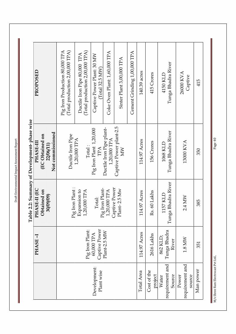
Dra
ft E
nv
iro
nm
en
tal
Imp
act
Ass
ess
me
nt
Re
po
rt
M/
s S
hre
e R
am
Ele
ctro
cast
Pv
t L
td.,
Pa
ge
40
Ta
ble
2.2
: S
um
ma
ry o
f D
ev
elo
pm
en
t- p
ha
se w
ise
PH
AS
E–I
PH
AS
E-I
I (E
C
Ob
tain
ed
on
3
0/0
9/0
9)
PH
AS
E-I
II
(EC
Ob
tain
ed
on
2
2/0
6/1
1)
No
t co
mm
issi
on
ed
PR
OP
OS
ED
Pig
Iro
n P
rod
uct
ion
80,
000
TP
A(T
ota
l p
rod
uct
ion
2,0
0,00
0 T
PA
)
Du
ctil
e Ir
on
Pip
e 80
,000
TP
A(T
ota
l p
rod
uct
ion
2,0
0,00
0 T
PA
)
Cap
tiv
e P
ow
er P
lan
t: 3
0 M
W(T
ota
l 32
.5 M
W)
Co
ke
Ov
en P
lan
t: 1
,60,
000
TP
A
Sin
ter
Pla
nt
3,00
,000
TP
A
Dev
elo
pm
ent:
Pla
nt
wis
e
Pig
Iro
n P
lan
t:
60
,00
0 T
PA
Cap
tiv
e P
ow
er
Pla
nt-
2.5
MW
Pig
Iro
n P
lan
t :
Ex
pan
sio
n t
o
1,2
0,0
00
TP
A
To
tal:
Pig
Iro
n P
lan
t-1
,20
,00
0 T
PA
Cap
tiv
e P
ow
er
Pla
nt-
2.5
Mw
Du
ctil
e Ir
on
Pip
e1
,20
,00
0 T
PA
To
tal
:P
ig I
ron
Pla
nt
1,2
0,00
0 T
PA
Du
ctil
e Ir
on
Pip
e p
lan
t-1
,20
,00
0 T
PA
Ca
pti
ve
Po
wer
pla
nt-
2.5
MW
Cem
ent
Gri
nd
ing
1,0
0,00
0 T
PA
To
tal
Are
a11
4.97
Acr
es11
4.97
Acr
es11
4.97
Acr
es14
0.39
acr
es
Co
st o
f th
e p
roje
ct26
16 L
akh
sR
s. 6
0 L
akh
s15
6 C
rore
s41
5 C
rore
s
Wat
erre
qu
irem
ent
and
S
ou
rce
862
KL
D;
Tu
ng
a B
had
ra
Riv
er
11
57
KL
DT
un
ga
Bh
ad
ra R
iver
1068
KL
DT
un
ga
Bh
ad
ra R
iver
41
50
KL
DT
un
ga
Bh
ad
ra R
iver
Po
wer
req
uir
emen
t an
d
sou
rce
1.8
MW
2.4
MW
13
00
0 K
VA
26
00
0 K
VA
Cap
tiv
e
Ma
n p
ow
er35
138
535
041
5
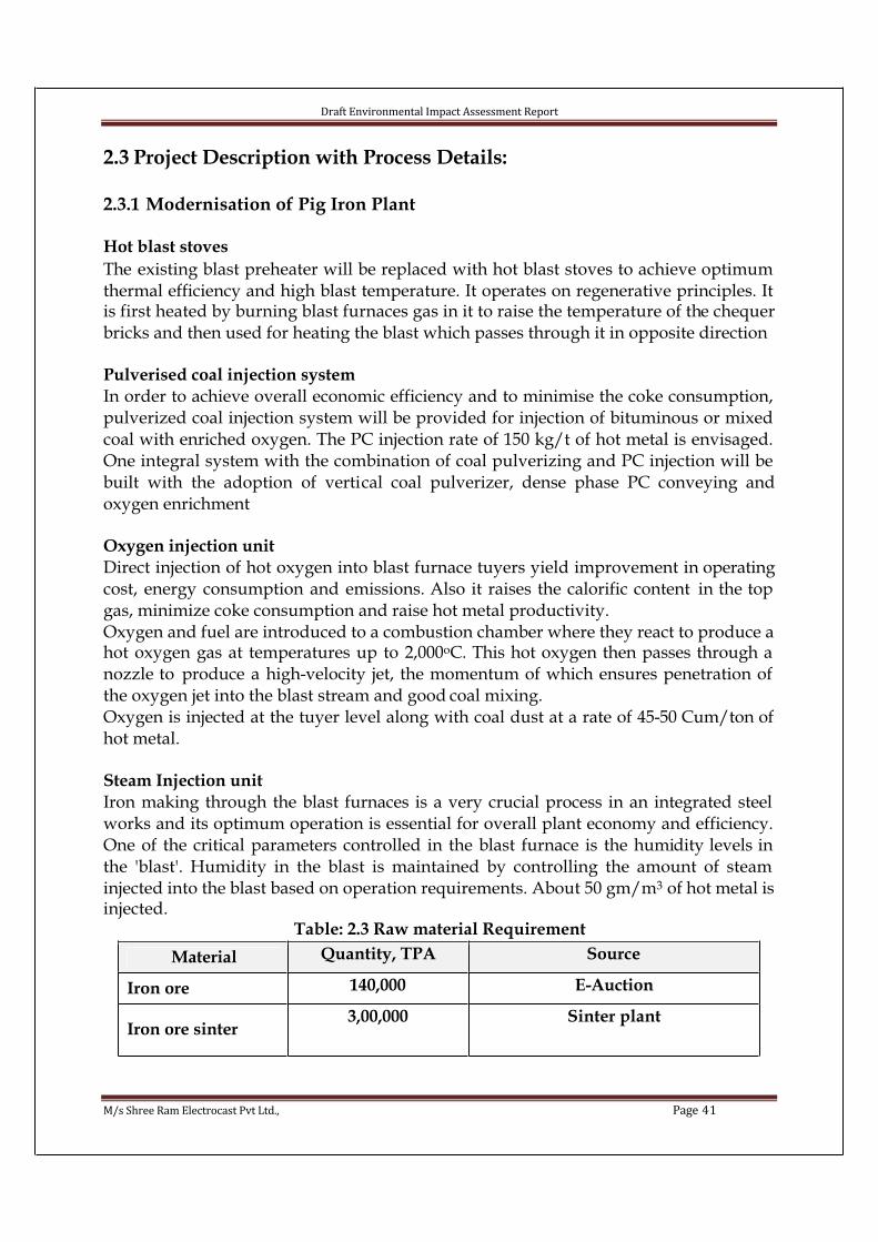
Draft Environmental Impact Assessment Report
M/s Shree Ram Electrocast Pvt Ltd., Page 41
2.3 Project Description with Process Details:
2.3.1 Modernisation of Pig Iron Plant
Hot blast stoves
The existing blast preheater will be replaced with hot blast stoves to achieve optimum thermal efficiency and high blast temperature. It operates on regenerative principles. It is first heated by burning blast furnaces gas in it to raise the temperature of the chequer bricks and then used for heating the blast which passes through it in opposite direction
Pulverised coal injection system
In order to achieve overall economic efficiency and to minimise the coke consumption, pulverized coal injection system will be provided for injection of bituminous or mixed coal with enriched oxygen. The PC injection rate of 150 kg/t of hot metal is envisaged. One integral system with the combination of coal pulverizing and PC injection will be built with the adoption of vertical coal pulverizer, dense phase PC conveying andoxygen enrichment
Oxygen injection unit
Direct injection of hot oxygen into blast furnace tuyers yield improvement in operatingcost, energy consumption and emissions. Also it raises the calorific content in the top gas, minimize coke consumption and raise hot metal productivity. Oxygen and fuel are introduced to a combustion chamber where they react to produce a hot oxygen gas at temperatures up to 2,000oC. This hot oxygen then passes through a nozzle to produce a high-velocity jet, the momentum of which ensures penetration of the oxygen jet into the blast stream and good coal mixing.Oxygen is injected at the tuyer level along with coal dust at a rate of 45-50 Cum/ton of hot metal.
Steam Injection unit
Iron making through the blast furnaces is a very crucial process in an integrated steel works and its optimum operation is essential for overall plant economy and efficiency. One of the critical parameters controlled in the blast furnace is the humidity levels in the 'blast'. Humidity in the blast is maintained by controlling the amount of steam injected into the blast based on operation requirements. About 50 gm/m3 of hot metal is injected.
Table: 2.3 Raw material Requirement
Material Quantity, TPA Source
Iron ore 140,000 E-Auction
Iron ore sinter3,00,000 Sinter plant

Draft Environmental Impact Assessment Report
M/s Shree Ram Electrocast Pvt Ltd., Page 42
Coke1,55,000 Coke oven plant
Lime stone 35,000 Bagalkot
Dolomite 25,000 Lokapur
Manganese 3,000 Sandur
Quartz 11,000 Hospet
Water 250 KLD Tungabhadra River
Power 1000 KVA Captive
Steam 50 gm/m3 of hot metal Captive
Table 2.4 Chemical characteristics of Iron ore
Table 2.5 Chemical characteristics of Limestone
Table 2.6 Chemical characteristics of Dolomite

Draft Environmental Impact Assessment Report
M/s Shree Ram Electrocast Pvt Ltd., Page 43
Table 2.7 Chemical characteristics of Quartz
Table 2.8: Material balance
INPUT OUTPUT
Material Quantity, TPA Material Quantity, TPA
Iron ore 140,000 Pig iron 200,000
Iron ore sinter 3,00,000 Iron ore fines 97,800
Coke 1,55,000 Coke fines 11,000
Lime stone 35,000 B.F.Slag 58,000
Dolomite 25,000 GCP dust 6,720
Mn. 3,000 GCP sludge 5, 430
Quartz 11,000 P.I.Scrap 15,330
BF Gas 66,600 Nm3 / hr
Table 2.9 BF gas generation and utilization
Sl.No Details Quantity,Nm3 / hr
1 Blast Furnace gas generated after expansion to 200,000 TPA 66,600
2 B.F.Gas required for Stoves/air preheating for BF 28,000
3 B.F gas required for Power plant boiler 22,000
4 BF gas for sinter plant 16,600
2.3.2 Coke Oven PlantShree Ram Electrocast Pvt Ltd plans to set-up a heat recovery type stamp chargedcoking plant to produce about 160,000 tons of gross coke per year, generating electricity making use of the waste gas of coking plant.
The production facilities will contain: coal preparation plant, coking plant and coke screening plant. The auxiliary production facilities will include central control room, central testing room; infrastructure works include main power substation, coking plant substation, water supply and sewerage works, fire protection, etc.
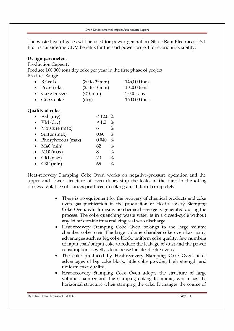
Draft Environmental Impact Assessment Report
M/s Shree Ram Electrocast Pvt Ltd., Page 44
The waste heat of gases will be used for power generation. Shree Ram Electrocast Pvt. Ltd. is considering CDM benefits for the said power project for economic viability.
Design parameters
Production CapacityProduce 160,000 tons dry coke per year in the first phase of project Product Range
• BF coke (80 to 25mm) 145,000 tons• Pearl coke (25 to 10mm) 10,000 tons
• Coke breeze (<10mm) 5,000 tons
• Gross coke (dry) 160,000 tons
Quality of coke
• Ash (dry) < 12.0 %• VM (dry) < 1.0 %
• Moisture (max) 6 %
• Sulfur (max) 0.60 %• Phosphorous (max) 0.040 %
• M40 (min) 82 %• M10 (max) 8 %
• CRI (max) 20 %
• CSR (min) 65 %
Heat-recovery Stamping Coke Oven works on negative-pressure operation and the upper and lower structure of oven doors stop the leaks of the dust in the cokingprocess. Volatile substances produced in coking are all burnt completely.
• There is no equipment for the recovery of chemical products and coke oven gas purification in the production of Heat-recovery StampingCoke Oven, which means no chemical sewage is generated during the process. The coke quenching waste water is in a closed-cycle without any let off outside thus realizing real zero discharge.
• Heat-recovery Stamping Coke Oven belongs to the large volumechamber coke oven. The large volume chamber coke oven has many advantages such as big coke block, uniform coke quality, few numbers of input coal/output coke to reduce the leakage of dust and the power consumption as well as to increase the life of coke ovens.
• The coke produced by Heat-recovery Stamping Coke Oven holdsadvantages of big coke block, little coke powder, high strength anduniform coke quality.
• Heat-recovery Stamping Coke Oven adopts the structure of largevolume chamber and the stamping coking technique, which has thehorizontal structure when stamping the cake. It changes the course of
Draft Environmental Impact Assessment Report
M/s Shree Ram Electrocast Pvt Ltd., Page 45
coke oven gas and chemical products flowing in the chamber and the weakly coking coal can be made use of largely. 40 ~ 45% non coking coal can be mixed to the coking coal, which is of great significance to the conservation of coking coal resources.
• Stamping machine is the key coking equipment, the performance ofwhich directly affects the coke quality and normal production of coke ovens. Heat-recovery Stamping Coke Oven adopts the hydraulicstamping technology. This technology makes the cake have suchfeatures as large and uniform density, smooth surface, low noise and little maintenance.
• Heat-recovery Stamping Coke Oven eliminates the coke guide cars used in conventional coke ovens and collects the coke horizontally, which is effective in decreasing the dust falling from the process of output coke and increasing the block of coke.
• All material generated in the coking process is burnt completely inside the coke oven and turns into high temperature waste gas, which is used for steam/power generation by the heat recovery boiler. The electricity can be largely generated in the coking process with a little waterconsumption.
The process flow chart of heat recovery stamping coke oven is given below:
Fig 2.9 Flow chart of heat recovery stamping coke oven
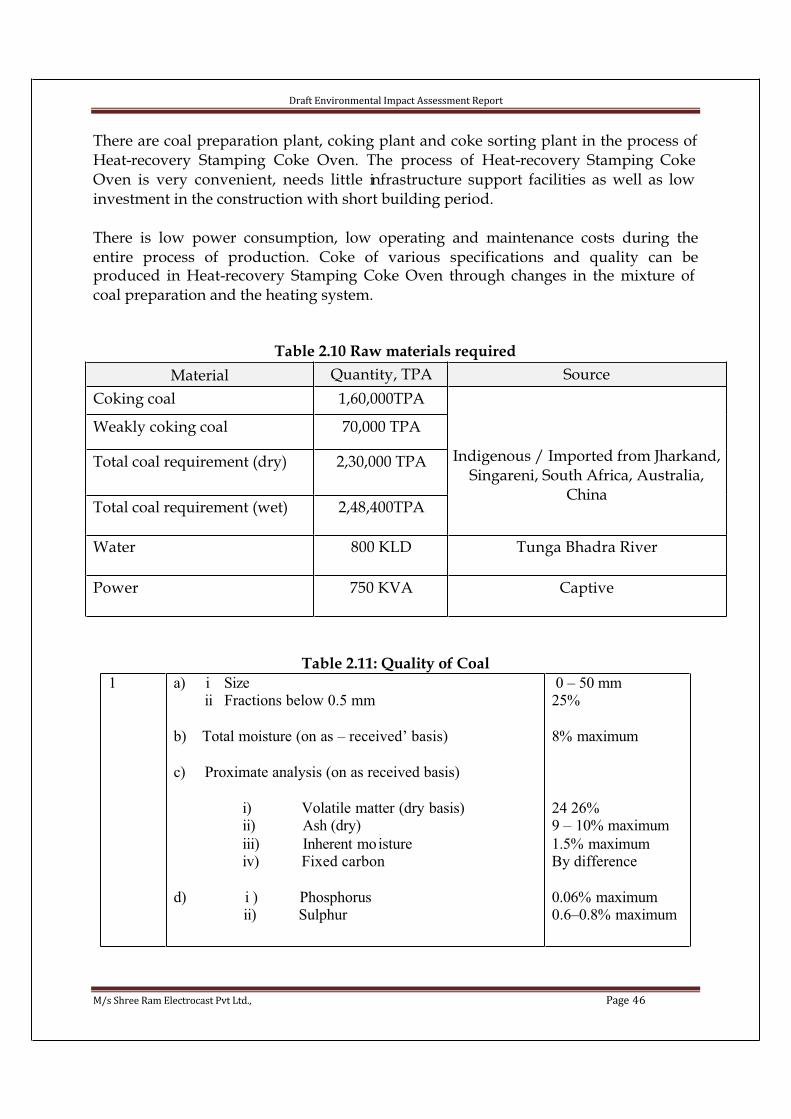
Draft Environmental Impact Assessment Report
M/s Shree Ram Electrocast Pvt Ltd., Page 46
There are coal preparation plant, coking plant and coke sorting plant in the process of Heat-recovery Stamping Coke Oven. The process of Heat-recovery Stamping Coke Oven is very convenient, needs little infrastructure support facilities as well as low investment in the construction with short building period.
There is low power consumption, low operating and maintenance costs during theentire process of production. Coke of various specifications and quality can beproduced in Heat-recovery Stamping Coke Oven through changes in the mixture of coal preparation and the heating system.
Table 2.10 Raw materials required
Material Quantity, TPA Source
Coking coal 1,60,000TPA
Weakly coking coal 70,000 TPA
Total coal requirement (dry) 2,30,000 TPA
Total coal requirement (wet) 2,48,400TPA
Indigenous / Imported from Jharkand,Singareni, South Africa, Australia,
China
Water 800 KLD Tunga Bhadra River
Power 750 KVA Captive
Table 2.11: Quality of Coal
1 a) i Size ii Fractions below 0.5 mm
b) Total moisture (on as – received’ basis)
c) Proximate analysis (on as received basis)
i) Volatile matter (dry basis)ii) Ash (dry)
iii) Inherent moistureiv) Fixed carbon
d) i ) Phosphorus ii) Sulphur
0 – 50 mm25%
8% maximum
24 26%9 – 10% maximum
1.5% maximumBy difference
0.06% maximum0.6–0.8% maximum

Draft Environmental Impact Assessment Report
M/s Shree Ram Electrocast Pvt Ltd., Page 47
Table 2.12 Material balance – Coke Oven plant
INPUT OUTPUT
Material Quantity, TPA Material Quantity, TPA
Coking coal 1,60,000TPA Gross Coke 160,000
Weakly coking coal 70,000 TPA Flue gas 96,000 Nm3/hr
Total coal requirement(dry)
2,30,000 TPA
Total coal requirement(wet)
2,48,400TPA
2.3.3 Power PlantThe proposed 30.0 MW Power Plant will have 2 x 22 TPH (MCR) Waste Heat Recovery Boilers which will utilize the sensible heat of flue gas from the Coke oven plant and one AFBC Boiler of 54 x 2 TPH (MCR) using biomass/coal and 2 x 15 MW turbogenerator. Waste gases from the coke oven plant will be let into the waste heat boilers. The boiler will be bi-drum, water tube boiler. The front radiation section is made up of fin welded water walls. Suitable hopper is provided at the bottom of the radiant section forcollection of the dust, which has to be periodically removed for disposal. The gases leaving the radiant section will enter the super heater and then the boiler bank. After this the gas will pass through economizer and the temperature of the gas will bereduced to about 1700C. Then the gas will pass through ESP and ID fan to Chimney. The parameters of the steam at the outlet of the superheater will be 90 kg/cm2 and515+/-5 0C.108 TPH (MCR) Atmospheric Fluidised Bed Combustion Boiler will be fired withbiomass/coal. The parameters of the steam at the outlet of the superheater will be 90 kg/cm2 and 515+/-5 0C. The AFBC boiler will be a bi-drum water tube boiler with Fluidised Bed Combustion. The furnace is made up of fin welded membrane water walls. Evaporative bed coils are provided in fluidised bed zone. The fluidised bedcombustor comprises of Bed plate with fluidizing air nozzles; fuel nozzles and ash drain pipes. Under bed fuel feeding is proposed for admission of fuel on to the Combustor. Necessary fluidizing air is supplied by a forced draft fan and pneumatic transport air is supplied by primary fan. Ash along with bed material has to be periodically removed from the combustor for disposal. The flue gases leaving the membrane wall furnace enters the convective super heater and then on to boiler bank tubes. The flue gas will enter L.T.Super heater section, bare tube economizer and then to air heater. Now the flue gas temperature will be about 1700C. Then the gas will pass through ESP and ID fan to Chimney.Steam from the boilers will be fed to a common steam header which will ultimately take it to two bleed cum condensing type Steam Turbine Generator each rated for 15 MW at inlet steam parameters of 90 kg/cm2 & 515+/-5 0C. The turbine exhaust will be

Draft Environmental Impact Assessment Report
M/s Shree Ram Electrocast Pvt Ltd., Page 48
condensed in water cooled condenser and the condensate will be taken to de-aerator by condensate extraction pumps.The condensate will be de-aerated in the de-aerator and the temperature will be raised normally with the help of extracted steam from turbine. Provision of heating of condensate in de-aerator by the auxiliary steam coming from main steam headerthrough PRDU will also be envisaged. The feed water will be fed to the economizer of each boiler through a common feed water header by boiler feed pumps
Biomass/Coal for AFBC boiler will be stored in adequate quantity. This will bereclaimed by front end loaders and transferred by belt conveyors to the feedpreparation units and then to the boiler bunker. Bottom ash will be collected and stored in the ash storage area for disposal to Brick manufacturers. Fly ash from economiser, ESP, air preheater, etc will be conveyed to the ash silo for disposal.
Table 2.13 Raw material requirement
Raw material Quantity Source
Coal 1,25,000 TPA Jharkand, Singareni, South Africa,Australia, China
Waste gas from Cokeoven plant
96,000 Nm3/hr Coke oven plant
Water 900 KLD Tunga Bhadra River
Power 4200 KVA Captive
Table 2.14 Chemical characteristics of coal
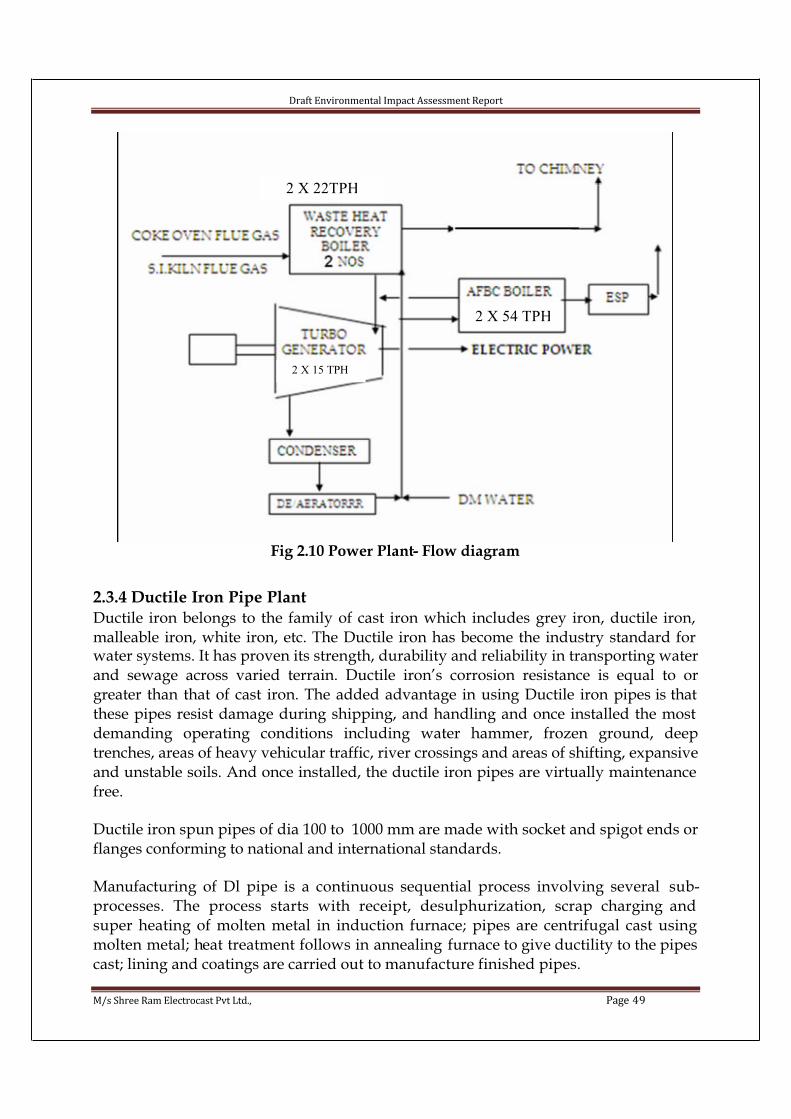
Draft Environmental Impact Assessment Report
M/s Shree Ram Electrocast Pvt Ltd., Page 49
Fig 2.10 Power Plant- Flow diagram
2.3.4 Ductile Iron Pipe PlantDuctile iron belongs to the family of cast iron which includes grey iron, ductile iron, malleable iron, white iron, etc. The Ductile iron has become the industry standard for water systems. It has proven its strength, durability and reliability in transporting water and sewage across varied terrain. Ductile iron’s corrosion resistance is equal to orgreater than that of cast iron. The added advantage in using Ductile iron pipes is that these pipes resist damage during shipping, and handling and once installed the most demanding operating conditions including water hammer, frozen ground, deeptrenches, areas of heavy vehicular traffic, river crossings and areas of shifting, expansiveand unstable soils. And once installed, the ductile iron pipes are virtually maintenance free.
Ductile iron spun pipes of dia 100 to 1000 mm are made with socket and spigot ends or flanges conforming to national and international standards.
Manufacturing of Dl pipe is a continuous sequential process involving several sub-processes. The process starts with receipt, desulphurization, scrap charging and super heating of molten metal in induction furnace; pipes are centrifugal cast using molten metal; heat treatment follows in annealing furnace to give ductility to the pipes cast; lining and coatings are carried out to manufacture finished pipes.
2 X 22TPH
2 X 54 TPH
2 X 15 TPH
Draft Environmental Impact Assessment Report
M/s Shree Ram Electrocast Pvt Ltd., Page 50
Metal Preparation:
The metal shop is equipped with induction furnaces- 5 nos. of 15 ton capacity each and magnesium treatment convertors. Input raw material to the furnace is pig iron. The raw material is charged into the furnace using overhead bay cranes of 50/ 15 Ton – 1 no. and 5 ton – 1 no. capacity. All the cranes are with AC induction motors and are havingvariable speed AC Drives. The cranes are equipped with complete control systemconsisting of motors and variable frequency AC drives and controlgear for alloperations of Long travel, hoist, auxiliary hoist and cross travel. The speed of thedifferent movements is controlled by varying the speed of the AC induction motors by varying the frequency of the AC supply to the AC motor. The control system hasprovision for operating the crane from master controller (cabin) or from remotecontrols. The metal composition and tapping temperature are controlled to the exact specifications before magnesium treatment. The metal is tapped in ladles and shifted from the furnace to the convertor and then to the casting machine using overhead bay cranes. The metal is treated with pure magnesium in controlled conditions. Thetreatment with pure magnesium is optimized to ensure the total nodularity of graphite.
Mould conditioning:
The permanent moulds are inspected at regular intervals and conditioned at the mould conditioning shop with grinding, penning and honing machines.
Core making:
Core shop is equipped with the core making machine. Precise control of the sand and additives ensure rigid cores. This results in precision socket dimensions contributing to excellent fitment of socket and spigot ends. This ensures leak proof joints.
Spinning:
The ductile iron pipes of 100 – 1000 mm dia. and 5.5 mtr. and 6 mtr. length is made using centrifugal casting machine using sloped, water-cooled steel moulds. Alloperating parameters like mould rotation speed, traverse time etc, are designed and controlled to produce defect free, compact pipes to give best service life. All operations at spinning machine are controlled with latest PLC systems and AC variable speed drives. The pipes are weighed immediately after retrieval from the moulds and visually inspected before allowing to go for next stage of production.
Internal grinding:
The barrel, socket and spigot ends of the pipe are ground on a grinding machine.Grinding ensures perfect socket and spigot profile resulting in perfect fitment leading to leak proof joints.
Draft Environmental Impact Assessment Report
M/s Shree Ram Electrocast Pvt Ltd., Page 51
Heat Treatment:
The pipes are heat treated in a continuous type annealing furnace to change the metal matrix to ferrite to improve ductility and mechanical properties. The pipes are pushed via chain specially designed for resisting heat and roll from one end to other end of furnace on skids made from special heat resistant material. To avoid the heat loss and better heat concentration in each zone special type of refractories are used which are lined in to furnace shell to avoid heating of furnace walls also. The refractories are mainly high alumina bricks they are bonded with each other through suitable castables.
Also to avoid the heat loss at the top of the roof inside modules with blankets are fitted. The proportional controls of the heating system and the variable speed facility conveyor chain ensures the right type of heat treatment for any size pipe. All operations arecontrolled with latest PLC systems. The furnace consists of various zones like heating, soaking, rapid cooling, holding and cooling.
In the annealing furnace bay 1 no. of 5 ton overhead bay crane is provided formaintenance purpose.
The pipes are transferred to the finishing bay using motorized transfer trolley. In the finishing bay 1 no. of 5 ton cap overhead bay crane is already installed and 1 no.additional crane is proposed. These cranes will be used for maintenance purpose and for pipe loading and unloading into the gantries and steam curing pits. All the cranes are with AC induction motors and are having variable speed AC Drives. The cranes are equipped with complete control system consisting of motors and variable frequency AC drives and control gear for all operations of Long travel, hoist, and cross travel. The speed of the different movements is controlled by varying the speed of the AC induction motors by varying the frequency of the AC supply to the AC motor. The control system has provision for operating the crane from master controller (cabin) or from remote controls.A 5 T capacity crane is used to load and unload the pipes from the gantry and on the gantry.
Zinc Coating
Metallic zinc coating is applied by a spray process in which metallic zinc material is heated to a molten state and projected in minute droplets by spray guns on to the pipe surface. The spraying of zinc droplets onto the pipe surface is done through pressurized air fed through compressor. The zinc coating forms a stable protective layer ofinsoluble zinc salts. It provides active protection due to galvanizing effect thusenhancing the inherent corrosion resistance of ductile iron. All operations are controlled with latest PLC systems. Pipe rotation and carriage movements are with AC induction motors and are having variable speed AC Drives.

Draft Environmental Impact Assessment Report
M/s Shree Ram Electrocast Pvt Ltd., Page 52
Cut off and chamfering machine
In case the pipe ends are cracked or broken, then the damaged piece is cut in the cut off machine using a circular saw. After cutting the end are chamfered using a grinding wheel mounted on a trolley. Ductile iron pipes which are OK bypass this process.Hydrostatic pressure testing
Each pipe is tested at the specified test pressure for specified period to ensure trouble free service of pipes. To perform the test, pressure is applied internally by filling withwater and steadily maintained for a minimum period of 10 seconds. Only pipes which pass through this test are accepted for further processing. All operations are controlled with latest PLC systems.
Cement Mortar feeding and lining
Cement and sand are initially collected in a silo and are fed into a mixer with water. The cement mortar thus prepared is fed into the pipe using feeding machine which consists of a moving trolley with a tank and pump. The ductile iron pipes are internally lined with cement mortar by centrifugal process which gives uniform thickness, highercompaction and smoother internal surface providing higher ‘C’ value. Duringcentrifugal casting process the pipes are restricted in vertical and horizontal direction by 3 sets of roller assembly – 2 at the bottom and one in vertical direction. Themovement of vertical cylinder assembly is through pneumatic cylinder, the pressurized air for which is being supplied by compressor. A stand by compressor is also provided in case of breakdown. The trolley movements in the cement mortar feeding machine and pipe rotation are with AC induction motors and are having variable speed AC Drives.
Steam Curing
Steam curing provides better strength to cement mortar lining and minimizes formation of cracks in the lining. This ensures longer life of the lining. Steam is produced in a coal fired steam boiler of 4 ton cap.
Bitumen Coating
Before coating the pipes are pre-heated in a hot chamber to dry out any moisture from steam curing and to give better adherence of paint. Bituminous paint is applied on outside surface by airless spraying gun which ensures uniform thickness of coating on the pipe surface. All operations are controlled with latest PLC systems. Pipe rotation
and carriage movements are with AC induction motors and are having variable speed AC Drives.
Marking and stenciling
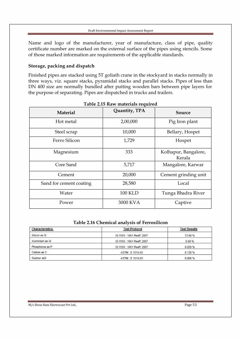
Draft Environmental Impact Assessment Report
M/s Shree Ram Electrocast Pvt Ltd., Page 53
Name and logo of the manufacturer, year of manufacture, class of pipe, qualitycertificate number are marked on the external surface of the pipes using stencils. Some of those marked information are requirements of the applicable standards.
Storage, packing and dispatch
Finished pipes are stacked using 5T goliath crane in the stockyard in stacks normally in three ways, viz. square stacks, pyramidal stacks and parallel stacks. Pipes of less than DN 400 size are normally bundled after putting wooden bars between pipe layers for the purpose of separating. Pipes are dispatched in trucks and trailers.
Table 2.15 Raw materials required
Material Quantity, TPA Source
Hot metal 2,00,000 Pig Iron plant
Steel scrap 10,000 Bellary, Hospet
Ferro Silicon 1,729 Hospet
Magnesium 333 Kolhapur, Bangalore, Kerala
Core Sand 5,717 Mangalore, Karwar
Cement 20,000 Cement grinding unit
Sand for cement coating 28,580 Local
Water 100 KLD Tunga Bhadra River
Power 3000 KVA Captive
Table 2.16 Chemical analysis of Ferrosilicon
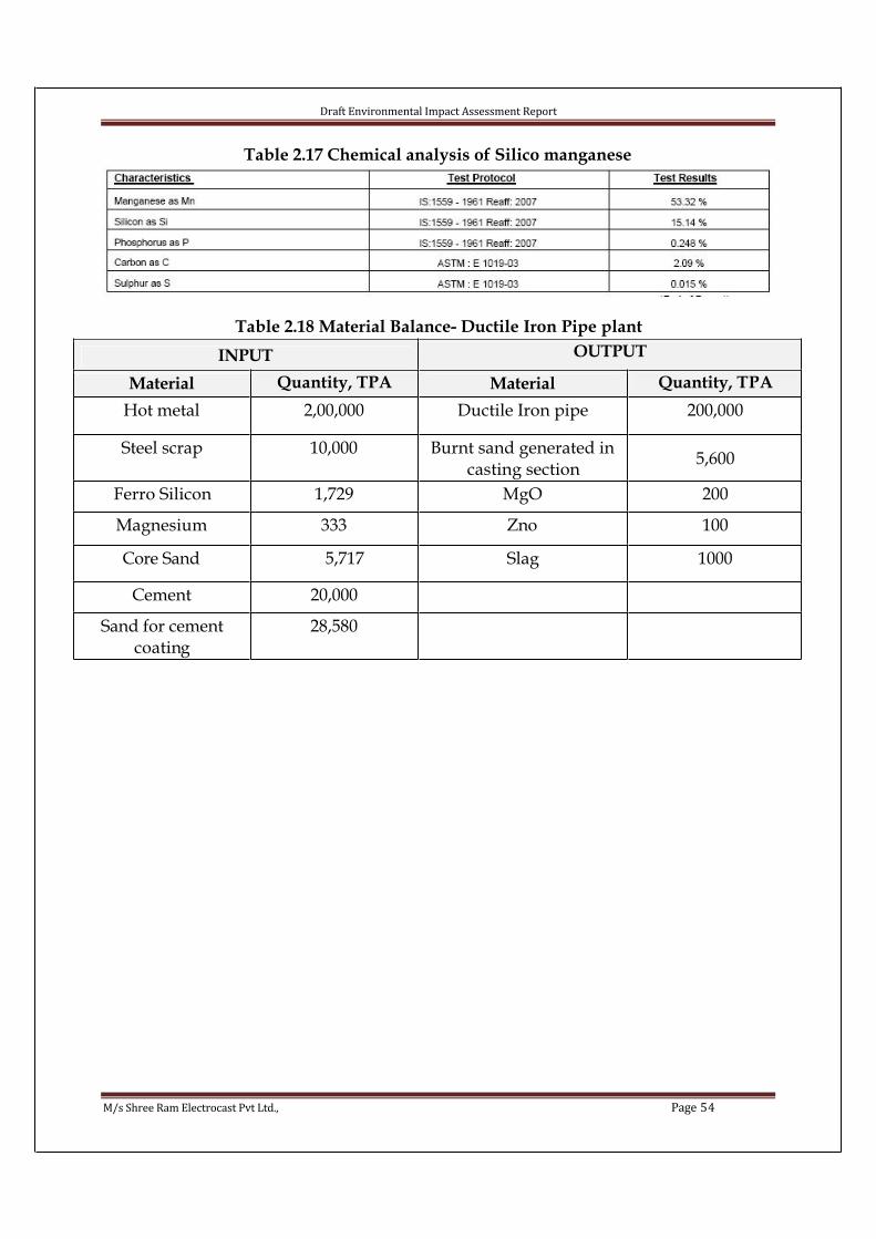
Draft Environmental Impact Assessment Report
M/s Shree Ram Electrocast Pvt Ltd., Page 54
Table 2.17 Chemical analysis of Silico manganese
Table 2.18 Material Balance- Ductile Iron Pipe plant
INPUT OUTPUT
Material Quantity, TPA Material Quantity, TPA
Hot metal 2,00,000 Ductile Iron pipe 200,000
Steel scrap 10,000 Burnt sand generated in casting section
5,600
Ferro Silicon 1,729 MgO 200
Magnesium 333 Zno 100
Core Sand 5,717 Slag 1000
Cement 20,000
Sand for cement coating
28,580

Draft Environmental Impact Assessment Report
M/s Shree Ram Electrocast Pvt Ltd., Page 55
Fig 2.11 Ductile Iron Pipe Plant- Process Flow Diagram
Hot metal
Sponge iron
Ferro alloy
CENTRIFUGAL CASTING
HOLDING FURNACE
CHARGING, ADDITIVES & SUPERHEATING
MAGNESIUM ADDITION
HEAT TREATMENT IN ANNEALING FURNACE
CUT OFF AND
CHAMFERING
INTERNAL GRINDING
BITUMEN COATING
CEMENT MORTAR LINING
& STEAM CURING
PRESSURE TESTING
STORGE, PACKING &
DESPATCH
MARKING & STENCILING
ZINC COATING
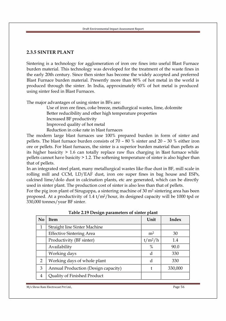
Draft Environmental Impact Assessment Report
M/s Shree Ram Electrocast Pvt Ltd., Page 56
2.3.5 SINTER PLANT
Sintering is a technology for agglomeration of iron ore fines into useful Blast Furnace burden material. This technology was developed for the treatment of the waste fines in the early 20th century. Since then sinter has become the widely accepted and preferred Blast Furnace burden material. Presently more than 80% of hot metal in the world is produced through the sinter. In India, approximately 60% of hot metal is produced using sinter feed in Blast Furnaces.
The major advantages of using sinter in BFs are: Use of iron ore fines, coke breeze, metallurgical wastes, lime, dolomite Better reducibility and other high temperature properties Increased BF productivity Improved quality of hot metal Reduction in coke rate in blast furnaces
The modern large blast furnaces use 100% prepared burden in form of sinter and pellets. The blast furnace burden consists of 70 – 80 % sinter and 20 – 30 % either iron ore or pellets. For blast furnaces, the sinter is a superior burden material than pellets as its higher basicity > 1.6 can totally replace raw flux charging in blast furnace while pellets cannot have basicity > 1.2. The softening temperature of sinter is also higher than that of pellets.In an integrated steel plant, many metallurgical wastes like flue dust in BF, mill scale in rolling mill and CCM, LD/EAF dust, iron ore super fines in bag house and ESPs,calcined lime/dolo dust in calcination plants, etc are generated, which can be directly used in sinter plant. The production cost of sinter is also less than that of pellets.For the pig iron plant of Siruguppa, a sintering machine of 30 m2 sintering area has been proposed. At a productivity of 1.4 t/m2/hour, its designed capacity will be 1000 tpd or 330,000 tonnes/year BF sinter.
Table 2.19 Design parameters of sinter plant
No Item Unit Index
1 Straight line Sinter Machine
Effective Sintering Area m2 30
Productivity (BF sinter) t/m2/h 1.4
Availability % 90.0
Working days d 330
2 Working days of whole plant d 330
3 Annual Production (Design capacity) t 330,000
4 Quality of Finished Product

Draft Environmental Impact Assessment Report
M/s Shree Ram Electrocast Pvt Ltd., Page 57
Fe (T) % 53-55
FeO % 9-12CaO % 8-10
SiO2 % 4-5
MgO % 2-3
Al2O3 % 2-3
S % 0.02-0.03
CaO/ SiO2 1.8-2.0
Granularity mm 80-6
Degradation Index for cooled sinter( -5mm) % =10
ISO Tumbler index( +6.3mm) % =66
A Sinter Plant typically comprises the sub-units as shown in figure below. The raw materials used are Iron ore fines (-10 mm), coke breeze (-3 mm), Limestone & dolomite fines (-3mm) and other metallurgical wastes such as mill scale, flue dust, etc. The proportioned raw materials are mixed and moistened in a mixing drum. The mix is loaded on sinter machine (straight line / circular) through a feeder onto a moving grate (pallet) and then the mix is rolled through segregation plate so that the coarse materials settle at the bottom and fines onto the top.The top surface of the mix is ignited through stationary burners at 12000C. As the pallet moves forward, the air is sucked through wind box situated under the grate. A high temperature combustion zone is created in the charge –bed due to combustion of solid fuel of the mix and regeneration of heat of incandescent sinter and outgoing gases. Due to forward movement of pallet, the sintering process travels vertically down.
Fig 2.12 Typical sinter plant
The hot sinter discharged from the machine is broken in a single toothed roll crusher and screened over a hot screen at a temperature of 800 – 900°C. the undersize (- 6 mm)
Proportioning
bin

Draft Environmental Impact Assessment Report
M/s Shree Ram Electrocast Pvt Ltd., Page 58
hot sinter fines are charged over the charge mix conveyor while the oversized sinter (6 –150 mm) is fed to a straight line or circular cooler where it is cooled to a temperature < 100°C.The cold sinter is screened into three fractions, 0-6 mm (cold sinter return fines), 10-20mm (hearth layer) and 6-150 mm (BF sinter). The process flow sheet of sinter plant is given below:
MATERIAL ANNUALCONSUMPTION
(TPA)
SOURCE
Iron ore fines 3,10,200 E-Auction & Pig iron plant
Lime stone 29,700 Lokapur
Dolomite 25,410 Lokapur
Quicklime 7,260 Dronachalam
Coke breeze 16,000 Coke oven plant
Mill scale 3,300 Pig iron plant
Flue dust 6,720 Pig iron plant
BF gas 1,32,00,000 m3 Pig iron plant
Water 75 KLD Tungabhadra River
Power 2000 KVA Captive
Table 2.20 Raw materials requirement

Draft Environmental Impact Assessment Report
M/s Shree Ram Electrocast Pvt Ltd., Page 59
0 - 150 mm
6 - 150 mm
Flue gas
0 – 6 mm
Hot return fi
10 - 20 mm
Hearth layer
0 - 6 mm
Cold return fi
0 - 20 mm sinter
10 - 20 mm
sinter Finished sinter to blast
furnace
Raw material proportioning system
Primary mixing drum
Secondary mixing drum
Hearth layer
hopper
Sintering machine (30
Sinter cake crushing
Hot screening
Sinter cooler, 40 m2
Primary screening
Mixture
hopper
Secondary screening
Headend ESP
Exhaust fan
Tail end ESP
Chimne
Flux fines 0-3 mm
Iron ore fines 0-8 mm
Coke fines 0-3 mm
Return fines and other materials (Mill sale & flue dust fines)
0-10 mm
water
water
20-150 mm
Exhaust fan
Chimney
Fig 2.13 Flow chart of sinter plant
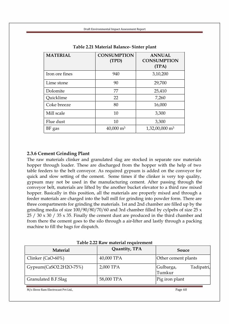
Draft Environmental Impact Assessment Report
M/s Shree Ram Electrocast Pvt Ltd., Page 60
Table 2.21 Material Balance- Sinter plant
2.3.6 Cement Grinding PlantThe raw materials clinker and granulated slag are stocked in separate raw materials hopper through loader. These are discharged from the hopper with the help of two table feeders to the belt conveyor. As required gypsum is added on the conveyor for quick and slow setting of the cement. Some times if the clinker is very top quality, gypsum may not be used in the manufacturing cement. After passing through theconveyor belt, materials are lifted by the another bucket elevator to a third raw mixed hopper. Basically in this position, all the materials are properly mixed and through a feeder materials are charged into the ball mill for grinding into powder form. There are three compartments for grinding the materials. 1st and 2nd chamber are filled up by the grinding media of size 100/90/80/70/60 and 3rd chamber filled by cylpebs of size 25 x 25 / 30 x 30 / 35 x 35. Finally the cement dust are produced in the third chamber andfrom there the cement goes to the silo through a air-lifter and lastly through a packing machine to fill the bags for dispatch.
Table 2.22 Raw material requirement
Material Quantity, TPA Souce
Clinker (CaO-60%) 40,000 TPA Other cement plants
Gypsum(CaSO2.2H2O-75%) 2,000 TPA Gulbarga, Tadipatri,Tumkur
Granulated B.F.Slag 58,000 TPA Pig iron plant
MATERIAL CONSUMPTION(TPD)
ANNUALCONSUMPTION
(TPA)
Iron ore fines 940 3,10,200
Lime stone 90 29,700
Dolomite 77 25,410
Quicklime 22 7,260
Coke breeze 80 16,000
Mill scale 10 3,300
Flue dust 10 3,300
BF gas 40,000 m3 1,32,00,000 m3

Draft Environmental Impact Assessment Report
M/s Shree Ram Electrocast Pvt Ltd., Page 61
Water 25 KLD Tungabhadra river
Power 450 KVA Captive
Table 2.23 Chemical analysis of Clinker
Table 2.24 Chemical analysis of Gypsum
Table 2.25 Chemical analysis of BF slag

Draft Environmental Impact Assessment Report
M/s Shree Ram Electrocast Pvt Ltd., Page 62
Table 2.26 Material Balance for Cement grinding plant
INPUT OUTPUT
Material Quantity, TPA Material Quantity, TPA
Clinker (CaO-60%) 40,000 TPA Cement 100,000
Gypsum(CaSO2.2H2O-75%)
2,000 TPA
Granulated B.F.Slag 58,000 TPA

Dra
ft E
nv
iro
nm
en
tal
Imp
act
Ass
ess
me
nt
Re
po
rt
M/
s S
hre
e R
am
Ele
ctro
cast
Pv
t L
td.,
Pa
ge
63
Fig
2.1
4 M
ass
Bala
nce
fo
r th
e w
ho
le p
lan
t
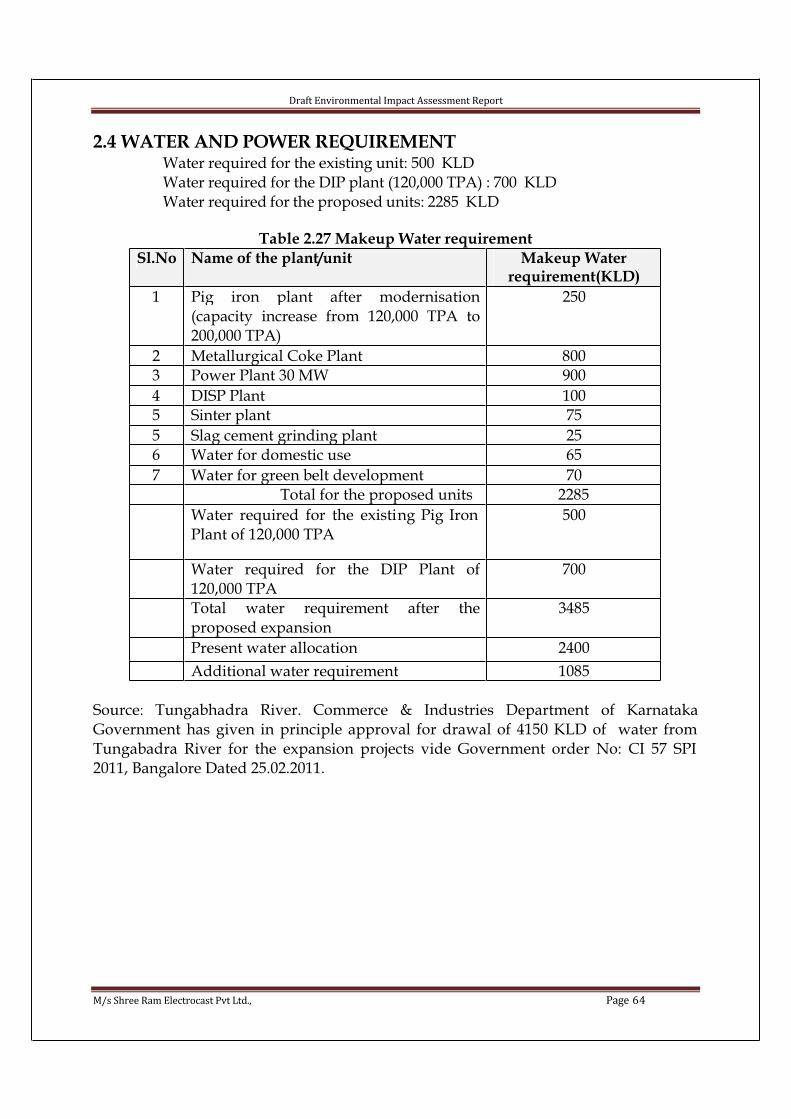
Draft Environmental Impact Assessment Report
M/s Shree Ram Electrocast Pvt Ltd., Page 64
2.4 WATER AND POWER REQUIREMENTWater required for the existing unit: 500 KLDWater required for the DIP plant (120,000 TPA) : 700 KLDWater required for the proposed units: 2285 KLD
Table 2.27 Makeup Water requirement
Sl.No Name of the plant/unit Makeup Waterrequirement(KLD)
1 Pig iron plant after modernisation(capacity increase from 120,000 TPA to200,000 TPA)
250
2 Metallurgical Coke Plant 8003 Power Plant 30 MW 900
4 DISP Plant 1005 Sinter plant 75
5 Slag cement grinding plant 256 Water for domestic use 65
7 Water for green belt development 70 Total for the proposed units 2285
Water required for the existing Pig Iron Plant of 120,000 TPA
500
Water required for the DIP Plant of120,000 TPA
700
Total water requirement after theproposed expansion
3485
Present water allocation 2400
Additional water requirement 1085
Source: Tungabhadra River. Commerce & Industries Department of KarnatakaGovernment has given in principle approval for drawal of 4150 KLD of water from Tungabadra River for the expansion projects vide Government order No: CI 57 SPI 2011, Bangalore Dated 25.02.2011.
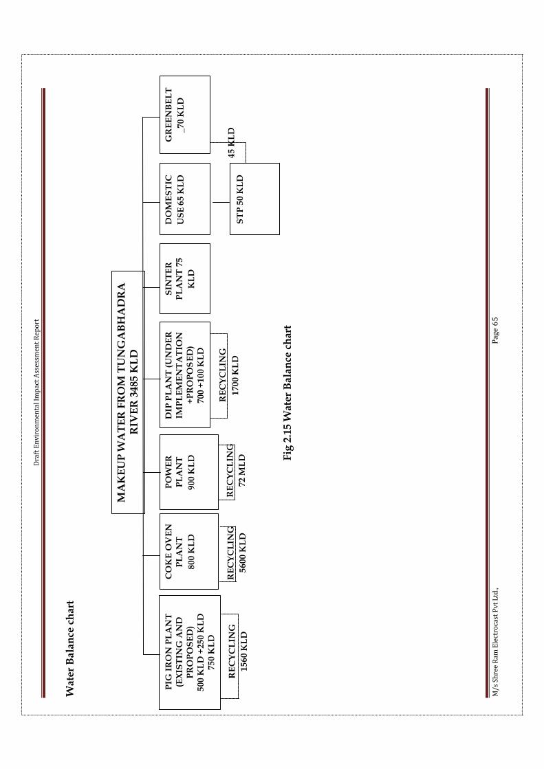
Dra
ft E
nv
iro
nm
en
tal
Imp
act
Ass
ess
me
nt
Re
po
rt
M/
s S
hre
e R
am
Ele
ctro
cast
Pv
t L
td.,
Pa
ge
65
Wat
er B
alan
ce c
har
t
Fig
2.1
5 W
ate
r B
ala
nce
ch
art
MA
KE
UP
WA
TE
R F
RO
M T
UN
GA
BH
AD
RA
R
IVE
R 3
48
5 K
LD
PIG
IR
ON
PL
AN
T
(EX
IST
ING
AN
D
PR
OP
OS
ED
)5
00
KL
D +
25
0 K
LD
75
0 K
LD
CO
KE
OV
EN
P
LA
NT
80
0 K
LD
PO
WE
RP
LA
NT
90
0 K
LD
DIP
PL
AN
T (
UN
DE
R
IMP
LE
ME
NT
AT
ION
+P
RO
PO
SE
D)
70
0 +
10
0 K
LD
SIN
TE
RP
LA
NT
75
KL
D
DO
ME
ST
IC
US
E6
5 K
LD
GR
EE
NB
EL
T
_7
0 K
LD
ST
P 5
0 K
LD
45
KL
DR
EC
YC
LIN
G
15
60
KL
D
RE
CY
CL
ING
56
00
KL
D
RE
CY
CL
ING
72
ML
D
RE
CY
CL
ING
17
00
KL
D

Draft Environmental Impact Assessment Report
M/s Shree Ram Electrocast Pvt Ltd., Page 66
Table 2.28 Power Requirement
Sl.No Name of the plant/unit Powerrequirement
(KVA)
1 Pig Iron plant-modernization to increase the capacity from 120,000TPA to 200,000TPA
1000
2 Metallurgical Coke Plant 750
3 Power plant 42004 DIP Plant 3000
5 Sinter plant 2,0005 Slag Cement Grinding plant 450
6 Utilities & auxiliaries 1,600 Total for the proposed units 13,000
Power required for the existing Pig Iron Plant of 120,000 TPA
2,000
Power required for the DIP Plant of120,000 TPA
11,000
Total Power requirement after theproposed expansion
26,000
Power available from Captive powerplants
28,900
Surplus for export 2900
The power demand will be met from the existing power plant of 2.5 MW and proposed captive power plant of 30 MW and a power grid support of 12 MVA.
Energy Balance chart

Dra
ft E
nv
iro
nm
en
tal
Imp
act
Ass
ess
me
nt
Re
po
rt
M/
s S
hre
e R
am
Ele
ctro
cast
Pv
t L
td.,
Pa
ge
67
Fig
2.1
6 E
ne
rgy
Ba
lan
ce c
ha
rt
PIG
IR
ON
PL
AN
T
(EX
IST
ING
AN
D
PR
OP
OS
ED
)3
00
0 K
VA
CO
KE
OV
EN
P
LA
NT
75
0 K
VA
DIP
PL
AN
T (
UN
DE
R
IMP
LE
ME
NT
AT
ION
+P
RO
PO
SE
D)
11
00
0 +
30
00
KV
A
SIN
TE
RP
LA
NT
20
00
KV
A
EX
PO
RT
TO
G
RID
29
00
KV
A
UT
ILIT
IES
AN
D
AU
XIL
LE
RIE
S,
16
00
KV
A
CE
ME
NT
PL
AN
T
45
0 K
VA
CA
PT
IVE
PO
WE
R P
LA
NT
30
MW
+E
XIS
TIN
G 2
.5 M
WP
LD
- 80%
, P
F 0
.9,
28.9
MV
A,
PO
WE
R P
LA
NT
CO
NS
UM
PT
ION
:4.2
VA
,
NE
T P
OW
ER
AV
AIL
AB
LE
: 24.7
MV
A
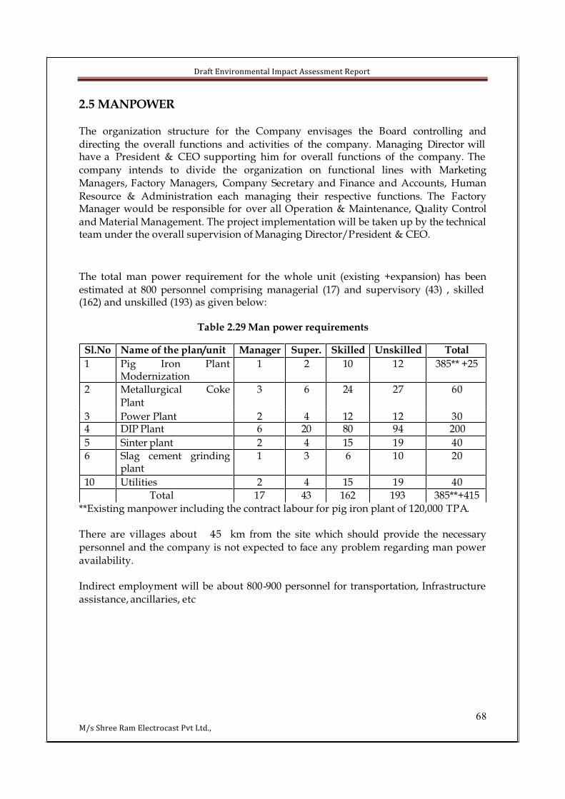
Draft Environmental Impact Assessment Report
68M/s Shree Ram Electrocast Pvt Ltd.,
2.5 MANPOWER
The organization structure for the Company envisages the Board controlling and
directing the overall functions and activities of the company. Managing Director will have a President & CEO supporting him for overall functions of the company. The
company intends to divide the organization on functional lines with Marketing
Managers, Factory Managers, Company Secretary and Finance and Accounts, Human
Resource & Administration each managing their respective functions. The FactoryManager would be responsible for over all Operation & Maintenance, Quality Control
and Material Management. The project implementation will be taken up by the technical team under the overall supervision of Managing Director/President & CEO.
The total man power requirement for the whole unit (existing +expansion) has been
estimated at 800 personnel comprising managerial (17) and supervisory (43) , skilled (162) and unskilled (193) as given below:
Table 2.29 Man power requirements
**Existing manpower including the contract labour for pig iron plant of 120,000 TPA.
There are villages about 4-5 km from the site which should provide the necessary
personnel and the company is not expected to face any problem regarding man power
availability.
Indirect employment will be about 800-900 personnel for transportation, Infrastructure
assistance, ancillaries, etc
Sl.No Name of the plan/unit Manager Super. Skilled Unskilled Total
1 Pig Iron PlantModernization
1 2 10 12 385** +25
2 Metallurgical Coke
Plant
3 6 24 27 60
3 Power Plant 2 4 12 12 304 DIP Plant 6 20 80 94 200
5 Sinter plant 2 4 15 19 40
6 Slag cement grindingplant
1 3 6 10 20
10 Utilities 2 4 15 19 40
Total 17 43 162 193 385**+415
Draft Environmental Impact Assessment Report
69M/s Shree Ram Electrocast Pvt Ltd.,
CHAPTER III- DESCRIPTION OF THE ENVIRONMENT
3.0 IntroductionThe proposed project is an expansion project with the following units:
• Pig iron plant modernization to improve the fuel efficiency and increase
in production capacity from 120,000 TPA to 2,00,000TPA
• Coke Oven Plant - 160,000 TPA
• Captive Power Plant - 30 MW
• Expansion of Ductile Iron Pipe Plant- from 1,20,000 TPA to 200,000 TPA
• Sinter Plant – 300,000 TPA
• Cement Grinding Plant – 100,000 TPA
at Sy.No.s 80, 81/A3, 95/A1, 95/A3, 96/A1, 96/A3, 97/1, 97/3, 98/A/1A, 98/A/1B,
98/A3, 98/B1, 98/B3, 98/C1,98/C3, 98/D1, 98/D3, 99, 100, 103, 104, 105 and 106 ofHonnarahalli Village and Sy, No. 57/C/1, 57/D/1, 57/A/1A, 57/A/2A, 57/A/3A, 57/B/A, 57/A/4A, 77/A, 77/B, 78/A and 78/B of Halkote Village, Post – Hatcholi,
Taluk- Siruguppa, Dist.- Bellary, Karnataka. Tunga Bhadra River is located at a distance
of 1.8 Kms from the proposed project site and villages like Honnarahalli village,
Hachcholli village, Chickabellary at a distance of around 2-5 kms from the proposed expansion project site. Siruguppa is at a distance of 13.5 Kms from the proposed
expansion project site. Hachcholli - Siruguppa road is adjacent to the project site in the
Eastern Direction.
The plant is located at 66.6 kms from Bellary town, which is proximate to rich deposits
of Iron ore at Bellary, Hospet & Sandur area to provide an assured and continuous
supply of raw materials. Well known fact that Karnataka is the richest in terms of mineral potential in the country, with large deposit of Iron ore. Considering the demand for steel and steel
products, the company proposes to utilise the opportunity and therefore has proposed
to set up the above mentioned units at the existing pig iron plant.
The location is very well connected by Road & Rail. Moreover, the unit will further add
to the Economy of the state and provide additional employment to the people of
neighbouring villages.
This Environmental Impact Assessment Study report will give an assessment of the
various environmental impacts likely to be caused on the surrounding nature in and
around the proposed project. It will also incorporate the appropriate control measures
required to be adopted or implemented in order to minimize the adverse effects thereof. In order to carry out such assessment study, it is first necessary to delineate and define
the existing environmental factors in and around the proposed project on the existing
environmental scenario which will include various environs like ecology, Flora-fauna,
socio economic profiles, environmental quality in respect of air, water, noise & soil etc. This section incorporates the description of the existing environmental settings within
the area encompassed by a circle of 10 km radius around the proposed project site.

Draft Environmental Impact Assessment Report
70M/s Shree Ram Electrocast Pvt Ltd.,
The base line study was conducted during the month of October 2011 to December2011.
3.1 Baseline Data • Primary data collected for various environmental aspects
Table 3.1 Primary data collected
Parameter Locations for proposed
data collection
Source
Air Quality 8 locations Primary
Water 9 locations Primary
Meteorology 1 location PrimarySoil 5 locations Primary and Secondary
Noise Level 6 locations Primary
Ecology Study Area Primary and Secondary
Geology and Hydrology Study Area Primary and SecondaryLand use Study area Primary and secondary
Socio-Economic Study Area Secondary
• Secondary data will be collected from published sources and Government
agencies
3.2 Soil Characteristics
The proposed project site has red soil mixed loamy soil and also having partly red sandy
suitable for agriculture and horticulture crops. The taluk is having few RockyMountains with exrophytic vegetation. The soil samples collected from the proposed project site and within the study area too
were analyzed for important parameters and the results of the soil quality are tabulated
below.

Draft Environmental Impact Assessment Report
71M/s Shree Ram Electrocast Pvt Ltd.,
Fig 3.1 Location of Soil sampling stationsTable 3.2 Location of soil sampling stations
Sample Location Distance
S1 Project Site -
S2 Shridaragadde 2.0
S3 Road going towards Honnarhalli 1.5
S4 Chikka Bellary 3.0
S5 Walabalary 3.5
S2
S3
S5S4
S1
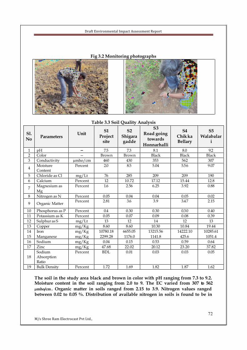
Draft Environmental Impact Assessment Report
72M/s Shree Ram Electrocast Pvt Ltd.,
Fig 3.2 Monitoring photographs
Table 3.3 Soil Quality Analysis
Sl.No
ParametersUnit
S1Project
site
S2Shigaragadde
S3Road going
towards
Honnarhalli
S4ChikkaBellary
S5Walabalar
i
1 pH -- 7.5 7.3 8.1 8.0 9.22 Color -- Brown Brown Black Black Black
3 Conductivity µmho/cm 460 430 353 562 307
4MoistureContent
Percent 2.0 8.5 5.04 5.56 9.07
5 Chloride as Cl mg/Lt 76 285 209 209 190
6 Calcium Percent 12 10.72 17.12 15.44 12.8
7Magnesium as
Mg
Percent 1.6 2.56 6.25 3.92 0.88
8 Nitrogen as N Percent 0.05 0.04 0.04 0.05 0.02
9 Organic MatterPercent 2.81 3.6 3.9 3.47 2.15
10 Phosphorus as P Percent 0.4 0.30 0.30 0.30 0.40
11 Potassium as K Percent 0.05 0.07 0.09 0.08 0.39
12 Sulphur as S mg/Lt 13 12 14 12 13
13 Copper mg/Kg 8.60 8.60 10.30 10.84 19.44
14 Iron mg/Kg 10780.18 6655.05 13215.56 14222.10 10285.61
15 Manganese mg/Kg 2299.28 1176.0 1141.8 425.6 1051.4
16 Sodium mg/Kg 0.04 0.15 0.53 0.59 0.64
17 Zinc mg/Kg 47.68 22.02 20.12 23.20 37.82
18SodiumAbsorptionRatio
Percent BDL 0.01 0.03 0.03 0.05
19 Bulk Density Percent 1.72 1.69 1.82 1.87 1.62
The soil in the study area black and brown in color with pH ranging from 7.3 to 9.2.Moisture content in the soil ranging from 2.0 to 9. The EC varied from 307 to 562
µmho/cm. Organic matter in soils ranged from 2.15 to 3.9. Nitrogen values ranged between 0.02 to 0.05 %. Distribution of available nitrogen in soils is found to be in

Draft Environmental Impact Assessment Report
73M/s Shree Ram Electrocast Pvt Ltd.,
sufficient levels. The Phosphorus levels ranged between 0.3 to 0.4 %. Soil potassiumvaried from 0.05-0.39%.
3.3 Air EnvironmentDispersion of different air pollutants released into the atmosphere have significant
impacts on the neighbourhood air environment of an industrial project and forms an
important part of impact assessment studies. The ambient air quality status with respect
to the study zone of 10 km radial distance from the plant site will form the base line information over which the predicted impacts due to the proposed expansion plant can
be super imposed to find out the net (Final) impacts on air environment. From the final
impacts a viable Environmental Management Plan (EMP) can be prepared based on the impact statement for the air environment. The baseline status of the ambient air quality can be assessed thorough scientifically designed ambient air quality monitoring
network. The design of monitoring network in the air quality surveillance program has
to be based on the following considerations.
• Meteorological conditions on synoptic scale
• Topography of the study area
• Representation of regional background levels
• Representation of plant site
• Representation of cross sectional distribution in the downward direction
• Influence of the existing sources if any, are to be kept at minimum
• Inclusion of major distinct villages to collect the baseline status
3.3.1 Micrometeorological Data
Micro-meteorological data within the project area during the air quality survey period is
an indispensable part of air pollution study. The meteorological data recorded during survey period is very useful for proper interpretation of the baseline information as well
as for input, to predictive models for air quality impacts.
To understand meteorological scenario primary and secondary data collected and used in the interpretation of the data and data collected from the both sources are
summarized as followsTable 3.4 Data collection for Meteorological data
Meteorological
data
Primary data: Hourly data of site
Wind speed, Direction, Temperature, RH, station level pressure & rainfall
(Daily maximum, minimum, highest, lowest temperatures,
maximum, minimum humidity, Rainfall and mean wind speed
mean monthly wise data)
3.3.1.1 Historical Data
Historical data on meteorological parameters also plays an important role in identifying
the general meteorological status of the region. The data generated in the field iscompared with the historical data.
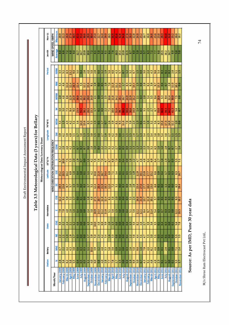
Dra
ft E
nv
iro
nm
en
tal
Imp
act
Ass
ess
me
nt
Re
po
rt
74
M/
s S
hre
e R
am
Ele
ctro
cast
Pv
t L
td.,
Tab
le 3
.5 M
ete
oro
log
ical
Data
(3
ye
ars
) fo
r B
ell
ary
So
urc
e: A
s p
er
IMD
, P
un
e 3
0 y
ea
r d
ata
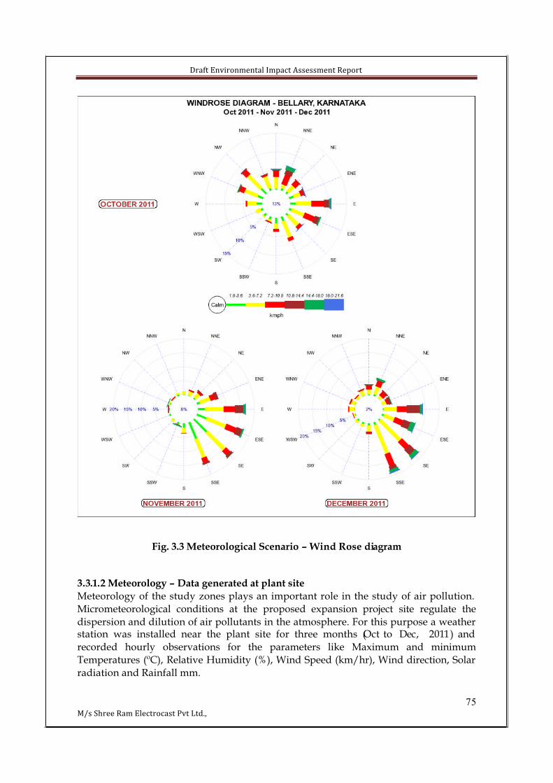
Draft Environmental Impact Assessment Report
75M/s Shree Ram Electrocast Pvt Ltd.,
Fig. 3.3 Meteorological Scenario – Wind Rose diagram
3.3.1.2 Meteorology – Data generated at plant site
Meteorology of the study zones plays an important role in the study of air pollution.
Micrometeorological conditions at the proposed expansion project site regulate the
dispersion and dilution of air pollutants in the atmosphere. For this purpose a weather station was installed near the plant site for three months (Oct to Dec, 2011) and
recorded hourly observations for the parameters like Maximum and minimum
Temperatures (ºC), Relative Humidity (%), Wind Speed (km/hr), Wind direction, Solar
radiation and Rainfall mm.

Draft Environmental Impact Assessment Report
76M/s Shree Ram Electrocast Pvt Ltd.,
The hourly-recorded observations (wind velocity and wind directions) during 12 weeks
study period are used in computing percentage frequencies (0-7 morning, 8-15 noon,
14-24 evening & 0-24 hrs) and are depicted in the form of ‘wind roses’.Table 3.6 meterological data for the period Oct-Dec 2011
WindDirection,
°from North
WindSpeed,kmph
Temperature,°C
RelativeHumidity,
%
StationLevel
Pressure
in hPa
Rainfall,mm
OctoberMax 360 20.8 33.7 100 964 6
Min 9.1 0.2 20.9 37 956 0
Avg 170 5.8 26.5 81.0 960.2 0.02
November
Max 360 18.2 32.8 95 967 1.5Min 10 0.2 16.1 27 957 0
Avg 127.7 5.7 23.8 70.4 962.0 0.007
December
Max 360 27 31.9 100 967 10
Min 10 1 12.6 20 957 0Avg 139.3 7.7 22.9 71.3 962.1 0.02
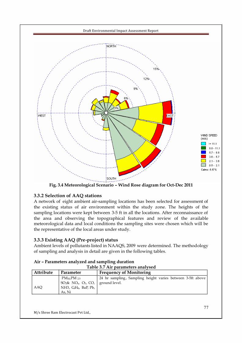
Draft Environmental Impact Assessment Report
77M/s Shree Ram Electrocast Pvt Ltd.,
Fig. 3.4 Meteorological Scenario – Wind Rose diagram for Oct-Dec 2011
3.3.2 Selection of AAQ stationsA network of eight ambient air-sampling locations has been selected for assessment of
the existing status of air environment within the study zone. The heights of the
sampling locations were kept between 3-5 ft in all the locations. After reconnaissance of
the area and observing the topographical features and review of the availablemeteorological data and local conditions the sampling sites were chosen which will be
the representative of the local areas under study.
3.3.3 Existing AAQ (Pre-project) statusAmbient levels of pollutants listed in NAAQS, 2009 were determined. The methodology
of sampling and analysis in detail are given in the following tables.
Air – Parameters analyzed and sampling durationTable 3.7 Air parameters analysed
Attribute Parameter Frequency of Monitoring
AAQ
PM10,PM 2.5
SO2& NOx, O3, CO,
NH3, C6H6, BaP, Pb, As, Ni
24 hr sampling , Sampling height varies between 3-5ft above
ground level.
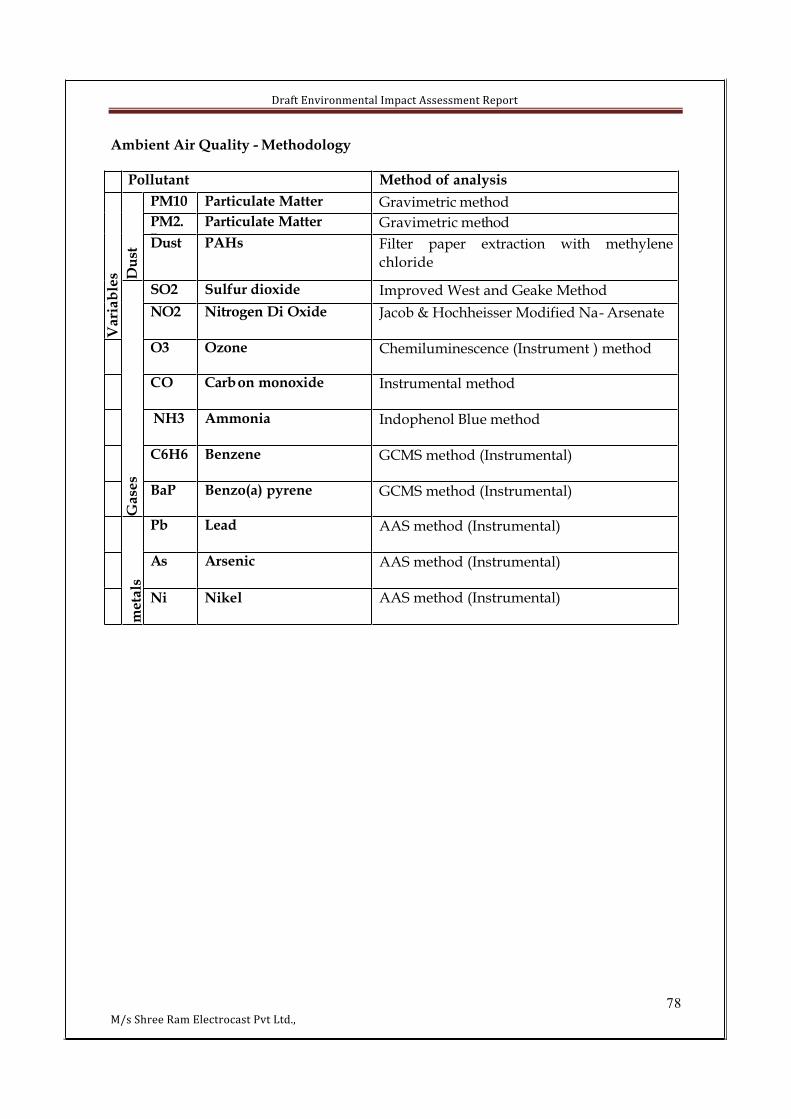
Draft Environmental Impact Assessment Report
78M/s Shree Ram Electrocast Pvt Ltd.,
Ambient Air Quality - Methodology
Pollutant Method of analysis
PM10 Particulate Matter Gravimetric method
PM2.5
Particulate Matter Gravimetric method
Du
st
Dust PAHs Filter paper extraction with methylene
chloride
SO2 Sulfur dioxide Improved West and Geake Method
Va
ria
ble
s
NO2 Nitrogen Di Oxide Jacob & Hochheisser Modified Na- Arsenate
O3 Ozone Chemiluminescence (Instrument ) method
CO Carbon monoxide Instrumental method
NH3 Ammonia Indophenol Blue method
C6H6 Benzene GCMS method (Instrumental)
Ga
ses
BaP Benzo(a) pyrene GCMS method (Instrumental)
Pb Lead AAS method (Instrumental)
As Arsenic AAS method (Instrumental)
meta
ls
Ni Nikel AAS method (Instrumental)
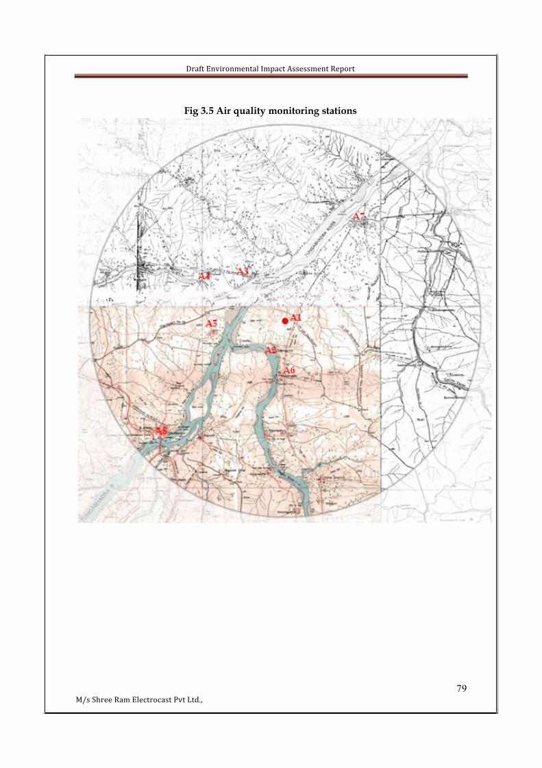
Draft Environmental Impact Assessment Report
79M/s Shree Ram Electrocast Pvt Ltd.,
Fig 3.5 Air quality monitoring stations
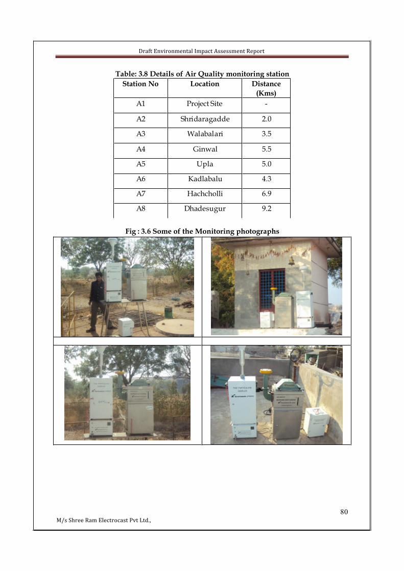
Draft Environmental Impact Assessment Report
80M/s Shree Ram Electrocast Pvt Ltd.,
Table: 3.8 Details of Air Quality monitoring station
Station No Location Distance
(Kms)
A1 Project Site -
A2 Shridaragadde 2.0
A3 Walabalari 3.5
A4 Ginwal 5.5
A5 Upla 5.0
A6 Kadlabalu 4.3
A7 Hachcholli 6.9
A8 Dhadesugur 9.2
Fig : 3.6 Some of the Monitoring photographs
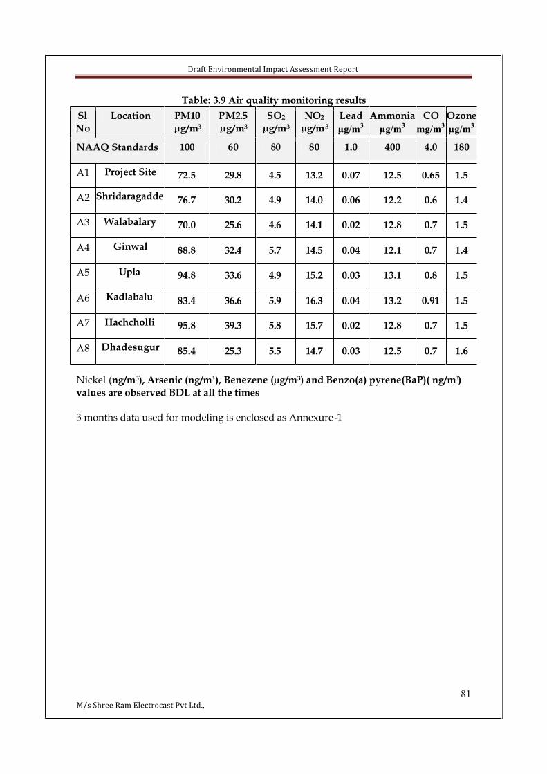
Draft Environmental Impact Assessment Report
81M/s Shree Ram Electrocast Pvt Ltd.,
Table: 3.9 Air quality monitoring results
Sl
No
Location PM10
µg/m3
PM2.5
µg/m3
SO2
µg/m3
NO2
µg/m3
Lead
µg/m3
Ammonia
µg/m3
CO
mg/m3
Ozone
µg/m3
NAAQ Standards 100 60 80 80 1.0 400 4.0 180
A1 Project Site 72.5 29.8 4.5 13.2 0.07 12.5 0.65 1.5
A2 Shridaragadde 76.7 30.2 4.9 14.0 0.06 12.2 0.6 1.4
A3 Walabalary 70.0 25.6 4.6 14.1 0.02 12.8 0.7 1.5
A4 Ginwal 88.8 32.4 5.7 14.5 0.04 12.1 0.7 1.4
A5 Upla 94.8 33.6 4.9 15.2 0.03 13.1 0.8 1.5
A6 Kadlabalu 83.4 36.6 5.9 16.3 0.04 13.2 0.91 1.5
A7 Hachcholli 95.8 39.3 5.8 15.7 0.02 12.8 0.7 1.5
A8 Dhadesugur 85.4 25.3 5.5 14.7 0.03 12.5 0.7 1.6
Nickel (ng/m3), Arsenic (ng/m3), Benezene (µg/m3) and Benzo(a) pyrene(BaP)( ng/m3)
values are observed BDL at all the times
3 months data used for modeling is enclosed as Annexure -1

Dra
ft E
nv
iro
nm
en
tal
Imp
act
Ass
ess
me
nt
Re
po
rt
82
M/
s S
hre
e R
am
Ele
ctro
cast
Pv
t L
td.,
Tab
le 3
.10
Co
nce
ntr
atio
n o
f P
M10
Ta
ble
3.1
1 C
on
cen
tra
tio
n o
f P
M2
.5
Tab
le 3
.12
Co
nce
ntr
ati
on
of
SO
2
LO
CA
TIO
NM
AX
MIN
AV
GS
DG
M98
PE
RC
EN
TIL
E85
PE
RC
EN
TIL
E50
PE
RC
EN
TIL
E35
PE
RC
EN
TIL
E
Pro
ject
sit
e –
A1
78
687
2.5
2.8
72
.47
7.5
75
.57
2.5
71.0
Hac
ho
lli-
A2
86
707
6.7
4.3
76
.68
5.5
48
0.5
76
.57
5
Sh
irag
ad
de
-A3
78
566
6.0
7.7
65.
47
7.5
47
6.5
626
1
Near
Ku
dad
ala
hall
i-
A4
78
707
4.5
2.1
74
.578
7774
74
Nea
r G
inw
al-A
57
969
743
.27
3.9
78.
54
7873
72
Ne
ar
Wa
lba
lari
-A6
79
607
1.5
5.5
71
.57
8.5
47
6.5
73
.570
.1
Ne
ar
Up
la-A
77
970
74
.53
.17
4.5
7978
757
4
Near
Dh
od
esu
gar-
A8
79
707
4.5
2.6
74
.47
8.5
477
74
.573
.05
LO
CA
TIO
NM
AX
MIN
AV
GS
DG
M98
PE
RC
EN
TIL
E85
PE
RC
EN
TIL
E50
PE
RC
EN
TIL
E35
PE
RC
EN
TIL
EP
roje
ct s
ite
–A
139
2129
.84
.72
9.4
37
.63
4.5
30
28
Hach
oll
i- A
239
1830
.25
.72
9.6
38
.54
35
.53
22
9.0
5
Sh
irag
ad
de
-A3
3817
25.6
6.1
24
.93
7.0
83
32
42
2.0
Nea
r K
ud
adal
ahal
li-
A4
3826
32.4
3.4
32
.238
36
33
30
.05
Ne
ar
Gin
wa
l-A
552
1833
.61
1.7
31
.65
1.5
49
.13
32
8.1
Ne
ar
Wa
lba
lari
-A6
4526
36.6
5.9
36
.14
4.5
42
.53
83
3.1
Nea
r U
pla
-A7
6126
39.3
11
.03
8.0
60
.55
5.1
34
33
Ne
ar
Dh
od
esu
ga
r-A
833
1925
.33
.62
5.0
31
.62
92
5.5
24
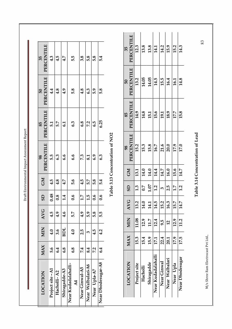
Dra
ft E
nv
iro
nm
en
tal
Imp
act
Ass
ess
me
nt
Re
po
rt
83
M/
s S
hre
e R
am
Ele
ctro
cast
Pv
t L
td.,
Ta
ble
3.1
3 C
on
cen
tra
tio
n o
f N
O2
Tab
le 3
.14
Co
nce
ntr
ati
on
of
Le
ad
LO
CA
TIO
NM
AX
MIN
AV
GS
DG
M98
PE
RC
EN
TIL
E85
PE
RC
EN
TIL
E50
PE
RC
EN
TIL
E35
PE
RC
EN
TIL
E
Pro
ject
sit
e –
A1
5.6
4.0
4.5
0.4
84.
55
.55
.14
.44.
3
Hac
ho
lli-
A2
6.4
3.6
4.9
0.8
4.8
6.3
5.7
4.8
4.5
Sh
ira
ga
dd
e-A
36.
8B
DL
4.6
1.4
4.7
6.6
6.1
4.9
4.7
Near
Ku
dad
ala
hall
i-
A4
6.8
4.0
5.7
0.6
5.6
6.6
6.3
5.8
5.5
Ne
ar
Gin
wa
l-A
57.
42
.54
.91
.74.
57
.36
.84
.83.
8
Ne
ar
Wa
lba
lari
-A6
8.4
35
.91
.55.
78
.17
.26
.35.
8
Nea
r U
pla
-A7
7.2
4.5
5.8
0.6
5.8
6.9
6.5
5.9
5.8
Ne
ar
Dh
od
esu
gar
-A8
6.4
4.2
5.5
0.6
5.4
6.3
6.2
55
.85.
4
LO
CA
TIO
NM
AX
MIN
AV
GS
DG
M98
PE
RC
EN
TIL
E85
PE
RC
EN
TIL
E50
PE
RC
EN
TIL
E35
PE
RC
EN
TIL
E
Pro
ject
sit
e1
5.3
11.0
81
3.2
1.3
13
.11
5.2
14.9
13
.21
2.3
Hac
ho
lli
15
.41
2.9
14
.00
.71
4.0
15
.314
.814
.05
13
.8
Sh
ira
ga
dd
e1
5.9
11
.71
4.1
1.0
71
4.0
15
.815
.114
.05
13
.8
Near
Ku
dad
ala
hall
i1
7.1
12
.41
4.5
1.2
14
.41
6.7
15.6
14
.51
4.1
Near
Gin
wal
22
.49
.51
5.2
31
4.7
21
.619
.11
5.5
14
.2
Ne
ar
Wa
lba
lari
20
.112
16
.32
.51
6.0
20
.018
.91
6.4
15
.9
Nea
r U
pla
17
.91
2.9
15
.71
.71
5.6
17
.917
.71
6.1
15
.2
Nea
r D
ho
des
ug
ar1
7.5
11
.21
4.7
1.2
14
.71
7.0
15.8
14
.81
4.3

Dra
ft E
nv
iro
nm
en
tal
Imp
act
Ass
ess
me
nt
Re
po
rt
84
M/
s S
hre
e R
am
Ele
ctro
cast
Pv
t L
td.,
Ta
ble
3.1
5 C
on
cen
trat
ion
of
Am
mo
nia
LO
CA
TIO
NM
AX
MIN
AV
GS
DG
M98
PE
RC
EN
TIL
E85
PE
RC
EN
TIL
E50
PE
RC
EN
TIL
E35
PE
RC
EN
TIL
E
Pro
ject
sit
e –
A1
0.51
0.0
10
.07
0.0
10.
040
.40
.08
0.4
0.03
Hac
ho
lli-
A2
0.48
0.0
10
.06
0.0
10.
040.
360
.08
0.4
0.03
Sh
ira
ga
dd
e-A
30.
08B
DL
0.0
20
.02
0.02
0.07
0.0
50
.03
0.02
Near
Ku
dad
ala
hall
i-
A4
0.2
0.0
10
.04
0.0
30.
030
.10
.06
0.0
40.
03
Ne
ar
Gin
wa
l-A
50.
240
.00
80
.03
0.0
50.
020
.10
.04
0.0
30.
02
Ne
ar
Wa
lba
lari
-A6
0.1
0.0
08
0.0
40
.02
0.03
0.08
0.0
60
.03
0.03
Nea
r U
pla
-A7
0.05
0.0
10
.02
0.0
10.
020.
040
.04
0.0
20.
02
Near
Dh
od
esu
gar-
A8
0.06
0.0
10
.03
0.0
10.
030.
050
.04
0.0
40.
03
LO
CA
TIO
NM
AX
MIN
AV
GS
DG
M98
PE
RC
EN
TIL
E85
PE
RC
EN
TIL
E50
PE
RC
EN
TIL
E35
PE
RC
EN
TIL
E
Pro
ject
sit
e –
A1
14
.21
0.8
12
.50
.81
2.5
13
.913
.21
2.7
12
.3
Hac
ho
lli-
A2
14
.11
0.5
12
.20
.91
2.2
13
.813
.11
2.4
11
.8
Sh
ira
ga
dd
e-A
31
4.2
11
.41
2.8
0.7
12
.81
4.1
13.6
12
.91
2.5
Nea
r K
ud
adal
ahal
li-
A4
141
10
.61
2.1
0.7
12
.11
3.7
13.0
11
.91
1.9
Nea
r G
inw
al-A
51
5.8
10
.41
3.1
1.4
13
.01
5.4
14.5
13.0
51
2.6
Nea
r W
alb
alar
i-A
61
6.1
9.8
13
.21
.81
3.0
15
.915
.41
3.1
12
.1
Ne
ar
Up
la-A
71
4.8
9.6
12
.81
.41
2.7
14
.714
.11
3.2
12
.8
Near
Dh
od
esu
gar-
A8
15
.61
0.4
12
.51
.51
2.4
15
.414
.11
2.4
11
.8

Dra
ft E
nv
iro
nm
en
tal
Imp
act
Ass
ess
me
nt
Re
po
rt
85
M/
s S
hre
e R
am
Ele
ctro
cast
Pv
t L
td.,
Ta
ble
3.1
6 C
on
cen
tra
tio
n o
f C
O
Tab
le 3
.17 C
on
cen
trati
on
of
Ozo
ne
LO
CA
TIO
NM
AX
MIN
AV
GS
DG
M98
PE
RC
EN
TIL
E85
PE
RC
EN
TIL
E50
PE
RC
EN
TIL
E35
PE
RC
EN
TIL
E
Pro
ject
sit
e –
A1
1.8
1.1
1.5
0.2
1.4
1.8
1.7
1.5
1.4
Hac
ho
lli-
A2
1.9
0.6
1.4
0.2
1.4
1.9
1.7
1.5
1.4
Sh
ira
ga
dd
e-A
32
.11
.11
.50
.21
.41.
91
.71
.51.
4
Nea
r K
ud
adal
ahal
li-
A4
1.8
1.1
1.4
0.2
1.4
1.8
1.7
1.5
1.4
Nea
r G
inw
al-A
52
.11
.21
.50
.23
1.5
2.0
1.7
1.5
1.4
Nea
r W
alb
alar
i-A
62
.41
.11
.50
.31
.52.
21
.81
.51.
4
Ne
ar
Up
la-A
71
.91
.21
.50
.19
1.4
1.8
51
.71
.51.
4
Near
Dh
od
esu
gar-
A8
2.6
1.2
1.6
0.2
1.5
2.2
1.8
1.6
1.5
LO
CA
TIO
NM
AX
MIN
AV
GS
DG
M98
PE
RC
EN
TIL
E85
PE
RC
EN
TIL
E50
PE
RC
EN
TIL
E35
PE
RC
EN
TIL
E
Pro
ject
sit
e –
A1
1.1
0.3
0.6
50
.20
.61.
00
.80
.60.
6
Hac
ho
lli-
A2
1.1
0.3
0.6
0.1
0.6
1.0
0.8
0.7
0.6
Sh
ira
ga
dd
e-A
31
.20
.30
.70
.20
.71.
10.
950
.75
0.7
Nea
r K
ud
adal
ahal
li-
A4
1.2
0.3
0.7
0.2
0.7
1.2
1.1
0.7
50.
7
Nea
r G
inw
al-A
51
.30
.50
.80
.20
.81.
21
.00
.80.
7
Nea
r W
alb
alar
i-A
61
.30
.50
.91
0.2
0.8
1.3
1.5
0.9
0.8
Ne
ar
Up
la-A
71
.10
.40
.70.
10
.61
.05
0.9
0.7
0.7
Near
Dh
od
esu
gar-
A8
1.2
0.3
0.7
0.2
0.7
1.1
1.0
0.8
0.7

Draft Environmental Impact Assessment Report
86M/s Shree Ram Electrocast Pvt Ltd.,
3.4 NOISE ENVIRONMENT
The word noise arose from the Latin word ‘nauseas’, it is a loud outcry or commotion that is unpleasant, unexpected, or undesired with various frequencies over the audible
range due to the regular activities of the Mankind primarily Noise pollution (or
environmental noise) is displeasing human, animal or machine-created sound thatdisrupts the activity or balance of humans or animals life. The source of most outdoor noise worldwide is mainly evolved from Industries, constructions and transportation
systems, including motor vehicle noise, aircraft noise and rail noise, poor urban
planning may give rise to noise pollution
Industrial Noise resulting to noise pollution has many reasons such as industries being
close to human habitats which prevent the noise from decaying before it reaches human
ear.
A determination is made of the micro scale impact by predicting anticipated noise levels for each alternative during both construction and operational phases. Predicted noise
levels are compared with applicable standards or criteria in order to assess the impact.
The physical description of sound concerns its loudness as a function of frequency.
Noise in general sound which comprises of many frequency components with different variations in loudness over the audible frequency range.
Various noise scales have been introduced to describe, a single number, the response of
an average human to a complex sound made up of various frequencies at different loud levels, the response of the human ear to sound is dependent on the frequency of the sound and this has led to the concept of weighting scales. In the "A -weighting" scale, the
sound pressure levels for the lower frequencies and higher frequencies are reduced by
certain amounts before they are being combined together to give one single sound
pressure level value. This value is designated as dB (A). The dB (A) is often used as it reflects more accurately the frequency response of the human ear. A perceived loud
noise has a high dB or dB (A) value and a soft noise has a low one. The human ear has
peak response around 2,500 to 3,000 Hz and has a relatively low response at low
frequencies
3.4.1 Impact Assessment of Noise Environment
The environmental impact assessment of noise for the proposed project was carried out
by taking various factors into consideration like potential physiological responses,annoyance and general community responses and also taking all the factors mentioned
in the above lines in to considerations the existing status of noise levels within the Study
zone, which is a primary requirement for impact assessment studies has been
undertaken for the monitoring of baseline noise levels.
3.4.2 Existing Noise Levels
Existing pre -project noise levels have been monitored at different points within the
study zone. Keeping in view of various local activities such as residential, commercial
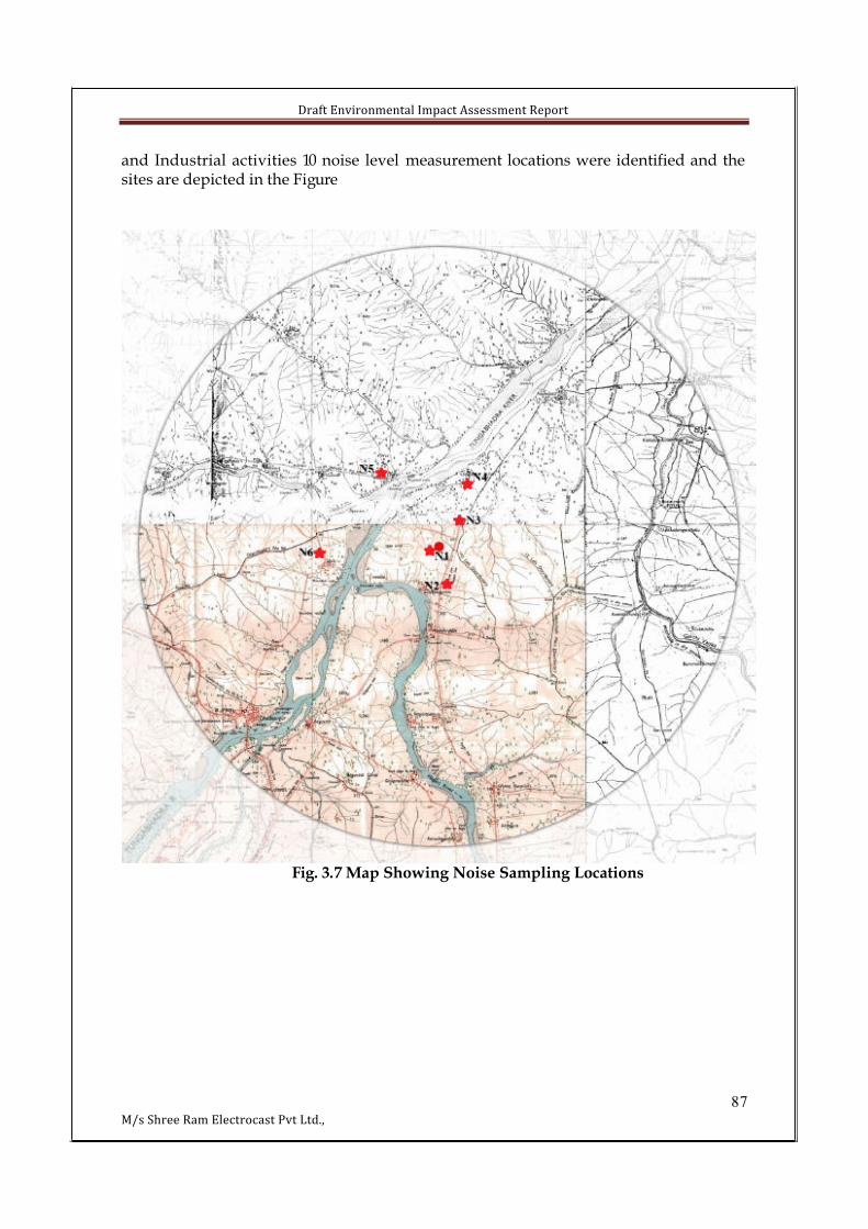
Draft Environmental Impact Assessment Report
87M/s Shree Ram Electrocast Pvt Ltd.,
and Industrial activities 10 noise level measurement locations were identified and the sites are depicted in the Figure
Fig. 3.7 Map Showing Noise Sampling Locations
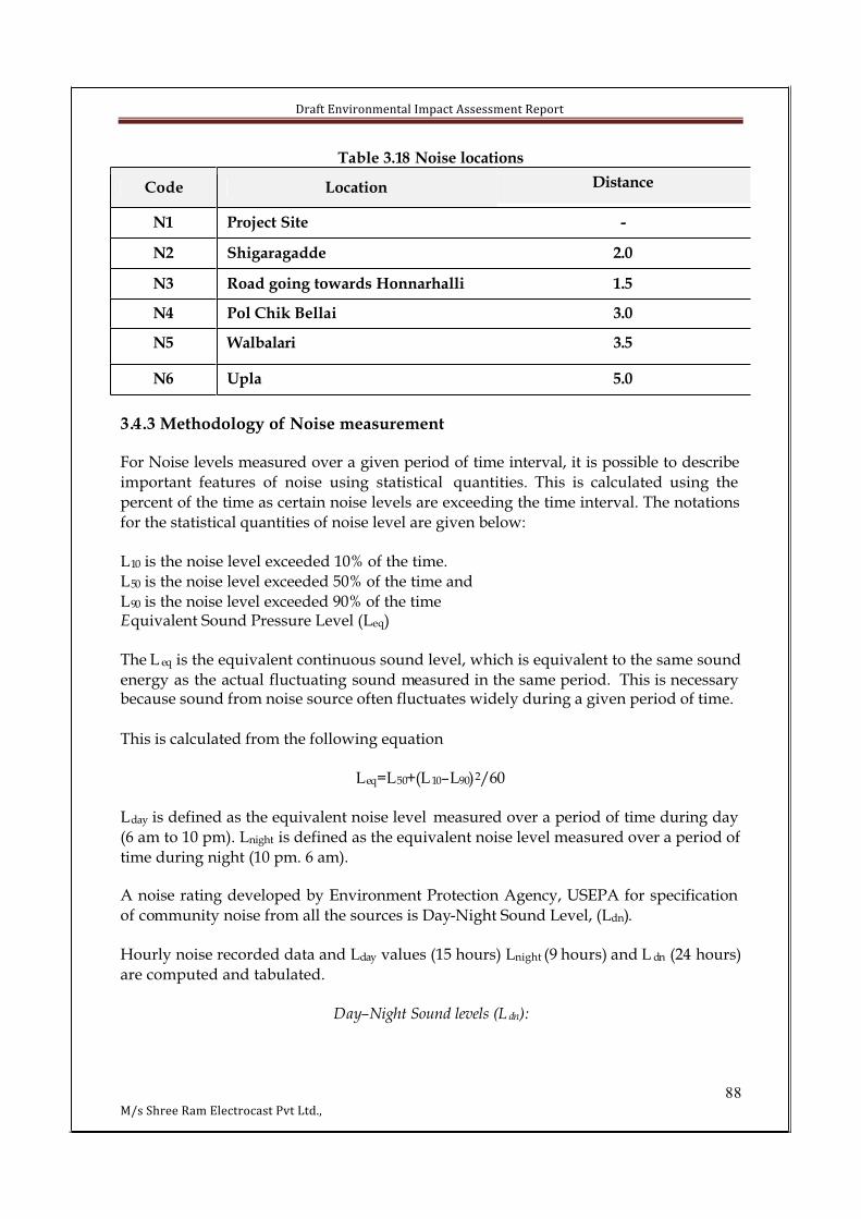
Draft Environmental Impact Assessment Report
88M/s Shree Ram Electrocast Pvt Ltd.,
Table 3.18 Noise locations
Code Location Distance
N1 Project Site -
N2 Shigaragadde 2.0
N3 Road going towards Honnarhalli 1.5
N4 Pol Chik Bellai 3.0
N5 Walbalari 3.5
N6 Upla 5.0
3.4.3 Methodology of Noise measurement
For Noise levels measured over a given period of time interval, it is possible to describe
important features of noise using statistical quantities. This is calculated using the
percent of the time as certain noise levels are exceeding the time interval. The notations
for the statistical quantities of noise level are given below:
L10 is the noise level exceeded 10% of the time.
L50 is the noise level exceeded 50% of the time and
L90 is the noise level exceeded 90% of the timeEquivalent Sound Pressure Level (Leq)
The L eq is the equivalent continuous sound level, which is equivalent to the same sound
energy as the actual fluctuating sound measured in the same period. This is necessary because sound from noise source often fluctuates widely during a given period of time.
This is calculated from the following equation
Leq=L50+(L 10–L90)2/60
Lday is defined as the equivalent noise level measured over a period of time during day
(6 am to 10 pm). Lnight is defined as the equivalent noise level measured over a period of
time during night (10 pm. 6 am).
A noise rating developed by Environment Protection Agency, USEPA for specification
of community noise from all the sources is Day-Night Sound Level, (Ldn).
Hourly noise recorded data and Lday values (15 hours) Lnight (9 hours) and L dn (24 hours)
are computed and tabulated.
Day–Night Sound levels (L dn):
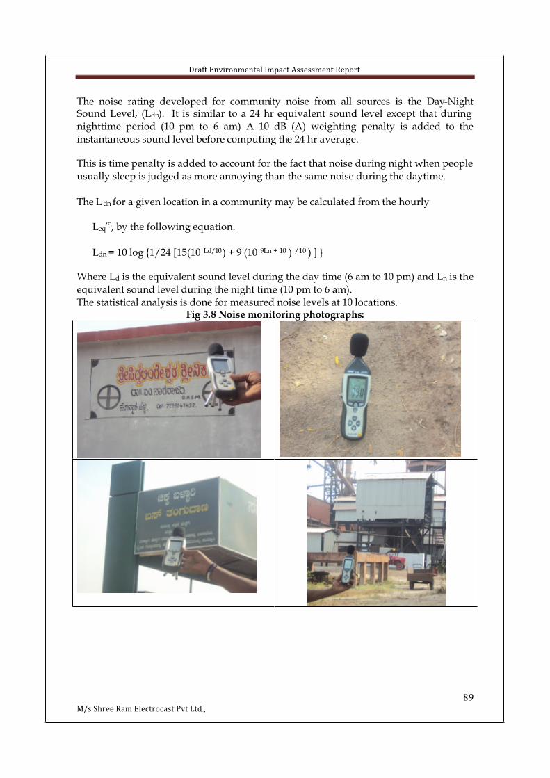
Draft Environmental Impact Assessment Report
89M/s Shree Ram Electrocast Pvt Ltd.,
The noise rating developed for community noise from all sources is the Day-NightSound Level, (Ldn). It is similar to a 24 hr equivalent sound level except that during
nighttime period (10 pm to 6 am) A 10 dB (A) weighting penalty is added to the
instantaneous sound level before computing the 24 hr average.
This is time penalty is added to account for the fact that noise during night when people
usually sleep is judged as more annoying than the same noise during the daytime.
The L dn for a given location in a community may be calculated from the hourly
Leq’S, by the following equation.
Ldn = 10 log {1/24 [15(10 Ld/10) + 9 (10 9Ln + 10 ) /10 ) ] }
Where Ld is the equivalent sound level during the day time (6 am to 10 pm) and Ln is the
equivalent sound level during the night time (10 pm to 6 am).
The statistical analysis is done for measured noise levels at 10 locations.Fig 3.8 Noise monitoring photographs:

Draft Environmental Impact Assessment Report
90M/s Shree Ram Electrocast Pvt Ltd.,
Table 3.19 Summary of Ambient Noise Level Monitoring Results As per Residential Limits Standards- Leq Day- 55 dB(A) and Leq Night- 45 dB(A)
Code LocationLeq Max
dB(A)Leq min
dB(A)
Distancefrom the
Project site (Kms)
N1 Project Site 42.5 35.5 -
N2 Shridaragadde 44.5 39.8 2.0
N3 Road going towards Honnarhalli
48.6 40.51.5
N4 Chikka Bellari 35.4 31.5 3.0
N5 Walbalari 42.7 33.8 3.5
N6 Upla 46.8 37.5 5.0
3.5 WATER ENVIRONMENTStudies on Water Environment aspects of ecosystem is important for Environmental Impact Assessment to identify sensitive issues and take appropriate action by
maintaining ‘ecological homeostasis’ in the early stages of development of the project.
The objective of this report is to define the present environment in which the proposed action is to occur, to evaluate all possible eventualities, to ensure that all negative
impacts are minimized, and to demonstrate that proposed project has beenappropriately announced to all interested parties so that their concerns can be
considered.
3.5.1 Water quality monitoring
Three surface water sample and six Groundwater (Bore well water) samples were
collected in the study area and have been analyzed for describing the baseline water environment. Water is a vital essential commodity necessary for the survival ofvegetation, animals and human beings and for proper balance of eco system itself.
Hence it is necessary to study the quality of water in the study area to find out if
industrial activities in and around the area have caused any deterioration in the
environmental quality with respect to surface and ground water sources, so that the health and growth of humans, flora, fauna and soil conditions are not affected
adversely. This assessment may also serve as a baseline to compare with the post
establishment data for taking necessary corrective measures; if at all any of the
parameter tends to exceed the prescribed limit.The details of these water-sampling stations are given below and their locations are as shown
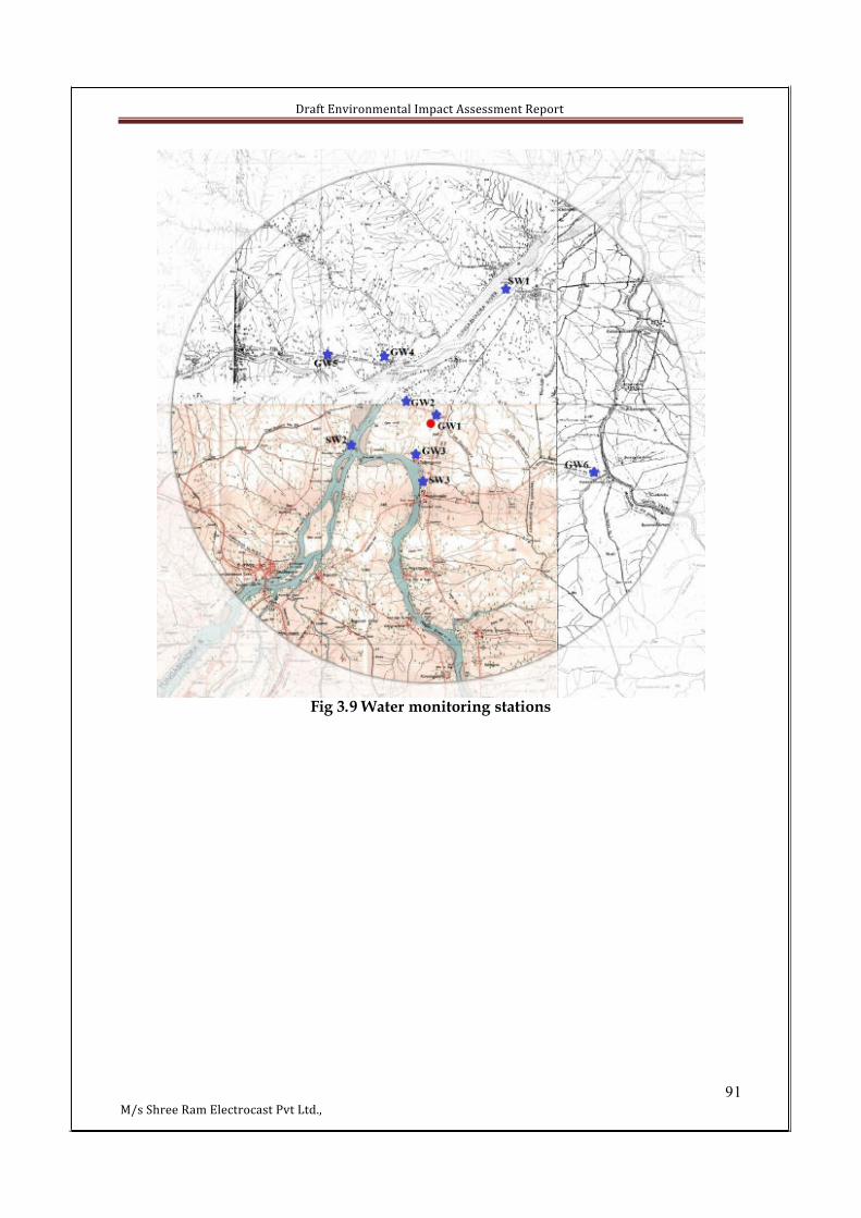
Draft Environmental Impact Assessment Report
91M/s Shree Ram Electrocast Pvt Ltd.,
Fig 3.9 Water monitoring stations
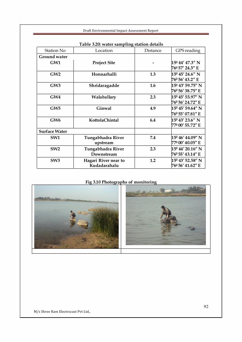
Draft Environmental Impact Assessment Report
92M/s Shree Ram Electrocast Pvt Ltd.,
Table 3.20: water sampling station details
Station No Location Distance GPS reading
Ground water
GW1 Project Site - 150 44’ 47.3” N760 57’ 24.3” E
GW2 Honnarhalli 1.3 150 45’ 24.6” N760 56’ 43.2” E
GW3 Shridaragadde 1.6 150 43’ 59.75” N760 56’ 38.75” E
GW4 Walaballary 2.3 150 45’ 55.97” N760 56’ 24.72” E
GW5 Ginwal 4.9 150 45’ 59.64” N
760 55’ 07.81” E
GW6 KottolaChintal 6.4 150 43’ 23.6” N770 00’ 55.72” E
Surface Water
SW1 Tungabhadra River upstream
7.4 150 46’ 44.09” N770 00’ 40.05” E
SW2 Tungabhadra River Downstream
2.3 150 44’ 20.16” N760 55’ 43.14” E
SW3 Hagari River near to Kudadarahalu
1.2 150 43’ 52.58” N760 56’ 41.62” E
Fig 3.10 Photographs of monitoring

Draft Environmental Impact Assessment Report
93M/s Shree Ram Electrocast Pvt Ltd.,
Table 3.21: Water Quality Results
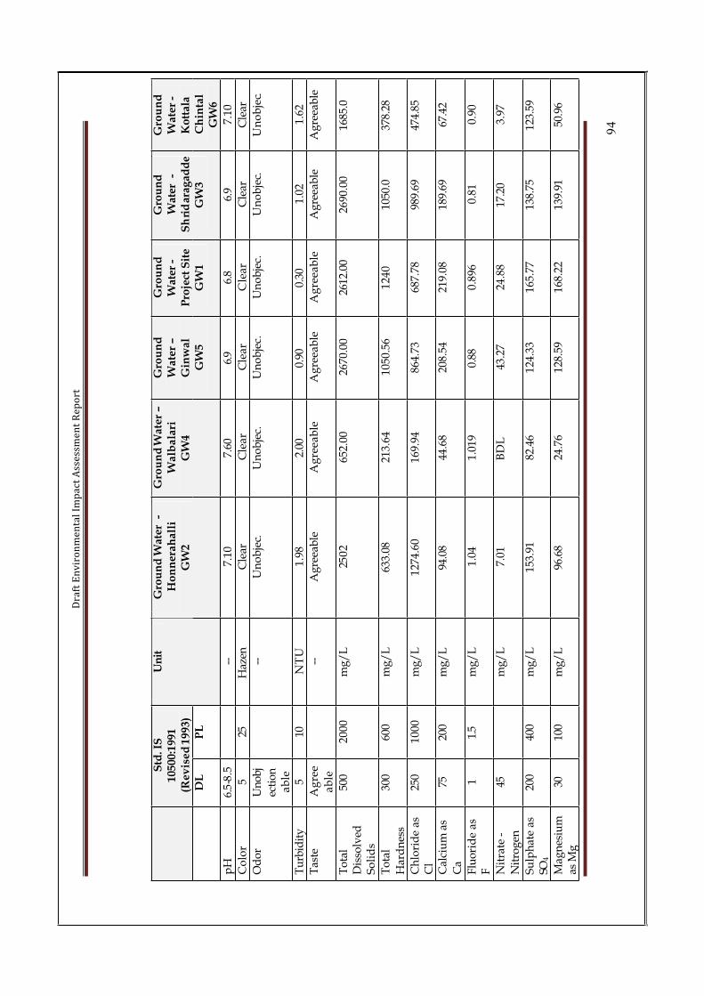
Dra
ft E
nv
iro
nm
en
tal
Imp
act
Ass
ess
me
nt
Re
po
rt
94
Std
. IS
10500:1
991
(Re
vis
ed
19
93
)D
LP
L
Un
itG
rou
nd
Wate
r-
Ho
nn
era
ha
lli
GW
2
Gro
un
dW
ate
r–
Wa
lba
lari
GW
4
Gro
un
dW
ate
r–
Gin
wal
GW
5
Gro
un
dW
ater
-P
roje
ct S
ite
GW
1
Gro
un
dW
ater
-S
hri
dar
agad
de
GW
3
Gro
un
dW
ate
r-
Ko
ttal
aC
hin
tal
GW
6
pH
6.5
-8.5
--7.
107.
606.
96.
86.
97.
10
Co
lor
525
Haz
enC
lear
Cle
arC
lear
Cle
arC
lear
Cle
ar
Od
or
Un
ob
j
ecti
on
ab
le
--U
no
bje
c.U
no
bje
c.U
no
bje
c.U
no
bje
c.U
no
bje
c.U
no
bje
c.
Tu
rbid
ity
510
NT
U1.
982.
000.
900.
301.
021.
62
Tas
teA
gre
e
ab
le
--A
gre
eab
leA
gre
eab
leA
gre
eab
leA
gre
eab
leA
gre
eab
leA
gre
eab
le
To
tal
Dis
solv
edS
oli
ds
500
20
00
mg
/L
250
265
2.00
2670
.00
2612
.00
2690
.00
1685
.0
To
tal
Har
dn
ess
300
600
mg
/L
633.
0821
3.64
1050
.56
12
40
1050
.037
8.28
Ch
lori
de
as
Cl
250
10
00
mg
/L
1274
.60
169.
9486
4.73
687.
7898
9.69
474.
85
Cal
ciu
m a
s
Ca
7520
0m
g/
L94
.08
44.6
820
8.54
219.
0818
9.69
67.4
2
Flu
ori
de
as
F1
1.5
mg
/L
1.04
1.01
90.
880.
896
0.81
0.90
Nit
rate
-
Nit
rog
en
45m
g/
L7.
01B
DL
43.2
72
4.8
817
.20
3.97
Su
lph
ate
as
SO4
200
400
mg
/L
153.
9182
.46
124.
3316
5.77
138.
7512
3.59
Mag
nes
ium
as M
g30
100
mg
/L
96.6
824
.76
128.
5916
8.22
139.
9150
.96

Dra
ft E
nv
iro
nm
en
tal
Imp
act
Ass
ess
me
nt
Re
po
rt
95
Iro
n a
s F
e0.
31
mg
/L
9.70
0.19
BD
LB
DL
0.35
0.41
Fer
rou
s Ir
on
--
mg
/L
3.15
BD
LB
DL
BD
LB
DL
BD
L
Dis
solv
ed
Oxy
gen
--m
g/
L5.
10
5.3
5.20
5.0
5.3
5.3
Alk
alin
ity
200
600
mg
/L
68
043
9.30
655.
5065
7.8
657.
867
7.5
Ars
enic
0.01
mg
/L
BD
LB
DL
BD
LB
DL
BD
LB
DL
Ch
rom
ium
Hex
aval
ent
0.05
mg
/L
BD
LB
DL
BD
LB
DL
BD
LB
DL
Lea
d0.
05m
g/
LB
DL
BD
LB
DL
BD
LB
DL
BD
L
Mer
cury
0.0
01
mg
/L
BD
LB
DL
BD
LB
DL
BD
LB
DL
Nic
kel
--m
g/
LB
DL
BD
LB
DL
BD
LB
DL
0.00
4
Sel
eniu
m0.
01m
g/
LB
DL
BD
LB
DL
BD
LB
DL
BD
L
Zin
c5.
015
.0m
g/
L0.
186
0.03
40.
037
0.0
97
0.14
80.
059
Bo
ron
as
B1
5m
g/
L1.
300.
208
0.61
60.
717
0.77
1.22
Res
idu
alF
ree
Ch
lori
ne
0.2
mg
/L
BD
LB
DL
BD
LB
DL
BD
LB
DL
Cy
anid
e as
C
N0.
05m
g/
LB
DL
BD
LB
DL
BD
LB
DL
BD
L
An
ion
ic
Det
erg
ents
0.2
1.0
mg
/L
BD
LB
DL
BD
LB
DL
BD
LB
DL
Ph
eno
lic
Co
mp
ou
nd
s0.
001
0.00 2
mg
/L
BD
LB
DL
BD
LB
DL
BD
LB
DL
Alu
min
ium
as A
l
0.03
0. 2m
g/
LB
DL
BD
LB
DL
BD
LB
DL
BD
L
Co
pp
er a
s C
u0.
051.
5m
g/
LB
DL
BD
LB
DL
BD
LB
DL
BD
L
Man
gan
ese
a M
n0.
10.
3m
g/
L0.
456
0.01
BD
LB
DL
0.00
30.
011
Sil
ver
as
Ag
--m
g/
L0.
127
BD
LB
DL
BD
LB
DL
BD
L
PA
H--
mg
/L
BD
LB
DL
BD
LB
DL
BD
LB
DL
Min
eral
Oil
0.01
mg
/L
BD
LB
DL
BD
LB
DL
BD
LB
DL
Pes
tici
des
0.0
01
mg
/L
BD
LB
DL
BD
LB
DL
BD
LB
DL
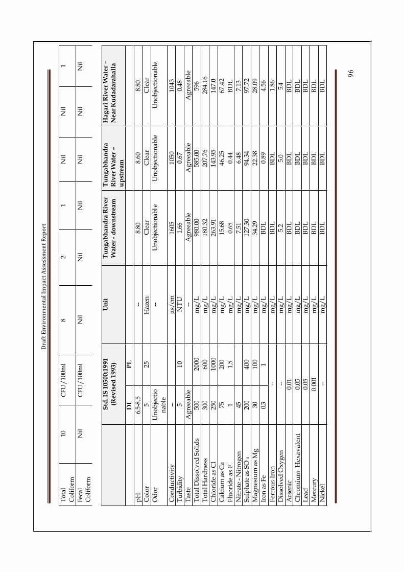
Dra
ft E
nv
iro
nm
en
tal
Imp
act
Ass
ess
me
nt
Re
po
rt
96
To
tal
Co
lifo
rm
10C
FU
/10
0ml
82
1N
ilN
il1
Feca
lC
oli
form
Nil
CF
U/
100m
lN
ilN
ilN
ilN
ilN
ilN
il
Std
. IS
10500:1
991
(Re
vis
ed
19
93
)U
nit
Tu
ng
abh
and
ra R
iver
W
ater
-d
ow
nst
ream
Tu
ng
ab
ha
nd
raR
iver
Wat
er –
up
stre
am
Ha
ga
riR
ive
r W
ate
r –
Ne
ar
Ku
da
da
rah
all
a
DL
PL
pH
6.5
-8.5
--8.
808.
608.
80
Co
lor
52
5H
azen
Cle
arC
lear
Cle
ar
Od
or
Un
ob
ject
io
na
ble
--U
no
bje
ctio
nab
leU
no
bje
ctio
nab
leU
no
bje
ctio
nab
le
Co
nd
uct
ivit
y--
µs/
cm16
051
05
01
04
3T
urb
idit
y5
10
NT
U1.
660.
670.
48
Tas
teA
gre
eab
le--
Ag
reea
ble
Ag
reea
ble
Ag
reea
ble
To
tal D
isso
lved
So
lid
s50
02
00
0m
g/
L98
0.00
585.
0059
6
To
tal H
ard
nes
s30
06
00
mg
/L
180.
3220
7.76
284.
16
Ch
lori
de
as C
l25
01
00
0m
g/
L26
3.91
143.
9514
7.0
Cal
ciu
m a
s C
a75
20
0m
g/
L15
.68
46
.25
67
.42
Flu
ori
de
as F
11.
5m
g/
L0.
650.
44B
DL
Nit
rate
- N
itro
gen
45m
g/
L7.
516.
487.
13S
ulp
hat
e as
SO
420
04
00
mg
/L
127.
309
4.3
49
7.7
2
Ma
gn
esiu
m a
s M
g30
10
0m
g/
L34
.29
22
.38
28
.09
Iro
n a
s F
e0.
31
mg
/L
BD
L0.
894.
56
Fer
rou
s Ir
on
--
mg
/L
BD
LB
DL
1.86
Dis
solv
ed O
xy
gen
--m
g/
L5.
25.
05.
4
Ars
enic
0.01
mg
/L
BD
LB
DL
BD
L
Ch
rom
ium
Hex
av
ale
nt
0.05
mg
/L
BD
LB
DL
BD
LL
ead
0.05
mg
/L
BD
LB
DL
BD
L
Mer
cury
0.00
1m
g/
LB
DL
BD
LB
DL
Nic
kel
--m
g/
LB
DL
BD
LB
DL

Dra
ft E
nv
iro
nm
en
tal
Imp
act
Ass
ess
me
nt
Re
po
rt
97
Sel
eniu
m0.
01m
g/
LB
DL
BD
LB
DL
Zin
c5.
015
.0m
g/
L0.
033
0.0
37
0.0
36
Bo
ron
as
B1
5m
g/
L0.
27B
DL
BD
L
Cy
anid
e as
CN
0.05
mg
/L
BD
LB
DL
BD
L
An
ion
ic D
eter
gen
ts0.
21.
0m
g/
LB
DL
BD
LB
DL
Ph
eno
lic
Co
mp
ou
nd
s0.
001
0.00
2m
g/
LB
DL
BD
LB
DL
Alu
min
ium
as
Al
0.03
0.2
mg
/L
BD
LB
DL
BD
L
Co
pp
er a
s C
u0.
051.
5m
g/
LB
DL
BD
LB
DL
Man
gan
ese
a M
n0.
10.
3m
g/
L0.
020
0.0
35
0.27
Sil
ver
as
Ag
--m
g/
L0.
126
0.1
10
0.1
09
PA
H--
mg
/L
BD
LB
DL
BD
L
Min
eral
Oil
0.01
mg
/L
BD
LB
DL
BD
L
Pes
tici
des
0.00
1m
g/
LB
DL
BD
LB
DL
So
diu
m A
bso
rpti
on
Ra
tio
--m
eq/
lt12
.96
5.74
10.2
1
Per
cen
t So
diu
m--
%82
.866
.672
.3
To
tal C
oli
form
10
CF
U/
100m
l3
22
Feca
lCo
lifo
rmN
ilC
FU
/10
0ml
Nil
Nil
1

Draft Environmental Impact Assessment Report
98
Hydrology, Geology, hydromorphology and water quality studies have been carried out in the study area to understand the availability of water resources, possibility of water
contamination and existing water quality
3.6 HydrologyReconnaissance survey of the study area was carried out during the post-monsoonseason and various sampling locations for monitoring various
hydrological/hydrogeological parameters have been identified. Subsequently, field
study has been commenced for collecting information on water levels, aquiferparameters, surface storage etc., at the selected locations. The other studies such as
climate/rainfall, geology, historical water levels etc., have been based on secondary data
collected from various government and semi-government agencies.
3.6.1 Hydrometeorology
The climate of an area is the synthesis of weather conditions that have prevailed over a long period of time. This synthesis involves both average of the climatic elements and
measurements of variability (such as extreme values & probabilities). Climate is acomplex, abstract concept involving data on temperature, humidity, precipitation type
and amount, wind speed and direction, atmospheric pressure, sunshine, cloud types
and coverage and such weather phenomena as fog, thunderstorms and frost and the
relationships among them. Climate is never stable but is subject to continuingoscillations and therefore it is time dependent.
3.6.2 Rainfall
In the study area and environs, the rainfall occurs mainly in the form of rain. Theamount of annual rainfall recorded at the Bellary station for the period from 2006 to 2010 is presented in tabular form below.
The onset of southwest monsoon is normally during the first week of June and iswithdrawn by the end of September.
During this period, the area receives 699.4 mm of rainfall on an average.
In 2010, area received 861.8 mm rainfall out of which, during August maximum of 298.8 mm rainfall was observed. This rainfall accounts for 42.7% of the annual rainfall. Period
from October to December constitute the northeast monsoon season. During this period, the area receives 226.5 mm of rainfall on an average accounting for 32.3% of the annual
rainfall.
During March to May about 114.8 mm of rainfall was occurred.
Overall, the area receives 699.4 mm of rainfall annually on an average (from 2006-10).
The annual rainfall data for the period 2006 to 10 has been taken into consideration for
studying the variability or rainfall over study area with time. The year to year variation
of rainfall is conspicuous. The heaviest rainfall of 914.5 mm was recorded in 2009 and

Draft Environmental Impact Assessment Report
99
the lowest rainfall of 528.3 mm was recorded in 2006. The 5 years moving average and the line of best fit indicate zigzag trend of rainfall. The annual trend of rainfall for the
period 2006-10 is given in Table below.
Table 3.22 Monthly Annual Rainfall Distributions
Jan Feb Mar Apr May June July Aug Sept Oct Nov Dec Annual
Rainfall
2006 0 0 26.2 14.4 95.6 87.1 47.0 28.1 130.6 38.1 61.2 0.0 528.3
2007 0 0 2.1 3.2 51.9 143.1 71.3 65.1 225.4 82.0 6.1 0.2 650.4
2008 0 10.7 100.0 2.6 36.6 33.6 31.6 100.4 139.7 57.4 29.6 0.0 542.2
2009 0 0 6.3 6.7 69.4 76.9 34.9 108.8 266.2 265.2 68.0 12.1 914.5
2010 19.2 2.7 0.0 25.9 88.9 58.7 76.3 298.8 64.8 98.6 127.4 0.5 861.8
Source: IMD
3.7 Geology and Structures
3.7.1 Regional Geology
The geological history of Karnataka is largely confined to the two oldest eras.
1. The Archean
2. The Proterozoic
The rest of the great periods from Cambrian to recent hardly represented but for minor
sediments of recent age along the coastal margin to the west. Thus the belt of the rocks
of Karnataka are Archean in age going back to the very dawn of geological history. The
study area largely falls in the basin of Tungabhadra river. The area is marked with undulating topography with granite hills and few chains of hills composed of Dharwar
schist. The geological Time-Scale in Karnataka is as given below.
• Laterite, alluvium black soils
• Coastal Teritary,
• Deccan Volcanic
• Bhima
• Badami
• Closepet Granite
• Dharwar Schist Belt
• Kolar type auriferous schist belt
3.8 HydrogeologyHydrogeologyNumerous small streams flowing in southern direction towards the Thungabhadra river
crisscross the study area. The prominent stream in the study area is Garchi vanka which
flows in the northern direction and ultimately empties into Thungabhadra river near
Maturu. There are no major ponds in the area. The small ponds and streams carry water only during and just after monsoon season.
Draft Environmental Impact Assessment Report
100
Thungabhadra river is located in the North West direction and flowing east. All the streams finally join with the Thungabhadra river. The left and right bank canal from the
Thungabhadra river caters to most of the agricultural irrigation needs.
Occurrence and movement of ground water in Rock FormationsThe joints and other openings in the gneiss and granites, the pore spaces in the zone of
weathering and bedding planes of the metamorphosized sediments determine the rate
of percolation of water into sub-surface and the yield of the wells in the region. Black
cotton soil allows water to infiltrate slowly after saturation. The impervious calcareous clay bed, below the black cotton soil prevents the downward movement of water.
Whether, the areas covered by red loam/sandy soils have relatively greater percolation
because of its relatively high porosity and permeability.Occurrence of ground water thus, is mainly controlled by water conditions. The
recharge of the ground water is mainly due to the rainfall, which is scanty in the region. Therefore, the depth of water table is just near the surface in the wells bordering the
canals.
Due to the inadequate data available on ground water conditions, estimations of ground
water movement in the study area could not be possible. However, considering the overall features, the ground water movement appears to be from north-west to south
and from south-east towards the Thungabhadra river.
Hydrogeological study conducted within 10 kms radius of the proposed project site is as follows:

Draft Environmental Impact Assessment Report
101
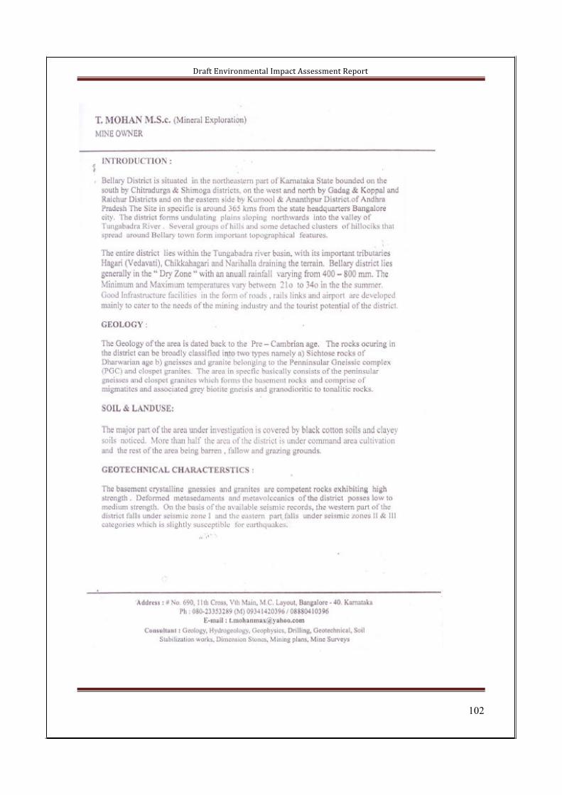
Draft Environmental Impact Assessment Report
102
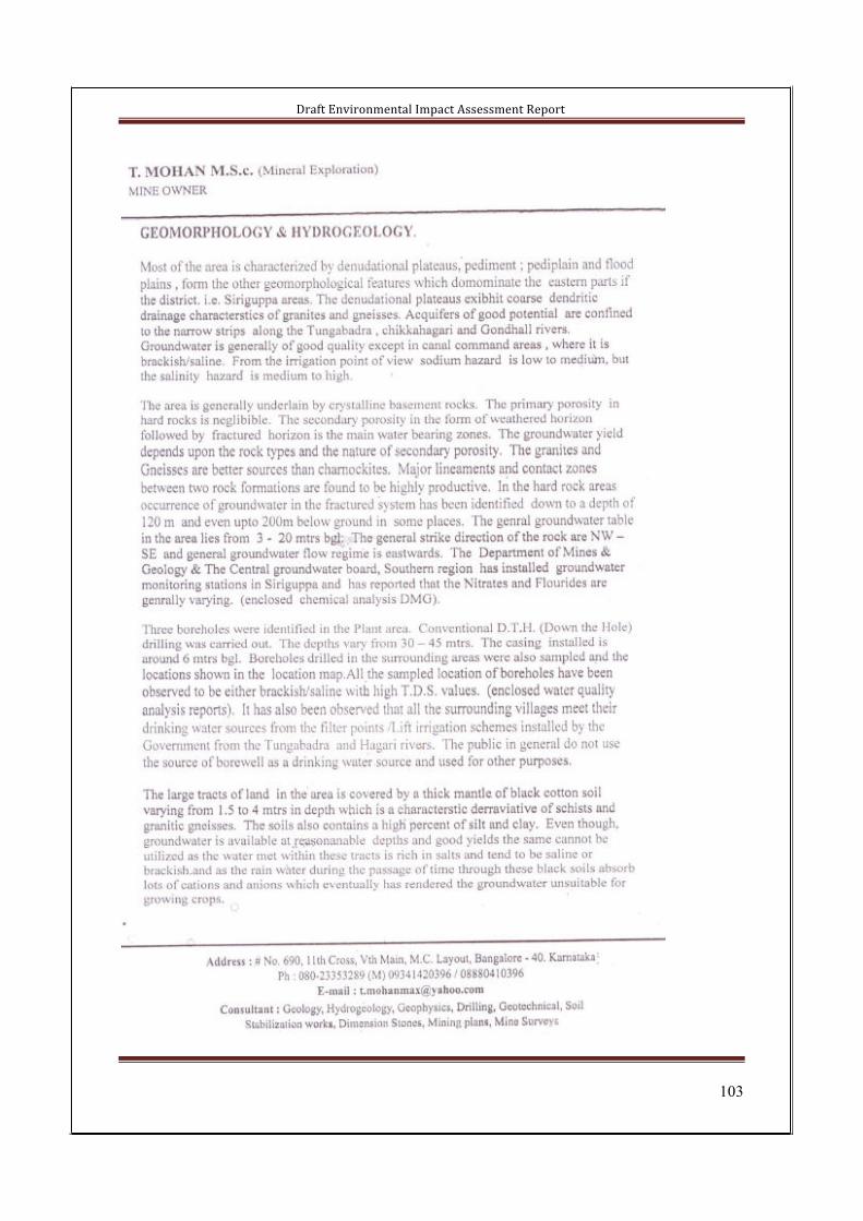
Draft Environmental Impact Assessment Report
103

Draft Environmental Impact Assessment Report
104
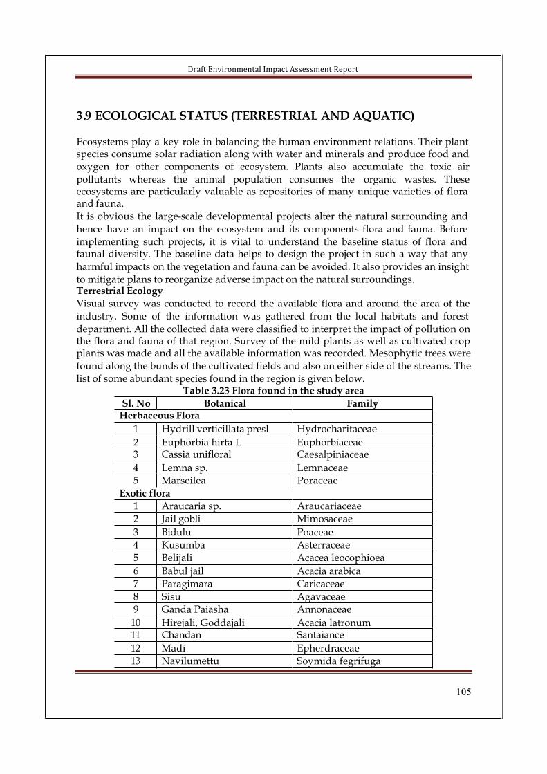
Draft Environmental Impact Assessment Report
105
3.9 ECOLOGICAL STATUS (TERRESTRIAL AND AQUATIC)
Ecosystems play a key role in balancing the human environment relations. Their plant species consume solar radiation along with water and minerals and produce food and
oxygen for other components of ecosystem. Plants also accumulate the toxic air
pollutants whereas the animal population consumes the organic wastes. Theseecosystems are particularly valuable as repositories of many unique varieties of flora and fauna.
It is obvious the large-scale developmental projects alter the natural surrounding and
hence have an impact on the ecosystem and its components flora and fauna. Before
implementing such projects, it is vital to understand the baseline status of flora and faunal diversity. The baseline data helps to design the project in such a way that any
harmful impacts on the vegetation and fauna can be avoided. It also provides an insight
to mitigate plans to reorganize adverse impact on the natural surroundings.Terrestrial Ecology
Visual survey was conducted to record the available flora and around the area of the
industry. Some of the information was gathered from the local habitats and forest
department. All the collected data were classified to interpret the impact of pollution on the flora and fauna of that region. Survey of the mild plants as well as cultivated crop plants was made and all the available information was recorded. Mesophytic trees were
found along the bunds of the cultivated fields and also on either side of the streams. The
list of some abundant species found in the region is given below.Table 3.23 Flora found in the study area
Sl. No Botanical FamilyHerbaceous Flora
1 Hydrill verticillata presl Hydrocharitaceae
2 Euphorbia hirta L Euphorbiaceae3 Cassia unifloral Caesalpiniaceae
4 Lemna sp. Lemnaceae
5 Marseilea Poraceae
Exotic flora
1 Araucaria sp. Araucariaceae
2 Jail gobli Mimosaceae
3 Bidulu Poaceae
4 Kusumba Asterraceae
5 Belijali Acacea leocophioea
6 Babul jail Acacia arabica
7 Paragimara Caricaceae
8 Sisu Agavaceae
9 Ganda Paiasha Annonaceae
10 Hirejali, Goddajali Acacia latronum11 Chandan Santaiance
12 Madi Epherdraceae
13 Navilumettu Soymida fegrifuga
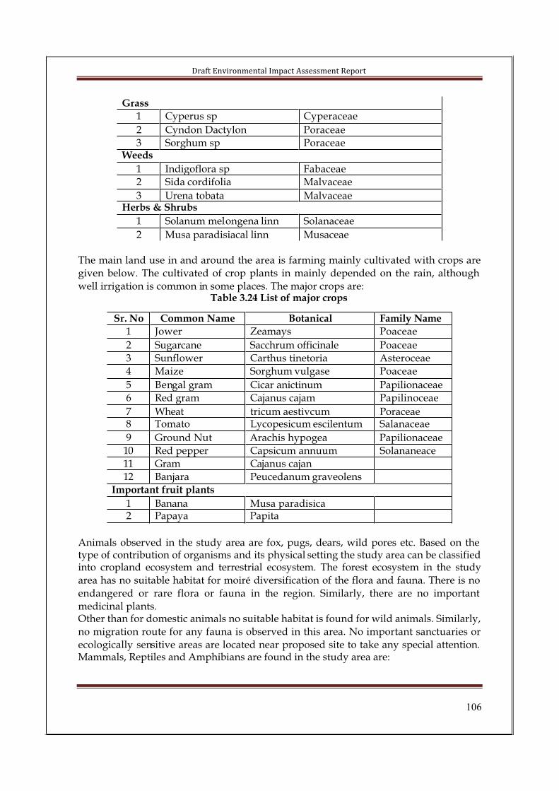
Draft Environmental Impact Assessment Report
106
Grass
1 Cyperus sp Cyperaceae
2 Cyndon Dactylon Poraceae
3 Sorghum sp PoraceaeWeeds
1 Indigoflora sp Fabaceae
2 Sida cordifolia Malvaceae
3 Urena tobata MalvaceaeHerbs & Shrubs
1 Solanum melongena linn Solanaceae
2 Musa paradisiacal linn Musaceae
The main land use in and around the area is farming mainly cultivated with crops are
given below. The cultivated of crop plants in mainly depended on the rain, although
well irrigation is common in some places. The major crops are:Table 3.24 List of major crops
Sr. No Common Name Botanical Family Name
1 Jower Zeamays Poaceae
2 Sugarcane Sacchrum officinale Poaceae
3 Sunflower Carthus tinetoria Asteroceae
4 Maize Sorghum vulgase Poaceae
5 Bengal gram Cicar anictinum Papilionaceae
6 Red gram Cajanus cajam Papilinoceae
7 Wheat tricum aestivcum Poraceae8 Tomato Lycopesicum escilentum Salanaceae
9 Ground Nut Arachis hypogea Papilionaceae
10 Red pepper Capsicum annuum Solananeace
11 Gram Cajanus cajan
12 Banjara Peucedanum graveolens
Important fruit plants
1 Banana Musa paradisica2 Papaya Papita
Animals observed in the study area are fox, pugs, dears, wild pores etc. Based on the type of contribution of organisms and its physical setting the study area can be classified into cropland ecosystem and terrestrial ecosystem. The forest ecosystem in the study
area has no suitable habitat for moiré diversification of the flora and fauna. There is no
endangered or rare flora or fauna in the region. Similarly, there are no important
medicinal plants.Other than for domestic animals no suitable habitat is found for wild animals. Similarly,
no migration route for any fauna is observed in this area. No important sanctuaries or
ecologically sensitive areas are located near proposed site to take any special attention. Mammals, Reptiles and Amphibians are found in the study area are:

Draft Environmental Impact Assessment Report
107
Table 3.25 List of fauna found in the study areaSr. No Common Name Scientific name Feeding Niche
Mammals
1 Bat Rhinolopus spp. Fruits, insects etc
2 Jungle cat Felis chous Carnivorous
3 Bannet Monkey Macaca radiate Fruits, leave, spiders
4 Field mouse Rattus rattus Grains, insects, etc
Reptiles
1 Cobra Naja naja
2 Krait Bungarus coeruleus
3 Rat snake Ptyas mucosus
4 Wall lizard Hemidactylus brooki5 Garden lizard Calotes versicolor
Amphibians
1 Common Frog Rana tigrina2 Toad Bufo melanostictus
Birds
1 Domestic sparrow Passer domesticus
2 Golden headed woodpecker Dinopium benghalense
3 Koel Eduynamys scolopacea
4 Indian myna Acrodontherus tristis
5 Spotted dove Streptopela chiensis
6 Small blue king fisher Alcedo atthis
Aquatic EcologyThe perennial river Thungabhadra and its tributaries Hagari and Chikhagari are
flowing in the region of the project site. Other surface water sources are the seasonal
nallahs and these seasonal nallahs will drain the rain water from the area during rainy season. Since, these nallahs are seasonal in nature. There are some valley/drains spread
over the surrounding area, all join together and flowing towards North-west, joining Thungabhadra River.
List of Phytoplanktons and zooplanktons in Thungabhadra river is given below.Table 3.27 List of aqua fauna
Phytoplankton Zooplankton
Aphanizomeenon flos-aque Rotifer
Melosira granulate Brachionus sp
Scenedesmus obliquus Ephiphanus sp
Nostoc pruniforme Dapnia sp
Euglena acus Crustacean larva sp
Euglena pisciformis
Microcystis flos aque
Nitzschia sigma

Draft Environmental Impact Assessment Report
108
3.1 0 Demographic dataExtract of demographic details obtained from Census department is enclosed as Annexure-2
Draft Environmental Impact Assessment Report
109
CHAPTER-IV ANTICIPATED IMPACTS
4.0 Introduction
Prediction of impacts is the most important component in the environmental impact
assessment studies. Several scientific techniques and methodologies are available to predict impacts of project developmental activities on environment. Such predictions
are superimposed over the baseline (proposed project) status of environmental quality
to derive the ultimate (post-project) scenario of environmental conditions. Theprediction of impacts helps to prepare the Environmental Management Plan (EMP)required to be executed during the on-going activities for the proposed project to
minimize the adverse impacts on environmental quality.
The mathematical models are the best tools to quantitatively describe the cause-effectrelationships between sources of pollution and different components of environment. In
case, mathematical models are not available or it is not possible to identify/validate a
model for a particular situation, predictions could be made through available scientific
knowledge and judgments.
The environmental impacts can be categorized as either primary or secondary. Primary
impacts are those, which are attributable directly to the project, secondary impacts are
those, which are indirectly induced and typically include the associated investment and changed pattern of social and economic activities by the proposed action.
The impacts have been prepared for the proposed expansion assuming that the
pollution due to the existing activities has already been covered under baselineenvironmental monitoring and continue to remain the same during the operation of the
project. The proposed project would create impact on the environment in two distinct
phases.
• During the construction phase which may be regarded as temporary or
short term; and
• During the operation phase which would have long-term effects.
The construction and operational phase of the proposed expansion project comprises various activities each of which may have an impact on some or other environmental
parameters. Various impacts during the construction and operation phase on theenvironmental parameters have been studied to estimate the impact on the
environment. The details on impact of the project activity on each of the above
environmental attributes are discussed below.

Dra
ft E
nv
iro
nm
en
tal
Imp
act
Ass
ess
me
nt
Re
po
rt
11
0
4.1
AN
TIC
IPA
TE
D E
NV
IRO
NM
EN
TA
L I
MP
AC
TS
AN
D M
ITIG
AT
ION
ME
AS
UR
ES
Tab
le 4
.1 I
MP
AC
T I
DE
NT
IFIC
AT
ION
MA
TR
IXE
NV
IRO
NM
EN
TA
L A
TT
RIB
UT
ES
Air
No
ise
Su
rfac
e
Wat
er
Gro
un
d
wat
er
Cli
mat
eL
and
/so
il
Eco
log
yS
oci
o
Eco
no
mic
s
Aes
thet
ics
Hea
lth
Sl.
No
AC
TIV
ITIE
S
CO
NS
TR
UC
TIO
N P
HA
SE
1.S
ite
Cle
ari
ng
/lev
elin
g
��
��
�
2.E
xca
vat
ion
act
ivit
ies
��
�
3.R
ead
y-m
ix c
on
cret
e p
rep
arat
ion
(in
dir
ect)
��
�
4.T
ran
spo
rtat
ion
of
Co
nst
ruct
ion
mat
eria
ls
��
�
5.C
on
stru
ctio
nac
tiv
itie
s o
n l
and
��
��
�
6.L
ay
ing
of
roa
ds
��
��
7.L
abo
ur
cam
ps
��
��
��
8.
Mo
vem
ent
of
Veh
icle
s�
�

Dra
ft E
nv
iro
nm
en
tal
Imp
act
Ass
ess
me
nt
Re
po
rt
11
1
9.C
on
stru
ctio
n D
ebri
s�
�
10.
Ex
cav
ate
d E
art
h�
11.
Dis
po
sal
of
Sew
age
��
��
12.
Dis
po
sal
of
So
lid
w
aste
��
�
13.
Sta
gn
atio
n o
f w
ater
�
14.
Sto
rm W
ater
��
15.
Ru
no
ff�
�
OP
ER
AT
ION
PH
AS
E
1.O
per
atio
n o
f p
ig
iro
n p
lan
t�
��
��
�
2.O
per
atio
n o
f co
ke
ov
en p
lan
t�
��
��
�
3.O
per
atio
n o
f D
IP
pla
nt
��
��
��
4.O
per
atio
n o
f C
apti
ve
po
wer
p
lan
t
��
��
��
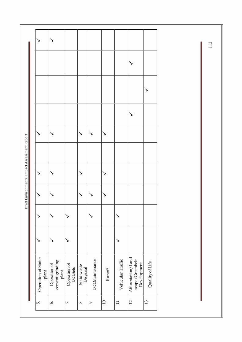
Dra
ft E
nv
iro
nm
en
tal
Imp
act
Ass
ess
me
nt
Re
po
rt
11
2
5.O
per
atio
n o
f S
inte
r
pla
nt
��
��
��
6.O
per
atio
n o
f
cem
ent
gri
nd
ing
p
lan
t
��
��
��
7O
per
ati
on
of
D.G
.Set
s�
�
8S
oli
d w
aste
D
isp
osa
l�
��
9D
.G.M
ain
ten
ance
��
�
10R
un
off
��
�
11V
ehic
ula
r T
raff
ic�
�
12A
ffo
rest
atio
n/
Lan
dsc
ape/
Gre
enb
elt
Dev
elo
pm
ent
��
13Q
ua
lity
of L
ife
�
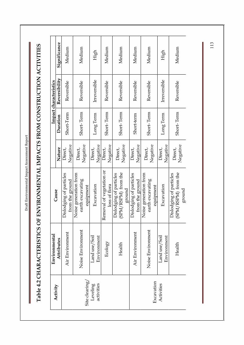
Dra
ft E
nv
iro
nm
en
tal
Imp
act
Ass
ess
me
nt
Re
po
rt
11
3
Ta
ble
4.2
CH
AR
AC
TE
RIS
TIC
S O
F E
NV
IRO
NM
EN
TA
L I
MP
AC
TS
FR
OM
CO
NS
TR
UC
TIO
N A
CT
IVIT
IES
Imp
act
char
acte
rist
ics
Act
ivit
yE
nv
iro
nm
en
tal
Att
rib
ute
sC
ause
Nat
ure
Du
rati
on
Rev
ersi
bil
ity
Sig
nif
ica
nce
Air
En
vir
on
men
tD
islo
dg
ing
of
par
ticl
es
fro
m t
he
gro
un
d
Dir
ect,
Neg
ativ
eS
ho
rt-T
erm
Rev
ersi
ble
Med
ium
No
ise
En
vir
on
men
tN
ois
e g
ener
atio
n f
rom
ea
rth
ex
cav
ati
ng
equ
ipm
ent
Dir
ect,
Neg
ativ
eS
ho
rt-
Ter
mR
ever
sib
leM
ediu
m
Lan
d u
se/
So
il
En
vir
on
men
tE
xca
va
tio
nD
irec
t,
Neg
ativ
eL
on
g T
erm
Irre
ver
sib
leH
igh
Eco
log
yR
emo
val
of
veg
etat
ion
or
loss
of
flo
ra
Dir
ect,
Neg
ativ
eS
ho
rt-
Ter
mR
ever
sib
leM
ediu
m
Sit
e cl
eari
ng
/
Lev
elin
ga
ctiv
itie
s
Hea
lth
Dis
lod
gin
g o
f p
arti
cles
(SP
M/
RS
PM
) f
rom
th
e g
rou
nd
Dir
ect,
Neg
ativ
eS
ho
rt-
Ter
mR
ever
sib
leM
ediu
m
Air
En
vir
on
men
tD
islo
dg
ing
of
par
ticl
es
fro
m t
he
gro
un
d
Dir
ect,
Neg
ativ
eS
ho
rt-t
erm
Rev
ersi
ble
Med
ium
No
ise
En
vir
on
men
tN
ois
e g
ener
atio
n f
rom
ea
rth
ex
cav
ati
ng
equ
ipm
ent
Dir
ect,
Neg
ativ
eS
ho
rt-
Ter
mR
ever
sib
leM
ediu
m
Lan
d u
se/
So
il
En
vir
on
men
tE
xca
va
tio
nD
irec
t,
Neg
ati
ve
Lo
ng
Ter
mIr
rev
ersi
ble
Hig
h
Ex
cav
ati
on
Act
ivit
ies
Hea
lth
Dis
lod
gin
g o
f p
arti
cles
(SP
M/
RS
PM
) f
rom
th
e
gro
un
d
Dir
ect,
Neg
ativ
eS
ho
rt-
Ter
mR
ever
sib
leM
ediu
m

Dra
ft E
nv
iro
nm
en
tal
Imp
act
Ass
ess
me
nt
Re
po
rt
11
4
Rea
dy
Mix
Co
ncr
ete
pre
par
atio
n
No
ise
En
vir
on
men
tN
ois
e g
ener
atio
n f
rom
bat
chin
g p
lan
ts/
too
ls,
mac
hin
erie
s
Dir
ect,
Neg
ati
ve
Sh
ort
- T
erm
Rev
ersi
ble
Med
ium
Lan
d u
se/
So
il
En
vir
on
men
tM
ixin
g u
p w
ith
so
ilD
irec
t,
Neg
ativ
eS
ho
rt T
erm
Rev
ersi
ble
Lo
w
Air
En
vir
on
men
t
Tra
nsp
ort
of
con
stru
ctio
n
mat
eria
l in
tru
cks
&
Ex
hau
st e
mis
sio
n f
rom
veh
icle
s
Dir
ect,
Neg
ativ
eS
ho
rt-
Ter
mR
ever
sib
leM
ediu
m
No
ise
En
vir
on
men
tN
ois
e g
ener
atio
n f
rom
v
ehic
les
Dir
ect,
Neg
ativ
eS
ho
rt-
Ter
mR
ever
sib
leL
ow
Tra
nsp
ort
ati
on
of
con
stru
ctio
n
mat
eria
ls
Hea
lth
Ris
k o
f ac
cid
ents
du
rin
g
tran
sit
Dir
ect,
Neg
ativ
eS
ho
rt-
Ter
mR
ever
sib
leM
ediu
m
Air
En
vir
on
men
t
Op
era
tio
n o
f co
nst
ruct
ion
mac
hin
ery
,
wel
din
g a
ctiv
itie
s a
nd
oth
ers
Dir
ect,
Neg
ativ
eS
ho
rt-
Ter
mR
ever
sib
leL
ow
No
ise
En
vir
on
men
tN
ois
e g
ener
atio
n f
rom
u
se o
f m
ach
iner
yD
irec
t,N
egat
ive
Sh
ort
- T
erm
Rev
ersi
ble
Med
ium
Lan
d u
se/
So
il
En
vir
on
men
tS
etti
ng
up
of
Pro
ject
Dir
ect,
Neg
ativ
eL
on
g T
erm
Irre
ver
sib
leL
ow
Eco
log
yL
oss
of
veg
etat
ion
Dir
ect,
Neg
ativ
eS
ho
rt-T
emR
ever
sib
leM
ediu
m
Co
nst
ruct
ion
act
ivit
ies
on
La
nd
Hea
lth
Var
iou
s co
nst
ruct
ion
act
ivit
ies
Dir
ect,
Neg
ativ
eS
ho
rt-T
emR
ever
sib
leL
ow
La
yin
g o
f
Ro
ads
Air
En
vir
on
men
tO
per
ati
on
of
con
stru
ctio
n m
ach
iner
y,
Mo
vem
ent
of
Veh
icle
s
Dir
ect,
Neg
ativ
eS
ho
rt-
Ter
mR
ever
sib
leH
igh

Dra
ft E
nv
iro
nm
en
tal
Imp
act
Ass
ess
me
nt
Re
po
rt
11
5
No
ise
En
vir
on
men
tN
ois
e g
ener
atio
n f
rom
use
of
mac
hin
ery
,V
ehic
ula
r m
ov
emen
t
Dir
ect,
Neg
ativ
eS
ho
rt-
Ter
mR
ever
sib
leH
igh
Lan
d u
se/
So
il
En
vir
on
men
tD
evel
op
men
t o
f R
oa
ds
Dir
ect,
Neg
ativ
eL
on
g T
erm
Irre
ver
sib
leM
ediu
m
Eco
log
yL
oss
of
veg
etat
ion
Dir
ect,
Neg
ativ
eS
ho
rt-T
erm
Rev
ersi
ble
Med
ium
Air
En
vir
on
men
tB
urn
ing
of
Fu
els
Dir
ect,
Neg
ativ
eS
ho
rt-T
erm
Rev
ersi
ble
Lo
w
Wat
er E
nv
iro
nm
ent
(Su
rfa
ce a
nd
Gro
un
d)
Dis
po
sal
of
Sew
ag
eD
irec
t,N
egat
ive
Sh
ort
-Ter
mR
ever
sib
leH
igh
Lan
d/
So
il
En
vir
on
men
tD
isp
osa
l o
f S
ewa
ge
InD
irec
t,
Neg
ativ
eS
ho
rt-T
emR
ever
sib
leM
ediu
m
So
cio
-Eco
no
mic
Em
plo
ym
ent
Op
po
rtu
nit
ies,
In
flu
x o
f
peo
ple
InD
irec
t,
Neg
ativ
eS
ho
rt-T
erm
Rev
ersi
ble
Med
ium
Lab
ou
r C
amp
s
Hea
lth
Dis
po
sal
of
Sew
age/
So
lid
was
tes
Dir
ect,
Neg
ativ
eS
ho
rt–T
erm
Rev
ersi
ble
Hig
h
Air
En
vir
on
men
tT
ran
spo
rta
tio
n o
f C
on
stru
ctio
n M
ater
ials
Dir
ect,
Neg
ativ
eS
ho
rt–T
erm
Rev
ersi
ble
Med
ium
Mo
vem
ent
of
Veh
icle
sN
ois
e E
nv
iro
nm
ent
Veh
icu
lar
mo
vem
ent
Dir
ect,
Neg
ativ
eS
ho
rt–T
erm
Rev
ersi
ble
Lo
w
Co
nst
ruct
ion
Deb
ris
Lan
d/
So
il
En
vir
on
men
t
Var
iou
s co
nst
ruct
ion
wo
rks
Dir
ect,
Neg
ativ
eS
ho
rt–T
erm
Rev
ersi
ble
Lo
w
Ex
cav
ate
dE
art
h/
Mu
ckL
and
/S
oil
En
vir
on
men
tF
ou
nda
tio
n w
ork
sD
irec
t,N
egat
ive
Sh
ort
–Ter
mR
ever
sib
leM
ediu
m
Dis
po
sal
of
Sew
ag
e
Wat
er E
nv
iro
nm
ent
(Su
rfa
ce a
nd
Gro
un
d)
Do
mes
tic
acti
vit
ies
fro
m
La
bo
ur
cam
ps
Dir
ect,
Neg
ativ
eS
ho
rt-T
erm
Rev
ersi
ble
Hig
h

Dra
ft E
nv
iro
nm
en
tal
Imp
act
Ass
ess
me
nt
Re
po
rt
11
6
Aes
thet
ics
Od
ou
r n
uis
an
ceIn
Dir
ect,
Neg
ativ
eS
ho
rt-T
erm
Rev
ersi
ble
Med
ium
Hea
lth
Dis
po
sal
of
Sew
ag
eD
irec
t,
Neg
ativ
eS
ho
rt–T
erm
Rev
ersi
ble
Hig
h
Lan
d/
So
il
En
vir
on
men
t
So
lid
was
te g
ener
atio
n,
La
nd
co
nta
min
ati
on
Dir
ect,
Neg
ativ
eS
ho
rt–T
erm
Rev
ersi
ble
Med
ium
Aes
thet
ics
Od
ou
r n
uis
ance
InD
irec
t,
Neg
ativ
eS
ho
rt-T
erm
Rev
ersi
ble
Med
ium
Dis
po
sal
of
So
lid
was
tes
Hea
lth
Deg
rad
atio
n o
f S
oli
d
was
te,
attr
acti
on
of
flie
s
Dir
ect,
Neg
ativ
eS
ho
rt–T
erm
Rev
ersi
ble
Med
ium
Sta
gn
atio
n o
f W
ater
Hea
lth
Mo
squ
ito
bre
edin
g s
ites
Dir
ect,
Neg
ativ
eS
ho
rt–T
erm
Rev
ersi
ble
Hig
h
Wat
er E
nv
iro
nm
ent
(Su
rfa
ce)
Co
nst
ruct
ion
sit
e ar
eas
Dir
ect,
Neg
ativ
eS
ho
rt-T
erm
Rev
ersi
ble
Med
ium
Sto
rm w
ater
R
un
-off
Lan
d/
So
il
En
vir
on
men
tF
loo
din
gD
irec
t,
Neg
ativ
eS
ho
rt–T
erm
Rev
ersi
ble
Hig
h

Dra
ft E
nv
iro
nm
en
tal
Imp
act
Ass
ess
me
nt
Re
po
rt
11
7
Tab
le 4
.3:
CH
AR
AC
TE
RIS
TIC
S O
F E
NV
IRO
NM
EN
TA
L I
MP
AC
TS
FR
OM
OP
ER
AT
ION
AL
PH
AS
E
Imp
act
char
acte
rist
ics
Act
ivit
yE
nv
iro
nm
en
tal
Att
rib
ute
sC
ause
Na
ture
Du
rati
on
Rev
ersi
bil
ity
Sig
nif
ica
nce
Air
En
vir
on
men
tO
per
atio
n o
f B
last
furn
ace
Dir
ect,
Neg
ativ
e
Lo
ng
-
Ter
mR
ever
sib
leH
igh
Op
erat
ion
of
Pig
Ir
on
pla
nt
No
ise
En
vir
on
men
t
Op
erat
ion
of
Bla
st
furn
ace
Dir
ect,
Neg
ativ
e
Lo
ng
-
Ter
mR
ever
sib
leL
ow
Op
erat
ion
of
cok
e o
ven
pla
nt
Air
En
vir
on
men
tO
per
atio
n o
f co
ke
ov
enD
irec
t,N
egat
ive
Lo
ng
-T
erm
Rev
ersi
ble
Hig
h
Air
En
vir
on
men
tO
per
atio
n o
f
ann
eali
ng
fu
rnac
e
Dir
ect,
Neg
ativ
e
Lo
ng
-
Ter
mR
ever
sib
leL
ow
Op
erat
ion
of
DIP
pla
nt
No
ise
En
vir
on
men
t
Op
erat
ion
of
ann
eali
ng
fu
rnac
e
Dir
ect,
Neg
ativ
e
Lo
ng
-
Ter
mR
ever
sib
leL
ow
Air
En
vir
on
men
tO
per
atio
n o
f b
oil
erD
irec
t,
Neg
ativ
e
Lo
ng
-
Ter
mR
ever
sib
leH
igh
Op
erat
ion
of
Po
wer
pla
nt
No
ise
En
vir
on
men
tO
per
atio
n o
f b
oil
erD
irec
t,N
egat
ive
Lo
ng
-T
erm
Rev
ersi
ble
Lo
w
Op
erat
ion
of
Cem
ent
gri
nd
ing
un
it
Air
en
vir
on
men
tO
per
atio
n o
f g
rin
din
g
un
itD
irec
tn
ega
tiv
eL
on
g-
Ter
mR
ever
sib
leH
igh
Op
erat
ion
of
sin
ter
pla
nt
Air
En
vir
on
men
tS
inte
rin
gD
irec
t
neg
ati
ve
Lo
ng
-
Ter
mR
ever
sib
leH
igh
Air
En
vir
on
men
tO
per
atio
n o
f D
.G S
et
du
rin
g p
ow
er f
ailu
re
Dir
ect,
Neg
ativ
e
Lo
ng
-
Ter
mR
ever
sib
leL
ow
D.G
Set
op
erat
ion
No
ise
En
vir
on
men
t
No
ise
gen
erat
ion
D.G
Set
Dir
ect,
Neg
ativ
e
Lo
ng
-
Ter
mR
ever
sib
leL
ow
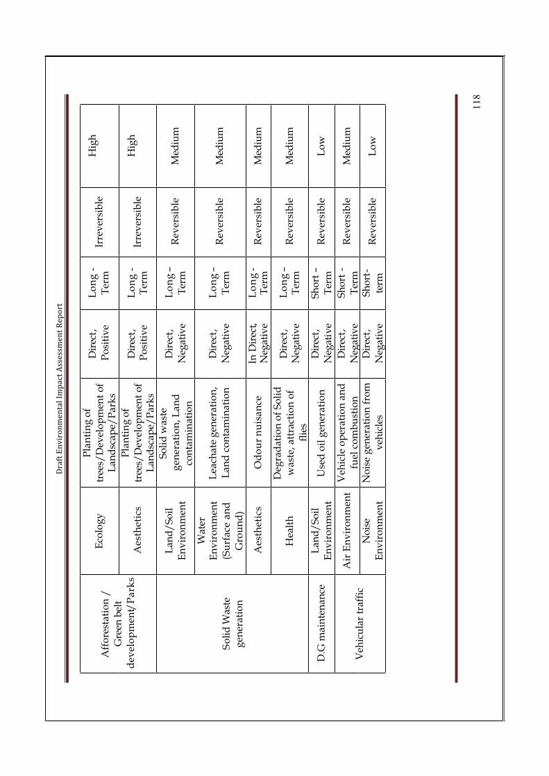
Dra
ft E
nv
iro
nm
en
tal
Imp
act
Ass
ess
me
nt
Re
po
rt
11
8
Eco
log
yP
lan
tin
g o
f
tree
s/D
evel
op
men
t o
f L
and
scap
e/P
ark
s
Dir
ect,
Po
siti
ve
Lo
ng
-
Ter
mIr
rev
ersi
ble
Hig
h
Aff
ore
stat
ion
/
Gre
en b
elt
dev
elo
pm
ent/
Pa
rks
Aes
thet
ics
Pla
nti
ng
of
tree
s/D
evel
op
men
t o
f L
and
scap
e/P
ark
s
Dir
ect,
Po
siti
ve
Lo
ng
-T
erm
Irre
ver
sib
leH
igh
Lan
d/
So
il
En
vir
on
men
t
So
lid
was
te
gen
era
tio
n, L
an
d
con
tam
inat
ion
Dir
ect,
Neg
ativ
e
Lo
ng
–
Ter
mR
ever
sib
leM
ediu
m
Wat
erE
nv
iro
nm
ent
(Su
rfa
ce a
nd
Gro
un
d)
Lea
chat
e g
ener
atio
n,
Lan
d c
on
tam
inat
ion
Dir
ect,
Neg
ativ
e
Lo
ng
–
Ter
mR
ever
sib
leM
ediu
m
Aes
thet
ics
Od
ou
r n
uis
an
ceIn
Dir
ect,
Neg
ativ
eL
on
g-
Ter
mR
ever
sib
leM
ediu
m
So
lid
Was
te
gen
erat
ion
Hea
lth
Deg
rad
atio
n o
f S
oli
d
was
te,
attr
acti
on
of
flie
s
Dir
ect,
Neg
ativ
eL
on
g–
Ter
mR
ever
sib
leM
ediu
m
D.G
mai
nte
nan
ceL
and
/S
oil
En
vir
on
men
tU
sed
oil
gen
erat
ion
Dir
ect,
Neg
ativ
e
Sh
ort
–
Ter
mR
ever
sib
leL
ow
Air
En
vir
on
men
tV
ehic
le o
per
atio
n a
nd
fuel
co
mb
ust
ion
Dir
ect,
Neg
ativ
e
Sh
ort
-
Ter
mR
ever
sib
leM
ediu
m
Veh
icu
lar
traf
fic
No
ise
En
vir
on
men
t
No
ise
gen
erat
ion
fro
m
veh
icle
s
Dir
ect,
Neg
ativ
e
Sh
ort
-
term
Rev
ersi
ble
Lo
w

Dra
ft E
nv
iro
nm
en
tal
Imp
act
Ass
ess
me
nt
Re
po
rt
11
9
Qu
alit
y o
f Lif
eS
oci
o-
Eco
no
mic
Em
plo
ym
ent
gen
erat
ion
,Qu
alit
y o
f li
fe,
In-f
low
of
fun
ds
in t
he
reg
ion
,
Incr
ease
in
ho
usi
ng
acc
om
mo
da
tio
n
InD
irec
t,P
osi
tiv
eL
on
g-
Ter
mIr
rev
ersi
ble
Hig
h
Sto
rm w
ater
Ru
n-o
ff
La
nd
En
vir
on
men
tF
loo
din
gD
irec
t,
Neg
ativ
e
Lo
ng
term
Rev
ersi
ble
Med
ium

Draft Environmental Impact Assessment Report
M/s Shree Ram Electrocast Pvt Ltd., 120
4.2 Impact on Environment during Construction Phase
This includes the following activities related to levelling of site, construction anderection of main plant structures and equipment.
4.2.1 Impact on Land use
The total available land with SREPL is 114.97 acres. Additional land of 25.42 Acres will be acquired through KIADB. The proposed plant area is more or less flat which require minimum levelling.
Under this project program there is need for additional process control rooms andworkmen rooms. The construction under this expansion program would bring certain immediate changes in the land use pattern of the proposed area as well as in thevicinity. There will be permanent change in the land use pattern of the existing scenario of land use. No demolition of existing structure will take place during the expansion phase. But these changes can cause any significant negative impacts. Temporary sites will be used for construction works or housing of construction workers.
In view of the country’s economic growth due to industrialization such extension projects are more advantages both economic and conservation of land point of views.
As it is an existing project, the construction activities would not attract a sizable labour population and the influx of population is minimal and likely to be associated with construction of temporary hutments is also minimal. The construction period envisaged for the plant is approximately 24 months. Any changes during the construction phase are temporary.
4.2.2 Impact on Soil
The proposed land is having flat profile; therefore the earthwork involved in levelling the land is very less. The maximum topsoil cover thickness at the plant site is about 1-m. The topsoil removed during the levelling will be stacked separately and will be used during the greenbelt development. Herbs and shrubs will be removed prior tocommencement of bulk earthwork. Removal of trees will be avoided as far as possible based on the construction plan. Medium trees size trees will be uprooted and planted in the designed green belt.
Greenbelt development program will start simultaneously along with civilconstructions.

Draft Environmental Impact Assessment Report
M/s Shree Ram Electrocast Pvt Ltd., 121
If the civil activities are not monitored properly the concrete and cement will fall haphazardly and will not project good aesthetic look, there by upper soil strata will be contaminated with concrete. Proper planning during construction period will minimize the upper soil contamination. So proper planning in civil activities will not cause any negative impact on the soil.
4.2.3 Impact on Air Quality
Impact of construction activities on air quality is a cause for concern mainly in the dry months due to settling of dust particles. The main sources of emission during theconstruction period are the movement of equipment at site and dust emitted during the levelling, grading, earthworks, foundation works and other construction relatedactivities. The dust emitted during the above mentioned activities depend upon the type of soil being excavated and the ambient humidity levels. The impact is likely to be for short duration and confined locally to the construction site itself. The composition of dust in this kind of operation is, however, mostly inorganic and non-toxic in nature.
Exhaust emissions from vehicles and equipment deployed during the construction phase also result in marginal increase in the levels of SO2, NOx, SPM, CO and unburnt hydrocarbons. It may, therefore, be deduced that construction activities may causechanges in the PM10 levels locally. The impact will, however, be reversible, marginal, and temporary in nature.
4.2.4 Impact on Water Quality
The construction water requirement will be met from Tungabhadra river water. Impact on water quality during construction phase may be due to sewage generated from the construction work force stationed at the site. As the construction being carried out on the flat terrain and relatively small area, the soil losses will be negligible. Further, the construction activities are more related to mechanical fabrication, assembly anderection, the need of water requirement will be small. Temporary sanitation facilities (soak pits/septic tanks) will be set up for disposal of sanitary sewage generated by the work force as per the prevailing labor laws. The overall impact on water environment during construction phase due to proposed plant is likely to be short term andinsignificant and they will be managed by providing drinking water facility andsanitation facilities at the site during construction phase.
4.2.5 Impact on Noise Levels
Heavy construction traffic for loading and unloading, fabrication and handling ofequipment and materials are likely to cause an increase in the ambient noise levels. The areas affected are those close to the site. However, there is no habitation within 1.0-kmradius area, no habitation to be affected due to noise. At the peak of the construction,

Draft Environmental Impact Assessment Report
M/s Shree Ram Electrocast Pvt Ltd., 122
marginal increase in noise levels is expected to occur but they are temporary. Thetypical noise levels of some construction equipment are given.
Table 4.4 Typical Noise Levels of Construction Equipment
Description Noise Levels dB (A)
Earth Movers
Front End Loaders 72-84
Backhoes 72-93
Tractors 76-96
Scrapers, Graders 80-93
Pavers 86-88
Trucks 82-94
Material Handlers
Concrete mixers 75-88
Concrete pumps 81-88
Cranes (movable) 75-86
Cranes (derrick) 86-88
Stationary Equipment
Pumps 69-71
Generators 71-82
Compressors 74-86
Source: US EPA, 1971, WSDOT
The peak noise levels from continuous construction activity may be about 90 dB (A). Since the populated areas are away. (>1.5 km) from the proposed site, the noise levels are considered to have insignificant impact. The noise control measures duringconstruction phase include provision of caps on the equipment and regularmaintenance of the equipment. Workers would be provided with earmuffs andearplugs.
Overall, the impact of noise generated on the environment is likely to be insignificant, reversible and localized in nature and mainly confined to the day hours.

Draft Environmental Impact Assessment Report
M/s Shree Ram Electrocast Pvt Ltd., 123
4.2.6 Impact on Terrestrial Ecology
The removal of herbaceous vegetation generally causes loosening of topsoil. The land available with SREPL is about 114.97 acres. Additional land to be acquired through KIADB is 65.13 Acres. However, such negative impacts would be reversible in topositive impacts by development of thick green belt and in a course of time that will develop as a sustainable ecosystem.
4.2.7 Impact on Aquatic Ecology
The construction of the plant is not likely to have any impact on aquatic eco-system, as there are no major surface water bodies in the immediate vicinity of the plant.
4.2.8 Demography and Socio-economics
As the proposed plant site lies in the existing plant premises, there are no persons who will be affected due to land acquisition and no rehabilitation is required.
During the construction period, there will be increase in floating population. Additional strain on civic amenities like road, transport, communication, drinking water, sanitation and other facilities will take place, to meet the work force requirement. The project will provide temporary employment of skilled and highly skilled manpower. Most of the people will be employees of contractors/sub-contractors.
The non-workers [including marginal workers] in the study area constitute about43.06%. This indicates the availability of sizeable manpower required for theconstruction activity.
• Most of the manpower deployed during the construction period will be from local area. During the construction phase there will be increased demand ofservices. These include hotels, lodges, public transport (including taxis), etc.There will also be ample opportunities for providing these services. In addition to the opportunity of getting employment as construction laborers, the localpopulation would also have employment opportunities in related serviceactivities like petty commercial establishments, small contracts/sub-contractsand supply of construction materials for buildings and ancillary infrastructures etc. Consequently, this may lead to economic upliftment of the area.
• The influx of population is very limited it is anticipated that there will be no social conflicts between the guest and host communities in the initial stages of development.
• The movement of work force to and from the place of work and the movement of vehicles carrying equipment and construction material is expected to increase the stress on the local transport and road network. However, considering the
Draft Environmental Impact Assessment Report
M/s Shree Ram Electrocast Pvt Ltd., 124
number of people deployed, the impact on road/traffic is marginal andtemporary.
• Labor Rate: As work on plant construction begins, the inflationary push willmanifest itself in increase in labor rate.
• Consumer Prices: Usually the local population will be affected by inflationarytrend sometime later, when prices of local services and produce, egg, fish,vegetables, milk, etc. start rising. This will happen only when a sizeable staff of the project and other associate companies settle permanently in the area.However any such rise in consumer prices is anticipated because the influx of population due to the project activities is minimal.
• Transport and Civil Construction: The transport companies would benefit from the construction of the plant.
• Services: The services like retail shops, banks, and automobile workshops; health care, etc. will expand in and near the proposed township.
• Employment: Large-scale influx of material and money tend to increase the employment opportunities.
• Literacy: The setting up of the proposed plant would increase literacy ratesmarginally.
• Traffic: The plant construction phase will also see a moderate increase in traffic.
• Development of Slums:. The contractors have to necessarily provide basicamenities like water supply, sanitation, electricity etc. at the labor camp tomaintain hygienic condition and aesthetics.
4.2.9 Public Expectation
Major occupation of the people in this area is agriculture. The overall income from agriculture is not constant and largely depends upon the climatic factors. Most of the unemployed literates prefer to work in any industry rather than farming or ownings to small land. The people in the area welcome the project, anticipating more jobs and more infrastructure facilities to the local people, provided that the industry will not cause any pollution in the nearby environment. More over being an economically backward area, the plant will have more positive impacts by creating direct or indirect employment.
4.3 Identification of Potential Impacts during Operational Phase
Both beneficial as well as potential adverse impacts may be expected on environment from any development project due to its various activities associated with theoperations. The impacts may be direct or indirect, short or long term and reversible or irreversible. However during the installation of expansion project, the size of the major civil activities are minimum and the impacts are of temporary. On the basis of the above analysis, the potential significant impacts on the environment from the proposed project are identified as below:
• Soil Quality & Topography and Climate;

Draft Environmental Impact Assessment Report
M/s Shree Ram Electrocast Pvt Ltd., 125
• Ambient Air Quality; Traffic
• Water Resources; Water Quality;• Noise Levels;
• Ecology; and Demography and Socio-economics.
4.3.1 Impact on Soil
The generation of solid waste from the proposed expansion project are the likelysources of negative impact on the soil characteristics. The negative impacts will beminimized by proper disposal of solid waste generated in the plant. The solid waste generated from the air pollution control equipment will be collected and disposed off in a scientific manner. The sludge generated from the sanitary waste treatment units will be organic in nature and will be used as manure for the green belt. This will not have any adverse impact on the soil quality. The fugitive dust from the plant duringoperation is likely to be deposited in the nearby areas. However, the proposed dust extraction and suppression measures at the source will significantly reduce thispossibility. Further, the proposed greenbelt comprising diversified species not onlyincreases the biomass, soil fertility, and productivity but also helps as pollution sinks and control of soil erosion. Hence, the likely impact on the soil characteristics will be minimal in terms of aerial spread and will not affect the sub-surface soil, as all precautions will beimplemented during the construction of the plant itself.
4.3.2 Topography and Climate
4.3.2.1 Impact on Topography
The major envisaged topographical changes would be due to the manmade structures like civil structures and including erection of stacks. The land available with SREPL is about 114.97 acres. Additional land to be acquired through KIADB is 65.13 Acres. The impact is not significant however; it will invite positive benefits in the form of land leveling and tree plantations in the plant vicinity.
4.3.2.2 Impact on Climate
The existing vegetation in the study area and the proposed green belt in the plantpremises will always have a cooling effect to offset any increase in temperature. The thermal pollution is only confined to small distance and the proposed greenbelt not only nullifies the thermal emissions but also it helps to keep surrounding ambient air cool.
4.3.3 Impact on Air Quality
The following table shows the emission pathways of pollution from the proposed plant
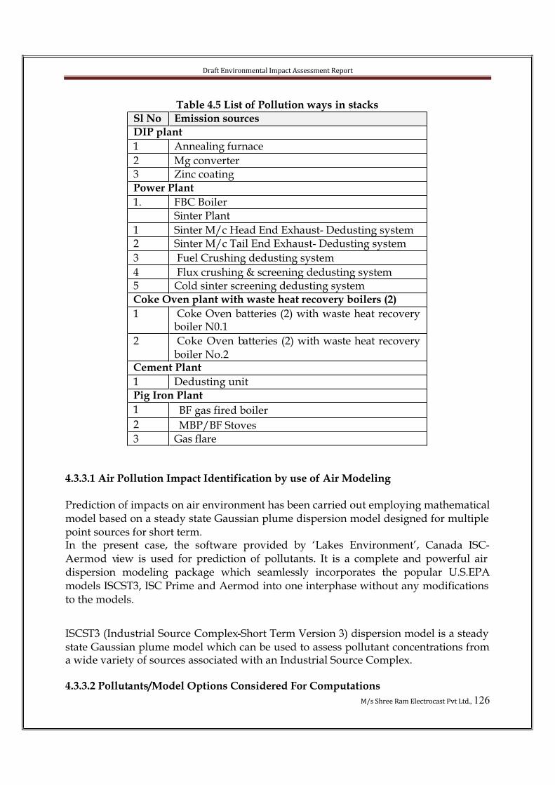
Draft Environmental Impact Assessment Report
M/s Shree Ram Electrocast Pvt Ltd., 126
Table 4.5 List of Pollution ways in stacks
Sl No Emission sources
DIP plant
1 Annealing furnace
2 Mg converter3 Zinc coatingPower Plant
1. FBC BoilerSinter Plant
1 Sinter M/c Head End Exhaust- Dedusting system2 Sinter M/c Tail End Exhaust- Dedusting system
3 Fuel Crushing dedusting system
4 Flux crushing & screening dedusting system5 Cold sinter screening dedusting systemCoke Oven plant with waste heat recovery boilers (2)
1 Coke Oven batteries (2) with waste heat recovery boiler N0.1
2 Coke Oven batteries (2) with waste heat recovery boiler No.2
Cement Plant
1 Dedusting unitPig Iron Plant
1 BF gas fired boiler
2 MBP/BF Stoves3 Gas flare
4.3.3.1 Air Pollution Impact Identification by use of Air Modeling
Prediction of impacts on air environment has been carried out employing mathematical model based on a steady state Gaussian plume dispersion model designed for multiple point sources for short term. In the present case, the software provided by ‘Lakes Environment’, Canada ISC-Aermod view is used for prediction of pollutants. It is a complete and powerful air dispersion modeling package which seamlessly incorporates the popular U.S.EPAmodels ISCST3, ISC Prime and Aermod into one interphase without any modifications to the models.
ISCST3 (Industrial Source Complex-Short Term Version 3) dispersion model is a steady state Gaussian plume model which can be used to assess pollutant concentrations from a wide variety of sources associated with an Industrial Source Complex.
4.3.3.2 Pollutants/Model Options Considered For Computations
Draft Environmental Impact Assessment Report
M/s Shree Ram Electrocast Pvt Ltd., 127
The model simulation deal with three major pollutants viz. Particulate Matter (PM10),Sulphur Dioxide (SO2) and Nitrogen dioxide (NO2) emitted from the proposed stack. The model options used for computation is as follows
• The plume rise is estimated by Briggs formulae, but the final rise is alwayslimited to that of the mixing layer;
• Stack tip down-wash is not considered;
• Buoyancy Induced Dispersion is used to describe the increase in plumedispersion during the ascension phase;
• Calms processing routine is used by default;
• Wind profile exponents is used by default, 'Irwin';• Flat terrain is used for computations;
• It is assumed that the pollutants do not undergo any physico-chemicaltransformation and that there is no pollutant removal by dry deposition;
• Washout by rain is not considered;
• Cartesian co-ordinate system has been used for computations; and
• The model computations have been done for 10-km with 1000-m interval.
4.3.3.3 Model Input Data
The proposed expansion plant will have 15 stacks. The details of stack emissions from plant are given below. The flue gas from two coke oven batteries will pass through one Waste heat recovery boiler and then through chimney. The flow of volume of air is calculated based on stack diameter, velocity and temperature. The emission rates are calculated based on sulphur and ash content in the fuel used. Apart from stack discharge details, field generated meteorological conditions such as anemometer height; pre-processed meteorological data (temperature, wind speed, direction, cloud cover etc) are also used as in put data. The height of the stack is calculated based on the sulphur dioxide and particulate emission rate and which ever more is used in modelcalculations. Based on the topography simple flat terrain is chosen. The site location is indicated in the form of latitude and longitude and Mean Sea Level (MSL). Total 10 km radius around site is chosen and x, y coordinators and receptors are given accordingly.
Emission data used for modeling is enclosed as annexure-3
Results of air quality modeling carried out to the proposed expansion plant is enclosed as Annexure-4
4.3.3.4 Fugitive Emissions
As the release height is less, the impacts of fugitive emissions are localized. Fugitive emission are predicted using following emission factors (USEPA emission factors).

Draft Environmental Impact Assessment Report
M/s Shree Ram Electrocast Pvt Ltd., 128
Table 4.6 Fugitive emission data
Sl.No.
Operation PM 2.5 PM 10
1 Near Blower House 112.0 266.02 Near Boiler House 146 345.0
3 Near RMHS 46.0 102.04 Near Workshop 325.0 125.0
5 Near Group Hopper 91.0 102.0
Fig 4.1 Dispersion of particulate matter
Fig 4.2 Dispersion of SO2

Draft Environmental Impact Assessment Report
M/s Shree Ram Electrocast Pvt Ltd., 129
Fig 4.3 Dispersion of NO2
Table 4.7 Summary of Air quality dispersion model:
SlNo
Pollutant NAAQStandards(µg/m3)
MaximumBaselineconcentration
(µg/m3)
MaximumIncrementalconcentration
(µg/m3)
Totalconcentration(µg/m3)
Remarks
1 Particulatematter
100 78.0 5.077 83.077 Theconcentrationis well
within thestandard.
2 SO2 80 5.6 1.567 7.167 Theconcentrationis well
within thestandard.
3 NO2 80 15.3 0.943 16.24 Theconcentration
is wellwithin thestandard.

Draft Environmental Impact Assessment Report
M/s Shree Ram Electrocast Pvt Ltd., 130
4.3.4 Impact on Traffic
The product generated in the existing plant being used for the proposed plantproduction. Hence there is only insignificant increase in the existing traffic levels. The raw material and finished products of the proposed plant will be transported by road.

Draft Environmental Impact Assessment Report
M/s Shree Ram Electrocast Pvt Ltd., 131
Existing Traffic loadTable 4.8 Existing traffic
MAIN APPROACH ROAD- TOWARDS HATCHOLLI
MAIN APPROCH ROAD TOWARDSSIRUGUPPA
Total
VEHICLES3
WH
EE
LE
R
2 W
HE
EL
ER
CY
CL
ES
VEHICLES
3 W
HE
EL
ER
2 W
HE
EL
ER
CY
CL
ES
VEHICLES
3 W
HE
EL
ER
2 W
HE
EL
ER
CY
CL
ES
TIME(HRS)
HEAVY MEDIUM LIGHT HEAVY MEDIUM LIGHT HEAVY MEDIUM LIGHT
00.30-
01.302 0 0 0 3 0 1 0 0 0 0 0
3 0 0 0 3 0
01.30-
02.301 0 0 0 4 0 0 0 0 0 0 0
1 0 0 0 4 0
02.30-03.30
2 1 0 0 3 0 1 0 0 1 0 03 1 0 1 3 0
03.30-04.30
0 2 1 1 4 3 2 1 3 0 2 02 3 4 1 6 3
04.30-05.30
1 0 2 2 3 1 1 0 2 0 1 12 0 4 2 4 2
05.30-06.30
3 1 1 1 4 1 2 2 1 2 5 35 3 2 3 9 4
06.30-
07.300 3 3 3 5 2 1 3 4 3 4 2
1 6 7 6 9 4
07.30-08.30
4 2 2 2 8 4 3 7 6 1 8 57 9 8 3 16 9
08.30-09.30
1 4 4 5 7 5 2 5 8 3 12 33 9 12 8 19 8
09.30-10.30
2 5 5 4 13 3 4 4 3 4 6 46 9 8 8 19 7
10.30-11.30
5 3 7 7 9 2 7 2 2 2 3 212 5 9 9 12 4
11.30-
12.306 8 5 5 8 4 5 8 7 1 5 4
11 16 12 6 13 8
12.30-
13.302 7 9 9 10 1 4 6 5 3 4 2
6 13 14 12 14 3
13.30-14.30
1 4 3 3 11 3 2 2 9 4 3 33 6 12 7 14 6
14.30-15.30
3 6 4 4 8 5 2 4 13 2 7 15 10 17 6 15 6
15.30-16.30
0 4 5 5 9 2 1 5 4 0 8 01 9 9 5 17 2
16.30-17.30
0 2 2 2 6 5 0 2 5 1 10 20 4 7 3 16 7
17.30-
18.302 1 1 1 8 7 1 3 4 4 4 1
3 4 5 5 12 8
18.30-
19.301 0 3 3 9 4 3 7 3 2 3 3
4 7 6 5 12 7
19.30-20.30
0 0 3 3 4 2 3 2 3 4 5 13 2 6 7 9 3
20.30-21.30
2 3 2 2 5 1 4 1 0 1 3 06 4 2 3 8 1
21.30-22.30
4 2 0 0 2 0 1 0 2 0 1 05 2 2 0 3 0
22.30-23.30
1 2 1 1 0 1 1 1 0 0 0 12 3 1 1 0 2
23.30-
00.300 0 1 1 0 0 0 0 1 1 1 0
0 0 2 2 1 0
TOTAL 43 60 64 64 143 56 51 65 85 39 95 38 94 125 149 103 238 94
Avg. 2 2 3 3 6 2 2 3 3 1 4 1 4 5 6 4 10 4
Max. 6 8 9 9 13 7 7 8 13 4 12 5 12 16 17 12 19 9
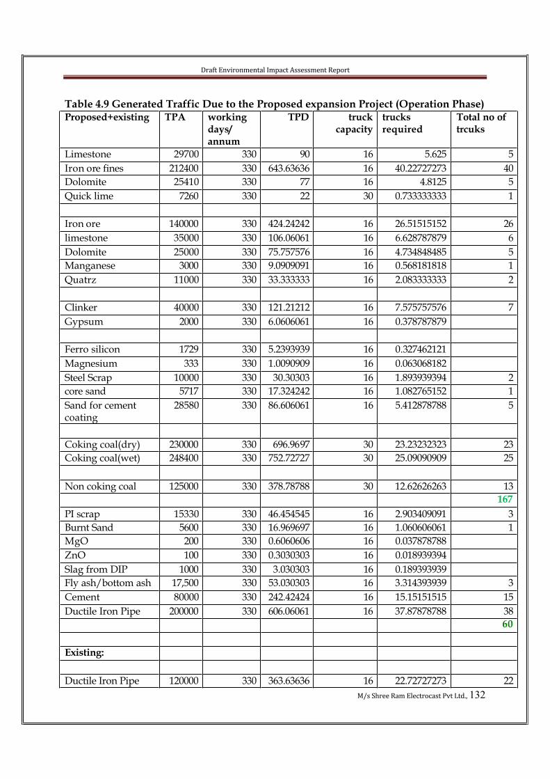
Draft Environmental Impact Assessment Report
M/s Shree Ram Electrocast Pvt Ltd., 132
Table 4.9 Generated Traffic Due to the Proposed expansion Project (Operation Phase)Proposed+existing TPA working
days/annum
TPD truckcapacity
trucksrequired
Total no of trcuks
Limestone 29700 330 90 16 5.625 5
Iron ore fines 212400 330 643.63636 16 40.22727273 40
Dolomite 25410 330 77 16 4.8125 5
Quick lime 7260 330 22 30 0.733333333 1
Iron ore 140000 330 424.24242 16 26.51515152 26
limestone 35000 330 106.06061 16 6.628787879 6
Dolomite 25000 330 75.757576 16 4.734848485 5
Manganese 3000 330 9.0909091 16 0.568181818 1
Quatrz 11000 330 33.333333 16 2.083333333 2
Clinker 40000 330 121.21212 16 7.575757576 7
Gypsum 2000 330 6.0606061 16 0.378787879
Ferro silicon 1729 330 5.2393939 16 0.327462121
Magnesium 333 330 1.0090909 16 0.063068182
Steel Scrap 10000 330 30.30303 16 1.893939394 2
core sand 5717 330 17.324242 16 1.082765152 1
Sand for cement coating
28580 330 86.606061 16 5.412878788 5
Coking coal(dry) 230000 330 696.9697 30 23.23232323 23
Coking coal(wet) 248400 330 752.72727 30 25.09090909 25
Non coking coal 125000 330 378.78788 30 12.62626263 13
167
PI scrap 15330 330 46.454545 16 2.903409091 3
Burnt Sand 5600 330 16.969697 16 1.060606061 1
MgO 200 330 0.6060606 16 0.037878788
ZnO 100 330 0.3030303 16 0.018939394
Slag from DIP 1000 330 3.030303 16 0.189393939
Fly ash/bottom ash 17,500 330 53.030303 16 3.314393939 3
Cement 80000 330 242.42424 16 15.15151515 15
Ductile Iron Pipe 200000 330 606.06061 16 37.87878788 38
60
Existing:
Ductile Iron Pipe 120000 330 363.63636 16 22.72727273 22
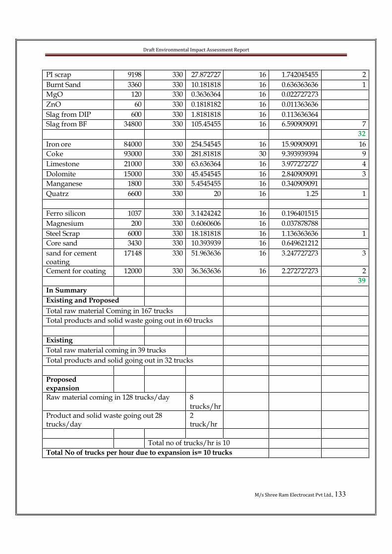
Draft Environmental Impact Assessment Report
M/s Shree Ram Electrocast Pvt Ltd., 133
PI scrap 9198 330 27.872727 16 1.742045455 2
Burnt Sand 3360 330 10.181818 16 0.636363636 1
MgO 120 330 0.3636364 16 0.022727273
ZnO 60 330 0.1818182 16 0.011363636
Slag from DIP 600 330 1.8181818 16 0.113636364
Slag from BF 34800 330 105.45455 16 6.590909091 7
32
Iron ore 84000 330 254.54545 16 15.90909091 16
Coke 93000 330 281.81818 30 9.393939394 9
Limestone 21000 330 63.636364 16 3.977272727 4
Dolomite 15000 330 45.454545 16 2.840909091 3
Manganese 1800 330 5.4545455 16 0.340909091
Quatrz 6600 330 20 16 1.25 1
Ferro silicon 1037 330 3.1424242 16 0.196401515
Magnesium 200 330 0.6060606 16 0.037878788
Steel Scrap 6000 330 18.181818 16 1.136363636 1
Core sand 3430 330 10.393939 16 0.649621212
sand for cement coating
17148 330 51.963636 16 3.247727273 3
Cement for coating 12000 330 36.363636 16 2.272727273 2
39
In Summary
Existing and Proposed
Total raw material Coming in 167 trucks
Total products and solid waste going out in 60 trucks
Existing
Total raw material coming in 39 trucks
Total products and solid going out in 32 trucks
Proposedexpansion
Raw material coming in 128 trucks/day 8
trucks/hr
Product and solid waste going out 28 trucks/day
2truck/hr
Total no of trucks/hr is 10
Total No of trucks per hour due to expansion is= 10 trucks
Draft Environmental Impact Assessment Report
M/s Shree Ram Electrocast Pvt Ltd., 134
It is clear from the above table that total number of trucks per hour is 10. Hence the impact on traffic is minimum.
Internal Transportation
Hot metal to pipe plant will be transported on a track by car-mounted ladle, which will be moved by a winch. Pig casting machine is adjacent to the blast furnace and the hot metal ladle will be moved by an overhead crane. There will be transportation of spare parts and consumables from stores and repair shops to respective departments and transportation of spare parts for repair-to-repair shops. This will be done by roadvehicles. Steel scrap and ferro silicon to pipe plant will be also moved by internal road vehicles.
4.3.5 Impact on Water Resources
Water requirement can be met through the current allotted water from TungabhadraRiver, which is 1.8 km from plant site. Use of water for industrial purpose causesnegative impact on the environment. The selected process is eco-friendly. Water will be recirculated and reused and there is zero discharge out side the plant premises. The proponent is going for rain water harvesting which will also be used in development of green belt. Recharge pits are also proposed to improve the ground water potential of the area. The development of green belt improves the moist conditions in the soil and control thermal radiation.
4.3.6 Impact on Water Quality
The water system will be of re-circulating type and no process wastewater will bedischarged. The entire process water requirement is kept in closed circuit and noprocess wastewater is discharged out side the premises. The clean water after the treatment of the blow down water will be reused in dust suppression on roads, fugitive emission suppression in raw material handling area, plantation etc.
Domestic effluents from the various buildings / sheds of the plant are conveyedthrough separate sewer line to STP of capacity 50 KLD. The treated water from STP will be used for greenbelt development
There will not be any wastewater generation from the proposed DIP plant.
4.3.7 Impact of solid waste
The solid waste generated in plants are listed below:

Draft Environmental Impact Assessment Report
M/s Shree Ram Electrocast Pvt Ltd., 135
Table 4.10 Solid waste generated from different operations (after expansion)
Pig iron plant Iron ore fines (97800 TPA)
Coke fines (11000 TPA) B.F.Slag (58000 TPA) GCP dust (6720 TPA)GCP sludge (5430 TPA)
P.I. Scrap (15330 TPA)
Used in sinter plant
Used in sinter plant Used in cement grinding plant Used in sinter plant Used in sinter plant
Sold out
DIP PLANT200,000TPA
Burnt sand generated in casting
section (5600 TPA)MgO (200 TPA)ZnO (100 TPA )Slag (1000 TPA)
Stored in the dump yard. Can be
used for land fillingSold out to approved vendors. Sold out to approved reprocessorsUsed for land filling
Metcoke plant Coke fines (5000 TPA) Will be used in sinter plant
Power Plant Coal ash/Fly ash (17500 TPA) Will be sold out
Sinter plant Sinter fines (6000) TPADust from ESP (5200 TPA)
Circulated backCirculated back
Slag Cementgrinding plant
Nil
4.3.8 Impact on Noise LevelsDuring the operational phase, noise will be generated from the DG set, crushers,turbogenerators, vehicles movement, and general noise characteristic of proposedindustry. Noise generation is also noticed from the blowing station, compressed air station. The DG set room will be isolated from the outside environment and proper acoustic arrangements will be made to control the noise generated from the rooms. Plant and equipment will be selected restricting the noise pollution within thepermissible limits. Silencers and soundproof insulation/cover will be provided tocontrol the noise pollution.
4.3.9 Impact on EcologyThe impacts on natural vegetation and species diversity will remain unaffected due to the expansion of plant. The plant is already in existing. There will be few tree cuttingand shrub removal will take place. Wherever possibility is there, the entire tree will be uprooted and planted at different place. The proposed green belt development scheme will enhance the biomass and leads to sustainable development. The green belt willenrich soil organic matter thereby nitrogen. It will help as noise barrier. Green beltcontrol temperature and keep the surroundings cool. It will attract avifauna and create

Draft Environmental Impact Assessment Report
M/s Shree Ram Electrocast Pvt Ltd., 136
suitable habitat to micro flora and fauna. The green belt will help as a sink to dust and gaseous pollutants. On the whole it has a positive impact on the environment.
There are no wild life sanctuaries with in the study zone. Forest is located at a distance of 4 km in the western direction. The released pollutants get diffused and get diluted before it reaches to the ground layer. The impact on flora is insignificant.
As there are no major leveling activities no impact on existing landscape is anticipated. The development of green belt will attract avifauna.
4.3.10 Socio-EconomicsThe impacts of the proposed expansion would begin to be felt with the start-up of the operational activities.
• The present trend of out migration for employment is likely to reduce due to better economic opportunities available in the area;
• The plant will result in considerable growth of service sector and will alsogenerate new industrial and business opportunities in the area. The ancillary facilities, would act, as an active nucleus for new industries and businessactivities, a shift of population towards this center and peripheral area is likely to occur.
The socio-economic impacts discussed in the construction phase of the proposed plant will also be manifested during the operation phase in the following manner.
• Increase in consumer prices of indigenous produce and services, land prices, house rent rates and labour prices.
• Some increase in services catering to the additional population will occur due to the setting up of the plant.
• Influx of persons with higher spending power and different socio-culturalbackground will improve the socio-cultural environment of the area, though occasional tension as a result of this influx cannot be totally ruled out.
• Improvement in transport, communication, health and educational services.• Increase in employment due to large flow of financial and material resources
through increased business, trade commerce and service sector.
Additional land will be acquired through KIADB and the land is not inhabited. Hence rehabitation is not required.
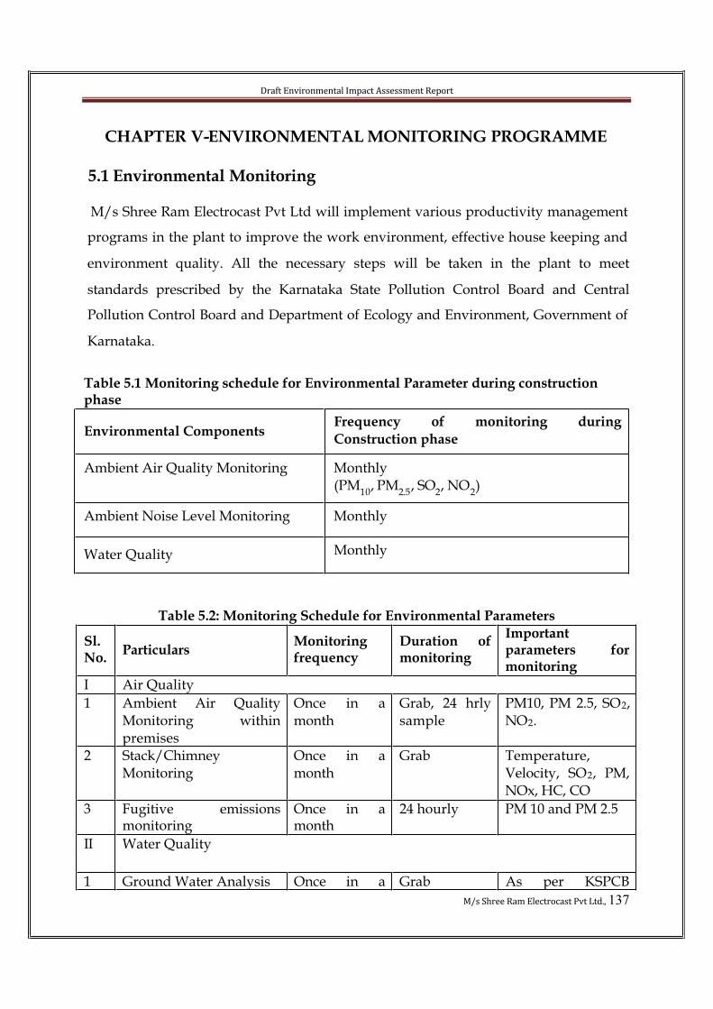
Draft Environmental Impact Assessment Report
M/s Shree Ram Electrocast Pvt Ltd., 137
CHAPTER V-ENVIRONMENTAL MONITORING PROGRAMME
5.1 Environmental Monitoring
M/s Shree Ram Electrocast Pvt Ltd will implement various productivity management
programs in the plant to improve the work environment, effective house keeping and
environment quality. All the necessary steps will be taken in the plant to meet
standards prescribed by the Karnataka State Pollution Control Board and Central
Pollution Control Board and Department of Ecology and Environment, Government of
Karnataka.
Table 5.1 Monitoring schedule for Environmental Parameter during construction phase
Environmental ComponentsFrequency of monitoring during
Construction phase
Ambient Air Quality Monitoring Monthly(PM
10, PM
2.5, SO
2, NO
2)
Ambient Noise Level Monitoring Monthly
Water Quality Monthly
Table 5.2: Monitoring Schedule for Environmental Parameters
Sl.No.
ParticularsMonitoringfrequency
Duration ofmonitoring
Importantparameters formonitoring
I Air Quality
1 Ambient Air QualityMonitoring withinpremises
Once in amonth
Grab, 24 hrlysample
PM10, PM 2.5, SO2,NO2.
2 Stack/ChimneyMonitoring
Once in amonth
Grab Temperature,Velocity, SO2, PM,NOx, HC, CO
3 Fugitive emissionsmonitoring
Once in amonth
24 hourly PM 10 and PM 2.5
II Water Quality
1 Ground Water Analysis Once in a Grab As per KSPCB
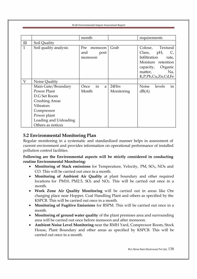
Draft Environmental Impact Assessment Report
M/s Shree Ram Electrocast Pvt Ltd., 138
month requirements
III Soil Quality1 Soil quality analysis Pre monsoon
and postmonsoon
Grab Colour, TexturalClass, pH, C,Infiltration rate,Moisture retentioncapacity, Organicmatter, Na,K,P,Pb,Cu,Zn,Cd,Fe
V Noise QualityMain Gate/BoundaryPower PlantD.G Set RoomCrushing AreasVibratorsCompressorPower plantLoading and UnloadingOthers as notices
Once in aMonth
24HrsMonitoring
Noise levels indB(A)
5.2 Environmental Monitoring PlanRegular monitoring in a systematic and standardized manner helps in assessment of current environment and provides information on operational performance of installed pollution control facilities.
Following are the Environmental aspects will be strictly considered in conducting
routine Environmental Monitoring:
• Monitoring of Stack emissions for Temperature, Velocity, PM, SO2, NOx and
CO. This will be carried out once in a month.• Monitoring of Ambient Air Quality at plant boundary and other required
locations for PM10, PM2.5, SO2 and NO2. This will be carried out once in amonth.
• Work Zone Air Quality Monitoring will be carried out in areas like Orecharging place near Hopper, Coal Handling Plant and others as specified by the KSPCB. This will be carried out once in a month.
• Monitoring of Fugitive Emissions for RSPM. This will be carried out once in a
month.• Monitoring of ground water quality of the plant premises area and surrounding
area will be carried out once before monsoon and after monsoon.• Ambient Noise Level Monitoring near the RMH Yard, Compressor Room, Stock
House, Plant Boundary and other areas as specified by KSPCB. This will becarried out once in a month.
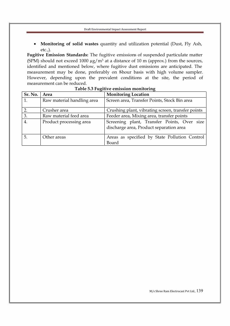
Draft Environmental Impact Assessment Report
M/s Shree Ram Electrocast Pvt Ltd., 139
• Monitoring of solid wastes quantity and utilization potential (Dust, Fly Ash,
etc.,).Fugitive Emission Standards: The fugitive emissions of suspended particulate matter
(SPM) should not exceed 1000 µg/m3 at a distance of 10 m (approx.) from the sources, identified and mentioned below, where fugitive dust emissions are anticipated. The measurement may be done, preferably on 8-hour basis with high volume sampler.However, depending upon the prevalent conditions at the site, the period ofmeasurement can be reduced.
Table 5.3 Fugitive emission monitoring
Sr. No. Area Monitoring Location
1. Raw material handling area Screen area, Transfer Points, Stock Bin area
2. Crusher area Crushing plant, vibrating screen, transfer points 3. Raw material feed area Feeder area, Mixing area, transfer points
4. Product processing area Screening plant, Transfer Points, Over sizedischarge area, Product separation area
5. Other areas Areas as specified by State Pollution ControlBoard

Draft Environmental Impact Assessment Report
M/s Shree Ram Electrocast Pvt Ltd., 140
CHAPTER-VIOCCUPATIONAL HEALTH AND SAFETY AND DISASTER
MANAGEMENT PLAN6.0 Introduction Rapid development has posed wide-ranging hazards threatening safety and health of people. Accidents may adversely affect the environment and the people living in the vicinity. These accidents can be minimized to a great extent by proper procedures,handling and training. But it may be difficult to reach zero risk or absolute safety level. Whenever such incidents do occur in order to prevent loss of lives and damage to property, it becomes necessary to take immediate steps to control the situation. This can be achieved through a planned advance preparation to face such a situation with respect to both on site and off site emergencies.
6.1 Quality, Environment and Occupational Health and Safety Policy
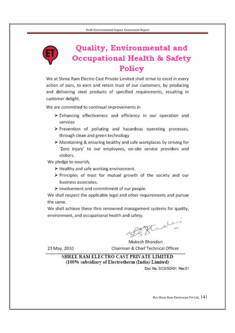
Draft Environmental Impact Assessment Report
M/s Shree Ram Electrocast Pvt Ltd., 141
Draft Environmental Impact Assessment Report
M/s Shree Ram Electrocast Pvt Ltd., 142
Hazard: Anything (e.g. condition, situation, practice, behavior) that has the potential to
cause harm, including injury, disease, death, environmental or property and equipmentdamage.Hazard Identification: This is the process of examining each work area and work task
for the purpose of identifying all the hazards which are “inherent in the job”. Work areas include but are not limited to machine workshops, laboratories, office areas,agricultural and horticultural environments, stores and transport, maintenance. Tasks can include (but may not be limited to) industrial equipment, hazardous substances and/or dangerous goods, driving a vehicle, dealing with emergency situations,construction.Risk: The likelihood or probability that a hazardous event (with a given outcome or
consequence) will occur. Risk Assessment: Is defined as the process of assessing the risks associated with each of the hazards identified so that appropriate control measures can be implemented based on the probability, i.e. likelihood that harm, injury or ill health may occur and how severe the consequences of exposure might be.
6.2 HAZARD CHART
Fig 6.1 Hazard Chart
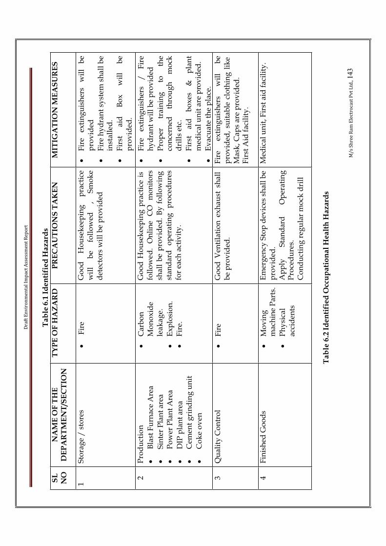
Dra
ft E
nv
iro
nm
en
tal
Imp
act
Ass
ess
me
nt
Re
po
rt
M/
s S
hre
e R
am
Ele
ctro
cast
Pv
t L
td.,143
Ta
ble
6.1
Id
en
tifi
ed
Ha
za
rds
SL
NO
NA
ME
OF
TH
E
DE
PA
RT
ME
NT
/SE
CT
ION
TY
PE
OF
HA
ZA
RD
PR
EC
AU
TIO
NS
TA
KE
NM
ITIG
AT
ION
ME
AS
UR
ES
1S
tora
ge
/ s
tore
s•
Fir
eG
oo
d
Ho
use
kee
pin
g
pra
ctic
ew
ill
be
foll
ow
ed
, S
mo
ke
det
ecto
rsw
ill
be
pro
vid
ed
•F
ire
exti
ng
uis
her
s w
ill
be
pro
vid
ed
•F
ire
hy
dra
nt
syst
em s
ha
ll b
e in
sta
lled
.
•F
irst
ai
d
Bo
x
wil
l b
ep
rov
ided
.
2P
rod
uct
ion
•B
last
Fu
rnac
e A
rea
•S
inte
r P
lan
t ar
ea•
Po
wer
Pla
nt
Are
a
•D
IP p
lan
t ar
ea•
Cem
ent
gri
nd
ing
un
it
•C
ok
e o
ven
•C
arb
on
Mo
no
xid
ele
ak
ag
e.
•E
xp
losi
on
.•
Fir
e.
Go
od
Ho
use
kee
pin
g p
ract
ice
is
foll
ow
ed
. O
nli
ne
CO
m
on
ito
rssh
all
be
pro
vid
ed.
By
fo
llo
win
g
stan
dar
d
op
erat
ing
p
roce
du
res
for
each
act
ivit
y.
•F
ire
exti
ng
uis
her
s /
F
ire
hy
dra
nt
wil
l b
e p
rov
ided
•P
rop
er
trai
nin
g
to
the
con
cern
ed
thro
ug
h
mo
ckd
rill
s et
c.
•F
irst
ai
d
bo
xes
&
p
lan
tm
edic
al
un
it a
re p
rov
ided
.
•E
vac
uat
e th
e p
lace
.3
Qu
alit
y C
on
tro
l•
Fir
eG
oo
d V
enti
lati
on
ex
hau
st s
hal
l b
e p
rov
ided
.F
ire
exti
ng
uis
her
s w
ill
be
pro
vid
ed,
suit
able
clo
thin
g l
ike
Mas
k, C
aps
are
pro
vid
ed.
Fir
st A
id f
acil
ity
.
4F
inis
hed
Go
od
s•
Mo
vin
gm
ach
ine
Par
ts.
•P
hy
sica
lac
cid
ents
Em
erg
ency
Sto
p d
evic
es s
hal
l b
e p
rov
ided
.A
pp
ly
Sta
nd
ard
O
per
atin
gP
roce
du
res.
Co
nd
uct
ing
reg
ula
r m
ock
dri
ll
Med
ical
un
it, F
irst
aid
fac
ilit
y.
Ta
ble
6.2
Id
en
tifi
ed
Occ
up
ati
on
al
He
alt
h H
az
ard
s

Dra
ft E
nv
iro
nm
en
tal
Imp
act
Ass
ess
me
nt
Re
po
rt
M/
s S
hre
e R
am
Ele
ctro
cast
Pv
t L
td.,144
Ty
pe
of
Ha
za
rdA
reas
Pre
ven
tiv
e /
Mit
igati
on
measu
res
Du
stR
aw m
ater
ial
han
dli
ng
&
sto
rag
e y
ard
Wil
l b
e tr
ansp
ort
ed i
n t
he
tru
cks
wit
h t
arp
ual
in c
ov
ers.
En
vis
aged
to
in
stal
l a
tru
ck t
iple
r. W
ater
sp
rin
kle
rs i
n t
he
yar
d.
Co
ver
ed c
on
vey
or
bel
ts f
or
RM
fe
edin
g
to
RM
HS
b
un
ker
s as
wel
l to
B
F.
Pn
eum
atic
co
nv
eyo
r fo
r d
ust
han
dli
ng
fr
om
D
ry
GC
P
to
Sin
ter.
P
rov
idin
g
per
son
nel
p
rote
ctiv
eeq
uip
men
ts
lik
e re
spir
ato
rs,
cap
s,
apro
ns.
D
evel
op
men
t o
f g
reen
ary
al
lar
ou
nd
th
e y
ard
. Dev
elo
pin
g R
oad
s, a
shp
hal
tin
g e
tc.
No
ise
Blo
wer
ho
use
,
ID
fan
h
ou
se,
Tu
rbin
e h
all
, A
irco
mp
ress
or
ho
use
, DG
&P
um
p h
ou
ses.
Sel
ecti
on
o
f eq
uip
men
ts
con
firm
ing
to
st
and
ard
s.
i.e.
<
90
dB
A
at
1 m
trd
ista
nce
. A
ll t
hes
e ar
eas
shal
l b
e u
nm
ann
ed d
ue
to h
igh
lev
el a
uto
mat
ion
. S
uit
able
Ear
mu
ffs
wil
l p
rov
ided
to
th
e w
ork
ers
du
rin
g i
nsp
ecti
on
s.G
reen
bel
t co
rrid
or
wil
l b
e d
evel
op
ed a
lon
g t
he
per
iph
ery
of
the
pla
nt.
Ex
trem
e H
eat
Cas
t h
ou
se,
Pig
C
asti
ng
Mac
hin
e,
Sin
teri
ng
pla
tfo
rm,S
team
pip
ing
Pro
vid
ing
pro
per
PP
E l
ike
leg
gau
rds
wit
h s
ho
es,
Fac
e sh
eild
, le
ath
er h
and
g
lou
se,
Lea
ther
A
pro
ns,
hel
met
s et
c.
Th
erm
al
insu
lati
on
fo
r st
eam
li
ne.
Pro
vid
ing
fan
s, p
erso
nn
el c
oo
lin
g d
evic
es, w
ater
sh
ow
ers
etc.
BF
Gas
- C
OB
F T
op
, S
tov
e, G
CP
, C
ast
ho
use
, S
inte
r p
lat
form
,B
oil
er.
On
lin
e g
as d
etec
tor
syst
ems
shal
l b
e in
stal
led
in
ad
dit
ion
to
po
rtab
le C
Om
on
ito
rs. O
2 m
ask
s &
kit
s sh
all
be
pro
vid
ed.
No
ise
Blo
wer
ho
use
,
ID
fan
h
ou
se,
Tu
rbin
e h
all,
A
irco
mp
ress
or
ho
use
, DG
&P
um
p h
ou
ses.
Sel
ecti
on
o
f eq
uip
men
ts
con
firm
ing
to
st
and
ard
s.
i.e.
<
90
dB
A
at
1 m
trd
ista
nce
. A
ll t
hes
e ar
eas
shal
l b
e u
nm
ann
ed d
ue
to h
igh
lev
el a
uto
mat
ion
. S
uit
able
Ear
mu
ffs
wil
l p
rov
ided
to
th
e w
ork
ers
du
rin
g i
nsp
ecti
on
s.G
reen
bel
t co
rrid
or
wil
l b
e d
evel
op
ed a
lon
g t
he
per
iph
ery
of
the
pla
nt.
Ta
ble
6.3
Pre
lim
ina
ry H
az
ard
An
aly
sis
for
Pro
cess
an
d S
tora
ge
Are
as
Eq
uip
me
nt
Pro
cess
Po
ten
tial
Haz
ard
Pro
vis
ion
BF
Red
uct
ion
of
Iro
n O
reE
xp
losi
on
, Gas
lea
kag
e –
air
po
llu
tio
nG
as l
eak
age
det
ecti
on
sy
stem
, Str
ict
foll
ow
up
of
Std
Op
erat
ing
Pra
ctic
es
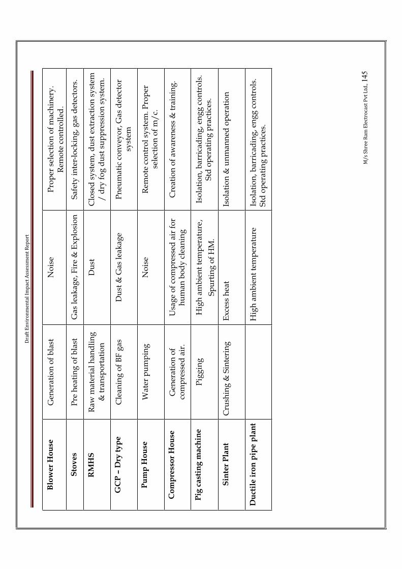
Dra
ft E
nv
iro
nm
en
tal
Imp
act
Ass
ess
me
nt
Re
po
rt
M/
s S
hre
e R
am
Ele
ctro
cast
Pv
t L
td.,145
Blo
wer
Ho
use
Gen
erat
ion
of
bla
stN
ois
eP
rop
er s
elec
tio
n o
f m
ach
iner
y.
Rem
ote
co
ntr
oll
ed.
Sto
ve
sP
re h
eati
ng
of
bla
stG
as l
eak
age,
Fir
e &
Ex
plo
sio
nS
afet
y i
nte
r-lo
ckin
g, g
as d
etec
tors
.
RM
HS
Raw
mat
eria
l h
and
lin
g
& t
ran
spo
rtat
ion
Du
stC
lose
d s
yst
em, d
ust
ex
trac
tio
n s
yst
em
/ d
ry f
og
du
st s
up
pre
ssio
n s
yst
em.
GC
P–
Dry
ty
pe
Cle
anin
g o
f B
F g
asD
ust
& G
as l
eak
age
Pn
eum
atic
co
nv
eyo
r, G
as d
etec
tor
syst
em
Pu
mp
Ho
use
Wat
er p
um
pin
gN
ois
eR
emo
te c
on
tro
l sy
stem
. Pro
per
se
lect
ion
of
m/
c.
Co
mp
ress
or
Ho
use
Gen
erat
ion
of
com
pre
ssed
air
.U
sag
e o
f co
mp
ress
ed a
ir f
or
hu
man
bo
dy
cle
anin
gC
reat
ion
of
awar
enes
s &
tra
inin
g.
Pig
cast
ing
mach
ine
Pig
gin
gH
igh
am
bie
nt
tem
per
atu
re,
Sp
urt
ing
of
HM
.
Iso
lati
on
, bar
rica
din
g, e
ng
g c
on
tro
ls.
Std
op
erat
ing
pra
ctic
es.
Sin
ter
Pla
nt
Cru
shin
g &
Sin
teri
ng
Ex
cess
hea
tIs
ola
tio
n &
un
man
ned
op
erat
ion
Du
ctil
e i
ron
pip
e p
lan
tH
igh
am
bie
nt
tem
per
atu
reIs
ola
tio
n, b
arri
cad
ing
, en
gg
co
ntr
ols
. S
td o
per
atin
g p
ract
ices
.
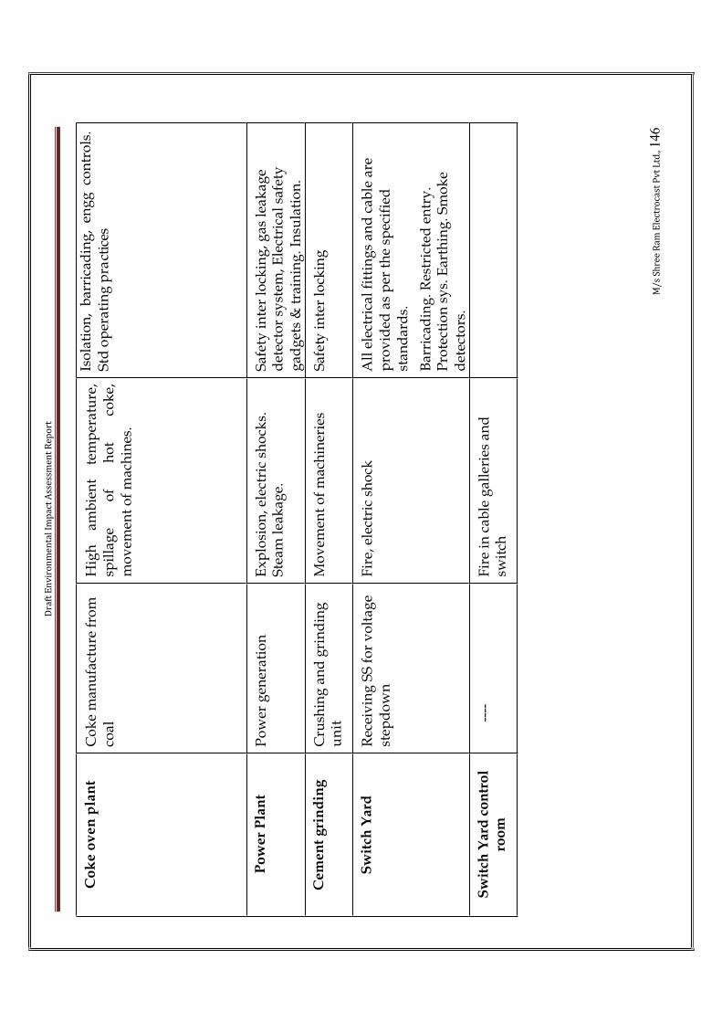
Dra
ft E
nv
iro
nm
en
tal
Imp
act
Ass
ess
me
nt
Re
po
rt
M/
s S
hre
e R
am
Ele
ctro
cast
Pv
t L
td.,146
Co
ke
ov
en
pla
nt
Co
ke
man
ufa
ctu
re f
rom
co
al
Hig
h
amb
ien
t te
mp
erat
ure
,sp
illa
ge
of
ho
t co
ke,
mo
vem
ent
of
mac
hin
es.
Iso
lati
on
, b
arri
cad
ing
, en
gg
co
ntr
ols
. S
td o
per
ati
ng
pra
ctic
es
Po
we
r P
lan
tP
ow
er g
ener
atio
nE
xp
losi
on
, ele
ctri
c sh
ock
s.
Ste
am l
eak
age.
Saf
ety
in
ter
lock
ing
, gas
lea
kag
e d
etec
tor
syst
em, E
lect
rica
l sa
fety
g
adg
ets
& t
rain
ing
. In
sula
tio
n.
Ce
me
nt
gri
nd
ing
Cru
shin
g a
nd
gri
nd
ing
u
nit
Mo
vem
ent
of
mac
hin
erie
s S
afet
y i
nte
r lo
ckin
g
Sw
itch
Yard
Rec
eiv
ing
SS
fo
r v
olt
age
step
do
wn
Fir
e, e
lect
ric
sho
ckA
ll e
lect
rica
l fi
ttin
gs
and
cab
le a
re
pro
vid
ed a
s p
er t
he
spec
ifie
d
stan
dar
ds.
Bar
rica
din
g. R
estr
icte
d e
ntr
y.
Pro
tect
ion
sy
s. E
arth
ing
. Sm
ok
e d
etec
tors
.
Sw
itch
Yard
co
ntr
ol
roo
m--
--F
ire
in c
able
gal
leri
es a
nd
sw
itch

Draft Environmental Impact Assessment Report
M/s Shree Ram Electrocast Pvt Ltd., 147
The environmental risk assessment will identify the potential area of hazardous andenvironmental disaster, which will enable for safety planning and design to minimize the accidents and disastrous events. A well planned, disaster management program and on site emergency plan will be taken up to manage emergency situation of any disaster event if occurs during the plant operation.Periodic health check up, Hazard Monitoring, Industrial psychology, Laboratory facilities & training & awareness will be done. OHS will also conduct regular occupational health training programs for employees. Periodic health status of all the employees will be monitored & indexed by a statistics group attached to OHS.Large industries, in general and proposed plant in particular where multifarious activities are involved during construction, erection, testing, commissioning, operation and maintenance, the men, materials and machines are the basic inputs. Along with the boons, the industrialization generally brings several problems like occupational health and safety.Risk assessment is carried out by understanding the objective, identifying risks, existing control and net risk after factoring for relevant probability / frequency/ severity and adequacy of existing control for each process.The choice and the implementation of specific measures for preventing workplace injury and ill health in the work-force of the iron and steel industry depend on the recognition of the principalhazards, and the anticipated injuries and diseases, ill health and incidents. We have identified several probable hazards which may occur in the plant:
(i) slips, trips and falls on the same level;
(ii) falls from height;
(iii) unguarded machinery;
(iv) falling objects;
(v) engulfment;
(vi) working in confined spaces;
(vii) moving machinery, on-site transport, forklifts and cranes;
(viii) exposure to controlled and uncontrolled energy sources;
(ix) exposure to mineral wools and fibres;
(x) inhalable agents (gases, vapours, dusts and fumes);
(xi) skin contact with chemicals (irritants (acids, alkalis), sol-vents and sensitizers);
(xii) contact with hot metal;
(xiii) fire and explosion;
(xiv) extreme temperatures;
(xv) noise and vibration;
(xvi) electrical burns and electric shock;
Draft Environmental Impact Assessment Report
M/s Shree Ram Electrocast Pvt Ltd., 148
(xvii) manual handling and repetitive work;
(xviii) failures due to automation;
(xix) ergonomics;
(xx) lack of OSH training;
(xxi) poor work organization;
(xxii) inadequate accident prevention and inspection;
(xxiii) inadequate emergency first-aid and rescue facilities;
(xxiv) lack of medical facilities and social protection.
In view of the above we need to ensure that adequate measures to prevent such occurrences and if any such incident happens measures to protect the men, the plant and the surroundings have to be in place. Appropriate occupational health, safety including fire plans is to be implemented for the wellbeing of employees. All these activities again may be classified under construction anderection and operation and maintenance. The proposed safety plan is given below:
6.3 Occupational HealthOccupational health needs attention both during construction and erection and operation and maintenance phases. However, the problem varies both in magnitude and variety in the above phases.
• Construction and Erection
The occupational health problems envisaged at this stage can mainly be due to constructional accident and noise. To overcome these hazards, in addition to arrangements to reduce it, personal protective equipment’s will also be supplied to workers.
• Operation and Maintenance:
The problem of occupational health, in the operation and maintenance phase is due to noisehearing losses. Suitable personnel protective equipment will be given to employees. The working personnel will be given the following appropriate personnel protective equipment:
• Industrial Safety Helmet;
• Crash Helmets;• Face shield with replacement acrylic vision;
• Zero power plain goggles with cut type filters on both ends;
• Zero power goggles with cut type filters on both sides and blue color glasses;• Welders equipment for eye and face protection;
• Cylindrical type earplug;• Ear muffs;
• Canister Gas mask;
• Self contained breathing apparatus;

Draft Environmental Impact Assessment Report
M/s Shree Ram Electrocast Pvt Ltd., 149
• Leather apron;
• Aluminized fiber glass fix proximity suit with hood and gloves;• Boiler suit;
• Safety belt/line man's safety belt;• Leather/ rubberized hand gloves;
• Electrically tested electrical resistance hand gloves;
• Industrial safety shoes with steel toe; and• Electrical safety shoes without steel toe and gumboots.
Full fledge medical facilities are available round the clock for attending emergency arising out of accidents, if any. All working personnel are medically examined periodically once in every year. This is in addition to the pre-employment medical examination.
6.4 Safety PlanM/s Shree Ram Electrocast Pvt Limited is a private limited company, producer of Pig Iron. The company is already having an internal safety policy towards ensuring safety and healthy working conditions. Concomitantly employees safety, health and wellbeing are of paramount importance to the company.Importance of safety cannot be undermined either at home or at place of work. This assumesspecial importance in the steel Industry where technological processes and working environment are more challenging, compared to other process industries.It is the endeavour and management policy to establish and encourage safety at all work places. This policy aims to promote safe behavior, attitude and safe practices towards minimizinghazards. M/s Shree Ram Electrocast Pvt Limited recognizes that safety and occupational health of employees is an important management function along with its other objectives of incorporation.Therefore, it is necessary that every employee should develop a serious attitude towardsobservance and compliance of general and special safety rules, regulations, guidelines andlegislative provisions, towards his own safety and that of others around him.The managerial and supervisory personnel should derive the spirit of management philosophy towards safety and will make every effort in protecting the personnel and property from industrial hazards.The management supports activities of hazard identification, prevention of unsafe actions and situations and safety promotional programmes.It should be recognized that just knowing safety rules is not enough to make the plant safe. Whole hearted co-operation of every one in the organization is essential, at all the places and at all the times. The management reiterates its belief in this.The safety promotional programmes envisaged by management become meaningful only by active participation of employees.6.4.1 General
The company aspires its organization to be a very safe and hazard free setup. All efforts are being made to achieve this aspiration by providing protective equipment to men and machines,

Draft Environmental Impact Assessment Report
M/s Shree Ram Electrocast Pvt Ltd., 150
educating the personal about the safe practices to be followed by conducting mock drills, lectures for employees, contract labor and exhibiting the safety posters at suitable work places. As a part of this unending continuous activity a safety manual is brought out for guidance and followed by all its employees and various departments.
6.4.2 House – keeping
i. All work places, aisles and work surrounding areas will be kept clean and free from all obstructions.
ii. On completion of job, all tools, equipments, left over materials will be removed to proper places for storage.
iii. Waste, oily rags and other inflammable materials will be kept in proper replaces.iv. Slippery substances such as grease or ail if spilled on floor will be cleaned immediately or at
least covered with sand, saw-dust or anti-slippery materials until it is cleaned.v. Nails, planks with protruding nails and such sharp objects will not be left on the floor.
6.4.3 Wearing apparel
No person working on or near moving machinery will wear loose clothings such as Dhoties, shirts with dangling sleeves, gloves and jewellery like rings, ear- ring, wrist-rings and chain lockets etc. All persons engaged in oiling or cleaning of machinery will put on tight fitting clothes shoes and boots must be properly laced.
6.4.4 Protective equipment Protective equipment and safety appliances like goggles, face shields, aprons, gloves, ammunition boots/safety boots, helmets, respirators, gas masks etc. are issued for personal protection for jobs, where special hazards exist and these will be used by workers where provided, while engaged on such work.
6.4.5 Stacking of materialsAll materials will be stacked tidily and upto safe height to prevent them from falling or causing some other pile to fall. No material will be stacked in passages, aisles or walkways.
6.4.6 Loading of material i. While loading in truck or wagon, all materials will be so loaded that no portion thereof
projects from the sides or falls off in transit.ii. The loaded material will be properly distributed and securely tied as far as possible and
practicable.iii. All materials projecting beyond the front or rear of a truck will be indicated by red flag
during day and red light during night.
6.4.7 Eye protection
Draft Environmental Impact Assessment Report
M/s Shree Ram Electrocast Pvt Ltd., 151
I. Goggles or face shield will be used by all workers engaged in operation involving hazards to eyes.
II. No person will attempt to remove any foreign body or material from his own eye or those of other employees. All such cases will be reported to the foreman who will immediately direct the person concerned to report to the First Aid Station.
6.4.8 Safety belts
I. All employees working on elevated places not adequately protected by railing or suitable enclosure will wear safety belts with lifeline tied securely to a firm structure or other support independent of the equipment on which they were working.
II. All workers will wear safety belts with Gas Masks/Oxygen Breathing Apparatus while working at confined places, where they are exposed to such conditions or elements which might affect their consciousness. Lifeline of such belts will be held by one or two persons stationed in location not affected by gas so as to render aid or call for help.
III. The foreman or supervisor- in –charge of the work involving the use of safety belts will during the course of its execution provide stand-by personnel consisting of one or more men wherever necessary.
6.4.9 TransportI. Speed of the vehicles within the plant area will be restricted to below 20 kms/hr
6.4.10 Short cutsII. Roads and regular passages should normally be used for moving from one place to another.
III. Crossing of mill tables, metal runners except by stairs provided is strictly prohibited.IV. No employees will cross any operating unit unless his duty requires him to do so.V. Avoid short cuts. Use of short cuts may cut short the life.
6.4.11 Defective toolsI. All defective tools, e.g. chisels with mushroom heads, spanners with worn jaws, broken file
handles, hammers with broken shafts etc. will be brought to the notice of the Foreman immediately.
II. No tools will be put to use for which they are not meant.
6.4.12 Power rails or transmission lineNo person, except those specially authorized by competent authority to so, will have access to power rails or other electric supply lines and apparatus.
6.4.13 GuardsMachine guards and other safety devices will not be removed except for making repairs,lubricating or cleaning and that too only by authorized persons. Those must be replaced before starting machinery.
6.4.14 Refueling
Draft Environmental Impact Assessment Report
M/s Shree Ram Electrocast Pvt Ltd., 152
The engines of all vehicles will be stopped before filling with petrol or other fuel.
6.4.15 Permit to work Permit to work and danger board on electrical equipments or machineries run by power
i. Issue of PERMITS ON PRINTER FORM along with associated safe – guards is
mandatory on planned shutdown work, all major breakdowns and any other work,
which is likely to last for more than one hour.
ii. When a switch is isolated for carrying out any maintenance work, hang, a personal
DANGER BOARD, on the switch, which serves as a warning to others, not to touch that
switch so long as the danger board is hanging on it.
6.4.16 Starting and repairing machinery i) No person will attempt to operate or set in motion any machine or equipment to which
he is not authorized
ii) Oiling, cleaning or repairing of machinery normally will not be carried out without first
stopping the machinery completely. Where it becomes necessary to examine any part of
machinery, while it is in motion or to carry out lubrication or other adjustment
operation, such work will be done by only specially trained adult male workers wearing
tight fitting clothing.
iii) All persons engaged in oiling or cleaning machinery will wear tight – fitting cloths.
iv) No worker will switch on electricity, turn on gas, steam, air, acid or water or set in
motion any machinery without first making sure that no one is in a position to be injured
thereby. Supervisor-in-charge of the work will see that effective measures are taken to
ensure the safety of personnel and equipments before the equipments are operated.
v) All exposed moving parts of machine such as pulleys, belts, coupling, chains, fly-wheels;
rotating collars with projecting set screws will be properly guarded.
vi) The machine guards and safety devices will conform to the statutory provisions and will
be in position, when the machine is in motion.
6.4.17 Lifting or carrying weights

Draft Environmental Impact Assessment Report
M/s Shree Ram Electrocast Pvt Ltd., 153
i) No person will be allowed to lift or carry excessive weights. While lifting or carrying a
load manually, correct method should be followed so as to avoid sprain on lumber
region. If the weight is too heavy or bulky help of other workers will be sought.
ii) When the load is carried by two workers neither of them will let the load come down,
without cautioning the other.
6.4.18 Overhead cranei) No person will stand in unsafe position while a wagon is being loaded or unloaded by
crane.
ii) No one will ride on load being carried by crane.
iii) No one will ride stand or walk under loads suspended from cranes.
iv) The access to overhead crane runway for any purpose whatsoever is strictly prohibited
except with the permission of the shift office/supervisor and after notifying the crane
driver concerned.
v) When any defect is observed in a crane, it will be reported to the office/supervisor
concerned for rectification.
vi) While any person, is employed in work on or near the wheel track of a travelling crane
in any place where he would be liable to be struck down, effective measures will be
taken to ensure that crane does not approach within 20 feet of that place.
vii) If the crane driver feels that some one is in a position to be injured by moving or lifting a
load, he will inform the Foreman/Man-in-charge to caution against danger.
viii) A crane driver will not make a lift without standard signals from the person with the job
and he will take signal only from one person at a time.
ix) All persons in places over which a crane is operating, will listen for crane bells and other
signalling devices.
x) The hooters bells, etc., on the crane will always be maintaining in good condition and be
audible from the required distance.
xi) Stand clear of loaded magnets. If the power is cut off, the load will fall.
Draft Environmental Impact Assessment Report
M/s Shree Ram Electrocast Pvt Ltd., 154
6.4.19 Electricityi) No work will be done on or in close proximity to electric supply lines and apparatus
without the approval of the competent authority.
ii) The use of defective plugs, sockets and flexible cables will be avoided. All broken or
missing covers of switches, etc., will be replaced immediately.
iii) No one, except a person duly authorized by the electrical department, will operate any
switch gear or other electrical equipment except for routine starting and stopping of low
and medium voltage motors and ‘SWITCHING ON’ of ‘SWITCHING OFF’ lights and
fans etc.
iv) The repairs to electrical apparatus and electric supply lines will not be carried out by
unskilled men and without effectively cutting off supply thereto, and taking necessary
precaution to prevent accidental or inadvertent charging thereof.
v) The use of water or foam chemical fire extinguishers for extinguishing electrical fires will
be strictly avoided and only CO or CTC type of fire extinguishers used for dealing with
electrical fires.
vi) In case of electric shocks, the victim will be detached from the electrical circuit. If he is
still in contact with the same, the victim will not be touched by the rescuer, unless the
power is cut off or insulated material like wooden log, wooden stick etc., will be used to
prevent the rescuer from getting the electric shock himself. Medical help should
immediately be requisitioned and artificial respiration given unit the arrival of the
medical officer.
6.4.20 Ladders and scaffoldsi) Ladders with broken or missing rungs or split side rails or otherwise defective will not
be used Ladders with safety shoes will be used as far are possible and practicable.
ii) Ladders will rise sufficiently above the place of landing, and will be securely tied at the
top with rope or held at the foot by workers. This rule does not apply to mould cleaning
ladle repairs etc.
iii) No metallic ladders will be used for electrical work or any work to be executed in close
proximity to the electric supply lines or apparatus.
Draft Environmental Impact Assessment Report
M/s Shree Ram Electrocast Pvt Ltd., 155
iv) The use of defective scaffolds will be strictly avoided. All scaffolds will be inspected by
the person in charge of the work, before commencement of the work.
v) Suspended scaffolds should be of sound construction and good material and of sufficient
strength and lifting appliances of these should be tested by subjecting to 50% more load
than the rated capacity.
6.4.21 Working overheadNo tools or material will be left in places from where they may accidentally drop on persons
below.
6.4.22 Chains and slings
i) All bad slinging practices will be strictly avoided.
ii) No defective chain and sling will be used.
iii) No bolt or nail will be inserted or knot tied to shorten a lifting chain.
iv) All wrought iron lifting chains are to be annealed, examined and tested periodically as
per Factory Regulations.
6.4.23 Welding and gas cutting
welding and gas cutting operations will be prohibited in proximity to places where combustible
materials are stored and in proximity to materials and plant where explosive or flammable dusts,
gases vapours are likely to be present or given off, except with special precautions.
6.4.24 Hot metal and slag
Sudden break out of molten metal and slag has been known to take place during furnace
operation. The break out may take place from weak portions of furnace. Spillage of hot metal or
slag can cause severe burn injuries and fires. Explosions may also occur due to hot metal or slag
falling in a pool of water resulting in injuries and fire due to flying hot splinters and splashing of
hot metal or slag. The spillage of hot metal can also be due to hearth breakage, mould breakage
and during transportation. The accidents can occur due to failure of water-cooled panels, puncture
Draft Environmental Impact Assessment Report
M/s Shree Ram Electrocast Pvt Ltd., 156
in water-cooled lances, leakage of water from the walls of mould. Through regular checks and
proper upkeep of furnace refractory and cooling panels such incidents can be avoided. The
consequences will result in death (extreme case), severe burn and mechanical injury and limited to
working personnel near the site of incident. By adopting good engineering design and quality
equipment and regular maintenance, risks due to such incidents can be minimised.
i) No one will pass under or go near a ladle from which hot metal is being poured.
ii) No hot metal or molten metal will be dumped on damp or wet ground to obviate its
causing an explosion.
iii) No one will go near slag ladle or hot metal ladle, when the furnace is casting, unless the
circumstances so require.
6.4.25 Fire in coal yard
This is the most common accident known to occur in any plant storing and handling coal. Since
such incident takes sufficient time to get widespread, enough response time is available for plant
personnel to get away to safer distance. An elaborate fire hydrant network and fire fighting system
comprising of trained crew and facilities will mitigate the risk of such incidents. In case of bunkers
/ tunnel, alarm system and smoke detectors will be installed.
6.4.26 Open manholes
All manholes will be closed with suitable covers. When opened these should be suitably guarded
or a red flag during day and red light during night should be installed by the side of the manhole,
for warning the passers by.
6.4.27 Excavationsi) No excavations of any description will be undertaken in the plant area without obtaining
prior permission in writing from the Electrical and Civil Engineering Department in
order to avoid possible damage to electric and telecommunication cables or water
sewerage or gas lines.

Draft Environmental Impact Assessment Report
M/s Shree Ram Electrocast Pvt Ltd., 157
ii) The under cutting of banks will be strictly avoided.
iii) All excavations or ditches exceeding five feet in depth will be sloped to safe angle or
properly shored before permitting any worker to work in them
iv) All timbering and planks used therein will be inspected by a competent person of the
Civil Engineering Department.
v) No loose material or load will be placed or stacked near the edge of any excavation
thereby endangering the life of person working below.
vi) All excavations inside the plant will be properly fenced and marked with suitable
warning sign board at all times and red lights at nights. This will apply to all uncovered
trenches or drains or opening on platforms.
6.4.28 Vehiclesi) All vehicles will comply with all the traffic signs and regulations within the plant and
they will not exceed the safe speed limits.
ii) Vehicles playing within the precincts of the factory must observe the Traffic Rules The
drivers of the vehicles will be particularly careful at the railroad crossings.
iii) Riding on the running board of any vehicle or any part of the vehicle except on a proper
seat is strictly prohibited.
iv) Riding on hand trolley is strictly prohibited
v) Double riding on cycles is strictly prohibited
vi) Sitting on the side flaps or standing in a truck while in motion is strictly prohibited
6.4.29 First aid boxes First aid boxes will be provided in suitable places in every department.
6.4.30 Fire fighting equipmenti) Department will be equipped with the required types of fire fighting equipments,
namely fire hydrants, fire hoses, sand buckets, water buckets, fire extinguishers, etc.,
wherever necessary.
ii) Extinguishers using water must not be used on electrical lines or equipment.
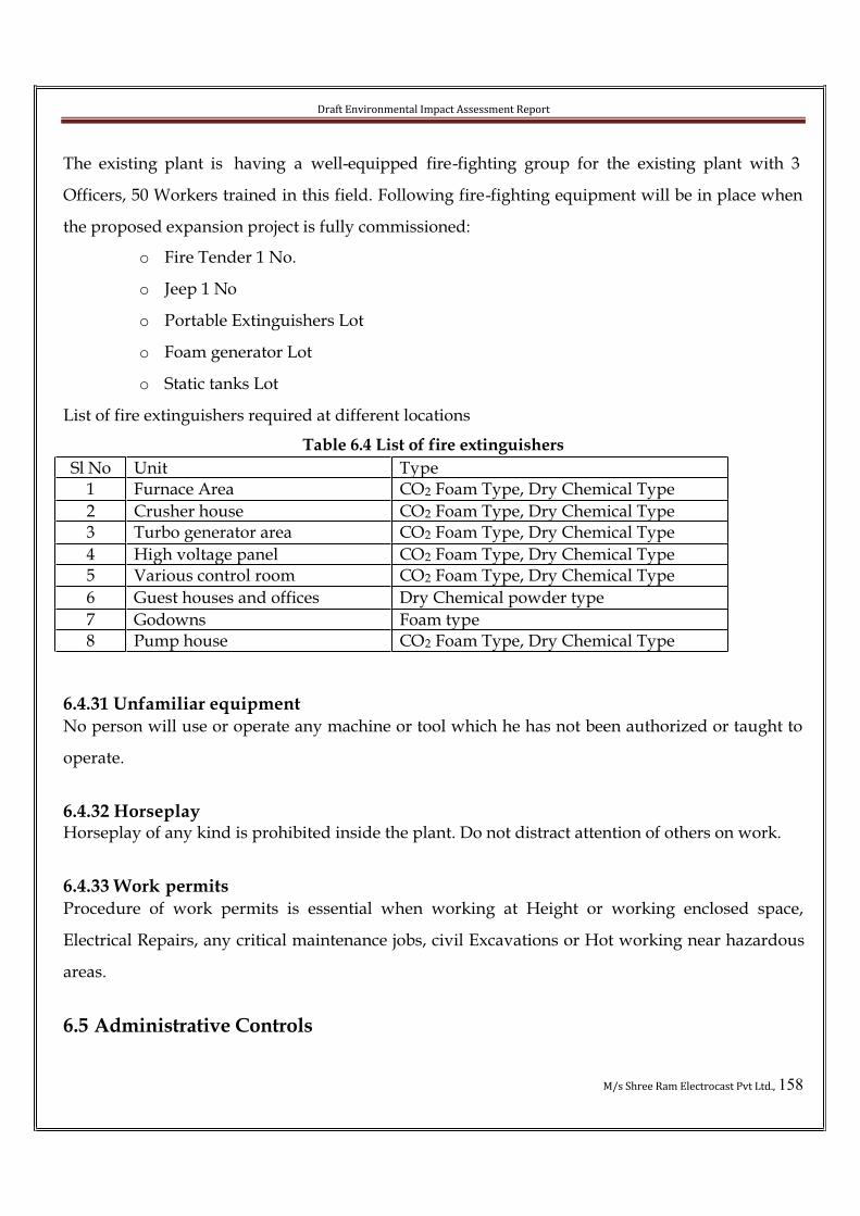
Draft Environmental Impact Assessment Report
M/s Shree Ram Electrocast Pvt Ltd., 158
The existing plant is having a well-equipped fire-fighting group for the existing plant with 3
Officers, 50 Workers trained in this field. Following fire-fighting equipment will be in place when
the proposed expansion project is fully commissioned:
o Fire Tender 1 No.
o Jeep 1 No
o Portable Extinguishers Lot
o Foam generator Lot
o Static tanks Lot
List of fire extinguishers required at different locations
Table 6.4 List of fire extinguishers
Sl No Unit Type1 Furnace Area CO2 Foam Type, Dry Chemical Type
2 Crusher house CO2 Foam Type, Dry Chemical Type3 Turbo generator area CO2 Foam Type, Dry Chemical Type
4 High voltage panel CO2 Foam Type, Dry Chemical Type5 Various control room CO2 Foam Type, Dry Chemical Type
6 Guest houses and offices Dry Chemical powder type
7 Godowns Foam type8 Pump house CO2 Foam Type, Dry Chemical Type
6.4.31 Unfamiliar equipmentNo person will use or operate any machine or tool which he has not been authorized or taught to
operate.
6.4.32 HorseplayHorseplay of any kind is prohibited inside the plant. Do not distract attention of others on work.
6.4.33 Work permitsProcedure of work permits is essential when working at Height or working enclosed space,
Electrical Repairs, any critical maintenance jobs, civil Excavations or Hot working near hazardous
areas.
6.5 Administrative Controls
Draft Environmental Impact Assessment Report
M/s Shree Ram Electrocast Pvt Ltd., 159
Administrative controls largely involve the development of safe working practices and procedures.
These controls may include:
• rescheduling hot work to cooler parts of the day and maintenance to cooler seasons;
• encouraging workers to take short breaks;
• allowing new workers or workers returning from holidays to acclimatise to the heat;
• decreasing heat exposure duration e.g. by rotation of workers;
• scheduling regular work/rest breaks in cool, shady areas with protective clothing removed;
• isolate hot work practices to times/locations distant from other workers;
• consider job sharing/rotation or using extra workers;
• screen workers for heat intolerance (e.g. those with heart and blood pressure problems or
previous heat illness);
• training of workers in the hazards associated with working in heat and recognising heat
related illnesses, safe work practices, control measures and the use and maintenance of
personal protective equipment;
• introduction of a ‘buddy system’ where workers and supervisors in hot work environments
look out for early signs of heat illness in fellow workers;
• limit consumption of diuretics e.g. caffeinated drinks and alcohol;
• workers to seek medical advice - if on medication that may interfere with heat tolerance
(e.g. blood pressure medication, sedatives, and antidepressants);
• Provision of reasonable access to an adequate supply of clean and cool drinking water. (e.g.
as a rule of thumb, workers doing hot work should drink a cup of water every 15 to 20
minutes.); and
• Develop a contingency plan for the treatment of affected workers.
6.6 Personal Protective Equipment (PPE)
Where exposure to heat cannot be prevented or reduced by any other form of control, all exposed
persons must be provided with PPE. PPE may be used in addition to other control measures.
PPE designed to protect persons in hot environments will include:
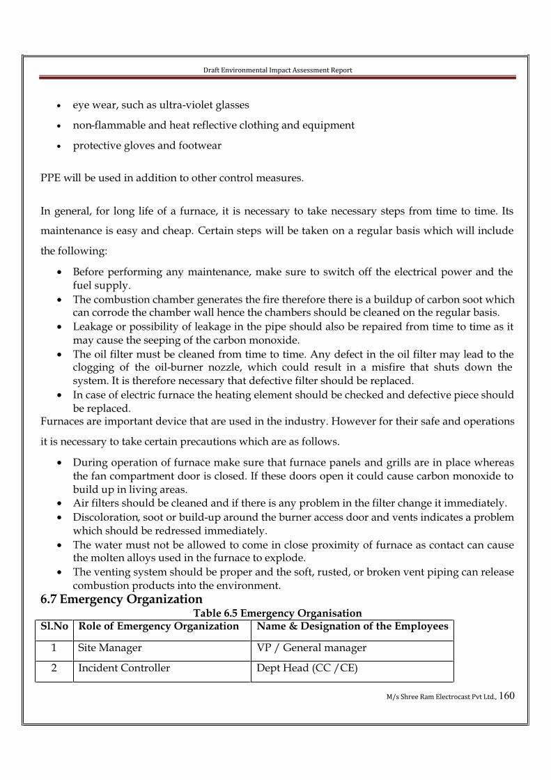
Draft Environmental Impact Assessment Report
M/s Shree Ram Electrocast Pvt Ltd., 160
• eye wear, such as ultra-violet glasses
• non-flammable and heat reflective clothing and equipment
• protective gloves and footwear
PPE will be used in addition to other control measures.
In general, for long life of a furnace, it is necessary to take necessary steps from time to time. Its
maintenance is easy and cheap. Certain steps will be taken on a regular basis which will include
the following:
• Before performing any maintenance, make sure to switch off the electrical power and the fuel supply.
• The combustion chamber generates the fire therefore there is a buildup of carbon soot which can corrode the chamber wall hence the chambers should be cleaned on the regular basis.
• Leakage or possibility of leakage in the pipe should also be repaired from time to time as it may cause the seeping of the carbon monoxide.
• The oil filter must be cleaned from time to time. Any defect in the oil filter may lead to the clogging of the oil-burner nozzle, which could result in a misfire that shuts down the system. It is therefore necessary that defective filter should be replaced.
• In case of electric furnace the heating element should be checked and defective piece should be replaced.
Furnaces are important device that are used in the industry. However for their safe and operations
it is necessary to take certain precautions which are as follows.
• During operation of furnace make sure that furnace panels and grills are in place whereas the fan compartment door is closed. If these doors open it could cause carbon monoxide to build up in living areas.
• Air filters should be cleaned and if there is any problem in the filter change it immediately.
• Discoloration, soot or build-up around the burner access door and vents indicates a problem which should be redressed immediately.
• The water must not be allowed to come in close proximity of furnace as contact can cause the molten alloys used in the furnace to explode.
• The venting system should be proper and the soft, rusted, or broken vent piping can release combustion products into the environment.
6.7 Emergency OrganizationTable 6.5 Emergency Organisation
Sl.No Role of Emergency Organization Name & Designation of the Employees
1 Site Manager VP / General manager
2 Incident Controller Dept Head (CC /CE)
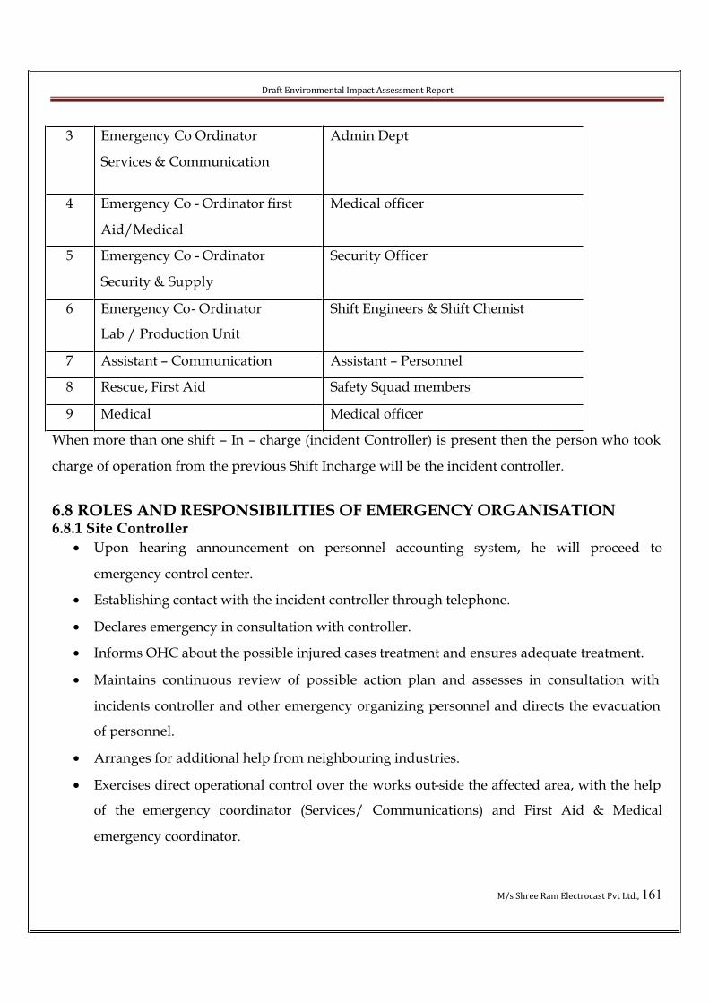
Draft Environmental Impact Assessment Report
M/s Shree Ram Electrocast Pvt Ltd., 161
3 Emergency Co Ordinator
Services & Communication
Admin Dept
4 Emergency Co - Ordinator first
Aid/Medical
Medical officer
5 Emergency Co - Ordinator
Security & Supply
Security Officer
6 Emergency Co- Ordinator
Lab / Production Unit
Shift Engineers & Shift Chemist
7 Assistant – Communication Assistant – Personnel
8 Rescue, First Aid Safety Squad members
9 Medical Medical officer
When more than one shift – In – charge (incident Controller) is present then the person who took
charge of operation from the previous Shift Incharge will be the incident controller.
6.8 ROLES AND RESPONSIBILITIES OF EMERGENCY ORGANISATION6.8.1 Site Controller
• Upon hearing announcement on personnel accounting system, he will proceed to
emergency control center.
• Establishing contact with the incident controller through telephone.
• Declares emergency in consultation with controller.
• Informs OHC about the possible injured cases treatment and ensures adequate treatment.
• Maintains continuous review of possible action plan and assesses in consultation with
incidents controller and other emergency organizing personnel and directs the evacuation
of personnel.
• Arranges for additional help from neighbouring industries.
• Exercises direct operational control over the works out-side the affected area, with the help
of the emergency coordinator (Services/ Communications) and First Aid & Medical
emergency coordinator.

Draft Environmental Impact Assessment Report
M/s Shree Ram Electrocast Pvt Ltd., 162
• Liaison with government officials Viz, District Commissioner, Pollution Control Board, Fire
Services, Department of Explosives and Inspector of Factories and Boilers if required.
• Once the situation is brought under control, call-off onsite emergency in consultation with
incident controller and instructs security for blowing all clear signal.
6.8.2 Incident Controller• As soon as incident controller receives the message of incident he will rush to spot.
• Use public address system to call safety squad of other departments.
• Organizes to switch on flashlights relevant to the building affected.
• Send all visitors and contact people to assembly point.
• Start controlling emergency with available safety squad.
• Depute safety squad for rescue of injured persons.
• Assess the situation and advise site controller to call for emergency by phone.
• Organize for safe shut down of the plant if deemed necessary and evacuate employees of
the department (in the event of public address system failure).
• Assigns jobs to safety squad viz. a) rescue, b) leakage control, c) fire fighting d) evacuation
as per the need of situation.
• Inform to the site controller by phone regarding the steps taken to mitigate the emergency
from time to time.
• Organize to barricade the area by using warning tape.
• Depute safety squad from search of missing people as per information received from the
site controller.
• Upon completion of controlling operations, ensures area is free of toxic material and inform
to the site controller to declare “ALL CLEAR”.
6.8.3 Emergency Coordinator (Services & communication)• Upon hearing the siren he will rush to the emergency control center and reports to the
controller with the attendance record for the employees list workmen and visitors.
• Act as per the instruction of site controller and maintain log of incident.

Draft Environmental Impact Assessment Report
M/s Shree Ram Electrocast Pvt Ltd., 163
• Arrange for transport of injured and ensure transport for additional injured persons.
• Arrange for external medical treatment for injured and casualties.
• Report to the hospital and make arrangement for likely more cases of injuries.
• Appoint responsible personnel from factory to assist injured who is under medical
treatment.
• Communicate information to ESI and Labor Commissioner.
• Communicate information to the relatives of the injured/ deceased.
• Calling neighboring factories for help like transport, fire fighting services, paramedical and
antidotes.
• If required communicate to the Fire Services, pollution Control Board, Inspectorate of
Factories, or other departments in consultation with site controller.
• Appoint three people to act as a runner incase of communication failure.
6.8.4 Emergency Coordinator (First Aid & Medical Management)
• Upon hearing the siren rush to OHC (Occupational Health center).
• Take charges of safety squad reported to OHC and retain one /two safety squad at OHC.
• Arrange for first aid and specific treatment with the advice of doctor.
• Organize to the shift injured to clinic with relatives MSDS, first aid manual (for specific
chemical exposures ref. first Aid manual) and antidotes. Accompanies the victim if the case
is critical based on doctor’s advice.
• Incase of need arrange for shifting to other medical centers as the case may be, maintain
contact with site controller from time to time
6.8.5 Emergency Coordinate (Security & Supply)
• Upon hearing the siren, all material transport vehicles will be sent out and close the gate.
• Restricts visitor entry inside the premises.
• Direct the ambulance to the vicinity of the incident.
• Ensures all security guards are reporting to main gate. Send one person to main road to
bring fire tender if it is called.

Draft Environmental Impact Assessment Report
M/s Shree Ram Electrocast Pvt Ltd., 164
• He will rush to the scene with shift security inspector and reports to the incident controller
except in cases of toxic release.
• Additional fire extinguishers, hoses, nozzles, form compound located in various points shall
be drawn and arrange for fire fighting
• Organize to open the main gets as soon as the ambulance reaches OHC
• Co-ordinates with fire bridge group and help them.
6.8.6 Emergency Coordinator (Production Unit)
• Upon hearing the siren / message rushes to the site of the incident and reports to the
Incident Controller and Emergency Coordinator (Services & communication).
• If anyone is injured on the job, immediately send them to OHC .
• Arrange for Shut-down the plant/ unit as per the instruction of Emergency coordinator
(Utility and Maintenance) and Incident Controller.
• Arrange the workers at the production unit to assemble at the assembly point.
6.8.7 Emergency Coordinator (Utility & Maintenance)
• Upon hearing the siren / message rushes to the site of the incident and reports to the
incident controller
• Appoints one technician as in charge of fire extinguisher
• In consultation with incident controller, arrange power supply cut –off to the affected area.
Ensures that, emergency power and water supply is on.
• Arrange for shut down of non – essential utilities as per instruction of incident controller
• Consults incident controller and with the help of Eng Dept. and safety executes the leakage
control operations.
• Arranges for changeover of pumps and systems with standby incase of difficultly
6.8.8 Assistant – Communication
• Upon hearing emergency siren, she / he will immediately contact site controller. Incase if
telephone system becomes inoperative she / he receives the information regarding fire or
toxic release from a person who detected it, thereafter immediately informs to the incident
controller and site controller.
Draft Environmental Impact Assessment Report
M/s Shree Ram Electrocast Pvt Ltd., 165
• Directs all visitors in the reception to assembly point.
• She / He will continue to operation the EPABX board and pass all class connected with
incident to the site controller emergency controller center.
6.8.9 Safety squad
• Upon hearing the emergency instruction from public address system, informs to the
available superior and rush to the location of emergency.
• Carry at least one fire extinguisher or stretcher, artificial resuscitator and reports to the
incident controller and works as per his direction.
• Do fire fighting / rescue / first aid / evacuation and leakage control as directed by the
incident.
6.8.10 Drive – Ambulance
• Upon receiving instruction from emergency coordinator (Security and supply) he, should
proceed to the vicinity of spot and reveres the vehicle.
• Parks the vehicle nearer to the incident place in case of toxic releases as directed by the
Emergency coordinator (Security & supply)
• Keeps engine in running condition
• Opens the back door of the ambulance
• Goes back to the seat
• Takes the injured to the OHC, the vehicle and opened the back door and reports to in charge
OHC.
6.8.11 In Charge – Occupational Health Center• Stays on alert for first aid and medical treatment for chemical poisoning and other injuries.
• Goes to the ambulance at OHC gate to receive the injured, examines and quickly assess the
condition and treats. Shifts the injured to Health Center if required advance the emergency
coordinator to accompany the victim incase of the condition is critical. He stays in OHC for
treatment of subsequent injury cases if any or till all clear siren is blown.

Draft Environmental Impact Assessment Report
M/s Shree Ram Electrocast Pvt Ltd., 166
• Gathers feed back from primary Health center and communicates to the site controller /
Emergency / coordinator medical
6.8.12 Department heads / shift / in charge / supervisors
• Upon hearing the emergency announcements through PAS, send the safety squad members
of their departments to the site of incident.
• Sends contract workers and visitors to reception / assembly point indicating correct
evacuation path
6.8.13 Duties of Receptionist / Telephone Operator
• At the time of emergency, direct one line to the Site Controller’s office.
• On receipt of instructions from the Site Controller, notify the fire Brigade / Police /
Hospitals for any assistance as required.
• Keep the switchboard open for emergency calls.
• Refrain from exchanging any information pertaining to the emergency and reference about
the incident from the authorized personnel to the Site Controller.
• Keep logging of the calls received for the possible call back.
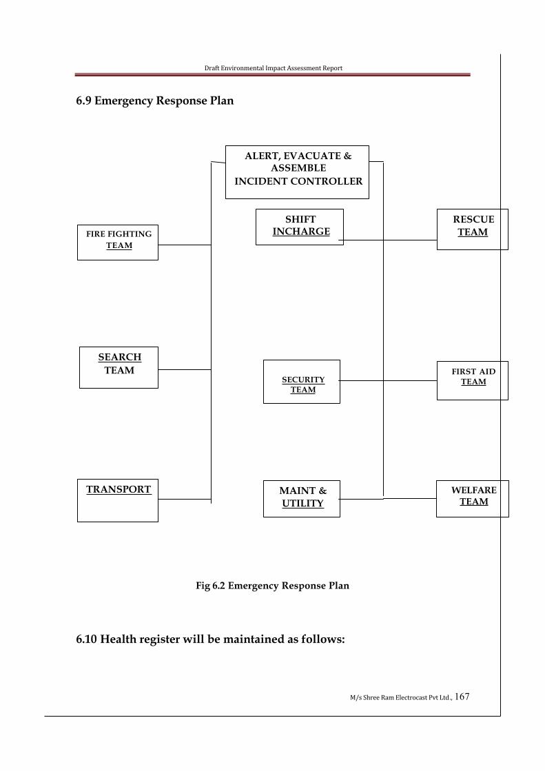
Draft Environmental Impact Assessment Report
M/s Shree Ram Electrocast Pvt Ltd., 167
6.9 Emergency Response Plan
Fig 6.2 Emergency Response Plan
6.10 Health register will be maintained as follows:
ALERT, EVACUATE & ASSEMBLE
INCIDENT CONTROLLER
FIRE FIGHTING
TEAM
SHIFTINCHARGE
RESCUE
TEAM
SEARCH
TEAMSECURITY
TEAM
FIRST AID TEAM
TRANSPORT MAINT &
UTILITY
WELFARETEAM
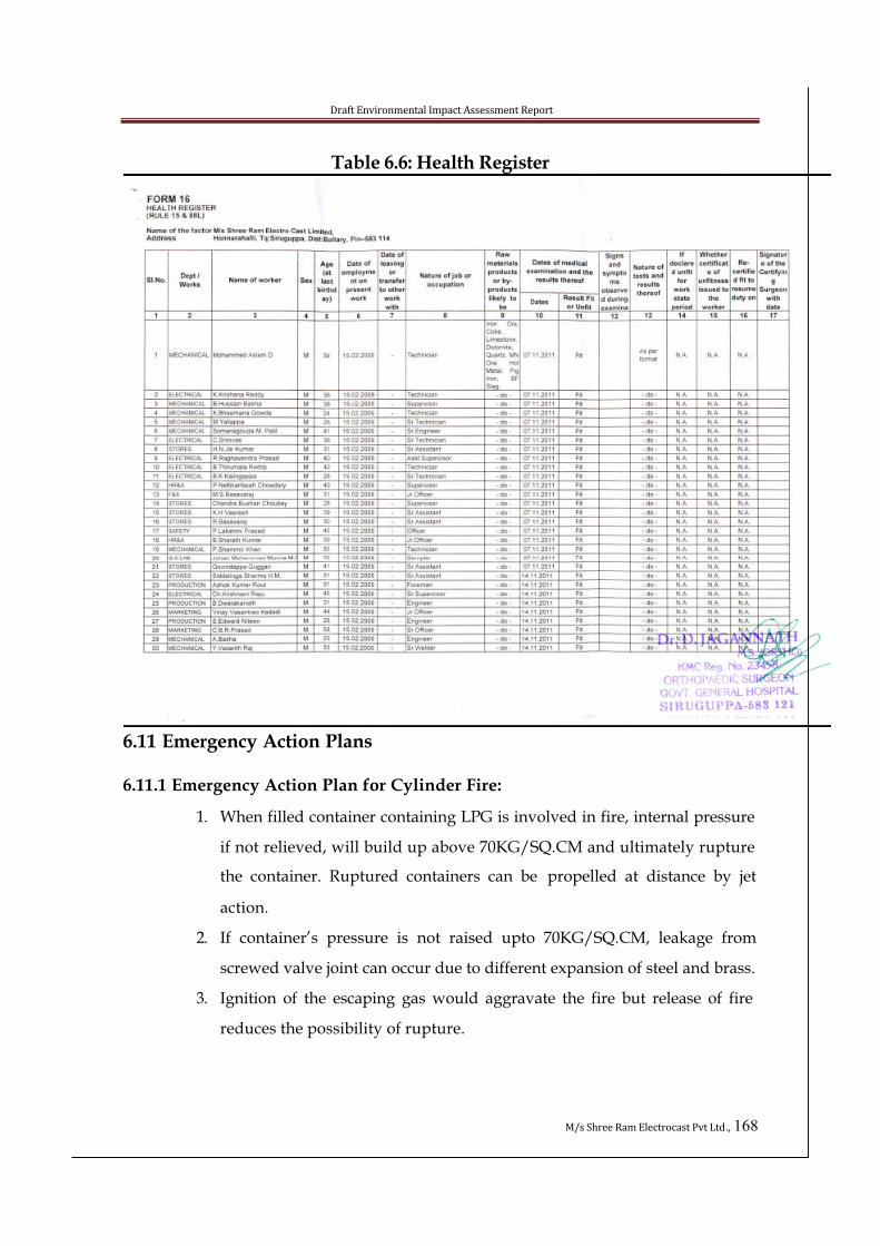
Draft Environmental Impact Assessment Report
M/s Shree Ram Electrocast Pvt Ltd., 168
Table 6.6: Health Register
6.11 Emergency Action Plans
6.11.1 Emergency Action Plan for Cylinder Fire:
1. When filled container containing LPG is involved in fire, internal pressure
if not relieved, will build up above 70KG/SQ.CM and ultimately rupture
the container. Ruptured containers can be propelled at distance by jet
action.
2. If container’s pressure is not raised upto 70KG/SQ.CM, leakage from
screwed valve joint can occur due to different expansion of steel and brass.
3. Ignition of the escaping gas would aggravate the fire but release of fire
reduces the possibility of rupture.
Draft Environmental Impact Assessment Report
M/s Shree Ram Electrocast Pvt Ltd., 169
4. No attempt should be made to extinguish the burning gas but the
container under fire and other containers in vicinity should be kept cool by
water spray.
5. If the gas leakage does not ignite, the container should be approached
from up and removed to the place of safety away from the source of
ignition.
6.11.2 Emergency Action Plan for Electric Fire:
1. Disconnect the affected areas electric supply.
2. Attempt to extinguish fire with the help of CO2, DCP
3. If fire is not extinguished, extinguish by spraying water with fog nozzle
after ensuring complete isolation of electric circuit.
6.11.3 Emergency Action Plan for Office Fire:
1. Disconnect electric supply of the affected area.
2. Attempt to extinguish the fire with the help of CO2, DCP and sand.
3. If large fire, use hydrant system.
4. Attempt to save the record.
5. Attempt fire extinguisher.
6.11.4 Emergency Action Plan for Oil Fire:
1. Attempt to extinguish small fire with the help of DCP
2. If the fire is not controlled, use water foam to blanket the fire and
further action is to be taken
The proposed project will provide elaborate arrangements for managing any
incidents of fire:
• Portable Pump
• Wireless set
• Water Hoses
• Hot line Telephone etc.,
Draft Environmental Impact Assessment Report
M/s Shree Ram Electrocast Pvt Ltd., 170
6.11.5 Emergency Action Plan for Medical Aid:
i. Emergency Action Plan for Electric Shock Casualties:
Electric shock results in:
Irreversible damage to brain cell begins followed by deterioration of the organs.
Rescue and first aid:
Do first aid quickly and without fuss and panic
� Switch off the supply if this can be done at once.
� If not possible use a dry stick, dry cloth or other non-conductor to separate the
victim from electrical contact.
� The rescuer must avoid receiving shock himself by wearing gloves or using a jacket
to pull the victim.
� Always keep in mind that delay in rescue and resuscitation may be fatal. Every
sound counts.
ii. Artificial Respiration:
Give artificial respiration if breathing has stopped. There are several methods of
artificial respiration, if the victim is nit injured over the face, try mouth to mouth.
a) Mouth to Mouth Method:
1. If there is obstruction to breathing, remove it with your fingers if it in
mouth. Several sharp blows between shoulder blade may help to is
lodge an obstruction.
2. Lay casually on his back, put something under his shoulder to raise
them & allow his head to fall backwards. The head should be, if possible
be a little lower than the trunk. Remember that speed is essential.
3. Kneel at the causalities head and grasp his arms at the wrists then cross
them firmly over the lower chest. This movement should force air out of
his lungs. Press with the hands crossed on the lower part of the chest
and maintain pressure for two seconds.
4. Release this pressure and pull out his arms with a sweeping movement
Draft Environmental Impact Assessment Report
M/s Shree Ram Electrocast Pvt Ltd., 171
upwards and outwards above his head and backwards as far as possible.
5. This movement should cause air to be drawn in to his lungs. Retain the
arm in this position for three seconds.
6. Repeat these movements rhythmically about twelve times a minute
checking the mouth frequently for obstructions. Each cycle will thus take
give seconds- two seconds for chest pressure and three seconds for arm
lift.
7. With the causality on his back there is danger of aspiration of vomit,
mucus or blood reentering the system. This risk can be reduced by
keeping his head extended and a little lower than the trunk.
8. If an assistant is available, he can press the causality lower jaws so that
the chin is jutting out.
9. The assistant should also ensure that the mouth is kept open as far as
possible and head is tilted to one side.
10. When natural breathing begins, your movement should be adapted to
correspond to it.
11. If burns are present, cover them with a dry sterile dressing
12. Handle the causality gentle
13. Do not allow people to crowd around and block fresh airflow.
14. Arrange to remove the injured to the care of a doctor as early as possible.
6.12 Natural Hazards
6.12.1 Emergency Action Plan for Tornado/High Winds:
a. Weather reports will be monitored from broadcast warnings regarding
threatening conditions.
b. If the tornado has been sighted or effect is felt, following steps should be
taken by plant personnel.
� Persons will be notified over public address system or through siren.
� Emergency services will be alerted for assistance.

Draft Environmental Impact Assessment Report
M/s Shree Ram Electrocast Pvt Ltd., 172
� Plant personnel should be advised to assemble in the administration building
basement, staff room, recreation room and rest rooms.
� All safety systems should be kept on alert and all nonessential utilities should be
put off.
c. After the status is restored, personnel should inspect all the facilities for resource,
first aid and damage control activities, damage assessment, and clean up,
restoration and recovery.
6.12.2 Emergency Action Plan for Earthquakes
1. When first tremors are sensed during an earthquake, all personnel
should evacuate buildings and assemble at safe place away from
structures, walls and falling objects. Emergency shut down should be
declared.
2. Emergency services should be contacted for assistance.
3. After the status is restored, personnel should inspect all the facilities for
rescue, first aid and damage control activities, damage assessment,
cleanup, restoration and recovery.
6.12.3 Emergency Action Plan for Bomb Threat
When bomb threat call is received the following measures are to be taken.
• Inform the message to the highest local police authority and seek their
assistance for patrolling and security need.
• Inform Controller of Explosives the details and nature of the anonymous
message and read operations.
• Request the Local Fore Brigade to position at least on fire te nder at the
Location immediately.
• Keep the Concerned Department at the Regional Level informed with
the developments at regular intervals.
• Alert the Local Government / Private Hospitals and seek their help for
providing Ambulances if necessary

Draft Environmental Impact Assessment Report
M/s Shree Ram Electrocast Pvt Ltd., 173
6.12.4 In T he Location Premises:
• Keep the Fire Hydrant System/all Fire Fighting and Personnel
protective Equipment in readiness.
• Every one entering the Location must be frisked at the Gate/check all
Hand Bags, Parcels etc., for suspected explosive/dangerous objects.
• Have thorough inspection of the Location for any suspected dangerous
object.
• Materials and other Boxes to be brought in to the Location must be
deposited at Gate for minimum curing period of 48 Hrs.
• Organize Employees Vigilance cell for round the clock observation of
industry Premises.
6.12.5 If The Suspected object is found:
• In case of finding of suspected Article, do not disturb its position, but the
area around it should be cordoned off to a distance of 100 meters and
more depending upon the gravity of situation.
• Adequate Staff or Police Squad posted to prevent any unauthorized
entry into the enforced cordon.
• Contact Controller of Explosives immediately, who on reaching the Site
will decide suitable action for defusing and disposal of the suspected
object.
• Evolution of thick billowing smoke is an indication of impending
explosion and in such a case, with draw or evacuates all personnel from
the spot, which has been identified.
• As a general measure regulate the movement of the outsiders inside our
Premises and restrict their entry with permits.
6.13 GUIDELINES FOR SHUTDOWN OF PRODUCTION BLOCKS
The only major potential hazard that may occur in the factory is fire immediate action to
be taken in each of the section for the purpose of emergency shut down would be as
under

Draft Environmental Impact Assessment Report
M/s Shree Ram Electrocast Pvt Ltd., 174
Manufacturing Unita) Cut – off electrical mains
b) Shut down the plant.
As decided by the incidents controllers efforts will be needed to shut down and make
the production block safe with the guidance of shift in charge.
• Remove chemicals stored ne ar vicinity of fire.
• Ensure that the power supply for firewater pump, emergency lighting, UPS
systems, cooling water, brine circulation are ON
• Isolate power supply to centrifuges, reactor agitators and pumps
• Ensure circulation of cooling water to all reactors jackets for 60 minutes.
• Stop thermo fluid heater firing and keep the pump in cooling mode.
• Stop material transfer operations in the production block. Cut-off solvent supply
to crab block from tank area.
6.14 EMERGENCY PLANNING
6.14.1 TRAINING AND RE HEARSAL
The electrical system as well as the areas where high temperature prevails in the
working areas precautionary measures may guards, caution boards, foolproof measures
will have to provide accidents.
• It is most essential for all the teams to act in accordance with patience in the
emergency condition. To act accordingly the workers are trained in the first aid
treatment and fire fighting. The training and the rehearsals for fire fighting an
emergency evacuation is carried out to avoid, confusion that might arise during
the actual emergency.
• For fire fighting given by the security officer to the staff and also the government
Fire force training institute personnel will be asked to give further training and
the Red Cross Association personnel will train personnel in first aid procedures.
• It is also the responsibility of the emergency declarer / controller to train the
teams in their respective area of operation during emergency and to carry out
mock drills at least in 6 months.
Draft Environmental Impact Assessment Report
M/s Shree Ram Electrocast Pvt Ltd., 175
6.14.2 ACTION PLAN / TRANING
• To evacuate the persons unnecessary in that section
• Sooner grasp the situation/ hazards, issue instructions to the helping hands to
curb/ control the situation.
• Incase of fire, fire brigade will be called.
• Along with the fire brigade, the trained workers in the fire fighting procedure
and organize controlling / extinguishing the fire.
With a view to ensure that declarer/ controller of Emergency shall have assistance that
is required at his/ their disposal at the time of occurrence of the emergency teams of
personnel are formed to take up positions when the situation arises.
6.14.3 GENERAL SAFETY
• Ensure that surrounding facilities do not emit any chemical waste or gases,
which affects the health of personnel at the facility. Continuous monitoring
should be ensured.
• The designing of the drains within the plant and surroundings of the facility
should be of closed type, which would prevent the back flow.
• Any drains outside the facility should be closed and if open spray them with
disinfectants and pesticides. Also ensure water does not stagnate in the drains.
• The area surrounding the processing areas should have a uniform floor level,
without any humps or ditches, which leads to stagnation of waste water during
the rainy season and in turn helps in the breeding of insects or flies which play a
major role in spreading of many diseases.
• Floor openings in the form of pits/ sumps should be properly manned, so that
manoeuvring becomes easy and safe. The pit / sump should be highlighted with
a red flag/ cloth with a sign “Danger” marked on the cloth and hoisted near the
pit/ sump.
• Ensure there is no growth of grass beneath the electrical transformer.
• Design, installation of generators as an independent block away from the
processing area.
• Ensure adequate fire safety measures near the diesel tanks.
• Avoid misuse of sand buckets meant for fire extinguishing.

Draft Environmental Impact Assessment Report
M/s Shree Ram Electrocast Pvt Ltd., 176
• Store the organic solvents in a separate storage area away from the main
warehouse.
• Whenever an order is placed for procurement of organic solvents in bulk, ensure
that they are transported by an open vehicle.
• Conduct pest control activities, during the closing hours of the factories and
ensure there are no men or material movement from or to the facility.
• In no circumstances should the, hazardous and toxic materials handled within
the licensed premises.
• Do not enter the processing area, until unless a need arises and also ensure
authorization to enter the area.
• In the processing area, insist safety aspects by displaying appropriate
signboards. For Example: “Mind steps”, “Entry Restricted”, “Danger”,
“Emergency Exit”, etc.
• Provide emergency exists whenever designing any facility. The Emergency exit
should be easy in manoeuvring. They should never be locked at any time.
• Smoking should strictly be restricted in and around the processing area, as a
precautionary measure against fire accidents.
• Ensure ladders are being used wherever necessary instead of using shortcuts,
like climbing through pipes etc.
• Avoid spillage of any material during processing. In case it happens, this should
be immediately brought to the notice of the production officer and ensure
immediate cleaning as per the standard operating procedures.
6.14.5 SAFETY WHILE HANDLING EQUIPMENT
• Only trained and authorized personnel should operate the Equipment.
• Operate all equipments, only through approved operating procedures.
• Do not operate any machine without safety guards in place.
• Do not bypass the safety locks whenever there is an automatic locking system.
• Do not touch or alter any part of the machine, while machine is in operation.
• Ensure that all moving parts of the equipments are fixed properly to the machine,
prior to operation.
Draft Environmental Impact Assessment Report
M/s Shree Ram Electrocast Pvt Ltd., 177
• Do not wear loose garments when operating machinery.
• Do not indulge in maintenance activities during the operation.
• Ensure there is no spillage of oil or grease around the machinery, during
maintenance.
• If oil or grease is spilt, clean the area immediately with a cloth and store it in a
separate container till they are incinerated.
• Ensure that the Dust extraction system is working, when the machine is in
operation.
• If any abnormal sound is heard, report it immediately to the production
supervisor.
• Ensure that the surrounding area of the machinery is neat and clean.
• Do not run the machine when it is empty.
• Do not stand below any lifting, positioning or tippling devices.
• Ensure arrest of electricity supply on equipments prior to cleaning.
• Wherever pressure gauges are provided, ensure their functioning prior to
initiating operation.
• Whenever the equipment is provided with steam supply ensure proper draining
of the condensate.
• Do not try to operate any equipment, which is labeled “Under Maintenance”.
• Carryout planned preventive maintenance as per the schedule, to avoid any
discrepancy in equipment operating parameters.
6.14.5 ELECTRICAL SAFETY1.Electrical maintenance should be carried out only by trained and authorized
personnel of engineering department.
2.If any equipment gives an electric shock, disconnect the equipment from the
electricity supply and immediately inform the engineering department and the
hand over the equipment to them.
3.Whenever working on live circuits or during maintenance of electrical equipment
wear rubber gloves and rubber foot wear.
4.Ensure adequate earthing for all equipments.

Draft Environmental Impact Assessment Report
M/s Shree Ram Electrocast Pvt Ltd., 178
5.Whenever any electrical fuse is replaced, ensure that the fuse replaced is of same
capacity.
6.Ensure closing of power cabinet, after maintenance works.
7.Avoid usage of unsuitable switches or plug-pins.
8.Whenever any equipment, which is power driven, is taken for maintenance, ensure
there is no power supply. Remove all the fuses of the equipment ad store it in a
secure place. After completion of maintenance job, ensure replacement of fuses.
9.Do not use water or wet mop to clean the electrical panels. Use only dry, non-
shredding cloth for cleaning.
6.14.6 FIRE SAFETY
NOTICING EMERGENCY
6.14.6.1 FIRE
Any person noticing the fire will start shouting “ fire”, “fire” till assistance is arrives.
Simultaneously he shall attempt to extinguish the fire by using a suitable fire
extinguisher. Any person who hears shall intimate the shift in-charge / safety officer
personally shift in charge / safety officer will reach the incident spot by protecting
himself and upon assessing the situation he shall seek help of safety squad by using
public address system. He will also inform to the site controller and chief executive by
telephone or through a messenger immediately.
The safety squad soon after reaching the fire spot shall start fire fighting to the extent
possible by standing in upwind direction and keeping the passages and doors clear. If
necessary shift in-charge / Safety officer will instruct the senior chemist for plant shut
down of the affected area immediately. All visitors and contract employees will be
directed to assembly point by respective departmental head or his alternate, upon
hearing message on personnel accounting.
Upon assessing the situation the incident controller will advice the site controller to
declare emergency through siren hooting followed by evacuation of all employees.
All production, quality control and utility areas of the facility are provided with fire
safety instruments.
Draft Environmental Impact Assessment Report
M/s Shree Ram Electrocast Pvt Ltd., 179
Whenever there is a fire, the following actions are to be taken of:
� All the equipments shall be switched off along with the mains.
� Rescue men and machines followed by the documents.
� The fire -hit area should be blazed off with water, and the head of the department
should be summoned immediately.
Fire Extinguishers are to be used by the trained in-house personnel. At least two people
from each department shall be given training in operating fire extinguishers.
6.14.6.2 FIRE FIGHTING, RESCUE AND FIRST AID TEAMAction taken by Trained Volunteers
The trained volunteers who are available at the site at the time of emergency will report
to the incident controller. They will wear their identification badges for identification.
First Aid Team
• Chief : Admin Executive
• Alternate : Shift Operator
Functions
First aid is given to persons before sending them to hospital. First aid team has to bring
all the first aid items at the control room to administer first aid.
1. Injured / affected workmen shall be given immediate first aid with the help of
trained personnel amongst the workmen.
2. Following antidotes should be kept ready for use. Suffocation: remove the person
to the fresh air and administer the oxygen.
Rescue Team
• Chief : Process Engineer
• Deputy : Shift Operator
• Alternate : Shift Operator
Functions
1. Rescue the victim in the affected area
2. Bring the people out of the area and hand over to first aid team.
3. Use stretcher, breathing apparatus, fire suits etc., if and when required.

Draft Environmental Impact Assessment Report
M/s Shree Ram Electrocast Pvt Ltd., 180
Fire Fighting Team
• Chief : Security Head
• Deputy : Shift Operator
• Alternate : Shift Operator
Functions
1. Fire should be controlled in the incipient stage. Use portable fire
extinguisher depending upon the classification of the fire like A, B, C, D or
E.
2. When it starts spreading, use fire hydrant system.
3. Use hydrant as water curtain to avoid spreading.
4. Keep checking the water level in the reservoir. If less than 40 % then call
outside help.
6.15 DECLARATION OF EMERGENCYUnder this plan the following post occupier are nominated as the Declarer / controller
of Emergency
Managing Director/Chief Executive Officer/ General Manager
As soon as they get information from the shift in-charge, they / he will arrive at the
place of hazard and assess the situation and decide to declare the emergency pertaining
to the particular section or entire plant and sound the siren accordingly.
a) If emergency is declared is to be declared only in one plant / Section the other
plant/ section will work normally.
b) They / he shall take over the situation and shall start functioning in such a
manner have to control the situation and curb the situation as soon possible.
6.1 6 EMERGENCY SIRENShift security Inspector will sound the emergency siren following instruction received
from the incident / site controller. Intermittent hooting will be made continuously 3
minutes to declare emergency the purpose is to advise a personal that emergency has
occurred in the plant.

Draft Environmental Impact Assessment Report
M/s Shree Ram Electrocast Pvt Ltd., 181
6.1 7 EVACUATION OF PERSONNELWhen a major accidents occur and there is only cause or trouble in which case any
employee or any human life faces the problem of self evacuation even though having
the knowledge of evacuation plan, then it is the entire responsibility of the team for to
evacuate all the persons and provide all the medical facility of the team for to evacuate
all the persons and provide all the medical facilities. In first place the trained persons in
the ambulance room shall give first aid treatment, and they may be transported to the
factory hospital or medical center nearby in the ambulance. There are clearly marked
gangways inside the plant and around the factory premises with fire exists provided on
ground floor which are also clearly marked with evacuation plan along with fire
extinguishers and fire alarm. The employees are trained to choose the safest and nearest
gangways to come out of danger area and arrive at safe place as early as possible.
6.1 8 SAFE ASSEMBLY POINTSSafe Assembly Point is located in front of the main gate
6.19 ACCOUNTING OF PERSONNELWhen person engaged the emergency, the section in-charge are responsible to bring out
the employees to safe place and make the arrangements for their medical treatments,
Department head also visit site of emergency to ensure that nobody has been trapped.
The person who has engaged/trained in the First – Aid and fire fighting also check up
for ensuring that nobody has been trapped.
It shall be the responsibility of the Emergency Coordinator (Security and Supply), to
verify the persons on duty and check whether all the persons have come out of
hazardous zone also shall coordinate with Emergency Coordinator (Production) and
checks and recheck so that all personnel are around and also Incident Controller will
counter check with the security of any visitors, transport workers and contract labors
have entered the plant and is so, they should also be accounted for.
6.2 0 ARRANGEMENT FOR MEDICAL TREATMENTGeneral First aid will be given within the factory and Injured will be transferred to
Government Hospital which is at a distance of 2 KM from the site.

Draft Environmental Impact Assessment Report
M/s Shree Ram Electrocast Pvt Ltd., 182
Sl.No. Hospital name. Location. Phone Nos.
01 Govt. Hospital Siruguppa. 220249
02 Laxmi Nurseing Home. Siruguppa. 220470
03 Sneha Helth Care Unit. Siruguppa. 22077104 Sulochana Clinic Siruguppa. 220517
05 Vijay Marie Hospital Siruguppa 220203
06 V.I.M.S Bellary siruguppa 242312,242099
6.2 1 INFORMATION TO RELATIVES OF INJUREDThe relatives of injured will be informed by emergency coordinator (Services &
Communication) only. The employee’s residential address file will be available at
emergency control center and also in the residence of emergency coordinator (Services
Communication). The communication to the relatives of injured will be passed on
through telecom or by messenger with a car. The clear details of the injured person
(local residential address, address if hospitalized) will be communicated to his relatives.
6.2 2 INFORMATION TO LOCAL AUTHORITIESIncase of emergency the Director of factories and Assistant Director of Factories will be
informed. The information will be passed on over telecom, telegram or through a
messenger deputed by emergency coordinator (Services & Communication)
The company will implement the advice of local authorities in improving the safety in
dealing with the event.
Karnataka State Pollution Control Board authorities will be informed in case of
accidents like toxic release, leakage of hazardous chemicals.
Govt. Authorities. Address. Telephone Nos.
Tahasildar Siruguppa. 230238.Dy. Commissioner cum D.C.compound, Bellary. 277100,250089.
District magistrate
Sr.Asst.Director of Factories Bellary 277474
Superintendent of Police Bellary 276000Fire officer Siruguppa 220100
Chief fire officer Bellary 231933
Pollution control Board Bellary 258365Electrical Inspictor (KPTCL) Bellary 267648
6.2 3 INFORMATION TO DISTRICT AUTHORITIES
Draft Environmental Impact Assessment Report
M/s Shree Ram Electrocast Pvt Ltd., 183
The Emergency Coordinator (Services & Communication) is authorized to inform to the
police. The Inspector of Police will be informed for the control of law & order situation
at the plant or vicinity or at hospital where injured are under treatment. The
communication will be made to the Deputy Superintendent of Police and also police
department will be required for protecting the lives of the workers, control of the traffic
arrangements, for evacuation of personnel outside the plant. Deputy Commissioner and
Superintendent of Police also will be informed regarding emergency.
6.2 4 LAW & ORDERThe information regarding emergency is set to government authorities/ general public
by the Declarer/ Controller of emergency to ensure law and order situation is fully
under the control.
Sl.No. Designation. Address. Telephone Nos.
01 Sub Inspector of Police Rural police station 241613Hatcholli.
02 Circle Inspector of Police Police Station Siruguppa. 220333
6.2 5 ALL CLEAR SIGNALAfter the situation is brought under control the emergency will be called-off by incident
controller.
2 Minutes continuous blast will denote all clear and restoration normalcy. Once the
emergency is called-off, detailed inspection is conducted by emergency organizing
personnel. On their satisfaction of the situation the incident controller will give
clearance to resume the plant operations over PA system.
An OSH management system will contain the following main elements:
(a) OSH policy;
(b) Necessary conditions for the executing organization, i.e. establishment of
responsibility and accountability, competence
and training, documentation, communication and in-formation;
(c) hazard and risk assessment, planning and implementation of OSH activities;
(d) evaluation of OSH performance and action for improvement.
Draft Environmental Impact Assessment Report
M/s Shree Ram Electrocast Pvt Ltd., 184
6.2 6 Occupational Health Surveillance ProgrammeOccupational health problems of personnel working in the main plant will be of concern
for the management.
Pre-placement Assessment
Procedures for pre -placement health examination are as follows:
• Baseline health data such as height, weight and vital statistics
• A detailed history of previous diseases and occupational exposures.
• A history of personal hobbies or activities that might involve exposure to
potential toxicants
• Past or present history of any allergies including astama
• Identification of personal habits (smoking, hygiene, alcohol consumption,
fingernail biting, etc.,) that may be relevant to work
• Complete physical examination with special attention to respiratory, dermal and
possible renal problems.
In addition to the items listed above, number of clinical tests will be performed to better
characterize the baseline data. These include:
• Posterior/anterior chest x-ray
• Lung function tests using classical spirometry
• Audiometric testing and
• Visual testing
The employees working in the main plant area will be subjected to regular health check
up. Auditory examination by qualified doctor upon the first employment and thereafter
periodic examination at least once a year will be conducted which will include the
following:
• determination of auditory threshold
• respiratory functions
• lung function test
• sputum test
Draft Environmental Impact Assessment Report
M/s Shree Ram Electrocast Pvt Ltd., 185
• visual testing
• X-ray test
• Complete physical examination with special attention to respiratory, dermal and
possible renal problems.
All workers exposed to high level of noise as well as other mechanical accident prone
areas will be provided with personal protective equipment (PPE). The non- respiratory
PPE includes tight rubber goggles, safety helmets, welders hand shields and welding
helmets, plastic face shields, ear plugs, ear muffs, rubber or asbestos aprons, asbestos
and rubbers gloves, shoes with non skid soles gum boots, safety shoe with toe
protection which will be provided to workers.
All safety and health codes prescribed by the Department of Factories and Boilers will
be strictly implemented in the plant. The standardized codes are related to mechanical,
products, electrical, transportation, construction, chemicals, fire protection, personal
protection and health care. All appropriate fire protection and safety measures will be
provided in the plant.

Draft Environmental Impact Assessment Report
M/s Shree Ram Electrocast Pvt Ltd., 186

Draft Environmental Impact Assessment Report
M/s Shree Ram Electrocast Pvt Ltd., 187
Draft Environmental Impact Assessment Report
M/s Shree Ram Electrocast Pvt Ltd., 188
CHAPTER-VIIPROJECT BENEFITS
The proposed project will benefit the local area in the following ways.
7.1. PHYSICAL INFRASTRUCTUREOnce the activity is commissioned, the socio-economic status of the local people will
improve and there by infrastructure facilities like communication systems will improve.Most of the villages at present do not have protected water supply. After the
implementation of the project, the affordability of the public to spend on water
treatment, supply & distribution will more along with the aid from the state
government.
7.2. SOCIAL INFRASTRUCTUREWith the implementation of project, the socio-economic status of the local people will
improve substantially. The land rates in the area will improve in the nearby areas due tothe proposed activity. This will help in upliftment of the social status of the people in
the area. Educational institutions will also come-up and will lead to improvement of
educations status of the people in the area. Primary health centre will also come-up and
the medical facilities will certainly improve due to the proposed project.
7.3. EMPLOYMENT POTENTIALThe proposed project creates employment to 100 people during construction and 415
people during operation of the project.
7.3.1. SKILLEDTotal skilled employment in the proposed plant will be 162.
7.3.2. SEMI- SKILLEDTotal semi -skilled employment in the proposed project will be 43. Priority will be given
to local people for semi-skilled jobs.
7.3.3. UNSKILLEDTotal unskilled employment in the proposed project will be 193. Top priority will be
given to local people for unskilled jobs.
7.4. OTHER BENEFITSThe following are the other benefits to the area due to the proposed project.
• Educational status will improve in the area.• Medical standards will improve due to the proposed project.
• Overall economic upliftment of socio-economic status of people in the area.
• Ancillary developmental activities will be created due to the establishment of theproposed unit.
To summarise the benefits from the project, listed as follows:
• Increase in direct and indirect employment opportunities

Draft Environmental Impact Assessment Report
M/s Shree Ram Electrocast Pvt Ltd., 189
• Zero discharge of water
• The proposed green belt development program will increase biomass andbiodiversity and leads to sustainable environment
• The proposed green belt will not give opportunities for suitable habitat toanimals but also attracts avifauna
• The existing infrastructure will be utilized as far as possible, and thereforedisturbance ecosystem balance is negligible due to infrastructure facilities
• The industry spend money for their social activities for the benefit of the nearly living people with in 10 km radius
7.5 SOCIO-ECONOMIC DEVELOPMENTAL ACTIVITIESThe company has take up developmental activities as follows:
Table: 7.1 CSR Activities conducted and proposed around factory premises
Programme Conducted Proposed Time frame
Conducted medicalcamp at
Honnarahalli Village
Construction of ladies toiletin Kudadarahal Village
Before April2013
Free medical checkup camp at Kudadarahal and
Hatcholli villages
Twice in amonth. Started
from Jan,2012
Up gradation of toilets and
wash rooms in the GovtSchools
December 2013
Health
Free eye check up camps at villages and provision for
free cataract operation foraged persons will be made
December 2012
Distribution of note
books to schoolchildren (each child7 note books) of
Kudadarahal
villages
• Higher educationprogramme:
Sponsership tomeritorious and
under previllaged
students for Diploma
Courses at the private& Govt. polytechnics.
• Opportunity for
employment upon
completion of course
• Distribution of notebooks to school
children (each child 7
note books) ofKudadarahal villages
Started from
academic year2011.
Started fromacademic year
2011.
Education
Workshop was Workshop will be conducted Started from the

Draft Environmental Impact Assessment Report
M/s Shree Ram Electrocast Pvt Ltd., 190
conducted tofarmers on scientific
irrigation, soil
management and
economic feasibilityof crops by
agricultural
scientists
to farmers on scientificirrigation, soil management
and economic feasibility of
crops by agricultural
scientists
year 2010.
Electrification:Distribution ofstreetlights to
Kudadadarahal,
Sridharagadda andNagalapura Villages
Training on vocationalcourses in tailoring, candlemaking, book binding, etc.,
for economic upliftment of
poor woman.
During financialyear 2012
Provided temporary
shelters and food toflood affectedpopulation of
Honnarahalli,
Chikballary,
Shridharagaddavillages (about 65
families still
dwelling in our
premises)
Distribution of tricycle to
physically handicappedpersons in Kudadarahal and Hatcholli Villages.
Before December
2012
Welfare
Distribution of streetlights to
Honnarahalli, Chikballary
and Bagevadi Villages
December 2012
Upgradation of MDR roadfrom Siruguppa junction to
Hatcholli with state PWD
under PPP scheme
On or before2015
Concreting of village internal roads in Kududarahal,
Honnarahalli and
Hatchcholli
grampanchayaths
On or before2015
Road barricades will be
distributed to Hatchollivillage police station.
Jan- Feb 2012
Shelter to traffic police Jan- Feb 2012
Traffic signage/ controlboards
Jan- Feb 2012
Providing safe drinkingwater, scientifically.
During financialyear 2012
Infrastructuralwelfare
Distribution of saplings to Before March

Draft Environmental Impact Assessment Report
M/s Shree Ram Electrocast Pvt Ltd., 191
panchayaths & schools. 2012
Sports Distribution ofsports kits and
materials to schools
at KudadarahalVillage
Conduct of Inter SchoolAthletic meet with sports
materials.
September 2012
The budget for CSR activities will be 5% of the project cost to be spent over 5 years period.
Paper cuttings showing the CSR activities conducted last year.
Fig: 7.1 CSR activates carried out

Draft Environmental Impact Assessment Report
M/s Shree Ram Electrocast Pvt Ltd., 192
CHAPTER-VIIIENVIRONMENTAL MANAGEMENT PLAN
8.1 Introduction
Environmental Impact Assessment (EIA) is the process used to integrate environmental
management with planning for proposals. EIA is an established process for: • Ensuring that proponents assume primary responsibility for protection of any
environmental values that may be affected by their proposals;
• Addressing the environmental management of the life of proposals;
• Forming a basis for statutory decisions on whether a proposal meets ecologically sustainable development principles, and if so, relevant environmental
management and monitoring conditions;
Industrial development is an important constituent in our pursuits for economic
growth, employment generation and betterment in the quality of life. On the other hand, industrial activities, without proper precautionary measures for environmental
protection are known to cause pollution and associated problems. Hence, it is necessary to comply with the regulatory norms for prevention and control of pollution. Alongside,
it is also imperative to go beyond compliance through adoption of clean technologies and improvement in management practices. Commitment and voluntary initiatives of
industry for responsible care of the environment will help in building a partnership for
pollution control.
Preparation of Environmental Management Plan (EMP) is required for formulation,implementation and monitoring of environmental protection measures during and after
commissioning of the proposed pig iron Plant and Captive Power Plant project. This Environmental Management Plan has indicated the details as to how various measures
have been or are proposed to be taken. The base line settings of different relevantenvironmental components in the study area are predicted potential impacts on those
components due to the proposed project are documented. In this plan, mitigation
measures for the identified environmental impacts are documented for both
construction and operational stages of the proposed project in the form of anEnvironmental Management Plan (EMP).
8.2 Environmental Management during Construction Stage• During excavation and transportation on roads at the plant site, there is a scope
for local fugitive dust emissions. Frequent water sprinkling in the vicinity of the
construction activity should be done.
• There is a likelihood of fugitive dust from the construction activity and material handling from the truck movement in the premises of the proposed plant. The
industry will take up tree plantation program around the plant site.
• It will be ensured those construction vehicles are properly maintained. The
vehicle maintenance area will be located in such a manner, so as to preventcontamination of water sources by accidental spillage of oil.
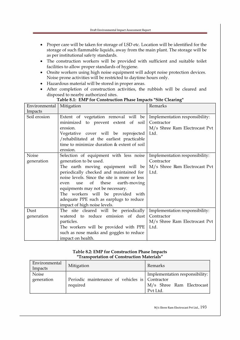
Draft Environmental Impact Assessment Report
M/s Shree Ram Electrocast Pvt Ltd., 193
• Proper care will be taken for storage of LSD etc. Location will be identified for the storage of such flammable liquids, away from the main plant. The storage will be as per institutional safe ty standards.
• The construction workers will be provided with sufficient and suitable toilet
facilities to allow proper standards of hygiene.
• Onsite workers using high noise equipment will adopt noise protection devices. Noise prone activities will be restricted to daytime hours only.
• Hazardous material will be stored in proper areas.
• After completion of construction activities, the rubbish will be cleared and
disposed to nearby authorized sites.Table 8.1: EMP for Construction Phase Impacts "Site Clearing"
EnvironmentalImpacts
Mitigation Remarks
Soil erosion Extent of vegetation removal will be
minimized to prevent extent of soil
erosion.Vegetative cover will be reprojected
/rehabilitated at the earliest practicable
time to minimize duration & extent of soilerosion.
Implementation responsibility:
Contractor
M/s Shree Ram Electrocast Pvt Ltd.
Noise
generation
Selection of equipment with less noise
generation to be used.
The earth moving equipment will be
periodically checked and maintained for noise levels. Since the site is more or less even use of these earth-moving
equipments may not be necessary.
The workers will be provided withadequate PPE such as earplugs to reduce
impact of high noise levels.
Implementation responsibility:
Contractor
M/s Shree Ram Electrocast Pvt
Ltd.
Dust
generation
The site cleared will be periodically
watered to reduce emission of dustparticles.
The workers will be provided with PPE
such as nose masks and goggles to reduce
impact on health.
Implementation responsibility:
ContractorM/s Shree Ram Electrocast Pvt
Ltd.
Table 8.2: EMP for Construction Phase Impacts"Transportation of Construction Materials”
EnvironmentalImpacts
Mitigation Remarks
Noisegeneration Periodic maintenance of vehicles is
required
Implementation responsibility: Contractor
M/s Shree Ram Electrocast
Pvt Ltd.

Draft Environmental Impact Assessment Report
M/s Shree Ram Electrocast Pvt Ltd., 194
Dust generation Construction materials will becovered with tarpaulin sheets to
prevent the material from being air
borne.
The vehicle speed will be regulated.The workers transporting materials
will be provided with PPE such as
nose masks to reduce impact of air
borne dust on their health
Implementation responsibility: Contractor
M/s Shree Ram Electrocast
Pvt Ltd.
Vehicularemissions
Periodic emission check for vehicles is required.
Clean fuel will be used for vehicles.
Implementation responsibility: Contractor
M/s Shree Ram Electrocast
Pvt Ltd.
Table 8.3: EMP for Construction Phase Impacts "Construction Activities”
EnvironmentalImpacts
Mitigation Remarks
Noisegeneration
Personnel Protective Equipment (PPE)such as ear plugs and helmets will be
provided for construction workers.
The working hours will be imposed on
construction workers.
Implementationresponsibility:
Contractor
M/s Shree Ram
Electrocast Pvt Ltd.Dust generation PPE in the form of nose masks will be
provided for construction workers.
Use of water sprays to prevent the dust
Contractor from being air borne.
Implementation
responsibility:
Contractor
M/s Shree RamElectrocast Pvt Ltd.
Air Emissions
from
constructionmachinery
Periodic check and regular maintenance
of construction machinery for emissions
Clean fuel will be used in equipments
Implementation
responsibility:
ContractorM/s Shree Ram
Electrocast Pvt Ltd.
8.2.1 Water Resources and Quality
Following mitigation measures will be adopted to avoid impact on water resources
• Construction equipment requiring minimum water for cooling and operation for optimum effectiveness will be chosen
• High pressure hose will be used for cleaning and dust suppression purposes.
• Water harvesting measures would be taken.
• Appropriate sanitation facilities, septic tank and soak pits will be provided for
the workers onsite and offsite to reduce impact on water resources. Regular
maintenance will be done during the entire life cycle.
• No discharge of construction wastes to surface water bodies or ground water will be allowed during construction.
Draft Environmental Impact Assessment Report
M/s Shree Ram Electrocast Pvt Ltd., 195
• Efforts will be made for reuse of water and its conservation.During Construction period in rainy season, the water quality is likely to be affected due to the construction work and loosening of topsoil. This is likely to increase the
suspended solids in the run – off during heavy precipitation. In order to reduce the
impact on water quality, temporary sedimentation tanks will be constructed for the settlement of the suspended matter. However, it is envisaged that the monsoon period
will be avoided for cutting and filling of earthwork. Additionally, following measures
will be taken to avoid the surface water pollution.
• Soil binding and fast growing vegetation grass would be grown around the construction site before commencement of construction activity to reduce soil
erosion;
• Appropriate sanitation facilities will be provided for the construction workers to
reduce impact on ground water resources and also to maintain hygienicconditions.
There is no likely hood of ground water contamination, as no waste will be discharged
to ground water bodies during construction. However sewage generated during the
construction phase will be treated in the Septic Tank and Soak Pit. Wherever
construction wastes need to be disposed off on land or off- site, the same will be disposed off in a proper manner and permission will be taken from the concerned
statutory authorities.
8.2.2 Air Quality
During Construction period, there is likelyhood of generation of dust and NOx
emission. This can be attributed to leveling activity and vehicular movement. Thetransport vehicles using petrol or diesel will be properly maintained to minimize smoke
in the exhaust. Since, there is likelihood of fugitive dust from the construction activity,
water sprinkling will be done. In addition to this following measures will be taken
during the construction phase to reduce the impact on the air quality.• Any vehicle not meeting the vehicular pollution standards will not be allowed
within the construction activity.
• Water will be sprayed by high-pressure water hoses during dust generating
construction activities e.g. excavation, crushing/demolishing, concrete mixing,material handling etc. to suppress dust; and
• Vehicles delivering loose and fine materials like sand and fine aggregates will be
covered by tarpaulin to reduce spills on roads.
• The height from which excavated materials are dropped will be controlled to a minimum practical height to limit fugitive dust generation from unloading.
• The random Ambient Air Quality Monitoring will be done to ensure that the
significant impacts are being mitigated adequately.
8.2.3 Noise Level
Draft Environmental Impact Assessment Report
M/s Shree Ram Electrocast Pvt Ltd., 196
The popul ation in nearby villages from the proposed site are located at a distance of 4-5Kms away. Hence, the noise impact on the surrounding population during the
construction phase will be within the acceptable limits. High noise generation
equipment, if used will be operated during the daytime only and completely restricted
during night hours and this eliminates any possible discomfort to the nearbycommunities. Community noise levels are not likely to be affected because of the
vegetation and likely attenuation due to the physical barriers.
The following recommendations will be implemented:
• Provision of insulating caps and ads at the exit of noise source on the machinery;
• Construction equipment generating minimum noise and vibration be chosen:
• The use of damping materials such as thin rubber / lead sheet for wrapping the
work places line compressors, generators sets.
• Shock absorbing techniques will be adopted to reduce impact;
• Inlet and outlet mufflers will be provided which are easy to design;
• Ear muffs will be provided to the workers and it will be enforced to be used by
the workers; and• Greenbelt will be developed along the periphery of the proposed site.
• Ambient Noise Level Monitoring will be conducted at suitable location at
periodic intervals during construction phase to conform to the stipulated
standards both during day and night time.
8.2.4 Solid /Hazardous Waste Management
The hazardous materials used during the construction may include petrol, diesel,
Welding gas and paints. These materials will be stored and handled according to the KSPCB guidelines.
• Diesel and other fuels will be stored in separate enclosures;
• Wherever possible, hazardous raw materials to be substituted by non- hazardous
materials, e.g. Cleaning solvent can be replaced with film –free biodegradable cleaners. Usage of non chlorinated strippers instead of strippers containing
methylene chloride and substitution of water based paint for oil based ones;
• Separate storage of waste paints, thinners, contaminated rags and brushes will be adopted.
• Vehicle maintenance area to be designed to prevent contamination of ground
water by accidental spillage of oil
8.2.5 Site Security
Adequate security arrangement will be made to ensure that the local inhabitants and the
stray cattle are not exposed to the potentials hazards of construction activities. The proposed site is barricaded with suitable fencing preventing the entry of unauthorized
persons, vehicular movements and stray animals.
8.2.6 Traffic Pattern

Draft Environmental Impact Assessment Report
M/s Shree Ram Electrocast Pvt Ltd., 197
Heavy vehicular movement will be restricted to daytime only and adequate parkingfacility will be provided. The speed of all vehicular movements will be controlled
through proper monitoring and by movement of vehicles only in demarcated routes.
8.2.7 Solid Waste Generation
• The solid waste generated during the construction phase is usually Excavated
earth material and Construction debris.
• Excavated earth material will be reused for backfilling between foundations; to
fill up the low-lying areas and whereas, topsoil will be reused forLandscaping/Greenbelt development purpose.
• Construction debris as far as possible will be reused / recycled for back filling / sub base work for roads & pavements and excess will be transported to nearby
authorized disposal sites.8.2.8 Ecological Aspects
• Plantation of dust absorbing trees and shrubs near the dust generating areas.
• Plantation of soil binding plants e.g. grass will be carried out to avoid soilerosion.
• Plantation of noise attenuating species to reduce noise pollution both during the
construction as well as in the operation stage.
• Stabilization of all disturbed slopes before the onset of monsoon to avoid soil erosion.
• Cutting of existing trees/bushes/ other vegetation will be avoided as for as
possible or will be minimized.
• Operation of high noise producing equipment will be avoided during night time to avoid impact on the immediate vicinity of the proposed project site
surroundings.
• Use of best available construction technology to minimize impacts on flora and fauna of the project site area.
8.2.9 Aesthetics
• Existing aesthetics of the site will be tried to maintain by taking appropriate
measures in different activities.
• Existing peaceful environment will be maintained in the vicinity of the project site.
• The excavated material dump will not be permitted to become a major visual
feature of the local landscape. The height of the dump will not exceed the mature tree top level in the area.
8.2.10 Socio-Economic
• Local people from nearby villages will be employed for construction work to the maximum extent possible.
• Proper facilities for domestic water supply and sanitation services will be made
available to the construction workers at the site.
8.2.11 facilities provided for labour force during construction
Facilities provided for workers during the construction phase include the following:

Draft Environmental Impact Assessment Report
M/s Shree Ram Electrocast Pvt Ltd., 198
• About 200 construction workers will be employed in the construction site.
• 7 Toilets, 5 Urinals and 5 Bathrooms will be provided for the laborers.
• First Aid facilities will be provided at the site.
• Local Doctor will be assigned for regular health check – up of theconstruction workers
• Arrangement with local hospitals for any emergency measures will be
made for all the laborers working at site
• Safety measures like PPE (Personal Protective Equipments) - Helmets, Safetyshoes, Nose Mask, Goggles, and Safety Belts, etc will be provided for the
construction laborers during construction, depending on the nature of their work.
• About 15 KLD of drinking water will be arranged through private tankers
conforming to IS drinking water quality standards
8.3 Operation stage
8.3.1 Air EnvironmentM/s Shree Ram Electrocast Pvt Ltd. proposes to expand pig iron plant, Captive power
plant and DIP plant, and establish Sinter plant, coke oven plant, slag cement grinding
unit in the existing plant premises which consists of pig Iron plant and Captive Power Plant. Air emissions from the proposed industrial process mainly comprising melting of
various metallic raw materials in the furnace, flue gas from coke ovens, power plant,
and DIP plant and fugitive emission.
The mitigation measures needs to be adopted during the operation stage to control the negative impacts on air environment of the surrounding of the project area given below:
• Air preheater/BF stoves is the main pollution sources from Pig Iron plant. Gas
cleaning plant with venturi Scrubber are provided to control the pollutants in the
Blast furnace (BF) gas before distributon of the gas.
• Anneling furnace, MG treatment and zinc coating unit will be provided with stacks as stipulated by KSPCB norms.
• Magnesium converters and zinc coating units will be provided with Bag filters.
• Sinter plant will be connected to ESP to minimize the impact of air pollution.
• AFBC boiler will also be connected to ESP.
• Reducing emissions from sinter plant by process optimization, including
minimizing stoppages and maintaining consistent operation in terms of strand speed, bed composition (particularly consistent blending of reverts which should not contain oil), bed height, use of additions such as burnt lime; and keeping the
strand, ductwork, ESP and bag filter air tight
• Pollution reduction from coke making relies as much on techniques andoperation does equipment. Prevention of fugitive releases to air and accidental
releases water and land are heavily dependent on maintaining steady operation
of the well trained and motivated operating staff, management who use key
performance parameters in systematic monitoring and fault analysis (e.g.chimney and emissions, coke and flue temperatures and battery pre ssures in the
short battery average temperatures and emissions trends over the medium term)
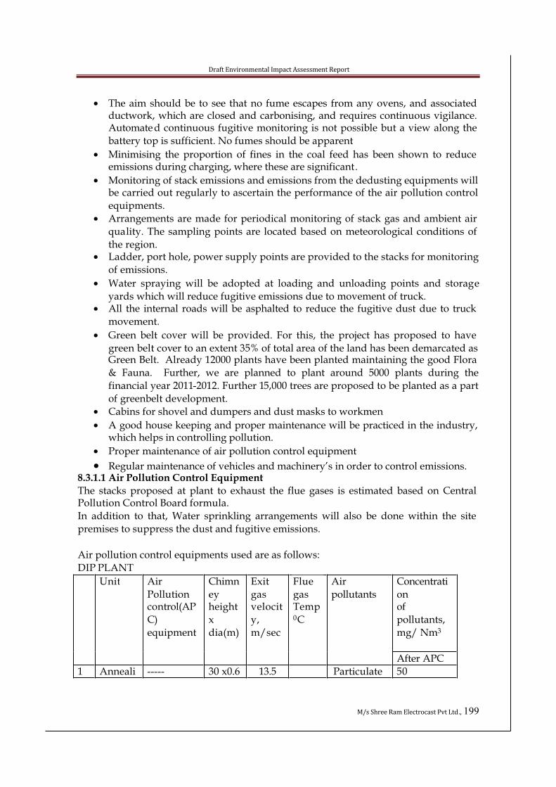
Draft Environmental Impact Assessment Report
M/s Shree Ram Electrocast Pvt Ltd., 199
• The aim should be to see that no fume escapes from any ovens, and associated ductwork, which are closed and carbonising, and requires continuous vigilance. Automated continuous fugitive monitoring is not possible but a view along the
battery top is sufficient. No fumes should be apparent
• Minimising the proportion of fines in the coal feed has been shown to reduce emissions during charging, where these are significant.
• Monitoring of stack emissions and emissions from the dedusting equipments will be carried out regularly to ascertain the performance of the air pollution control
equipments.
• Arrangements are made for periodical monitoring of stack gas and ambient air
quality. The sampling points are located based on meteorological conditions of
the region.• Ladder, port hole, power supply points are provided to the stacks for monitoring
of emissions.
• Water spraying will be adopted at loading and unloading points and storage
yards which will reduce fugitive emissions due to movement of truck.• All the internal roads will be asphalted to reduce the fugitive dust due to truck
movement.
• Green belt cover will be provided. For this, the project has proposed to have
green belt cover to an extent 35% of total area of the land has been demarcated as Green Belt. Already 12000 plants have been planted maintaining the good Flora
& Fauna. Further, we are planned to plant around 5000 plants during the
financial year 2011-2012. Further 15,000 trees are proposed to be planted as a part
of greenbelt development.
• Cabins for shovel and dumpers and dust masks to workmen
• A good house keeping and proper maintenance will be practiced in the industry, which helps in controlling pollution.
• Proper maintenance of air pollution control equipment
• Regular maintenance of vehicles and machinery’s in order to control emissions.8.3.1.1 Air Pollution Control Equipment
The stacks proposed at plant to exhaust the flue gases is estimated based on Central Pollution Control Board formula.
In addition to that, Water sprinkling arrangements will also be done within the site
premises to suppress the dust and fugitive emissions.
Air pollution control equipments used are as follows:
DIP PLANT
Concentrati
onof
pollutants,
mg/ Nm3
Unit Air
Pollutioncontrol(AP
C)
equipment
Chimn
eyheight
x
dia(m)
Exit
gasvelocit
y,
m/sec
Flue
gasTemp0C
Air
pollutants
After APC
1 Anneali ----- 30 x0.6 13.5 Particulate 50

Draft Environmental Impact Assessment Report
M/s Shree Ram Electrocast Pvt Ltd., 200
FBC Boiler Capacity- 2 x 54 TPH, 21 MWH
3 Sinter plant
Capacity-300,000 TPA
matter
SO2 15.3
ngFurnace
300-3500C
NO2 12.4
Particulatematter
50
SO2 15.4
2 MgConverter
Bag Filter 30 x0.6 14.5 1500C
NO2 9.4
3 ZincCoating
Bag Filter 30 x 0.5
14.0 400C Particulatematter
50
Concentratio
n of
pollutants,
mg/ Nm3
Unit Air
Pollution
control(AP
C)equipment
Chimney
height x Exit
dia.m
Exit gas
velocity
, m/sec
Flue
gas
Temp 0C
Air
pollutant
s
After APC
Particula
te matter
50
SO2 12.7
1 FBC boile
r
ESP 90 M
x 2.5m
16.0 1800C
NO2 14.2
Concentra
tion of pollutants
, mg/ Nm3
Unit Air
Pollutioncontrol
(APC)equipme
nt
Chimne
y height x Exit
dia. m
Exit gas
velocity,m/sec
Flue gas
Temp 0C
Air
pollutants
After
APC
Particulate
matter
45
SO2 15.7
1 Sinter M/c Head End
Exhaust-
Dedusting
system
ESP 30 M x 1.5
14.0100-
1600C
NO2 13.4
Particulate
matter
45
SO2 13.5
2 Sinter M/c Tail End Exhaust-
Dedusting
system
ESP 30 M x 1.5
14.0 900C
NO2 11.2
3 Fuel Crushing Bag 30 M x 400C Particu 45

Draft Environmental Impact Assessment Report
M/s Shree Ram Electrocast Pvt Ltd., 201
4. Coke Oven plant with waste heat recovery boilers (2)
5. Cement PlantCapaciy 100,000 TPA
dedustingsystem
Filter 0.5 latematter
4 Flux crushing
& screening
dedustingsystem
Bag
Filter
30 M x
0.4
6
6
400C Particu
late
matter
50
5 Cold sinter
screeningdedustingsystem
Bag
Filter
30 M x
0.4
6 400C Particu
latematter
50
Unit Air Pollution control(APC)
equipment
Chimneyheight
Exit gas velocity,
m/sec
Fluegas
Temp0C
Airpollutants
Concentrationof pollutants,
mg/ Nm3
Particulate
matter
78
SO2 20
1 Coke
Oven
batteries(2) with waste heat
recovery
boiler
N0.1
- 30 M x
1.5 m
8 1800C
NO2 8
Particulate
matter
78
SO2 20
2 Coke
Oven
batteries
(2) with waste heat
recovery
boiler
No.2
- 30 M x
1.5m
8 1800C
NO2 8
Concentration of
pollutants, mg/
Nm3
Unit Air
Pollution
control(APC)
equipment
Chimney
height x
dia m
Exit gas
velocity,
m/sec
Flue
gas
Temp0C
Air
pollutant
s
After APC
1 Dedusting
unit
Bag Filter 30 M x0.5 6 400C Particula
te matter
50

Draft Environmental Impact Assessment Report
M/s Shree Ram Electrocast Pvt Ltd., 202
6. Pig Iron plant at SREPL
*Present pig iron production capacity - 120,000 TPA
**Enhanced capacity- 200,000 TPA
Details of Stack and Gaseous Emissions (on Enhancement of Capacity)
BF gas fired
BoilerMBP/BF stoves Gas flare
ParameterAfter
enhancement**After enhancement** After enhancement**
Stack no. 1 2 3
Stack dia., m 1.24 2.01 0.75
Stack Height, m 30 30 30
Fuel,
B.F.gas,
Nm3/h
F.O., kg/hr
22 000
nil
28,000
NilNil
Emissions
Flue gasTemp. °C 320 -
Velocity of flue
gas15.8m 9.8 -
Pollutants, mg/
Nm3
SPM 50 50 -
SO2 40 40 -
NOx 10 10 -
8.3.1.2 For Fugitive Dust control
Uncontrolled fugitive particulate emissions are associated with material handling
operations. These operations consist of unloading, storing, grinding / crushing and
sizing of coal, and screening, crushing, storing, and unloading of coke. Dry fog type dust suppression system will be installed in the coal preparation unit includingcrushers, screens, etc
Table 8.4: Characteristics of Secondary Fugitive EmissionsSl.
No.
Item Secondary fugitive Emissions Control Strategy
1) Leaking of PipeConnection
Iron Oxide, H2S, CO, NOx,SO2 etc
Weld together
2) Valves Iron Oxide, H2S, CO, NOx,
SO2 etc
Seal-less Design
3) Fans, Compressors Iron Oxide, H2S, SO2, NOx
and other
Closed vent system Dual
mechanical seal
4) Raw material Iron oxide, fine particles of Binding agent in the
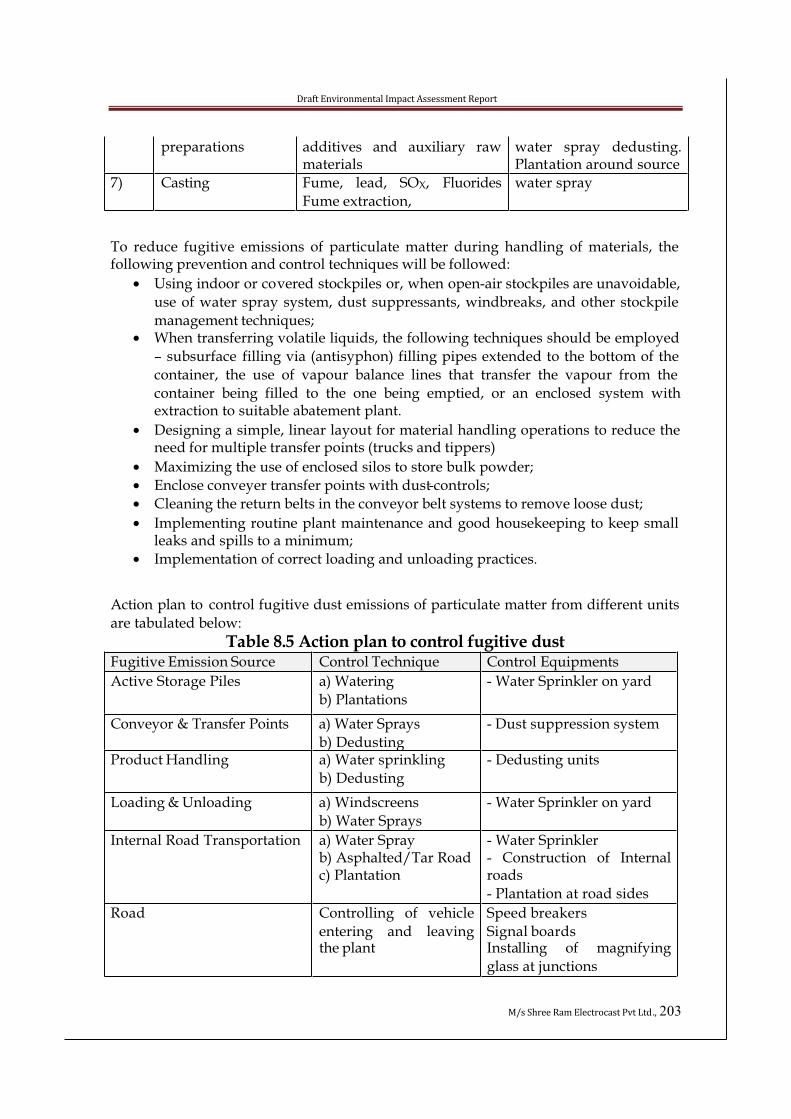
Draft Environmental Impact Assessment Report
M/s Shree Ram Electrocast Pvt Ltd., 203
preparations additives and auxiliary rawmaterials
water spray dedusting.Plantation around source
7) Casting Fume, lead, SOX, Fluorides
Fume extraction,
water spray
To reduce fugitive emissions of particulate matter during handling of materials, the following prevention and control techniques will be followed:
• Using indoor or covered stockpiles or, when open-air stockpiles are unavoidable,
use of water spray system, dust suppressants, windbreaks, and other stockpile
management techniques;• When transferring volatile liquids, the following techniques should be employed
– subsurface filling via (antisyphon) filling pipes extended to the bottom of the
container, the use of vapour balance lines that transfer the vapour from the
container being filled to the one being emptied, or an enclosed system withextraction to suitable abatement plant.
• Designing a simple, linear layout for material handling operations to reduce the need for multiple transfer points (trucks and tippers)
• Maximizing the use of enclosed silos to store bulk powder;
• Enclose conveyer transfer points with dust-controls;
• Cleaning the return belts in the conveyor belt systems to remove loose dust;
• Implementing routine plant maintenance and good housekeeping to keep small leaks and spills to a minimum;
• Implementation of correct loading and unloading practices.
Action plan to control fugitive dust emissions of particulate matter from different units
are tabulated below:
Table 8.5 Action plan to control fugitive dustFugitive Emission Source Control Technique Control Equipments
Active Storage Piles a) Watering
b) Plantations
- Water Sprinkler on yard
Conveyor & Transfer Points a) Water Sprays
b) Dedusting
- Dust suppression system
Product Handling a) Water sprinkling
b) Dedusting
- Dedusting units
Loading & Unloading a) Windscreens
b) Water Sprays
- Water Sprinkler on yard
Internal Road Transportation a) Water Sprayb) Asphalted/Tar Roadc) Plantation
- Water Sprinkler- Construction of Internalroads
- Plantation at road sides
Road Controlling of vehicle
entering and leavingthe plant
Speed breakers
Signal boardsInstalling of magnifying
glass at junctions
Draft Environmental Impact Assessment Report
M/s Shree Ram Electrocast Pvt Ltd., 204
8.3.2 Water PollutionAll water systems inside the plant are closed circuit system and there is no trade effluent
from the process.
8.3.2.1 Water Environment
Water requirement for the proposed project will be met from Tungabhadra River. The
water will be used majorly for cooling purposes. There is no effluent in this process.Therejected water if any will be neutralised and used for gardening. The quantity of canteen
wastewater generated and domestic wastewater generated from toilet and bathrooms
will be treated in the STP of capacity 50 KLD and the treated effluent will be reused for Greenbelt Development.Apart from the proposed treatment schemes, following additional measures will
minimize operational impacts:
• There is no effluent water in this process
• Use of high pressure hoses for area cleaning• House maintenance and floor wash wastewater will be reused after treatment.
• No wastewater will be discharged to any ground water or to the surface water body.
• Storm water drains will be provided to avoid flooding in the proposed project
site area and provision will be made for runoff get diverted to recharge pits with
pre oil and grease trap there by increasing the groundwater table.
• No water will be drawn during lean season. Excess water will be drawn and stored during rainy season and that will be used during lean season.
8.3.2.2 Water Pollution Control and Conservation
Extensive recycling has been adopted in the design of plant water systems. Quality of circulating water will be maintained through dosing of conditioning chemicals forcontrolling corrosion, scale deposit and microbial growth.
The raw water from River will be pumped to reservoir. This water will pass through
filters, softner and demineraliser plants . The treated water will be use for manufacturing process.
Through cascaded reuse of blow down, the water scheme ensures practically zero-
discharge from the industrial water circuits
8.3.2.3 Water pollution control
Water pollution mainly comprises of inorganic solids, oil, grease, etc. in suspension,
solution and emulsion.
The pollutants present in the waste water will be reduced to acceptable levels by
adoption of the following schemes.

Draft Environmental Impact Assessment Report
M/s Shree Ram Electrocast Pvt Ltd., 205
• Re-circulating water in the process whereby discharged volume is considerablyreduced
• Close circuit cooling wherever feasible.
• Clarifier and sludge pond for removal of suspended solids
• Neutralization of acidic water by lime
• Removal of oil and grease from the contaminated water by means of oil traps and
skimming devices
No Water is drawn from the river during lean seasons. During rainy season water is drawn and collected in the storage reservoir.
8.3.3 Noise Pollution
All steam outlets like safety valves; ejectors are connected with silencers and all fans are
being insulated with acoustic insulations. The maximum sound in the different areas is maximum 90 decibels, which is in the limit.
8.3.3.1 Noise Environment:
• Personnel working near noisy areas will be provided with adequate personal
protective equipment such as earplugs and earmuffs, use of which will be strictly enforced.
• Sophisticated and low noise generating equipments will be selected.
• Proper mounting of equipments and providing noise insulating enclosures or paddling where practicable.
• The equipments will be maintained at all times to ensure permissible noise levels.
• Appropriate advanced silencers, acoustic barriers; vibration-reducing pads will be provided for all noise generating equipments.
• The sources of continuous noise generating equipment such as compressors,
pumps etc will be designed to have noise level not exceeding 85-90dB(A).
• It would be ensured that there would not be any operator near the noise
generating equipments on continuous basis.
• Boundary walls and dense green belt will be erected to act as acoustic barriers.
• Adequate and appropriate type of green belt would be developed in and around the proposed project site for noise mitigation in the area.
• Shock absorbing techniques will be adopted to reduce noise level.
• Acoustical walls and roofs are provided to buildings where such machineries are installed.
• Proper maintenance of machineries especially oiling and greasing of bearing and gears etc.
• Use of personnel protective to persons working near noise creating locations.
• Plantation of green trees around the factory building and premises to control the
intensity of noise to the surrounding area.
• 35 % land area around the factory is covered with green belt. It includes green belt of 6 to 10 m width around storage yards.
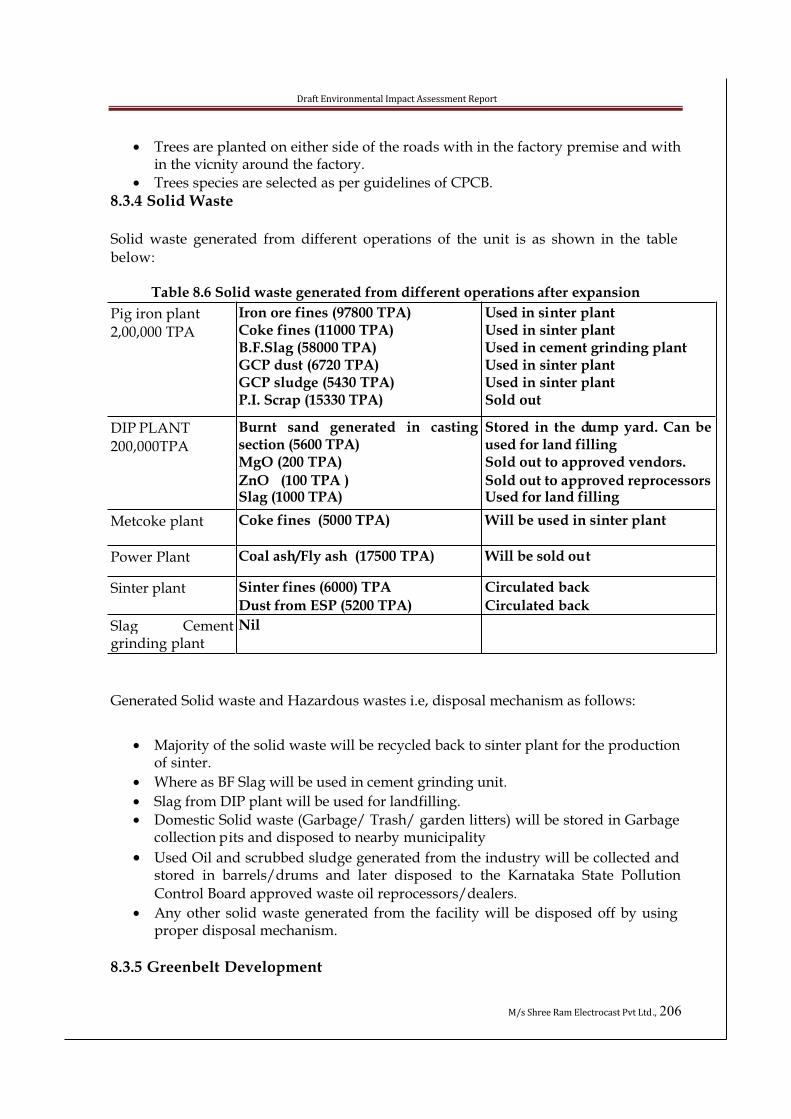
Draft Environmental Impact Assessment Report
M/s Shree Ram Electrocast Pvt Ltd., 206
• Trees are planted on either side of the roads with in the factory premise and with in the vicnity around the factory.
• Trees species are selected as per guidelines of CPCB.
8.3.4 Solid Waste
Solid waste generated from different operations of the unit is as shown in the table
below:
Table 8.6 Solid waste generated from different operations after expansion
Pig iron plant
2,00,000 TPA
Iron ore fines (97800 TPA) Coke fines (11000 TPA) B.F.Slag (58000 TPA) GCP dust (6720 TPA) GCP sludge (5430 TPA) P.I. Scrap (15330 TPA)
Used in sinter plant Used in sinter plant Used in cement grinding plant Used in sinter plant Used in sinter plant Sold out
DIP PLANT
200,000TPA
Burnt sand generated in castingsection (5600 TPA)MgO (200 TPA)
ZnO (100 TPA )Slag (1000 TPA)
Stored in the dump yard. Can be used for land fillingSold out to approved vendors.
Sold out to approved reprocessorsUsed for land filling
Metcoke plant Coke fines (5000 TPA) Will be used in sinter plant
Power Plant Coal ash/Fly ash (17500 TPA) Will be sold out
Sinter plant Sinter fines (6000) TPA
Dust from ESP (5200 TPA)
Circulated back
Circulated back
Slag Cementgrinding plant
Nil
Generated Solid waste and Hazardous wastes i.e, disposal mechanism as follows:
• Majority of the solid waste will be recycled back to sinter plant for the production of sinter.
• Where as BF Slag will be used in cement grinding unit.
• Slag from DIP plant will be used for landfilling.
• Domestic Solid waste (Garbage/ Trash/ garden litters) will be stored in Garbage collection pits and disposed to nearby municipality
• Used Oil and scrubbed sludge generated from the industry will be collected and stored in barrels/drums and later disposed to the Karnataka State Pollution
Control Board approved waste oil reprocessors/dealers.
• Any other solid waste generated from the facility will be disposed off by using proper disposal mechanism.
8.3.5 Greenbelt Development
Draft Environmental Impact Assessment Report
M/s Shree Ram Electrocast Pvt Ltd., 207
Green belt is an important sink for air pollutants. Trees also absorb noise and byenhancing the green cover, improve the ecology and aesthetics and affect the local
micrometeorology. Trees also have major long-term impacts on soil quality and the
ground water table. By using suitable plant species, green belts can be developed in
strategic zones to provide protection from emitted pollutants and noise.In the proposed plant, green belt will be developed in vacant areas, around office
buildings, around stores, along the side of roads, along the plant’s boundaries and
around the waste dump area. Plant species suitable for green belts should not only be
able to flourish in the area but must also have rapid growth rate, evergreen habit, large crown volume and small / pendulous leaves with smooth surfaces. All these traits are
difficult to get in a single species. Therefore a combination of these is sought while
selecting trees for green belt.
As per provisions 35% of total area of the land has been demarcated as Green Belt.Already 12000 plants have been planted maintaining the good Flora & Fauna. Further,
we are planned to plant around 5000 plants during the financial year 2011-2012.
SRECPL also proposes to plant another 7000 saplings as a part of greenbelt
development. The species selected for greenbelt development will fulfill the following specific requirements of the area:
• Tolerate to specific conditions.
• Will have rapid growth rate.
• They will rich canopy and shielding property.
• Large bio-mass and leaves to provide fodder and fuel.
• Ability to improve wastelands/barren areas.
• As for as possible all be native in nature.
• Greenbelt development plan and tree species proposed is enclosed as Annexure -5
8.3.5.1 Action plan for development of Greenbelt in 35% area
o Greenbelt is defined as the mass plantation of pollution tolerant trees and shrubs
in an area for the purpose of minimizing air pollution by filtering, intercepting and absorbing pollutants in an effective manner for improve of the Environment.
o The proposed project plans to develop and maintain 35% of Greenbelt of the total plot area within its Industrial premises.
o Hence for the same, a standard horticulture practice will be followed whileplanting saplings in pits of dimension 1000mm X 1000mm X 1000mm for
large/big trees and 600mm X 600mm X 600mm for smaller trees and shrubs.
o A three tier system will be followed in order to develop a canopy type greenbelt.
Therefore, the plantation order will follow shrubs, smaller trees and larger trees from inside towards the boundary wall.
o Special care will be taken for planting shrubs or trees along the road side. The
height (1000mm-1500mm for shrubs and 3000mm-5000mm for trees) and the foliage areas will be such that it does not affect the visibility.
o Local native plant species tolerant to local climatic conditions and tree species
that retain foliage longest and attract birds will be preferred for Greenbelt
Development.
Draft Environmental Impact Assessment Report
M/s Shree Ram Electrocast Pvt Ltd., 208
o The development of the greenbelt will be in parallel with the constructionactivities of the project and will be maintained effectively during operation phase
of the project too.
o Greenbelt development plan is enclosed as Annexure and Species to be planted is
also enclosed.
8.3.6 Storm Water Management
Shree Ram Electrocast Pvt Ltd is planning to have a system of rainwater harvesting at plant. Rainwater harvesting is primarily dependent on various site characteristics suchas soil properly, catchments characteristics; rainfall characteristic, and ground water
table etc. There are artificial as well as natural rainwater harvesting system.
Construction of rainwater filter bed at centralized place where water from individualunit as well as storm water from open area will be diverted. The rainwater carries
suspended solids as washed out from open area. A filter bed filters the particles thus
prevent them from reaching / contaminating ground water. The first layer of filter bed
will be coarse sand the second layer will be pebbles and third layer will be gravel. The filtrate thus collected from the bottom of filter bed will be piped to recharge bed.
o Storm water gutters will be constructed in the premises.
o Garland channels will be provided to the storage yards.
o Storm water storage capacity will be provided for about 30% of the annual storm water collected from the factory premises.
o The rain water thus collected is used for greenery development in the factory.
o Also, part of storm water thus collected can also be used as a source of water for
the industry.o Storm water drains will be provided within the premises of the industry to avoid
mixing with affluent.
o Storm water drains will be provided on both sides of the roads. Rectangular
drains will be provided based on the quantity of storm water to be conveyed and
depth limitations.o Rainwater harvesting tank of 2 lakh capacity will be constructed.
o 40 recharge pits are provided for the purpose of ground water recharge.
Typical section of recharge pits are shown below:

Dra
ft E
nv
iro
nm
en
tal
Imp
act
Ass
ess
me
nt
Re
po
rt
M/
s S
hre
e R
am
Ele
ctro
cast
Pv
t L
td.,
20
9
Fig
ure
8.1
Se
ctio
n R
ech
arg
e p
it
SC
AL
EN
TS
2000
2000
XX
'
DEPTH AS PER SITE CONDITION

Draft Environmental Impact Assessment Report
M/s Shree Ram Electrocast Pvt Ltd., 210
8.3.7 Ecological Aspects The following measures are proposed to have minimum impact on ecology of theproject area:
o Continuing greening efforts in and around the project site.o Conservation of existing vegetation and afforestation covering larger areas near
and around existing project area. o The dump yard is treated by a gentle gradient and pitching will be done all
around the earthen heap will be formed into terraces and it will be stabilized by planting grass sets and also by sowing grass seeds.
8.3.8 Aesthetics Aspects o The entire area will be planted with local tree species of aesthetic value, fodder
value, fruit bearing and birds attracting tree species. Hence it would beconverted into a possible park for the nearby villages and project staff forrecreation.
8.3.9 Socio Economic Aspects
Following are the activities conducted and proposed around the premises
• The project is not going to cause significant damage to the existing agricultural situation. Instead, it is likely to provide the farmers with supplementary income.
• The project has very strong positive employment and income effects.• There is a great possibility of industrialization in the vicinity of the proposed
steel plant. This is likely to bring dramatic changes by transforming thisbackward area into an industrially developed one.
• The project has very strong positive impact, which is likely to result in theimprovement of economic situation of Siruguppa
• Overall peoples’ perception on the project is a mix of advantages anddisadvantages. On one hand, they expect job opportunities, market expansion etc. as advantages and on the other hand they are worried about the damage to agriculture.
• As an impact of identification of the project, small-scale industrial economy is likely to flourish in the surrounding area. The small-scale industrial units are expected to get financial supports from the financial institutions and banks. In this way, an overall development may take place in this area.
• The process of development will have maximum impact on the lifestyle of the local people. The project and the consequent peripheral industrial economy will generate income to the local and migrated people which will increase theaggregate demand. This demand will get realized in the market and finally, lead to the market in the locality of the project. Market expansion supported byexpected infrastructural developments like roads, electricity, water supply etc. will result in improving the economic development in the entire region.
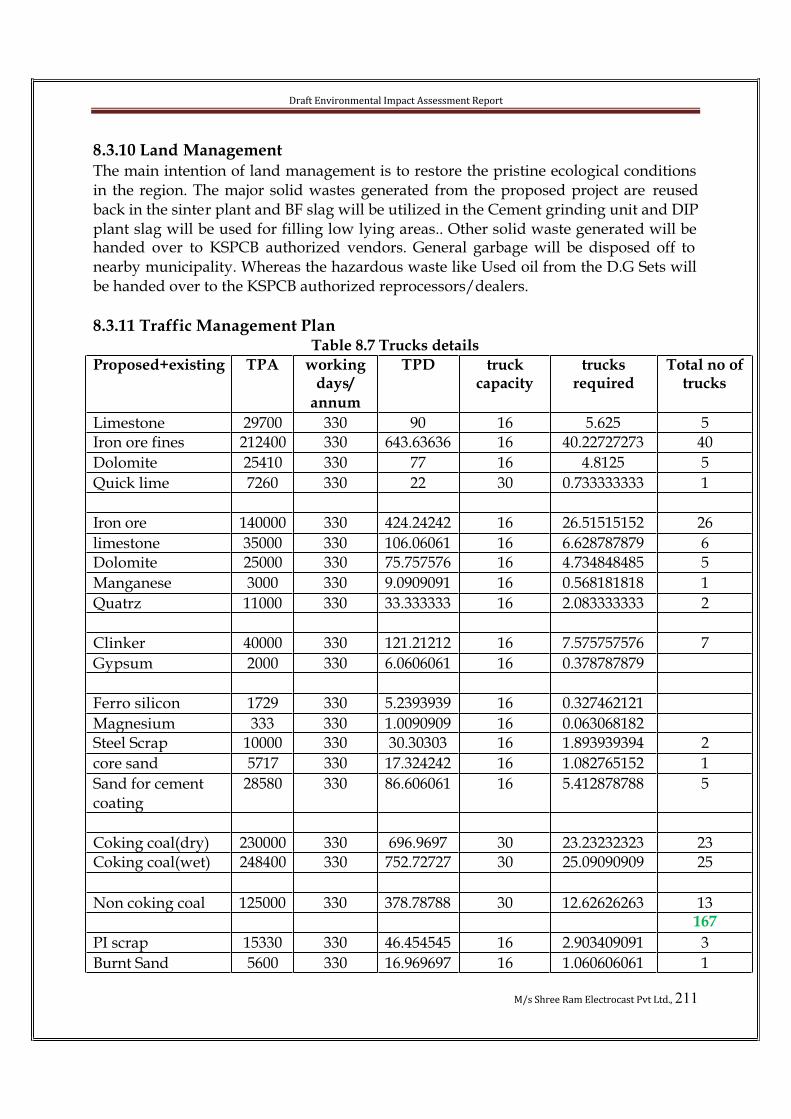
Draft Environmental Impact Assessment Report
M/s Shree Ram Electrocast Pvt Ltd., 211
8.3.10 Land ManagementThe main intention of land management is to restore the pristine ecological conditions in the region. The major solid wastes generated from the proposed project are reusedback in the sinter plant and BF slag will be utilized in the Cement grinding unit and DIP plant slag will be used for filling low lying areas.. Other solid waste generated will be handed over to KSPCB authorized vendors. General garbage will be disposed off to nearby municipality. Whereas the hazardous waste like Used oil from the D.G Sets will be handed over to the KSPCB authorized reprocessors/dealers.
8.3.11 Traffic Management PlanTable 8.7 Trucks details
Proposed+existing TPA workingdays/
annum
TPD truckcapacity
trucksrequired
Total no of trucks
Limestone 29700 330 90 16 5.625 5Iron ore fines 212400 330 643.63636 16 40.22727273 40
Dolomite 25410 330 77 16 4.8125 5
Quick lime 7260 330 22 30 0.733333333 1
Iron ore 140000 330 424.24242 16 26.51515152 26
limestone 35000 330 106.06061 16 6.628787879 6Dolomite 25000 330 75.757576 16 4.734848485 5
Manganese 3000 330 9.0909091 16 0.568181818 1
Quatrz 11000 330 33.333333 16 2.083333333 2
Clinker 40000 330 121.21212 16 7.575757576 7
Gypsum 2000 330 6.0606061 16 0.378787879
Ferro silicon 1729 330 5.2393939 16 0.327462121
Magnesium 333 330 1.0090909 16 0.063068182Steel Scrap 10000 330 30.30303 16 1.893939394 2
core sand 5717 330 17.324242 16 1.082765152 1
Sand for cement coating
28580 330 86.606061 16 5.412878788 5
Coking coal(dry) 230000 330 696.9697 30 23.23232323 23Coking coal(wet) 248400 330 752.72727 30 25.09090909 25
Non coking coal 125000 330 378.78788 30 12.62626263 13167
PI scrap 15330 330 46.454545 16 2.903409091 3
Burnt Sand 5600 330 16.969697 16 1.060606061 1
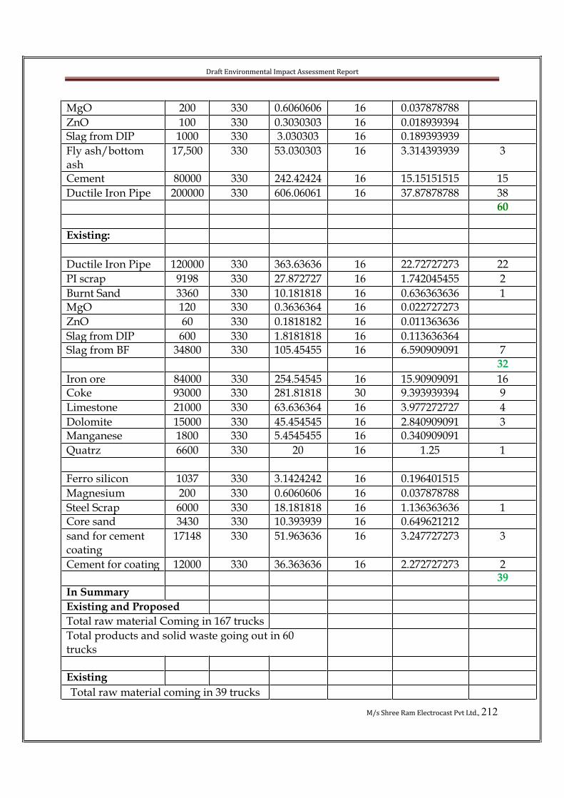
Draft Environmental Impact Assessment Report
M/s Shree Ram Electrocast Pvt Ltd., 212
MgO 200 330 0.6060606 16 0.037878788
ZnO 100 330 0.3030303 16 0.018939394Slag from DIP 1000 330 3.030303 16 0.189393939
Fly ash/bottom ash
17,500 330 53.030303 16 3.314393939 3
Cement 80000 330 242.42424 16 15.15151515 15
Ductile Iron Pipe 200000 330 606.06061 16 37.87878788 3860
Existing:
Ductile Iron Pipe 120000 330 363.63636 16 22.72727273 22
PI scrap 9198 330 27.872727 16 1.742045455 2
Burnt Sand 3360 330 10.181818 16 0.636363636 1MgO 120 330 0.3636364 16 0.022727273
ZnO 60 330 0.1818182 16 0.011363636
Slag from DIP 600 330 1.8181818 16 0.113636364Slag from BF 34800 330 105.45455 16 6.590909091 7
32
Iron ore 84000 330 254.54545 16 15.90909091 16Coke 93000 330 281.81818 30 9.393939394 9
Limestone 21000 330 63.636364 16 3.977272727 4
Dolomite 15000 330 45.454545 16 2.840909091 3Manganese 1800 330 5.4545455 16 0.340909091
Quatrz 6600 330 20 16 1.25 1
Ferro silicon 1037 330 3.1424242 16 0.196401515
Magnesium 200 330 0.6060606 16 0.037878788
Steel Scrap 6000 330 18.181818 16 1.136363636 1Core sand 3430 330 10.393939 16 0.649621212
sand for cement coating
17148 330 51.963636 16 3.247727273 3
Cement for coating 12000 330 36.363636 16 2.272727273 239
In Summary
Existing and Proposed
Total raw material Coming in 167 trucks
Total products and solid waste going out in 60 trucks
Existing
Total raw material coming in 39 trucks

Draft Environmental Impact Assessment Report
M/s Shree Ram Electrocast Pvt Ltd., 213
Total products and solid going out in 32 trucks
Proposed
expansion
Raw material coming in 128 trucks/day 8trucks/hr
Product and solid waste going out 28 trucks/day
2truck/hr
Total no of trucks/hr is 10Total No of trucks per hour due to expansion is= 10 trucks
Considering the existing scenario as explained in Chapter-III, and traffic due toexpansion is minimum.
8.4 Existing Environmental Management plan8.4.1 Wastewater
i. The effluent generation from the proposed project is nilii. Storm water drains are linked to storm water reservoir.
iii. Re-circulated cooling water collected in the neutralization tank and used forgardening.
8.4.2 Air EnvironmentAir environment is affected by gaseous emissions from boiler, coke ovens, DIP plant and blast furnace air preheater/ stoves in addition to fugitive emissions at different sources. These emissions include SPM, SO2 and NOx. Fugitive emissions are alsogenerated at solid handling locations in the plant. The following measures are adopted to control gaseous emissions and to prevent their adverse impact on the environment.
8.4.3 Stack Emissionsi. Chimney of adequate height are provided to boiler, flare, MBF air
preheater/stoves, coke ovens, sinter plant and diesel generator.ii. Arrangements are made for periodical monitoring of stack gas and ambient air
quality. The sampling points are located based on metrological conditions of the region.
iii. Ladder, porthole, power supply points are provided to the boiler and GCP stacks for monitoring of emissions.
iv. Gas Cleaning Plant and thickeners are operated continuously. Provision are be made for back-up power for this equipment.
v. Water spraying is practiced at loading and unloading points, storage yards and near solid waste dumping yards. Transport of material should be done incovered trucks only.
Draft Environmental Impact Assessment Report
M/s Shree Ram Electrocast Pvt Ltd., 214
vi. Green belt cover in the plant should be increased, especially in the direction of winds.
8.4.4 Fugitive Emission• Fugitive emissions within the factory and storage yards are controlled by good
house keeping, water spraying and sprinkling.• Tree plantation in 3 to 5 rows is developed all around raw material and solid
waste storage yards.• All internal roads are properly paved or tarred so as to avoid fugitive emissions.
A tree plantation in 2 to 3 rows is developed on either sides of the roads.• Measures will be taken to maintain all the roads used for transportation of raw
material and finished goods.• Water spraying practice should be continued at loading and unloading points,
storage yards and near solid waste dumping yards.• All the internal roads leading to the sites, should be asphalted to reduce the
fugitive dust due to truck movement.8.4.5 Noise EnvironmentSome units in the plant have noisy operations such as compressors, boiler fans, steamturbine, and D.G. sets. The exposure of workers to the noise of high level will bereduced with appropriate measures. Noise from major equipments will be within 85 dB(A) at 1 m from source and at 1.2 m height. Noise and its adverse impacts will be reduced by incorporating suitable measures in the industry. Acoustic enclosures are provided to the DG sets and air compressors to control the noise.
Safety Measures Against Noise Level
The predominant noise levels will be confined to the work zones in the plant. Noiselevels felt at surrounding villages are not significant as compared to background noise. This will be further attenuated by vegetation. Major noise generating areas are blower house and D.G. set house. Various measures proposed to reduce the noise pollution includes, reduction of noise at source and provision of acoustic lagging for equipment. In some areas where due to technological process, it is not feasible to bring down the noise level within acceptable limits, personnel working in the areas is provided with noise reduction aid such as earmuff and also the duration of exposure of the personnel will be limited as per the norms. Necessary measures as indicated below are taken to reduce the sound intensity below the allowable limits at the source itself in the industry. In general at the locations of turbines, compressors, fans etc, the sound intensitygenerally exceeds the limit. The workers engaged in such locations are provided with earmuffs to have additional safety against noise nuisance.
• Adoption of noise reduction measures the construction of the industry as per the I.S. 3408-1965.
• Specifying the noise standards to the manufacturers of machineries• The use of damping materials for wrapping the work places like MBF platform,
MBP heaters. DG set, etc.
Draft Environmental Impact Assessment Report
M/s Shree Ram Electrocast Pvt Ltd., 215
• Shock absorbing techniques are adopted to reduce noise level at machinery generating high noise.
• Acoustical walls and roofs are provided to buildings where such machineries are installed.
• Proper maintenance of machineries especially oiling and greasing of bearing and gears etc.
• Use of personnel protective to persons working in such locations.• Plantation of green trees around the factory building and premises to control the
intensity of noise to the surrounding area.• Effective equipment maintenance like periodic lubrication, replacement of
bearings and de-dusting will be practiced. • It should be enforced on the workers to use earplugs in high noise areas. Noise
exposure to workers will not be allowed to exceed 80 dB (A) for 8hr shifts. With above noise abatement measures the noise level in the premise will be maintained with the desired limits. Further, noise level will be monitored to confirm the ambient noise level to the standards of industrial area and noise level outside project premise to the standards of residential areas.
8.4.6 Land ManagementThe main intention of land management is to restore the existing ecological conditions in the region. Solid waste storage yard are suitably prepared to avoid seepage ofleachate. Plantations are carried out all around the disposal area to arrest any fugitive emissions.
8.4.7 Green Belt DevelopmentDevelopment of greenbelt in and around industrial activity is an effective was to check pollutants and their dispersion in to surrounding areas. Plants act as natural sink for variety of air pollutants. These can help to reduce the pollutant level in the airenvironment. The degree of pollution attenuation by a green belt depends on its height and width, foliage surface area, density, dry deposition, velocity of pollutants and the average wind speed through the green belt. The main objective of green belt around the factory is:
i. Mitigation of impacts due to fugitive emissionsii. Attenuation of noise levels
iii. Ecological restorationiv. Improvement in aesthetic environment qualityv. Waste water reuse and re-cycling..
vi. Soil erosion preventionKeeping in view of the soil and water quality available in and around the project site and the topography of land, following species are considered for green beltdevelopment.Road side plantation
Avenue plantation include following species

Draft Environmental Impact Assessment Report
M/s Shree Ram Electrocast Pvt Ltd., 216
• Albizia lebbeck• Azadirachta indica• Tamarindus indica• Albizia Odoratissima• Leucaena Leucocephala• Mangifera indica• Bamboo• Almond tree• Pongamia pinnata• Acacia nilotica• Ber Plant• Prosophis gulflora
Around various shops
As there will be limited space (in height) due to various overhead pipelines. herefore,small and medium sized species are suggested and they should be planted depending on the vertical height available for plant growth.Small species
• Dodonaea viscosa• Cocoloba uvifera• Cassia auriculata
Medium size species
• Acacia Arabica
Around office and other buildings
Species suggested for plantation around office and other buildings are listed below.• Cassia siamea• Albezzia amera• Albezzia lebbeck• Cassis Javanica• Erythrina indica• Lagrestroemia flosreginea• Peltophorum feruginium• Delonix regia
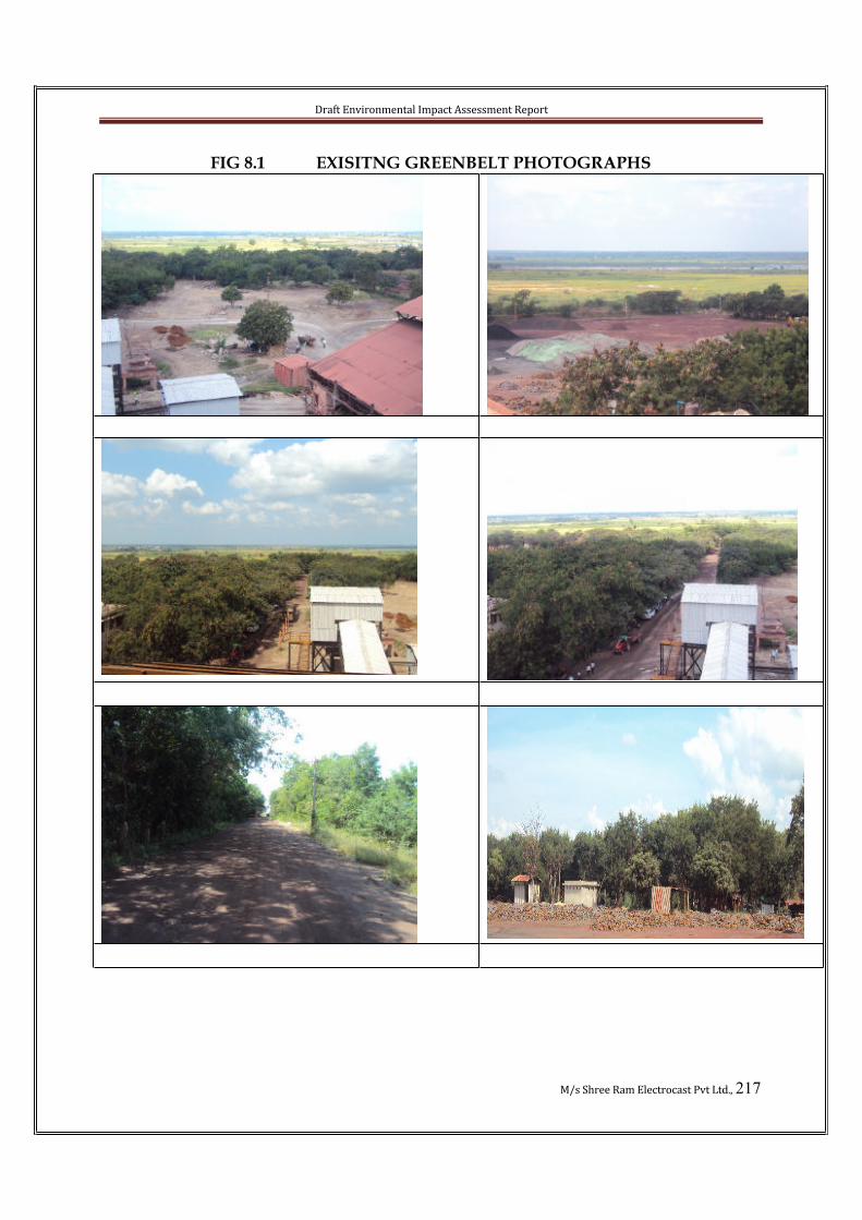
Draft Environmental Impact Assessment Report
M/s Shree Ram Electrocast Pvt Ltd., 217
FIG 8.1 EXISITNG GREENBELT PHOTOGRAPHS

Draft Environmental Impact Assessment Report
M/s Shree Ram Electrocast Pvt Ltd., 218
8.5 Conservation of Air, Water and Energy recovery
• Fugitive dust emission control by dry fogging and dust extraction system.• Fugitive emission control at raw materials storage and handling by land based
fume suppression system by sprinkling water.• Fugitive emissions control at Sinter Plant through feed material controls and
enclosures• Extraction of electric power from BF top gas.• Heat recovery in BF stoves.• Arresting fugitive dust emissions in MBF shop.• Reuse/recycling of treated wastewater.
Energy conservation measures: Energy conservation measures at the design stage are
equally important as pollution prevention and control measures, since the energyconsumption has a direct linkage to the emission of carbon dioxide, a green house gas. It is suggested that the energy conservation measures be adopted wherever possible to reduce the specific energy consumption. The incentives offered for energy conservation by the National and international bodies like CDM mechanism should be used toconserve energy.
Energy Saving through Sinter use
Use of sinter in BF burden improves productivity due to increased reactivity because of larger surface area that comes in contact with the upward rising gases. Higher productivity and reduction in coke consumption is linked with sinter use in BF which indirectly reduces CO2 emissions per ton of hot metal in the environment.Further, the contribution of Blast Furnace to CO2 emissions in an integrated steel plant is about 75%. Technologically, there is limited or marginal scope for CO2 reduction measures in the blast furnace. Since, sinter plant enhances BF productivity andreduction in coke rate, the Sinter Plant brings significant benefits for steel plantoperators in reducing CO2 emissions and thus protecting the environment.
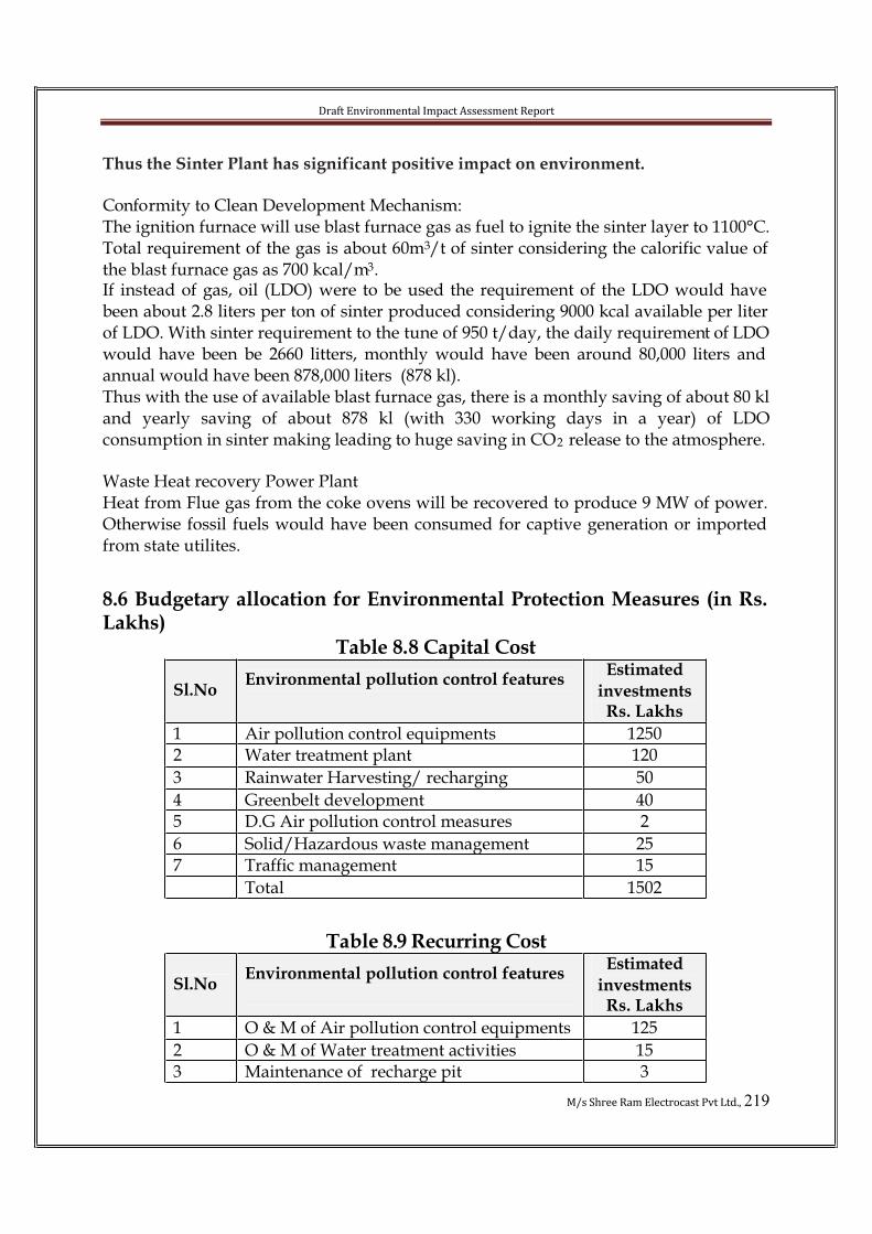
Draft Environmental Impact Assessment Report
M/s Shree Ram Electrocast Pvt Ltd., 219
Thus the Sinter Plant has significant positive impact on environment.
Conformity to Clean Development Mechanism:The ignition furnace will use blast furnace gas as fuel to ignite the sinter layer to 1100°C. Total requirement of the gas is about 60m3/t of sinter considering the calorific value of the blast furnace gas as 700 kcal/m3.If instead of gas, oil (LDO) were to be used the requirement of the LDO would have been about 2.8 liters per ton of sinter produced considering 9000 kcal available per liter of LDO. With sinter requirement to the tune of 950 t/day, the daily requirement of LDO would have been be 2660 litters, monthly would have been around 80,000 liters and annual would have been 878,000 liters (878 kl).Thus with the use of available blast furnace gas, there is a monthly saving of about 80 kl and yearly saving of about 878 kl (with 330 working days in a year) of LDOconsumption in sinter making leading to huge saving in CO2 release to the atmosphere.
Waste Heat recovery Power PlantHeat from Flue gas from the coke ovens will be recovered to produce 9 MW of power. Otherwise fossil fuels would have been consumed for captive generation or imported from state utilites.
8.6 Budgetary allocation for Environmental Protection Measures (in Rs. Lakhs)
Table 8.8 Capital Cost
Sl.NoEnvironmental pollution control features
Estimated
investmentsRs. Lakhs
1 Air pollution control equipments 12502 Water treatment plant 120
3 Rainwater Harvesting/ recharging 50
4 Greenbelt development 405 D.G Air pollution control measures 2
6 Solid/Hazardous waste management 257 Traffic management 15
Total 1502
Table 8.9 Recurring Cost
Sl.NoEnvironmental pollution control features
Estimated
investmentsRs. Lakhs
1 O & M of Air pollution control equipments 125
2 O & M of Water treatment activities 153 Maintenance of recharge pit 3
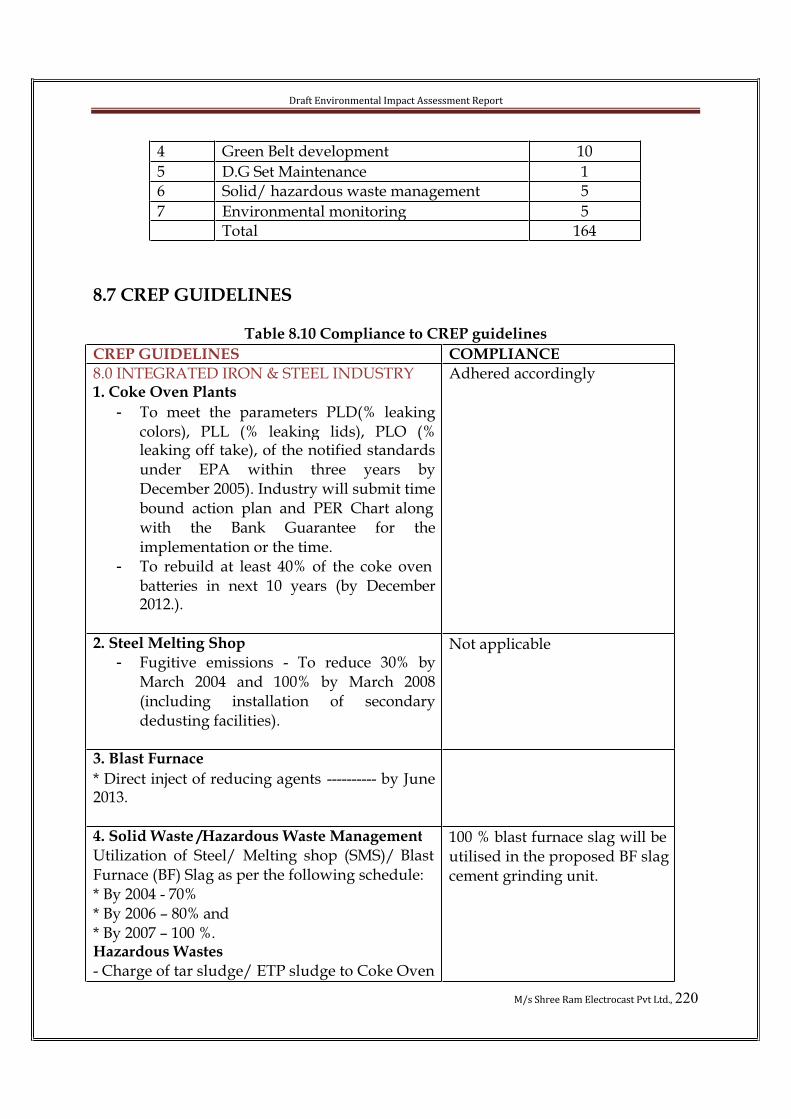
Draft Environmental Impact Assessment Report
M/s Shree Ram Electrocast Pvt Ltd., 220
4 Green Belt development 10
5 D.G Set Maintenance 16 Solid/ hazardous waste management 5
7 Environmental monitoring 5Total 164
8.7 CREP GUIDELINES
Table 8.10 Compliance to CREP guidelines
CREP GUIDELINES COMPLIANCE
8.0 INTEGRATED IRON & STEEL INDUSTRY1. Coke Oven Plants
- To meet the parameters PLD(% leakingcolors), PLL (% leaking lids), PLO (%leaking off take), of the notified standards under EPA within three years byDecember 2005). Industry will submit time bound action plan and PER Chart along with the Bank Guarantee for theimplementation or the time.
- To rebuild at least 40% of the coke oven batteries in next 10 years (by December2012.).
Adhered accordingly
2. Steel Melting Shop
- Fugitive emissions - To reduce 30% byMarch 2004 and 100% by March 2008(including installation of secondarydedusting facilities).
Not applicable
3. Blast Furnace
* Direct inject of reducing agents ---------- by June 2013.
4. Solid Waste /Hazardous Waste Management
Utilization of Steel/ Melting shop (SMS)/ Blast Furnace (BF) Slag as per the following schedule:* By 2004 - 70%* By 2006 – 80% and* By 2007 – 100 %.Hazardous Wastes
- Charge of tar sludge/ ETP sludge to Coke Oven
100 % blast furnace slag will be utilised in the proposed BF slagcement grinding unit.

Draft Environmental Impact Assessment Report
M/s Shree Ram Electrocast Pvt Ltd., 221
by June 2003. - Inventorization of the Hazardous waste as per Hazardous Waste (M& H), Rules, 1989 asamended in 2000 and implementation of theRules by Dec. 2003. ( tar sludge, acid sludge,waste Lubricating oil and type fuel falls in the category of Hazardous waste).
Adhered Accordingly
5. Water Conservation/ Water Pollution
- To reduce specific water consumption to 5 m3/tfor long products and 8 m3/t for flat products by December 2005.- To operate the Co-BP effluent treatment plant efficiently to achieve the notified effluentdischarge standards. – by June 2003.
Existing water consumption1200 KLD (PIG Iron plant-500KLD, DIP Plant- 700 KLD) Proposed plant requirement2215 KLDTotal water requirement afterexpansion = 3415 KLD.
6. Installation of Continuous stacks monitoring system & its calibration in major stacks andsetting up of the online ambient air qualitymonitoring stations by June 2005.
Environmental monitoring will be outsourced to KSPCBapproved Laboratory.
7. To operate the existing pollution controlequipment efficiently and to keep proper record of run hours, failure time and efficiency withimmediate effect. Compliance report in thisregard be submitted to CPCB/SPCB every three months.
Adhered accordingly
8. To implement the recommendations of Life
Cycle Assessment (LCA) study sponsored by
MoEF by December 2003.
Adhered accordingly
9. The industry will initiate the steps to adopt the following clean technologies measures to
improve the performance of industry towards production, energy land environment.
- Energy recovery of top Blast Furnace (BF) gas.
- Use of Tar- free runner linings.- De- dusting of Cast house at tap holes,
runners, skimmers ladle and chargingpoints.
- Suppression of fugitive emissions usingnitrogen gas or other inert gas
- To study the possibility of slag and fly ash transportation back to the abandoned
BF gas will be utilized in power plant
Dedusting facilities will beprovided.
Fugitive dust will besuppressed using watersprinklers.Slag and fly ash will be utilized
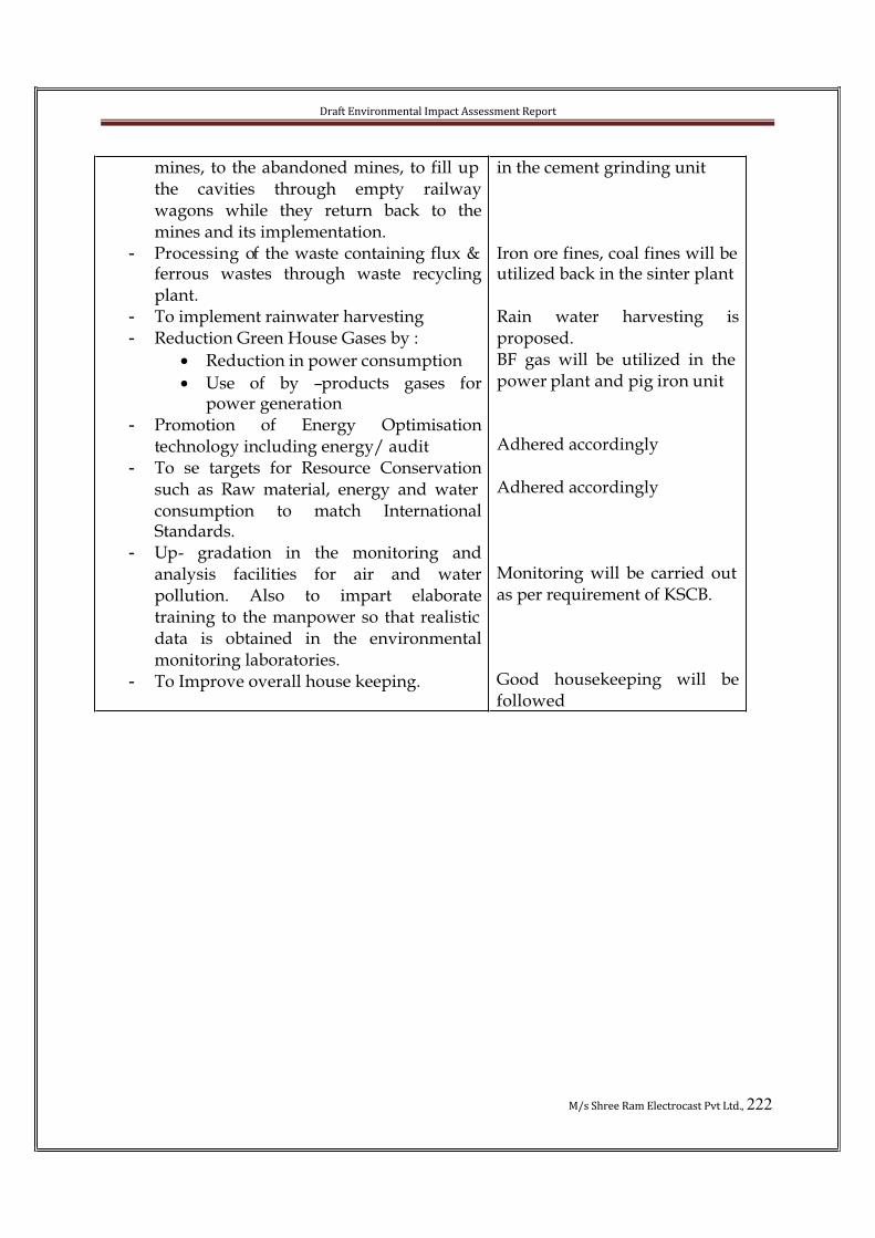
Draft Environmental Impact Assessment Report
M/s Shree Ram Electrocast Pvt Ltd., 222
mines, to the abandoned mines, to fill up the cavities through empty railwaywagons while they return back to themines and its implementation.
- Processing of the waste containing flux & ferrous wastes through waste recyclingplant.
- To implement rainwater harvesting- Reduction Green House Gases by :
• Reduction in power consumption
• Use of by –products gases forpower generation
- Promotion of Energy Optimisationtechnology including energy/ audit
- To se targets for Resource Conservationsuch as Raw material, energy and water consumption to match InternationalStandards.
- Up- gradation in the monitoring andanalysis facilities for air and waterpollution. Also to impart elaboratetraining to the manpower so that realistic data is obtained in the environmentalmonitoring laboratories.
- To Improve overall house keeping.
in the cement grinding unit
Iron ore fines, coal fines will be utilized back in the sinter plant
Rain water harvesting isproposed.BF gas will be utilized in the power plant and pig iron unit
Adhered accordingly
Adhered accordingly
Monitoring will be carried out as per requirement of KSCB.
Good housekeeping will befollowed

Draft Environmental Impact Assessment Report
M/s Shree Ram Electrocast Pvt Ltd., 223
CHAPTER-IX SUMMARY AND CONCLUSION
CHAPTER-1 INTRODUCTIONCompany Profile
Shree Ram Electro Cast Pvt. Ltd., was incorporated on 12th August, 2004 having
registered office 8 Camac Street Shanti Niketan Building 9th Floor Room No. 8 Kolkata-17, West Bengal. Directors of the company are Mr Mukesh Bhandari, Mr. ShaileshBhandari, Mr. Avinash Bhandari and Mr R K Purohit.
Existing Manufacturing Facilities
Unit Capacity Location
Pig Iron Plant
Captive Power Plant
120,000 TPA
2.5MW
Honarhalli, Hatcholi Post, Sirguppa Talluk, BellaryDistrict, Karnataka
Project profile:
After successful operation of existing steel Plant and power plant at Honarhalli, Post –Hatcholi, Taluk- Siruguppa, Dist.- Bellary and keeping in view growth potential in the steel sectors, the promoters had decided to set up a Ductile Iron Pipe plant of 120,000 TPA as value addition project and obtained the MOEF clearance (vide No J-11011/498/2010-IA-II (I) dated 22nd June 2011). This project is in the implementation phase.Now it is proposed to modernize the Pig Iron Plant to improve the fuel efficiency and capacity from 120,000 TPA to 200,000 TPA and set up the Coke Oven Plant, Expand the Ductile Iron Pipe plant from 120,000 TPA to 200,000 TPA, Sinter Plant, Cementgrinding plant and Captive Power Plant at the existing Site for production ofMetallurgical coke, D.I. Pipe, Sinter, Slag cement and Power. Due to total integration, the proposed project would improve the overall profitability of the project making it financially more viable. The proposed project envisages the followings manufacturing facilities:-
Proposed Project Details
Sl.No Items Particulars
1 Objective of theProject
• Expansion of Pig Iron Plant from 1,20,000 to 2,00,000 TPA
• Coke Oven Plant - 1,60,000 TPA
• Captive Power Plant - 30 MW
• Expansion of Ductile Iron Pipe Plant
from 1,20,000 to 2,00,000 TPA
• Sinter Plant– 3,00,000 TPA
• Cement Grinding Plant – 1,00,000TPA

Draft Environmental Impact Assessment Report
M/s Shree Ram Electrocast Pvt Ltd., 224
2 Promoters M/s. Shree Ram Electro cast Pvt. Ltd.
3 Investment forExpansion
415 Crores
4 Project location Sy.No.s 80, 81/A3, 95/A1, 95/A3, 96/A1, 96/A3,
97/1, 97/3, 98/A/1A, 98/A/1B, 98/A3, 98/B1, 98/B3, 98/C1,98/C3, 98/D1, 98/D3, 99, 100, 103, 104, 105and 106 of Honnarahalli Village and Sy,
No57/C/1, 57/D/1, 57/A/1A, 57/A/2A,57/A/3A, 57/B/A, 57/A/4A., 77/A, 77/B, 78/Aand 78/B of Halkote Village, Post – Hatcholi,
Taluk- Siruguppa, Dist.- Bellary, Karnataka -583 114
5 Extent of land The land available with SREPL is 114.97 acres.
Proposed additional land to be acquired through KIADB is 25.42 acres.
6 Category ofProject
A
7 Water demandand Source
Existing water consumption 1200 KLD (PIG Iron plant-500 KLD, DIP Plant- 700 KLD)Proposed plant requirement 2215 KLD
Total water requirement after expansion = 3415 KLD.Source: Tungabhadra river. Withdrawalpermission for 4150 KLD for the expansion
seeking from Government. (Order No: CI 57 SPI 2011, Bangalore Dated 25.02.2011.)
8 Power demand 26000 KVA after expansion
Environmental settings around the proposed project site (Within 10 kms radius)
Sl. No Feature Particulars
1. Location Honnarahalli village, Siruguppa taluk, district, Karnataka.
2. Present land use Industrial and agricultural land
3. Altitude above mean MSL 475 m
4. Temp.0C (Range) Max. 31.0 to 41.2 and Min. 10.7 to 20.6

Draft Environmental Impact Assessment Report
M/s Shree Ram Electrocast Pvt Ltd., 225
5. Mean Annual humidity & RF
65 % and 645 mm
6. Soil type Black cotton mixed loamy soil
7. Topography Plain terrain sloping towards NW
8. Nearest State Highway S.H.-19(Srirangapatna - Bidar), 8.2 km,
9. Nearest railway station None with in 10 km radius (Adoni-36.4 km in NE direction(S.C. Railway)
10. Nearest airport None with in 10 km radius. Bellary air strip; 63 kms (S) Hyderabad air port is about 227 km in NE.
11. Nearest village Honnarahalli, 1.4 km. in N
12. Nearest town Siruguppa 13.5 km, SW
13. Nearest major city None with in 10 km radius, Bellary, 66.4 km, SW
14. Nearest river Tungabhadra river , 1.8 Km , NW
15. Nearest industry None with in 10 km radius, Siruguppa Sugar 12 km.
16. Sensitive locations No Archeological structures, Historical places, ProtectedForests, Sanctuaries and Biosphere Reserves present within 10 kms from the Industry.

Draft Environmental Impact Assessment Report
M/s Shree Ram Electrocast Pvt Ltd., 226
CHAPTER-2 PROJECT DESCRIPTIONMODERNISATION OF PIG IRON PLANT
In oreder to modernize the pig iron plant the following units will be installed:
• Hot blast stoves
• Pulverised coal injection system • Oxygen injection unit
• Steam Injection unit
COKE OVEN PLANT
Shree Ram Electrocast Pvt Ltd plans to set-up a heat recovery type stamp chargedcoking plant to produce about 160,000 tons of gross coke per year and to generate electricity by making use of the waste flue gas from coking plant. The production facilities will contain coal preparation plant, coking plant and coke screening plant and waste heat recovery boilers.
CAPTIVE POWER PLANT
The Waste heat recovery boilers will utilize the latent heat of the flue gas from the coke ovens. AFBC boiler will utilize non coking coal for firing in the boiler. The coalrequirement will be 125,000 TPA or equivalent. The power generation capacity will 30 MW.
DUCTILE IRON PIPE PLANT
Hot metal received from blast furnace is charged along with steel scrap and ferro alloys. Magnesium is added The ductile iron pipes are made using centrifugal casting machineand heat treatment is carried out in annealing furnace. Zinc coating, pressure testing, cement mortar lining and bituminous coating will be carried out.
SINTER PLANT
Sintering is a technology for agglomeration of iron ore fines into useful Blast Furnace burden material. The raw materials used in sinter plant are - Iron ore fines (-10 mm), coke breeze (-3 mm), Lime stone & dolomite fines (-3mm) and other metallurgicalwastes. The proportioned raw materials are mixed and moistened in a mixing drum. The mix is loaded on sinter machine. The top surface of the mix is ignited throughstationary burners at approximately 1200 0C. Sinter is produced as a combined result of locally limited melting, grain boundary diffusion and recrystallisation of iron oxides. On the completion of sintering process, finished sinter cake is crushed and cooled.
Cement grinding unit
The raw materials Clinker and Granulated Slag are stocked in separate hoppers. These are discharged from the hopper with the help of two table feeders to the belt conveyor.

Draft Environmental Impact Assessment Report
M/s Shree Ram Electrocast Pvt Ltd., 227
Gypsum is added and all the materials are properly mixed and through a feeder materials are charged into the ball mill for grinding into powder form. The product is packed and sold out.
CHAPTER-3.0 BASELINE ENVIRONMENTAL SCENARIO
Environm
ental
Attributes
No of
LocationsObservations
Meteorolo
gy
1 Hourly observations for Temperature, Relative
Humidity, Wind direction, wind speed & Rain fall
during 3 month study period
AAQ 8 For all the parameters as per National Ambient Air
Quality Standards, 2009 for 24 hours duration, 2 times
in each week during 12-week study period
Water 9 3 Surface water Locations
6 Ground water locations (including the place near to
the plant site)
Parameters that are analyzed are as per Analysis of
Drinking Water Quality had been carried out
Noise 6 Day and night noise levels once in every location
Soil 05 At 5 locations.
Ecology Flora-Fauna
& Ecosystem
Total study period is 90days. However predicted flora
– fauna also included for non-seasonal plant species
(ephemerals) based on existing secondary data and
field conditions
Land use 10 km radius
study area
Land use data based and satellite imagery data of the
10 km study area.
Socio- Demography Secondary data from the existing literature (Census

Draft Environmental Impact Assessment Report
M/s Shree Ram Electrocast Pvt Ltd., 228
economic
data
&Occupation
al details
2001)
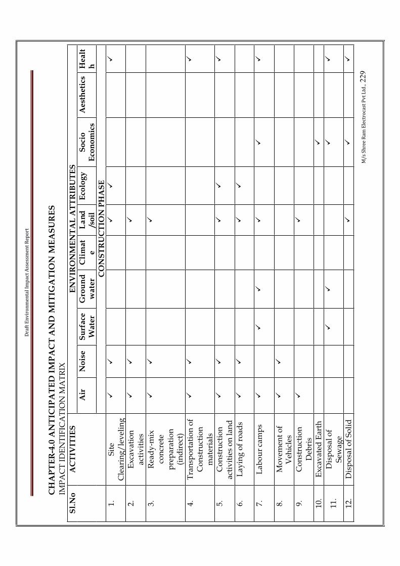
Dra
ft E
nv
iro
nm
en
tal
Imp
act
Ass
ess
me
nt
Re
po
rt
M/
s S
hre
e R
am
Ele
ctro
cast
Pv
t L
td.,
22
9
CH
AP
TE
R-4
.0 A
NT
ICIP
AT
ED
IM
PA
CT
AN
D M
ITIG
AT
ION
ME
AS
UR
ES
IMP
AC
T I
DE
NT
IFIC
AT
ION
MA
TR
IX
EN
VIR
ON
ME
NT
AL
AT
TR
IBU
TE
S
Air
No
ise
Su
rfa
ceW
ate
rG
rou
nd
wa
ter
Cli
ma
te
La
nd
/so
ilE
colo
gy
So
cio
Eco
no
mic
sA
est
he
tics
He
alt
h
Sl.
No
AC
TIV
ITIE
S
CO
NS
TR
UC
TIO
N P
HA
SE
1.S
ite
Cle
arin
g/
lev
elin
g
��
��
�
2.E
xca
vat
ion
act
ivit
ies
��
�
3.R
ead
y-m
ixco
ncr
ete
pre
par
atio
n(i
nd
irec
t)
��
�
4.T
ran
spo
rtat
ion
of
Co
nst
ruct
ion
mat
eria
ls
��
�
5.C
on
stru
ctio
nac
tiv
itie
s o
n l
and
��
��
�
6.L
ayin
g o
f ro
ads
��
��
7.L
ab
ou
r ca
mp
s�
��
��
�
8.M
ov
emen
t o
f V
ehic
les
��
9.C
on
stru
ctio
nD
ebri
s
��
10.
Ex
cav
ated
Ear
th�
11.
Dis
po
sal
of
Sew
age
��
��
12.
Dis
po
sal
of
So
lid
�
��
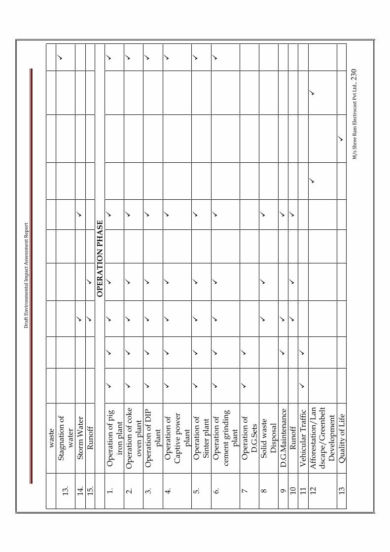
Dra
ft E
nv
iro
nm
en
tal
Imp
act
Ass
ess
me
nt
Re
po
rt
M/
s S
hre
e R
am
Ele
ctro
cast
Pv
t L
td.,
23
0
was
te
13.
Sta
gn
atio
n o
f w
ate
r�
14.
Sto
rm W
ater
��
15.
Ru
no
ff�
�
OP
ER
AT
ION
PH
AS
E
1.O
per
atio
n o
f p
ig
iro
n p
lan
t
��
��
��
2.O
per
ati
on
of
cok
e o
ven
pla
nt
��
��
��
3.O
per
atio
n o
f D
IP
pla
nt
��
��
��
4.O
per
atio
n o
f C
apti
ve
po
wer
p
lan
t
��
��
��
5.O
per
atio
n o
f S
inte
r p
lan
t
��
��
��
6.O
per
atio
n o
f ce
men
t g
rin
din
g
pla
nt
��
��
��
7O
per
atio
n o
f D
.G.S
ets
��
8S
oli
d w
aste
D
isp
osa
l
��
�
9D
.G.M
ain
ten
ance
��
�
10R
un
off
��
�
11V
ehic
ula
r T
raff
ic�
�
12A
ffo
rest
atio
n/
Lan
dsc
ape/
Gre
enb
elt
Dev
elo
pm
ent
��
13Q
ual
ity
of
Lif
e�

Dra
ft E
nv
iro
nm
en
tal
Imp
act
Ass
ess
me
nt
Re
po
rt
M/
s S
hre
e R
am
Ele
ctro
cast
Pv
t L
td.,
23
1
CH
AR
AC
TE
RIS
TIC
S O
F E
NV
IRO
NM
EN
TA
L I
MP
AC
TS
FR
OM
CO
NS
TR
UC
TIO
N A
CT
IVIT
IES
Imp
act
ch
ara
cteri
stic
sA
ctiv
ity
En
vir
on
me
nta
l
Att
rib
ute
sC
ause
Na
ture
Du
rati
on
Rev
ersi
bil
ity
Sig
nif
ica
nce
Air
En
vir
on
men
tD
islo
dg
ing
of
pa
rtic
les
fro
m t
he
gro
un
dD
irec
t,N
egat
ive
Sh
ort
-Ter
mR
ever
sib
leM
ediu
m
No
ise
En
vir
on
men
tN
ois
e g
ener
atio
n f
rom
ea
rth
ex
cav
atin
g
equ
ipm
ent
Dir
ect,
Neg
ativ
eS
ho
rt-
Ter
mR
ever
sib
leM
ediu
m
Lan
d u
se/
So
il
En
vir
on
men
tE
xca
va
tio
nD
irec
t,N
egat
ive
Lo
ng
Ter
mIr
rev
ersi
ble
Hig
h
Eco
log
yR
emo
val
of
veg
etat
ion
or
loss
of
flo
raD
irec
t,N
egat
ive
Sh
ort
- T
erm
Rev
ersi
ble
Med
ium
Sit
e cl
eari
ng
/L
evel
ing
act
ivit
ies
Hea
lth
Dis
lod
gin
g o
f p
art
icle
s (S
PM
/R
SP
M)
fro
m t
he
gro
un
d
Dir
ect,
Neg
ativ
eS
ho
rt-
Ter
mR
ever
sib
leM
ediu
m
Air
En
vir
on
men
tD
islo
dg
ing
of
pa
rtic
les
fro
m t
he
gro
un
dD
irec
t,N
egat
ive
Sh
ort
-ter
mR
ever
sib
leM
ediu
m
No
ise
En
vir
on
men
tN
ois
e g
ener
atio
n f
rom
ea
rth
ex
cav
atin
g
equ
ipm
ent
Dir
ect,
Neg
ativ
eS
ho
rt-
Ter
mR
ever
sib
leM
ediu
m
Lan
d u
se/
So
il
En
vir
on
men
tE
xca
va
tio
nD
irec
t,N
egat
ive
Lo
ng
Ter
mIr
rev
ersi
ble
Hig
h
Ex
cav
atio
nA
ctiv
itie
s
Hea
lth
Dis
lod
gin
g o
f p
art
icle
s (S
PM
/R
SP
M)
fro
m t
he
gro
un
d
Dir
ect,
Neg
ativ
eS
ho
rt-
Ter
mR
ever
sib
leM
ediu
m
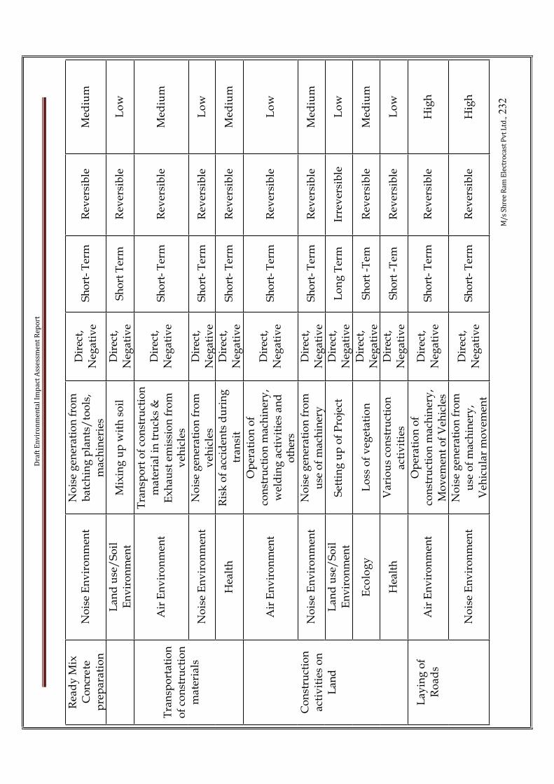
Dra
ft E
nv
iro
nm
en
tal
Imp
act
Ass
ess
me
nt
Re
po
rt
M/
s S
hre
e R
am
Ele
ctro
cast
Pv
t L
td.,
23
2
Rea
dy
Mix
C
on
cre
tep
rep
ara
tio
n
No
ise
En
vir
on
men
tN
ois
e g
ener
atio
n f
rom
bat
chin
g p
lan
ts/
too
ls,
mac
hin
erie
s
Dir
ect,
Neg
ativ
eS
ho
rt-
Ter
mR
ever
sib
leM
ediu
m
Lan
d u
se/
So
il
En
vir
on
men
tM
ixin
g u
p w
ith
so
ilD
irec
t,N
egat
ive
Sh
ort
Ter
mR
ever
sib
leL
ow
Air
En
vir
on
men
t
Tra
nsp
ort
of
con
stru
ctio
n
mat
eria
l in
tru
cks
&
Ex
hau
st e
mis
sio
n f
rom
v
ehic
les
Dir
ect,
Neg
ativ
eS
ho
rt-
Ter
mR
ever
sib
leM
ediu
m
No
ise
En
vir
on
men
tN
ois
e g
ener
atio
n f
rom
v
ehic
les
Dir
ect,
Neg
ativ
eS
ho
rt-
Ter
mR
ever
sib
leL
ow
Tra
nsp
ort
atio
no
f co
nst
ruct
ion
mat
eria
ls
Hea
lth
Ris
k o
f ac
cid
ents
du
rin
g
tran
sit
Dir
ect,
Neg
ativ
eS
ho
rt-
Ter
mR
ever
sib
leM
ediu
m
Air
En
vir
on
men
t
Op
erat
ion
of
con
stru
ctio
n m
ach
iner
y,
wel
din
g a
ctiv
itie
s an
d
oth
ers
Dir
ect,
Neg
ativ
eS
ho
rt-
Ter
mR
ever
sib
leL
ow
No
ise
En
vir
on
men
tN
ois
e g
ener
atio
n f
rom
u
se o
f m
ach
iner
yD
irec
t,N
egat
ive
Sh
ort
- T
erm
Rev
ersi
ble
Med
ium
Lan
d u
se/
So
il
En
vir
on
men
tS
etti
ng
up
of
Pro
ject
Dir
ect,
Neg
ativ
eL
on
g T
erm
Irre
ver
sib
leL
ow
Eco
log
yL
oss
of
veg
eta
tio
nD
irec
t,N
egat
ive
Sh
ort
-Tem
Rev
ersi
ble
Med
ium
Co
nst
ruct
ion
act
ivit
ies
on
L
and
Hea
lth
Var
iou
s co
nst
ruct
ion
a
ctiv
itie
sD
irec
t,N
egat
ive
Sh
ort
-Tem
Rev
ersi
ble
Lo
w
Air
En
vir
on
men
tO
per
atio
n o
f co
nst
ruct
ion
mac
hin
ery
, M
ov
emen
t o
f V
ehic
les
Dir
ect,
Neg
ativ
eS
ho
rt-
Ter
mR
ever
sib
leH
igh
Lay
ing
of
Ro
ad
s
No
ise
En
vir
on
men
tN
ois
e g
ener
atio
n f
rom
u
se o
f m
ach
iner
y,
Veh
icu
lar
mo
vem
ent
Dir
ect,
Neg
ativ
eS
ho
rt-
Ter
mR
ever
sib
leH
igh
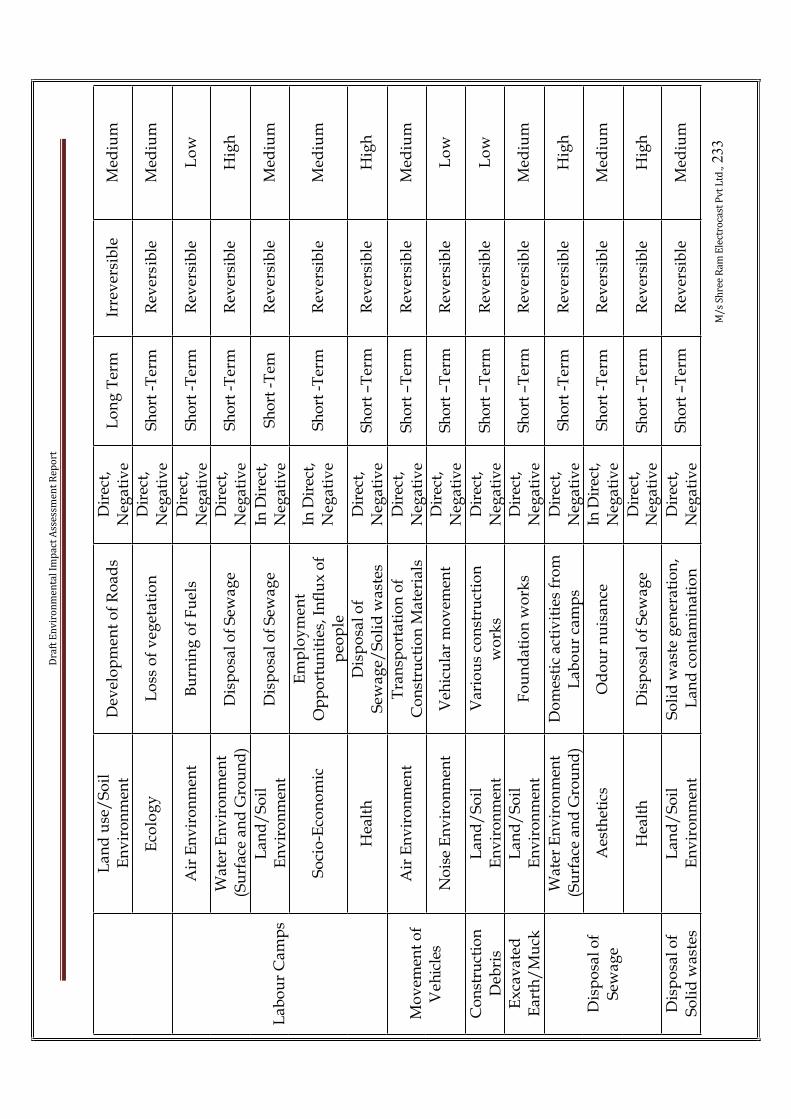
Dra
ft E
nv
iro
nm
en
tal
Imp
act
Ass
ess
me
nt
Re
po
rt
M/
s S
hre
e R
am
Ele
ctro
cast
Pv
t L
td.,
23
3
Lan
d u
se/
So
il
En
vir
on
men
tD
evel
op
men
t o
f R
oad
sD
irec
t,N
egat
ive
Lo
ng
Ter
mIr
rev
ersi
ble
Med
ium
Eco
log
yL
oss
of
veg
eta
tio
nD
irec
t,N
egat
ive
Sh
ort
-Ter
mR
ever
sib
leM
ediu
m
Air
En
vir
on
men
tB
urn
ing
of
Fu
els
Dir
ect,
Neg
ativ
eS
ho
rt-T
erm
Rev
ersi
ble
Lo
w
Wat
er E
nv
iro
nm
ent
(Su
rfac
e an
d G
rou
nd
)D
isp
osa
l o
f S
ewa
ge
Dir
ect,
Neg
ativ
eS
ho
rt-T
erm
Rev
ersi
ble
Hig
h
La
nd
/S
oil
En
vir
on
men
tD
isp
osa
l o
f S
ewa
ge
InD
irec
t,N
egat
ive
Sh
ort
-Tem
Rev
ersi
ble
Med
ium
So
cio
-Eco
no
mic
Em
plo
ym
ent
Op
po
rtu
nit
ies,
In
flu
x o
f p
eop
le
InD
irec
t,N
egat
ive
Sh
ort
-Ter
mR
ever
sib
leM
ediu
m
Lab
ou
r C
amp
s
Hea
lth
Dis
po
sal
of
Sew
age/
So
lid
was
tes
Dir
ect,
Neg
ativ
eS
ho
rt–T
erm
Rev
ersi
ble
Hig
h
Air
En
vir
on
men
tT
ran
spo
rtat
ion
of
Co
nst
ruct
ion
Mat
eria
lsD
irec
t,N
egat
ive
Sh
ort
–Ter
mR
ever
sib
leM
ediu
mM
ov
emen
t o
f V
eh
icle
sN
ois
e E
nv
iro
nm
ent
Veh
icu
lar
mo
vem
ent
Dir
ect,
Neg
ativ
eS
ho
rt–T
erm
Rev
ersi
ble
Lo
w
Co
nst
ruct
ion
Deb
ris
La
nd
/S
oil
En
vir
on
men
tV
ari
ou
s co
nst
ruct
ion
wo
rks
Dir
ect,
Neg
ativ
eS
ho
rt–T
erm
Rev
ersi
ble
Lo
w
Ex
cav
ated
Ear
th/
Mu
ckL
an
d/
So
ilE
nv
iro
nm
ent
Fo
un
dat
ion
wo
rks
Dir
ect,
Neg
ativ
eS
ho
rt–T
erm
Rev
ersi
ble
Med
ium
Wat
er E
nv
iro
nm
ent
(Su
rfac
e an
d G
rou
nd
)D
om
esti
c ac
tiv
itie
s fr
om
L
ab
ou
r ca
mp
sD
irec
t,N
egat
ive
Sh
ort
-Ter
mR
ever
sib
leH
igh
Aes
thet
ics
Od
ou
r n
uis
ance
InD
irec
t,N
egat
ive
Sh
ort
-Ter
mR
ever
sib
leM
ediu
mD
isp
osa
l o
f S
ewag
e
Hea
lth
Dis
po
sal
of
Sew
ag
eD
irec
t,N
egat
ive
Sh
ort
–Ter
mR
ever
sib
leH
igh
Dis
po
sal
of
So
lid
wa
stes
La
nd
/S
oil
En
vir
on
men
tS
oli
d w
aste
gen
erat
ion
,L
and
co
nta
min
atio
nD
irec
t,N
egat
ive
Sh
ort
–Ter
mR
ever
sib
leM
ediu
m

Dra
ft E
nv
iro
nm
en
tal
Imp
act
Ass
ess
me
nt
Re
po
rt
M/
s S
hre
e R
am
Ele
ctro
cast
Pv
t L
td.,
23
4
Aes
thet
ics
Od
ou
r n
uis
ance
InD
irec
t,N
egat
ive
Sh
ort
-Ter
mR
ever
sib
leM
ediu
m
Hea
lth
Deg
rad
atio
n o
f S
oli
d
was
te, a
ttra
ctio
n o
f fl
ies
Dir
ect,
Neg
ativ
eS
ho
rt–T
erm
Rev
ersi
ble
Med
ium
Sta
gn
atio
n o
f W
ate
rH
ealt
hM
osq
uit
o b
reed
ing
sit
esD
irec
t,N
egat
ive
Sh
ort
–Ter
mR
ever
sib
leH
igh
Wat
er E
nv
iro
nm
ent
(Su
rfac
e)C
on
stru
ctio
n s
ite
area
sD
irec
t,N
egat
ive
Sh
ort
-Ter
mR
ever
sib
leM
ediu
mS
torm
wat
er
Ru
n-o
ffL
an
d/
So
ilE
nv
iro
nm
ent
Flo
od
ing
Dir
ect,
Neg
ativ
eS
ho
rt–T
erm
Rev
ersi
ble
Hig
h

Dra
ft E
nv
iro
nm
en
tal
Imp
act
Ass
ess
me
nt
Re
po
rt
M/
s S
hre
e R
am
Ele
ctro
cast
Pv
t L
td.,
23
5
CH
AR
AC
TE
RIS
TIC
S O
F E
NV
IRO
NM
EN
TA
L I
MP
AC
TS
FR
OM
OP
ER
AT
ION
AL
PH
AS
E
Imp
act
char
acte
rist
ics
Act
ivit
yE
nv
iro
nm
en
tal
Att
rib
ute
sC
ause
Na
ture
Du
rati
on
Rev
ersi
bil
ity
Sig
nif
ica
nce
Air
En
vir
on
men
tO
per
atio
n o
f B
last
fu
rnac
eD
irec
t,N
egat
ive
Lo
ng
-T
erm
Rev
ersi
ble
Hig
hO
per
atio
n o
f P
ig
Iro
n p
lan
tN
ois
eE
nv
iro
nm
ent
Op
erat
ion
of
Bla
st
furn
ace
Dir
ect,
Neg
ativ
eL
on
g-
Ter
mR
ever
sib
leL
ow
Op
era
tio
n o
f co
ke
ov
en p
lan
tA
ir E
nv
iro
nm
ent
Op
era
tio
n o
f co
ke
ov
enD
irec
t,N
egat
ive
Lo
ng
-T
erm
Rev
ersi
ble
Hig
h
Air
En
vir
on
men
tO
per
atio
n o
f an
nea
lin
g f
urn
ace
Dir
ect,
Neg
ativ
eL
on
g-
Ter
mR
ever
sib
leL
ow
Op
erat
ion
of
DIP
p
lan
tN
ois
eE
nv
iro
nm
ent
Op
erat
ion
of
ann
eali
ng
fu
rnac
eD
irec
t,N
egat
ive
Lo
ng
-T
erm
Rev
ersi
ble
Lo
w
Air
En
vir
on
men
tO
per
ati
on
of
bo
iler
Dir
ect,
Neg
ativ
eL
on
g-
Ter
mR
ever
sib
leH
igh
Op
erat
ion
of
Po
wer
p
lan
tN
ois
eE
nv
iro
nm
ent
Op
era
tio
n o
f b
oil
erD
irec
t,N
egat
ive
Lo
ng
-T
erm
Rev
ersi
ble
Lo
w
Op
erat
ion
of
Cem
ent
gri
nd
ing
u
nit
Air
en
vir
on
men
tO
per
atio
n o
f g
rin
din
g
un
itD
irec
tn
eg
ati
ve
Lo
ng
-T
erm
Rev
ersi
ble
Hig
h
Op
erat
ion
of
sin
ter
pla
nt
Air
En
vir
on
men
tS
inte
rin
gD
irec
tn
egat
ive
Lo
ng
-T
erm
Rev
ersi
ble
Hig
h
Air
En
vir
on
men
tO
per
atio
n o
f D
.G S
et
du
rin
g p
ow
er f
ailu
reD
irec
t,N
egat
ive
Lo
ng
-T
erm
Rev
ersi
ble
Lo
wD
.G S
et o
per
ati
on
No
ise
En
vir
on
men
tN
ois
e g
ener
ati
on
D.G
Set
Dir
ect,
Neg
ativ
eL
on
g-
Ter
mR
ever
sib
leL
ow
Aff
ore
stat
ion
/
Gre
en b
elt
dev
elo
pm
ent/
Par
ks
Eco
log
yP
lan
tin
g o
f tr
ees/
Dev
elo
pm
ent
of
Lan
dsc
ape/
Par
ks
Dir
ect,
Po
siti
ve
Lo
ng
-T
erm
Irre
ver
sib
leH
igh
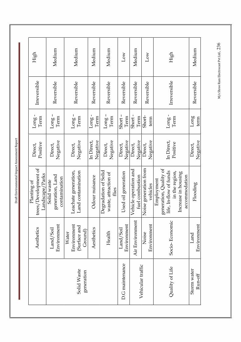
Dra
ft E
nv
iro
nm
en
tal
Imp
act
Ass
ess
me
nt
Re
po
rt
M/
s S
hre
e R
am
Ele
ctro
cast
Pv
t L
td.,
23
6
Aes
thet
ics
Pla
nti
ng
of
tree
s/D
evel
op
men
t o
f L
and
scap
e/P
ark
s
Dir
ect,
Po
siti
ve
Lo
ng
-T
erm
Irre
ver
sib
leH
igh
La
nd
/S
oil
En
vir
on
men
t
So
lid
was
te
gen
erat
ion
, Lan
d
con
tam
inat
ion
Dir
ect,
Neg
ativ
eL
on
g–
Ter
mR
ever
sib
leM
ediu
m
Wat
erE
nv
iro
nm
ent
(Su
rfac
e an
d
Gro
un
d)
Lea
chat
e g
ener
atio
n,
Lan
d c
on
tam
inat
ion
Dir
ect,
Neg
ativ
eL
on
g–
Ter
mR
ever
sib
leM
ediu
m
Aes
thet
ics
Od
ou
r n
uis
ance
InD
irec
t,N
egat
ive
Lo
ng
-T
erm
Rev
ersi
ble
Med
ium
So
lid
Wa
ste
gen
era
tio
n
Hea
lth
Deg
rad
atio
n o
f S
oli
d
was
te, a
ttra
ctio
n o
f fl
ies
Dir
ect,
Neg
ativ
eL
on
g–
Ter
mR
ever
sib
leM
ediu
m
D.G
mai
nte
nan
ceL
an
d/
So
ilE
nv
iro
nm
ent
Use
d o
il g
ener
ati
on
Dir
ect,
Neg
ativ
eS
ho
rt–
Ter
mR
ever
sib
leL
ow
Air
En
vir
on
men
tV
ehic
le o
per
ati
on
an
d
fuel
co
mb
ust
ion
Dir
ect,
Neg
ativ
eS
ho
rt-
Ter
mR
ever
sib
leM
ediu
mV
ehic
ula
r tr
affi
cN
ois
eE
nv
iro
nm
ent
No
ise
gen
erat
ion
fro
m
veh
icle
sD
irec
t,N
egat
ive
Sh
ort
-te
rmR
ever
sib
leL
ow
Qu
alit
y o
f L
ife
So
cio
-E
con
om
ic
Em
plo
ym
ent
gen
erat
ion
,Qu
alit
y o
f li
fe,I
n-f
low
of
fun
ds
in t
he
reg
ion
,In
crea
se i
n h
ou
sin
g
acc
om
mo
da
tio
n
InD
irec
t,P
osi
tiv
eL
on
g-
Ter
mIr
rev
ersi
ble
Hig
h
Sto
rm w
ater
Ru
n-o
ffL
and
En
vir
on
men
tF
loo
din
gD
irec
t,N
egat
ive
Lo
ng
term
Rev
ersi
ble
Med
ium

Draft Environmental Impact Assessment Report
M/s Shree Ram Electrocast Pvt Ltd., 237
CHAPTER-5.0 ENVIRONMENTAL MONITORING PLAN
Sl.No.
ParticularsMonitoringfrequency
Duration of monitoring
Importantparameters for
monitoring
I Air Quality
1 Ambient Air QualityMonitoring withinpremises
Once in amonth
Grab, 24 hrlysample
PM10, PM 2.5, SO2,NO2.
2 Stack/ChimneyMonitoring
Once in amonth
Grab Temperature,Velocity, SO2, PM,NOx, HC, CO
3 Fugitive emissionsmonitoring
Once in amonth
24 hourly PM 10 and PM 2.5
II Water Quality
1 Ground Water Analysis Once in amonth
Grab As per KSPCBrequirements
III Soil Quality
1 Soil quality analysis Pre monsoonand postmonsoon
Grab Colour, TexturalClass, pH, C,Infiltration rate,Moisture retentioncapacity, Organicmatter, Na,K,P,Pb,Cu,Zn,Cd,Fe
V Noise Quality
• MainGate/Boundary
• Power Plant
• D.G Set Room• Crushing Areas
• Vibrators
• Compressor• Loading and
Unloading
• Others as notices
Once in aMonth
24HrsMonitoring
Noise levels indB(A)
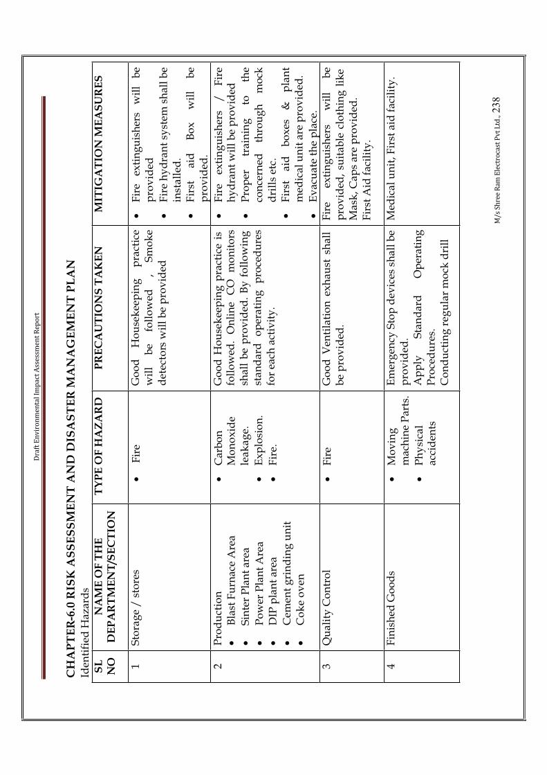
Dra
ft E
nv
iro
nm
en
tal
Imp
act
Ass
ess
me
nt
Re
po
rt
M/
s S
hre
e R
am
Ele
ctro
cast
Pv
t L
td.,
23
8
CH
AP
TE
R-6
.0 R
ISK
AS
SE
SS
ME
NT
AN
D D
ISA
ST
ER
MA
NA
GE
ME
NT
PL
AN
Iden
tifi
ed H
azar
ds
SL
NO
NA
ME
OF
TH
E
DE
PA
RT
ME
NT
/SE
CT
ION
TY
PE
OF
HA
ZA
RD
PR
EC
AU
TIO
NS
TA
KE
NM
ITIG
AT
ION
ME
AS
UR
ES
1S
tora
ge
/ s
tore
s•
Fir
eG
oo
d
Ho
use
kee
pin
g
pra
ctic
ew
ill
be
foll
ow
ed
, S
mo
ke
det
ecto
rs w
ill
be
pro
vid
ed
•F
ire
exti
ng
uis
her
s w
ill
be
pro
vid
ed
•F
ire
hy
dra
nt
syst
em s
hal
l b
e in
sta
lled
.•
Fir
st
aid
B
ox
w
ill
be
pro
vid
ed.
2P
rod
uct
ion
•B
last
Fu
rnac
e A
rea
•S
inte
r P
lan
t ar
ea
•P
ow
er P
lan
t A
rea
•D
IP p
lan
t ar
ea
•C
emen
t g
rin
din
g u
nit
•C
ok
e o
ven
•C
arb
on
Mo
no
xid
ele
ak
ag
e.
•E
xp
losi
on
.
•F
ire.
Go
od
Ho
use
kee
pin
g p
ract
ice
is
foll
ow
ed.
On
lin
e C
O
mo
nit
ors
shal
l b
e p
rov
ided
. B
y f
oll
ow
ing
st
and
ard
o
per
atin
g
pro
ced
ure
sfo
r ea
ch a
ctiv
ity
.
•F
ire
exti
ng
uis
her
s /
F
ire
hy
dra
nt
wil
l b
e p
rov
ided
•P
rop
er
trai
nin
g
to
the
con
cern
ed
thro
ug
h
mo
ckd
rill
s et
c.
•F
irst
ai
d
bo
xes
&
p
lan
tm
edic
al u
nit
are
pro
vid
ed.
•E
vac
uat
e th
e p
lace
.3
Qu
alit
y C
on
tro
l•
Fir
eG
oo
d V
enti
lati
on
ex
hau
st s
hal
l b
e p
rov
ided
.F
ire
exti
ng
uis
her
s w
ill
be
pro
vid
ed,
suit
able
clo
thin
g l
ike
Mas
k, C
aps
are
pro
vid
ed.
Fir
st A
id f
acil
ity
.
4F
inis
hed
Go
od
s•
Mo
vin
gm
ach
ine
Par
ts.
•P
hy
sica
lac
cid
ents
Em
erg
ency
Sto
p d
evic
es s
hal
l b
e p
rov
ided
.A
pp
ly
Sta
nd
ard
O
per
atin
gP
roce
du
res.
Co
nd
uct
ing
reg
ula
r m
ock
dri
ll
Med
ical
un
it, F
irst
aid
fac
ilit
y.

Dra
ft E
nv
iro
nm
en
tal
Imp
act
Ass
ess
me
nt
Re
po
rt
M/
s S
hre
e R
am
Ele
ctro
cast
Pv
t L
td.,
23
9
Iden
tifi
ed O
ccu
pat
ion
al H
eal
th H
azar
ds
Ty
pe
of
Ha
za
rdA
reas
Pre
ven
tiv
e /
Mit
igati
on
measu
res
Du
stR
aw m
ater
ial
han
dli
ng
&
sto
rag
e y
ard
Wil
l b
e tr
ansp
ort
ed i
n t
he
tru
cks
wit
h t
arp
ual
in c
ov
ers.
En
vis
aged
to
in
stal
l a
tru
ck t
iple
r. W
ater
sp
rin
kle
rs i
n t
he
yar
d.
Co
ver
ed c
on
vey
or
bel
ts f
or
RM
fe
edin
g
to
RM
HS
b
un
ker
s as
wel
l to
B
F.
Pn
eum
atic
co
nv
eyo
r fo
r d
ust
han
dli
ng
fr
om
D
ry
GC
P
to
Sin
ter.
P
rov
idin
g
per
son
nel
p
rote
ctiv
eeq
uip
men
ts
lik
e re
spir
ato
rs,
cap
s,
apro
ns.
D
evel
op
men
t o
f g
reen
ary
al
lar
ou
nd
th
e y
ard
. Dev
elo
pin
g R
oad
s, a
shp
hal
tin
g e
tc.
No
ise
Blo
wer
ho
use
,
ID
fan
h
ou
se,
Tu
rbin
e h
all,
A
irco
mp
ress
or
ho
use
, DG
&P
um
p h
ou
ses.
Sel
ecti
on
o
f eq
uip
men
ts
con
firm
ing
to
st
and
ard
s.
i.e.
<
90
dB
A
at
1 m
trd
ista
nce
. A
ll t
hes
e ar
eas
shal
l b
e u
nm
ann
ed d
ue
to h
igh
lev
el a
uto
mat
ion
. S
uit
able
Ear
mu
ffs
wil
l p
rov
ided
to
th
e w
ork
ers
du
rin
g i
nsp
ecti
on
s.G
reen
bel
t co
rrid
or
wil
l b
e d
evel
op
ed a
lon
g t
he
per
iph
ery
of
the
pla
nt.
Ex
trem
e H
eat
Cas
t h
ou
se,
Pig
C
asti
ng
Mac
hin
e,
Sin
teri
ng
pla
tfo
rm, S
team
pip
ing
Pro
vid
ing
pro
per
PP
E l
ike
leg
gau
rds
wit
h s
ho
es,
Fac
e sh
eild
, le
ath
er h
and
g
lou
se,
Lea
ther
A
pro
ns,
h
elm
ets
etc.
T
her
mal
in
sula
tio
n
for
stea
m
lin
e.P
rov
idin
g f
ans,
per
son
nel
co
oli
ng
dev
ices
, wat
er s
ho
wer
s et
c.B
F G
as -
CO
BF
To
p,
Sto
ve,
GC
P,
Cas
t h
ou
se,
Sin
ter
pla
t fo
rm,
Bo
iler
.
On
lin
e g
as d
ete
cto
r sy
stem
s sh
all
be
inst
alle
d i
n a
dd
itio
n t
o p
ort
able
CO
mo
nit
ors
. O2 m
ask
s &
kit
s sh
all
be
pro
vid
ed.
No
ise
Blo
wer
ho
use
,
ID
fan
h
ou
se,
Tu
rbin
e h
all,
A
irco
mp
ress
or
ho
use
, DG
&P
um
p h
ou
ses.
Sel
ecti
on
o
f eq
uip
men
ts
con
firm
ing
to
st
and
ard
s.
i.e.
<
90
dB
A
at
1 m
trd
ista
nce
. A
ll t
hes
e ar
eas
shal
l b
e u
nm
ann
ed d
ue
to h
igh
lev
el a
uto
mat
ion
. S
uit
able
Ear
mu
ffs
wil
l p
rov
ided
to
th
e w
ork
ers
du
rin
g i
nsp
ecti
on
s.G
reen
bel
t co
rrid
or
wil
l b
e d
evel
op
ed a
lon
g t
he
per
iph
ery
of
the
pla
nt.
Pre
lim
inar
y H
azar
d A
nal
ysi
s fo
r P
roce
ss a
nd
Sto
rag
e A
reas
Eq
uip
me
nt
Pro
cess
Po
ten
tial
Haz
ard
Pro
vis
ion

Dra
ft E
nv
iro
nm
en
tal
Imp
act
Ass
ess
me
nt
Re
po
rt
M/
s S
hre
e R
am
Ele
ctro
cast
Pv
t L
td.,
24
0
BF
Red
uct
ion
of
Iro
n O
reE
xp
losi
on
, Gas
lea
kag
e –
air
po
llu
tio
nG
as l
eak
age
det
ecti
on
sy
stem
, Str
ict
foll
ow
up
of
Std
Op
erat
ing
Pra
ctic
es
Blo
wer
Ho
use
Gen
erat
ion
of
bla
stN
ois
eP
rop
er s
elec
tio
n o
f m
ach
iner
y.
Rem
ote
co
ntr
oll
ed.
Sto
ve
sP
re h
eati
ng
of
bla
stG
as l
eak
age,
Fir
e &
Ex
plo
sio
nS
afet
y i
nte
r-lo
ckin
g, g
as d
etec
tors
.
RM
HS
Raw
mat
eria
l h
and
lin
g
& t
ran
spo
rtat
ion
Du
stC
lose
d s
yst
em, d
ust
ex
trac
tio
n s
yst
em
/ d
ry f
og
du
st s
up
pre
ssio
n s
yst
em.
GC
P–
Dry
ty
pe
Cle
anin
g o
f B
F g
asD
ust
& G
as l
eak
age
Pn
eum
atic
co
nv
eyo
r, G
as d
etec
tor
syst
em
Pu
mp
Ho
use
Wat
er p
um
pin
gN
ois
eR
emo
te c
on
tro
l sy
stem
. Pro
per
se
lect
ion
of
m/
c.
Co
mp
ress
or
Ho
use
Gen
erat
ion
of
com
pre
ssed
air
.U
sag
e o
f co
mp
ress
ed a
ir f
or
hu
man
bo
dy
cle
anin
gC
reat
ion
of
awar
enes
s &
tra
inin
g.
Pig
cast
ing
mach
ine
Pig
gin
gH
igh
am
bie
nt
tem
per
atu
re,
Sp
urt
ing
of
HM
.
Iso
lati
on
, bar
rica
din
g, e
ng
g c
on
tro
ls.
Std
op
erat
ing
pra
ctic
es.
Sin
ter
Pla
nt
Cru
shin
g &
Sin
teri
ng
Ex
cess
hea
tIs
ola
tio
n &
un
man
ned
op
erat
ion
Du
ctil
e i
ron
pip
e p
lan
tH
igh
am
bie
nt
tem
per
atu
reIs
ola
tio
n, b
arri
cad
ing
, en
gg
co
ntr
ols
. S
td o
per
atin
g p
ract
ices
.
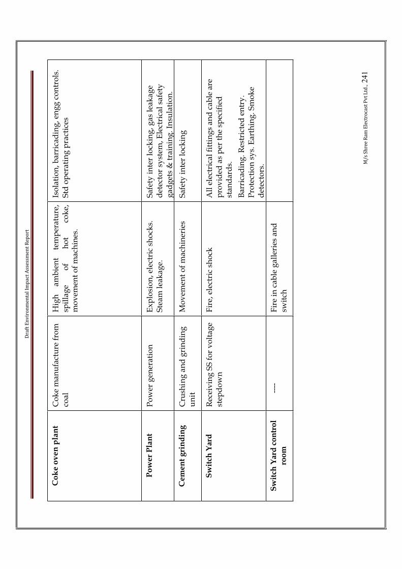
Dra
ft E
nv
iro
nm
en
tal
Imp
act
Ass
ess
me
nt
Re
po
rt
M/
s S
hre
e R
am
Ele
ctro
cast
Pv
t L
td.,
24
1
Co
ke
ov
en
pla
nt
Co
ke
man
ufa
ctu
re f
rom
co
al
Hig
h
amb
ien
t te
mp
erat
ure
,sp
illa
ge
of
ho
t co
ke,
mo
vem
ent
of
mac
hin
es.
Iso
lati
on
, bar
rica
din
g, e
ng
g c
on
tro
ls.
Std
op
erat
ing
pra
ctic
es
Po
we
r P
lan
tP
ow
er g
ener
atio
nE
xp
losi
on
, ele
ctri
c sh
ock
s.
Ste
am l
eak
age.
Saf
ety
in
ter
lock
ing
, gas
lea
kag
e d
etec
tor
syst
em, E
lect
rica
l sa
fety
g
adg
ets
& t
rain
ing
. In
sula
tio
n.
Ce
me
nt
gri
nd
ing
Cru
shin
g a
nd
gri
nd
ing
u
nit
Mo
vem
ent
of
mac
hin
erie
s S
afet
y i
nte
r lo
ckin
g
Sw
itch
Yard
Rec
eiv
ing
SS
fo
r v
olt
age
step
do
wn
Fir
e, e
lect
ric
sho
ckA
ll e
lect
rica
l fi
ttin
gs
and
cab
le a
re
pro
vid
ed a
s p
er t
he
spec
ifie
d
stan
dar
ds.
Bar
rica
din
g. R
estr
icte
d e
ntr
y.
Pro
tect
ion
sys.
Ear
thin
g. S
mo
ke
det
ecto
rs.
Sw
itch
Yar
d c
on
tro
l
roo
m--
--F
ire
in c
able
gal
leri
es a
nd
sw
itch

Draft Environmental Impact Assessment Report
M/s Shree Ram Electrocast Pvt Ltd., 242
CHAPTER-7.0 PROJECT BENEFITS
The benefits from the project, listed as follows:
• Increase in direct and indirect employment opportunities• Zero discharge of water
• The proposed green belt development program will increase biomass andbiodiversity and leads to sustainable environment
• The proposed green belt will not give opportunities for suitable habitat toanimals but also attracts avifauna
• The existing infrastructure will be utilized as far as possible, and thereforedisturbance ecosystem balance is negligible due to infrastructure facilities
• The industry spend money for their social activities for the benefit of the nearly living people with in 10 km radius
• CSR activities proposedCSR Activities conducted and proposed around factory premises
Programme Conducted Proposed Time frame
Health Conducted medicalcamp at Honnarahalli Village
Construction of ladies toilet inKudadarahal Village
Before April 2013
Free medical checkup camp atKudadarahal and Hatchollivillages
Twice in a month. Started from
Jan,2012
Up gradation of toilets and washrooms in the Govt Schools
December 2013
Education Distribution of notebooks to schoolchildren (each child 7 note books) ofKudadarahal villages
• Higher educationprogramme: Sponsership to meritorious and underprevillaged students forDiploma Courses at theprivate & Govt.polytechnics.
• Opportunity foremployment uponcompletion of course
Started from academic year
2011.
Workshop wasconducted to farmerson scientific irrigation, soil management and economic feasibility of crops by agriculturalscientists

Draft Environmental Impact Assessment Report
M/s Shree Ram Electrocast Pvt Ltd., 243
Welfare Electrification:Distribution ofstreetlights toKudadadarahal,Sridharagadda andNagalapura Villages
Training on vocational courses intailoring, candle making, bookbinding, etc., for economicupliftment of poor woman.
During financial year 2012
Provided temporaryshelters and food toflood affectedpopulation ofHonnarahalli,chikballary,shridharagaddavillages (about 65families still dwellingin our premises)
Distribution of tricycle tophysically handicapped persons in Kudadarahal and HatcholliVillages.
Before December 2012
Upgradation of MDR road fromSiruguppa junction to Hatcholliwith state PWD under PPP scheme
On or before 2015
Concreting of village internal roads in Kududarahal, Honnarahalli and Hatchcholli grampanchayaths
On or before 2015
Shelter to traffic police Jan- Feb 2012
Traffic signage/ control boards Jan- Feb 2012Providing safe drinking water,scientifically.
During financial year 2012
Infrastructural welfare
Distribution of saplings topanchayaths & schools.
Before March 2012
Sports Distribution of sports kits and materials toschools atKudadarahal Village
Conduct of Inter School Athleticmeet with sports materials.
September 2012
The budget for CSR activities will be 5% of the project cost to be spent over 5 years period.

Draft Environmental Impact Assessment Report
M/s Shree Ram Electrocast Pvt Ltd., 244
CHAPTER-8.0 ENVIRONMENTAL MANAGEMENT PLAN
M/s Shree Ram electrocast Pvt Limited will develop the following managementactivities for the Environmental Management Programme which will meet all statutory requirements and help to improve environmental quality.In order to improve the aesthetic look of the area and enhance the land use as well as to compensate for any loss in ecology during construction, adequate plantationprogrammes around the project site have been planned and will be adopted.Development of green belt will include plantation of trees along boundary of the factory, roads, raw material yard and other available spaces. Over 35% of total area of factory will be covered under green cover.A detailed monitoring for different environmental parameters will be carried out as per direction of Karnataka State Pollution Control Board. An environmental management group would be established to implement themanagement plan.
AIR ENVIRONMENT
The mitigation measures needs to be adopted during the operation stage to control the negative impacts on air environment surrounding the project area are given below:
• Gas cleaning plant for BF gas is provided to supply clean gas to consuming units. Viz BF stoves , power plant boiler and sinter pant
• Annealing furnace, MG treatment and zinc coating unit will be provided with stacks as stipulated by KSPCB norms.
• Magnesium converters and zinc coating units will be provided with Bag filters.
• Sinter plant will be connected to ESP to minimize the impact of air pollution.• AFBC boiler will also be connected to ESP.
• Reducing VOC emissions from sinter plant by process optimization, including minimizing stoppages and maintaining consistent operation in terms of strand speed, bed composition (particularly consistent blending of reverts whichshould not contain oil), bed height, use of additions such as burnt lime; and keeping the strand, ductwork, ESP and bag filter air tight
• Pollution reduction from coke making relies as much on techniques andoperation.
• By stamp charging the emission during charging can be minimized.• Water spraying will be adopted at loading and unloading points and storage
yards which will reduce fugitive emissions due to movement of truck.
• All the internal roads will be asphalted to reduce the fugitive dust due to truck movement.
• Green belt cover will be provided. For this, the project has proposed to have green belt cover to an extent 35% of total area of the land has been demarcated as Green Belt. Already 12000 plants have been planted maintaining the good Flora & Fauna. Further, we are planned to plant around 5000 plants during the
Draft Environmental Impact Assessment Report
M/s Shree Ram Electrocast Pvt Ltd., 245
financial year 2011-2012. Further 15,000 trees are proposed to be planted as a part of greenbelt development.
CONTROL OF FUGITIVE EMISSIONS AT VARIOUS AUXILIARY FACILITIESINSIDE THE PLANT
CONTROL OF PRIMARY AND SECONDARY EMISSIONS FROM SINTER PLANT
The source of dust emissions will be at the transfer points of the raw materials, which will be contained by the installation of Agglomerative Dust Suppression (ADS) system.The emissions from the sintering process, where combustion take place, will be routedthrough Electrostatic Precipitator, ultimately to be released into the atmosphere through stack.
CONTROL OF FUGITIVE EMISSIONS AT VARIOUS AUXILIARY FACILITIESINSIDE THE PLANT
There will be Dust Suppression Systems/ Foggy Dust Arresters to control fugitiveemissions at various facilities inside the plant
WATER POLLUTIONThe plant will be designed as a zero discharge plant as far as the process effluents are concerned. The water will be recirculated through required cooling and treatment. In cases were contamination will take place during cooling, a treatment plant will beinstalled inside the plant. After treatment, the supernatant water will be sent back to the plant. No plant effluent will be discharged outside the plant premises.
• There is no effluent water in this process• Use of high pressure hoses for area cleaning
• House maintenance and floor wash wastewater will be reused after treatment.
• No wastewater will be discharged to any ground water or to the surface water body.
• Storm water drains will be provided to avoid flooding in the proposed project site area and provision will be made for runoff get diverted to recharge pits with pre oil and grease trap there by increasing the groundwater table.
• No water will be drawn during lean season. Excess water will be drawn and stored during rainy season and that will be used during lean season.
NOISE ENVIRONMENT
• Proper mounting of equipments and providing noise insulating enclosures or paddling where practicable.
• The equipments will be maintained at all times to ensure permissible noiselevels.
• Appropriate advanced silencers, acoustic barriers; vibration-reducing pads will be provided for all noise generating equipments.
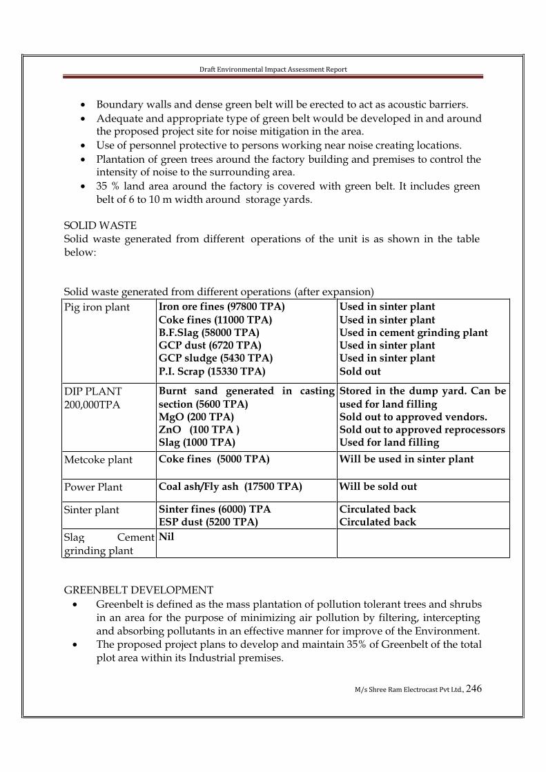
Draft Environmental Impact Assessment Report
M/s Shree Ram Electrocast Pvt Ltd., 246
• Boundary walls and dense green belt will be erected to act as acoustic barriers.
• Adequate and appropriate type of green belt would be developed in and around the proposed project site for noise mitigation in the area.
• Use of personnel protective to persons working near noise creating locations.
• Plantation of green trees around the factory building and premises to control the intensity of noise to the surrounding area.
• 35 % land area around the factory is covered with green belt. It includes green belt of 6 to 10 m width around storage yards.
SOLID WASTE Solid waste generated from different operations of the unit is as shown in the table below:
Solid waste generated from different operations (after expansion)
Pig iron plant Iron ore fines (97800 TPA)
Coke fines (11000 TPA) B.F.Slag (58000 TPA) GCP dust (6720 TPA) GCP sludge (5430 TPA)
P.I. Scrap (15330 TPA)
Used in sinter plant
Used in sinter plant Used in cement grinding plant Used in sinter plant Used in sinter plant
Sold out
DIP PLANT200,000TPA
Burnt sand generated in casting
section (5600 TPA)MgO (200 TPA)ZnO (100 TPA )Slag (1000 TPA)
Stored in the dump yard. Can be
used for land fillingSold out to approved vendors. Sold out to approved reprocessorsUsed for land filling
Metcoke plant Coke fines (5000 TPA) Will be used in sinter plant
Power Plant Coal ash/Fly ash (17500 TPA) Will be sold out
Sinter plant Sinter fines (6000) TPA ESP dust (5200 TPA)
Circulated backCirculated back
Slag Cementgrinding plant
Nil
GREENBELT DEVELOPMENT
• Greenbelt is defined as the mass plantation of pollution tolerant trees and shrubs in an area for the purpose of minimizing air pollution by filtering, intercepting and absorbing pollutants in an effective manner for improve of the Environment.
• The proposed project plans to develop and maintain 35% of Greenbelt of the totalplot area within its Industrial premises.

Draft Environmental Impact Assessment Report
M/s Shree Ram Electrocast Pvt Ltd., 247
STORM WATER MANAGEMENT
• Storm water drains will be provided within the premises of the industry to avoid mixing with affluent.
• Storm water drains will be provided on both sides of the roads. Rectangular drains will be provided based on the quantity of storm water to be conveyed and depth limitations.
• 40 recharge pits are provided for the purpose of ground water recharge.
ECOLOGICAL ASPECTS• Continuing greening efforts in and around the project site.
• Conservation of existing vegetation and afforestation covering larger areas near and around existing project area.
AESTHETICS ASPECTS
• The entire area will be planted with local tree species of aesthetic value, fodder value, fruit bearing and birds attracting tree species. Hence it would beconverted into a possible park for the nearby villages and project staff forrecreation.
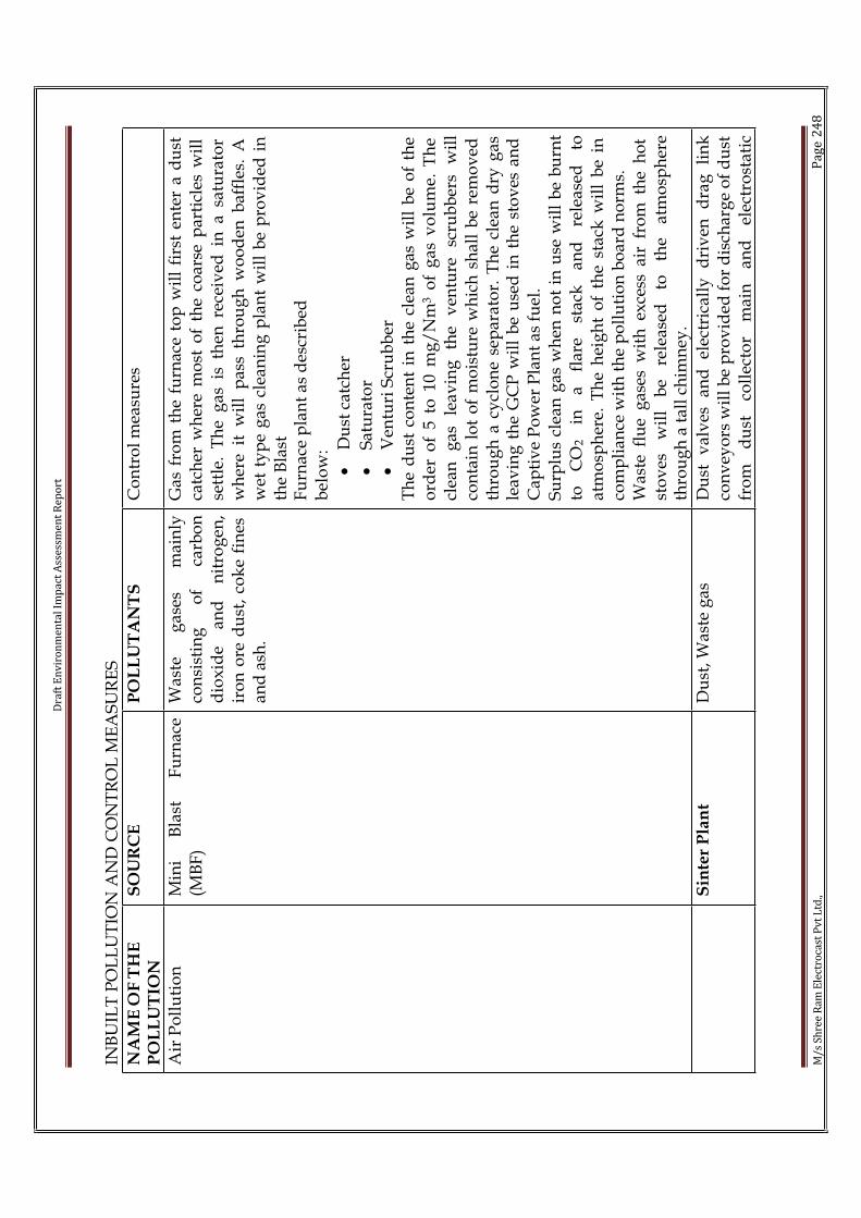
Dra
ft E
nv
iro
nm
en
tal
Imp
act
Ass
ess
me
nt
Re
po
rt
M/
s S
hre
e R
am
Ele
ctro
cast
Pv
t L
td.,
Pa
ge
24
8
INB
UIL
T P
OL
LU
TIO
N A
ND
CO
NT
RO
L M
EA
SU
RE
S
NA
ME
OF
TH
EP
OL
LU
TIO
NS
OU
RC
EP
OL
LU
TA
NT
SC
on
tro
l m
easu
res
Air
Po
llu
tio
nM
ini
Bla
st
Fu
rnac
e(M
BF
)W
aste
g
ases
m
ain
lyco
nsi
stin
g
of
carb
on
dio
xid
e an
d
nit
rog
en,
iro
n o
re d
ust
, co
ke
fin
es
and
ash
.
Gas
fro
m t
he
furn
ace
top
wil
l fi
rst
ente
r a
du
st
catc
her
wh
ere
mo
st o
f th
e co
arse
par
ticl
es w
ill
sett
le.
Th
e g
as i
s th
en r
ecei
ved
in
a s
atu
rato
r w
her
e it
wil
l p
ass
thro
ug
h w
oo
den
baf
fles
. A
w
et t
yp
e g
as c
lean
ing
pla
nt
wil
l b
e p
rov
ided
in
th
e B
last
Fu
rnac
e p
lan
t as
des
crib
edb
elo
w:
•D
ust
cat
cher
•S
atu
rato
r•
Ven
turi
Scr
ub
ber
Th
e d
ust
co
nte
nt
in t
he
clea
n g
as w
ill
be
of
the
ord
er o
f 5
to 1
0 m
g/
Nm
3 o
f g
as
vo
lum
e. T
he
clea
n
gas
le
avin
g
the
ven
ture
sc
rub
ber
s w
ill
con
tain
lo
t o
f m
ois
ture
wh
ich
sh
all
be
rem
ov
ed
thro
ug
h a
cy
clo
ne
sep
arat
or.
Th
e cl
ean
dry
gas
le
avin
g t
he
GC
P w
ill
be
use
d i
n t
he
sto
ves
an
d
Cap
tiv
e P
ow
er P
lan
t as
fu
el.
Su
rplu
s cl
ean
gas
wh
en n
ot
in u
se w
ill
be
bu
rnt
to
CO
2
in
a fl
are
stac
k
and
re
leas
ed
toat
mo
sph
ere.
Th
e h
eig
ht
of
the
stac
k w
ill
be
in
com
pli
ance
wit
h t
he
po
llu
tio
n b
oar
d n
orm
s.W
aste
flu
e g
ases
wit
h e
xce
ss a
ir f
rom
th
e h
ot
sto
ves
w
ill
be
rele
ased
to
th
e at
mo
sph
ere
thro
ug
h a
tal
l ch
imn
ey.
Sin
ter
Pla
nt
Du
st, W
aste
gas
Du
st
val
ves
an
d
elec
tric
ally
d
riv
en
dra
g
lin
kco
nv
eyo
rs w
ill
be
pro
vid
ed f
or
dis
char
ge
of
du
st
fro
m
du
st
coll
ecto
r m
ain
an
d
elec
tro
stat
ic

Dra
ft E
nv
iro
nm
en
tal
Imp
act
Ass
ess
me
nt
Re
po
rt
M/
s S
hre
e R
am
Ele
ctro
cast
Pv
t L
td.,
Pa
ge
24
9
pre
cip
itat
or
wil
l b
e en
vis
aged
fo
r d
edu
stin
g o
f w
aste
gas
ses.
Aft
er t
reat
men
t g
as s
hal
l co
nta
in
less
th
an 1
00 m
g/
NM
3 o
f p
arti
cles
. Th
e co
llec
ted
d
ust
wil
l b
e re
cycl
ed.
Ca
pti
ve
Po
we
r P
lan
tF
ly
ash
, F
ug
itiv
eem
issi
on
, SP
M, S
O2
Hig
h E
ffic
ien
cy E
lect
ro-S
tati
c P
reci
pit
ato
rs,
De
-d
ust
ing
sy
stem
s w
ith
wat
er s
pra
yin
g a
nd
Sta
ck
1.
Po
we
r p
lan
tB
ott
om
ash
& f
ly a
shW
ill
be
sold
ou
tS
oli
d W
ast
e
2.
MB
FS
lag
It w
ill
be
uti
lise
das
raw
mat
eria
l fo
r th
e ce
men
t p
lan
t.H
az
ard
ou
s w
ast
e1
. M
ach
ine
rie
s2
. Ge
ar
bo
xe
s
3.
Co
mp
ress
ors
4.D
.G.s
ets
Use
d o
ils
Th
ey w
ill
be
coll
ecte
d i
n d
rum
s a
nd
wel
l-p
ack
edd
rum
s w
ill
be
tem
po
rari
ly s
tore
d i
n s
pec
ific
ally
m
ark
ed a
rea.
No
ise
Po
llu
tio
nF
rom
all
th
e u
nit
sT
he
maj
or
equ
ipm
ent
of
hig
h
no
ise
can
b
eid
enti
fied
as
b
last
fa
ns,
ID a
nd
FD
fan
s tu
rbin
e a
nd
air
co
mp
ress
or
Lo
w n
ois
e d
esig
n a
nd
su
ita
ble
en
clo
sure
s w
ill
ensu
re t
ha
t th
e no
ise
lev
els
are
res
tric
ted
wel
l w
ith
in
the
stip
ula
tio
ns
of
the
PC
B’s
n
orm
s(b
elo
w
80
dB
(A)
at
1 m
).
Th
e m
easu
res
wil
lin
clu
de
the
red
uct
ion
o
f n
ois
e at
so
urc
ep
rov
idin
g a
cou
stic
en
clo
sure
s fo
r th
e eq
uip
men
t an
d i
sola
tin
g t
he
no
ise
pro
du
cin
g e
qu
ipm
ent
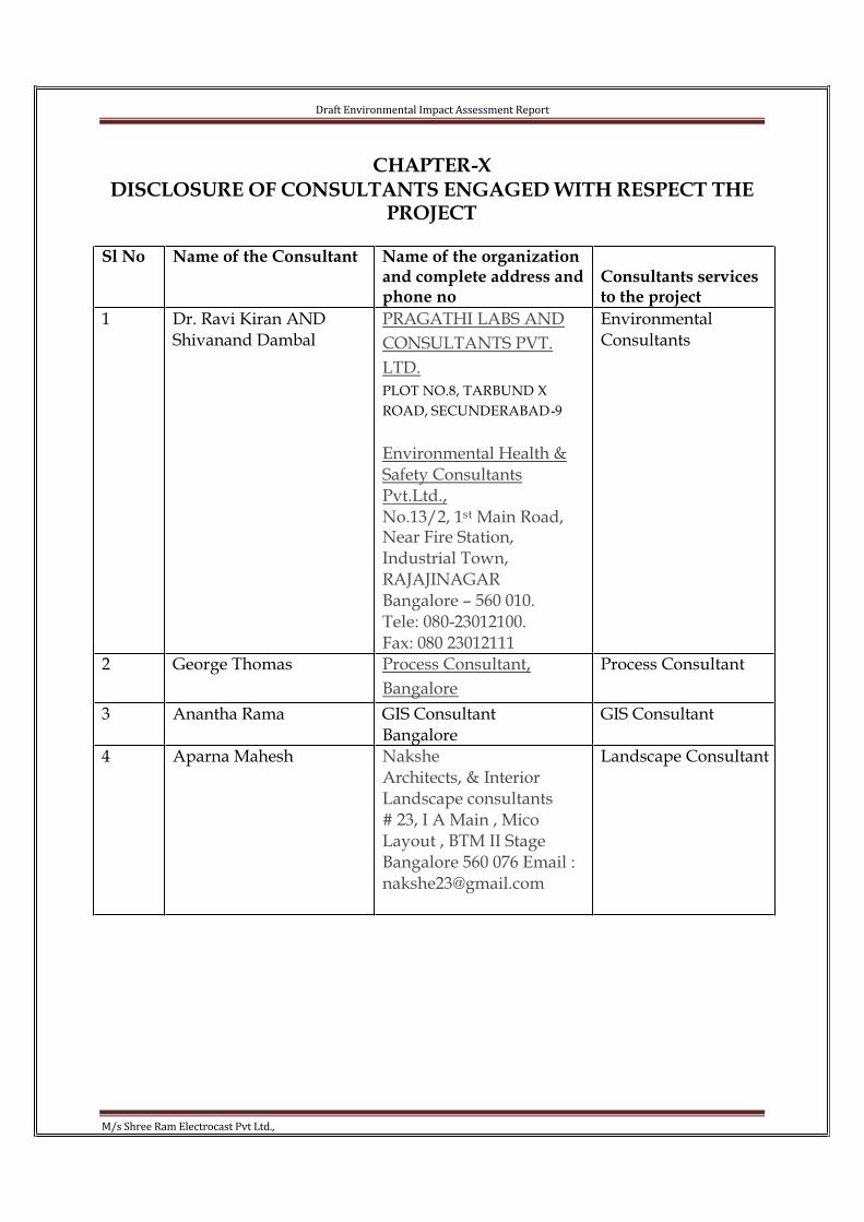
Draft Environmental Impact Assessment Report
M/s Shree Ram Electrocast Pvt Ltd.,
CHAPTER-XDISCLOSURE OF CONSULTANTS ENGAGED WITH RESPECT THE
PROJECT
Sl No Name of the Consultant Name of the organization and complete address and phone no
Consultants services to the project
1 Dr. Ravi Kiran ANDShivanand Dambal
PRAGATHI LABS AND
CONSULTANTS PVT.
LTD.
PLOT NO.8, TARBUND X
ROAD, SECUNDERABAD-9
Environmental Health & Safety Consultants Pvt.Ltd.,No.13/2, 1st Main Road,Near Fire Station, Industrial Town,RAJAJINAGARBangalore – 560 010.Tele: 080-23012100.Fax: 080 23012111
EnvironmentalConsultants
2 George Thomas Process Consultant,
Bangalore
Process Consultant
3 Anantha Rama GIS ConsultantBangalore
GIS Consultant
4 Aparna Mahesh NaksheArchitects, & Interior Landscape consultants# 23, I A Main , Mico Layout , BTM II StageBangalore 560 076 Email : [email protected]
Landscape Consultant