draft etsi es 201 168 v1.2 · draft etsi es 201 168 v1.2.1 (2000-07) etsi standard speech...
TRANSCRIPT
Draft ETSI ES 201 168 V1.2.1 (2000-07)ETSI Standard
Speech processing, Transmission and Quality Aspects (STQ);Transmission characteristics of digital
Private Branch eXchanges (PBXs) for interconnectionto private networks, to the public switched network
or to IP gateways
ETSI
Draft ETSI ES 201 168 V1.2.1 (2000-07)2
ReferenceRES/STQ-00012
KeywordsPABX, transmission, digital, IP
ETSI
650 Route des LuciolesF-06921 Sophia Antipolis Cedex - FRANCE
Tel.: +33 4 92 94 42 00 Fax: +33 4 93 65 47 16
Siret N° 348 623 562 00017 - NAF 742 CAssociation à but non lucratif enregistrée à laSous-Préfecture de Grasse (06) N° 7803/88
Important notice
Individual copies of the present document can be downloaded from:http://www.etsi.org
The present document may be made available in more than one electronic version or in print. In any case of existing orperceived difference in contents between such versions, the reference version is the Portable Document Format (PDF).
In case of dispute, the reference shall be the printing on ETSI printers of the PDF version kept on a specific networkdrive within ETSI Secretariat.
Users of the present document should be aware that the document may be subject to revision or change of status.Information on the current status of this and other ETSI documents is available at http://www.etsi.org/tb/status/
If you find errors in the present document, send your comment to:[email protected]
Copyright Notification
No part may be reproduced except as authorized by written permission.The copyright and the foregoing restriction extend to reproduction in all media.
© European Telecommunications Standards Institute 2000.All rights reserved.
ETSI
Draft ETSI ES 201 168 V1.2.1 (2000-07)3
Contents
Intellectual Property Rights................................................................................................................................8
Foreword ............................................................................................................................................................8
1 Scope ........................................................................................................................................................9
2 References ................................................................................................................................................9
3 Definitions and abbreviations ................................................................................................................113.1 Definitions ........................................................................................................................................................113.1.1 Private Branch eXchange (PBX) ................................................................................................................113.1.2 Test points, PBX input and output and half connections ............................................................................113.1.2.1 Test points.............................................................................................................................................113.1.2.2 PBX input and output............................................................................................................................123.1.2.3 Half connections (analogue 2-wire or 4-wire, or digital) ......................................................................123.1.3 Relative levels.............................................................................................................................................123.1.3.1 Test points.............................................................................................................................................123.1.3.2 Analogue interfaces...............................................................................................................................123.1.4 Transmission loss........................................................................................................................................123.1.4.1 Nominal transmission loss, analogue half connections .........................................................................123.1.4.2 Switching Loss (SL)..............................................................................................................................123.1.4.3 Nominal transmission loss, full connections .........................................................................................133.1.5 Loss distortion with frequency....................................................................................................................173.1.6 Parameters relevant for echo and stability ..................................................................................................173.1.6.1 Terminal Balance Return Loss (TBRL) ................................................................................................173.1.6.2 Stability loss ..........................................................................................................................................173.1.6.3 Echo Loss (EL) and weighted Terminal Coupling Loss (TCLw)..........................................................173.1.7 Digital parameters.......................................................................................................................................183.1.7.1 Bit integrity ...........................................................................................................................................183.1.8 Characteristics of interfaces ........................................................................................................................183.1.8.1 2-wire analogue interface ......................................................................................................................183.1.8.1.1 Interface L2 .....................................................................................................................................183.1.8.1.2 Interface M2 ....................................................................................................................................183.1.8.1.3 Interface K2.....................................................................................................................................193.1.8.2 4-wire analogue interfaces.....................................................................................................................193.1.8.2.1 Interface M4 ....................................................................................................................................193.1.8.3 Digital interfaces ...................................................................................................................................193.1.8.3.1 Interface LD.....................................................................................................................................193.1.8.3.2 Interface MD ...................................................................................................................................193.1.8.3.3 Interface KD ....................................................................................................................................193.1.8.4 System specific (non-analogue) interfaces ............................................................................................193.1.8.4.1 Interface MS ....................................................................................................................................193.1.9 Voice band parameters of a connection between two interfaces of the same PBX.....................................193.1.9.1 General ..................................................................................................................................................193.1.9.2 Overall transmission parameters ...........................................................................................................203.1.9.2.1 Transmission loss ............................................................................................................................203.1.9.2.2 Other overall parameters .................................................................................................................203.1.9.3 Delay .....................................................................................................................................................203.1.9.3.1 Mean one way transmission time.....................................................................................................203.1.9.3.2 Group delay .....................................................................................................................................203.1.9.3.3 Group delay distortion.....................................................................................................................203.1.10 Loudness Ratings (LR) ...............................................................................................................................203.1.10.1 Receive Loudness Rating (RLR)...........................................................................................................203.1.10.2 Send Loudness Rating (SLR) ................................................................................................................203.1.10.3 Talker sidetone, SideTone Masking Rating (STMR)............................................................................203.1.10.4 Listener SideTone Rating (LSTR) ........................................................................................................203.1.10.5 Talker Echo Loudness Rating (TELR)..................................................................................................213.1.10.6 Noise rejection capability......................................................................................................................21
ETSI
Draft ETSI ES 201 168 V1.2.1 (2000-07)4
3.1.11 System specific telephony terminal (wired or cordless)..............................................................................213.1.12 Ear Reference Point (ERP) .........................................................................................................................213.1.13 Mouth Reference Point (MRP) ...................................................................................................................213.1.14 Acoustic Reference Level (ARL)................................................................................................................213.1.15 dBPa ...........................................................................................................................................................213.1.16 dBPa(A)......................................................................................................................................................213.2 Abbreviations ...................................................................................................................................................23
4 Compliance principles............................................................................................................................24
5 Characteristics of analogue interfaces ...................................................................................................245.1 PBX input impedance of interfaces K2, L2, M2 and M4 .................................................................................245.2 Transmission loss .............................................................................................................................................255.2.1 Nominal transmission loss ..........................................................................................................................255.2.2 Variation of gain with input level ...............................................................................................................255.2.3 Loss distortion with frequency....................................................................................................................265.3 Group delay distortion......................................................................................................................................275.4 Noise ................................................................................................................................................................275.4.1 Weighted noise of interfaces without a feeding bridge ...............................................................................275.4.2 Weighted noise of interfaces with a feeding bridge ....................................................................................285.4.2.1 Output connection .................................................................................................................................285.4.2.2 Input connection....................................................................................................................................295.4.3 Single frequency noise of interfaces K2, L2, M2 and M4 ..........................................................................295.5 Crosstalk...........................................................................................................................................................305.6 Total distortion including quantizing distortion ...............................................................................................305.6.1 Values of total distortion of interfaces without a feeding bridge ................................................................305.6.2 Values of total distortion of interfaces with a feeding bridge .....................................................................315.7 Discrimination against out-of-band signals applied to the K2, L2, M2 and M4 input interfaces .....................335.7.1 Input signals above 4,6 kHz........................................................................................................................335.8 Echo and stability of interfaces K2, L2 and M2 ...............................................................................................335.8.1 Terminal Balance Return Loss (TBRL)......................................................................................................335.8.2 Stability loss................................................................................................................................................34
6 Characteristics of digital interfaces........................................................................................................346.1 Coding law .......................................................................................................................................................346.2 Transmission loss .............................................................................................................................................356.3 Bit sequence independence...............................................................................................................................35
7 Characteristics of system specific (non-analogue) MS interfaces .........................................................357.1 Equipment Impairment Factor, Ie.....................................................................................................................357.2 Transmission loss .............................................................................................................................................35
8 System specific telephones (wired or cordless) .....................................................................................368.1 General .............................................................................................................................................................368.1.1 Applicability of transmission characteristics ..............................................................................................368.1.2 Volume control ...........................................................................................................................................368.2 Speech performance characteristics for 3,1 kHz handset telephones (wired or cordless).................................368.2.1 Sensitivity - frequency response .................................................................................................................368.2.1.1 Send Sensitivity.....................................................................................................................................368.2.1.2 Receive Sensitivity................................................................................................................................378.2.2 Send and Receive Loudness Ratings (SLR and RLR) ................................................................................378.2.3 Sidetone ......................................................................................................................................................388.2.3.1 Talker sidetone......................................................................................................................................388.2.3.2 Listener sidetone ...................................................................................................................................388.2.4 Echo Loss at the interface KD ....................................................................................................................398.2.5 Talker Echo Loudness Rating (TELR) .......................................................................................................398.2.6 Stability loss................................................................................................................................................408.2.7 Transmission impairments ..........................................................................................................................418.2.7.1 Total Distortion, including Quantizing Distortion.................................................................................418.2.7.1.1 Sending............................................................................................................................................418.2.7.1.2 Receiving.........................................................................................................................................418.2.7.1.3 Sidetone distortion...........................................................................................................................43
ETSI
Draft ETSI ES 201 168 V1.2.1 (2000-07)5
8.2.7.2 Equipment Impairment Factor, Ie..........................................................................................................438.2.8 Variation of gain with input level ...............................................................................................................448.2.8.1 Sending..................................................................................................................................................448.2.8.2 Receiving ..............................................................................................................................................448.2.9 Out-of-band signals.....................................................................................................................................458.2.9.1 Discrimination against out-of-band input signals (sending) ..................................................................458.2.9.2 Spurious out-of-band signals (receiving)...............................................................................................468.2.10 Noise...........................................................................................................................................................468.2.10.1 Sending..................................................................................................................................................468.2.10.2 Receiving ..............................................................................................................................................468.2.10.3 Level of sampling frequency (receiving)...............................................................................................46
9 Characteristics for connections between two interfaces ........................................................................479.1 General .............................................................................................................................................................479.2 Transmission loss between interfaces...............................................................................................................479.3 Quantizing distortion units (qdu)......................................................................................................................479.4 Equipment Impairment Factor, Ie.....................................................................................................................479.5 Mean one-way transmission time .....................................................................................................................479.6 Stability loss .....................................................................................................................................................489.6.1 Stability loss of interfaces connected to a KD interface..............................................................................489.6.2 Stability loss of interfaces connected to M4, MD or MS interfaces............................................................48
Annex A (normative): Digital PBX transmission characteristic measurements............................49
A.1 General ...................................................................................................................................................49A.1.1 Common measurement configurations .............................................................................................................49A.1.1.1 Operational conditions................................................................................................................................49A.1.2 Digital signal processing ..................................................................................................................................49A.1.3 Reference frequency.........................................................................................................................................50A.1.4 Impedance ........................................................................................................................................................50A.1.5 Measurement points..........................................................................................................................................50A.1.6 Test Instruments ...............................................................................................................................................50A.1.7 Test levels.........................................................................................................................................................51A.1.8 Disturbing effects .............................................................................................................................................51A.1.9 Alternative test methods ...................................................................................................................................51
A.2 Test point and access to the test point....................................................................................................51A.2.1 Basic principle..................................................................................................................................................51A.2.2 Physical nature of test access............................................................................................................................51A.2.3 Set-up of test connections.................................................................................................................................52
A.3 Auxiliary test equipment ........................................................................................................................52A.3.1 General .............................................................................................................................................................52A.3.2 DC power supply..............................................................................................................................................52A.3.3 Transmission Decoupling Unit (TDU) .............................................................................................................52A.3.4 External hybrid for return loss measurements ..................................................................................................54A.3.5 Test Equipment Interface (TEI)........................................................................................................................54
A.4 Specific measurements...........................................................................................................................55A.4.1 General guidance on measurement arrangements.............................................................................................55A.4.2 Analogue interfaces, half connection measurements ........................................................................................55A.4.2.1 Input connections........................................................................................................................................55A.4.2.1.1 Input transmission loss / input short-term variation of loss with time ...................................................55A.4.2.1.2 Input variation of gain with input level .................................................................................................55A.4.2.1.3 Input loss distortion with frequency ......................................................................................................56A.4.2.1.4 Input total distortion including quantizing distortion ............................................................................56A.4.2.1.5 Discrimination against out-of-band signals applied to the input interface.............................................56A.4.2.2 Output connections .....................................................................................................................................56A.4.2.2.1 Output transmission loss / output short-term variation of loss with time...............................................57A.4.2.2.2 Output variation of gain with input level...............................................................................................57A.4.2.2.3 Output loss distortion with frequency....................................................................................................57A.4.2.2.4 Output total distortion including quantizing distortion..........................................................................57
ETSI
Draft ETSI ES 201 168 V1.2.1 (2000-07)6
A.4.3 Analogue interfaces impedance measurements.................................................................................................58A.4.3.1 Return loss ..................................................................................................................................................58A.4.3.2 TBRL, stability ...........................................................................................................................................58A.4.4 Analogue interfaces, crosstalk ..........................................................................................................................59A.4.4.1 Input connections........................................................................................................................................59A.4.4.1.1 Far End Crosstalk (FEXT) ....................................................................................................................59A.4.4.1.2 Near End Crosstalk (NEXT) .................................................................................................................60A.4.4.2 Output connections .....................................................................................................................................60A.4.4.2.1 Far End Crosstalk (FEXT) ....................................................................................................................60A.4.4.2.2 Near End Crosstalk (NEXT) .................................................................................................................60A.4.5 Analogue interfaces, noise measurements ........................................................................................................61A.4.5.1 Weighted noise measurements....................................................................................................................61A.4.5.1.1 Input connections ..................................................................................................................................61A.4.5.1.2 Output connections................................................................................................................................61
A.5 Electro-acoustic measurements ..............................................................................................................62A.5.1 General measurement arrangement...................................................................................................................62A.5.1.1 Electro-acoustic test equipment ..................................................................................................................62A.5.1.2 Accuracy of test equipment.........................................................................................................................62A.5.1.3 Ideal codec approach and specification ......................................................................................................63A.5.1.3.1 Codec approach.....................................................................................................................................63A.5.1.3.2 Codec specification ...............................................................................................................................63A.5.1.4 Selective measurements ..............................................................................................................................64A.5.1.5 Use of digital loss or gain pads ...................................................................................................................64A.5.1.6 Use of echo control devices ........................................................................................................................64A.5.1.7 Use of a Reference Portable Part (RPP) .....................................................................................................64A.5.2 Specific electro-acoustic measurements ...........................................................................................................65A.5.2.1 Sensitivity - frequency response .................................................................................................................65A.5.2.1.1 Sending Sensitivity................................................................................................................................65A.5.2.1.2 Receiving Sensitivity.............................................................................................................................65A.5.2.2 Loudness Ratings (LR) ...............................................................................................................................65A.5.2.2.1 Send Loudness Rating (SLR) ................................................................................................................65A.5.2.2.2 Receive Loudness Rating (RLR)...........................................................................................................65A.5.2.3 Sidetone ......................................................................................................................................................66A.5.2.3.1 Talker sidetone......................................................................................................................................66A.5.2.3.2 Listener sidetone ...................................................................................................................................66A.5.2.3.3 D factor .................................................................................................................................................67A.5.2.4 Echo Loss at the interface KD ....................................................................................................................67A.5.2.5 Talker Echo Loudness Rating.....................................................................................................................67A.5.2.6 Stability loss................................................................................................................................................69A.5.2.7 Distortion ....................................................................................................................................................70A.5.2.7.1 Sending..................................................................................................................................................70A.5.2.7.1.1 Method 1 .........................................................................................................................................70A.5.2.7.1.2 Method 2 .........................................................................................................................................70A.5.2.7.2 Receiving ..............................................................................................................................................70A.5.2.7.2.1 Method 1 .........................................................................................................................................70A.5.2.7.2.2 Method 2 .........................................................................................................................................70A.5.2.7.3 Sidetone.................................................................................................................................................71A.5.2.8 Variation of gain with input level ...............................................................................................................71A.5.2.8.1 Sending..................................................................................................................................................71A.5.2.8.2 Receiving ..............................................................................................................................................71A.5.2.9 Out-of-band signals.....................................................................................................................................71A.5.2.9.1 Discrimination against out-of-band input signal....................................................................................71A.5.2.9.2 Spurious out-of-band signals.................................................................................................................72A.5.2.10 Noise...........................................................................................................................................................72A.5.2.10.1 Sending..................................................................................................................................................72A.5.2.10.2 Receiving ..............................................................................................................................................72A.5.2.10.3 Level of sampling frequency (receiving)...............................................................................................72

ETSI
Draft ETSI ES 201 168 V1.2.1 (2000-07)7
Annex B (informative): Description of the CSS ..................................................................................85
B.1 General ...................................................................................................................................................85
B.2 Test signal ..............................................................................................................................................85
B.3 Measurement ..........................................................................................................................................86
B.4 Calculation .............................................................................................................................................87
Annex C (informative): Bibliography...................................................................................................89
History ..............................................................................................................................................................90
ETSI
Draft ETSI ES 201 168 V1.2.1 (2000-07)8
Intellectual Property RightsIPRs essential or potentially essential to the present document may have been declared to ETSI. The informationpertaining to these essential IPRs, if any, is publicly available for ETSI members and non-members, and can be foundin ETSI SR 000 314: "Intellectual Property Rights (IPRs); Essential, or potentially Essential, IPRs notified to ETSI inrespect of ETSI standards", which is available from the ETSI Secretariat. Latest updates are available on the ETSI Webserver (http://www.etsi.org/ipr).
Pursuant to the ETSI IPR Policy, no investigation, including IPR searches, has been carried out by ETSI. No guaranteecan be given as to the existence of other IPRs not referenced in ETSI SR 000 314 (or the updates on the ETSI Webserver) which are, or may be, or may become, essential to the present document.
ForewordThis ETSI Standard (ES) has been produced by ETSI Technical Committee Speech processing, Transmission andQuality aspects (STQ) and is now submitted for the ETSI standards Membership Approval Procedure.
The present document is intended to be used as a specification for the design of Private Branch eXchanges (PBXs) andfor the harmonization of PBX transmission parameters throughout Europe. It has been developed based on four InterimETSs (I-ETSs), one ETS and the first version of the present document, all of which are replaced by the presentdocument:
- I-ETS 300 003 (1991): "Business Telecommunications (BT); Transmission characteristics of digital PrivateAutomatic Branch Exchanges (PABXs)";
- I-ETS 300 004 (1991): "Business Telecommunications (BT); Transmission characteristics at 2-wire analogueinterfaces of a digital Private Automatic Branch Exchange (PABX)";
- I-ETS 300 005 (1991): "Business Telecommunications (BT); Transmission characteristics at 4-wire analogueinterfaces of a digital Private Automatic Branch Exchange (PABX)".
- I-ETS 300 006 (1991): "Business Telecommunications (BT); Transmission characteristics at digital interfaces ofa digital Private Automatic Branch Exchange (PABX)".
- ETS 300 439 (1996): "Business TeleCommunications (BTC); Transmission characteristics of digital PrivateBranch eXchanges (PBXs)".
- ES 201 168 (V1.1.1): "Corporate Networks (CN); Transmission characteristics of digital Private BrancheXchanges (PBXs)".
In the application of this PBX standard it should be considered that no network access requirements are containedherein. ETSI is maintaining a set of access requirement documents some of which have formerly been the technical basisfor harmonized European regulation. In order to enable a suitable end-to-end speech transmission performance it willnecessary to comply with the appropriate network access requirements as well.
ETSI
Draft ETSI ES 201 168 V1.2.1 (2000-07)9
1 ScopeThe present document specifies the transmission requirements for digital Private Branch eXchanges (PBXs)(through-connecting telecommunications equipment) that:
- are not part of the public network;
- are intended for interconnection either to the public switched network, to a Private Network (e.g., a CorporateNetwork) or to an IP-Gateway;
- carry 3,1 kHz voice telephony between analogue interfaces, digital interfaces carrying 64 kbit/s A-law encodedsignals and the acoustic interfaces of handset telephony terminals (wired or cordless) that are designed to be usedtogether with the PBX for connections involving digital access to the public switched network;
- are capable of providing, for the purposes of testing, a test point that offers a 64 kbit/s signal with bit integrity tothe digital transmission path (this test point need not be provided in production versions of a PBX);
- carry 3,1 kHz voice telephony, irrespective of whether they carry other services in addition.
In the light of recent developments on the marketplace it should clearly be understood that the present document may beapplied not only to traditional types of PBXs but rather to every functional unit which performs like a PBX according tothe aforementioned conditions.
NOTE: When dealing with voice bandwidth data transmission, special consideration may have to be given tocertain parameters e.g. group delay distortion, error performance, bit integrity, bit sequence independence(the list is not exhaustive).
The present document does not apply to:
- handsfree and loud-speaking telephony terminals;
- the interface between the PBX and system specific telephones (excluding the acoustic interfaces as stated above)irrespective whether they are wired or cordless.
2 ReferencesThe following documents contain provisions which, through reference in this text, constitute provisions of the presentdocument.
• References are either specific (identified by date of publication, edition number, version number, etc.) or non-specific.
• For a specific reference, subsequent revisions do not apply.
• For a non-specific reference, subsequent revisions do apply.
• A non-specific reference to an ETS shall also be taken to refer to later versions published as an EN with the samenumber.
[1] ETSI EG 201 050 (V1.2.2): "Speech Processing, Transmission and Quality Aspects (STQ);Overall Transmission Plan Aspects for Telephony in a Private Network".
[2] ETSI I-ETS 300 245-3 (1995): "Integrated Services Digital Network (ISDN); Technicalcharacteristics of telephony terminals; Part 3: Pulse Code Modulation (PCM) A-law, loudspeakingand handsfree telephony".
[3] ETSI TBR 10 (1999): "Digital Enhanced Cordless Telecommunications (DECT); GeneralTerminal Attachment Requirements; Telephony Applications".
[4] ITU-T Recommendation G.101 (08/96): "The transmission plan".
[5] ITU-T Recommendation G.103 (12/98): "Hypothetical reference connections".
ETSI
Draft ETSI ES 201 168 V1.2.1 (2000-07)10
[6] ITU-T Recommendation G.107 (05/00): "The E-model, a computational model for use intransmission planning".
[7] ITU-T Recommendation G.108 (09/99): "Application of the E-model - a planning guide".
[8] ITU-T Recommendation G.113 (Draft Revised version 05/00): "Transmission Impairments".
[9] ITU-T Recommendation G.122 (03/93): "Influence of national systems on stability and talker echoin international connections".
[10] ITU-T Recommendation G.223 (11/88): "Assumptions for the calculation of noise on hypotheticalreference circuits for telephony".
[11] ITU-T Recommendation G.703 (11/98): "Physical/electrical characteristics of hierarchical digitalinterfaces".
[12] ITU-T Recommendation G.711 (11/88): "Pulse code modulation (PCM) of voice frequencies".
[13] ITU-T Recommendation G.712 (11/96): "Transmission performance characteristics of pulse codemodulation channels".
[14] ITU-T Recommendation G.726 (12/90): "40, 32, 24, 16 kbit/s adaptive differential pulse codemodulation (ADPCM)".
[15] ITU-T Recommendation G.727 (12/90): "5-, 4-, 3- and 2-bits/sample embedded adaptivedifferential pulse code modulation (ADPCM)".
[16] ITU-T Recommendation G.728 (09/92): "Coding of speech at 16 kbit/s using low-delay codeexcited linear prediction".
[17] ITU-T Recommendation I.430 (11/95): "Basic user - network interface - Layer 1 specification".
[18] ITU-T Recommendation O.9 (03/99): "Measuring arrangements to access the degree of unbalanceabout earth".
[19] ITU-T Recommendation O.41 (10/94): "Psophometer for use on telephone-type circuits".
[20] ITU-T Recommendation O.131 (11/88): "Quantizing distortion measuring equipment using apseudo-random noise test signal".
[21] ITU-T Recommendation O.132 (11/88): "Quantizing distortion measuring equipment using asinusoidal test signal".
[22] ITU-T Recommendation O.133 (03/93): "Equipment for measuring the performance of PCMencoders and decoders".
[23] ITU-T Recommendation P.50 (03/93): "Artificial Voices".
[24] ITU-T Recommendation P.51 (08/96): "Artificial mouth".
[25] ITU-T Recommendation P.57 (08/96): "Artificial ears".
[26] ITU-T Recommendation P.58 (08/96): "Head and torso simulator for telephonometry".
[27] ITU-T Recommendation P.59 (03/93): "Artificial Conversational Speech".
[28] ITU-T Recommendation P.64 (09/99): "Determination of sensitivity/frequency characteristics oflocal telephone systems".
[29] ITU-T Recommendation P.79 (09/99): "Calculation of loudness ratings for telephone sets".
[30] ITU-T Recommendation P.501 (08/96): "Test signals for use in telephonometry".
[31] ITU-T Recommendation Q.551 (11/96): "Transmission characteristics of digital exchanges".
ETSI
Draft ETSI ES 201 168 V1.2.1 (2000-07)11
[32] ITU-T Recommendation Q.552 (11/96): "Transmission characteristics at 2-wire analogueinterfaces of digital exchanges".
[33] ITU-T Recommendation Q.553 (11/96): "Transmission characteristics at 4-wire analogueinterfaces of digital exchanges".
[34] IEC 60651 (03/94): "Sound level meters".
[35] IEC 61260 (07/95): "Electroacoustics - Octave-Band And Fractional-Octave-Band Filters".
[36] ISO 3 (1973): "Preferred numbers - series of preferred numbers".
[37] ISO 9614-1 (1993): "Acoustics - Determination of sound power levels of noise sources usingsound intensity; Part 1: Measurement at discrete points".
[38] ETSI TR 101 802 (V1.1.1): "Speech processing, Transmission and Quality aspects (STQ); TheConcept of Relative Levels".
NOTE: The present document also contains a number of informative references which have been included toindicate the sources from which various material has been derived, hence they do not have an associatednormative reference number. Details of these publications are given in annex C.
3 Definitions and abbreviations
3.1 DefinitionsFor the purposes of the present document, the following definitions apply:
3.1.1 Private Branch eXchange (PBX)
A through connecting telecommunications equipment capable of establishing circuit switched connections betweendifferent interfaces under the control of the end user and intended for interconnection either to the PSTN, to a PrivateNetwork (e.g., a Corporate Network) or to an IP-Gateway.
3.1.2 Test points, PBX input and output and half connections
In the following subclauses, the concepts of a "standard digital generator" and "a standard digital analyser" should beassumed and these are defined as follows.
standard digital generator: hypothetical device which is absolutely ideal, i.e. a perfect analogue-to-digital converterpreceded by an ideal low pass filter (assumed to have no attenuation/frequency distortion and no group delay distortion),and which may be simulated by a digital processor.
standard digital analyser: hypothetical device which is absolutely ideal, i.e. a perfect digital-to-analogue converterfollowed by an ideal low pass filter (assumed to have no attenuation/frequency distortion and no group delay distortion),and which may be simulated by a digital processor.
The following specifications are based on ideal measuring equipment. Therefore, they do not include any margin formeasurement errors.
3.1.2.1 Test points
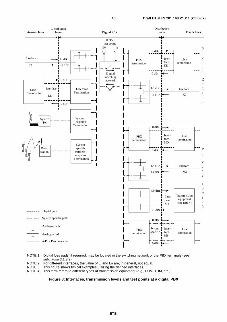
The test points shown in figure 3 are defined for specification purposes. They may not physically exist in a PBX but maybe accessed at the Access Point (AP) via the digital switching network. In this case, a part or all of the switchingnetwork will be included in the path from the PBX interface to the points of access to the test points.
NOTE: For more information see annex A, clause A.2.
ETSI
Draft ETSI ES 201 168 V1.2.1 (2000-07)12
3.1.2.2 PBX input and output
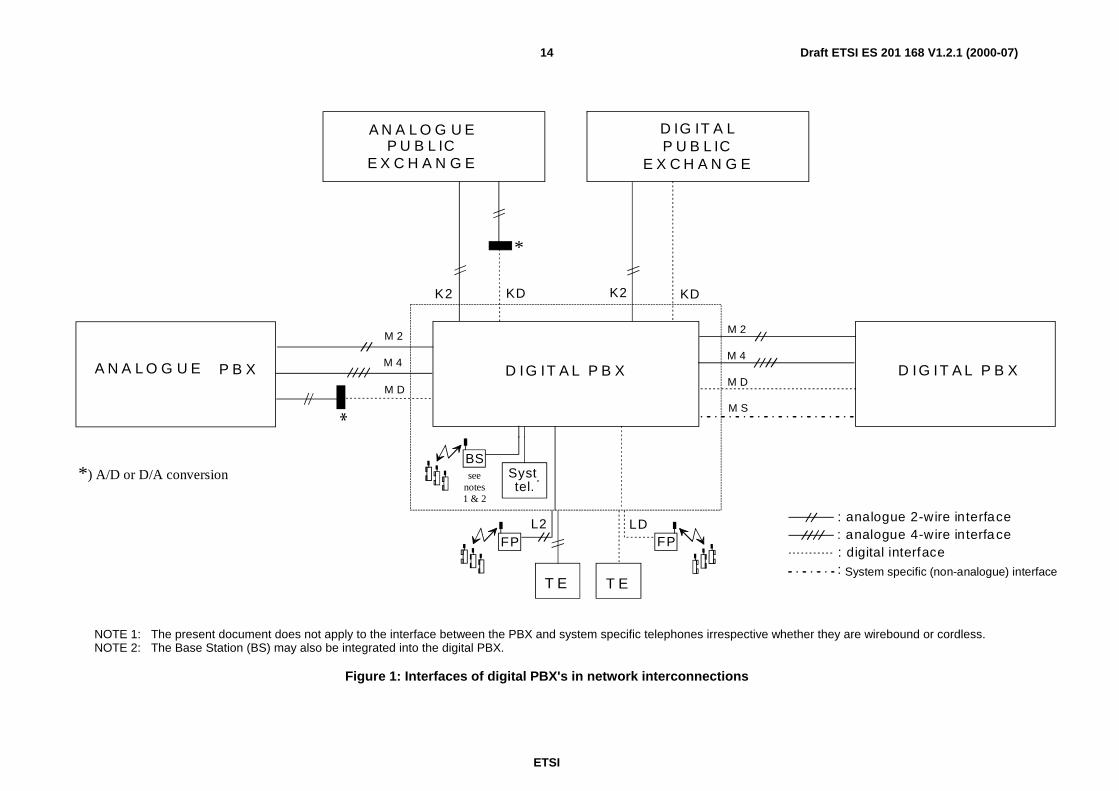
The PBX input and output for a connection through a digital PBX are located at the interfaces identified in clause 1 andshown in figures 1, 2 and 3.
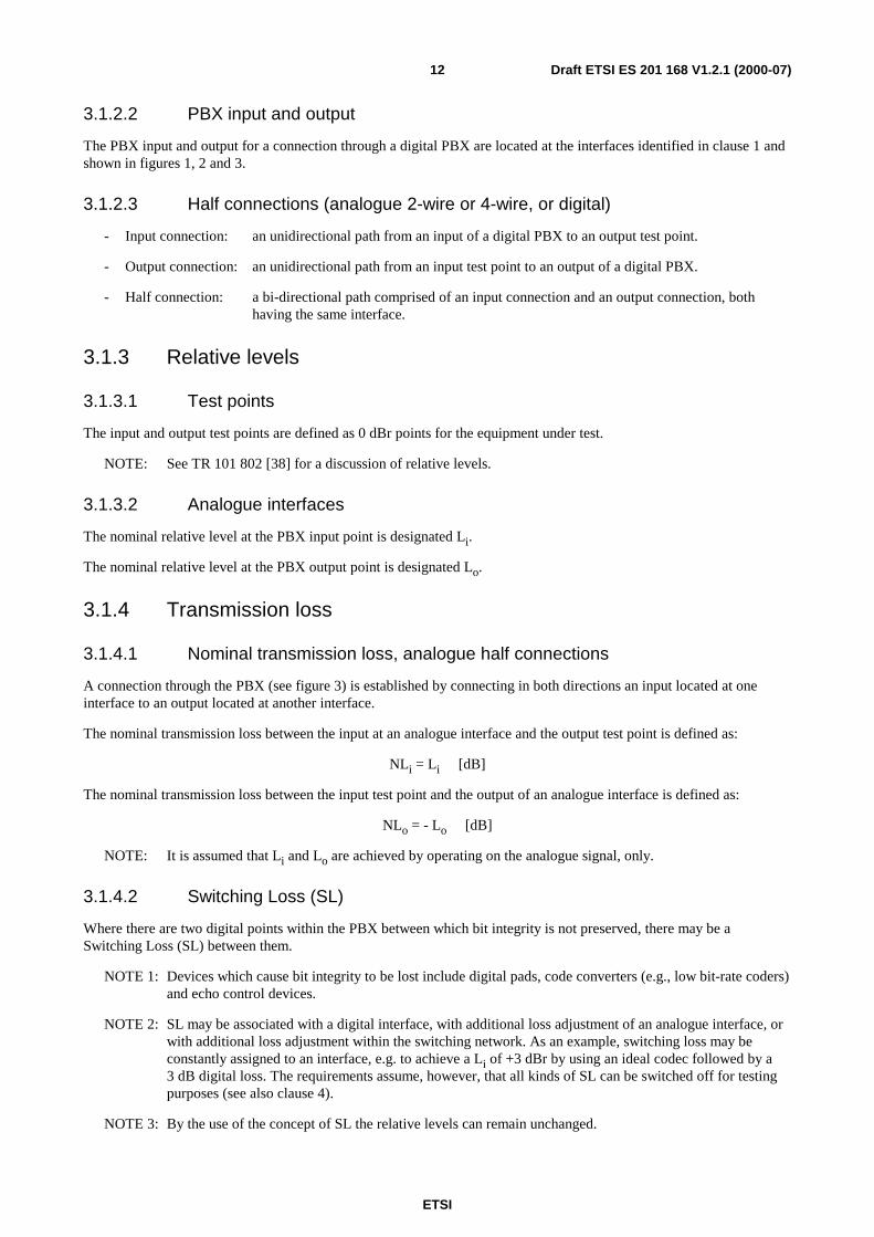
3.1.2.3 Half connections (analogue 2-wire or 4-wire, or digital)
- Input connection: an unidirectional path from an input of a digital PBX to an output test point.
- Output connection: an unidirectional path from an input test point to an output of a digital PBX.
- Half connection: a bi-directional path comprised of an input connection and an output connection, bothhaving the same interface.
3.1.3 Relative levels
3.1.3.1 Test points
The input and output test points are defined as 0 dBr points for the equipment under test.
NOTE: See TR 101 802 [38] for a discussion of relative levels.
3.1.3.2 Analogue interfaces
The nominal relative level at the PBX input point is designated Li.
The nominal relative level at the PBX output point is designated Lo.
3.1.4 Transmission loss
3.1.4.1 Nominal transmission loss, analogue half connections
A connection through the PBX (see figure 3) is established by connecting in both directions an input located at oneinterface to an output located at another interface.
The nominal transmission loss between the input at an analogue interface and the output test point is defined as:
NLi = Li [dB]
The nominal transmission loss between the input test point and the output of an analogue interface is defined as:
NLo = - Lo [dB]
NOTE: It is assumed that Li and Lo are achieved by operating on the analogue signal, only.
3.1.4.2 Switching Loss (SL)
Where there are two digital points within the PBX between which bit integrity is not preserved, there may be aSwitching Loss (SL) between them.
NOTE 1: Devices which cause bit integrity to be lost include digital pads, code converters (e.g., low bit-rate coders)and echo control devices.
NOTE 2: SL may be associated with a digital interface, with additional loss adjustment of an analogue interface, orwith additional loss adjustment within the switching network. As an example, switching loss may beconstantly assigned to an interface, e.g. to achieve a Li of +3 dBr by using an ideal codec followed by a3 dB digital loss. The requirements assume, however, that all kinds of SL can be switched off for testingpurposes (see also clause 4).
NOTE 3: By the use of the concept of SL the relative levels can remain unchanged.
ETSI
Draft ETSI ES 201 168 V1.2.1 (2000-07)13
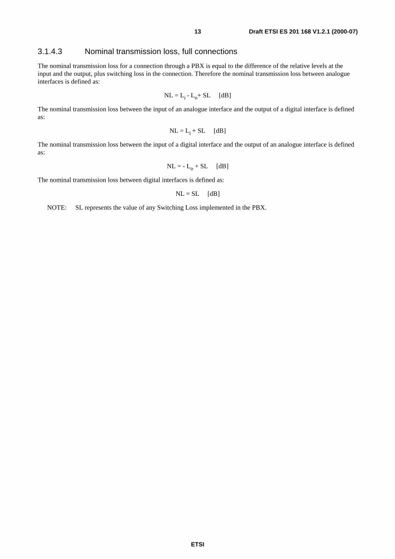
3.1.4.3 Nominal transmission loss, full connections
The nominal transmission loss for a connection through a PBX is equal to the difference of the relative levels at theinput and the output, plus switching loss in the connection. Therefore the nominal transmission loss between analogueinterfaces is defined as:
NL = Li - Lo+ SL [dB]
The nominal transmission loss between the input of an analogue interface and the output of a digital interface is definedas:
NL = Li + SL [dB]
The nominal transmission loss between the input of a digital interface and the output of an analogue interface is definedas:
NL = - Lo + SL [dB]
The nominal transmission loss between digital interfaces is defined as:
NL = SL [dB]
NOTE: SL represents the value of any Switching Loss implemented in the PBX.
ETSI
Draft ETSI ES 201 168 V1.2.1 (2000-07)14
T E T E
D IG IT A L P B X
D IG IT A LP U B L IC
E X C H A N G E
L2 LD
M 2
M 4
M D
FP
Syst.tel.
: analogue 4-wire interface: digital interface
M S
: System specific (non-analogue) interface
FP
BSsee
notes1 & 2
D IG IT A L P B X
KDK2
A N A L O G U EP U B L IC
E X C H A N G E
K2 KD
*
*) A/D or D/A conversion
M 2
M 4
M D
P B XA N A L O G U E*
: analogue 2-wire interface
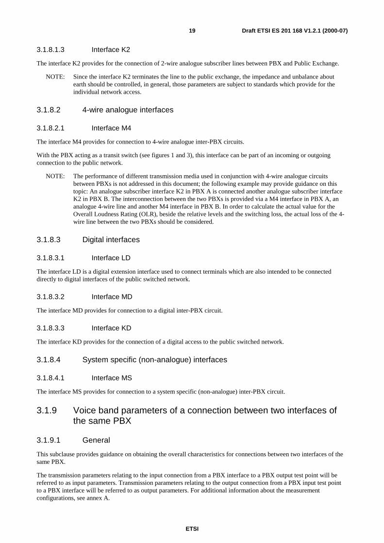
NOTE 1: The present document does not apply to the interface between the PBX and system specific telephones irrespective whether they are wirebound or cordless.NOTE 2: The Base Station (BS) may also be integrated into the digital PBX.
Figure 1: Interfaces of digital PBX's in network interconnections
ETSI
Draft ETSI ES 201 168 V1.2.1 (2000-07)15
T E T E
T E T E
D IG IT A L P B X
A N A L O G U EP B X
D IG IT A LP U B L IC
E X C H A N G E D IG IT A LP U B L IC
E X C H A N G E
D IG IT A LP B X
K D
L2 LD
L2 LD
M22
M21
KD K2
M 2 2
M 2 1
M 2 2
M D
M 2 2
M 2 2
M 2 1
M D
FP
Syst.tel.
: analogue 2-wire interface: digital interface
M S M S
: System specific (non-analogue) interface
FP
BSsee
notes1 & 2
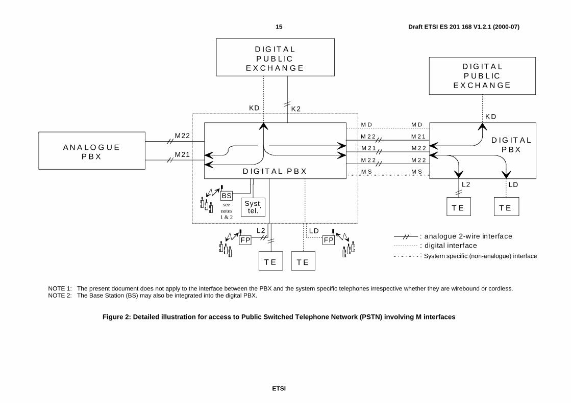
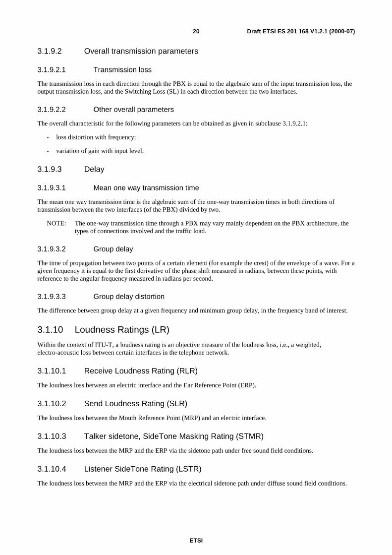
NOTE 1: The present document does not apply to the interface between the PBX and the system specific telephones irrespective whether they are wirebound or cordless.NOTE 2: The Base Station (BS) may also be integrated into the digital PBX.
Figure 2: Detailed illustration for access to Public Switched Telephone Network (PSTN) involving M interfaces
ETSI
Draft ETSI ES 201 168 V1.2.1 (2000-07)16
0 dBr
0 dBr
To Ti
Distributionframe Digital PBX
Interface
L2
Digitalswitchingnetwork
0 dBrtest points
0 dBr
0 dBr
PBXtermination
Inter-faceMD
Linetermination
Interface
LD
Extension lines
Li dBr
Inter-faceM4
Transmissionequipment(see note 4)
Lo dBr
Interface
K2
Lo dBr
Li dBr
Li dBr
Lo dBr
LineTermination
ExtensionTermination
Systemtelephone
Termination
Systemspecificcordless
telephoneTermination
SystemTel.
Basestation
0 dBr
0 dBr
PBXtermination
Inter-faceKD
Linetermination
Interface
M2
Lo dBr
Li dBr
Public
Domain
Private
Domain
Trunk linesDistribution
frame
Digital path
Analogue path
Analogue pad
A/D or D/A converter
System specific path0 dBr
0 dBr
PBXtermination
Inter-faceMS
Linetermination
Systemspecific
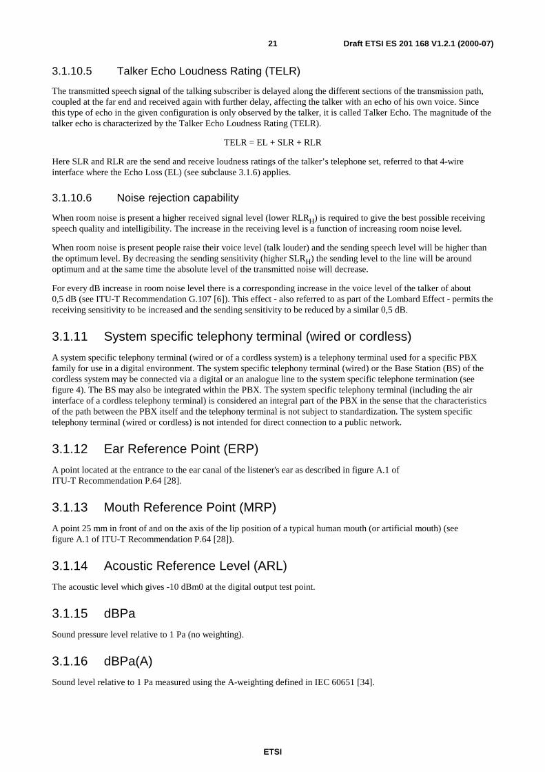
NOTE 1: Digital loss pads, if required, may be located in the switching network or the PBX terminals (seesubclause 3.1.3.2).
NOTE 2: For different interfaces, the value of Li and Lo are, in general, not equal.NOTE 3: This figure shows typical examples utilizing the defined interfaces.NOTE 4: This term refers to different types of transmission equipment (e.g., FDM, TDM, etc.).
Figure 3: Interfaces, transmission levels and test points at a digital PBX
ETSI
Draft ETSI ES 201 168 V1.2.1 (2000-07)17
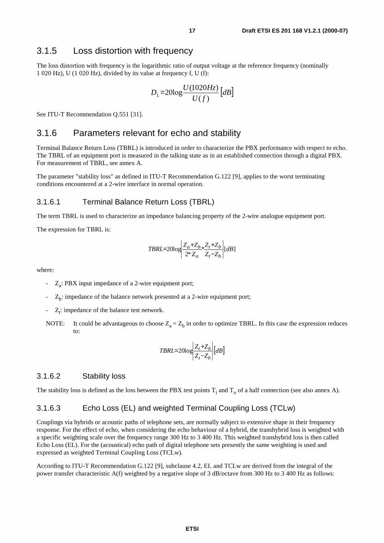
3.1.5 Loss distortion with frequency
The loss distortion with frequency is the logarithmic ratio of output voltage at the reference frequency (nominally1 020 Hz), U (1 020 Hz), divided by its value at frequency f, U (f):
[ ]dBfU
HzUDL )(
)1020(log20=
See ITU-T Recommendation Q.551 [31].
3.1.6 Parameters relevant for echo and stability
Terminal Balance Return Loss (TBRL) is introduced in order to characterize the PBX performance with respect to echo.The TBRL of an equipment port is measured in the talking state as in an established connection through a digital PBX.For measurement of TBRL, see annex A.
The parameter "stability loss" as defined in ITU-T Recommendation G.122 [9], applies to the worst terminatingconditions encountered at a 2-wire interface in normal operation.
3.1.6.1 Terminal Balance Return Loss (TBRL)
The term TBRL is used to characterize an impedance balancing property of the 2-wire analogue equipment port.
The expression for TBRL is:
][**2
log20 dBZZ
ZZ
Z
ZZTBRL
bt
bt
a
ba
−++=
where:
- Za: PBX input impedance of a 2-wire equipment port;
- Zb: impedance of the balance network presented at a 2-wire equipment port;
- Zt: impedance of the balance test network.
NOTE: It could be advantageous to choose Za = Zb in order to optimize TBRL. In this case the expression reducesto:
[ ]dBZZ
ZZTBRL
bt
bt
−+= log20
3.1.6.2 Stability loss
The stability loss is defined as the loss between the PBX test points Ti and To of a half connection (see also annex A).
3.1.6.3 Echo Loss (EL) and weighted Terminal Coupling Loss (TCLw)
Couplings via hybrids or acoustic paths of telephone sets, are normally subject to extensive shape in their frequencyresponse. For the effect of echo, when considering the echo behaviour of a hybrid, the transhybrid loss is weighted witha specific weighting scale over the frequency range 300 Hz to 3 400 Hz. This weighted transhybrid loss is then calledEcho Loss (EL). For the (acoustical) echo path of digital telephone sets presently the same weighting is used andexpressed as weighted Terminal Coupling Loss (TCLw).
According to ITU-T Recommendation G.122 [9], subclause 4.2, EL and TCLw are derived from the integral of thepower transfer characteristic A(f) weighted by a negative slope of 3 dB/octave from 300 Hz to 3 400 Hz as follows:
ETSI
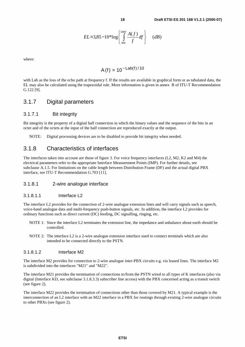
Draft ETSI ES 201 168 V1.2.1 (2000-07)18
)()(
log*1085,33400
300
dBdff
fAEL
−=
where:
A f Lab f( ) ( ) /= −10 10
with Lab as the loss of the echo path at frequency f. If the results are available in graphical form or as tabulated data, theEL may also be calculated using the trapezoidal rule. More information is given in annex B of ITU-T RecommendationG.122 [9].
3.1.7 Digital parameters
3.1.7.1 Bit integrity
Bit integrity is the property of a digital half connection in which the binary values and the sequence of the bits in anoctet and of the octets at the input of the half connection are reproduced exactly at the output.
NOTE: Digital processing devices are to be disabled to provide bit integrity when needed.
3.1.8 Characteristics of interfaces
The interfaces taken into account are those of figure 3. For voice frequency interfaces (L2, M2, K2 and M4) theelectrical parameters refer to the appropriate Interface Measurement Points (IMP). For further details, seesubclause A.1.5. For limitations on the cable length between Distribution Frame (DF) and the actual digital PBXinterface, see ITU-T Recommendation G.703 [11].
3.1.8.1 2-wire analogue interface
3.1.8.1.1 Interface L2
The interface L2 provides for the connection of 2-wire analogue extension lines and will carry signals such as speech,voice-band analogue data and multi-frequency push-button signals, etc. In addition, the interface L2 provides forordinary functions such as direct current (DC) feeding, DC signalling, ringing, etc.
NOTE 1: Since the interface L2 terminates the extension line, the impedance and unbalance about earth should becontrolled.
NOTE 2: The interface L2 is a 2-wire analogue extension interface used to connect terminals which are alsointended to be connected directly to the PSTN.
3.1.8.1.2 Interface M2
The interface M2 provides for connection to 2-wire analogue inter-PBX circuits e.g. via leased lines. The interface M2is subdivided into the interfaces "M21" and "M22".
The interface M21 provides the termination of connections to/from the PSTN wired to all types of K interfaces (also viadigital (Interface KD, see subclause 3.1.8.3.3) subscriber line access) with the PBX concerned acting as a transit switch(see figure 2).
The interface M22 provides the termination of connections other than those covered by M21. A typical example is theinterconnection of an L2 interface with an M22 interface in a PBX for routings through existing 2-wire analogue circuitsto other PBXs (see figure 2).
ETSI
Draft ETSI ES 201 168 V1.2.1 (2000-07)19
3.1.8.1.3 Interface K2
The interface K2 provides for the connection of 2-wire analogue subscriber lines between PBX and Public Exchange.
NOTE: Since the interface K2 terminates the line to the public exchange, the impedance and unbalance aboutearth should be controlled, in general, those parameters are subject to standards which provide for theindividual network access.
3.1.8.2 4-wire analogue interfaces
3.1.8.2.1 Interface M4
The interface M4 provides for connection to 4-wire analogue inter-PBX circuits.
With the PBX acting as a transit switch (see figures 1 and 3), this interface can be part of an incoming or outgoingconnection to the public network.
NOTE: The performance of different transmission media used in conjunction with 4-wire analogue circuitsbetween PBXs is not addressed in this document; the following example may provide guidance on thistopic: An analogue subscriber interface K2 in PBX A is connected another analogue subscriber interfaceK2 in PBX B. The interconnection between the two PBXs is provided via a M4 interface in PBX A, ananalogue 4-wire line and another M4 interface in PBX B. In order to calculate the actual value for theOverall Loudness Rating (OLR), beside the relative levels and the switching loss, the actual loss of the 4-wire line between the two PBXs should be considered.
3.1.8.3 Digital interfaces
3.1.8.3.1 Interface LD
The interface LD is a digital extension interface used to connect terminals which are also intended to be connecteddirectly to digital interfaces of the public switched network.
3.1.8.3.2 Interface MD
The interface MD provides for connection to a digital inter-PBX circuit.
3.1.8.3.3 Interface KD
The interface KD provides for the connection of a digital access to the public switched network.
3.1.8.4 System specific (non-analogue) interfaces
3.1.8.4.1 Interface MS
The interface MS provides for connection to a system specific (non-analogue) inter-PBX circuit.
3.1.9 Voice band parameters of a connection between two interfaces ofthe same PBX
3.1.9.1 General
This subclause provides guidance on obtaining the overall characteristics for connections between two interfaces of thesame PBX.
The transmission parameters relating to the input connection from a PBX interface to a PBX output test point will bereferred to as input parameters. Transmission parameters relating to the output connection from a PBX input test pointto a PBX interface will be referred to as output parameters. For additional information about the measurementconfigurations, see annex A.
ETSI
Draft ETSI ES 201 168 V1.2.1 (2000-07)20
3.1.9.2 Overall transmission parameters
3.1.9.2.1 Transmission loss
The transmission loss in each direction through the PBX is equal to the algebraic sum of the input transmission loss, theoutput transmission loss, and the Switching Loss (SL) in each direction between the two interfaces.
3.1.9.2.2 Other overall parameters
The overall characteristic for the following parameters can be obtained as given in subclause 3.1.9.2.1:
- loss distortion with frequency;
- variation of gain with input level.
3.1.9.3 Delay
3.1.9.3.1 Mean one way transmission time
The mean one way transmission time is the algebraic sum of the one-way transmission times in both directions oftransmission between the two interfaces (of the PBX) divided by two.
NOTE: The one-way transmission time through a PBX may vary mainly dependent on the PBX architecture, thetypes of connections involved and the traffic load.
3.1.9.3.2 Group delay
The time of propagation between two points of a certain element (for example the crest) of the envelope of a wave. For agiven frequency it is equal to the first derivative of the phase shift measured in radians, between these points, withreference to the angular frequency measured in radians per second.
3.1.9.3.3 Group delay distortion
The difference between group delay at a given frequency and minimum group delay, in the frequency band of interest.
3.1.10 Loudness Ratings (LR)
Within the context of ITU-T, a loudness rating is an objective measure of the loudness loss, i.e., a weighted,electro-acoustic loss between certain interfaces in the telephone network.
3.1.10.1 Receive Loudness Rating (RLR)
The loudness loss between an electric interface and the Ear Reference Point (ERP).
3.1.10.2 Send Loudness Rating (SLR)
The loudness loss between the Mouth Reference Point (MRP) and an electric interface.
3.1.10.3 Talker sidetone, SideTone Masking Rating (STMR)
The loudness loss between the MRP and the ERP via the sidetone path under free sound field conditions.
3.1.10.4 Listener SideTone Rating (LSTR)
The loudness loss between the MRP and the ERP via the electrical sidetone path under diffuse sound field conditions.
ETSI
Draft ETSI ES 201 168 V1.2.1 (2000-07)21
3.1.10.5 Talker Echo Loudness Rating (TELR)
The transmitted speech signal of the talking subscriber is delayed along the different sections of the transmission path,coupled at the far end and received again with further delay, affecting the talker with an echo of his own voice. Sincethis type of echo in the given configuration is only observed by the talker, it is called Talker Echo. The magnitude of thetalker echo is characterized by the Talker Echo Loudness Rating (TELR).
TELR = EL + SLR + RLR
Here SLR and RLR are the send and receive loudness ratings of the talker’s telephone set, referred to that 4-wireinterface where the Echo Loss (EL) (see subclause 3.1.6) applies.
3.1.10.6 Noise rejection capability
When room noise is present a higher received signal level (lower RLRH) is required to give the best possible receivingspeech quality and intelligibility. The increase in the receiving level is a function of increasing room noise level.
When room noise is present people raise their voice level (talk louder) and the sending speech level will be higher thanthe optimum level. By decreasing the sending sensitivity (higher SLRH) the sending level to the line will be aroundoptimum and at the same time the absolute level of the transmitted noise will decrease.
For every dB increase in room noise level there is a corresponding increase in the voice level of the talker of about0,5 dB (see ITU-T Recommendation G.107 [6]). This effect - also referred to as part of the Lombard Effect - permits thereceiving sensitivity to be increased and the sending sensitivity to be reduced by a similar 0,5 dB.
3.1.11 System specific telephony terminal (wired or cordless)
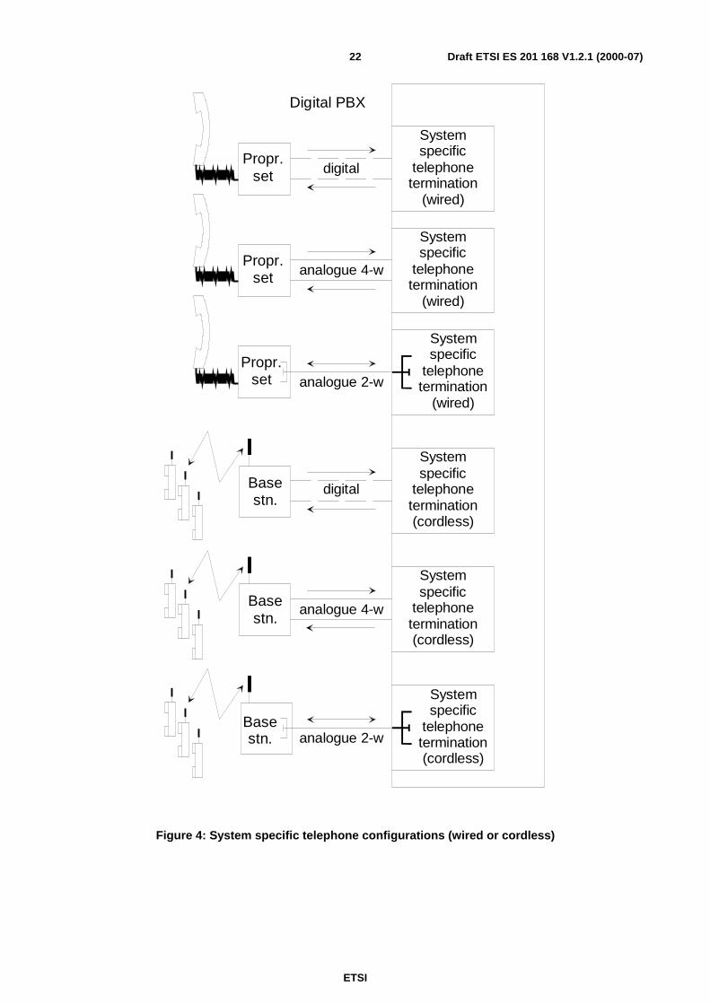
A system specific telephony terminal (wired or of a cordless system) is a telephony terminal used for a specific PBXfamily for use in a digital environment. The system specific telephony terminal (wired) or the Base Station (BS) of thecordless system may be connected via a digital or an analogue line to the system specific telephone termination (seefigure 4). The BS may also be integrated within the PBX. The system specific telephony terminal (including the airinterface of a cordless telephony terminal) is considered an integral part of the PBX in the sense that the characteristicsof the path between the PBX itself and the telephony terminal is not subject to standardization. The system specifictelephony terminal (wired or cordless) is not intended for direct connection to a public network.
3.1.12 Ear Reference Point (ERP)
A point located at the entrance to the ear canal of the listener's ear as described in figure A.1 ofITU-T Recommendation P.64 [28].
3.1.13 Mouth Reference Point (MRP)
A point 25 mm in front of and on the axis of the lip position of a typical human mouth (or artificial mouth) (seefigure A.1 of ITU-T Recommendation P.64 [28]).
3.1.14 Acoustic Reference Level (ARL)
The acoustic level which gives -10 dBm0 at the digital output test point.
3.1.15 dBPa
Sound pressure level relative to 1 Pa (no weighting).
3.1.16 dBPa(A)
Sound level relative to 1 Pa measured using the A-weighting defined in IEC 60651 [34].
ETSI
Draft ETSI ES 201 168 V1.2.1 (2000-07)22
Basestn.
Propr.set
Propr.set
Propr.set
Basestn.
Basestn.
Systemspecific
telephonetermination
(wired)
Systemspecific
telephonetermination
(wired)
Systemspecific
telephonetermination
(wired)
Systemspecific
telephonetermination(cordless)
Systemspecific
telephonetermination(cordless)
Systemspecific
telephonetermination(cordless)
Digital PBX
analogue 4-w
analogue 2-w
digital
analogue 2-w
analogue 4-w
digital
Figure 4: System specific telephone configurations (wired or cordless)
ETSI
Draft ETSI ES 201 168 V1.2.1 (2000-07)23
3.2 AbbreviationsFor the purposes of the present document, the following abbreviations apply:
AC Alternating CurrentAP Access PointAPC Access Point ConnectionARL Acoustic Reference LevelBS Base StationDC Direct CurrentDF Distribution FrameDRS Digital Reference SequenceDTS Digital Test SequenceEL Echo Lossemf electro motoric forceERP Ear Reference PointFDM Frequency Division MultiplexFEXT Far End CrosstalkFFT Fast Fourier TransformationIMP Interface Measurement PointIP Internet ProtocolIUT Interface Under TestLCL Longitudinal Conversion LossLCTL Longitudinal Conversion Transfer LossLD Loss DistortionLR Loudness RatingLRGP Loudness Rating Guard ring PositionLSTR Listener SideTone RatingLSTRcorr corrected LSTR valueLSTRmeas measured LSTR valueMNRU Modulated Noise Reference UnitMRP Mouth Reference PointNEXT Near End CrosstalkNL Nominal (Transmission) LossNS Not SpecifiedPBN Private Branch NetworkPBX Private Branch eXchangePCM Pulse Code ModulationPP Portable PartPSTN Public Switched Telephone Networkqdu quantizing distortion unitRLH Return Loss HybridRLR Receive Loudness RatingRLRmeas measured RLR valueRLRnom declared nominal RLR valuerms root mean squareRPP Reference Portable PartSL Switching LossSLR Send Loudness RatingSLRmeas measured SLR valueSLRnom declared nominal SLR valueSTMR SideTone Masking RatingSTMRcorr corrected STMR valueSTMRmeas measured STMR valueTBRL Terminal Balance Return LossTCLw weighted Terminal Coupling LossTDU Transmission Decoupling UnitTEI Test Equipment InterfaceTELR Talker Echo Loudness RatingTRP Transmission Reference Point
ETSI
Draft ETSI ES 201 168 V1.2.1 (2000-07)24
4 Compliance principlesAll digital signal processing devices, which affect bit integrity of the 64 kbit/s speech-path within a digital PBX, e.g.,digital loss or gain, low bit-rate coders, digital echo control devices etc., shall be rendered inoperative, when measuringthe transmission parameters of the present document. However, if the NL or the SLR and RLR of a systems specifictelephone set are implemented by a digital loss or gain, the parameters "Nominal value" and "Tolerance" of the relativelevels for input and output connections and of the SLR and RLR, respectively shall be measured with digital loss or gainswitched operative.
NOTE: In some digital PBXs such a digital loss or gain might be realized in a way, that it is not possible to switchthis digital signal processing inoperative during measurement. However, several transmission parameterslike quantizing distortion, variation of gain with input level etc., will be influenced additionally by digitalsignal processing. This means, the existing limits in the present document - derived only for the process ofencoding/decoding - may not be met.
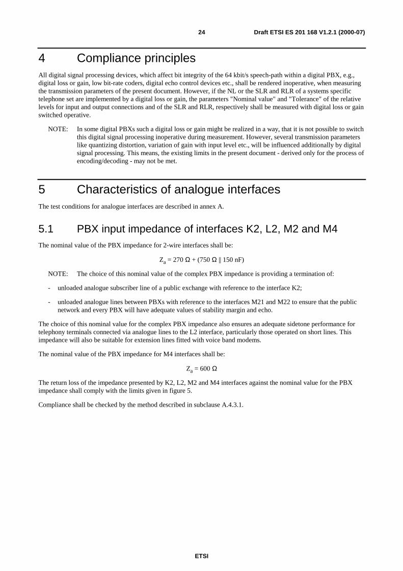
5 Characteristics of analogue interfacesThe test conditions for analogue interfaces are described in annex A.
5.1 PBX input impedance of interfaces K2, L2, M2 and M4The nominal value of the PBX impedance for 2-wire interfaces shall be:
Za = 270 Ω + (750 Ω || 150 nF)
NOTE: The choice of this nominal value of the complex PBX impedance is providing a termination of:
- unloaded analogue subscriber line of a public exchange with reference to the interface K2;
- unloaded analogue lines between PBXs with reference to the interfaces M21 and M22 to ensure that the publicnetwork and every PBX will have adequate values of stability margin and echo.
The choice of this nominal value for the complex PBX impedance also ensures an adequate sidetone performance fortelephony terminals connected via analogue lines to the L2 interface, particularly those operated on short lines. Thisimpedance will also be suitable for extension lines fitted with voice band modems.
The nominal value of the PBX impedance for M4 interfaces shall be:
Za = 600 Ω
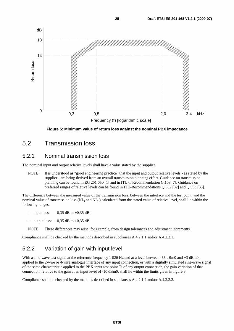
The return loss of the impedance presented by K2, L2, M2 and M4 interfaces against the nominal value for the PBXimpedance shall comply with the limits given in figure 5.
Compliance shall be checked by the method described in subclause A.4.3.1.
ETSI
Draft ETSI ES 201 168 V1.2.1 (2000-07)25
0,3 2,0 3,4
Frequency (f) [logarithmic scale]
Ret
urn
loss
kHz
18
14
dB
0,50
Figure 5: Minimum value of return loss against the nominal PBX impedance
5.2 Transmission loss
5.2.1 Nominal transmission loss
The nominal input and output relative levels shall have a value stated by the supplier.
NOTE: It is understood as "good engineering practice" that the input and output relative levels - as stated by thesupplier - are being derived from an overall transmission planning effort. Guidance on transmissionplanning can be found in EG 201 050 [1] and in ITU-T Recommendation G.108 [7]. Guidance onpreferred ranges of relative levels can be found in ITU-Recommendations Q.552 [32] and Q.553 [33].
The difference between the measured value of the transmission loss, between the interface and the test point, and thenominal value of transmission loss (NLi and NLo) calculated from the stated value of relative level, shall lie within thefollowing ranges:
- input loss: -0,35 dB to +0,35 dB;
- output loss: -0,35 dB to +0,35 dB.
NOTE: These differences may arise, for example, from design tolerances and adjustment increments.
Compliance shall be checked by the methods described in subclauses A.4.2.1.1 and/or A.4.2.2.1.
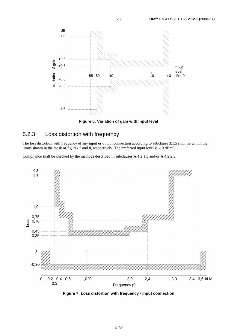
5.2.2 Variation of gain with input level
With a sine-wave test signal at the reference frequency 1 020 Hz and at a level between -55 dBm0 and +3 dBm0,applied to the 2-wire or 4-wire analogue interface of any input connection, or with a digitally simulated sine-wave signalof the same characteristic applied to the PBX input test point Ti of any output connection, the gain variation of thatconnection, relative to the gain at an input level of -10 dBm0, shall lie within the limits given in figure 6.
Compliance shall be checked by the methods described in subclauses A.4.2.1.2 and/or A.4.2.2.2.
ETSI
Draft ETSI ES 201 168 V1.2.1 (2000-07)26
+3-10-40-55
InputleveldBm0
-1,6
-0,6
+0,6
+1,6
dB
-50-0,3
+0,3
Var
iatio
nof
gain
Figure 6: Variation of gain with input level
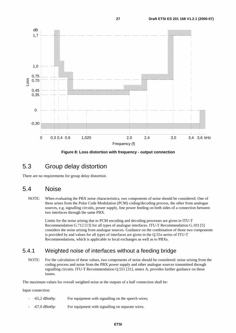
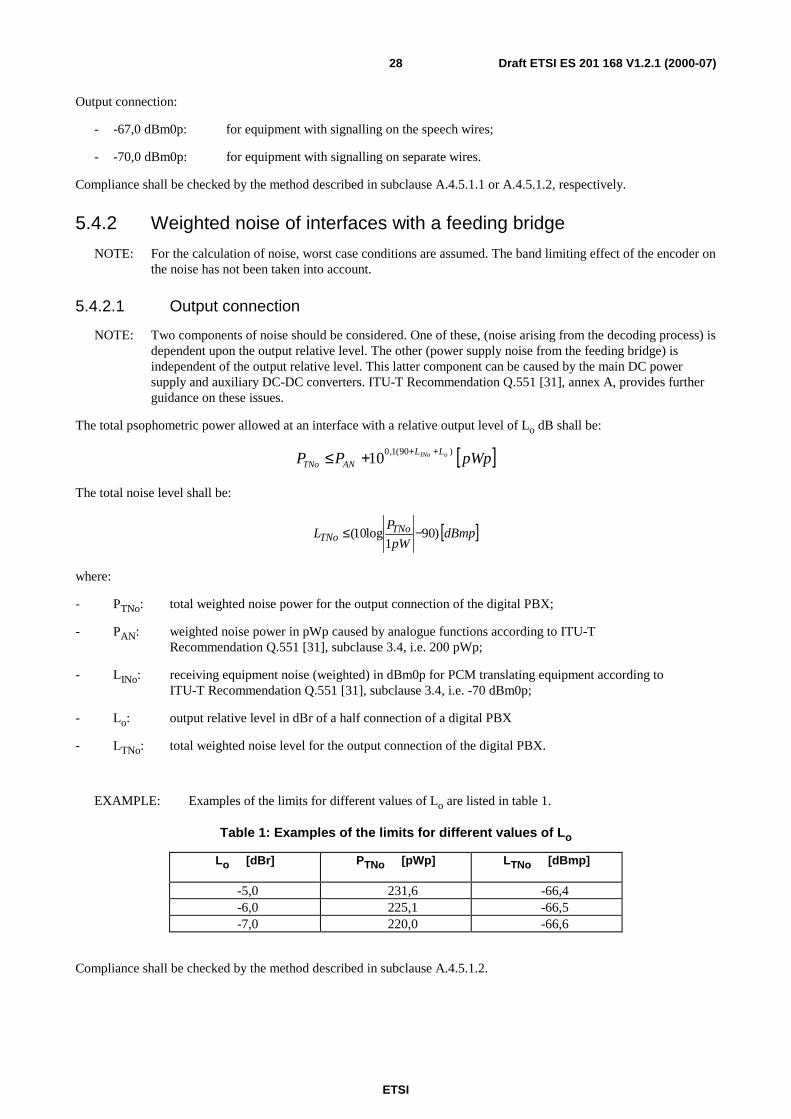
5.2.3 Loss distortion with frequency
The loss distortion with frequency of any input or output connection according to subclause 3.1.5 shall lie within thelimits shown in the mask of figures 7 and 8, respectively. The preferred input level is -10 dBm0.
Compliance shall be checked by the methods described in subclauses A.4.2.1.3 and/or A.4.2.2.3.
0,4 1,020 2,0 2,4 3,0 3,4 3,6 kHz
0,350,45
0
-0,30
0,700,75
1,0
1,7dB
0,6
Frequency (f)
Loss
0,20,3
0
Figure 7: Loss distortion with frequency - input connection
ETSI
Draft ETSI ES 201 168 V1.2.1 (2000-07)27
0,4 1,020 2,0 2,4 3,0 3,4 3,6 kHz
0,350,45
0
-0,30
0,700,75
1,0
1,7dB
0,60,3
Frequency (f)
Loss
0
Figure 8: Loss distortion with frequency - output connection
5.3 Group delay distortionThere are no requirements for group delay distortion.
5.4 NoiseNOTE: When evaluating the PBX noise characteristics, two components of noise should be considered. One of
these arises from the Pulse Code Modulation (PCM) coding/decoding process, the other from analoguesources, e.g. signalling circuits, power supply, line power feeding on both sides of a connection betweentwo interfaces through the same PBX.
Limits for the noise arising due to PCM encoding and decoding processes are given in ITU-TRecommendation G.712 [13] for all types of analogue interfaces. ITU-T Recommendation G.103 [5]considers the noise arising from analogue sources. Guidance on the combination of those two componentsis provided by and values for all types of interfaces are given in the Q.55x-series of ITU-TRecommendations, which is applicable to local exchanges as well as to PBXs.
5.4.1 Weighted noise of interfaces without a feeding bridge
NOTE: For the calculation of these values, two components of noise should be considered: noise arising from thecoding process and noise from the PBX power supply and other analogue sources transmitted throughsignalling circuits. ITU-T Recommendation Q.551 [31], annex A, provides further guidance on theseissues.
The maximum values for overall weighted noise at the outputs of a half connection shall be:
Input connection:
- -65,2 dBm0p: For equipment with signalling on the speech wires;
- -67,0 dBm0p: For equipment with signalling on separate wires.
ETSI
Draft ETSI ES 201 168 V1.2.1 (2000-07)28
Output connection:
- -67,0 dBm0p: for equipment with signalling on the speech wires;
- -70,0 dBm0p: for equipment with signalling on separate wires.
Compliance shall be checked by the method described in subclause A.4.5.1.1 or A.4.5.1.2, respectively.
5.4.2 Weighted noise of interfaces with a feeding bridge
NOTE: For the calculation of noise, worst case conditions are assumed. The band limiting effect of the encoder onthe noise has not been taken into account.
5.4.2.1 Output connection
NOTE: Two components of noise should be considered. One of these, (noise arising from the decoding process) isdependent upon the output relative level. The other (power supply noise from the feeding bridge) isindependent of the output relative level. This latter component can be caused by the main DC powersupply and auxiliary DC-DC converters. ITU-T Recommendation Q.551 [31], annex A, provides furtherguidance on these issues.
The total psophometric power allowed at an interface with a relative output level of Lo dB shall be:
[ ]pWpPP oINo LL
ANTNo
)90(1,010
+++≤
The total noise level shall be:
[ ]dBmppW
PL TNo
TNo )901
log10( −≤
where:
- PTNo: total weighted noise power for the output connection of the digital PBX;
- PAN: weighted noise power in pWp caused by analogue functions according to ITU-TRecommendation Q.551 [31], subclause 3.4, i.e. 200 pWp;
- LINo: receiving equipment noise (weighted) in dBm0p for PCM translating equipment according toITU-T Recommendation Q.551 [31], subclause 3.4, i.e. -70 dBm0p;
- Lo: output relative level in dBr of a half connection of a digital PBX
- LTNo: total weighted noise level for the output connection of the digital PBX.
EXAMPLE: Examples of the limits for different values of Lo are listed in table 1.
Table 1: Examples of the limits for different values of Lo
Lo [dBr] PTNo [pWp] LTNo [dBmp]
-5,0 231,6 -66,4-6,0 225,1 -66,5-7,0 220,0 -66,6
Compliance shall be checked by the method described in subclause A.4.5.1.2.
ETSI
Draft ETSI ES 201 168 V1.2.1 (2000-07)29
5.4.2.2 Input connection
NOTE: Two components of noise should be considered. One of these (noise arising from the encoding process) isdependent upon the input relative level. The other (power supply noise from the feeding bridge) shall becorrected by the input relative level for calculation at the PBX output test point To.. ITU-TRecommendation Q.551 [31], annex A, provides further guidance on these issues.
The total psophometric power allowed at the PBX output test point To with a relative input level of Li shall be:
[ ]ppWPP INii LLANTNi 01010 )90(1,01,0 +− +∗≤
and the total noise level shall be:
[ ]pdBmpW
PL TNi
TNi 0)901
log10( −≤
where:
- PTNi: total weighted noise power for the input connection of the digital PBX;
- PAN: weighted noise power in pWp caused by analogue functions according to ITU-TRecommendation Q.551 [31], subclause 3.4, i.e. 200 pWp;
- LINi: idle channel noise (weighted) in dBm0p for the input connection of a digital PBX according toITU-T Recommendation Q.551 [31], subclause 3.4, i.e. -67 dBm0p;
- Li: input relative level in dBr of a half connection of a digital PBX;
- LTNi: total weighted noise level for the input connection of the digital PBX.
EXAMPLE: Examples of the limits for different values of Lo are listed in table 2.
Table 2: Examples of the limits for different values of Li
Li [dBr] PTNi [pW0p] LTNi [dBm0p]
0 399,5 -64,0
+1,0 358,4 -64,5
+2,0 325,7 -64,9
Compliance shall be checked by the method described in subclause A.4.5.1.1.
5.4.3 Single frequency noise of interfaces K2, L2, M2 and M4
The level of any unwanted single frequency (in particular the sampling frequency and its multiples), measuredselectively with a bandwidth of 80 Hz in the frequency range from 4 kHz to 72 kHz at the interface of an outputconnection shall not exceed -50 dBm0.
NOTE: In this case "unwanted" refers to self generated noise such as feed-through of sampling frequencies andnot to tones used for signalling or for normal traffic.
Compliance shall be checked by the method described in subclause A.5.1.4.
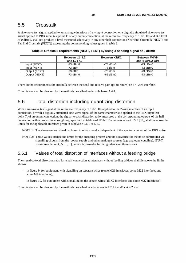
ETSI
Draft ETSI ES 201 168 V1.2.1 (2000-07)30
5.5 CrosstalkA sine-wave test signal applied to an analogue interface of any input connection or a digitally simulated sine-wave testsignal applied to PBX input test point Ti of any output connection, at the reference frequency of 1 020 Hz and at a levelof 0 dBm0, shall not produce a level measured selectively in any other half connection (Near End Crosstalk (NEXT) andFar End Crosstalk (FEXT)) exceeding the corresponding values given in table 3.
Table 3: Crosstalk requirements (NEXT, FEXT) by using a sending signal of 0 dBm0
Between L2 / L2and L2 / K2
Between K2/K2 Between M4/M4and 4-wire/2-wire
Input (FEXT) -73 dBm0 -73 dBm0 -73 dBm0Input (NEXT) -73 dBm -73 dBm -73 dBm0Output (FEXT) -73 dBm -73 dBm -73 dBm0Output (NEXT) -73 dBm0 -66 dBm0 -73 dBm0
There are no requirements for crosstalk between the send and receive path (go-to-return) on a 4-wire interface.
Compliance shall be checked by the methods described under subclause A.4.4.
5.6 Total distortion including quantizing distortionWith a sine-wave test signal at the reference frequency of 1 020 Hz applied to the 2-wire interface of an inputconnection, or with a digitally simulated sine-wave signal of the same characteristic applied to the PBX input testpoint Ti of an output connection, the signal-to-total distortion ratio, measured at the corresponding outputs of the halfconnection with a proper noise weighting, specified in table 4 of ITU-T Recommendation G.223 [10], shall lie above thelimits for the applicable interface given in subclause 5.6.1 or 5.6.2.
NOTE 1: The sinewave test signal is chosen to obtain results independent of the spectral content of the PBX noise.
NOTE 2: These values include the limits for the encoding process and the allowance for the noise contributed viasignalling circuits from the power supply and other analogue sources (e.g. analogue coupling). ITU-TRecommendation Q.551 [31], annex A, provides further guidance on these issues.
5.6.1 Values of total distortion of interfaces without a feeding bridge
The signal-to-total distortion ratio for a half connection at interfaces without feeding bridges shall lie above the limitsshown:
- in figure 9, for equipment with signalling on separate wires (some M21 interfaces, some M22 interfaces andsome M4 interfaces);
- in figure 10, for equipment with signalling on the speech wires (all K2 interfaces and some M22 interfaces).
Compliance shall be checked by the methods described in subclauses A.4.2.1.4 and/or A.4.2.2.4.
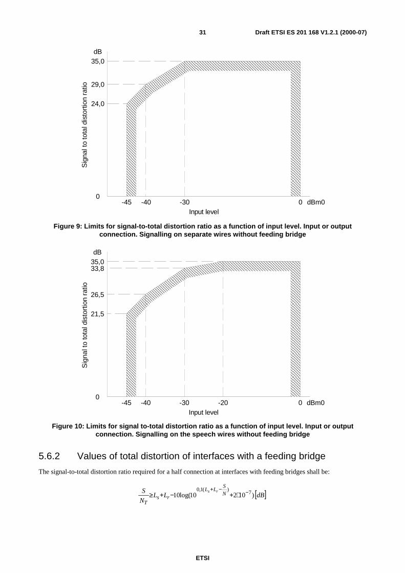
ETSI
Draft ETSI ES 201 168 V1.2.1 (2000-07)31
35,0dB
0-45 -40 -30 0 dBm0
Input level
Sig
nalt
oto
tald
isto
rtio
nra
tio 29,0
24,0
Figure 9: Limits for signal-to-total distortion ratio as a function of input level. Input or outputconnection. Signalling on separate wires without feeding bridge
35,033,8
26,5
21,5
dB
0-45 -40 -30 -20 0 dBm0
Input level
Sig
nalt
oto
tald
isto
rtio
nra
tio
Figure 10: Limits for signal to-total distortion ratio as a function of input level. Input or outputconnection. Signalling on the speech wires without feeding bridge
5.6.2 Values of total distortion of interfaces with a feeding bridge
The signal-to-total distortion ratio required for a half connection at interfaces with feeding bridges shall be:
[ ]dBLLN
S N
SLL
rsT
rs)10210(log10 7)(1,0 −−+
∗+−+≥
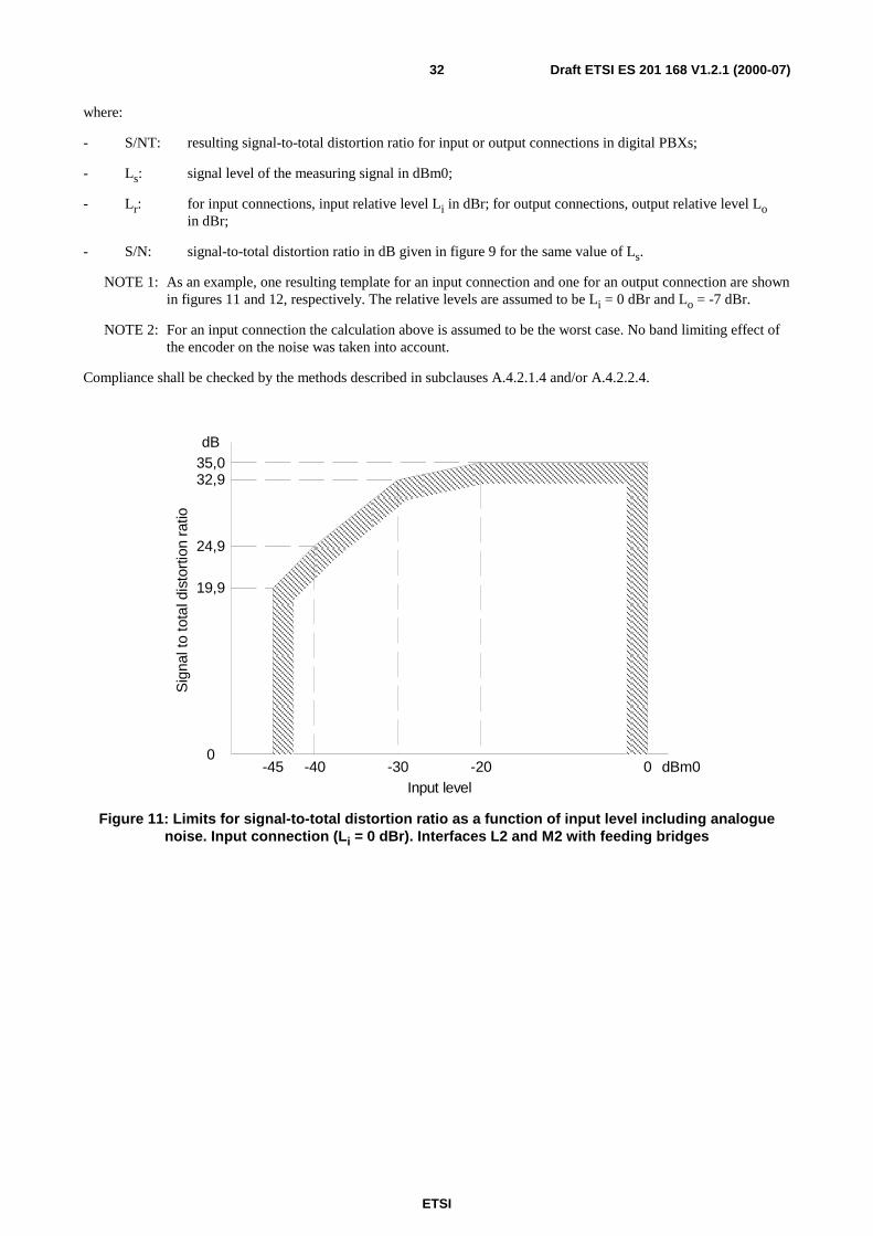
ETSI
Draft ETSI ES 201 168 V1.2.1 (2000-07)32
where:
- S/NT: resulting signal-to-total distortion ratio for input or output connections in digital PBXs;
- Ls: signal level of the measuring signal in dBm0;
- Lr: for input connections, input relative level Li in dBr; for output connections, output relative level Loin dBr;
- S/N: signal-to-total distortion ratio in dB given in figure 9 for the same value of Ls.
NOTE 1: As an example, one resulting template for an input connection and one for an output connection are shownin figures 11 and 12, respectively. The relative levels are assumed to be Li = 0 dBr and Lo = -7 dBr.
NOTE 2: For an input connection the calculation above is assumed to be the worst case. No band limiting effect ofthe encoder on the noise was taken into account.
Compliance shall be checked by the methods described in subclauses A.4.2.1.4 and/or A.4.2.2.4.
35,0dB
0-45 -40 -30 0 dBm0
Input level
Sig
nalt
oto
tald
isto
rtio
nra
tio
-20
32,9
24,9
19,9
Figure 11: Limits for signal-to-total distortion ratio as a function of input level including analoguenoise. Input connection (Li = 0 dBr). Interfaces L2 and M2 with feeding bridges
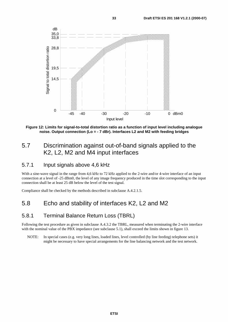
ETSI
Draft ETSI ES 201 168 V1.2.1 (2000-07)33
35,0dB
0-45 -40 -30 0 dBm0
Input level
Sig
nalt
oto
tald
isto
rtio
nra
tio
-20 -10
33,8
28,8
19,5
14,5
Figure 12: Limits for signal-to-total distortion ratio as a function of input level including analoguenoise. Output connection (Lo = - 7 dBr). Interfaces L2 and M2 with feeding bridges
5.7 Discrimination against out-of-band signals applied to theK2, L2, M2 and M4 input interfaces
5.7.1 Input signals above 4,6 kHz
With a sine-wave signal in the range from 4,6 kHz to 72 kHz applied to the 2-wire and/or 4-wire interface of an inputconnection at a level of -25 dBm0, the level of any image frequency produced in the time slot corresponding to the inputconnection shall be at least 25 dB below the level of the test signal.
Compliance shall be checked by the methods described in subclause A.4.2.1.5.
5.8 Echo and stability of interfaces K2, L2 and M2
5.8.1 Terminal Balance Return Loss (TBRL)
Following the test procedure as given in subclause A.4.3.2 the TBRL, measured when terminating the 2-wire interfacewith the nominal value of the PBX impedance (see subclause 5.1), shall exceed the limits shown in figure 13.
NOTE: In special cases (e.g. very long lines, loaded lines, level controlled (by line feeding) telephone sets) itmight be necessary to have special arrangements for the line balancing network and the test network.
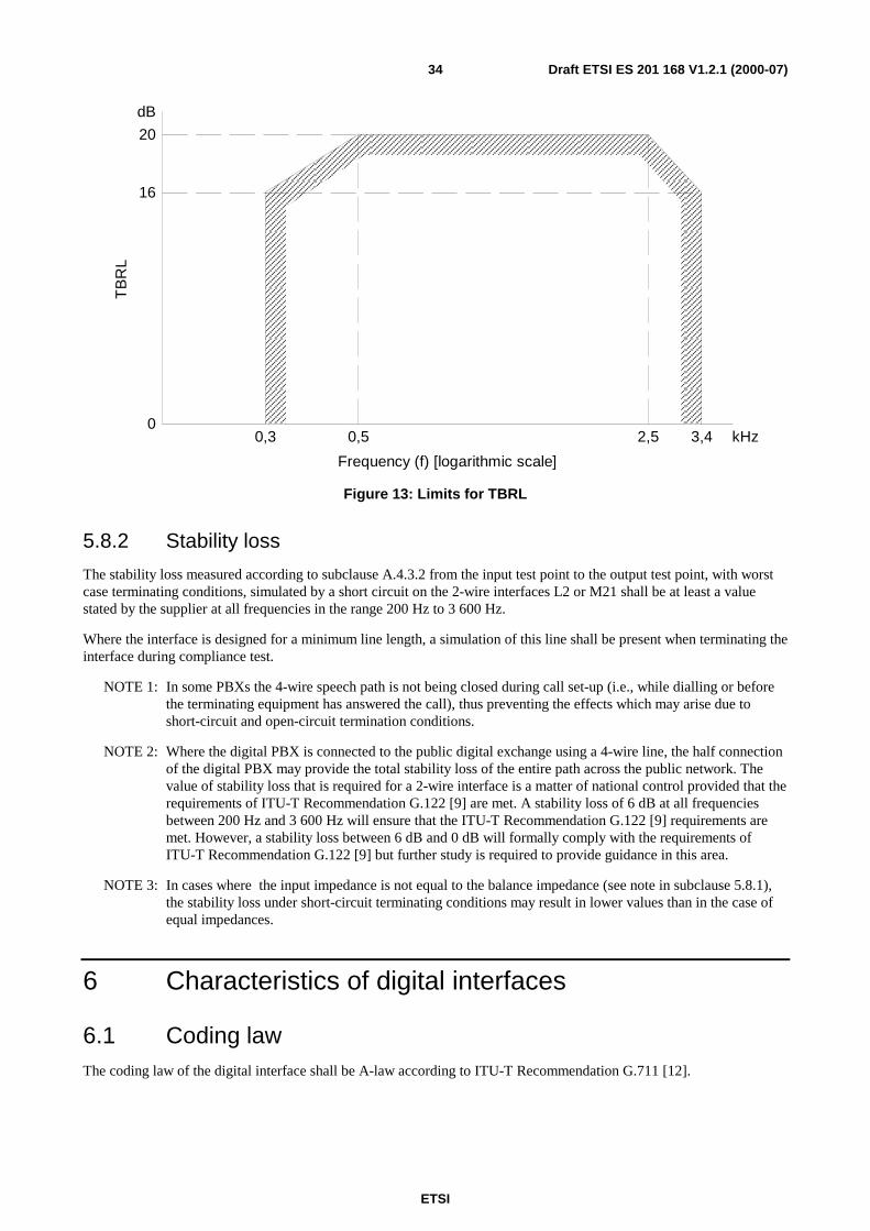
ETSI
Draft ETSI ES 201 168 V1.2.1 (2000-07)34
0,3 3,4
Frequency (f) [logarithmic scale]
TB
RL
kHz
dB
0,5
20
16
2,50
Figure 13: Limits for TBRL
5.8.2 Stability loss
The stability loss measured according to subclause A.4.3.2 from the input test point to the output test point, with worstcase terminating conditions, simulated by a short circuit on the 2-wire interfaces L2 or M21 shall be at least a valuestated by the supplier at all frequencies in the range 200 Hz to 3 600 Hz.
Where the interface is designed for a minimum line length, a simulation of this line shall be present when terminating theinterface during compliance test.
NOTE 1: In some PBXs the 4-wire speech path is not being closed during call set-up (i.e., while dialling or beforethe terminating equipment has answered the call), thus preventing the effects which may arise due toshort-circuit and open-circuit termination conditions.
NOTE 2: Where the digital PBX is connected to the public digital exchange using a 4-wire line, the half connectionof the digital PBX may provide the total stability loss of the entire path across the public network. Thevalue of stability loss that is required for a 2-wire interface is a matter of national control provided that therequirements of ITU-T Recommendation G.122 [9] are met. A stability loss of 6 dB at all frequenciesbetween 200 Hz and 3 600 Hz will ensure that the ITU-T Recommendation G.122 [9] requirements aremet. However, a stability loss between 6 dB and 0 dB will formally comply with the requirements ofITU-T Recommendation G.122 [9] but further study is required to provide guidance in this area.
NOTE 3: In cases where the input impedance is not equal to the balance impedance (see note in subclause 5.8.1),the stability loss under short-circuit terminating conditions may result in lower values than in the case ofequal impedances.
6 Characteristics of digital interfaces
6.1 Coding lawThe coding law of the digital interface shall be A-law according to ITU-T Recommendation G.711 [12].
ETSI
Draft ETSI ES 201 168 V1.2.1 (2000-07)35
6.2 Transmission lossThe NL of a digital half-connection shall have a value stated by the supplier.
NOTE 1: If there is a loss or gain between the interface and the test point, this is considered as SL as defined insubclause 3.1.4.2.
The difference between the measured value of the transmission loss and the stated NL shall lie within the ranges-0,15 dB to +0,15 dB, for input and output loss.
NOTE 2: These differences may apply when bit integrity is not preserved between interface and test point and mayarise for example from design tolerances and adjustment increments, e.g. when the interface uses A-lawcoding and the test point uses µ-law coding.
6.3 Bit sequence independenceNo limitation should be imposed by the PBX on the number of consecutive binary ones or zeros or any other binarypattern within the 64 kbit/s paths through the PBX.
7 Characteristics of system specific (non-analogue) MSinterfaces
7.1 Equipment Impairment Factor, IeIf the supplier has stated the coding scheme to be different from ITU-T Recommendation G.711 [12], the EquipmentImpairment Factor Ie shall be stated by the supplier.
It is required that the value of the Equipment Impairment Factor Ie shall be: Ie ≤ 20.
NOTE: For up to date information on Ie values for various codec types, Appendix I to ITU-T RecommendationG.113 [8] may provide guidance (Appendix I/G.113 [8] is intended to be updated regularly).
A compliance test for this requirement is for further study.
7.2 Transmission lossThe NL of a digital half-connection shall have a value stated by the supplier.
NOTE 1: If there is a loss or gain between the interface and the test point, this is considered as SL as defined insubclause 3.1.4.2.
The difference between the measured value of the transmission loss and the stated NL shall lie within the ranges-0,15 dB to +0,15 dB, for input and output loss.
NOTE 2: These differences may apply when bit integrity is not preserved between interface and test point and mayarise for example from design tolerances and adjustment increments, e.g. when the interface usesproprietary coding and the test point uses A-law or µ-law coding.
A compliance test for this requirement is for further study.
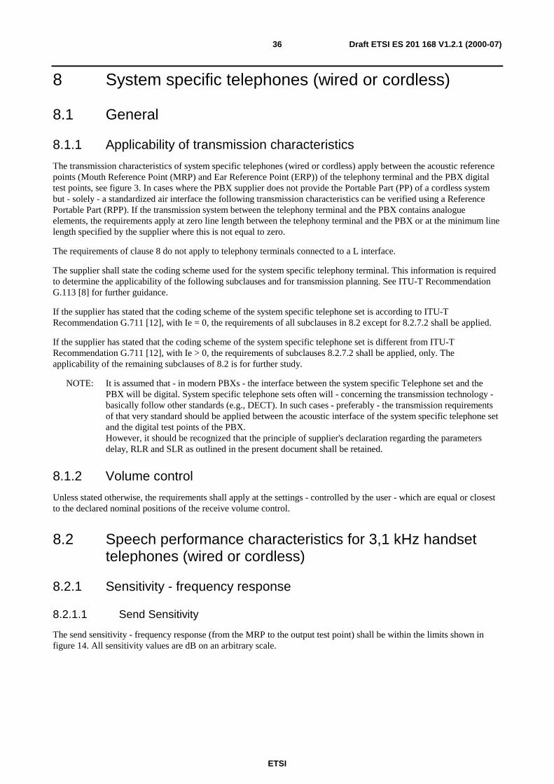
ETSI
Draft ETSI ES 201 168 V1.2.1 (2000-07)36
8 System specific telephones (wired or cordless)
8.1 General
8.1.1 Applicability of transmission characteristics
The transmission characteristics of system specific telephones (wired or cordless) apply between the acoustic referencepoints (Mouth Reference Point (MRP) and Ear Reference Point (ERP)) of the telephony terminal and the PBX digitaltest points, see figure 3. In cases where the PBX supplier does not provide the Portable Part (PP) of a cordless systembut - solely - a standardized air interface the following transmission characteristics can be verified using a ReferencePortable Part (RPP). If the transmission system between the telephony terminal and the PBX contains analogueelements, the requirements apply at zero line length between the telephony terminal and the PBX or at the minimum linelength specified by the supplier where this is not equal to zero.
The requirements of clause 8 do not apply to telephony terminals connected to a L interface.
The supplier shall state the coding scheme used for the system specific telephony terminal. This information is requiredto determine the applicability of the following subclauses and for transmission planning. See ITU-T RecommendationG.113 [8] for further guidance.
If the supplier has stated that the coding scheme of the system specific telephone set is according to ITU-TRecommendation G.711 [12], with Ie = 0, the requirements of all subclauses in 8.2 except for 8.2.7.2 shall be applied.
If the supplier has stated that the coding scheme of the system specific telephone set is different from ITU-TRecommendation G.711 [12], with Ie > 0, the requirements of subclauses 8.2.7.2 shall be applied, only. Theapplicability of the remaining subclauses of 8.2 is for further study.
NOTE: It is assumed that - in modern PBXs - the interface between the system specific Telephone set and thePBX will be digital. System specific telephone sets often will - concerning the transmission technology -basically follow other standards (e.g., DECT). In such cases - preferably - the transmission requirementsof that very standard should be applied between the acoustic interface of the system specific telephone setand the digital test points of the PBX.However, it should be recognized that the principle of supplier's declaration regarding the parametersdelay, RLR and SLR as outlined in the present document shall be retained.
8.1.2 Volume control
Unless stated otherwise, the requirements shall apply at the settings - controlled by the user - which are equal or closestto the declared nominal positions of the receive volume control.
8.2 Speech performance characteristics for 3,1 kHz handsettelephones (wired or cordless)
8.2.1 Sensitivity - frequency response
8.2.1.1 Send Sensitivity
The send sensitivity - frequency response (from the MRP to the output test point) shall be within the limits shown infigure 14. All sensitivity values are dB on an arbitrary scale.
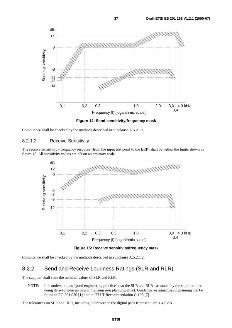
ETSI
Draft ETSI ES 201 168 V1.2.1 (2000-07)37
0
0,1 0,2 0,3 1,0 2,0 3,0 4,0 kHz3,4
-14
-8
+4
dB
-11
Frequency (f) [logarithmic scale]
Sen
ding
sens
itivi
ty
-12
Figure 14: Send sensitivity/frequency mask
Compliance shall be checked by the methods described in subclause A.5.2.1.1.
8.2.1.2 Receive Sensitivity
The receive sensitivity - frequency response (from the input test point to the ERP) shall be within the limits shown infigure 15. All sensitivity values are dB on an arbitrary scale.
0
0,1 0,2 0,3 1,0 3,0 4,0 kHz3,4
-12
dB
Frequency (f) [logarithmic scale]
Rec
eivi
ngse
nsiti
vity
-7
+2
0,5
-9
-6
Figure 15: Receive sensitivity/frequency mask
Compliance shall be checked by the methods described in subclause A.5.2.1.2.
8.2.2 Send and Receive Loudness Ratings (SLR and RLR)
The supplier shall state the nominal values of SLR and RLR.
NOTE: It is understood as "good engineering practice" that the SLR and RLR - as stated by the supplier - arebeing derived from an overall transmission planning effort. Guidance on transmission planning can befound in EG 201 050 [1] and in ITU-T Recommendation G.108 [7].
The tolerances on SLR and RLR, including tolerances in the digital pads if present, are ± 4,0 dB.
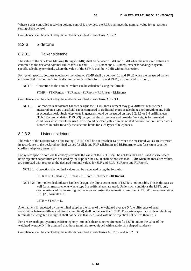
ETSI
Draft ETSI ES 201 168 V1.2.1 (2000-07)38
Where a user-controlled receiving volume control is provided, the RLR shall meet the nominal value for at least onesetting of the control.
Compliance shall be checked by the methods described in subclause A.5.2.2.
8.2.3 Sidetone
8.2.3.1 Talker sidetone
The value of the SideTone Masking Rating (STMR) shall be between 13 dB and 18 dB when the measured values arecorrected to the declared nominal values for SLR and RLR (SLRnom and RLRnom), except for analogue systemspecific telephony terminals, where the value of the STMR shall be > 7 dB without correction.
For system specific cordless telephones the value of STMR shall be between 10 and 18 dB when the measured valuesare corrected in accordance to the declared nominal values for SLR and RLR (SLRnom and RLRnom).
NOTE: Correction to the nominal values can be calculated using the formula:
STMR = STMRmeas - (SLRmeas - SLRnom + RLRmeas - RLRnom).
Compliance shall be checked by the methods described in subclause A.5.2.3.1.
NOTE: For modern leak tolerant handset designs the STMR measurement may give different results whenmeasured on a type 1 artificial ear as compared to traditional types of telephones not providing any builtin acoustical leak. Such telephones in general should be measured on type 3.2, 3.3 or 3.4 artificial ears.ITU-T Recommendation P.79 [29] recognizes the differences and provides W-weights for unsealedconditions which should be used. This should be clearly stated in the related documentation. Further workis needed in order to verify the sidetone limits for such types of telephones.
8.2.3.2 Listener sidetone
The value of the Listener Side Tone Rating (LSTR) shall be not less than 13 dB when the measured values are correctedin accordance to the declared nominal values for SLR and RLR (SLRnom and RLRnom), except for system specificcordless telephony terminals.
For system specific cordless telephony terminals the value of the LSTR shall be not less than 10 dB and in case wherenoise rejection capabilities are declared by the supplier the LSTR shall be not less than 15 dB when the measured valuesare corrected with respect to the declared nominal values for SLR and RLR (SLRnom and RLRnom).
NOTE 1: Correction the nominal values can be calculated using the formula:
LSTR = LSTRmeas - (SLRmeas - SLRnom + RLRmeas - RLRnom).
NOTE 2: For modern leak tolerant handset designs the direct assessment of LSTR is not possible. This is the case aswell for all measurements where type 3.x artificial ears are used. Under such conditions the LSTR onlycan be estimated by measuring the D-factor and using the estimation described in ITU-T RecommendationP.79 [29] formula E.1:
LSTR = STMR + D.
Alternatively if requested by the terminal supplier the value of the weighted average D (the difference of sendsensitivities between diffuse and direct sound field) shall not be less than +2 dB. For system specific cordless telephonyterminals the weighted average D shall not be less than -5 dB and with noise rejection not be less than 0 dB.
For 2-wire analogue system specific telephony terminals there is no requirement for LSTR and/or the value of theweighted average D (it is assumed that those terminals are equipped with traditionally shaped handsets).
Compliance shall be checked by the methods described in subclauses A.5.2.3.2 and A.5.2.3.3.
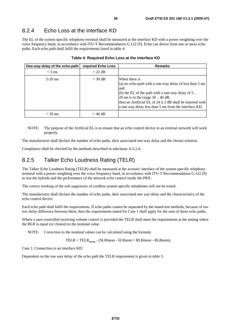
ETSI
Draft ETSI ES 201 168 V1.2.1 (2000-07)39
8.2.4 Echo Loss at the interface KD
The EL of the system specific telephony terminal shall be measured at the interface KD with a power weighting over thevoice frequency band, in accordance with ITU-T Recommendation G.122 [9]. Echo can derive from one or more echopaths. Each echo path shall fulfil the requirements listed in table 4:
Table 4: Required Echo Loss at the interface KD
One-way delay of the echo-path required Echo Loss Remarks
< 5 ms > 22 dB
5-20 ms > 30 dB When there is(a) no echo-path with a one-way delay of less than 5 msand(b) the EL of the path with a one-way delay of 5 ..20 ms is in the range 30 .. 46 dB,then an Artificial EL of 24 ± 2 dB shall be inserted witha one way delay less than 5 ms from the interface KD.
> 20 ms > 46 dB
NOTE: The purpose of the Artificial EL is to ensure that an echo control device in an external network will workproperly.
The manufacturer shall declare the number of echo paths, their associated one-way delay and the chosen solution.
Compliance shall be checked by the methods described in subclause A.5.2.4.
8.2.5 Talker Echo Loudness Rating (TELR)
The Talker Echo Loudness Rating (TELR) shall be measured at the acoustic interface of the system specific telephonyterminal with a power weighting over the voice frequency band, in accordance with ITU-T Recommendation G.122 [9]to test the hybrids and the performance of the network echo control inside the PBX.
The correct working of the soft suppressor of cordless system specific telephones will not be tested.
The manufacturer shall declare the number of echo paths, their associated one way delay and the characteristics of theecho control device.
Each echo path shall fulfil the requirements. If echo paths cannot be separated by the stated test methods, because of toolow delay difference between them, then the requirements stated for Case 1 shall apply for the sum of those echo paths.
Where a user-controlled receiving volume control is provided the TELR shall meet the requirements at the setting wherethe RLR is equal (or closest) to the nominal value.
NOTE: Correction to the nominal values can be calculated using the formula:
TELR = TELRmeas - (SLRmeas - SLRnom + RLRmeas - RLRnom).
Case 1: Connection to an interface KD:
Dependent on the one way delay of the echo path the TELR requirement is given in table 5.
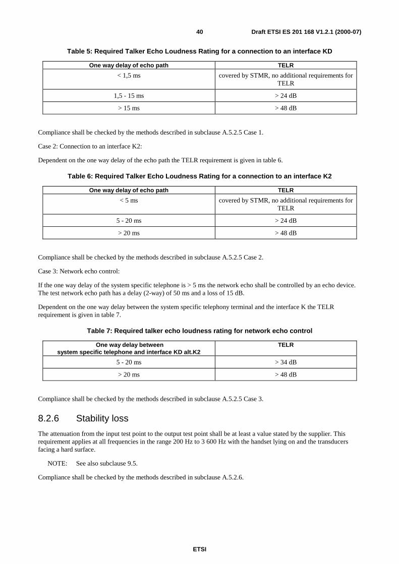
ETSI
Draft ETSI ES 201 168 V1.2.1 (2000-07)40
Table 5: Required Talker Echo Loudness Rating for a connection to an interface KD
One way delay of echo path TELR
< 1,5 ms covered by STMR, no additional requirements forTELR
1,5 - 15 ms > 24 dB
> 15 ms > 48 dB
Compliance shall be checked by the methods described in subclause A.5.2.5 Case 1.
Case 2: Connection to an interface K2:
Dependent on the one way delay of the echo path the TELR requirement is given in table 6.
Table 6: Required Talker Echo Loudness Rating for a connection to an interface K2
One way delay of echo path TELR
< 5 ms covered by STMR, no additional requirements forTELR
5 - 20 ms > 24 dB
> 20 ms > 48 dB
Compliance shall be checked by the methods described in subclause A.5.2.5 Case 2.
Case 3: Network echo control:
If the one way delay of the system specific telephone is > 5 ms the network echo shall be controlled by an echo device.The test network echo path has a delay (2-way) of 50 ms and a loss of 15 dB.
Dependent on the one way delay between the system specific telephony terminal and the interface K the TELRrequirement is given in table 7.
Table 7: Required talker echo loudness rating for network echo control
One way delay betweensystem specific telephone and interface KD alt.K2
TELR
5 - 20 ms > 34 dB
> 20 ms > 48 dB
Compliance shall be checked by the methods described in subclause A.5.2.5 Case 3.
8.2.6 Stability loss
The attenuation from the input test point to the output test point shall be at least a value stated by the supplier. Thisrequirement applies at all frequencies in the range 200 Hz to 3 600 Hz with the handset lying on and the transducersfacing a hard surface.
NOTE: See also subclause 9.5.
Compliance shall be checked by the methods described in subclause A.5.2.6.

ETSI
Draft ETSI ES 201 168 V1.2.1 (2000-07)41
8.2.7 Transmission impairments
8.2.7.1 Total Distortion, including Quantizing Distortion
The requirements in this subclause are only applicable if the supplier has stated the coding scheme to be in accordancewith ITU-T Recommendation G.711 [12] and if the Equipment Impairment Factor, Ie = 0.
8.2.7.1.1 Sending
The system specific telephony terminal shall meet the requirements of one of the subclauses 8.2.7.1.1.1 or 8.2.7.1.1.2.
8.2.7.1.1.1 Method 1 (Pseudo random noise stimulus)
The test signal shall consist of a band-limited noise signal conforming to ITU-T Recommendation O.131 [20]. The ratioof signal-to-total distortion (harmonic and quantizing) power of the digitally encoded signal output by the systemspecific telephony terminal shall lie above the limits shown in figure 16 unless the sound pressure at the MRP is greaterthan +5 dBPa.
Compliance shall be checked by the methods described in subclause A.5.2.7.1.1.
8.2.7.1.1.2 Method 2 (Sinewave test signal)
The test signal shall be a sine-wave with a frequency in the range 1 004 Hz to 1 025 Hz. The ratio of signal-to-totaldistortion (harmonic and quantizing) power of the digitally encoded signal output by the system specific telephonyterminal, when passing through a noise weighting as specified in table 4 of ITU-T Recommendation G.223 [10], shall lieabove the limits shown in figure 17 unless the sound pressure at the MRP is greater than +10 dBPa.
Compliance shall be checked by the methods described in subclause A.5.2.7.1.2.
8.2.7.1.2 Receiving
The system specific telephony terminal shall meet the requirements of one of the subclauses 8.2.7.1.2.1 or 8.2.7.1.2.2.
8.2.7.1.2.1 Method 1 (Pseudo random noise stimulus)
The test signal shall consist of a band-limited noise signal conforming to ITU-T Recommendation O.131 [20]. The ratioof signal-to-total distortion (harmonic and quantizing) power of the signal in the artificial ear shall lie above the limitsshown in figure 18 unless the signal in the artificial ear is greater than +5 dBPa or is less than -50 dBPa.
Compliance shall be checked by the methods described in subclause A.5.2.7.2.1.
8.2.7.1.2.2 Method 2 (Sinewave test signal)
The test signal shall be a sine-wave with a frequency in the range 1 004 Hz to 1 025 Hz. The ratio of signal-to-totaldistortion (harmonic and quantizing) power of the signal in the artificial ear, when passing through a noise weighting asspecified in table 4 of ITU-T Recommendation G.223 [10], shall lie above the limits shown in figure 19 unless the signalin the artificial ear is greater than +10 dBPa or is less than -50 dBPa.
Compliance shall be checked by the methods described in subclause A.5.2.7.2.2.
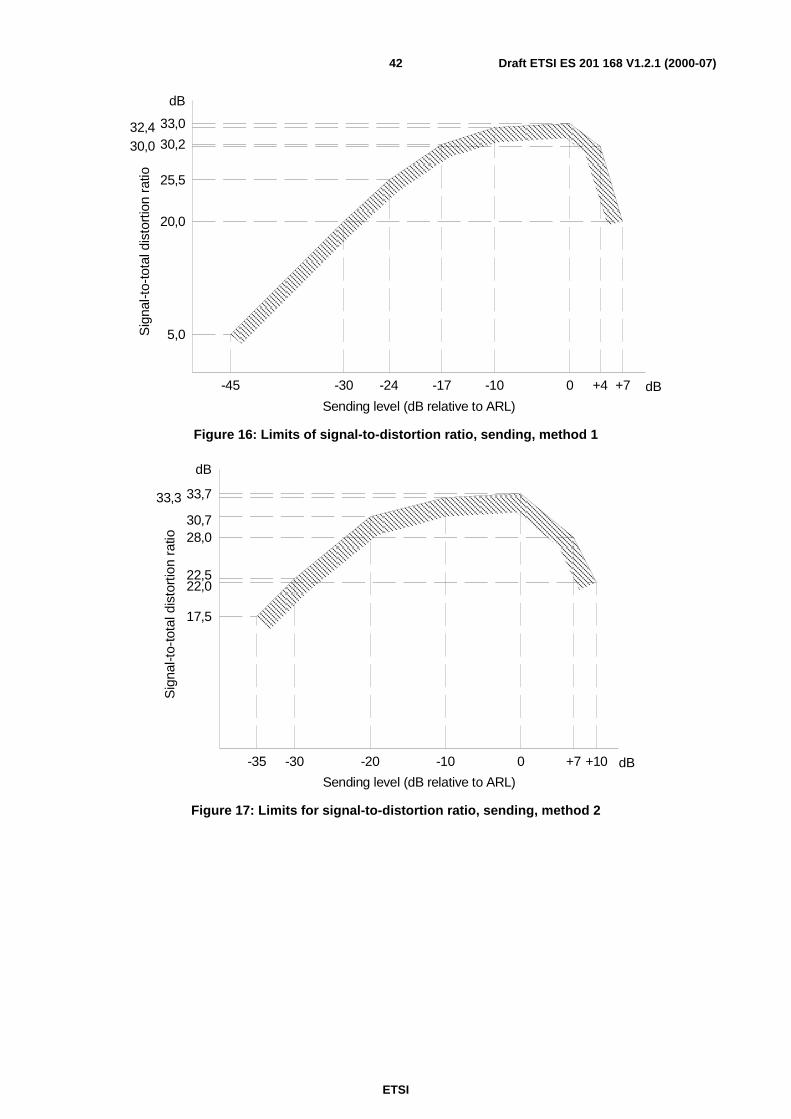
ETSI
Draft ETSI ES 201 168 V1.2.1 (2000-07)42
5,0
20,0
25,5
30,232,4 33,0
dB
-45 -30 -24 -17 -10 0 +4 +7
Sig
nal-t
o-to
tald
isto
rtio
nra
tio
Sending level (dB relative to ARL)
dB
30,0
Figure 16: Limits of signal-to-distortion ratio, sending, method 1
30,7
33,733,3
22,5
17,5
-35 -30 -20 -10 0 +7 +10 dB
dB
Sending level (dB relative to ARL)
Sig
nal-t
o-to
tald
isto
rtio
nra
tio
22,0
28,0
Figure 17: Limits for signal-to-distortion ratio, sending, method 2
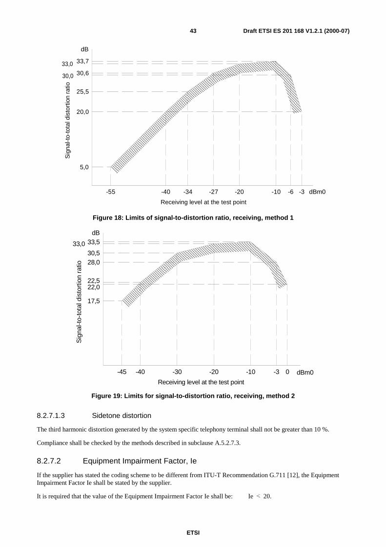
ETSI
Draft ETSI ES 201 168 V1.2.1 (2000-07)43
33,0 33,7
30,6
25,5
20,0
5,0
-55 -40 -34 -27 -20 -10 -6 -3
Receiving level at the test point
Sig
nal-t
o-to
tald
isto
rtio
nra
tio
dB
dBm0
30,0
Figure 18: Limits of signal-to-distortion ratio, receiving, method 1
17,5
22,5
30,5
33,533,0
dB
-45 -40 -30 -20 -10 -3 0 dBm0
Receiving level at the test point
Sig
nal-t
o-to
tald
isto
rtio
nra
tio
22,0
28,0
Figure 19: Limits for signal-to-distortion ratio, receiving, method 2
8.2.7.1.3 Sidetone distortion
The third harmonic distortion generated by the system specific telephony terminal shall not be greater than 10 %.
Compliance shall be checked by the methods described in subclause A.5.2.7.3.
8.2.7.2 Equipment Impairment Factor, Ie
If the supplier has stated the coding scheme to be different from ITU-T Recommendation G.711 [12], the EquipmentImpairment Factor Ie shall be stated by the supplier.
It is required that the value of the Equipment Impairment Factor Ie shall be: Ie ≤ 20.
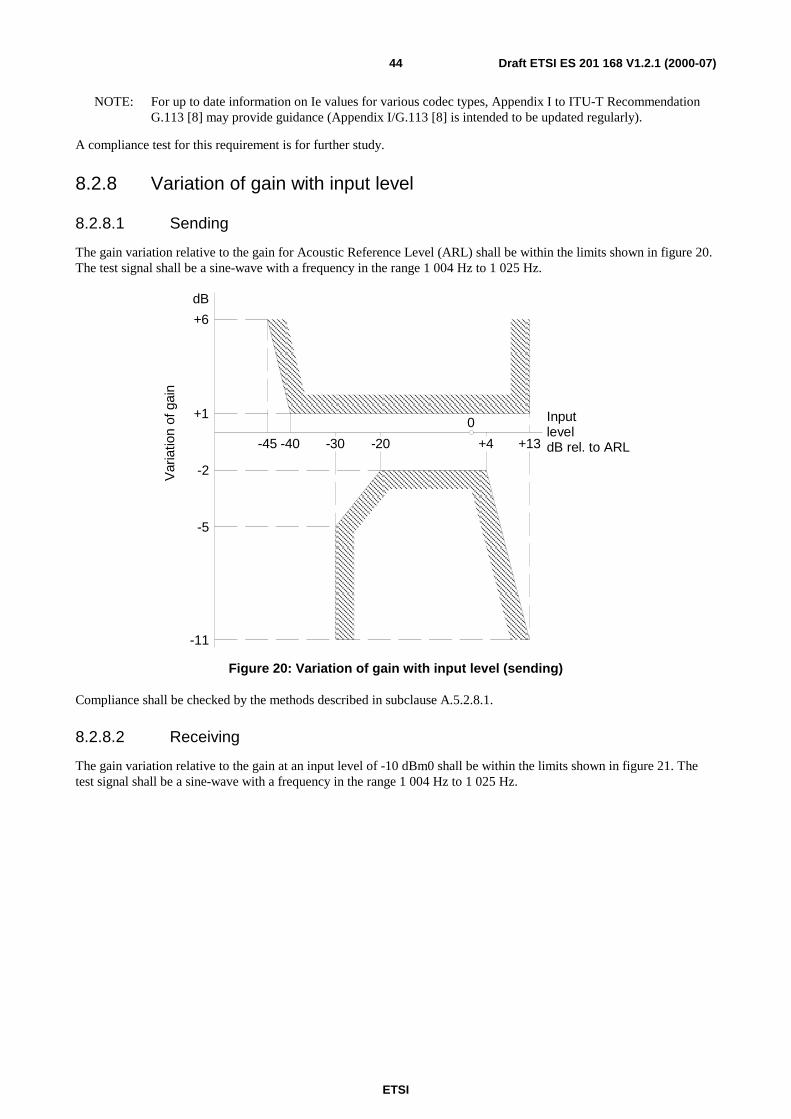
ETSI
Draft ETSI ES 201 168 V1.2.1 (2000-07)44
NOTE: For up to date information on Ie values for various codec types, Appendix I to ITU-T RecommendationG.113 [8] may provide guidance (Appendix I/G.113 [8] is intended to be updated regularly).
A compliance test for this requirement is for further study.
8.2.8 Variation of gain with input level
8.2.8.1 Sending
The gain variation relative to the gain for Acoustic Reference Level (ARL) shall be within the limits shown in figure 20.The test signal shall be a sine-wave with a frequency in the range 1 004 Hz to 1 025 Hz.
+13
0
-30-40
InputleveldB rel. to ARL
-2
dB
Var
iatio
nof
gain
-45 +4-20
-5
-11
+1
+6
Figure 20: Variation of gain with input level (sending)
Compliance shall be checked by the methods described in subclause A.5.2.8.1.
8.2.8.2 Receiving
The gain variation relative to the gain at an input level of -10 dBm0 shall be within the limits shown in figure 21. Thetest signal shall be a sine-wave with a frequency in the range 1 004 Hz to 1 025 Hz.
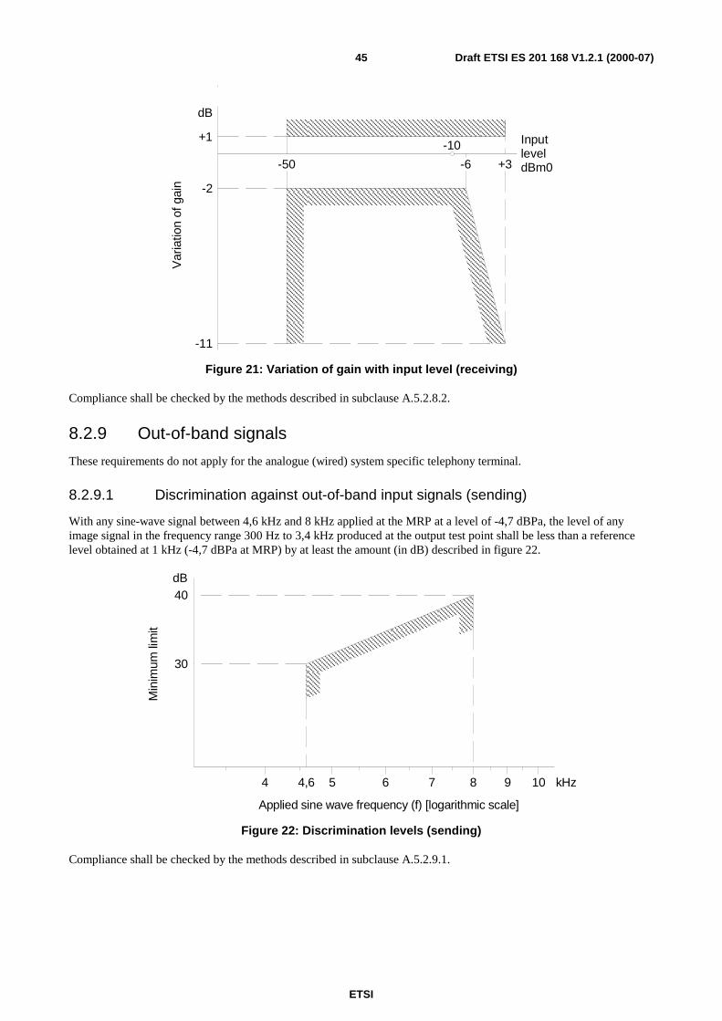
ETSI
Draft ETSI ES 201 168 V1.2.1 (2000-07)45
+3-6-50
InputleveldBm0
-2
+1
dB
Var
iatio
nof
gain
-10
-11
Figure 21: Variation of gain with input level (receiving)
Compliance shall be checked by the methods described in subclause A.5.2.8.2.
8.2.9 Out-of-band signals
These requirements do not apply for the analogue (wired) system specific telephony terminal.
8.2.9.1 Discrimination against out-of-band input signals (sending)
With any sine-wave signal between 4,6 kHz and 8 kHz applied at the MRP at a level of -4,7 dBPa, the level of anyimage signal in the frequency range 300 Hz to 3,4 kHz produced at the output test point shall be less than a referencelevel obtained at 1 kHz (-4,7 dBPa at MRP) by at least the amount (in dB) described in figure 22.
40
30
dB
Min
imum
limit
4 54,6 6 7 8 9 10 kHz
Applied sine wave frequency (f) [logarithmic scale]
Figure 22: Discrimination levels (sending)
Compliance shall be checked by the methods described in subclause A.5.2.9.1.
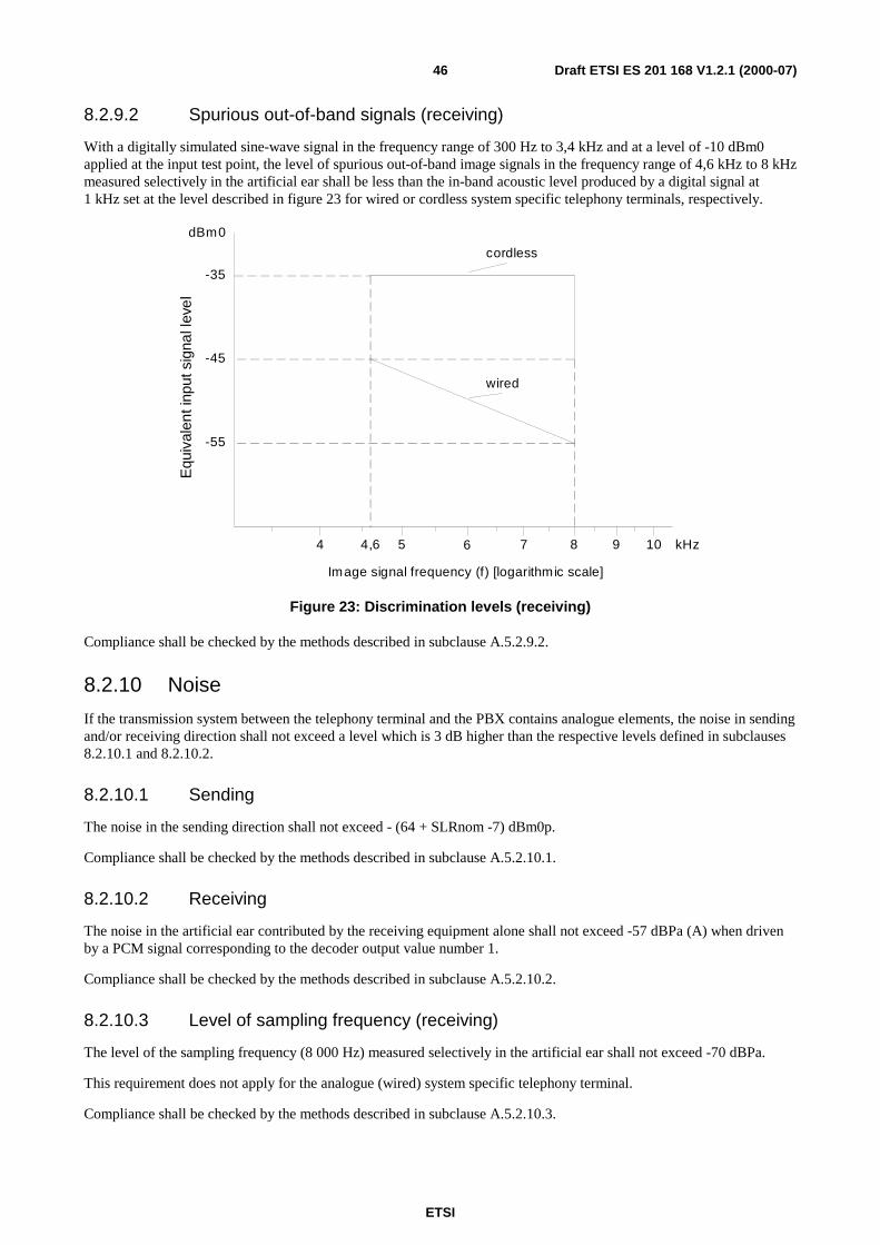
ETSI
Draft ETSI ES 201 168 V1.2.1 (2000-07)46
8.2.9.2 Spurious out-of-band signals (receiving)
With a digitally simulated sine-wave signal in the frequency range of 300 Hz to 3,4 kHz and at a level of -10 dBm0applied at the input test point, the level of spurious out-of-band image signals in the frequency range of 4,6 kHz to 8 kHzmeasured selectively in the artificial ear shall be less than the in-band acoustic level produced by a digital signal at1 kHz set at the level described in figure 23 for wired or cordless system specific telephony terminals, respectively.
4 4,6 5 7 8 9 10 kHz6
Image signal frequency (f) [logarithmic scale]
-45
-55
dBm0
-35
wired
cordless
Equ
ival
enti
nput
sign
alle
vel
Figure 23: Discrimination levels (receiving)
Compliance shall be checked by the methods described in subclause A.5.2.9.2.
8.2.10 Noise
If the transmission system between the telephony terminal and the PBX contains analogue elements, the noise in sendingand/or receiving direction shall not exceed a level which is 3 dB higher than the respective levels defined in subclauses8.2.10.1 and 8.2.10.2.
8.2.10.1 Sending
The noise in the sending direction shall not exceed - (64 + SLRnom -7) dBm0p.
Compliance shall be checked by the methods described in subclause A.5.2.10.1.
8.2.10.2 Receiving
The noise in the artificial ear contributed by the receiving equipment alone shall not exceed -57 dBPa (A) when drivenby a PCM signal corresponding to the decoder output value number 1.
Compliance shall be checked by the methods described in subclause A.5.2.10.2.
8.2.10.3 Level of sampling frequency (receiving)
The level of the sampling frequency (8 000 Hz) measured selectively in the artificial ear shall not exceed -70 dBPa.
This requirement does not apply for the analogue (wired) system specific telephony terminal.
Compliance shall be checked by the methods described in subclause A.5.2.10.3.
ETSI
Draft ETSI ES 201 168 V1.2.1 (2000-07)47
9 Characteristics for connections between twointerfaces
9.1 GeneralInformation about performance when interconnecting two interfaces applies only where this interconnection is intended,and when the interfaces are interconnected via the switch matrix. These interfaces can be electrical or acousticinterfaces.
NOTE: The information in this clause is mainly for the benefit of transmission planners.
9.2 Transmission loss between interfacesThe value of transmission loss between interfaces shall be stated by the supplier.
NOTE: In the case of system specific telephony terminals this includes also the values for SLR and RLR.
9.3 Quantizing distortion units (qdu)For codecs complying to ITU-T Recommendation G.711 [12] , the number of qdu should be stated by the supplier.
NOTE 1: The parameter qdu applies not only to A/D-D/A conversions but also to other processes influencing thedigital bit-stream. Those processes are, for example, the insertion of digital loss or gain, signal addition inconference circuits, use of digital echo cancellers, etc. For coding laws other than A-law/µ-law (e.g.according to ITU-T Recommendations G.726 [14], G.727 [15] or G.728 [16]), the parameter qdu hasbeen replaced by the Equipment Impairment Factor, Ie (see subclause 9.4). See ITU-T RecommendationG.113 [8] for further guidance.
NOTE 2: The number of qdu is 1 between two analogue interfaces if no digital loss pad is introduced in theconnection, or if the digital pad has a value equal to 6 dB (20*log(2) = 6,02 dB).
9.4 Equipment Impairment Factor, IeIf the supplier has stated the coding scheme to be different from ITU-T Recommendation G.711 [12], the EquipmentImpairment Factor Ie shall be stated by the supplier.
It is required that the value of the Equipment Impairment Factor Ie shall be: Ie ≤ 20.
NOTE: For up to date information on Ie values for various codec types, Appendix I to ITU-T RecommendationG.113 [8] may provide guidance (Appendix I/G.113 [8] is intended to be updated regularly).
A compliance test for this requirement is for further study.
9.5 Mean one-way transmission timeThe mean one way transmission time in a connection between two interfaces including the acoustic interfaces of systemspecific telephones shall be a value stated by the supplier.
ETSI
Draft ETSI ES 201 168 V1.2.1 (2000-07)48
9.6 Stability loss
9.6.1 Stability loss of interfaces connected to a KD interface
The nominal stability loss of connections to a KD interface shall be at least 6 dB at all frequencies in the range 200 Hzto 3 600 Hz, when measured from the input of the KD interface to the output of the KD interface. However, where thenational transmission plan ensures that extra loss is added in the public network for international calls, the stability lossvalue in this clause shall be reduced by the value of such extra loss.
Termination of 2-wire interfaces connected to KD shall be as specified in subclause 5.8.2. Termination of a systemspecific telephony terminal interface connected to KD shall be as specified in subclause 8.2.5.
9.6.2 Stability loss of interfaces connected to M4, MD or MS interfaces
The nominal stability loss of connections to M4, MD or MS interfaces shall be at least 6 dB at all frequencies in therange 200 Hz to 3 600 Hz, when measured from the input of the M4, MD or MS interface to the output of the M4, MDor MS interface. Termination of 2-wire interfaces connected to M4, MD or MS shall be as specified in subclause 5.8.2.Termination of a system specific telephony terminal interface connected to M4, MD or MS shall be as specified insubclause 8.2.5.
Where the PBX is connected to transmission equipment there may be a need to adjust the relative levels of the M4interface to such values that the stability loss of the PBX in question is less than 6 dB.
NOTE: In these cases the loss in the transmission system will ensure that the 6 dB stability margin is still met.
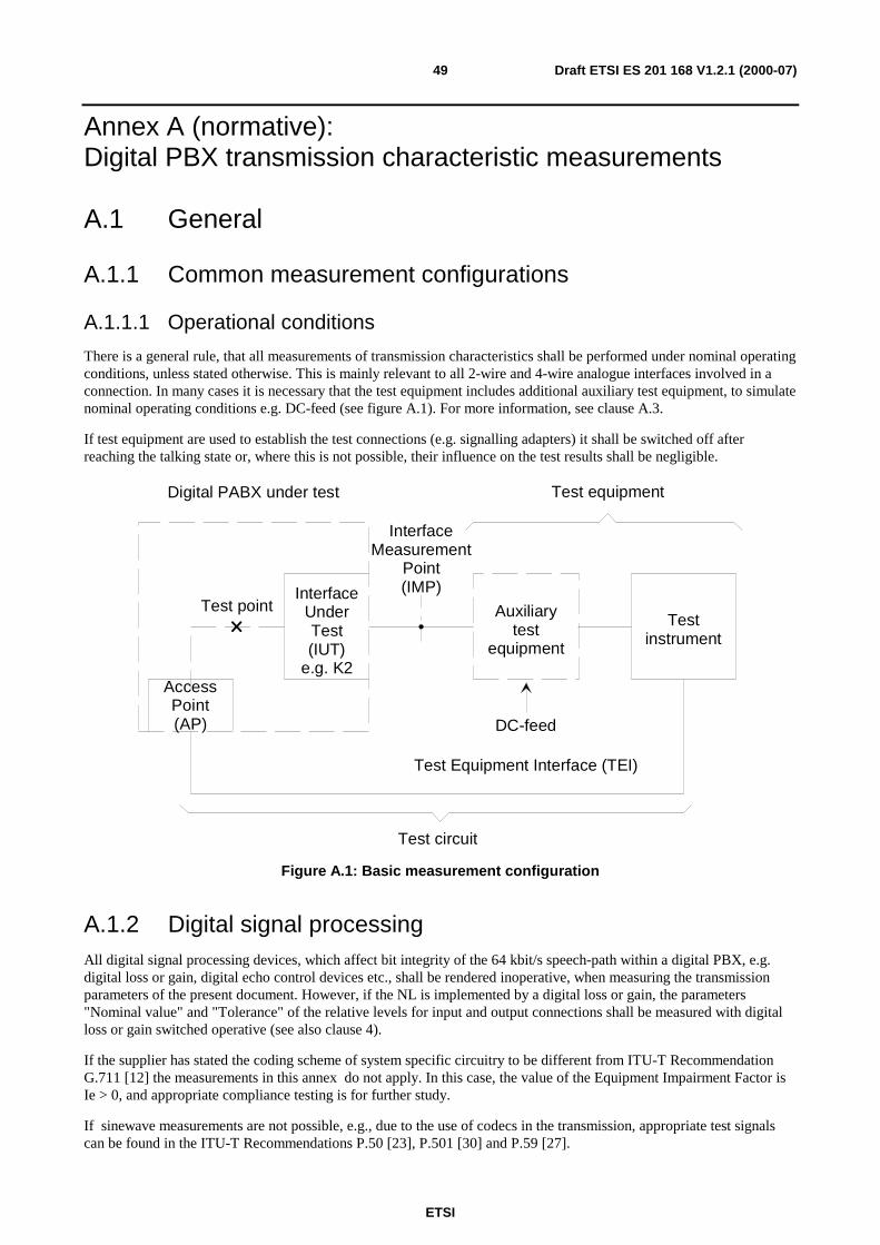
ETSI
Draft ETSI ES 201 168 V1.2.1 (2000-07)49
Annex A (normative):Digital PBX transmission characteristic measurements
A.1 General
A.1.1 Common measurement configurations
A.1.1.1 Operational conditions
There is a general rule, that all measurements of transmission characteristics shall be performed under nominal operatingconditions, unless stated otherwise. This is mainly relevant to all 2-wire and 4-wire analogue interfaces involved in aconnection. In many cases it is necessary that the test equipment includes additional auxiliary test equipment, to simulatenominal operating conditions e.g. DC-feed (see figure A.1). For more information, see clause A.3.
If test equipment are used to establish the test connections (e.g. signalling adapters) it shall be switched off afterreaching the talking state or, where this is not possible, their influence on the test results shall be negligible.
Digital PABX under test
InterfaceUnderTest(IUT)
e.g. K2AccessPoint(AP)
Test point
InterfaceMeasurement
Point(IMP)
Auxiliarytest
equipment
Testinstrument
Test circuit
Test equipment
DC-feed
Test Equipment Interface (TEI)
Figure A.1: Basic measurement configuration
A.1.2 Digital signal processingAll digital signal processing devices, which affect bit integrity of the 64 kbit/s speech-path within a digital PBX, e.g.digital loss or gain, digital echo control devices etc., shall be rendered inoperative, when measuring the transmissionparameters of the present document. However, if the NL is implemented by a digital loss or gain, the parameters"Nominal value" and "Tolerance" of the relative levels for input and output connections shall be measured with digitalloss or gain switched operative (see also clause 4).
If the supplier has stated the coding scheme of system specific circuitry to be different from ITU-T RecommendationG.711 [12] the measurements in this annex do not apply. In this case, the value of the Equipment Impairment Factor isIe > 0, and appropriate compliance testing is for further study.
If sinewave measurements are not possible, e.g., due to the use of codecs in the transmission, appropriate test signalscan be found in the ITU-T Recommendations P.50 [23], P.501 [30] and P.59 [27].
ETSI
Draft ETSI ES 201 168 V1.2.1 (2000-07)50
A.1.3 Reference frequencyThe reference frequency shall be 1 020 Hz for test frequency generating circuits or instruments, that provide referencetest frequencies. The specified frequency tolerance shall be +2 Hz to -7 Hz.
A.1.4 ImpedanceUnless otherwise specified, measurements at analogue interfaces shall be made under matched conditions to the nominalimpedance Zr of the Interface Under Test (IUT). The interpretation of this statement is, that the nominal PBXimpedance is used as the internal impedance of the test signal generator and the analogue level meter, i.e. testinstruments with integrated test impedances.
NOTE: For more flexibility it may be preferable to use a low-impedance generator and a high-impedance meter inconjunction with a suitable external test impedance, which corresponds to an exact matching to thenominal PBX impedance.
A.1.5 Measurement pointsAs far as analogue 2-wire or 4-wire interfaces are considered, the Interface Measurement Point (IMP) shall be at the firstpoint of isolation as indicated by the PBX supplier, which provides testing access to the PBX and all external cabling.This means, that all cabling between this point and the interface card in the system, are included in the test results.
NOTE: For the test point used in conjunction with input/output-measurements and its access, see subclause 3.1.2.
A.1.6 Test InstrumentsFor the choice of test instruments the following features shall be considered:
The test instrumentation consists of the following four functional units:
- an analogue signal generator A to apply test signals to the IMP of the PBX under test e.g. via an auxiliary testequipment (see also subclause A.1.5 and clause A.3). For more information, see subclause 3.2 of ITU-TRecommendation O.133 [22];
- an analogue signal analyser B to process received signals from the IMP of the PBX under test e.g. via anauxiliary test equipment (see also subclause A.1.5 and clause A.3). For more information, see subclause 3.3 ofITU-T Recommendation O.133 [22];
- a digital signal generator C to apply test-signals to the Access Point (AP) or the Test Equipment Interface (TEI)of the PBX under test (see also clause A.2). For more information, see subclause 3.4 of ITU-TRecommendation O.133 [22];
- a digital signal analyser D to process signals received from the AP or the TEI of the PBX under test (see alsoclause A.2). For more information, see subclause 3.5 of ITU-T Recommendation O.133 [22].
As a general objective the accuracy of the test instruments shall be an order of magnitude better than the relevantperformance limits of the PBX under test.
In some cases it may not be possible to meet this objective due to technical and cost limitations.
For guidance to the capability and the accuracy of the test instrumentation refer to annex B.
ETSI
Draft ETSI ES 201 168 V1.2.1 (2000-07)51
A.1.7 Test levelsAt the reference frequency, test levels at analogue interfaces are defined in terms of apparent power relative to 1 mW.
Where no value is given, the test level shall be -10 dBm0. However, test levels may be restricted to a maximum absoluteinput and output power level as stated by the supplier.
At frequencies different from the reference frequency, test levels are defined as having the same voltage as the test levelat the reference frequency. Measurements are based on the use of a test generator with a frequency independent electromotive force (emf).
A.1.8 Disturbing effectsWhere the digital input of the test point is not used, a quiet code shall be applied.
Measurements, which involve low output signal levels, or when measuring individual spectral components of a signal,shall be performed using frequency selective equipment. A bandwidth of 80 Hz is recommended.
A.1.9 Alternative test methodsLaboratories may use other test methods provided they are equivalent to those specified in the present document.
Where the supplier requests other test methods as described in this annex the supplier shall provide sufficientinformation about how to perform such tests.
A.2 Test point and access to the test point
A.2.1 Basic principleIn the present document, most of the parameters specified are for input half connections and output half connections. Inthese cases the parameters are referred to a "test point" as given in subclause 3.1.2.1 and figure 3. However, this is onlya virtual point for specification purposes and might be considered as a "reference point".
For measurements, one or more specific AP shall be available to provide a suitable "path" between the test instrumentand the test point. In this path, a part, or all of the switching network will be included. To ensure, that the influence onthe results of this path is negligible, bit integrity is required.
NOTE: This physical access to the test point might be advantageous also for maintenance purposes. However,there is no obligation to provide AP on production systems in the field.
A.2.2 Physical nature of test accessFor measurement purposes, an AP shall be digital in its nature. To avoid additional adaptation equipment between APand test instrument, the following interface types shall be used with the test access:
- 64 kbit/s co-directional, according to clause 1 of ITU-T Recommendation G.703 [11];
- 2 048 kbit/s, according to clause 6 of ITU-T Recommendation G.703 [11];
- 192 kbit/s, according to ITU-T Recommendation I.430 [17].
The synchronization of the test instrument from the digital PBX under test shall be ensured.
The coding law of the test point shall be either A-law or µ-law according to ITU-T Recommendation G.711 [12].
NOTE: A-law is preferred.
ETSI
Draft ETSI ES 201 168 V1.2.1 (2000-07)52
A.2.3 Set-up of test connectionsMeasurements of half connections are normally performed such that a complete bi-directional connection between theAP, via the test point (switching matrix) and the IUT is established.
The responsibility for the following measurement arrangements lies with the supplier:
• it shall be possible to measure all specified input and output parameters as given in the present document;
• this applies for all types of interfaces provided by the PBX such as K, L and M;
• as far as modifications of PBX configurations have an impact on the transmission parameters, each modifiedconfiguration shall be available for compliance testing.
A.3 Auxiliary test equipment
A.3.1 GeneralAs already mentioned in subclause A.1.1.2, measurements shall be performed as far as possible under nominal operatingconditions. For this purpose, test feeding bridges in conjunction with a separate DC power supply and hold circuits areused at analogue interfaces, not only to keep the measured connection in the talking state, but also to provide a DCflowing, since the transmission characteristics of interfaces may vary with DC.
Furthermore, some modern test instruments (see subclause A.1.6) may only consist of an analogue or digital signalgenerator and signal receiver, but may not include additional bridge circuits as necessary, e.g. for return lossmeasurements. In those cases, external equipment shall be used in conjunction with the main PCM test instrument.Where artificial cables are included in the test circuit their characteristics shall be defined and standardized.
Every auxiliary test equipment which is part of the test circuit, shall have negligible influence on the test results.
NOTE: The values of inductances and capacitances used in auxiliary test equipment, may be sufficient formeasurements with nominal input or test impedances of 600Ω resistive, but not for all capacitive compleximpedances.
Considering all these facts, the following subclauses will give minimum requirements for all important auxiliary testequipment, to ensure, that their influence on the test results is negligible.
A.3.2 DC power supplyIf DC power supply units are used in conjunction with a feeding bridge as part of the test circuit, any superimposednoise voltage shall have negligible influence on the test results. More information is given in the relevant subclauses ofclause A.4.
A.3.3 Transmission Decoupling Unit (TDU)A TDU is used to either feed a DC into the appropriate analogue 2-wire or 4-wire point of the system under test, or toprovide a DC loop. Where these assumptions do not apply there is no need to insert a TDU.
The basic circuit of a TDU is shown in figure A.2. The realization shall provide also a negligible influence when used incommon mode configuration as necessary for impedance unbalance measurements, in conjunction with DC powersupply which is connected to ground.
If TDUs with active elements are used, linearity over the full range of test signal level and the respective noiseperformance shall be taken into account.
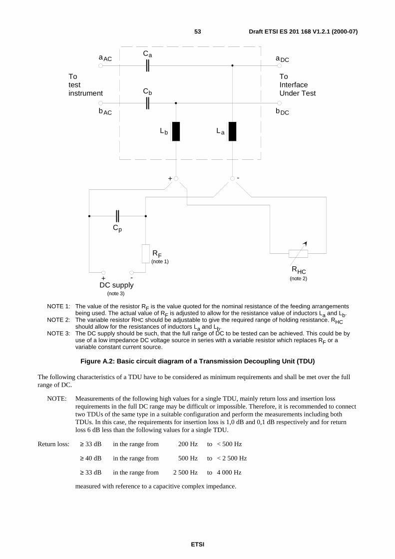
ETSI
Draft ETSI ES 201 168 V1.2.1 (2000-07)53
aAC
bAC bDC
DCaCa
Cb
Lb La
Cp
RF(note 1)
RHC(note 2)+ -
DC supply(note 3)
ToInterfaceUnder Test
Totestinstrument
+ -
NOTE 1: The value of the resistor RF is the value quoted for the nominal resistance of the feeding arrangementsbeing used. The actual value of RF is adjusted to allow for the resistance value of inductors La and Lb.
NOTE 2: The variable resistor RHC should be adjustable to give the required range of holding resistance. RHCshould allow for the resistances of inductors La and Lb.
NOTE 3: The DC supply should be such, that the full range of DC to be tested can be achieved. This could be byuse of a low impedance DC voltage source in series with a variable resistor which replaces RF or avariable constant current source.
Figure A.2: Basic circuit diagram of a Transmission Decoupling Unit (TDU)
The following characteristics of a TDU have to be considered as minimum requirements and shall be met over the fullrange of DC.
NOTE: Measurements of the following high values for a single TDU, mainly return loss and insertion lossrequirements in the full DC range may be difficult or impossible. Therefore, it is recommended to connecttwo TDUs of the same type in a suitable configuration and perform the measurements including bothTDUs. In this case, the requirements for insertion loss is 1,0 dB and 0,1 dB respectively and for returnloss 6 dB less than the following values for a single TDU.
Return loss: ≥ 33 dB in the range from 200 Hz to < 500 Hz
≥ 40 dB in the range from 500 Hz to < 2 500 Hz
≥ 33 dB in the range from 2 500 Hz to 4 000 Hz
measured with reference to a capacitive complex impedance.
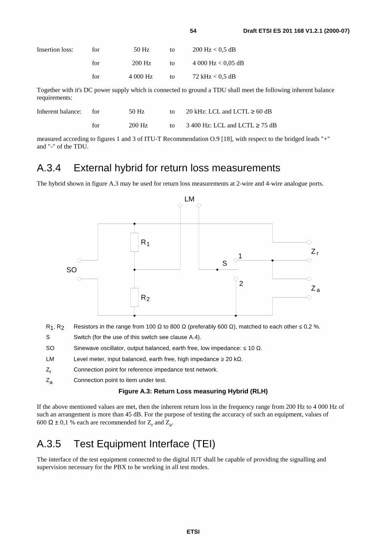
ETSI
Draft ETSI ES 201 168 V1.2.1 (2000-07)54
Insertion loss: for 50 Hz to 200 Hz < 0,5 dB
for 200 Hz to 4 000 Hz < 0,05 dB
for 4 000 Hz to 72 kHz < 0,5 dB
Together with it's DC power supply which is connected to ground a TDU shall meet the following inherent balancerequirements:
Inherent balance: for 50 Hz to 20 kHz: LCL and LCTL ≥ 60 dB
for 200 Hz to 3 400 Hz: LCL and LCTL ≥ 75 dB
measured according to figures 1 and 3 of ITU-T Recommendation O.9 [18], with respect to the bridged leads "+"and "-" of the TDU.
A.3.4 External hybrid for return loss measurementsThe hybrid shown in figure A.3 may be used for return loss measurements at 2-wire and 4-wire analogue ports.
S1
2
LM
R1
R2
SO
Z a
Z r
R1, R2 Resistors in the range from 100 Ω to 800 Ω (preferably 600 Ω), matched to each other ≤ 0,2 %.
S Switch (for the use of this switch see clause A.4).
SO Sinewave oscillator, output balanced, earth free, low impedance: ≤ 10 Ω.
LM Level meter, input balanced, earth free, high impedance ≥ 20 kΩ.
Zr Connection point for reference impedance test network.
Za Connection point to item under test.
Figure A.3: Return Loss measuring Hybrid (RLH)
If the above mentioned values are met, then the inherent return loss in the frequency range from 200 Hz to 4 000 Hz ofsuch an arrangement is more than 45 dB. For the purpose of testing the accuracy of such an equipment, values of600 Ω ± 0,1 % each are recommended for Zr and Za.
A.3.5 Test Equipment Interface (TEI)The interface of the test equipment connected to the digital IUT shall be capable of providing the signalling andsupervision necessary for the PBX to be working in all test modes.
ETSI
Draft ETSI ES 201 168 V1.2.1 (2000-07)55
A.4 Specific measurements
A.4.1 General guidance on measurement arrangementsIn general. it is assumed in the following, that measurement set-ups are in accordance with state-of-the-art measurementtechnology.
DC paths as well as signalling procedures - as far as required to set up the test path - should be executed and terminatedproperly - according to manufacturer's specifications - thus not or negligible influencing the AC measurements.
In cases, where DC paths or inband signalling may impact the speech path under consideration it is advised to repeat themeasurements for a reasonable number of times - in order to eliminate spurious effects.
When testing a 4-wire interface, the input or output connection which is not used in the measurement being carried out,shall be terminated in its nominal impedance Zr.
A.4.2 Analogue interfaces, half connection measurements
A.4.2.1 Input connections
A.4.2.1.1 Input transmission loss / input short-term variation of loss with time
a) Connect the IMP and the AP as shown in figure A.6 for 2-wire interfaces and figure A.7 for 4-wire interfaces,where:
A = signal generator (sine-wave);
C = digital signal generator;
D = digital level measuring instrument.
b) Set A at the IMP to provide the input level of - 10 dBm0 as stated for the IUT at a frequency of 1 020 Hz.
c) Measure the output level at the AP on D and record the value.
A.4.2.1.2 Input variation of gain with input level
a) Connect the IMP and the AP as shown in figure A.6 for 2-wire interfaces and figure A.7 for 4-wire interfaces,where:
A = signal generator (sine-wave);
C = digital signal Generator;
D = digital level measuring instrument (frequency selective).
b) Set A at the IMP to provide a representative series of input levels in the range specified in the present documentat a frequency of 1 020 Hz.
Set C at the AP to input a quiet code (see subclause A.1.8).
NOTE: To avoid overloading the codec, it may be necessary to perform this test using the actual input relativelevel of the interface as required in subclause 5.2.
c) Measure the output level at the AP on D and record the value for each input level used.
ETSI
Draft ETSI ES 201 168 V1.2.1 (2000-07)56
A.4.2.1.3 Input loss distortion with frequency
a) Connect the IMP and the AP as shown in figure A.6 for 2-wire interfaces and figure A.7 for 4-wire interfaces,where:
A = signal generator (sine-wave);
C = digital signal generator;
D = digital level measuring instrument.
b) Set A at the IMP to provide the input level of - 10 dBm0 as stated for the IUT at a representative series offrequencies in the range specified in the present document. One of the frequencies used for measurement shall bethe reference frequency 1 020 Hz.
c) Measure the output levels at the AP on D and record the value for each input frequency used.
A.4.2.1.4 Input total distortion including quantizing distortion
a) Connect the IMP and the AP as shown in figure A.6 for 2-wire interfaces and figure A.7 for 4-wire interfaces,where:
A = signal generator (sine-wave);
C = digital signal generator;
D = digital level measuring instrument.
A and D shall form part of the same instrument, which shall be capable of performing total distortionmeasurements.
b) Set A at the IMP to provide a representative series of input levels in the range specified in the present documentat a frequency of 1 020 Hz.
Set C at the AP to input a quiet code (see subclause A.1.8).
c) Measure the total distortion and record the value for each input level used.
A.4.2.1.5 Discrimination against out-of-band signals applied to the input interface
a) Connect the IMP and the AP as shown in figure A.6 for 2-wire interfaces and figure A.7 for 4-wire interfaces,where:
A = signal generator (sine-wave 4,6 kHz to 72 kHz);
C = digital signal generator;
D = digital level measuring instrument.
b) Set A at the IMP to provide an input level of -25 dBm0 as stated for the IUT at a representative series offrequencies in the range specified in the present document.
Set C at the AP to input a quiet code (see subclause A.1.8).
c) Measure the output levels at the AP on D and record the value for each input frequency used. If the result is lessthan 25 dB below the input level of the test signal when D is in the voice frequency bandwidth mode, thenindividual spectral frequency measurements shall be performed to determine compliance.
NOTE: See subclause A.1.8 for information on frequency selective measurements.
A.4.2.2 Output connections
For these connections, D is required to enable synchronization of the test apparatus.
ETSI
Draft ETSI ES 201 168 V1.2.1 (2000-07)57
A.4.2.2.1 Output transmission loss / output short-term variation of loss with time
a) Connect the IMP and the AP as shown in figure A.8 for 2-wire interfaces and figure A.9 for 4-wire interfaces,where:
B = level measuring instrument;
C = digital signal generator;
D = digital level measuring instrument.
b) Set C at the AP to provide the input level of -10 dBm0 as stated for the IUT at a frequency of 1 020 Hz.
c) Measure the output level at the IMP on B and record the value.
A.4.2.2.2 Output variation of gain with input level
a) Connect the IMP and the AP as shown in figure A.8 for 2-wire interfaces and figure A.9 for 4-wire interfaces,where:
B = level measuring instrument (frequency selective);
C = digital signal generator;
D = digital level measuring instrument.
b) Set C at the AP to provide a representative series of input levels in the range specified in the standard at afrequency of 1 020 Hz.
c) Measure the output level at the IMP on B and record the value for each input level used.
A.4.2.2.3 Output loss distortion with frequency
a) Connect the IMP and the AP as shown in figure A.8 for 2-wire interfaces and figure A.9 for 4-wire interfaces,where:
B = level measuring instrument;
C = digital signal generator;
D = digital level measuring instrument.
b) Set C at the AP to provide an input level of -10 dBm0 as stated for the IUT at a representative series offrequencies in the range specified in the present document. One of the frequencies used for measurement shall bethe reference frequency 1 020 Hz.
c) Measure the output level at the IMP on B and record the value for each input frequency.
A.4.2.2.4 Output total distortion including quantizing distortion
a) Connect the IMP and the AP as shown in figure A.8 for 2-wire interfaces and figure A.9 for 4-wire interfaces,where:
B = level measuring instrument;
C = digital signal generator;
D = digital level measuring instrument.
C and B shall form part of the same instrument, which shall be capable of performing total distortion measurements.
b) Set C at the AP to provide a representative series of input levels in the range specified in the present document ata frequency of 1 020 Hz.
c) Measure the output total distortion and record the value for each level used.
ETSI
Draft ETSI ES 201 168 V1.2.1 (2000-07)58
A.4.3 Analogue interfaces impedance measurements
A.4.3.1 Return loss
Return loss may be determined by direct impedance measurements and calculation. Alternatively, return loss measuringhybrids as shown in figure A.3 may be used and the following measurement procedures carried out.
a) Connect the IMP and the AP as shown in figure A.10 for 2-wire interfaces and figure A.11 for 4-wire interfaces,where:
A = analogue signal generator (sine-wave, low impedance);
B = level measuring instrument (high input impedance > 20 kΩ);
C = digital signal generator;
D = digital level measuring instrument;
RLH = Return Loss Hybrid.
NOTE: The digital level measuring instrument D is required to enable synchronization of the test apparatus.
b) Set C to input a quiet code.
c) Connect the RLH to the IMP and terminate the leads Zr of RLH with the respective value as stated in thestandard for the IUT. Adjust the signal generator A to give an input level of -10 dBm0 at SO at a frequency of1 020 Hz.
d) Operate S of RLH to position 2 and adjust the level meter B to give a 0 dB reading.
e) Operate S of RLH to position 1.
f) Read off the return losses at the specified frequencies.
Some test instruments are providing the RLH as an integral part with a direct readout of return loss values. In thosecases the reference impedance Zr shall be connected to the respective sockets of the instrument and steps c) to e) are notapplicable.
g) For 4-wire interfaces connect the RLH to the output IMP and Zr to the input IMP, and repeat steps d) through f).
A.4.3.2 TBRL, stability
The measurement configurations for TBRL and stability are nearly similar. They only differ in the used termination atthe IMP. These measurements are only applicable to 2-wire interfaces.
a) Connect the AP as shown in figure A.12 where:
C = digital signal generator;
D = digital level measuring instrument.
b) Terminate the IMP with the nominal test network as specified for this type of interface when performing TBRLmeasurements. Terminate the IMP with either open or short circuit when performing stability measurements.
c) Set C at the AP to provide the input level of -10 dBm0 as stated for the IUT at a representative series offrequencies in the range specified in the present document.
d) Measure the output levels pout at the AP on D the digital level measuring instrument. Calculate the TBRL usingthe formula:
TBRL = -pout - Li + Lo - 10 [dB]
where Li and Lo are the nominal relative input and output levels of the IUT.
ETSI
Draft ETSI ES 201 168 V1.2.1 (2000-07)59
Calculate the stability loss using the formula:
stability loss = -pout - 10 [dB]
e) Record the result for each input frequency used.
A.4.4 Analogue interfaces, crosstalkReference shall be made to "the interfering half connection" (which is defined as that half connection which has the testsignal injected) and "the target half connection" (which is defined as the half connection at which the measurement ismade).
When considering those interfaces which require to be assessed for crosstalk examination, the physical proximity andgeographical relationship between interfaces shall be required. This shall be necessary to limit the number ofcombinations which are tested to acceptable levels.
To be able to carry out the crosstalk measurements access to two half connections at the same time shall be provided.Thus, if the AP is a single 64 kbit/s co-directional channel as mentioned in subclause A.2.2 (a), two such APs isrequired; if the AP is a multi-channel system as mentioned in subclause A.2.2 (b) and (c) two channels shall be capableof being used simultaneously.
Each access channel used shall be identified as Access Point Connection 1 (APC 1) and Access Point Connection 2(APC 2), respectively.
The half connections used in the crosstalk measurements shall be set up to be in the conversational state.
Measurements shall be carried out by use of a frequency selective level measuring instrument.
A.4.4.1 Input connections
A.4.4.1.1 Far End Crosstalk (FEXT)
a) Having determined the interfaces which are to be used as the interfering half connection and as the target halfconnection, connect the IMPs and the APs as shown in figure A.13 for 2-wire interfaces, in figure A.14 for4-wire interfaces and in figure A.15 for measurements between 4-wire and 2-wire interfaces, where:
A1, A2 = analogue signal generators (sine-wave);
C1, C2 = digital signal generators;
D1 = digital level measuring instrument.
b) Set A1 at the IMP of the target half connection, to provide a low-level activating signal.
NOTE 1: Suitable activating signals are, for example, a band limited noise signal (see ITU-TRecommendation O.131 [20]) at a level in the range -50 dBm0 to -60 dBm0 or a sine-wave signal at alevel in the range -33 dBm0 to -40 dBm0.
NOTE 2: Care should be taken in the choice of frequency and the filtering characteristics of the measuringapparatus such that the activating signal does not significantly affect the accuracy of the crosstalkmeasurement.
c) Set C1 and C2 at the APs to input a quiet code (see subclause A.1.8).
d) Set A2 at the IMP of the interfering half connection, to provide a sine-wave test signal at the reference frequencyof 1 020 Hz at a level of 0 dBm0.
e) Measure the level of the 1 020 Hz sine-wave in D1 at the APC 1 of the target half connection, and record thevalue.

ETSI
Draft ETSI ES 201 168 V1.2.1 (2000-07)60
A.4.4.1.2 Near End Crosstalk (NEXT)
a) Having determined the interfaces which are to be used as the interfering half connection and as the target halfconnection, connect the IMPs and the APs as shown in figure A.13 for 2-wire interfaces, in figure A.14 for4-wire interfaces and in figure A.15 for measurements between 4-wire and 2-wire interfaces, where:
A2 = analogue signal generator (sine-wave);
B1 = analogue level measuring instrument;
C1, C2 = digital signal generators.
b) Set C1 and C2 at the APs, to input a quiet code (see subclause A.1.8).
c) Set A2 at the IMP of the interfering half connection, to provide a sine-wave test signal at the reference frequencyof 1 020 Hz at a level of 0 dBm0.
d) Measure the level of the 1 020 Hz sine-wave on B1 at the IMP of the target half connection, and record the value.
A.4.4.2 Output connections
A.4.4.2.1 Far End Crosstalk (FEXT)
a) Having determined the interfaces which are to be used as the interfering half connection and as the target halfconnection, connect the IMPs and the APs as shown in figure A.13 for 2-wire interfaces, in figure A.14 for4-wire interfaces and in figure A.15 for measurements between 4-wire and 2-wire interfaces, where:
B1 = analogue level measuring instrument;
C1, C2 = digital signal generators.
b) Set C1 at the APC 1 to input a quiet code (see subclause A.1.8).
c) Set C2 at the APC 2 to provide a digitally simulated sine-wave test signal at the reference frequency 1 020 Hz ata level of 0 dBm0.
d) Measure the level of the 1 020 Hz sine-wave on B1 at the IMP of the target half connection, and record the value.
A.4.4.2.2 Near End Crosstalk (NEXT)
a) Having determined the interfaces which are to be used as the interfering half connection and as the target halfconnection, connect the IMPs and the APs as shown in figure A.13 for 2-wire interfaces, in figure A.14 for4-wire interfaces and in figure A.15 for measurements between 4-wire and 2-wire interfaces, where:
A1 = analogue signal generators (sine-wave);
C1, C2 = digital signal generators;
D1 = digital level measuring instrument.
b) Set A1 at the IMP of the target half connection, to provide a low-level activating signal.
NOTE 1: Suitable activating signals are, for example, a band limited noise signal (see ITU-T RecommendationO.131 [20]) at a level in the range -50 dBm0 to -60 dBm0 or a sine-wave signal at a level in the range-33 dBm0 to -40 dBm0.
NOTE 2: Care should be taken in the choice of frequency and the filtering characteristics of the measuringapparatus such that the activating signal does not significantly affect the accuracy of the crosstalkmeasurement.
c) Set C1 at the APC 1 to input a quiet code (see subclause A.1.8).
d) Set C2 at the APC 2 to provide a digitally simulated sine-wave test signal at the reference frequency 1 020 Hz ata level of 0 dBm0.
ETSI
Draft ETSI ES 201 168 V1.2.1 (2000-07)61
e) Measure the level of the 1 020 Hz sine-wave on D1 at the APC 1 of the target half connection, and record thevalue.
A.4.5 Analogue interfaces, noise measurements
A.4.5.1 Weighted noise measurements
The method described here is concerned with the measurement of the total noise at analogue interfaces. The total noiseis due to the noise generated by analogue sources, including the PBX power supply, together with noise arising from theencoding / decoding processes. The noise levels due to these sources are influenced by the design and complexity of theinterfaces and by the relative levels employed.
PBXs employ a number of different types of interface and the relative levels of a particular interface may vary with thetype of connection served. The resultant large number of possible interface connection combinations makes it difficult tocarry out noise measurements on complete connections. Half connection measurements are therefore preferred, and inthis case, the noise on both the analogue and digital sides of an interface shall be measured.
Measurements are made on the digital side of an interface (i.e. on an input connection) with a digital signal analyser.Analogue measurements on an output connection are made with an analogue signal analyser, which may be a simplepsophometer which conforms to the Recommendations of ITU-T Recommendation O.41 [19]. The digital signalanalyser selects a digital signal from any time slot and decodes it. In order to minimize errors the instrument's decodershall conform to the "ideal" as described in ITU-T Recommendation G.711 [12].
The noise measurements are weighted psophometrically as described in ITU-T Recommendation O.41 [19]. Theminimum noise measuring range shall be -80 dBmp to -20 dBmp.
Noise measurements shall be made with the interfaces terminated in impedances which match their output impedances.These impedances are usually complex and hence an impedance converter shall be connected between the terminatedinterface and the analogue signal analyser. The impedance converter shall present a very high input impedance to theinterface and a very low output impedance to the analyser.
A TDU shall be used when interfaces are required to carry line current. The TDU is used to supply this current or, toprovide a DC loop, as appropriate for the IUT. Adjustments to the internal components and / or to the TDU's powersupply are made to provide the nominal line current before noise measurements are carried out.
A.4.5.1.1 Input connections
a) Connect the IMP and the AP as shown in figure A.16 for 2-wire interfaces and figure A.17 for 4-wire interfaces,where:
C = digital signal generator;
D = digital signal analyser.
b) Set C to apply a quiet code (see subclause A.1.8).
c) Measure the weighted noise level on D and record the value.
A.4.5.1.2 Output connections
a) Connect the IMP and the AP as shown in figure A.18 for 2-wire interfaces and figure A.19 for 4-wire interfaces,where:
B = analogue signal analyser;
C = digital signal generator;
E = termination, appropriate to the type of digital test access interface used.
b) Set C to apply a quiet code (see subclause A.1.8).
c) Measure the weighted noise level on B and record the value.
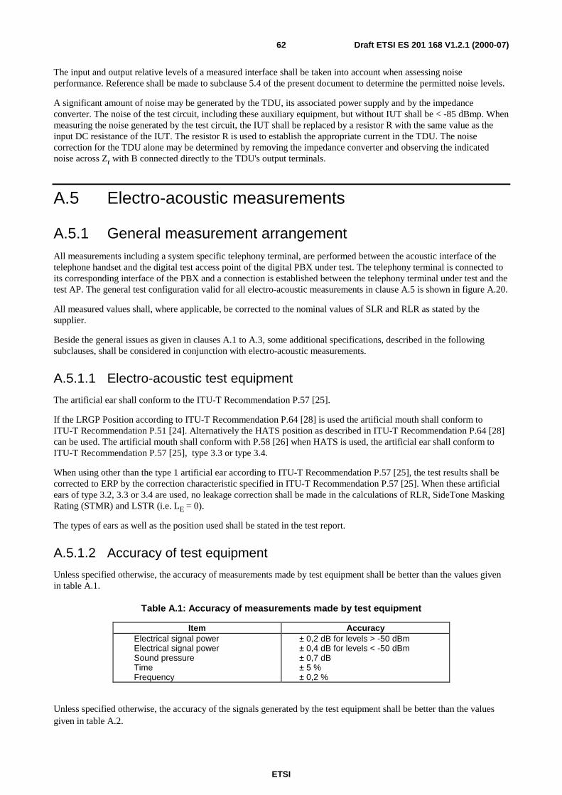
ETSI
Draft ETSI ES 201 168 V1.2.1 (2000-07)62
The input and output relative levels of a measured interface shall be taken into account when assessing noiseperformance. Reference shall be made to subclause 5.4 of the present document to determine the permitted noise levels.
A significant amount of noise may be generated by the TDU, its associated power supply and by the impedanceconverter. The noise of the test circuit, including these auxiliary equipment, but without IUT shall be < -85 dBmp. Whenmeasuring the noise generated by the test circuit, the IUT shall be replaced by a resistor R with the same value as theinput DC resistance of the IUT. The resistor R is used to establish the appropriate current in the TDU. The noisecorrection for the TDU alone may be determined by removing the impedance converter and observing the indicatednoise across Zr with B connected directly to the TDU's output terminals.
A.5 Electro-acoustic measurements
A.5.1 General measurement arrangementAll measurements including a system specific telephony terminal, are performed between the acoustic interface of thetelephone handset and the digital test access point of the digital PBX under test. The telephony terminal is connected toits corresponding interface of the PBX and a connection is established between the telephony terminal under test and thetest AP. The general test configuration valid for all electro-acoustic measurements in clause A.5 is shown in figure A.20.
All measured values shall, where applicable, be corrected to the nominal values of SLR and RLR as stated by thesupplier.
Beside the general issues as given in clauses A.1 to A.3, some additional specifications, described in the followingsubclauses, shall be considered in conjunction with electro-acoustic measurements.
A.5.1.1 Electro-acoustic test equipment
The artificial ear shall conform to the ITU-T Recommendation P.57 [25].
If the LRGP Position according to ITU-T Recommendation P.64 [28] is used the artificial mouth shall conform toITU-T Recommendation P.51 [24]. Alternatively the HATS position as described in ITU-T Recommendation P.64 [28]can be used. The artificial mouth shall conform with P.58 [26] when HATS is used, the artificial ear shall conform toITU-T Recommendation P.57 [25], type 3.3 or type 3.4.
When using other than the type 1 artificial ear according to ITU-T Recommendation P.57 [25], the test results shall becorrected to ERP by the correction characteristic specified in ITU-T Recommendation P.57 [25]. When these artificialears of type 3.2, 3.3 or 3.4 are used, no leakage correction shall be made in the calculations of RLR, SideTone MaskingRating (STMR) and LSTR (i.e. LE = 0).
The types of ears as well as the position used shall be stated in the test report.
A.5.1.2 Accuracy of test equipment
Unless specified otherwise, the accuracy of measurements made by test equipment shall be better than the values givenin table A.1.
Table A.1: Accuracy of measurements made by test equipment
Item AccuracyElectrical signal powerElectrical signal powerSound pressureTimeFrequency
± 0,2 dB for levels > -50 dBm± 0,4 dB for levels < -50 dBm± 0,7 dB± 5 %± 0,2 %
Unless specified otherwise, the accuracy of the signals generated by the test equipment shall be better than the valuesgiven in table A.2.
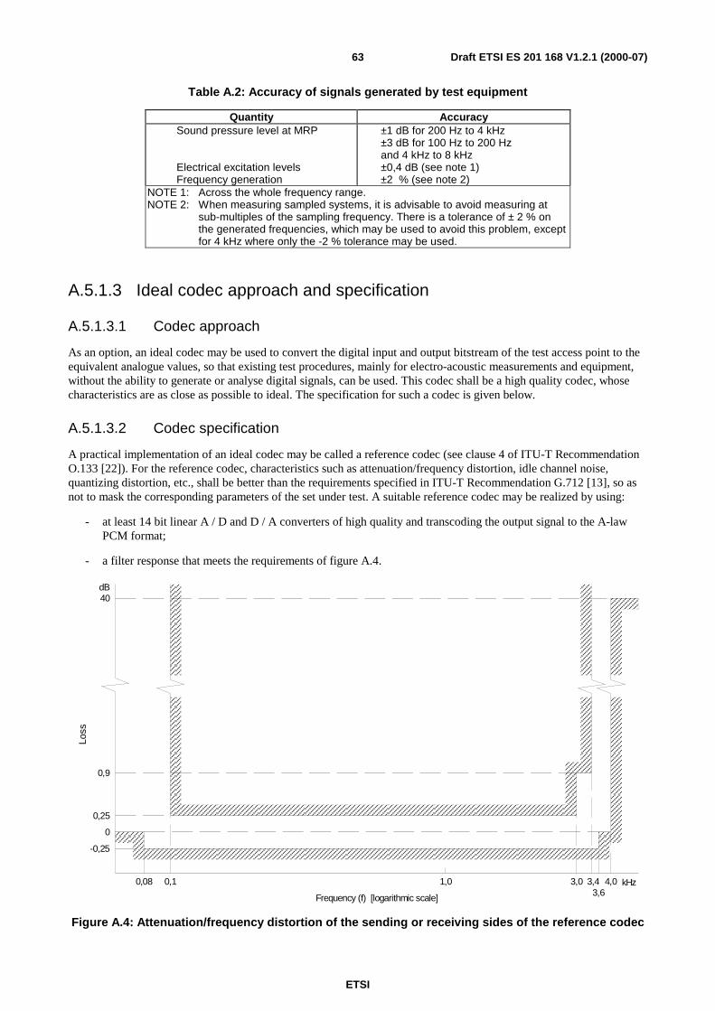
ETSI
Draft ETSI ES 201 168 V1.2.1 (2000-07)63
Table A.2: Accuracy of signals generated by test equipment
Quantity AccuracySound pressure level at MRP
Electrical excitation levelsFrequency generation
±1 dB for 200 Hz to 4 kHz±3 dB for 100 Hz to 200 Hzand 4 kHz to 8 kHz±0,4 dB (see note 1)±2 % (see note 2)
NOTE 1: Across the whole frequency range.NOTE 2: When measuring sampled systems, it is advisable to avoid measuring at
sub-multiples of the sampling frequency. There is a tolerance of ± 2 % onthe generated frequencies, which may be used to avoid this problem, exceptfor 4 kHz where only the -2 % tolerance may be used.
A.5.1.3 Ideal codec approach and specification
A.5.1.3.1 Codec approach
As an option, an ideal codec may be used to convert the digital input and output bitstream of the test access point to theequivalent analogue values, so that existing test procedures, mainly for electro-acoustic measurements and equipment,without the ability to generate or analyse digital signals, can be used. This codec shall be a high quality codec, whosecharacteristics are as close as possible to ideal. The specification for such a codec is given below.
A.5.1.3.2 Codec specification
A practical implementation of an ideal codec may be called a reference codec (see clause 4 of ITU-T RecommendationO.133 [22]). For the reference codec, characteristics such as attenuation/frequency distortion, idle channel noise,quantizing distortion, etc., shall be better than the requirements specified in ITU-T Recommendation G.712 [13], so asnot to mask the corresponding parameters of the set under test. A suitable reference codec may be realized by using:
- at least 14 bit linear A / D and D / A converters of high quality and transcoding the output signal to the A-lawPCM format;
- a filter response that meets the requirements of figure A.4.
3,03,6
3,4 4,0 kHz1,00,10,08
Frequency (f) [logarithmic scale]
-0,25
0
0,25
0,9
40dB
Loss
Figure A.4: Attenuation/frequency distortion of the sending or receiving sides of the reference codec
ETSI
Draft ETSI ES 201 168 V1.2.1 (2000-07)64
Definition of the analogue 0 dBr point:
D / A converter: a Digital Test Sequence (DTS) representing the PCM equivalent of an analogue sinewave signalwhose root mean square (rms) value is 3,14 dB (A-law) below the maximum full-load capacity ofthe codec, shall generate 0 dBm across a 600 Ω load;
A / D converter: a 0 dBm signal generated from a 600 Ω source, shall give the DTS representing the PCMequivalent of an analogue sinewave signal, whose rms value is 3,14 dB (A-law) below themaximum full-load capacity of the codec.
DTS is defined as a periodic sequence of character signals as defined in table 5 of ITU-T Recommendation G.711 [12].
NOTE: For further information, see figure 6 of ITU-T Recommendation G.101 [4].
Analogue interface: The output and input impedances, return loss and longitudinal conversion losses of the analogueinterface of the reference codec shall be in accordance with subclause 3.1.1 of ITU-T Recommendation O.133 [22].
Digital interface: The fundamental requirements for the reference codec digital interface are given in the appropriateITU-T Recommendations (e.g., ITU-T Recommendation G.703 [11]).
A.5.1.4 Selective measurements
It shall be the responsibility of the test house to select an appropriate bandwidth for selective measurements.
For single frequency noise measurements the procedures of subclauses A.4.5.1.1 and A.4.5.1.2 are followed with thedigital and analogue signal analysers in the frequency selective mode. Both in-band and out-of-band single frequencynoise components may then be measured.
A.5.1.5 Use of digital loss or gain pads
According to the rules given in clause 4, the use of digital loss or gain pads in the speech path shall be stated by thesupplier. If the pads are included in the path between test point of the PBX and system specific telephony terminal, thesepads shall be switched inoperative during all transmission measurement, with the exception of:
- SLR (see subclause A.5.2.2.1);
- RLR (see subclause A.5.2.2.2);
- Echo Loss (see subclause A.5.2.4);
- TELR (see subclause A.5.2.5);
- Stability loss (see subclause A.5.2.6).
Basically all transmission measurements in conjunction with a system specific telephony terminal, are performed only upto the test point of the PBX. If digital pads are included in the path between test point and the interface KD of the PBX(to be stated by the supplier), test results of SLR, RLR, EL and stability loss shall be corrected with the nominal valuesof the digital loss or gain pads in both transmission directions.
A.5.1.6 Use of echo control devices
If the supplier declares that an echo control device is needed in order to meet the requirements of the present documentit shall be switched operative in all cases if not stated otherwise.
A.5.1.7 Use of a Reference Portable Part (RPP)
In cases where the PBX supplier does not provide the PP of a cordless system but - solely - a standardized air interfacethe transmission characteristics can be verified using a RPP.
The RPP shall provide the equivalent of true air interface measurements and therefore shall not contain circuitry whichwill modify the true air interface speech frequency performance. For measurement purposes, the RPP shall have a testaccess point as specified in relevant standards.
ETSI
Draft ETSI ES 201 168 V1.2.1 (2000-07)65
A.5.2 Specific electro-acoustic measurements
A.5.2.1 Sensitivity - frequency response
A.5.2.1.1 Sending Sensitivity
a) The handset is mounted in the Loudness Rating Guard ring Position (LRGP) (see ITU-T RecommendationP.64 [28]). The earpiece is sealed to the knife-edge of an artificial ear. Alternatively the HATS position (seeITU-T Recommendation P.64 [28]) can be used. The pressure force used for handset application shall beindicated in the test report.
b) A sinewave signal with a sound pressure level of -4,7 dBPa shall be applied at the MRP as described inITU-T Recommendation P.64 [28].
c) Measurements shall be made at one-twelfth octave intervals as given by the R.40 series of preferred numbers inISO 3 [36] for frequencies from 100 Hz to 4 kHz inclusive.
d) At each frequency, the output level for a sound pressure level of -4,7 dBPa shall be measured and the sendingsensitivity shall be expressed in dBV/Pa.
A.5.2.1.2 Receiving Sensitivity
a) The handset is mounted in the Loudness Rating Guard ring Position (LRGP) (see ITU-T RecommendationP.64 [28]). The earpiece is sealed to the knife-edge of an artificial ear. Alternatively the HATS position (seeITU-T Recommendation P.64 [28]) can be used. The pressure force used for handset application shall beindicated in the test report.
b) A digital signal generator shall be connected at the digital test access point of the PBX, delivering a signalequivalent to a sinewave level of -16 dBm0 (can be derived from clause 11 of ITU-T RecommendationP.64 [28]).
c) Measurements shall be made at one twelfth-octave intervals as given by the R.40 series of preferred numbers inISO 3 [36] for frequencies from 100 Hz to 4 kHz inclusive.
d) At each frequency, the sound pressure in the artificial ear shall be measured by connecting a suitable measuringset to the artificial ear and the receiving sensitivity shall be expressed in dBPa/V.
A.5.2.2 Loudness Ratings (LR)
A.5.2.2.1 Send Loudness Rating (SLR)
a) The connection is established and the handset is mounted as described in subclause A.5.2.1.1. The sendingsensitivity shall be measured as described in A.5.2.1.1 but at each of the 14 frequencies (bands 4 to 17) given intable 1 of ITU-T Recommendation P.79 [29].
b) The SLR shall be calculated according ITU-T Recommendation P.79 [29].
NOTE: ITU-T Recommendation P.64 [28] allows the use of alternative signal sources for measurement of LRs. Ifsuch a signal source is used, it is the responsibility of the test house to ensure that the method used isequivalent to that described above.
A.5.2.2.2 Receive Loudness Rating (RLR)
a) A connection is established and the handset is mounted as described in subclause A.5.2.1.2. The receivingsensitivity shall be measured as described in A.5.2.1.2 at each of the 14 frequencies (bands 4 to 17) given intable 1 of ITU-T Recommendation P.79 [29].
b) The RLR shall be calculated according to ITU-T Recommendation P.79 [29].
ETSI
Draft ETSI ES 201 168 V1.2.1 (2000-07)66
c) The artificial ear sensitivity shall be corrected using the leakage correction of table 2 of ITU-T RecommendationP.79 [29] if artificial ear type 1 is used.
NOTE: ITU-T Recommendation P.64 [28] allows the use of alternative signal sources for measurement of LRs. Ifsuch a signal source is used, it is the responsibility of the test house to ensure that the method used isequivalent to that described above.
A.5.2.3 Sidetone
For the tests described in subclauses A.5.2.3.1 and A.5.2.3.2, the digital input of the test access point shall be driven bya PCM signal corresponding to decoder value number 1.
A.5.2.3.1 Talker sidetone
a) A connection is established and the handset is mounted as described in subclause A.5.2.1.1. A sinewave signalwith a sound pressure level of -4,7 dBPa shall be applied at the MRP. For each frequency (bands 1 to 20) givenin table 3 of ITU-T Recommendation P.79 [29], the sound pressure in the artificial ear shall be measured. Thesensitivity of the sidetone path i.e. the sidetone path loss, expressed in dB, shall be calculated.
b) Where a user controlled volume control is provided, the measurements shall be carried out at a setting, which isas close as possible to the declared nominal value of the RLR.
c) The STMR, expressed in dB, shall be calculated according to ITU-T Recommendation P.79 [29].
NOTE: ITU-T Recommendation P.64 [28] allows the use of alternative signal sources for measurement of LRs. Ifsuch a signal source is used, it is the responsibility of the test house to ensure that the method used isequivalent to that described above.
A.5.2.3.2 Listener sidetone
a) The diffuse sound field is calibrated in the absence of any local obstacles. The averaged field shall be uniform towithin ± 3 dB within a radius of 0,15 m of the MRP, when measured in one-third octave bands according to IEC61260 [35] from 100 Hz to 8 kHz (bands 1 to 20).
NOTE 1: The pressure intensity index, as defined in ISO 9614-1 [37], may prove to be a suitable method forassessing the diffuse field.
NOTE 2: Where more than one loudspeaker is used to produce the desired sound field, the loudspeakers mayrequire to be fed with non coherent electrical signals to eliminate standing waves and other interferenceeffects.
b) For measurement of LSTR a connection is established and the handset is mounted as described insubclause A.5.2.1.1.
c) Where a user controlled volume control is provided, the measurements shall be carried out at a setting which is asclose as possible to the declared nominal value of the RLR.
d) Where adaptive techniques or voice switching circuits are not used (need to be declared by the supplier), thespectrum of the diffuse sound field shall be a band limited "pink noise" (50 Hz to 10 kHz) according to annex Bof ITU-T Recommendation P.64 [28], to within ±3 dB and the level shall be adjusted to 70 dB(A)(-24 dBPa(A)). The tolerance for this level adjustment is ±1 dB. In other cases the level shall be adjusted to50 dB(A) (-44 dBPa(A)), with a tolerance of ±1 dB.
e) Measurements shall be made on one-third octave bands according to IEC 61260 [35] for the 20 bands centred at100 Hz to 8 kHz (bands 1 to 20). For each band the sound pressure in the artificial ear shall be measured byconnecting a suitable measuring set to the artificial ear.
NOTE 3: There may be problems with the signal to noise ratio. If it is less than 10 dB in any band, the microphonenoise level and the noise level of any out-of-band signals need to be subtracted from the measuredsidetone level (power subtraction).
ETSI
Draft ETSI ES 201 168 V1.2.1 (2000-07)67
f) The listener sidetone path loss is expressed in dB and the LSTR shall be calculated according toITU-T Recommendation P.79 [29].
A.5.2.3.3 D factor
The sending sensitivity, Ssi(direct) (from MRP to the electrical interface) in free field is measured according toA.5.2.1.1 but with the pink noise signal as specified above. The sensitivity is measured for the 14 1/3-octave bandscentred at 200 to 4 000 Hz. The sensitivity is expressed in dBV/Pa.
The diffuse sound field is adjusted according to a) and d). The sending sensitivity, Ssi(diff) (from MRP to the electricalinterface) in diffuse field is measured for the 14 1/3-octave bands centred at 200 to 4 000 Hz. The sensitivity isexpressed in dBV/Pa.
The value of the D-factor shall be calculated according to ITU-T Recommendation P.79 [29], annex E, formulas E.2and E.3, over the bands from 4 to 17, using the coefficients Ki from the table E.1.
A.5.2.4 Echo Loss at the interface KD
The test configuration is shown in figure A.20.
a) A connection is established between the system specific telephony terminal and the interface KD.
b) The handset is suspended in free air in such a way, that the inherent mechanical coupling of the handset is noteffected. The testing shall be made under free field condition (the deviation from ideal free field conditions shallbe less than 1 dB). The ambient noise level shall be less than 30 dBSPL (A).
c) The attenuation from digital input to digital output of the interface KD shall be measured separately for eachecho path declared by the supplier, using a suitable of band limited (300 Hz to 3 400 Hz) test signal with a levelof -10 dBm0. Suitable test signals can be found in ITU-T Recommendation P.501 [30]. Suitable test signals maybe pulsed pink noise or a Composite Source Signal.
d) A training sequence consisting of 10 s artificial voice male and female each is applied before the actualmeasurement. The EL at the interface KD is calculated by means of Fast Fourier Transformation (FFT) for eachecho path separately. The averaged output power density spectrum is referred to averaged power densityspectrum of the test signal using the identical parts of the test signal.
e) In general the echo path may consist of various echo paths resulting from echoes at different points of theconnection. These typically result in different echo impulse responses which are separate in time. If the declaredecho paths cannot be separated, a separation method as described in annex B shall be used in order to separatethe individual echoes. Care should be taken to use an appropriate test signal with a repetition period > theexpected maximum echo delay and to use the correct window settings in order to extract the individual echoimpulses from the impulse response derived from the inverse Fourier transformation as described in annex B.
f) Finally the EL is calculated according to ITU-T Recommendation G.122 [9].
If no interface KD is available for testing, the tests should be made between the system specific terminal and the testaccess point. In this case the sum of the losses in both directions of the path „test point to interface KD" shall be addedto the measured value.
A.5.2.5 Talker Echo Loudness Rating
For the TELR tests a reference telephone e.g. a reference portable part according to TBR 10 [3] is required whichallows the defined electrical access to the terminal. The test configurations for cases 1 and 2 are shown in figures A.21and A.22, respectively.
In cases where only the acoustical access to the terminal is available the test shall be conducted as described in annex Bof TBR 10 [3]. If different delays than those described in TBR 10 [3] are expected, the method needs to be adaptedaccordingly.
Case 1: Connection to an interface KD:
ETSI
Draft ETSI ES 201 168 V1.2.1 (2000-07)68
a) A connection is established between the system specific telephony terminal and the interface KD leaving thetransmit and receive direction of the KD interface completely separated.
b) The attenuation from the electrical input of the reference terminal to the electrical output of the system specificreference telephone shall be measured separately for each echo path inside the PBX declared by the supplier,using a band limited (300 Hz to 3 400 Hz) test signal with an appropriate level (e.g. –10 dBm0). Suitable testsignals can be found in ITU-T Recommendation P.501 [30]. Suitable test signals may be pulsed pink noise or aComposite Source Signal.
c) A training sequence consisting of 10 s artificial voice male and female each is applied before the actualmeasurement. The TELR at the acoustical interface is calculated by means of Fast Fourier Transformation (FFT)for each echo path separately. The averaged output power density spectrum is referred to averaged power densityspectrum of the test signal using the identical parts of the test signal.
d) In general the echo path may consist of various echo paths resulting from echoes at different points of theconnection. These typically result in different echo impulse responses which are separate in time. If the declaredecho paths cannot be separated, a separation method as described in annex B shall be used in order to separatethe individual echoes. Care should be taken to use an appropriate test signal with a repetition period the expectedmaximum echo delay and to use the correct window settings in order to extract the individual echo impulses fromthe impulse response derived from the inverse Fourier transformation as described in annex B.
e) Finally the TELR is calculated according to ITU-T Recommendation G.122 [9].
Case 2: Connection to an interface K2:
a) A connection is established between the system specific telephony terminal and the interface K2, which shall beterminated with its nominal impedance.
b) The attenuation from the electrical input of the (system specific) reference terminal to electrical output of thereference telephone shall be measured separately for each echo path inside the PBX declared by the supplier,using a band limited (300 Hz to 3 400 Hz) test signal with an appropriate level (e.g. –10 dBm0). Suitable testsignals can be found in ITU-T Recommendation P.501 [30]. Suitable test signals may be pulsed pink noise or aComposite Source Signal.
c) A training sequence consisting of 10 s artificial voice male and female each is applied before the actualmeasurement. The TELR at the acoustical interface is calculated by means of Fast Fourier Transformation (FFT)for each echo path separately. The averaged output power density spectrum is referred to averaged power densityspectrum of the test signal using the identical parts of the test signal.
d) In general the echo path may consist of various echo paths resulting from echoes at different points of theconnection. These typically result in different echo impulse responses which are separate in time. If the declaredecho paths cannot be separated, a separation method as described in annex B shall be used in order to separatethe individual echoes. Care should be taken to use an appropriate test signal with a repetition period > theexpected maximum echo delay and to use the correct window settings in order to extract the individual echoimpulses from the impulse response derived from the inverse Fourier transformation as described in annex B.
e) Finally the TELR is calculated according to ITU-T Recommendation G.122 [9].
Case 3: Network echo control:
a) A connection is established
aa) between the system specific telephony reference terminal and the interface KD,
bb) between the system specific telephony reference terminal and the interface K2,
which shall be terminated with the test network echo path according to figures A.23 and A.24, respectively.
b) The attenuation from the electrical input of the (system specific) reference terminal to electrical output of thereference telephone shall be measured separately for each echo path inside the PBX declared by the supplier,using a band limited (300 Hz to 3 400 Hz) test signal with an appropriate level (e.g. –10 dBm0). Suitable testsignals can be found in ITU-T Recommendation P.501 [30]. Suitable test signals may be pulsed pink noise or aComposite Source Signal.
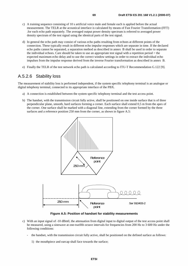
ETSI
Draft ETSI ES 201 168 V1.2.1 (2000-07)69
c) A training sequence consisting of 10 s artificial voice male and female each is applied before the actualmeasurement. The TELR at the acoustical interface is calculated by means of Fast Fourier Transformation (FFT).for each echo path separately. The averaged output power density spectrum is referred to averaged powerdensity spectrum of the test signal using the identical parts of the test signal.
d) In general the echo path may consist of various echo paths resulting from echoes at different points of theconnection. These typically result in different echo impulse responses which are separate in time. If the declaredecho paths cannot be separated, a separation method as described in annex B shall be used in order to separatethe individual echoes. Care should be taken to use an appropriate test signal with a repetition period > theexpected maximum echo delay and to use the correct window settings in order to extract the individual echoimpulses from the impulse response derived from the inverse Fourier transformation as described in annex B.
e) Finally the TELR of the test network echo path is calculated according to ITU-T Recommendation G.122 [9].
A.5.2.6 Stability loss
The measurement of stability loss is performed independent, if the system specific telephony terminal is an analogue ordigital telephony terminal, connected to its appropriate interface of the PBX.
a) A connection is established between the system specific telephony terminal and the test access point.
b) The handset, with the transmission circuit fully active, shall be positioned on one inside surface that is of threeperpendicular plane, smooth, hard surfaces forming a corner. Each surface shall extend 0,5 m from the apex ofthe corner. One surface shall be marked with a diagonal line, extending from the corner formed by the threesurfaces and a reference position 250 mm from the corner, as shown in figure A.5:
Referencepoint
250mm
250mm Referencepoint
Ser 910403-2
Figure A.5: Position of handset for stability measurements
c) With an input signal of -10 dBm0, the attenuation from digital input to digital output of the test access point shallbe measured, using a sinewave at one-twelfth octave intervals for frequencies from 200 Hz to 3 600 Hz under thefollowing conditions:
- the handset, with the transmission circuit fully active, shall be positioned on the defined surface as follows:
1) the mouthpiece and earcap shall face towards the surface;
ETSI
Draft ETSI ES 201 168 V1.2.1 (2000-07)70
2) the handset shall be placed centrally, the diagonal line with the earcap nearer to the apex of the corner;
3) the extremity of the handset shall coincide with the normal to the reference point, as shown in figure A.5.
A.5.2.7 Distortion
A.5.2.7.1 Sending
A.5.2.7.1.1 Method 1
a) A connection is established between the system specific telephony terminal and the test access point of the PBX.The handset is mounted at the LRGP and the earpiece is sealed to the knife-edge of the artificial ear.Alternatively the HATS position (see ITU-T Recommendation P.64 [28]) can be used. The pressure force usedfor handset application shall be indicated in the test report.
b) A band-limited noise signal corresponding to ITU-T Recommendation O.131 [20], shall be applied at the MRP.The level of this signal is adjusted until the output at the test access point is -10 dBm0. The level of the signal atthe MRP in dBPa is then the ARL.
c) The test signal shall be applied at the following levels relative to ARL:
-45 dB, -40 dB, -35 dB, -30 dB, -24 dB, -20 dB, -17 dB, -10 dB, -5 dB, 0 dB, 4 dB, 7 dB.
d) The ratio of signal to total distortion power of the digital signal output shall be measured (see annex A of ITU-TRecommendations Q.551 [31] and O.131 [20]).
A.5.2.7.1.2 Method 2
a) A connection is established and the handset is mounted as described in subclause A.5.2.7.1.1.
b) A sine-wave signal with a frequency in the range 1 004 Hz to 1 025 Hz shall be applied at the MRP. The level ofthis signal is adjusted until the output of the test access point is -10 dBm0. The level of the signal at the MRPin dBPa is then the ARL.
c) The test signal shall be applied at the following levels relative to ARL:
-35 dB, -30 dB, -25 dB, -20 dB, -15 dB, -10 dB, -5 dB, 0 dB, 7 dB, 10 dB.
d) The ratio of the signal to total distortion power of the digital signal output shall be measured with thepsophometric noise weighting (see ITU-T Recommendations Q.551 [31] and O.132 [21]).
A.5.2.7.2 Receiving
A.5.2.7.2.1 Method 1
a) A connection is established and the handset is mounted as described in subclause A.5.2.7.1.1.
b) A digitally simulated band-limited noise signal corresponding to ITU-T Recommendation O.131 [20] shall beapplied at the input of the test access point at the following levels:
-55 dBm0, -50 dBm0, -45 dBm0, -40 dBm0, -34 dBm0, -30 dBm0, -27 dBm0, -20 dBm0, -15 dBm0, -10 dBm0,-6 dBm0, -3 dBm0.
c) The ratio of signal to total distortion power shall be measured in the artificial ear (see annex A of ITU-TRecommendations Q.551 [31] and O.131 [20]).
A.5.2.7.2.2 Method 2
a) A connection is established and the handset is mounted as described in subclause A.5.2.7.1.1.
ETSI
Draft ETSI ES 201 168 V1.2.1 (2000-07)71
b) A digitally simulated sine-wave signal with a frequency in the range 1 004 Hz to 1 025 Hz shall be applied at theinput of the test access point at the following levels:
-45 dBm0, -40 dBm0, -35 dBm0, -30 dBm0, -25 dBm0, -20 dBm0, -15 dBm0, -10 dBm0, -3 dBm0, 0 dBm0.
c) The ratio of the signal-to-total distortion power shall be measured with the psophometric noise weighting in theartificial ear (see ITU-T Recommendations Q.551 [31] and O.132 [21]).
A.5.2.7.3 Sidetone
a) A connection is established and the handset is mounted as described in subclause A.5.2.7.1.1.
b) An instrument capable of measuring the third harmonic distortion of signals with fundamental frequencies in therange of 315 Hz to 1 kHz shall be connected to the artificial ear.
c) The digital input of the test access point shall be driven by a PCM signal, corresponding to decoder valuenumber 1.
d) A pure-tone signal of -4,7 dBPa shall be applied at the MRP at frequencies of 315 Hz, 500 Hz and 1 kHz. Foreach frequency, the third harmonic distortion shall be measured in the artificial ear.
A.5.2.8 Variation of gain with input level
A.5.2.8.1 Sending
a) A connection is established and the handset is mounted as described in subclause A.5.2.7.1.1.
b) A sine-wave signal with a frequency in the range 1 004 Hz to 1 025 Hz shall be applied at the MRP. The level ofthis signal is adjusted, until the output at the test access point is -10 dBm0. The level of the signal at the MRPin dBPa is then the ARL.
c) The test signal shall be applied at the following levels relative to ARL:
-45 dB, -40 dB, -35 dB, -30 dB, -25 dB, -20 dB, -15 dB, -10 dB, -5 dB, 0 dB, 4 dB, 10 dB, 13 dB.
d) The variation of gain relative to the gain for the ARL shall be measured.
NOTE: Selective measurement may be used to avoid the effects of ambient noise.
A.5.2.8.2 Receiving
a) A connection is established and the handset is mounted as described in subclause A.5.2.7.1.1.
b) A digitally simulated sine-wave signal with a frequency in the range 1 004 Hz to 1 025 Hz shall be applied at thedigital interface at the following levels:
-50 dBm0, -45 dBm0, -40 dBm0, -35 dBm0, -30 dBm0, -25 dBm0, -20 dBm0, -15 dBm0, -10 dBm0, -6 dBm0,0 dBm0, 3 dBm0.
c) The variation of gain relative to the gain at an input level of -10 dBm0 shall be measured in the artificial ear.
NOTE: Selective measurement may be used to avoid the effects of ambient noise.
A.5.2.9 Out-of-band signals
A.5.2.9.1 Discrimination against out-of-band input signal
a) A connection is established and the handset is mounted as described in subclause A.5.2.7.1.1.
b) Input signals at frequencies of 4,65 kHz, 5 kHz, 6 kHz, 6,5 kHz, 7 kHz and 7,5 kHz are applied at the MRP witha level of -4,7 dBPa.
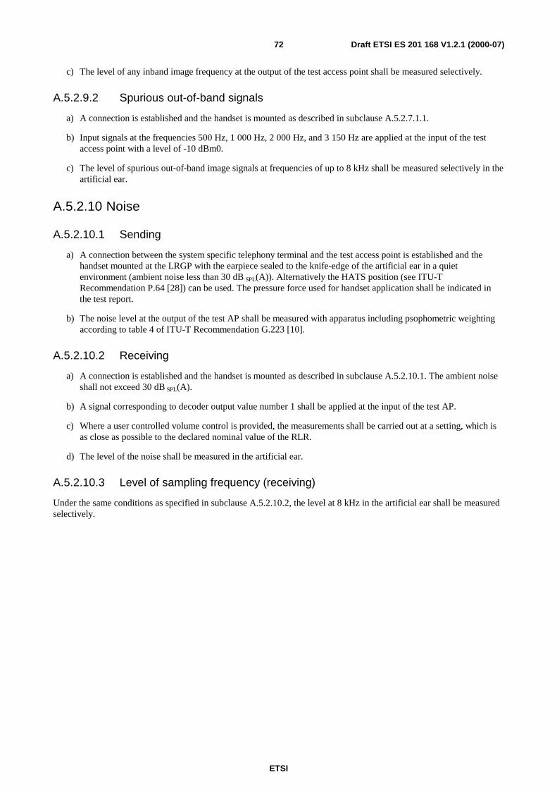
ETSI
Draft ETSI ES 201 168 V1.2.1 (2000-07)72
c) The level of any inband image frequency at the output of the test access point shall be measured selectively.
A.5.2.9.2 Spurious out-of-band signals
a) A connection is established and the handset is mounted as described in subclause A.5.2.7.1.1.
b) Input signals at the frequencies 500 Hz, 1 000 Hz, 2 000 Hz, and 3 150 Hz are applied at the input of the testaccess point with a level of -10 dBm0.
c) The level of spurious out-of-band image signals at frequencies of up to 8 kHz shall be measured selectively in theartificial ear.
A.5.2.10 Noise
A.5.2.10.1 Sending
a) A connection between the system specific telephony terminal and the test access point is established and thehandset mounted at the LRGP with the earpiece sealed to the knife-edge of the artificial ear in a quietenvironment (ambient noise less than 30 dB SPL(A)). Alternatively the HATS position (see ITU-TRecommendation P.64 [28]) can be used. The pressure force used for handset application shall be indicated inthe test report.
b) The noise level at the output of the test AP shall be measured with apparatus including psophometric weightingaccording to table 4 of ITU-T Recommendation G.223 [10].
A.5.2.10.2 Receiving
a) A connection is established and the handset is mounted as described in subclause A.5.2.10.1. The ambient noiseshall not exceed 30 dB SPL(A).
b) A signal corresponding to decoder output value number 1 shall be applied at the input of the test AP.
c) Where a user controlled volume control is provided, the measurements shall be carried out at a setting, which isas close as possible to the declared nominal value of the RLR.
d) The level of the noise shall be measured in the artificial ear.
A.5.2.10.3 Level of sampling frequency (receiving)
Under the same conditions as specified in subclause A.5.2.10.2, the level at 8 kHz in the artificial ear shall be measuredselectively.
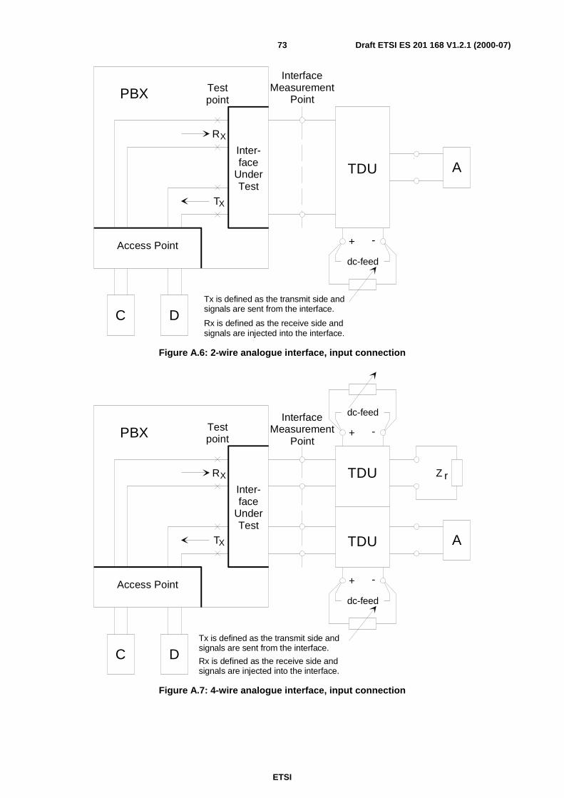
ETSI
Draft ETSI ES 201 168 V1.2.1 (2000-07)73
T
RX
X
TestpointPBX
Inter-face
UnderTest
Access Point
dc-feed
+ -
TDU A
InterfaceMeasurement
Point
C DTx is defined as the transmit side andsignals are sent from the interface.
Rx is defined as the receive side andsignals are injected into the interface.
Figure A.6: 2-wire analogue interface, input connection
T
RX
X
TestpointPBX
Inter-face
UnderTest
Access Point
A
InterfaceMeasurement
Point
C DTx is defined as the transmit side andsignals are sent from the interface.
Rx is defined as the receive side andsignals are injected into the interface.
dc-feed
dc-feed
+ -
+ -
Z rTDU
TDU
Figure A.7: 4-wire analogue interface, input connection
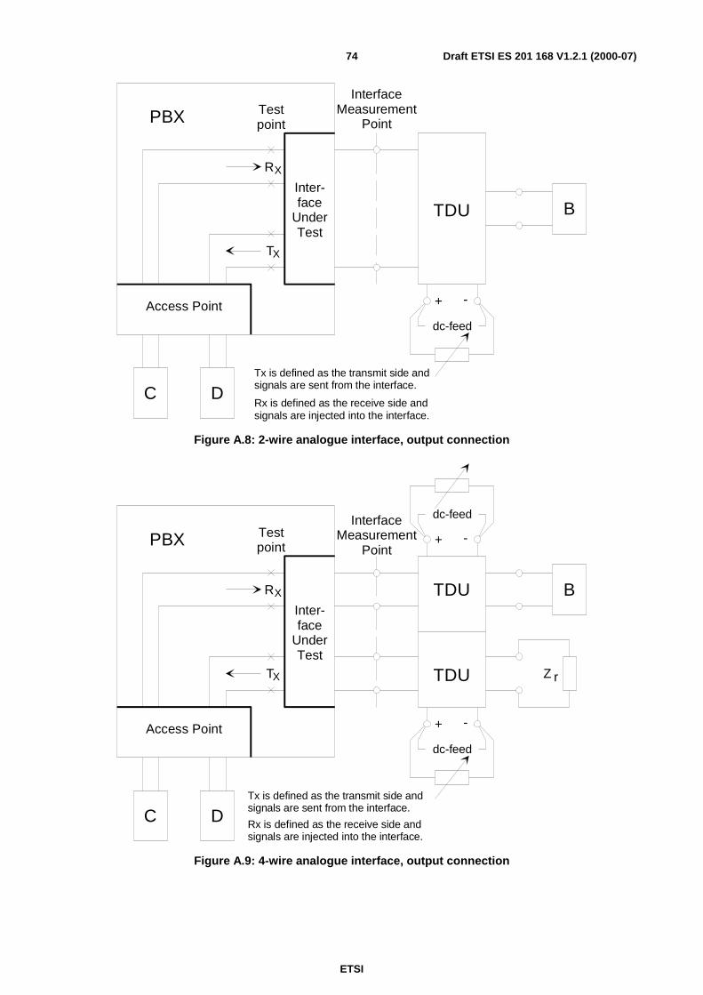
ETSI
Draft ETSI ES 201 168 V1.2.1 (2000-07)74
T
RX
X
TestpointPBX
Inter-face
UnderTest
Access Point
dc-feed
+ -
TDU
InterfaceMeasurement
Point
C DTx is defined as the transmit side andsignals are sent from the interface.
Rx is defined as the receive side andsignals are injected into the interface.
B
Figure A.8: 2-wire analogue interface, output connection
T
RX
X
TestpointPBX
Inter-face
UnderTest
Access Point
InterfaceMeasurement
Point
C DTx is defined as the transmit side andsignals are sent from the interface.
Rx is defined as the receive side andsignals are injected into the interface.
dc-feed
dc-feed
+ -
+ -
Z r
TDU
TDU
B
Figure A.9: 4-wire analogue interface, output connection
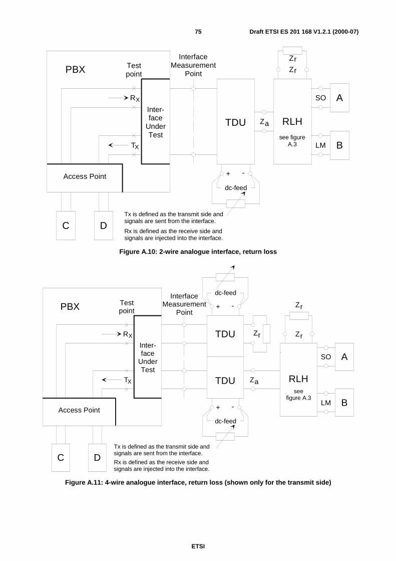
ETSI
Draft ETSI ES 201 168 V1.2.1 (2000-07)75
T
RX
X
TestpointPBX
Inter-face
UnderTest
Access Point
dc-feed
+ -
TDU
A
InterfaceMeasurement
Point
C DTx is defined as the transmit side andsignals are sent from the interface.
Rx is defined as the receive side andsignals are injected into the interface.
B
Z
Zr
r
SO
LM
Za RLH
see figureA.3
Figure A.10: 2-wire analogue interface, return loss
T
RX
X
TestpointPBX
Inter-face
UnderTest
Access Point
InterfaceMeasurement
Point
C DTx is defined as the transmit side andsignals are sent from the interface.
Rx is defined as the receive side andsignals are injected into the interface.
dc-feed
dc-feed
+ -
+ -
ZrTDU
TDU
A
LM
SO
Z
Zr
r
Za RLHsee
figure A.3B
Figure A.11: 4-wire analogue interface, return loss (shown only for the transmit side)
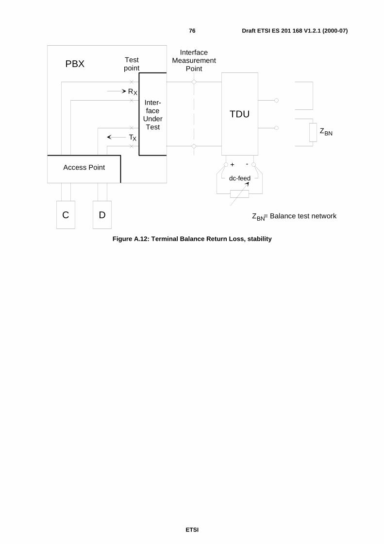
ETSI
Draft ETSI ES 201 168 V1.2.1 (2000-07)76
T
RX
X
TestpointPBX
Inter-face
UnderTest
Access Point
dc-feed
+ -
InterfaceMeasurement
Point
TDU
C D
ZBN
ZBN= Balance test network
Figure A.12: Terminal Balance Return Loss, stability
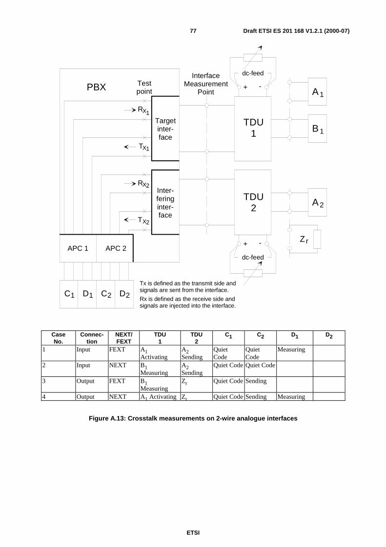
ETSI
Draft ETSI ES 201 168 V1.2.1 (2000-07)77
dc-feed
dc-feed
+ -
+ -
PBX Testpoint
RX
TX
1
1
RX2
TX2
Targetinter-face
Inter-feringinter-face
APC 1 APC 2
C1 D C D1 2 2
TDU1
TDU2
InterfaceMeasurement
Point
B 1
A 2
Tx is defined as the transmit side andsignals are sent from the interface.
Rx is defined as the receive side andsignals are injected into the interface.
A 1
Zr
CaseNo.
Connec-tion
NEXT/FEXT
TDU1
TDU2
C1 C2 D1 D2
1 Input FEXT A1Activating
A2Sending
QuietCode
QuietCode
Measuring
2 Input NEXT B1Measuring
A2Sending
Quiet Code Quiet Code
3 Output FEXT B1Measuring
Zr Quiet Code Sending
4 Output NEXT A1 Activating Zr Quiet Code Sending Measuring
Figure A.13: Crosstalk measurements on 2-wire analogue interfaces
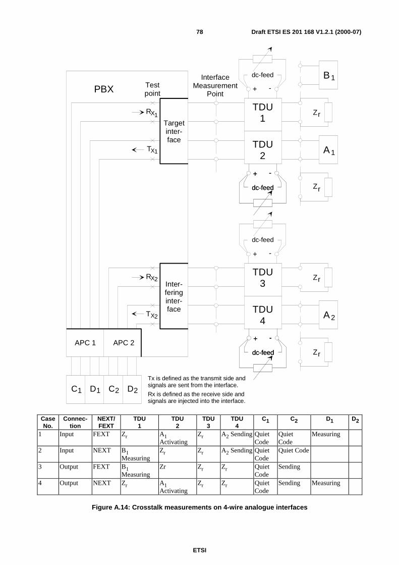
ETSI
Draft ETSI ES 201 168 V1.2.1 (2000-07)78
PBX Testpoint
RX
TX
1
1
RX2
TX2
Targetinter-face
Inter-feringinter-face
APC 1 APC 2
C1 D C D1 2 2
InterfaceMeasurement
Point
A 1
A 2
Tx is defined as the transmit side andsignals are sent from the interface.
Rx is defined as the receive side andsignals are injected into the interface.
Zr
ZrTDU
1
TDU2
TDU3
TDU4
Zr
Zr
B 1
dc-feed
+ -
dc-feed
+ -
dc-feed
+ -
dc-feed
+ -
dc-feed
+ -
dc-feed
+ -
CaseNo.
Connec-tion
NEXT/FEXT
TDU1
TDU2
TDU3
TDU4
C1 C2 D1 D2
1 Input FEXT Zr A1Activating
Zr A2 Sending QuietCode
QuietCode
Measuring
2 Input NEXT B1Measuring
Zr Zr A2 Sending QuietCode
Quiet Code
3 Output FEXT B1Measuring
Zr Zr Zr QuietCode
Sending
4 Output NEXT Zr A1Activating
Zr Zr QuietCode
Sending Measuring
Figure A.14: Crosstalk measurements on 4-wire analogue interfaces
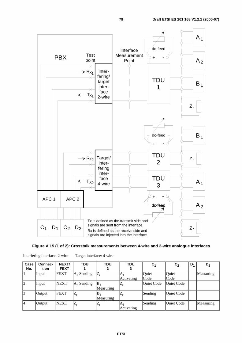
ETSI
Draft ETSI ES 201 168 V1.2.1 (2000-07)79
PBX Testpoint
RX
TX
1
1
RX2
TX2
Inter-fering/targetinter-face
2-wire
Target/inter-feringinter-face
4-wire
APC 1 APC 2
C1 D C D1 2 2
InterfaceMeasurement
Point
B 1
A 1
Tx is defined as the transmit side andsignals are sent from the interface.
Rx is defined as the receive side andsignals are injected into the interface.
Zr
TDU1
TDU2
TDU3
Zr
Zr
A 1
B 1
A 2
A 2
dc-feed
+ -
dc-feed
+ -
dc-feed
+ -
dc-feed
+ -
Figure A.15 (1 of 2): Crosstalk measurements between 4-wire and 2-wire analogue interfaces
Interfering interface: 2-wire Target interface: 4-wire
CaseNo.
Connec-tion
NEXT/FEXT
TDU1
TDU2
TDU3
C1 C2 D1 D2
1 Input FEXT A2 Sending Zr A1Activating
QuietCode
QuietCode
Measuring
2 Input NEXT A2 Sending B1Measuring
Zr Quiet Code Quiet Code
3 Output FEXT Zr B1Measuring
Zr Sending Quiet Code
4 Output NEXT Zr Zr A1Activating
Sending Quiet Code Measuring
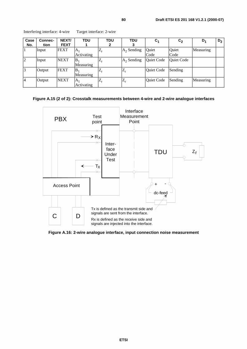
ETSI
Draft ETSI ES 201 168 V1.2.1 (2000-07)80
Interfering interface: 4-wire Target interface: 2-wire
CaseNo.
Connec-tion
NEXT/FEXT
TDU1
TDU2
TDU3
C1 C2 D1 D2
1 Input FEXT A1Activating
Zr A2 Sending QuietCode
QuietCode
Measuring
2 Input NEXT B1Measuring
Zr A2 Sending Quiet Code Quiet Code
3 Output FEXT B1Measuring
Zr Zr Quiet Code Sending
4 Output NEXT A1Activating
Zr Zr Quiet Code Sending Measuring
Figure A.15 (2 of 2): Crosstalk measurements between 4-wire and 2-wire analogue interfaces
T
RX
X
TestpointPBX
Inter-face
UnderTest
Access Point
dc-feed
+ -
TDU
InterfaceMeasurement
Point
C DTx is defined as the transmit side andsignals are sent from the interface.
Rx is defined as the receive side andsignals are injected into the interface.
Zr
Figure A.16: 2-wire analogue interface, input connection noise measurement
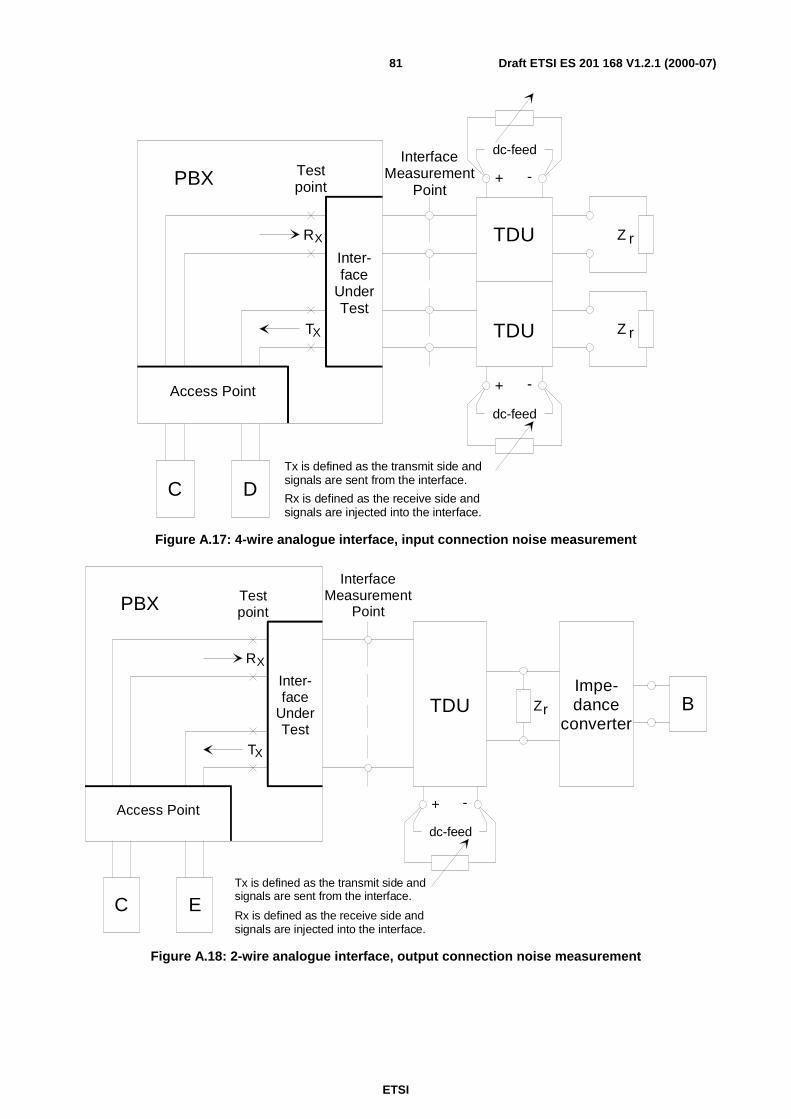
ETSI
Draft ETSI ES 201 168 V1.2.1 (2000-07)81
T
RX
X
TestpointPBX
Inter-face
UnderTest
Access Point
InterfaceMeasurement
Point
C DTx is defined as the transmit side andsignals are sent from the interface.
Rx is defined as the receive side andsignals are injected into the interface.
dc-feed
dc-feed
+ -
+ -
Z r
TDU
TDU
Z r
Figure A.17: 4-wire analogue interface, input connection noise measurement
T
RX
X
TestpointPBX
Inter-face
UnderTest
Access Point
dc-feed
+ -
TDU
InterfaceMeasurement
Point
C ETx is defined as the transmit side andsignals are sent from the interface.
Rx is defined as the receive side andsignals are injected into the interface.
BZr
Impe-dance
converter
Figure A.18: 2-wire analogue interface, output connection noise measurement
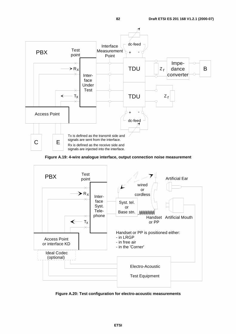
ETSI
Draft ETSI ES 201 168 V1.2.1 (2000-07)82
T
RX
X
TestpointPBX
Inter-face
UnderTest
Access Point
InterfaceMeasurement
Point
C ETx is defined as the transmit side andsignals are sent from the interface.
Rx is defined as the receive side andsignals are injected into the interface.
dc-feed
dc-feed
+ -
+ -
Z r
TDU
TDU
BImpe-dance
converterZ r
Figure A.19: 4-wire analogue interface, output connection noise measurement
T
RX
X
TestpointPBX
Inter-faceSyst.Tele-phone
Access Pointor interface KD
Syst. tel.or
Base stn.
Ideal Codec
Electro-Acoustic
Test Equipment
Artificial Ear
Artificial MouthHandsetor PP
(optional)
Handset or PP is positioned either:- in LRGP- in free air- in the 'Corner'
wiredor
cordless
Figure A.20: Test configuration for electro-acoustic measurements
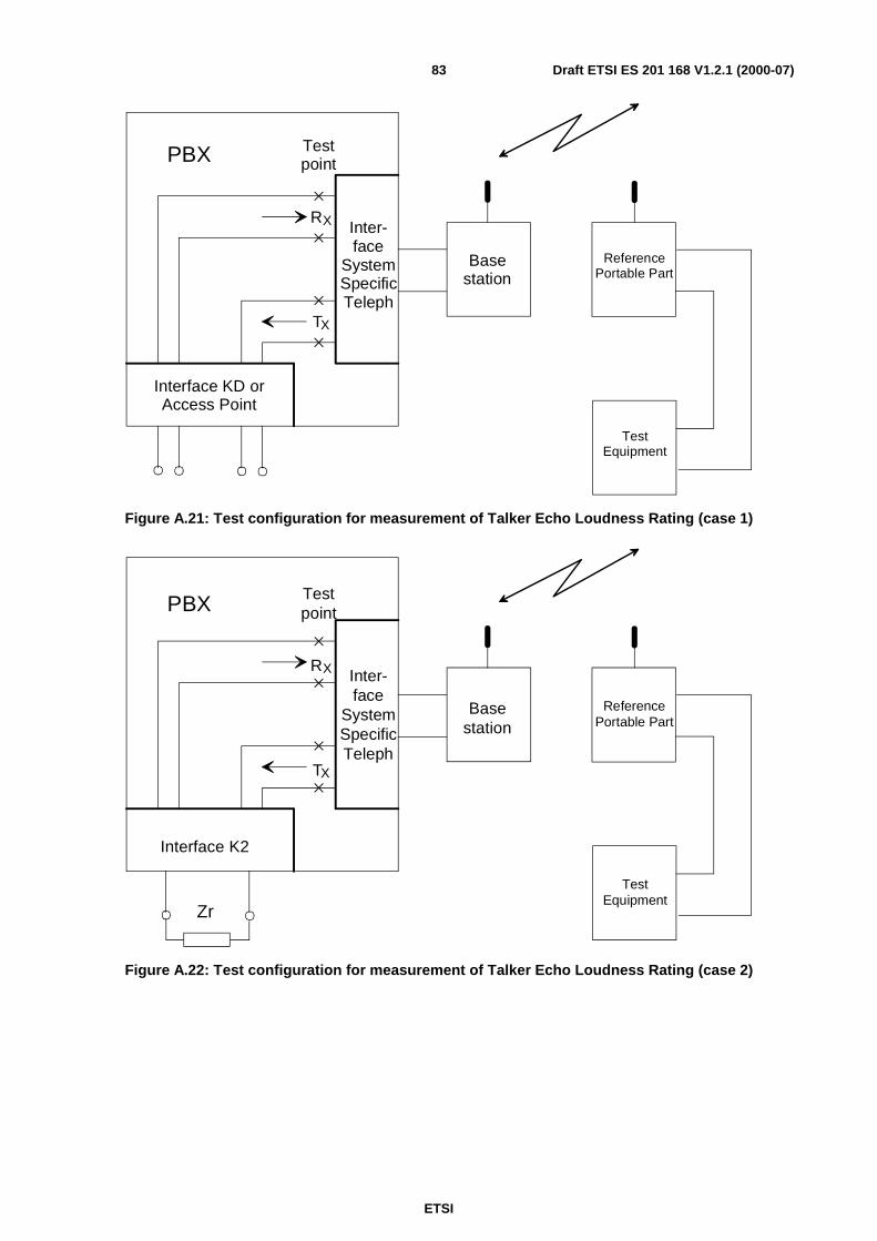
ETSI
Draft ETSI ES 201 168 V1.2.1 (2000-07)83
T
RX
X
TestpointPBX
Inter-face
SystemSpecificTeleph
Interface KD orAccess Point
Basestation
ReferencePortable Part
TestEquipment
Figure A.21: Test configuration for measurement of Talker Echo Loudness Rating (case 1)
T
RX
X
TestpointPBX
Inter-face
SystemSpecificTeleph
Interface K2
Basestation
ReferencePortable Part
TestEquipment
Zr
Figure A.22: Test configuration for measurement of Talker Echo Loudness Rating (case 2)
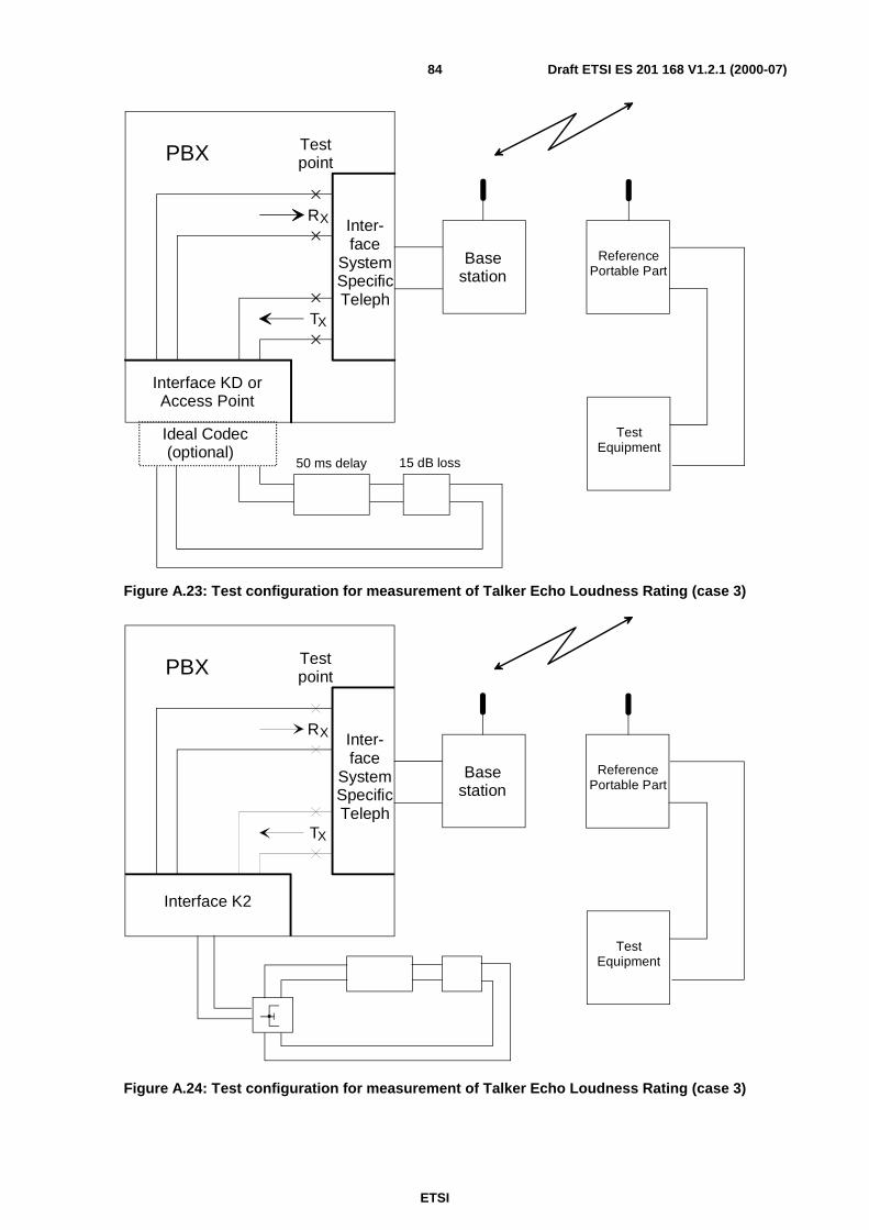
ETSI
Draft ETSI ES 201 168 V1.2.1 (2000-07)84
T
RX
X
TestpointPBX
Inter-face
SystemSpecificTeleph
Interface KD orAccess Point
Basestation
ReferencePortable Part
TestEquipment
Ideal Codec(optional)
50 ms delay 15 dB loss
Figure A.23: Test configuration for measurement of Talker Echo Loudness Rating (case 3)
T
RX
X
TestpointPBX
Inter-face
SystemSpecificTeleph
Interface K2
Basestation
ReferencePortable Part
TestEquipment
Figure A.24: Test configuration for measurement of Talker Echo Loudness Rating (case 3)
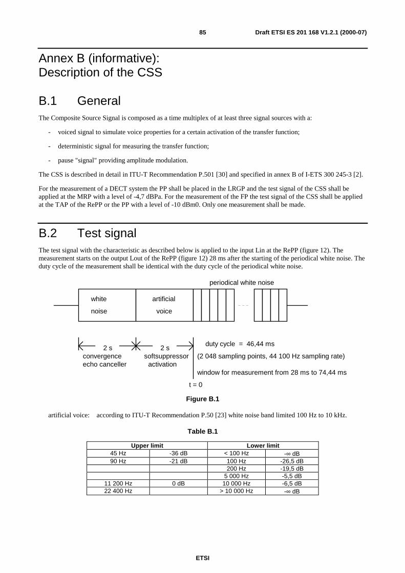
ETSI
Draft ETSI ES 201 168 V1.2.1 (2000-07)85
Annex B (informative):Description of the CSS
B.1 GeneralThe Composite Source Signal is composed as a time multiplex of at least three signal sources with a:
- voiced signal to simulate voice properties for a certain activation of the transfer function;
- deterministic signal for measuring the transfer function;
- pause "signal" providing amplitude modulation.
The CSS is described in detail in ITU-T Recommendation P.501 [30] and specified in annex B of I-ETS 300 245-3 [2].
For the measurement of a DECT system the PP shall be placed in the LRGP and the test signal of the CSS shall beapplied at the MRP with a level of -4,7 dBPa. For the measurement of the FP the test signal of the CSS shall be appliedat the TAP of the RePP or the PP with a level of -10 dBm0. Only one measurement shall be made.
B.2 Test signalThe test signal with the characteristic as described below is applied to the input Lin at the RePP (figure 12). Themeasurement starts on the output Lout of the RePP (figure 12) 28 ms after the starting of the periodical white noise. Theduty cycle of the measurement shall be identical with the duty cycle of the periodical white noise.
white
noise
artificial
voice
periodical white noise
2 s 2 sduty cycle = 46,44 ms
convergenceecho canceller
softsuppressoractivation
window for measurement from 28 ms to 74,44 ms
(2 048 sampling points, 44 100 Hz sampling rate)
t = 0
Figure B.1
artificial voice: according to ITU-T Recommendation P.50 [23] white noise band limited 100 Hz to 10 kHz.
Table B.1
Upper limit Lower limit45 Hz -36 dB < 100 Hz -∞ dB90 Hz -21 dB 100 Hz -26,5 dB
200 Hz -19,5 dB5 000 Hz -5,5 dB
11 200 Hz 0 dB 10 000 Hz -6,5 dB22 400 Hz > 10 000 Hz -∞ dB
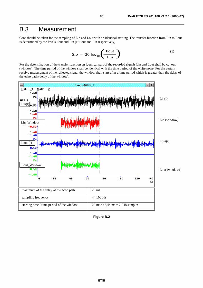
ETSI
Draft ETSI ES 201 168 V1.2.1 (2000-07)86
B.3 MeasurementCare should be taken for the sampling of Lin and Lout with an identical starting. The transfer function from Lin to Loutis determined by the levels Pout and Pin (at Lout and Lin respectively):
Sio = 20 log10
Pout
Pin
(1)
For the determination of the transfer function an identical part of the recorded signals Lin and Lout shall be cut out(window). The time period of the window shall be identical with the time period of the white noise. For the certainreceive measurement of the reflected signal the window shall start after a time period which is greater than the delay ofthe echo path (delay of the window).
Lin_Window
Lout_Window
Lout (t)Lout (t)
Lin(t)
Lin(t)
Lin (window)
Lout(t)
Lout (window)
maximum of the delay of the echo path 23 ms
sampling frequency 44 100 Hz
starting time / time period of the window 28 ms / 46,44 ms = 2 048 samples
Figure B.2
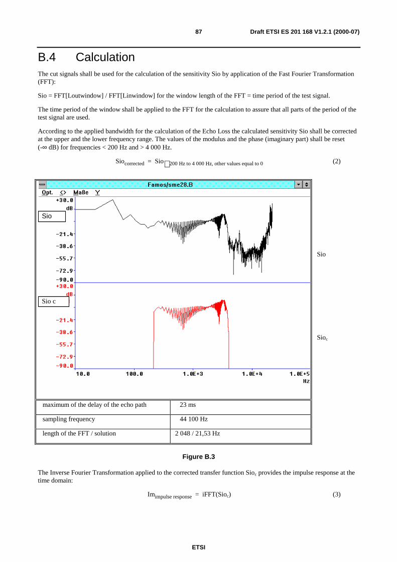
ETSI
Draft ETSI ES 201 168 V1.2.1 (2000-07)87
B.4 CalculationThe cut signals shall be used for the calculation of the sensitivity Sio by application of the Fast Fourier Transformation(FFT):
Sio = FFT[Loutwindow] / FFT[Linwindow] for the window length of the FFT = time period of the test signal.
The time period of the window shall be applied to the FFT for the calculation to assure that all parts of the period of thetest signal are used.
According to the applied bandwidth for the calculation of the Echo Loss the calculated sensitivity Sio shall be correctedat the upper and the lower frequency range. The values of the modulus and the phase (imaginary part) shall be reset(-∞ dB) for frequencies < 200 Hz and > 4 000 Hz.
Siocorrected = Sio 200 Hz to 4 000 Hz, other values equal to 0 (2)
Sio c
SioSio
Sio
Sioc
maximum of the delay of the echo path 23 ms
sampling frequency 44 100 Hz
length of the FFT / solution 2 048 / 21,53 Hz
Figure B.3
The Inverse Fourier Transformation applied to the corrected transfer function Sioc provides the impulse response at thetime domain:
Imimpulse response = iFFT(Sioc) (3)
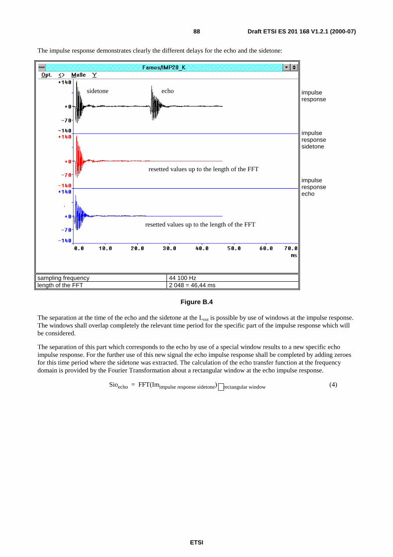
ETSI
Draft ETSI ES 201 168 V1.2.1 (2000-07)88
The impulse response demonstrates clearly the different delays for the echo and the sidetone:
sidetone echo
resetted values up to the length of the FFT
resetted values up to the length of the FFT
impulseresponse
impulseresponsesidetone
impulseresponseecho
sampling frequency 44 100 Hzlength of the FFT 2 048 = 46,44 ms
Figure B.4
The separation at the time of the echo and the sidetone at the Lout is possible by use of windows at the impulse response.The windows shall overlap completely the relevant time period for the specific part of the impulse response which willbe considered.
The separation of this part which corresponds to the echo by use of a special window results to a new specific echoimpulse response. For the further use of this new signal the echo impulse response shall be completed by adding zeroesfor this time period where the sidetone was extracted. The calculation of the echo transfer function at the frequencydomain is provided by the Fourier Transformation about a rectangular window at the echo impulse response.
Sioecho = FFT(Imimpulse response sidetone) rectangular window (4)
ETSI
Draft ETSI ES 201 168 V1.2.1 (2000-07)89
Annex C (informative):Bibliography
- ETSI I-ETS 300 003 (1991): "Business Telecommunications (BT); Transmission characteristics of digitalPrivate Automatic Branch Exchanges (PABXs)".
- ETSI I-ETS 300 004 (1991): "Business Telecommunications (BT); Transmission characteristics at 2-wireanalogue interfaces of a digital Private Automatic Branch Exchange (PABX)".
- ETSI I-ETS 300 005 (1991): "Business Telecommunications (BT); Transmission characteristics at 4-wireanalogue interfaces of a digital Private Automatic Branch Exchange (PABX)".
- ETSI I-ETS 300 006 (1991): "Business Telecommunications (BT); Transmission characteristics at digitalinterfaces of a digital Private Automatic Branch Exchange (PABX)".
ETSI ETS 300 439: "Business TeleCommunications (BTC); Transmission characteristics of digital PrivateBranch eXchanges (PBXs)".
ETSI ES 201 168 (V1.1.1): "Corporate telecommunication Networks (CN); Transmission characteristics ofdigital Private Branch eXchanges (PBXs)".
- ETSI ETR 250 (1996): "Transmission and Multiplexing (TM); Speech communication quality from mouth to earfor 3,1 kHz handset telephony across networks".
- ITU-T Recommendation G.100 (1993): "Definitions used in Recommendations on general characteristics ofinternational telephone connections and circuits".
- ITU-T Recommendation G.117 (1996): "Transmission aspects of unbalance about earth (definitions andmethods)".
- ETSI ETR 004 (1990): "Business Telecommunications (BT); Overall transmission plan aspects of a privatebranch network for voice connections with access to the public network".
- ITU-T Recommendation G.121 (03/93): Loudness ratings (LRs) of national systems.
- ITU-T Recommendation G.175 (09/99): Transmission planning for private/public network interconnection ofvoice traffic
- ITU-T Recommendation Q.45 bis (11/88): Transmission characteristics of an analogue international exchange.
- ITU-T Recommendation Q.554 (11/96): Transmission characteristics at digital interfaces of digital exchanges

ETSI
Draft ETSI ES 201 168 V1.2.1 (2000-07)90
History
Document history
V1.1.1 May 1998 Publication by EP CN
V1.2.1 July 2000 Membership Approval Procedure MV 20000908: 2000-07-11 to 2000-09-08