draft quantification protocol for landfill gas capture and...
TRANSCRIPT

Draft Quantification Protocol for Landfill Gas Capture and Combustion
Carbon Competitiveness Incentive Regulation
Draft Version 3.0
January 2018

Jan 2018 Draft Quantification Protocol for Landfill Gas Capture and Combustion Page 2 of 55 Draft Version 3.0 for Public Comment
© 2018 Government of Alberta
1 Disclaimer 2 3 This document is not a substitute for the legal requirements. Emission offset project developers must comply with 4 all applicable laws, including but not limited to those set out in the Climate Change and Emissions Management 5 Act (the Act), the Carbon Competitiveness Incentive Regulation (the Regulation), and Part 1 of the Standard for 6 Greenhouse Gas Emission Offset Project Developers (the Standard). 7 8 If there is a conflict between this quantification protocol and the Act, the Regulation or Part 1 of the Standard, the 9 Act, Regulation or Standard prevails over the quantification protocol. 10 11 All quantification protocols are subject to review as deemed necessary, and will be revised periodically to ensure 12 they reflect best available scientific knowledge and practices. For information regarding the withdrawal and 13 replacement of quantification protocols, see the Standard. 14
Title: Draft Quantification Protocol for Landfill Gas Capture and Combustion
Number: Draft Version 3.0 for Public Comment
Program Name: Alberta Emission Offset Program
Effective Date: TBD
This document was updated: January 2018

Jan 2018 Draft Quantification Protocol for Landfill Gas Capture and Combustion Page 3 of 55 Draft Version 3.0 for Public Comment
© 2018 Government of Alberta
Summary of Revisions 1
Version Date Summary of Revisions 3.0 January 2018 • The Protocol Scope was updated to exclude eligibility of the
displacement of emissions from fuels subject to the carbon levy under the Climate Leadership Act for generating emission offsets. Displacement of emissions from fuels with a carbon levy exemption certificate is an eligible activity under this protocol.
• The Baseline Condition was updated to quantify emissions from fossil fuel use for landfill gas capture and destruction for projects with applicable baseline conditions.
• The Quantification was updated by adding equations to quantify net reductions, offset-eligible reductions and levied emissions.
• The Quantification Methodology was updated to: o account for methane emissions from landfill gas combustion. o revise the quantification method to determine nitrous oxide emissions
from landfill gas combustion. o account for emissions from the combustion of fossil fuel used to
supplement the flare. • Standard conditions for gas quantification are now explicitly defined and
gas densities have been revised to align with standard conditions. • Appendix A was updated to differentiate the default destruction
efficiency for unassisted and steam/air assisted flares and to include methane densities at different reference temperatures.
2.0 July 2015 • The Protocol Flexibility mechanisms were reduced and modified. • Former flexibility mechanism 1 allowing project developers to use
alternative monitoring methodologies and/or equipment and flexibility mechanism 4 allowing the opportunity to generate emission offsets for upgrading an open flare to a controlled flare were removed.
• Former flexibility mechanism 2 allowing landfill gas to be sent to pipeline no longer requires the use of a flexibility mechanism.
• The Baseline Condition was updated to include oxidation of methane as it travels through the landfill cover and emissions associated with project fossil fuel use.
• The Project Condition was updated to use site-specific destruction efficiencies for combustion devices and include emissions from fossil fuel energy use.
• Project Sources and Sinks were updated to reflect current industry practice.
• The Quantification Methodology was clarified to provide for quantifying on-site and off-site heat and electricity generation and use.
• The protocol was updated to clarify Documents and Records requirements. The contingent data collection procedures were removed. Minimum data requirements specified in the protocol must be met.
1.0 September 2007
Quantification Protocol for Landfill Gas Capture and Combustion was published for use in the Alberta carbon offset system.

Jan 2018 Draft Quantification Protocol for Landfill Gas Capture and Combustion Page 4 of 55 Draft Version 3.0 for Public Comment
© 2018 Government of Alberta
Table of Contents 1 Summary of Revisions ............................................................................................................................................... 2 2 Related Publications ................................................................................................................................................... 4 3 1.0 Offset Project Description .................................................................................................................. 6 4
1.1 Protocol Scope ................................................................................................................................... 6 5 1.2 Protocol Applicability ........................................................................................................................ 8 6 1.3 Protocol Flexibility ............................................................................................................................ 8 7 1.4 Glossary of Terms .............................................................................................................................. 8 8
2.0 Baseline Condition ........................................................................................................................... 10 9 2.1 Identification of Baseline Sources and Sinks ................................................................................... 12 10
3.0 Project Condition ............................................................................................................................. 17 11 3.1 Identification of Project Sources and Sinks ..................................................................................... 19 12
4.0 Quantification................................................................................................................................... 24 13 4.1 Quantification Methodology ............................................................................................................ 30 14 4.1.1 Net Emission Reductions ................................................................................................................. 30 15 4.1.2 Offset Eligible Reductions ............................................................................................................... 30 16 4.1.3 Levied Fuel Emissions (reported but not included in offset calculation) ........................................ 31 17
5.0 Documents and Records ................................................................................................................... 51 18 5.1 Documents ....................................................................................................................................... 51 19 5.2 Records ............................................................................................................................................ 52 20 5.3 Quality Assurance/Quality Control Considerations ......................................................................... 53 21 5.4 Liability ............................................................................................................................................ 54 22
23 List of Appendices 24 Appendix A: Quantification Parameters………………………………………………………………………...........…55 25 26 List of Tables 27 Table 1: Eligible Project Scenarios ............................................................................................................................ 7 28 Table 2: Baseline Sources and Sinks ........................................................................................................................ 14 29 Table 3: Project Condition Sources and Sinks ......................................................................................................... 21 30 Table 4: Comparison of Sources and Sinks .............................................................................................................. 25 31 Table 5: Quantification Methodology ...................................................................................................................... 32 32 Table 6: Examples of Documents Required to Meet Offset Criteria ........................................................................ 52 33 Table 7: Record Requirements and Examples of Records ....................................................................................... 52 34 Table A1: Default Values for Methane Destruction Efficiency (USEPA)…………………………………...…………52 35 Table A2: Density of CH4 at 1 atm/101.325 kPa……………………………………………………………….........…54 36 37 List of Figures 38 Figure 1: General Representation of the Baseline and Project Conditions................................................................. 7 39 Figure 2: Simplified Process Flow Diagram for Possible Baseline Conditions ....................................................... 11 40 Figure 3: Baseline Sources and Sinks for Landfill Gas Capture and Combustion ................................................... 13 41 Figure 4: Simplified Process Flow Diagram for Possible Project Condition ........................................................... 18 42 Figure 5: Project Conditions Sources and Sinks for Landfill Gas Capture and Combustion ................................... 20 43 44
45

Jan 2018 Draft Quantification Protocol for Landfill Gas Capture and Combustion Page 5 of 55 Draft Version 3.0 for Public Comment
© 2018 Government of Alberta
Alberta Climate Change Office Related Publications 1 2
• Climate Leadership Act 3 • Climate Leadership Regulation 4 • Carbon Competitiveness Incentive Regulation 5 • Climate Change and Emissions Management Act 6 • Environmental Protection and Enhancement Act 7 • Specified Gas Emitters Regulation 8 • Technical Guidance for Greenhouse Gas Verification at Reasonable Level Assurance 9 • Technical Guidance for Offset Project Developers 10 • Technical Guidance for Offset Protocol Developers 11 • Carbon Offset Emission Factors Handbook 12 • Standard for Greenhouse Gas Emission Offset Project Developers 13 • Standard for Greenhouse Gas Verification 14 • Waste Control Regulation 15 • Code of Practice for Landfills 16
17 18
Jan 2018 Draft Quantification Protocol for Landfill Gas Capture and Combustion Page 6 of 55 Draft Version 3.0 for Public Comment
© 2018 Government of Alberta
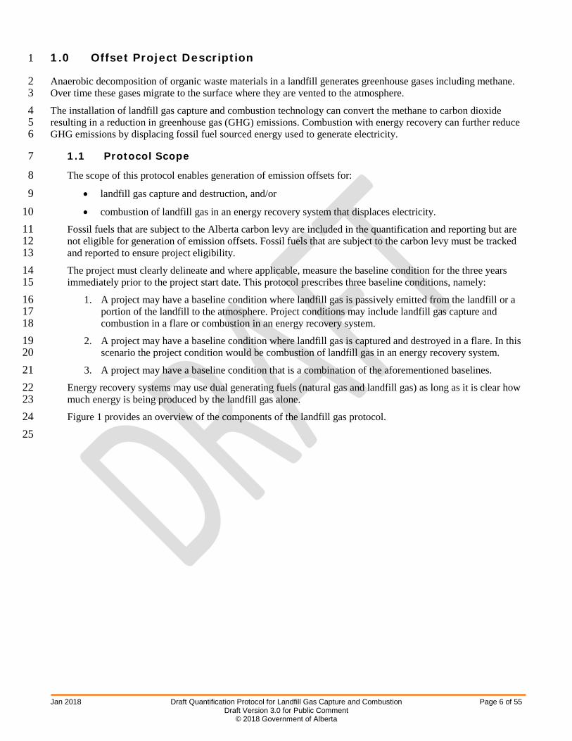
1.0 Offset Project Description 1
Anaerobic decomposition of organic waste materials in a landfill generates greenhouse gases including methane. 2 Over time these gases migrate to the surface where they are vented to the atmosphere. 3 The installation of landfill gas capture and combustion technology can convert the methane to carbon dioxide 4 resulting in a reduction in greenhouse gas (GHG) emissions. Combustion with energy recovery can further reduce 5 GHG emissions by displacing fossil fuel sourced energy used to generate electricity. 6
1.1 Protocol Scope 7
The scope of this protocol enables generation of emission offsets for: 8 • landfill gas capture and destruction, and/or 9 • combustion of landfill gas in an energy recovery system that displaces electricity. 10
Fossil fuels that are subject to the Alberta carbon levy are included in the quantification and reporting but are 11 not eligible for generation of emission offsets. Fossil fuels that are subject to the carbon levy must be tracked 12 and reported to ensure project eligibility. 13 The project must clearly delineate and where applicable, measure the baseline condition for the three years 14 immediately prior to the project start date. This protocol prescribes three baseline conditions, namely: 15
1. A project may have a baseline condition where landfill gas is passively emitted from the landfill or a 16 portion of the landfill to the atmosphere. Project conditions may include landfill gas capture and 17 combustion in a flare or combustion in an energy recovery system. 18
2. A project may have a baseline condition where landfill gas is captured and destroyed in a flare. In this 19 scenario the project condition would be combustion of landfill gas in an energy recovery system. 20
3. A project may have a baseline condition that is a combination of the aforementioned baselines. 21 Energy recovery systems may use dual generating fuels (natural gas and landfill gas) as long as it is clear how 22 much energy is being produced by the landfill gas alone. 23 Figure 1 provides an overview of the components of the landfill gas protocol. 24
25

Jan 2018 Draft Quantification Protocol for Landfill Gas Capture and Combustion Page 7 of 55 Draft Version 3.0 for Public Comment
© 2018 Government of Alberta
Figure 1: General Representation of the Baseline and Project Conditions 1 2 3 4 5 6 7 8 9 10 11 12 13
14
Eligible project conditions include the following: 15 • Projects must install a landfill gas capture and controlled combustion system; 16 • Projects may either combust landfill gas to displace fossil fuel sourced for heat and/or electricity or 17
destroy the landfill gas in a flare (if there was no flaring in the baseline condition); 18 • Landfill facilities must meet Alberta Environment and Park’s registration and approval authorization 19
requirements; and 20 • The project cannot adversely affect other waste diversion initiatives. 21
22 Three project scenarios are eligible under this protocol as indicated in Table 1. 23 Table 1: Eligible Project Scenarios 24
Baseline Scenarios
Baseline Project
Emissions Fossil Fuel Use Methane Surface
Oxidation
Methane Destruction
Energy Recovery
Passive venting of
LFG to atmosphere
CH4 If project condition displaces fossil fuel energy generation
Yes Yes Yes or No
LFG combustion in
a flare
CO2, Trace
CH4, N2O Yes No Yes Yes
Combination of two
scenarios
CO2, CH4, N2O
Yes Yes Yes Yes
LFG is landfill gas. 25 This protocol does not estimate or quantify the total GHG emissions from a landfill. Rather, the GHG 26 calculation is based on the measured volume and composition of landfill gas collected and combusted. The 27 greenhouse gases affected by the activities described in this protocol include methane (CH4), carbon dioxide 28
Baseline
Fugitive Emissions from
Landfill
Fossil Fuel-Sourced Energy
Project
Landfill Gas Capture
Landfill Gas Use for Electricity or Heat Generation
Landfill Gas Destruction in a
Flare Emissions from Flaring (if applicable)

Jan 2018 Draft Quantification Protocol for Landfill Gas Capture and Combustion Page 8 of 55 Draft Version 3.0 for Public Comment
© 2018 Government of Alberta
(CO2) and nitrous oxide (N2O). The applicable Global Warming Potential (GWP) for each gas is available in 1 the Carbon Offset Emission Factors Handbook. 2
1.2 Protocol Applicability 3
Project developers must be able to demonstrate the offset project meets the requirements of the Carbon 4 Competitiveness Incentive Regulation, published documents or standards for the Alberta emission offset 5 system and this quantification protocol. 6 In particular, the project developer must provide sufficient evidence to demonstrate that: 7
1. The combustion is carried out under controlled conditions as demonstrated by a description of the 8 landfill gas (LFG) end use and specifications of the combustion device in use; 9
2. Combustion efficiencies from flares or other combustion equipment must be site-specific when site-10 specific information is available; 11
3. If applicable, the energy produced from landfill gas is offsetting fossil fuel-generated energy in the 12 form of heat and/or electricity; 13
4. Metering of gas volume takes place downstream from capture within a reasonable distance of either 14 the combustion device such that the meter will account for the potential for fugitive emissions as 15 demonstrated by project schematics; 16
5. Reductions achieved by the project are based on actual measurement and monitoring, as per this 17 protocol; and, 18
6. This protocol does not include emission offset eligibility for the displacement of emissions from fuels 19 subject to the carbon levy. It is still a requirement to quantify these emissions with a reasonable level 20 of assurance. However, displacement of emissions from fuels subject to the carbon levy may be 21 eligible for consideration under this protocol with a carbon levy exemption certificate under the 22 Climate Leadership Act. 23 24
1.3 Protocol Flexibility 25 26 The protocol prescribes using site-specific landfill gas destruction efficiencies as they result in higher 27 accuracy relative to using generic destruction efficiencies. Flexibility is allowed through the use of the generic 28 emission factors listed in the Carbon Offset Emissions Factors Handbook where there is insufficient 29 information to support site-specific landfill gas destruction efficiencies for quantification. Justification for use 30 of the generic emission factor must be provided in the project plan. 31
32 1.4 Glossary of Terms 33
34
Anaerobic Decomposition
A biological process in which bacteria break the organic matter down in the absence of oxygen.
Cogeneration The combined production of heat and electricity for use in industrial facilities. Electricity not used within the plant may be offered to the competitive electricity market.
Combustion The oxidation of fuel/biomass that forms water and carbon dioxide in an exothermic reaction.

Jan 2018 Draft Quantification Protocol for Landfill Gas Capture and Combustion Page 9 of 55 Draft Version 3.0 for Public Comment
© 2018 Government of Alberta
Destruction Efficiency
The efficiency of the combustion device in oxidizing the methane to carbon dioxide.
Heat The useful thermal energy that is generated in a heat generation plant (e.g., a boiler, a cogeneration unit, thermal solar panels, etc.) and transferred to a heat carrier (e.g., hot liquids, hot gases, steam, etc.) for use in thermal applications and processes, including electricity generation but excluding waste heat.
Landfill A waste management facility for the intentional placement of waste on or in land as the waste’s final resting place (as per section 2(1)(i) of the Environmental Protection and Enhancement Act Activities Designation Regulation).
Landfill Gas (LFG) Gas resulting from the decomposition of organic wastes placed in a landfill comprised primarily of methane, carbon dioxide, and other trace compounds.
Methanotrophic Bacteria Bacteria that is able to metabolize methane for energy.
Municipal Solid Waste (MSW)
Non-hazardous waste materials picked up by a municipality or self-hauled to depots, transfer stations and disposal facilities. Municipal solid waste is composed of residential and non-residential materials from construction, renovation, and demolition or commercial and institutional waste.
Oxidation The process that results when methanotrophic bacteria metabolize methane to carbon dioxide under aerobic conditions.
Standard temperature and pressure
Standard conditions are defined to be 15 °C and 101.325 kPa (1 atm).
Waste Any solid or liquid material or combination that is or is intended to be treated or disposed of or that is intended to be stored and then treated or disposed of, but does not include recyclables.
Waste Management Facility
A facility registered under the Alberta Code of Practice for Landfills or approved under Alberta’s Environmental Protection and Enhancement Act or other legislation for the collection, storage, treatment or disposal of waste. In Alberta, all waste must be disposed in a waste management facility.
1

Jan 2018 Draft Quantification Protocol for Landfill Gas Capture and Combustion Page 10 of 55 Draft Version 3.0 for Public Comment
© 2018 Government of Alberta
2.0 Baseline Condition 1
The baseline is the most appropriate and best estimate of GHG emissions that would have occurred in the absence 2 of the project. The three baseline conditions that exist for this activity are: 3
1. Landfill gas that is passively vented to atmosphere 4 2. Landfill gas that is combusted in a flare; or 5 3. A combination of the two above scenarios. 6
Emissions associated with heat and electricity generation, as well as on- and off-site energy, are quantified 7 separately to ensure that the appropriate emission factors are used. 8 The protocol uses a dynamic, projection-based baseline for quantifying avoided landfill methane emissions. That 9 is, baseline landfill gas emissions are projected based on the volume of landfill gas combusted in the project 10 condition with application of a methane oxidation factor to account for oxidation of methane by methanotropic 11 bacteria as it passes through the landfill cover. Baseline fossil fuel use is calculated based on the net energy 12 generation in the project and fossil fuel use in the baseline and project conditions. In baseline scenarios which 13 include flaring or partial flaring of landfill gas, three years of records are required to support the extent of landfill 14 gas flaring when determining the baseline condition. 15 The baseline GHG emissions are then calculated annually based on the net amount of landfill gas sourced energy 16 generated in the project condition and the equivalent volume of fossil fuels that would have been used to meet the 17 same energy needs in the absence of the project. Projects cannot claim for generated energy that is not being 18 used. 19 A simplified process flow diagram for possible baseline conditions is shown in Figure 2. More detail on each of 20 these sources/sinks is provided in Section 2.1. 21
22

Jan 2018 Draft Quantification Protocol for Landfill Gas Capture and Combustion Page 11 of 55 Draft Version 3.0 for Public Comment
© 2018 Government of Alberta
Figure 2: Simplified Process Flow Diagram for Possible Baseline Conditions
Waste Generation
Waste Collection &
Transportation
Waste Processing
Waste Disposal Waste Decomposition
Waste Diversion Projects
On-site Fossil Fuel Sourced Electricity
and/or Heat
Off-site Fossil Fuel Sourced
Electricity and/or Heat
Landfill Gas Capture and
Flaring

Jan 2018 Draft Quantification Protocol for Landfill Gas Capture and Combustion Page 12 of 55 Draft Version 3.0 for Public Comment
© 2018 Government of Alberta
2.1 Identification of Baseline Sources and Sinks
The identification of sources and sinks in the baseline condition is based on ISO 14064-2:20061: Specification with guidance at the project level for quantification, monitoring and reporting of greenhouse gas emission reductions or removal enhancements. Sources and sinks are determined to be either controlled, related or affected by the project and are defined as follows:
Controlled: The behaviour or operation of a controlled source and/or sink is under the direction and influence of a project developer through financial, policy, management or other instruments.
Related: A related source and/or sink has material and/or energy flows into, out of or within a project but is not under the reasonable control of the project developer.
Affected: An affected source and/or sink is influenced by the project activity through changes in market demand or supply for projects or services associated with the project.
All sources and sinks were identified by reviewing the relevant process flow diagrams, consulting with technical experts and reviewing best practice guidance. This iterative process confirmed that sources/sinks in the process flow diagrams covered the full scope of eligible activities under this protocol.
Based on the process flow diagram provided, the baseline sources/sinks were organized into life cycle categories as provided in Figure 3. A description of each source/sink and its classification as controlled, related or affected is provided in Table 2.
1International Organization for Standardization. 2006. ISO 14064-2: Specification with guidance at the project level for quantification, monitoring and reporting of greenhouse gas emission reductions or removal enhancements.

Jan 2018 Draft Quantification Protocol for Landfill Gas Capture and Combustion Page 13 of 55 Draft Version 3.0 for Public Comment
© 2018 Government of Alberta
Figure 3: Baseline Sources and Sinks for Landfill Gas Capture and Combustion
Downstream Sources / Sinks During Baseline
Affected Source/Sink
Upstream Sources/Sinks Before Baseline
Legend
On-Site Sources/Sinks During Baseline
Downstream Sources/Sinks During Baseline
Related Source/Sink
Controlled Source/Sink
Upstream Sources/Sinks During Baseline
B3 Waste Handling and
Disposal
B4 Fuel Extraction and
Processing
B5 Fuel Delivery
B18 Site Decommissioning
B1 Waste Generation
B15 On-site Heat
Generation Displaced in Project
B2 Waste Collection
and Transportation
B13 Waste Decomposition
B6 Off-site Electricity
Generation Displaced by Project
B8 Site Development
B7 Off-site Heat
Generation Displaced in Project
B9 Building Equipment
B19 Off-site Heat and
Electricity Not Displaced in Project
B11 Construction On Site
B10 Transportation of
Equipment
B12 Testing of
Equipment
B17 Waste Diversion
B16 On-site Heat and
Electricity Generation Not Displaced in
Project
B20 Supplemental Fossil Fuel Use Needed for
Flaring
B22 Fossil Fuel Use
B21 Landfill Gas Combustion
B14 On-site Electricity
Generation Displaced by Project

Jan 2018 Draft Quantification Protocol for Landfill Gas Capture and Combustion Page 14 of 55 Draft Version 3.0 for Public Comment
© 2018 Government of Alberta
Table 2: Baseline Sources and Sinks
Sources/Sinks Description Controlled, Affected, Related
Upstream Sources and Sinks Before Baseline
B8 - Site Development Baseline site development could include: civil infrastructure such as access to electricity, natural gas and water supply, sewer, etc; clearing, grading, building access roads, etc; and building of structures for the facility such as storage areas and offices, and structures to enclose, support and house any equipment. Greenhouse gas emissions would be primarily attributed to the use of fossil fuels and electricity used to power equipment required to develop the site including, but not limited to graders, backhoes, trenching machines, etc.
Related
B9 - Building Equipment
Equipment may need to be built either on site or off site. This includes all of the components of the storage, handling, processing, combustion, air quality control, system control and safety systems. These may be sourced as pre-made standard equipment or custom built to specification. Greenhouse gas emissions would be primarily attributed to the use of fossil fuels and electricity used to power equipment for the extraction of the raw materials, processing, fabrication and assembly.
Related
B10 -Transportation of Equipment
Equipment built off site and the materials to build equipment on site need to be delivered to the site. Transportation may be completed by train, truck or other transportation. Greenhouse gas emissions are primarily attributed to the use of fossil fuels for transportation.
Related
B11 - Construction On Site
Site construction uses a variety of heavy equipment, smaller power tools, cranes and generators. The operation of this equipment has associated greenhouse gas emission from the use of fossil fuels and electricity.
Related
B12 - Testing of Equipment
Equipment may need to be tested to ensure that it is operational. This may result in running the equipment using test anaerobic digestion fuels or fossil fuels in order to ensure that the equipment runs properly. These activities result in greenhouse gas emissions associated with the combustion of the test fuels and the use of electricity.
Related
Upstream Sources and Sinks During Baseline
B1 - Waste Generation Waste is generated when post-consumer and other wastes are discarded for permanent disposal in a landfill.
Related
B2 - Waste Collection and Transportation
Solid waste may be transported to the project site by truck and/or train. The related energy inputs for fuelling this equipment are captured under this source/sink. Type of equipment, number of loads and distance traveled would be used to evaluate functional equivalence with the project condition.
Related
B3 - Waste Handling and Disposal
Waste may be handled at a disposal site by transferring the waste from the transportation container, spreading, burying, processing, and otherwise dealing with the waste using a combination of loaders,
Controlled

Jan 2018 Draft Quantification Protocol for Landfill Gas Capture and Combustion Page 15 of 55 Draft Version 3.0 for Public Comment
© 2018 Government of Alberta
Sources/Sinks Description Controlled, Affected, Related
conveyors and other mechanized devices. Greenhouse gas emissions result from the combustion of fossil fuel to operate the equipment. Volumes and types of fuels must be tracked.
B4 - Fuel Extraction and Processing
Greenhouse gas emissions are associated with fossil fuel extraction and processing. Emissions are attributed to the various processes involved in the production, refinement and storage of the fuels. The total volumes of fuel for each of the on-site sources/sinks are considered under this source/sink. Volumes and types of fuels must be tracked.
Related
B5 - Fuel Delivery This source/sink accounts for emissions associated with transporting each of the fuels used on site to the site. This may include shipment by truck, rail or pipeline. Fuel sourced by taking equipment to an existing commercial fuelling station is excluded as the fuel used to take the equipment to the site is captured under other source/sinks.
Related
B6 –Off-site Electricity Generation Displaced by Project
Emissions associated with generation of electricity off-site which have been displaced through the project activity. This occurs either through the export of electricity off site and/or reduced import of grid electricity.
Controlled
B7 – Off-site Heat Generation Displaced in Project
Emissions associated with generation of heat off site which have been displaced through the project activity. This occurs through the export of heat off site and/or reduced import of heat that was generated off site.
Controlled
B19 - Off-site Heat and Electricity Not Displaced in Project
The remainder of off-site emissions associated with heat and electricity generation which has not been displaced in the project condition.
Related
On-site Sources and Sinks During Baseline
B13 – Waste Decomposition
This source/sink is applicable for projects that passively vent landfill gas to the atmosphere in the baseline condition. Waste decomposing in the disposal facility results in the production of methane. GHG emissions from waste decomposition are accounted by measuring the volume of landfill gas collected and combusted to determine the amount of landfill gas that would have been released in the absence of an operating landfill gas capture system. A methane oxidation factor is applied to account for oxidation of methane by methanotrophic bacteria as methane travels through the landfill cover system.
Controlled
B14 – On-site Electricity Generation Displaced by the Project
This source represents the emissions from on-site generation that occurred in the baseline that would have been replaced by the project. This could be all or part of the historic electricity generation onsite. The emissions from this source are calculated using site specific emission factors.
Controlled
Jan 2018 Draft Quantification Protocol for Landfill Gas Capture and Combustion Page 16 of 55 Draft Version 3.0 for Public Comment
© 2018 Government of Alberta
Sources/Sinks Description Controlled, Affected, Related
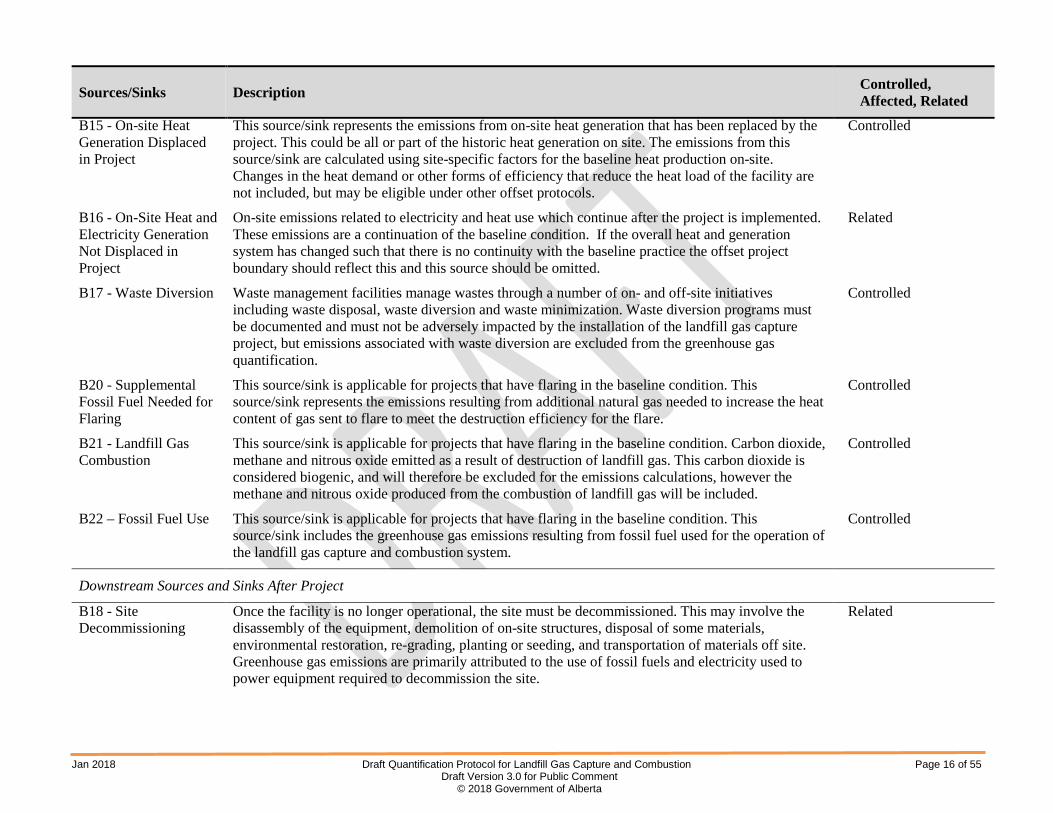
B15 - On-site Heat Generation Displaced in Project
This source/sink represents the emissions from on-site heat generation that has been replaced by the project. This could be all or part of the historic heat generation on site. The emissions from this source/sink are calculated using site-specific factors for the baseline heat production on-site. Changes in the heat demand or other forms of efficiency that reduce the heat load of the facility are not included, but may be eligible under other offset protocols.
Controlled
B16 - On-Site Heat and Electricity Generation Not Displaced in Project
On-site emissions related to electricity and heat use which continue after the project is implemented. These emissions are a continuation of the baseline condition. If the overall heat and generation system has changed such that there is no continuity with the baseline practice the offset project boundary should reflect this and this source should be omitted.
Related
B17 - Waste Diversion Waste management facilities manage wastes through a number of on- and off-site initiatives including waste disposal, waste diversion and waste minimization. Waste diversion programs must be documented and must not be adversely impacted by the installation of the landfill gas capture project, but emissions associated with waste diversion are excluded from the greenhouse gas quantification.
Controlled
B20 - Supplemental Fossil Fuel Needed for Flaring
This source/sink is applicable for projects that have flaring in the baseline condition. This source/sink represents the emissions resulting from additional natural gas needed to increase the heat content of gas sent to flare to meet the destruction efficiency for the flare.
Controlled
B21 - Landfill Gas Combustion
This source/sink is applicable for projects that have flaring in the baseline condition. Carbon dioxide, methane and nitrous oxide emitted as a result of destruction of landfill gas. This carbon dioxide is considered biogenic, and will therefore be excluded for the emissions calculations, however the methane and nitrous oxide produced from the combustion of landfill gas will be included.
Controlled
B22 – Fossil Fuel Use This source/sink is applicable for projects that have flaring in the baseline condition. This source/sink includes the greenhouse gas emissions resulting from fossil fuel used for the operation of the landfill gas capture and combustion system.
Controlled
Downstream Sources and Sinks After Project
B18 - Site Decommissioning
Once the facility is no longer operational, the site must be decommissioned. This may involve the disassembly of the equipment, demolition of on-site structures, disposal of some materials, environmental restoration, re-grading, planting or seeding, and transportation of materials off site. Greenhouse gas emissions are primarily attributed to the use of fossil fuels and electricity used to power equipment required to decommission the site.
Related

Jan 2018 Draft Quantification Protocol for Landfill Gas Capture and Combustion Page 17 of 55 Draft Version 3.0 for Public Comment
© 2018 Government of Alberta
3.0 Project Condition
The project condition is the capture and combustion of landfill gas in a flare or for energy generation. GHG emission reductions are achieved through the destruction of methane and, if applicable, the displacement of fossil fuel energy. Projects that were passively venting methane in the baseline can destroy landfill gas in a flare or combust the gas for energy generation. Projects that were capturing and combusting landfill gas in the baseline in a flare, may implement an energy recovery project and qualify for emission offsets from the energy displacement.
In all cases, the destruction efficiency provided by the manufacturer must be used. If the device has no destruction efficiency, the project proponent must reference default destruction efficiencies from Table A1: Default Values for Methane Destruction Efficiency to quantify greenhouse gas emission reductions for landfill gas combustion. Justification for using the default destruction efficiency in Table A1 must be provided.
A process flow diagram for the project condition is provided in Figure 4. More detail on each of these sources/sinks is provided in Section 3.1.

Jan 2018 Draft Quantification Protocol for Landfill Gas Capture and Combustion Page 18 of 55 Draft Version 3.0 for Public Comment
© 2018 Government of Alberta
Figure 4: Simplified Process Flow Diagram for Possible Project Condition
Upset Flaring
Waste Generation
Waste Collection and Transportation
Waste Handling
Waste Disposal
Waste Decomposition
LFG Capture
LFG Processing
Heat Generation and Use
Processing for Distribution in a
Pipeline
Flaring
Natural Gas Use
Electricity Generation and
Use

Jan 2018 Draft Quantification Protocol for Landfill Gas Capture and Combustion Page 19 of 55 Draft Version 3.0 for Public Comment
© 2018 Government of Alberta
3.1 Identification of Project Sources and Sinks
Figure 5 provides a list of sources and sinks associated with landfill gas capture and combustion projects. All included sources and sinks applicable to the project must be identified in the project plan. If a source or sink is not applicable to the project, sufficient justification must be provided to support the exclusion.
Based on the process flow diagram provided in Figure 4, the project sources and sinks were organized into life cycle categories as provided in Figure 5. Descriptions of each of the sources and sinks and their classification as controlled, related or affected are provided in Table 3.

Jan 2018 Draft Quantification Protocol for Landfill Gas Capture and Combustion Page 20 of 55 Draft Version 3.0 for Public Comment
© 2018 Government of Alberta
Figure 5: Project Conditions Sources and Sinks for Landfill Gas Capture and Combustion
P16 Landfill Gas Combustion
P17 Site Decommissioning
P7 Site Development
P8 Building Equipment
P10 Construction On Site
P9 Transportation of
Equipment
P11 Testing of
Equipment
Upstream Sources / Sinks During Project
Upstream Sources / Sinks Before Project On-site Sources / Sinks During Project
Downstream Sources / Sinks After Project
Downstream Sources / Sinks During Project
Affected Source/Sink
Legend
Related Source/Sink
Controlled Source/Sink
P3 Waste Handling and
Disposal
P6 Off-site Heat and
Electricity Not Displaced
P4 Fuel Extraction and
Processing
P5 Fuel Delivery
P1 Waste Generation
P2 Waste Collection and
Transportation
P12 Fossil Fuel Use
P13 Supplemental Fossil
Fuel Needed for Flaring
P15 Waste Diversion
P14 On-site Heat and
Electricity Not Displaced in Project

Jan 2018 Draft Quantification Protocol for Landfill Gas Capture and Combustion Page 21 of 55 Draft Version 3.0 for Public Comment
© 2018 Government of Alberta
Table 3: Project Condition Sources and Sinks
Sources/Sinks Description Controlled, Affected, Related
Upstream Sources and Sinks
P7 - Site Development
Greenhouse gas emissions associated with site preparation and development for the landfill gas capture and combustion system results are associated with preparing civil infrastructure such as access to electricity, natural gas, water supply, sewer, clearing, grading, building access roads, construction of structures for the facility such as storage areas, storm water drainage, offices, vent stacks, firefighting water storage lagoons, and enclose, support and house the equipment.
Related
P8 - Building Equipment
New equipment may need to be built, either on or off site. This includes all of the components of the new system, including, but not limited to, storage, handling, processing, combustion, air system controls and safety systems. These may be sourced as pre-made standard equipment or custom built to specification. These activities generate greenhouse gas emissions from the use of fossil fuels and electricity to power equipment for the extraction of the raw materials, processing, fabricating and assembly.
Related
P9 - Transportation of Equipment
Greenhouse gas emissions are associated with fuel combustion to transport equipment and materials to the site. Transportation may be completed by train, truck or combination.
Related
P10 - Construction On Site
Greenhouse gas emissions are associated with the use fossil fuels and electricity to power heavy equipment, smaller power tools, cranes and generators used to construct the site.
Related
P11 - Testing of Equipment
Equipment may need to be tested to ensure that it is operational. This may result in running the equipment using test anaerobic digestion fuels or fossil fuels in order to ensure that the equipment runs properly. These activities will result in greenhouse gas emissions associated with the combustion of fossil fuels and the use of electricity.
Related
Upstream Sources and Sinks During Project
P1 - Waste Generation
Waste is generated when post-consumer and other wastes are sent discarded for permanent disposal in a landfill.
Related
P2 - Waste Collection and Transportation
Solid waste may be transported to the project site by truck and/or train. The related energy inputs for fuelling this equipment are captured under this source/sink. Type of equipment, number of loads and distance traveled would be used to evaluate functional equivalence with the baseline condition.
Related
P3 - Waste Handling and Disposal
Waste may be handled at a disposal site by transferring the waste from the transportation container, spreading, burying, processing or otherwise dealing with the waste using a combination of loaders, conveyors and other mechanized devices. Greenhouse gas emissions result from the combustion of fossil fuel to operate the equipment. Volumes and types of fuels must be tracked.
Controlled

Jan 2018 Draft Quantification Protocol for Landfill Gas Capture and Combustion Page 22 of 55 Draft Version 3.0 for Public Comment
© 2018 Government of Alberta
Sources/Sinks Description Controlled, Affected, Related
P4 - Fuel Extraction and Processing
Greenhouse gas emissions are associated with fossil fuel extraction and processing. Emissions are attributed to the various processes involved in the production, refinement, and storage of the fuels. The total volumes of fuel for each of the on-site sources/sinks are considered under this source/sink. Volumes and types of fuels must be tracked.
Related
P5 - Fuel Delivery This source/sink accounts for emissions associated with transporting each of the fuels used on site to the site. This may include shipment by truck, rail or pipeline. Fuel sourced by taking equipment to an existing commercial fuelling station is excluded as the fuel used to take the equipment to the site is captured under other source/sinks.
Related
P6 - Off-site Heat and Electricity Not Displaced
Emissions associated with off-site electricity and heat generation that has not been displaced by the project activity.
Related
On-site Sources and Sinks During Project
P12 - Fossil Fuel Use
This source/sink includes the greenhouse gas emissions resulting from fossil fuel used for the operation of the landfill gas capture and combustion system.This may also include emissions associated with upgrading of landfill gas for flare.
Controlled
P13 - Suppemental Fossil Fuel Needed for Flaring
This represents the emissions resulting from additional natural gas needed to increase the heat content of gas sent to flare to meet the destruction efficiency for the flare.
Controlled
P14 – On-site Heat and Electricity Not Displaced
The emissions associated with pre-existing and non-project related on-site heat and electricity generation that have not been displaced by heat or electricity produced by the project.
Controlled
P15 - Waste Diversion
Waste management facilities manage wastes through a number of on- and off-site initiatives including waste disposal, waste diversion and waste minimization. Waste diversion programs must be documented, and must not be adversely impacted by the installation of the landfill gas capture project, but emissions associated with waste diversion are excluded from the greenhouse gas quantification.
Controlled
P16 – Landfill Gas Combustion
Carbon dioxide, methane and nitrous oxide emitted as a result of destruction of landfill gas. This CO2 is considered biogenic, and will therefore be excluded for the emissions calculations, however the methane and nitrous oxide produced from the destruction of landfill gas will be included.
Controlled
Downstream Sources and Sinks After Project

Jan 2018 Draft Quantification Protocol for Landfill Gas Capture and Combustion Page 23 of 55 Draft Version 3.0 for Public Comment
© 2018 Government of Alberta
Sources/Sinks Description Controlled, Affected, Related
P17 - Site Decommissioning
Once the facility is no longer operational, the site must be decommissioned. This may involve the disassembly of the equipment, demolition of on-site structures, disposal of some materials, environmental restoration, re-grading, planting or seeding, and transportation of materials off site. Greenhouse gas emissions are primarily attributed to the use of fossil fuels and electricity used to power equipment required to decommission the site.
Related

Jan 2018 Draft Quantification Protocol for Landfill Gas Capture and Combustion Page 24 of 55 Draft Version 3.0 for Public Comment
© 2018 Government of Alberta
4.0 Quantification
Baseline and project conditions were assessed against each other to determine the scope for reductions quantified under this protocol. Sources and sinks were either included or excluded depending on how they were impacted by the project condition. Sources that are not expected to change between baseline and project conditions are excluded and not quantified as it is assumed that excluded activities will occur at the same magnitude and emission rate during the baseline and project.
Emissions that increase or decrease as a result of the project must be included and associated greenhouse gas emissions must be quantified as part of the project condition.
Table 4 lists all sources and sinks as included or excluded and provides rationale, whereas Table 5 outlines the quantification methodologies for all included sources and sinks.

Jan 2018 Draft Quantification Protocol for Landfill Gas Capture and Combustion Page 25 of 55 Draft Version 3.0 for Public Comment
© 2018 Government of Alberta
Table 4: Comparison of Sources and Sinks
Identified Sources and Sinks Baseline
(C, R, A)*
Project
(C, R, A)*
Include or Exclude from Quantification
Justification
Upstream Sources/Sinks
B8 – Site Development R N/A
Excluded Emissions associated with site development are minimal relative to overall project emissions and are expected to be comparable between baseline and project site development. P7 – Site Development N/A R
B9 – Building Equipment R N/A Excluded Emissions associated with building equipment are expected
to be similar between the baseline and project condition. P8 – Building Equipment N/A R
B10 – Transportation of Equipment R N/A
Excluded Emissions associated with the transportation of equipment are expected to be similar in the baseline and project condition. P9 – Transportation of Equipment N/A R
B11 – Construction On Site R N/A Excluded Emissions associated with construction on site are expected
to be similar in the baseline and project condition. P10 – Construction On Site N/A R
B12 – Testing of Equipment R N/A Excluded Emissions associated with the testing of equipment are
expected to be similar in the baseline and project condition. P11 – Testing of Equipment N/A R
Upstream Sources/Sinks
B1 – Waste Generation R N/A Excluded
The generation of solid waste is not impacted by the project. Emissions during the baseline and project are expected to be equivalent. P1 – Waste Generation N/A R

Jan 2018 Draft Quantification Protocol for Landfill Gas Capture and Combustion Page 26 of 55 Draft Version 3.0 for Public Comment
© 2018 Government of Alberta
Identified Sources and Sinks Baseline
(C, R, A)*
Project
(C, R, A)*
Include or Exclude from Quantification
Justification
B2 – Waste Collection and Transportation
P2 – Waste Collection and Transportation
R
N/A
N/A
R
Excluded The generation of greenhouse gas emissions due to transportation of waste is expected to be equivalent in the baseline and project condition.
B3 – Waste Handling and Disposal C N/A
Excluded The generation of greenhouse gas emissions due to waste processing and disposal is expected to be equivalent in the baseline and project condition. P3 – Waste Handling and
Disposal N/A C
B4 – Fuel Extraction and Processing R N/A
Included
Included to take into account emissions resulting from fuel extraction and processing for fuels used to operate the baseline condition.
P4 – Fuel Extraction and Processing N/A R Included
Included to take into account emissions resulting from fuel extraction and processing for fuels used to operate the project activity.
B5 – Fuel Delivery R N/A Excluded The emissions from fuel delivery are expected to be the
same in the baseline and project condition. P5 – Fuel Delivery N/A R
B6 – Off-site Electricity Generation Displaced by Project C N/A Included
Included as these emissions displaced through the export of electricity off site or the reduction of grid electricity use as a result of the project.
B7 – Off-site Heat Generation Displaced in Project C N/A Included
Included as these are the off-site fossil fuel generated emissions displaced through the export of heat off site as a result of the project.

Jan 2018 Draft Quantification Protocol for Landfill Gas Capture and Combustion Page 27 of 55 Draft Version 3.0 for Public Comment
© 2018 Government of Alberta
Identified Sources and Sinks Baseline
(C, R, A)*
Project
(C, R, A)*
Include or Exclude from Quantification
Justification
B19 – Off-site Heat and Electricity Not Displaced in Project
R N/A Excluded
The emissions for this generation will be the same in the baseline and project condition. P6 – Off-site Fossil Fuel
Generated Heat and Electricity Not Displaced in Project
N/A R
On-site Sources/Sinks
B13 – Waste Decomposition C N/A Included
This source/sink is applicable for projects that passively vent methane to the atmosphere in the baseline condition. The avoided greenhouse gas emissions resulting from waste decomposition are quantified by measuring the volume of landfill gas combusted (in the project condition).
B14 – On-site Electricity Generation Displaced by the Project
C N/A
Included
These emissions occur from fossil fuel-generated heat and electricity generated on site in the baseline condition that are displaced by on-site heat and electricity generation in the project. B15 – On-site Heat Generation
Displaced in the Project C N/A
B22 – Fossil Fuel Use C N/A Included
The consumption of natural gas is subject to the carbon levy under the Climate Leadership Act. This source/sink is required to be quantified but is not eligible for emission offsets. The emissions resulting from fossil fuel used to run the landfill gas combustion and recovery system are included.

Jan 2018 Draft Quantification Protocol for Landfill Gas Capture and Combustion Page 28 of 55 Draft Version 3.0 for Public Comment
© 2018 Government of Alberta
Identified Sources and Sinks Baseline
(C, R, A)*
Project
(C, R, A)*
Include or Exclude from Quantification
Justification
P12 – Fossil Fuel Use N/A C Included
The consumption of natural gas is subject to the carbon levy under the Climate Leadership Act. This source/sink is required to be quantified but is not eligible for emission offsets. The emissions resulting from fossil fuel used to run the landfill gas combustion and recovery system are included.
B20 – Supplemental Fossil Fuel Needed for Flaring C N/A Included
These emissions result from fossil fuel used to maintain the heat content of the landfill gas to ensure destruction efficiency of the flare.
P13 – Supplemental Fossil Fuel Needed for Flaring N/A C Included
These emissions result from fossil fuel used to maintain the heat content of the landfill gas to ensure destruction efficiency of the flare.
B16 – On-site Heat and Electricity Not Displaced in Project
R N/A
Excluded These emissions are from on-site heat or electricity generation that are not displaced by the project and remain the same between the baseline and project condition. P14 – On-site Heat and
Electricity Not Displaced in Project
N/A R
B17 – Waste Diversion
P15 – Waste Diversion
C
N/A
N/A
C Excluded
These emissions are associated with waste diversion initiatives and are excluded. The project developer must document waste diversion initiatives. The project cannot result in adverse impacts on waste diversion initiatives.
B21 – Landfill Gas Combustion C N/A Included CO2 emissions are excluded because they are considered biogenic in nature. CH4 and N2O emissions are included.

Jan 2018 Draft Quantification Protocol for Landfill Gas Capture and Combustion Page 29 of 55 Draft Version 3.0 for Public Comment
© 2018 Government of Alberta
Identified Sources and Sinks Baseline
(C, R, A)*
Project
(C, R, A)*
Include or Exclude from Quantification
Justification
P16 – Landfill Gas Combustion N/A C Included CO2 emissions are excluded because they are considered biogenic in nature. CH4 and N2O emissions are included.
Downstream Sources/Sinks During the Project
B18 – Site Decommissioning R N/A Excluded These emissions are from decommissioning and are not
material given the long project life. P17 – Site Decommissioning N/A R
* Where C is Controlled, R is Related, and A is Affected.

Jan 2018 Draft Quantification Protocol for Landfill Gas Capture and Combustion Page 30 of 55 Draft Version 3.0 for Public Comment
© 2018 Government of Alberta
4.1 Quantification Methodology
Net emission reductions are quantified by calculating emissions from included sources and sinks in both the baseline and in the project and then calculating the net change. Outlined below is the general approach to quantifying greenhouse gas emission reductions, as stated in ISO 14064-2:2006.
4.1.1 Net Emission Reductions
Net emission reductions are the emission reductions calculated by comparing all quantified sources and sinks in the baseline and project conditions. The net emission reduction of a project can be calculated by using the following equation.
where:
Emissions Baseline = EmissionsFuel Extraction/Processing + Emissions Off-site Electricity Displacement + EmissionsOff-site
Heat Generation + EmissionsWaste Decomposition + Emissions On-site Electricity Displacement + EmissionsOn-site Heat Generation + EmissionsFuel for Flare + EmissionsLFG Combustion + EmissionsFossil Fuel Use
Emissions Baseline = sum of the emissions under the baseline condition = Emissions from B4 Fuel Extraction / Processing
+Emissions from B6 Off-site Electricity Generation Displaced by Project + Emissions from B7 Off-site Heat Generation Displaced in the Project + Emissions from B13 Waste Decomposition + Emissions from B14 On-site Electricity Generation Displaced by Project + Emissions from B15 On-site Heat Generation Displaced in the Project + Emissions from B20 Supplemental Fossil Fuel Needed for Flaring + Emissions from B21 Landfill Gas Combustion + Emissions from B22 Fossil Fuel Use
and
Emissions Project = EmissionsFuel Extraction/Processing + EmissionsFossil Fuel Use + EmissionsFuel for Flare + EmissionsLFG Combustion
Emissions Project = sum of the emissions under the project condition = Emissions from P4 Fuel Extraction / Processing
+ Emissions from P12 Fossil Fuel Use + Emissions from P13 Supplemental Fossil Fuel Needed for Flaring + Emissions from P16 Landfill Gas Combustion
4.1.2 Offset Eligible Reductions
Offset eligible reductions are the emission reductions eligible for generating emission offsets calculated by comparing offset eligible sources and sinks in the baseline and project conditions. The offset eligible emission reductions can be calculated by using the following equation.
where:
Net Emissions Reductions = EmissionsBaseline – EmissionsProject
Offset Eligible Emissions Reductions = Emissions Non-levied Baseline – Emissions Non-levied Project

Jan 2018 Draft Quantification Protocol for Landfill Gas Capture and Combustion Page 31 of 55 Draft Version 3.0 for Public Comment
© 2018 Government of Alberta
EmissionsNon-levied Baseline = Emissions Waste Decomposition + EmissionsFuel Extraction/Processing + Emissions Off-site Electricity Displacement + Emissions On-site Electricity Displacement + Emissions LFG Combustion
EmissionsNon-levied Baseline = sum of the emissions under the baseline condition that are not subject to the
carbon levy = Emissions from B13 Waste Decomposition
+ Emissions from B4 Fuel Extraction / Processing + Emissions from B6 Off-site Electricity Generation Displaced by Project + Emissions from B14 On-site Electricity Generation Displaced by Project + Emissions from B21 Landfill Gas Combustion
and
EmissionsNon-levied Project = Emissions Fuel Extraction/Processing + Emissions LFG Combustion
EmissionsNon-levied Project = sum of the emissions under the project condition that are not subject to the carbon levy
= Emissions from P4 Fuel Extraction and Processing + Emissions from P16 Landfill Gas Combustion
4.1.3 Levied Fuel Emissions (reported but not included in offset calculation)
Levied fuel emissions are quantified by calculating the levied fuel sources and sinks as outlined in Table 5. The levied fuel emission reductions can be calculated by using the following equation.
where:
Emissions Levied Baseline = Emissions On-site Heat Generation + Emissions Off-site Heat Generation + EmissionsFuel for Flare + EmissionsFossil Fuel Use
Emissions Levied Baseline = sum of the emissions under the baseline condition that are subject to the
carbon levy. = Emissions from B15 On-site Heat Generation Displaced in the Project
+ Emissions from B7 Off-site Heat Generation Displaced in the Project + Emissions from B20 Supplemental Fossil Fuel Needed for Flaring + Emissions from B22 Fossil Fuel Use
and
Emissions Levied Project = EmissionsFossil Fuel Use + EmissionsFuel for Flare
Emissions Levied Project = sum of the emissions under the project condition that are subject to the carbon
levy = Emissions from P12 Fossil Fuel Use
+ Emissions from P13 Supplemental Fossil Fuel Needed for Flaring
The quantification equations provided in Table 5 on the following pages calculate total emissions in carbon dioxide equivalent (tonnes CO2e). The project developer will be required to calculate emissions for each source and sink in the baseline and project condition for each relevant greenhouse gas (carbon dioxide, methane and nitrous oxide).
Levied Emissions Reductions = Emissions Levied Baseline – Emissions Levied Project

Jan 2018 Draft Quantification Protocol for Landfill Gas Capture and Combustion Page 32 of 55 Draft Version 3.0 for Public Comment
© 2018 Government of Alberta
Table 5: Quantification Methodology
Source/Sink Parameter /
Variable Unit
Measured/ Estimated
Method Frequency Justify Measurement or
Estimation and Frequency Baseline Condition
B13 - Waste Decomposition
EmissionsWaste Decomposition = VolLFG Consumed × FCH4 × ρCH4 × (1-OX) × GWPCH4 EmissionsWaste
Decomposition
tonnes CO2e N/A N/A N/A Quantity being calculated.
VolLFG Consumed Volume of Landfill Gas Consumed
m3LFG Measured Direct measurement of
landfill gas volume Continuous
metering Frequency of metering is at highest level possible. Frequency of reconciliation provides for reasonable diligence.
FCH4
Average Fraction of Methane in the Landfill Gas
m3CH4 /
m3LFG
Measured Direct measurement Monthly sampling or more frequent
Landfill gas composition should remain relatively stable during steady-state operation.
ρCH4
Density of methane
tonnes CH4 / m3
CH4 Constant 0.0006785 at standard
temperature and pressure N/A If this value is used, all
volumes must be adjusted for standard temperature and pressure. Agreement must be achieved between volume and density of methane in the measurement. Values for CH4 density at other reference temperatures can be found in Table A2.
OX Methane Oxidation
% Constant Provided in the Carbon Offset Emission Factors Handbook
N/A Reference value in Carbon Offset Emission Factors Handbook.

Jan 2018 Draft Quantification Protocol for Landfill Gas Capture and Combustion Page 33 of 55 Draft Version 3.0 for Public Comment
© 2018 Government of Alberta
Source/Sink Parameter /
Variable Unit
Measured/ Estimated
Method Frequency Justify Measurement or
Estimation and Frequency GWPCH4 Global Warming Potential for CH4
Unitless Estimated Provided in the Carbon Offset Emission Factors Handbook
N/A Reference value in Carbon Offset Emission Factors Handbook.
B15 - On-site Heat Generation Displaced in Project
If (Hgproj – Hcproj) < 0, then: EmissionsOn-site Heat Generation = 0
Otherwise: EmissionsOn-site Heat Generation = EFHO × lesser of [(Hgproj – Hcproj), Hghistoric]
EmissionsOn-site Heat
Generation Emissions from Heat Production Displaced On-Site
tonnes CO2e N/A N/A N/A Quantity being calculated.
Hgproj Heat Generated by Project
GJ Measured Direct metering of heat produced by the project
Continuous Metering
Continuous direct metering represents the industry practice and the highest level of detail.
Hcproj Heat Consumed by the Project
GJ Measured Direct metering of all heat consumed by the project
Continuous Metering
Continuous direct metering represents the industry practice and the highest level of detail.
Hghistoric Historic Level of On-site Heat Generation
GJ Calculated Average of measured on-site generation for three years preceding the project
Continuous Metering
Historic heat generated must be shown to go to a useful purpose. The baseline for new facilities assumes that heat was produced on site using natural gas.

Jan 2018 Draft Quantification Protocol for Landfill Gas Capture and Combustion Page 34 of 55 Draft Version 3.0 for Public Comment
© 2018 Government of Alberta
Source/Sink Parameter /
Variable Unit
Measured/ Estimated
Method Frequency Justify Measurement or
Estimation and Frequency EFHO
Heat Emissions Factor
tonnes CO2e per GJ
Estimated Calculated based on historic performance of on-site heat generation (emissions of three previous years for heat generation divided by total generation for three previous years)
Annual Site-specific emissions factor must be used.
B7 - Off-site Heat Generation Displaced in Project
EmissionsOff-site Heat Generation = EFHE × maximum of [(Hgproj−Hcproj−Hghistoric), 0]
EmissionsOff-site Heat Generation Emissions from Heat Generation Off-site
tonnes CO2e N/A N/A N/A Quantity being calculated. Heat exported must be shown to go to a useful purpose.
Hgproj Heat Generated by Project
GJ Measured Direct metering of all heat produced by the project
Continuous Metering
Continuous direct metering represents the industry practice and the highest level of detail.
Hcproj Heat Consumed by the Project
GJ Measured Direct metering of all heat consumed by the project
Continuous Metering
Continuous direct metering represents the industry practice and the highest level of detail.
Hghistoric Historic Level of On-site Heat Generation
GJ Calculated Average of measured on-site generation for three years preceding the project
Continuous Metering
Historic heat generated must be shown to go to a useful purpose.

Jan 2018 Draft Quantification Protocol for Landfill Gas Capture and Combustion Page 35 of 55 Draft Version 3.0 for Public Comment
© 2018 Government of Alberta
Source/Sink Parameter /
Variable Unit
Measured/ Estimated
Method Frequency Justify Measurement or
Estimation and Frequency EFHE
Heat Export Emissions Factor
tonnes CO2e per GJ
Calculated Calculated based on historic performance of off-site heat generation (emissions of three previous years for heat generation divided by total generation for three previous years)
Annual Site-specific emissions factor must be used where possible.
B4 – Fuel Extraction / Processing EmissionFuel Extraction/Processing = [∑ (VolFuel,i × EFi,CO2) + ∑ (VolFuel,i × EFi,CH4 × GWPCH4) + ∑ (VolFuel,i × EFi,N2O × GWPN2O) ] / 1000
EmissionFuel
Extraction/Processing
Emissions from Fuel Extraction and Processing
tonnes CO2e N/A N/A N/A Quantity being calculated.
VolFuel,i Volume of Fuel Combusted (In B20 and B22)
L, m3, or Other
Measured Direct metering or reconciliation of volume in storage (including volumes received)
Continuous metering or
monthly reconciliation
Both methods are standard practice. Frequency of metering is highest level possible. Frequency of reconciliation provides for reasonable diligence.
EFi,CO2
CO2 Emission Factor for Extraction and Processing of Each Fuel
kg CO2 per L, m3, or
other
Estimated Provided in Carbon Offset Emission Factors Handbook
N/A Reference value in Carbon Offset Emission Factors Handbook.

Jan 2018 Draft Quantification Protocol for Landfill Gas Capture and Combustion Page 36 of 55 Draft Version 3.0 for Public Comment
© 2018 Government of Alberta
Source/Sink Parameter /
Variable Unit
Measured/ Estimated
Method Frequency Justify Measurement or
Estimation and Frequency EFi,CH4
CH4 Emission Factor for Extraction and Processing of Each Fuel
kg CH4 per L, m3, or
other
Estimated Provided in Carbon Offset Emission Factors Handbook
N/A Reference value in Carbon Offset Emission Factors Handbook.
EFi,N2O
N2O Emission Factor for Extraction and Processing of Each Fuel
kg N2O per L, m3, or
other
Estimated Provided in Carbon Offset Emission Factors Handbook
N/A Reference value in Carbon Offset Emission Factors Handbook.
GWPCH4
Global Warming Potential for CH4
Unitless Estimated Provided in Carbon Offset Emission Factors Handbook
N/A Reference value in Carbon Offset Emission Factors Handbook.
GWPN2O
Global Warming Potential for N2O
Unitless Estimated Provided in Carbon Offset Emission Factors Handbook
N/A Reference value in Carbon Offset Emission Factors Handbook.
B6 – Off-site Electricity Generation
Emissions Off-site Electricity Displacement= EFEG × (Egproj – Ecproj)

Jan 2018 Draft Quantification Protocol for Landfill Gas Capture and Combustion Page 37 of 55 Draft Version 3.0 for Public Comment
© 2018 Government of Alberta
Source/Sink Parameter /
Variable Unit
Measured/ Estimated
Method Frequency Justify Measurement or
Estimation and Frequency Displaced by Project
Emissions Off-site
Electricity Displacement Emissions from Off-site Electricity Generation Displaced by Project
tonnes CO2e N/A N/A N/A Quantity being calculated.
Egproj Electricity Generated by Project
MWh Measured Direct metering of all electricity produced by the project
Continuous Metering
Continuous direct metering represents the industry practice and the highest level of detail.
Ecproj Electricity Consumed by the Project
MWh Measured Direct metering of all electricity consumed by the project
Continuous Metering
Continuous direct metering represents the industry practice and the highest level of detail.
EFEG
Electricity Emissions Grid Factor
tonnes CO2e per MWh
Estimated Provided in Carbon Offset Emission Factors Handbook
N/A Reference value in Carbon Offset Emission Factors Handbook.
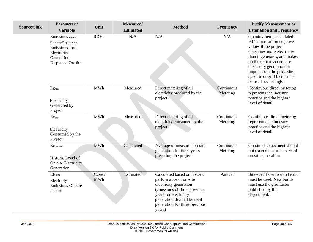
B14 – On-site Electricity Generation Displaced by Project
If (Eg proj – Ec proj) < 0, then: Emissions On-site Electricity Displacement = EFEG × (Eg proj – Ec proj) or EFEO × (Eg proj – Ec proj)
Otherwise: Emissions On-site Electricity Displacement = EFEO × lesser of [(Eg proj – Ec proj), Eg historic]
Jan 2018 Draft Quantification Protocol for Landfill Gas Capture and Combustion Page 38 of 55 Draft Version 3.0 for Public Comment
© 2018 Government of Alberta
Source/Sink Parameter /
Variable Unit
Measured/ Estimated
Method Frequency Justify Measurement or
Estimation and Frequency
Emissions On-site
Electricity Displacement
Emissions from Electricity Generation Displaced On-site
tCO2e N/A N/A N/A Quantity being calculated. B14 can result in negative values if the project consumes more electricity than it generates, and makes up the deficit via on-site electricity generation or import from the grid. Site specific or grid factor must be used accordingly.
Egproj Electricity Generated by Project
MWh Measured Direct metering of all electricity produced by the project
Continuous Metering
Continuous direct metering represents the industry practice and the highest level of detail.
Ecproj Electricity Consumed by the Project
MWh Measured Direct metering of all electricity consumed by the project
Continuous Metering
Continuous direct metering represents the industry practice and the highest level of detail.
Echistoric Historic Level of On-site Electricity Generation
MWh Calculated Average of measured on-site generation for three years preceding the project
Continuous Metering
On-site displacement should not exceed historic levels of on-site generation.
EF EO Electricty Emissions On-site Factor
tCO2e / MWh
Estimated Calculated based on historic performance of on-site electricity generation (emissions of three previous years for electricity generation divided by total generation for three previous years)
Annual Site-specific emission factor must be used. New builds must use the grid factor published by the department.

Jan 2018 Draft Quantification Protocol for Landfill Gas Capture and Combustion Page 39 of 55 Draft Version 3.0 for Public Comment
© 2018 Government of Alberta
Source/Sink Parameter /
Variable Unit
Measured/ Estimated
Method Frequency Justify Measurement or
Estimation and Frequency EF EG Electricty Emissions Grid Factor
tCO2e / MWh
Estimated Provided in Carbon Offset Emission Factors Handbook
N/A Reference value in Carbon Offset Emission Factors Handbook.
B20 – Supplemental Fossil Fuel Needed for Flaring
EmissionsFuel for Flare= VolFuel×[FCH4 × ρCH4 × DECH4 × 44/16 + FCH4 × ρCH4 × (1-DECH4) × GWPCH4 + EFN2O × GWPN2O/1000]
EmissionsFuel for Flare tonnes CO2e N/A N/A N/A Quantity of emissions from the burning of supplemental natural gas used for flaring in the baseline condition.
VolFuel
Volume of supplemental natural gas used
m3 Measured Direct metering or reconciliation of volumes transferred
Continuous metering or
monthly reconciliation
Both methods are standard practice. Frequency of metering is highest level possible. Frequency of reconciliation provides for reasonable diligence.
FCH4
Average Volume Fraction of Methane in the Supplemental Natural Gas
m3CH4 / m3
NG Estimated or measured based on
invoicing
At standard conditions Estimated or measured each
invoicing interval
According to the supplier’s specifications

Jan 2018 Draft Quantification Protocol for Landfill Gas Capture and Combustion Page 40 of 55 Draft Version 3.0 for Public Comment
© 2018 Government of Alberta
Source/Sink Parameter /
Variable Unit
Measured/ Estimated
Method Frequency Justify Measurement or
Estimation and Frequency ρCH4
Density of methane
tonnes CH4 / m3
CH4 Constant 0.0006785 at standard
temperature and pressure N/A If this value is used, all
volumes must be adjusted for standard temperature and pressure. Agreement must be achieved between volume and density of methane in the measurement. Values for CH4 density at other reference temperatures can be found in Table A2.
DE Destruction Efficiency of the flare
% Estimated Methane destruction efficiency of the combustion device. To be obtained from manufacturer or vendor’s specifications (or from Appendix A: Default Values for Methane Destruction Efficiency)
N/A The manufacturer or vendor’s specifications represent the industry practice and the highest level of detail.
44/16 Molar Mass Ratio of Carbon Dioxide to Methane
Unitless Constant N/A N/A N/A
GWPCH4
Global Warming Potential for CH4
Unitless Estimated Provided in Carbon Offset Emission Factors Handbook
N/A Reference value in Carbon Offset Emission Factors Handbook.

Jan 2018 Draft Quantification Protocol for Landfill Gas Capture and Combustion Page 41 of 55 Draft Version 3.0 for Public Comment
© 2018 Government of Alberta
Source/Sink Parameter /
Variable Unit
Measured/ Estimated
Method Frequency Justify Measurement or
Estimation and Frequency EFN2O
Emission factor for nitrous oxide as a result of natural gas combustion
kg N2O / m3 Constant Provided in Carbon Offset Emission Factors Handbook
N/A Reference value in Carbon Offset Emission Factors Handbook.
GWPN2O
Global Warming Potential for N2O
Unitless Estimated Provided in Carbon Offset Emission Factors Handbook
N/A Reference value in Carbon Offset Emission Factors Handbook.
B21 – Landfill Gas Combustion EmissionsLFG Combustion = [VolLFG × FCH4 × ρCH4 × (1 – DE) ×GWPCH4 + VolLFG × EFN2O × GWPN2O / 1000]
EmissionsLFG
Combustion tonnes CO2e N/A N/A N/A Quantity of emissions from
combusting landfill gas in the project.
VolLFG
Volume of LFG combusted in the combustion device (either a flare or energy recovery system)
m3LFG Direct metering
(measured or adjusted to represent
at standard temperature and
pressure)
Continuous metering Continuous Direct metering represents the industry practice and the highest level of detail.
FCH4
Average Fraction of Methane in the Landfill Gas
m3CH4 /
m3LFG
Measured Direct measurement Monthly sampling or more frequent
Landfill gas composition should remain relatively stable during steady-state operation.

Jan 2018 Draft Quantification Protocol for Landfill Gas Capture and Combustion Page 42 of 55 Draft Version 3.0 for Public Comment
© 2018 Government of Alberta
Source/Sink Parameter /
Variable Unit
Measured/ Estimated
Method Frequency Justify Measurement or
Estimation and Frequency ρCH4
Density of methane
tonnes CH4 / m3
CH4 Constant 0.0006785 at standard
temperature and pressure N/A If this value is used, all
volumes must be adjusted for standard temperature and pressure. Agreement must be achieved between volume and density of methane in the measurement. Values for CH4 density at other reference temperatures can be found in Table A2.
DE Destruction Efficiency of the flare
% Estimated Methane destruction efficiency of the combustion device. To be obtained from manufacturer or vendor’s specifications (or from Appendix A: Default Values for Methane Destruction Efficiency)
N/A The manufacturer or vendor’s specifications represent the industry practice and the highest level of detail.
GWPCH4
Global Warming Potential for CH4
Unitless Estimated Provided in Carbon Offset Emission Factors Handbook
N/A Reference value in Carbon Offset Emission Factors Handbook.
EFN2O
Emission factor for nitrous oxide as a result of landfill gas combustion
kg N2O / m3 Constant 0.0000108 at standard temperature and pressure
N/A Reference value in Greenhouse Gas Inventory Guidance: Direct Emissions from Stationary Combustion Sources published by the United States Environmental Protection Agency, 2016

Jan 2018 Draft Quantification Protocol for Landfill Gas Capture and Combustion Page 43 of 55 Draft Version 3.0 for Public Comment
© 2018 Government of Alberta
Source/Sink Parameter /
Variable Unit
Measured/ Estimated
Method Frequency Justify Measurement or
Estimation and Frequency GWPN2O
Global Warming Potential for N2O
Unitless Estimated Provided in Carbon Offset Emission Factors Handbook
N/A Reference value in Carbon Offset Emission Factors Handbook.
B22 - Fossil Fuel Use
EmissionsFossil Fuel Use = [∑ (VolFuel,i × EF Fueli,CO2) + ∑ (VolFuel,i × EF Fueli,CH4 × GWPCH4) + ∑ (VolFuel,i × EF Fueli,N2O × GWPN2O)] / 1000
EmissionsFossil Fuel
Use tonnes CO2e N/A N/A N/A Quantity being calculated in
aggregate form as fuel use on site for each source/sink in the project.
VolFuel,i Volume of Each Type of Fuel Offset by Landfill Gas Project
m3 Measured Direct metering or reconciliation of volumes transferred
Continuous metering or
monthly reconciliation
Both methods are standard practice. Frequency of metering is highest level possible. Frequency of reconciliation provides for reasonable diligence.
EF Fueli,CO2
CO2 Emission Factor for Each Fuel Combusted
kg CO2 / m3 Estimated Provided in Carbon Offset Emission Factors Handbook
N/A Reference value in Carbon Offset Emission Factors Handbook.
EF Fueli,CH4
CH4 Emission Factor for Each Fuel Combusted
kg CH4 / m3 Estimated Provided in Carbon Offset Emission Factors Handbook
N/A Reference value in Carbon Offset Emission Factors Handbook.

Jan 2018 Draft Quantification Protocol for Landfill Gas Capture and Combustion Page 44 of 55 Draft Version 3.0 for Public Comment
© 2018 Government of Alberta
Source/Sink Parameter /
Variable Unit
Measured/ Estimated
Method Frequency Justify Measurement or
Estimation and Frequency EF Fueli,N2O
N2O Emission Factor for Each Fuel Combusted
kg N2O / m3 Estimated Provided in Carbon Offset Emission Factors Handbook
N/A Reference value in Carbon Offset Emission Factors Handbook.
GWPCH4
Global Warming Potential for CH4
Unitless Estimated Provided Carbon Offset Emission Factors Handbook
N/A Reference value in Carbon Offset Emission Factors Handbook.
GWPN2O Global Warming Potential of N2O
Unitless Estimated Provided Carbon Offset Emission Factors Handbook
N/A Reference value in Carbon Offset Emission Factors Handbook.
Project Condition P4 - Fuel Extraction and Processing
EmissionFuel Extraction/Processing = [∑ (VolFuel,i × EFi,CO2) + ∑ (VolFuel,i × EFi,CH4 × GWPCH4) + ∑ (VolFuel,i × EFi,N2O × GWPN2O) ] / 1000
EmissionFuel
Extraction/Processing
Emissions from Fuel Extraction and Processing
tonnes CO2e N/A N/A N/A Quantity being calculated.

Jan 2018 Draft Quantification Protocol for Landfill Gas Capture and Combustion Page 45 of 55 Draft Version 3.0 for Public Comment
© 2018 Government of Alberta
Source/Sink Parameter /
Variable Unit
Measured/ Estimated
Method Frequency Justify Measurement or
Estimation and Frequency VolFuel,i Volume of Fuel Combusted (In P12 and P13)
L, m3, or Other
Measured Direct metering or reconciliation of volume in storage (including volumes received)
Continuous metering or
monthly reconciliation
Both methods are standard practice. Frequency of metering is highest level possible. Frequency of reconciliation provides for reasonable diligence.
EFi,CO2
CO2 Emission Factor for Extraction and Processing of Each Fuel
kg CO2 per L, m3, or
other
Estimated Provided in Carbon Offset Emission Factors Handbook
N/A Reference value in Carbon Offset Emission Factors Handbook.
EFi,CH4
CH4 Emission Factor for Extraction and Processing of Each Fuel
kg CH4 per L, m3, or
other
Estimated Provided in Carbon Offset Emission Factors Handbook
N/A Reference value in Carbon Offset Emission Factors Handbook.
EFi,N2O
N2O Emission Factor for Extraction and Processing of Each Fuel
kg N2O per L, m3, or
other
Estimated Provided in Carbon Offset Emission Factors Handbook
N/A Reference value in Carbon Offset Emission Factors Handbook.
GWPCH4
Global Warming Potential for CH4
Unitless Estimated Provided in Carbon Offset Emission Factors Handbook
N/A Reference value in Carbon Offset Emission Factors Handbook.

Jan 2018 Draft Quantification Protocol for Landfill Gas Capture and Combustion Page 46 of 55 Draft Version 3.0 for Public Comment
© 2018 Government of Alberta
Source/Sink Parameter /
Variable Unit
Measured/ Estimated
Method Frequency Justify Measurement or
Estimation and Frequency GWPN2O
Global Warming Potential for N2O
Unitless Estimated Provided in Carbon Offset Emission Factors Handbook
N/A Reference value in Carbon Offset Emission Factors Handbook.
P12 - Fossil Fuel Use
EmissionsFossil Fuel Use = [∑ (VolFuel,i × EF Fueli,CO2) + ∑ (VolFuel,i × EF Fueli,CH4 × GWPCH4) + ∑ (VolFuel,i × EF Fueli,N2O × GWPN2O)] / 1000
EmissionsFossil Fuel
Use tonnes CO2e N/A N/A N/A Quantity being calculated in
aggregate form as fuel use on site for each source/sink in the project.
VolFuel,i Volume of Each Type of Fuel used to run the landfill gas combustion and recovery system
m3 Measured Direct metering or reconciliation of volumes transferred
Continuous metering or
monthly reconciliation
Both methods are standard practice. Frequency of metering is highest level possible. Frequency of reconciliation provides for reasonable diligence.
EF Fueli,CO2
CO2 Emission Factor for Each Fuel Combusted
kgCO2 / m3 Estimated Provided in Carbon Offset Emission Factors Handbook
N/A Reference value in Carbon Offset Emission Factors Handbook.
EF Fueli,CH4
CH4 Emission Factor for Each Fuel Combusted
kgCH4 / m3 Estimated Provided in Carbon Offset Emission Factors Handbook
N/A Reference value in Carbon Offset Emission Factors Handbook.
EF Fueli,N2O
N2O Emission Factor for Each Fuel Combusted
kgN2O / m3 Estimated Provided in Carbon Offset Emission Factors Handbook
N/A Reference value in Carbon Offset Emission Factors Handbook.

Jan 2018 Draft Quantification Protocol for Landfill Gas Capture and Combustion Page 47 of 55 Draft Version 3.0 for Public Comment
© 2018 Government of Alberta
Source/Sink Parameter /
Variable Unit
Measured/ Estimated
Method Frequency Justify Measurement or
Estimation and Frequency GWPCH4
Global Warming Potential for CH4
Unitless Estimated Provided Carbon Offset Emission Factors Handbook
N/A Reference value in Carbon Offset Emission Factors Handbook.
GWPN2O
Global Warming Potential for N2O
Unitless Estimated Provided Carbon Offset Emission Factors Handbook
N/A Reference value in Carbon Offset Emission Factors Handbook.
P13- Supplemental Fossil Fuel Needed for Flaring
EmissionsFuel for Flare= VolFuel×[FCH4 × ρCH4 × DECH4 × 44/16 + FCH4 × ρCH4 × (1-DECH4) × GWPCH4 + EFN2O × GWPN2O / 1000]
EmissionsFuel for Flare
tonnes CO2e N/A N/A N/A Quantity of emissions from the burning of supplemental natural gas used for flaring in the baseline condition.
VolFuel
Volume of supplemental natural gas used
m3 Measured Direct metering or reconciliation of volumes transferred
Continuous metering or
monthly reconciliation
Both methods are standard practice. Frequency of metering is highest level possible. Frequency of reconciliation provides for reasonable diligence.
FCH4
Average Volume Fraction of Methane in the Supplemental Natural Gas
m3CH4 / m3
NG Estimated or measured based on
invoicing
At standard conditions Estimated or measured each
invoicing interval
According to the supplier’s specifications

Jan 2018 Draft Quantification Protocol for Landfill Gas Capture and Combustion Page 48 of 55 Draft Version 3.0 for Public Comment
© 2018 Government of Alberta
Source/Sink Parameter /
Variable Unit
Measured/ Estimated
Method Frequency Justify Measurement or
Estimation and Frequency ρCH4
Density of methane
tonnes CH4 / m3
CH4
Constant 0.0006785 at standard temperature and pressure
N/A If this value is used, all volumes must be adjusted for standard temperature and pressure. Agreement must be achieved between volume and density of methane in the measurement. Values for CH4 density at other reference temperatures can be found in Table A2.
DE Destruction Efficiency of the flare
% Estimated Methane destruction efficiency of the combustion device. To be obtained from manufacturer or vendor’s specifications (or from Appendix A: Default Values for Methane Destruction Efficiency)
N/A The manufacturer or vendor’s specifications represent the industry practice and the highest level of detail.
44/16 Molar Mass Ratio of Carbon Dioxide to Methane
Unitless Constant N/A N/A N/A
GWPCH4
Global Warming Potential for CH4
Unitless Estimated Provided in Carbon Offset Emission Factors Handbook
N/A Reference value in Carbon Offset Emission Factors Handbook.
EFN2O
Emission factor for nitrous oxide as a result of natural gas combustion
kg N2O / m3 Constant Provided in Carbon Offset Emission Factors Handbook
N/A Reference value in Carbon Offset Emission Factors Handbook.

Jan 2018 Draft Quantification Protocol for Landfill Gas Capture and Combustion Page 49 of 55 Draft Version 3.0 for Public Comment
© 2018 Government of Alberta
Source/Sink Parameter /
Variable Unit
Measured/ Estimated
Method Frequency Justify Measurement or
Estimation and Frequency GWPN2O
Global Warming Potential for N2O
Unitless Estimated Provided in Carbon Offset Emission Factors Handbook
N/A Reference value in Carbon Offset Emission Factors Handbook.
P16 –Landfill Gas Combustion
Emissions LFG Combustion = [VolLFG × FCH4 × ρCH4 × (1 – DE) ×GWPCH4 + VolLFG × EFN2O × GWPN2O / 1000]
Emissions LFG
Combustion tonnes CO2e N/A N/A N/A Quantity of emissions from
combusting landfill gas in the project.
VolLFG
Volume of LFG combusted in the combustion device (either a flare or energy recovery system)
m3LFG
Direct metering (measured or adjusted to represent at standard temperature and pressure)
Continuous metering Continuous Direct metering represents the industry practice and the highest level of detail.
FCH4
Average Fraction of Methane in the Landfill Gas
m3CH4 /
m3LFG
Measured Direct measurement Monthly sampling or more frequent
Landfill gas composition should remain relatively stable during steady-state operation.
ρCH4
Density of methane
tonnes CH4 / m3
CH4 Constant 0.0006785 at standard
temperature and pressure N/A If this value is used, all
volumes must be adjusted for standard temperature and pressure. Agreement must be achieved between volume and density of methane in the measurement. Values for CH4 density at other reference temperatures can be found in Table A2.

Jan 2018 Draft Quantification Protocol for Landfill Gas Capture and Combustion Page 50 of 55 Draft Version 3.0 for Public Comment
© 2018 Government of Alberta
Source/Sink Parameter /
Variable Unit
Measured/ Estimated
Method Frequency Justify Measurement or
Estimation and Frequency DE Destruction Efficiency of the flare
% Estimated Methane destruction efficiency of the combustion device. To be obtained from manufacturer or vendor’s specifications (or from Appendix A: Default Values for Methane Destruction Efficiency)
N/A The manufacturer or vendor’s specifications represent the industry practice and the highest level of detail.
GWPCH4
Global Warming Potential for CH4
Unitless Estimated Provided in Carbon Offset Emission Factors Handbook
N/A Reference value in Carbon Offset Emission Factors Handbook.
EFN2O
Emission factor for nitrous oxide as a result of landfill gas combustion
kg N2O / m3 Constant 0.0000108 at standard temperature and pressure
N/A Reference value in Greenhouse Gas Inventory Guidance: Direct Emissions from Stationary Combustion Sources published by the United States Environmental Protection Agency, 2016
GWPN2O
Global Warming Potential for N2O
Unitless Estimated Provided in Carbon Offset Emission Factors Handbook
N/A Reference value in Carbon Offset Emission Factors Handbook.

Jan 2018 Draft Quantification Protocol for Landfill Gas Capture and Combustion Page 51 of 55 Draft Version 3.0 for Public Comment
© 2018 Government of Alberta
5.0 Documents and Records
Documentation (documents and records) are a key element to project development. The types of documents and records required to demonstrate that an offset project meets regulatory and protocol requirements can vary by project. It is the project developer’s responsibility to ensure the project plan clearly outlines documents and records for the offset project.
The verification process relies heavily on the quality and availability of documentation to support the GHG assertion. Projects are audited to a reasonable level of assurance. A list of required objective evidence of project implementation is outlined in Table 7. Attestation is not considered objective evidence and is not accepted as proof that an activity took place.
Documents and records are required to be:
• Legible, identifiable, traceable; • Centrally located; • Dated; • Easily located (easily searched); • Orderly; • Retained as per section 29(4) of the Carbon Competitiveness Incentive Regulation; and, • Prevented from loss.
In the case of aggregated projects, subproject owners and the aggregator must both retain records as required above.
Project developers, including aggregators, are required to retain copies of all required records and any additional records needed to support the GHG reduction. The project developer shall establish and apply quality management procedures to manage data and information. Written procedures must be established for each measurement task outlining responsibility, timing and record location requirements. The greater the rigour of the management system for the data, the more easily verification/audit can be conducted for the project.
5.1 Documents
Documents are the instructions or plan on how a certain activity is carried out.
Documents may be required to demonstrate that an offset project meets program criteria, eligibility, baseline eligibility and project offset quantification. Examples of documents include offset project plan, procedures, specifications, drawings, regulations, standards, guidelines, etc. These documents must include a list of records available to the verifier that demonstrate the offset criteria have been met. The offset project documents should also indicate how the records will be managed (i.e., retention, storage and access).
Documents may be stand-alone or interdependent. Documents may be subject to change or periodic update. The project developer must be able to demonstrate that the most current quantification version of a document is being used. Older versions applicable to specific GHG assertions must be retained as part of the project documentation as per section 29(4) of the Carbon Competitiveness Incentive Regulation.
In addition to the criteria outlined in this protocol, the offset project developer is required to provide documents to show that general offset criteria in the Standard for Greenhouse Gas Emission Offset Project Developers have been met. These criteria are summarized in Table 6.

Jan 2018 Draft Quantification Protocol for Landfill Gas Capture and Combustion Page 52 of 55 Draft Version 3.0 for Public Comment
© 2018 Government of Alberta
Table 6: Examples of Documents Required to Meet Offset Criteria Offset Criterion Example of Document Counted once Written explanation of where the risks of double counting may be and
mitigation strategies to ensure that no double counting occurs. Mitigation strategies should include a methodology for assuring no double counting.
Beyond business as usual (BAU) and sector common practice
Requirements outlined in the Carbon Competitiveness Incentive Regulation and future additionality directives are met.
No leakage Written explanation of how the project ensures there is no carbon leakage. Permanence Written explanation of how permanence is addressed. Project eligibility Written explanation of how the project is eligible to generate emission offsets.
Criteria include demonstrating ownership, project location within Alberta, and adherence to an approved protocol.
Baseline condition Methodology used to measure baseline condition stated in the protocol (this is the baseline practice over the three year period immediately prior to the offset project start date). The baseline condition must address the level of service, frequency and duration of measurement, units, emissions factors, and default values for quantifying baseline emissions.
Project quantification Methodology used to measure the project condition over the entire project period. Project quantification includes the frequency and duration of the measurement, units, emissions factors, frequency of calibration, default values for quantifying emissions, and other relevant criteria stated in the protocol.
5.2 Records
Records are required to prove completion of the project as planned. Records include, but are not limited to, invoices, contracts, metered results, maintenance logs, calculations, databases, photographs, calibration records, etc.
Records must be retained according to the requirements outlined in Section 5.0 and as indicated in the offset project plan. In the case of an aggregated project, the individuals and the aggregator must both retain sufficient records to demonstrate that the offset criteria have been met. Table 7 outlines examples of records that may be required to support this protocol. Records must be available and be disclosed to a verifier and/or government auditor upon request.
Table 7: Record Requirements and Examples of Records Record Requirement Examples of Records
Project in Alberta • Evidence that the project has occurred in Alberta.
Activity start date on or after January 1, 2002
• Evidence that the reduction activity started on or after January 1, 2002 such as a work order, invoice, or dated procedure.
Ownership • Evidence that the emission offsets are clearly owned or allowed to be collected by the project developer, which may include agreements, contracts, etc.
Measurement equipment
• Description of meters used, meter model number, serial number, manufacturer’s calibration procedures and calibration records or standards of calibration.
• For commercial purchases, proof of commercial grade metering from the supplier is required.
• For computer control system data, a description of the data.

Jan 2018 Draft Quantification Protocol for Landfill Gas Capture and Combustion Page 53 of 55 Draft Version 3.0 for Public Comment
© 2018 Government of Alberta
Baseline calculations
• Raw data in database and/or spreadsheet format, including all necessary information for the project’s baseline condition such as records of on-site heat generation, on-site electricity generation, and extent of landfill gas flaring. The data must include three years that immediately precede the project.
• If sampling was used, summary statistics and methods used to calculate statistics.
• A record of all adjustments made to raw baseline data with justifications.
Project calculations • Raw data and calculations in database and/or spreadsheet format. • If sampling was used, summary statistics and methods used to calculate
statistics. • A record of all adjustments made to raw project data with justifications.
All calculations of greenhouse gas emissions/reductions and emission factors used.
• Spreadsheet format or hardcopy with formula and emission factors included. • Dates and sources for all emission factors used. • Calculations for site-specific emission factors used.
Level of service • Landfill gas production records.
Energy consumed/produced
• Amount of energy consumed on- and off-site including from handling, metered use, invoices, etc.
Pilot Status • Evidence that the project is a pilot project, if applicable
Carbon levy exemption certificate
• Carbon levy exemption certificate, if applicable
Note: Attestations are not considered sufficient proof that an activity took place and do not meet verification requirements.
5.3 Quality Assurance/Quality Control Considerations
Quality Assurance/Quality Control (QA/QC) procedures are applied to add confidence that all measurements and calculations have been made correctly. These include, but are not limited to:
• Ensuring that the changes to operational procedures continue to function as planned and achieve GHG reductions;
• Ensuring that the measurement and calculation system and GHG reduction reporting remains in place and accurate;
• Checking the validity of all data before it is processed, including emission factors, static factors and acquired data;
• Performing recalculations of quantification procedures to reduce the possibility of mathematical errors;
• Storing the data in its raw form so it can be retrieved for verification;
• Protecting records of data and documentation;
• Recording and explaining any adjustment made to raw data in the associated report and files;

Jan 2018 Draft Quantification Protocol for Landfill Gas Capture and Combustion Page 54 of 55 Draft Version 3.0 for Public Comment
© 2018 Government of Alberta
• A contingency plan for potential data loss;
• Instrument calibration performed regularly to ensure accuracy; and,
• Sampling protocols are followed to ensure accuracy.
5.4 Liability
Carbon offset projects must be implemented according to the approved protocol and in accordance with government regulations. The department reserves the right to re-verify emission offsets and associated projects submitted to the department for compliance under the Carbon Competitiveness Incentive Regulation and may require corrections based on re-verification findings.

Jan 2018 Draft Quantification Protocol for Landfill Gas Capture and Combustion Page 55 of 55 Draft Version 3.0 for Public Comment
© 2018 Government of Alberta
APPENDIX A: Quantification Parameters Methane Destruction Efficiency
The methane destruction efficiency (DECH4) is defined as the amount of methane destroyed through flares, engines or turbines. The following default values are taken from the Technical Guidance for the Quantification of Specified Gas Emissions from Landfills which refers to the USEPA for non–halogenated species2. They are distinguished between boiler/steam and gas turbines, flares and internal combustion (IC) engines.
Table A1: Default Values for Methane Destruction Efficiency (USEPA) Type of LFG Control Device Methane Destruction Efficiency
Range (%) Average (%) Boiler / Steam Turbines 67-99+ 99.8 Gas Turbines 97-99+ 98.2 Unassisted Flares 38-99+ 98.0 Air or Steam Assisted Flares^ 38-99+ 99.5 IC Engines 25-99+ 86.1* (98+) Passive Venting 0
*A recent review of literature and experiences from members of the Landfill Gas Working Group have shown average destruction efficiencies for IC engines of 98% or greater. ^Must be properly operated and highly turbulent
Methane Density The appropriate methane density can be selected from Table A2 based on the desired reference temperature. Table A2: Density of CH4 at 1 atm/101.325kPa
Temperature (°C) Temperature (K) Density (kg/m3)3 0 273.15 0.718 5 278.15 0.705
10 283.15 0.692 15 288.15 0.680 20 293.15 0.668 25 298.15 0.657
2 United States Environmental Protection Agency. (1998). 2.4 Municipal Solid Waste Landfills. In AP-42. Retrieved from http://www.epa.gov/ttnchie1/ap42/ch02/final/c02s04.pdf 3 Setzmann, U., & Wagner, W. (1991). A New Equation of State and Tables of Thermodynamic Properties for Methane Covering the Range from the Melting Line to 625 K at Pressures up to 1000 MPa.J. Phys. Chem. Ref. Data, 20(6):1061-1151.