draft specification for accident site communication …
TRANSCRIPT
Page 1 of 23 Effective from : 09.11.2011 RDSO/ SPN/TC/55/2011 Rev. : 2
SPECIFICATION FOR ACCIDENT SITE COMMUNICATION SYSTEM SYSTEMSYSTEMSYSSYSTEMSYSYSSYSYSTEM
DRAFT SPECIFICATION
FOR
ACCIDENT SITE COMMUNICATION SYSTEM
SPECIFICATION No. RDSO/ SPN/ TC/55/2011
Revision 2
TELECOM DIRECTORATE
RESEARCH DESIGNS AND STANDARDS ORGANISATION
MINISTRYOF RAILWAYS MANAK NAGAR, LUCKNOW - 226001
Page 2 of 23 Effective from : 09.11.2011 RDSO/ SPN/TC/55/2011 Rev. : 2
SPECIFICATION FOR ACCIDENT SITE COMMUNICATION SYSTEM SYSTEMSYSTEMSYSSYSTEMSYSYSSYSYSTEM
DRAFT SPECIFICATION FOR
ACCIDENT SITE COMMUNICATION SYSTEM
SPECIFICATION NO. : RDSO/ SPN/TC/55/2011
DOCUMENT DATA SHEET
SPECIFICATION
RDSO/SPN/TC/55/2011 REV 2
TITLE OF DOCUMENT
DRAFT RDSO SPECIFICATION FOR ACCIDENT SITE COMMUNICATION SYSTEM.
AUTHOR
DIRECTOR/ TELECOM-III/ RDSO
APPROVED BY
EXECUTIVE DIRECTOR/ TELECOM/ RDSO
ABSTRACT
THIS DOCUMENT SPECIFIES TECHNICAL SPECIFICATION OF ACCIDENT SITE COMMUNICATION SYSTEM.
Page 3 of 23 Effective from : 09.11.2011 RDSO/ SPN/TC/55/2011 Rev. : 2
SPECIFICATION FOR ACCIDENT SITE COMMUNICATION SYSTEM SYSTEMSYSTEMSYSSYSTEMSYSYSSYSYSTEM
DOCUMENT CONTROL SHEET
NAME ORGANIZATION FUNCTION LEVEL
DIRECTOR/TELECOM-III RDSO MEMBER PREPARE
EXECUTIVE DIRECTOR / TELECOM RDSO - APPROVE
REVISIONS
VERSION REVISION EFFECTIVE MONTH/YEAR
RDSO/SPN/TC/55-2005 FIRST ISSUE NOV., 2005
RDSO/SPN/TC/55-2006 FIRST REVISION AUGUST, 2006
RDSO/SPN/TC/55-2009, REV. 0 SECOND REVISION FEBRUARY, 2009
RDSO/SPN/TC/55-2009, REV. 1 THIRD REVISION FEBRUARY, 2009
RDSO/SPN/TC/55-2011, REV.2 FOURTH REVISION NOV., 2011
Page 4 of 23 Effective from : 09.11.2011 RDSO/ SPN/TC/55/2011 Rev. : 2
SPECIFICATION FOR ACCIDENT SITE COMMUNICATION SYSTEM SYSTEMSYSTEMSYSSYSTEMSYSYSSYSYSTEM
I. SUMMARY
This document covers the requirements of communication system to be established
at the site of accident/Unusual to enable transmission of Voice, data and video from
site to control office/ other locations.
II. SOURCE
(i) Draft specification RDSO/SPN/TC/55/2005 was prepared by RDSO,
Lucknow based on the experience gained by various Railways with the
WLL exchange based accident site communication system.
(ii) The specification has since been revised and now being revised based on
the experience gained from the use of accident site equipment supplied for
other than A route divisions.
(iii) Whenever reference to any specification appears in this document, it shall
be taken as a reference to the latest version of that specification unless the
year of issue of the specification is specifically stated.
1.0 Introduction: Accident site communication system will cater for onsite wireless voice
communication and also to provide voice, data and video connectivity of the accident site
to Divisional HQ, Zonal HQ and Railway Board.
For video transmission a mesh Wi-Fi network will be created at the site and with video camera the video shall be wirelessly transmitted to the Multi service gateway. The voice, data and video connectivity with remote locations will be provided through
VSAT network. Indian Railways have established its own VSAT network including hub.
Presently Indian Railways have hired bandwidth from transponder of INSAT-4CR (Ku
Band) satellite. Hub for this VSAT network has been set at New Delhi by M/s Hughes.
The network is in star topology.
The VSAT terminal to be used for Accident Site Communication shall be able to deliver
bidirectional composite data traffic (Voice, Video and Data) at a speed of 2Mbps.
However the actual working bandwidth may be limited in compliance of regulatory
requirements.
The VSAT terminal will deliver the composite data traffic from site to the VSAT hub at
New Delhi. From here the composite data traffic wil l be t ranspor t ed to Divisional
HQ, Zonal HQ and Railway Board on existing MPLS network.
A video server shall be provided at New Delhi VSAT hub to enable web based access to
live and stored videos.
Page 5 of 23 Effective from : 09.11.2011 RDSO/ SPN/TC/55/2011 Rev. : 2
SPECIFICATION FOR ACCIDENT SITE COMMUNICATION SYSTEM SYSTEMSYSTEMSYSSYSTEMSYSYSSYSYSTEM
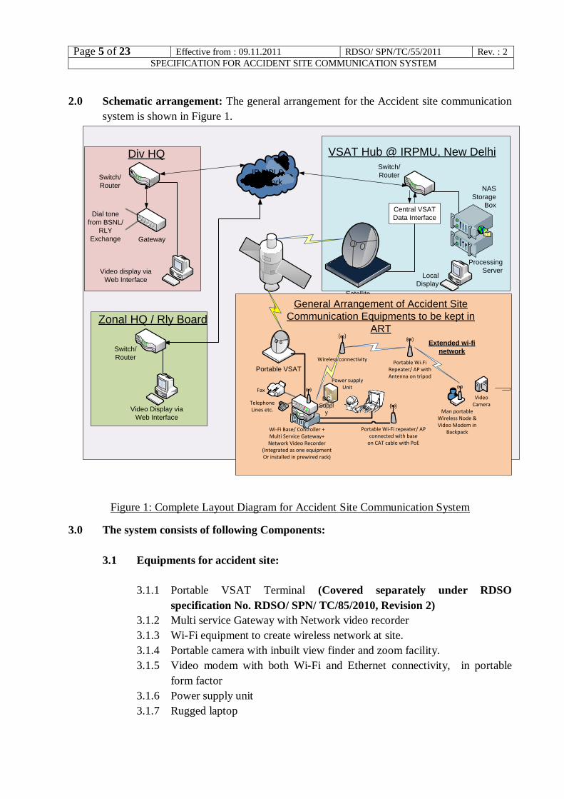
2.0 Schematic arrangement: The general arrangement for the Accident site communication
system is shown in Figure 1.
Portable VSAT
Video
CameraMan portable
Wireless Node &
Video Modem in
Backpack
Portable Wi-Fi
Equipment with
Antenna on tripod
Telephone
Lines etc.
Field Interface Unit in ART
Central VSAT
Data Interface
Local
Display
NAS
Storage
Box
Processing
Server
VSAT Hub @ IRPMU, New Delhi
IP MPLS
Network
Div HQ
Dial tone
from BSNL/
RLY
Exchange
Video display via
Web Interface
Zonal HQ / Rly Board
Video Display via
Web Interface
Satellite
Switch/
Router
Gateway
Fax
Switch/
Router
Portable Wi-Fi Equipment
connected on ethernet with PoE
Portable Wi-Fi
equipment with
Antenna on tripod
Wi-fi equipment
+Multi Service
Gateway+ Network
Video recorder
Integrated unit
Switch/
Router
Portable VSAT
VideoCamera
Man portableWireless Node &Video Modem in
Backpack
Portable Wi-FiRepeater/ AP withAntenna on tripod
Telephone Lines etc.
General Arrangement of Accident Site
Communication Equipments to be kept in
ART
Fax
Portable Wi-Fi repeater/ AP connected with base
on CAT cable with PoE
Wireless connectivity
Wi-Fi Base/ Controller +Multi Service Gateway+Network Video Recorder
(Integrated as one equipmentOr installed in prewired rack)
Extended wi-fi
network
Power supply Unit
DC
Suppl
y
Figure 1: Complete Layout Diagram for Accident Site Communication System
3.0 The system consists of following Components:
3.1 Equipments for accident site:
3.1.1 Portable VSAT Terminal (Covered separately under RDSO
specification No. RDSO/ SPN/ TC/85/2010, Revision 2)
3.1.2 Multi service Gateway with Network video recorder
3.1.3 Wi-Fi equipment to create wireless network at site.
3.1.4 Portable camera with inbuilt view finder and zoom facility.
3.1.5 Video modem with both Wi-Fi and Ethernet connectivity, in portable
form factor
3.1.6 Power supply unit
3.1.7 Rugged laptop
Page 6 of 23 Effective from : 09.11.2011 RDSO/ SPN/TC/55/2011 Rev. : 2
SPECIFICATION FOR ACCIDENT SITE COMMUNICATION SYSTEM SYSTEMSYSTEMSYSSYSTEMSYSYSSYSYSTEM
3.1.8 Necessary cables
3.1.9 Fax machine
3.1.10 Analog telephones
3.2 Equipment at VSAT Hub
3.2.1 Video server with storage
3.3 Equipments in Divisional HQ
3.3.1 Multi service Gateway
4.0 General requirements:
4.1 Multi service gateway shall enable
4.1.1 Voice connectivity by providing FXS at site/ FXO at divisional HQ.
4.1.2 IP connectivity for wireless units, laptop etc.
4.2 It shall be possible to extend dial tones of Railway Telephone exchange and
Public (BSNL/ MTNL) telephone exchange from divisional head quarter to the
site using FXS/ FXO interfaces on multi service gateways. It shall be possible to
make and receive calls to and from subscriber of these exchanges. It shall also be
possible to send and receive fax on the fax machine connected to FXS port at site.
4.3 Multi service gateways shall support hot line interfaces also. These interfaces
shall provide hot line connection between the analog telephones provided at
Divisional HQ and accident site. On this circuit, ring shall be extended just by
lifting the handset. As a confirmation of ring, ring back tone shall also be
provided.
4.4 Multiservice gateway shall have multiple Ethernet ports for connecting various
devices on Ethernet ports on LAN side. These devices may be laptop, Wi-Fi base
unit, Local network Video recorder (NVR), video modem etc.
4.5 Multiservice gateway’s Ethernet WAN port shall provide connectivity to VSAT
modem.
4.6 Multiservice gateway can be a single equipment or combination of router/ L3
Switch and IP PBX that can support FXS/FXO, subject to meeting the
requirements of this documents.
4.7 Wi-Fi equipment shall setup wireless quickly and easily. It shall be possible to
extend the coverage area by adding repeaters/ nodes/ access points.
4.8 The portable video camera with video modem and Wi-Fi network shall be
compatible with each other. The live video and audio captured by the video
camera shall be converted to suitable format and compressed by video modem
and network video recorder unit either on Wi-Fi or on Ethernet. The video
camera and video modem can be integrated also, provided the requirement of
portability is met.
Page 7 of 23 Effective from : 09.11.2011 RDSO/ SPN/TC/55/2011 Rev. : 2
SPECIFICATION FOR ACCIDENT SITE COMMUNICATION SYSTEM SYSTEMSYSTEMSYSSYSTEMSYSYSSYSYSTEM
4.9 The live video/ audio feed from video modem and/ or IP camera can directly be
given to the network video recorder through ports on Multi service gateway on
CAT 6 cable in case the area to be covered is small and Wi-Fi network is not
required to be set up.
4.10 The network video recorder shall stream the live video at a reduced resolution as
per available bandwidth on satellite link to the video server provided at IRPMU
Hub. The network video recorder shall also record video being streamed to the
video server. This locally recorded video shall be in high resolution.
4.11 Laptop is provided at site for configuration purpose and to monitor the system
performance.
4.12 The video transmitted from site shall be stored in the Video server with storage
device provided at IRPMU hub. The video server shall allow viewing of live and
recorded video and audio through internet browsers like internet explorer.
4.13 The video server at Hub shall allow recording and streaming of live video streams
coming from multiple sites.
4.14 It shall be possible to access the internet using laptop connected on any of the
Ethernet ports of the multiservice gateway or through wi-fi.
4.15 The system shall be plug and play and shall not require any configuration every
time it is used. The configuration shall be done only during first deployment and
backup for all the necessary configuration shall be taken for the purpose of
restoration in case of need.
4.16 For equipments working on AC supply, the nominal frequency shall be 50 Hz.
However they shall be capable of working on generator supply having frequency
deviated from the nominal frequency.
4.17 All necessary software and hardware to achieve above functionality shall be part
of the accident site communication system equipments even if it is not mentioned
explicitly in this document.
5.0 Specification of Equipments at accident site.
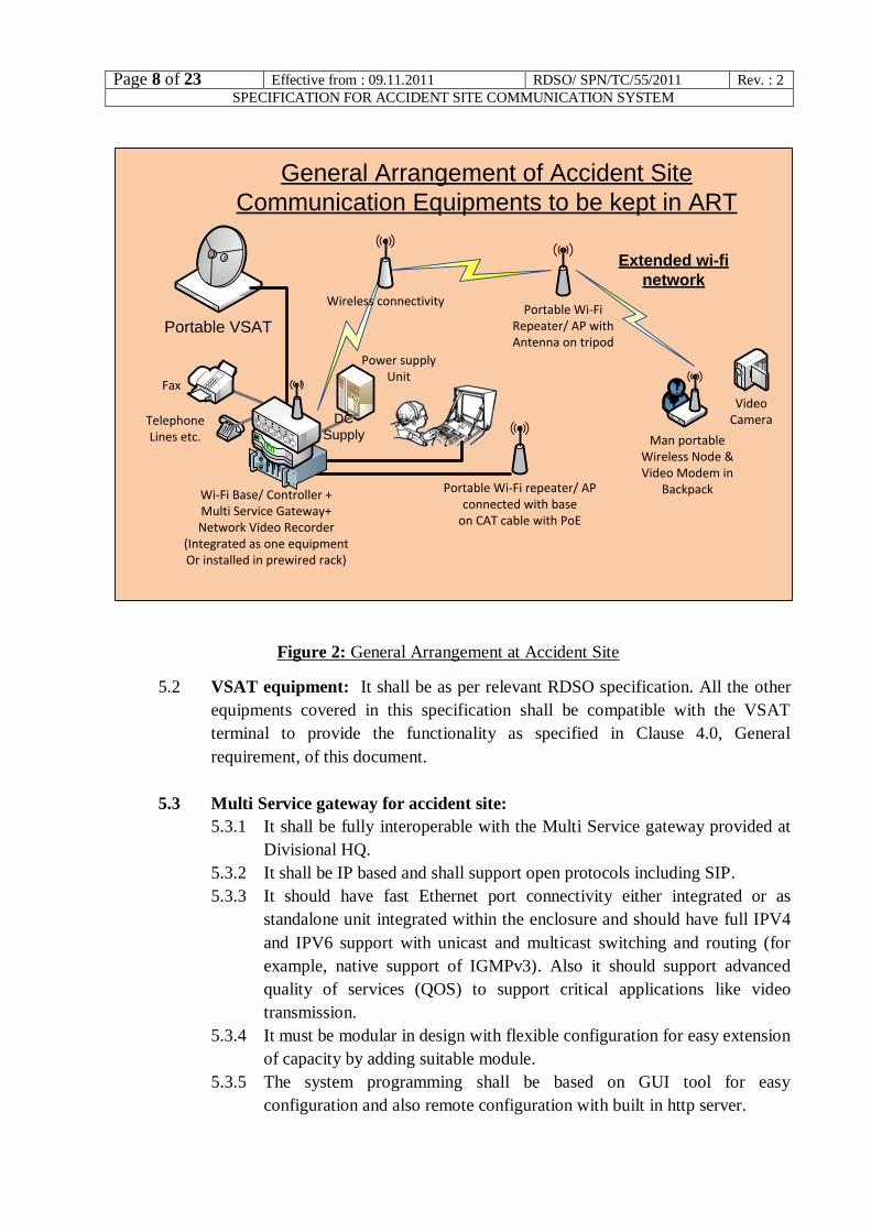
5.1 The general arrangement for accident site equipments is shown in Figure 2.
Page 8 of 23 Effective from : 09.11.2011 RDSO/ SPN/TC/55/2011 Rev. : 2
SPECIFICATION FOR ACCIDENT SITE COMMUNICATION SYSTEM SYSTEMSYSTEMSYSSYSTEMSYSYSSYSYSTEM
Portable VSAT
VideoCamera
Man portableWireless Node &Video Modem in
Backpack
Portable Wi-FiRepeater/ AP withAntenna on tripod
Telephone Lines etc.
General Arrangement of Accident Site
Communication Equipments to be kept in ART
Fax
Portable Wi-Fi repeater/ AP connected with base
on CAT cable with PoE
Wireless connectivity
Wi-Fi Base/ Controller +Multi Service Gateway+Network Video Recorder
(Integrated as one equipmentOr installed in prewired rack)
Extended wi-fi
network
Power supply Unit
DC
Supply
Figure 2: General Arrangement at Accident Site
5.2 VSAT equipment: It shall be as per relevant RDSO specification. All the other
equipments covered in this specification shall be compatible with the VSAT
terminal to provide the functionality as specified in Clause 4.0, General
requirement, of this document.
5.3 Multi Service gateway for accident site:
5.3.1 It shall be fully interoperable with the Multi Service gateway provided at
Divisional HQ.
5.3.2 It shall be IP based and shall support open protocols including SIP.
5.3.3 It should have fast Ethernet port connectivity either integrated or as
standalone unit integrated within the enclosure and should have full IPV4
and IPV6 support with unicast and multicast switching and routing (for
example, native support of IGMPv3). Also it should support advanced
quality of services (QOS) to support critical applications like video
transmission.
5.3.4 It must be modular in design with flexible configuration for easy extension
of capacity by adding suitable module.
5.3.5 The system programming shall be based on GUI tool for easy
configuration and also remote configuration with built in http server.
Page 9 of 23 Effective from : 09.11.2011 RDSO/ SPN/TC/55/2011 Rev. : 2
SPECIFICATION FOR ACCIDENT SITE COMMUNICATION SYSTEM SYSTEMSYSTEMSYSSYSTEMSYSYSSYSYSTEM
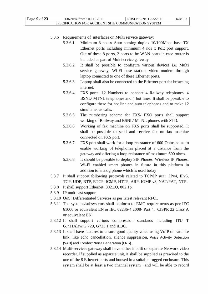
5.3.6 Requirements of interfaces on Multi service gateway:
5.3.6.1 Minimum 8 nos x Auto sensing duplex 10/100Mbps base TX
Ethernet ports including minimum 4 nos x PoE port support.
Out of these 8 ports, 2 ports to be WAN ports in case router is
included as part of Multiservice gateway.
5.3.6.2 It shall be possible to configure various devices i.e. Multi
service gateway, Wi-Fi base station, video modem through
laptop connected to one of these Ethernet ports.
5.3.6.3 Laptop shall also be connected to the Ethernet port for browsing
internet.
5.3.6.4 FXS ports: 12 Numbers to connect 4 Railway telephones, 4
BSNL/ MTNL telephones and 4 hot lines. It shall be possible to
configure these for hot line and auto telephones and to make 12
simultaneous calls.
5.3.6.5 The numbering scheme for FXS/ FXO ports shall support
working of Railway and BSNL/ MTNL phones with STD.
5.3.6.6 Working of fax machine on FXS ports shall be supported. It
shall be possible to send and receive fax on fax machine
connected on FXS port.
5.3.6.7 FXS port shall work for a loop resistance of 600 Ohms so as to
enable working of telephones placed at a distance from the
gateway and offering a loop resistance of maximum 600 ohms.
5.3.6.8 It should be possible to deploy SIP Phones, Wireless IP Phones,
Wi-Fi enabled smart phones in future in this platform in
addition to analog phone which is used today
5.3.7 It shall support following protocols related to TCP/IP suit: IPv4, IPv6,
TCP, UDP, RTP, RTCP, ICMP, HTTP, ARP, IGMP v3, NAT/PAT, NTP.
5.3.8 It shall support Ethernet, 802.1Q, 802.1p.
5.3.9 IP multicast support
5.3.10 QoS: Differentiated Services as per latest relevant RFC..
5.3.11 The systems/subsystems shall conform to EMC requirements as per IEC
61000 or equivalent EN or IEC 62236-4:2008- Part 4, CISPR 22 Class A
or equivalent EN
5.3.12 It shall support various compression standards including ITU T
G.711Alaw,G.729, G723.1 and iLBC.
5.3.13 It shall have features to ensure good quality voice using VoIP on satellite
link, like echo cancellation, silence suppression, Voice Activity Detection
(VAD) and Comfort Noise Generation (CNG)..
5.3.14 Multi-services gateway shall have either inbuilt or separate Network video
recorder. If supplied as separate unit, it shall be supplied as prewired to the
one of the 8 Ethernet ports and housed in a suitable rugged enclosure. This
system shall be at least a two channel system and will be able to record
Page 10 of 23 Effective from : 09.11.2011 RDSO/ SPN/TC/55/2011 Rev. : 2
SPECIFICATION FOR ACCIDENT SITE COMMUNICATION SYSTEM SYSTEMSYSTEMSYSSYSTEMSYSYSSYSYSTEM
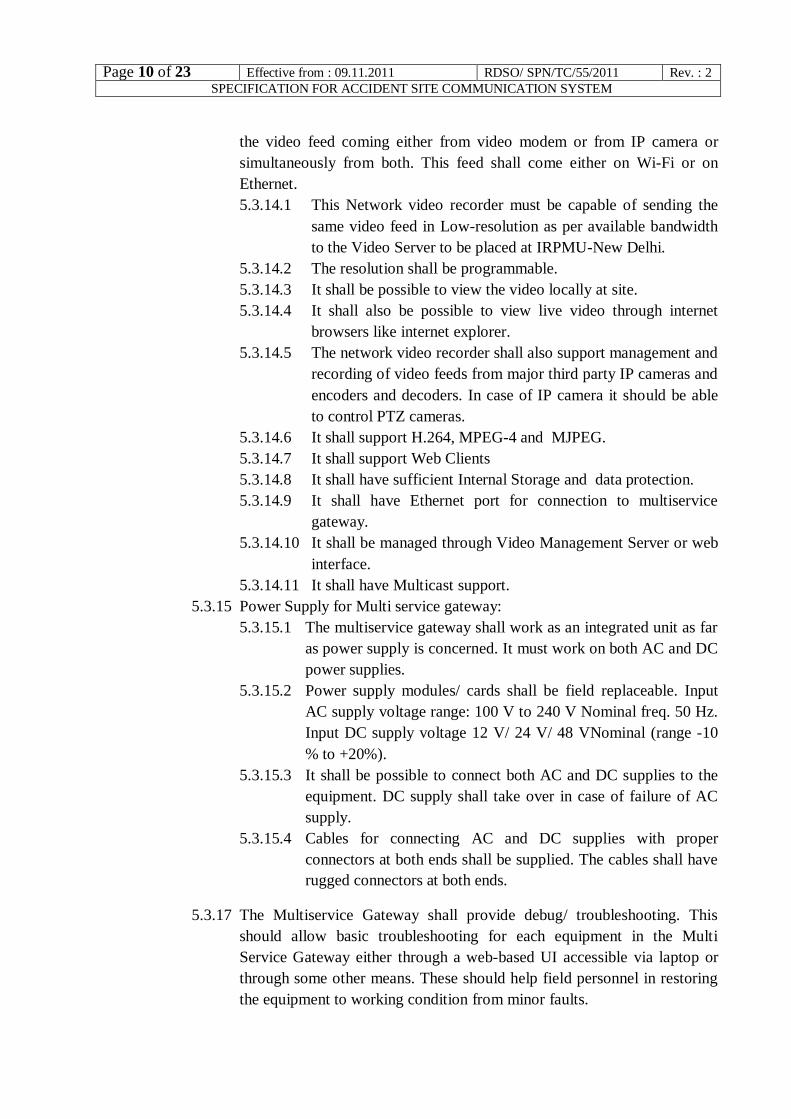
the video feed coming either from video modem or from IP camera or
simultaneously from both. This feed shall come either on Wi-Fi or on
Ethernet.
5.3.14.1 This Network video recorder must be capable of sending the
same video feed in Low-resolution as per available bandwidth
to the Video Server to be placed at IRPMU-New Delhi.
5.3.14.2 The resolution shall be programmable.
5.3.14.3 It shall be possible to view the video locally at site.
5.3.14.4 It shall also be possible to view live video through internet
browsers like internet explorer.
5.3.14.5 The network video recorder shall also support management and
recording of video feeds from major third party IP cameras and
encoders and decoders. In case of IP camera it should be able
to control PTZ cameras.
5.3.14.6 It shall support H.264, MPEG-4 and MJPEG.
5.3.14.7 It shall support Web Clients
5.3.14.8 It shall have sufficient Internal Storage and data protection.
5.3.14.9 It shall have Ethernet port for connection to multiservice
gateway.
5.3.14.10 It shall be managed through Video Management Server or web
interface.
5.3.14.11 It shall have Multicast support.
5.3.15 Power Supply for Multi service gateway:
5.3.15.1 The multiservice gateway shall work as an integrated unit as far
as power supply is concerned. It must work on both AC and DC
power supplies.
5.3.15.2 Power supply modules/ cards shall be field replaceable. Input
AC supply voltage range: 100 V to 240 V Nominal freq. 50 Hz.
Input DC supply voltage 12 V/ 24 V/ 48 VNominal (range -10
% to +20%).
5.3.15.3 It shall be possible to connect both AC and DC supplies to the
equipment. DC supply shall take over in case of failure of AC
supply.
5.3.15.4 Cables for connecting AC and DC supplies with proper
connectors at both ends shall be supplied. The cables shall have
rugged connectors at both ends.
5.3.17 The Multiservice Gateway shall provide debug/ troubleshooting. This
should allow basic troubleshooting for each equipment in the Multi
Service Gateway either through a web-based UI accessible via laptop or
through some other means. These should help field personnel in restoring
the equipment to working condition from minor faults.
Page 11 of 23 Effective from : 09.11.2011 RDSO/ SPN/TC/55/2011 Rev. : 2
SPECIFICATION FOR ACCIDENT SITE COMMUNICATION SYSTEM SYSTEMSYSTEMSYSSYSTEMSYSYSSYSYSTEM
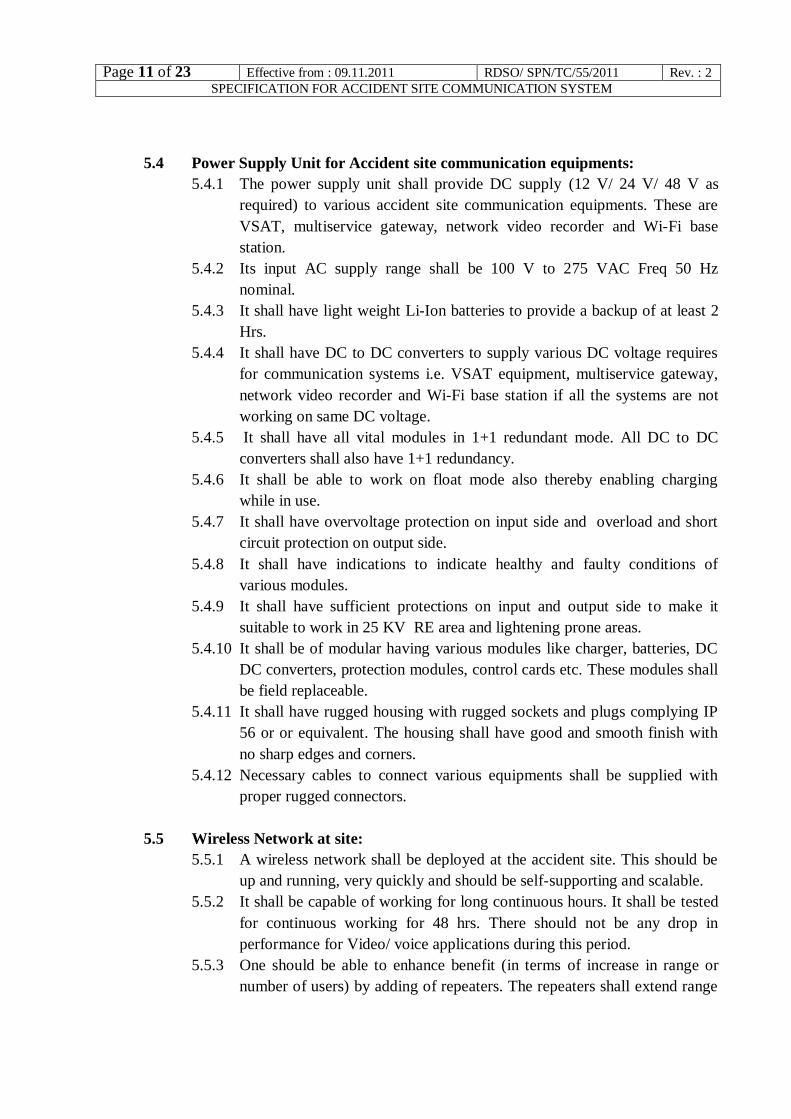
5.4 Power Supply Unit for Accident site communication equipments:
5.4.1 The power supply unit shall provide DC supply (12 V/ 24 V/ 48 V as
required) to various accident site communication equipments. These are
VSAT, multiservice gateway, network video recorder and Wi-Fi base
station.
5.4.2 Its input AC supply range shall be 100 V to 275 VAC Freq 50 Hz
nominal.
5.4.3 It shall have light weight Li-Ion batteries to provide a backup of at least 2
Hrs.
5.4.4 It shall have DC to DC converters to supply various DC voltage requires
for communication systems i.e. VSAT equipment, multiservice gateway,
network video recorder and Wi-Fi base station if all the systems are not
working on same DC voltage.
5.4.5 It shall have all vital modules in 1+1 redundant mode. All DC to DC
converters shall also have 1+1 redundancy.
5.4.6 It shall be able to work on float mode also thereby enabling charging
while in use.
5.4.7 It shall have overvoltage protection on input side and overload and short
circuit protection on output side.
5.4.8 It shall have indications to indicate healthy and faulty conditions of
various modules.
5.4.9 It shall have sufficient protections on input and output side to make it
suitable to work in 25 KV RE area and lightening prone areas.
5.4.10 It shall be of modular having various modules like charger, batteries, DC
DC converters, protection modules, control cards etc. These modules shall
be field replaceable.
5.4.11 It shall have rugged housing with rugged sockets and plugs complying IP
56 or or equivalent. The housing shall have good and smooth finish with
no sharp edges and corners.
5.4.12 Necessary cables to connect various equipments shall be supplied with
proper rugged connectors.
5.5 Wireless Network at site:
5.5.1 A wireless network shall be deployed at the accident site. This should be
up and running, very quickly and should be self-supporting and scalable.
5.5.2 It shall be capable of working for long continuous hours. It shall be tested
for continuous working for 48 hrs. There should not be any drop in
performance for Video/ voice applications during this period.
5.5.3 One should be able to enhance benefit (in terms of increase in range or
number of users) by adding of repeaters. The repeaters shall extend range
Page 12 of 23 Effective from : 09.11.2011 RDSO/ SPN/TC/55/2011 Rev. : 2
SPECIFICATION FOR ACCIDENT SITE COMMUNICATION SYSTEM SYSTEMSYSTEMSYSSYSTEMSYSYSSYSYSTEM
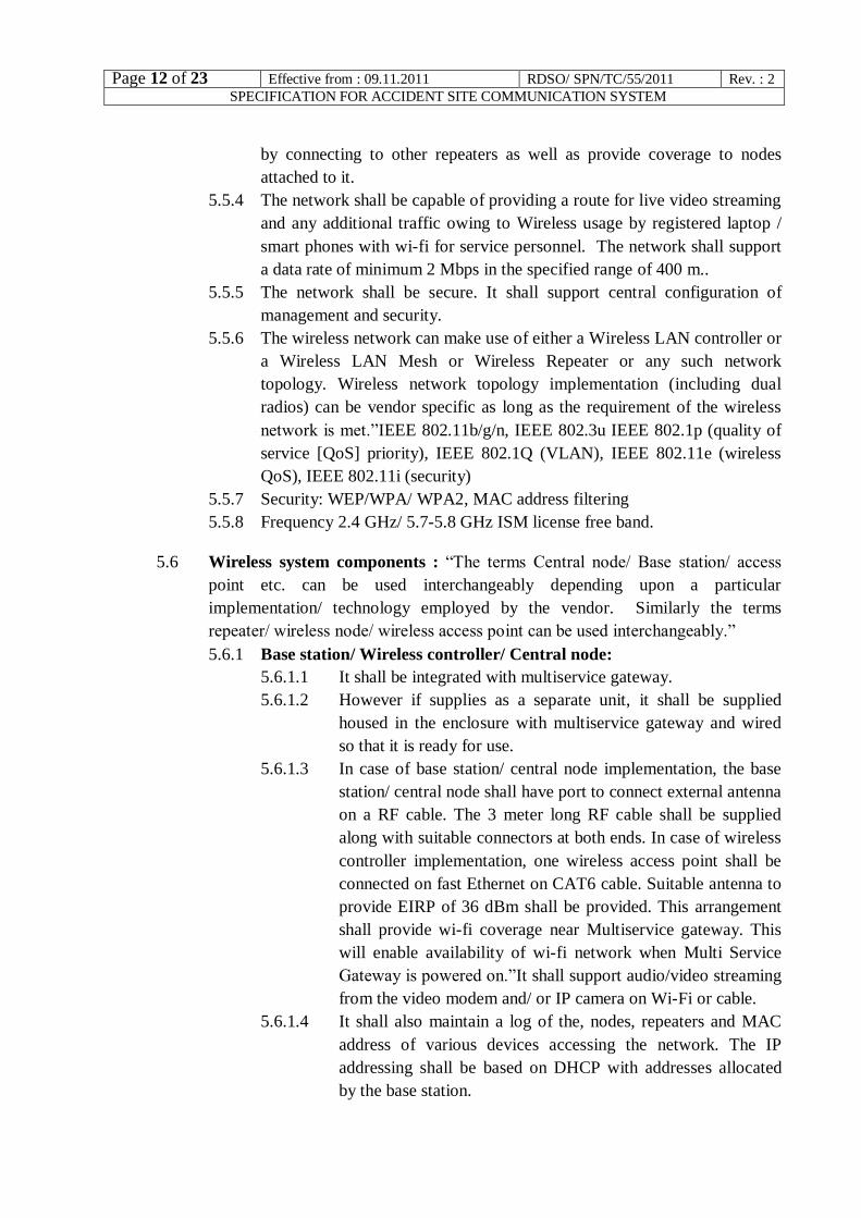
by connecting to other repeaters as well as provide coverage to nodes
attached to it.
5.5.4 The network shall be capable of providing a route for live video streaming
and any additional traffic owing to Wireless usage by registered laptop /
smart phones with wi-fi for service personnel. The network shall support
a data rate of minimum 2 Mbps in the specified range of 400 m..
5.5.5 The network shall be secure. It shall support central configuration of
management and security.
5.5.6 The wireless network can make use of either a Wireless LAN controller or
a Wireless LAN Mesh or Wireless Repeater or any such network
topology. Wireless network topology implementation (including dual
radios) can be vendor specific as long as the requirement of the wireless
network is met.”IEEE 802.11b/g/n, IEEE 802.3u IEEE 802.1p (quality of
service [QoS] priority), IEEE 802.1Q (VLAN), IEEE 802.11e (wireless
QoS), IEEE 802.11i (security)
5.5.7 Security: WEP/WPA/ WPA2, MAC address filtering
5.5.8 Frequency 2.4 GHz/ 5.7-5.8 GHz ISM license free band.
5.6 Wireless system components : “The terms Central node/ Base station/ access
point etc. can be used interchangeably depending upon a particular
implementation/ technology employed by the vendor. Similarly the terms
repeater/ wireless node/ wireless access point can be used interchangeably.”
5.6.1 Base station/ Wireless controller/ Central node:
5.6.1.1 It shall be integrated with multiservice gateway.
5.6.1.2 However if supplies as a separate unit, it shall be supplied
housed in the enclosure with multiservice gateway and wired
so that it is ready for use.
5.6.1.3 In case of base station/ central node implementation, the base
station/ central node shall have port to connect external antenna
on a RF cable. The 3 meter long RF cable shall be supplied
along with suitable connectors at both ends. In case of wireless
controller implementation, one wireless access point shall be
connected on fast Ethernet on CAT6 cable. Suitable antenna to
provide EIRP of 36 dBm shall be provided. This arrangement
shall provide wi-fi coverage near Multiservice gateway. This
will enable availability of wi-fi network when Multi Service
Gateway is powered on.”It shall support audio/video streaming
from the video modem and/ or IP camera on Wi-Fi or cable.
5.6.1.4 It shall also maintain a log of the, nodes, repeaters and MAC
address of various devices accessing the network. The IP
addressing shall be based on DHCP with addresses allocated
by the base station.
Page 13 of 23 Effective from : 09.11.2011 RDSO/ SPN/TC/55/2011 Rev. : 2
SPECIFICATION FOR ACCIDENT SITE COMMUNICATION SYSTEM SYSTEMSYSTEMSYSSYSTEMSYSYSSYSYSTEM
5.6.1.5 The unit shall have web based user interface and can be
controlled locally and remotely for its operation.
5.6.1.6 Should allow connection of authorized Wi-Fi devices like
laptop, wireless access points, wireless video modem, IP
camera, Wi-Fi phones etc. to be able to use the network. It
should be able to prevent unauthorized access of rogue access
points and user
5.6.1.7 Should do automatic channel and power setting for access
points and repeaters
5.6.1.8 It shall show deployment of connected repeaters in the form of
graph or otherwise.
5.6.1.9 Should support mobility of users/devices across the wi-fi
network. There should not be any delay or drop in performance
of video and voice during switchover.
5.6.1.10 RF power can be increased in combination with antenna to
36dBm EIRP
5.6.1.11 Range: 400 m for base station node (In line of sight) or
between adjacent APs/ Repeaters.
5.6.1.12 EMC: IEC 61000 or equivalent EN, CISPR 22 Class A or
equivalent EN or EN 301 489-1 and FCC part 15.107, 15.109
5.6.1.13 It shall support connection of one repeater on CAT 6 cable on
Ethernet port. This will enable placing two repeaters on either
side of the track to ensure availability of network even if the
other side is obstructed by the train. Similar arrangement shall
be possible with wireless access point also. Power supply for
this repeater/ access point shall be through PoE. In case of
requirement of PoE+, adaptor to drive power over ethernet to
be provided. This adopter shall be suitable for outdoor use. The
other antenna/ access point is covered in clause 5.6.1.3.”
5.6.2 Outdoor - Wireless Repeaters/ Wireless Access Points:
5.6.2.1 These will be wireless, scalable interconnected nodes. These
could be a mesh network or interconnected intelligent nodes
which can route traffic to the base station with guaranteed QoS.
5.6.2.2 RF power can be increased to 36dBm EIRP Ad-Hoc or
infrastructure mode.
5.6.2.3 Should support both Omni directional as well as directional
antenna
5.6.2.4 Management: via http/ web user interface.
5.6.2.5 Each repeater/ wireless access point should be portable and
self-sufficient having Li-Ion battery for ease in deployment and
recovery.
Page 14 of 23 Effective from : 09.11.2011 RDSO/ SPN/TC/55/2011 Rev. : 2
SPECIFICATION FOR ACCIDENT SITE COMMUNICATION SYSTEM SYSTEMSYSTEMSYSSYSTEMSYSYSSYSYSTEM
5.6.2.6 Battery shall be of sufficient capacity to give backup of 5 Hrs.
5.6.2.7 Every equipment with battery should have one spare battery
with equal capacity. External chargers shall be provided to
charge extra batteries to enable replacement of discharged
batteries at site.
5.6.2.8 EMC: IEC 61000 or equivalent EN, CISPR 22 Class A or
equivalent EN or EN 301 489-1 and FCC part 15.107, 15.109.
5.6.2.9 Ingress protection for repeaters/ access points: IP 65 or
equivalent
5.6.3 Antenna & Portable Tripod specifications:
5.6.3.1 Antennas shall be omni-directional / Sectoral to provide EIRP
of upto 36 dBm in combination with Wi-Fi radio.
5.6.3.2 Antenna impedance 50 ohms.
5.6.3.3 Portable tripods shall be supplied with antennas/APs on which
they shall be mounted.. The height of the tripod shall be
adjustable so that the height could be increased to 8 ft. It shall
be possible to reduce the height of tripod to enable easy storage
occupying less space. The tripod shall be able to take load of
antenna. The tripod shall have mounting arrangement for Wi-Fi
radio and antenna. It shall be possible to use tripod on uneven
ground also.
5.6.3.4 The length of the antenna should not be such that portability
and physical stability is compromised. The arrangement shall
be stable in windy conditions.
5.6.3.5 Suitable for outdoor use.
5.6.4 Video Modem with Wi-Fi and battery :
5.6.4.1 Video modem, outdoor Wi-Fi unit with suitable antenna and
battery to be mounted in a backpack for transportability. The
total weight shall not compromise portabilityon backpack. The
backpack shall be rainwater proof. Video modem with built-in
Wi-Fi features is preferable.
5.6.4.2 Battery shall be required for the video modem. It shall support
continuous operation of video modem and Wi-Fi unit for at-
least 3 Hrs. There shall be indication for fully charged status of
the battery. Also audio and visual indication regarding
discharged condition of the battery shall be provided.
5.6.4.3 Battery charger for this battery should work on 100 to 240
VAC 50 Hz nominal frequency.
5.6.4.4 There shall be 2 sets of spare batteries with offline charger.
Page 15 of 23 Effective from : 09.11.2011 RDSO/ SPN/TC/55/2011 Rev. : 2
SPECIFICATION FOR ACCIDENT SITE COMMUNICATION SYSTEM SYSTEMSYSTEMSYSSYSTEMSYSYSSYSYSTEM
5.6.4.5 The Wi-Fi radio along with antenna shall be capable of
providing EIRP of 30dBm. The antenna height may be
adjustable by suitable arrangement to achieve maximum height
to realize better gain. It shall be IP 65 or equivalent compliant.
5.6.4.6 The Wi-fi radio shall seamlessly work with the wireless
network created at site using access points/ repeaters provided
in this specification..
5.6.4.7 Connectivity between video modem and multiservice gateway
shall be provided through cable also in addition to wifi
connectivity. Suitable cable of length 90 meters with suitable
rugged connectors shall be provided.
5.6.4.8 Video Modem specification:
5.6.4.8.1 Compression: H.264 / MPEG-4
5.6.4.8.2 Video Resolution: 640/480, 320/240, 160/120
5.6.4.8.3 Video Frame Rate: 5-30fps
5.6.4.8.4 Video bitrate: 200 kbps to 1 Mbps
5.6.4.8.5 Network protocols: RTP, UDP, TCP, IP, HTTP,
IGMP, ICMP, SNMP, DHCP, NTP
5.6.4.8.6 Software upgrade: Flash ROM, Remote
Programmable
5.6.4.8.7 Configuration: Web based.
5.6.4.8.8 Video Input: Analog Composite PAL and should be
compatible with the Video camera. Necessary cables
and adaptors should be provided.
5.6.4.8.9 Audio In: Compatible with the video camera.
5.6.4.8.10 Overlay: Time stamp and text description
5.6.4.8.11 Ethernet port: 10/100 BaseT Fast Ethernet, Auto
Sensing. full Duplex RJ45
5.6.4.8.12 IP Multicast support
5.6.4.8.13 EMC: IEC 61000 or equivalent EN, CISPR 22
Class A or equivalent EN.
5.6.4.9 Ingress protection for video modem and wi fi unit: IP 65 or
equivalent.
5.6.5 Camera specification/ features: Camera shall have following parameters.
5.6.5.1 HD Video Codec: MPEG4-AVC/H.264
5.6.5.2 SD Video Codec: MPEG2 or better.
5.6.5.3 Media Storage Capacity: Atleast 64 GB
5.6.5.4 Image Sensor: CMOS Sensor
5.6.5.5 Colour Viewfinder: Rotatable
5.6.5.6 Optical / Digital Zoom: 25x / 300x
5.6.5.7 USB Terminal: USB 2.0 High Speed
Page 16 of 23 Effective from : 09.11.2011 RDSO/ SPN/TC/55/2011 Rev. : 2
SPECIFICATION FOR ACCIDENT SITE COMMUNICATION SYSTEM SYSTEMSYSTEMSYSSYSTEMSYSYSSYSYSTEM
5.6.5.8 Interface: A/V compatible with video modem.
5.6.5.9 Image Stabilization
5.6.5.10 Quick Autofocus
5.6.5.11 Quick Startup feature enabling camera on and camera off by
opening and closing of view finder panel.
5.6.5.12 Accessories: AC adaptor, two additional rechargeable Battery
Packs, external charger, Component Video Cable, AV Cable,
USB Cable, carrying case, tripod with adjustable height and
weight less than 1.5 kg. The accessories shall be those which
are offered by OEM of the camera.
5.6.6 Rugged Laptop: Minor variation from the parameters given below shall
be acceptable. The following are minimum requirement, however if higher
parameters are required for satisfactory functioning (like configuration,
provisioning etc.) at site with respect to various equipments supplied, the
same shall be supplied.
5.6.6.1 The laptop shall be suitable for various configuration required
to be done. It may also be used for viewing and recording live
video stream being transmitted to the video server. It shall be
loaded with necessary software. One set of DVDs containing
all the software loaded in laptop shall be provided for recovery
purpose.
5.6.6.2 The laptop shall be of reputed band like Dell, Toshiba, HP,
Panasonic, Sony etc. It shall have following minimum
configuration: Processor: Intel core i3, Operating system:
Windows 7 Professional 32 bit, , Memory 4.0 GB DDR3
SDRAM, HDD: 250 GB, Optical device: 8xDVD RW,
wireless LAN, with carrying handle, carrying case, AC adapter,
Interfaces: USB, Network 10/100 base T RJ 45, Li-Ion
batteries, Video card: as required for various configurations
and video applications in this spec.
5.6.6.3 The laptop shall be semi rugged with following features.
5.6.6.3.1 Tough outer casing
5.6.6.3.2 Water Resistant Keyboard
5.6.6.3.3 Sunlight Readable LCD Screen
5.6.6.3.4 Shock-mounted Removable HDD
5.6.6.3.5 Vibration, Drop and Shock Resistant Build
5.6.6.3.6 Storage : -15 to 70 °C
5.6.6.3.7 Humidity 5% to 95 % non condensing.
5.6.6.4 The compliance of above shall be as per international standards.
Page 17 of 23 Effective from : 09.11.2011 RDSO/ SPN/TC/55/2011 Rev. : 2
SPECIFICATION FOR ACCIDENT SITE COMMUNICATION SYSTEM SYSTEMSYSTEMSYSSYSTEMSYSYSSYSYSTEM
5.7 CAT 6 Cable: CAT 6 cable wherever required shall be supplied from reputed
manufacturer. The cables shall conform to ANSI/TIA/EIA-568-B.2-10.
6.0 Divisional HQ equipments:
6.1 Multi Service gateway for Divisional HQ:
6.1.1 It shall be fully compatible with the Multi Service gateway provided at
Accident site.
6.1.2 It shall be IP based and shall support open protocols including SIP.
6.1.3 It should have fast Ethernet port connectivity either integrated or as
standalone unit integrated within the enclosure and should have full IPV4
and IPV6 support with unicast and multicast switching and routing (for
example, native support of IGMPv3). Also it should support advanced
quality of services (QOS) to support critical applications like live video
streaming
6.1.4 It must be modular in design with flexible configuration for easy extension
of capacity by adding suitable module.
6.1.5 The system programming shall be based on GUI tool for easy
configuration and also remote configuration with built in http server.
6.1.6 The unit shall be 19” rack mountable.
6.1.7 It shall have the following interfaces:
6.1.7.1 Auto sensing duplex 10/100Mbps base TX Ethernet ports with
PoE support: Minimum 4 Numbers. Out of these ports, 2 ports
shall be WAN ports if router is included as part of Multi service
gateway.
6.1.7.2 FXO ports: 12 Numbers to connect 4 Railway telephones, 4
BSNL/ MTNL telephones and 4 hot lines. It shall be possible to
configure these for hot line and auto telephones.
6.1.7.3 The numbering scheme for FXS/ FXO ports shall support
working of Railway and BSNL/ MTNL phones with STD.
6.1.7.4 It should be possible to deploy SIP Phones, Wireless IP Phones,
Wi-Fi enabled smart phones in future in this platform as an
alternate to analog phone which is used today
6.1.8 Power Supply:
6.1.8.1 Redundant power supply for critical component like L3 switch/
router.
6.1.8.2 Working on DC supply in the range : (-) 48 V DC nominal
(range -10% to + 20%)
6.1.9 It shall support following protocols related to TCP/IP suit: IPv4, IPv 6,
TCP, UDP, RTP,RTCP, ICMP, HTTP, ARP, OSPF, IGMP v3,
NAT/PAT, NTP
6.1.10 It shall support Ethernet, 802.1q, 802.1p.
6.1.11 QoS: Differentiated Services as per latest relevant RFC.
Page 18 of 23 Effective from : 09.11.2011 RDSO/ SPN/TC/55/2011 Rev. : 2
SPECIFICATION FOR ACCIDENT SITE COMMUNICATION SYSTEM SYSTEMSYSTEMSYSSYSTEMSYSYSSYSYSTEM
6.1.12 EMC: IEC 61000 or equivalent EN or IEC 62236-4:2008- Part 4,
CISPR 22 Class A or equivalent EN .
6.1.13 It shall support various compression standards including ITU T G.711A
law, G.729, G 723.1 and iLBC.
6.1.14 It shall have features to ensure good quality voice using VoIP on
satellite link, like echo cancellation, silence suppression, Voice activity
detection (VAD) and Comfort Noise Generation (CNG).
6.1.15 IP Multicast support
7.0 Equipment in VSAT Hub: Video server for video archival and Retrieval:
7.1 All video streams transmitted from the accident site equipments, will be archived
at a centralized server located at the VSAT hub at IRPMU. It shall provide a GUI
for configuration, management and monitoring.
7.2 It shall record video from commonly used video codec/NVR/IP Cameras
7.3 The playback shall be on Window based/ Linux based/ Mac computers using web
based interface
7.4 The centralized server will be a rack mounted server grade machine.
7.5 The server stores all streams with tagging for (a) source identifier of the video b)
time-stamp of the video (c) location identifier of the video (d) any other parameter
to classify/ease searching.
7.6 It shall be possible to view the live video streams in real time at divisional, zonal
or Railway board using a browser and using any of the commonly available media
player like window media player, VLC player etc.
7.7 It shall have live streaming and on-demand playback capabilities. Streaming
capabilities: Live and on-demand streaming, up to 20 on demand and live
viewers.
7.8 The server shall not requireany manual intervention to start recording when any of
the sites starts video streaming.
7.9 Advance Search tools: Searches for both exact matches and variants of the search
form and returns results by relevance and date. Searches titles, tags and
descriptions.
7.10 User access control: Security-based profiles include administrator and authorised
viewer.
7.11 Export video sequences to external storage.
7.12 It will also be possible to view old archived footage from the stored video using
the identifiers from any location.
7.13 All video streams will be stored in a highly compressed H.264/MPEG4 format for
efficient storage in terms of space and speed of access.
7.14 The storage will be done on a rack mounted Network Attached Storage box.
7.15 The media server should be configured such that whenever any of the remote
video streaming unit gets activated and starts sending in data, the server should
start storing its content without any active intervention. The entire process should
Page 19 of 23 Effective from : 09.11.2011 RDSO/ SPN/TC/55/2011 Rev. : 2
SPECIFICATION FOR ACCIDENT SITE COMMUNICATION SYSTEM SYSTEMSYSTEMSYSSYSTEMSYSYSSYSYSTEM
be automated. The nomenclature of recorded file names should follow a logical
method and should support some form of tagging from the operator/supervisor to
aid in file retrieval. The entire process should be documented clearly.
7.16 It shall allow monitoring and recording of at least 10 simultaneous video streams.
7.17 Also should support recording in lower resolution for the available bit rate like
400kbps, 270kbps, etc
7.18 Security: System administrator controls the number of client users and their
access levels. Every client user shall be required a username and a password. Log
system shall record the user location, log on time and the duration of
communication.
7.19 Specification for NAS:
7.19.1 The Network Attached Storage (NAS) box will contain multiple hard
disks to store videos.
7.19.2 The hard disks in the NAS will be hot-swappable (replaced without
shutting down the system).
7.19.3 The NAS will provide high availability and high reliability for the
content storage. The hard disks will be configured in RAID 5/6
configuration to provide redundancy and protection against hard disk
failures.
7.19.4 The hardware RAID controller will also facilitate faster access to the
data. Effective usable NAS storage capacity will be 2TB.
7.19.5 A periodic backup facility in tape drive, DVD, or any similar format
should be possible for long term storage.
7.19.6 NAS server specification: These are minimum specification. However
if the server software requires higher specification, the same shall be
supplied.
7.19.6.1 Processor Type: Xeon (55xx/56 xx)
7.19.6.2 Processors : 2
7.19.6.3 RAM: 8 GB DDR3
7.19.6.4 Form factor: Rack mounted 2 U
7.19.6.5 NIC: Dual Gigabit Ethernet.
7.19.6.6 Power supply : Redundant
7.19.6.7 Total storage: 6 x 2 TB
7.19.6.8 Hardware RAID: RAID 5/6
7.19.6.9 Drives supported: 6
7.20 Video server specification: These are minimum specification. However if the
server software requires higher specification, the same shall be supplied.
7.20.1 Processor: Intel Xeon 3400 series or better
7.20.2 RAM : Upto 16 GB, DDR3 (1333 MHz)
7.20.3 Form factor: Rack Mounted.
7.20.4 NIC: Dual Gigabit Ethernet
7.20.5 Internal capacity: Upto 4 TB
Page 20 of 23 Effective from : 09.11.2011 RDSO/ SPN/TC/55/2011 Rev. : 2
SPECIFICATION FOR ACCIDENT SITE COMMUNICATION SYSTEM SYSTEMSYSTEMSYSSYSTEMSYSYSSYSYSTEM
7.20.6 OS Support: Microsoft windows Server or Linux compatibility (with
respect to Drivers, software)
7.20.7 Redundant power supply.
7.21 Rack for server and NAS: The rack shall be from a reputed manufacturer with
following specifications given below.
7.21.1 Basic Frame: Steel folded
7.21.2 Construction: Welded
7.21.3 Top & Bottom Cover: Bolted to Frame with Cable entry exit cut
outs
7.21.4 Front Door: Lockable Perforated steel Door
7.21.5 Rear Door: Lockable Steel Door perforated
7.21.6 19” Mounting Angle: Formed Steel
7.21.7 Std. Equipment Mounting: DIN Std. 10 mm Sq. Slots
7.21.8 Standard Finish: Powder coated
7.21.9 Standard Colour: Grey & Off white OR Black
7.21.10 Standard Mounting: Caster wheels (2 with Brake & 2 without
Brake)
7.21.11 Rack Standard: Conforms to DIN 41494/ IEC 60297 or equivalent
standard
7.21.12 Static Load 750 Kg with casters
7.21.13 Size: Usable height 42U, Usable width 19”, Usable depth 1100mm.
7.21.14 Cable Management
7.21.15 Any other arrangement required for proper fixing of NAS server and
Video server shall be provided.
8.0 Specification for Rugged Enclosure for housing Multiservice gateway for
accident site, Network video recorder, Wi-Fi base unit are as follows.
8.1 The enclosure shall have suitable arrangement for connecting various cables
as required at site. The enclosure shall be suitable for outdoor use after
connecting these cables and provide Ingress protection as per IP 55 or NEMA
4. Any ports which are exposed to outside shall be provided with IP 65
connectors.
8.2 Design of the enclosure shall be such that it shall not obstruct easy connection
of power supply and other cables.
8.3 It shall have good smooth finish with no sharp edges.
8.4 Indications of various devices housed inside shall be clearly visible. Any
transparent material used for such purpose shall be scratch proof.
8.5 Only passive cooling methods to be used.
8.6 Mounts should be shock and vibration absorbent.
Page 21 of 23 Effective from : 09.11.2011 RDSO/ SPN/TC/55/2011 Rev. : 2
SPECIFICATION FOR ACCIDENT SITE COMMUNICATION SYSTEM SYSTEMSYSTEMSYSSYSTEMSYSYSSYSYSTEM
9.0 Specification for connecting cable connectors (like RJ 45): The connectors supplied shall
be suitable for outdoor use and shall be able to take load of long cables as required in this
specification. The connectors shall conform to IP 65 or equivalent.
10.0 Environmental parameters:
10.1 Accident site equipments (i.e. Multi Service gateway for accident site, Wi-Fi
base station/ controlleer, repeaters/ access point, Network video recorder, video
modem and power supply unit) shall be rugged for transport by train and suitable
for outdoor use. They can also be ruggedized using appropriate enclosure.
10.2 The above mentioned accident site equipments shall meet following
environmental parameters. These requirements can be met with or without use of
special enclosures.
10.2.1 Opeartional temperature: 0 to 55°C
10.2.2 Operational Humidity Upto 95% Non condensing.
10.2.3 Storage temperature range : -15°C to 70°C
10.3 The equipment shall be tested for following parameters as per IS 9000 or any
other international standards. (Alternatively the equipments can be supplied
enclosed in a ruggedized enclosure. In that case the equipments shall be tested
while they are housed in the enclosure)
10.3.1 Dry Heat Test
10.3.2 Cold test
10.3.3 Damp heat Test (Cyclic): upper temp 40°C Humidity 95%
10.3.4 Damp heat test (steady state storage): 40°C Humidity 95%
10.3.5 Dust test:
10.3.6 Driving rain test:
10.3.7 Bump test (For clause 14.2 only): The equipment in packed condition
inside containers shall be subject to bump test for 1000 Bumps, peak
acceleration 40m/s2, pulse duration 6 ms, no of axes 3
10.3.8 Vibration Test: Amplitude ± 6 mm, constant displacement or 15m/Sec.2
constant acceleration. No. of axes 3, No of sweep cycle 20, Total duration
105 min.
10.4 The multiservice gateway for divisional HQ shall be suitable for working in
temperature range of 0 to 40°C
11.0 TESTS AND PERFORMANCE OF REQUIREMENT :
11.1 The System Provider shall submit detailed brochures/ user manuals/ test
certificates of various equipments proposed to be used, covering the parameters as
given in Functional Requirements, Technical Requirements, Climatic
Requirements, Vibration & Shock Requirements and EMI & EMC requirements
of this specification.
Page 22 of 23 Effective from : 09.11.2011 RDSO/ SPN/TC/55/2011 Rev. : 2
SPECIFICATION FOR ACCIDENT SITE COMMUNICATION SYSTEM SYSTEMSYSTEMSYSSYSTEMSYSYSSYSYSTEM
11.2 In case Purchaser so desire any other test on the equipment shall be conducted by
System Provider in presence of Purchaser’s Representative to ascertain
conformance.
11.3 At-least one equipment of each type should be tested for functional parameter by
System Provider in presence of Purchaser’s Representative. The tests shall be
conducted as per Test Procedure proposed by manufacturer duly reviewed and
approved by Purchaser.
11.4 The equipments tested as above shall be integrated to form one complete system
by System Provider to demonstrate the workability of complete integrated system
as an initial demonstration.
11.5 Once the workability of system has been proved as above, further supplies can be
made by System Provider in consultation with Purchaser.
12.0 INSTRUCTION BOOKS/MANUALS, MEASURING INSTRUMENTS & SPARES. 12.1 System Provider shall submit following documents for each Sub-System/Module
as supplied by Sub-System Provider/Manufacturer along-with each System. These
documents shall be submitted in 2(two) Hard Copy and 1(one) CD.
12.1.1 Operating Instruction Manual
12.1.2 Maintenance & Troubleshooting
12.1.3 Manual Technical Manual
12.2 System Provider shall submit complete details of the Test & Measuring
Equipments required for Testing & Servicing to Purchaser.
12.3 System Provider shall submit a list of the recommended spares for a period of
5(five) years to Purchaser.
13.0 Recommended supply list. The following equipments which are covered in this
specification shall make the recommended supply list for one system:
13.1 Multi service Gateway for accident site 1 No with 100 % spare power supply
module/ cards for its various systems/ subsystems.
13.2 Wi-Fi equipment consisting of base unit/ wireless controller, antennas and
repeaters:
13.2.1 Base unit/ wired access point with wireless controller : 1 No with antenna.
13.2.2 Repeater / wireless access point: 3 Numbers with antennas, batteries for
repeaters/ wireless access point: 6 Nos, Battery charger 3 Nos.
13.2.3 Tripods for mounting antenna and repeater/ access points: 4 Nos.
13.2.4 CAT cable: CAT 6 cable with RJ 45 connectors at both ends 45 meters
length for connecting base with one of the repeaters/ access point.
13.2.5 RF cable 3 meter long with suitable rugged connectors at both ends for
connecting one of the antenna to the base unit.
13.3 Portable camera with view finder and zoom facility: 1 No along with all the
accessories as mentioned in this specification.
13.4 Video modem with both Wi-Fi and cable connectivity, in portable form: One set
consisting of
13.4.1 Video modem with Wi-Fi radio and collapsible antenna: 1No.
13.4.2 Battery for video modem: 3 No, Charger for Battery: 1 No.
13.4.3 Backpack (water proof) suitable for keeping video modem and battery: 1
No.

Page 23 of 23 Effective from : 09.11.2011 RDSO/ SPN/TC/55/2011 Rev. : 2
SPECIFICATION FOR ACCIDENT SITE COMMUNICATION SYSTEM SYSTEMSYSTEMSYSSYSTEMSYSYSSYSYSTEM
13.4.4 CAT cable: CAT 6 cable with rugged RJ 45 connectors at both ends 90
meters length for connecting video modem with multiservice gateway.
13.5 Rugged laptop: 1No
13.6 Power supply unit: 1 No.
13.7 Multi service Gateway for divisional head quarter. 1 No.
13.8 Equipment at VSAT Hub - Video server with storage : Total 1 No. This
equipment shall be centralized equipment for all the field equipment irrespective
of the number of systems procured.
14.0 Containers for equipments: 14.1 Suitable containers shall be supplied for keeping these equipments.
14.2 These containers shall protect the equipments from bumps during transport. The
containers shall be tested as per clause 10.3.7.
END OF DOCUMENT