draft version 2021-04-2006-11 gads solar generation
TRANSCRIPT
NERC | Report Title | Report Date I
DRAFT VERSION 2021-04-2006-11
GADS Solar
Generation Data Reporting Instructions
Effective January 1, 2023
Date

DRAFT NERC | GADS Solar Data Reporting Instructions | March 2019 DRAFT II
Effective Date: 01/01/2022 Working Group/Committee Acceptance: GADSWG: xxx Performance Analysis Subcommittee: xxx Planning Committee: xxx

DRAFT NERC | GADS SOLAR Data Reporting Instructions | March 2019 DRAFT iii
Table of Contents
Revision History ........................................................................................................... Error! Bookmark not defined.
Preface ........................................................................................................................................................................ v
Introduction ................................................................................................................................................................1
Chapter 1 – Data Transmittal and Format ..................................................................................................................2
Transmittal ..............................................................................................................................................................2
Format .....................................................................................................................................................................2
Reporting Deadlines ................................................................................................................................................3
Chapter 2 – Plants, Groups, and Energy Storage Reporting ........................................................................................4
Plant Boundaries .....................................................................................................................................................4
Plants.......................................................................................................................................................................4
Inverter Groups .......................................................................................................................................................5
Energy Storage Group .............................................................................................................................................5
Chapter 3 – Configuration Data ..................................................................................................................................8
Plant Configuration Data .........................................................................................................................................8
Inverter Group Configuration ............................................................................................................................... 10
Energy Storage Group Configuration ................................................................................................................... 12
Chapter 4 – Performance Reporting ....................................................................................................................... 15
Inverter Group Performance Reporting ............................................................................................................... 15
Energy Storage Performance Data Layout ........................................................................................................... 31
Chapter 5 – Event Reporting ................................................................................................................................... 34
Event Detail Reporting ......................................................................................................................................... 34
Chapter 6 – Outage Detail Reporting ...................................................................................................................... 37
Appendix A – GADS SOLAR REPORTING APPLICATION Data Release Guidelines ...................................................... 39
Data Release Guidelines ...................................................................................................................................... 39
Appendix B – Entity and Inverter Group Identification ............................................................................................. 38
Entity Identification .............................................................................................................................................. 40
Getting an Entity Registration ID ............................................................................................................................ 40
Plant ID ................................................................................................................................................................. 40
Inverter Group ID ................................................................................................................................................. 40
Entity Reporter Identification ............................................................................................................................... 40
Appendix C – System Equipment Outage Code, Cause Code, and Contributing Operating Condition .................. 41
Appendix D – Terms and Definitions ........................................................................................................................ 43
Appendix E – Equations .......................................................................................................................................... 569
Appendix F – Reference Tables ............................................................................................................................... 54
DRAFTError! No text of specified style in document.
DRAFT NERC | GADS Solar Data Reporting Instructions | March 2019 DRAFT iv
Appendix G – Solar Examples .................................................................................................................................. 59
Appendix H – Outside Management Control .......................................................................................................... 62
Appendix I – Outage Classification Guidelines ........................................................................................................ 64
Appendix J – Plant, Inverter Group, and Energy Storage Ownership Status ........................................................... 71
Table of Figures Figure 1: Timeline of Reporting Deadline ...................................................................................................................3 Figure 2: Typical Solar Plant Layout ............................................................................................................................4

DRAFT NERC | GADS SOLAR Data Reporting Instructions | March 2019 DRAFT v
Preface
The North American Electric Reliability Corporation (NERC) is a not-for-profit international regulatory authority whose mission is to assure the reliability of the bulk power system (BPS) in North America. NERC develops and enforces Reliability Standards; annually assesses seasonal and long‐term reliability; monitors the BPS through system awareness; and educates, trains, and certifies industry personnel. NERC’s area of responsibility spans the continental United States, Canada, and the northern portion of Baja California, Mexico. NERC is the electric reliability organization (ERO) for North America, subject to oversight by the Federal Energy Regulatory Commission (FERC) and governmental authorities in Canada. NERC’s jurisdiction includes users, owners, and operators of the BPS, which serves more than 334 million people.
The North American BPS is divided into six Regional Entity (RE) boundaries as shown in the map and corresponding table below. The multicolored areas denote overlap as some load-serving entities participate in one Region while associated Transmission Owners/Operators participate in another.
MRO Midwest Reliability Organization
NPCC Northeast Power Coordinating Council
RF ReliabilityFirst
SERC SERC Reliability Corporation
Texas RE Texas Reliability Entity
WECC Western Electricity Coordinating Council
DRAFT NERC | GADS SOLAR Data Reporting Instructions | March 2019 DRAFT 1
Introduction
These GADS Solar Generation (GADS‐S) ‐ Data Reporting Instructions were developed to assist plant personnel in reporting information to NERC’s GADS Solar Reporting application. The instructions detail the procedures, schedule, and format to follow when reporting data. Throughout this document, the term “Entity” will be used to refer to the principal organization that owns one or more plants.
Who Must Report? Reporting of solar performance data is mandatory for all NERC registered entities with a Generator Owner function/scope that operate solar generating facilities with a Total Installed Capacity1 of 20 MW or greater per facility with commercial operation that began on January 1, 2010 or later, regardless of interconnection. The reporting instructions detail the data elements collected by GADS Solar Reporting application and have been identified by the industry as being vital to the understanding and interpretation of the performance of solar generating facilities.
Data Release Guidelines The GADS Solar Reporting Application Data Release Guidelines can be found in Appendix A.
What will be reported?
Four types of data files will be reported:
1. Configuration • Plant • Inverter Group • Energy Storage
2. Monthly Performance • Inverter Group • Energy Storage
3. Event • Plant
4. Monthly Equipment Outage Detail • Inverter Group
When will Mandatory Reporting Begin? January 1, 2023 (Data may be submitted voluntarily at an earlier date if NERC is ready to accept data) Targeting Phased-in Approach
1. Year one (Q3 and Q4 of 2022) – Voluntary Reporting (pending application development)
2. Year two (2023) – Plants with a Total Installed Capacity of 50 MW or more
3. Year three (2024) – Plants with a Total Installed Capacity of 20 MW or more
Note: Solar plants that do not meet the mandatory reporting criteria may report on a voluntary basis.
1 Total Installed Capacity is defined in Appendix D as the sum of Inverter Group Installed Capacity.

Chapter 1 – Data Transmittal and Format
DRAFT NERC | GADS Solar Data Reporting Instructions | March 2019 DRAFT 2
Chapter 1 – Data Transmittal and Format
Transmittal Four types of data files will be reported:
1. Configuration • Plant • Inverter Group • Energy Storage Group
2. Monthly Performance • Inverter Group • Energy Storage Group
3. Event • Plant
4. Monthly Component Data • Inverter Group
Configuration data contains location, environment, and other design data about the plant, inverter group, or on-site energy storage. Configuration data is required prior to reporting performance, event, and component outage data. During the initial import of configuration data, IDs will be assigned to the plant, inverter group(s), and on-site energy storage, if applicable. Event, monthly performance, and monthly component outage data are required to be reported within 45 days after the end of every calendar quarter via the GADS Solar reporting application. Templates in Excel format are provided at: (website link to be confirmed) Report this data throughout the life of each plant.
Format Data shall be submitted to NERC through the GADS Solar reporting application using the format templates available on NERC’s website at: (website link to be confirmed) or a comma-separated value (CSV) formatted file that follows the column order and fieldnames of the data reporting templates. Column headers are required for all Excel and CSV-formatted files.2 Please ensure that all fields exclude punctuation such as commas, apostrophes, etc.; a decimal point and slashes used in dates are permitted. For example, numbers with embedded commas can cause problems such as 12,000.25. In this example, the value should be reported as 12000.25. There is no required naming convention for data files. Each data type will have specific column headers and tab names that may not be changed. Multiple NERC Entity or Inverter Group IDs maybe reported within the same file.
2 CSV (Comma-Separated Values) is a common file type used to import data from one software application to another, with commas separating the values in each record.
Chapter 1 – Data Transmittal and Format
DRAFT NERC | GADS Solar Data Reporting Instructions | March 2019 DRAFT 3
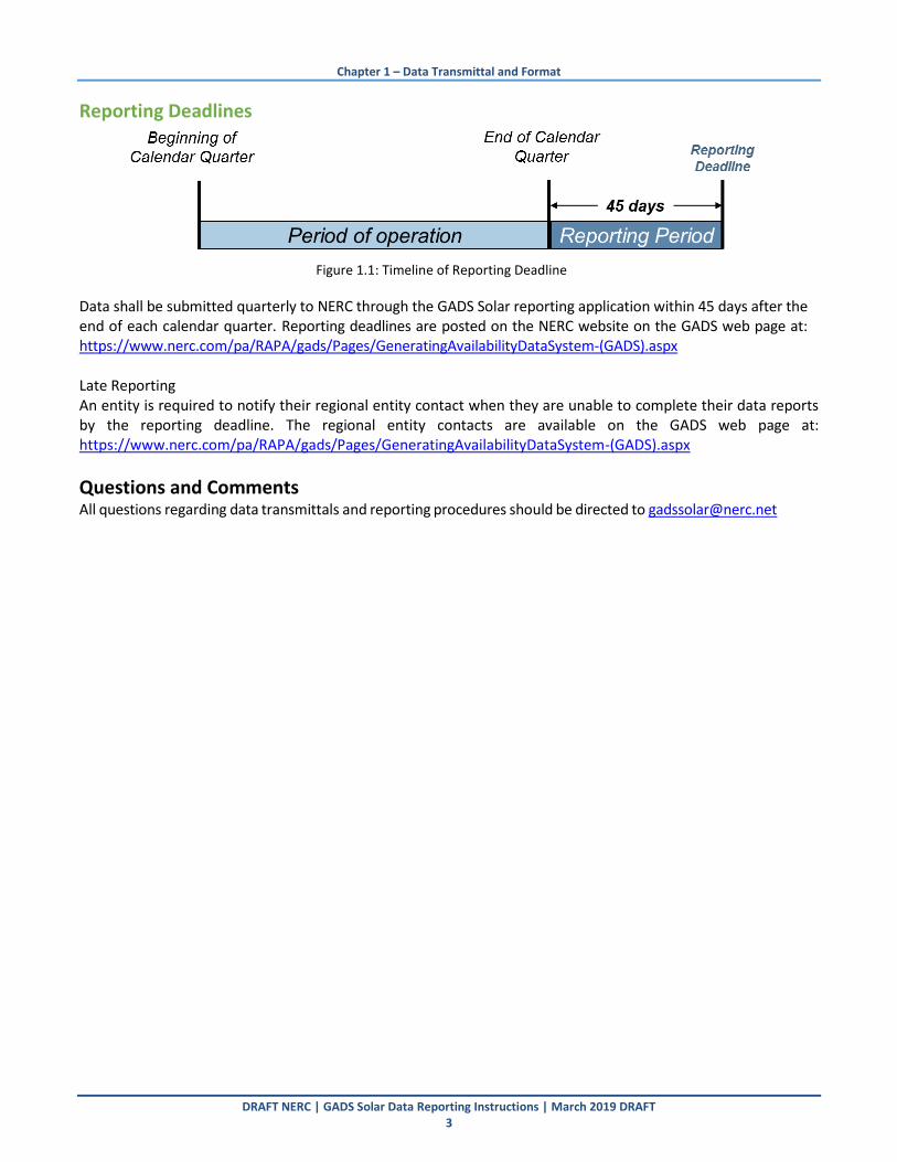
Reporting Deadlines
Figure 1.1: Timeline of Reporting Deadline
Data shall be submitted quarterly to NERC through the GADS Solar reporting application within 45 days after the end of each calendar quarter. Reporting deadlines are posted on the NERC website on the GADS web page at: https://www.nerc.com/pa/RAPA/gads/Pages/GeneratingAvailabilityDataSystem-(GADS).aspx Late Reporting An entity is required to notify their regional entity contact when they are unable to complete their data reports by the reporting deadline. The regional entity contacts are available on the GADS web page at: https://www.nerc.com/pa/RAPA/gads/Pages/GeneratingAvailabilityDataSystem-(GADS).aspx
Questions and Comments All questions regarding data transmittals and reporting procedures should be directed to [email protected]

DRAFT NERC | GADS SOLAR Data Reporting Instructions | March 2019 DRAFT 4
Chapter 2 – Plants, Groups, Energy Storage, and Solar Considerations
In Figure 1, the diagram represents a typical plant with the plant boundary at the revenue meter. Inverter Groups may represent different phases of development or physical connections of solar panels to an inverter. Although Figure 1 shows the groups as being electrically isolated, this need not be the case. A feeder may have multiple inverter types. The plant is responsible for allocating production and hourly distributions using feeder meters, inverter meters, SCADA systems, manual logs, or other means into the proper groups.
Figure 2.1: Typical Solar Plant Layout
Plant Boundaries The following describes the plant boundary in preferred order:
1. The preferred plant boundary at the revenue meter is usually at the high‐voltage terminals of the generator step‐up (GSU) transformer and the station service transformers; or
2. Utility-scale solar that meets reporting criteria with direct interconnection to the distribution system; or
3. In cases of multiple Inverter groups, the plant boundary would be at the metering of the low side of the substation transformer (load) side of the generator voltage circuit breakers; or
4. Any equipment boundary that is reasonable considering the design and configuration of the generating unit.
5. Plant definitions may not cross the boundary of a NERC region, state, province or country.
Plants A plant is defined as a collection of inverter groups at a single physical location. There may be any number of inverter groups at the solar plant. The solar plant may also have on-site energy storage.
Chapter 2 – Plants, Groups, Energy Storage, and Solar Considerations
DRAFT NERC | GADS Solar Data Reporting Instructions | March 2019 DRAFT 5
Inverter Groups An Inverter Group is a collection of solar inverters with the same manufacturer, design, system capacity, model number, and phase of construction.
Energy Storage Group An Energy Storage Group is a collection of energy storage equipment of the same technology, manufacturer, design, system capacity, model number, and phase of construction that is electrically connected to a renewable energy generating facility and installed on-site as part of the plant.
Solar Considerations
There is a difference between Solar Generation and other generators. The sun only shines during the day, so generation can only happen during specific hours of the day. This is different than conventional generation that can be started up at any time. Due to this, the Data Reporting Instructions have been set up to record statistics based on the Solar Day to measure solar site specific information, as well as statistics based on a 24 hour day to compare to conventional generators with regards to reliability. Solar Day Solar Generation can only happen during the Solar Day – defined as Sunrise to Sunset. Over the course of the month, these Solar Day hours add up to Active Solar Hours. When multiplied by the number of Inverters in an Inverter Group, these hours are recorded as Active Solar Inverter Hours in the monthly Performance Report. There are several different resources that can be used at a particular location (Latitude and Longitude) that show when sunrise and sunset occur. (such as NOAA: https://www.esrl.noaa.gov/gmd/grad/solcalc/sunrise.html) Most solar sites have a small difference between the sunrise time and the stable voltage in the inverter that would begin solar generation. (as well as the end of the day’s end of stable voltage as the sun goes down and the time of sunset.) These moments in between add up to Resource Unavailable Inverter Hours– Day in the Performance Report. For other hours during the day where the inverters are producing and sending energy to the grid, those are Service Inverter Hours – Day in the Performance Report. Planned, Maintenance, and Forced Outage Hours during the day are recorded as appropriate. If there are outages during Resource Unavailable times, the outages take precedence in reporting. At night, Service Inverter Hours- Night can be used when inverters are used as VAR support. At night, the time between sunset and sunrise can be recorded as Resource Unavailable Inverter Hours – Night unless there is some other outage in affect. Global Horizontal Irradiance Some Solar entities use an averaged per day version of Global Horizontal Irradiance, and some use a per year version. For GADS Solar reporting, Global Horizontal Irradiance will be in kWh/m2 per year. Please be careful when researching or calculating a plant’s Global Horizontal Irradiance and note how it is referenced since it can vary from one source to another. Some list the annual as an Average Annual Sum of Global Horizontal Irradiance. (In many cases Irradiance is an instantaneous measurement in KW/m2; however the value for GHI used here is in kWh/m2/year i.e. Insolation.) A comparison of locations that use one or the other is below. Describe how to calculate in appendix. NREL lists potential solar sites with Global Horizontal Irradiance figures in kWh/m2/day. https://www.nrel.gov/gis/solar.html.

Chapter 2 – Plants, Groups, Energy Storage, and Solar Considerations
DRAFT NERC | GADS Solar Data Reporting Instructions | March 2019 DRAFT 6
This is also referenced by NOAA. https://www.ncdc.noaa.gov/data-access/land-based-station-data/land-based-datasets/solar-radiation and the National Solar Radiation Database https://nsrdb.nrel.gov/nsrdb-viewer.
Global Solar Atlas lists Global Horizontal Irradiance in kWh/m2 per year. https://globalsolaratlas.info/
Solargis lists Global Horizontal Irradiance in kWh/m2 per year https://solargis.com/maps-and-gis-data/download/usa
PV Performance Modeling (Sandia National Labs) If using your own company’s reference material, please be sure to make sure proper (day vs year) numbers are reported for GADS Solar reporting. Expected Generation Expected Generation (MWh) is the calculated optimal generation that a Solar Plant can produce under measured conditions with all equipment working as expected. “Measured Conditions” means actually measured solar radiation for the reporting period. Expected Generation is the best possible generation under available conditions without any equipment issues. The IEC Weather Corrected Expected Generation is a good reference.3 This is different than Predicted Generation (such as used by PVWatts: https://pvwatts.nrel.gov/ ) that uses historical measurements of solar radiation to predict Maximum Generation in a reporting period that can also be used as to compare actual generation. NERC does not use Predicted Generation. In conventional plants, the Maximum Generation a plant can deliver is constant during the whole reporting period. Since Solar is variable throughout any particular day, this conventional method cannot be used as an accurate measure of performance In general, we can say which terms go into Expected Generation (but not limited to):
3 Reference IEC 61724 standard
Chapter 2 – Plants, Groups, Energy Storage, and Solar Considerations
DRAFT NERC | GADS Solar Data Reporting Instructions | March 2019 DRAFT 7
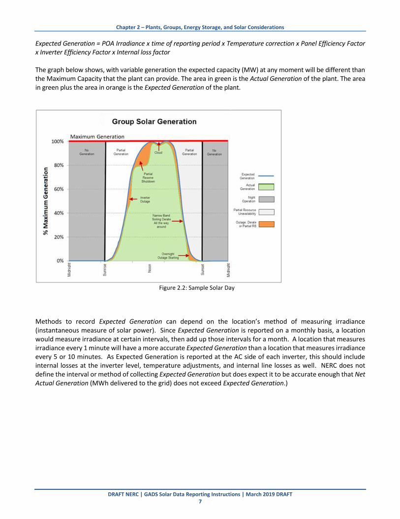
Expected Generation = POA Irradiance x time of reporting period x Temperature correction x Panel Efficiency Factor x Inverter Efficiency Factor x Internal loss factor The graph below shows, with variable generation the expected capacity (MW) at any moment will be different than the Maximum Capacity that the plant can provide. The area in green is the Actual Generation of the plant. The area in green plus the area in orange is the Expected Generation of the plant.
Figure 2.2: Sample Solar Day
Methods to record Expected Generation can depend on the location’s method of measuring irradiance (instantaneous measure of solar power). Since Expected Generation is reported on a monthly basis, a location would measure irradiance at certain intervals, then add up those intervals for a month. A location that measures irradiance every 1 minute will have a more accurate Expected Generation than a location that measures irradiance every 5 or 10 minutes. As Expected Generation is reported at the AC side of each inverter, this should include internal losses at the inverter level, temperature adjustments, and internal line losses as well. NERC does not define the interval or method of collecting Expected Generation but does expect it to be accurate enough that Net Actual Generation (MWh delivered to the grid) does not exceed Expected Generation.)

Chapter 3 – Configuration Data
DRAFT NERC | GADS Solar Data Reporting Instructions | March 2019 DRAFT 8
Chapter 3 – Configuration Data
Configuration data contains location, environment, and other design data about the plant, inverter group, or on-site energy storage. Configuration data is required prior to reporting performance, event, and component outage data. During the initial import of configuration data, IDs will be assigned to the plant, inverter group(s), and on-site energy storage group(s), if applicable. The assigned IDs remain with the plant throughout its life cycle. Configuration data may be updated at any time and must be reviewed annually. Retirements and transfer of ownership are handled through configuration data updates. NERC requests that values reported to NERC match any values that are also reported to other governmental or regulatory agencies such as the EIA, EPA, etc.
Plant Configuration Data Plant data is required. Each Plant will be assigned a unique identifier through the GADS Solar Reporting application when the Plant Configuration template is imported. Outage Event data are reported at the Plant level.
Plant Configuration Data Layout (Excel or CSV Format)
Note: The ISO Resource ID is a voluntary field used to provide an identifier assigned by an ISO/RTO market in the event that the ISO/RTO requires mandatory GADS reporting for solar plants.
Table 3.1: Plant Configuration Data Layout
Column Field Name Column Header Label Entry Type Mandatory
or Voluntary
1 Entity ID EntityID Alpha-Numeric-10 Mandatory
2 Region Region Alpha-Numeric - 8 Mandatory
3 Plant ID PlantID Numeric - 10 Mandatory
4 Plant Name PlantName Alpha‐Numeric ‐ 45 Mandatory
5 EIA Plant Code EIACode Numeric – 6 Mandatory
6 ISO Resource ID PlantISOID Alpha‐Numeric ‐ 30 Voluntary
7 Country Country Alpha‐Numeric ‐ 2 Mandatory 8 Nearest City NearCity Alpha‐Numeric ‐ 40 Mandatory 9 State/Province State Alpha‐Numeric ‐ 2 Mandatory
10 Location Latitude Latitude Numeric ‐ 3 + 4 decimals Mandatory 11 Location Longitude Longitude Numeric ‐ 3 + 4 decimals Mandatory 12 Elevation (m) Elevation Numeric ‐ 5 Mandatory
13 Solar Regime Environment SRegime Numeric ‐ 3 Mandatory
14 Global Horizontal Irradiation (kWh/m^2)
GHI Numeric – 4 + 2 decimals Mandatory
15 Inter-Annual Variance of Irradiance (%) IAVOR Numeric – 3 + 2 decimals Mandatory
16 On-site Energy Storage OnsiteStorage Yes/No Mandatory
17 Plant Ownership Status PlantOwnStatus Alpha-Numeric-2 Mandatory
18 Plant Effective Date PlantEffDate Date (mm/dd/yyyy) Mandatory
19 Plant Transfer to Entity ID PlantTransferEntity Alpha-Numeric – 10 Conditionally Mandatory

Chapter 3 – Configuration Data
DRAFT NERC | GADS Solar Data Reporting Instructions | March 2019 DRAFT 9
Table 3.2: Plant Configuration Data Descriptions
Column Field Name Description
1 Entity ID Enter the NERC Compliance Registry ID number (NCR ID) or voluntary reporting ID assigned by NERC of the organization that operates the Solar plant.
2 Region
Enter the region code for the NERC region where the Plant, Inverter Group or Energy Storage Group is located.
Use Table 16 in Appendix F to identify the correct region abbreviation.
3 Plant ID Enter the Plant ID assigned by the GADS Solar application.
4 Plant Name Enter the Plant name. This will not be assigned by NERC or the GADS Solar application.
5 EIA Plant Code Enter the EIA Plant Code of the facility as reported to EIA.
6 ISO Resource ID (Voluntary)
If applicable, enter the unique plant identifier assigned by the ISO or RTO.
7 Country Using Table 1 in Appendix F, enter the two‐letter country abbreviation where the plant is located.
8 Nearest City Enter the name of the nearest major city closest in proximity to the plant.
9 State /Province Using Table 2, 3, or 4 in Appendix F, enter the two‐letter State/Province abbreviation where the plant, group, or energy storage is located.
10 Plant Location Latitude
Enter the degrees of latitude of the physical location of the plant.4
11 Plant Location Longitude
Enter the degrees of longitude of the physical location of the plant.
12 Elevation Enter the elevation of the physical location of the plant, given in meters.
13 Solar Regime Environment
Using Table 5 in Appendix F, enter the solar regime.
14
Global Horizontal Irradiation (Insolation)
Enter the Global Horizontal Irradiation based on local calculations. With new plants, use theoretical data from available design data. (generally annual averages over at least 5 years)
For older plants, use on-site data. (generally annual averages over at least 5 years)
15 Inter-Annual Variance of GHI
Enter the Inter-Annual Variance of GHI, use location specific data.
With new plants, use theoretical data from available design data; for older plants, use on-site data.5
16 On-site Energy Storage
Indicate whether the facility has any type of energy storage that is electrically connected to a renewable energy generating facility and installed on-site as part of the plant.
17 Plant Ownership Status
Enter the ownership status of the Plant. See Appendix F, Table 15 for ownership status codes.
Plant Ownership Status is required for updates to existing configuration data; leave blank for new plants.
18 Plant Effective Date
Enter the effective date of the Plant ownership status being reported.
Effective Date is required for updates to existing configuration data; leave blank for
new plants.

Chapter 3 – Configuration Data
DRAFT NERC | GADS Solar Data Reporting Instructions | March 2019 DRAFT 10
Table 3.2: Plant Configuration Data Descriptions
Column Field Name Description
19 Plant Transfer to Entity ID
Enter the Entity ID of the Entity to which the Plant is being sold.
This is a required field when the Plant Ownership Status being reported is “Transfer.”
Inverter Group Configuration An Inverter Group is a collection of solar inverters with the same manufacturer, design, system capacity, model number, and phase of construction. Each Inverter Group will have a unique identifier assigned by NERC through the GADS Solar Reporting application. At least one Inverter Group data is required for each plant. Note: When a new Inverter Group is commissioned, the reporting obligation for that inverter group begins with the first full calendar month after the group was commissioned. Performance, event, and component outage data are reported at the Inverter Group level.
Inverter Group Configuration Data Layout (Excel or CSV Format)
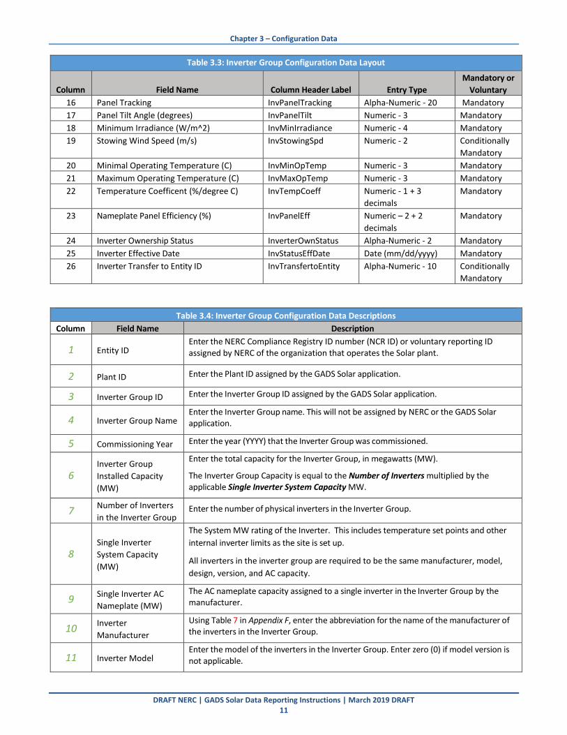
Table 3.3: Inverter Group Configuration Data Layout
Column Field Name Column Header Label Entry Type
Mandatory or
Voluntary
1 Entity ID EntityID Alpha-Numeric-10 Mandatory
2 Plant ID PlantID Numeric ‐ 10 Mandatory
3 Inverter Group ID InvGroupID Numeric ‐ 10 Mandatory
4 Inverter Group Name InvGroupName Alpha‐Numeric ‐ 45 Mandatory
5 Commissioning Year InvCommYear Numeric ‐ 4 Mandatory
6 Inverter Group Installed Capacity (Single
Inverter System Capacity * Number of
Inverters) MW
InvGrpInstCapacity Calculated Field
(Numeric ‐ 8 + 3
decimals)
Mandatory
7 Total Number of Inverters for Inverter
Group
InverterCount Numeric ‐ 7 Mandatory
8 Single Inverter System Capacity (MW) InvSystemMW
Numeric ‐ 3 + 3
decimals
Mandatory
9 Single Inverter AC Nameplate (MW) InvACCap Numeric ‐ 3 + 3
decimals
Mandatory
10 Inverter Manufacturer InvMfr Alpha‐Numeric ‐ 5 Mandatory
11 Inverter Model InvMdl Alpha‐Numeric ‐ 20 Mandatory
12 SCADA Manufacturer SCADAMfr Alpha‐Numeric ‐ 5 Mandatory
13 SCADA Model SCADAMdl Alpha Numeric - 10 Mandatory
14 DC Input Type InvDCInputType Alpha‐Numeric ‐ 20 Mandatory
15 Aggregate DC to AC Field Capacity Ratio InvDCACRatio Numeric ‐ 2 + 3
decimals
Mandatory
4 The degrees of longitude, latitude, and elevation may be taken anywhere on the site that is meaningful to the reporting entity. This could be the revenue meter, main structure, or geographic center of the Inverter Inventory. 5 (Generally 5 years of data is needed for annual standard deviation of irradiance.) GHI- Global Horizontal Irradiance – include link to NREL data SolarAnywhere. (also, typical year and Inter-annual variance)
Chapter 3 – Configuration Data
DRAFT NERC | GADS Solar Data Reporting Instructions | March 2019 DRAFT 11
Table 3.3: Inverter Group Configuration Data Layout
Column Field Name Column Header Label Entry Type
Mandatory or
Voluntary
16 Panel Tracking InvPanelTracking Alpha‐Numeric ‐ 20 Mandatory
17 Panel Tilt Angle (degrees) InvPanelTilt Numeric ‐ 3 Mandatory
18 Minimum Irradiance (W/m^2) InvMinIrradiance Numeric ‐ 4 Mandatory
19 Stowing Wind Speed (m/s) InvStowingSpd Numeric ‐ 2 Conditionally
Mandatory
20 Minimal Operating Temperature (C) InvMinOpTemp Numeric ‐ 3 Mandatory
21 Maximum Operating Temperature (C) InvMaxOpTemp Numeric ‐ 3 Mandatory
22 Temperature Coefficent (%/degree C) InvTempCoeff Numeric ‐ 1 + 3
decimals
Mandatory
23 Nameplate Panel Efficiency (%) InvPanelEff Numeric – 2 + 2
decimals
Mandatory
24 Inverter Ownership Status InverterOwnStatus Alpha-Numeric - 2 Mandatory
25 Inverter Effective Date InvStatusEffDate Date (mm/dd/yyyy) Mandatory
26 Inverter Transfer to Entity ID InvTransfertoEntity Alpha-Numeric - 10 Conditionally
Mandatory
Table 3.4: Inverter Group Configuration Data Descriptions
Column Field Name Description
1 Entity ID Enter the NERC Compliance Registry ID number (NCR ID) or voluntary reporting ID assigned by NERC of the organization that operates the Solar plant.
2 Plant ID Enter the Plant ID assigned by the GADS Solar application.
3 Inverter Group ID Enter the Inverter Group ID assigned by the GADS Solar application.
4 Inverter Group Name Enter the Inverter Group name. This will not be assigned by NERC or the GADS Solar application.
5 Commissioning Year Enter the year (YYYY) that the Inverter Group was commissioned.
6 Inverter Group
Installed Capacity
(MW)
Enter the total capacity for the Inverter Group, in megawatts (MW).
The Inverter Group Capacity is equal to the Number of Inverters multiplied by the applicable Single Inverter System Capacity MW.
7 Number of Inverters
in the Inverter Group Enter the number of physical inverters in the Inverter Group.
8 Single Inverter
System Capacity
(MW)
The System MW rating of the Inverter. This includes temperature set points and other
internal inverter limits as the site is set up.
All inverters in the inverter group are required to be the same manufacturer, model,
design, version, and AC capacity.
9 Single Inverter AC
Nameplate (MW)
The AC nameplate capacity assigned to a single inverter in the Inverter Group by the manufacturer.
10 Inverter
Manufacturer
Using Table 7 in Appendix F, enter the abbreviation for the name of the manufacturer of the inverters in the Inverter Group.
11 Inverter Model Enter the model of the inverters in the Inverter Group. Enter zero (0) if model version is not applicable.

Chapter 3 – Configuration Data
DRAFT NERC | GADS Solar Data Reporting Instructions | March 2019 DRAFT 12
Table 3.4: Inverter Group Configuration Data Descriptions
Column Field Name Description
12 SCADA Manufacturer
Using Table 6 in Appendix F, enter the abbreviation for the manufacturer of the SCADA system used for the Inverter Group.
Values reported to NERC should match any values that are also reported to other agencies such as the EIA, EPA, etc.
13 SCADA Model Enter the model name of the SCADA system for the Inverter Group.
14 DC Input Type (PV, PV+Battery, Battery)
15 DC to AC Field
Capacity Ratio Average ratio of DC to AC capacity for individual inverters in the inverter group.
16 Panel Tracking Enter the Panel Tracking type from Table 11 in Appendix F
17 Panel Tilt Angle Enter the Panel Tilt Angle, given in whole degrees. (applies to fixed or single axis)
18 Minimum Irradiance
(W/m^2)
Enter the minimum irradiance to cause a single inverter to start producing (W/m2). (i.e. what is the Plane of Array minimum irradiance for the inverter group to be considered “on” at standard temperature.)
19 Stowing Wind Speed
(m/s)
Wind speed at which the positioning mechanisms set the panels into a safety position.
Not required if panels are fixed.
20 Minimal Operating
Temperature (C) Enter the manufacturer’s minimum operating temperature in degrees Celsius.
21 Maximum Operating
Temperature (C) Enter the manufacturer’s maximum operating temperature in degrees Celsius.
22 Temperature
Coefficient
Average correction factor of all panels in the Inverter Group; the percent temperature
output adjustment from manufacturer’s Standard Test Condition (STC) panel output
(%/degree C).
23 Nameplate Panel
Efficiency (%)
Average of nameplate efficiency of all panels in the Inverter Group to convert light
energy into electrical energy as defined on the nameplate of panel.
24 Inverter Ownership
Status
Enter the ownership status of the Inverter Group.
See Appendix F, Table 15 for ownership status codes.
25 Inverter Effective
Date Enter the effective date of the Inverter Group ownership status being reported.
26 Inverter Transfer to
Entity ID
Enter the Entity ID of the Entity to which the Inverter Group is being sold.
This is a required field when the Group Ownership Status being reported is “Transfer.”
Energy Storage Group Configuration
An Energy Storage Group is a collection of energy storage equipment with the same manufacturer, design, system capacity, model number, and phase of construction. Each Energy Storage Group will have a unique identifier assigned by NERC through the GADS Solar Reporting application. Monthly performance data are reported for on-site Energy Storage.
Energy Storage Group Configuration Data Layout (Excel or CSV Format)

Chapter 3 – Configuration Data
DRAFT NERC | GADS Solar Data Reporting Instructions | March 2019 DRAFT 13
Table 3.5: Energy Storage Group Configuration Data Layout
Column Field Name Column Header Label Entry Type
Mandatory or
Voluntary
1 Entity ID EntityID Alpha-Numeric-10 Mandatory
2 Plant ID PlantID Numeric ‐ 10 Mandatory
3 Energy Storage Group ID StorageGroupID Numeric ‐ 10 Mandatory
4 Energy Storage Group Name StorageGroupName Alpha‐Numeric ‐ 45 Mandatory
5 Energy Storage Group EIA Code StorageEIACode Numeric – 6 Mandatory
6 Energy Storage Group ISO ID StorageISORID Alpha‐Numeric ‐ 30 Voluntary
7 Energy Storage Type StorageType Alpha-Numeric - 20 Mandatory
8 Energy Storage Capacity (MW)
(Nameplate Capacity) StorageCap
Numeric ‐ 4 + 2
decimals
Mandatory
9 Energy Storage (MWh) (Nameplate
Energy Capacity) StorageEnergy
Numeric ‐ 5 + 2
decimals
Mandatory
10 Energy Storage Connection (AC or DC) StorageConnType Alpha-Numeric - 2 Mandatory
11 Energy Storage Chargeable from Grid
(Yes/No) GridCharge Yes/No
Mandatory
12 Energy Storage Manufacturer StorageManuf Alpha-Numeric - 5 Mandatory
13 Energy Storage Model StorageModl Alpha-Numeric - 20 Mandatory
14 Storage Group Commissioning Year StorageCommYear Numeric ‐ 4 Mandatory
15 Energy Storage Inverter Manufacturer StorageInvManuf Alpha-Numeric - 5 Mandatory
16 Energy Storage Inverter Model StorageInvModel Alpha-Numeric - 20 Mandatory
17 Storage Group Ownership Status StorageOwnStatus Alpha-Numeric - 2 Mandatory
18 Storage Group Effective Date StorageStatusEffDate Date (mm/dd/yyyy) Mandatory
19 Storage Group Transfer to Entity ID StorageTrfrtoEntity Alpha-Numeric - 10
Conditionally
Mandatory
Table 3.6: Energy Storage Group Configuration Data Descriptions
Column Field Name Description
1 Entity ID – NCR Number
Enter the NERC Compliance Registry ID number (NCR ID) or voluntary reporting ID
assigned by NERC of the organization that operates the Solar plant and associated
energy storage.
2 Plant ID Enter the Plant ID assigned by the GADS Solar application.
3 Energy Storage Group ID Enter the Energy Storage Group ID assigned by the GADS Solar application.
4 Energy Storage Group
Name
Enter the Energy Storage Group name. This will not be assigned by NERC or the GADS
Solar application.
5 Energy Storage Group
EIA Code Enter the EIA Plant Code for the Energy Storage Group as reported to EIA.
6 Energy Storage Group
ISO ID If applicable, enter the unique plant identifier assigned by the ISO or RTO.
7 Energy Storage Type Enter the storage type from Table 10 in Appendix F.
8 Energy Storage Capacity
(MW) (Nameplate
Capacity)
Enter the energy storage capacity (MW) recorded at the inverter boundary (usually
the revenue meter). This is the recorded nameplate capacity of the energy storage
group.

Chapter 3 – Configuration Data
DRAFT NERC | GADS Solar Data Reporting Instructions | March 2019 DRAFT 14
Table 3.6: Energy Storage Group Configuration Data Descriptions
Column Field Name Description
9 Energy Storage MWh
(Nameplate Energy
Capacity)
Enter the actual generating capability (MWh) at the inverter boundary.
This is equal to the installed capacity less any electrical losses such as transformation losses, line losses, and other losses due to transmission between the inverter and the revenue meter.
10 Energy Storage
Connection
Using Table 12 in Appendix F, Enter the Energy Storage Connection type that indicates whether the Energy Storage module is behind the inverter (DC) or between the inverter and grid connection (AC).
11 Energy Storage
Chargeable from Grid Indicate whether the Energy Storage Group may be charged from the grid.
12 Energy Storage
Manufacturer
Using Table 8 in Appendix F, enter the abbreviation for the name of the manufacturer
of the energy storage equipment in the Energy Storage Group.
13 Energy Storage Model
Enter the model of the energy storage equipment in the Energy Storage Group.
Enter zero (0) if model version is not applicable.
14 Storage Group
Commissioning Year Enter the year (YYYY) that the Energy Storage Group was commissioned.
15 Energy Storage Inverter
Manufacturer
Using Table 9 in Appendix F, enter the abbreviation for the name of the
manufacturer of the Inverter at the Energy Storage level
16 Energy Storage Inverter
Model
Enter the model of the energy storage Inverter in the Energy Storage Group.
Enter zero (0) if model version is not applicable.
17 Storage Group
Ownership Status
Enter the ownership status of the Energy Storage Group. See Appendix F, Table 15
for ownership status codes.
18 Storage Group Effective
Date
Enter the effective date of the Energy Storage Group ownership status being
reported.
19 Storage Group Transfer
to Entity ID
Enter the Entity ID of the Entity to which the Energy Storage Group is being sold.
This is a required field when the Group Ownership Status being reported is
“Transfer.”

Chapter 4 – Performance Reporting
DRAFT NERC | GADS Solar Data Reporting Instructions | March 2019 DRAFT 15
Chapter 4 – Performance Reporting
Inverter Group Performance Reporting
Inverter Group performance data provides information pertaining to Inverter Group operations during a month. These data are used to calculate Inverter Group and plant performance, reliability and availability statistics. Performance data are required. For purposes of GADS Solar reporting, any IEEE 762 references to “group” in this section will be reported for the Inverter Group.
Active or Commercial State (Active) Active state is the time from when the group is first declared commercially active until it moves to the inactive state shown below. A group is “declared commercial” when:
The group is capable of reaching 50% of its generator nameplate MW Capacity (Solar conditions not part of requirement) and
Dispatch is notified that the group is capable of providing power (Solar conditions not part of requirement).
Power Purchase Agreement (PPA) or other distribution agreements satisfied.
Inactive State (IA) Inactive State is called “Deactivated Shutdown” in IEEE 762 and is defined as “The state in which a plant or unit is unavailable for service for an extended amount of time for reasons not related to the equipment.” The purpose of these states is to remove plants or units from system availability when it is no longer financially viable to run the plant or unit for an extended month of time. For GADS, an extended amount of time is defined at greater than 60 days. Some examples are:
— Energy pricing drops below O&M cost — O&M cost rise above income — Fuel cost increase or the fuel becomes unavailable — Environmental or regulatory constraints or cost — Major equipment failure where time is needed to determine the feasibility of making repairs
GADS interprets this to include the following:
Inactive Reserve (IR) – IR is defined by IEEE 762 and GADS as “The State in which a group is unavailable for service but can be brought back into service after some maintenance in a relatively short duration of time, typically measured in days.”
In the Inactive Reserve definition above, GADS added “after some maintenance” and defines this statement to mean that some action may be needed to prepare the plant or unit for service because it had been sitting idle for an a m o u n t of time and some equipment parts have deteriorated or need replacing before the group can be operated. The plant or unit should be operable at the time the IR begins. This does not include plants or units that may be idle because of a failure and dispatch did not call for operation. A plant or unit that is not operable or is not capable of operation at a moment’s notice should be on a forced, maintenance, or planned outage and remain on that outage until the proper repairs are completed and the plant or group is able to operate. The plant or unit must be on RS (Reserve Shutdown) a minimum of 60 days before it can move to IR status.
Chapter 4 – Performance Reporting
DRAFT NERC | GADS Solar Data Reporting Instructions | March 2019 DRAFT 16
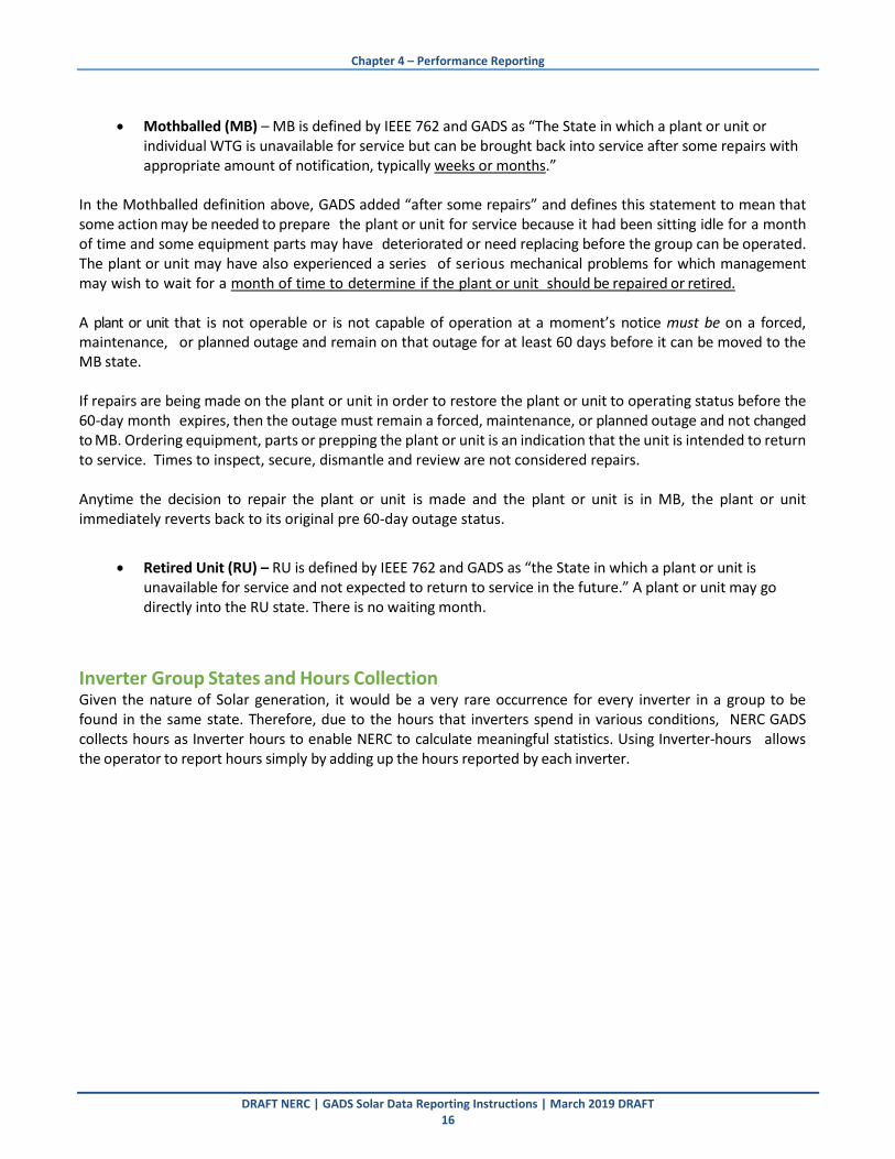
Mothballed (MB) – MB is defined by IEEE 762 and GADS as “The State in which a plant or unit or individual WTG is unavailable for service but can be brought back into service after some repairs with appropriate amount of notification, typically weeks or months.”
In the Mothballed definition above, GADS added “after some repairs” and defines this statement to mean that some action may be needed to prepare the plant or unit for service because it had been sitting idle for a month of time and some equipment parts may have deteriorated or need replacing before the group can be operated. The plant or unit may have also experienced a series of serious mechanical problems for which management may wish to wait for a month of time to determine if the plant or unit should be repaired or retired.
A plant or unit that is not operable or is not capable of operation at a moment’s notice must be on a forced, maintenance, or planned outage and remain on that outage for at least 60 days before it can be moved to the MB state. If repairs are being made on the plant or unit in order to restore the plant or unit to operating status before the 60‐day month expires, then the outage must remain a forced, maintenance, or planned outage and not changed to MB. Ordering equipment, parts or prepping the plant or unit is an indication that the unit is intended to return to service. Times to inspect, secure, dismantle and review are not considered repairs. Anytime the decision to repair the plant or unit is made and the plant or unit is in MB, the plant or unit immediately reverts back to its original pre 60-day outage status.
Retired Unit (RU) – RU is defined by IEEE 762 and GADS as “the State in which a plant or unit is unavailable for service and not expected to return to service in the future.” A plant or unit may go directly into the RU state. There is no waiting month.
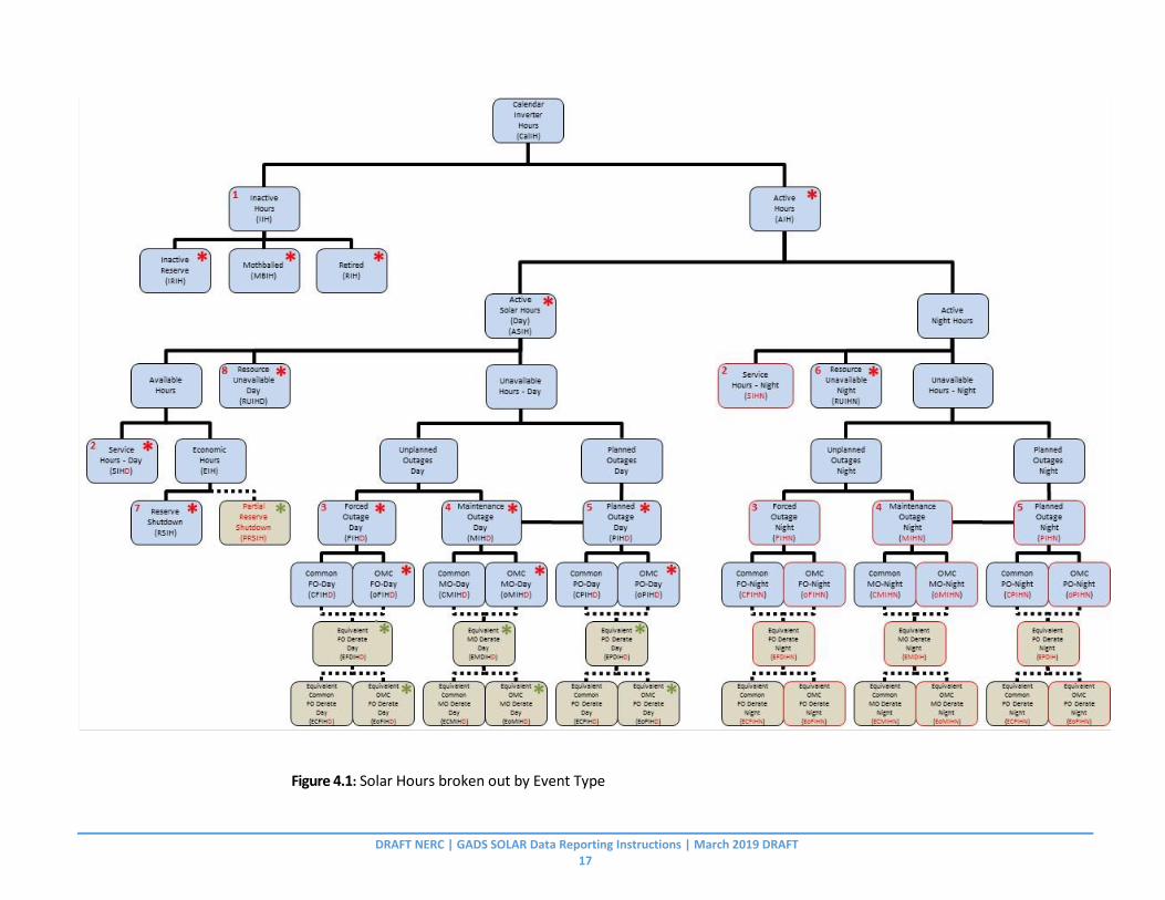
Inverter Group States and Hours Collection Given the nature of Solar generation, it would be a very rare occurrence for every inverter in a group to be found in the same state. Therefore, due to the hours that inverters spend in various conditions, NERC GADS collects hours as Inverter hours to enable NERC to calculate meaningful statistics. Using Inverter‐hours allows the operator to report hours simply by adding up the hours reported by each inverter.
DRAFT NERC | GADS SOLAR Data Reporting Instructions | March 2019 DRAFT 17
Figure 4.1: Solar Hours broken out by Event Type

DRAFT NERC | GADS SOLAR Data Reporting Instructions | March 2019 DRAFT 18
Service Inverter Hours (SIH) Service Inverter Hours are equal to the number of inverters in the group times the number of Calendar Hours in the month. SIH for any given condition for a given group is equal to the total number of Calendar Hours that each inverter in the group spent in the given condition.
All of the following time/condition classifications are considered to be in Service inverter‐hours. For example, the number of SIH for a group of 12 inverters in January (with 744 hours in January) would be 12 x 744 or 8,928 TH. If one of those inverters were mothballed, the Active Inverter Hours (AIH) would be 11 x 744 or 8,184 ACTH with 744 Inactive Inverter‐Hours. (reported as Mothballed Inverter Hours - MBIH)
Active Inverter hours (AIH) Active Inverter Hours (AIH) is the number of Inverter‐Hours being reported that the sub‐group is in the active state. AIH can vary in output reports (month, year, etc.) but for GADS reporting purposes, data is collected on the number of Inverter‐ Hours in a month. AIH was previously known as Month Inverter Hours.
In two instances, the AIH may be smaller than the normal month hours for the given month:
• When the sub‐group becomes commercially active, or
• When one or more inverters go into the Inactive Reserve, Mothballed, or Retired State.
The sum of Available Inverter‐Hours and Unavailable Inverter‐Hours must equal sub‐group Active Inverter‐Hours. If a group is commissioned after the first of the month, the group reporting obligation begins with the first full calendar month after the group was commissioned.
Inactive Inverter hours (IIH) (calculated) IIH is the number of inverter‐hours in a month being reported that the group is in the inactive state. Inactive States are reported under Inactive Reserve Inverter Hours (IRIH), Mothballed Inverter Hours (MBIH), and Retired Inverter Hours (RIH).
Active Solar Inverter Hours (ASIH) Active Solar Inverter Hours are equal to the number of inverters in the group times the number of Active Hours during Daylight in the month. Daylight Hours are defined as from the time between sunrise and sunset that produce energy in the inverter.
Reserve Shutdown Inverter hours (RSIH) RSIH is the sum of all inverter‐hours that the group is not available to the system for economic reasons. Do not include RSIH with the same equations with SIH (this would result in double counting total inverter‐hours). IEEE 762 and the NERC GADS DRI for Thermal/Hydro generators define RSIH as an inverter shutdown due to economic reasons. Economic is defined as negative energy pricing or lack of demand. To qualify the following must be true:
1. The inverter must be in an active state.

Chapter 4 – Performance Reporting
DRAFT NERC | GADS Solar Data Reporting Instructions | March 2019 DRAFT 19
2. The inverter must be available not in an outage state.
3. The inverter must not be in eminent danger of failure.
Note: Disabling an inverter (such as removing a processor card) immediately puts the inverter in an outage state and makes it no longer available.
Reserve Shutdown (RS) Economic for purposes, Reserve Shutdown is defined as negative energy pricing, lack of demand or market curtailments. It does not apply to financial decisions required to run the plant.
Partial Reserve Shutdown Economic for purposes, Partial Reserve Shutdown is defined as a time when full production is not needed and only a part of the energy that the system is capable of producing is delivered to the grid. These Partial Reserve Shutdown Inverter Hours are included in the Service Hours. Reported as Equivalent Partial Reserve shutdown Inverter Hours. Include examples in Appendix G.
Resource Unavailable Inverter-Hours Night (RUIHN) RUIHN is the number of inverter‐hours the group is not producing electricity due to the sun being below the horizon or too low to produce startup voltage. This includes normal system startup, calibrations, system checks and ramp-up, such as cable untwisting, battery checks, etc. RUIHN is classified as Available Inverter‐Hours for equipment calculations and Unavailable Inverter‐Hours for site calculations. See Figures D‐2, D3 and D‐4 later in this chapter.
Resource Unavailable Inverter hours Day (RUIHN) RUIHD is the number of inverter‐hours the group is not producing electricity during daylight hours but sunlight levels being too low to produce startup voltage. This includes normal system startup, calibrations, system checks and ramp-up, such as cable untwisting, battery checks, etc. RUIHN is classified as Available Inverter‐Hours for equipment calculations and Unavailable Inverter‐Hours for site calculations. See Figures D‐2, D3 and D‐4 later in this chapter.
Forced Outage Inverter hours (FOIH) – Performance and Equipment Outage Reporting FIH is the sum of all inverter‐hours that the group is off‐line due to forced events. FIH are all forced events where the group must be removed from service for repairs before the next Sunday at 23:59 (just before Sunday becomes Monday). Examples can be found in Appendix I.
OMC Forced Outage Inverter hours (oFOIH) oFIH is a subset of FIH that equals any forced inverter‐hours that were due to causes deemed to be outside of management control. For more information on OMC, refer to Appendix H. Examples can be found in Appendix I. Note that oFIH is a subset of FIH
Maintenance Inverter hours (MIH) – Performance and Equipment Outage Reporting MIH is the sum of all inverter‐hours that the sub‐group is off‐line due to a Maintenance Event.
A maintenance event is an event that can be deferred beyond the end of the next weekend (Sunday at 2400), but requires that an inverter be removed from service, another outage state, or Reserve Shutdown state before the next Planned event. Characteristically, a maintenance event can occur at any time during the year, has a flexible start date, may or may not have a predetermined duration, and is usually much shorter than a Planned Event.

Chapter 4 – Performance Reporting
DRAFT NERC | GADS Solar Data Reporting Instructions | March 2019 DRAFT 20
If an event occurs before Friday at 2400, the above definition applies. If the event occurs after Friday at 2400 and before Sunday at 2400, the Maintenance event will only apply if the event can be delayed past the next weekend, not the current one. If the event cannot be deferred, it is a Forced Event. Examples can be found in Appendix I.
OMC Maintenance Inverter hours (oMIH) oMIH is a sub‐set of MIH that equals any maintenance Inverter‐Hours that were due to causes deemed to be outside of management control (OMC). For more information on OMC, refer to Appendix H. Examples can be found in Appendix I. Note that oMIH is a subset of MIH
Planned Inverter hours (PIH) – Performance and Equipment Outage Reporting PIH is the sum of all Inverter‐Hours that the sub‐group is off‐line due to a planned event. A Planned Event is scheduled well in advance and is of predetermined duration and can occur several times a year. Examples can be found in Appendix I.
OMC Planned Inverter hours (oPIH) oPIH is a sub‐set of PIH that equals any planned Inverter‐Hours that were due to causes deemed to be outside of management control. For more information on OMC, refer to Appendix H. Note that oPIH is a subset of PIH
Site Available Inverter hours (SAIH) (Calculated) SAIH is the Active Inverter‐Hours (AIH) minus the sum of Resource Unavailable Inverter‐Hours Night (RUIHN) and Resource Unavailable Inverter Hours Day.
Equipment Available Inverter hours (EAIH) (Calculated) EAIH is the sum of the Service Inverter‐Hours (CIH), Resource Unavailable Inverter‐Hours Night (RUIHN) and Resource Unavailable Inverter‐Hours Day (RUIHD) – Equivalent Reserve Shutdown Inverter Hours (RSIH).
Site Unavailable Inverter hours (SUIH) (Calculated) SUIH is the sum of Planned Inverter‐Hours (PIH), Forced Inverter‐Hours (FIH), Maintenance Inverter‐ Hours (MIH) Resource Unavailable Inverter‐Hours Day (RUIHD) and Resource Unavailable Inverter‐Hours Night (RUIHN).
Equipment Unavailable Inverter hours (EUIH) (Calculated) EUIH is the sum of Planned Inverter Hours (PIH), Forced Inverter Hours (FIH), and Maintenance Inverter Hours (MIH). Equivalent Hours Equivalent hours occur when inverter power is reduced from the Maximum Inverter Capacity MW. The equivalent hours can be calculated several ways:
1. An individual inverter’s power is reduced. Example – a 1.5MW inverter is limited to 1.0MW of 10 hrs. This is a 33.3% reduction in power, so the equivalent outage hours are 10/3 – 3.33hrs.
2. A group of inverters maybe limited in their output. Example – a 100MW plant is limited to 50MW. This is a 50% restriction so 50% of the hours during the month are equivalent outage hours. 10 inverters for 8 hours = 80 hours total times 50% equals 40 equivalent outage hours.
3. Energy loss due to derate divided by expected generation times the Active Hours. Example – An inverter had a derate loss of 5MWH over 6Hrs. Expected generation was 15MWH. 5MWH / 15MWH x 6Hrs = 2 Equivalent Hours.
Note: Equivalent hours are only used in the numerator of equations (except ERSDIH) as the hours are already counted as contactor hours in the denominator. Inverter output is reduced but the unit is still on line or
Chapter 4 – Performance Reporting
DRAFT NERC | GADS Solar Data Reporting Instructions | March 2019 DRAFT 21
available.
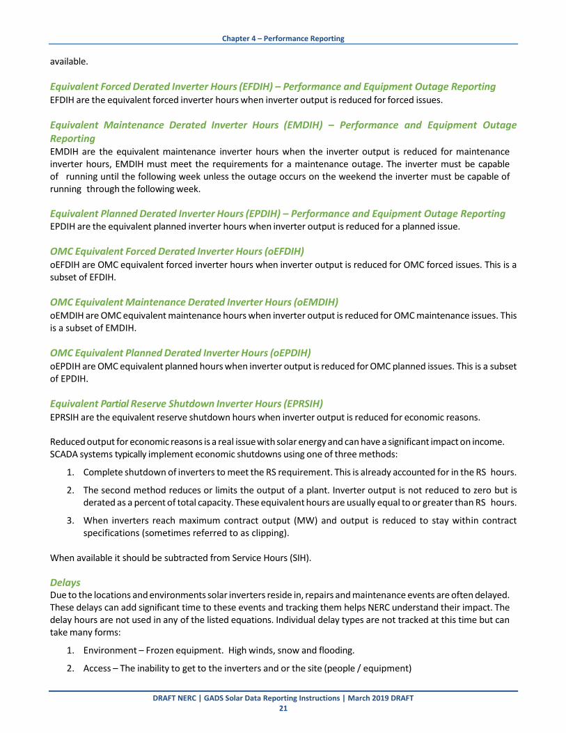
Equivalent Forced Derated Inverter Hours (EFDIH) – Performance and Equipment Outage Reporting EFDIH are the equivalent forced inverter hours when inverter output is reduced for forced issues.
Equivalent Maintenance Derated Inverter Hours (EMDIH) – Performance and Equipment Outage Reporting EMDIH are the equivalent maintenance inverter hours when the inverter output is reduced for maintenance inverter hours, EMDIH must meet the requirements for a maintenance outage. The inverter must be capable of running until the following week unless the outage occurs on the weekend the inverter must be capable of running through the following week.
Equivalent Planned Derated Inverter Hours (EPDIH) – Performance and Equipment Outage Reporting EPDIH are the equivalent planned inverter hours when inverter output is reduced for a planned issue.
OMC Equivalent Forced Derated Inverter Hours (oEFDIH) oEFDIH are OMC equivalent forced inverter hours when inverter output is reduced for OMC forced issues. This is a subset of EFDIH.
OMC Equivalent Maintenance Derated Inverter Hours (oEMDIH) oEMDIH are OMC equivalent maintenance hours when inverter output is reduced for OMC maintenance issues. This is a subset of EMDIH.
OMC Equivalent Planned Derated Inverter Hours (oEPDIH) oEPDIH are OMC equivalent planned hours when inverter output is reduced for OMC planned issues. This is a subset of EPDIH.
Equivalent Partial Reserve Shutdown Inverter Hours (EPRSIH) EPRSIH are the equivalent reserve shutdown hours when inverter output is reduced for economic reasons.
Reduced output for economic reasons is a real issue with solar energy and can have a significant impact on income. SCADA systems typically implement economic shutdowns using one of three methods:
1. Complete shutdown of inverters to meet the RS requirement. This is already accounted for in the RS hours.
2. The second method reduces or limits the output of a plant. Inverter output is not reduced to zero but is derated as a percent of total capacity. These equivalent hours are usually equal to or greater than RS hours.
3. When inverters reach maximum contract output (MW) and output is reduced to stay within contract specifications (sometimes referred to as clipping).
When available it should be subtracted from Service Hours (SIH). Delays Due to the locations and environments solar inverters reside in, repairs and maintenance events are often delayed. These delays can add significant time to these events and tracking them helps NERC understand their impact. The delay hours are not used in any of the listed equations. Individual delay types are not tracked at this time but can take many forms:
1. Environment – Frozen equipment. High winds, snow and flooding.
2. Access – The inability to get to the inverters and or the site (people / equipment)
Chapter 4 – Performance Reporting
DRAFT NERC | GADS Solar Data Reporting Instructions | March 2019 DRAFT 22
3. Equipment – Availability and or permitting.
4. Labor – Limited availability of labor or inadequate labor.
5. Material – High failure rates deplete inventory resulting in long lead times for repairs or parts availability. Force Delay Inverter Hours (FXDIH) – Performance and Equipment Outage Reporting FXDIH are the delay hours that extend repairs beyond their expected repair month.
Maintenance Delay Inverter Hours (MXDIH) – Performance and Equipment Outage Reporting MXDIH are the delay hours that extend repairs beyond their expected maintenance month.
Planned Delay Inverter Hours (PXDIH) – Performance and Equipment Outage Reporting PXDIH are the delay hours that extend repairs beyond their expected planned month.
Priority of Outage Reporting In some instances, there may be more than one event starting at the same time. When events start at the same time, the below list identifies how to select the correct outage type. Once an outage begins, outage types are not changed until the current outage is finished.
1. Service Inverter‐Hours
2. Forced Inverter‐Hours
3. Maintenance
4. Resource Unavailable Inverter Hours Day

Chapter 4 – Performance Reporting
DRAFT NERC | GADS Solar Data Reporting Instructions | March 2019 DRAFT 23
Figure 4.2 IEC, IEEE, NERC GADS Cross Reference

DRAFT NERC | GADS SOLAR Data Reporting Instructions | March 2019 DRAFT 24
Inverter Group Performance Data Layout (Excel or CSV Format)
Table 4.1: Inverter Group Performance Data Layout
Column Field Name Column Header Label
Entry Type Mandatory or Voluntary
1 Entity ID EntityID Alpha-Numeric-10 Mandatory
2 Plant ID PlantIDName Alpha‐Numeric ‐ 45 Mandatory
3 Inverter Group ID GroupIDName Alpha‐Numeric ‐ 45 Mandatory 4 Report Period (month) ReptMonth Numeric ‐ 2 Mandatory
5 Report Year ReptYear Numeric ‐ 4 Mandatory
6 Inverter Group Availability Status InvAvailStatus Alpha‐Numeric ‐ 2 Mandatory
7 Gross Actual Generation (GAG) (MWh) GAG Numeric ‐ 10 Mandatory
8 Net Actual Generation (NAG) (MWh) NAG Numeric ‐ 10 Mandatory
9 Net Maximum Capacity (NMC) (MW) NMC Numeric ‐ 5 + 3 decimals Mandatory
10 Monthly Plane of Array (kwh/m^2) MPOA Numeric ‐ 3 + 3 decimals Mandatory
11 Performance Ratio PerfRatio Numeric ‐ 1 + 3 decimals Mandatory
12 Expected Generation (MWh) EG Numeric ‐ 10 Mandatory
13 Active Solar Inverter Hours ASIH Numeric ‐ 7 + 2 decimals Mandatory
14 Active Inverter Hours AIH Numeric ‐ 7 + 2 decimals Mandatory
15 Inactive Reserve Inverter Hours IRIH Numeric ‐ 7 + 2 decimals Mandatory
16 Mothballed Inverter Hours MBIH Numeric ‐ 7 + 2 decimals Mandatory
17 Retired Unit Inverter Hours RIH Numeric ‐ 7 + 2 decimals Mandatory
18 Service Inverter Hours Day SIHD Numeric ‐ 7 + 2 decimals Mandatory
19 Reserve Shutdown Inverter Hours RSIH Numeric ‐ 7 + 2 decimals Mandatory
20 Equivalent Partial Reserve Shutdown Inverter Hours
EPRSIH Numeric ‐ 7 + 2 decimals Mandatory
21 Forced Outage Inverter Hours Day FOIHD Numeric ‐ 7 + 2 decimals Mandatory
22 Maintenance Inverter Hours Day MIHD Numeric ‐ 7 + 2 decimals Mandatory
23 Planned Inverter Hours Day PIHD Numeric ‐ 7 + 2 decimals Mandatory
24 OMC Forced Outage Inverter Hours Day OFOIHD Numeric ‐ 7 + 2 decimals Mandatory
25 OMC Maintenance Inverter Hours Day OMIHD Numeric ‐ 7 + 2 decimals Mandatory
26 OMC Planned Inverter Hours Day OPIHD Numeric ‐ 7 + 2 decimals Mandatory
27 Resource Unavailable Inverter Hours - Day
RUIHD Numeric ‐ 7 + 2 decimals Mandatory
28 Equivalent Partial Resource Unavailable Inverter Hours - Day
EPRUIHD Numeric ‐ 7 + 2 decimals Mandatory
29 Equivalent Forced Derate Inverter Hours Day
EFDIHD Numeric ‐ 7 + 2 decimals Mandatory
30 Equivalent Maintenance Derate Inverter Hours Day
EMDIHD Numeric ‐ 7 + 2 decimals Mandatory
31 Equivalent Planned Derate Hours Day EPDIHD Numeric ‐ 7 + 2 decimals Mandatory

25
Table 4.1: Inverter Group Performance Data Layout
32 OMC Equivalent Forced Derated Inverter Hours Day
OEFDIHD Numeric ‐ 7 + 2 decimals Mandatory
33 OMC Equivalent Maintenance Derated Inverter Hours Day
OEMDIHD Numeric ‐ 7 + 2 decimals Mandatory
34 OMC Equivalent Planned Derated Inverter Hours Day
OEPDIHD Numeric ‐ 7 + 2 decimals Mandatory
35 Forced Delay Inverter Hours Day FDIHD Numeric ‐ 7 + 2 decimals Mandatory
36 Maintenance Delay Inverter Hours Day MDIHD Numeric ‐ 7 + 2 decimals Mandatory
37 Planned Delay Inverter Hours Day PDIHD Numeric ‐ 7 + 2 decimals Mandatory
38 Service Inverter Hours Night SIHN Numeric ‐ 7 + 2 decimals Mandatory
39 Forced Outage Inverter Hours Night FOIHN Numeric ‐ 7 + 2 decimals Mandatory
40 Maintenance Inverter Hours Night MIHN Numeric ‐ 7 + 2 decimals Mandatory
41 Planned Inverter Hours Night PIHN Numeric ‐ 7 + 2 decimals Mandatory 42 OMC Forced Outage Inverter Hours Night OFOIHN Numeric ‐ 7 + 2 decimals Mandatory
43 OMC Maintenance Inverter Hours Night OMIHN Numeric ‐ 7 + 2 decimals Mandatory
44 OMC Planned Inverter Hours Night OPIHN Numeric ‐ 7 + 2 decimals Mandatory
45 Resource Unavailable Inverter Hours - Night
RUIHN Numeric ‐ 7 + 2 decimals Mandatory
46 Equivalent Forced Derated Inverter Hours Night
EFDIHN Numeric ‐ 7 + 2 decimals Mandatory
47 Equivalent Maintenance Derated Inverter Hours Night
EMDIHN Numeric ‐ 7 + 2 decimals Mandatory
48 Equivalent Planned Derated Hours Night EPDIHN Numeric ‐ 7 + 2 decimals Mandatory
49 OMC Equivalent Forced Derated Inverter Hours Night
OEFDIHN Numeric ‐ 7 + 2 decimals Mandatory
50 OMC Equivalent Maintenance Derated Inverter Hours Night
OEMDIHN Numeric ‐ 7 + 2 decimals Mandatory
51 OMC Equivalent Planned Derated Inverter Hours Night
OEPDIHN Numeric ‐ 7 + 2 decimals Mandatory
52 Forced Delay Inverter Hours Night FDIHN Numeric ‐ 7 + 2 decimals Mandatory
53 Maintenance Delay Inverter Hours Night MDIHN Numeric ‐ 7 + 2 decimals Mandatory 54 Planned Delay Inverter Hours Night PDIHN Numeric ‐ 7 + 2 decimals Mandatory
Table 4.2: Inverter Group Performance Data Descriptions
Column Field Name Description
1 Entity ID
Enter the NERC Compliance Registry ID number (NCR ID) or voluntary reporting ID assigned by NERC of the organization that operates the Solar plant.

26
Table 4.2: Inverter Group Performance Data Descriptions
2 Plant ID Enter the Plant ID assigned by the GADS Solar application. This is assigned in the Plant Configuration.
3 Inverter Group ID Enter the Inverter Group ID assigned by the GADS Solar application.
4 Report Period (month) Enter the two‐digit month (MM) for which the performance data is being reported. See Appendix F Table 13.
5 Report Year
Enter the four‐digit year (YYYY) for which the performance data is being reported.
6
Inverter Group Availability Status
Select the status of the entire group during the being reported. See Appendix F Table 14
7 Gross Actual Generation (GAG) (MWh)
Enter the total energy generated at the Inverter Group level (MWh). This is the sum of the AC inverter outputs for the group.
8 Net Actual Generation (NAG) (MWh)
Enter the net generation (MWh) recorded at the inverter boundary (usually the revenue meter).
It is possible to have a negative net actual generation value if the group’s station service or auxiliary loads are greater than total generation.
9 Net Maximum Capacity (NMC) (MW)
Enter the Maximum AC generating capability at the inverter boundary.
This is equal to the installed capacity less any electrical losses such as transformation losses, line losses, and other losses due to transmission between the inverter and the revenue meter. .
10 Monthly Plane of Array (Mwh/m^2) (MPOA)
Enter the Monthly Plane of Array (MWh/m^2) value.
11 Performance Ratio
Enter the Performance Ratio for the month.
This is calculated on DC Capacity (DC Nameplate rating) power capability and actual AC power delivered from the inverter. Along with adjustments for measured Plane of Array Irradiance, power degradation, Inverter efficiency, and module temperature corrections. 6
12 Expected Generation (MWh)
Enter the expected generation (MWh) expected at the inverter group boundary
This is based on solar-day hours7 and daily energy produced per hour, summed up for the month.
6 Performance Ratio is based on the NREL Weather Corrected Performance ratio and IEC 61724 [1]. While the NREL paper recommends Flash Point Data for DC Capacity, the DC Nameplate Rating is more commonly known. 7 See Glossary for definition of solar-day hours.

27
Table 4.2: Inverter Group Performance Data Descriptions
13 Active Solar Inverter Hours (Day) (ASIH)
Enter the number ofnumber of inverter hours (number of inverters times number of hours) from Sunrise to Sunset during the month being reported. 8 This sum is across all inverters in the Inverter Group
14 Active Inverter Hours (AIH)
Enter the number of inverter hours (number of inverters times number of hours) that the inverter group is in the active state. AIH for GADS Solar reporting purposes refers to the number of inverter hours during the month being reported.
15 Inactive Reserve Inverter Hours (IRIH)
Total number of inverter hours (number of inverters times number of hours) that the inverter group is in the inactive reserve state during the month being reported. (Inactive)
16 Mothballed Inverter Hours (MBIH)
Total number of inverter hours (number of inverters times number of hours) that the inverter group is in the mothballed state during the month being reported. (Inactive)
17 Retired Unit Inverter Hours (RIH)
Total number of inverter hours (number of inverters times number of hours) that the inverter group is in a permanently retired state during the month being reported. (Inactive)
18 Service Inverter Hours Day (SIHD)
Enter the number of inverter hours (number of inverters times number of hours) the inverter group is synchronized to the grid (in service) during daytime hours for the month being reported.
It is the total number of inverter hours that inverter is synchronized to the grid and producing positive power during daytime hours for the month being reported. 19
Reserve Shutdown Inverter Hours (RSIH)
Enter the number of inverter hours (number of inverters times number of hours) the inverter group is off‐line for economic reasons but available for service during daytime hours for the month being reported.
If the inverter group is not available due to an outage condition, it is not a reserve shutdown.
20
Equivalent Partial Reserve Shutdown Inverter Hours (EPRSIH)
The sum of Equivalent Inverter Hours imposed by Reserve Shutdown limited output demands for economic reasons during daytime hours for the month being reported.
21 Forced Outage Inverter Hours Day (FOIHD)
Enter the number of inverter hours (number of inverters times number of hours) that the inverter group is off‐line due to forced events during daytime hours for the month being reported.
FIH are all forced events where the Inverter group must be removed from service for repairs before the next Sunday at 23:59 (just before Sunday becomes Monday).
Note: FOIHD includes OMC Forced Inverter Hours (oFOIHD)
8 Sunrise and sunset as defined for plant location by the National Oceanic and Atmospheric Administration: www.noaa.gov

28
Table 4.2: Inverter Group Performance Data Descriptions
22 Maintenance Inverter Hours Day (MIHD)
Enter the number of inverter hours (number of inverters times number of hours) that the inverter group is off‐line due to a maintenance event during daytime hours for the month being reported.
The inverter group must be capable of running until the following week unless the outage occurs on the weekend the inverter must be capable of running through the following week.
Note: MIHD includes OMC Maintenance Inverter‐Hours (oMIHD)
23 Planned Inverter Hours Day (PIHD)
Enter the number of inverter hours (number of inverters times number of hours) that the inverter group is off‐line due to a planned event during daytime hours for the month being reported.
A PIH event is scheduled well in advance and is of a predetermined duration and can occur several times a year.
Note: PIHD includes OMC Planned Inverter‐Hours (oPIHD)
24 OMC Forced Outage Inverter Hours Day (OFOIHD)
Subset of FOIH, OMC hours are hours that the group is off‐line due to events that are outside management control, such as abnormal weather or off‐taker planned or unplanned downtime during daytime hours for the month being reported.
See Appendix H for further details.
25 OMC Maintenance Inverter Hours Day (OMIHD)
Subset of MIH, accounting for Maintenance Inverter Hours that are due to events deemed to be outside of management control during daytime hours for the month being reported.
26 OMC Planned Inverter Hours Day (OPIHD)
Subset of PIH, accounting for Planned Inverter Hours that are due to events deemed to be outside of management control during daytime hours for the month being reported.
27 Resource Unavailable Inverter Hours – Day (RUIHD)
The number of inverter hours (number of inverters times number of hours) that the inverters are available but not producing electricity for environmental conditions that are outside the operating specifications of the Solar inverter during daytime hours for the month being reported (i.e., low / high Solar and includes normal systems checks and calibrations). The system is delivering no electricity.
28
Equivalent Partial Resource Unavailable Inverter Hours – Day (EPRUIHD)
The number of equivalent inverter hours that the inverters are available but not producing electricity for environmental conditions that are outside the operating specifications of the Solar inverter during daytime hours for the month being reported (i.e., low / high Solar and includes normal systems checks and calibrations). The system is still delivering electricity.
29 Equivalent Forced Derated Inverter Hours Day (EFDIHD)
Total number of equivalent forced hours during daytime hours for the month being reported.
EFDIHD includes oEFDIHD.
30
Equivalent Maintenance Derated Inverter Hours Day (EMDIHD)
Total number of equivalent maintenance hours during daytime hours for the month being reported.
EMDIHD includes oEMDIHD.
29
Table 4.2: Inverter Group Performance Data Descriptions
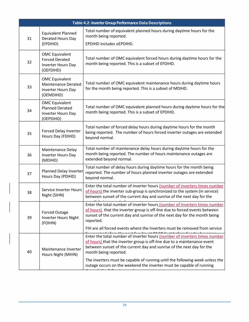
31 Equivalent Planned Derated Hours Day (EPDIHD)
Total number of equivalent planned hours during daytime hours for the month being reported.
EPDIHD includes oEPDIHD.
32
OMC Equivalent Forced Derated Inverter Hours Day (OEFDIHD)
Total number of OMC equivalent forced hours during daytime hours for the month being reported. This is a subset of EFDIHD.
33
OMC Equivalent Maintenance Derated Inverter Hours Day (OEMDIHD)
Total number of OMC equivalent maintenance hours during daytime hours for the month being reported. This is a subset of MDIHD.
34
OMC Equivalent Planned Derated Inverter Hours Day (OEPDIHD)
Total number of OMC equivalent planned hours during daytime hours for the month being reported. This is a subset of EPDIHD.
35 Forced Delay Inverter Hours Day (FDIHD)
Total number of forced delay hours during daytime hours for the month being reported. The number of hours forced inverter outages are extended beyond normal.
36 Maintenance Delay Inverter Hours Day (MDIHD)
Total number of maintenance delay hours during daytime hours for the month being reported. The number of hours maintenance outages are extended beyond normal.
37 Planned Delay Inverter Hours Day (PDIHD)
Total number of delay hours during daytime hours for the month being reported. The number of hours planned inverter outages are extended beyond normal.
38 Service Inverter Hours Night (SIHN)
Enter the total number of inverter hours (number of inverters times number of hours) the inverter sub‐group is synchronized to the system (in service) between sunset of the current day and sunrise of the next day for the month being reported.
It is the inverter hours that the main breaker is closed, and generation is provided to the grid.
39 Forced Outage Inverter Hours Night (FOIHN)
Enter the total number of inverter hours (number of inverters times number of hours) that the inverter group is off‐line due to forced events between sunset of the current day and sunrise of the next day for the month being reported.
FIH are all forced events where the Inverters must be removed from service for repairs before the next Sunday at 23:59 (just before Sunday becomes Monday).
Note: FOIHN includes OMC Forced Inverter‐Hours (oFOIHN) 40
Maintenance Inverter Hours Night (MIHN)
Enter the total number of inverter hours (number of inverters times number of hours) that the inverter group is off‐line due to a maintenance event between sunset of the current day and sunrise of the next day for the month being reported.
The inverters must be capable of running until the following week unless the outage occurs on the weekend the inverter must be capable of running through the following week.
Note: MIHN includes OMC Maintenance Inverter Hours (oMIHN)

30
Table 4.2: Inverter Group Performance Data Descriptions
41 Planned Inverter Hours Night (PIHN)
Enter the number of inverter hours (number of inverters times number of hours) that the inverter group is off‐line due to a planned event between sunset of the current day and sunrise of the next day for the month being reported.
A PIHN event is scheduled well in advance and is of a predetermined duration and can occur several times a year.
Note: PIHN includes OMC Planned Inverter Hours (oPIHN)
42 OMC Forced Outage Inverter Hours Night (OFOIHN)
Enter the number of inverter hours (number of inverters times number of hours) that the group is off‐line due to events that are outside management control, such as abnormal weather or off‐taker planned or unplanned downtime between sunset of the current day and sunrise of the next day for the month being reported.
See Appendix H for further details.
43 OMC Maintenance Inverter Hours Night (OMIHN)
Subset of MIHN, accounting for Maintenance Inverter Hours that are due to events deemed to be outside of management control between sunset of the current day and sunrise of the next day for the month being reported.
44 OMC Planned Inverter Hours Night (OPIHN)
Subset of PIHN, accounting for Planned Inverter Hours that are due to events deemed to be outside of management control between sunset of the current day and sunrise of the next day for the month being reported.
45 Resource Unavailable Inverter Hours – Night (RUIHN)
The total number of Inverter hours (number of inverters times number of hours) between sunset of the current day and sunrise of the next day for the month being reported that the inverters are available but not producing electricity for environmental conditions that are outside the operating specifications of the Solar inverter.
46 Equivalent Forced Derated Inverter Hours Night (EFDIHN)
Total number of equivalent forced inverter hours between sunset of the current day and sunrise of the next day for the month being reported.
EFDIHN includes oEFDIHN.
47
Equivalent Maintenance Derated Inverter Hours Night (EMDIHN)
Total number of equivalent maintenance hours between sunset of the current day and sunrise of the next day for the month being reported.
EMDTIN includes oEMDIHN.
48 Equivalent Planned Derated Hours Night (EPDIHN)
Total number of equivalent planned hours between sunset of the current day and sunrise of the next day for the month being reported.
EPDIHN includes oEPDIHN.
49
OMC Equivalent Forced Derated Inverter Hours Night (OEFDIHN)
Total number of OMC equivalent forced hours between sunset of the current day and sunrise of the next day for the month being reported.

31
Table 4.2: Inverter Group Performance Data Descriptions
50
OMC Equivalent Maintenance Derated Inverter Hours Night (OEMDIHN)
Total number of OMC equivalent maintenance hours between sunset of the current day and sunrise of the next day for the month being reported.
51
OMC Equivalent Planned Derated Inverter Hours Night (OEPDIHN)
Total number of OMC equivalent planned hours between sunset of the current day and sunrise of the next day for the month being reported.
52 Forced Delay Inverter Hours Night (FDIHN)
Total number of forced delay hours between sunset of the current day and sunrise of the next day for the month being reported. The number of hours forced inverter outages are extended beyond normal.
53 Maintenance Delay Inverter Hours Night (MDIHN)
Total number of maintenance delay hours between sunset of the current day and sunrise of the next day for the month being reported. The number of hours maintenance outages are extended beyond normal.
54 Planned Delay Inverter Hours Night (PDIHN)
Total number of delay hours between sunset of the current day and sunrise of the next day for the month being reported. The number of hours planned inverter outages are extended beyond normal.
Energy Storage Performance Data Layout
Inverter Group performance data provides information pertaining to Inverter Group operations during a month. Performance data are required for all energy storage groups.
Performance Storage Data Layout (Excel or CSV Format)
Table 4.3: Energy Storage Performance Data Layout
Column Field Name Column Header Label
Entry Type Mandatory or Voluntary
1 Entity ID EntityID Alpha-Numeric-10 Mandatory
2 Plant ID PlantIDName Alpha‐Numeric ‐ 45 Mandatory
3 Energy Storage Group ID GroupIDName Alpha‐Numeric ‐ 45 Mandatory 4 Report Period (month) ReptMonth Numeric ‐ 2 Mandatory
5 Report Year ReptYear Numeric ‐ 4 Mandatory
6 Storage Group Availability Status SGAvailStatus Alpha‐Numeric ‐ 2 Mandatory 7 Charge Generation (MWh) ChgMWh Numeric ‐ 10 Mandatory
8 Discharge Generation (MWh) DischgMWh Numeric ‐ 10 Mandatory
9 Charging Hours ChgHrs Numeric ‐ 3 + 2 decimals Mandatory
10 Discharging Hours DisChgHrs Numeric ‐ 3 + 2 decimals Mandatory
11 Forced Outage Hours StorageFOH Numeric ‐ 3 + 2 decimals Mandatory
12 Maintenance Outage Hours StorageMOH Numeric ‐ 3 + 2 decimals Mandatory
13 Planned Outage Hours StoragePOH Numeric ‐ 3 + 2 decimals Mandatory

32
Table 4.3: Energy Storage Performance Data Layout
14 OMC Forced Outage Hours StorageOFOH Numeric ‐ 3 + 2 decimals Voluntary
15 OMC Maintenance Outage Hours StorageOMOH Numeric ‐ 3 + 2 decimals Voluntary
16 OMC Planned Outage Hours StorageOPOH Numeric ‐ 3 + 2 decimals Voluntary
Table 4.4: Energy Storage Performance Data Descriptions
Column Field Name Description
1 Entity ID
Enter the NERC Compliance Registry ID number (NCR ID) or voluntary reporting ID assigned by NERC of the organization that operates the Solar plant.
2 Plant ID Enter the Plant ID assigned by the GADS Solar application. This is assigned in the Plant Configuration.
3 Energy Storage Group ID
Enter the Energy Storage Group ID assigned by the GADS Solar application.
4 Report Month (month) Enter the two‐digit month (MM) for which the performance data is being reported. See Appendix F Table 13.
5 Report Year
Enter the four‐digit year (YYYY) for which the performance data is being reported.
6
Storage Availability Status
Select the status of the entire group for the month being reported. See Appendix F Table 14.
7 Charge Generation (MWh)
Enter the MWh of charge to the Energy Storage Group for the month being reported.
8 Discharge Generation (MWh)
Enter the MWh of discharge from the Energy Storage Group for the month being reported.
9 Charging Hours Enter the number of charging hours to the Energy Storage Group for the month being reported.
10 Discharging Hours Enter the number of discharge hours from the Energy Storage Group for the month being reported.
11 Forced Outage Hours Enter the number of hours that the Energy Storage Group is in a Forced Outage State.
12 Maintenance Outage Hours
Enter the number of hours that the Energy Storage Group is in a Maintenance Outage State
13 Planned Outage Hours Enter the number of hours that the Energy Storage Group is in a Planned Outage State.
14 OMC Forced Outage Hours
Enter the number of hours that the Energy Storage Group was in a Forced Outage State due to causes Outside Management Control. This is a subset of Forced Outage Hours.

33
Table 4.4: Energy Storage Performance Data Descriptions
15 OMC Maintenance Outage Hours
Enter the number of hours that the Energy Storage Group was in a Maintenance Outage State due to causes Outside Management Control. This is a subset of Maintenance Outage Hours.
16 OMC Planned Outage Hours
Enter the number of hours that the Energy Storage Group was in a Planned Outage State due to causes Outside Management Control. This is a subset of Planned Outage Hours.

34
Chapter 5 – Event Reporting
Event Detail Reporting
Event Detail reporting is used to identify outages or deratings that are potentially impactful to the grid. Outages that take place overnight (including Planned and Maintenance Outages) and are fixed overnight do not impact the grid. Outages that take place overnight but are not fixed until daytime are impactful to the grid. Events are reported at the Plant level. An event begins with an instantaneous loss of 20 MW or more of Net generating capacity/Cease Injection of Current during daytime hours. An event ends when 95% of the impacted inverters are returned to service.
o Applies at Plant level o E.g. 20 solar inverters trip off-line, the event ends when 19 of the solar inverters return
back to service. o Instantaneous loss - A loss is within 60 seconds during daytime hours
Solar-PV Event Definition Start and End Time
Start time of an event will begin when the loss of 20 MW or more of net actual capacity that occurs for at least 60 seconds in duration during daytime hours. The corresponding end time of an event will be recorded as the time when 95% of lost net actual capacity is recovered.
E.g. 20 solar inverters trip off-line, the event ends when 19 of the solar inverters return back to service.
OR
A second possible start time of an event occurs when a cessation of injection of current that occurs for at least 60 seconds during daytime time hours is experienced. The corresponding end time of the event will be recorded as the time when injection of current resumes. The current is not explicitly recorded, the event is measured as lost capacity in terms of power and in units of MW.
Applies at Plant level E.g. 20 solar inverters trip off-line, the event ends when 19 of the solar inverters return back to service. Instantaneous loss - A loss is within 60 seconds during daytime hours
Event Detail reporting is mandatory for all plants.
Plant Event Detail Data Layout (CSV Format)
Table 5.1: Plant Event Detail Data Layout
Column Field Name Column Header Label
Entry Type Mandatory or Voluntary
1 Entity ID EntityID Alpha-Numeric-10 Mandatory
2 Plant ID PlantID Alpha‐Numeric ‐ 45 Mandatory 3 Event ID EventID Alpha-Numeric-20 Mandatory
4 Time Zone TimeZone Alpha-3 Mandatory
5 Event Start Date/Time StartDT mm/dd/yyyy HH:MM Mandatory 6 Event End date/Time EndDT mm/dd/yyyy HH:MM Mandatory
7 Event Type EventType Alpha-Numeric-10 Mandatory
8 MW Output at time of Event MWOut Numeric ‐ 5 + 3 decimals Mandatory

35
Table 5.1: Plant Event Detail Data Layout
9 Lost MW Capacity MWLoss Numeric ‐ 5 + 3 decimals Mandatory
10 Cause Code CauseCode Numeric ‐ 5 Mandatory
11 Contributing Operating Condition Condition AlphaNumeric – 1 Mandatory
12 Description Description Alpha-Numeric-500 Voluntary
13 Potential MWH Production loss (Expected Generation lost)
GenLoss Numeric ‐ 10 Mandatory
14 Production supplied by Energy Storage MWh GenES Numberic – 10 Mandatory
15 Duration of Energy Storage Support ESDuration Numeric – 6 + 2 decimals Mandatory
Table 5.2: Plant Event Detail Data Descriptions
Column Field Name Description
1 Entity ID
Enter the NERC Compliance Registry ID number (NCR ID) or voluntary reporting ID assigned by NERC of the organization that operates the Solar plant.
2 Plant ID Enter the Plant ID assigned by the GADS Solar application. This is assigned in the Plant Configuration.
3 Event ID Enter a unique identification for the event
4 Time Zone Enter the Time Zone in which data are reported for the plant. This time zone will be used to convert Event Start and End Date/Times to UTC.
5 Event Start Date/Time Identify the time of the Event Start (when the site is completely unavailable/ or 20 MW loss for 5 minutes or more) (mm/dd/yyyy HH:MM) (24 hour clock used) 6 Event End Date/Time Identify the time of the end of the Event (This is when the cause of the event is over, and the site is available.) (mm/dd/yyyy HH:MM) (24 hour clock used)
7 Event Type Enter the type of Event (Forced, Maintenance, Planned)
8 MW Output at Time of Event
Enter the MW Output at the time of the Event start. (Net Actual Capacity)
9 Lost MW Capacity Enter the amount of MW Capacity lost due to the event. (Change in Net Actual Capacity)
10 Cause Code
Enter the cause for the outage. See Appendix C for a complete list of the cause codes and descriptions. Generally, this is the equipment that went out during the event. If equipment was pre-emptively shut down in preparation for a storm to protect the equipment, enter the storm cause code and Contributing Operating Condition. If a storm damaged equipment, enter the equipment damaged in the Cause Code and enter Storm in Contributing Operating Condition.
11 Contributing Operating Condition
Enter the underlying environment. See Appendix C for a complete list of Contributing Operating Condition. Such as Storm, Flood, Cold Weather.
12 Description Describe the Event in more detail to allow comparison to similar events.

36
Table 5.2: Plant Event Detail Data Descriptions
13 Potential MWH Production Loss
Enter the number of Potential MWH loss during the duration of the event. This should be based on Expected Generation. This is the expected Generation of the duration of the outage. See Appendix G for possible outage weightings.
14 Production supplied by Energy Storage
Enter the number of MWh of Generation that energy storage supplied during the event.
15 Duration of Energy Storage Support
Enter the hours and minutes of duration that Energy Storage was able to supply during the event. This should be less than or equal to the duration of the Event.
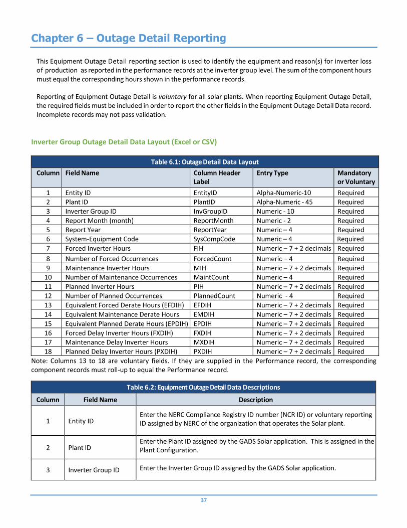
37
Chapter 6 – Outage Detail Reporting
This Equipment Outage Detail reporting section is used to identify the equipment and reason(s) for inverter loss of production as reported in the performance records at the inverter group level. The sum of the component hours must equal the corresponding hours shown in the performance records.
Reporting of Equipment Outage Detail is voluntary for all solar plants. When reporting Equipment Outage Detail, the required fields must be included in order to report the other fields in the Equipment Outage Detail Data record. Incomplete records may not pass validation.
Inverter Group Outage Detail Data Layout (Excel or CSV)
Table 6.1: Outage Detail Data Layout
Column Field Name Column Header Label
Entry Type Mandatory or Voluntary
1 Entity ID EntityID Alpha-Numeric-10 Required
2 Plant ID PlantID Alpha‐Numeric ‐ 45 Required
3 Inverter Group ID InvGroupID Numeric ‐ 10 Required
4 Report Month (month) ReportMonth Numeric - 2 Required
5 Report Year ReportYear Numeric – 4 Required 6 System-Equipment Code SysCompCode Numeric – 4 Required
7 Forced Inverter Hours FIH Numeric – 7 + 2 decimals Required
8 Number of Forced Occurrences ForcedCount Numeric – 4 Required
9 Maintenance Inverter Hours MIH Numeric – 7 + 2 decimals Required
10 Number of Maintenance Occurrences MaintCount Numeric – 4 Required
11 Planned Inverter Hours PIH Numeric – 7 + 2 decimals Required
12 Number of Planned Occurrences PlannedCount Numeric - 4 Required
13 Equivalent Forced Derate Hours (EFDIH) (Voluntary)
EFDIH Numeric – 7 + 2 decimals Required
14 Equivalent Maintenance Derate Hours (EMDIH) (Voluntary)
EMDIH Numeric – 7 + 2 decimals Required
15 Equivalent Planned Derate Hours (EPDIH) (Voluntary)
EPDIH Numeric – 7 + 2 decimals Required
16 Forced Delay Inverter Hours (FXDIH) (Voluntary)
FXDIH Numeric – 7 + 2 decimals Required
17 Maintenance Delay Inverter Hours (MXDIH) (Voluntary)
MXDIH Numeric – 7 + 2 decimals Required
18 Planned Delay Inverter Hours (PXDIH) (Voluntary)
PXDIH Numeric – 7 + 2 decimals Required
Note: Columns 13 to 18 are voluntary fields. If they are supplied in the Performance record, the corresponding component records must roll-up to equal the Performance record.
Table 6.2: Equipment Outage Detail Data Descriptions
Column Field Name Description
1 Entity ID Enter the NERC Compliance Registry ID number (NCR ID) or voluntary reporting ID assigned by NERC of the organization that operates the Solar plant.
2 Plant ID Enter the Plant ID assigned by the GADS Solar application. This is assigned in the Plant Configuration.
3 Inverter Group ID Enter the Inverter Group ID assigned by the GADS Solar application.

38
Table 6.2: Equipment Outage Detail Data Descriptions
4 Report Month (month)
Enter the two‐digit month (MM) for which the performance data is being reported. See Appendix F Table 13.
5 Report Year
Enter the four‐digit year (YYYY) for which the performance data is being reported.
6
System-Equipment Outage Detail Code
Enter the cause for the outage. See Appendix C for a complete list of the Equipment Outage Detail Codes and descriptions.
7 Forced Inverter Hours Enter the number of Forced Inverter Hours associated with the Equipment Outage Detail Code.
8 Number of Forced Occurrences
Enter the number of forced outages associated with the Equipment Outage Detail Code.
9 Maintenance Inverter Hours
Enter the number of Maintenance Inverter Hours associated with the Equipment Outage Detail Code.
10 Number of Maintenance Occurrences
Enter the number of maintenance occurrences associated with the Equipment Outage Detail Code.
11 Planned Inverter Hours
Enter the number of Planned Inverter Hours associated with the Equipment Outage Detail Code.
12 Number of Planned Occurrences
Enter the number of planned outage occurrences associated with the Equipment Outage Detail Code.
13 Equivalent Forced Derate Hours (EFDIH)
Enter the number of Equivalent Forced Derate Inverter Hours associated with the Equipment Outage Detail Code.
14 Equivalent Maintenance Derate Hours (EMDIH)
Enter the number of Equivalent Maintenance Derate Inverter Hours associated with the Equipment Outage Detail Code.
15 Equivalent Planned Derate Hours (EPDIH)
Enter the number of Equivalent Planned Derate Inverter Hours associated with the Equipment Outage Detail Code.
16 Forced Delay Inverter Hours (FXDIH)
Enter the number of Forced Delay Inverter Hours associated with the Equipment Outage Detail Code.
17 Maintenance Delay Inverter Hours (MXDIH)
Enter the number of Maintenance Delay Inverter Hours associated with the Equipment Outage Detail Code.
18 Planned Delay Inverter Hours (PXDIH)
Enter the number of Planned Delay Inverter Hours associated with the Equipment Outage Detail Code.

39
Appendix A – GADS SOLAR REPORTING APPLICATION Data Release Guidelines
Data Release Guidelines Unless expressly permitted in the following sections, or section 1500 of the NERC Rules of Procedure data by power generator, pool, Region, or specific unit will be provided only with the authorization of the appropriate power generator, pool, or Region. (“Power generators” are any owners or operators of electric generating units owned/operated by investor‐owned, independent power producer (IPP), municipals, cooperative, federal, state, and all other groups of electric providers.) Special reports or studies which describe or rank power generators, pools, or regions by performance or other attributes – and in which specific units, power generators, pools, or regions are identifiable either by inclusion or exclusion – will be provided only with the authorization of the appropriate power generators, pools, or regions. Obtaining these approvals is the responsibility of the requester.

DRAFT NERC | GADS SOLAR Data Reporting Instructions | March 2019 DRAFT 40
Appendix B – Entity and Inverter Group Identification
Entity Identification Each entity that reports data into the GADS Solar application will be required to use its NERC Compliance Registry number (NCR #), regardless of whether it is reporting into the GADS Solar Reporting application on a mandatory or voluntary basis. Entities that wish to voluntarily provide Solar data must ID request a voluntary reporting ID from NERC.
Getting an Entity Registration ID NERC Compliance Registry – required for all utilities with NERC compliance obligations The process for requesting a NERC Compliance Registry number is available on NERC’s website at: http://www.nerc.com/pa/comp/Pages/Registration.aspx (Refer to Registration Process Documents)
Utilities without a NERC compliance obligation Utilities that do not have a NERC Compliance obligation and wish to provide Solar data on a voluntary basis must request a voluntary reporting ID through the automated request ID process at: https://gadsSolar.nerc.net/VRRequest.aspx Note: An entity that has an NCR number may not use a voluntary reporting ID to report into the GADS Solar
application. When an entity that has a voluntary reporting ID registers for a NERC Compliance Registry number, it must notify the NERC of its NCR number at [email protected] and discontinue reporting under the voluntary reporting ID.
Plant ID Plant IDs are assigned by NERC and requested through the GADS Solar application using the Plant configuration import.
Inverter Group ID Inverter Group IDs are assigned by NERC and requested through the GADS Solar application using the Group configuration import.
Entity Reporter Identification The access forms for the NERC Solar reporting program can be found at (insert link here) The NERC Compliance or Voluntary primary contact is responsible for registering individuals requiring
access to the Solar GADS Program
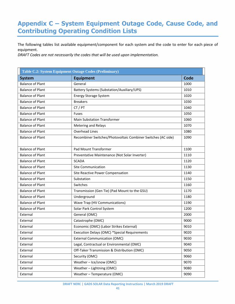
DRAFT NERC | GADS SOLAR Data Reporting Instructions | March 2019 DRAFT 41
Appendix C – System Equipment Outage Code, Cause Code, and
Contributing Operating Condition Lists
The following tables list available equipment/component for each system and the code to enter for each piece of equipment. DRAFT Codes are not necessarily the codes that will be used upon implementation. Table Error! No text of specified style in document..1: Use this f or Appendix Tables
Table C.2: System Equipment Outage Codes (Preliminary)
System Equipment Code Balance of Plant General 1000
Balance of Plant Battery Systems (Substation/Auxiliary/UPS) 1010
Balance of Plant Energy Storage System 1020
Balance of Plant Breakers 1030
Balance of Plant CT / PT 1040
Balance of Plant Fuses 1050
Balance of Plant Main Substation Transformer 1060
Balance of Plant Metering and Relays 1070
Balance of Plant Overhead Lines 1080
Balance of Plant Recombiner Switches/Photovoltaic Combiner Switches (AC side) 1090
Balance of Plant Pad Mount Transformer 1100
Balance of Plant Preventative Maintenance (Not Solar Inverter) 1110
Balance of Plant SCADA 1120
Balance of Plant Site Communication 1130
Balance of Plant Site Reactive Power Compensation 1140
Balance of Plant Substation 1150
Balance of Plant Switches 1160
Balance of Plant Transmission (Gen Tie) (Pad Mount to the GSU) 1170
Balance of Plant Underground 1180
Balance of Plant Wave Trap (HV Communications) 1190
Balance of Plant Solar Park Control System 1200
External General (OMC) 2000
External Catastrophe (OMC) 9000
External Economic (OMC) (Labor Strikes External) 9010
External Execution Delays (OMC) *Special Requirements 9020
External External Communication (OMC) 9030
External Legal, Contractual or Environmental (OMC) 9040
External Off-Taker Transmission & Distribution (OMC) 9050
External Security (OMC) 9060
External Weather – Ice/snow (OMC) 9070
External Weather – Lightning (OMC) 9080
External Weather – Temperature (OMC) 9090
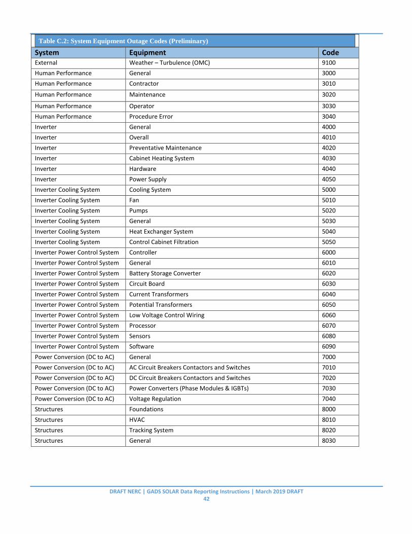
DRAFT NERC | GADS SOLAR Data Reporting Instructions | March 2019 DRAFT 42
Table C.2: System Equipment Outage Codes (Preliminary)
System Equipment Code External Weather – Turbulence (OMC) 9100
Human Performance General 3000
Human Performance Contractor 3010
Human Performance Maintenance 3020
Human Performance Operator 3030
Human Performance Procedure Error 3040
Inverter General 4000
Inverter Overall 4010
Inverter Preventative Maintenance 4020
Inverter Cabinet Heating System 4030
Inverter Hardware 4040
Inverter Power Supply 4050
Inverter Cooling System Cooling System 5000
Inverter Cooling System Fan 5010
Inverter Cooling System Pumps 5020
Inverter Cooling System General 5030
Inverter Cooling System Heat Exchanger System 5040
Inverter Cooling System Control Cabinet Filtration 5050
Inverter Power Control System Controller 6000
Inverter Power Control System General 6010
Inverter Power Control System Battery Storage Converter 6020
Inverter Power Control System Circuit Board 6030
Inverter Power Control System Current Transformers 6040
Inverter Power Control System Potential Transformers 6050
Inverter Power Control System Low Voltage Control Wiring 6060
Inverter Power Control System Processor 6070
Inverter Power Control System Sensors 6080
Inverter Power Control System Software 6090
Power Conversion (DC to AC) General 7000
Power Conversion (DC to AC) AC Circuit Breakers Contactors and Switches 7010
Power Conversion (DC to AC) DC Circuit Breakers Contactors and Switches 7020
Power Conversion (DC to AC) Power Converters (Phase Modules & IGBTs) 7030
Power Conversion (DC to AC) Voltage Regulation 7040
Structures Foundations 8000
Structures HVAC 8010
Structures Tracking System 8020
Structures General 8030

DRAFT NERC | GADS SOLAR Data Reporting Instructions | March 2019 DRAFT 43
Table C.2: Cause Codes (sample)
System Component Cause Code ID Cause Code Name
External Economic 0000 Reserve shutdown
Inactive States Inactive States 0002 Inactive Reserve Shutdown
Balance of Plant Electrical 3600 Switchyard transformers and associated cooling systems - external (OMC)
Balance of Plant Electrical 3601 Switchyard transformers and associated cooling systems - external (not OMC)
Balance of Plant Electrical 3610 Switchyard circuit breakers - external (not OMC)
Balance of Plant Electrical 3611 Switchyard circuit breakers - external (OMC)
Balance of Plant Electrical 3612 Switchyard system protection devices - external (OMC)
Balance of Plant Electrical 3613 Switchyard system protection devices - external (not OMC)
Balance of Plant Electrical 3618 Other switchyard equipment - external (not OMC)
Balance of Plant Electrical 3619 Other switchyard equipment - external (OMC)
Balance of Plant Electrical 3620 Main transformer
Balance of Plant Electrical 3621 Unit auxiliaries transformer
Balance of Plant Electrical 3622 Station service startup transformer
Balance of Plant Electrical 3629 Other switchyard or high voltage system problems - external
Balance of Plant Electrical 3630 400-700 volt transformers
Balance of Plant Electrical 3631 400-700 volt circuit breakers
Balance of Plant Electrical 3632 400-700 volt conductors and buses
Balance of Plant Electrical 3633 400-700 volt insulators
Balance of Plant Electrical 3634 400-700 volt protection devices
Balance of Plant Electrical 3639 Other 400-700 volt problems
Balance of Plant Electrical 3640 AC instrument power transformers
Balance of Plant Electrical 3641 AC Circuit breakers
Balance of Plant Electrical 3642 AC Conductors and buses
Balance of Plant Electrical 3643 AC Inverters
Balance of Plant Electrical 3644 AC Protection devices
Balance of Plant Electrical 3649 Other AC instrument power problems
Balance of Plant Electrical 3650 DC instrument power battery chargers
Balance of Plant Electrical 3651 DC circuit breakers
Balance of Plant Electrical 3652 DC conductors and buses
Balance of Plant Electrical 3653 DC protection devices
Balance of Plant Electrical 3659 Other DC power problems
Balance of Plant Electrical 3660 4000-7000 volt transformers
Balance of Plant Electrical 3661 4000-7000 volt circuit breakers
Balance of Plant Electrical 3662 4000-7000 volt conductors and buses
Balance of Plant Electrical 3663 4000-7000 volt insulators
Balance of Plant Electrical 3664 4000-7000 volt protection devices
Balance of Plant Electrical 3669 Other 4000-7000 volt problems

DRAFT NERC | GADS SOLAR Data Reporting Instructions | March 2019 DRAFT 44
Table C.2: Cause Codes (sample)
System Component Cause Code ID Cause Code Name
Balance of Plant Electrical 3670 12-15kV transformers
Balance of Plant Electrical 3671 12-15kV circuit breakers
Balance of Plant Electrical 3672 12-15kV conductors and buses
Balance of Plant Electrical 3673 12-15kV insulators
Balance of Plant Electrical 3674 12-15kV protection devices
Balance of Plant Electrical 3679 Other 12-15kV problems
Balance of Plant Electrical 3680 Other voltage transformers
Balance of Plant Electrical 3681 Other voltage circuit breakers
Balance of Plant Electrical 3682 Other voltage conductors and buses
Balance of Plant Electrical 3683 Other voltage insulators
Balance of Plant Electrical 3684 Other voltage protection devices
Balance of Plant Electrical 3689 Other voltage problems
Balance of Plant Electrical 3690 Station Service Power Distribution System, General
Balance of Plant Power Station Switchyard 3700 Power Station switchyard (non generating unit equipment)
Balance of Plant Power Station Switchyard 3710 Transmission line (connected to powerhouse switchyard to 1st Substation)
Balance of Plant Power Station Switchyard 3720 Transmission equipment at the 1st substation (see code 9300 if applicable)
Balance of Plant Power Station Switchyard 3730 Transmission equipment beyond the 1st substation (see code 9300 if applicable)
Balance of Plant Auxiliary Systems 3860 Fire protection system pumps
Balance of Plant Auxiliary Systems 3861 Fire protection system piping
Balance of Plant Auxiliary Systems 3862 Fire protection system valves
Balance of Plant Auxiliary Systems 3863 Fire protection system fouling
Balance of Plant Auxiliary Systems 3864 Fire protection system instrumentation and controls
Balance of Plant Auxiliary Systems 3869 Other fire protection system problems
Balance of Plant Miscellaneous (Balance of Plant)
3950 Process computer
Balance of Plant Miscellaneous (Balance of Plant)
3970 Distributive Control System (DCS) - process computer
Balance of Plant Miscellaneous (Balance of Plant)
3971 DCS - data highway
Balance of Plant Miscellaneous (Balance of Plant)
3972 DCS - hardware problems (including card failure)
Balance of Plant Miscellaneous (Balance of Plant)
3973 DCS - internal and termination wiring
Balance of Plant Miscellaneous (Balance of Plant)
3974 DCS - logic problems
Balance of Plant Miscellaneous (Balance of Plant)
3975 DCS - upgrades
Balance of Plant Miscellaneous (Balance of Plant)
3979 Other DCS problems
Balance of Plant Miscellaneous (Balance of Plant)
3980 Programmable Logic Controller (PLC)

DRAFT NERC | GADS SOLAR Data Reporting Instructions | March 2019 DRAFT 45
Table C.2: Cause Codes (sample)
System Component Cause Code ID Cause Code Name
Balance of Plant Miscellaneous (Balance of Plant)
3981 PLC - data highway
Balance of Plant Miscellaneous (Balance of Plant)
3982 PLC - hardware problems (including card failure)
Balance of Plant Miscellaneous (Balance of Plant)
3983 PLC - internal and termination wiring
Balance of Plant Miscellaneous (Balance of Plant)
3984 PLC - logic problems
Balance of Plant Miscellaneous (Balance of Plant)
3985 PLC - upgrades
Balance of Plant Miscellaneous (Balance of Plant)
3989 Other PLC problems
Balance of Plant Miscellaneous (Balance of Plant)
3995 Powerhouse heating and ventilating systems
Balance of Plant Miscellaneous (Balance of Plant)
3996 Air conditioning systems - rooms and areas
Balance of Plant Miscellaneous (Balance of Plant)
3998 Balance of plant overhaul/outage
Balance of Plant Miscellaneous (Balance of Plant)
3999 Other miscellaneous balance of plant problems
External Catastrophe 9000 Flood
External Catastrophe 9001 Drought
External Catastrophe 9010 Fire including wildfires, not related to a specific component
External Catastrophe 9020 Lightning
External Catastrophe 9025 Geomagnetic disturbance
External Catastrophe 9030 Earthquake
External Catastrophe 9031 Tornado
External Catastrophe 9035 Hurricane
External Catastrophe 9036 Storms (ice, snow, etc)
External Catastrophe 9040 Other catastrophe
External Economic 9150 Labor strikes company-wide problems or strikes outside the company's jurisdiction such as manufacturers (delaying repairs) or transportation (fuel supply) problems.
External Economic 9151 Labor strikes direct plant management grievances that result in a walkout or strike are under plant management control.
External Economic 9160 Other economic problems
External Economic 9180 Economic (for internal use at plants only)
External Economic 9181 Economic (for internal use at plants only)
External Economic 9182 Economic (for internal use at plants only)
External Economic 9183 Economic (for internal use at plants only)
External Economic 9184 Economic (for internal use at plants only)
External Economic 9185 Economic (for internal use at plants only)
External Economic 9186 Economic (for internal use at plants only)

DRAFT NERC | GADS SOLAR Data Reporting Instructions | March 2019 DRAFT 46
Table C.2: Cause Codes (sample)
System Component Cause Code ID Cause Code Name
External Economic 9187 Economic (for internal use at plants only)
External Economic 9188 Economic (for internal use at plants only)
External Economic 9189 Economic (for internal use at plants only)
External Economic 9190 Economic (for internal use at plants only)
External Economic 9191 Economic (for internal use at plants only)
External Economic 9192 Economic (for internal use at plants only)
External Economic 9193 Economic (for internal use at plants only)
External Economic 9194 Economic (for internal use at plants only)
External Economic 9195 Economic (for internal use at plants only)
External Economic 9196 Economic (for internal use at plants only)
External Economic 9197 Economic (for internal use at plants only)
External Economic 9198 Economic (for internal use at plants only)
External Economic 9199 Economic (for internal use at plants only)
External Miscellaneous (External) 9300 Transmission system problems other than catastrophes (do not include switchyard problems in this category; see codes 3600 to 3629, 3720 to 3730)
External Miscellaneous (External) 9310 Operator training
External Miscellaneous (External) 9320 Other miscellaneous external problems
Regulatory, Safety, Environmental
Regulatory 9504 Regulatory (environmental) proceedings and hearings - regulatory agency initiated
Regulatory, Safety, Environmental
Regulatory 9506 Regulatory (environmental) proceedings and hearings - intervenor initiated
Regulatory, Safety, Environmental
Regulatory 9510 Plant modifications strictly for compliance with new or changed regulatory requirements (scrubbers, cooling towers, etc.)
Regulatory, Safety, Environmental
Regulatory 9590 Miscellaneous regulatory (this code is primarily intended for use with event contribution code 2 to indicate that a regulatory-related factor contributed to the primary cause of the event)
Regulatory, Safety, Environmental
Other Operating Environmental Limitations
9690 Other miscellaneous operational environmental limits - fossil and nuclear
Regulatory, Safety, Environmental
Safety 9700 OSHA-related retrofit or inspection
Regulatory, Safety, Environmental
Safety 9720 Other safety problems
Personnel or Procedural Errors
Personnel or Procedural Errors
9900 Operator error
Personnel or Procedural Errors
Personnel or Procedural Errors
9910 Maintenance personnel error
Personnel or Procedural Errors
Personnel or Procedural Errors
9920 Contractor error
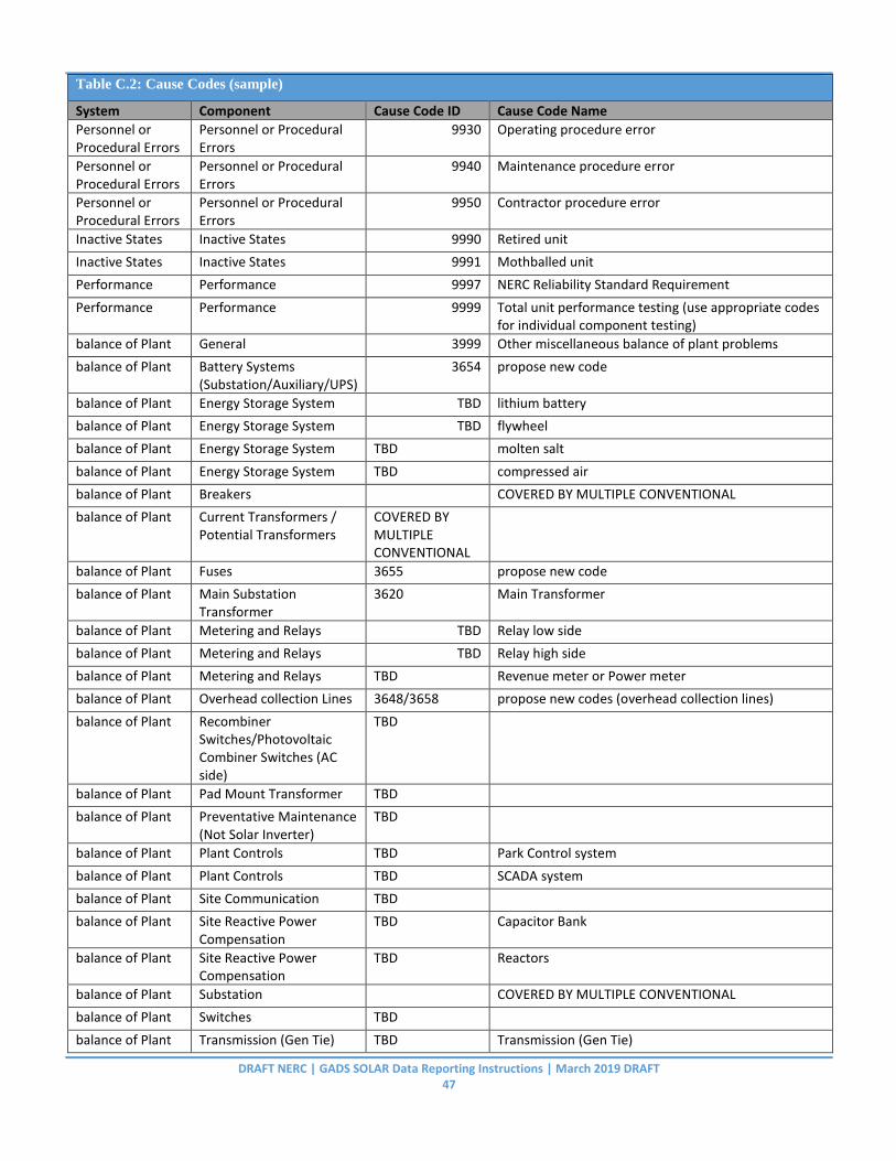
DRAFT NERC | GADS SOLAR Data Reporting Instructions | March 2019 DRAFT 47
Table C.2: Cause Codes (sample)
System Component Cause Code ID Cause Code Name
Personnel or Procedural Errors
Personnel or Procedural Errors
9930 Operating procedure error
Personnel or Procedural Errors
Personnel or Procedural Errors
9940 Maintenance procedure error
Personnel or Procedural Errors
Personnel or Procedural Errors
9950 Contractor procedure error
Inactive States Inactive States 9990 Retired unit
Inactive States Inactive States 9991 Mothballed unit
Performance Performance 9997 NERC Reliability Standard Requirement
Performance Performance 9999 Total unit performance testing (use appropriate codes for individual component testing)
balance of Plant General 3999 Other miscellaneous balance of plant problems
balance of Plant Battery Systems (Substation/Auxiliary/UPS)
3654 propose new code
balance of Plant Energy Storage System TBD lithium battery
balance of Plant Energy Storage System TBD flywheel
balance of Plant Energy Storage System TBD molten salt
balance of Plant Energy Storage System TBD compressed air
balance of Plant Breakers
COVERED BY MULTIPLE CONVENTIONAL
balance of Plant Current Transformers / Potential Transformers
COVERED BY MULTIPLE CONVENTIONAL
balance of Plant Fuses 3655 propose new code
balance of Plant Main Substation Transformer
3620 Main Transformer
balance of Plant Metering and Relays TBD Relay low side
balance of Plant Metering and Relays TBD Relay high side
balance of Plant Metering and Relays TBD Revenue meter or Power meter
balance of Plant Overhead collection Lines 3648/3658 propose new codes (overhead collection lines)
balance of Plant Recombiner Switches/Photovoltaic Combiner Switches (AC side)
TBD
balance of Plant Pad Mount Transformer TBD
balance of Plant Preventative Maintenance (Not Solar Inverter)
TBD
balance of Plant Plant Controls TBD Park Control system
balance of Plant Plant Controls TBD SCADA system
balance of Plant Site Communication TBD
balance of Plant Site Reactive Power Compensation
TBD Capacitor Bank
balance of Plant Site Reactive Power Compensation
TBD Reactors
balance of Plant Substation
COVERED BY MULTIPLE CONVENTIONAL
balance of Plant Switches TBD
balance of Plant Transmission (Gen Tie) TBD Transmission (Gen Tie)
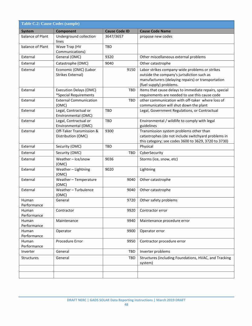
DRAFT NERC | GADS SOLAR Data Reporting Instructions | March 2019 DRAFT 48
Table C.2: Cause Codes (sample)
System Component Cause Code ID Cause Code Name
balance of Plant Underground collection lines
3647/3657 propose new codes
balance of Plant Wave Trap (HV Communications)
TBD
External General (OMC) 9320 Other miscellaneous external problems
External Catastrophe (OMC) 9040 Other catastrophe
External Economic (OMC) (Labor Strikes External)
9150 Labor strikes company-wide problems or strikes outside the company's jurisdiction such as manufacturers (delaying repairs) or transportation (fuel supply) problems.
External Execution Delays (OMC) *Special Requirements
TBD Items that cause delays to immediate repairs, special requirements are needed to use this cause code
External External Communication (OMC)
TBD other communication with off-taker where loss of communication will shut down the plant
External Legal, Contractual or Environmental (OMC)
TBD Legal, Government Regulations, or Contractual
External Legal, Contractual or Environmental (OMC)
TBD Environmental / wildlife to comply with legal guidelines
External Off-Taker Transmission & Distribution (OMC)
9300 Transmission system problems other than catastrophes (do not include switchyard problems in this category; see codes 3600 to 3629, 3720 to 3730)
External Security (OMC) TBD Physical
External Security (OMC) TBD CyberSecurity
External Weather – Ice/snow (OMC)
9036 Storms (ice, snow, etc)
External Weather – Lightning (OMC)
9020 Lightning
External Weather – Temperature (OMC)
9040 Other catastrophe
External Weather – Turbulence (OMC)
9040 Other catastrophe
Human Performance
General 9720 Other safety problems
Human Performance
Contractor 9920 Contractor error
Human Performance
Maintenance 9940 Maintenance procedure error
Human Performance
Operator 9900 Operator error
Human Performance
Procedure Error 9950 Contractor procedure error
Inverter General TBD Inverter problems
Structures General TBD Structures (including Foundations, HVAC, and Tracking system)
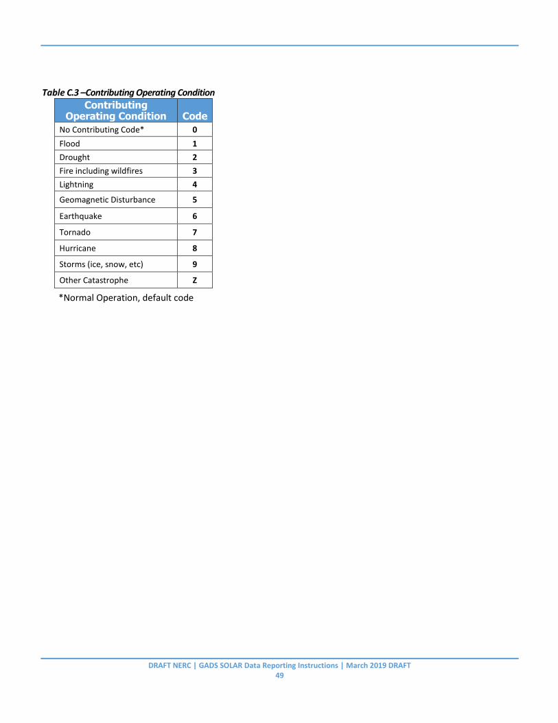
DRAFT NERC | GADS SOLAR Data Reporting Instructions | March 2019 DRAFT 49
Table C.3 –Contributing Operating Condition Contributing
Operating Condition Code
No Contributing Code* 0
Flood 1
Drought 2
Fire including wildfires 3
Lightning 4
Geomagnetic Disturbance 5
Earthquake 6
Tornado 7
Hurricane 8
Storms (ice, snow, etc) 9
Other Catastrophe Z
*Normal Operation, default code

DRAFT NERC | GADS SOLAR Data Reporting Instructions | March 2019 DRAFT 50
Appendix D – Terms and Definitions
General
Aggregate AC Inverter Clipping (MW)
The difference between Aggregate AC Nameplate and Summed Individual Inverter Capacity of the group is Aggregate AC Clipping. The difference between the point which the inverter can no longer convert DC power and the point of AC power below nameplate capacity summed for all inverters in the group.
For example, a system with a 1 MW Aggregate AC Nameplate, but an Individual Inverter Capacity (summed over the group) of 800 KW, the Aggregate AC Inverter clipping is .2 MW.
Aggregate DC to AC Ratio – Inverter Group Reporting For the inverter group. Check if it’s DC to AC ratio as AC as one. Represents the DC capacity of the solar panels to the AC capacity of the inverters. (If you get a software upgrade on the AC inverters, then you can re-calculate, but generally this is fixed for the inverter group.) Sample calculation: (sum of solar panel DC capacity) / (sum of inverter AC capacity) With a group of 5 inverters rated at 2 MW, that would be 10 MW AC With the 5 inverters linked to 2.1 MW solar panels per inverter, that would be 10.5 MW DC DC to AC Ratio = 10.5/10 = 1.05 For reporting to NERC, use AC value of “1” so that the results are in a “1.25” Is it valuable to show a separate DC value and AC value? Cause Code - Event Reporting The Cause code describes what happened during an event. See Appendix C for a list of Cause Codes. This can be related to Contributing Operating Condition, depending on the environment when the Event Start Date/Time occurs. Contributing Operating Condition - Event Reporting The Contributing Operating Condition is the underlying reason for an event. When an Event caused by the environment damages equipment, the Cause Code describes the equipment and Contributing Operating Condition describes the environment. Curtailment Curtailment is a general term used by the wind and solar industry for the involuntary reduction of plant maximum generation called for by the off-taker or transmission operator for a limit period of time. There are mainly two types, Reserve Shutdown (RS) and system emergency. RS is used when there is a lack of demand for the power or negative energy pricing. It may be reimbursed by the off-taker. A system emergency is a condition where voltage and or frequency stability are threatened. This condition is usually caused by line congestion and is never reimbursed. Most curtailments are caused by line congestion. Unless RS is identified, code these outages as Forced | OMC > Transmission. DC Input Type – Inverter Group Reporting This selection defines if the inverters are powered by solar PV alone, Solar PV with Energy Storage System (Battery), or Energy Storage System (Battery) alone. The selections are: Photovoltaic, Photovoltaic plus Energy Storage System (Battery), Energy Storage System (charged from AC side?). (In general, this is not the start of Energy Storage only reporting for NERC, as that is a separate effort.) This should be used as a guide of where the
DRAFT NERC | GADS SOLAR Data Reporting Instructions | March 2019 DRAFT 51
Energy Storage System is charged. Description - Event Reporting Verbal text expanding on Cause Code and Contributing Operating Condition to more fully describe the event. This can help NERC investigate common reasons that can be used to improve reliability. Energy Information Administration (EIA)
EIA information can be found at: www.eia.gov Energy Storage System Capacity (MW) This is the rated Capacity of energy storage group. (MW) Energy Storage System Energy (MWh) This is how much rated energy can be delivered over time. (MWh) Entity – Plant, Inverter Group, and Energy Storage Reporting
The principal organization that owns one or more plants. The entity is registered as a GOP (Generator Operator) with NERC and has an NCR number (NERC Compliance Registry) (or if voluntarily reporting a VR number (Voluntary Reporting)).
Entity ID - configuration The identifier of the Entity (NERC NCR number) used in Performance and Event reporting to reference owners of the plant. Event End Date/Time – Event Reporting The end time and date of an event in the Time Zone that is reported. The time is with a 24 hour clock. Event Start Date/Time – Event Reporting The start time and date of an event in the Time Zone that is reported. The time is with a 24 hour clock. Event Type – Event Reporting The type of event. Events are broken down into Forced, Maintenance, and Planned Events. Expected Generation (ExpE) – Performance Reporting
This is based on solar hours and solar radiation measured during intervals summed up for the month. Generally, this can be calculated using the Monthly Plane of Array x panel area x internal losses. Expected Generation is measured at the inverter group boundary. If referencing IEC 61724, this would be equivalent to the weather corrected expected generation.
Global Horizontal Irradiance – Inverter Group Reporting With new plants, use theoretical data from available data, for older plants, use on-site data.
http://rredc.nrel.gov/solar/glossary/gloss_g.html. (include metrics, possibly in Appendix E) total solar radiation; the
sum of Direct Normal Irradiance (DNI), Diffuse Horizontal Irradiance (DHI), and ground-reflected radiation; however, because ground reflected radiation is usually insignificant compared to direct and diffuse, for all practical purposes global radiation is said to be the sum of direct and diffuse radiation only: GHI = DHI + DNI * cos (Z) where Z is the solar zenith angle.
DRAFT NERC | GADS SOLAR Data Reporting Instructions | March 2019 DRAFT 52
Use NREL reference (or other reference) and use the average annual global horizontal irradiance. If you have real data for the past few years, that can be used. Gross Actual Generation (MWh) – Performance Reporting This is the total energy generated at the group level - in MWh. The Gross Actual Generation is the sum of all individual inverters at the AC side of the inverter. Individual Inverter Capacity (MW) – Inverter Group Reporting (not reported) The Individual Inverter Capacity is the limited capacity of the inverter below its Inverter AC Nameplate. This is associated with set point changes in software that limits the output of the inverter. This is used to calculate Aggregate AC Inverter Clipping. InterAnnual Variance of GHI – Inverter Group Reporting With new plants, use theoretical data from available data, for older plants, use on-site data. (Generally, 5 years of data is needed for annual standard deviation of irradiance.) GHI- Global Horizontal Irradiance – include link to NREL data (SolarAnywhere). (also, typical year and Inter-annual variance) (include metrics, possibly in Appendix E)
https://www.nrel.gov/docs/fy18osti/68886.pdf
With some knowledge about the inter-annual irradiance variability at a specific site, users can in principle select a particular experimental month to adequately characterize the solar resource. Although, ideally, such on-site measurement campaigns should last many years, practical reasons limit them to 1 year or less in the majority of cases, which increases the uncertainty in the long-term estimates. Likewise, with knowledge of the spatial variability over the area around a measurement station, users can evaluate the applicability of those measurements to a location some distance away
Inverter AC Nameplate (MW) – Inverter Group Reporting This is the MW nameplate for a single inverter system in the group. Inverter Group – Inverter Group, Performance, and Component Outage Reporting An inverter Group is a collection of inverters with the same manufacturer, designs, model number, capacity rating, and phase of construction. All inverters in the inverter group are required to be the same manufacturer, model, design, version, and Nameplate capacity (provide examples/diagrams) Inverter Group ID – Inverter Group, Performance, and Component Outage Reporting An identifier to track individual inverter groups in Component Outage and Performance reporting.
Inverter Group Installed Capacity (InvGrpCapacity) Enter the total capacity for the Inverter Group, in megawatts (MW). The Inverter Group Capacity is equal to the Number of Inverters multiplied by the applicable Single Inverter System Capacity MW. For example, one hundred 1 MW Type A inverters would have a system capacity of 100 MW. This field will automatically be calculated based on the inverter system capacity and the number of inverters. Validation: Inverter Group Capacity = InverterCount x Single Inverter System Capacity. Maximum Operating Temperature – Inverter Group Reporting
This is the Maximum operating temperature (Celsius) that the inverter will stop producing energy. Minimal Operating Temperature – Inverter Group Reporting
This is the minimal operating temperature (Celsius) that the inverter will stop producing energy. Minimum Irradiance – Inverter Group Reporting

DRAFT NERC | GADS SOLAR Data Reporting Instructions | March 2019 DRAFT 53
This is the minimum amount of irradiance needed for the inverter to provide stable panel and inverter performance. (W/m^2) As an example, a typical value is 85 W/m^2. This is used to also show what irradiance is needed to start performance reporting. Also, this will show differentiation between changing technologies at the panel level. Minimum Voltage – Inverter Group Reporting This is the minimum amount of voltage needed for the inverter to provide energy. (Volts) Since the 85 W/m^2 is usually enough to provide enough voltage for the inverter, this shows how much voltage is actually needed to energize the inverters themselves. This should be the minimum cut-in voltage of the inverter. Monthly Plane of Array – Performance Reporting Monthly Plane of Array (MWh/m^2) value Lost MW Capacity – Event Reporting This is the maximum capacity MW loss due to an event. This can differ from MW output at time of event. This is the amount of MW that are not available due to the event at the peak capacity during the event. MW Output at time of event – Event Reporting This is the MW output at the Event Start Date/Time. If the event start date/time is at night, MW output at time of event is 0 MW. Net Actual Generation (MWh) – Performance Reporting The Net Actual Generation is the energy delivered at the revenue meter or Point of Interconnection. It is possible to have a negative net actual generation if the group’s station service or auxiliary loads are greater than the total generation from the inverters. (clarify that group data will need to be divided by total sent to grid)
Net Dependable Capacity (NDC) (equivalent to NMC x Capacity Factor) NDC is the actual generating capability at the revenue meter less capacity losses. These losses may include, but are not limited to, losses from no solar, low solar, high solar, derated solar (less than rated capacity), or losses that occur outside the manufacturer’s operating specifications (temperature, electrical & etc.). Another way of looking at NDC is the Capacity of the Inverter at 100% availability while running within the manufacture’s specification with the fuel source available (Solar). For example, if the NMC is 100 MW and the losses from all Solar problems is 40% then the NDC can be calculated as 100 MW x (1 ‐ 0.40). Our NDC would be 60 MW. When using the Capacity Factor, you can use the Standard Capacity Factor or the Resource Capacity Factor (expand text to clarify using both capacity factors with relation to NDC)
NDC may also be calculated as follows: [(Actual Generation) + (Inverter specific losses) + (reserve shutdown) + (Site outages such as off‐taker problems + balance of plant, not Solar related)] / (PH). Net Maximum Capacity (MW) – Performance Reporting This is the actual generating capability at the inverter boundary (MW) usually at the revenue meter. This is equal to the Inverter Group Installed Capacity less any electrical losses such as transformation losses, line losses, and losses due to transmission between the inverter and revenue meter Net Maximum Capacity (NMC) (MW) – Performance Reporting NMC is the actual maximum generating capability at the revenue meter and is equal to the Aggregate AC Nameplate (Inverter Group Installed Capacity) less any electrical losses. These losses may include, but are not

DRAFT NERC | GADS SOLAR Data Reporting Instructions | March 2019 DRAFT 54
limited to, transformation losses, line losses, and other auxiliary losses between the Inverter and revenue meter (usually equivalent to the point of interconnect).
For example, if the Aggregate AC Nameplate (Inverter Group Installed Capacity) is 410 MW and the loss is 2% then the NMC can be calculated as 410 MW x (1 ‐ 0.02). The NMC is 402 MW. Off-Taker
The entity that receives the power produced by the plant. This is not necessarily the purchaser of the power, but the entity that takes control of the power when it leaves the plant boundary, such as a transmission operator. The Off-Taker could also be called the transmission provider or balancing authority.
Panel Tracking – Inverter Group Reporting. Panel Tracking shows what kind of panel tracking is used. The selections are: Fixed Panels, Single Axis (Azimuth) tracking, or Dual Axis tracking. Performance ratio - Performance Reporting
As performance on a month by month basis to track degradation of panels, as well as temperature and ambient conditions. This is ratio of actual generation to the capacity of the inverter. Reference document: NREL Weather Corrected Performance Ratio: https://www.nrel.gov/docs/fy13osti/57991.pdf Reference document: IEC 61724 https://webstore.iec.ch/publication/33622
Plant A plant is defined as a collection of Solar inverter groups and associated energy storage groups at a single physical location. See Chapter 2 for Plant Outline. Single Manager of a location is an indicator plant. Plants may have multiple revenue meters. (update based on definition above, plus examples)
Plant ID - Configuration The identifier of the Plant used in performance and Event reporting to reference owners of the plant.
Plant Total Installed Capacity MW The combined capacity of Inverter Group Installed Capacity defined as a solar generating facility. Potential MWH production Loss – Event Reporting The amount of Megawatt Hours of production that was lost during an event. Generally, this is the expected generation that was not produced during the event. Reserve Inverter Capacity – Reserve Capacity is the Aggregate AC Nameplate minus the Inverter System Capacity. It is capacity of the Inverters within a group that are available but not under contract. These Inverters must be available and connected to a group, not in an inactive state, and their output can be temporarily added to the sub‐group at a moment’s notice in the event that another Inverter becomes unavailable. Reserve Capacity is not reported but is a calculated field. The purpose of reserve capacity is to allow producers to use inverters that may have been phased out but are still in good working condition to improve their availability when Inverters in the main generating group are in an unavailable state due to an outage or to maximize output within contract limits. For example: Total Inverters = 205, Inverter AC Nameplate = 2MW

DRAFT NERC | GADS SOLAR Data Reporting Instructions | March 2019 DRAFT 55
Aggregate AC Nameplate = 410 MW (205 * 2MW) Inverter System Capacity = Contracted PPA capacity = 400 MW Reserve Capacity = 10 MW (410 MW – 400 MW).
Resource Capacity Factor – For a plant, calculated by sum of inverter group Net Actual Generation / (sum of Inverter Group Capacity x Active Solar Inverter hours). This can be used to compare solar generators with each other since generation only happens during solar hours. (add similar definition for inverter group resource capacity factor-plus example)
Revenue Meter The revenue meter is a device used to measure the electricity generated from a plant, group, depending on the plant configuration. The revenue meter accounts for the energy delivered to the transmission or distribution system and is normally owned by the off‐taker. This defines the Net Energy delivered to the grid, by a transmission agreement. You can have multiple revenue meters at a single Plant. Single Inverter System Capacity MW (InvSystemMW) (Column 13) The System MW rating of the Inverter based on DC input. This includes temperature set points and other internal inverter limits as the site is set up. All inverters in the inverter group are required to be the same manufacturer, model, design, version, and AC capacity based on average or similar DC input. Solar Regime Environment– Inverter Group Reporting The Solar Regime Environment describes the general type of the solar array. See Appendix F Table 5 for Solar Regime list. Standard Capacity Factor – calculated For a plant, calculated by sum of inverter group Net Actual Generation / (sum of Inverter Group Capacity * month hours (24 hours basis)). This can be used since the 24-hour comparison can be used to compare with other non-solar generators. (add similar definition for inverter group capacity factor-plus example) Stowing Wind Speed (if tracking) – Inverter Group Reporting
If panels are tracking, this is the wind speed that tracking is stopped, and panels are adjusted for the wind to prevent damage. (meters/second) System – Equipment Outage Detail Code - Equipment Outage Reporting The System-Equipment Outage Detail Code is the equipment that failed during an outage. Generally, when an Outage occurs, the System and Equipment area in the Group System-Equipment Outage Detail Code is the same as the System and Equipment in a Plant Cause Code Event. Time Zone – Event Reporting
The Time Zone where the reporting is tracked. If a plant is in one time zone, but the event times are reported in another time zone, use the time zone that is used in reporting.

DRAFT NERC | GADS SOLAR Data Reporting Instructions | March 2019 DRAFT 56
Appendix E – Equations
Different sets of performance equations are listed. A description of these sections is below.
1. System and Unit Calculations – These equations calculate the individual resource and equipment performance by inverter group(s) that have similar inverter capacities. These equations also include OMC hours.
2. System and Unit Calculations without OMC Hours – These equations calculate the individual resource and equipment performance by inverter group(s) that have the same, or very similar, inverter capacities. These equations do not include OMC hours.
3. Generation Equations – These equations calculate the performance statistics based on Generation measures instead of time measures.
In most cases, “resource” performance factors and rates take into account all outages and hours. These include, but are not limited to, outages from resource (Solar) unavailability, equipment failures, off‐taker events, weather, and any other non‐equipment outages. Resource equations are primarily used by resource planners integrating Solar energy into the bulk power supply.
Equipment performance factors and rates take into account Calendar Hours, Active Hours, and all outages pertaining to equipment that fall within and outside of management control for a given study. Equipment performance equations are used by plant managers to monitor performance behind the plant boundary. The selection of formulas below represent a small selection of actual metrics that can be calculated.
SECTION 1: System Calculations (for groups) 1.A. System Performance Factors These are performance rates and factors that highlight the effect of the resource and are primarily used by planners or from a system view. In order to do that, Resource Unavailable Inverter Hours Day (RUIHD) and Resource Unavailable Inverter Hours Night (RUIHN) are treated as forced outage hours. This defines the ability of the technology to deliver power to the bulk power system. Time-based Metrics: Reported hours are split into Daytime and Nighttime hours. To get the system equations, we need to combine day and night hours. In General, these Hourly equations will appear as: Total Hours = Daytime Hours + Nighttime Hours Each of these give the underlying hours for our System and Unit Equations below. Active Inverter Hours (AIH) Service Inverter Hours (SIH) Forced Outage Inverter Hours (FIH) Maintenance Outage Inverter Hours (MIH) Planned Outage Inverter Hours (PIH) Resource Unavailable Inverter Hours (RUIH)

DRAFT NERC | GADS SOLAR Data Reporting Instructions | March 2019 DRAFT 57
Equivalent Forced Derate Inverter Hours (EFDIH) Equivalent Maintenance Derate Inverter Hours (EMDIH) Equivalent Planned Derate Inverter Hours (EPDIH) Equivalent Partial Reserve Shutdown Inverter Hours (EPRSIH) (usually included with Service Hours, so must remove them in Forced Outage Rates denominators) *we add Equivalent Partial Resource Unavailable Inverter Hours (*EPRUIH)* (usually included with Service Hours, so must be removed in numerators where Resource Unavailable Inverter Hours exist) Similar rollups occur with OMC Inverter hours and Delay Inverter hours.
System Equations: 1.A.1. System Equivalent Availability Factor (SEAF) % of month that the plant was available.
𝑆𝐸𝐴𝐹 = [𝐴𝐼𝐻 − (𝐹𝐼𝐻 + 𝑀𝐼𝐻 + 𝑃𝐼𝐻 + 𝐸𝐹𝐷𝐼𝐻 + 𝐸𝑀𝐷𝐼𝐻 + 𝐸𝑃𝐷𝐼𝐻 + 𝑅𝑈𝐼𝐻 + 𝐸𝑃𝑅𝑈𝐼𝐻)]
𝐴𝐼𝐻× 100
≈ (100 − 𝑆𝐸𝑈𝐹)

DRAFT NERC | GADS SOLAR Data Reporting Instructions | March 2019 DRAFT 58
1.A.2. System Equivalent Unavailability Factor (SEUF)
% of month that the plant was unavailable.
𝑆𝐸𝑈𝐹 = (𝐹𝐼𝐻 + 𝑀𝐼𝐻 + 𝑃𝐼𝐻 + 𝐸𝐹𝐷𝐼𝐻 + 𝐸𝑀𝐷𝐼𝐻 + 𝐸𝑃𝐷𝐼𝐻 + 𝑅𝑈𝐼𝐻 + 𝐸𝑃𝑅𝑈𝐼𝐻)
𝐴𝐼𝐻× 100
≈ (100 − 𝑆𝐸𝐴𝐹)
1.A.3. System Equivalent Forced Outage Factor (SEFOF)
% of month that the plant was forced off line.
𝑆𝐸𝐹𝑂𝐹 =(𝐹𝐼𝐻 + 𝐸𝐹𝐷𝐼𝐻 + 𝑅𝑈𝐼𝐻 + 𝐸𝑃𝑅𝑈𝐼𝐻)
𝐴𝐼𝐻× 100
1.A.4. System Equivalent Forced Outage Rate
𝑆𝐸𝐹𝑂𝑅 = (𝐹𝐼𝐻 + 𝐸𝐹𝐷𝐼𝐻 + 𝑅𝑈𝐼𝐻 + 𝐸𝑃𝑅𝑈𝐼𝐻)
𝐹𝐼𝐻 + 𝑆𝐼𝐻 + 𝑅𝑈𝐼𝐻× 100
1.A.5. Resource Unavailable Equivalent Forced Outage Rate
𝑅𝑈𝐸𝐹𝑂𝑅 = (𝑅𝑈𝐼𝐻 + 𝐸𝑃𝑅𝑈𝐼𝐻)
𝐹𝐼𝐻 + 𝑅𝑈𝐼𝐻 + (𝑆𝐼𝐻 − 𝐸𝑃𝑅𝑆𝐼𝐻)× 100
1.A.6. System Equivalent Resource Unavailability Factor
𝑆𝐸𝑅𝑈𝐹 =(𝑅𝑈𝐼𝐻 + 𝐸𝑃𝑅𝑈𝐼𝐻)
𝐴𝐼𝐻× 100
1.A.7. System Equivalent Resource Availability Factor
𝑆𝐸𝑅𝐴𝐹 =𝐴𝐼𝐻 − (𝑅𝑈𝐼𝐻 + 𝐸𝑃𝑅𝑈𝐼𝐻)
𝐴𝐼𝐻× 100
Unit Equations: Unit equations disregard the Resource Unavailable term from the outage hours. 2.A.1. Unit Equivalent Availability Factor (EAF) % of month that the plant was available.
𝐸𝐴𝐹 = [𝐴𝐼𝐻 − (𝐹𝐼𝐻 + 𝑀𝐼𝐻 + 𝑃𝐼𝐻 + 𝐸𝐹𝐷𝐼𝐻 + 𝐸𝑀𝐷𝐼𝐻 + 𝐸𝑃𝐷𝐼𝐻)]
𝐴𝐼𝐻× 100
≈ (100 − 𝐸𝑈𝐹)

DRAFT NERC | GADS SOLAR Data Reporting Instructions | March 2019 DRAFT 59
2.A.2. Unit Equivalent Unavailability Factor (EUF)
% of month that the plant was unavailable.
𝐸𝑈𝐹 = (𝐹𝐼𝐻 + 𝑀𝐼𝐻 + 𝑃𝐼𝐻 + 𝐸𝐹𝐷𝐼𝐻 + 𝐸𝑀𝐷𝐼𝐻 + 𝐸𝑃𝐷𝐼𝐻)
𝐴𝐼𝐻× 100
≈ (100 − 𝐸𝐴𝐹) 2.A.3. Unit Equivalent Forced Outage Factor (EFOF)
𝐸𝐹𝑂𝐹 =(𝐹𝐼𝐻 + 𝐸𝐹𝐷𝐼𝐻)
𝐴𝐼𝐻× 100
2.A.4. Unit Equivalent Forced Outage Rate
𝐸𝐹𝑂𝑅 = (𝐹𝐼𝐻 + 𝐸𝐹𝐷𝐼𝐻)
𝐹𝐼𝐻 + (𝑆𝐼𝐻 − 𝐸𝑃𝑅𝑆𝐼𝐻) + 𝑅𝑈𝐼𝐻× 100
Generation Metrics: Generation metrics are based on Energy Generation terms in megawatt-hours instead of hours. Since variable generators change capacity continuously, these metrics give better indications of performance than does raw hours. Calculations are based on these data items that are currently collected: Expected Generation: EG (Reported in Monthly Performance) Gross Maximum Generation: GMG = Active Inverter Hours (reported in Monthly Performance) x Inverter Group Installed Capacity Gross Maximum Capacity: GMC = Inverter Group Installed Capacity (Reported in Group Configuration) Gross Actual Generation: GAG (Reported in Monthly Performance) (measured at Inverter) Net Actual Generation: NAG (Reported in Monthly Performance) (measured at Revenue Meter) Net Maximum Capacity: NMC (Reported in Monthly Performance) 3.A.1. Unit Performance Index (PI) The fraction of generation that was actually produced against the expected generation.
𝑃𝐼 = 𝐺𝐴𝐺
𝐸𝐺× 100
3.A.1.b System Performance Index (SPI)
𝑃𝐼 = 𝐺𝐴𝐺
𝐺𝑀𝐺× 100
3.A.2. System Resource Unavailable Generation Factor (RUGF) The
𝑅𝑈𝐺𝐹 = 1 − 𝐸𝐺
𝐺𝑀𝐺× 100

DRAFT NERC | GADS SOLAR Data Reporting Instructions | March 2019 DRAFT 60
3.A.2. System Resource Available Generation Factor (RAGF) (For resource calculations, Gross Maximum must be in the denominator)
𝑅𝐴𝐺𝐹 = 𝐸𝐺
𝐺𝑀𝐺× 100
3.A.8 Net Capacity Factor (NCF) The Net Energy that was produced in a given period as a fraction of the Net Maximum Generation.
𝑁𝐶𝐹 = 𝑁𝐴𝐺
𝑁𝑀𝐺× 100 = 𝑁𝐴𝐺
𝑁𝐴𝐺
𝐴𝐼𝐻 𝑥 𝐺𝑀𝐶x100
3.A.9 Net Output Factor (NOF) The Net Energy that was produced in a given period as a fraction of the Net Maximum Generation.

DRAFT NERC | GADS SOLAR Data Reporting Instructions | March 2019 DRAFT 61
Appendix F – Reference Tables
If you would like to add an item to any of the tables, please e‐mail your request to GADS at [email protected]
Table 1 - Country Country Name Abbreviation Canada CA Mexico MX United States US Other OT
Table 2 – States-US United States
Name Abb. Name Abb. Name Abb. Alabama AL Kentucky KY Oklahoma OK Alaska AK Louisiana LA Oregon OR American Samoa AS Maine ME Pennsylvania PA Arizona AZ Maryland MD Puerto Rico PR Arkansas AR Massachusetts MA Rhode Island RI California CA Michigan MI South Carolina SC Colorado CO Minnesota MN South Dakota SD Connecticut CT Mississippi MS Tennessee TN Delaware DE Missouri MO Texas TX District of Columbia DC Montana MT Utah UT Florida FL Nebraska NE Vermont VT Georgia GA Nevada NV Virgin Islands VI Guam GU New Hampshire NH Virginia VA Hawaii HI New Jersey NJ Washington WA Idaho ID New Mexico NM West Virginia WV Illinois IL New York NY Wisconsin WI Indiana IN North Carolina NC Wyoming WY Iowa IA North Dakota ND Kansas KS Ohio OH
Table 3 – Provinces-Canada Canada
Name Abb. Name Abb.
Alberta AB Nova Scotia NS British Columbia BC Ontario ON Manitoba MB Prince Edward Island PE New Brunswick NB Quebec QC Newfoundland and Labrador NF Saskatchewan SK
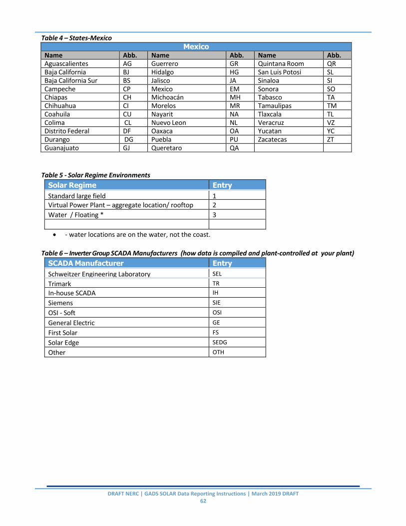
DRAFT NERC | GADS SOLAR Data Reporting Instructions | March 2019 DRAFT 62
Table 4 – States-Mexico Mexico
Name Abb. Name Abb. Name Abb. Aguascalientes AG Guerrero GR Quintana Room QR Baja California BJ Hidalgo HG San Luis Potosi SL Baja California Sur BS Jalisco JA Sinaloa SI Campeche CP Mexico EM Sonora SO Chiapas CH Michoacán MH Tabasco TA Chihuahua CI Morelos MR Tamaulipas TM Coahuila CU Nayarit NA Tlaxcala TL Colima CL Nuevo Leon NL Veracruz VZ Distrito Federal DF Oaxaca OA Yucatan YC Durango DG Puebla PU Zacatecas ZT Guanajuato GJ Queretaro QA
Table 5 - Solar Regime Environments
Solar Regime Entry
Standard large field 1 Virtual Power Plant – aggregate location/ rooftop 2
Water / Floating * 3
- water locations are on the water, not the coast.
Table 6 – Inverter Group SCADA Manufacturers (how data is compiled and plant-controlled at your plant)
SCADA Manufacturer Entry
Schweitzer Engineering Laboratory SEL
Trimark TR
In-house SCADA IH
Siemens SIE
OSI - Soft OSI
General Electric GE
First Solar FS
Solar Edge SEDG
Other OTH

DRAFT NERC | GADS SOLAR Data Reporting Instructions | March 2019 DRAFT 63
Table 7 – Inverter Group Inverter Manufacturers
Inverter Manufacturer Entry
ABB ABB
Canadian Solar CANSO
Chint Power Systems CHINT
Delta Energy Systems DELT
Fronius International FRON
General Electric GE
Ginlong - Solis GSOL
Huawei Technologies HUAW
Kaco New Energy KACO
Other OTHIM
Power Electronics PWR
PowerOne PONE
SATCON SATC
Schneider Electric SCHN
Selectria SELT
SMA SMA
SolarEdge SEDG
SunGrow PowerSupply SGROW
TMEIC TMEIC
Yaskawa YASK
Table 8 – Energy Storage Manufacturer (not just battery, but company compiling Energy Storage system)
Energy Storage Manufacturer Entry
Beacon BEAC Build Your Dreams BYD
EOS EOS
Lockheed Martin LKM
Other OTHM
Samsung SDI SDI
SolarEdge SEDG
Sun Catalyx SCAT
Tesla TES
Table 9 – Energy Storage Inverter Manufacturer
Energy Storage Inverter Manufacturer Entry
ABB
ABB
Canadian Solar CANSO
Chint Power systems CHINT
Delta Energy Systems DELT
Fronius International FRON
General Electric GE

DRAFT NERC | GADS SOLAR Data Reporting Instructions | March 2019 DRAFT 64
Energy Storage Inverter Manufacturer Entry
Ginlong-Solis
GSOL
Huawei Technologies HUAW
Kaco New Energy KACO
Other OTHESM
Selectria SELT
Table 10 – Energy Storage Type Energy Storage Type Entry
Battery - Flow FLB Battery – Lithium Ion LIB
Battery - Other OTHB
Capacitor CAP
Compressed Gas CE
Flywheel FW
Gravity Weight GW
Hydrogen Fuel Cell FC
Other OTHS
Thermal / Heat TH
Table 11 – Panel Tracking Type Panel Tracking Type Entry
Fixed – no tracking FIXED
Single Axis SINGLE
Dual Axis DUAL
Table 12 – Energy Storage Connection Type Energy Storage Connection Type Entry
AC – Connection between Inverters and grid connection
AC
DC – Connection behind the Inverters DC
Table 13 – Month Reference Monthly Summaries
01 – January 07 – July 02 ‐ February 08 – August
03 – March 09 – September
04 – April 10 – October
05 – May 11 – November
06 ‐ June 12 ‐ December
Table 14 – Availability Status
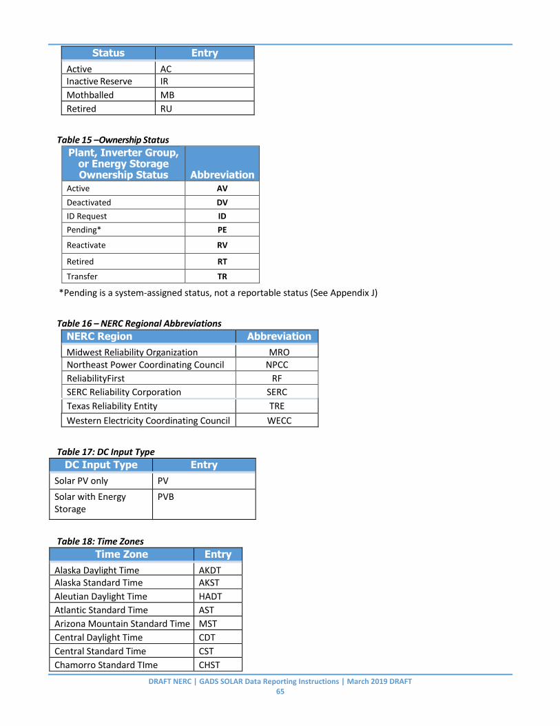
DRAFT NERC | GADS SOLAR Data Reporting Instructions | March 2019 DRAFT 65
Status Entry
Active AC Inactive Reserve IR
Mothballed MB
Retired RU
Table 15 –Ownership Status Plant, Inverter Group,
or Energy Storage Ownership Status Abbreviation
Active AV
Deactivated DV
ID Request ID
Pending* PE
Reactivate RV
Retired RT
Transfer TR
*Pending is a system-assigned status, not a reportable status (See Appendix J)
Table 16 – NERC Regional Abbreviations
NERC Region Abbreviation
Midwest Reliability Organization MRO Northeast Power Coordinating Council NPCC
ReliabilityFirst RF
SERC Reliability Corporation SERC
Texas Reliability Entity TRE
Western Electricity Coordinating Council WECC
Table 17: DC Input Type
DC Input Type Entry
Solar PV only PV
Solar with Energy Storage
PVB
Table 18: Time Zones
Time Zone Entry
Alaska Daylight Time AKDT Alaska Standard Time AKST
Aleutian Daylight Time HADT
Atlantic Standard Time AST
Arizona Mountain Standard Time MST
Central Daylight Time CDT
Central Standard Time CST
Chamorro Standard TIme CHST

DRAFT NERC | GADS SOLAR Data Reporting Instructions | March 2019 DRAFT 66
Time Zone Entry
Eastern Daylight Time EDT
Eastern Standard Time EST
Hawaii Standard Time HST
Mountain Standard Time MST
Pacific Daylight Time PDT
Pacific Standard Time PDT
Samoa Standard Time SST
Table 20: Event Types
Event Type Entry
Forced Outage FO Maintenance Outage MO
Planned Outage PO
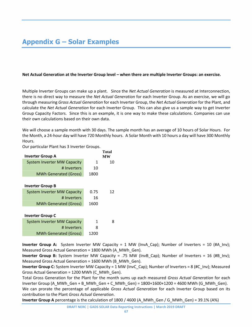
DRAFT NERC | GADS SOLAR Data Reporting Instructions | March 2019 DRAFT 67
Appendix G – Solar Examples
Net Actual Generation at the Inverter Group level – when there are multiple Inverter Groups: an exercise. Multiple Inverter Groups can make up a plant. Since the Net Actual Generation is measured at Interconnection, there is no direct way to measure the Net Actual Generation for each Inverter Group. As an exercise, we will go through measuring Gross Actual Generation for each Inverter Group, the Net Actual Generation for the Plant, and calculate the Net Actual Generation for each Inverter Group. This can also give us a sample way to get Inverter Group Capacity Factors. Since this is an example, it is one way to make these calculations. Companies can use their own calculations based on their own data. We will choose a sample month with 30 days. The sample month has an average of 10 hours of Solar Hours. For the Month, a 24-hour day will have 720 Monthly hours. A Solar Month with 10 hours a day will have 300 Monthly Hours. Our particular Plant has 3 Inverter Groups.
Inverter Group A Total
MW
System Inverter MW Capacity 1 10
# Inverters 10 MWh Generated (Gross) 1800
Inverter Group B
System Inverter MW Capacity 0.75 12
# Inverters 16 MWh Generated (Gross) 1600
Inverter Group C
System Inverter MW Capacity 1 8
# Inverters 8 MWh Generated (Gross) 1200
Inverter Group A: System Inverter MW Capacity = 1 MW (InvA_Cap); Number of Inverters = 10 (#A_Inv); Measured Gross Actual Generation = 1800 MWh (A_MWh_Gen). Inverter Group B: System Inverter MW Capacity = .75 MW (InvB_Cap); Number of Inverters = 16 (#B_Inv); Measured Gross Actual Generation = 1600 MWh (B_MWh_Gen). Inverter Group C: System Inverter MW Capacity = 1 MW (InvC_Cap); Number of Inverters = 8 (#C_Inv); Measured Gross Actual Generation = 1200 MWh (C_MWh_Gen). Total Gross Generation for the Plant for the month sums up each measured Gross Actual Generation for each Inverter Group (A_MWh_Gen + B_MWh_Gen + C_MWh_Gen) = 1800+1600+1200 = 4600 MWh (G_MWh_Gen). We can prorate the percentage of applicable Gross Actual Generation for each Inverter Group based on its contribution to the Plant Gross Actual Generation. Inverter Group A percentage is the calculation of 1800 / 4600 (A_MWh_Gen / G_MWh_Gen) = 39.1% (A%)
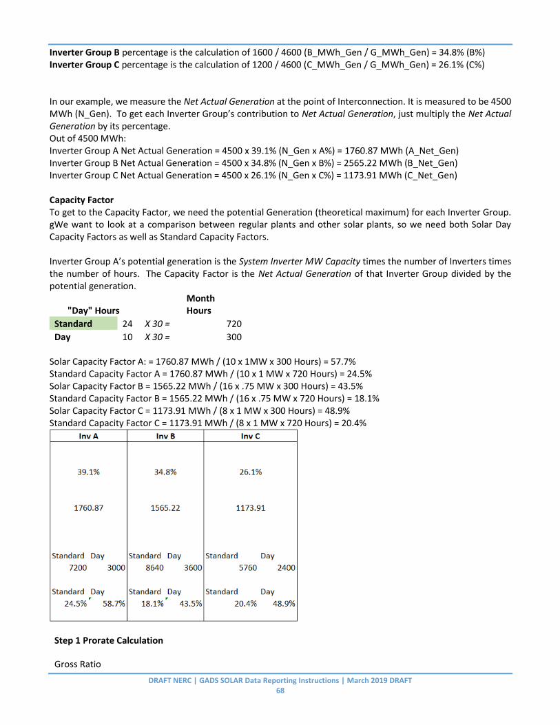
DRAFT NERC | GADS SOLAR Data Reporting Instructions | March 2019 DRAFT 68
Inverter Group B percentage is the calculation of 1600 / 4600 (B_MWh_Gen / G_MWh_Gen) = 34.8% (B%) Inverter Group C percentage is the calculation of 1200 / 4600 (C_MWh_Gen / G_MWh_Gen) = 26.1% (C%) In our example, we measure the Net Actual Generation at the point of Interconnection. It is measured to be 4500 MWh (N_Gen). To get each Inverter Group’s contribution to Net Actual Generation, just multiply the Net Actual Generation by its percentage. Out of 4500 MWh: Inverter Group A Net Actual Generation = 4500 x 39.1% (N_Gen x A%) = 1760.87 MWh (A_Net_Gen) Inverter Group B Net Actual Generation = 4500 x 34.8% (N_Gen x B%) = 2565.22 MWh (B_Net_Gen) Inverter Group C Net Actual Generation = 4500 x 26.1% (N_Gen x C%) = 1173.91 MWh (C_Net_Gen) Capacity Factor To get to the Capacity Factor, we need the potential Generation (theoretical maximum) for each Inverter Group. gWe want to look at a comparison between regular plants and other solar plants, so we need both Solar Day Capacity Factors as well as Standard Capacity Factors. Inverter Group A’s potential generation is the System Inverter MW Capacity times the number of Inverters times the number of hours. The Capacity Factor is the Net Actual Generation of that Inverter Group divided by the potential generation.
"Day" Hours
Month Hours
Standard 24 X 30 = 720
Day 10 X 30 = 300 Solar Capacity Factor A: = 1760.87 MWh / (10 x 1MW x 300 Hours) = 57.7% Standard Capacity Factor A = 1760.87 MWh / (10 x 1 MW x 720 Hours) = 24.5% Solar Capacity Factor B = 1565.22 MWh / (16 x .75 MW x 300 Hours) = 43.5% Standard Capacity Factor B = 1565.22 MWh / (16 x .75 MW x 720 Hours) = 18.1% Solar Capacity Factor C = 1173.91 MWh / (8 x 1 MW x 300 Hours) = 48.9% Standard Capacity Factor C = 1173.91 MWh / (8 x 1 MW x 720 Hours) = 20.4%
Step 1 Prorate Calculation
Gross Ratio

DRAFT NERC | GADS SOLAR Data Reporting Instructions | March 2019 DRAFT 69
=X_MWh Gen/(A_Mwh_Gen+B_MWh_Gen+C_MWh_Gen)
Group Prorated Net Gen (MWh) = POI_MWh*X_G_Ratio
Step 2 Capacity Factor Calc
potential generation (MWh)
=Inv_Cap* #_Inv* Hours
Group Cap Factor
=X_Grp_Net/Pot_Gen Weighted Hours / Generation - continuation of exercise (explain the method of getting allocation of energy weighted by outage type) If we have Expected Generation of 2000 MWh but the Gross Actual Generation of 1800 MWh, we have 200 MWh that apply to when the Inverter A is not generating. We record these outage hours for Inverter Group A: Partial Reserve Shutdown Hours – Day: 20 Forced Outage Hours – Day: 20 Maintenance Outage Hours – Day: 15 Planned Hours – Day: 2 Other (Undefined) – Day: 3 If we allocate all 60 hours equally to the 200 MWh, that would be 3.33 MWh averaged. However, we know that some outages occur during peak Capacity times and other outages occur at times when the Inverter Group is at less than full Capacity. It makes sense to weight the hours to increase impact of outages that occur during high capacity and weight the hours less impact for outages that occur during low capacity hours.
Partial Reserve Shutdown Hours-Day 125% 20 83
Forced Outage Hours-Day 125% 20 83
Maintenance Hours-Day 25% 15 13
Planned Hours-Day 25% 2 2
Other (Undefined) - Day 3 19

DRAFT NERC | GADS SOLAR Data Reporting Instructions | March 2019 DRAFT 70
Appendix H – Outside Management Control
Outside Management Control (OMC) events occur beyond the Solar plant boundaries (Interconnect) or are caused by abnormal weather. These types of events are currently categorized into Environmental, Legal, Weather, Off‐Taker Planned, and Off‐Taker Unplanned downtime categories. Equations with and without OMC are included for both system and unit equations. OMC events can be Planned, Maintenance, Forced Outage, or Derating Events. The following excerpt is from the GADS Data Reporting Instructions, Appendix K.
The electric industry in Europe and other parts of the world has made a change to examine losses of generation caused by problems with and outside plant management control. After reviewing the work used by others, the following is provided as guidelines for determining what is and is not outside plant management control:
There are a number of outage causes that may prevent the energy coming from a power generating plant from reaching the customer. Some causes are due to the plant operation and equipment while others are outside plant management control.
It may be assumed that all problems within the power station boundary are within plant management control; however, this is not always the case. Therefore, there is a need for some additional clarification as to what is and what is not under plant management control.
It is easier to identify actions outside plant management control than to identify the responsibilities of plant management. Therefore, the following are considered to be outside (external) of plant management control. All other items are considered within their jurisdiction and are the responsibility of the plant management for calculating power plant performance and statistics.
Energy losses due to the following causes should not be considered when computing the unit controllable performance because these losses are not considered to be under the control of plant management:
Grid connection or substation failure that is not under management control. This relates to problems with transmission lines and switchyard equipment outside the boundaries of the plant as specified by the “boundary of plant responsibility” shown in Figure 3‐1.
Acts of nature such as ice storms, tornados, winds, lightning, etc. are not under plant management control, whether inside or outside the plant boundary.
Terrorist attacks on the generating/transmission facilities or transmission operating/repair errors are not under plant management control.
Labor strikes. Outages or load reductions caused by labor strikes are not normally under the direct control of plant management. The strikes are within manufacturer companies and transportation companies. However, direct plant management grievances that result in a walkout or strike are under plant management control and are included as penalties against the plant.
In addition to the above, the GADS Solar DRI has added the following OMC categories:
Environmental temperatures beyond the system design limits.
DRAFT NERC | GADS SOLAR Data Reporting Instructions | March 2019 DRAFT 71
Required communication loss with Off-taker (not plant equipment).
Legal or Contractual event that cause outages such as animal protections, glare, noise etc.
Execution delays (New) with special requirements met before switching to this OMC event: This category was developed to identify long term events that have extended well beyond their normal repair cycle and are truly beyond management’s control.
1. 60 days of outage have elapsed (FO, MO, PO)
2. The delay is due to external OMC issues such as weather, specialty installation equipment, supply chain, contractor availability
3. The outage type is always forced 4. Lack of funds or out of budget is not a reason to use this code

DRAFT NERC | GADS SOLAR Data Reporting Instructions | March 2019 DRAFT 72
Appendix I – Outage Classification Guidelines
General Considerations
1. Segregating maintenance outages (MO) from forced outages (FO) is the single largest area for misunderstanding and abuse. MO’s are defined as outages that can be deferred until the following week or, if they occur on the weekend, they can be deferred through the next (not current) weekend. When equipment breaks, it cannot be deferred and is a FO, so the problem comes when equipment is close to breaking. For example, during an annual inspection, a cooling system was found to have a slow coolant leak. The cooling system was running fine before inspection. If it is turned off for repair, is it an MO or a FO? This is where good judgment and engineering support helps. What is the risk of failure if the equipment is allowed to run for another week? If the risk is high, then the event is an FO.
2. Weather downtime is another area for abuse. The tendency is to attribute every event that occurs during Weather OMC to the storm. There should be clear predefined linkage between the event and the storm. For example, if a lightning strikes cause low voltage grid events, then that is attributed to the storm. However, if rain gets into a poorly designed inverter, then that is attributed to the design of the inverter.
3. Equipment failure or Weather OMC can also be tricky. For example, an inverter shuts down when due to overheating. If the unit is in a desert and needs cooling equipment, then the equipment failed (EFOR). If there was no cooling fan since the inverter is in a cool area, the event would be classified at Weather OMC.
4. Recovering from a site wide event like an outage (OMC) or a Plant substation breaker trip can be challenging to classify. Not all Inverters will automatically restart when power is restored. The assumption here is that a inverter should be able to handle an unplanned outage without a component failure. Electrical conditions during an outage are complex and inverters may fault due to out of spec electrical parameters. The OMC ends when one of the following 3 conditions occur:
a. The inverter automatically restarts.
b. The inverter is reset from SCADA and restarts.
c. The inverter is visited and restarted locally. If the inverter fails to restart after a local reset, a FO event begins at that point.
5. Occasionally, events will delay resets or repairs. Heavy snow is an example of this. In the Off‐Taker outage above, snow could have delayed access to the inverter for weeks. The Off‐Taker outage would not end until there is access to the inverter and the inverter reset. The event type does not change; it is only delayed (See Delays). Other types of delays could be floods, earthquakes, fires, parts availability, equipment availability, labor etc.
6. At times events will overlap. The first‐in‐first‐out rule should apply in this case. An example of this would be a failed inverter (FO). Several days later, the Off‐Taker takes a 2- we ek maintenance outage (OMC MO). The inverter remains FO until the repair is completed and then becomes part of the OMC MO.

DRAFT NERC | GADS SOLAR Data Reporting Instructions | March 2019 DRAFT 73
Forced Outage – FO An unplanned outage that usually results from a mechanical, electrical, control system trip or an operator-initiated trip in response to a unit alarm. The inverter is not capable of running under the FO rules.
1. Component failures: Most FOs will be component failures that require replacement and or repair. Examples are inverters, controllers, loose wire, etc.
2. Trips or faults: These remove the inverter from availability until corrected. Examples are overvoltage, undervoltage, over or underfrequency, etc.
3. Condition Assessment: Sometimes failing components are identified through condition assessment. If the component fails before the repair or replacement occurs, it is FO. For example, a inverter module is overheating and is scheduled for replacement. If the module fails before the scheduled replacement time, the outage is FO.
4. Balance of Plant (BOP): components like underground cabling failure can cause FO. BOP failures often have parallel and undamaged components that need to be de‐energized to complete the repairs safely. BOP failures usually impact many inverters and their repairs are usually not delayed. Under this condition, the parallel circuits are part of the FO. If the primary repair will be delayed for a week or 2, the parallel circuit outage could be considered a MO.
5. No Sun: Inverter repairs often occur during no or low light conditions. Although there are no production losses, the inverter’s FO hours still accumulate. For example, if an inverter fails but there is no sunlight, it is still a FO.
6. Repeating Faults: Occasionally, inverters fault multiple times from the same problem over a short period of time. For example, imagine that crews are dispatched to repair an inverter, but the inverter is running when the crew arrives. One might think to call this MO because the inverter is running, but due to the repetitive nature of the fault, it is FO. Here’s another example: An inverter has been repeatedly faulting on unstable voltage. The previous day, it faulted 6 times. The inverter is later shut down to determine root cause of the problem and repair it. Therefore, the inverter cannot be restarted until repaired, so it is FO.
7. Outside Contractors: Sometimes non‐related contractors have access to the plant to service non‐ inverter equipment. (Oil equipment, gas lines, telephone) When digging or work occurs around high voltage (HV) or communication lines, it is the responsibility of the plant to be aware of and coordinate these events. Consider this example; a local phone company is installing a new fiber optic line that crosses the plant, and the contractor hits an underground HV cable. The site trips off and the cable requires repair. Were the crossings marked and flagged? Was the digging monitored? The event is FO even if all the proper safe guards are in place (human error).
8. Human Error: Human error falls under plant management control. For example, if a technician leaves a tool causing a short that spontaneously catches fire and burns it up, the event is FO.
9. Weather: Weather events are often difficult to categorize. When labelling an outage as FO, determine what equipment caused the failure. For example, if an inverter with a cooler to prevent overheating, but it overheats anyway, then the cooler failed, and the outage would be

DRAFT NERC | GADS SOLAR Data Reporting Instructions | March 2019 DRAFT 74
FO‐Control System. If lightning were to strike a substation with lightning protection and cause damage, then the protection system failed, and the outage would be FO‐Inverter. Consideration must be taken into account for circumstances that exceed the protection system design limit.
10. Safety Shutdown: Safety shutdowns usually occur when neighboring equipment is in danger of harm. As an example, when an inverter overheats, neighboring inverters may be in danger of damage from overheating. If they are shut down, they are part of the event and are FO.
Forced OMC Events These are events that occur beyond the Solar plant boundaries or are caused by abnormal weather or system conditions. These events are beyond the plant manager’s ability to control. Note: Forced OMC outages are a subset of FO.
7. Off‐Taker OMC: Off‐Taker OMC comes in several forms. Code it as External / Off-Taker Transmission and Distribution (OMC) Forced.
a. Equipment failure is a forced OMC outage.
b. Weather outage or brown‐out usually due to lightning, line slaps, icing is a forced outage.
c. Line congestion is a limitation of the Off‐Taker’s equipment and is a forced outage.
d. Long outages in very cold weather will require heaters to warm the equipment before the inverter can restart. This warm‐up time is part of the Off‐Taker outage.
8. Economic OMC: A Labor strike beyond the plant boundary would go under this category since there is no problem with the equipment. Code as External / Economic (OMC) Forced. A plant labor strike is not an OMC event.
9. Catastrophic OMC: Major events like tornados, hurricanes, earthquakes, lightning, wild fires are OMC.
10. Weather Ice OMC: When icing forces the plant off-line, it can be classified as OMC in some cases.
a. Ice on HV equipment causing tracking, line slaps or equipment failures.
11. Weather Temperature OMC: Inverters have high and low ambient temperature limitations. When these limits are exceeded the inverter will shut down. Code this as External / Temperature (OMC).
12. Communication OMC: Many Off‐Taker’s, ISO’s, and other groups require full‐time communication with the Solar plant’s SCADA systems. When communication is lost with the site, the plant may be required to shut down. When the loss of communication is due to external causes it should be coded as External / Communication OMC.
13. Security (OMC): This includes physical as well as cyber security. Examples would be copper cable theft in an inverter or a cyber hack into the SCADA system causing an outage. Code Eternal / Security (OMC). Note – If the security event is caused by human error (leaving a door/gate open) than the event would be a Human Performance forced event.
14. Execution Delays (OMC): Inverter repairs that take longer than 60 days are usually caused by a delay of some sort. They could take the form of road restrictions, mud, crane availability, parts availability or other issues. Budget restrictions are not a legitimate use of this OMC code. Inverters must be in outage 60 days prior to switching to this code and the event type is always forced.
Maintenance Events – MO These are components or systems that are close to failure or in need of modification. The inverter should be capable of running until the following week. For example, if identified on Tuesday, it should be capable of running until the following Monday. If identified on the weekend it should be capable of running through

DRAFT NERC | GADS SOLAR Data Reporting Instructions | March 2019 DRAFT 75
the following week. If the inverter requires maintenance and won’t be able to run until the following week, then the outage is FO, not MO. Repairs can take place anytime as long as the inverter is capable of running as stated above.
15. Condition Assessment: The condition of the inverter is evaluated using historical trends, inspection, non‐destructive testing, etc. When an issue is found, the repair is scheduled.
16. Inspections: Inspections by their nature are MO. If the inverter is down prior to the inspection, then it is FO.
17. Safety Shutdowns: Sometimes neighboring inverters or parallel circuits need to be shut down for safety. If the safety shutdown is of an immediate nature or less than the MO definition, then it is FO. Examples:
a. A p a d m o u n t transformer failed several weeks ago and was bypassed until a replacement could be acquired. (The original event, including parallel circuits was FO). The original transformer failure remains FO, but when the rest of the circuit is de‐energized to replace the transformer, the balance of the inverters are MO. All of the inverters would have the same system classification, which in this case is Electrical / Individual Transformer.
b. An inverter failed several weeks ago (FO). In order to safely replace the inverter, 2 neighboring inverters were shutdown. The 2 neighboring inverters are MO. The system classification for all inverters is the same in this case.
18. Retrofits and Upgrades: Most of these types of events will fall into the MO category. They could include anything from upgrading the inverter software to installing upgraded converters. If the items involve long term planning (specifically in the budget), then consider PO.
19. Economic Repair: Sometimes it is advantageous to shut down an inverter in order to minimize costly repairs. In this case, the inverter must clearly meet the MO standards and be able to run for another week. If used inappropriately, an FO event could be disguised as an MO. For example, if an i n v e r t e r is continuously faulting multiple times a day, then the outage is FO, not MO. It is recommended to have an independent engineering team (not directly associated with the plant) make these decisions. If the engineer says don't run it, it is FO. If the engineer says run at reduced load or replace in six months, it is MO. The following are examples:
a. An inverter with coolant pump errors and can clearly run, but the issue can propagate over time, eventually leading to a pump failure. Turning the pump off now will minimize the repair cost and prevent further damage. Plant management could decide to keep the pump in service for another week, so the outage is MO, not FO. Repairs are completed when labor and equipment are available. Code as Coolant pump MO.
b. The inverter temperature has been rising, and inspection indicates that the coolant line should be replaced. Experience has shown that the inverter will run for several months in this condition, but there is a chance that the line could leak all coolant, significantly increasing the cost of repair. The inverter is shutdown under MO and repairs completed when a personnel and equipment are available. Code as Coolant line MO.
Maintenance OMC Events Maintenance OMC Events are MO events that occur beyond the plant boundaries. They must also qualify under the MO rules and are a subset of MO.
20. Off‐Taker: Off‐Taker events are the most likely OMC MO event to occur. Some items on their system may need maintenance or repair, and the plant is notified ahead of time of the outage. Code as External / Transmission and Distribution (OMC) MO.

DRAFT NERC | GADS SOLAR Data Reporting Instructions | March 2019 DRAFT 76
21. Communication: Just like Off‐Taker OMC, a required communication system may need work, and the plant is notified and shuts down at the appropriate time. Code as External / External Communication (OMC) MO.
22. Economic: Potentially a labor strike could meet the MO rules.
Planned Events - PO Planned events are events that are scheduled well in advance and are usually specifically listed in the plant budget.
23. Substation / HV Maintenance: HV maintenance schedules are usually determined well in advance by NERC regulations. This is coded as Balance of Plant / Substation PO
24. Inverter Preventative Maintenance: Most inverters have a regular maintenance schedule. This happens every year and is planned well in advance. This is coded as Inverter / Preventative Maintenance PO.
25. Retrofit: Some retrofit projects require long term planning. An example could be replacing the coolant at a plant. That would be coded as Coolant PO.
Planned Events OMC
26. Off‐Taker: Off‐Taker planned event like a system upgrade. This is coded as External / Off Taker (OMC) PO.
Equivalent Hours Equivalent hours come from events where the inverter output is limited. The causes of equivalent hours are the same as other outages, except that the hours are accounted for only in the numerator of equations. Since the inverter is running, the on‐line hours are already captured in the denominator. Also note that the hours are based on the reduction in capacity and do not depend upon the solar resource. If individual inverter are turned off to meet the capacity reduction, then they are treated as regular outages (PO, MO & FO). Below are a few examples:
27. Equipment Deterioration: An i n v e r t e r has a deteriorating circuit board. Engineering has determined that they can extend the life of the board by running at reduced load. inverter output is reduced from 1.0MW to 0.8MW until repairs can take place. This is a 20% reduction in maximum capacity, so 20% of the hours would be coded as circuit board EFDIH.
28. Partial Equipment Failure: 1 of 4 parallel underwater feeder cables to an island fail, limiting output from the plant. There are 2 ways that the Equivalent hours are calculated:
a. 75% of the capacity of the lines is available. Therefore 25% of the hours would be coded as Balance of Plant / Underground EFDIH.
b. Alternatively, an engineer could calculate the remaining capacity based on the cable specifications. If the remaining 3 cables can handle 85% of the capacity, 15% of the hours would be coded as Balance of Plant / Underground EFDIH.
29. Off‐Taker Constraints: An Off‐Taker limits plant output due to line congestion. This is coded as External / Transmission and Distribution (OMC) oEFDIH & EFDIH. The following are examples:
a. The Off‐Taker limits plant output 50%. Therefore 50% of the hours are (OMC) EFDIH and EFDIH.
b. The Off‐Taker limits the plant to 80MW, but the plant capacity is 100MW. Therefore 20% of the hours are (OMC) EFDIH and EFDIH.
30. Equipment Maintenance: Planned work is being done on one of the 3 parallel transformers in the substation. During this time, output from the plant is limited to 2/3 of the plant’s capacity. In this example, 1/3 of the turbine hours would be counted as EPDIH.

DRAFT NERC | GADS SOLAR Data Reporting Instructions | March 2019 DRAFT 77
31. Reserve Shutdown: Reduction in plant output to meet a lack of demand or negative energy pricing could be executed by controlling individual inverter output thus creating Equivalent Reserve Shutdown Inverter hours (ERSDIH). These hours if available should be subtracted from Available Inverter Hours (AIH).
Delays Delays are voluntary fields that help NERC staff understand extended outages and help management run the plant more efficiently. Delays can take many forms, such as environmental, site access, equipment, labor and materials. The delay does not change the original outage type but helps NERC Staff understand the issues that are driving cost. Here are several examples:
32. An inverter is down for a FO pad transformer event. The repair equipment and technicians are available to complete this task tomorrow. During the night, a storm moves in and covers the area in 3 feet of snow, delaying work for 3 weeks. The original outage does not change and is coded as pad transformer FO. 3 weeks of the FO hours are explained as Force Delay Inverter Hours (FDIH). The hours for the original FO begin when the transformer failed and end when the plant is returned to service.
33. Repair Crews cannot be on the roads during the fall freeze and spring thaw at some locations. Equipment failures during time can be extended due to crew availability. The primary event still starts when the equipment failed and ends when the equipment is returned to service. The delay helps NERC understand why it took so long.
34. Weather occasionally prevents access to inverters impacting return to service time. Delays due to snow, flooding, or a tornado scattering debris can delay access to the inverter, increasing downtime.
35. Delays occur when there is inadequate technician support available. This could be due to vacations, illness, or other personnel issues.
36. When the stock of replacement parts falls short, repairs are delayed.
Reserve Shutdown – RS RS is a decision by plant management to shut down inverter groups that are in an active state and not in outage or in danger of failure. IEEE 762 defines the condition as an economic9 shutdown. Inverters in this state must remain available. If they are disabled in any way, like removing the controller, they move into an outage state (PO, MO, or FO). It can be difficult to discern between OMC and RS at times. The following are examples:
37. Solar plant A is actively participating in the energy market. During certain times of the day, pricing goes negative (Negative energy pricing), so the revenue from the energy cannot cover the cost of operating the plant. The plant shuts down the inverters during these months, which is an RS.
38. During an RS due to negative energy pricing, a technician needs a controller board to repair another i n v e r t e r . A s soon as the technician removes the board the turbine is no longer RS and is in an outage state (no longer available).
9 Economic shutdown is an outage due to market or demand issues.

DRAFT NERC | GADS SOLAR Data Reporting Instructions | March 2019 DRAFT 78
Appendix J – Plant, Inverter Group, and Energy Storage
Ownership Status
Plant, Inverter Group, and Energy Storage Ownership Status allows the entity to manage the state of each Group through the GADS Solar Reporting application. Group Ownership Status is part of the Group configuration data record, which is separate from the reporting of the operational Group Status in the Performance record. Users will have the ability to view and export a report from the GADS Solar Reporting application that includes the ownership and monthly reporting status of each Group. The GADS Solar Reporting application will require an effective date for each status change except ID Request. There are seven states of Group Ownership that may be assigned to a Group:
Status Abbreviation Assigned by
Active AV User or System
Deactivated DV User
ID Request ID User
Pending* PE System
Reactivate RV User
Retired RT User
Transfer TR User
*Pending is a system-assigned status, not a reportable status
Active (AV) Identifies that the Group is an active ownership state, even when the Performance Status defines an inactive state of operation.
A user enters AV on the Group record any time configuration data for the Group is updated, including to Reactivate a Group or to associate the purchasing entity with the Group after a Transfer. The System assigns the Active Group Ownership Status when:
A Group ID is assigned as the result of an ID Request status from the user, or
When a Group ID in a Pending state has been updated with Group configuration data.
Performance records are expected for each month that a Group has an Active Group Ownership Status for any portion of the month.
Deactivated (DV) Identifies that a Group is being put into a dormant state.
A user enters DV when all wind turbines in the Group have been in an Inactive state for more than sixty (60) days. The effective date of the deactivation may not be in the future. Performance records indicating the operational reason for the inactive state are expected for each

Appendix J – Plant, Inverter Group, and Energy Storage Ownership Status
DRAFT NERC | GADS SOLAR Data Reporting Instructions | March 2019 DRAFT 79
month for which a Group has a Deactivated Group Ownership Status.
ID Request (ID) Identifies request for a new Group ID.
A user enters ID when a new Group ID is required. This is the only Group Ownership Status where the Group ID is left blank. An ID Request should not be used for an entity to begin reporting a Group that it purchased from another reporting entity.
Upon successful validation of the Group configuration record, the GADS Solar Reporting application will assign the Group ID and set the Group Ownership Status to Active.
Pending* (PE) Identifies that a Group ownership transfer is awaiting configuration data from the purchasing entity Pending is a system-assigned status, not a user-reportable status.
Reactivate (RV) Identifies a request to reactivate a Group in a Deactivated state of ownership.
A user enters RV when a Group becomes operational after a Deactivated state. Updated Group configuration data is required. The effective date of the reactivation may be in the future. The GADS Solar Reporting application updates the Group configuration data and sets the Group Ownership Status to Active.
Retired (RT) Identifies the effective date for which a Group is no longer operational due to permanent retirement.
A user enters RT when a Group has been permanently retired. The effective date of retirement may not be in the future. Performance data records covering the month of operation through the last day of the month for which the Group operated are expected.
Transfer (TR) Identifies a request to transfer ownership of a Group.
The selling entity enters TR when it sells a Group to another entity. The selling entity is required to enter the date of sale and entity ID of the purchasing entity in the Group record.
Performance data covering the month of operation through the last day of the month for which the Group was owned by the selling entity are expected to be reported by the selling entity.