drag effects on flat plate
TRANSCRIPT

8/19/2019 drag effects on flat plate
http://slidepdf.com/reader/full/drag-effects-on-flat-plate 1/4
ISBN 978-93-5156-328-0 International Conference of Advance Research and Innovation (ICARI-2014)
155ICARI
Analysis of Drag and Lift Force Acting On the Flat PlateAnkit Chauhan, Raj kumar SinghDepartment of Mechanical Engineering, Delhi Technological University, New Delhi, India
Abstract
Analysis of the drag and lift forces acting on the surface of a flat platewas done as flat plate is most fundamental of all the designconfigurations. The analysis was done under various conditions of thefluid flow viz. laminar and turbulent and the plate configuration waschanged from horizontal to gradually inclined positions. When the topsurface of the flat plate is considered, air velocity was found to increaseon moving along the plate’s length. Different results of drag and liftforces were obtained, when analyzing the flow on flat plate at differentangles.
1. Introduction
Aerodynamics is the study of motion of air whenit flows around a solid object. Automotiveaerodynamics is the study of the aerodynamics ofroad vehicles. The main concerns of automotiveaerodynamics are reducing drag, reducing wind noise,minimizing noise emission, and preventing undesiredlift forces and other causes of aerodynamic instabilityat high speeds. As the petroleum reserve is decreasingat a rapid rate and is estimated to be over in about 40
to 50 years, the main concern of all automotiveengineers these days is the efficiency of the vehicle.Efficiency of the vehicle can be effectively increased
by improving its shape. Even the stability of vehicleat high speed mainly depends on the shape of thevehicle.
DRAG FORCE: It is the force that acts in theopposite direction to the motion of the vehicle or inthe direction of flow of air around the moving vehicle.It provides resistance to the motion of the vehicle andmore power and hence more fuel is needed toovercome this force.Fd=(cd*ρ*v2*A)/2
Fd is the drag force, which is by definition the forcecomponent in the direction of the flow velocity,
ρ is the mass density of the fluid,
v is the speed of the object relative to the fluid andA is the reference areaLarger the drag force on the vehicle, larger will be itsCorresponding Author,E-mail address: All rights reserved: http://www.ijari.org
fuel consumption. Drag force can be reduced to someextent by optimizing the basic shape of the vehicle.Flat plate was chosen for the analysis of lift and dragforce because flat plate is most fundamental of all thedesign considerations. By this analysis, we canoptimize the angle for windshield, bonnet etc. Smallchange in angle of the wind shield or bonnet caneffectively increase the vehicle’s stability at higherspeeds and can decrease its fuel consumption.We analyzed the drag and lift force acting on the flat
plate at different angles and finally a graph was plotted showing the variation in drag and lift forcewith change in angle of inclination of the flat plate.
2. Computational Fluid Dynamics
Computational fluid dynamics or CFD is the branch of fluid mechanics, which uses numericalmethods to analyze and solve the problem whichinvolves fluid flow. Using the CFD (computationalfluid dynamics) modeling, instead of wind tunnelhave many advantages like, it saves our time and
provides the same results at lesser expense. Windtunnel needs much space to perform the experiments
but same results can be obtained by using CFD, whichdoes require only a computer.
All CFD problems are generally based upon the Navier-Stokes equations. The general form theequation is
Where v is the flow velocity, ρ is the fluiddensity, p is the pressure, is the stress tensor, and f
Article Info
Article history:Received 2 January 2014Received in revised form10 January 2014Accepted 20 January 2014Available online 1 February 2014
KeywordsCFD Modeling,Drag and Lift Force,Aerodynamics,Flat plate

8/19/2019 drag effects on flat plate
http://slidepdf.com/reader/full/drag-effects-on-flat-plate 2/4
ISBN 978-93-5156-328-0 International Conference of Advance Research and Innovation (ICARI-2014)
156ICARI
represents body forces (per unit volume) acting on thefluid and ∇ is the del operator. The left side of theequation describes acceleration, and may becomposed of time dependent or convective effects(also the effects of non-inertial coordinates if present).
The right side of the equation is in effect a summationof body forces and divergence of stress (pressure andshear stress).
3. Computational Model
The two dimensional model of the plate wasdrawn for simplicity and the grid points wereclustered along the wall where the velocity gradientswere large. Firstly, the flow over a flat plate aligned
parallel to free stream flow was modeled. Because ofthe symmetry only one half of the geometry of the
plate was generated. The length of the flat plate wastaken as 0.5 m and height of the computational
domain was taken as 0.40 m. To ensure that uniformfree stream flow exist, inlet was located far enoughupstream of the plate. Further grid points were madeclustered near the wall where velocity gradients werelarge. The grids used were generated with FLUENT’Sgrid generation package GAMBIT. Due to simplicityof the domain and to keep the skewness as low as
possible a structured quad grid with over 900 cells onwhich flow variables(velocity, pressure, etc.) werecalculated throughout the computational domain wasgenerated. After the generation of grid appropriate
boundary conditions to determine the type of the flowmodeled were set. Because of the no slip condition,the flat plate was assigned the boundary condition ofwall. The leftmost edge of the computational domainwas assigned the velocity inlet while the rightmostedge was assigned the pressure outlet boundarycondition. The symmetry boundary condition wasspecified to the leading edge of the domain to forcethe flow field variables to be mirror imaged across asymmetry plane. Thereafter a mesh was generated asshown in the figure 2.2. Similarly, the mesh wasgenerated for flat plate at an angle 20 degree, 40
degree and 60 degree.
Fig: 1. Structured mesh of a flat plate
4. Simulation
4.1 Processing
All the processing i.e., the analysis of the fluidflow in the computational domain was done using the
software FLUENT 6.3. The grid was imported fromGAMBIT and checked for correctness. The fluid wasspecified as air along with its properties. Numerical
parameters and solution algorithms were selected andstarting values for all the flow field variables wasspecified. Beginning with the initial guesses,discretized forms of the continuity equation and the
Navier – Stokes equation were solved iteratively bythe software at the center of each cell. More than 2000iterations were carried out to bring about theconvergence of the solution. The convergence is
obtained when the residuals which are a measure ofhow much the solution deviates from exact are zero orvery low. After the convergence of the solution theforces acting on the plate were calculated byspecifying the velocity of the incoming fluid and thedimensions of the plate. The flow was subsequentlychanged to turbulent and corresponding results wereobtained.
5. Analysis
5.1 Post processing Fig: 2. Contours of static pressure (pascal)
8/19/2019 drag effects on flat plate
http://slidepdf.com/reader/full/drag-effects-on-flat-plate 3/4
ISBN 978-93-5156-328-0 International Conference of Advance Research and Innovation (ICARI-2014)
157
ICARI
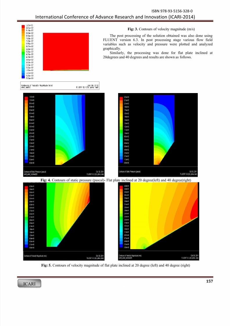
Fig: 3. Contours of velocity magnitude (m/s)
The post processing of the solution obtained was also done usingFLUENT version 6.3. In post processing stage various flow fieldvariables such as velocity and pressure were plotted and analyzedgraphically.
Similarly, the processing was done for flat plate inclined at
20degrees and 40 degrees and results are shown as follows.
Fig: 4. Contours of static pressure (pascal)- Flat plate inclined at 20 degree(left) and 40 degree(right)
Fig: 5. Contours of velocity magnitude of flat plate inclined at 20 degree (left) and 40 degree (right)

8/19/2019 drag effects on flat plate
http://slidepdf.com/reader/full/drag-effects-on-flat-plate 4/4
ISBN 978-93-5156-328-0 International Conference of Advance Research and Innovation (ICARI-2014)
158ICARI
6. Results
Following results were obtained from the FLUENT 1. Flat Plate parallel to flow stream.
Table: 1. Results for plate parallel to flow direction
DragForce,Fd
LiftForce,Fl
Coefficient ofdrag, C d
Coefficient oflift, C l
Laminar flow
0.0005 N
0 0.43 0
2. Plate inclined at 20 0 to horizontal
Table: 2. Results for plate inclined at 20 0 to horizontal
DragForce, F d
LiftForce,Fl
Coefficient of drag,Cd
Coefficient oflift, C l
Laminar flow
0.65N 50.63 N
0.0013 0.048
3. Plate inclined at 40 0 to horizontal
Table: 3. Results for plate inclined at 40 0 to horizontal
DragForce,Fd
LiftForce,Fl
Coefficientof drag, C d
Coefficient oflift, C l
Laminarflow
0.07N 284N 0.0006 1.288
4. Plate inclined at 60 0 to horizontalTable: 4. Results for plate inclined at 60 0 to horizontal
DragForce, F d
LiftForce, F l
Coefficientof drag, C d
Coefficient oflift, C l
Laminar flow
0.33 N
705N 0.0012235385
2.558653
7. Conclusion
After analyzing all the results obtained fromfluent, it was concluded that angle of inclination ofthe flat plate have significant effect on the drag forceacting on the flat plate. It was seen that drag forcechanges prominently as we increase the angle ofinclination of the flat plate with the horizontal. It wasalso observed that static pressure acting on the flat
plate changes its value along its length i.e. it is notconstant for overall length of the flat plate. Pressure ismaximum at the leading edge of the flat plate anddecreases gradually along the length of the flat plate.An opposite pattern was observed in case of velocityof air along the flat plate. Velocity has minimumvalue at the leading edge of the plate and increasesalong the length of the flat plate and reaches itsmaximum value at the trailing edge of the flat plate.
References
[1] Quanhua Sun, Iain D. Boyd, “University ofMichigan, Ann Arbor, Michigan”, Drag on a FlatPlate in Low-Reynolds-Number Gas Flows
[2] Kunihiko Taira, William B. Dickson, TimColonius§, Michael H. Dickinson CaliforniaInstitute of Technology, Pasadena, California,Clarence W. RowleykPrinceton University,Princeton, New Jersey “Unsteadiness in Flowover a Flat Plate atAngle-of-Attack at LowReynolds Number”
[3] Edwin J. Saltzman, Robert R. Meyer “Dragreduction obtained by rounding the verticalcorners on a box shaped ground vehicle”
[4] N. K. Chougule, G. V. Parishwad, P. R. Gore,Pagnis S., Sapali S.N . “CFD Analysis of Multi-
jet Air Impingement on Flat Plate”[5] Y. Maghmoumi1, M. A. Alavi, M. R. Safaiy, I.
Norollahi, “Numerical Analyses of Steady Non- Newtonian Flow over Flat Plate on IntermediateReynolds Numbers by Finite Volume Method”
[6] Ronald E. Hanson_, Howard P. Buckley, PhilippeLavoie, “Aerodynamic Optimization of the Flat
Plate Leading Edge for Experimental Studies ofLaminar and Transitional Boundary Layers”
[7] Cingel, Cimbala “Introduction to fluid dynamics”[8] J. D.Anderson “Computaional Fluid Dynamics”[9] Fox and Mcdonalds “Computaional Fluid
Dynamics” INTERNET[10] “Aerodynamics”
http://en.wikipedia.org/wiki/Aerodynamics[11] “Computaional Fluid Dynamics”-
http://en.wikipedia.org/wiki/Computational_fluid _dynamics
[12] “Fluent Learning Modules”https://confluence.cornell.edu/display/SIMULAT
ION/FLUENT+Learning+Modules[13] “Gambit 2.2 tutorial guide” http://vincent.chapin.
free.fr/Cours%20CFD/Doc/gambit-2.2 tutorials. pdf
[14] “Fluent 6.3 tutotrial guide” http://hpce.iitm.ac.in/website//Manuals/Fluent_6.3/fluent6.3/help/pdf/tg/pdf.htm