draka offshore cables - electrical cable supply power and...draka offshore cables sddr code: g06...
TRANSCRIPT


Draka Offshore Cables
SDDR code: G06
Doc. title: Technical Data Book Doc. no.:
Page 2 of 33 Rev. 00
T E C H N I C A L D A T A for
Electrical, Instrumentation and Communication
Offshore Cables
LIST OF CONTENT: RFXU 0,6/1KV, BLACK SHEATH, UNARMOURED ............................................................................................................4
CONSTRUCTION.......................................................................................................................................................................4 RANGE AND DIMENSIONS RFXU 0,6/1kV ........................................................................................................................5 ELECTRICAL DATA ..................................................................................................................................................................5 INSTALLATION DATA...............................................................................................................................................................5
RFOU 0,6/1KV, BLACK, ARMOURED, FLAME RETARDANT .........................................................................................6 CONSTRUCTION.......................................................................................................................................................................6 RANGE AND DIMENSIONS RFOU 0,6/1kV........................................................................................................................7 ELECTRICAL DATA ..................................................................................................................................................................7 INSTALLATION DATA...............................................................................................................................................................8
BFOU 0,6/1KV, BLACK, ARMOURED, FIRE RESISTANT.................................................................................................9 CONSTRUCTION.......................................................................................................................................................................9 RANGE AND DIMENSIONS BFOU 0,6/1 kV......................................................................................................................10 ELECTRICAL DATA ................................................................................................................................................................10 INSTALLATION DATA.............................................................................................................................................................11
UX 600V, YELLOW/GREEN, TYPE G...................................................................................................................................12 CONSTRUCTION.....................................................................................................................................................................12 RANGE AND DIMENSIONS UX 600V ..................................................................................................................................13 ELECTRICAL DATA ................................................................................................................................................................13 INSTALLATION DATA.............................................................................................................................................................13

Draka Offshore Cables
SDDR code: G06
Doc. title: Technical Data Book Doc. no.:
Power and Instrumentation Cables
Page 3 of 33 Rev. 00
BFOU (I+C) 250V, GREY (NIS), BLUE (IS), ARMOURED.................................................................................................14
CONSTRUCTION.....................................................................................................................................................................14 RANGE AND DIMENSIONS BFOU (i+c) 250V, Grey (NIS) ...............................................................................................15 RANGE AND DIMENSIONS BFOU (i+c) 250V, Blue (IS) ..................................................................................................15 ELECTRICAL CHARACTERISTICS ........................................................................................................................................16 INSTALLATION DATA.............................................................................................................................................................16
BFXU (I+C) 250V, GREY (NIS), BLUE (IS), UNARMOURED ...........................................................................................17 CONSTRUCTION.....................................................................................................................................................................17 RANGE AND DIMENSIONS BFXU (i+c) 250V, Grey (NIS)................................................................................................18 RANGE AND DIMENSIONS BFXU (i+c) 250V, Blue (IS)...................................................................................................18 ELECTRICAL CHARACTERISTICS ........................................................................................................................................18 INSTALLATION DATA.............................................................................................................................................................19
QFCI OPTICAL FIBER CABLE, ORANGE SHEATH, ITEM 27 ......................................................................................20
BOSTRIG MHV SINGLE CONDUCTOR CABLE, ITEM 40, 41,42...................................................................................22
BOSTRIG MHV THREE CONDUCTOR CABLE, ITEM 43...............................................................................................23
CONDUCTOR BUILT-UP AND RESISTANCE, IEC 60228................................................................................................24
TESTS METHODS FOR ALL CABLE COMPONENTS IN THE RFOU, RFXU, BFOU AND BFXU CABLES..........25
INSTALLATION RECOMMENDATIONS............................................................................................................................26
STANDARD WOODEN DRUM...............................................................................................................................................27
STANDARD WOODEN DRUM...............................................................................................................................................27
STANDARD WOODEN DRUM, PACKED, WITH LAGGING...........................................................................................28
PREPARATION FOR SHIPMENT .........................................................................................................................................29
UNPACKING PROCEDURE ...................................................................................................................................................29
SHIPPING AND STORAGE RECOMMENDATIONS.........................................................................................................29
HANDLING OF CABLE DRUMS ...........................................................................................................................................30 Tightening.................................................................................................................................................................................30 Rolling of drums .......................................................................................................................................................................30 Lifting .......................................................................................................................................................................................30 Stacking ....................................................................................................................................................................................31 Inner Cable End .......................................................................................................................................................................31 Temperature .............................................................................................................................................................................31 Direction of spooling ................................................................................................................................................................32 Cutting ......................................................................................................................................................................................32 Transport - road/rail ................................................................................................................................................................32
CODE DESIGNATION .............................................................................................................................................................33
Draka Offshore Cables
SDDR code: G06
Doc. title: Technical Data Book Doc. no.:
Power and Instrumentation Cables
Page 4 of 33 Rev. 00
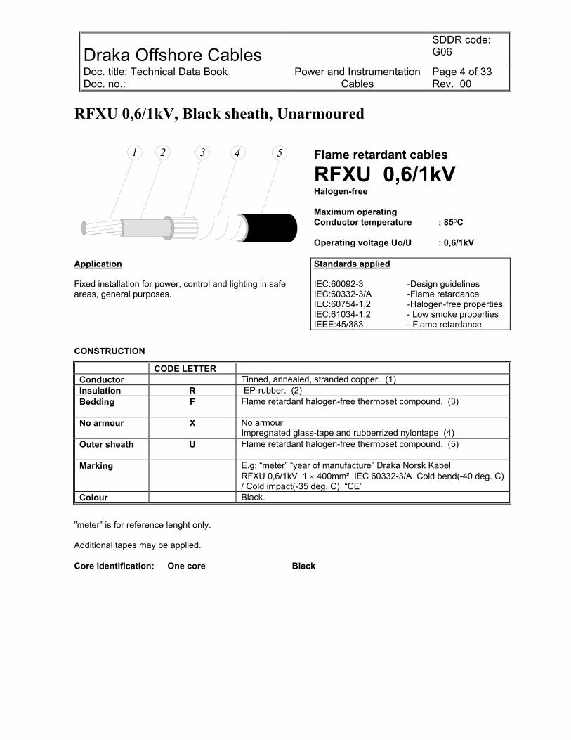
RFXU 0,6/1kV, Black sheath, Unarmoured
Flame retardant cables
RFXU 0,6/1kV Halogen-free Maximum operating Conductor temperature : 85OC Operating voltage Uo/U : 0,6/1kV
Application Fixed installation for power, control and lighting in safe areas, general purposes.
Standards applied IEC:60092-3 -Design guidelines IEC:60332-3/A -Flame retardance IEC:60754-1,2 -Halogen-free properties IEC:61034-1,2 - Low smoke properties IEEE:45/383 - Flame retardance
CONSTRUCTION
CODE LETTER Conductor Tinned, annealed, stranded copper. (1) Insulation R EP-rubber. (2) Bedding
F Flame retardant halogen-free thermoset compound. (3)
No armour
X No armour Impregnated glass-tape and rubberrized nylontape (4)
Outer sheath U
Flame retardant halogen-free thermoset compound. (5)
Marking E.g; “meter” “year of manufacture” Draka Norsk Kabel RFXU 0,6/1kV 1 × 400mm² IEC 60332-3/A Cold bend(-40 deg. C) / Cold impact(-35 deg. C) “CE”
Colour Black.
”meter” is for reference lenght only. Additional tapes may be applied. Core identification: One core Black
1 2 3 4 5
Draka Offshore Cables
SDDR code: G06
Doc. title: Technical Data Book Doc. no.:
Power and Instrumentation Cables
Page 5 of 33 Rev. 00
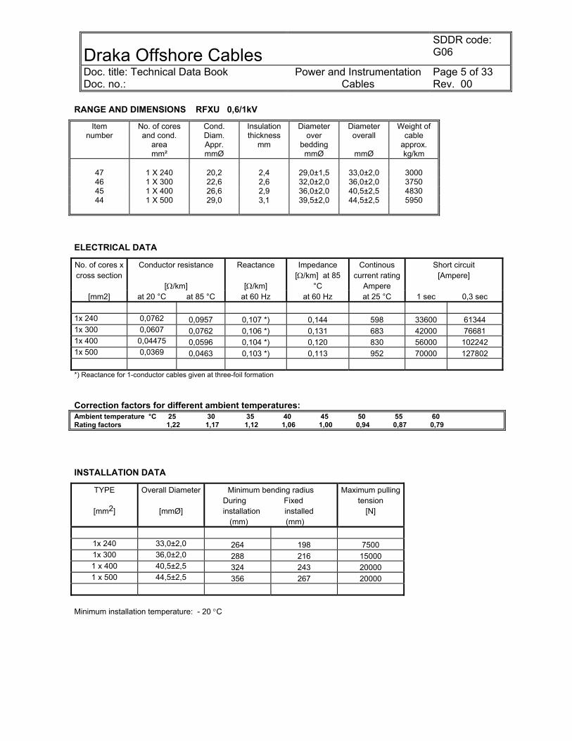
RANGE AND DIMENSIONS RFXU 0,6/1kV
Item number
No. of cores and cond.
area mm²
Cond. Diam. Appr. mmØ
Insulation thickness
mm
Diameter over
bedding mmØ
Diameter overall
mmØ
Weight of cable
approx. kg/km
47 1 X 240 20,2 2,4 29,0±1,5 33,0±2,0 3000 46 1 X 300 22,6 2,6 32,0±2,0 36,0±2,0 3750 45 1 X 400 26,6 2,9 36,0±2,0 40,5±2,5 4830 44 1 X 500 29,0 3,1 39,5±2,0 44,5±2,5 5950
ELECTRICAL DATA
No. of cores x cross section
Conductor resistance
[Ω/km]
Reactance
[Ω/km]
Impedance [Ω/km] at 85
°C
Continous current rating
Ampere
Short circuit [Ampere]
[mm2] at 20 °C at 85 °C at 60 Hz at 60 Hz at 25 °C 1 sec 0,3 sec 1x 240 0,0762 0,0957 0,107 *) 0,144 598 33600 61344 1x 300 0,0607 0,0762 0,106 *) 0,131 683 42000 76681 1x 400 0,04475 0,0596 0,104 *) 0,120 830 56000 102242 1x 500 0,0369 0,0463 0,103 *) 0,113 952 70000 127802 *) Reactance for 1-conductor cables given at three-foil formation Correction factors for different ambient temperatures: Ambient temperature °C 25 30 35 40 45 50 55 60 Rating factors 1,22 1,17 1,12 1,06 1,00 0,94 0,87 0,79
INSTALLATION DATA
TYPE
[mm2]
Overall Diameter
[mmØ]
Minimum bending radius During Fixed installation installed (mm) (mm)
Maximum pulling tension
[N]
1x 240 33,0±2,0 264 198 7500 1x 300 36,0±2,0 288 216 15000 1 x 400 40,5±2,5 324 243 20000 1 x 500 44,5±2,5 356 267 20000
Minimum installation temperature: - 20 °C

Draka Offshore Cables SDDR code: G06
Doc. title: Technical Data Book Doc. no.:
Power and Instrumentation Cables
Page 6 of 33 Rev. 00
RFOU 0,6/1kV, Black, Armoured, Flame retardant
1 2 3 4 5 6 7
Flame retardant cables
RFOU 0,6/1kV Halogen-free Maximum operating Conductor temperature : 85OC Operating voltage Uo/U : 0,6/1kV
Application Fixed installation for power, control and lighting in both EX- and safe areas, general purposes.
Standards applied IEC:60092-3 - Design guidelines IEC:60332-3/A - Flame retardance IEC:60754-1,2 - Halogen-free propertiesIEC:61034-1,2 - Low smoke properties IEEE:45/383 - Flame retardance
CONSTRUCTION
CODE LETTER Conductor Tinned, annealed, stranded copper. (1)
Insulation
R EP-rubber. (2)
Bedding
F Flame retardant halogen-free thermoset compound. (3) PETP-tape (4)
Armour
O Tinned copper wire braid. (5) PETP-tape and rubberized nylon-tape. (6)
Outer sheath U Flame retardant halogen-free thermoset compound. (7)
Marking (example)
“meter” “year of manufacture” DRAKA NORSK KABEL RFOU 0,6/1kV 3 × 4mm² FLEX-FLAME IEC 60332-3/A Cold bend(-40 deg. C) / Cold impact(-35 deg. C) “CE”
Colour Black. “meter” is for reference length only. Core identification: One core Black Two cores Black - Offwhite Three cores Black - Red – Blue Four cores Black - Red – Blue - Offwhite Five cores and above Black number on Offwhite base Neutral Offwhite

Draka Offshore Cables
SDDR code: G06
Doc. title: Technical Data Book Doc. no.:
Power and Instrumentation Cables
Page 7 of 33 Rev. 00
RANGE AND DIMENSIONS RFOU 0,6/1kV
Item number
No. of cores and cond.
area mm²
Cond. Diam. Appr. mmØ
Insulation thickness
mm
Diameter over
bedding mmØ
Diameter overall
mmØ
Weight of cable
approx. kg/km
64 2 X 4/6 2,6 1,1 12,0±1,0 16,0±1,0 410
65 3 X 2,5/6 2,0 1,0 11,5±1,0 15,0±1,0 360 63 3 X 4/6 2,6 1,1 13,0±1,0 17,0±1,0 470 61 3 X 6/6 3,2 1,1 14,5±1,0 18,5±1,0 590 60 3 X 10/10 4,1 1,2 17,0±1,0 21,0±1,5 800 59 3 X 16/16 5,2 1,3 20,0±1,5 24,5±1,5 1210 58 3 X 25/16 6,6 1,4 23,0±1,5 28,0±1,5 1570 57 3 X 50/25 9,1 1,6 30,0±2,0 36,0±2,0 2740 55 3 X 70/35 10,7 1,7 35,0±2,0 41,0±2,5 3740 54 3 X 95/50 12,6 1,9 39,5±2,0 46,5±2,5 4970
51, 52 3 X 120/60 14,2 2,0 44,0±2,5 51,0±3,0 6180 50 3 x 150/70 * 15,9 2,1 48,0±2,5 57,5±3,0 7350 49 3 X 185 ** 48 3 X 300 ***
62 4 X 4/6 2,6 1,1 14,5±1,0 18,5±1,0 575 58 4 X 50/25 9,1 1,6 33,0±2,0 39,0±2,0 3390 53 4 X 95/50 12,6 1,9 44,0±2,5 51,0±3,0 6100
*) This cable has a double braid (two layers of copper braids) **) Instead of the 3 core 185 mm² we offer a parallell connection with 2 cables 3 core 70/35 mm² (as item 55) **) Instead of the 3 core 300 mm² we offer a parallell connection with 2 cables 3 core 95/50 mm² (as item 54)
ELECTRICAL DATA
No. of cores x cross section
Conductor resistance
[Ω/km]
Reactance
[Ω/km]
Impedance [Ω/km] at 85
°C
Continous current rating
Ampere
Short circuit [Ampere]
[mm2] at 20 °C at 85 °C at 60 Hz at 60 Hz at 25 °C 1 sec 0,3 sec 2x 4/6 4,70 5,90 0,118 5,902 39 560 1022 3x 2,5/6 7,56 9,49 0,123 9,492 24 350 639 3x 4/6 4,70 5,90 0,118 5,902 33 560 1022 3x 6/6 3,11 3,91 0,111 3,906 41 840 1534 3x 10/10 1,84 2,31 0,106 2,312 57 1400 2556 3x 16/16 1,16 1,46 0,102 1,460 77 2240 4089 3x 25/16 0,734 0,921 0,098 0,927 102 3500 6390 3x 50/25 0,391 0,491 0,094 0,500 152 7000 12780 3x 70/35 0,270 0,339 0,092 0,351 195 9800 17892 3x 95/50 0,195 0,245 0,091 0,261 238 13300 24282 3x 120/60 0,154 0,193 0,090 0,213 275 16800 30672 3x 150/70 0,126 0,158 0,089 0,181 311 21000 38340 4x 4/6 4,70 5,90 0,118 5,902 33 560 1022 4x 50/25 0,391 0,491 0,094 0,500 152 7000 12780 4x 95/50 0,195 0,245 0,091 0,261 238 13300 24282

Draka Offshore Cables
SDDR code: G06
Doc. title: Technical Data Book Doc. no.:
Power and Instrumentation Cables
Page 8 of 33 Rev. 00
Correction factors for different ambient temperatures: Ambient temperature °C 25 30 35 40 45 50 55 60 Rating factors 1,22 1,17 1,12 1,06 1,00 0,94 0,87 0,79
INSTALLATION DATA
TYPE
[mm2]
Overall Diameter
[mmØ]
Minimum bending radius During Fixed installation installed (mm) (mm)
Maximum pulling tension
[N]
2x 4/6 16,0±1,0 128 96 400 3x 2,5/6 15,0±1,0 120 90 375 3x 4/6 17,0±1,0 136 102 600 3x 6/6 18,5±1,0 148 111 900 3x 10/10 21,0±1,5 168 126 1500 3x 16/16 24,5±1,5 196 147 2400 3x 25/16 28,0±1,5 224 168 3750 3x 50/25 36,0±2,0 288 216 7500 3x 70/35 41,0±2,5 328 246 10500 3x 95/50 46,5±2,5 372 279 14250 3x 120/60 51,0±3,0 408 306 18000 3x 150/70 57,5±3,0 460 345 20000 4x 4/6 18,5±1,0 148 111 800 4x 50/25 39,0±2,0 312 234 10000 4x 95/50 51,0±3,0 408 309 19000 Minimum installation temperature: - 20 °C

Draka Offshore Cables
SDDR code: G06
Doc. title: Technical Data Book Doc. no.:
Power and Instrumentation Cables
Page 9 of 33 Rev. 00
BFOU 0,6/1kV, Black, Armoured, Fire resistant
1 2 3 4 5 6 7 8
Fire resistant cables
BFOU 0,6/1kV Halogen free Maximum operating Conductor temperature : 85OC Operating voltage Uo/U : 0,6/1kV
Application Fixed installation for power,control and lighting in both EX- and safe areas, emergency and critical systems.
Standards applied IEC:60092-3 - Design guidelines IEC:60332-3/A - Flame retardance IEC:60754-1,2 - Halogen-free propertiesIEC:61034-1,2 - Lowskome properties IEC:60331 - Fire resistance IEEE:45/383 - Flame retardance
CONSTRUCTION
CODE LETTER Conductor Tinned, annealed, stranded copper. (1)
Insulation
B Mica-tape (2) / EP-rubber. (3)
Bedding F Flame retardant halogen-free thermoplastic compound. (4) PETP-tape (5)
Armour O Tinned copper wire braid. (6) PETP-tape and rubberized nylon-tape (7)
Outer sheath U
Flame retardant halogen-free thermoset compound. (8)
Marking (example)
E.g; “meter” “year of manufacture” DRAKA NORSK KABEL BFOU 0,6/1kV 3 × 2,5/6mm² IEC 60331 IEC 60332-3/A Cold bend(-40 deg. C) / Cold impact(-35 deg. C) “CE”
Colour Black. “meter” is for reference length only. Core identification: Three cores Black – Red – Blue Four cores Black – Red – Blue - Offwhite 5 cores and above Black numbers on Offwhite base Neutral Offwhite
Draka Offshore Cables
SDDR code: G06
Doc. title: Technical Data Book Doc. no.:
Power and Instrumentation Cables
Page 10 of 33 Rev. 00
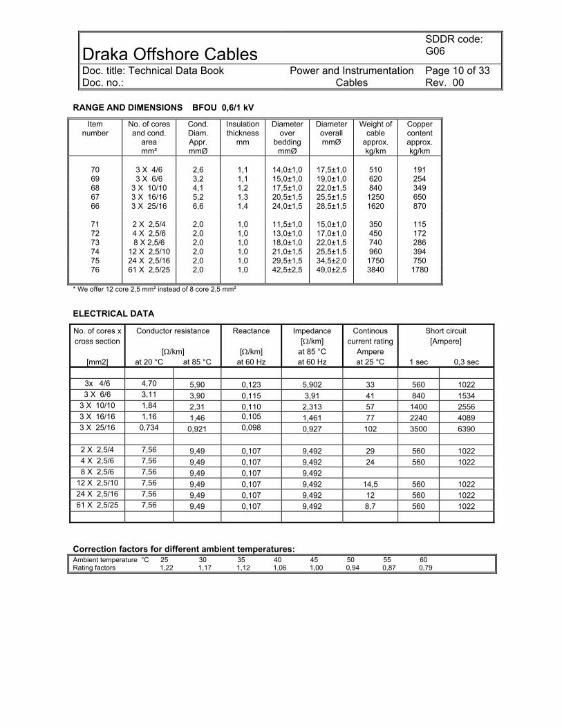
RANGE AND DIMENSIONS BFOU 0,6/1 kV
Item number
No. of cores and cond.
area mm²
Cond. Diam. Appr. mmØ
Insulation thickness
mm
Diameter over
bedding mmØ
Diameter overall mmØ
Weight of cable
approx. kg/km
Copper content approx. kg/km
70 3 X 4/6 2,6 1,1 14,0±1,0 17,5±1,0 510 191 69 3 X 6/6 3,2 1,1 15,0±1,0 19,0±1,0 620 254 68 3 X 10/10 4,1 1,2 17,5±1,0 22,0±1,5 840 349 67 3 X 16/16 5,2 1,3 20,5±1,5 25,5±1,5 1250 650 66 3 X 25/16 6,6 1,4 24,0±1,5 28,5±1,5 1620 870
71 2 X 2,5/4 2,0 1,0 11,5±1,0 15,0±1,0 350 115 72 4 X 2,5/6 2,0 1,0 13,0±1,0 17,0±1,0 450 172 73 8 X 2,5/6 2,0 1,0 18,0±1,0 22,0±1,5 740 286 74 12 X 2,5/10 2,0 1,0 21,0±1,5 25,5±1,5 960 394 75 24 X 2,5/16 2,0 1,0 29,5±1,5 34,5±2,0 1750 750 76 61 X 2,5/25 2,0 1,0 42,5±2,5 49,0±2,5 3840 1780
* We offer 12 core 2,5 mm² instead of 8 core 2,5 mm²
ELECTRICAL DATA
No. of cores x cross section
Conductor resistance
[Ω/km]
Reactance
[Ω/km]
Impedance [Ω/km]
at 85 °C
Continous current rating
Ampere
Short circuit [Ampere]
[mm2] at 20 °C at 85 °C at 60 Hz at 60 Hz at 25 °C 1 sec 0,3 sec
3x 4/6 4,70 5,90 0,123 5,902 33 560 1022 3 X 6/6 3,11 3,90 0,115 3,91 41 840 1534
3 X 10/10 1,84 2,31 0,110 2,313 57 1400 2556 3 X 16/16 1,16 1,46 0,105 1,461 77 2240 4089 3 X 25/16 0,734 0,921 0,098 0,927 102 3500 6390
2 X 2,5/4 7,56 9,49 0,107 9,492 29 560 1022 4 X 2,5/6 7,56 9,49 0,107 9,492 24 560 1022 8 X 2,5/6 7,56 9,49 0,107 9,492
12 X 2,5/10 7,56 9,49 0,107 9,492 14,5 560 1022 24 X 2,5/16 7,56 9,49 0,107 9,492 12 560 1022 61 X 2,5/25 7,56 9,49 0,107 9,492 8,7 560 1022
Correction factors for different ambient temperatures: Ambient temperature °C 25 30 35 40 45 50 55 60 Rating factors 1,22 1,17 1,12 1,06 1,00 0,94 0,87 0,79
Draka Offshore Cables
SDDR code: G06
Doc. title: Technical Data Book Doc. no.:
Power and Instrumentation Cables
Page 11 of 33 Rev. 00
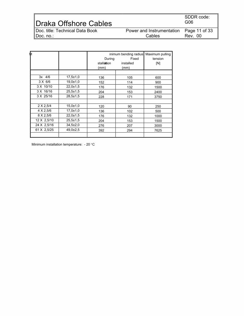
M inimum bending radius During Fixed installation installed
(mm) (mm)
Maximum pulling tension
[N]
3x 4/6 17,5±1,0 136 105 600 3 X 6/6 19,0±1,0 152 114 900
3 X 10/10 22,0±1,5 176 132 1500 3 X 16/16 25,5±1,5 204 153 2400 3 X 25/16 28,5±1,5 228 171 3750
2 X 2,5/4 15,0±1,0 120 90 250 4 X 2,5/6 17,0±1,0 136 102 500 8 X 2,5/6 22,0±1,5 176 132 1000
12 X 2,5/10 25,5±1,5 204 153 1500 24 X 2,5/16 34,5±2,0 276 207 3000 61 X 2,5/25 49,0±2,5 392 294 7625
Minimum installation temperature: - 20 °C

Draka Offshore Cables
SDDR code: G06
Doc. title: Technical Data Book Doc. no.:
Power and Instrumentation Cables
Page 12 of 33 Rev. 00
UX 600V, Yellow/Green, Type G
1 2 3
Flame retardant conductors
UX 600V Halogen-free Maximum operating conductor temperature : 85OC Operating voltage Uo/U : 600V
Application Insulated conductor for earthing and bonding services.
Standards applied IEC:60092-3 - Design guidelines IEC:60332-1 - Flame retardance IEC:60332-3/A - Flame retardance IEC:60754-1,2 - Halogen-free propertiesIEC:61034-1,2 - Low smoke properties IEEE: 45/383 - Flame retardance
CONSTRUCTION
CODE LETTER Conductor Tinned, annealed, stranded copper. (1)
Rubberized nylon-tape (2)
Insulation
U Flame retardant halogen-free thermoset compound. (3)
Unsheathed X
Marking Example
“meter” “year of manufacture” DRAKA NORSK KABEL UX 600V 1 x 70 mm² FLEX-FLAME IEC 60332-3/A Cold bend(-40 deg. C) / Cold impact(-35 deg. C) “CE”
Colour Yellow/Green
“meter” is for reference length only.

Draka Offshore Cables
SDDR code: G06
Doc. title: Technical Data Book Doc. no.:
Power and Instrumentation Cables
Page 13 of 33 Rev. 00
RANGE AND DIMENSIONS UX 600V
Item number
No. of cores and cond. area
mm²
Cond. Diam.
Appr. mmØ
Insulation thickness
mm
Diameter overall
mmØ
Weight of cable approx. kg/km
Copper content
approx. kg/km
77 1 x 6 3,2 1,1 6,0±0,8 85 54 78 1 x 16 5,2 1,3 8,5±0,8 190 143 79 1 x 35 7,7 1,5 11,5±1,0 390 310 80 1 x 70 10,9 1,7 15,0±1,0 740 620
ELECTRICAL DATA
No. of cores x cross section
Conductor resistance [Ω/km]
Reactance [Ω/km]
Impedance [Ω/km] at 85
°C
Continous current rating
Short circuit [Ampere]
[mm2] at 20 °C at 85 °C at 60 Hz at 60 Hz at 25 °C 1 sec 0,3 sec
1 x 6 3,11 3,91 N/A N/A 59 840 1534 1 x 16 1,16 1,46 N/A N/A 110 2240 4089 1 x 35 0,529 0,664 N/A N/A 177 4900 8946 1 x 70 0,270 0,339 N/A N/A 275 9800 17982
N/A = not applicable Correction factors for different ambient temperatures: Ambient temperature °C 25 30 35 40 45 50 55 60 Rating factors 1,22 1,17 1,12 1,06 1,00 0,94 0,87 0,79
INSTALLATION DATA
TYPE
[mm2]
Overall Diameter
[mmØ]
Minimum bending radius During Fixed installation installed (mm) (mm)
Maximum pulling tension
[N]
1 x 6 6,0±0,8 48 36 300 1 x 16 8,5±0,8 68 51 800 1 x 35 11,5±1,0 92 69 1750 1 x 70 15,0±1,0 120 90 3500
Minimum installation temperature: - 20 °C
Draka Offshore Cables
SDDR code: G06
Doc. title: Technical Data Book Doc. no.:
Power and Instrumentation Cables
Page 14 of 33 Rev. 00
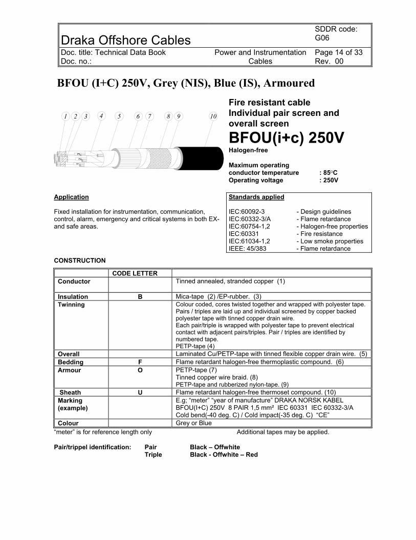
BFOU (I+C) 250V, Grey (NIS), Blue (IS), Armoured
54
31
2
76 91 2 3 4 5 8 10
Fire resistant cable Individual pair screen and overall screen
BFOU(i+c) 250V Halogen-free Maximum operating conductor temperature : 85OC Operating voltage : 250V
Application Fixed installation for instrumentation, communication, control, alarm, emergency and critical systems in both EX- and safe areas.
Standards applied IEC:60092-3 - Design guidelines IEC:60332-3/A - Flame retardance IEC:60754-1,2 - Halogen-free propertiesIEC:60331 - Fire resistance IEC:61034-1,2 - Low smoke properties IEEE: 45/383 - Flame retardance
CONSTRUCTION
CODE LETTER Conductor Tinned annealed, stranded copper (1)
Insulation B Mica-tape (2) /EP-rubber. (3) Twinning Colour coded, cores twisted together and wrapped with polyester tape.
Pairs / triples are laid up and individual screened by copper backed polyester tape with tinned copper drain wire. Each pair/triple is wrapped with polyester tape to prevent electrical contact with adjacent pairs/triples. Pair / triples are identified by numbered tape. PETP-tape (4)
Overall Laminated Cu/PETP-tape with tinned flexible copper drain wire. (5) Bedding F Flame retardant halogen-free thermoplastic compound. (6) Armour O PETP-tape (7)
Tinned copper wire braid. (8) PETP-tape and rubberized nylon-tape. (9)
Sheath U Flame retardant halogen-free thermoset compound. (10) Marking (example)
E.g; “meter” “year of manufacture” DRAKA NORSK KABEL BFOU(I+C) 250V 8 PAIR 1,5 mm² IEC 60331 IEC 60332-3/A Cold bend(-40 deg. C) / Cold impact(-35 deg. C) “CE”
Colour Grey or Blue “meter” is for reference length only Additional tapes may be applied. Pair/trippel identification: Pair Black – Offwhite Triple Black - Offwhite – Red

Draka Offshore Cables
SDDR code: G06
Doc. title: Technical Data Book Doc. no.:
Power and Instrumentation Cables
Page 15 of 33 Rev. 00
RANGE AND DIMENSIONS BFOU (i+c) 250V, Grey (NIS) Item
number
No. of pairs and
conductor area mm²
Cond. Diam. approx
mmØ
Insulation thickness
mmØ
Bedding thickness
mm
Diameter over
bedding
mmØ
Armour wire
thickness
mmØ
Outer sheath
thickness
mm
Diameter overall
mmØ
Weight of
cable Approx kg/km
Copper content approx
kg/km
2 4 pair 0,75 1,1 0,8 1,2 14,5±1,0 0,25 1,4 19,0±1,0 535 175
4 1 pair 1,0 1,3 0,8 1,1 9,0±0,8 0,20 1,1 12,5±1,0 235 72 6 4 pair 1,0 1,3 0,8 1,2 16,0±1,0 0,25 1,5 20,5±1,5 625 220
8 1 pair 1,5 1,6 0,8 1,1 9,5±0,8 0,20 1,2 13,0±1,0 275 95 12 2 pair 1,5 1,6 0,8 1,2 15,0±1,0 0,25 1,4 19,0±1,0 545 190 14 4 pair 1,5 1,6 0,8 1,3 17,5±1,0 0,25 1,5 22,0±1,5 750 296 16 12 pair 1,5 1,6 0,8 1,5 28,0±1,5 0,30 1,9 33,0±2,0 1710 720 18 24 pair 1,5 1,6 0,8 1,7 38,5±2,0 0,40 2,3 44,5±2,5 3190 1390
10 1 pair 2,5 2,0 0,8 1,1 10,5±1,0 0,20 1,2 14,0±1,0 330 120
20 1 triple 1,5 1,6 0,8 1,1 10,5±1,0 0,20 1,2 14,0±1,0 310 110 22 2 triple 1,5 1,6 0,8 1,2 16,5±1,0 0,25 1,5 20,5±1,5 640 230 24 7 triple 1,5 1,6 0,8 1,4 23,0±1,5 0,30 1,8 28,0±1,5 1365 580 26 12 triple 1,5 1,6 0,8 1,5 31,0±2,0 0,30 2,0 36,0±2,0 2130 910
The coverage density of the braided armour are minimum 90% in acc. with IEC 60092-3
RANGE AND DIMENSIONS BFOU (i+c) 250V, Blue (IS) Item
number
No. of pairs and
conductor area mm²
Cond. Diam. approx
mmØ
Insulation thickness
mmØ
Bedding thickness
Mm
Diameter over
bedding
mmØ
Armour wire
thickness
mmØ
Outer sheath
thickness
mm
Diameter overall
mmØ
Weight of
cable Approx kg/km
Copper content approx kg/km
1 4 pair 0,75 1,1 0,8 1,2 14,5±1,0 0,25 1,4 19,0±1,0 535 175
3 1 pair 1,0 1,3 0,8 1,1 9,0±0,8 0,20 1,1 12,5±1,0 235 72 5 4 pair 1,0 1,3 0,8 1,2 16,0±1,0 0,25 1,5 20,5±1,5 625 220
7 1 pair 1,5 1,6 0,8 1,1 9,5±0,8 0,20 1,2 13,0±1,0 275 95 11 2 pair 1,5 1,6 0,8 1,2 15,0±1,0 0,25 1,4 19,0±1,0 545 190 13 4 pair 1,5 1,6 0,8 1,3 17,5±1,0 0,25 1,5 22,0±1,5 750 296 15 12 pair 1,5 1,6 0,8 1,5 28,0±1,5 0,30 1,9 33,0±2,0 1710 720 17 24 pair 1,5 1,6 0,8 1,7 38,5±2,0 0,40 2,3 44,5±2,5 3190 1390
9 1 pair 2,5 2,0 0,8 1,1 10,5±1,0 0,20 1,2 14,0±1,0 330 120
19 1 triple 1,5 1,6 0,8 1,1 10,5±1,0 0,20 1,2 14,0±1,0 310 110 21 2 triple 1,5 1,6 0,8 1,2 16,5±1,0 0,25 1,5 20,5±1,5 640 230 23 7 triple 1,5 1,6 0,8 1,4 23,0±1,5 0,30 1,8 28,0±1,5 1365 580 25 12 triple 1,5 1,6 0,8 1,5 31,0±2,0 0,30 2,0 36,0±2,0 2130 910
The coverage density of the braided armour are minimum 90% in acc. with IEC 60092-3

Draka Offshore Cables
SDDR code: G06
Doc. title: Technical Data Book Doc. no.:
Power and Instrumentation Cables
Page 16 of 33 Rev. 00
ELECTRICAL CHARACTERISTICS
Type Capacitance approx. nF/km
Inductance approx. mH/km
Resistance at 20°C max. Ohm/km
L/R ratio H/ohm
Single pair 0,75 90 0,75 24,8 15,12
Single pair/triple 1,5 110 0,68 12,2 27,87 Single pair 2,5 120 0,70 7,56 46,3
Each individually shielded pair/triple has these characteristics
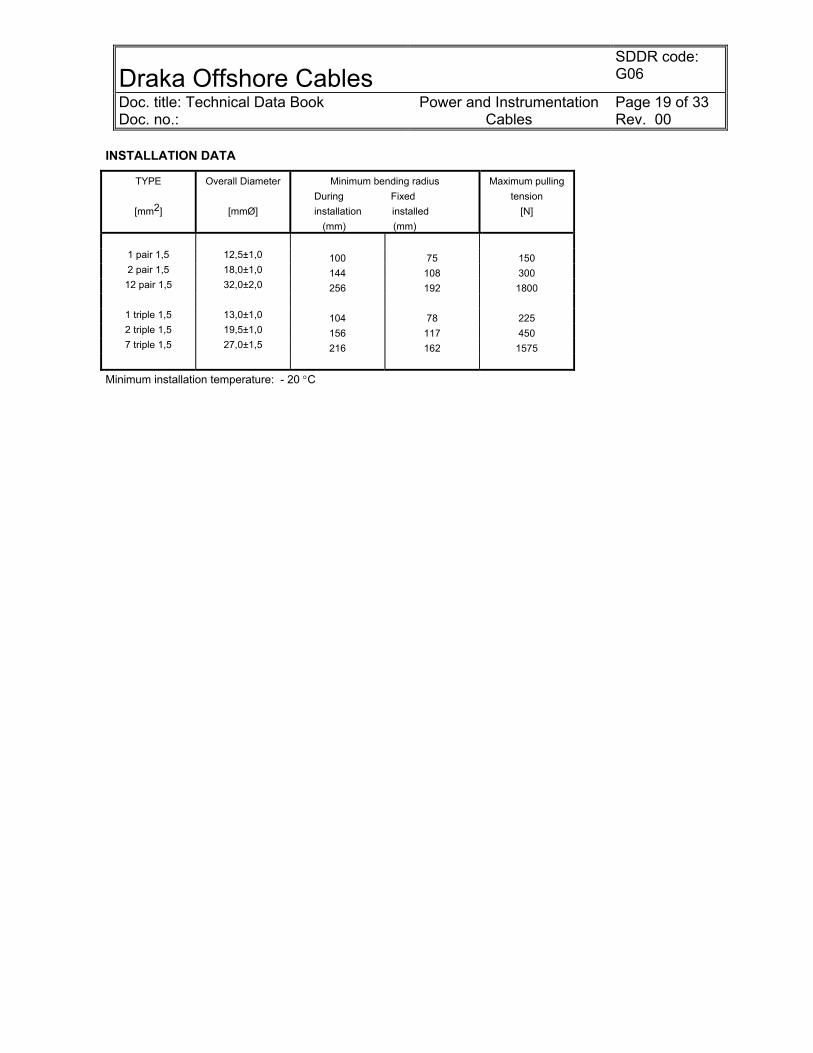
INSTALLATION DATA
TYPE
[mm2]
Overall Diameter
[mmØ]
Minimum bending radius During Fixed installation installed (mm) (mm)
Maximum pulling tension
[N]
4 pair 0,75 19,0±1,0 152 114 300
1 pair 1,0 12,5±1,0 100 75 100 4 pair 1,0 20,5±1,5 164 123 400
1 pair 1,5 13,0±1,0 104 78 150 2 pair 1,5 19,0±1,0 152 114 300 4 pair 1,5 22,0±1,5 176 132 600
12 pair 1,5 33,0±2,0 264 198 1800 24 pair 1,5 44,5±2,5 356 267 3600
1 pair 2,5 14,0±1,0 112 84 250
1 triple 1,5 14,0±1,0 112 84 225 2 triple 1,5 20,5±1,5 164 123 450 7 triple 1,5 28,0±1,5 224 168 1575
12 triple 1,5 36,0±2,0 288 216 2700
Minimum installation temperature: - 20 °C

Draka Offshore Cables
SDDR code: G06
Doc. title: Technical Data Book Doc. no.:
Power and Instrumentation Cables
Page 17 of 33 Rev. 00
BFXU (I+C) 250V, Grey (NIS), Blue (IS), Unarmoured
Fire resistant cable Individual pair screen and overall screen
BFXU(i+c) 250V Halogen-free Maximum operating conductor temperature : 85OC Operating voltage : 250V
Application Fixed installation for instrumentation, communication, control, alarm, emergency and critical systems in both EX- and safe areas.
Standards applied IEC:60092-3 - Design guidelines IEC:60332-3/A - Flame retardance IEC:60754-1,2 - Halogen-free propertiesIEC:60331 - Fire resistance IEC:61034-1,2 - Low smoke properties IEEE: 45/383 - Flame retardance
CONSTRUCTION
CODE LETTER Conductor Tinned annealed, stranded copper (1)
Insulation B Mica-tape (2) /EP-rubber. (3) Twinning Colour coded, cores twisted together and wrapped with polyester tape.
Pairs / triples are laid up and individual screened by copper backed polyester tape with tinned copper drain wire. Each pair/triple is wrapped with polyester tape to prevent electrical contact with adjacent pairs/triples. Pair / triples are identified by numbered tape. PETP-tape (4)
Overall Laminated Cu/PETP-tape with tinned flexible copper drain wire. (5)
Bedding F Flame retardant halogen-free thermoplastic compound. (6)
No Armour X Impregnated glass-tape and rubberized nylon-tape. (7)
Sheath U Flame retardant halogen-free thermoset compound. (9)
Marking (example)
E.g; “meter” “year of manufacture” DRAKA NORSK KABEL BFXU(I+C) 250V 8 PAIR 1,5 mm² IEC 60331 IEC 60332-3/A Cold bend(-40 deg. C) / Cold impact(-35 deg. C) “CE”
Colour Grey or Blue “meter” is for reference length only Additional tapes may be applied. Pair/trippel identification: Pair Black – Offwhite Trippel Black - Offwhite – Red
1 2 3 5 6 7 8
54
4

Draka Offshore Cables
SDDR code: G06
Doc. title: Technical Data Book Doc. no.:
Power and Instrumentation Cables
Page 18 of 33 Rev. 00
RANGE AND DIMENSIONS BFXU (i+c) 250V, Grey (NIS) Item
number
No. of pairs and
conductor area mm²
Cond. Diam. approx
mmØ
Insulation thickness
mmØ
Bedding thickness
mm
Diameter over
bedding
mmØ
Outer sheath
thickness
mm
Diameter overall
mmØ
Weight of
cable Approx kg/km
Copper content approx
kg/km
29 1 pair 1,5 1,6 0,8 1,1 9,5±0,8 1,1 12,5±1,0 220 42 31 2 pair 1,5 1,6 0,8 1,2 15,0±1,0 1,4 18,0±1,0 450 96 33 12 pair 1,5 1,6 0,8 1,5 28,0±1,5 1,8 32,0±2,0 1540 513
35 1 triple 1,5 1,6 0,8 1,1 10,5±1,0 1,1 13,0±1,0 250 57 37 2 triple 1,5 1,6 0,8 1,2 16,5±1,0 1,4 19,5±1,0 525 125 39 7 triple 1,5 1,6 0,8 1,4 23,0±1,5 1,7 27,0±1,5 1175 405
The coverage density of the braided armour are minimum 90% in acc. with IEC 60092-3
RANGE AND DIMENSIONS BFXU (i+c) 250V, Blue (IS) Item
number
No. of pairs and
conductor area mm²
Cond. Diam. approx
mmØ
Insulation thickness
mmØ
Bedding thickness
Mm
Diameter over
bedding
mmØ
Outer sheath
thickness
mm
Diameter overall
mmØ
Weight of
cable Approx kg/km
Copper content approx kg/km
28 1 pair 1,5 1,6 0,8 1,1 9,5±0,8 1,1 12,5±1,0 220 42 30 2 pair 1,5 1,6 0,8 1,2 15,0±1,0 1,4 18,0±1,0 450 96 32 12 pair 1,5 1,6 0,8 1,5 28,0±1,5 1,8 32,0±2,0 1540 513
34 1 triple 1,5 1,6 0,8 1,1 10,5±1,0 1,1 13,0±1,0 250 57 36 2 triple 1,5 1,6 0,8 1,2 16,5±1,0 1,4 19,5±1,0 525 125 38 7 triple 1,5 1,6 0,8 1,4 23,0±1,5 1,7 27,0±1,5 1175 405
The coverage density of the braided armour are minimum 90% in acc. with IEC 60092-3
ELECTRICAL CHARACTERISTICS
Type Capacitance approx. nF/km
Inductance approx. mH/km
Resistance at 20°C max. Ohm/km
L/R ratio H/ohm
Single pair/triple 1,5 110 0,68 12,2 27,87
Each individually shielded pair/triple has these characteristics
Draka Offshore Cables
SDDR code: G06
Doc. title: Technical Data Book Doc. no.:
Power and Instrumentation Cables
Page 19 of 33 Rev. 00
INSTALLATION DATA
TYPE
[mm2]
Overall Diameter
[mmØ]
Minimum bending radius During Fixed installation installed (mm) (mm)
Maximum pulling tension
[N]
1 pair 1,5 12,5±1,0 100 75 150 2 pair 1,5 18,0±1,0 144 108 300
12 pair 1,5 32,0±2,0 256 192 1800
1 triple 1,5 13,0±1,0 104 78 225 2 triple 1,5 19,5±1,0 156 117 450 7 triple 1,5 27,0±1,5 216 162 1575
Minimum installation temperature: - 20 °C

Draka Offshore Cables
SDDR code: G06
Doc. title: Technical Data Book Doc. no.:
Power and Instrumentation Cables
Page 20 of 33 Rev. 00
QFCI optical fiber cable, Orange sheath, item 27
Optical cable for indoor and outdoor use in vital communication and emergency systems that need to be operational during fire. The cable has a patented design that ensures operation for more than 3 hours in fires up to 1000ºC. The cable is halogen free and flame retardant to protect against secondary damage to electronic equipment during and after fire. Outer sheath is made from black UV-stabilized and weather resistant material and may be exposed for shorter periods to fluids such as diesel, petrol, glycol, etanol, white spirite and ASTM oil 2. The resistance to these fluids is according to DOD-STD-1678, method 8030.The cable is reinforced with a steel wire braiding. The fibres are protected in jelly filled loose tubes stranded around a central strength member to ensure optimum performance and long life. Each fibre and loose tube is colour coded for easy identification during splicing and termination. The outer sheath is marked to show fibre type and cable type.
Fire resistant cable
QFCI Indoor and outdoor Fire resistant Flame retardant and halogen free Loose tube
Weight and dimensions
Number of fibres
Number of fibres in each
tube
Number of tubes + fillers
Loose tube diameter
(mm)
Outer diameter
(mm)
Weight
(kg/km)
Heat release
(MJ/km)
12 4 3+3 2.2 13.9 244 1324
Other fibre counts are available on request. Cable properties Tensile strength (IEC 60794-1-2E1) Max tensile load during installation Max tensile load during operation
1500 N500 N
Temperature window Operation Installation Storage
-30°C to +60°C-10°C to +60°C-40°C to +70°C
Crush (IEC 60794-1-2E3) 3000 N/10cm Fire and smoke classifications Impact (IEC 60794-1-2E4) 20 impacts, 5J IEC 60331-25(750°C, 3 hours) <1 dB excess lossTorsion (IEC 60794-1-2E7) Cable bending Minimum bending diameter Cable bend (IEC 60794-1-2E11)
±1 turn/1m
250 mm<0.1dB/ ±5 turn
Upgraded IEC 60331-25(1000°C, 3 hours) BP-236 IEC 61034 IEC 60332-3 cat. A and C IEC 60754-1 IEC 60754-2
<1.5 dB excess loss
Fibres in mica wrapped loose tube Steel strength element Wrapping Inner sheath Filler Steel wire braiding Wrapping Outer sheath

Draka Offshore Cables
SDDR code: G06
Doc. title: Technical Data Book Doc. no.:
Power and Instrumentation Cables
Page 21 of 33 Rev. 00
Optical fibres Fibre type
62.5/125 FDDI
Core diameter 62.5 ± 3.0 µmMode field diameter Cladding diameter 125 ± 2.0 µmPrimary coating diameter (nominal)
250 µm
Attenuation 850 nm 1300 nm
1310 nm 1550 nm
≤ 3.2 dB/km ≤ 0.9 dB/km
Bandwidth 850 nm 1300 nm
>200 MHz⋅km>500 MHz⋅km
Dispersion 1285-1330 nm
1550 nm Numerical aperture 0.275 ± 0.015Minimum permanent bending diameter 50 mm

Draka Offshore Cables
SDDR code: G06
Doc. title: Technical Data Book Doc. no.:
Power and Instrumentation Cables
Page 22 of 33 Rev. 00
Bostrig MHV Single conductor cable, item 40, 41,42 Bostrig MHV-15(LS)BS Cables: Single Conductor Power (Type L Jacket & Sheath) 15kV (IEC 8.7/15 kV) Shielded 100% Level – Armored and Sheathed Application: Bostrig MHV-15(LS)BS single conductor 15,000 volt shielded cables are suitable for use in commercial marine applications, MODU’s and platforms where flame retardant cables having excellent physical and electrical properties are required. These cables have excellent resistance to oils, abrasion, petrochemical fluids, moisture and sunlight. Conductor: Soft annealed tinned copper. Stranding shown in the data table in pdf file embedded below. Conductor Shield: Semi-comnducting tape with extruded thermosetting semi-conducting EPR. Insultation: Extruded thermosetting EPR, 90°C-Type E. Thicknesses shown in the data table in the pdf file embedded below. Insulation Shield: Extruded thermosetting semi-conducting XLPO. Metallic Braid Shield: Tinned copper braided shield, 85% coverage. Jacket and Sheath: Both the inner jacket applied over the metallic braid and the outer sheath over the armor is flame retardant, Low Smoke Zero Halogen chemically crosslinked polyolefin (XLPO). Thicknesses shown in the data table in the pdf file embedded below. Armor: Braided Bronze. Tests: Meets applicable test requirements in IEC 60502, IEC 60092-354, IEEE 45-1998 & 1993 (draft), ICEA S-68-516, UL 1072, J-120 and flame test in IEC 332-2, cat A, A/F. Rating: Listed by a Nationally Recognized Testing Laboratory, (NRTL) in conformance to IEC 60502, IEC 60092-354, UL 1072 and ICEA S-68-516. Cable meets the performance requirements of IEEE 45-1998 % 1993 (draft). Type approved by DNV, ABS and LRS. Bostrig MHV-15(LS)BS data sheet: Double Click to Open:
MHV 15kVLS(IEC8,7 15kV).pdf

Draka Offshore Cables
SDDR code: G06
Doc. title: Technical Data Book Doc. no.:
Power and Instrumentation Cables
Page 23 of 33 Rev. 00
Bostrig MHV Three conductor cable, item 43
Bostrig MHV3-15BS(LS) Cables: Three Conductor Power (Type L Jacket & Sheath) 15kV (IEC 8.7/15 kV) Shielded 100% Level – Armored and Sheathed Application: Bostrig MHV3-15(LS)BS single conductor 15,000 volt shielded cables are suitable for use in commercial marine applications, MODU’s and platforms where flame retardant cables having excellent physical and electrical properties are required. These cables have excellent resistance to oils, abrasion, petrochemical fluids, moisture and sunlight. Cables are also available with either a fully insulated grounding conductor or an un-insulated grounding conductor evenly distributed in the interstices of the cable. Conductor: Soft annealed tinned copper. Stranding shown in the data table in pdf file embedded below. Conductor Shield: Semi-comnducting tape with extruded thermosetting semi-conducting EPR. Insultation: Extruded thermosetting EPR, 90°C-Type E. Thicknesses shown in the data table in the pdf file embedded below. Insulation Shield: Extruded thermosetting semi-conducting XLPO. Metallic Braid Shield: Tinned copper braided shield, 85% coverage. Jacket and Sheath: Both the inner jacket applied over the metallic braid and the outer sheath over the armor is flame retardant, Low Smoke Zero Halogen chemically crosslinked polyolefin (XLPO). Thicknesses shown in the data table in the pdf file embedded below. Armor: Braided Bronze. Tests: Meets applicable test requirements in IEC 60502, IEC 60092-354, IEEE 45-1998 & 1993 (draft), ICEA S-68-516, UL 1072, J-128 and flame test in IEC 332-2, cat A, A/F. Rating: Listed by a Nationally Recognized Testing Laboratory, (NRTL) in conformance to IEC 60502, IEC 60092-354, UL 1072 and ICEA S-68-516. Cable meets the performance requirements of IEEE 45-1998 % 1993 (draft). Type approved by DNV, ABS and LRS. Bostrig MHV3-15(LS)BS data sheet: Double Click to Open:
MHV3 15kVLS(IEC8,7 15kV) .pdf

Draka Offshore Cables
SDDR code: G06
Doc. title: Technical Data Book Doc. no.:
Power and Instrumentation Cables
Page 24 of 33 Rev. 00
CONDUCTOR BUILT-UP and RESISTANCE, IEC 60228 Conductor resistance, tinned copper 250V and 0,6/1kV. In accordance with IEC 60228, class 2. Tinned stranded copper conductors for single core and multicore cables 250V and 0,6/1kV
Nom. cond. area
mm²
No. of wires and
diameter of wires mm
Approx. diam.
mmØ
Max. resistance pr km
20°C 85°C ohm ohm
0,5 7x 0,30 0,9 36,7 46,1
0,75 7x 0,37 1,1 24,8 31,1 1 7x 0,43 1,3 18,2 22,8
1,5 7x 0,53 1,6 12,2 15,3 2,5 7x 0,67 2,0 7,56 9,49 4 7x 0,85 2,6 4,70 5,90 6 7x 1,05 3,2 3,11 3,91 10 7x 1,35 4,1 1,84 2,31 16 7x 1,71 5,2 1,16 1,46 25 7 x 2,13 6,6 0,734 0,921 35 19x 1,53 7,7 0,529 0,664 50 19x 1,80 9,1 0,391 0,491 70 19x 2,17 10,9 0,270 0,339 95 37x 1,80 12,6 0,195 0,245
120 37x 2,03 14,2 0,154 0,193 150 37x 2,27 15,9 0,126 0,158 185 37x 2,52 17,7 0,100 0,126 240 61x 2,24 20,2 0,0762 0,0957 300 61x 2,52 22,6 0,0607 0,0762
Draka Offshore Cables
SDDR code: G06
Doc. title: Technical Data Book Doc. no.:
Power and Instrumentation Cables
Page 25 of 33 Rev. 00
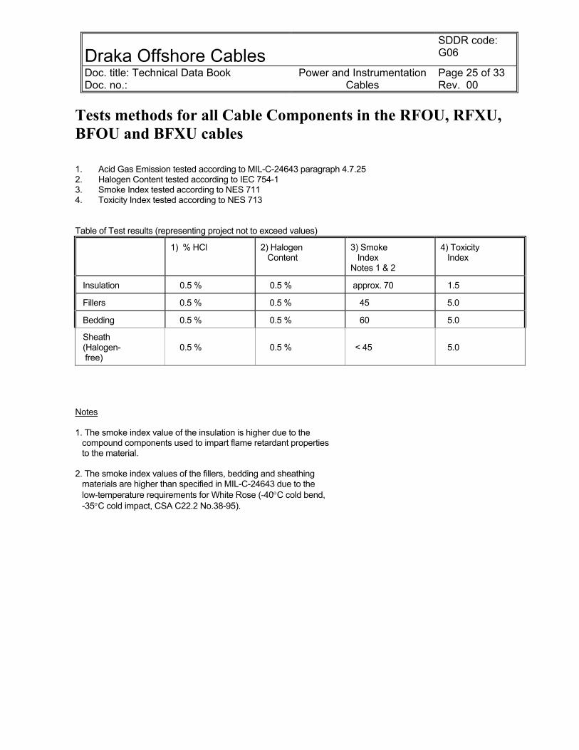
Tests methods for all Cable Components in the RFOU, RFXU, BFOU and BFXU cables 1. Acid Gas Emission tested according to MIL-C-24643 paragraph 4.7.25 2. Halogen Content tested according to IEC 754-1 3. Smoke Index tested according to NES 711 4. Toxicity Index tested according to NES 713 Table of Test results (representing project not to exceed values)
1) % HCl 2) Halogen Content
3) Smoke Index Notes 1 & 2
4) Toxicity Index
Insulation 0.5 % 0.5 % approx. 70 1.5
Fillers 0.5 % 0.5 % 45 5.0
Bedding 0.5 % 0.5 % 60 5.0
Sheath (Halogen- free)
0.5 %
0.5 %
< 45
5.0
Notes 1. The smoke index value of the insulation is higher due to the compound components used to impart flame retardant properties to the material. 2. The smoke index values of the fillers, bedding and sheathing materials are higher than specified in MIL-C-24643 due to the low-temperature requirements for White Rose (-40°C cold bend, -35°C cold impact, CSA C22.2 No.38-95).
Draka Offshore Cables
SDDR code: G06
Doc. title: Technical Data Book Doc. no.:
Power and Instrumentation Cables
Page 26 of 33 Rev. 00
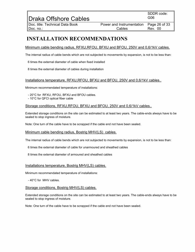
INSTALLATION RECOMMENDATIONS Minimum cable bending radius, RFXU,RFOU, BFXU and BFOU, 250V and 0,6/1kV cables. The internal radius of cable bends which are not subjected to movements by expansion, is not to be less than: 6 times the external diameter of cable when fixed installed 8 times the external diameter of cables during installation Installations temperature, RFXU,RFOU, BFXU and BFOU, 250V and 0,6/1kV cables.. Minimum recommendated temperature of installations:
- 20°C for RFXU, RFOU, BFXU and BFOU cables. - 10°C for QFCI optical fiber cable
Storage conditions, RFXU,RFOU, BFXU and BFOU, 250V and 0,6/1kV cables.. Extended storage conditions on the site can be estimated to at least two years. The cable-ends always have to be sealed to stop ingress of moisture. Note: One turn of the cable have to be scrapped if the cable end not have been sealed. Minimum cable bending radius, Bostrig MHV(LS) cables. The internal radius of cable bends which are not subjected to movements by expansion, is not to be less than: 6 times the external diameter of cable for unarmoured and sheathed cables 8 times the external diameter of armoured and sheathed cables Installations temperature, Bostrig MHV(LS) cables. Minimum recommendated temperature of installations:
- 40°C for MHV cables. Storage conditions, Bostrig MHV(LS) cables. Extended storage conditions on the site can be estimated to at least two years. The cable-ends always have to be sealed to stop ingress of moisture. Note: One turn of the cable have to be scrapped if the cable end not have been sealed.

Draka Offshore Cables
SDDR code: G06
Doc. title: Technical Data Book Doc. no.:
Power and Instrumentation Cables
Page 27 of 33 Rev. 00
STANDARD WOODEN DRUM
Barrel
Flanges, 2-ply(spruce)
Centerhole
Bolts forreinforcing
Material : spruce Flanges : 2-ply, 90° cross grain Barrel : reinforced with through-going bolts Center hole : each drum has a center hole (spindle)
Draka Offshore Cables
SDDR code: G06
Doc. title: Technical Data Book Doc. no.:
Power and Instrumentation Cables
Page 28 of 33 Rev. 00
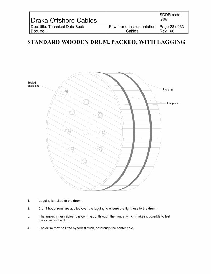
STANDARD WOODEN DRUM, PACKED, WITH LAGGING
Lagging
Hoop-iron
Sealedcable end
1. Lagging is nailed to the drum. 2. 2 or 3 hoop-irons are applied over the lagging to ensure the tightness to the drum. 3. The sealed inner cableend is coming out through the flange, which makes it possible to test the cable on the drum. 4. The drum may be lifted by forklift truck, or through the center hole.

Draka Offshore Cables SDDR code: G06
Doc. title: Technical Data Book Doc. no.:
Power and Instrumentation Cables
Page 29 of 33 Rev. 00
PREPARATION FOR SHIPMENT 1. After inspection and testing withnessed by COMPANY's representative the cable ends are sealed. The cable is packed on our standard wooden drums and lagged. 2. The cable drums are marked in accordance with instructions given in the Purchase Order documents. 3. Both cable ends are free, (the inner end comes out through the drum flange) and the cable can thus be tested while still on drum.
UNPACKING PROCEDURE 1. Remove the hoop-irons, they are not nailed to the lagging. 2. Remove the lagging, which is nailed to the drum flanges. 3. The cable is now ready to be pulled.
SHIPPING AND STORAGE RECOMMENDATIONS The drums may be lifted by forklift truck or through the center hole. The drums must be stored in the upright position, small drums may be stored in two layers, use stoppers at the end of the bottom row. The drums may be sent by rail, ship or air. During shipment the drums are prevented from starting rolling by placing (wooden) stoppers underneath by the flanges, like this:
Draka Offshore Cables SDDR code: G06
Doc. title: Technical Data Book Doc. no.:
Power and Instrumentation Cables
Page 30 of 33 Rev. 00
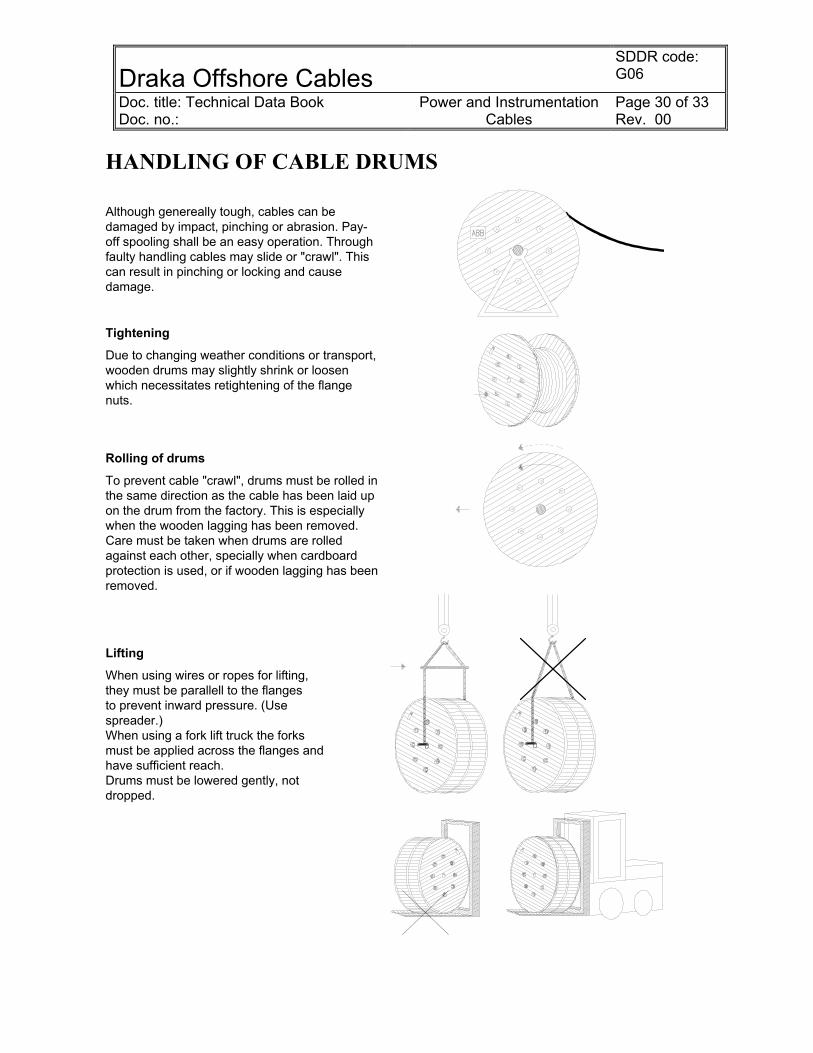
HANDLING OF CABLE DRUMS Although genereally tough, cables can be damaged by impact, pinching or abrasion. Pay-off spooling shall be an easy operation. Through faulty handling cables may slide or "crawl". This can result in pinching or locking and cause damage.
Tightening Due to changing weather conditions or transport, wooden drums may slightly shrink or loosen which necessitates retightening of the flange nuts.
Rolling of drums
To prevent cable "crawl", drums must be rolled in the same direction as the cable has been laid up on the drum from the factory. This is especially when the wooden lagging has been removed. Care must be taken when drums are rolled against each other, specially when cardboard protection is used, or if wooden lagging has been removed.
Lifting When using wires or ropes for lifting, they must be parallell to the flanges to prevent inward pressure. (Use spreader.) When using a fork lift truck the forks must be applied across the flanges and have sufficient reach. Drums must be lowered gently, not dropped.
Draka Offshore Cables
SDDR code: G06
Doc. title: Technical Data Book Doc. no.:
Power and Instrumentation Cables
Page 31 of 33 Rev. 00
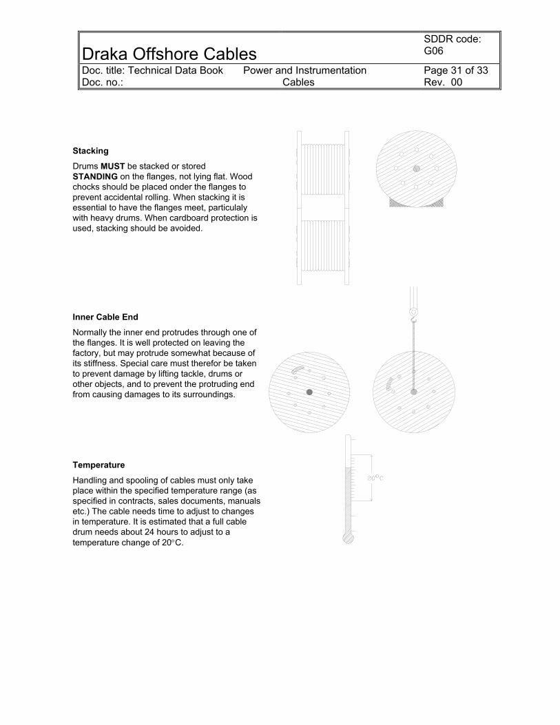
Stacking Drums MUST be stacked or stored STANDING on the flanges, not lying flat. Wood chocks should be placed onder the flanges to prevent accidental rolling. When stacking it is essential to have the flanges meet, particulaly with heavy drums. When cardboard protection is used, stacking should be avoided.
Inner Cable End Normally the inner end protrudes through one of the flanges. It is well protected on leaving the factory, but may protrude somewhat because of its stiffness. Special care must therefor be taken to prevent damage by lifting tackle, drums or other objects, and to prevent the protruding end from causing damages to its surroundings.
Temperature Handling and spooling of cables must only take place within the specified temperature range (as specified in contracts, sales documents, manuals etc.) The cable needs time to adjust to changes in temperature. It is estimated that a full cable drum needs about 24 hours to adjust to a temperature change of 20°C.
Draka Offshore Cables
SDDR code: G06
Doc. title: Technical Data Book Doc. no.:
Power and Instrumentation Cables
Page 32 of 33 Rev. 00
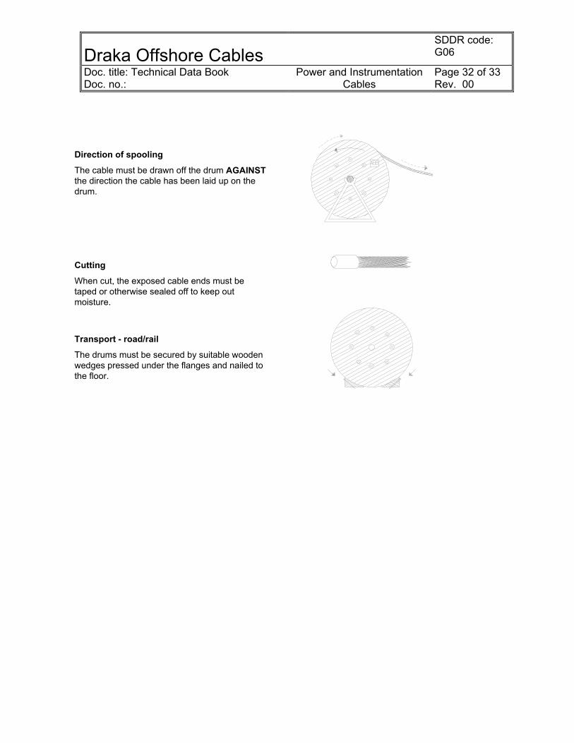
Direction of spooling The cable must be drawn off the drum AGAINST the direction the cable has been laid up on the drum.
Cutting
When cut, the exposed cable ends must be taped or otherwise sealed off to keep out moisture.
Transport - road/rail The drums must be secured by suitable wooden wedges pressed under the flanges and nailed to the floor.

Draka Offshore Cables
SDDR code: G06
Doc. title: Technical Data Book Doc. no.:
Power and Instrumentation Cables
Page 33 of 33 Rev. 00
CODE DESIGNATION This code designation covers the norwegian cables RFXU, RFOU, BFXU, BFOU and QFCI and it does not cover the Bostrig MHV cables. EPR = EPDM - ethylene propylene rubber MICA - Mica Glass Tape HF/FR - Halogenfree thermoplastic or thermoset compound (filling compound) SHF1 - Flame retardant halogen-free thermoplastic compound According to IEC 92-359, type SHF1 SHF2 - Flame retardant halogen-free thermoset compound According to IEC 92-359, type SHF2 (Cables up to and including 36kV) Materials 1.Letter:
Insulation 2.Letter: Bedding/ Sheath
3.Letter: Braid/ Armour
4.Letter: Outher Sheath
Mica/EPR B EPR R Optical fibre in loose tube Q HF/FR (filling Compound) (BF- and RF-cables)
F
Armour, Galvanized Steel Wire Braid C Armour, Tinned Copper Wire Braid O No armour X SHF1 sheath I SHF2 sheath U Additional abbreviation for instrumentation cables: Collective screen cable............................ (c) Individual pair/triple sceened cable........... (i)