basaltperfcon.net/drawings/1296basalt/shop drawings/190918 1505... · 2019-09-19 · product...
TRANSCRIPT

Product Submittals For : ( Townhouses)
Basalt
5058 Cambie Street, Vancouver, BC
Page 1 Title Page
Pages 2-3 Tyvek Commerical Wrap ( Moisture Barrier )
Pages 4 Venture Sheating Tape ( For use with Tyvek )
Pages 5-12 Treated Rainscreen Strapping ( For Cladding )
Pages 13-14 Protecto Wrap ( For Penetrations )
Pages 15-16 Fiberglass Insect Screen ( For Use with Wood Strapping )
Pages 17-20 Alpolic FR Core ACM Panels
Pages 21-23 Hardie Panel Vertical Cladding
Pages 24-29 Hardie Trim Boards
Pages 30-33 Midland Metal Trims ( To be used with Vertical Siding )
Pages 34 Cascadia SMP Flashing Colors ( To be Selected )
Pages 35-36 Westform WF-HF Panel ( To be used as Soffit )
Pages 37-39 Dynomic Tremco FC Caulking ( Sealant )
Pages 40-41 Dynomic Tremco FC Caulking Colors
Issued : September 4, 2019
M.A
Sep 9, 2019
CAM: Revise & Resubmit
CAM: Reviewed for NC only
CAM: Reviewed for NC only
CAM: Reviewed for NC only
CAM: Reviewed for NC only
PLEASE FIND CAMPHORA'S STAMP ON THE DRAWING RELATED WITH ONLY
ACM to be replaced with LongboardV-Groove siding. SI to follow
Soffit to be replaced with Longboard V-Groove siding.SI to follow
Flashing and caulking colours to beselected during review of panel layouts.
Hardi panel and trim to be smooth finish.Painted as per colours on Arch. drawings
SHIFT ARCHITECTURE INC.
ENGINEERED ELEMENTS SHOP DRAWING REVIEW
Reviewed
Reviewed as Noted
Revise and Resubmit
Not Reviewed
Project
Date
Reviewed By
This review by Shift Architecture Inc. is for the sole
purpose of ascertaining conformance with the
general design for architectural features only and
does not in any way constitute review of the design
of engineering elements which form part of the
contract documents prepared by others. This review
shall not mean that Shift Architecture Inc. approves
the detailed design inherent in the shop drawings,
responsibility for which shall remain with the
Contractor submitting same, and such review shall
not relieve the Contractor of the responsibility for
errors or omissions in the shop drawings or of the
responsibility of meeting all requirements of the
contract documents. The Contractor is responsible
for dimensions to be confirmed and correlated at the
job site, for information that pertains solely to
fabrication processes or to techniques of
construction and installation, and for the
coordination of the work of all trades.
✔
9/18/2019
1505
Kevin
Submit layout drawings for review.
TECHNICAL DATA SHEET
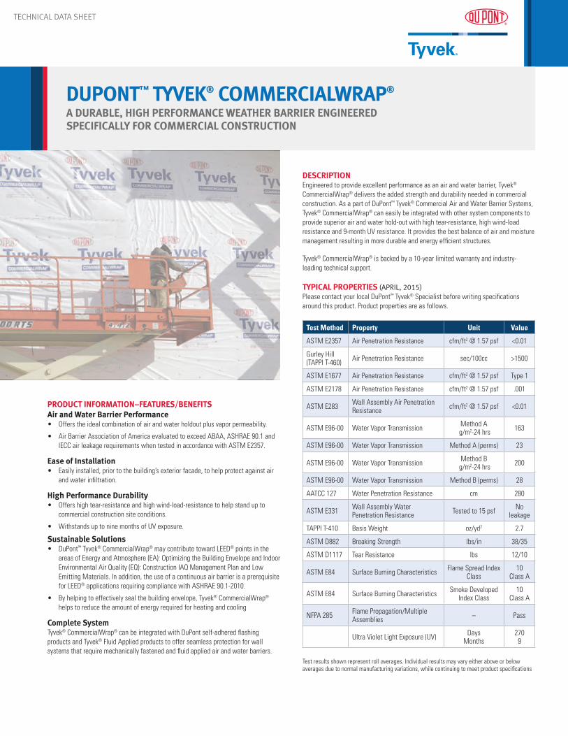
DUPONT™ TYVEK® COMMERCIALWRAP®
A DURABLE, HIGH PERFORMANCE WEATHER BARRIER ENGINEERED SPECIFICALLY FOR COMMERCIAL CONSTRUCTION
PRODUCT INFORMATION–FEATURES/BENEFITSAir and Water Barrier Performance• Offers the ideal combination of air and water holdout plus vapor permeability.
• Air Barrier Association of America evaluated to exceed ABAA, ASHRAE 90.1 and IECC air leakage requirements when tested in accordance with ASTM E2357.
Ease of Installation • Easily installed, prior to the building’s exterior facade, to help protect against air
and water infiltration.
High Performance Durability• Offers high tear-resistance and high wind-load-resistance to help stand up to
commercial construction site conditions.
• Withstands up to nine months of UV exposure.
Sustainable Solutions• DuPont™ Tyvek® CommercialWrap® may contribute toward LEED® points in the
areas of Energy and Atmosphere (EA): Optimizing the Building Envelope and Indoor Environmental Air Quality (EQ): Construction IAQ Management Plan and Low Emitting Materials. In addition, the use of a continuous air barrier is a prerequisite for LEED® applications requiring compliance with ASHRAE 90.1-2010.
• By helping to effectively seal the building envelope, Tyvek® CommercialWrap® helps to reduce the amount of energy required for heating and cooling
Complete SystemTyvek® CommercialWrap® can be integrated with DuPont self-adhered flashing products and Tyvek® Fluid Applied products to offer seamless protection for wall systems that require mechanically fastened and fluid applied air and water barriers.
DESCRIPTIONEngineered to provide excellent performance as an air and water barrier, Tyvek® CommercialWrap® delivers the added strength and durability needed in commercial construction. As a part of DuPont™ Tyvek® Commercial Air and Water Barrier Systems, Tyvek® CommercialWrap® can easily be integrated with other system components to provide superior air and water hold-out with high tear-resistance, high wind-load resistance and 9-month UV resistance. It provides the best balance of air and moisture management resulting in more durable and energy efficient structures.
Tyvek® CommercialWrap® is backed by a 10-year limited warranty and industry-leading technical support.
TYPICAL PROPERTIES (APRIL, 2015)Please contact your local DuPont™ Tyvek® Specialist before writing specifications around this product. Product properties are as follows.
Test Method Property Unit Value
ASTM E2357 Air Penetration Resistance cfm/ft2 @ 1.57 psf <0.01
Gurley Hill (TAPPI T-460) Air Penetration Resistance sec/100cc >1500
ASTM E1677 Air Penetration Resistance cfm/ft2 @ 1.57 psf Type 1
ASTM E2178 Air Penetration Resistance cfm/ft2 @ 1.57 psf .001
ASTM E283 Wall Assembly Air Penetration Resistance cfm/ft2 @ 1.57 psf <0.01
ASTM E96-00 Water Vapor Transmission Method A g/m2-24 hrs 163
ASTM E96-00 Water Vapor Transmission Method A (perms) 23
ASTM E96-00 Water Vapor Transmission Method B g/m2-24 hrs 200
ASTM E96-00 Water Vapor Transmission Method B (perms) 28
AATCC 127 Water Penetration Resistance cm 280
ASTM E331 Wall Assembly Water Penetration Resistance Tested to 15 psf No
leakage
TAPPI T-410 Basis Weight oz/yd2 2.7
ASTM D882 Breaking Strength lbs/in 38/35
ASTM D1117 Tear Resistance lbs 12/10
ASTM E84 Surface Burning Characteristics Flame Spread Index Class
10 Class A
ASTM E84 Surface Burning Characteristics Smoke Developed Index Class
10Class A
NFPA 285 Flame Propagation/Multiple Assemblies – Pass
Ultra Violet Light Exposure (UV) Days Months
2709
Test results shown represent roll averages. Individual results may vary either above or below averages due to normal manufacturing variations, while continuing to meet product specifications

TECHNICAL DATA SHEET
DUPONT™ TYVEK® COMMERCIALWRAP®
A DURABLE, HIGH PERFORMANCE WEATHER BARRIER ENGINEERED SPECIFICALLY FOR COMMERCIAL CONSTRUCTION
PRODUCT DESCRIPTIONTyvek® CommercialWrap® is made from 100% flash spunbonded high density polyethylene fibers which have been bonded together by heat and pressure, without binders or fillers, into a tough durable sheet structure. Additives have been incorporated into the polyethylene to provide ultraviolet light resistance.
INSTALLATION/USE INSTRUCTIONSPlease refer to DuPont Installation Guidelines for complete instructions.
Safety Precautions for UseTyvek® CommercialWrap® is slippery and should not be used in any application where it will be walked on. In addition, DuPont recommends using kick jacks, scaffolding, or lifts for exterior work above the first floor. If ladders must be used, extra caution must be taken to use them safely by following the requirements set forth in ANSI Standards 14.1, 14.2, and 14.5 for ladders made of wood, aluminum, and fiberglass, respectively.
Tyvek® CommercialWrap® is combustible and should be protected from flames and other high heat sources. Tyvek® CommercialWrap® will melt at 275°F (135°C) and if the temperature of the product reaches 750°F (400°C), it will burn and the fire may spread and fall away from the point of ignition. For more information, call 1-800-44-Tyvek.
PreparationNo surface preparation is needed for the installation of Tyvek® CommercialWrap®.
TESTING/CODE COMPLIANCEMoisture Protection – Weather-Resistant BarriersThe 2012 International Building Code (IBC, Section 1403.2 Weather Protection) requires that exterior walls shall provide the building with a weather-resistant exterior wall envelope. This shall include flashing, as described in Section 1405.4. Tyvek® CommercialWrap® and where applicable, DuPont self-adhered flashing and accessory products, have been tested and meet weather-resistant barrier codes and standards requirements. The following test methodologies were used:
• ASTM E331 Standard Test Method for Water Penetration of Exterior Windows, Skylights, Doors, and Curtain Walls by Uniform Static Pressure
• ASTM E2556 Standard Specification for Vapor Permeable Flexible Sheet Water-resistive Barriers intended for mechanical attachment
• ASTM E96-00 Standard Test Methods for Water Vapor Transmission of Materials; Water resistive barriers are typically vapor permeable, which is generally desirable because it allows for drying of incidental moisture intrusion into the wall assembly
• AATCC 127 Hydrostatic Head Test for water-resistant barrier materials, measuring pressure to failure or time of failure at a given pressure
Air Leakage Control — Air BarriersASHRAE 90.1 2010 (American Society of Heating, Refrigerating and Air-Conditioning Engineers) requires that the entire building envelope shall be designed and constructed with a continuous air barrier. This is a mandatory provision for the building envelope. IECC 2012 (International Energy Conservation Code) for commercial buildings also requires a continuous air barrier. These codes are being adopted in many states across the United States. Tyvek® CommercialWrap and where applicable, DuPont self-adhered flashing and accessory products have been tested and meet air barrier codes and standards requirements. The following test methodologies were used:
• ASTM E2357 Standard Test Method for Determining Air Leakage of Air Barrier Assemblies
• ASTM E1677 Standard Specification for an Air Retarder (AR) Material or System for Low-Rise Framed Building Walls
• ASTM E2178 Standard Test Method for Air Permeance of Building Materials
• ASTM E283 Standard Test Method for Determining Rate of Air Leakage Through Exterior Windows, Curtain Walls and Doors Under Specified Pressure Differences Across the Specimen
Other• ASTM E 84 Standard Test Method for Surface
Burning Characteristics of Building Materials
• NFPA 285 Standard Fire Test Method for Evaluation of Fire Propagation Characteristics of Exterior Non-Load-Bearing Wall Assemblies Containing Combustible Components
Tyvek® CommercialWrap®, in conjunction with DuPont self-adhered flashing and accessory products, have been evaluated according to Air Barrier Association of America (ABAA) protocol and are listed at the ABAA website under “ABAA evaluated Air Barrier Assemblies”, www.airbarrier.org
NOTICETyvek® CommercialWrap® should be covered with the facade within nine months to limit UV exposure. Follow facade manufacturer’s installation and maintenance requirements in order to maintain water holdout.
MATERIAL STORAGE/DISPOSALTyvek® CommercialWrap® should be stored in a clean, dry environment.
PACKAGINGTyvek® CommercialWrap® is available the following roll sizes:
• 5’ x 200’ (1.5 x 61m)
• 10’ x 125’ (3.1 x 38.1 m)
WARRANTYBacked by a limited product warranty, see www.weatherization.tyvek.com.
Copyright © 2015 E. I. du Pont de Nemours and Company. All Rights Reserved. The DuPont Oval Logo, DuPont™, The miracles of science™, CommercialWrap® and Tyvek®, are registered trademarks or trademarks of E.I. du Pont de Nemours and Company or its affiliates. K-27289-1 (5/15)

VentureTape® 1585CW-P2 is a is a polypropylene sheathing tape coated with an aggressive acrylic
pressure sensitive adhesive (PSA) designed for use as a closure system and vapor seal on all interior
and exterior sheathing materials. VentureTape 1585CW-P2 exceeds most building code requirements
and can be used for new construction as well as repair on all vapor barrier materials. CCMC approved,
VentureTape® 1585CW-P2 is the highest performing, highest value product on the market today.
Features & Benefits
• High performance sheathing tape installs and performs well over a wide temperature range
• Excellent vapor barrier tape on polyethylene film
• Performs well as a seam tape on extruded foam products such as Styrofoam® and
Foamular®
• Applies to all major housewraps including Tyvek® and Typar®
• Great for use as a sealing tape on DensGlass
Gold® and other sheathing brands
SHEATHING TAPE
1585CW-P2
Biaxially oriented polypropylene (BOPP) Acrylic adhesive
Typical values are not intended to be used for specification development. Technical data is believed to be true and accurate; Venture Tape recommends that the purchaser test for fitness of use in all applications.
Product Construction
Product Configurations
• 1 7/8” x 72 yards & 2 1/2” x 72 yards standard • Custom rolls available on request
Contact Venture Tape today for a complete
list of products or a free sample
Toll Free North America 800-343-1076
From United Kingdom 0-800-962-957
From Australia 1-800-122-797
www.venturetape.com
0811
Test Typical Value
Typical Value
(Metric)
Test
Method
Product Thickness 3.0 mils 0.08 mm PSTC-133 Peel AdhesionΔ to stainless steel 45 oz/in 12.5 N/25 mm PSTC-101 to polyethylene 16 oz/in 4.5 N/25 mm PSTC-101 to Tyvek® 25 oz/in 6.9 N/25 mm PSTC-101 Shear Adhesion >24 hrs @ 2.2 psi >24 hrs @ 15.2 kPa PSTC-107 Tensile Strength 20 lb/in 90.4 N/25 mm PSTC-131 Elongation 130 % 130 % PSTC-131 WVTR 0.061 perms ASTM E96 Service Temperature -40 to 185 °F -40 to 85 °C
Δ - 20 minute dwell
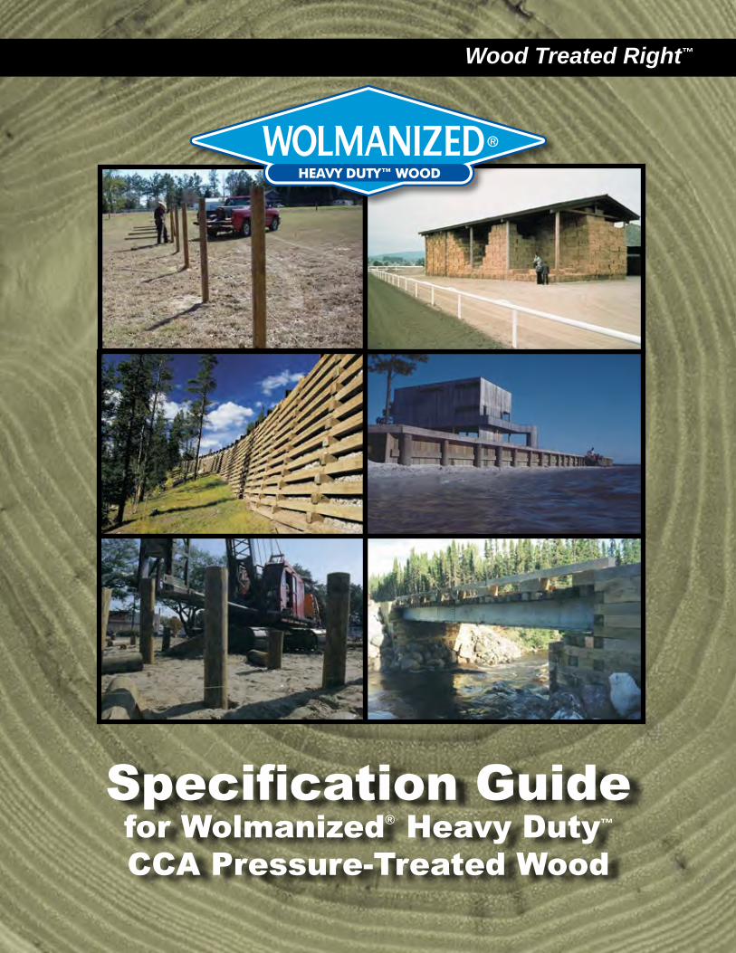
Specification Guide for Wolmanized® Heavy Duty™ CCA Pressure-Treated Wood
Wood Treated Right™

www.WolmanizedWoodHD.com2
Wolmanized® wood is poles, piles, timbers, posts, or plywood that is pressure-treated with CCA preservative to provide structural protection from termites and fungal decay. For 75 years, CCA-treated wood has been specified in a wide variety of applications. When used and handled as recommended, it presents no unusual risks to people, plants, and animals. Its use provides environmental benefits as well as decades of service.
Wolmanized® Heavy Duty™ Pressure-Treated Wood
ContentsWhat is CCA &How Does It Work? ........................................................ 3
Retention, Penetration, Use Category System .................................................... 4
Recommended Hardware, Species, Design Values, Marine Grade ................................................................ 5
Safety & Handling, The Treating Process ...................................................... 6
Model Specification ....................................................... 7

Specify Wolmanized® wood and plywood for applications in which conditions conducive to termites and fungal decay are present. This includes wood that will be in contact with water, soil, concrete or masonry, subject to periodic wetting, or exposed to moisture or high humidity. Wolmanized® wood is suitable for a wide variety of applications, including:• Piling
• Poles, building & utility
• Plywood
• Highway guard & sign posts
• Agricultural fence posts (round, half-round, quarter-round)
• Lumber for salt water use
• Marine construction
• Permanent Wood Foundations
• Sawn structural timbers
• Sawn crossarms
• Structural glued laminated members
• Structural composite lumber
• Shakes and shingles
• Roller coasters
• Cooling towers
For residential and other applications requiring a copper-based preservative, specify Wolmanized® Outdoor® wood.
• Protection against rot, fungal decay, and termites
• 75-year successful track record
• Easy to work with, repair, and modify with common tools
• Strong, resilient, versatile, and economical
• Backed by Lonza Wood Protection, the world’s leader in wood preservation technology
The chemical used to preserve Wolmanized® pressure-treated wood is a mixture of oxides of copper, chromium, and arsenic and known as CCA. The preservative has been formulated to render wood useless as a food substance for termites and fungi while keeping the wood attractive, clean, odorless, non-staining, and safe to handle when done as recommended.
Unlike commercially produced trivalent arsenic, the arsenic in Wolman® CCA is in the form of inorganic pentavalent arsenate — a naturally occurring trace element. In the treatment process, described on Page 6, the pentavalent arsenate becomes fixed, or chemically bound, in the wood cells as highly leach-resistant insoluble precipitates.
The reaction of chromated copper arsenate with the wood substrate is termed “fixation” because the preservative compounds are fixed in the treated wood in a highly insoluble state. However, some chemical may migrate from treated wood into surrounding soil over time and may also be dislodged from the wood surface upon contact with the skin. Fixation accounts for the permanency of the preservative in the treated wood, which explains the leach resistance and durability of the product.
The fixation mechanism is complex and the reactions involved are primarily dependent upon wood species, preservative formulation, concentration, and temperature. The result, however, is that the preservative becomes leach-resistant precipitates.
When to Specify
Wood Treated Right™ 3
Features & Advantages
What is CCA and How Does It Work?Chemical Composition of CCA-C
All Wolmanized® Heavy Duty™ wood is treated with CCA-Type C, which is composed of the following:
Hexavalent Chromium (CrO3) 47.5%
Copper (CuO) 18.5%
Arsenic (As2O5) 34.0%
More on Fixation

The effectiveness of preservatives at various retentions in different species is evaluated using test stakes.
Wolmanized® pressure-treated wood is treated to various retention levels that are intended to protect the wood for particular applications. Retention levels indicate the amount of preservative retained in the wood in a specific assay zone. In North America, retention is expressed in pounds per cubic foot (pcf).Retention levels or treating quality procedures are marked on Wolmanized® wood. The accompanying table outlines CCA retention levels required by the American Wood Protection Association for various applications.Retention varies with depth in the wood, so preservative penetration also affects wood longevity. In species with large amounts of sapwood, such as southern and red pine, the preservative must penetrate 2.5 inches or 85% of the sapwood to meet standards. In western species that are predominantly heartwood, the wood is incised to ensure
1Wolman® CCA preservative meets or exceeds AWPA P5 and Federal Standard TT-W-550. The treating process and the results above meet or exceed Fed-eral Specification TT-W-571 and AWPA Commodity Standards as applicable. 2For round piling used in the northern zone (Long Island and north on the East coast, north of San Francisco on the West coast), a retention of 1.50 pcf is acceptable (UC5A).
The American Wood Protection Association, which establishes the standards for preser-vatives and treated wood, has adopted a Use Category system, based on the service conditions for wood rather than on wood commodities. It is designed to reduce confusion among specifiers and consumers. Most building codes reference AWPA standards, so the Use Category system is replacing the older Commodity standards in codes. At right is a summary of AWPA Use Categories.
Shown in yellow are categories in which there are ongoing uses for CCA-treated wood.
Retention & Penetration
www.WolmanizedWoodHD.com4
a treated shell, and any cut surfaces should be field-treated in accordance with AWPA standard M4 with a topical preservative.
AWPA Retention Requirements1
Application Use Category CCA (pcf)
LUMBER, TIMBERS, AND PLYWOODAbove Ground 3B 0.25Ground/Fresh Water Contact 4A 0.40Salt Water Splash 4B 0.60Permanent Wood Foundation 4B 0.60Salt Water Immersion 5B 2.50
POLES AND PILESStructural Poles 4B 0.60Foundation/Fresh Water 4C 0.80Salt Water Immersion 5B 2.502
AWPA Use Category System Category DescriptionUC1 Interior, not in contact with ground or foundation
UC2 Interior, subject to dampness
UC3A Exterior, above ground, coated
UC3B Exterior, above ground, may be finished
UC4A Exterior, ground or freshwater contact in areas with low risk
UC4B Exterior, ground or freshwater contact, severe environments, high potential for deterioration
UC4C Exterior, ground or freshwater contact, very severe conditions or very critical structural components
UC5A Saltwater exposure — north of San Francisco and Long Island
UC5B Saltwater exposure — south of San Francisco on West coast, New Jersey through Georgia on East coast
UC5C Saltwater exposuure — south of Georgia, Gulf Coast
UCFA Fire protection, weather-shielded
UCFB Fire protection, exterior

Wood Treated Right™ 5
Recommended HardwareThe conditions that are conducive to attack by fungal decay and termites also promote metal corrosion. Hot-dipped galvanized fasteners (meeting ASTM A 153) and connectors (ASTM A 653 Class G185 sheet), or better, are recommended for protection against the effects of moisture often present where treated wood is used. For Per-manent Wood Foundations, use 304
or 316 stainless steel. Aluminum should not be used in direct contact with this wood.
Typically, the heartwood – the center part of the tree – may be quite dense and less porous than the sapwood – the younger, outer portion of the tree. The heartwood is naturally more resistant to attack by pests, but it is also less accepting of preservative. Therefore, in marine conditions, for example, where wood-destroying organ-isms are a threat, it is wise to specify wood with a minimum of heartwood exposed (seawall grade) to be assured of adequate preservative protection.
The following species of wood can be effectively treated with Wolman® CCA preservative in accordance with American Wood Protection Association standards. Although these species are listed by AWPA, reaching required penetration and retention levels is very difficult in some of them. The term “treated to refusal” indicates that the wood has retained as much preservative as possible, but not enough to meet standards or ensure good performance.
• Southern Pine Group• Ponderosa Pine• Red Pine• Western Red Cedar• Hem-Fir Group*• Jack Pine*• Lodge Pole Pine*• Sugar Pine*• White Pine*• Radiata Pine• Caribbean Pine• Coastal Douglas Fir*• Western Larch*• Redwood*• Sitka Spruce*
*In order to secure penetration of preservative in these species, incising (puncturing the lateral surfaces of the wood) is required.
Since pressure treatment with Wolman® CCA preservative does not alter the natural characteristics of wood, the design values for untreated lumber and plywood should be used in accordance with the National Design Specification for Wood Construction issued by the American Forest and Paper Association.Wood products which have been preservative-treated are referenced in Section 4.3.13 and 6.1.4. If lumber is not dried after treatment, or if the end use will result in a moisture content exceeding 19%, wet service factors shall be applied (see 4.1.4 and 4.3.3).In addition, load duration factors greater that 1.6 shall not apply to structural members. The design values for all acceptable species and grades of lumber are given in the Supplement to the National Design Specification.
Heartwood vs. Sapwood
Treatable Species
Design Values
Marine Treated Wood/Seawall GradesMarine treated lumber, timber and piles are pressure-treated with higher concentrations of Wolman® CCA preservative to withstand the harsh exposures and destructive organisms common in marine environments. Retention levels range from 0.60 pcf for saltwater splash to 2.50 pcf for saltwater immersion. Marine treated wood should be specified for all marine applications, including piling and bulkheads. To ensure adequate treatment against marine borers, two lumber grades have been established for saltwater applications. “Marine” grade, free of heartwood on all four sides, is appropriate where all sides are vulnerable to marine organisms, such as in jetties. “Seawall” grade, which is suitable for sheet piling, is heartwood-free on one wide side (marked “This side seaward”) and on both narrow sides: only the side intended to face earth may have exposed heartwood.
Heartwood
Sapwood

www.WolmanizedWoodHD.com6
The Wolman® Treating Process
Safety & HandlingThe fixation which occurs subsequent to the treating process makes Wolmanized® wood safe for the environment and for the individual user when handled as recom-mended. Once the Wolman® CCA is fixed in the wood cells, it is highly leach-resistant. With more than seven decades of usage, its harmlessness to people, plants, pets, and the environment has been documented by academic and governmental researchers and agencies.
As a federally registered pesticide, Wolman® CCA preservative undergoes a formal investigation and evaluation by the Environmental Protection Agency periodically. Based on an abundance of documentary evidence, the EPA deems Wolmanized® wood to be suitable for uses described in this brochure.
The basic treating process is simple and highly controlled.
Lumber, timbers, or plywood is loaded onto tram cars. The trams are moved into a large, horizontal treating cylinder.The cylinder door is sealed and a vacuum is applied to remove air from the cylinder and the wood cells.Preservative solution is introduced into the cylinder while under vacuum.The pressure raised to about 150 pounds per square inch, forcing CCA into the wood. Treating time varies depending on species of wood, commodity being treated, and the amount of preservative to be impregnated. At the end of the process, excess treating solution is pumped out of the cylinder and back to a storage tank for later re-use.A purge of two cylinder volumes of air is followed by final vacuum to remove excess preservative from wood cells. The cylinder door is opened and the trams are pulled out. The wood is wet, so it is kept on a concrete pad until any dripping ceases.
1
3
5
2
4
6
1
3
5
2
4
6
Other agencies also oversee aspects of the production, transportation, and use of CCA and CCA-treated wood. Material Safety Data Sheets are available from the treating companies licensed to manufacture Wolmanized® wood.

Wood Treated Right™ 7
Model SpecificationThe following paragraphs are for insertion into a section of generic specifications or generic/pro-prietary specifications covering rough carpentry to include preservative treated wood. Notes shown in italics should not be included in the final specification.
PART 1 GENERAL1.01 REFERENCESA. American Wood Protection Association (AWPA)
Book of Standards:1. U1 – Use Category System: User Specification for Treated Wood.2. T1 – Processing and Treatment Standard.3. P5 – Waterborne Preservatives.4. M4 – Care of Preservative-Treated Wood Products.
A. National Institute of Standards and Technology (NIST):
1. PS 1, U.S. Product Standard for Construction and Industrial Plywood.
2. PS 20, American Softwood Lumber Standard.
A. Western Wood Preservers Institute1. Best Management Practices for the Use of
Treated Wood in Aquatic Environments.
1.02 QUALITY ASSURANCEA. Qualifications:1. Treatment Facility: Provide treated materials that
have been produced under the appropriate ASTM or ANSI standard or an ALSC recognized quality assurance program.
1.03 DELIVERY, STORAGE, AND HANDLINGIf drying after treatment is selected in part 2, retain the two paragraphs below.A. Packing and Shipping:1. Provide waterproof covers for preservative
treated wood during shipment.
Storage and Protection:1. Store preservative treated wood off the ground
and protected from the weather.
PART 2 PRODUCTS2.01 MANUFACTURERSA. Preservative: Wolman® CCA Type C; Lonza
Wood Protection
2.02 MATERIALSLumber for preservative treatment must conform to the following specifications. Select grade and species below. Other grades and species may be acceptable, contact Lonza to verify.
A. Lumber: In accordance with NIST PS 20 and as follows:
1. Grade: No. 11. Grade: No. 21. Grade: No. 1 Dense.1. Grade: No. 2 Dense.1. Grade: Select Structural.2. Species: Southern pine.2. Species: Red pine.2. Species: Ponderosa pine.2. Species: Hem-fir.3. Surfacing: S4S.3. Surfacing: S1S2E.3. Surfacing: Rough.4. Moisture Content: 19%, maximum.
Plywood for preservative treatment must conform to the following specifications. Select panel grade, exposure durability, species group, and structural rating from below.B. Plywood: In accordance with NIST PS 1
and as follows:1. Panel Grade: A-C.1. Panel Grade: B-C.1. Panel Grade: C-C.1. Panel Grade: C-D.2. Exposure Durability: Exterior.2. Exposure Durability: Exposure 1.3. Species Group: 1.3. Species Group: 2.4. APA Structural Rating: Structural I.4. APA Structural Rating: Structural II.
C. Preservative: CCA Type C in accordance with AWPA P5 and formulated using only the oxide form of the chemicals.
2.03 PRESERVATIVE TREATMENTSelect required end uses below.A. Pressure Treatment: In accordance with
the requirements of AWPA Standard U1 and in accordance with the following Commodity Specifications:
1. Sawn Products2. Posts3. Poles4. Round Timber Piling5. Wood Composites6. Marine (Salt Water) Applications
Select required applications below.B. Preservative Retention: In accordance
with the specified standard, determined in the specified zone for the following applications:
1. Above Ground.2. Ground or Fresh Water Contact.3. Wood Foundation or Structural Poles.4. Salt Water Immersion.A. Moisture Content: Drying after treat-
ment is not required.
Select Above or Below.B. Moisture Content: Dry after treatment
as follows:1. Lumber: 19%, maximum.2. Plywood: 18%, maximum.3. Plywood: 15%, maximum (for Perma-
nent Wood Foundation).
Retain below if fixed preservative is required for aquatic environments.A. Pressure Treatment of Materials for
Aquatic Environments: In accordance with the Best Management Practices published by the Western Wood Preserv-ers Institute.
2.04 SOURCE QUALITY CONTROLA. Inspection:1. Untreated Material: Lumber: Provide lumber that has been
inspected and graded before treatment by an ALSC recognized grading agency.
Plywood: Provide plywood that has been inspected and graded before treatment by a code-recognized inspection and testing agency.
Poles: Provide poles that have been inspected and graded before treatment in accordance with ANSI standards.
Piling: Provide piling that has been inspected and graded before treatment in accordance with ASTM standards.
1. Treated Material: Provide treated material that bears the quality mark of an ALSC-recognized agency, appropriate industry quality monitoring system, or accepted third-party agency that assures proper treatment for the intended use.
PART 3 EXECUTION 3.01 INSTALLATIONBelow is not generally required for pine spe-cies less than 5 inches thick in the eastern and central U.S. No other special installation specifications are required for preservative treated wood.A. Surface Treatment of Field Cuts: Treat
field cuts on members that provide structural support to a permanent structure in accordance with AWPA Standard M4.

It’s wood.In addition to the treatments that enable the wood to last a long time or resist flames, our brands have all of the environmental and other advantages associated with wood itself. They extend forest resources; the source is a renewable resource grown on managed timber-lands, requiring less energy to produce than alternative building materials and offer-ing greater insulation value; trees absorb carbon dioxide and wood products sequester carbon, two features that reduce greenhouse gas; and, because of its lighter weight, wood can often be installed with lighter equipment having less environmental impact. Wood offers excellent workability with common construction skills and tools, plus it provides design flexibility and economy. Wood is generally less costly than alternative building materials and is considered easier to work with, not to mention aesthetically preferable in many applications.
Where enhanced climbing or color is desired, ask about ET® additive, available in clear and brown formulations.
For other applications, consider these respected brands.
Other Products in the Wolmanized® Wood Family
Wolmanized® Outdoor® wood www.WolmanizedWood.com
An effective, proven choice for residential and commercial applications.
Dricon® FRT woodwww.Dricon.com
Fire retardant treated lumber and plywood for weather-shielded applications. Also available, FRX® wood for exterior applications.
Lonza Wood Protection678.627.2000 • [email protected]
© 2012 Arch Wood Protection, Inc., a Lonza company WOL-0047-R5
Chemonite® ACZA-treated woodwww.Chemonite.com
Heavy duty material for commercial, industrial, and marine applications; especially beneficial for Douglas fir and other hard-to-treat species.

PW100/40 11/09
TECHNICAL DATA SHEET
PW 100/40™ Air/Vapor Barrier Tape & Thru Wall Flashing
TECHNICAL DATA Properties Test Method Test Results Color White/Gray Thickness 40 mil Tensile Strength ASTM D412 975 psi Elongation (adhesive only) ASTM D412 500% Permeance ASTM E96 0.01 perms max Nail Sealability ASTM D1970 Pass Operating Temperature 45ºF to 240ºF (7ºC to 116ºC)
PACKAGING Roll Width: 4”, 6”, 9”, 12”, 18”, 24”, 36” Roll Length: 75’ DESCRIPTION PW 100/40™ is a cold applied self-adhering membrane composed of a tough cross laminated High Density Polyethylene coated on one side with a layer of recycled butyl hybrid adhesive. FEATURES
- Proprietary RECYCLED butyl hybrid adhesive - 120 day exposure rating - Fully adhered system - Seals around properly installed fasteners - Compatible with and will adhere to most construction surfaces¹ - Forms a positive air/vapor barrier²
USES Used as a full building wrap in envelope applications in cavity wall construction as an air/vapor barrier membrane*. Used as a complete waterproof self-adhered flashing for window and door installations to create a positive air/vapor barrier in everyday construction. Safe for use on most wood, wood clad, aluminum, fiberglass and vinyl windows and doors Sealing around skylights Sealing joints in exterior sheathing Sealing penetrations in roof and wall systems LIMITATIONS Not recommended for use on windows or doors that incorporate a plasticized nailing flange or drip cap, consult window manufacturer to determine nailing flange type. Not recommended for use over or near solvent based sealants. See Technical Letter Chemical Compatibility. Not recommended for use over or in contact with PVC roof coverings. Not recommended in high temperature applications to exceed 240ºF (116ºC). SHELF LIFE PW 100/40 maintains optimum initial adhesion to substrates when used within one year from the date of manufacture. STORAGE PW 100/40 should be stored in the original, unopened container at ambient temperatures between 40°F to 90°F (5°C to 32°C). Storage area should remain dry and out of direct sunlight. Do not remove materials from original containers until ready for use. Do not double stack pallets.

PW100/40 11/09
PREPARATION All surfaces shall be clean, dry and free of any foreign materials. The surface shall be free of gaps, sharp edges and protrusions. Metal surfaces may need to be solvent wiped and/or abraded to achieve optimum adhesion. ¹ Note: If surface is DensGlass Gold®, OSB, Concrete block (CMU), masonry, fiber board sheathing or cannot be cleaned to a like new surface or the surface is damp or below 45°F (7°C), primer should be used prior to the application of the membrane. Some housewrap materials may require primer, test for adhesion prior to full application. Refer to: Technical Letter Primer Selection for more information. Protecto Wrap Company recommends testing substrates for adhesion. If adhesion to substrate is found to be marginal, then a primer shall be used to ensure optimal adhesion. Refer to: Technical Letter Primer Recommendations; See Technical Letter, Adhesion to Substrates. APPLICATION For full wall air/vapor barrier applications: PW 100/40 can be installed horizontally or vertically and must form water shedding laps. Side laps should be a minimum of 2”, end laps should be a minimum of 4”, all membrane terminations should be sealed with a 1” wide troweled bead of JS 160-H Mastic (or equivalent, contact Protecto Wrap Company Technical Representative for assistance).
For window and door applications: Apply first piece of PW 100/40 to the rough opening sill; firmly roll into place using a hand roller (J-roller, Laminate roller) to smooth out any wrinkles, air bubbles or creases that would allow water to migrate behind the membrane. Set window into the rough opening and fasten per window manufacturer’s instructions. Apply vertical pieces over the nailing flange at the sides of window frame, firmly roll into place using a hand roller to smooth out any wrinkles, air bubbles or creases, apply the final piece over the top nail flange and overlap the vertical sides pieces, firmly roll into place using a hand roller to smooth out any wrinkles, air bubbles or creases. * Additional methods and details can be found at www.protectowrap.com or call (800) 759-9727.
CLEAN UP Dispose of waste in accordance to local requirements. Control worksite so that boxes and release liner do not present a hazard. Packaging materials and release liner can be recycled. CAUTION PW 100/40 should not come into contact with solvent based products, polysulfide’s, plasticized PVC roofing materials or high concentrations of resins (pitch). ² Note: It is very important in full coverage envelope applications that the PW 100/40 is tightly sealed into the roofing and below grade waterproofing systems and perimeter flashings to retain the integrity of the vapor barrier throughout the entire structure. In full building envelope applications the dew point of the wall assembly must be engineered to the exterior of the building. LIMITED WARRANTY This product is covered by the Protecto Wrap Standard 10 Year Limited Warranty.
PROTECTO WRAP COMPANY 1955 South Cherokee Street
Denver, CO 80223 (303) 777-3001 • (800) 759-9727
FAX (303) 777-9273 www.protectowrap.com

Technical Data Screening Products
Product Introduction
FiberLink screening products are constructed of vinyl-coated fiberglass or polyester yarns. The screen is strong, long-lasting and is not easily damaged. Its main usage is for windows, doors, patio doors, patio enclosures and other outside structures to allow airflow but resist insects.
Product Description The screening products that FiberLink provides include the following: 1. StarMesh (X1) As the standard fiberglass insect screening, the main features of X1 are: corrosion resistant, good ventilation, high color stability, stable dimension, long-lasting, and easily cleaned. Fiberglass screen is available in a choice of several mesh sizes, widths and colors which can be customized upon request. Fiberglass screen is the material of choice for many builders in residential and commercial applications for its translucent appearance and low maintenance characteristics. 2. Retractable Screen (X2) X2 is the same standard fiberglass screen as StarMesh, except that this mesh is stiffer than X1 screening. The stiffness of this material makes it ideal for the retractable window screen or door, which can help save the inconvenience and expense of a permanent installation. It is easy to be installed, removed and reused.
3. Patio Screen (X4) The main features of X4 are: corrosion resistant, good ventilation, high color stability, stable dimension, long-lasting, and easily cleaned. X4 is available in a choice of several mesh sizes, widths and colors which can be customized upon request. Fiberglass screen is the material of choice for many builders in residential and commercial applications for its translucent appearance and low maintenance characteristics. 4. LiteMesh Screen (X5) LiteMesh screen offers better visibility without compromising durability. In fact, you can enjoy up to 50% more natural light and dramatically improved airflow versus standard screening. The polyester screening is easy to install while being durable and resistant to the elements. LiteMesh Screen helps filter sunlight and is ideal for applications including windows, doors, porches, gazebos and screen rooms. 5. Pet Screen (X6) Pet Screen is an ultra strong screening offering the optimal solution for tears and damage caused by household pets. This screening is much heavier than traditional fiberglass or aluminum screening, yet maintains its excellent outward visibility qualities. It can be easily installed anywhere the traditional screening is used, including windows, doors, porches, gazebos and screen rooms.
Packaging Packaging is dependent on the width of screen required. All screens are packaged in plastic see through sheeting to allow at-a-glance product pulling.
Storage Unless otherwise specified, it is recommended to store fiberglass sheet in a cool, dry area. Temperature should not exceed 35°C (95°F) and the relative humidity should be kept below 75%. Fiberglass products must remain in packaging material until just prior to their use. If these conditions are respected, the fiberglass product should not undergo significant changes when stored for extended periods of time.
Stacking To ensure safety and avoid damage to the product, skids should not be stacked more than three high.
VALLEYWOOD BUSINESS PARK - 55 Valleywood Drive, Markham Ontario L3R 5L9 Canada Tel: 905-475-2300 Fax: 905-475-2303

*Choice of mesh sizes, widths, and colors available upon request
Disclaimer of Liability This data is offered solely as a guide in the selection of a reinforcement. The information contained in this publication is based on actual laboratory data and field test experience. We believe this information to be reliable, but do not guarantee its applicability to the user’s process or assume any liability arising out of its use or performance. The user, by accepting the products described herein, agrees to be responsible for thoroughly testing any application to determine its suitability before committing to production. It is important for the user to determine the properties of its own commercial compounds when using this or any other reinforcement. Because of numerous factors affecting results, we make no warranty of any kind, express or implied, including those of merchantability and fitness for a particular purpose. Statements in this data sheet shall not be construed as representations of warranties or as inducements to infringe any patent or violate any law, safety code or insurance regulation.
Product Code Unit X1/X2 X4 X5 X6
Weave Plain Plain Plain Plain
Construction 18 x 16 18 x 14 20 x 20 15 x 12
Weight g/m2 115 ± 5 150 ± 5 80 ± 4 400 ± 20
Warp yarns/inch 18 ± 0.5 18 ± 0.5 20 ± 0.5 15 ± 0.5
Weft yarns/inch 16 ± 0.5 14 ± 0.5 20 ± 0.5 12 ± 0.5
Standard Width inch 16 to 120 16 to 120 16 to 120 16 to 120
Length/Roll feet 100 & 600 100 100 100
Yarn Diameter mm/inch 0.28 / 0.011 0.33 / 0.013 0.24 / 0.0095 0.62 / 0.0244
LOI % ≥ 55 ≥ 55 - -
Break Strength (MD) N ≥ 260 ≥ 580 250 1210
Break Strength (CD) N ≥ 240 ≥ 500 227 996
Glass Content % 32 32 32 32
PVC Content % 68 68 68 68
VALLEYWOOD BUSINESS PARK - 55 Valleywood Drive, Markham Ontario L3R 5L9 Canada Tel: 905-475-2300 Fax: 905-475-2303

TECHNICALWE UNDERSTAND
TECH
NIC
AL
BRO
CHU
RE
PLEASE PROVIDE TEST S134 RESULT ACCORDING TO 3.1.5.5.(3)(4)
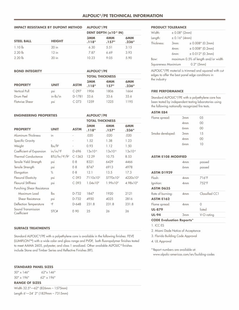
ALPOLIC®/PE TECHNICAL INFORMATION
IMPACT RESISTANCE BY DUPONT METHOD ALPOLIC®/PE
DENT DEPTH (x10-2 IN)
3MM .118"
4MM .157"
6MM .236" STEEL BALL HEIGHT
1.10 lb 20 in 6.30 5.51 3.15
2.20 lb 12 in 7.87 6.69 3.93
2.20 lb 20 in 10.23 9.05 5.90
BOND INTEGRITY ALPOLIC®/PE
TOTAL THICKNESS3MM .118"
4MM 157"
6MM .236" PROPERTY UNIT ASTM
Vertical Pull psi C-297 1906 1806 1664
Drum Peel in-lb/in D-1781 33.6 33.6 33.6
Flatwise Shear psi C-273 1259 1225 1195
ENGINEERING PROPERTIES ALPOLIC®/PE
TOTAL THICKNESS3MM .118"
4MM .157"
6MM .236" PROPERTY UNIT ASTM
Aluminum Thickness in - .020 .020 .020
Specific Gravity - - 1.52 1.38 1.23
Weight lbs/ft2 - 0.93 1.12 1.50
Coefficient of Expansion in/in/oF D-696 13x10-6 13x10-6 13x10-6
Thermal Conductance BTU/hr/oF/ft2 C-1363 12.29 10.75 8.53
Tensile Yield Strength psi E-8 8321 6429 4466
Tensile Strength psi E-8 8747 6913 4978
Elongation % E-8 12.1 13.5 17.3
Flexural Elasticity psi C-393 7110x103 5770x103 4220x103
Flexural Stiffness psi C-393 1.04x10⁹ 1.99x10⁹ 4.98x10⁹
Punching Shear Resistance
Maximum Load lbs D-732 1847 1920 2121
Shear Resistance psi D-732 4950 4025 2816
Deflection Temperature oF D-648 231.8 231.8 231.8
Sound Transmission Coefficient STC# E-90 25 26 26
SURFACE TREATMENTS
Standard ALPOLIC ®/PE with a polyethylene core is available in the following finishes: FEVE (LUMIFLON™) with a wide color and gloss range and PVDF, both fluoropolymer finishes tested to meet AAMA 2605, polyester, and class 1 anodized. Other available ALPOLIC ® finishes include Stone and Timber Series and Reflective Finishes (RF).
STANDARD PANEL SIZES
50" x 146" 62"x 146"
50" x 196" 62" x 196"
RANGE OF SIZES
Width 32.5"—62" (826mm – 1575mm)
Length 6’—24’ 2" (1829mm – 7315mm)
PRODUCT TOLERANCE
Width: ± 0.08" (2mm)
Length: ± 0.16" (4mm)
Thickness: 3mm: ± 0.008" (0.2mm)
4mm: ± 0.008" (0.2mm)
6mm: ± 0.012" (0.3mm)
Bow: maximum 0.5% of length and/or width
Squareness Maximium 0.2" (5mm)
ALPOLIC ®/PE material is trimmed and squared with cut edges to offer the best panel edge conditions in the industry
FIRE PERFORMANCE
Standard ALPOLIC ®/PE with a polyethylene core has been tested by independent testing laboratories using the following nationally recognized fire tests.
ASTM E84
Flame spread: 3mm 05
4mm 00
6mm 00
Smoke developed: 3mm 15
4mm 00
6mm 10
ASTM E108 MODIFIED
4mm passed
6mm passed
ASTM D1929
Flash: 4mm 716°F
Ignition: 4mm 752°F
ASTM D635
Rate of burning: 4mm Classified CC1
ASTM E162
Flame spread: 4mm 0
UL-879 listed
UL-94 3mm V-O rating
CODE Evaluation Reports*
1. ICC ES
2. Miami Dade Notice of Acceptance
3. Florida Building Code Approval
4. UL Approval
* Report numbers are available at: www.alpolic-americas.com/en/building-codes

ALPOLIC®/fr TECHNICAL INFORMATION
IMPACT RESISTANCE BY DUPONT METHOD ALPOLIC®/fr
DENT DEPTH (x10-2 IN)4MM .157"
6MM .236" STEEL BALL HEIGHT
1.10 lb 20 in 5.07 3.93
2.20 lb 12 in 5.47 4.72
2.20 lb 20 in 7.40 6.30
BOND INTEGRITY ALPOLIC®/fr
TOTAL THICKNESS4MM .157"PROPERTY HEIGHT ASTM
Vertical Pull psi C-297 427
Drum Peel in-lb/in D-1781 27.6
Flatwise Shear psi C-273 949
ENGINEERING PROPERTIES ALPOLIC®/fr
TOTAL THICKNESS4MM .157"
6MM .236" PROPERTY UNIT ASTM
Aluminum Thickness in - .020 .020
Specific Gravity - - 1.90 1.81
Weight lbs/ft2 - 1.56 2.23
Coefficient of Expansion in/in/oF D-696 13x10-6 13x10-6
Tensile Yield Strength psi E-8 6344 3840
Tensile Strength psi E-8 7126 4266
Elongation % E-8 5.0 2.0
Flexural Elasticity psi C-393 5770x103 4220x103
Flexural Stiffness psi C-393 1.93x10⁹ 4.98x10⁹
Punching Shear Resistance
Maximum Load lbs D-732 2259 —
Shear Resistance psi D-732 4637 —
Deflection Temperature oF D-648 241.8 228.8
SURFACE TREATMENTS
ALPOLIC ®/fr (fire-retardant) with a mineral filled core offers the same flatness, rigidity, workability, formability and quality features of standard ALPOLIC ®/PE. ALPOLIC ®/fr is curvable to a 6" radius and can be joined with hot melt adhesive to form complex shapes. In addition, ALPOLIC ®/fr is available in the same full palette of bright, clean colors and gloss ranges as standard ALPOLIC ®/PE, as well as Stone Series, Anodized and Natural Metals. Extensive fire performance laboratory testing by independent testing agencies in accordance with requirements set forth by IBC has established ALPOLIC ®/fr approval on Type 1, 2, 3, 4 and 5 Construction throughout the United States and Canada when used as a wall cladding material.
FIRE PERFORMANCE
ALPOLIC ®/fr (fire-retardant) has been tested by independent testing laboratories using the following nationally recognized fire tests.
ASTM E84
Flame spread: 4mm 00
Smoke Developed: 4mm 10
Flame spread: 6mm 00
Flame spread: 6mm 00
ASTM E162
Flame Spread: 4mm 0
ASTM E108 MODIFIED Passed
ASTM 1929
Flash: 4mm 811°F
Ignition: 4mm 837°F
The technical information provided herein is intended to provide users and potential users with general product information; this information should not be used as specifications for ALPOLIC ®. Product specifications and product warranty are available upon request from Mitsubishi Chemical Composites America, Inc. The use of ALPOLIC ® and all activities related thereto are the sole responsibility of the user. Always consult local building codes before use. Nothing contained herein is intended to or shall be construed as a warranty, express or implied, including, but not limited to, warranty of merchantability or fitness for a particular purpose, as to ALPOLIC ®. ALPOLIC ® is a registered trademark of Mitsubishi Chemical Corporation.
NFPA 285, INTERMEDIATE SCALE MULTI STORY APPARATUS TEST:
4mm passed
6mm passed
ASTM E119
4mm passed
CAN/ULC S 134M
4mm passed
NFPA 259, POTENTIAL HEAT RELEASE
4mm <6000 BTU/ft2
COMBUSTION GAS TOXICITY PER UNIVERSITY OF PITTSBURGH
"No more toxic than wood."
CODE EVALUATION REPORTS*
1. ICC ES
2. City of Los Angeles Report
3. Miami Dade Notice of Acceptance
4. Florida Building Code Approval
5. New York City (ACM)
(SCM)
(TCM)
6. CAN/ULC S102, S134 & S135
7. ASTM E84 & E119
8. NFPA 285
* Report numbers are available at: www.alpolic-americas.com/en/building-codes

EFFECTUAL
Sing
apor
e C
hang
i Airp
ort T
erm
inal
3, S
inga
pore
ALP
OLIC
®/f
r in
Cus
tom
Met
allic
Fin
ish
Let us know how we can help you make your
design idea a reality. Get more information,
order finish samples and find a fabricator by
calling 1-800-422-7270 or visiting
alpolic-americas.com.
Let’s build.
© 2017 Mitsubishi Chemical Composites America, Inc. All rights reserved. ALPOLIC ® is a registered trademark of Mitsubishi Chemical Corporation. Lumiflon™ is a registered trademark of Asahi Glass Company.
LITAP4000 | REV. 7 | March 2017

Vertical Siding
HS1237-P1/3 1/13
Figure 2
Caulk Joint
leave appropriate gap betweenpanels, then caulk*
water-resistive barrier
2 x 4 stud
“H” Joint
water-resistive barrier
2 x 4 stud
Batten Joint
water-resistive barrier
2 x 4 studFigure 1
Figure 4Recommendation: When installing Sierra 8, provide a double stud at panel joints to avoid nailing through grooves.
Figure 3
moderate contact
keep fasteners 2"away from corners
plate
keep nails3/8" min.
from paneledges
water-resistivebarrier
stud
HardiePanelvertical siding
3/8"
sheathing
upper panel
1/4" gap
Z-flashing
Do notCaulk
lowerpanel
upper panel
1/4" gap
Z-flashing
Do notCaulk
lowerpanel
decorativeband board
water-resistive barrier
water-resistive barrier
GENERAL REQUIREMENTS:• These instructions to be used for single family installations only. For Commercial / Multi-Family installation requirements go to www.JamesHardieCommercial.com• HardiePanel
® vertical siding can be installed over braced wood or steel studs spaced a maximum of 24" o.c. See general fastening requirements. Irregularities in framing and sheathing can mirror through the finished application. James Hardie recommends installing HardiePanel on a capillary break (rainscreen/furring) as a best practice.
• Information on installing James Hardie products over foam can be located in JH Tech Bulletin 19 at www. jamehardie.com• A water-resistive barrier is required in accordance with local building code requirements. The water-resistive barrier must be appropriately installed with penetration
and junction flashing in accordance with local building code requirements. James Hardie will assume no responsibility for water infiltration. James Hardie does manufacture HardieWrap™ Weather Barrier, a non-woven non-perforated housewrap¹, which complies with building code requirements.
• When installing James Hardie products all clearance details in figs. 3,5,6,7,8,9,10 &11 must be followed.• Adjacent finished grade must slope away from the building in accordance with local building codes - typically a minimum of 6" in the first 10'.• Do not install James Hardie products, such that they may remain in contact with standing water.• HardiePanel vertical siding may be installed on vertical wall applications only.• DO NOT use HardiePanel vertical siding in Fascia or Trim applications.• Some application are not suitable for ColorPlus. Refer to ColorPlus section page 3.• DO NOT use stain, oil/alkyd base paint, or powder coating on James Hardie® Products.• For larger projects, including commercial and multi-family projects, where the span of the wall is significant in length, the designer and/or architect should take into
consideration the coefficient of thermal expansion and moisture movement of the product in their design. These values can be found in the Technical Bulletin #8 “Expansion Characteristics” at www.JamesHardie.com.
INSTALLATION:Fastener RequirementsPosition fasteners 3/8" from panel edges and no closer than 2" away from corners. Do not nail into corners. HardiePanel Vertical Siding Installation• Framing must be provided at horizontal and vertical edges for nailing.• HardiePanel vertical siding must be joined on stud.• Double stud may be required to maintain minimum edge nailing distances.
Joint Treatment• Vertical Joints - Install panels in moderate contact (fig. 1), alternatively joints may also be covered with battens, PVC or metal jointers or caulked (Not applicable to ColorPlus® Finish) (fig. 2).• Horizontal Joints - Provide Z-flashing at all horizontal joints (fig. 3).
WARNING: AVOID BREATHING SILICA DUSTJames Hardie® products contain respirable crystalline silica, which is known to the State of California to cause cancer and is considered by IARC and NIOSH to be a cause of cancer from some occupational sources. Breathing excessive amounts of respirable silica dust can also cause a disabling and potentially fatal lung disease called silicosis, and has been linked with other diseases. Some studies suggest smoking may increase these risks. During installation or handling: (1) work in outdoor areas with ample ventilation; (2) use fiber cement shears for cutting or, where not feasible, use a HardieBlade® saw blade and dust-reducing circular saw attached to a HEPA vacuum; (3) warn others in the immediate area; (4) wear a properly-fitted, NIOSH-approved dust mask or respirator (e.g. N-95) in accordance with applicable government regulations and manufacturer instructions to further limit respirable silica exposures. During clean-up, use HEPA vacuums or wet cleanup methods - never dry sweep. For further information, refer to our installation instructions and Material Safety Data Sheet available at www.jameshardie.com or by calling 1-800-9HARDIE (1-800-942-7343). FAILURE TO ADHERE TO OUR WARNINGS, MSDS, AND INSTALLATION INSTRUCTIONS MAY LEAD TO SERIOUS PERSONAL INJURY OR DEATH. SD050905
S M O O T H ■ C E D A R M I L L © ■ S E L E C T S I E R R A 8 ■ S T U C C O
(Not applicable to ColorPlus® Finish)*Apply caulk in accordance with caulk manufacturer’s written application instructions.
EFFECTIVE SEPTEMBER 2013INSTALLATION REQUIREMENTS SINGLE FAMILY ONLY - PRIMED & COLORPLUS® PRODUCTS Visit www.jameshardie.com for the most recent version.
Store flat and keep dry andcovered prior to installation. Installing siding wet or saturated may result in shrinkage at butt joints. Carry planks on edge. Protect edges and corners from breakage. James Hardie is not responsible for damage caused by improper storage and handling of the product.
OUTDOORS1. Position cutting station so that wind will blow dust away from user and others in working area.2. Use one of the following methods: a. Best: i. Score and snap ii. Shears (manual, electric or pneumatic) b. Better: i. Dust reducing circular saw equipped with a HardieBlade® saw blade and HEPA vacuum extraction c. Good: i. Dust reducing circular saw with a HardieBlade saw blade (only use for low to moderate cutting)
INDOORS 1. Cut only using score and snap, or shears (manual, electric or pneumatic). 2. Position cutting station in well-ventilated area
- NEVER use a power saw indoors - NEVER use a circular saw blade that does not carry the HardieBlade saw blade trademark- NEVER dry sweep – Use wet suppression or HEPA Vacuum
Important Note: For maximum protection (lowest respirable dust production), James Hardie recommends always using “Best”-level cutting methods where feasible.
NIOSH-approved respirators can be used in conjunction with above cutting practices to further reduce dust exposures. Additional exposure information is available at www.jameshardie.com to help you determine the most appropriate cutting method for your job requirements. If concern still exists about exposure levels or you do not comply with the above practices, you should always consult a qualified industrial hygienist or contact James Hardie for further information.
SD083105
CUTTING INSTRUCTIONSSTORAGE & HANDLING:
¹For additional information on HardieWrap™ Weather Barrier, consult James Hardie at 1-866-4Hardie or www.hardiewrap.com
IMPORTANT: FAILURE TO INSTALL AND FINISH THIS PRODUCT IN ACCORDANCE WITH APPLICABLE BUILDING CODES AND JAMES HARDIE WRITTEN APPLICATION INSTRUCTIONS MAY LEAD TO PERSONAL INJURY, AFFECT SYSTEM PERFORMANCE, VIOLATE LOCAL BUILDING CODES,
AND VOID THE PRODUCT ONLY WARRANTY. BEFORE INSTALLATION, CONFIRM THAT YOU ARE USING THE CORRECT HARDIEZONE INSTRUCTIONS. TO DETERMINE WHICH HARDIEZONE APPLIES TO YOUR LOCATION, VISIT WWW.HARDIEZONE.COM OR CALL 1-866-942-7343 (866 9HARDIE)

HS1237-P2/3 8/13
Figure 5
Figure 7
Figure 11
Figure 10
Figure 6
Self-adheringmembrane
Step flashing
Housewrap
Drip edge
Kickoutflashing
Self-adheringeaves membrane
joist
2" min.
water resistive barrier
siding
flashing
deck material
ledger
Figure 8
2" min.
6" min.
bottom plate
siding
stud
concretefoundation
2" min.
Figure 9
CLEARANCESInstall siding and trim products in compliance with local building code requirements for clearance between the bottom edge of the siding and the adjacent finished grade.
Maintain a minimum 2" clearance between James Hardie® products and paths, steps and driveways.
Maintain a minimum 2" clearancebetween James Hardie productsand decking material.
At the juncture of the roof and vertical surfaces, flashing and counterflashing shall be installed per the roofing manufacturer’s instructions. Provide a minimum 2" clearance between the roofing and the bottom edge of the siding and trim.
Maintain a minimum 1" gapbetween gutter end caps andsiding & trim.
KICKOUT FLASHINGBecause of the volume of water that can pour down a sloped roof, one of the most critical flashing details occurs where a roof intersects a sidewall. The roof must be flashed with step flashing. Where the roof terminates, install a kickout to deflect water away from the siding. It is best to install a self-adhering membrane on the wall before the subfascia and trim boards are nailed in place, and then come back to install the kickout.
Figure 11, Kickout Flashing To prevent water from dumping behind the siding and the end of the roof intersection, install a "kickout" as required by IRC code R905.2.8.3 : “…flashing shall be a min. of 4” high and 4” wide.” James Hardie recommends the kickout be angled between 100° - 110° to maximize water deflection
GENERAL FASTENING REQUIREMENTSFasteners must be corrosion resistant, galvanized, or stainless steel. Electro-galvanized are acceptable but may exhibit premature corrosion. James Hardie recommends the use of quality, hot-dipped galvanized nails. James Hardie is not responsible for the corrosion resistance of fasteners. Stainless steel fasteners are recommended when installing James Hardie products near the ocean, large bodies of water, or in very humid climates.
• Consult applicable product evaluation or listing for correct fastener type and placement to achieve specific design wind loads.
• NOTE: Published wind loads may not be applicable to all areas where Local Building Codes have specific jurisdiction. Consult James Hardie Technical Services if you are unsure of applicable compliance documentation.
• Drive fasteners perpendicular to siding and framing.• Fastener heads should fit snug against siding (no air space). (fig. A)• Do not over-drive nail heads or drive nails at an angle.• If nail is countersunk, fill nail hole and add a nail. (fig. B)• For wood framing, under driven nails should be hit flush to the plank with a hammer (for steel
framing, remove and replace nail).• NOTE: Whenever a structural member is present, HardiePlank should be fastened with even
spacing to the structural member. The tables allowing direct to OSB orplywood should only be used when traditional framing is not available.
• Do not use aluminum fasteners, staples, or clipped head nails.
fascia
siding
1"
gutter and end cap
Framing
FlooringHorizontalTrim
Water-ResistiveBarrier
Sheathing
RHardiePanel
Do not bridge floors with HardiePanel® siding. Horizontal joints should always be created between floors (fig. 10).
Maintain a 1/4" clearance between the bottom of James Hardie products and horizontal flashing. Do not caulk gap.Refer to fig. 3 on page 1.
Figure A Figure B
Countersunk, �ll & add nail
PNEUMATIC FASTENINGJames Hardie products can be hand nailed or fastened with a pneumatic tool. Pneumatic fastening is highly recommended. Set air pressure so that the fastener is driven snug with the surface of the siding. A flush mount attachment on the pneumatic tool is recommended. This will help control the depth the nail is driven. If setting the nail depth proves difficult, choose a setting that under drives the nail. (Drive under driven nails snug with a smooth faced hammer - Does not apply for installation to steel framing).
BLOCKED PENETRATIONSPenetrations such as hose bibs and holes 1 ½” or larger such as dryer vents shall have a block of trim around point of penetration.

© 2013 James Hardie Building Products. All rights reserved.TM, SM, and ® denote trademarks or registered trademarks ofJames Hardie Technology Limited is a registeredtrademark of James Hardie Technology Limited.
HS1237-P3/3 6/13
COLORPLUS® TECHNOLOGY CAULKING, TOUCH-UP & LAMINATE• Care should be taken when handling and cutting James Hardie® ColorPlus® products. During installation use a wet soft cloth or soft brush to gently wipe off any residue or construction dust left on the product, then rinse with a garden hose.• Touch up nicks, scrapes and nail heads using the ColorPlus® Technology touch-up applicator. Touch-up should be used sparingly. If large areas require touch-up, replace the damaged area with new HardiePanel® siding with ColorPlus Technology.• Laminate sheet must be removed immediately after installation of each course.• Terminate non-factory cut edges into trim where possible, and caulk. Color matched caulks are available from your ColorPlus® product dealer.• Treat all other non-factory cut edges using the ColorPlus Technology edge coaters, available from your ColorPlus product dealer.
Note: James Hardie does not warrant the usage of third party touch-up or paints used as touch-up on James Hardie ColorPlus products.
Problems with appearance or performance arising from use of third party touch-up paints or paints used as touch-up that are not James Hardietouch-up, will not be covered under the James Hardie ColorPlus Limited Finish Warranty.
The following outlines the recommended applications for ColorPlus and Primed panels. Not all designs will be suitable forevery application:• Exposed fasteners or battens is the recommended application for ColorPlus panel products• Do not use touch-up over fastener heads for smooth ColorPlus products - primed panel recommended• For ColorPlus panel applications that require fasteners in the field, it is acceptable to use touch-up over fasteners for Cedarmill and Stucco panel only, but correct touch-up application is important. Some colors may show touch-up when applied over fasteners. Trim is recommended to cover joints when appropriate.
PAINTING JAMES HARDIE® SIDING AND TRIM PRODUCTS WITH COLORPLUS® TECHNOLOGYWhen repainting ColorPlus products, James Hardie recommends the following regarding surface preparation and topcoat application:• Ensure the surface is clean, dry, and free of any dust, dirt, or mildew• Repriming is normally not necessary• 100% acrylic topcoats are recommended• DO NOT use stain, oil/alkyd base paint, or powder coating on James Hardie® Products.• Apply finish coat in accordance with paint manufacturers written instructions regarding coverage, application methods, and application temperature
Additional Installation Information,Warranties, and Warnings are available at
www.jameshardie.com
CUT EDGE TREATMENTCaulk, paint or prime all field cut edges. James Hardie touch-up kits are required to touch-up ColorPlus products.
CAULKINGFor best results use an Elastomeric Joint Sealant complying with ASTM C920 Grade NS, Class 25 or higher or a Latex Joint Sealant complying with ASTM C834. Caulking/Sealant must be applied in accordance with the caulking/sealant manufacturer’s written instructions. Note: OSI Quad as well as some other caulking manufacturers do not allow tooling.
DO NOT caulk nail heads when using ColorPlus products, refer to the ColorPlus touch-up section
PAINTINGDO NOT use stain, oil/alkyd base paint, or powder coating on James Hardie® Products. James Hardie products must be painted within 180 days for primed product and 90 days for unprimed. 100% acrylic topcoats are recommended. Do not paint when wet. For application rates refer to paint manufacturers specifications. Back-rolling is recommended if the siding is sprayed.
RECOGNITION: In accordance with ICC-ES Evaluation Report ESR-1844, HardiePanel® vertical siding is recognized as a suitable alternate to that specified in: the 2006.2009, & 2012 International Residential Code for One-and Two-Family Dwellings and the 2006, 2009, & 2012 International Building Code. HardiePanel vertical siding is also recognized for application in the following: City of Los Angeles Research Report No. 24862, State of Florida listing FL#889, Dade County, Florida NOA No. 02-0729.02, U.S. Dept. of HUD Materials Release 1263c, Texas Department of Insurance Product Evaluation EC-23, City of New York MEA 223-93-M, and California DSA PA-019. These documents should also be consulted for additional information concerning the suitability of this product for specific applications.

TR1117_P1/6 6/13
INSTALLATIONHardieTrim may be installed using traditional fastening method or by concealed fastening method.Traditional Fastener RequirementsSee HZ10 4/4, 5/4 for formattingUse 50mm (2") minimum 16 ga. finish nails to attach HardieTrim 4/4 and 5/4 boards to wood frame construction. ET&F or equivalent fasteners or screws may be used to attach HardieTrim 4/4 and 5/4 boards to steel frame construction.Fastening instructions are similar for all applications. Position finish nails no closer than 12mm (1/2") from the edges of the trim. Fasteners must be no closer than 25mm (1") from ends of trim and spaced a maximum of 406mm (16") o.c. Ensure trim is adequately fastened. James Hardie recommends using stainless steel finish nails when installing HardieTrim products.HardieTrim 4/4 and 5/4 boards with ColorPlus® Technology: A finish nail is required for installing HardieTrim 4/4 and 5/4 boards. Remove laminate sheet as soon as possible after nailing. Nail head touch up can be done before or after removal of the laminate sheet when using finish nails. The preferred method is to touch-up while the laminate sheet is in place. Remove the laminate sheet before paint dries.Minimum fastener guide for finish nailing:
4"
6"
8"
12"
Pre-built corner
1 nail every 406mm to attach boards together + 1 nail every 406mm each board1 nail every 406mm to attach boards together + 2 nails every 406mm each board--
Site Built Corners
2 nails every 406mm
3 nails every 406mm
4 nails every 406mm
Other areas (e.g. window trim, band boards and fascia)
2 nails every 406mm
3 nails every 406mm3 nails every 406mm
Use a 50mm (2") finish nail to fasten trim together. Longer finish nails may bend.
James Hardie® products contain respirable crystalline silica, which is known to the State of California to cause cancer and is considered by IARC and NIOSH to be a cause of cancer from some occupational sources. Breathing excessive amounts of respirable silica dust can also cause a disabling and potentially fatal lung disease called silicosis, and has been linked with other diseases. Some studies suggest smoking may increase these risks. During installation or handling: (1) work in outdoor areas with ample ventilation; (2) use fiber cement shears for cutting or, where not feasible, use a HardieBlade® saw blade and dust-reducing circular saw attached to a HEPA vacuum; (3) warn others in the immediate area; (4) wear a properly-fitted, NIOSH-approved dust mask or respirator (e.g. N-95) in accordance with applicable government regulations and manufacturer instructions to further limit respirable silica exposures. During clean-up, use HEPA vacuums or wet cleanup methods - never dry sweep. For further information, refer to our installation instructions and Material Safety Data Sheet available at www.jameshardie.com or by calling 1-800-9HARDIE (1-800-942-7343). FAILURE TO ADHERE TO OUR WARNINGS, MSDS, AND INSTALLATION INSTRUCTIONS MAY LEAD TO SERIOUS PERSONAL INJURY OR DEATH. SD050905
HardieTrim board is a decorative non-load bearing trim product.Do not use as fascia in HZ™ zonesGENERAL REQUIREMENTS:• References to the 2005 National Building Code (NBC) of Canada are made throughout this document. Local building code requirements may supersede the NBC in some locations. • Wood or steel backing must be provided for attaching HardieTrim 4/4 and 5/4 boards.• A water-resistive barrier is required in accordance with Part 9.27.3.2 of the NBC. The water-resistive barrier must be appropriately installed with penetration and junction flashings in accordance with Part 9.27.3 of the NBC. Flashing is required over horizontal protruding and exposed trim. James Hardie will assume no responsibility for water infiltration.• Install James Hardie® products with a minimum 200 mm (8") clearance to the finished grade on the exterior of the building complying with Part 9.27.2.4 of the NBC (fig. 4). • When installing James Hardie products all clearance details in figs. 4, 5, 6, 7, 8 & 9 must be followed in accordance to your HardieZone.• Adjacent finished grade must slope away from the building in accordance with local building codes.• Flashing is required over all horizontal protruding and exposed trim.• Do NOT install James Hardie products such that they may remain in contact with standing water.• DO NOT use stain, oil/alkyd base paint, or powder coating on James Hardie® Products.• DO NOT install HardieTrim over any lapped siding products.
406mm (16") o.c. maximum
Leave a minimum 3mm (1/8")gap between the siding and trim, then caulk.
finish nailingpattern
plywood orOSB sheathing
water-resistivebarrier
25mm (1") from ends
Figure 1
EFFECTIVE SEPTEMBER 2013Visit www.jameshardie.com for the most recent version.INSTALLATION REQUIREMENTS - PRIMED & COLORPLUS® PRODUCTS
IMPORTANT: FAILURE TO INSTALL AND FINISH THIS PRODUCT IN ACCORDANCE WITH APPLICABLE BUILDING CODES AND JAMES HARDIE WRITTEN APPLICATION INSTRUCTIONS MAY LEAD TO PERSONAL INJURY, AFFECT SYSTEM PERFORMANCE, VIOLATE LOCAL BUILDING CODES,
AND VOID THE PRODUCT ONLY WARRANTY. BEFORE INSTALLATION, CONFIRM THAT YOU ARE USING THE CORRECT HARDIEZONE INSTRUCTIONS. TO DETERMINE WHICH HARDIEZONE APPLIES TO YOUR LOCATION, VISIT WWW.HARDIEZONE.COM OR CALL 1-866-942-7343 (866 9HARDIE)
British Columbia Trim Map
4/4 & 5/4Boards
These instructions are to be used for HardieTrim® HZ™ Boards ONLY and are ONLY valid in British Columbia.
HardieTrim must be installed such that the HardiePlank or any lapped siding product butts into the trim.DO NOT Install HardieTrim over any lapped siding products.
OUTDOORS1. Position cutting station so that wind will blow dust away from user and others in working area.2. Use one of the following methods: b. Better: i. Dust reducing circular saw equipped with a HardieBlade® saw blade and HEPA vacuum extraction c. Good: i. Dust reducing circular saw with a HardieBlade saw blade (only use for low to moderate cutting)
INDOORS
Important Note: For maximum protection (lowest respirable dust production), James Hardie recommends always using “Best”-level cutting methods where feasible.
NIOSH-approved respirators can be used in conjunction with above cutting practices to further reduce dust exposures. Additional exposure information is available at www.jameshardie.com to help you determine the most appropriate cutting method for your job requirements. If concern still exists about exposure levels or you do not comply with the above practices, you should always consult a qualified industrial hygienist or contact James Hardie for further information. SD083105
CUTTING INSTRUCTIONSSTORAGE & HANDLING:Store flat and keep dry and covered prior to installation. Installing product wet or saturated may result in shrinkage at butt joints. Carry product on edge. Protect edges and corners from breakage. James Hardie is not responsible for damage caused by improper storage and handling of the product.
- NEVER use a power saw indoors - NEVER use a circular saw blade that does not carry the HardieBlade saw blade trademark- NEVER dry sweep – Use wet suppression or HEPA Vacuum
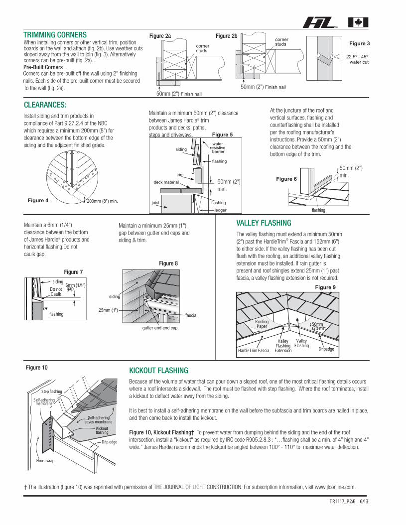
† The illustration (figure 10) was reprinted with permission of THE JOURNAL OF LIGHT CONSTRUCTION. For subscription information, visit www.jlconline.com.
TR1117_P2/6 6/13
Install siding and trim products in compliance of Part 9.27.2.4 of the NBC which requires a minimum 200mm (8") for clearance between the bottom edge of the siding and the adjacent finished grade.
Figure 4 200mm (8") min.
At the juncture of the roof and vertical surfaces, flashing and counterflashing shall be installed per the roofing manufacturer’s instructions. Provide a 50mm (2") clearance between the roofing and the bottom edge of the trim.
50mm (2") min.Figure 6
flashing
Figure 5
Maintain a minimum 50mm (2") clearance between James Hardie® trim products and decks, paths, steps and driveways.
joist
water resistive barriersiding
flashing
deck material
ledger
trim
flashing
siding 6mm (1/4") gap
flashing
Do notCaulk
Figure 7
Maintain a 6mm (1/4") clearance between the bottom of James Hardie® products and horizontal flashing.Do not caulk gap.
Because of the volume of water that can pour down a sloped roof, one of the most critical flashing details occurs where a roof intersects a sidewall. The roof must be flashed with step flashing. Where the roof terminates, install a kickout to deflect water away from the siding.
It is best to install a self-adhering membrane on the wall before the subfascia and trim boards are nailed in place, and then come back to install the kickout.
Figure 10, Kickout Flashing† To prevent water from dumping behind the siding and the end of the roof intersection, install a "kickout" as required by IRC code R905.2.8.3 : “…flashing shall be a min. of 4” high and 4” wide.” James Hardie recommends the kickout be angled between 100° - 110° to maximize water deflection.
Figure 10 KICKOUT FLASHING
Self-adheringmembrane
Step flashing
Housewrap
Drip edge
Kickoutflashing
Self-adheringeaves membrane
Maintain a minimum 25mm (1") gap between gutter end caps and siding & trim.
CLEARANCES:
HardieTrim Fascia DripedgeValley
FlashingExtension
ValleyFlashing
RoofingPaper 50mm
(2") min.
Figure 9
VALLEY FLASHINGThe valley flashing must extend a minimum 50mm (2") past the HardieTrim® Fascia and 152mm (6") to either side. If the valley flashing has been cut flush with the roofing, an additional valley flashing extension must be installed. If rain gutter is present and roof shingles extend 25mm (1") past fascia, a valley flashing extension is not required.
Figure 8
fascia
siding
25mm (1")
gutter and end cap
50mm (2") min.
cornerstuds
Figure 2bFigure 2a
water cut22.5º - 45º
Figure 3TRIMMING CORNERSWhen installing corners or other vertical trim, positionboards on the wall and attach (fig. 2b). Use weather cuts sloped away from the wall to join (fig. 3). Alternatively corners can be pre-built (fig. 2a).Pre-Built CornersCorners can be pre-built off the wall using 2" finishing nails. Each side of the pre-built corner must be secured to the wall (fig. 2a).
50mm (2") Finish nail50mm (2") Finish nail
cornerstuds

TR1117_P3/6 6/13
blocking/supportif required
sheathing
water resistive barrier
A flashing is required over the trim (fig. 13).
lap siding
6mm (1/4") gap
flashing
HardieTrim board
caulk
Figure 13
Do notCaulk
BAND BOARD
water-resistivebarrier
flashing
flashing
406mm (16") o.c. maximum
Figure 11
lapsiding
do not caulk along top edge(refer to fig. 7)
HardieTrim®
board
TRIM APPLICATION FOR WINDOWS, DOORS & OTHER OPENINGS BAND BOARDS, FRIEZE BOARDS, & RAKE TRIM
Trim the opening prior to the installation of the siding (fig. 11)
NOTE: Follow your window/door manufacturersinstallation instructions.
leave a minimum 3mm (1/8") gap, then caulk.
Soffitpanel
2x sub fasciaHardieTrim®
Fascia Board
HardieTrimbandboard
HardieTrimrake trim
flashing
Leave a minimum 3mm (1/8") gap between the siding and trim, then caulk.
HardieTrim® 4/4 and 5/4 Trim may also be used as band boards, frieze boards, or rake trim (fig. 12). For fascia, use HardieTrim® Fascia Boards.
Figure 12HardieTrim
friezeboard
DO NOT USE AS FASCIA

For Corners, Band Boards, Windows, and Door Applications:HardieTrim® boards can be installed with Flat Tabs (JH sku no. 280154) and Corner Tabs (JH sku no. 280155) which provide concealed fastening. Only Flat and Corner Tabs can be used with HardieTrim® boards to create a concealed fastening. Additional framing may be required to ensure the Flat and Corner Tabs are fastened properly to the structure. Special attention should be paid to the framing when using a sheathing that does not have fastener holding equivalent to OSB or Plywood sheathing.
Step 1: Attach Flat Tabs to the back side of the trim with 4 18 ga. 1/2"L x 1/4"W narrow crown corrosion resistant staples, equally spaced in one row, positioned no closer than 1/2" from trim edges, using a pneumatic staple gun. (Figure 19)Step 2: For wood frame construction, attach the trim to the building using 2, 6d siding nails fastened through the Flat Tabs. ET&F or equivalent fasteners may be used to attach the Flat Tabs to steel frame construction. (Figures 20)
Fastener spacing will vary based on application. Refer to specific sections in these instructions for required fastener spacing by application (window, band board, etc.) Refer to fastener table on page 6
Figure 19
TRIMMING CORNERSHardieTrim® boards are installed around corners by pre-building the corner off the wall with the Corner Tabs (JH sku no. 280155). • Attach Corner Tabs to the back side of the trim with 8 18 ga. 1/2"L x 1/4"W narrow crown galvanized staples using a pneumatic staple gun. Ensure the Corner Tabs are fastened tight and straight to the trim boards. (Figure 21) • For wood frame construction, attach the trim to the building with 2, 6d siding nails fastened through the Corner Tabs. ET&F or equivalent fasteners may be used to attach the Corner Tabs to steel frame construction. (Figure 22) • Attach a Corner Tab 1" from each edge and every 20" o.c. • TIP: Creating a jig for the work station is recommended to ensure the corners are fastened securely and straight. (Figure 24)
CONCEALED FASTENING TABS
Fasten 2” x 4”timber blocksto a work benchCorner Tabs
Fasten 2” x 8” studto the timber blocks
HardieTrim®
Figure 21 Figure 22
Use 4 staples per pieceof trim to fasten theL-shaped tab to thepre-built corner. Usethe nail line on thetabs as a guide.
Corner studs
Siding nail Corner Tab
weather cut22.5º - 45º
Figure 23
Figure 24
Figure 20
Flat Tab
use 2, 6dsiding nail orequivalentfastener
Corner Tab
Installation of HardieTrim Tabs over Pressure Treated Lumber:HardieTrim™ tabs shall not come in direct contact with ACQ or CA preservative-treated wood. Refer to the General Fastening section of this document forfurther information.
HardieTrim® NT3™ boards with ColorPlus® TechnologyRemove the laminate sheet as soon as possible after attaching the trim to the building.
Installation of HardieTrim tabs in Coastal Regions:James Hardie requires that stainless steel staples & fasteners be used when installing HardieTrim™ Tabs in coastal regions.
TR1117_P4/6 6/13
HardieTrim™ Flat TabHardieTrim™ Flat Tab
Fasten 4 staples to the center of the nailing ridge. Min 2" Min 1/2"
Figure 26Figure 27
TRIM APPLICATION FOR WINDOWS, DOORS & OTHER OPENINGSTrim the opening prior to the installation of the siding (Figure 26). Place a Flat Tab at the end of each trim board and one tab every 16" OC. Attach the trim boards and Flat Tabs around the opening as shown in Figures 26 and 27. Use 16 ga. galvanized 2" long finish nails to ensure proper fastening if needed.
NOTE: Follow your window/door manufacturersinstallation instructions.
Side trim pieces go tothe top of the window.
Bottom trim pieceis the width of thewindow.
Header piece spans the windowincluding the side trim pieces.

* Refer to your paint manufacturer for washing and recoating requirements related to paint performance.
Flashing needs to betucked under the waterresistive barrier and overthe Flat Tabs.
Water-resistive Barrier 1/4" gap
Do not caulk between thesiding and the flashing.
1/8" caulked gap is left betweensiding and the side trim pieces.
Figure 28
Figure 30
Figure 31
Flat Tabs
Caulk
HardieTrim® boards
Flashing
1/4" gap. Do not caulk.
HardiePlank® Lap Siding
Weather-resistive barrier
Sheathing
Fasten 4 staples to the tab as shown.Flat Tabs
16" o.c. max
Blocking
Flat Tabs
16" o.c. max
Do not under
drive nails.
Flat and Corner Tabs
Flat andCorner Tabs
Only use staples tofasten Flat and Corner Tabs to the trim boards.
Siding nailattaches tabto the wall.
FlushFigure 32
Figure 29
TR1117_P5/6 6/13
BAND BOARDA flashing is required over the trim and Flat Tabs. (Figure 29) Terminate ends of theBand Board into Trim or Siding or miter cut the edges of the trim at the corners of the building. Place a Flat Tab at the end of each trim board and one tab every stud at a maximum of 16" o.c. The Flat Tabs should be attached to the trim in an alternating pattern to the top and bottom of the band board (Figure 30 and 31).
GENERAL FASTENING REQUIREMENTSFasteners must be corrosion resistant, galvanized, or stainless steel. Electro-galvanized are acceptable but may exhibit premature corrosion. James Hardie recommends the use of quality, hot-dipped galvanized nails. James Hardie is not responsible for the corrosion resistance of fasteners. James Hardie recommends using stainless steel fasteners when installing James Hardie® products near the ocean, large bodies of water, or in humid climates.
Manufacturers of ACQ and CA preservative-treated wood recommend spacer materials or other physical barriers to prevent direct contact of ACQ or CA preservative-treated wood and aluminum products. Fasteners used to attach HardieTrim Tabs to preservative-treated wood shall be of hot dipped zinc-coated galvanized steel or stainless steel and in accordance to 2009 IRC R317.3 or 2009 IBC 2304.9.5.”
• Drive fasteners perpendicular to the trim and framing.• Do not drive nails at an angle.• For wood framing, under driven nails should be hit flush to the trim with a hammer (for steel framing, remove and replace nail).• Do not use aluminum fasteners, staples, or clipped head nails.
do not under
drive nails Figure AFinish Nail
Flush
PNEUMATIC FASTENING:HardieTrim® boards can be hand nailed or fastened with a pneumatic tool. Pneumatic fastening is highly recommended. Finish nails should be driven flush to the trim (fig. A). A flush mount attachment on the pneumatic tool is recommended. This will help control the depth the nail is driven. If setting the nail depth proves difficult, choose a setting that under drives the nail. (Drive under driven nails snug with a smooth faced hammer - Does not apply for installation to steel framing).

Additional Installation Information, Warranties, and Warnings are available at
www.jameshardie.com
TR1117_P6/6 6/13
CAULKING
PAINTINGDO NOT use stain, oil/alkyd base paint, or powder coating on James Hardie® Products. James Hardie products must be painted within 180 days for primed product and 90 days for unprimed.100% acrylic topcoats are recommended. Do not paint when wet. For application rates refer to paint manufacturers specifications. Back-rolling is recommended if the siding is sprayed.
• Care should be taken when handling and cutting James Hardie ColorPlus products. During installation use a wet soft cloth or soft brush to gently wipe off any residue or construction dust left on the product, then rinse with a garden hose.• Touch up nicks, scrapes and nail heads using the ColorPlus® Technology touch-up applicator. Touch-up should be used sparingly. If large areas require touch-up, replace the damaged area with new HardieTrim® board with ColorPlus Technology.• Laminate sheet must be removed immediately after installation of each trim board.• Terminate non-factory cut edges into trim where possible, and caulk. Color matched caulks are available from your ColorPlus® product dealer.• Treat all other non-factory cut edges using the ColorPlus Technology edge coaters, available from your ColorPlus product dealer.
COLORPLUS® TECHNOLOGY CAULKING, TOUCH-UP & LAMINATE
PAINTING JAMES HARDIE® SIDING AND TRIM PRODUCTS WITH COLORPLUS® TECHNOLOGYWhen repainting ColorPlus® products, James Hardie recommends the following regarding surface preparation and topcoat application: • Ensure the surface is clean, dry, and free of any dust, dirt, or mildew • Repriming is normally not necessary • 100% acrylic topcoats are recommended • DO NOT use stain, oil/alkyd base paint, or powder coating on James Hardie® Products. • Apply finish coat in accordance with paint manufacturers written instructions regarding coverage, application methods, and application temperature • DO NOT caulk nail heads when using ColorPlus products, refer to the ColorPlus touch-up section
CUT EDGE TREATMENT
Elastomeric Joint Sealant is required in accordance with Part 9.27.4 of the NBC, complying with ASTM C920 Grade NS, Class 25 or higher or a Latex Joint Sealant complying with ASTM C834. Caulking/Sealant must be applied in accordance with the caulking/sealant manufacturer’s written instructions. Note: OSI Quad as well as some other caulking manufacturers do not allow tooling.DO NOT caulk nail heads when using ColorPlus products, refer to the ColorPlus touch-up section
FASTENER TABLE Application Framing MaterialTab is nailed into
Flat Tab
Wood Stud(minimum G=0.42)
Minimum APA rated7/16" OSB
Corner TabMinimum APA rated
7/16" OSB
Minimum 20gauge steel
Minimum 20gauge steel
Wood Stud(minimum G=0.42)
Fastener(tab to NT3 trim)
Max Tab Spacing(inches on center)
Four 18 ga. X 1/2" long X 1/4" wide
corrosion resistant crown staples,
equally spaced in one row
16
For each piece of trim, install Four 18 ga. X 1/2" long X
1/4" wide corrosion resistant crown staples, equally
space in two rows
20
Fastener(tab to framing)
One 6d corrosion resistant siding nailinstalled through center of flange into framing
Two 4d ring shank corrosion resistantsiding nails equally spaced installed
through flange into framing
One No. 8 X 1" long X 0.323" headdiameter screw (corrosion resistant)installed through flange into framing
On each flange, Install one 6dcorrosion resistant siding nail through
flange into framing
On each flange, Install two 4d ringshank corrosion resistant siding nails
through flange into framing
On each flange, Install one No. 8 X 1"long X 0.323" head diameter screw
(corrosion resistant) through flange into framing
Wind-Borne Debris Region: “Supplemental fasteners may be necessary when installing tabs in a Wind-Borne Debris Region, please call Technical Services 800-942-7343 with any questions.”
© 2013 James Hardie Building Products. All rights reserved.TM, SM, and ® denote trademarks or registered trademarks of James Hardie Technology Limited. is a registered trademark of James Hardie Technology Limited.
Caulk, paint or prime all field cut edges. James Hardie touch-up kits are required to touch-up ColorPlus products.
Note: James Hardie does not warrant the usage of third party touch-up or paints used as touch-up on James Hardie ColorPlus products.
Problems with appearance or performance arising from use of third party touch-up paints or paints used as touch-up that are not James Hardie touch-up, will not be covered under the James Hardie ColorPlus Limited Finish Warranty.
RECOGNITION: HardieTrim boards may be installed as an equal alternative to conventional trim permitted for use in; 2006, 2009, & 2012 International Building Code, Section 1402.1, and the 2006, 2009, & 2012 International Residence Code for One - and Two - Family - Dwellings, Section R703.1.

Site Address:
Client:
Architect:
Drawing Title:
Drawn By: Date:
Sheet Number:
Project:
Midland panel trim
Profile sheet 1
LC Jan.24/19
D-1.1
#15/8"
2"
2"
5/8"
1/2"
1/2"
Panel Outside Corner
#2 5/8"
1 1/
2"
1 1/2"
1/2"
5/8"
1/2"
Panel Inside Corner
#3
5/8"
1 5/
8"
1/2"
Panel J trim
#4
1 5/
8"
5/8"
1/2"
Panel Horizontal Z
*Colors To Chosen in Cascadia tomatch JH Panel Colors*
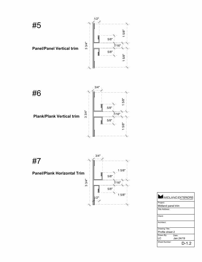
Site Address:
Client:
Architect:
Drawing Title:
Drawn By: Date:
Sheet Number:
Project:
Midland panel trim
Profile sheet 2
LC Jan.24/19
D-1.2
#5
Panel/Panel Vertical trim 3 3/
4"
1/2"
5/8"
7/16"
5/8"
1 5/
8"1
5/8"
#7Panel/Plank Horizontal Trim
3 3/
4"
3/4"
5/8"
7/16"
5/8"
1 5/8"
1 5/8"1/2"
#6
Plank/Plank Vertical trim 3 3/
4"3/4"
5/8"
7/16"
5/8"1
5/8"
1 5/
8"

Site Address:
Client:
Architect:
Drawing Title:
Drawn By: Date:
Sheet Number:
Project:
Midland panel trim
Profile sheet 3
LC Jan.24/19
D-1.3
5/8"3/4"
5/8"
3/4"
2"
2"
#8
Plank Outside Corner
#9
Plank Inside Corner
3/4" 5/8"
3/4"
5/8"
1 1/2"
1 1/
2"
#10
Plank J trim
1 5/
8"
3/4"
5/8"
#11
Plank Horizontal Z
1 5/
8"
5/8"
3/4"

Site Address:
Client:
Architect:
Drawing Title:
Drawn By: Date:
Sheet Number:
Project:
Midland panel trim
Profile sheet 4
LC Jan.24/19
D-1.4
5/8"3/4"
5/8"
1/2"
2"
2"
#12
Plank/Panel Outside Corner
#13
Plank/panel Inside Corner
3/4" 5/8"
1/2"
5/8"
1 1/2"
1 1/
2"

Prepainted Steel Color Selection Guide
SMP (Silicon Modified Polyester) Standard Colors
SMP pre-painted steel is a high quality painted steel product with many uses in the building trades, has a life expectancy of 30+ years, and is available with our in-house warranty.
Polar WhiteQC1820 - R
Cambridge WhiteQC3695
White WhiteQC8317
Bone WhiteQC8273
Surf WhiteQC8316
Regent GrayQC1730
Stone GrayQC8305
CharcoalQC8306
Metro BrownQC8228
Coffee BrownQC8326
Dark BrownQC8229
BlackQC8262
TanQC8315
BriarwoodQC833
Antique LinenQC3696
GoldQC8276
Sapphire BlueQC8261
Slate BlueQC8260
Heron BlueQC8330
Labrador BlueQC3688
Royal BlueQC8790
Bright RedQC8386
Dark RedQC8250
Tile RedQC8259
Melchers GreenQC8307
Forest GreenQC8329
Spruce GreenQC3697
Sage GreenQC6089
Mist GreenQC8256
Deep Water GreenQC3684
Cabec GreenQC2166
TurquoiseQC8310
Pacific TurquoiseQC8258

1. Based on ASTM A 653M Grade 230 structural steel.2. Values in row “S” are based on strength.3. Values in row “D” are based on de!ection of 1/180th span.4. Web crippling not included in strength calculations. See Example. Limit States Design principles were used in accordance with CSA Standard S136-01 Load table prepared by Dr. R.M.Schuster P.Eng. University of Waterloo, Ontario, Canada.
IMPERIAL
All dimensions are in inches.
SECTION PROPERTIES (Per Foot of Width)
Base SteelThickness
(in.)
Coated SteelThickness
(G90)(in.)
CoatedWeight
(psf )
Sec. ModulusMidspan Support De!ection
Moment ofInertia(in.4)
Speci"ed Web Crippling Data
Pe1
End(lb)
Pe2
End(lb)
Pi1
Interior(lb)
Pi2
Interior(lb)
MAXIMUM UNIFORMLY DISTRIBUTED SPECIFIED LOAD (psf)SPAN
LENGTH(ft)
1 - SPANBASE STEEL THICKNESS (inches)
2 - SPANBASE STEEL THICKNESS (inches)
3 - SPANBASE STEEL THICKNESS (inches)
0.018 0.024 0.030 0.036 0.018 0.024 0.030 0.036 0.018 0.024 0.030 0.036 3.0 S 36 56 80 100 60 79 97 115 56 88 121 144 D 99 147 205 269 238 352 492 645 188 278 388 508 3.5 S 26 41 59 74 44 58 71 85 41 64 89 106 D 62 92 129 169 150 222 310 406 118 175 244 320 4.0 S 20 32 45 56 34 44 55 65 31 49 68 81 D 42 62 87 113 100 149 208 272 79 117 164 214 4.5 S 16 25 36 45 27 35 43 51 25 39 54 64 D 29 44 61 80 71 104 146 191 56 82 115 151 5.0 S 13 20 29 36 22 28 35 41 20 32 44 52 D 21 32 44 58 51 76 106 139 41 60 84 110 5.5 S 11 17 24 30 18 23 29 34 17 26 36 43 D 16 24 33 44 39 57 80 105 30 45 63 82 6.0 S 9 14 20 25 15 20 24 29 14 22 30 36 D 12 18 26 34 30 44 62 81 23 35 48 64 6.5 S 8 12 17 21 13 17 21 25 12 19 26 31 D 10 14 20 26 23 35 48 63 18 27 38 50 7.0 S 7 10 15 18 11 14 18 21 10 16 22 26 D 8 12 16 21 19 28 39 51 15 22 31 40 7.5 S 6 9 13 16 10 13 16 18 9 14 19 23 D 6 9 13 17 15 23 32 41 12 18 25 33 8.0 S 5 8 11 14 8 11 14 16 8 12 17 20 D 5 8 11 14 13 19 26 34 10 15 20 27 8.5 S 4 7 10 12 7 10 12 14 7 11 15 18 D 4 6 9 12 10 15 22 28 8 12 17 22 9.0 S 4 6 9 11 7 9 11 13 6 10 13 16 D 4 5 8 10 9 13 18 24 7 10 14 19 9.5 S 4 6 8 10 6 8 10 11 6 9 12 14 D 3 5 6 8 7 11 16 20 6 9 12 16 10.0 S 3 5 7 9 5 7 9 10 5 8 11 13 D 3 4 6 7 6 10 13 17 5 7 10 14
NOTES:
0.0180 0.0195 1.04 0.0243 0.0408 0.0154 69.8 17.4 132 22.5 0.0240 0.0255 1.36 0.0382 0.0537 0.0227 128 32.1 243 41.3 0.0300 0.0315 1.69 0.0547 0.0663 0.0317 205 51.3 388 66.0 0.0360 0.0375 2.02 0.0684 0.0785 0.0416 301 75.2 568 96.5
(in.3) (in.3)
126
1.00Rib Spacing Options Available*
WF HF 12
- Denotes Colored Side
* Rib spacing of 4”, 6” or fully striated available.

1. Based on ASTM A 653M Grade 230 structural steel.2. Values in row “S” are based on strength.3. Values in row “D” are based on de!ection of 1/180th span.4. Web crippling not included in strength calculations. See Example. Limit States Design principles were used in accordance with CSA Standard S136-01 Load table prepared by Dr. R.M.Schuster P.Eng. University of Waterloo, Ontario, Canada.
METRIC
SECTION PROPERTIES (Per Metre of Width)
Base SteelThickness
(mm)
Coated SteelThickness
(Z275)(mm)
CoatedMass
(kg/m2)
Sec. ModulusMidspan Support De!ection
Moment ofInertia
(106mm4)
Speci"ed Web Crippling Data
Pe1
End(kN)
Pe2
End(kN)
Pi1
Interior(kN)
Pi2
Interior(kN)
MAXIMUM UNIFORMLY DISTRIBUTED SPECIFIED LOAD (kPa)SPAN
LENGTH(m)
1 - SPANBASE STEEL THICKNESS (mm)
2 - SPANBASE STEEL THICKNESS (mm)
3 - SPANBASE STEEL THICKNESS (mm)
0.457 0.610 0.762 0.914 0.457 0.610 0.762 0.914 0.457 0.610 0.762 0.914 1.0 S 1.44 2.26 3.23 4.05 2.42 3.19 3.93 4.66 2.25 3.53 4.92 5.82 D 3.62 5.36 7.49 9.81 8.70 12.9 18.0 23.6 6.85 10.1 14.2 18.5 1.2 S 1.00 1.57 2.25 2.81 1.68 2.21 2.73 3.23 1.56 2.45 3.41 4.04 D 2.10 3.10 4.33 5.68 5.03 7.45 10.4 13.6 3.96 5.87 8.19 10.7 1.4 S 0.73 1.15 1.65 2.07 1.24 1.63 2.01 2.38 1.15 1.80 2.51 2.97 D 1.32 1.95 2.73 3.58 3.17 4.69 6.55 8.58 2.50 3.69 5.16 6.76 1.6 S 0.56 0.88 1.26 1.58 0.95 1.25 1.54 1.82 0.88 1.38 1.92 2.27 D 0.88 1.31 1.83 2.40 2.12 3.14 4.39 5.75 1.67 2.48 3.45 4.53 1.8 S 0.44 0.70 1.00 1.25 0.75 0.98 1.21 1.44 0.69 1.09 1.52 1.80 D 0.62 0.92 1.28 1.68 1.49 2.21 3.08 4.04 1.17 1.74 2.43 3.18 2.0 S 0.36 0.56 0.81 1.01 0.61 0.80 0.98 1.16 0.56 0.88 1.23 1.46 D 0.45 0.67 0.94 1.23 1.09 1.61 2.25 2.94 0.86 1.27 1.77 2.32 2.2 S 0.30 0.47 0.67 0.84 0.50 0.66 0.81 0.96 0.46 0.73 1.02 1.20 D 0.34 0.50 0.70 0.92 0.82 1.21 1.69 2.21 0.64 0.95 1.33 1.74 2.4 S 0.25 0.39 0.56 0.70 0.42 0.55 0.68 0.81 0.39 0.61 0.85 1.01 D 0.26 0.39 0.54 0.71 0.63 0.93 1.30 1.70 0.50 0.73 1.02 1.34 2.6 S 0.21 0.33 0.48 0.60 0.36 0.47 0.58 0.69 0.33 0.52 0.73 0.86 D 0.21 0.31 0.43 0.56 0.49 0.73 1.02 1.34 0.39 0.58 0.80 1.06 2.8 S 0.18 0.29 0.41 0.52 0.31 0.41 0.50 0.59 0.29 0.45 0.63 0.74 D 0.17 0.24 0.34 0.45 0.40 0.59 0.82 1.07 0.31 0.46 0.64 0.84 3.0 S 0.16 0.25 0.36 0.45 0.27 0.35 0.44 0.52 0.25 0.39 0.55 0.65 D 0.13 0.20 0.28 0.36 0.32 0.48 0.67 0.87 0.25 0.38 0.52 0.69
NOTES:
0.457 0.497 5.06 1.30 2.19 0.0209 0.560 0.392 1.95 0.331 0.610 0.650 6.66 2.05 2.89 0.0310 1.09 0.761 3.58 0.609 0.762 0.802 8.25 2.93 3.56 0.0432 1.80 1.26 5.72 0.973 0.914 0.954 9.85 3.67 4.22 0.0566 2.70 1.89 8.38 1.42
(103
mm3)(103
mm3)
305152
25.4Rib Spacing Options Available*All dimensions are in millimeters.
WF HF 12
- Denotes Colored Side
* Rib spacing of 101mm, 152mm or fully striated available.


July 13, 2015
RE: Dymonic FC- Green Building Product Information (LEED® Information)
Tremco, as an organization, is committed to quality, responsive to both internal and external customers, our employees, our community and environment, and we will treat all with respect and good stewardship.
Tremco Inc. certifies the following information for Dymonic FC
Regional Materials: Dymonic FC is manufactured in Toronto, Ontario, Canada.
No single extracted material is used to produce the majority of this product. Additionally, all raw materials come from one of several sources which in turn come from one of several raw material feed stocks. As such, point source for the raw materials cannot be determined.
Recycled Content Information: Recycled content for Dymonic FC is not available, and for the purposes of LEED reporting should be assumed to be zero.
VOC Content Information: Dymonic FC has a VOC content of 6g/l equaling 0.39% by weight as applied/mixed.
Note: VOC content values are as reported for the highest VOC content color for all Dymonic FC colors. Other colors may have a lower VOC content reported on their MSDS.
Additional Information:
Should you have any questions or require additional information, please do not hesitate to contact Technical Services or your local Tremco Field Representative.
Sincerely,
Amy Woodard Manager Compliance and Regulatory
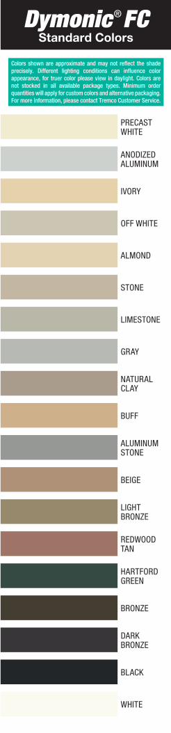
Dymonic® FCStandard Colors
Colors shown are approximate and may not reflect the shade precisely. Different lighting conditions can influence color appearance, for truer color please view in daylight. Colors are not stocked in all available package types. Minimum order quantities will apply for custom colors and alternative packaging. For more information, please contact Tremco Customer Service.
ALMOND
ALUMINUMSTONE
ANODIZEDALUMINUM
BEIGE
BLACK
BRONZE
BUFF
DARKBRONZE
GRAY
HARTFORDGREEN
IVORY
LIMESTONE
NATURALCLAY
OFF WHITE
PRECASTWHITE
REDWOODTAN
STONE
WHITE
LIGHTBRONZE

Dymonic
® FC
Dymonic
® FCH
igh
-Perfo
rman
ce, Fast-Cu
ring
, Sin
gle-C
om
po
nen
t, Hyb
rid S
ealant
Dym
on
ic® FC
is a hig
h-p
erform
ance, fast-cu
ring
, sing
le-co
mp
on
ent, lo
w m
od
ulu
s, hyb
rid sealan
t form
ulated
with
pro
prietary silan
e end
-capp
ed p
olym
er techn
olo
gy.
Ap
plicab
le Stan
dard
sA
STM C
920 Type S, G
rade N
S, Class 35, U
se NT, M
, A an
d O
; ASTM
C 124
8; C
AN
/CG
SB-19.13
-M87;
U.S. Fed
eral Specifi
cation
TT-S-0
0230C
, Class A
, Type II;
Meets A
AM
A 8
08
.3-10
; UL 2079 (A
STME 19
66), C
AN
-4-S115M
.
Tremco
Co
mm
ercial Sealan
ts & W
aterpro
ofi
ng
3735 Green
Ro
ad, B
eachw
oo
d, O
H 44122 // Ph
on
e: 216.292.5000 // 800.321.7906220 W
icksteed A
venu
e, Toro
nto
, ON
M4H
1G7 // Ph
on
e: 416.421.3300 // 800.363.32131451 Jaco
bso
n A
venu
e, Ash
land
, OH
44805 // Pho
ne: 419.289.2050 // 800.321.6457
1117/DFC
SD