dredging and reclamation in makassar port development ... · dredging and reclamation in makassar...
TRANSCRIPT
SESSION IV : Amérmgement et protection du litwral
Dredging and Reclamation in MakassarPort Development Project
Sumardi
Managing Director of PT. (Persero) Pelabuhan Indonesia IVWahyono Bimarso
Technical Director of PT. (Persero) Pelabuhan Indonesia IVEdy D.M. Nursewan
Sub Directorate of Port Facilities of PT. (Persero) PelabuhanIndonesia IV
Abstract
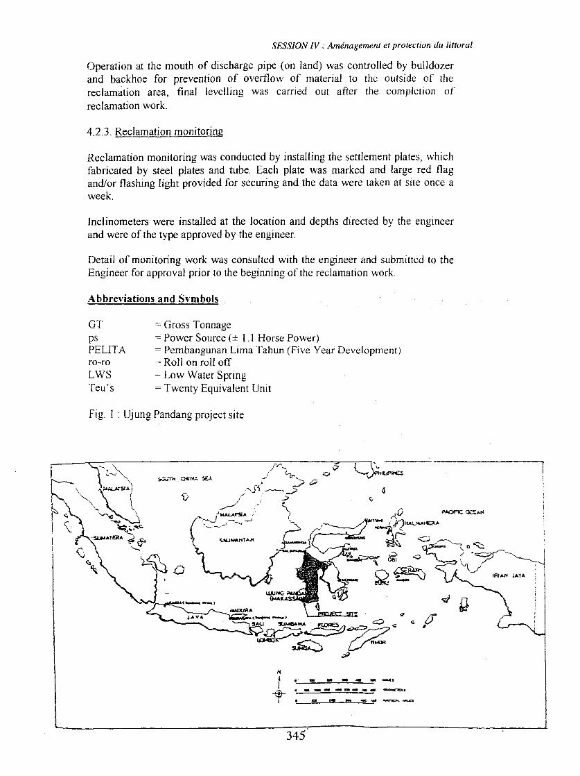
Makassar port was nominated as one .of the four gateways ports of Indonesia,which covers the provinces of East Kalimantan, Sulawesi, Maluku, and Irian Jaya.Thus, the government of indonesia intend to deve10p this port by constructing anew wharf, including dredging and reclamation works. The dredging work underthe project was to remove very soft marine deposit lying widely in the project siteapproximately up ta -20 meters, which was unsuitable for foundation of thewharfs structures, and all the dredged materials were transported and disposed atthe designated offshore dumping site. Except sand replacement area reclamationwork was performed directly on the extremely soft marine clay of 8 metersthickness, and total rec1amationheight ""vasabout 17 meters above the soft clay.
Résumé
Le port de MACASSAR a été retenu comme l'un des quatre ports d'entreé enIndonésie. Il dessert la province de Bornéo est et les iles Celebes, les ilesMouluque et la Nouvelle Guinée ouest. L'Indonésie a l'intention de le développeren le dotant de nouveaux appontements, qui nécessitent des travaux de dragage etd'assèchement conséquents. Les dragages nécessaires au projet consistaient àenlever des sédiments marins de consistance très molle. Ceci interesse toutel'étendue d'implantation du site projeté, jusqu'à la cote - 20 mètres. Ceci neconvenaient pas pour les fondations de la structure des appontements. Lesmatériaux ainsi dragués étaient transportés et mis en dépôts sur un site d'accueiloffshore.
Sauf pour les travaux d'assèchement de la zone où le sable est substitué qui sontréalisés directement sur la couche d'argille molle de 7 mètres, la hauteurnécessaires aux travaux d'assèchement étaient du 17 mètres au-dessus de la
couche d'argile.
1. General description of port of makassar
Port of Makassar located in th.e province of South Sulawesi, is the main portunder the authority of The indonesian port corporation IV. It is located between05° 08'08" Sand 119° 24'02" E. From domestic shipping line point ofview, tbisÎs a very strategie location because it connects the western and the eastern part ofIndonesia, while for outbound shipping line it will be quite prospective in the
337
SESSION IV : Aménagement et protection du littoral
future time since it is 10cated in the south end of Makassar Strait which is one
option for international ships sailing through it. (Figure 1).
Most of hinterland potential is still dominated by agricultural and wood products,yet in last several industrial sector was spurred through the existence of Makassarindustrial zone (KIMA) and processing industries in sorne regencies in SouthSulawesi. Riee, corn, beans, rattan, cocoa, floU! are sorne of inter-islandeommodities move through Port of Makassar. Cocoa, sea product, plywood andcashew nuts are the dominant commodities directly exported to Japan, Singapore,China, Korea and India.
To antieipate increasing cargo loading and uruoading volume in the port,especially containers it is necessary to keep improving port of Makassar' sfacilities and infrastructures. Currently, the port is being developed byconstruction of a 850 m full-container berth with container yard and its facilities,which is funded by OECF Japan. The project has been completed in October 1997which can accommodate approximately 360,000 Teu' s of containers.
The Ïncrease of development aetivities witnout eonsidering rneticulouslyenvirornnental factors will induce cistly risk or darnages to the enviTûï.ul1ent.Imbala.-TIces in one or several envÏTon.mental components may obstruer theecosystem function entirely. Therefore the construction should be carried outjudiciously in example by considering ecological prineiples and should beenvironmental concept.
The environmental concept development is expected not only beneficial at thismoment, but also for the next future. Rence the expected development is asustainable âlld harmonious development. The discretion of environmentalconcept development has been covered in the guidelines of state poliey, it isstated that in the development, we expect that there will be a harmoniousrelationship between human and his environment. Studies of Port of Makassarconceming preliminary studies, environmental impact assessment, environmentalimpact management plan, environmental impact monitoring plan andenvironmental survey have been conducted in effort to cater the provisions ofenvirornnentaI Iaws and to achieve the environmental concept developrnent
2. Description of port of makassar activity
2.1. General Condition
2.1.1. Port working and interest area
Port of Makassar is supported by availability of land and waterways areadetermÏned by the decision of South Sulawesi Governor no.27/KPPSMIIIBKP1'vID/93, stated that the waterways area of Port of Makassaris 1,467.20 ha and the working area of Port of Makassar is 50.78 ha.
Port of Makassar consist of three quays, Soekarno Quay for generaI cargo, bulkcargo, multi purpose and passenger terminal, Hatta Quay for container and multi
338
-12 LWS+3.5MLWS360m
SESSIONN : Aménagement et protection du littoral
purpose terminal ( began in the middle of the year 1997), and local and traditional.vessels are handled at Paotere Quay.
Also sorne industries are instaUed within port area, such as :
a. Tonasa Packing Plant, having 4 silos each of which 6,000 ton capacity. Theproduction is expected to reach 6,000 tons/year in the middle of the year 1997.
b. Pertamina Oil Terminal, which is supplies the need of oil in South Sulawesi.c. Berdikari Flour Mill, to fulfil the domestic and export of flour that reach
175.000 tons/year.
2.1.2. Port facilities
The intensity of activity and capacity of port services will greatly be influencedby the condition of facilities owned by the port. The following tables contain theavailable facilities in the port of Makassar.
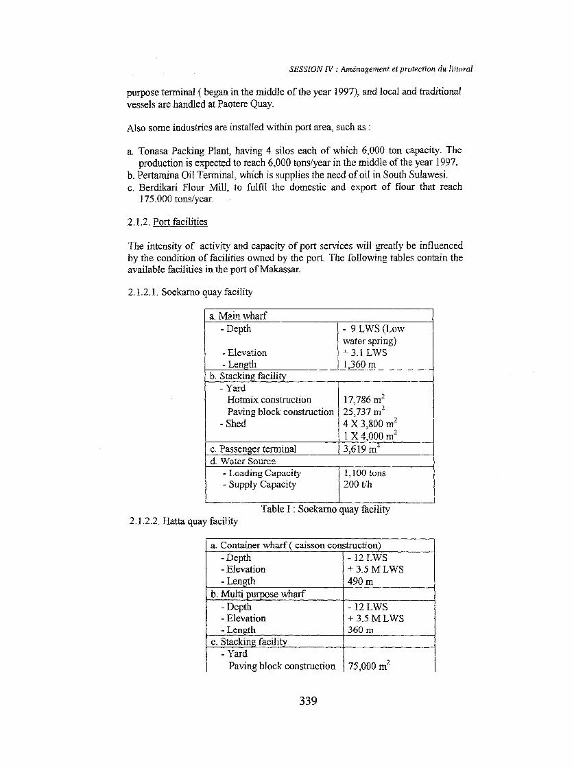
2.1.2.1. Soekarno quay facility
a. Main wharf- Depth
- 9 LWS (Lowwater spring)- Elevation
+ 3.1 LWS- Length
1,360 mb. Stacking facilitv - YardHotrnix construction
17,786 m2
1Paving block construction
25,737 ml- Shed
4 X 3,800 ml1 X 4,000 m2c. Passenger terminal
3,619 m~d. Water Source - Loading Capacity
1,100 tons- Supply Capacity
200 t/h
j
Table 1 : Soekarno quay facility2.1.2.2. Hatta quay îacility
a. Container wharf ( caisson construction)- Depth - 12 LWS- Elevation + 3.5 ML WS-Len 490m
b. Multi se wharf
-Depth- Elevation- Len h
c. Stackin facili- Yard
Paving block construction 75,000 ml
339
SESSION N :Aménagement et protection du littoral
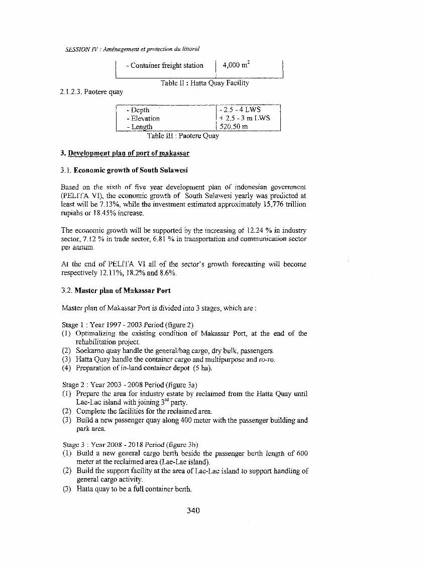
- Container freight station \ 4,000 m2
Table II : Hatta Quay Facility2.1.2.3. Paotere quay
- 2.5 -4 LWS+ 25 -3 mLWS52050 m
Table ID : Paotere Quay
- Depth- Elevation- Len
3. Development plan of port of makassar
3.1. Economie growth of South Sulawesi
Based on the sixth of five year development plan of indonesian government(PELIT A VI), the economic gro'vvth of South Sulawesi yearly was predicted atleast will be 7.13%, while the investment estimated appfûximately 15,776 trillionrupiahs or 18.45% increase.
The economic gfûwth will be supported by the increasing of 12.24 % in industrysector, 7.12 % in trade sector, 6.81 % in transportation and communication sectorperannuill.
At the end of PELIT A VI aH of the secror' s growth forecasting will becomerespectively 12.11%,18.2% and 8.6%.
3.2. Master plan of Makassar Port
Master plan of Makassar Port is divided into 3 stages, which are:
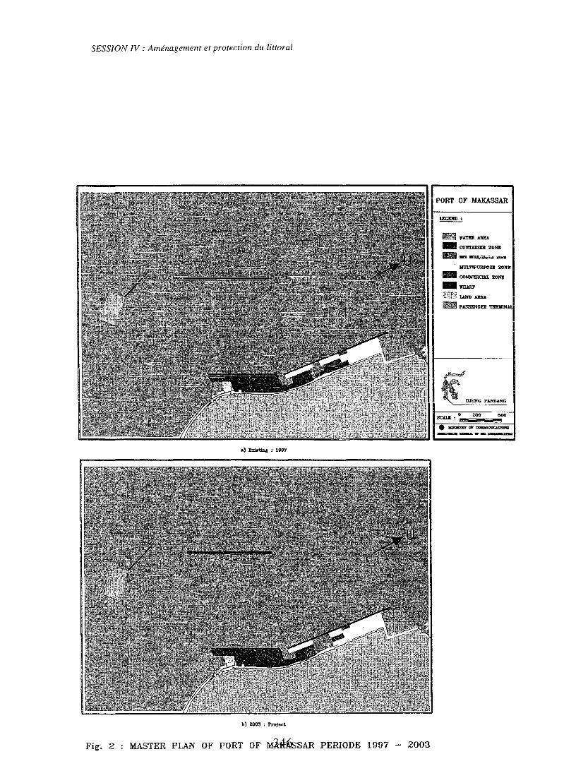
Stage 1 : Year 1997 - 2003 Period (figure 2)(1) Optimalizing the existing condition of Makassar Port, at the end of the
rehabilitation project.(2) Soekarno quay handle the generallbag cargo, dry bulk, passengers.(3) Hatta Quay handle the container cargo and multipurpose and ro-w.(4) Preparation ofin-land container depot (5 ha).
Stage 2 : Year 2003 - 2008 Period (figure 3a)(1) Prepare the area for industry estate by reclaimed from the Hatta Quay until
Lae-Lae Island withjoining 3rd party.(2) Complete the facilities for the reclaÏmed area.(3) Build a new passenger quay along 400 meter with the passenger building and
park area
Stage 3 : Year 2008 - 2018 Period (figure 3b)(1) Build a new general cargo berth beside the passenger berth length of 600
meter at the reclaimed area (Lae-Lae island).(2) Build the support facility at the area of Lae-Lae Island to support handling of
general cargo activity.(3) Hatta quay to be a full container berth.
340
SESSION N : Aménagement et protection du liu"ral
4. Makassar port development project
4. L Seope ofthe work.
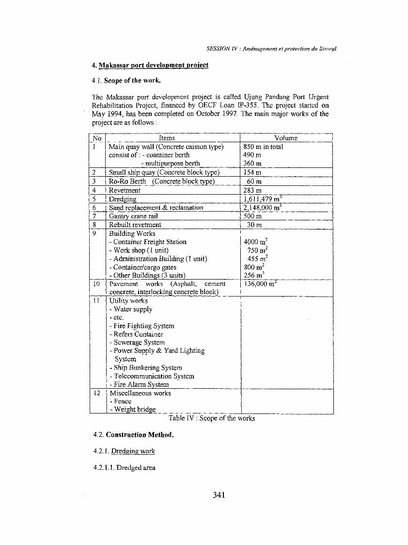
The Makassar port development project is called Ujung Pandang Port UrgentRehabilitation Project, financed by OECF Loan IP-355. The project started onMay 1994, has been completed on October 1997. The main major works of theproject are as follows :
No Itenis
1 Main quay wall (Concrete caisson type)consist of: - container berth
- multi u ose berth
2 Small shi ua Concrete block3 Ro-Ro Berth Concrete block4 Revetment5 Dred'n6 Sand re lacement & reclamation7 Gan crane rail8 Rebuilt revetment
9 Building Works- Container Freight Station- Work shop CI unit)- Administration Building ( 1 unit)- Container/cargo gates- Other Buildin s 3 units
10 Pavement works (Asphalt, cementconcrete, interlockin concrete block
Il Utility works- Water supply- etc.
- Fire Fighting System- Refers Container
- Sewerage System
,- Power Supply & Yard LightingSystem
1 - Ship Bunkering System- Telecommunication System- Fife Alann S stem
12 Miscellaneous works- Fence- Wei ht brid e
Volume850 m in total490m360m154m60m
283 m1,611,479 fi2,148,000 m500m30m
4000 m2
750 m2455 m2
800 m2256 ml136,000 fi
Table IV: Scope of the works
4.2. Construction Method.
4.2.1. Dredging work
4.2.1.1. Dredged area
341
SESSION IV: Aménagement et protection du littoral
Dredged area in the project are small ship Quay, ro-TOberth, main Quay wall,caisson foundation (trench for transition rubble and sand replacement) andrec1amation area.
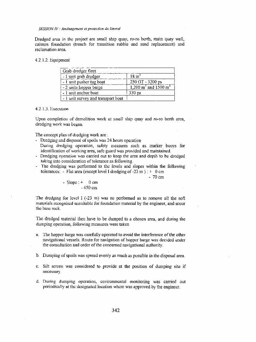
4.2.1.2. Equipment
- 1 unit anchor boat
1 - 1 unit survey and transport boat
4.2.1.3. Execution
Upon compIetion of demolition work at small ship Quay and TO-roberth area,dredging work was began. .
The concept plan of dredging work are:- D:::edgingand disposa] of spoils was 24 hours operation
DÜTill':g dredging operation, safety measures such as marker buoys foridentification of working area, safe guard was provided and maintained.Dredging operation was carried out to keep the area and depth to be dredgedtaking into consideration oftolerance as following.The dredging was perfonned to the levels and slopes within the followingtolerances: - Flat area (except level l dredging of -23 m ) : + 0 cm
- 70 cm
- Slope: + 0 cm- 450 cm
The dredging for leve1 l (-23 m) was so performed as to remove aIl the softmateriaIs recognised unsuitable for foundation material by the engineer, and scourthe base rock.
The dredged material then have to be dumped to a chosen area, and during thedumping operation, following measures were taken
a. The hopper barge was carefully operated to avoid the interference of the othernavigational vessels. Route for navigation of hopper barge was decided underthe consultation and order of the coneemed navigationaI authority.
b. Dumping of spoiIs was spread evenly as mueh as possible in the disposaI area.
e. SiIt screen was eonsidered to provide at the position of dumping site ifnecessary.
d. During dumping operation, environmental monitoring was carried outperiodically at the designated location where was approved by the engineer.
342
SESSION IV : Aménagement et protection du li:wral
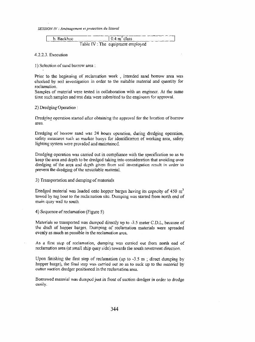
4.2.2. Reclamation Work
Reclamation work began after partially completion of dredging for small shipquay, ro-ro berth, and main quay wall, approx. 100 meters. North end of mainquay wall was the first location and the work was towards to southem direction.
4.2.2.1. Sequence of Reclamation work:
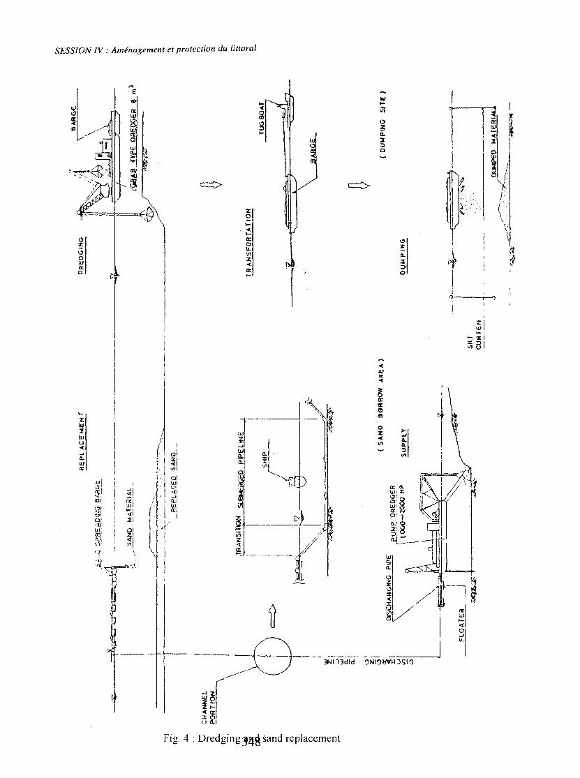
After being taken from a proposed sand bOITOWarea, the work then was dividedinto 3 major components which related to the other works such as dredging,transition rubble and main quay wall.
1) Ist step is following the sand replacement. Reclamation was carried out untilcertain level where level was determined by monitoring of sand shape afterdumping to avoid any disturbance for backfilling and dredging.
2) 2nd step is after completion of backfilling, reclamation up to -3.5 m(determined by draft of hopper barge) was carried out.
3) 3rd step is from -3.5 m to finallevel was reclaimed by micro cutter suctiondredger which handle the reclamation sand done by the second step. TheIl,finallevelling was carried out (figure 4).
The following sequence was taken for reclamation work :
Selection of sand bOITOWarea, soil investigation, sand material, transportation ofborrO\,vedsand, dumping borrowed sand to reclaimed area, direct dumping byhopper barge (dumping up to -3.5 m LWS), and suck up material by suctiondredger (temporarily dumped in front of dredger, and reclaimed from -3.5 m tofinal)
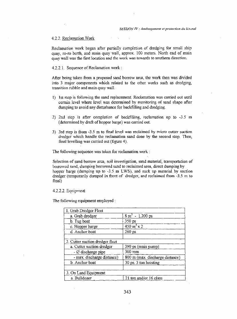
4.2.2.2. Equipment
The foUowingequipment employed :
3. On Land E ui menta. Bulldozer 21 ton and/or 16 class
343
SESSION N : Aménagement et protection du littoral
b. Backhoe 1 0.4 m3 classTable IV : The equipment employed
4.2.2.3. Execution
1) Selection of sand borrow area :
Prior to the beginning of recIamation work , intended sand borrow area waschecked by soil investigation in order to the suitable material and quantity forreclamation.Samples of material were tested in collaboration with an engineer. At the sametime sueh samples and test data were submitted to the engineers for approval.
2) Dredging Operation:
Dredging operation started after obtaining the approval for the location ofborrowareû.
Dredging of borrow sand was 24 hours operation, during dredging operation,safety measures such as marker buoys for identification of working area, safetylighting system were provided and maintained.
Dredging operation was carri,edout in compliance with the specification so as tokeep the area and depth to be dredged taking Înto consideration that avoiding overdredging of the area and depth given from soil investigation resu!t in order toprevent the dredging of the unsuitable material.
3) Transportation and dumping of materials
Dredged material was loaded onto hopper barges having its capacity of 450 m3towed by tug boat to the reclamation site. Dumping was started from north end ofmain quay wall to south.
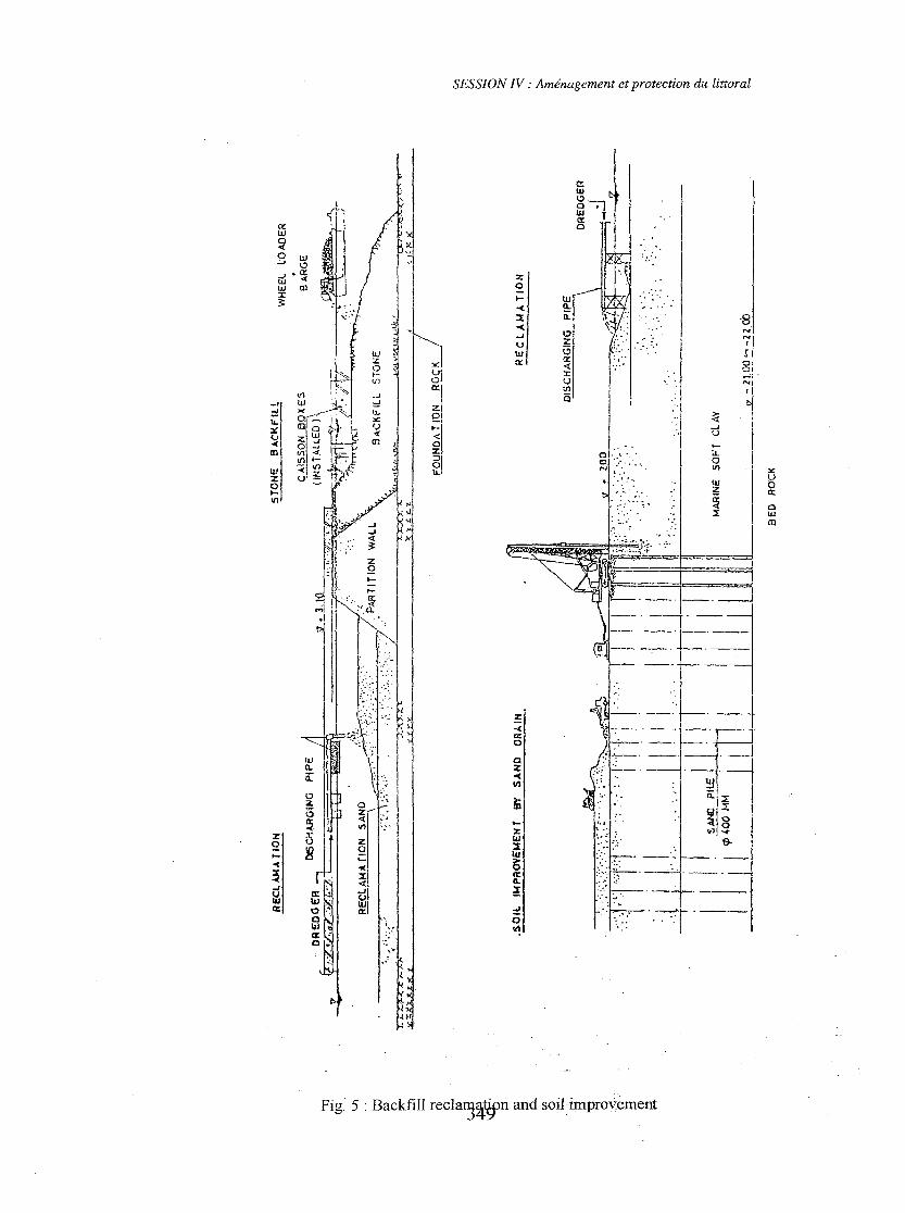
4) Sequence ofreclamation (Figure 5)
Materials so transported was dumped directly up to -3.5 meter C.D.L, because ofthe draft of hopper barges. Dumping of recIamation materials were spreadedevenly as much as possible in the reclamation area.
As a first step of recIamation, dumping was carried out from north end ofrecIamation area (at small ship quay side) towards the south revetment direction.
Upon finishing the first step of recIamation (up to -3.5 m ; direct dumping byhopper barge), the final step was carried out so as to suck up to the material bycutter suction dredger positioned in the reclamation area.
Borrowed material was dumped just in front of suction dredger in order to dredgeeasily.
344
SESSION IV : Aménagement et protection du littoral
Operation at the mouth of discharge pipe (on land) was controlled by bulldozerand backhoe for prevention of overflow of material to the outside of thereclamation area, final levelling was carried out after the completion ofreclamation work.
4.2.3. Reclamation monitoring
Reclamation monitoring was conducted by installing the settlement plates, whichfabricated by steel plates and tube. Each plate was marked and large red flagand/or flashing light provided for securing and the data were taken at site once aweek.
IncJinometers were installed at the location and depths directed by the engineerand were of the type approved by the engineer.
Detail of monitoring work was consulted with the engineer and submitted to theEngineer for approval prior 10 the beginning of the reclamation work.
Abbreviations and Symbols
GT
ps
PELITAfO-roLWSTeu's
= Gross Tonnage= Power Source (± 1.1 Horse Power)= Pembangunan Lima Tahun (Five Year Development)= Roll on roll off
= Low Water Spring= Twenty Equivalent Unit
Fig. 1 : Ujung Pandang project site
Ni1
T_ "."_*"'I.C:S
. _.... ..• ...•-~~ ..
345
SESSION IV : Aménagement et protection du littoral
a) ll:J:IstIn& : 11lV1
b) 2003 : Pro) •• !
PORT OF MAKASSAR
MlI'ATmtAllU_ COIfT.llNER ZONB
_ .. ""' •.....u..". ....•
IfOLTIPUllPOID ZOIn!
- CO!llmlCW. ZONIl
.11'""'..AR7
LW> AJŒA 1
_ PASSllNGI:I! 1
Fig. 2 MASTER PLAN OF PORT OF ~SAR PERIODE 1997 - 2003
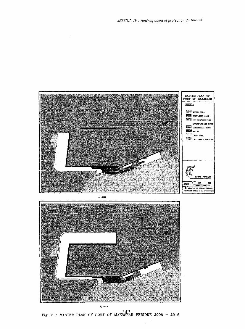
Fig. 3
SESSION N : Aménagement et protection du littoral
i!lI!!II Y&TIlR A1tE&
_ œmAllCŒml'Ol
1lI!lIll •••• .."...,....,.,,,,,,,,,
\) 2018
MASTER PLAN OF PORT OF MAKi~1R PERIODE 2008 - 2016
SESSlON IV : Aménagement et protection du littoral
.-10.1.-
~Vi
C)
ii~
W
l1.
•..«::1 z;:) c c!l.....
r,'.. \
'.
,.\
~IIl
1t1
:1~I~
1
1
11
01.,
r
1
,;Z;'
.• 1~I••• lX t~ al.-
<UJ'"'-<
~g1ftCI
>-% -1.0( 0-." eL~111
J1
4
zo...-<...lXo~VIZ0«
lX•..
al
II ~l
J"I' 01
, ëH-{I
/ 'i ~,
r ,1 ~!
lf, 1
1
Fig. 4 : DredgingJ!J.S sand replacement
SESSION IV: Aménagement et protection du littoral
x:Uoa:
clUm
-8N"';')
ri81.-','NI,
.. ".0. :- ..." .. : .
:zo...-«2-<..JUIIIŒ
d~l-.::-
'~ ~I
r~ \1
Qz-<
~ ~.
,,\
ln
~l r~1~
>-z
i"
z
~~
lU2 :::t...lU
-<~
~a::
ilc-
Sa: :' ~
l.lJ .,CI: ~ ". :=
~0
litcr ~,',
c"""
-.
'"1
~» gjr . III
j .~
.J :\_1
tlJ1
=:!::t
"~~
lt..01lI.
t~L'"
~lxu
<.J
<{
-«co
10
!Il <1. -
!Il 1- L .• êl- III >tll 0' ~ t <z 0 ~I
•.. III
:z:
r"12
>-
Fig: 5 : Backfill recla~~~n and soiHmproyement