drilling day 3 - wildwell.com · air allows under balanced circulation resulting in formation fluid...
TRANSCRIPT

W IL D W E L L C O N T R O L
AIR DRILLING

W IL D W E L L C O N T R O L
Air Drilling
You will learn the basics of:
• Air drilling equipment
• Types of air drilling
• Differences between mud and air drilling
You will learn how to apply well control
principles to air drilling operations.
Learning Objectives
W IL D W E L L C O N T R O L
Air Drilling Technology
Air is used instead of drilling fluids
Air is used in hard rock formations.
Air compressors used instead of mud
pumps.
Boosters pump for air pressure.
BOP equipment is completely
different.
Drilling with a gas in the blooey line
all the time.
What is Air Drilling?

W IL D W E L L C O N T R O L
Air Drilling Site

W IL D W E L L C O N T R O L
Why Use Air Drilling?
No Pay Zone Damage
Increased Penetration Rate
Deviation Control
Differential Sticking Reduction
Lost Circulation Control
Lower Bit Costs
Continuous Pay Zone Evaluation
Tolerates Formation Fluid Influx
Low annular Friction
Low Air Volume Requirements
Advantages

W IL D W E L L C O N T R O L
Pay Zone Drilling
Many gas reservoirs or pay zones experience very low bottom hole formation pressures and
gradients, and are marginal producers when drilled based with a fluid based drilling system.
The economics of producing these wells becomes greatly hampered when drilled with
conventional drilling fluids.
The (pay zone) systems supplied by different service companies can be readily adaptable.
W IL D W E L L C O N T R O L
Pay Zone Hazards
The use of air to drill through these pay zones prevents skin damage and overbalancing which
are both common with mud. The major advantage is that the sensitive pay zone is not exposed
to any fluids. In addition, an inexpensive flow test can be easily conducted without pulling the drill
string out of the hole.

W IL D W E L L C O N T R O L
Applications for Air Drilling Use
Low pressure reservoirs
Dry, hard formations
Wet, hard formations
Unconsolidated formations
Fractured formations
Deviated formations
Large diameter holes

W IL D W E L L C O N T R O L
Air Drilling Unit

W IL D W E L L C O N T R O L
Advantages of Air for Drilling
Used where drilling muds would damage formations.
For economics. High penetration rates.
Air is used in hard rock formations where there is no, or depleted pressure.

W IL D W E L L C O N T R O L
Advantages of Air Circulation
Air allows under balanced circulation resulting in formation fluid entry to the well bore and
eliminating drilling fluid and cutting damage to the formation.

W IL D W E L L C O N T R O L
Air Drilling Limitations
Air drilling is not used:
If conventional muds must be used
Areas with frequent water zones
High pressure zones
Unstable formations
• Most of the time when a rig drills this type of zone the well is lost!
• Most wells in the Northeast are low/pressure-high/volume.
• Some of these wells produce up to 70 million cubic/ft of gas.

W IL D W E L L C O N T R O L
Rental of Surface Equipment
Most air and gas drilling equipment is available on a rental basis from contractors that supply
various air and gas drilling equipment.
The contractors supply the necessary surface equipment to carry out air drilling operation
equipment to rotary drilling contractors.

W IL D W E L L C O N T R O L
Air Compressors

W IL D W E L L C O N T R O L
Compressors and Boosters
Compressors are equipped with after-cooling systems to cool the output flow stream to the
acceptable limits (about 150° to 190°F).
The number of compressors needed depends on the expected characteristics of the borehole as
well as the surface location (i.e., elevation).
The necessary manifold piping to connect the compressors and boosters to the rig equipment is
supplied by the air and gas drilling equipment contractor.
The compressors supply initial air under pressure (100 psi to 300 psi) for drilling or for charging
the booster.
If additional pressure for drilling is needed, the booster can utilize the compressor’s output and
increase the line pressure to as much as 1,500 psi.

W IL D W E L L C O N T R O L
Compressors and Boosters
• The pump injects water, chemical corrosion inhibitors, and liquid foamers into the high pressure air/gas line after initial compression and boost compression of the air/gas.
• Even in dry air (or dust) drilling, some water and chemical corrosion
inhibitors may be injected.
• In mist drilling, a corrosion inhibitor should be injected with the water.
• In normal unstable foam drilling, a liquid foamer, which usually has a corrosion inhibitor, is injected.
Chemical or Water Tank and Pump

W IL D W E L L C O N T R O L
Compressors and Boosters
Solids Injector
• This is used to inject hole-drying powder into the wellbore to dry any water seeping into the borehole
from water-bearing formation; it is also used to inject other solids, such as those that reduce torque
between the drill string and the borehole.
Meter for Measuring Air (or Gas) Volumes
• A standard orifice plate meter is generally used for measuring air (or gas) injection volumes.

W IL D W E L L C O N T R O L
Air Compressors (Boosters)

W IL D W E L L C O N T R O L
Standard Air Equipment
900 CFM-350 psi discharge two stage compressor.
Two stage booster.
Variable speed/displacement mist pump (35 gpm@ 1,850 psi).
Variable speed/displacement chemical Injection pump (10 gpm@ 1,850 psi)
1,000 gallon water storage tank with charger pump.

W IL D W E L L C O N T R O L
Trailer Mounted Equipment Example
• One Sulliar 900 CFM-350 psi discharge
Rotary Screw Two Stage Compressors
powered by Detroit Diesel 475 HP 12V.
• One Joy WB 12 15,000# Rod Load
Reciprocating Two Stage Booster
Powered by Detroit Diesel 320 HP
8V71.
• Hydraulic powered Variable
Speed/Displacement Positive
Reciporcating Tri-Plex Mist Pump
capable of 35 gallons per minute @
1,850 psi.
Trailer Mounted Unit Components:

W IL D W E L L C O N T R O L
Trailer Mounted Equipment Example (cont.)
• Hydraulic powered Variable Speed/Displacement Positive Reciporcating Tri-Plex Chemical Injection
pump capable of 10 gallons per minute @ 1,850 psi.
• 1,000 Gallon Water Storage Tank with Hydraulic Powered Charge Pump.

W IL D W E L L C O N T R O L
Air/Gas Equipment Suppliers
The air/gas equipment supplier usually
provides the following:
• All necessary manifold piping to connect the compressors and booster to the rig equipment.
• The air scrubber.
• The chemical tank and pump.
• The solids injector equipment.
• Air and gas metering is provided as part of the pipe manifold.

W IL D W E L L C O N T R O L
Drilling Contractor Supplies
The drilling contractor supplies the majority of the drilling equipment. Additionally, contractors
typically also provide the following for air operations:
• Compressors
• Booster
• Float valve subs
• Kelly
• Rotating head
• Bleed-off line
• The sample catcher
• The bleed-off line
• Air (or gas) jets
• The pilot light
• The gas sniffer
• The burn pit
• Blooey line

W IL D W E L L C O N T R O L
Float Valve Subs
• Run at the bottom and near the
top of the drill string.
• The bottom float valve sub
prevents the backflow of cutting
into the drill string during
connections or other air (or gas)
flow shutdowns that would
otherwise plug the bit.
• The bottom float valve sub will
also aid in preventing extensive
damage to the drill string in the
event of a downhole fire.
Float Valve Subs

W IL D W E L L C O N T R O L
Float Valve Subs
The top float valve sub (optional) will aid in retaining high-pressure air within the drill
string while making connections.
The upper float valve should be released by opening it when it comes out of the hole.
This can be done with a sinker bar or a wire line.
• Pressure may be trapped and caution used when opening the valve.
Some operators use ported valves to allow bleeding of pressure during trips.

W IL D W E L L C O N T R O L
Scrubber
This removes excess water from the injected air (or gas) stream to ensure that minimal moisture
is circulated (where dry air is required) and to protect the booster.

W IL D W E L L C O N T R O L
Equipment Differences
The BOP stacks are somewhat different than most areas.
Air drill rigs use air heads or rotating heads on the top of the stack. This is the only line of
protection from a blowout - not a kick.

W IL D W E L L C O N T R O L
BOP Requirements
Below is a typical example of BOP requirements:
• The 13-5/8” 3M annular preventer installed on the 13-3/8” casing (Test pressure – 500 psi or maximum
discharge pressure of 2-stage air).
• The 11” 5M double ram BOP & 11” 5M annular preventer (test pressure – 4,000 psi for double ram BOP,
2,000 psi for annular preventer) installed on the 9-5/8” casing. A 5,000 psi kelly valve(s) should be used
and tested with the 11” 5M BOP stack.

W IL D W E L L C O N T R O L
BOP Requirements
Rotating Kelly Packer:
• Also called a rotating head or rotating blowout preventer (RBOP).
- Packs off the annulus return flow from the rig floor (i.e., seals against the rotating kelly) and diverts
the upward flowing air (or gas) and cuttings to the blooey line while allowing pipe rotation and
up/down movement.
• Little pressure (a few psi) exists in the annular flow at the rotating head.
- If reverse circulation is utilized, a pressure of several hundred psi is exerted on the rotating head.
• A hexagonal kelly should be used because the RBOP cannot effectively seal on a square kelly.

W IL D W E L L C O N T R O L
BOP Requirements
All BOP’s must be pressure tested to the listed test pressures before the drilling of new hole
commences. A test plug is employed for use on the 9-5/8” casing. The BOP’s should be function
tested as frequently as required by operator.
• The 13-5/8” 3M BOP’s are installed prior to drilling out of the 13-3/8” casing shoe. The 11” 5M BOP’s
are installed prior to drilling out of the 9-5/8” casing.

W IL D W E L L C O N T R O L
BOP Setup on Air Drilling Rig

W IL D W E L L C O N T R O L
BOP Showing RBOP
W IL D W E L L C O N T R O L
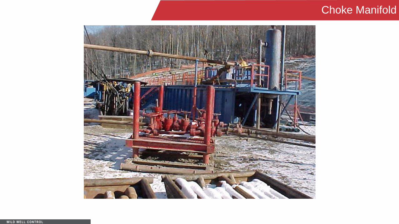
Choke Manifold

W IL D W E L L C O N T R O L
Choke Manifold

W IL D W E L L C O N T R O L
Power House for Top Drive

W IL D W E L L C O N T R O L
Instrumentation
In addition to normal rig instrumentation, accurate pressure gauges should be installed in the low
and high pressure air (or gas) lines.
In particular, a gauge should be installed at the stand pipe and another at the meter run after the
compressor (or booster).
If possible, both pressure gauges should be provided with 12 or 24 hour pressure recorders.
W IL D W E L L C O N T R O L
Instrumentation
The recorder at the meter run is a part of the orifice meter where constant pressure and
differential pressure are measured.
Measurements at both stations will allow easy calculation of air volume output, which is very
important should air pressure decrease or increase during drilling.
Also, a high pressure alarm set to indicate any unusual increase in air/gas injection drilling
pressure should be installed on the rig floor.
These pressure changes are important and helpful in determining problems down hole.

W IL D W E L L C O N T R O L
Bleed - Off Line
The bleed-off line bleeds pressure in the stand pipe, rotary base, and the drill pipe. It allows air or
gas in the string assembly to vent pressure directly to the blooey line.
The bleed-off line is generally used when making connections and allows rig operators to quickly
reduce pressure in the flow lines prior to connections or making trips.

W IL D W E L L C O N T R O L
Blooey Line
This carries exhaust air and cuttings coming from the annulus to the flare pit.
The length of the blooey line should be sufficient to keep dust exhaust from the line from
interfering with the rig area operations.
The length usually used is about 100 ft to 300 ft.
The blooey line should not have any curved joints (i.e. L’s) and should be tied down to the
surface with rigid supports.

W IL D W E L L C O N T R O L
Blooey Line
The end of the blooey line should terminate downwind from the prevailing wind.
It is important that the ID of the blooey line be as large as practical. 7” lines are used in many
areas.
The large ID diameter blooey lines help compensate for the fluid flow energy loss that will occur
as the flow of air (or gas) and cuttings make the 90° turn at the preventer from vertical flow to
horizontal flow under the rig floor.

W IL D W E L L C O N T R O L
Drilling With Gas in the Blooey Line
As was stated earlier, air drilling operations don’t take kicks, they take blowouts on top of the
ground. They usually know where the pay zones are with sufficient time to get the crew ready for
whatever comes next.
The blooey line should be at least 80 feet down wind of the rig.

W IL D W E L L C O N T R O L
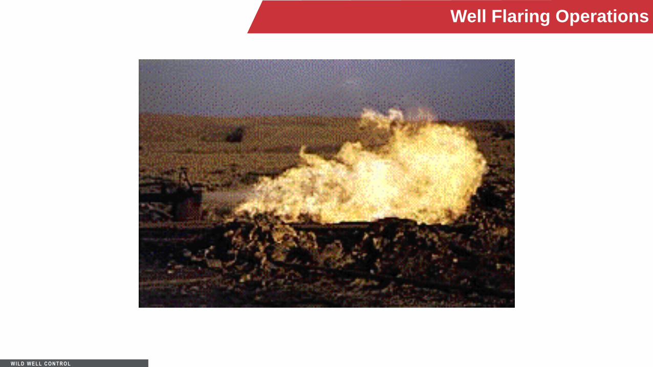
Well Flaring Operations
The choke manifold consists of a 4
1/16” 5M choke line, 2 ea. – 4 1/16”
5M valves, 2 ea. – 2 1/16” 5M valves,
2 ea. 2” 5M manual chokes and the
necessary 4” casing and 2” tubing
lines to the flare pit.
The flow line from the wellhead to the
flare pit is typically constructed of a 7”
line pipe or casing. This flow line
should be buried where possible and
secured with anchors or tubs if it can
not be buried.
An example of a Flare Line Installation would be:
W IL D W E L L C O N T R O L
Well Flaring Operations

W IL D W E L L C O N T R O L
Sample Catchers
A small diameter pipe (≤ 2 in.) is fixed to the bottom of the blooey line.
The small pipe runs into the blooey line at an angle.
The end of the sample catcher is held in the blooey line by a structural support welded to the
small diameter pipe and the blooey line.
W IL D W E L L C O N T R O L
Sample Catchers
A valve is placed on the small pipe outside the blooey line to facilitate sampling.
To sample, the valve is opened and allowed to vent residue material, and a sample of the
cuttings is then taken.
The sample catcher is placed upstream from the de-duster.

W IL D W E L L C O N T R O L
Air (or Gas) Jets
Jets are often used instead of a bleed off line when large amounts of gas enters the annulus.
Switching to the jet allows the reduced air flow from the compressors (and booster) to pass
directly to the blooey line.
The jets pull a vacuum on the blooey line and therefore on the annulus.
• Keeps gas from the rig floor area on connections or trips.

W IL D W E L L C O N T R O L
Pilot Light
A small pilot light or flame should be maintained at the end of the blooey line which will ignite any
gas while drilling.
When drilling with natural gas, the flame should be extinguished until flow is available in the
blooey line.

W IL D W E L L C O N T R O L
Burn Control/Lighting of Flare Line
A propane pilot flame should be located at the end of the flowline and kept burning (depending
upon the situation).
The local fire departments and Emergency Response Centers should be notified when any gas
shows are encountered which cause the flare to light.

W IL D W E L L C O N T R O L
Gas Sniffer
A gas sniffer can be hooked into the blooey line to detect very small amounts of gas entering the
return flow of air and cuttings from the annulus.
The gas sniffer is located on the blooey line just after the return flow from the annulus enters the
blooey line.

W IL D W E L L C O N T R O L
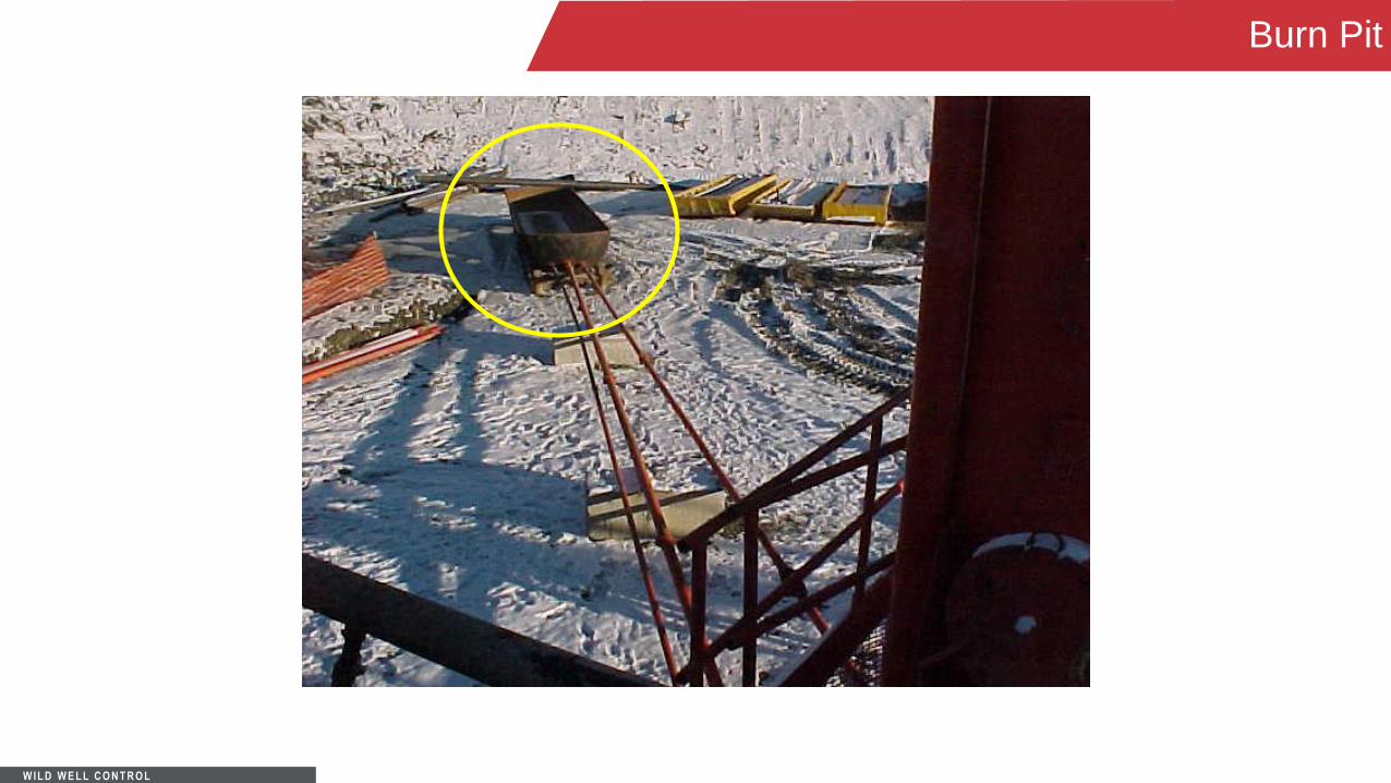
Burn Pit
A burn pit should be provided at the end of the blooey line for an air (or gas) drilling operation.
The burn pit prevents hydrocarbon liquids from flowing to and burning in the reserve pit and thus
prevents a reserve pit fire near the rig.
The burn pit location should be away from the standard mud drilling reserve pit.

W IL D W E L L C O N T R O L
Burn Pit (Half Railroad Tank)
W IL D W E L L C O N T R O L
Burn Pit

W IL D W E L L C O N T R O L
Stabilizing Tools
There are three basic types of stabilizing tools:
- Rotating blade stabilizer
- Non-rotating rubber sleeve stabilizer
- The rolling cutter reamer stabilizer

W IL D W E L L C O N T R O L
Rotating Blade Stabilizer
A rotating blade stabilizer can be a straight blade or spiral blade configuration. In both cases the
blades can be short or long.
Rotating blades are available in two types:
• Shop Repairable
• Rig Repairable

W IL D W E L L C O N T R O L
Rotating Blade Stabilizer
Shop Repairable
• The shop repairable tools are either integral blade, welded blade or shrunk on sleeve construction.
• Welded blade stabilizers are popular in soft formations but are not recommended in hard formations
because of rapid fatigue damage in the weld area.
W IL D W E L L C O N T R O L
Rotating Blade Stabilizer
Rig Repairable
• Rig repairable stabilizers either have a replaceable metal sleeve or replaceable metal wear pads.
• These tools were originally developed for remote locations, but have received widespread acceptance in
the last few years.

W IL D W E L L C O N T R O L
Non - Rotating Sleeve Stablizer
The non-rotating rubber sleeve tool is popular stabilizer because it is a safe tool to run from the
standpoint of sticking and washover.
• Very effective in areas of hard formations such as lime and dolomite.
• Since the sleeve is stationary, it acts like a drill bushing and therefore will not dig into and damage the
wall of the hole.
• The sleeve is made of rubber and temperature over 250°F is not recommended.
• It has no reaming ability and sleeve life may be short in holes with hard or abrasive formations.

W IL D W E L L C O N T R O L
Rolling Cutter Reamer
Rolling cutter reamers are used for reaming and added stabilization in hard formations.
The wall contact area is very small, but it is the only tool that can ream hard rock effectively.
Any time rock bit gauge problems are encountered, the lowest contact tool should definitely be a
rolling cutter reamer.

W IL D W E L L C O N T R O L
Bottomhole Assemblies
In general, the drill pipe and in particular bottomhole assemblies for air and gas drilling are the
same as those used in mud drilling.
Because the rate of penetration in air (or gas) drilling is so rapid, special precautions should be
taken to prevent hole deviations.
Hole deviation problems can be reduced by using less weight on the bit.

W IL D W E L L C O N T R O L
Bottomhole Assemblies
Tri-cone and PDC bits can give high penetration rates, with less weight on the bit.
It is established practice to use hammer and hammer bits using a packed hole assembly to try to
maintain a straight hole.
With air hammer technology advancements of recent years, it is seldom necessary to use
stabilization due to the light bit weights required for maximum penetration.

W IL D W E L L C O N T R O L
• Hole Deviation
This illustration shows
that with normal WOB
angle increases.
By decreasing the WOB
the angle drops back
to vertical.
If the weight is reduced
too quickly, a severe dog
leg may occur.
Bottomhole Assemblies

W IL D W E L L C O N T R O L
Bottomhole Assemblies
Deviation should be controlled throughout drilling operations. This is very important in the upper
part of the borehole. Deviation in this section will create excessive drag and wear on the drill pipe
and tool joints as the depth increases.
This is especially true when drilling harder formations. These high-transient loads can fatigue the
joints and cause premature drill string failure.

W IL D W E L L C O N T R O L
Bottomhole Assemblies
Penetration rates are not highly affected if a stabilization or a pendulum assembly is required
with air hammer and hammer bits.
However, the use of packed-hole or stiff bottomhole assemblies is recommended.
Because of the lack of liquid dampening forces (i.e. water or mud drilling fluid) downhole, the drill
string, particularly the bottomhole assembly and the connections between the bottomhole
assembly and drill pipe, can be subject to vibration stress.
W IL D W E L L C O N T R O L
Drilling Methods
Pay zone drilling
Mist drilling
Stable/stiff foam drilling
Air (dust) drilling
Dusting drilling
Aerated fluid drilling
Gas (in the blooey line)

W IL D W E L L C O N T R O L
Air/Mist Drilling Operation

W IL D W E L L C O N T R O L
Air/Mist Drilling Operation

W IL D W E L L C O N T R O L
Mist Drilling
Mist drilling is used when small amounts of fluid invade the well bore from a wet formation zone.
A small amount of foaming/inhibitor agent is mixed with the water and added to the compressed
air.
Mist drilling maintains high penetration rates while handling the fluid influx.
The quantity of fluid entry that can be handled effectively is dependent on the depth and fluid
content.

W IL D W E L L C O N T R O L
Mist Drilling
A major condition which governs the success of a mist drilling system is the type of formations
exposed. Dry hard,wet hard, fractured, deviated, and low pressure formations are good Mist
drilling prospects. Water sensitive shales or sloughing formations are not good mist drilling
formations.

W IL D W E L L C O N T R O L
Mist Drilling

W IL D W E L L C O N T R O L
Stable/ Stiff Foam
Stable/Stiff Foam Drilling is a mixture of fresh/salt water, surfactant, and appropriate chemical
additives.
• It acts like a drilling fluid, cleaning the hole by suspending and carrying the cuttings out of the wellbore.
• When properly formulated to produce an appropriate liquid volume fraction, stable foam exhibits
superior hole cutting carrying capabilities to that of a drilling fluid.

W IL D W E L L C O N T R O L
Stable/Stiff Foam
The lower air volumes needed for a stable foam system results in reduced equipment
requirements, particularly in large diameter holes.
• Also, the lower annular velocities minimizes hole erosion in unconsolidated formations.
Stable foam is used in wells with relatively low reservoir pressures.
• It is exceptional for drilling more than one horizontal hole in the same wellbore, cased hole sand
cleanouts, milling cased hole packers, and drilling out cased hole plugs.

W IL D W E L L C O N T R O L
Stable/Stiff Foam

W IL D W E L L C O N T R O L
Air (Dust) Drilling
Air (dust) drilling is a circulating method providing a high penetration rate.
Dry air is compressed and boosted to the required circulation pressure to remove cuttings from
the hole with high annular air velocities from 2,500 - 3,000 feet per minute.
Dust drilling is used in medium to hard formation structures, as well as deviated or fractured
zones.

W IL D W E L L C O N T R O L
Dusting

W IL D W E L L C O N T R O L
Dusting

W IL D W E L L C O N T R O L
Dusting

W IL D W E L L C O N T R O L
Aerated Fluid Drilling
Aerated fluid drilling refers to a fluid (water or mud) based drilling system into which air is injected
into the drill string under pressure in order to lower the hydrostatic pressure in the wellbore often
resulting in a desired ECD (Equivalent Circulating Density) of 7 ppg or less.
PH values should be kept very high in order to combat the corrosive environment indigenous to
an aerated fluid system.

W IL D W E L L C O N T R O L
Aerated Fluid Drilling
Aerated fluid systems are very beneficial in severe loss zones where conventional mud systems
cannot function or are cost prohibitive. By regulating air pressure and volumes with the mud
pump rate, a state of equilibrium in the annulus is reached, resulting in neither losses or gains to
the formation.

W IL D W E L L C O N T R O L
Maximum Bottomhole Cleaning
In air and gas drilling, rock cuttings from the free cutting surface are able to leave the surface
rapidly.
The bottomhole cleaning effect of the expanding air/gas at the bit nozzles, can be optimized to
produce the maximum turbulence at the bit/rock cutting surface.
The loose rock stresses of the free cutting surface allow easy rock destruction and initial
movement of the cut particles into the flow stream.
This is counter to the mud drilling situation where rock destruction by the bit is greatly affected by
the fluid hydrostatic pressure at the bottom of the hole.

W IL D W E L L C O N T R O L
Switching to Mud
W IL D W E L L C O N T R O L
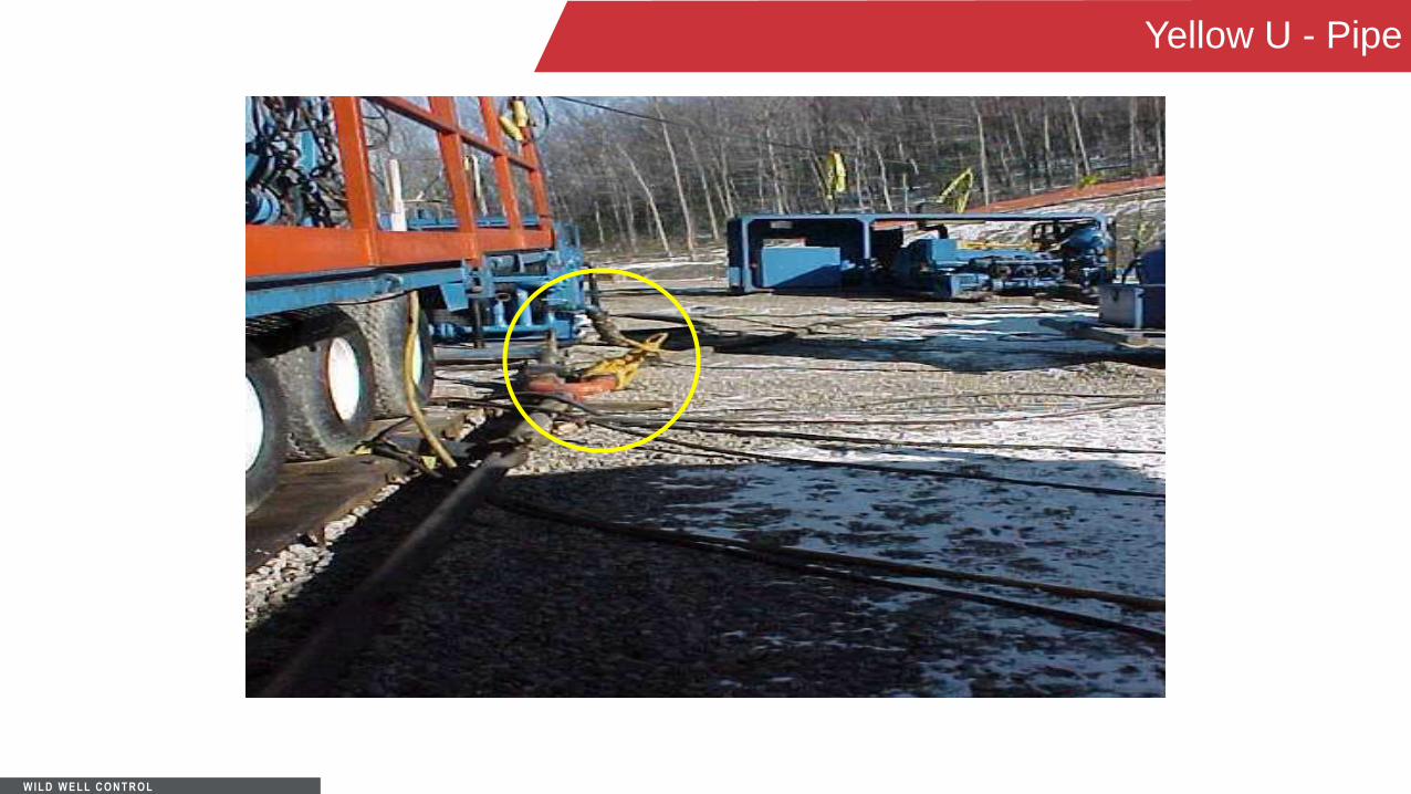
Yellow U - Pipe

W IL D W E L L C O N T R O L
Mud Pits

W IL D W E L L C O N T R O L
Fluid Pumps

W IL D W E L L C O N T R O L
Mud Pits
W IL D W E L L C O N T R O L
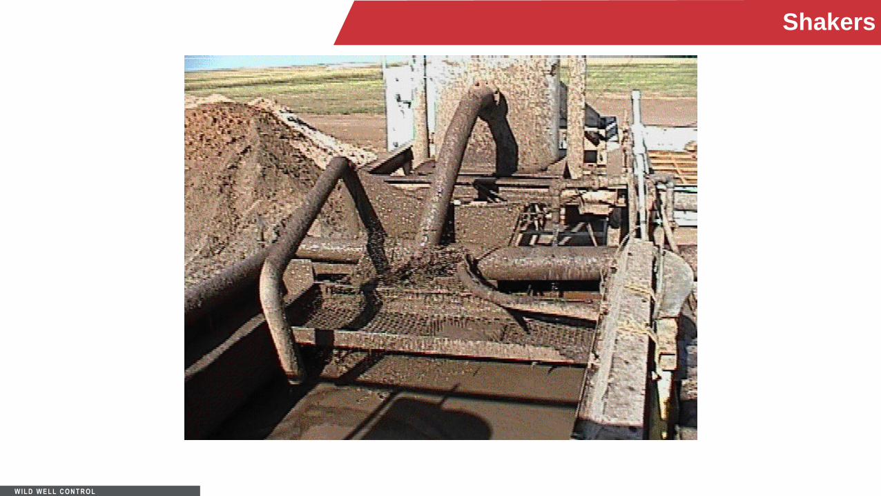
Shakers

W IL D W E L L C O N T R O L
Gas Buster

W IL D W E L L C O N T R O L
Driller’s Panel

W IL D W E L L C O N T R O L
Drill-in Procedure Responsibilities
The Rig Manager and Operator’s Representative should have a safety meeting with each crew
prior to starting their shift to discuss drill-in procedures.
They should designate a safe area in which personnel on location will meet should there be an
accident or uncontrolled well flow necessitating evacuation of the rig floor.

W IL D W E L L C O N T R O L
Drill-in Procedure Responsibilities
The Rig Manager, Operator’s Rep, Mud- logger, or Geologist informs the driller and the rig crew
when the penetration of pay zones is anticipated.
At this time, the Rig Manager positions the rig crew as follows:
• Driller – at control panel and brake handle.
• Derrickman – at accumulator controls.
• Chain hand/Corner hand – positioned to shut down engines if needed

W IL D W E L L C O N T R O L
Drill-in Procedure Responsibilities
All personnel remain in position until instructed otherwise or are relieved.
An Operator’s Representative or the Mud-logger catches cutting samples.
The Operator’s Representative and the Rig Manager remain in close proximity to the driller’s
controls, and maintain checks on all personnel and equipment.
The Rig Manager is responsible for teaching all rig personnel their job tasks during an actual
shut-in.

W IL D W E L L C O N T R O L
Drill-in Procedure Responsibilities
This will include BOP, choke, and accumulator function and engine shutdown procedures.
This training will also include shut-in drills before penetration of any pay zones.
Also, hand signals for all shut-in operations are to be mastered by all personnel on location.

W IL D W E L L C O N T R O L
Before Drill-in
Check HCR Valve – It is to be in the closed position.
Check 4” choke manifold valves – The chokes and manifold valves are checked and are open
to the gas buster and closed to the earth pit.
The chain and corner hands shut down the light plant, then proceed to the safe area.

W IL D W E L L C O N T R O L
Before Drill-in
The Driller and Rig Manager will shut down the rig engines and soap pump engine.
The Driller will then proceed to the safe area and the Rig Manager will proceed to the
accumulator with the Operator’s Representative.
If signaled to evacuate the rig floor, Emergency Shutdown Procedures start immediately.
The Driller chains down the brake handle before evacuating the rig floor.

W IL D W E L L C O N T R O L
During Drill-in
Large gas flows may be encountered at any depth.
There may be a drilling break.
• If a large gas flow is encountered the rotary table will torque-up or possibly lock-up.
The Driller should:
• Back out torque
• Kicks out the rotary clutch
• Picks up the kelly and set the slips high enough on the drill pipe so that the elevators may be latched
below the tool joint
W IL D W E L L C O N T R O L
During Drill-in
If the Operator’s Representative or Rig Manager confirms that the flow needs to be diverted
through the choke manifold; the driller signals the derrickman to open the HCR valve.
After the HCR valve is open, the driller signals the derrickman to close the pipe rams.
If the kelly cannot be pulled from the BOP due to excessive flow or other reasons, and flow must
be diverted through the choke manifold, the driller signals the derrickman to open the HCR valve.

W IL D W E L L C O N T R O L
Pits and Discharge Line

W IL D W E L L C O N T R O L
Location View

W IL D W E L L C O N T R O L
Location View – Pipe Rack

W IL D W E L L C O N T R O L
Choke Manifold Photo

W IL D W E L L C O N T R O L
A Case History
The slides titled “Case History” relate to a
real life scenario.
The slides titled “Training” evaluate the
case history and explore other procedures
to support the case history and/or well
control operations.
Following is a case history -

W IL D W E L L C O N T R O L
Case History Objective
To determine if operations handled a kick successfully while air drilling.
To determine if other procedures/methods would have accomplished the same results as the
method used in the case history.
To tie training objectives into case history.
Draw conclusions to case history from both operational and training views.
W IL D W E L L C O N T R O L
Case History
Location - Pennsylvania
Planned total depth - 9,685 ft
Elevation - 1,105 ft
Geologic prognosis - 17 formations consisting of:
• Grey shale, siltstone, limestone, grey & black shale, sandstone, dolomite, gypsum, salt, and red shale.

W IL D W E L L C O N T R O L
Case History: Casing Program
• 24” Casing
Hole Size: 24 in
Depth: 100 ft
• 20” Casing
Cemented back to surface
Hole Size: 23 in
Depth: 160 ft
• 13 3/8” Casing: 54.5 lb/ft J55
Cemented back to surface
Hole size: 17 1/2” drilled with Smith
H42 hammer bit
Depth: 1,000 ft

W IL D W E L L C O N T R O L
Case History: Drilling Operations
After setting 13 3/8”, began drilling to a target zone of 5,640 ft
• Casing program called for 9 5/8” 40 lb J55 casing to be run upon completion
• Bit 12 3/8” Smith H42 hammer bit
• BHA: NUMA Challenger 125 hammer with 5/8” choke
• 4, 8” OD Drill Collars
• 4 1/2” OD Drill Pipe
• Mud type: Air/Soap

W IL D W E L L C O N T R O L
Case History: Drilling Operations
Anticipated swapping to air/water based gel (3% KCL, 6 lb/bbl Clay-seal) at 4,000 ft
Air requirements: minimum of 4,000 SCFM and 2 Boosters
W IL D W E L L C O N T R O L
Case History Scenario
Company Representative (normally associated with water based drilling) was asked to oversee
the air drilling operation.
At 3,516 ft, rig encountered extremely high increase in flow at blooey line.
• Looked to be mostly gas.
Operations elected to shut in well.

W IL D W E L L C O N T R O L
Training: Shut In Procedures for Air Drilling
What are the procedures for correctly shutting in an air drilling operation?
What are the differences between air and water based shut in procedures?
• Are there any?

W IL D W E L L C O N T R O L
Shut in Procedures for Air Drilling
Raise drill string out of hole until the kelly clears the rotary table.
Shut down compressors and boosters and close kelly safety valve and/or standpipe valve.
Close manifold valve(s) from compressors and boosters to standpipe.
Close annular preventer.
W IL D W E L L C O N T R O L
Shut in Procedures for Air Drilling
Relieve trapped pressures at surface on manifold/drill pipe.
Make sure there is no communication from well on drill pipe side.
Determine stabilization point on casing.
Read and record shut in pressure.
Organize well control operation.

W IL D W E L L C O N T R O L
Case History: Evaluating the Well
Shut in casing pressure on well stabilized at
875 psi.
Drill pipe registered a pressure of 160 psi.
With multiple float valves in the string, why did drill pipe have pressure on it after bleeding down?

W IL D W E L L C O N T R O L
Case History: Define the Problem
Operations determined that there was a small leak between the connections above the last float
valve.
Company Man did not think it would create an operational concern when killing the well.
Would monitor closely during kill operations.

W IL D W E L L C O N T R O L
Case History: Solving The Problem
Company man elects to estimate bottom hole formation pressure using simple calculations.
What formula (s) do you think he used?
Why was he interested in determining formation pressure?

W IL D W E L L C O N T R O L
Case History: Calculations
The Company man performed the following calculations:
Kick Hydrostatic Pressure:
MW ppg x 0.052 x Feet tvd = Hydrostatic Pressure psi
2 ppg gas x 0.052 x 3,516’ = 366 psi
Formation Pressure:
SICP + Hydrostatic Pressure = Formation Pressure psi
SICP 875 psi + 366 psi = 1,241 psi

W IL D W E L L C O N T R O L
Training: Calculations - Question
After determining formation pressure, what calculation did the Company Man use to see if fresh
water would kill the well?
Fresh Water Hydrostatic Pressure:
MW ppg x 0.052 x Feet tvd = Hydrostatic Pressure psi
8.33 ppg x 0.052 x 3,516’ = 1,523 psi
Operations concluded that 1,523 psi of HP would control a formation pressure of approximately
1,241 psi.

W IL D W E L L C O N T R O L
Training: Solving the Well Control Problem
Could the kill weight fluid calculation have been utilized to determine if fresh water would have
killed this well?
Can shut in casing pressure be used to calculate kill weight mud?

W IL D W E L L C O N T R O L
Training: Kill Weight Fluid
Kill Weight Fluid =
SIDPP ÷ 0.052 ÷ TVD to bit + Present Mud
In air drilling, SICP* can be used instead of SIDPP.
875 ÷ 0.052 ÷ 3,516 + 2 = 6.8 ppg Kill Fluid
Note: Assumes a 2 ppg gas.
W IL D W E L L C O N T R O L
Case History: Kill Volume Requirements
Fresh water volumes need to be determined to fill drill pipe and annulus.
What calculations do you think the Company Man used?

W IL D W E L L C O N T R O L
Case History: Tbg., Ann. Vol. Requirements
Company Man elected to simplify calculations at job site.
Drill pipe capacity to MD:
Bbls/ft x Ft = Barrels
0.01422 bbls/ft x 3,516’ = 50 bbls in Drill String

W IL D W E L L C O N T R O L
Case History: DP And Ann. Vol. Requirements
Annular capacity used to TD: Casing ID: 12.615” DP OD: 4.5”
(OD2 – ID2) ÷ 1029.4 = Bbls/ft capacity
(12.6152 – 4.52) ÷ 1029.4 = Bbls/ft
159.14 – 20.25 ÷ 1029.4 = 0.1350 bbls/ft
Bbls/ft x Ft = volume, bbls
0.1350 bbls/ft x 3,516’ = 475 bbls in Annulus
Total Volume = 50 bbls + 475 bbls = 525 bbls
Justification – Company Man elects to use casing capacity to TD to ensure extra water
volume was on location. The concern was this high volume flow could void water from annulus
during well kill operations.

W IL D W E L L C O N T R O L
Training: Calculations
What calculations would you have used to more accurately calculate all tubular and annular
volumes?

W IL D W E L L C O N T R O L
Training: Tubular Volume Requirements
DP capacity = 0.01422 bbls/ft; Length 3,396 ft.
DC capacity = 0.0039 bbls/ft; Length 120 ft.
Bbls/ft x Ft = Barrels
0.01422 bbls/ft x 3,396’ = 48.3 bbls in DP
0.0039 bbls/ft x 120’ = 0.5 bbls in DC
Training Total Barrels in Drill String = 49 bbls.
Company Man’s calculation = 50 bbls.

W IL D W E L L C O N T R O L
Training: Annular Volume Requirements
Ann. Cap. between Csg and DP = 0.1349 bbls/ft
Ann. Cap. between OH and DP = 0.1291 bbls/ft
Ann. Cap. between OH and DC = 0.0866 bbls/ft
0.1349 bbls/ft x 1,000’ = 135 bbls
0.1291 bbls/ft x 2,396’ = 309 bbls
0.0866 bbls/ft x 120’ = 10 bbls
Training Total barrels in Annulus = 454 bbls
Company Man’s calculation = 475 bbls

W IL D W E L L C O N T R O L
Training: Total Volume Requirements
Total Barrels in Drill String = 49 bbls
Total Barrels in Annulus = 454 bbls
Training Total Barrels = 503 bbls
Company Man’s Total Barrels = 525 bbls
On wells where fresh water volumes are critical, these additional calculations may be required.
At this point, operations seems to be on track!

W IL D W E L L C O N T R O L
Training: Additional Volume Requirements
Total Barrels in Drill String = 49 bbls
Barrels Bit to Casing Shoe = 319 bbls
49 + 319 = 368 bbls
What is the importance of knowing this volume? (Please take a few minutes to consider this and
we will address further into the case history scenario.)

W IL D W E L L C O N T R O L
Case History: Determining Strokes and/or Time to Kill Well
Pump output = 0.134 bbls/stk
Company Man then elects to calculate strokes to fill Drill Pipe:
Barrels in DP ÷ Pump Output bbls/stk = Strokes to Pump Vol.
50 bbls ÷ 0.134 bbls/stk = 373 strokes
Bottoms Up Total Volume to be Pumped:
Total Barrels ÷ Pump Output bbls/stk = Strokes to Pump Vol.
475 bbls ÷ 0.134 bbls/stk = 3,545 strokes

W IL D W E L L C O N T R O L
Case History: Kill Procedure Concerns
Operations concerned about the high volume they encountered before shutting in well.
Were concerned that high flow rates could prevent filling annulus with water on location.
Operations elects to kill well through choke rather than through blooey line.
W IL D W E L L C O N T R O L
Case History: Kill Procedure
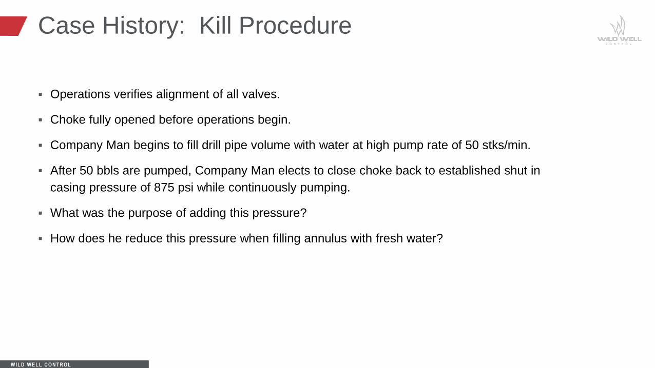
Operations verifies alignment of all valves.
Choke fully opened before operations begin.
Company Man begins to fill drill pipe volume with water at high pump rate of 50 stks/min.
After 50 bbls are pumped, Company Man elects to close choke back to established shut in
casing pressure of 875 psi while continuously pumping.
What was the purpose of adding this pressure?
How does he reduce this pressure when filling annulus with fresh water?

W IL D W E L L C O N T R O L
Case History: Kill Procedure
Company Man elects at this point to monitor time vs. strokes to complete kill operation (bottoms
up) and to reduce casing pressure in relation to gaining hydrostatic pressure with kill fluid (fresh
water).
Bbls ÷ Pump Output bbls/stk = Strokes to pump volume
475 bbls ÷ 0.134 bbls/stk = 3,545 stks to fill annulus
Strokes ÷ Pump Rate stks/min = Time to pump volume
3,545 stks ÷ 50 stks/min = 71 min
What was the reason for swapping to minutes?

W IL D W E L L C O N T R O L
Case History: Kill Procedure
Company Man elects to back off pressure on casing side while utilizing time.
875 psi ÷ 71 min = 12.3 psi/min
Every 8 minutes, Company Man bleeds 100 psi off casing. Was this approximation correct?
Elects to hold remaining 75 psi until shutting down operations.
Does everyone understand why he did this?

W IL D W E L L C O N T R O L
Training: Reduction in Casing Pressure
There are several ways to calculate and monitor casing pressure reduction when gaining fluid
hydrostatic head in the annulus.
The Company Man elected to use time to simplify his operations.
Does anyone know how to use strokes vs. time?

W IL D W E L L C O N T R O L
Pressure Strokes(bit to surface)
875 0
1 787 355
2 699 710
3 611 1,065
4 523 1,420
5 435 1,775
6 347 2,130
7 259 2,485
8 171 2,840
9 83 3,195
10 ? 3,545 (3,550)
Training: Reduction in Casing Pressure

W IL D W E L L C O N T R O L
Training: Reduction in Casing Pressure
Does anyone recommend completing a pressure chart with bit to casing shoe volumes being
considered?
How would this change the beginning of the reduction of 875 psi?
By holding 875 psi until kill fluid reaches casing shoe, have we applied any additional stress to
the formation at the shoe?
We can now answer why the additional calculation (surface to casing shoe volume) is critical in
relation to holding casing pressure.

W IL D W E L L C O N T R O L
Case History Conclusion
From the case history above, do you feel that the Company Man was successful in killing the
well?
Are there any other recommendations or concerns that should have been addressed during this
operation?
Always remember, there are multiple ways to attack a well control operation!!!
W IL D W E L L C O N T R O L
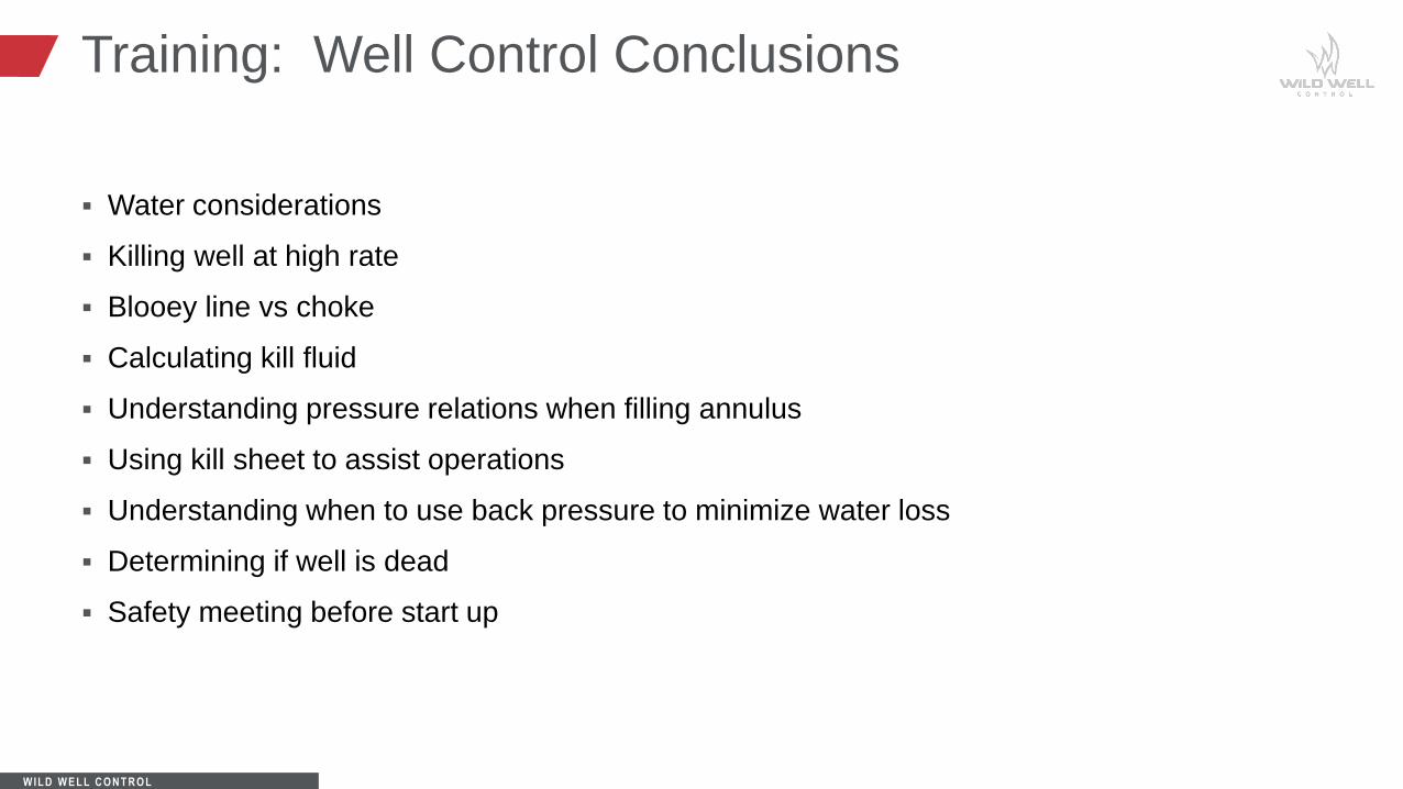
Training: Well Control Conclusions
Water considerations
Killing well at high rate
Blooey line vs choke
Calculating kill fluid
Understanding pressure relations when filling annulus
Using kill sheet to assist operations
Understanding when to use back pressure to minimize water loss
Determining if well is dead
Safety meeting before start up

W IL D W E L L C O N T R O L
Air Drilling
You learned the basics of:
• Air drilling equipment
• Types of air drilling
• Differences between mud and air
drilling
You also learned how to apply well control
principles to air drilling operations.
Learning Objectives