drilling technology and hydraulic fracturing shale gas group b3 (part2)
TRANSCRIPT
7/29/2019 Drilling Technology and Hydraulic Fracturing Shale Gas Group b3 (Part2)
http://slidepdf.com/reader/full/drilling-technology-and-hydraulic-fracturing-shale-gas-group-b3-part2 1/34
1
Report on Drilling
Technology and
Hydraulic Fracturing
in Gas Shales
By Group B3 (Part 2)

7/29/2019 Drilling Technology and Hydraulic Fracturing Shale Gas Group b3 (Part2)
http://slidepdf.com/reader/full/drilling-technology-and-hydraulic-fracturing-shale-gas-group-b3-part2 2/34
2
Group Members
NAME ROLL NUMBER
DHWANI SHAH 10BPE155
ANKIT DIWAKAR 10BPE157
NARENDRA SINGH SHEKHAWAT 10BPE167
PARTH BHUT 10BPE168
ANMOL GARG 10BPE169
HARSH JAJAL 10BPE173
TANMAY SONI 10BPE174
GURVEER SINGH 10BPE175
MADHUKAR KUMAR 10BPE176
SAPNA SAHANI 10BPE177
SHASHWAT SHARMA 10BPE179
HARSHIL SARADVA 10BPE181

7/29/2019 Drilling Technology and Hydraulic Fracturing Shale Gas Group b3 (Part2)
http://slidepdf.com/reader/full/drilling-technology-and-hydraulic-fracturing-shale-gas-group-b3-part2 3/34
3
Acknowledgement
We would like to thank Dr Bijaya Kumar Behera for providing us the opportunity to do this project
and do some background research for the topic. We would also like to thank Prof SSP Singh for
giving us a brief idea about some of the topics covered in this report.
7/29/2019 Drilling Technology and Hydraulic Fracturing Shale Gas Group b3 (Part2)
http://slidepdf.com/reader/full/drilling-technology-and-hydraulic-fracturing-shale-gas-group-b3-part2 4/34
4
Content
SL.NO. TOPIC PAGE NUMBER
INTRODUCTION 5
SUBSURFACE EXPLORATION FOR SHALE GAS 6-10
DRILLING TECHNOLOGY USED 11-16
PROCESS OF FRACTURING 17
ROCK MECHANICS OF FRACTURING 17-22
ROLE OF FRACTURING FLUID 23-25
ROLE OF PROPPANTS 25-28
ENVIRONMENTAL CHALLENGES 29-32
CONCLUSION 33
BIBLIOGRAPHY 34
7/29/2019 Drilling Technology and Hydraulic Fracturing Shale Gas Group b3 (Part2)
http://slidepdf.com/reader/full/drilling-technology-and-hydraulic-fracturing-shale-gas-group-b3-part2 5/34
5
Introduction
Shale gas is natural gas that is produced from a type of sedimentary rock derived from clastic
sources often including mudstones or siltstones, which is known as shale. Clastic sedimentary
rocks are composed of fragments (clasts) of pre-existing rocks that have been eroded,
transported, deposited and lithified (hardened) into new rocks. Shale contains organic
material which was lain down along with the rock fragments. In areas where conventional
resource plays are located, shale can be found in the underlying rock strata and can be the
source of the hydrocarbons that have migrated upwards into the reservoir rock. Shale contains
organic matter (kerogen) which is the source material for all hydrocarbon resources. Over
time, as the rock matures, hydrocarbons are produced from the kerogen. These may then
migrate, as either a liquid or a gas, through existing fissures and fractures in the rock untilthey reach the earth‘s surface or until they become trapped by strata of impermeable rock.
Porous areas beneath these ‗traps‘ collect the hydrocarbons in a conventional reservoir,
frequently of sandstone.
Shale gas resource plays differ from conventional gas plays in that the shale acts as both the
source for the gas, and also the zone (also known as the reservoir) in which the gas is trapped.
The very low permeability of the rock causes the rock to trap the gas and prevent it from
migrating towards the surface. The gas can be held in natural fractures or pore spaces, or can
be adsorbed onto organic material. Aside from permeability, the key properties of shale,
when considering gas potential, are total organic content (―TOC‖) and thermal maturity. TOC
is the total amount of organic material (kerogen) present in the rock, expressed as a
percentage by weight. Generally, higher the TOC, the better is the potential for hydrocarbon
generation. The thermal maturity of the rock is a measure of the degree to which organic
matter contained in the rock has been heated over time, and potentially converted into liquid
and/or gaseous hydrocarbons. Thermal maturity is measured using vitrinite reflectance (Ro).
Because of the special techniques required for extraction, shale gas can be more expensive
than conventional gas to extract. On the other hand, the in-place gas resource can be very
large given the significant lateral extent and thickness of many shale formations. However,
only a small portion of the world‘s shale gas is theoretically producible and even less likely to
be producible in a commercially viable manner. Therefore a key determinant of the success
of a shale play is whether, and how much, gas can be recovered to surface and at what cost.
7/29/2019 Drilling Technology and Hydraulic Fracturing Shale Gas Group b3 (Part2)
http://slidepdf.com/reader/full/drilling-technology-and-hydraulic-fracturing-shale-gas-group-b3-part2 6/34
6
Subsurface Exploration for Shale Gas
Subsurface exploration begins with a license awarded for a defined period of time. But this is only the
first step in the lengthy process that may potentially lead to production. Several years of preliminary
surveys and studies, divided into three successive phases, are needed.
Intended to determine whether a play has commercial potential, subsurface exploration lasts five or
six years. The purpose of this phase is to determine both the size of the deposit and the composition
of the source rock. These factors have a decisive impact on the technical and economic feasibility of
any future production.
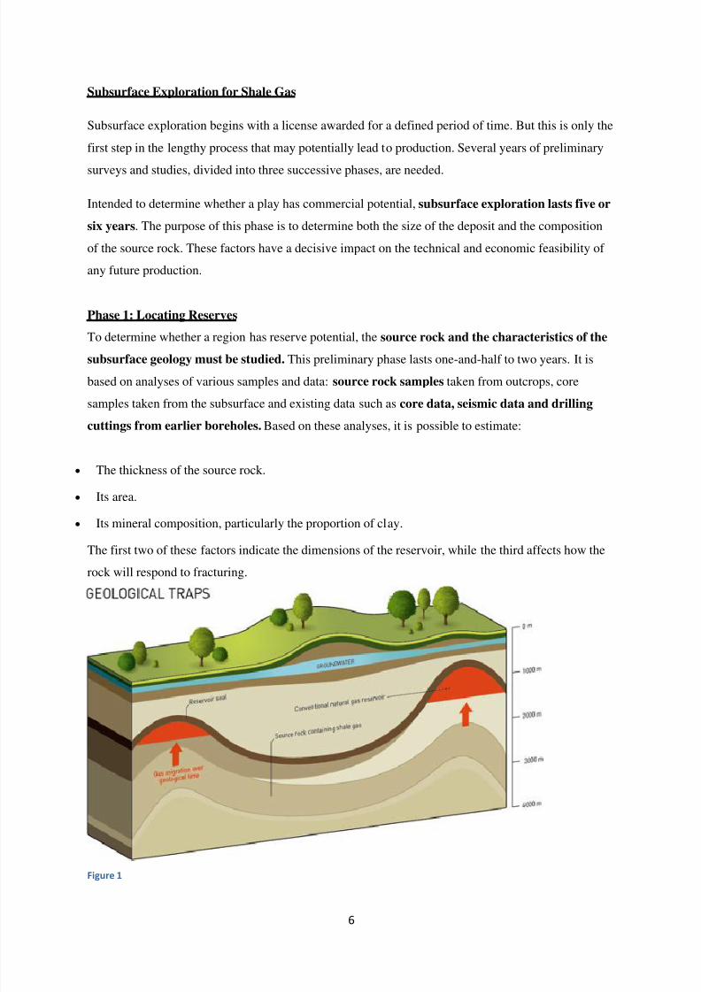
Phase 1: Locating Reserves
To determine whether a region has reserve potential, the source rock and the characteristics of the
subsurface geology must be studied. This preliminary phase lasts one-and-half to two years. It is
based on analyses of various samples and data: source rock samples taken from outcrops, core
samples taken from the subsurface and existing data such as core data, seismic data and drilling
cuttings from earlier boreholes. Based on these analyses, it is possible to estimate:
The thickness of the source rock.
Its area.
Its mineral composition, particularly the proportion of clay.
The first two of these factors indicate the dimensions of the reservoir, while the third affects how the
rock will respond to fracturing.
Figure 1
7/29/2019 Drilling Technology and Hydraulic Fracturing Shale Gas Group b3 (Part2)
http://slidepdf.com/reader/full/drilling-technology-and-hydraulic-fracturing-shale-gas-group-b3-part2 7/34
7
If the dimensions and geological characteristics of the reservoir appear promising, a second phase of
exploration is undertaken to estimate the amount of gas in place in the source rock.
Phase 2: Appraising the Amount of Recoverable Gas
This phase also lasts from half-and-a-half to two years and marks the start of the operational phase of
work. Its purpose is to acquire more detailed data to characterize and the reservoir and apparaise the
gas in place.
Phase 2 focuses on drilling at least one or two conventional vertical wells down to the source rock.
The core samples taken from these boreholes are used to precisely measure rock parameters such
as porosity and permeability. It is essential to know these parameters because:
The less porous the rock and the smaller the pores (the spaces between the grains of the rock), the
less hydrocarbons the rock can hold.
The less permeable the rock (in other words, the less interconnected the pores), the less its fluids can
circulate within.
Other steps include performing fracturing tests on the samples. Phase 2 thus serves to target the most
promising plays in terms of the volume of gas in place and potential extraction. Only the most
promising plays will be graduate to the next phase.
Phase 3: Estimating the Profitability of the Play
This final phase of the process (one to two years) aims to assess the profitability of the play and how
it can be developed, in line with the environmental and CSR assessments previously conducted.
The first step is in situ fracturing tests on at least one or two vertical boreholes in order to study how
the source rock will crack under these conditions. The wells drilled during the previous phase are
usually reused, but it may be useful to drill more to better understand and delineate the area
containing the reserves. Additional seismic surveys may also be conducted.
In situ tests also make it possible to develop the most appropriate techniques, because every drilling
area has its own specific features.
Well production tests take place over several weeks, to study the technical behaviour of the wells and
their profitability.
If the results are encouraging, the following steps take place:
Drilling of horizontal wells to tap s sufficient area of the reservoir.
Hydraulic fracturing of the source rock.
Monitoring of well productivity for a few weeks.
An economic feasibility study incorporating the results of production tests and technical,
environmental and social requirements
7/29/2019 Drilling Technology and Hydraulic Fracturing Shale Gas Group b3 (Part2)
http://slidepdf.com/reader/full/drilling-technology-and-hydraulic-fracturing-shale-gas-group-b3-part2 8/34
8
Only after all these analyses have been performed is a decision made on whether to proceed
with development and operation.
Resource Assessment of Shale Gas Basin
Preliminary geological and reservoir data are assembled for each major shale formation, including the
following key items:
Depositional environment of shale (marine vs. non-marine)
Depth (to top and base of shale interval)
Structure, including major faults
Gross shale interval
Organically-rich gross and net shale thickness
Total organic content (TOC, by wt.)
Thermal maturity (Ro)
These geologic and reservoir properties are used to provide a first order overview of the geologic
characteristics of the major shale gas formations and to help select the shale gas formations deemed
worthy of more intensive assessment.
Establishing the Areal Extent of Major Shale Gas Formations.
Having identified the major shale gas formations, the next step is to undertake more intensive study to
define the areal extent for each of these formations. For this, the study team searches the technical
literature for regional as well as detailed, local cross-sections identifying the shale gas formations of
interest. In addition, the study team draws on internal cross-sections previously prepared by Advanced
Resources and, where necessary, assembles well data to construct new cross-sections. The regional
cross-sections are used to define the lateral extent of the shale formation in the basin and/or to identify
the regional depth and gross interval of the shale formation. Defining the Prospective Area for Each
Shale Gas Formation .An important and challenging resource assessment step is to establish the
portions of the basin that, in our view, are deemed to be prospective for development of shale gas. The
criteria used for establishing the prospective area include:
Depositional Environment.
An important criterion is the depositional environment of the shale, particularly whether it is marine
or non-marine. Marine-deposited shales tend to have lower clay content and tend to be high in brittle
minerals such as quartz, feldspar and carbonates. Brittle shales respond favorably to hydraulic
7/29/2019 Drilling Technology and Hydraulic Fracturing Shale Gas Group b3 (Part2)
http://slidepdf.com/reader/full/drilling-technology-and-hydraulic-fracturing-shale-gas-group-b3-part2 9/34
9
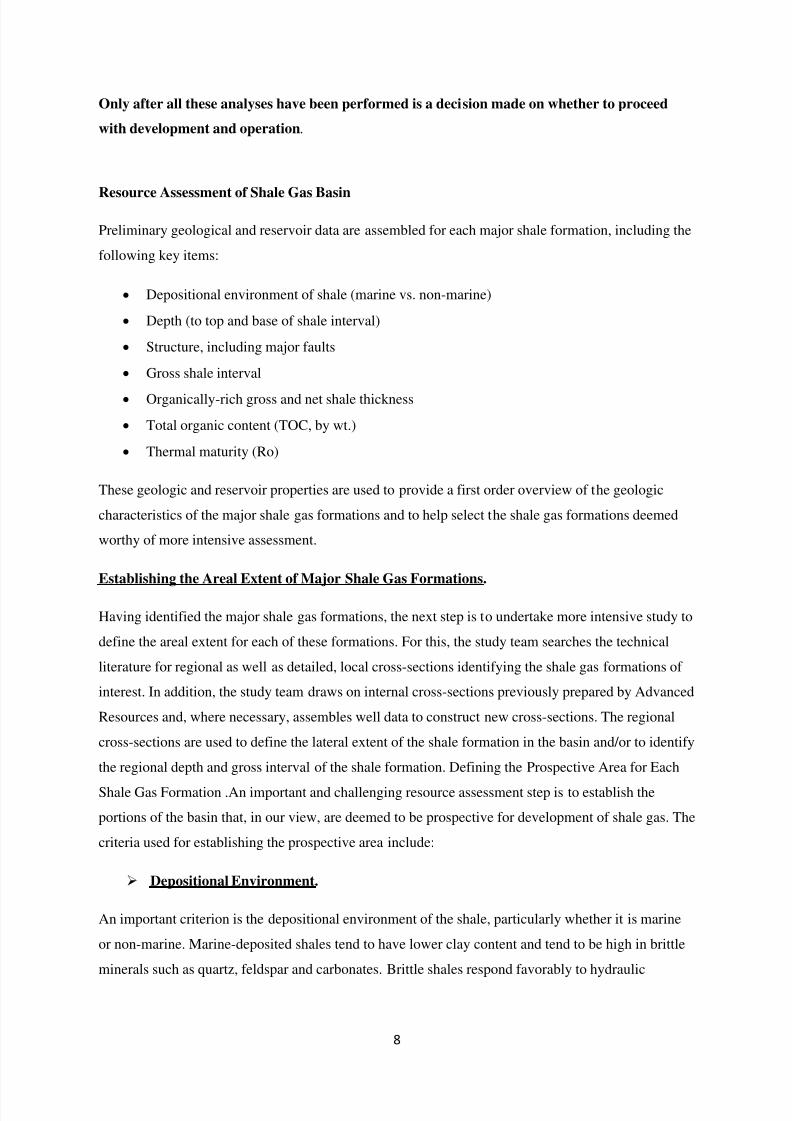
stimulation. Shales deposited in non-marine settings (lacustrine, fluvial) tend to be higher in clay,
more ductile and less responsive to hydraulic stimulation.
Figure 2
Depth
The depth criterion for the prospective area is greater than 1,000 meters, but less than 5,000 meters
(3,300 feet to 16,500 feet). Areas shallower than 1,000 meters have lower pressure and a lower gas
concentration. In addition, shallow shale gas formations have risks of higher water content in their
natural fracture systems. Areas deeper than 5,000 m have risks of reduced permeability and much
higher drilling and development costs.
Total Organic Content (TOC)
Organic materials such as microorganism fossils and plant matter provide the requisite carbon,
oxygen and hydrogen atoms needed to create natural gas and oil. As such TOC is an important
measure of the gas generation potential of a shale formation. In general, the TOC of prospective area
needs to be equal to or greater than 2%.
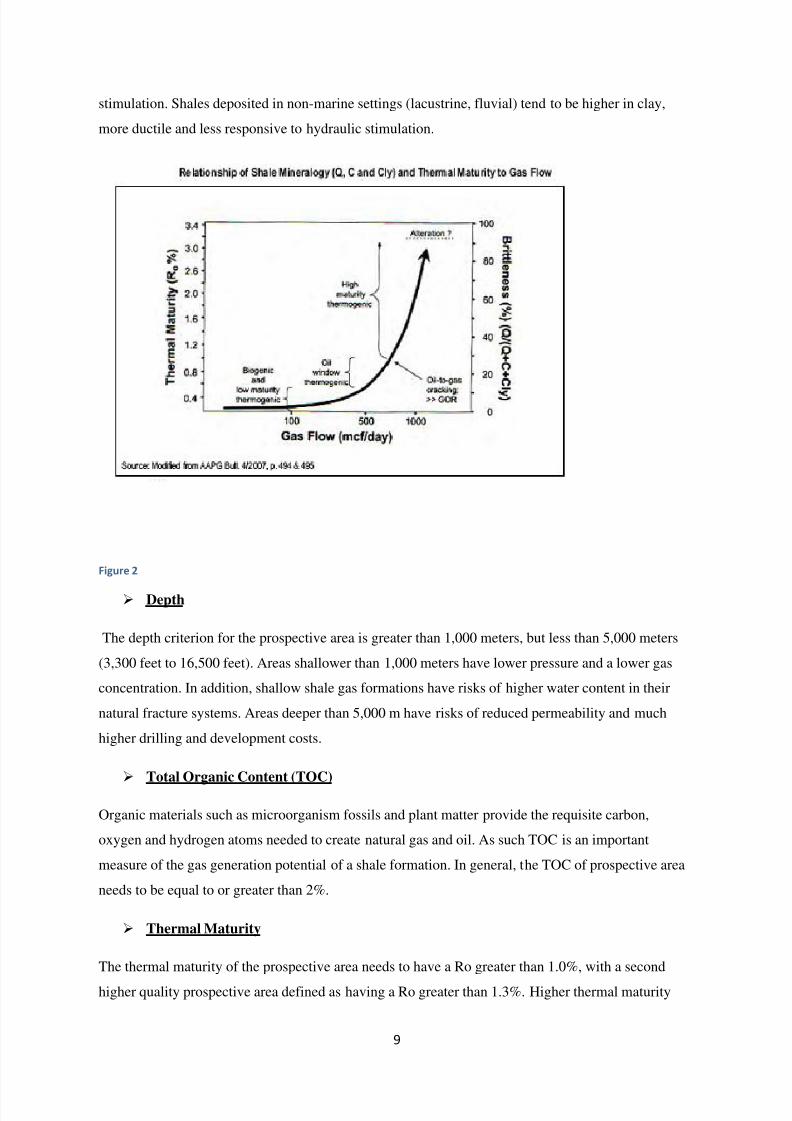
Thermal Maturity
The thermal maturity of the prospective area needs to have a Ro greater than 1.0%, with a second
higher quality prospective area defined as having a Ro greater than 1.3%. Higher thermal maturity
7/29/2019 Drilling Technology and Hydraulic Fracturing Shale Gas Group b3 (Part2)
http://slidepdf.com/reader/full/drilling-technology-and-hydraulic-fracturing-shale-gas-group-b3-part2 10/34
10
settings also lead to the presence of nanopores which contribute to additional porosity in the shale
matrix. Figure 2.7 provides an illustration of the relationship between thermal maturity and the
development of nanopores in the shale matrix.. Thermal maturity measures the degree to which a
formation has been exposed to high heat needed to break down organic matter into hydrocarbons.
The reflectance of certain types of minerals (Ro %) is used as an indication of Thermal Maturity.
Geographic Location.
The prospective area is limited to the onshore portion of the shale gas basin.
Figure 3
7/29/2019 Drilling Technology and Hydraulic Fracturing Shale Gas Group b3 (Part2)
http://slidepdf.com/reader/full/drilling-technology-and-hydraulic-fracturing-shale-gas-group-b3-part2 11/34
11
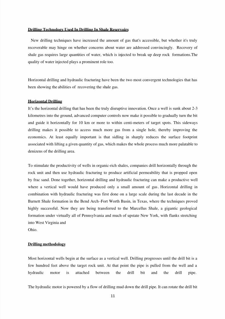
Drilling Technology Used In Drilling In Shale Reservoirs
New drilling techniques have increased the amount of gas that's accessible, but whether it's truly
recoverable may hinge on whether concerns about water are addressed convincingly. Recovery of
shale gas requires large quantities of water, which is injected to break up deep rock formations.Thequality of water injected plays a prominent role too.
Horizontal drilling and hydraulic fracturing have been the two most convergent technologies that has
been showing the abilities of recovering the shale gas.
Horizontal Drilling
It‘s the horizontal drilling that has been the truly disruptive innovation. Once a well is sunk about 2-3
kilometres into the ground, advanced computer controls now make it possible to gradually turn the bit
and guide it horizontally for 10 km or more to within centi-meters of target spots. This sideways
drilling makes it possible to access much more gas from a single hole, thereby improving the
economics. At least equally important is that sidling in sharply reduces the surface footprint
associated with lifting a given quantity of gas, which makes the whole process much more palatable to
denizens of the drilling area.
To stimulate the productivity of wells in organic-rich shales, companies drill horizontally through the
rock unit and then use hydraulic fracturing to produce artificial permeability that is propped open
by frac sand. Done together, horizontal drilling and hydraulic fracturing can make a productive well
where a vertical well would have produced only a small amount of gas . Horizontal drilling in
combination with hydraulic fracturing was first done on a large scale during the last decade in the
Barnett Shale formation in the Bend Arch – Fort Worth Basin, in Texas, where the techniques proved
highly successful. Now they are being transferred to the Marcellus Shale, a gigantic geological
formation under virtually all of Pennsylvania and much of upstate New York, with flanks stretching
into West Virginia andOhio.
Drilling methodology
Most horizontal wells begin at the surface as a vertical well. Drilling progresses until the drill bit is a
few hundred feet above the target rock unit. At that point the pipe is pulled from the well and a
hydraulic motor is attached between the drill bit and the drill pipe.
The hydraulic motor is powered by a flow of drilling mud down the drill pipe. It can rotate the drill bit
7/29/2019 Drilling Technology and Hydraulic Fracturing Shale Gas Group b3 (Part2)
http://slidepdf.com/reader/full/drilling-technology-and-hydraulic-fracturing-shale-gas-group-b3-part2 12/34
12
without rotating the entire length of drill pipe between the bit and the surface. This allows the bit to
drill a path that deviates from the orientation of the drill pipe.
After the motor is installed the bit and pipe are lowered back down the well and the bit drills a path
that steers the well bore from vertical to horizontal over a distance of a few hundred feet. Once the
well has been steered to the proper angle, straight-ahead drilling resumes and the well follows the
target rock unit. Keeping the well in a thin rock unit requires careful navigation. Downhole
instruments are used determine the azimuth and orientation of the drilling. This information is used to
steer the drill bit.
Horizontal drilling is expensive. When combined with hydraulic fracturing a well can cost up to three
times as much per foot as drilling a vertical well. The extra cost is usually recovered by increased
production from the well. These methods can multiply the yield of natural gas or oil from a well.
Many profitable wells would be failures without these methods.
7/29/2019 Drilling Technology and Hydraulic Fracturing Shale Gas Group b3 (Part2)
http://slidepdf.com/reader/full/drilling-technology-and-hydraulic-fracturing-shale-gas-group-b3-part2 13/34
13
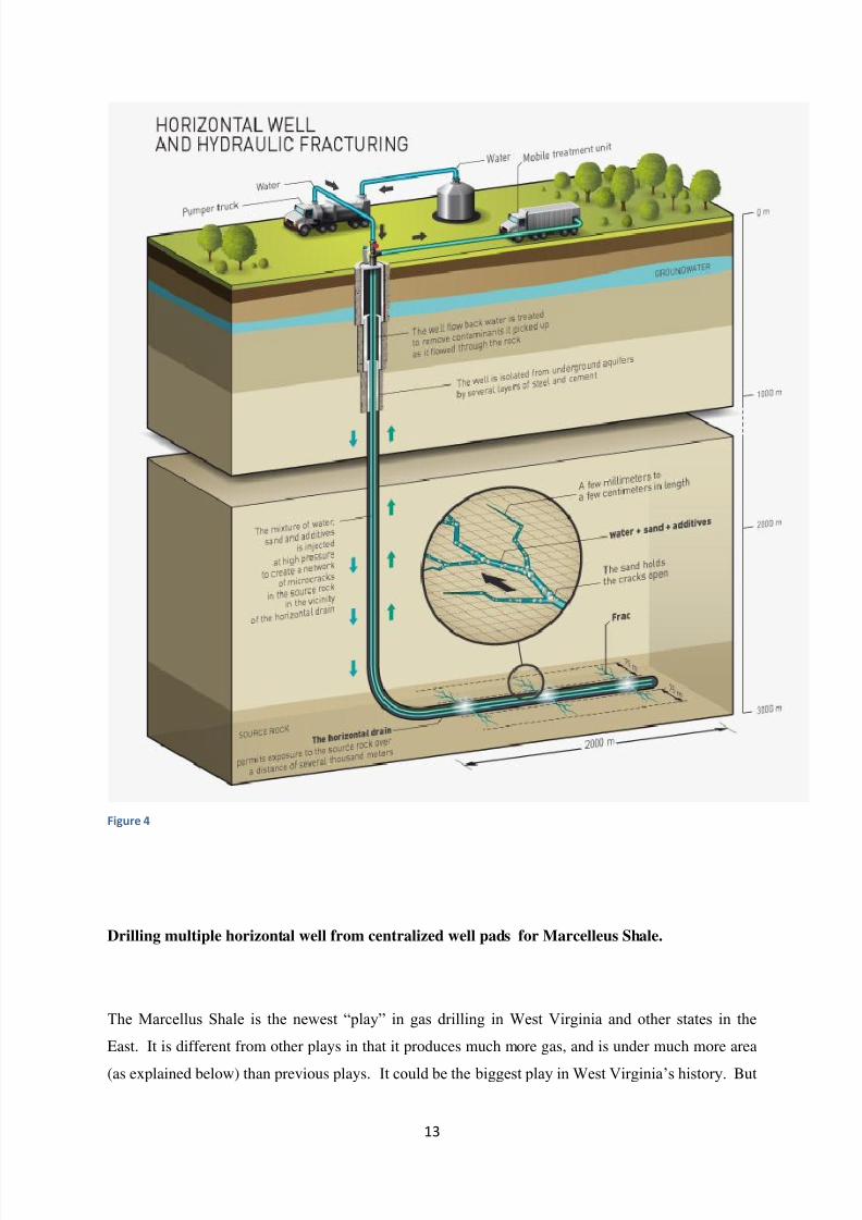
Figure 4
Drilling multiple horizontal well from centralized well pads for Marcelleus Shale.
The Marcellus Shale is the newest ―play‖ in gas drilling in West Virginia and other states in the
East. It is different from other plays in that it produces much more gas, and is under much more area
(as explained below) than previous plays. It could be the biggest play in West Virginia‘s history. But
7/29/2019 Drilling Technology and Hydraulic Fracturing Shale Gas Group b3 (Part2)
http://slidepdf.com/reader/full/drilling-technology-and-hydraulic-fracturing-shale-gas-group-b3-part2 14/34
14
it has much more adverse effect on surface land owners and others in West Virginia for two
reasons. First, shale wells are drilled much closer together, and are therefore more densely numerous
on the surface, than traditional plays in ―sands‖. Second, the new drilling and fracturing techniques
that have for the first time made it possible to economically produce gas from the Marcellus Shale
take up much more land and use much more water for ―fracturing‖ the gas bearing formation. Instead
of a well site with a typical drilling rig and a single drilling pit on 1.5 to 3 acres (plus a couple tractor
trailer loads of water for the ―fracture‖ process), a Marcellus Shale vertical well takes a bigger drilling
rig, a bigger drilling pit, and in addition an impoundment pond the size of an Olympic swimming pool
to hold 600,000 to 1 Million gallons of water for the fracturing process – and many more than 100
tractor trailer loads of water and sand.
Until now, almost all gas wells drilled in the East have been drilled vertically, like the one above. The
driller sets up a drilling rig on a well site directly above the place where he wants to penetrate the gas
bearing formation. He drills straight down until he drills though the gas bearing formation, which in
the case of the Marcellus Shale is up to 100 feet thick in West Virginia. He cements production pipe
into the gas bearing formation. He puts holes out of the production pipe into the gas bearing
formation. He fractures the rock in the area around the 100-foot vertical well bore so the gas will
flow out of the formation faster. And he pipes that gas to the surface and to market. This process is
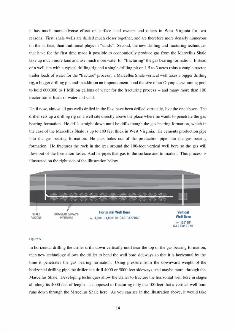
illustrated on the right side of the illustration below.
Figure 5
In horizontal drilling the driller drills down vertically until near the top of the gas bearing formation,
then new technology allows the driller to bend the well bore sideways so that it is horizontal by the
time it penetrates the gas bearing formation. Using pressure from the downward weight of the
horizontal drilling pipe the driller can drill 4000 or 5000 feet sideways, and maybe more, through the
Marcellus Shale. Developing techniques allow the driller to fracture the horizontal well bore in stages
all along its 4000 feet of length – as opposed to fracturing only the 100 feet that a vertical well bore
runs down through the Marcellus Shale here. As you can see in the illustration above, it would take
7/29/2019 Drilling Technology and Hydraulic Fracturing Shale Gas Group b3 (Part2)
http://slidepdf.com/reader/full/drilling-technology-and-hydraulic-fracturing-shale-gas-group-b3-part2 15/34
15
four or more vertical wells to drill, fracture and produce the area of the gas bearing formation that can
be produced by only one horizontal well.
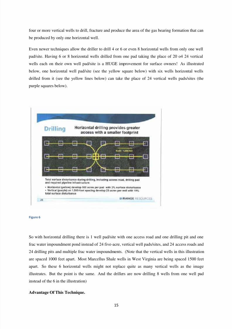
Even newer techniques allow the driller to drill 4 or 6 or even 8 horizontal wells from only one well
pad/site. Having 6 or 8 horizontal wells drilled from one pad taking the place of 20 o4 24 verticalwells each on their own well pad/site is a HUGE improvement for surface owners! As illustrated
below, one horizontal well pad/site (see the yellow square below) with six wells horizontal wells
drilled from it (see the yellow lines below) can take the place of 24 vertical wells pads/sites (the
purple squares below).
Figure 6
So with horizontal drilling there is 1 well pad/site with one access road and one drilling pit and one
frac water impoundment pond instead of 24 five-acre, vertical well pads/sites, and 24 access roads and
24 drilling pits and multiple frac water impoundments. (Note that the vertical wells in this illustration
are spaced 1000 feet apart. Most Marcellus Shale wells in West Virginia are being spaced 1500 feet
apart. So these 6 horizontal wells might not replace quite as many vertical wells as the image
illustrates. But the point is the same. And the drillers are now drilling 8 wells from one well pad
instead of the 6 in the illustration)
Advantage Of This Technique.
7/29/2019 Drilling Technology and Hydraulic Fracturing Shale Gas Group b3 (Part2)
http://slidepdf.com/reader/full/drilling-technology-and-hydraulic-fracturing-shale-gas-group-b3-part2 16/34
16
Not only is horizontal drilling of multiple Marcellus Shale gas wells from centralized well pads/sites
better for surface owners, it is better for lots of other people and interests:
It is less risk to ground water if there are only 6 penetrations in one place from the 6 or 8
wells on the centralized pad instead of 24 all over the place.
It lessens the dangers of other environmental concerns because there is less forest
fragmentation, less inevitable steam siltation from more access roads (and horizontal well
access roads tend to be better constructed and maintained than vertical well access roads) etc.
etc.
It is better for coal owners and coal companies and coal miners. This is because the
horizontal well driller goes through the coal seams while the well bore is still being drilled
vertically. So 6 or 8 well bores are drilled through one spot in the horizontal coal seam, rather
than drilling 24 vertical bores drilled all through the coal seam. Since the well bores are
drilled in one spot, there is less risk to the safety of miners of running into one as they mine
through the coal seam. Because coal companies have to leave a circle of unmined coal
around every gas well bore in order to protect miners, having 24 well bores spread out all
through the coal seam would ―sterilize‖ large quantities of coal from being mined.
Investors in oil and gas drilling probably also are benefitted. Although the initial capital cost
of a horizontal well is greater, they get out more gas faster and cheaper than vertical wells and
so save production costs in the long run.
7/29/2019 Drilling Technology and Hydraulic Fracturing Shale Gas Group b3 (Part2)
http://slidepdf.com/reader/full/drilling-technology-and-hydraulic-fracturing-shale-gas-group-b3-part2 17/34
17
Fracturing
Process
Hydraulic fracturing, commonly referred to as fracking, is the process of creating fissures, or
fractures, in underground formations to allow natural gas to flow. In deep shale gas plays, water, sand
and other additives are pumped under high pressure into the formation to create fractures. The fluid is
more than 99% water and sand, along with a small amount of special-purpose additives. The newly
created fractures are ―propped‖ open by the sand, which allows the natural gas to flow into the
wellbore and be collected at the surface. Normally a hydraulic fracturing operation is only performed
once in the life of a well. Variables such as surrounding rock formations and thickness of the targeted
shale formation are studied by scientists before hydraulic fracturing is conducted. The result is a
highly sophisticated process that optimizes the network of fractures and keeps them safely contained
within the boundaries of the deep shale gas formation.
Process of Hydraulic Fracturing
The following steps are involved in the process of Hydro Fracturing:-
1.) A fracturing treatment operation begins by rigging up a high pressure steel treating or flow
line from special high-pressure fracturing pumps to the well and pressure-testing the
equipment for safety.
2.)
The next step is to inject a large volume of special fluid(s) into a prospective producing
formation at an injection rate that will place sufficient stress on the rock to cause the rock to
physically split (fracture) in one or more places. This initial volume of fluid is termed the
―Pad‖ and typically comprises 20% of total fluid volume.
3.) The Pad fluid is pumped to create enough fracture width to accept proppant particles.
4.) Proppant is typically comprised of size-graded, rounded and nearly spherical white sand, but
may also be man-made particles
7/29/2019 Drilling Technology and Hydraulic Fracturing Shale Gas Group b3 (Part2)
http://slidepdf.com/reader/full/drilling-technology-and-hydraulic-fracturing-shale-gas-group-b3-part2 18/34
18
Rock Mechanics in Hydraulic Fracturing
- A theoretical examination of the mechanisms of hydraulic fracturing of rocks led to
the conclusion that, regardless of whether the fracturing fluid was penetrating, the
fractures produced should be approximately perpendicular to the axis of minimum
principal stress.
- The state of stress, and hence the fracture orientations, is governed by ―incipient
failure‖ (i.e., faulting) of the rock mass.
- In areas subject to active normal faulting, fractures should be approximately vertical.
- In areas subject to active thrust faulting, fractures should be approximately horizontal.
Influence of Pore Pressure
Pore fluids in the reservoir rock play an important role because they support a portion of the
total applied stress. Hence, only a portion of the total stress, namely, the effective stress
component, is carried by the rock matrix. In addition, the mechanical behaviour of the porous
rock modifies the fluid response. Two basic mechanisms highlight this coupled behaviour:
An increase of pore pressure induces rock dilation.
Compression of the rock produces a pore pressure increase if the fluid is prevented from
escaping from the porous network.
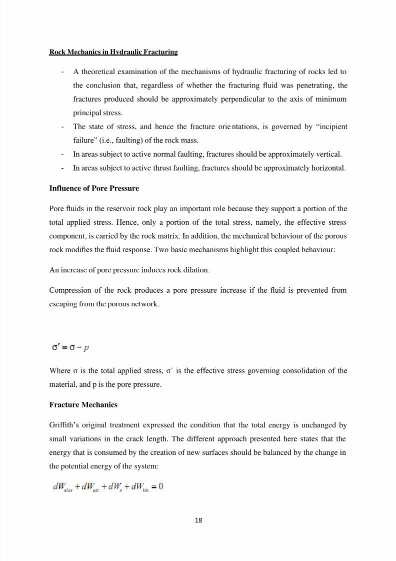
Where σ is the total applied stress, σ´ is the effective stress governing consolidation of the
material, and p is the pore pressure.
Fracture Mechanics
Griffith‘s original treatment expressed the condition that the total energy is unchanged by
small variations in the crack length. The different approach presented here states that the
energy that is consumed by the creation of new surfaces should be balanced by the change in
the potential energy of the system:
7/29/2019 Drilling Technology and Hydraulic Fracturing Shale Gas Group b3 (Part2)
http://slidepdf.com/reader/full/drilling-technology-and-hydraulic-fracturing-shale-gas-group-b3-part2 19/34
19
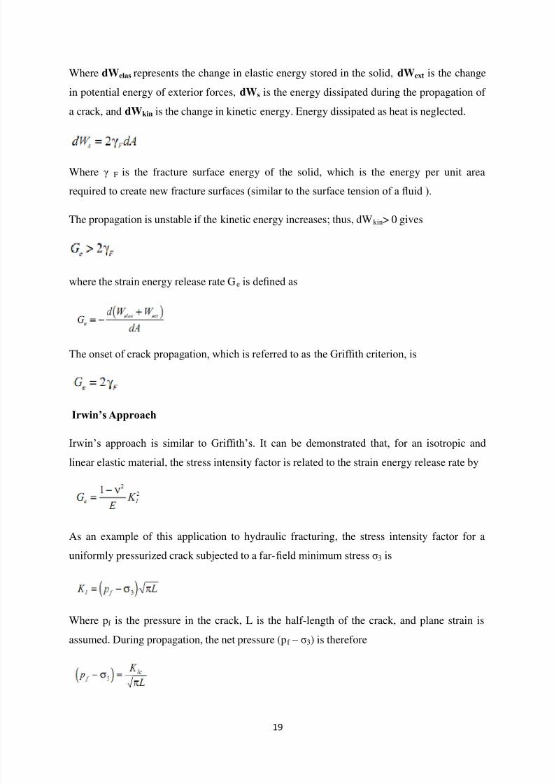
Where dWelas represents the change in elastic energy stored in the solid, dWext is the change
in potential energy of exterior forces, dWs is the energy dissipated during the propagation of
a crack, and dWkin is the change in kinetic energy. Energy dissipated as heat is neglected.
Where γ F is the fracture surface energy of the solid, which is the energy per unit area
required to create new fracture surfaces (similar to the surface tension of a fluid ).
The propagation is unstable if the kinetic energy increases; thus, dWkin> 0 gives
where the strain energy release rate Ge is defined as
The onset of crack propagation, which is referred to as the Griffith criterion, is
Irwin’s Approach
Irwin‘s approach is similar to Griffith‘s. It can be demonstrated that, for an isotropic and
linear elastic material, the stress intensity factor is related to the strain energy release rate by
As an example of this application to hydraulic fracturing, the stress intensity factor for a
uniformly pressurized crack subjected to a far-field minimum stress σ3 is
Where pf is the pressure in the crack, L is the half-length of the crack, and plane strain is
assumed. During propagation, the net pressure (pf – σ3) is therefore
7/29/2019 Drilling Technology and Hydraulic Fracturing Shale Gas Group b3 (Part2)
http://slidepdf.com/reader/full/drilling-technology-and-hydraulic-fracturing-shale-gas-group-b3-part2 20/34
20
Kic is critical stress intensity factor
Stress- Strain Curve
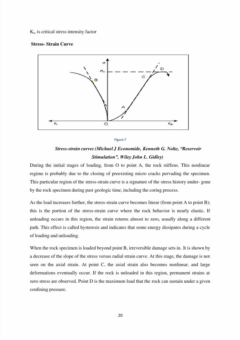
Figure 7
Stress-strain curves (Michael J Economide, Kenneth G. Nolte, “Reservoir
Stimulation”, Wiley John L. Gidley)
During the initial stages of loading, from O to point A, the rock stiffens. This nonlinear
regime is probably due to the closing of preexisting micro cracks pervading the specimen.
This particular region of the stress-strain curve is a signature of the stress history under- gone
by the rock specimen during past geologic time, including the coring process.
As the load increases further, the stress-strain curve becomes linear (from point A to point B);
this is the portion of the stress-strain curve where the rock behavior is nearly elastic. If
unloading occurs in this region, the strain returns almost to zero, usually along a different
path. This effect is called hysteresis and indicates that some energy dissipates during a cycle
of loading and unloading.
When the rock specimen is loaded beyond point B, irreversible damage sets in. It is shown by
a decrease of the slope of the stress versus radial strain curve. At this stage, the damage is not
seen on the axial strain. At point C, the axial strain also becomes nonlinear, and large
deformations eventually occur. If the rock is unloaded in this region, permanent strains at
zero stress are observed. Point D is the maximum load that the rock can sustain under a given
confining pressure.
7/29/2019 Drilling Technology and Hydraulic Fracturing Shale Gas Group b3 (Part2)
http://slidepdf.com/reader/full/drilling-technology-and-hydraulic-fracturing-shale-gas-group-b3-part2 21/34
21
Rock failure (i.e., when the sample loses its integrity) occurs at about this point. Some rocks,
especially those with high porosity, may not exhibit a maximum peak stress but continue to
carry increasing stress (i.e., continue to harden)
Brittle Fracture
Exhibits little or no plastic deformation and low energy absorption before failure.
- Crack propagation spontaneous and rapid. Occurs perpendicular to the direction of the
applied stress, forming an almost flat fracture surface
- Deemed unstable as it will continue to grow without the aid of additional stresses.
Crack propagation across grain boundaries is known as transgranular, while propagationalong grain boundaries is termed intergranular.
Cartoon of simulated brittle fracture
Crack Initiation and Propagation
Cracks usually initiate at some point of stress concentration
-
Common areas include scratches, fillets, threads, and dents
Propagation occurs in two stages: - Stage I: propagates very slowly along crystallographic planes of high shear stress and
may constitute either a large or small fraction of the fatigue life of a specimen
- Stage II: the crack growth rate increases and changes direction, moving perpendicular
to the applied stress.
Figure 8
7/29/2019 Drilling Technology and Hydraulic Fracturing Shale Gas Group b3 (Part2)
http://slidepdf.com/reader/full/drilling-technology-and-hydraulic-fracturing-shale-gas-group-b3-part2 22/34
22
Fracture Mechanics
Uses fracture analysis to determine the critical stress at which a crack will propagate and
eventually fail.
The stress at which fracture occurs in a material is termed fracture strength
- For a brittle elastic solid this strength is estimated to be around E/10, E being the
modulus of elasticity
- This strength is a function of the cohesive forces between the atoms
-
Experimental values lie between 10 and 1000 times below this value
These values are a due to very small flaws occurring throughout the material referred to as
stress raisers.
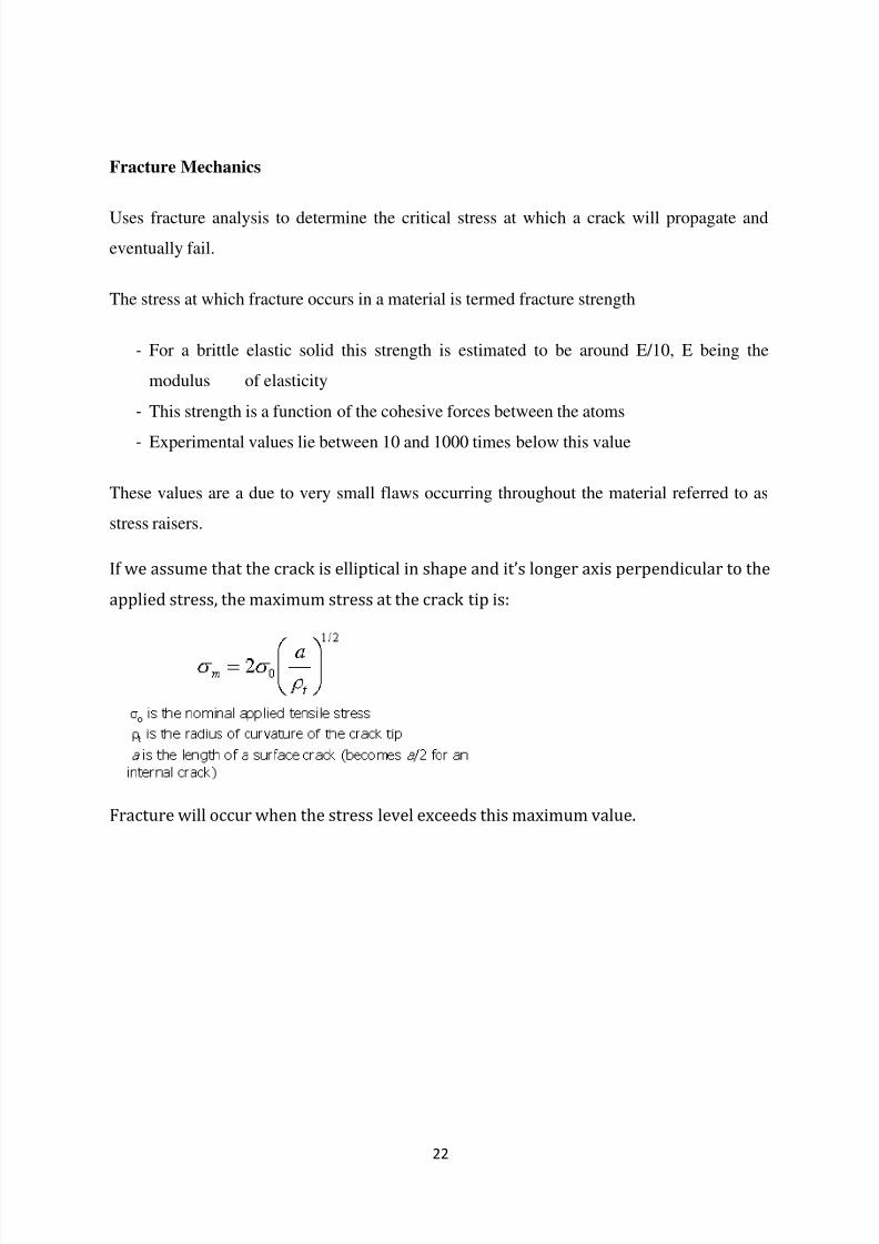
If we assume that the crack is elliptical in shape and it’s longer axis perpendicular to the
applied stress, the maximum stress at the crack tip is:
Fracture will occur when the stress level exceeds this maximum value.
7/29/2019 Drilling Technology and Hydraulic Fracturing Shale Gas Group b3 (Part2)
http://slidepdf.com/reader/full/drilling-technology-and-hydraulic-fracturing-shale-gas-group-b3-part2 23/34
23
Role of fracturing fluid
Composition of the Fracturing Fluid
1.) Base Fluid : Water
To create a network of fractures in the Shale and carry Proppant to the formation.2.) Proppant : Sand
Allows the fractures to remain open so the gas can escape.
3.) Surfactant or gellant : Isopropanol, Trimethyloctadecylammonium, Sodium Xylene
Suphonate
Used to reduce the surface tension of the fracturing fluids to improve liquid recovery
from the well after the frac.
4.) Diluted Acid : Hydrochloric Acid (HCl)
Help to dissolve cement and minerals and initiate fractures
5.) Friction reducer : Polyacrylamide
Reduces friction between the fluid and pipe.
6.) Anti-microbial agents : Glutaraldehyde, ethanol, and methanol
Eliminates bacteria in the water that produces corrosive by-products.
7.) Scale Inhibitor : Ethylene glycol, alcohol , and sodium hydroxide
Prevents scale deposit in the pipe.
8.) Breaker : Sodium Hypochlorite
Breaks down the gelling agent to allow water and sand to flow more easily in and out
the fractures.
9.) Clay control : Quaternary Amine
Prevents clay swelling and clay migration.
10.) Iron control : Trisodium Nitrilotriacetate
Prevents precipitation of metal oxides
11.) De-emulsifier : Isopropanol
Used to break emulsions (water-in-oil or vice-versa)12.) Corrosion Inhibitor : Methanol
Prevents carbonate and sulfate scale precipitation in fracturing systems.
13.) Foam Preventor : Tri-Butyl Phosphate
Reduces viscosity and mud weight.
14.) Crosslinker : Borate salts
Maintains fluid viscosity as the temperature increases
15.) pH adjusting agents : Sodium or potassium carbonate
Maintains the effectiveness of the other components such as crosslinkers.
7/29/2019 Drilling Technology and Hydraulic Fracturing Shale Gas Group b3 (Part2)
http://slidepdf.com/reader/full/drilling-technology-and-hydraulic-fracturing-shale-gas-group-b3-part2 24/34
24
The hydraulic fracturing process has been used commercially as a means of stimulating oil and gas
production for over 40years. In the application of this process, a viscous
Non-Newtonian fluid containing a high proppant concentration is injected down the wellbore at high
rate and pressure to create and extend a fracture system in the formation of interest. Fracturing fluids
are generally in turbulent flow in the wellbore and perforations and in laminar flow in the fracture
system. Characterization of the hydraulic and rheological properties of these fluids in both laminar
and turbulent flow regimes is important for the successful application of this process.
TYPES OF FRACTURING FLUIDS
Since the advent of fracturing fluids in hydraulic fracturing in 1949, fracturing fluid chemistry has
advanced significantly. Today, various types of fracturing fluids are available for reservoirs ranging
from shallow, low temperature formations to those that are deep and hot. Table1lists the most
commonly used fracturing fluid systems in the oil and gas industry.
Water Base
Water base fracturing fluids have been widely used in oil and gas producing wells because of their
low cost, high performance and ease of handling. Many types of water soluble polymers such as guar
gum, hydroxypolypropyl guar (HPG),carboxymethylhydroxypropylguar(CMHPG) andhydroxyethyl
Cellulose (HEC) can be added to water to make it more viscous to improve proppant transport
properties. At higher temperature, various types of cross linkers are used to offset the decrease in
viscosity because of the thermal effect and therefore expand the range of temperature application. The
most popular crosslinkers are metal ions such as borate, Ti(IV), Zr(IV),and AI(III).
Potential problems associated with the water base fluid systems are: formation damage of water
sensitive zones, loss of fracture conductivity due to residue, unbroken gel, and filter cakes. Many
special chemical additives, however, have been developed to make the water base fluid systems
adaptable to formations that maybe adversely affected by water. Breakers are also incorporated to
break the gel fluid at the desired time after treatment so a treated well can be operated again with
minimum delay. Addition of fluid loss additive can enhance the fluid loss control of the water base
fluid systems.Oil Base
Oil base fracturing fluids are primarily for water sensitive formations known to suffer permeability
reduction when exposed to aqueous fluids. Oil base fluids normally employ gelled kerosene, diesel,
distillates and many crude oils. Aluminium salts of organic phosphoric acids are generally used to
raise viscosity, improve temperature stability and proppant carrying capability. Compared to water
base fluids, they are more expensive and more difficult to handle. Oil-base fluids are also more
hazardous because of flammability.
7/29/2019 Drilling Technology and Hydraulic Fracturing Shale Gas Group b3 (Part2)
http://slidepdf.com/reader/full/drilling-technology-and-hydraulic-fracturing-shale-gas-group-b3-part2 25/34
25
Emulsions
Polymer oil-in-water emulsions normally consist of 60 to 70% liquid hydrocarbon as an internal phase
and 30 to 40% gelled water as the external phase. The hydrocarbon may be diesel, kerosene or crude
oil while the aqueous phase maybe gelled fresh water, potassium chloride solution, or some acid
solutions. The emulsions generally provide excellent fluid loss control, less formation damage and
good proppant transport properties. However they are difficult to prepare and somewhat costly.
Alcohol Base
Alcohol base fracturing fluids are specially developed for treating gas producing formations. A gelled
methanol water solution has high solubility in produced gas, excellent viscosity, miscibility with
formation waters, and low surface tension. High vapour pressure and low surface tension permit more
rapid and complete removal of the treating fluid following the treatment even in low permeability,
low pressure formations.
Gas Energized Fluids
Gas energized fluids have steadily increased in usage in fracturing treatments because of their
advantages in reducing proppant and formation damage as well as clean-up cost. Gas energized fluids
usually exhibit very good post-fracture clean up performance when used in low-pressure reservoirs.
Gas energized fluids are generally formed when gas (typically 10to70% carbon dioxide or nitrogen) is
dispersed as small bubbles throughout a continuous liquid phase. The liquid phase typically contains a
surfactant or other stabilizers to reduce phase separation. The liquid phase may be water, water-
methanol mixtures, gelled water, or gelled oils. The inability to measure rheological properties of
these gas energized fluids accurately makes on site quality control and pressure analysis difficult.
Role of Proppants
Proppants are sized particles which are mixed with drilling fluids which keep the fractures open after
the hydraulic treatment. In addition to naturally occurring sand grains,man-made or speciallyengineered proppants,such as resin-coated sand or high strength ceramic materials like sintered
bauxite,may also be used.Proppant materials are carefully sorted for size and sphericity to provide
efficient conduit for production of the fluid from the reservoir to the wellbore.
7/29/2019 Drilling Technology and Hydraulic Fracturing Shale Gas Group b3 (Part2)
http://slidepdf.com/reader/full/drilling-technology-and-hydraulic-fracturing-shale-gas-group-b3-part2 26/34
26
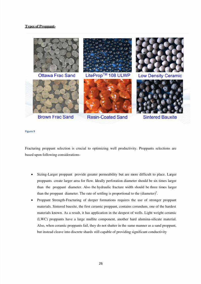
Types of Proppant-
Figure 9
Fracturing proppant selection is crucial to optimizing well productivity. Proppants selections arebased upon following considerations-
Sizing-Larger proppant provide greater permeability but are more difficult to place. Larger
proppants create larger area for flow. Ideally perforation diameter should be six times larger
than the proppant diameter. Also the hydraulic fracture width should be three times larger
than the proppant diameter. The rate of settling is proportional to the (diameter)2.
Proppant Strength-Fracturing of deeper formations requires the use of stronger proppant
materials. Sintered bauxite, the first ceramic proppant, contains corundum, one of the hardest
materials known. As a result, it has application in the deepest of wells. Light weight ceramic
(LWC) proppants have a large mullite component, another hard alumina-silicate material.
Also, when ceramic proppants fail, they do not shatter in the same manner as a sand proppant,
but instead cleave into discrete shards still capable of providing significant conductivity
7/29/2019 Drilling Technology and Hydraulic Fracturing Shale Gas Group b3 (Part2)
http://slidepdf.com/reader/full/drilling-technology-and-hydraulic-fracturing-shale-gas-group-b3-part2 27/34
27
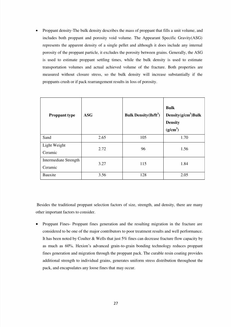
Proppant density-The bulk density describes the mass of proppant that fills a unit volume, and
includes both proppant and porosity void volume. The Appearant Specific Gravity(ASG)
represents the apparent density of a single pellet and although it does include any internal
porosity of the proppant particle, it excludes the porosity between grains. Generally, the ASG
is used to estimate proppant settling times, while the bulk density is used to estimate
transportation volumes and actual achieved volume of the fracture. Both properties are
measured without closure stress, so the bulk density will increase substantially if the
proppants crush or if pack rearrangement results in loss of porosity.
Proppant type ASG Bulk Density(lb/ft3)
Bulk
Density(g/cm3)Bulk
Density
(g/cm3)
Sand 2.65 105 1.70
Light Weight
Ceramic2.72 96 1.56
Intermediate Strength
Ceramic3.27 115 1.84
Bauxite 3.56 128 2.05
Besides the traditional proppant selection factors of size, strength, and density, there are many
other important factors to consider.
Proppant Fines- Proppant fines generation and the resulting migration in the fracture are
considered to be one of the major contributors to poor treatment results and well performance.
It has been noted by Coulter & Wells that just 5% fines can decrease fracture flow capacity by
as much as 60%. Hexion‘s advanced grain-to-grain bonding technology reduces proppant
fines generation and migration through the proppant pack. The curable resin coating provides
additional strength to individual grains, generates uniform stress distribution throughout the
pack, and encapsulates any loose fines that may occur.
7/29/2019 Drilling Technology and Hydraulic Fracturing Shale Gas Group b3 (Part2)
http://slidepdf.com/reader/full/drilling-technology-and-hydraulic-fracturing-shale-gas-group-b3-part2 28/34
28
Proppant pack cyclic stress-During the life of a well, numerous events such as well shut-ins
during workovers, connections to a pipeline or possible shut-ins due to pipeline capacity lead
to cyclic changes in fracture closure stress. Curable resin coated proppants resist these cyclic
stress changes by forming a flexible lattice network that redistributes the stresses through the
proppant pack, reducing individual point loads on each proppant grain. This feature leads to
improved proppant pack integrity and well production.
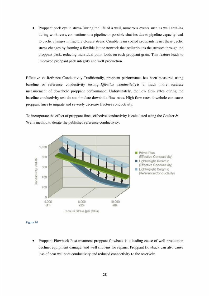
Effective vs Refrence Conductivity-Traditionally, proppant performance has been measured using
baseline or reference conductivity testing. Effective conductivity is a much more accurate
measurement of downhole proppant performance. Unfortunately, the low flow rates during the
baseline conductivity test do not simulate downhole flow rates. High flow rates downhole can cause
proppant fines to migrate and severely decrease fracture conductivity.
To incorporate the effect of proppant fines, effective conductivity is calculated using the Coulter &
Wells method to derate the published reference conductivity.
Figure 10
Proppant Flowback-Post treatment proppant flowback is a leading cause of well production
decline, equipment damage, and well shut-ins for repairs. Proppant flowback can also cause
loss of near wellbore conductivity and reduced connectivity to the reservoir.
7/29/2019 Drilling Technology and Hydraulic Fracturing Shale Gas Group b3 (Part2)
http://slidepdf.com/reader/full/drilling-technology-and-hydraulic-fracturing-shale-gas-group-b3-part2 29/34
29
Hexion‘s curable resin coated proppants eliminate proppant flowback by forming a
consolidated proppant pack in the fracture. This grain-to-grain bonding occurs under a
combination of reservoir temperature and closure stress. This Stress Bond™ (SB) technology
leads to increased proppant pack integrity and well production compared to uncoated and
precured resin coated proppants.
Environmental Challenges
1. Higher fresh water consumption:
A gas discovery occurred in Northern Michigan, revealing potential natural gas reserves in
the Collingwood Shale at depths of ranging from 5,000 to 10,000 feet. Horizontal drilling and
multi-stage fracking will be used to collect this gas, which is different than the hydraulic
fracturing techniques historically used in Michigan. This drilling is not only deeper, it also
uses substantially more fresh water (millions of gallons rather than up to one hundred
thousand gallons) and chemicals. There are many unknowns with respect to the
environmental and long-term impacts.
In Karoo, South Africa, during periods of low stream flow it may affect water supplies for
municipalities and industries such as power generation, as well as recreation and aquatic life.
It may also require water overland piping from distant sources. An average well requires 3 to
8 million US gallons (11,000 to 30,000 m3) of water, typically within one week.
2. Water table contamination in drinking water:
Incidents of surface and ground water contamination from the fracking process have been
reported in other states. In Pennsylvania, state regulators found that gas drilling using high-
volume fracking has caused contaminated drinking water, polluted surface waters, polluted
air, and contaminated soils.
Errors in gas well construction or spills during transportation can occur and lead to water
contamination. Fluids can spill before they are injected and fluids recovered from fracturing
can contaminate surface waters. Additionally, drilling into these formations can create
pathways by which fluids or natural gas itself can find its way into water supplies, if drillers
are not careful. It should be noted also that the horizontal sections of the wells are not cased in
cement and, therefore, leakage from these sections could represent a significant threat to
ground water.
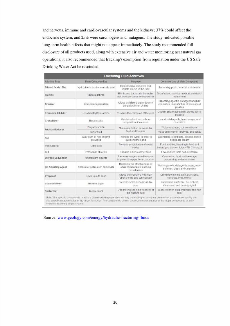
Another 2011 study identified 632 chemicals used in natural gas operations. Only 353 of
these are well-described in the scientific literature; and of these, more than 75% could affectskin, eyes, respiratory and gastrointestinal systems; roughly 40-50% could affect the brain
7/29/2019 Drilling Technology and Hydraulic Fracturing Shale Gas Group b3 (Part2)
http://slidepdf.com/reader/full/drilling-technology-and-hydraulic-fracturing-shale-gas-group-b3-part2 30/34
30
and nervous, immune and cardiovascular systems and the kidneys; 37% could affect the
endocrine system; and 25% were carcinogens and mutagens. The study indicated possible
long-term health effects that might not appear immediately. The study recommended full
disclosure of all products used, along with extensive air and water monitoring near natural gas
operations; it also recommended that fracking's exemption from regulation under the US Safe
Drinking Water Act be rescinded.
Source: www.geology.com/energy/hydraulic-fracturing-fluids
7/29/2019 Drilling Technology and Hydraulic Fracturing Shale Gas Group b3 (Part2)
http://slidepdf.com/reader/full/drilling-technology-and-hydraulic-fracturing-shale-gas-group-b3-part2 31/34
31
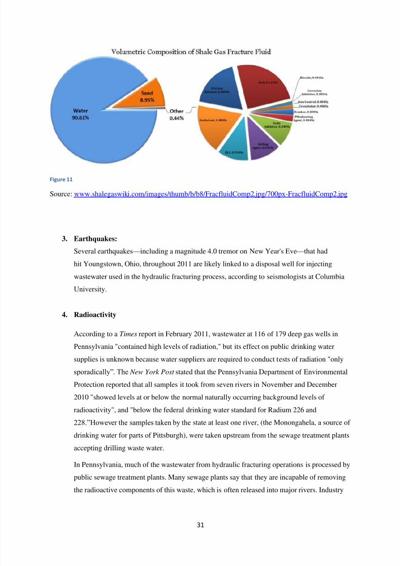
Figure 11
Source: www.shalegaswiki.com/images/thumb/b/b8/FracfluidComp2.jpg/700px-FracfluidComp2.jpg
3. Earthquakes:
Several earthquakes — including a magnitude 4.0 tremor on New Year's Eve — that had
hit Youngstown, Ohio, throughout 2011 are likely linked to a disposal well for injecting
wastewater used in the hydraulic fracturing process, according to seismologists at Columbia
University.
4. Radioactivity
According to a Times report in February 2011, wastewater at 116 of 179 deep gas wells in
Pennsylvania "contained high levels of radiation," but its effect on public drinking water
supplies is unknown because water suppliers are required to conduct tests of radiation "only
sporadically‖. The New York Post stated that the Pennsylvania Department of Environmental
Protection reported that all samples it took from seven rivers in November and December
2010 "showed levels at or below the normal naturally occurring background levels of
radioactivity", and "below the federal drinking water standard for Radium 226 and
228.‖However the samples taken by the state at least one river, (the Monongahela, a source of
drinking water for parts of Pittsburgh), were taken upstream from the sewage treatment plants
accepting drilling waste water.
In Pennsylvania, much of the wastewater from hydraulic fracturing operations is processed by
public sewage treatment plants. Many sewage plants say that they are incapable of removing
the radioactive components of this waste, which is often released into major rivers. Industry
7/29/2019 Drilling Technology and Hydraulic Fracturing Shale Gas Group b3 (Part2)
http://slidepdf.com/reader/full/drilling-technology-and-hydraulic-fracturing-shale-gas-group-b3-part2 32/34
32
officials, though, claim that these levels are diluted enough that public health is not
compromised.
5. Others:
Construction equipment emissions, fracking equipment, and unintentional gas leaks are
sources of negative air emissions during the fracking process. Large areas of cleared land and
many miles of roadways can scar the landscape and result in habitat fragmentation. Drilling
operations also involve lights, 24 hours a day, and noise pollution from the initial month of
drilling the well to the continuous noise generated by operation of compressor stations.
6. Air:
In 2008, measured ambient concentrations near drilling sites in Sublette County,
Wyoming were frequently above the National Ambient Air Quality Standards (NAAQS) of
75ppb and have been recorded as high as 125 ppb. A 2011 study for the city of Fort Worth,
Texas, examining air quality around natural gas sites "did not reveal any significant health
threats." In DISH, Texas, elevated levels
of disulphides, benzene, xylenes and naphthalene have been detected in the air, emitted from
the compressor stations. People living near shale gas drilling sites often "complain of
headaches, diarrhea, nosebleeds, dizziness, blackouts, muscle spasms, and other problems."
In 2012, researchers from the Colorado School of Public Health showed that air pollution
caused by fracking may contribute to "acute and chronic health problems" for those living
near drilling sites.
7/29/2019 Drilling Technology and Hydraulic Fracturing Shale Gas Group b3 (Part2)
http://slidepdf.com/reader/full/drilling-technology-and-hydraulic-fracturing-shale-gas-group-b3-part2 33/34
33
Conclusion
As a source of abundant, high-quality natural gas, the potential of U.S. shale gas has only
begun to be realized. While the challenges to producers may be significant — and
significantly different from play to play — they are not insurmountable, providing the
right technology and experience are on hand.While conventional horizontal directional
drilling technologies have been used to drill shale gas wells, in almost every case, the rock
around the wellbore must be hydraulically fractured before the well can produce significant
amounts of gas, and the cost of fracturing horizontal wells can be as much as 25 percent of the
total cost of the well. To keep development costs under control, there will be a need for
improved exploration, production efficiencies and best practices that combine current
knowledge and new approaches. In most cases, multiwell drilling can afford improved
efficiencies in hydraulic frac stimulation operations, enhancing the percentage of recoverable
gas to boost production rates over the economic threshold, while pad drilling of several
multilateral wells from a single pad will further improve the economies-of-scale and help
reduce location costs while generating a minimal environmental footprint.
7/29/2019 Drilling Technology and Hydraulic Fracturing Shale Gas Group b3 (Part2)
http://slidepdf.com/reader/full/drilling-technology-and-hydraulic-fracturing-shale-gas-group-b3-part2 34/34
Bibliography
1. World Shale Gas Resources:An Initial Assessment of 14 Regions Outside the United States
by US Energy Information Administration
2.
Shale gas extraction in the UK: A review of hydraulic fracturing June 2012 by The RoyalSociety and The Royal Academy of Engineering
3. Recent Advances in the Fluid Mechanics and Rheology of Fracturing Fluids S.N.Shah,
D.L.Lord,and H.C.Tan, Halliburton Services, SPE,1992
4. Dynamic Rock Mechanics Testing for Optimized Fracture Design by Lacy Lewis L, BJ
Services Company, SPE 1997
5. Proppant Selection and Its Effects on the Results of Fracturing Treatments Performed in Shale
Formations, J.M. Terracina, SPE, J.M. Turner, SPE, D.H. Collins, SPE, and S.E. Spillars,
SPE, Hexion,
6. http://www.energyfromshale.org/shale-extraction-process
7. http://www.halliburton.com/public/solutions/contents/shale/related_docs/H063771.pdf
8. http://www.api.org/policy-and-issues/policy-items/exploration/facts_about_shale_gas.aspx