drip canopy - lubingusadrip canopy recommended paper specifications conveyor type paper weight paper...
TRANSCRIPT

Drip CanopyProduct Manual
For all Curve Conveyor Systems
IM-710-00Version: 20130702a


TOC-i
Table of Contents
v20130702a
Section 1 inStallation 1-1Before You Begin 1-1Identify the System Components 1-1
Roll Hanger without Enclosure 1-2Roll Hanger with Enclosure 1-3Support Hanger Assembly 1-4Lock Bar 1-5
Roll Hanger Installation 1-6Roll Hanger without Enclosure Installation 1-6Roll Hanger with Enclosure Installation 1-7
Support Hanger Assembly Installation 1-8Support Bar Installation 1-9Lock Bar Installation 1-10
Installation, Connecting parts 1-11Installation, Bend Unit 1-12Support Hanger Assembly Insallation, Bend Unit 1-13
Section 2 SyStem operation 2-1Recommended Kraft Paper Weight and Width 2-1Installing Kraft Paper Roll, Roll Hanger without Enclosure 2-2Installing Kraft Paper Roll, Roll Hanger with Enclosure 2-3Lock Bar Positions 2-4Pulling Paper Through System 2-5
Section 3 component DetailS 3-1Roll Hanger without Enclosure, T250 - T1000 3-2Support Hanger Assembly, T250 - T1000 3-3Roll Hanger with Enclosure T250 - T1000 3-4
Section 4 General information 4-1Lubing Contact Information 4-1Lubing Regional Sales Contact Information 4-2

TOC-ii
Table of Contents
v20130702a

1-1
Installation
v20130702a
Separate and identify each of the system components. Verify that the system contents match the shipper Packing List.
Note: The Drip Canopy system is comprised of several components that when combined, create a functional system that is specifically engineered for the application. The quantities and part numbers for each supplied component can be verified with the Packing List.
Note: Immediately report any missing items to Lubing Systems Customer Service Department. For a list of current phone numbers and email addresses, please refer to the “General Information” section of this manual.
SeCTIOn 1 InSTallaTIOn
Before You Begin
Identify the System Components
Note: Be sure to observe all Lockout-Tagout procedures prior to performing any work on the system.
Note: Be sure to wear all necessary Personal Protective Equipment prior to beginning any work.
Note: Installation and modifications should adhere to all local, state and national codes and guidelines for electrical and mechanical installation.

1-2
Installation
v20130702a
Roll Hanger without enclosure
Roll Hanger without Enclosure, T250 - T1000
Conveyor Type Part Number Drawing Number Description
250 -- 12S A 140 00A Roll Hanger without Enclosure T250
350 -- 12S A 130 00A Roll Hanger without Enclosure T350
500 -- 12S A 120 00A Roll Hanger without Enclosure T500
750 -- 12S A 110 00A Roll Hanger without Enclosure T750
1000 -- 12S A 100 00A Roll Hanger without Enclosure T1000

1-3
Installation
v20130702a
Roll Hanger with Enclosure T250 - T1000Conveyor Type Part Number Drawing Number Description
250 -- 12S A 340 00B Roll Hanger with Enclosure T250350 -- 12S A 330 00B Roll Hanger with Enclosure T350500 -- 12S A 320 00B Roll Hanger with Enclosure T500750 -- 12S A 310 00B Roll Hanger with Enclosure T750
1000 -- 12S A 300 00B Roll Hanger with Enclosure T1000
Roll Hanger with enclosure

1-4
Installation
v20130702a
Support Hanger assembly
Support Hanger Assembly, T250 - T1000
Conveyor Type Part Number Drawing Number Description
250 -- 12S A 240 00A Support Hanger Assembly T250
350 -- 12S A 230 00A Support Hanger Assembly T350
500 -- 12S A 220 00A Support Hanger Assembly T500
750 -- 12S A 210 00A Support Hanger Assembly T750
1000 -- 12S A 200 00A Support Hanger Assembly T1000

1-5
Installation
v20130702a
lock Bar
Lock Bar, T250 - T1000Conveyor Type Part Number Drawing Number Description
250 -- 12S A 240 03A Lock Bar T250
350 -- 12S A 230 03A Lock Bar T350
500 -- 12S A 220 03A Lock Bar T500
750 -- 12S A 210 03A Lock Bar T750
1000 -- 12S A 200 03A Lock Bar T1000
1-6
Installation
v20130702a
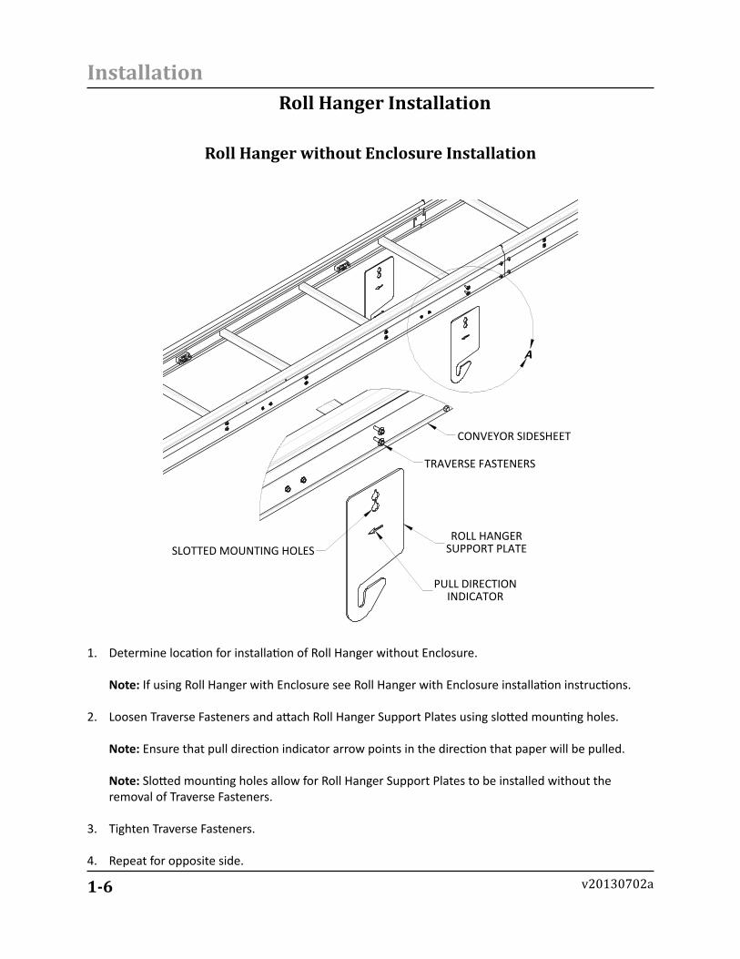
Roll Hanger Installation
A
DETAIL A SCALE 2 : 13
ROLL HANGERSUPPORT PLATE
TRAVERSE FASTENERS
CONVEYOR SIDESHEET
PULL DIRECTIONINDICATOR
SLOTTED MOUNTING HOLES
1. Determine location for installation of Roll Hanger without Enclosure. Note: If using Roll Hanger with Enclosure see Roll Hanger with Enclosure installation instructions.
2. Loosen Traverse Fasteners and attach Roll Hanger Support Plates using slotted mounting holes. Note: Ensure that pull direction indicator arrow points in the direction that paper will be pulled. Note: Slotted mounting holes allow for Roll Hanger Support Plates to be installed without the removal of Traverse Fasteners.
3. Tighten Traverse Fasteners.
4. Repeat for opposite side.
Roll Hanger without enclosure Installation
1-7
Installation
v20130702a
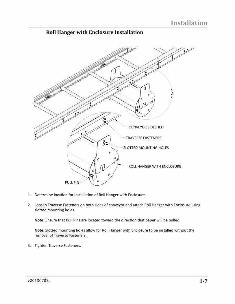
Roll Hanger with enclosure Installation
A
CONVEYOR SIDESHEET
TRAVERSE FASTENERS
ROLL HANGER WITH ENCLOSURE
PULL PIN
SLOTTED MOUNTING HOLES
1. Determine location for installation of Roll Hanger with Enclosure.
2. Loosen Traverse Fasteners on both sides of conveyor and attach Roll Hanger with Enclosure using slotted mounting holes. Note: Ensure that Pull Pins are located toward the direction that paper will be pulled. Note: Slotted mounting holes allow for Roll Hanger with Enclosure to be installed without the removal of Traverse Fasteners.
3. Tighten Traverse Fasteners.

1-8
Installation
v20130702a
Support Hanger assembly Installation
A
ROLL HANGERSUPPORT PLATE
SUBSEQUENTTRAVERSE
STARTINGTRAVERSE
NOTE: ROLL HANGER WITHOUT ENCLOSURESHOWN FOR ILLUSTRATION PURPOSES ONLYMAY BE REPLACED WITH ROLL HANGER WITHENCLOSURE IN SOME INSTALLATIONS.
CONVEYOR SIDESHEET
TRAVERSE FASTENERS
SLOTTED MOUNTING HOLES SUPPORT HANGERMOUNTING PLATE
1. Locate first traverse downstream from installed Roll Hanger.
2. Loosen Traverse Fasteners and attach Support Hanger Mounting Plate using slotted mounting holes. Note: Slotted mounting holes allow for Support Hanger Mounting Plates to be installed without the removal of Traverse Fasteners
3. Tighten Traverse Fasteners.
4. Repeat for opposite side.
1-9
Installation
v20130702a
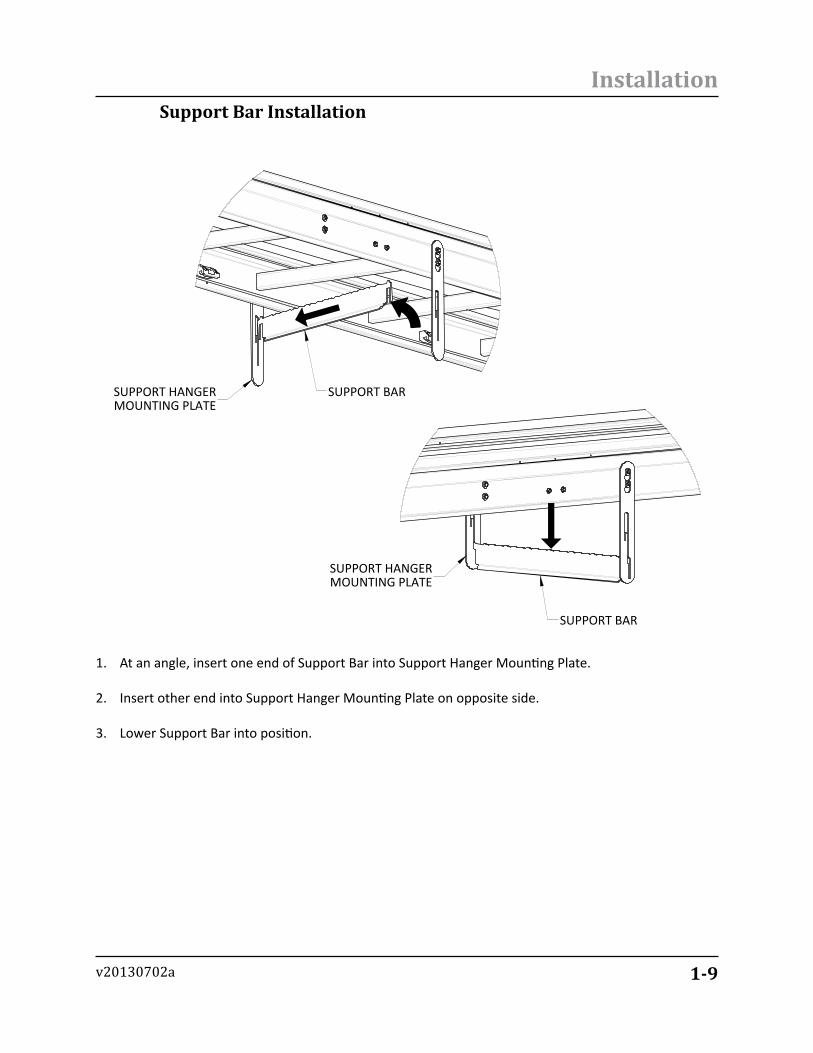
1. At an angle, insert one end of Support Bar into Support Hanger Mounting Plate.
2. Insert other end into Support Hanger Mounting Plate on opposite side.
3. Lower Support Bar into position.A
SUPPORT BARSUPPORT HANGERMOUNTING PLATE
B
SUPPORT HANGERMOUNTING PLATE
SUPPORT BAR
Support Bar Installation

1-10
Installation
v20130702a
lock Bar Installation
1. At an angle, insert one end of Lock Bar into Support Hanger Mounting Plate.
2. Insert other end into Support Hanger Mounting Plate on opposite side.
3. Lower Lock Bar into position.
A
LOCK BARSUPPORT HANGERMOUNTING PLATE
B
LOCK BAR
SUPPORT HANGERMOUNTING PLATE
1-11
Installation
v20130702a
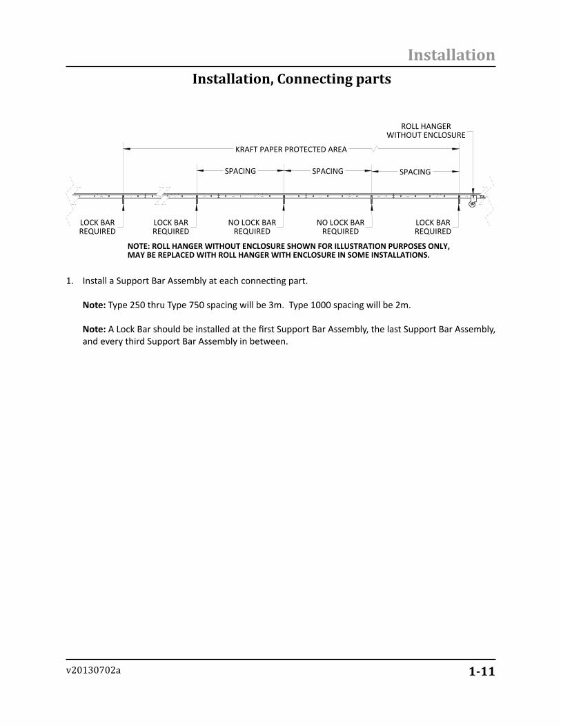
Installation, Connecting parts
1. Install a Support Bar Assembly at each connecting part. Note: Type 250 thru Type 750 spacing will be 3m. Type 1000 spacing will be 2m. Note: A Lock Bar should be installed at the first Support Bar Assembly, the last Support Bar Assembly, and every third Support Bar Assembly in between.
SPACING SPACING SPACING
KRAFT PAPER PROTECTED AREA
ROLL HANGERWITHOUT ENCLOSURE
LOCK BARREQUIRED
NO LOCK BARREQUIRED
NO LOCK BARREQUIRED
LOCK BARREQUIRED
LOCK BARREQUIRED
NOTE: ROLL HANGER WITHOUT ENCLOSURE SHOWN FOR ILLUSTRATION PURPOSES ONLY,MAY BE REPLACED WITH ROLL HANGER WITH ENCLOSURE IN SOME INSTALLATIONS.

1-12
Installation
v20130702a
Installation, Bend Unit
EXTERNAL TRAVERSE
ROLL HANGERSUPPORT PLATES
INTERNALTRAVERSE
SUPPORT HANGER ASSEMBLYLOCK BAR REQUIRED
TYPICAL OF ALL INTERNAL TRAVERSES
KRAFT PAPER
PROTECTED AREA
BEND UNIT
NEXT PROTECTED AREA
NOTE: ROLL HANGER WITHOUTENCLOSURE SHOWN FOR
ILLUSTRATION PURPOSES ONLY,MAY BE REPLACED WITH ROLL HANGER WITH ENCLOSURE IN
SOME INSTALLATIONS
Conveyor Type Degree of Bend Number of Internal Traverses
25045 390 3
35045 490 4
50045 490 5
75045 490 7
100045 590 9
2. If a Bend Unit is encountered, install Support Bar Assemblies and Lock Bar at each internal traverse on Bend Unit. Note: Refer to the Support Hanger Assembly Installation, Bend Unit section of this manual for instructions on how to install Support Hanger Assembly in a Bend Unit. Note: Refer to the chart above to determine the number of Support Bar Assemblies and Lock Bars required for the Bend Unit.
3. To continue, Install another Roll Hanger on first connecting part traverse after Bend Unit.
4. Install a Support Bar Assembly with Lock Bar on traverse after Roll Hanger.

1-13
Installation
v20130702a
A
TRAVERSE FASTENERS
RED CAPPING SUPPORT
SUPPORT HANGERMOUNTING PLATE
BEND UNIT
RED CAPPINGSUPPORT SCREW
DOCUMENTATION
Dim
ensio
ns su
bjec
t to
chan
ge w
ithou
t not
ifica
tion.
Date:5/9/2013
135 Corporate Drive SWCleveland, TN 37311(423) 709-1000 Phone(423) 709-1001 Fax
Support Hanger assembly Insallation, Bend Unit
1. Remove Traverse Fasteners and Red Capping Support Screw.
2. Place Support Hanger Mounting Plate behind Red Capping Support and attach using Traverse Fasteners.
3. Install Red Capping Support Screw.
4. Install Support Bar (Refer to Support Bar Installation Section).
5. Install Lock Bar (Refer to Lock Bar Installation Section).

2-1
System Operation
v20130702a
SeCTIOn 2 SYSTem OpeRaTIOn
Drip Canopy Recommended Paper SpecificationsConveyor Type Paper Weight Paper Width
250 30# 9-in350 40# 15-in500 40# 20-in750 50# 30-in1000 50# 40-in
Recommended Kraft paper Weight and Width
Note: Be sure to observe all Lockout-Tagout procedures prior to installing Kraft Paper Roll or pulling paper through system.
Note: If Roll Hanger without Enclosure is installed Kraft Paper Roll should be removed or protected during conveyor operation to ensure the integrity of the paper roll.
Note: If Roll Hanger with Enclosure is installed, the enclosure should be closed during conveyor operation to ensure the integrity of the paper roll.
(Customer Supplied)

2-2
System Operation
v20130702a
ROLLAXLE
PAPERROLL
PAPERROLL
ROLLAXLE
SHAFTCOLLAR
A
ROLLAXLE
SHAFTCOLLAR ROLL HANGER
SUPPORT PLATE
PAPERROLL
CONNECTING PART
SHAFTCOLLAR
SHAFT COLLARFASTENERS
ENLARGED FOR CLARITY
1. Feed Roll Axle through Paper Roll and install Shaft Collars. Note: Ensure that Shaft Collar Fasteners are tightened before lifting Paper Roll into position. Improper installation of Shaft Collars could lead to Paper Roll sliding out of assembly.
2. Lift Paper Roll with Roll Axle and place on Roll Hanger Support Plates.
Installing Kraft paper Roll, Roll Hanger without enclosure

2-3
System Operation
v20130702a
Installing Kraft paper Roll, Roll Hanger with enclosure
A
ROLLAXLE
PAPERROLL
SHAFTCOLLAR
ROLLAXLE PAPER
ROLL
B
ROLLAXLE
SHAFTCOLLAR
PAPER ROLL
1. Remove Pull Pins and open Roll Hanger with Enclosure.
2. Feed Roll Axle through Paper Roll and install Shaft Collars. Note: Ensure that Shaft Collar Fasteners are tightened before lifting Paper Roll into position. Improper installation of Shaft Collars could lead to Paper Roll sliding out of assembly.
3. Lift Paper Roll with Roll Axle and place in groove on Roll Hanger with Enclosure.
4. If desired, close Roll Hanger with Enclosure and reinstall Pull Pins.

2-4
System Operation
v20130702a
A
B
SUPPORT HANGER ASSEMBLY
LOCK BAR
UNLOCKED POSITION
SUPPORT HANGER ASSEMBLY
LOCK BAR
LOCKED POSITION
1. Move all Lock Bars to their unlocked position.
lock Bar positions

2-5
System Operation
v20130702a
pulling paper Through System
A
BEGINNING A FOLD
B
COMPLETING A FOLD
KRAFT PAPERFOLD POSITIONS
BEND UNIT
INCOMINGKRAFT PAPER KRAFT PAPER END
2. With Lock Bars in their unlocked position, pull the Kraft Paper through system by feeding it through each Hanger Support Assembly making certain the Kraft Paper goes underneath each Lock Bar.
3. If a Bend Unit is encountered, fold Craft Paper on inside radius of Bend Unit and hold in position with Lock Bars.

3-1
Component Details
v20130702a
SeCTIOn 3 COmpOnenT DeTaIlS

3-2
Component Details
v20130702a
3
2 1
ITEM NO. DRAWING NO. PART NO. DESCRIPTION T250 T350 T500 T750 T10001 12S A 140 02A Roll Axle T250 1 - - - -1 12S A 130 02A Roll Axle T350 - 1 - - -1 12S A 120 02A Roll Axle T500 - - 1 - -1 12S A 110 02A Roll Axle T750 - - - 1 -1 12S A 100 02A Roll Axle T1000 - - - - 12 12S A 100 01A Roll Hanger 2 2 2 2 2
3 6436K360 Shaft Collar, 3/4" 2 2 2 2 2
Roll Hanger without Enclosure, T250 - T1000Conveyor Type Part Number Drawing Number Description
250 -- 12S A 140 00A Roll Hanger without Enclosure T250350 -- 12S A 130 00A Roll Hanger without Enclosure T350500 -- 12S A 120 00A Roll Hanger without Enclosure T500750 -- 12S A 110 00A Roll Hanger without Enclosure T750
1000 -- 12S A 100 00A Roll Hanger without Enclosure T1000
Roll Hanger without enclosure, T250 - T1000

3-3
Component Details
v20130702a
12
ITEM NO. DRAWING NO. PART NO. DESCRIPTION T250 T350 T500 T750 T10001 12S A 200 01A Support Hanger 2 2 2 2 22 12S A 240 02A Support Bar T250 1 - - - -2 12S A 230 02A Support Bar T350 - 1 - - -2 12S A 220 02A Support Bar T500 - - 1 - -2 12S A 210 02A Support Bar T750 - - - 1 -2 12S A 200 02A Support Bar T1000 - - - - 1
Support Hanger Assembly, T250 - T1000Conveyor Type Part Number Drawing Number Description
T250 -- 12S A 240 00A Support Hanger Assembly T250T350 -- 12S A 230 00A Support Hanger Assembly T350T500 -- 12S A 220 00A Support Hanger Assembly T500T750 -- 12S A 210 00A Support Hanger Assembly T750
T1000 -- 12S A 200 00A Support Hanger Assembly T1000
Support Hanger assembly, T250 - T1000

3-4
Component Details
v20130702a
Roll Hanger with enclosure T250 - T1000
ITEM NO. DRAWING NO. PART NO. DESCRIPTION T250 T350 T500 T750 T10001 12S A 340 02B Roll Closure Top T250 1 - - - -1 12S A 330 02B Roll Closure Top T350 - 1 - - -1 12S A 320 02B Roll Closure Top T500 - - 1 - -1 12S A 310 02B Roll Closure Top T750 - - - 1 -1 12S A 300 02B Roll Closure Top T1000 - - - - 1
2 12S A 300 03B Roll Closure Bottom T1000 - - - - 12 12S A 310 03B Roll Closure Bottom T750 - - - 1 -2 12S A 320 03B Roll Closure Bottom T500 - - 1 - -2 12S A 330 03B Roll Closure Bottom T350 - 1 - - -2 12S A 340 03B Roll Closure Bottom T250 1 - - - -3 12S A 300 01B Roll Hanger 2 2 2 2 2
4 12S A 300 04A Pivot Plate 2 2 2 2 25 12S A 140 02A Roll Axle T250 1 - - - -5 12S A 130 02A Roll Axle T350 - 1 - - -5 12S A 120 02A Roll Axle T500 - - 1 - -5 12S A 110 02A Roll Axle T750 - - - 1 -5 12S A 100 02A Roll Axle T1000 - - - - 16 F8-7-8-3-8 #10-32 x 1/2" Hex Bolt, Stainless 2 2 2 2 27 F8-7-19-2-10 1/4-20 x 5/8" Hex Bolt, Stainless 2 2 2 2 28 F8-29-19-2-0 1/4-20 Nylock Nut, Stainless 2 2 2 2 2
9 94975A366 Pull Pin 2 2 2 2 210 6436K360 Shaft Collar, 3/4" 2 2 2 2 211 F8-29-8-3-0 #10-32 Nylock Nut, Stainless 2 2 2 2 2

3-5
Component Details
v20130702a
9
3
1
10
5
4
2
7 8
611
Roll Hanger with Enclosure T250 - T1000Conveyor Type Part Number Drawing Number Description
250 -- 12S A 340 00B Roll Hanger with Enclosure T250350 -- 12S A 330 00B Roll Hanger with Enclosure T350500 -- 12S A 320 00B Roll Hanger with Enclosure T500750 -- 12S A 310 00B Roll Hanger with Enclosure T750
1000 -- 12S A 300 00B Roll Hanger with Enclosure T1000
4-1
General Information
v20130702a
SeCTIOn 4 GeneRal InfORmaTIOn
lubing Contact Information
Lubing Systems, L.P.135 Corporate Drive SWCleveland, TN 37311 USA423 709.1000 telephone866 289.3237 toll-free fax
www.lubingusa.com Lubing Systems, L.P. USA [email protected] General Information [email protected] Customer Service/Order [email protected] Technical Support Requests
4-2
General Information
v20130702a
lubing Regional Sales Contact Information
All technical content in this manual is subject to change.
Contact your local Lubing Distributor or Representative for additionalinformation regarding Lubing products.
Northeast/CanadaGEORGE BAILEYCell: (540) 908-8899Fax: (540) 433-7400E-mail: [email protected]
MA,VT, NH, ME, RI, CT, NY, NJ, PA, DE, MD, VA, WV, NC, MI, OHEast Canada: MB, ON, QC, NB, NL, PEI
Midwest/CanadaSTEVE KUYKENDALLCell: (469) 908-8899Fax: (540) 433-7400E-mail: [email protected]
AK, AR, CO, KS, MO, MT, ND, NE, NM, OK, SD, TX, UT, WYWest Canada: AB, SK, BC, YT, NT
West CoastLARRY HOLTCell: (479) 236-2673Fax: (479) 750-3046E-mail: [email protected]
AZ, CA, ID, NV, OR, UT, WA, HI
International SalesKURT HUTTCell: (432) 464-0500Fax: (423) 709-1001E-mail: [email protected]
LUBING Systems, L.P.135 Corporate Drive, SWCleveland, TN 37312 - USATel: (423) 709-1000Fax: (423) 709-1001E-mail: [email protected]: [email protected]
SoutheastBARRY DUTTONCell: (205) 612-5625Fax: (240) 368-8784E-mail: [email protected]
AL, FL, GA, KY, IN, MS, LA, SC, TN

4-3
General Information
v20130702a

All technical content in this manual is subject to change.
Contact your local Lubing Distributor or Representative for additionalinformation regarding Lubing products.
Northeast/CanadaGEORGE BAILEYCell: (540) 908-8899Fax: (540) 433-7400E-mail: [email protected]
MA,VT, NH, ME, RI, CT, NY, NJ, PA, DE, MD, VA, WV, NC, MI, OHEast Canada: MB, ON, QC, NB, NL, PEI
Midwest/CanadaSTEVE KUYKENDALLCell: (469) 908-8899Fax: (540) 433-7400E-mail: [email protected]
AK, AR, CO, KS, MO, MT, ND, NE, NM, OK, SD, TX, UT, WYWest Canada: AB, SK, BC, YT, NT
West CoastInternational SalesKURT HUTTCell: (432) 464-0500Fax: (423) 709-1001E-mail: [email protected]
AZ, CA, ID, NV, OR, UT, WA, HI
LUBING Systems, L.P.135 Corporate Drive, SWCleveland, TN 37312 - USATel: (423) 709-1000Fax: (423) 709-1001E-mail: [email protected]: [email protected]
SoutheastBARRY DUTTONCell: (205) 612-5625Fax: (240) 368-8784E-mail: [email protected]
AL, FL, GA, KY, IN, MS, LA, SC, TN