drivers manual uk - ge0mlib · drivers and interfacing manual qinsy versions 7.x prepared by:...
TRANSCRIPT

DRIVERS AND INTERFACING MANUAL
QINSy Versions 7.x
Prepared by:
Quality Positioning Services bv Huis ter Heideweg 16
3705 LZ, ZEIST The Netherlands
General Tel.: +31- (0)30 - 6941200 Support Tel: +31 - (0)30 - 6941220
Fax : +31- (0)30 - 6923663 QINSy home page : http://www.qps.nl
e-mail : [email protected]

QINSy Drivers And Interfacing Manual Page 2
Prepared by: QPS, Zeist, The Netherlands Printed: Wed, 29 September, 2004
(This page intentionally left blank)

QINSy Drivers And Interfacing Manual Page 3
Prepared by: QPS, Zeist, The Netherlands Printed: Wed, 29 September, 2004
TABLE OF CONTENTS 1. INTERFACING...................................................................................................................................11 1.1 Introduction........................................................................................................................................... 11 1.2 General Interfacing Remarks ................................................................................................................ 11 1.3 Driver Input/Output Testing ................................................................................................................. 12 2. INPUT/OUTPUT DEVICES ..............................................................................................................13 2.1 INTERFACE CARDS .......................................................................................................................... 13
2.1.1 GTEK PCSS-8IA................................................................................................................... 13 2.1.2 DigiBoard PC/8e, AccelePort 8e ........................................................................................... 15 2.1.3 DigiBoard PC/16e.................................................................................................................. 19 2.1.4 ADLink NuDaq PCI-7200 Digital I/O Card.......................................................................... 20 2.1.5 ADLink NuDaq PCI-9118DG Digital I/O Card.................................................................... 23
2.2 TRIGGER DEVICES ........................................................................................................................... 25 2.2.1 QPS PPS Adapter .................................................................................................................. 25 2.2.2 QPS Trigger Device MK 2 .................................................................................................... 26 2.2.3 QPS Trigger Device MK 3 .................................................................................................... 28 2.2.4 QPS Trigger Device MK 4 .................................................................................................... 29
3. DRIVERS .............................................................................................................................................31 3.1 PPS SYSTEM DRIVERS..................................................................................................................... 31
3.1.1 Ashtech PPS .......................................................................................................................... 33 3.1.2 DeepC IMU PPS.................................................................................................................... 35 3.1.3 Magnavox PPS ...................................................................................................................... 37 3.1.4 NMEA $GP PPS.................................................................................................................... 39 3.1.5 NMEA ZDA PPS................................................................................................................... 41 3.1.6 NMEA ZDA PPS (No TTL).................................................................................................. 42 3.1.7 NMEA ZDA PPS (Trimble AgGPS)..................................................................................... 43 3.1.8 Novatel GPSCard (TSS POS/MV) PPS ................................................................................ 44 3.1.9 Sercel #T PPS ........................................................................................................................ 48 3.1.10 Aquarius SVAR!M PPS ........................................................................................................ 48 3.1.11 Trimble 4000 PPS.................................................................................................................. 52 3.1.12 Trimble 4000 PPS (Trimble 7400) ........................................................................................ 55
3.2 POSITION NAVIGATION SYSTEM DRIVERS ............................................................................... 57 3.2.1 Aquarius 5000 Series KART / LRK...................................................................................... 59 3.2.2 Aquarius RTK (GPGGA or GPLRK).................................................................................... 60 3.2.3 Ashtech CBEN ($PASHR,CBN)........................................................................................... 67 3.2.4 Ashtech GG24 GPS + GLONASS (Position)........................................................................ 70 3.2.5 AUV/Buoy Tracking (PARADIGM) .................................................................................... 72 3.2.6 Center Source Position .......................................................................................................... 74 3.2.7 DeepC AUV Position ............................................................................................................ 75 3.2.8 DNAVN AUXCOM3 Position .............................................................................................. 76 3.2.9 EIVA NaviPac Position ......................................................................................................... 78 3.2.10 Fugro MRDGPS (PGS DGPS QC Format) ........................................................................... 79 3.2.11 Geotracer 3000 GPS (NMEA $GPGGK) .............................................................................. 80 3.2.12 iXSea GAPS ($PTSAG Message) ......................................................................................... 82 3.2.13 iXSea GAPS ($PTSAG Message) (With UTC) .................................................................... 82 3.2.14 Javad IMU Unit (Position) .................................................................................................... 84 3.2.15 Javad NAVPOS Positioning / Data Link Quality.................................................................. 85 3.2.16 Linked Object Position .......................................................................................................... 87 3.2.17 Naval GPS Data Link (PLO) ................................................................................................. 90 3.2.18 NMEA Position ($--LLQ) ..................................................................................................... 92 3.2.19 NMEA Position (GPGGA).................................................................................................... 92

QINSy Drivers And Interfacing Manual Page 4
Prepared by: QPS, Zeist, The Netherlands Printed: Wed, 29 September, 2004
3.2.20 NMEA Position (GPGGA Ashtech)...................................................................................... 95 3.2.21 NMEA Position (GPGGA Western)...................................................................................... 97 3.2.22 NMEA Position (GPGLL Height=0)..................................................................................... 99 3.2.23 NMEA Position (GPRMC With UTC)................................................................................ 100 3.2.24 NMEA Position + Heading ($--GGA/$--HDT)................................................................... 101 3.2.25 NMEA Position + Heading (CheckSum) ............................................................................ 101 3.2.26 NMEA Position + Heading (No CheckSum........................................................................ 101 3.2.27 POS M/V (NMEA GGA GST GSA + HDT) ...................................................................... 101 3.2.28 Racal BasMon DeltaFix Binary (Fixed E,N)....................................................................... 105 3.2.29 Racal BasMon DeltaFix Binary (False E,N) ....................................................................... 105 3.2.30 Racal BasMon DeltaFix-LR RTCM 6-of-8 / 8-of-8 (Fixed E,N)........................................ 107 3.2.31 Racal BasMon DeltaFix-LR RTCM 6-of-8 / 8-of-8 (False E,N) ........................................ 107 3.2.32 Range Site Data Format (Geodesic) .................................................................................... 109 3.2.33 REDAS – Fish Position ....................................................................................................... 111 3.2.34 REDAS – Vessel Position + Gyro....................................................................................... 111 3.2.35 REDAS – Vessel Position + Gyro + Depth......................................................................... 111 3.2.36 REMUS AUV ($CARXD) .................................................................................................. 112 3.2.37 RWSLod (0 Message) ......................................................................................................... 115 3.2.38 Sercel Axyle (0 Message) No PPS ...................................................................................... 115 3.2.39 Seatex Integrated GPS / GLONASS (NMEA GNS Format)............................................... 117 3.2.40 Sercel 103 NMEA Position (ZDA & GLL)......................................................................... 118 3.2.41 Sercel 103 NMEA Position ($GPGGA) .............................................................................. 119 3.2.42 Sercel Aquarius RTK (GPGGA) ......................................................................................... 121 3.2.43 Shallow Water Range Format #2......................................................................................... 122 3.2.44 Simrad HPR LBL (Position Output) ................................................................................... 123 3.2.45 Sonardyne APS3 (Position Output) ..................................................................................... 125 3.2.46 Sonardyne LUSBL (LBL / USBL, V5 / V6) ....................................................................... 127 3.2.47 Subsea Telemetry Format .................................................................................................... 129 3.2.48 Syledis SR3 Position (Position | Heading | Speed).............................................................. 131 3.2.49 Trimble 4000 (ASCII Printout) ........................................................................................... 132 3.2.50 Trimble 4000 (ASCII Printout) DGPS Check ..................................................................... 132 3.2.51 Trimble 4000 (ASCII Printout) RTK Check ....................................................................... 132 3.2.52 Trimble TSIP Position ......................................................................................................... 133 3.2.53 UDI-NAV Header (Heading | Position)............................................................................... 134 3.2.54 WinSocket NMEA Position (GPGGA) ............................................................................... 137
3.3 GYRO’S AND COMPASSES SYSTEM DRIVERS......................................................................... 139 3.3.1 Digilog (ASCII)................................................................................................................... 141 3.3.2 Digilog (Modified Anschutz) .............................................................................................. 141 3.3.3 Gyrocompass (Binary Heading) .......................................................................................... 143 3.3.4 iXSea /Photonetics Octans MRU ($HEHDT) ..................................................................... 144 3.3.5 Javad AT4 or IMU Unit (Heading) ..................................................................................... 146 3.3.6 KVH ROV GyroTrac (Heading) ......................................................................................... 148 3.3.7 Litef Gyro LFK95 (Binary) (Heading) ................................................................................ 149 3.3.8 NMEA Anschutz (HEHCC) ................................................................................................ 150 3.3.9 NMEA Gyrocompass (HEHDT) ......................................................................................... 150 3.3.10 NMEA Magnetic Heading (HDG/HDM/HCC/HCD) ......................................................... 150 3.3.11 NMEA True Heading Gyrocompass (HDG/HDT).............................................................. 150 3.3.12 SeaEye Boxer ROV (Heading)............................................................................................ 151 3.3.13 SG-Brown 1000-A Gyrocompass (ASCII Heading) ........................................................... 153 3.3.14 Sperry Gyrocompass (ASCII Heading) ............................................................................... 154 3.3.15 UDI Nav Header Heading ................................................................................................... 155
3.4 PITCH, ROLL AND HEAVE SENSOR DRIVERS.......................................................................... 157 3.4.1 Atlas Dynabase C R-P-H (0.0055 deg)................................................................................ 159 3.4.2 Atlas Dynabase C R-P-H (0.0100 deg)................................................................................ 159 3.4.3 Hippy Datawell Piro MRU .................................................................................................. 160

QINSy Drivers And Interfacing Manual Page 5
Prepared by: QPS, Zeist, The Netherlands Printed: Wed, 29 September, 2004
3.4.4 iXSea /Photonetics Octans MRU ($PHTRH / $PHTRO).................................................... 161 3.4.5 iXSea Phins standard ($HEHDT) / ($PIXSE,ATITUDE, ~POSITI, ~SPEED_)................ 163 3.4.6 Javad AT4 or IMU Unit (R-P)............................................................................................. 166 3.4.7 KVH ROV GyroTrac (Pitch and Roll) ................................................................................ 168 3.4.8 Litef Gyro LFK95 (Binary) (Pitch-Roll) ............................................................................. 169 3.4.9 Seatex Seapath MRU Binary Standard................................................................................ 170 3.4.10 Seatex Seapath MRU Binary Format11 .............................................................................. 170 3.4.11 Seatex Seapath MRU NMEA ($PSXN) .............................................................................. 172 3.4.12 Seatex Seapath MRU Sounder Sentence ............................................................................. 174 3.4.13 Sercel 230 Heading, Roll and Pitch..................................................................................... 175 3.4.14 Simrad EM1000 (R-P-H)..................................................................................................... 177 3.4.15 Simrad EM3000 (R-P-H)..................................................................................................... 177 3.4.16 TSS 320 / 335 / DMS-05 (R-P-H) ....................................................................................... 179
3.5 USBL SYSTEM DRIVERS ............................................................................................................... 181 3.5.1 Crane Tool VanDerLeun (QATT/QXYZ) (dX dY dZ) ....................................................... 187 3.5.2 CutterSuction Tool VanDerLeun (dX dY dZ)..................................................................... 191 3.5.3 Dredging Tool (dX dY dZ).................................................................................................. 193 3.5.4 IHC Dredge Monitoring ($PIHC)........................................................................................ 194 3.5.5 iXSea GAPS ($PTSAX Message) ...................................................................................... 198 3.5.6 iXSea GAPS ($PTSAX Message) (With UTC) ................................................................. 198 3.5.7 Nautronics ATS (ASCII) ..................................................................................................... 200 3.5.8 Nautronics ATS (ASCII) (UTC) ........................................................................................ 200 3.5.9 Seatec SmartWire ................................................................................................................ 201 3.5.10 Simrad HiPAP (NMEA Format) ......................................................................................... 202 3.5.11 Simrad HiPAP (400 Format) ............................................................................................... 203 3.5.12 Simrad HPR300 (ASCII)..................................................................................................... 205 3.5.13 Simrad Binary HPR............................................................................................................. 207 3.5.14 Sonardyne USBL (Surveyors Output) ................................................................................. 209 3.5.15 TrackPoint II........................................................................................................................ 211
3.6 MANUAL LAYBACK SYSTEM DRIVER...................................................................................... 215 3.6.1 Manual Layback .................................................................................................................. 215
3.7 SINGLEBEAM ECHOSOUNDER DRIVERS.................................................................................. 217 3.7.1 Annotation Drivers .............................................................................................................. 220 3.7.2 Deso 15 / 20 / 25 Echosounder ............................................................................................ 227 3.7.3 Deso 25 (With Annotation) ................................................................................................. 229 3.7.4 Bathy UK94 Pressure Sensor (Depth) ................................................................................. 230 3.7.5 Bathy UK94 Pressure Sensor (Altitude).............................................................................. 230 3.7.6 EG&G Sonar System (Depth) ............................................................................................. 231 3.7.7 Elac LAZ 4400 Echosounder .............................................................................................. 232 3.7.8 Elac STG 721 Echosounder................................................................................................. 233 3.7.9 Kaijo Denki PS20R Echosounder........................................................................................ 234 3.7.10 Knudsen 320M (PKEL HF) (With Annotation) .................................................................. 235 3.7.11 Knudsen 320M (PKEL LF) (With Annotation)................................................................... 235 3.7.12 Marimatech E-Sea Sound Echosounder .............................................................................. 237 3.7.13 Odom Echotrac/Digitrace (High Freq | Low Freq | Single Freq) ........................................ 238 3.7.14 Odom Echotrac (With Annotation and STX | no STX)....................................................... 238 3.7.15 Raytheon (Single Frequency) .............................................................................................. 238 3.7.16 NMEA (DPT,DBT,DBS) (With Annotation) ...................................................................... 240 3.7.17 Simrad EA-Series ASCII Telegram (With Annotation) ...................................................... 240 3.7.18 Simrad EA-Series ASCII Telegram..................................................................................... 243 3.7.19 Simrad EA-Series ASCII Telegram (With UTC) ................................................................ 243 3.7.20 Simrad EA-Series (Socket).................................................................................................. 244 3.7.21 Simrad EA-Series (Socket) (With UTC) ............................................................................ 244 3.7.22 Sweep Depth (Imtech DMS 3500) ...................................................................................... 248
3.8 MULTI-TRANSDUCER ECHOSOUNDER DRIVERS ................................................................... 249

QINSy Drivers And Interfacing Manual Page 6
Prepared by: QPS, Zeist, The Netherlands Printed: Wed, 29 September, 2004
3.8.1 Navitronic (DPP 2000) ........................................................................................................ 251 3.8.2 STN Atlas Bomasweep........................................................................................................ 253
3.9 MULTIBEAM ECHOSOUNDER DRIVERS ................................................................................... 255 3.9.1 Aran Rut Bar........................................................................................................................ 260 3.9.2 L3 Communications Seabeam 1180 / 1885 ......................................................................... 261 3.9.3 Marimatech E-Sea Swath 501 (5 Channel echosounder) .................................................... 264 3.9.4 Odom Echoscan................................................................................................................... 265 3.9.5 Odom Echoscan XTF .......................................................................................................... 265 3.9.6 Reson Seabat 81xx/900x (Serial) [XTF] ............................................................................. 267 3.9.7 Reson Seabat 81xx/900x (Network) [XTF]......................................................................... 268 3.9.8 Reson Seabat 7K (Network) ................................................................................................ 270 3.9.9 Simrad EM1000 (X-Y-Z Format)........................................................................................ 272 3.9.10 Simrad EM1000 (X-Y-Z Format) (No UTC) ...................................................................... 272 3.9.11 Simrad EM300x (R-Theta Format) ..................................................................................... 275 3.9.12 Simrad EM3000 (X-Y-Z Format)........................................................................................ 275 3.9.13 Simrad EM3000D Head II (X-Y-Z Format)........................................................................ 275 3.9.14 Simrad EM3000D Head II (R-Theta Format) ..................................................................... 275 3.9.15 Simrad EM3000 (R-Theta Format / D) ............................................................................... 275 3.9.16 Simrad EM3000D Head II (R-Theta Fmt / D)..................................................................... 275 3.9.17 Simrad EM300x XTF (R-Theta Format)............................................................................. 275 3.9.18 Simrad EM300x XTF (X-Y-Z Format) ............................................................................... 275 3.9.19 Simrad EM1002 (R-Theta Format) ..................................................................................... 275 3.9.20 Simrad Mesotech MS 971 / MS 990 ................................................................................... 285 3.9.21 Simrad Mesotech SM2000 .................................................................................................. 287 3.9.22 SMD ROV Cable Tracker, Gyro Heading, Depth & Altitude, Cable Data ......................... 290 3.9.23 STN Atlas Fansweep ........................................................................................................... 292 3.9.24 TSS 340 PipeTracker, ROV Altitude, Depth of Cover, Signal Strength............................. 295 3.9.25 TSS 350 CableTracker, ROV Altitude, Depth of Cover, Signal Strength........................... 295 3.9.26 TSS 340/350 Tracker (Ignore Offset Quality)..................................................................... 295 3.9.27 Tritech SeaKing SCU Master (Slot 2) ................................................................................. 298 3.9.28 Tritech SeaKing SCU Slave (Slot 3) ................................................................................... 298 3.9.29 Ulvertech Profiler (Head 1) ................................................................................................. 302 3.9.30 Ulvertech Profiler (Head 2) ................................................................................................. 302 3.9.31 Ulvertech Pipe / Cable Tracker............................................................................................ 307
3.10 SIDESCAN SONAR DRIVERS ........................................................................................................ 311 3.10.1 Analog Sidescan [PCI card] (0-5V. Pos. Trigger) ............................................................... 315 3.10.2 Analog Sidescan [PCI card] (0-5V. Neg. Trigger) .............................................................. 315 3.10.3 Klein 2000 ........................................................................................................................... 317 3.10.4 Klein 2000 QPS Simulator .................................................................................................. 317 3.10.5 Reson Seabat 81xx/900x (ß) (Network) .............................................................................. 320 3.10.6 Reson Seabat 81xx/900x (ß) (Network) XTF-Snippets....................................................... 320 3.10.7 Reson Seabat 7K (Network) ................................................................................................ 322 3.10.8 Simrad EM3000 Seabed Image ........................................................................................... 323 3.10.9 Simrad EA-Series Sidescan ................................................................................................. 324 3.10.10 Simrad EA-Series Sidescan (With UTC) ............................................................................ 324
3.11 UNDERWATER SENSOR DRIVERS .............................................................................................. 331 3.11.1 DeepC AUV (Depth & Altitude)......................................................................................... 333 3.11.2 DSSI ROV Depth (NMEA $--DPT).................................................................................... 334 3.11.3 Eurosense Realtime Draught ............................................................................................... 335 3.11.4 Eurosense Realtime Draught (UTC).................................................................................... 335 3.11.5 Hyspec OSP Bathy (ROV Depth or Altitude) ..................................................................... 336 3.11.6 ISIS (ROV Depth and Altitude) (ROV Gyro) (Cable Out) ................................................. 337 3.11.7 Klein2000 SSS Info (With Annotation) .............................................................................. 338 3.11.8 Klein595 SSS (Altitude) (With Annotation) ....................................................................... 340 3.11.9 Magnetometer (Geometrics G880) ...................................................................................... 342

QINSy Drivers And Interfacing Manual Page 7
Prepared by: QPS, Zeist, The Netherlands Printed: Wed, 29 September, 2004
3.11.10 Smart SV (AML, ASCII) (Active) ...................................................................................... 343 3.11.11 Sweep (Imtech DMS 3500) ................................................................................................. 345 3.11.12 Tritech SCU-3 SeaKing (Passive | UTC) ............................................................................ 346 3.11.13 Tritech SCU-3 Winson V4 (Passive | UTC)........................................................................ 346 3.11.14 Tritech SCU-3 Environmetal Data (Passive | UTC) ............................................................ 346 3.11.15 Ulvertech Bathy (Depth & Altitude) ................................................................................... 350 3.11.16 Ulvertech Profiler (OSP Data)............................................................................................. 352
3.12 SOUND VELOCITY PROFILE SYSTEM DRIVERS...................................................................... 355 3.12.1 Depth SV (ASCII Format)................................................................................................... 357 3.12.2 Depth SV (EMS00 Format) ................................................................................................. 357 3.12.3 Depth SV Temp Cond (HIPAP or EM3000 Format) .......................................................... 357 3.12.4 Depth SV Temp Salinity (EMS12 Format) ......................................................................... 357 3.12.5 Depth SV Temp (AML or EM1000 Format)....................................................................... 357 3.12.6 Depth SV (DeepC AUV)..................................................................................................... 358
3.13 SPEED LOG DRIVERS..................................................................................................................... 359 3.13.1 EDO 3050 Dopplerlog......................................................................................................... 363 3.13.2 EDO 3050 Dopplerlog (Tideway) ....................................................................................... 363 3.13.3 NAVIKNOT III / EM200 Speed Log.................................................................................. 364 3.13.4 iXSea /Photonetics Octans MRU ($PHSPD) ...................................................................... 365 3.13.5 RDI Doppler BottomTrack Speed (BIN PD0)..................................................................... 366 3.13.6 RDI Doppler BottomTrack Speed (PD6) ............................................................................ 369 3.13.7 RDI Doppler BottomTrack (Remote Cherry)...................................................................... 371
3.14 TIDE GAUGE DRIVERS .................................................................................................................. 373 3.14.1 DCI SBU92 Tide Gauge (Selected Data) ............................................................................ 377 3.14.2 DCI SBU92 Tide Gauge (Snelpeil Data)............................................................................. 377 3.14.3 Digitrans Radio Tide Gauge (PAH) .................................................................................... 379 3.14.4 Hymedis Tide ...................................................................................................................... 380 3.14.5 Kuhnt Pegel Tide Gauge...................................................................................................... 382 3.14.6 Pacific Crest Tide Gauge..................................................................................................... 384 3.14.7 Sonar Research LPM23 Tide Gauge ................................................................................... 385 3.14.8 Valeport 700 Tide Gauge .................................................................................................... 387 3.14.9 Van Essen RGC920 Tide Gauge ......................................................................................... 388 3.14.10 Vyner Medway Radio Tide Gauge MK I ............................................................................ 390 3.14.11 Vyner Medway Radio Tide Gauge MK II ........................................................................... 390
3.15 SURFACE NAVIGATION SYSTEM DRIVERS ............................................................................. 393 3.15.1 Artemis Range & Bearing (ASCII) ..................................................................................... 397 3.15.2 Artemis Range & Bearing (KA-BCD (0.1))........................................................................ 397 3.15.3 Artemis Range & Bearing (KA-BCD (0.01))...................................................................... 397 3.15.4 AUV/Buoy Tracking (PARADIGM) .................................................................................. 400 3.15.5 Cable Counter (Dynapar, Sidescan Winch)......................................................................... 403 3.15.6 Cable Counter (Red Lion) ................................................................................................... 405 3.15.7 Cable Counter Payout (MD Totco)...................................................................................... 406 3.15.8 Cable Counter Tension / Speed (MD Totco) ....................................................................... 406 3.15.9 DCI Minilir-Fennel.............................................................................................................. 407 3.15.10 Geodimeter 600 ................................................................................................................... 409 3.15.11 Geodimeter Aga 140T ......................................................................................................... 412 3.15.12 Leica TPS1000 Series Theodolite (GeoCOM) .................................................................... 414 3.15.13 MDL Fanbeam Mk III R & B (MDL Standard) .................................................................. 417 3.15.14 MDL Fanbeam Mk III R & B (Simrad Binary)................................................................... 417 3.15.15 GECO Trinav rGPS ............................................................................................................. 419 3.15.16 NavAnalog Analog to Digital Converter ............................................................................. 421 3.15.17 ParkerPDFX Stepping Drive Driver.................................................................................... 423 3.15.18 Simrad HPR LBL (Raw data).............................................................................................. 426 3.15.19 Sonardyne PAN (SI/FS format)........................................................................................... 428 3.15.20 Sonardyne PAN (LB format)............................................................................................... 428

QINSy Drivers And Interfacing Manual Page 8
Prepared by: QPS, Zeist, The Netherlands Printed: Wed, 29 September, 2004
3.15.21 WAGO Dynamic Transducer Mounting ............................................................................. 430 3.16 SATELLITE NAVIGATION SYSTEM DRIVERS .......................................................................... 433
3.16.1 Aquarius (Port A) ................................................................................................................ 435 3.16.2 Aquarius (Port B)................................................................................................................. 435 3.16.3 Ashtech ADU2 [old version] ............................................................................................... 437 3.16.4 Ashtech ADU2 Raw Data.................................................................................................... 439 3.16.5 Ashtech G12 GPS Board ..................................................................................................... 439 3.16.6 Ashtech Z12 Raw Data........................................................................................................ 442 3.16.7 Leica MX 9400N (Active Raw Data) .................................................................................. 443 3.16.8 Leica MX 9400N (Passive Raw Data)................................................................................. 444 3.16.9 Magnavox 9212 (Active Raw Data) .................................................................................... 446 3.16.10 Magnavox 9212 (Passive Raw Data)................................................................................... 447 3.16.11 Sercel NR103 (Passive Raw Data) ...................................................................................... 448 3.16.12 Sercel NR203 (Active Raw Data)........................................................................................ 450 3.16.13 Sercel NR203 (Passive Raw Data) ...................................................................................... 452 3.16.14 Trimble 4000 (Active RCI) ................................................................................................. 454 3.16.15 Trimble 7400 RealTime Survey Data.................................................................................. 456 3.16.16 Trimble DSM (TSIP)........................................................................................................... 458 3.16.17 Trimble DSM (TSIP) PosNet .............................................................................................. 459
3.17 DIFFERENTIAL CORRECTIONS SYSTEM DRIVERS................................................................. 461 3.17.1 Aquarius (Port A) ................................................................................................................ 463 3.17.2 Aquarius (Port B)................................................................................................................. 463 3.17.3 NMEA RTCM (DGPRC-DGDDC-DGREF) ...................................................................... 464 3.17.4 RTCM-104 6 of 8 ................................................................................................................ 465 3.17.5 RTCM-104 6 of 8 [Bit-Slipped] .......................................................................................... 465 3.17.6 RTCM-104 8 of 8 ................................................................................................................ 465 3.17.7 Sercel NR103 (Passive Corrections) ................................................................................... 466 3.17.8 Sercel NR203 (Passive Corrections) ................................................................................... 466 3.17.9 Sercel NR203 (Active Corrections)..................................................................................... 466
3.18 OUTPUT SYSTEM DRIVERS.......................................................................................................... 467 3.18.1 6041 Win Socket Output ..................................................................................................... 469 3.18.2 ADCP Lat/Lon & X/Y Position (Node Output | Steered Point) .......................................... 472 3.18.3 ADCP X/Y Position (Node Output | Steered Point) ............................................................ 472 3.18.4 ADCP Lat/Lon Position ($SNGLL) (Node Output | Steered) ............................................. 474 3.18.5 Anchor Output (Network) ................................................................................................... 475 3.18.6 Atlas Deso 15 Annotator (Node Output | Steered Point)..................................................... 476 3.18.7 Atlas Fansweep 20 Output Driver ....................................................................................... 477 3.18.8 AutoPilot Euro500 Output Driver ....................................................................................... 478 3.18.9 AutoPilot RobTrack/STS500 Output Driver ....................................................................... 479 3.18.10 AUXCOM 3 (Position; Age=0) (Survey | WGS84) ............................................................ 480 3.18.11 AUXCOM 3 (Position and Age) (Survey | WGS84)........................................................... 480 3.18.12 AUXCOM 3 (Skewed Position) (Survey | WGS84) ........................................................... 480 3.18.13 Bennex Left Right Indicator ................................................................................................ 482 3.18.14 Coda Navigation Output Driver .......................................................................................... 483 3.18.15 CorrOcean Cathodic Protection System Output Driver....................................................... 484 3.18.16 CorrOcean CP (Steered Point) Output Driver ..................................................................... 484 3.18.17 Echosounder Depth Output ................................................................................................. 485 3.18.18 Fish output to 6041 (WinSocket)......................................................................................... 488 3.18.19 Ballast Nedam X/Y (Local) ................................................................................................. 489 3.18.20 Ballast Nedam X/Y (Steered Point)..................................................................................... 489 3.18.21 GeoCom X-Star ................................................................................................................... 489 3.18.22 GeoLab ESP Annotator (Node Output | Steered Point)....................................................... 491 3.18.23 Geomap (Fish Positions) ..................................................................................................... 492 3.18.24 HOV (HDAS-A) (WinSocket) ............................................................................................ 493 3.18.25 HOV (HDAS-B) (WinSocket)............................................................................................. 493

QINSy Drivers And Interfacing Manual Page 9
Prepared by: QPS, Zeist, The Netherlands Printed: Wed, 29 September, 2004
3.18.26 LAMs Gyro Position output (Node Output | Steered Point)............................................... 495 3.18.27 VOACZ Video Eventing (Steered Point) ........................................................................... 497 3.18.28 ISIS (JD, Soundvelocity, Depth, Fixnumber)...................................................................... 498 3.18.29 ISIS (Start/Stop Logging) .................................................................................................... 498 3.18.30 ISIS (Vessel and Fish Positions) ......................................................................................... 500 3.18.31 REDAS (Vessel and Fish Positions).................................................................................... 500 3.18.32 SMD (Vessel and ROV Positions) ...................................................................................... 500 3.18.33 DOWTY (Vessel and Fish Positions).................................................................................. 500 3.18.34 Naval GPS Data Link (PLO) ............................................................................................... 503 3.18.35 Meteo Report Generator (WMO – SYNOP) ....................................................................... 505 3.18.36 NMEA Autopilot Strings Output Driver ............................................................................. 509 3.18.37 NMEA Autopilot Strings (Steered Point) Output Driver .................................................... 509 3.18.38 NMEA GPGGA-GPVTG (Skewed Position)...................................................................... 513 3.18.39 NMEA GPGGA-GPVTG (Skewed Steered Point) ............................................................. 513 3.18.40 NMEA GPGGA-GPVTG (Steered Point) ........................................................................... 513 3.18.41 NMEA GPGGA ROV Output Driver.................................................................................. 515 3.18.42 PGS NAV Header (Node Output | Steered Point) ............................................................... 516 3.18.43 Pseudo Artemis (Range-Bearing) ........................................................................................ 517 3.18.44 Range Site Data Format (Geodesic) .................................................................................... 519 3.18.45 Seabat 8000 Series UTC Synchroniser................................................................................ 523 3.18.46 Sercel Axyle UTC Synchroniser ......................................................................................... 523 3.18.47 Simrad ADP70X (Position and Waypoints) ........................................................................ 524 3.18.48 Simrad S90 Telegram Output Driver................................................................................... 527 3.18.49 Simrad DP Force Output Driver .......................................................................................... 528 3.18.50 Statoil Data Server Format .................................................................................................. 530 3.18.51 Subsea Telemetry Format Output........................................................................................ 531 3.18.52 Syledis Y/X Position (Fault Quality) (Node Output | Steered Point) .................................. 532 3.18.53 Syledis Y/X Position (Quality) (Node Output | Steered Point) ........................................... 532 3.18.54 Syntrak 480 Output.............................................................................................................. 534 3.18.55 Syntrak 480 Output (Steered) .............................................................................................. 534 3.18.56 Tug Manager ....................................................................................................................... 535 3.18.57 VisualWorks Event Output.................................................................................................. 540 3.18.58 Waypoints - NMEA ECDIS 3500 (WinSocket) .................................................................. 541 3.18.59 Waypoints - NMEA RTE/WPL (Simrad SDP) ................................................................... 543 3.18.60 Waypoints - NMEA WPC (Cegelec DPS 901) ................................................................... 543 3.18.61 Waypoints - NMEA WPL (Serial / Simrad SDP) ............................................................... 543 3.18.62 WinFrog Decoder Output .................................................................................................... 547
3.19 CLOSURE OUTPUT SYSTEM DRIVERS....................................................................................... 549 3.19.1 QPS Fix Generator Mk1 | Mk2 | Mk3 ................................................................................. 551 3.19.2 Knudsen Event Marker ........................................................................................................ 552 3.19.3 Text Annotation................................................................................................................... 553
3.20 AIS SYSTEM DRIVERS ................................................................................................................... 555 3.20.1 AIS Standard VDO/VDM Messages ................................................................................... 557 3.20.2 NMEA Target Messages (TLL/TLB/TTM) ........................................................................ 558
3.21 ARPA SYSTEM DRIVERS............................................................................................................... 559 3.21.1 ARPA 3500 Targets (Network) ........................................................................................... 561
3.22 GUN CONTROLLER DRIVERS ...................................................................................................... 563 3.23 P5/94 GENERATOR DRIVERS........................................................................................................ 565 3.24 MAGNETOMETER DRIVERS......................................................................................................... 567
3.24.1 Magnetometer (Geometrics G880) ...................................................................................... 570 3.24.2 SeaSPY/SeaLINK Standard Format (Passive) .................................................................... 571 3.24.3 SeaSPY/SeaLINK Standard Format (with UTC) (1Hz) ...................................................... 571 3.24.4 SeaSPY/SeaLINK Standard Format (with UTC) (4Hz) ...................................................... 571
3.25 MISCELLANEOUS SYSTEM DRIVERS ........................................................................................ 573 3.25.1 Airpax Tachtrol RPM .......................................................................................................... 575

QINSy Drivers And Interfacing Manual Page 10
Prepared by: QPS, Zeist, The Netherlands Printed: Wed, 29 September, 2004
3.25.2 Anchor Input (Network) ...................................................................................................... 576 3.25.3 Campbell Scientific CR10 Datalogger ................................................................................ 577 3.25.4 DeepC AUV AFS Control ................................................................................................... 579 3.25.5 Draught Measurement System (Imtech DMS 3500) ........................................................... 581 3.25.6 Javad IMU Unit (Sensor Data) ............................................................................................ 582 3.25.7 Magnetometer (Geometrics)................................................................................................ 584 3.25.8 Magnetometer (SeaLINK)................................................................................................... 585 3.25.9 Network Data Logger (UDP Port)....................................................................................... 587 3.25.10 NMEA Miscellaneous (ROT / MWD / MWV), (XDR / MTR), (MTW) ............................ 588 3.25.11 Nortek Aquadopp (3D Velocity, Pressure, Temp, Heading, P+R)...................................... 591 3.25.12 OISTAR FieldBus TimeMaster........................................................................................... 593 3.25.13 Paroscientific SDI-12 Transmitter....................................................................................... 596 3.25.14 Remote Control - De Beers ................................................................................................. 597 3.25.15 RWS Directional Waverider................................................................................................ 599 3.25.16 Standard RMI (1 observation) ............................................................................................. 601 3.25.17 Stappenbaak (RWS) ............................................................................................................ 602 3.25.18 Seatools Grab Excavation System....................................................................................... 603
3.26 GENERIC INPUT/OUTPUT DRIVERS ........................................................................................... 607 3.26.1 Generic Serial Input Driver ................................................................................................. 609 3.26.2 Generic Eventing Driver...................................................................................................... 616 3.26.3 Generic Driver Tables ......................................................................................................... 622
3.27 DRIVER DESCRIPTION TEMPLATE FORM ................................................................................ 627 3.27.1 DB Setup Name ................................................................................................................... 627
LIST OF APPENDICES APPENDIX A: RS-232 Connector Pin Assignments APPENDIX B: RS-422 Connector Pin Assignments TRADEMARK ACKNOWLEDGEMENTS Windows XP / 2000 / NT / 95 is a registered Trademark of the Microsoft Corporation MANUAL OBJECTIVE This manual is intended as a supplement to the QuickStart document, in order to describe special additions to the Acquisition Software. Thereafter, further details can be found in the Online Help that comprises module specific help along with relevant reference material.

QINSy Drivers And Interfacing Manual Page 11
Prepared by: QPS, Zeist, The Netherlands Printed: Wed, 29 September, 2004
1. INTERFACING
1.1 Introduction The Acquisition Software is PC (personal computer) based, comprises a suite of programs built using the MS Visual C++ language, and runs under the Windows NT (WinNT) 32 bit operating systems. The Acquisition Software has a very solid base structure (core elements) upon which various modules can be built to provide the functionality (client applications) needed to perform any type of survey. I/O drivers enable the Acquisition Software to communicate with input and output devices. Each input driver is a separate executable that deciphers the input data string, stripping out and distributing the various pieces of information to the individual Acquisition Software modules needing them. Each output driver is a separate executable that compiles the required output data into a predefined format which can be read and deciphered by an external device or software application. Complete modularity of the Acquisition Software drivers means that additional device drivers can be added to your system without re-compilation of the entire software package. Moreover, drivers for new devices or new output requirements can be added without re-compilation.
1.2 General Interfacing Remarks Any intelligent multi-channel communications card supported by the WinNT/95 operating systems will work with the Acquisition Software. This means you are not limited to communications boards preferred by us, as long as the manufacturer supplies the Windows virtual interface drivers which map the interface ports as standard COM ports (RS-232). Multi-channel communications also includes PCMCIA cards which means the Acquisition Software will run on a notebook style computer. WinNT will support the definition of up to 256 serial COM ports. The cable wiring to a 9-pin COM port and a 25-pin COM port (RS-232) is as follows:
COM DB-9 COM DB-25 Pin Function Pin Function 2 RXD 2 TXD 3 TXD 3 RXD 5 SG 7 SG
For some Acquisition Software drivers, it is important that the wiring is bi-directional. If a device needs handshaking, 9-pin cables can be configured for handshake by connecting 7 RTS and 8 CTS, and 25-pin cables by connecting 4 RTS and 5 CTS. See the driver descriptions.

QINSy Drivers And Interfacing Manual Page 12
Prepared by: QPS, Zeist, The Netherlands Printed: Wed, 29 September, 2004
The usual way to configure the Acquisition Software to use a specific I/O driver is to just add a system to the database. Start the Database Setup module and add the appropriate survey and object details. Thereafter, add a system for each measurement device or output string. Use a unique identification number for each system, complete its name and select the system type from the list. Select the Interfacing tab (select I/O Parameters if necessary) and enter the diver interface parameters. Complete the system configuration by connecting the appropriate observation(s) and node(s), and defining the system parameters. It is important that the Date, Time and Time Zone of the PC are properly set, because some input drivers in the Acquisition Software use these settings to identify the proper date if only a time is decoded. For some measurement devices, in order to be able to use all different types of observations contained in one device output string, more than one system has to be added to the Acquisition Software database, using the same driver name and interface parameters for the different types of systems. Furthermore, some Acquisition Software drivers have a separate driver user interface. Refer to the individual driver descriptions and the release notes for more information. If specific Acquisition Software interfacing remarks are suggested for clarification or completeness, then prescribed or recommended interface parameters, procedure for setting up the Acquisition Software database parameters, procedure for setting up sensor and parameters, cable wiring and connection notes, and/or interface testing notes are given in the individual driver descriptions.
1.3 Driver Input/Output Testing Input/Output can be tested using the I/O Test utility, the HyperTerminal program under WinNT (see Accessories group) or Procomm Plus under MS-DOS, which can also be used to change the settings on certain devices. Just start HyperTerminal, select a COM port and modify the port settings. If a connection is properly configured, data will be displayed. ASCII strings should be easily readable. Recording a sample of ASCII data can be done with all three programs, though recording a sample of binary data should only be done with either the I/O Test utility or Procomm Plus programs. The separate RTCM IO Tester utility can be used to display incoming RTCM-104 type 1/9 and 2 messages. The Acquisition Software Survey (Online) program can also be used to test and verify driver input. The Observation Physics display shows raw data as decoded by the Acquisition Software input drivers, and can be opened without computations configured. When observations are displayed, it is not only an indication that the input string is decoded, but also that the data is distributed within the Acquisition Software. The Positioning System display will show data that has been decoded from the output string of a positioning system. The EchoSounder / Raw Multibeam displays show raw depths from echosounder systems. Finally, the Timeplot display can also show raw observations. Online, with the Controller and I/O modules started, if all I/O is properly configured (device connection, interface port selection and system configuration) the Controller should indicate, with the three status lights, that the three main processes of I/O, Computation and Deskewing are working. You can use the Computation Wizard to configure the computations.

QINSy Drivers And Interfacing Manual Page 13
Prepared by: QPS, Zeist, The Netherlands Printed: Wed, 29 September, 2004
2. INPUT/OUTPUT DEVICES
2.1 INTERFACE CARDS
2.1.1 GTEK PCSS-8IA Last modified: 1997-Oct-10
General Description
GTEK PCSS-8IA Intelligent Super Serial Coprocessor Cards provide 8 independent RS-232 asynchronous serial communication channels per board. Both transmitted and received data is buffered on the board with no overhead on the host computer’s processor. Each PCSS-8IA board occupies only 4 I/O addresses.
Installation Notes
Before installing the board in the PC, a unique I/O port and a memory base address used to map the memory, as well as a shared IRQ number, need to be determined. In order to check all the available options under Windows NT, choose “Programs” - “Administrative Tools” - “Windows NT Diagnostics” from the “Start” menu, and select the “Resources” tab to evaluate both the IRQ numbers and I/O Port addresses which are already used. The example below gives a list of IRQ numbers after the GTEK board has been installed.

QINSy Drivers And Interfacing Manual Page 14
Prepared by: QPS, Zeist, The Netherlands Printed: Wed, 29 September, 2004
Jumper Settings for I/O Port Addresses
Jumper block JB1 selects one of seven base addresses for the PCSS-8IA. In the following list, “ON” means jumper installed between the two pins (sequence 1-2-3). Notice that you need no jumper to use the default. OFF-OFF-OFF for 2E0h; ON-OFF-OFF for 2E4h; OFF-ON-OFF for 210h; ON-ON-OFF for 214h; OFF-OFF-ON for 218h; ON-OFF-ON for 21Ch; OFF-ON-ON for 220h (ON-ON-ON is not allowed).
Jumper Settings for IRQ Selections
Jumper block JB3 selects the desired interrupting function with a single jumper on number 2, 3, 4, 5, or 7.
GTEK Setup and Installation
After the JB1 and JB3 jumpers have been set and the PCSS-8IA interface board has been installed in the PC, the GTEK files have to be installed. In most cases, these files are available on CD-ROM or floppy. If only a ZIP archive is available, e.g. 95NT(1).ZIP, extract all the files in the ZIP file to a temporary directory. Run SETUP.EXE and follow the instructions. After a successful setup, choose “Programs” - “GTEK” - “GTEK” from the “Start” menu and select the appropriate parameters. Press “Enter”, shutdown and restart Windows. The result of the GTEK installation can best be tested by using the HyperTerminal (or GTERM) program.
GTEK Installation Example
An example of a typical GTEK installation is shown below. The I/O address is the default 2E0h using no shorting jumper. The first COM port 10 is chosen to correspond to port 0 on the GTEK expander box.
Note. In case the GTEK installation has NOT been successful, its COM ports must be deleted using the “Settings” - “Control Panel” - “Ports” command from the Windows “Start” menu.

QINSy Drivers And Interfacing Manual Page 15
Prepared by: QPS, Zeist, The Netherlands Printed: Wed, 29 September, 2004
2.1.2 DigiBoard PC/8e, AccelePort 8e Last modified: 1997-May-01
General Description
The Digi PC/8e and AccelePort 8e boards, which are functionally identical, are multi-channel intelligent serial communication boards for computers equipped with at least one 16-bit ISA slot. The CPU of the AccelePort 8e board is a 16-bit 80186 processor. The card is equipped with a 64 Kb of dual-ported high-speed RAM used for the program running on the card and for buffering of the data. It allows the board to support a throughput of 57600 bps for each of the 8 asynchronous ports. The processor and the dual ported RAM relieve the computer of burden of managing the serial ports. The operating system can transport large blocks of data directly to the memory on the board, then move on to other tasks while the board sends out the data one character at a time. Similarly, the board receives incoming data and stores it in its memory so that the operating system only needs to read it periodically. The dual ported RAM is mapped into a 64 or 8 Kb unused area in the computer’s memory address space (typically somewhere between C0000h and EFFFFh - the area traditionally reserved for expansion board BIOS’s and dual ported memory).
Installation Notes
Before installing the board in the PC a unique I/O port and a memory base address used to map the dual ported memory need to be determined. To help the user with this two utilities are provided with the board. DIGIMMAP.EXE This program helps a user to find a 64 or 8 Kb large memory region that can be used to map the dual ported memory. It is located in the \DIAGS directory of the floppy disk provided with the DigiBoard. QPS normally uses a 8 Kb memory region. For further information please run the program and follow the instructions. UD-CISC.EXE This program allows a user to verify that the board is functioning correctly. It is also located in the \DIAGS directory of the floppy disk provided with the board. Be sure to use correct settings such as board address, window size (8 Kb), memory address and IRQ setting (disabled). For further information please refer to the “User Diagnostics Manual” which is stored in the same directory on the floppy disk as USERCISC.TXT. IMPORTANT: With some PC’s it is necessary to specifically set the ISA MEM BLOCK BASE to the required address and windows size in the computer BIOS.
DIP Switch Settings for I/O Port Addresses
The first 8-bit I/O register, which the computer uses to configure the board, is defined by setting switches 1-3 on DIP switch DS1. The other three registers occupy consecutive addresses. If you are installing multiple 8e boards, each board must have its own I/O addresses. The switch settings for the different I/O ranges are as follows. The fourth switch should always be in the ON position (towards the circuit board). See manual. OFF-OFF-ON for 100h-103h; OFF-ON-OFF for 110h-113h; OFF-ON-ON for 120h-123h; ON-OFF-OFF for 200h-203h; ON-OFF-ON for 220h-223h; ON-ON-OFF for 300h-303h; ON-ON-ON for 320h-323h.

QINSy Drivers And Interfacing Manual Page 16
Prepared by: QPS, Zeist, The Netherlands Printed: Wed, 29 September, 2004
Windows NT Adapter Drivers
According to the manual supplied with the Digi 8e board, drivers included with the Windows NT operating system should be used. However, earlier versions of Windows NT did not contain Digi 8e drivers but later versions (3.51 and later) included all drivers. Below you will find an installation of a Digi 8e on a NT 4.00 system, but it is also valid for Windows NT 3.51, except that the user interface is different. The next figure shows the network adapters settings after adding the driver. The Network settings icon is located on the computer’s Control Panel. Select the Adapters tab and add the Digi PC/8e (8K) Adapter by selecting it in the Network Adapter Option List.
Note. In case no network adapter is available, remove all items that are listed in the Network Services tab (Installed Network Software part for NT 3.51) of the Network dialog (figure above). Note. Another way to get the DigiBoard operational when no networking is available, is to Add the Remote Access Service Software (next figure). The settings as displayed in the Installed Network Software can remain in place when this method is used.

QINSy Drivers And Interfacing Manual Page 17
Prepared by: QPS, Zeist, The Netherlands Printed: Wed, 29 September, 2004
Windows NT Adapter Setup: After adding the network adapter using the “Add...” button, the settings need to be configured using the “Properties...” or “Configure...” button. The next figure shows the settings as used in the QPS office.
Memory Base Address The Memory Base Address field identifies the start of the adapter's dual ported memory, which is used for data transfer between the computer and the adapter board. The actual size of the dual ported memory is dependent upon the adapter type: The AccelePort 8e requires either 64 or 8 Kb bytes of memory. Use the DIGIMMAP utility to determine which base address choices are free. To set the memory base address, click on the Memory Base Address field, then click on the desired address. The setting used was D0000h. I/O Base Address The I/O base address is the address of the first I/O port on the AccelePort adapter. The number of I/O ports used is 4 according to the documentation .The I/O ports are used for low-level control functions. The I/O Base Address field must match the setting of the switches on the back of the board, and must not conflict with any other devices in the system. To set the I/O base address, click on the I/O Base Address field, then click on the address that corresponds to the setting of your adapter. The setting used was 300h, which caused no conflicts with other devices. (Switches 1, 2 & 4 Down and 3 Up). IRQ Level The Digi driver for Windows NT does not use interrupts, and the IRQ Level field should be set to Disabled.

QINSy Drivers And Interfacing Manual Page 18
Prepared by: QPS, Zeist, The Netherlands Printed: Wed, 29 September, 2004
Windows NT Port Configuration
After the previous settings are entered, port assignments need to be checked. The figure gives an example.
After accepting all the necessary settings, the configuring of the adapter is now finished and after leaving the Network settings dialog the operating system should tell you that the PC needs to be rebooted. After the PC has been rebooted the functionality of the input and output ports can easily be tested using the HyperTerminal program which is available in the Accessories program group.

QINSy Drivers And Interfacing Manual Page 19
Prepared by: QPS, Zeist, The Netherlands Printed: Wed, 29 September, 2004
2.1.3 DigiBoard PC/16e Last modified: 1997-May-01
General Description
The Digi PC/16e board is a multi-channel intelligent serial communication board for computers equipped with at least one 16-bit ISA slot. The CPU of the DigiBoard is a 80C186 processor. The card is equipped with a 64 Kb of dual-ported high-speed RAM used for the program running on the card and for buffering of the data. It allows the board to support a throughput of 57600 bps for each of the 16 asynchronous ports. The processor and the dual ported RAM relieve the computer of burden of managing the serial ports. The operating system can transport large blocks of data directly to the memory on the board, then move on to other tasks while the board sends out the data one character at a time. Similarly, the board receives incoming data and stores it in its memory so that the operating system only needs to read it periodically. The dual ported RAM is mapped into a 64-KB unused area in the computer’s memory address space (typically somewhere between C0000h and EFFFFh - the area traditionally reserved for expansion board BIOS’s and dual ported memory).
Installation
Before installing the board in the PC a unique I/O port and a memory base address used to map the dual ported memory need to be determined. To help the user with this two utilities are provided with the board. DIGIMMAP.EXE This program helps a user to find a 64-KB large memory region that can be used to map the dual ported memory. It is located in the \DIAGS directory of the floppy disk provided with the DigiBoard. QPS normally uses a 64 Kb memory region. For further information please run the program and follow the instructions. UD-CISC.EXE This program allows a user to verify that the board is functioning correctly. It is also located in the \DIAGS directory of the floppy disk provided with the board. Be sure to use correct settings such as board address, window size (64-KB), memory address and IRQ setting. For further information please refer to the “User Diagnostics Manual” which is stored in the same directory on the floppy disk as USERCISC.TXT. There are two banks of DIP switches and one jumper on the board which need to be set prior to installing the board into the computer. For 64-KB local RAM boards, the jumper shunt must be placed across pins 1 and 2, for 16 Kb local RAM across pins 2 and 3. DIP bank 1, switches 1-8 are used to set the board’s memory start address, switches 9-11 determine the I/O port address. Refer to the manual for setting information. The DIP 2 switches are used to specify the IRQ line (the normal setting is IRQ disabled, all switches turned OFF). IMPORTANT: With some PC’s it is necessary to specifically set the ISA MEM BLOCK BASE to the required address and windows size in the computer BIOS.
Windows NT Adapter/Port Configuration
See DigiBoard PC/8e description for information. Be sure to select the appropriate Digi PC/16e Adapter

QINSy Drivers And Interfacing Manual Page 20
Prepared by: QPS, Zeist, The Netherlands Printed: Wed, 29 September, 2004
2.1.4 ADLink NuDaq PCI-7200 Digital I/O Card Last modified: 2001-April-06
General Description
ThePCI-7200 is a PCI form factor high-speed digital I/O card, it consists of 32 digital input channels, and 32 digital output channels. High performance designs and the state-of-the-art technology make this card suitable for high-speed digital input and output applications. The PCI-7200 performs high-speed data transfers using bus-mastering DMA via 32-bit PCI bus architecture. The maximum data transfer rates can be up to 12MB per second. It is very suitable for interfacing high-speed peripherals and your computer system. The PCI-7200 has the following specifications: Digital I/O (DIO): 32 TTL compatible inputs and outputs · Input Voltage: Low: Min. 0V; Max. 0.8V High: Min. +2.0V · Input Load: Low: +0.5V @ -0.6mA max. High: +2.7V @+20mA max. · Output Voltage: Low: Min. 0V; Max. 0.5V High: Min. +2.7V · Driving Capacity: Low: Max. +0.5V at 24mA (Sink) High: Min. 2.4V at -3.0mA (Source) · Operating Temperature: 0° C ~ 50° C · Storage Temperature: -20° C ~ 80° C · Humidity: 5 ~ 95%, non-condensing · Connector: one 37-pin D-type and one 40-pin ribbon connector · Dimension: Compact size, only 98mm (H) X 147mm (L) · Power Consumption: +5 V @ 500 mA max.
Installation
Because the PCI-7200 is a plug and play device, the interrupt number and I/O port address are assigned by system BIOS. There is no jumper or DIP switch on-board for configuration settings. Choose a PCI expansion slot and make sure this slot supports bus master mode data transfer.
Hardware Installation Procedure
1. Turn off your computer 2. Turn off all accessories (printer, modem, monitor, etc.) connected to computer. 3. Remove the cover from your computer. 4. Select a 32-bit PCI expansion slot. PCI slots are shorter than ISA or EISA slots and are usually white
or ivory. Caution!! Don‘t put the PCI -7200 card into ISA or EISA slot. 5. Before handling the PCI-7200, discharge any static buildup on your body by touching the metal case
of the computer. Hold the edge and do not touch the components. 6. Position the PCI-7200 board into the free PCI slot you selected 7. Secure the PCI-7200 in place at the rear panel of the system unit using screw removed from the slot.

QINSy Drivers And Interfacing Manual Page 21
Prepared by: QPS, Zeist, The Netherlands Printed: Wed, 29 September, 2004
Note. It is of no use to install the backplane with the band ribbon cable as this is not used in QINSy.
Software Installation Procedure
1. Place ADLink All-in-One CD into the appropriate CD-ROM drive. 2. If autorun is not invoked automatically, please click Start button on the Taskbar, then choose Run. 3. Type x:\setup (x identifies drive that contains the compact disc) in Open text box, then click OK. 4. Setup first displays the main screen. Select NuDAQ PCI. 5. Setup then displays a list of ADLink available PCI cards. Select PCI-7200. 6. Now a small pop-up screen shows up near the cursor, select the Drivers entry. 7. This shows up the PCI-7200 Drivers, select Win98/NT/2000 DLL <PCIS-DASK> and press OK (see
figure below, left). 8. Select in the PCIS-DASK Menu, either WinNt or Win2000, depending on your current operating
system. This selection will invoke the proper Setup wizard.
Setup first displays a Welcome dialog box. Please click Next button to continue the installation. When Setup displays a User Information dialog box, please fill items in the dialog box. Setup then prompts a dialog box for you to specify the destination directory for PCIS-DASK. The default path is C:\ADLink\Pci-dask. If you want to install PCIS-DASK in another directory, please enter the directory you would like to install PCIS-DASK. Then you click Next button and Setup will show the next window where you choose the setup. Choose Custom and click Next. Now you can select the required components. Make sure the PCIS-DASK Library is selected. Unselect all the others (sample programs) and click Next. The wizard now asks for confirmation to install the required files. When the software component installation process is completed, Setup will launch the NuDAQ PCI Configuration Utility, PciUtil. This utility is provided for making the driver registries and card configuration.

QINSy Drivers And Interfacing Manual Page 22
Prepared by: QPS, Zeist, The Netherlands Printed: Wed, 29 September, 2004
PCI Configuration Setup First Press New button. Next select PCI-7200 and leave buffer sizes at their default values of 1024 kB. Press Apply button, OK button and Done button. This closes the application. Next Setup will ask to restart your machine, press restart Now and Finish. New settings should be in effect as soon as machine is restarted.

QINSy Drivers And Interfacing Manual Page 23
Prepared by: QPS, Zeist, The Netherlands Printed: Wed, 29 September, 2004
2.1.5 ADLink NuDaq PCI-9118DG Digital I/O Card The ADLink NuDaq PCI-9118DG is a 16 channel A/D convertor card with the following features: The PCI-9118 PCI Bus Advanced Data Acquisition Card provides the following advanced features: 32-bit PCI-Bus, plug and play 12-bit (9118DG/HG) or 16-bit (9118HR) analog input resolution On-board A/D 1K FIFO memory Channel-Gain queue for high speed acquisition at different gain Up to 330KHz (9118DG/HG) or 100 KHz (9118HR) A/D sampling rate Bipolar or Unipolar input signals Auto-scanning channel selection 16 single-ended or 8 differential analog input channels Bipolar or Unipolar input signals Programmable gain of x1, x2, x4, x8 (9118DG/HR) or x1, x10, x100, x1000 (9118HG) Overvoltage Protection : 70V peak-to-peak Accuracy : 0.01% of FSR �1 LSB 0.02% of FSR �1 LSB Input Impedance : 10,000 MOhm// 6pF Connector : 50-pin D-type SCSI-II connector Operating Temperature : 0C ~ 60C Storage Temperature : -20C ~ 80 C humidity : 5 ~ 95%, non-condensing Power Consumption : PCI-9118DG/HG +5V@450mA typical +12V@200mA typical -12V@50mA typical PCI-9118HR +5V@485mA typical +12V@180mA typical -12V@50mA typical Dimension : Compact size only 102mm (H) x 173mm (L) Hardware configuration The PCI cards (or CompactPCI cards) are equipped with plug and play PCI controller, it can request base addresses and interrupt according to PCI standard. The system BIOS will install the system resource based on the PCI cards’ configuration registers and system parameters (which are set by system BIOS). Interrupt assignment and memory usage (I/O port locations) of the PCI cards can be assigned by system BIOS only. These system resource assignments are done on a board-by-board basis. It is not suggested to assign the system resource by any other methods. PCI slot selection The PCI card can be inserted to any PCI slot without any configuration for system resource.

QINSy Drivers And Interfacing Manual Page 24
Prepared by: QPS, Zeist, The Netherlands Printed: Wed, 29 September, 2004
Installation Procedure 1. Turn off your computer. 2. Turn off all accessories (printer, modem, monitor, etc.) connected to your computer. 3. Remove the cover from your computer. 4. Do not setup any jumpers on the board, factory default (no jumpers) is fine. 5. Select a 32-bit PCI slot. PCI slot are short than ISA or EISA slots, and are usually white or ivory. 6. Before handling the PCI cards, discharge any static buildup on your body by touching the metal case of the computer. Hold the edge and do not touch the components. 7. Position the board into the PCI slot you selected. 8. Secure the card in place at the rear panel of the system. Software configuration After installing the PCI card, power up the computer. The Plug and Play operating system will recognize new hardware and asks for a driver location. Enter the Adlink all-in-one in the CDROM station and assign this station. Now driver will be installed. After installing the Windows device driver we must install the appropriate DLLs. Start the Adlink all in one CD, browse through menu items ‘Driver installation/NuDaq PCI/PCI9118Win98/NT/2000/XP (PCIS-DASK) and follow the setup instructions (this can be rather slow, be patient). Select the typical configuration. After setup is complete, machine will be restart and the PCI configuration setup program will pop-up. Select the correct card type 9118DG and setup AI input buffer to 1024 kB. Restart machine ones more. This completes the installation procedure. The Connector at the backplane of the PCI card has the following layout:

QINSy Drivers And Interfacing Manual Page 25
Prepared by: QPS, Zeist, The Netherlands Printed: Wed, 29 September, 2004
2.2 TRIGGER DEVICES
2.2.1 QPS PPS Adapter Last modified: 1999-Aug-18
General Description
The QPS PPS Adapter is a hardware extension manufactured by QPS to be used with the Acquisition Software. It has the possibility to receive a TTL pulse that can be used for PPS (Pulse-Per-Second) support.
Device Description
The QPS PPS Adapter only supports one trigger in port that can receive a TTL pulse (FIX-TLL).
FIX-
TTL
BNC DB-9
QPS PPS Adapter - Top View
Interfacing Notes
Preferably, the PPS adapter is plugged into COM port 1 or 2 of the computer. However, if a cable is going to be used, then power is required, which should be supplied on pin 4 of the DB-9 connector on the adapter. The serial cable connection between the PPS adapter and the COM port should then be wired as follows:
DB-9 QPS DB-9 COM DB-25 COM Pin 2 FIX in ---------------------- Pin 2 FIX in Pin 3 FIX in Pin 4 5V in ---------------------- Pin 4 5V out Pin 20 5V out Pin 5 SG ---------------------- Pin 5 SG Pin 7 SG

QINSy Drivers And Interfacing Manual Page 26
Prepared by: QPS, Zeist, The Netherlands Printed: Wed, 29 September, 2004
2.2.2 QPS Trigger Device MK 2 Last modified: 1997-May-01
General Description
The QPS Trigger Device MK 2 is a hardware extension manufactured by QPS to be used with the Acquisition Software. It has the possibility to receive and/or send closure (CLS) or TTL pulses. Outgoing closure or TTL pulses can be used to trigger external devices, whereas incoming closure or TTL pulses can be used for PPS (Pulse-Per-Second) support or fixmark triggering from other navigation systems.
Device Description
The QPS Trigger Device supports 2 trigger out ports (FIX OUT) and 1 trigger in port (FIX IN). All ports can be configured to send (receive) closure or TTL pulses. The selection can be made with the switches on the front panel of the trigger box. The switch in the up position (TTL) sets the particular port to TTL mode, down (CLS) sets it to closure mode. All trigger ports are BNC connectors on the rear panel of the trigger box. The length of the trigger out pulses can be adjusted with the 2 pot meters next to the BNC connectors. The length of the pulses can be set between 0.1 second (100 milliseconds) and 2.2 second (2200) milliseconds. The time that the trigger LED is on, corresponds with the length of the pulse.
POWER FIX OUT FIX OUT FIX IN
QPS TRIGGER DEVICE
ON
OFF
TTL
CLS
TTL TTL
CLSCLS
2 1
QPS Trigger Device - Front Panel
TO COMFIX IN1 2
adjadj
FIX OUT 12v dc
= = +
QPS Trigger Device - Rear Panel

QINSy Drivers And Interfacing Manual Page 27
Prepared by: QPS, Zeist, The Netherlands Printed: Wed, 29 September, 2004
Interfacing Notes
If trigger out is used the trigger box needs to be powered by a 12 Volts DC adapter (9 Volts will actually be enough). The serial connection between the QPS trigger box and the COM port should be wired as follows:
DB-9 QPS DB-9 COM DB-25 COM Pin 3 FIX out ---------------------- Pin 3 FIX out Pin 2 FIX out Pin 5 SG ---------------------- Pin 5 SG Pin 7 SG
If trigger in is used, the connection between the trigger box and the COM port should be wired as follows:
DB-9 QPS DB-9 COM DB-25 COM Pin 2 FIX in ---------------------- Pin 2 FIX in Pin 3 FIX in Pin 5 SG ---------------------- Pin 5 SG Pin 7 SG
Trigger in and trigger out can be used simultaneously by using two separate cables and three connectors, by connecting (pin 2, 3 and 5 of) the DB9 connector on the rear panel of the QPS trigger box to two different PC COM ports. The wiring of the two cables should be in accordance to the two diagrams given above:
DB-9 IN DB-25 IN
DB-9 QPS Pin 2 FIX in Pin 3 FIX in Pin 2 FIX in Pin 5 SG Pin 7 SG Pin 3 FIX out Pin 5 SG DB-9 OUT DB-25 OUT
Pin 3 FIX out Pin 2 FIX out Pin 5 SG Pin 7 SG
If trigger in is the only option used, for PPS support for instance, powering is still required, but it can also be supplied through the DB9 connector on the rear panel, instead of from the external adapter. If this last option is chosen the serial connection between the trigger box and the COM port should be wired as follows:
DB-9 QPS DB-9 COM DB-25 COM Pin 2 FIX in ---------------------- Pin 2 FIX in Pin 3 FIX in Pin 4 5V in ---------------------- Pin 4 5V out Pin 20 5V out Pin 5 SG ---------------------- Pin 5 SG Pin 7 SG
If this wiring does not power up the QPS trigger box, the external adapter will have to be used.

QINSy Drivers And Interfacing Manual Page 28
Prepared by: QPS, Zeist, The Netherlands Printed: Wed, 29 September, 2004
2.2.3 QPS Trigger Device MK 3 Last modified: 1999-Aug-18
General Description
The QPS Trigger Device MK 3 is a hardware extension manufactured by QPS to be used with the QINSy online package. It has the possibility to receive and/or send two closure (CLS) or TTL pulses. Outgoing closure or TTL pulses can be used to trigger external devices, whereas incoming closure or TTL pulses can be used for PPS (Pulse-Per-Second) support and fixmark triggering from other navigation systems.
Device Description
The QPS Trigger Device supports 2 trigger out ports (FIX OUT) and 2 trigger in ports (FIX IN). All ports can be configured to send (receive) closure or TTL pulses. The selection can be made with the switches on the front panel of the trigger box. The switch in the left position (TTL) sets the particular port to TTL mode, right (CLS) sets it to closure mode. All trigger ports are BNC connectors on the rear panel of the trigger box. The length of the trigger out pulses can be adjusted with the 2 pot meters next to these BNC connectors. The length of the pulses can be set between 0.1 second (100 milliseconds) and about 2 second (2000) milliseconds. The time that the trigger LED is illuminated corresponds with the length of the pulse.
QPS TRIGGER DEVICE -- MK 3
FIX IN
2
1
TTL CLS
FIX OUT
2
1
TTL CLS
ON
OFF
QPS Trigger Device - Front Panel
FIXIN
1
2
12v DC
+
1
2
FIXOUT adj
IN-1 IN-2 OUT
QPS TRIGGER DEVICE -- MK 3
QPS Trigger Device - Rear Panel
Interfacing Notes
See the corresponding section under QPS Trigger Device MK 2. For PPS, connect the PPS Pulse from the GPS receiver to the BNC connector “ Fix In 1”, and connect the serial cable between the 9 pin “Fix In 1” (NOT Fix Out) on the fix box to the 9 or 25 pin on the computer. If PPS is connected to “Fix In 2”, connect the serial cable to 9 pin “Fix In 2”.

QINSy Drivers And Interfacing Manual Page 29
Prepared by: QPS, Zeist, The Netherlands Printed: Wed, 29 September, 2004
2.2.4 QPS Trigger Device MK 4 Last modified: 2001-May-07
General Description
The QPS Trigger Device MK 4 is a hardware extension manufactured by QPS to be used with the QINSy online package. It has the possibility to receive and/or send two closure (CLS) or TTL pulses. Outgoing closure or TTL pulses can be used to trigger external devices, whereas incoming closure or TTL pulses can be used for PPS (Pulse-Per-Second) support and fixmark triggering from other navigation systems. The input signals now support both positive and negative triggering, to be selected using the two red jumpers on the main print board. To avoid interference, both the FIX IN connections are provided with an input signal block of 0.5 second after receiving a pulse. The output signals are only available for positive triggering. All the input and output connections are safeguarded conform the EMC and EMI electronical directions. The power supply can be between 100 and 240 V AC 50-60 Hz. The selection can be changed using a button on the front panel. The selected option is indicated by a LED. A 630 mA fuse is used at the power entry.
Device Description
The two adjusters on the back panel work as follows. CW will shorten the duration of the outgoing pulse, CCW will lengthen the duration of the outgoing pulse. The two red jumpers on the main print board can be used to select positive (P) or negative (N) triggering. This can be checked as follows. Switch input to CLS and connect shield and core of the BNC connector. If the pulse LED reacts at once, then the triggering is positive, if the pulse LED reacts when the connetion is broken again, then the triggering is negative. Note. Always leave the cooling slots open. Never change the adjuster on the power supply (12V). To be completed.
Interfacing Notes
Cable length between trigger device and computer must be shorter than 290 cm, because of EMC directions.
DB-9 QPS DB-9 COM DB-25 COM Pin 2 FIX in -------------------- Pin 2 FIX in Pin 3 FIX in Pin 3 FIX out -------------------- Pin 3 FIX out Pin 2 FIX out Pin 5 SG -------------------- Pin 5 SG Pin 7 SG
Cable length between trigger device and survey unit must be as short as possible, especially for TTL (PPS).
BNC QPS BNC QPS Shield ---------------- Signal Ground Core ---------------- +5 (with TTL)
To be completed.

QINSy Drivers And Interfacing Manual Page 30
Prepared by: QPS, Zeist, The Netherlands Printed: Wed, 29 September, 2004
(This page intentionally left blank)

QINSy Drivers And Interfacing Manual Page 31
Prepared by: QPS, Zeist, The Netherlands Printed: Wed, 29 September, 2004
3. DRIVERS
3.1 PPS SYSTEM DRIVERS
Database Setup
Select item “Auxiliary systems” and add a “PPS system” to the Acquisition Software Database . If a PPS system is added for an “Object”, then the system will still be defined as an “Auxiliary system”. Select driver corresponding to the GPS receiver and the COM port to which the PPS pulse is connected (through the PPS adapter or a DB-9 line out from a QPS Trigger Box). The I/O parameters should be configured for the port that receives the time output string from the GPS receiver. Update rate and latency are 0.0 seconds. See example below.
See for more information the Database Setup Help topic of the Online help.

QINSy Drivers And Interfacing Manual Page 32
Prepared by: QPS, Zeist, The Netherlands Printed: Wed, 29 September, 2004
(This page intentionally left blank)

QINSy Drivers And Interfacing Manual Page 33
Prepared by: QPS, Zeist, The Netherlands Printed: Wed, 29 September, 2004
3.1.1 Ashtech PPS Input / Output: Input Driver class type: PPS Executable name: DrvPpsAshtech.exe Drivers.io options: 1 | 2 Last modified: 2002-Sep-6
Driver Description
Driver for Ashtech PPS (Pulse-Per-Second) support. Driver to be used to obtain highly accurate PPS pulse and UTC or GPS time string from an Ashtech GPS receiver. The pulse can be used for exact time-tagging. The Ashtech PPS driver automatically decodes which type of message the Ashtech receiver sends.
Format Description
The Ashtech proprietary ASCII Trigger Time Tag messages are of fixed length: 31 characters including termination characters <CR><LF>. The TTT output strings always start with sequence “$PASHR,TTT”, followed by two fields: day of week (SUN=1) and GPS time tag of the PPS signal. $PASHR,TTT,x,hh:mm:ss.sssssss 12345678901234567890123456789
Format Example $PASHR,TTT,3,18:01:33.1200417 $PASHR,TTT,3,18:01:34.1200417 $PASHR,TTT,3,18:01:35.1200417
Format Description
The Ashtech PPS Time Tag messages are of fixed length: 19 characters including termination characters <CR><LF>. The PPS output strings always start with sequence “$PASHR,PPS”, followed by one field which contains the GPS time in seconds of the week. $PASHR,PPS,dddddd 12345678901234567
Format Example $PASHR,PPS,467778 $PASHR,PPS,467779 $PASHR,PPS,467780
System Configuration
See the chapter on “Pulse Generation Parameters” in the manuals of the various Ashtech GPS receivers. Note. Since tested versions of Ashtech ADU2 receivers do not send a time notification when using the 1PPS pulse, one should use the “$PASHR,TTT” message to obtain the GPS time of the pulse. In order to obtain this time, a closed loop can be rigged, to send the 1PPS signal to the ‘Camera In’ or ‘Event Mark’ pin. In effect the ADU2 is sending a pulse to itself as well as to QINSy. The TTT message will be output on the selected port on each trigger epoch. The “$PASHR,TTT” string will carry the GPS time of each pulse. (continued on next page)

QINSy Drivers And Interfacing Manual Page 34
Prepared by: QPS, Zeist, The Netherlands Printed: Wed, 29 September, 2004
Interfacing Notes
The Ashtech ADU2 cabling diagram for PPS is given below. Port A pin 9 is PPS out, port B pin 9 is Event In. See for information about the cabling between the Trigger Box and the PC the trigger devices section.
2 3 5 7 8 9 2 3 5 7 8 9
2 3 7 2 3 7
Port ADB-9/F
Port BDB-9/F
DB-25/F DB-25/F
BNC/M
Ashtech ADU2 - Cabling Diagram
Database Setup
See description under “PPS SYSTEM DRIVERS”.
Drivers.io Options
Command line parameter 1 or 2 indicates the COM port to which the PPS pulse is connected.

QINSy Drivers And Interfacing Manual Page 35
Prepared by: QPS, Zeist, The Netherlands Printed: Wed, 29 September, 2004
3.1.2 DeepC IMU PPS Input / Output: Input Driver class type: PPS Executable name: DrvPpsDeepCImu.exe Drivers.io options: 1 | 2 Last modified: 2004-May-13
Driver Description
This driver will synchronise the QINSy and payload computer time to the iMar IMU Inertial Navigation System on board of the DeepC AUV. It uses the PPS TTL pulse, the time tags from the serial time messages and the IMU Clock Offset value from another QINSy Driver. The IMU (Inertial Motion Unit) inertial navigation system synchronizes to the GPS PPS time when the AUV is surfaced. The IMU synchronizes its own clock to the GPS and delivers the TTL pulse to QINSy. It is unfortunately not possible to output a UTC time string directly from the IMU. The IMU sends us only a real time message at approx 30 Hz with the attitude/position of the vessel. Beside pitch/roll values, the string also contains the timestamp of the observation. This timestamp can be used as time input for this driver. The timestamp is not output in UTC but in seconds since start up (IMU Time). It can only be corrected to UTC when the IMU Clock Offset (=UTC – IMU Time) is known. This offset is only known in the AFS (Automatische Fuhrungs System), the control program of the AUV. It is output to QINSy through the AFS network Driver. The AFS_PAYLOAD message is sent to QINSy 10 times per second. A dedicated internal memory link is laid between the AFS Driver and the PPS Driver to transfer the IMU Clock Offset. Note: The PPS Driver will never work properly if the AFS Driver (DrvDeepCAfs.exe) is not also included in the template setup!!

QINSy Drivers And Interfacing Manual Page 36
Prepared by: QPS, Zeist, The Netherlands Printed: Wed, 29 September, 2004
Format Description
The IMU sends the following messages: $IMRPY Roll/pitch/Yaw data at 30 Hz. $IMLLH At 1 Hz. $IMxxx,Sec Since IMU Startup, ???,???,???*CC Field 1: Identifier (driver expects $Imxxx, xxx = can be anything) Field 2: Time since startup of IMU in seconds. Field 6: Checksum from I to * Other fields are not used and therefore irrelevant. Example: $IMRPY,0002034.360,-000.796,-10.631,+000.400*4D $IMRPY,0002034.390,-000.796,-10.631,+000.399*45 $IMLLH,0002034.400,+007.159660,+49.273880,+210.000*54
System Configuration
Make sure that the iMar unit outputs serial data at a high frequency of at least 20 Hz. The serial data must be real time, no great latencies are allowed. The driver expects that when the PPS pulse is received the IMU internal clock will cross over zero seconds, e.g. when the pulse is sent by the IMU then it’s internal time should be xxx.000.
Decoding Notes
PPS Time tag is expected within 500 milliseconds after the pulse, if this is not the case the no update can be calculated. The driver expects to read 120 bytes from the time port before time can be calculated. By reading this number of bytes the driver will fetch at least one complete string of the time port; a single message will not be longer then approximately 50-60 bytes.
Database Setup
See description under “PPS SYSTEM DRIVERS”.
Drivers.io Options
Command line parameter 1 or 2 indicates the COM port to which the PPS pulse is connected.

QINSy Drivers And Interfacing Manual Page 37
Prepared by: QPS, Zeist, The Netherlands Printed: Wed, 29 September, 2004
3.1.3 Magnavox PPS Input / Output: Input Driver class type: PPS Executable name: DrvPpsMagnavox.exe Drivers.io options: 1 | 2 Last modified: 1997-Sep-08
Driver Description
Driver for Magnavox PPS (Pulse-Per-Second) support. Driver to be used to obtain highly accurate PPS pulse and UTC string from a Magnavox 9212 GPS receiver. The pulse can be used for exact time tagging. The PPS pulse is generated as a pulse on the auxiliary port of the MX 9212 receiver. Prior to the pulse an ASCII output string with the exact time of the pulse is available at the control port of the receiver.
Format Description
The Magnavox proprietary ASCII Time Recovery Results Sentences can be of variable length, since the receivers use a free-format parsing algorithm. The sentences always start with sequence “$PMVXG,830” and are output approximately 1 second preceding the corresponding 1PPS output. $PMVXG,830,V,YYYY,MM,DD,HH:MM:SS,T,M,OOOOOO,EEEEE,BBBBBB,LS*CS 12345678901234567890123456789012345678901234567890123456789012
Field Format Description Values, Range, Units 01 $PMVXG start of sentence “$PMVXG” 02 830 sentence identifier 830 03 V time mark validity T = valid; F = not valid 04 YYYY Year 1993 ... 9999 05 MM Month 01 ... 12 06 DD Day 01 ... 31 07 HH:MM:SS Time 00:00:00 …23:59:59 08 T time synchronization U = UTC; G = GPS 09 M operating mode D = dynamic; S = static 10 OOOOOO oscillator offset PPB 11 EEEEE time mark error Nsec 12 BBBBBB user time bias Nsec 13 LS leap second flag 0 or ±1 14 CS optional checksum XOR from “$” to “*” exclusive
Format Example $PMVXG,830,F,1993,03,11,18:45:47,U,D,000436,-0029,000000,00*15 $PMVXG,830,T,1993,03,17,22:28:52,U,D,000456,-0005,000010,00*0E
System Configuration
To use a Magnavox 9212 receiver for PPS, the $PMVXG,830 type string must be activated. If the Magnavox 9212 active raw data driver is used, the driver will activate this string on the control port that the driver uses. Otherwise, use the Magnavox CDU program to activate the string on one of the ports. See the “Magnavox DGPS 12 channel operator’s manual” for instructions on the use of the CDU program. (continued on next page)

QINSy Drivers And Interfacing Manual Page 38
Prepared by: QPS, Zeist, The Netherlands Printed: Wed, 29 September, 2004
Interfacing Notes
The Magnavox PPS pulse has the following characteristics: positive slope, 0 to 12 volts, and a duration of 0.5 milliseconds. This pulse needs to be translated to an RS-232 serial signal before it can be fed into a computer. This is done in the QPS Trigger Box. The PPS pulse is fed into the trigger box and the line out from the trigger box is attached to a computer’s serial port. In total the PPS setup will need 2 serial ports, one for the actual pulse, via the trigger box, the other is needed for the ASCII time string corresponding with the pulse. It is recommended to connect the trigger box to a serial port on the motherboard of the PC and not to an extended serial port like a Digiboard port. The ASCII string can be connected to any available serial port. The cable wiring between Magnavox 1PPS output connector and QPS trigger box FIX IN for PPS must be:
SMB MX BNC QPS
Shield ---------------- Shield Center Conductor ---------------- Core
The cable for the ASCII time string between the Magnavox multiport interface cable CDU port 1 and the PC serial COM port must be as follows:
DB-25 CDU Port DB-9 COM DB-25 COM
Pin 3 TXD ----------------- Pin 2 RXD Pin 3 RXD Pin 7 SG ----------------- Pin 5 SG Pin 7 SG
Alternatively the PC serial COM port can be connected directly to the multiport interface connector:
DB-25 MultiPort DB-9 COM DB-25 COM Pin 11 TXD ----------------- Pin 2 RXD Pin 3 RXD Pin 24 SG ----------------- Pin 5 SG Pin 7 SG
If the PPS pulse is used together with the active raw data driver, data coming from the receiver must be split:
DB-9 RAW DB-25 RAW Pin 3 TXD Pin 2 TXD
DB-25 CDU Port Pin 2 RXD Pin 3 RXD Pin 2 RXD Pin 5 SG Pin 7 SG Pin 3 TXD Pin 7 SG DB-9 PPS DB-25 PPS
Pin 2 RXD Pin 3 RXD Pin 5 SG Pin 7 SG
See for information about the cabling between the QPS Trigger Box and the PC, the trigger devices section.
Database Setup
See description under “PPS SYSTEM DRIVERS”.
Drivers.io Options
Command line parameter 1 or 2 indicates the COM port to which the PPS pulse is connected.

QINSy Drivers And Interfacing Manual Page 39
Prepared by: QPS, Zeist, The Netherlands Printed: Wed, 29 September, 2004
3.1.4 NMEA $GP PPS Input / Output: Input Driver class type: PPS Executable name: DrvPpsNMEA.exe Drivers.io options: 1 | 2 Last modified: 1999-Nov-02
Driver Description
Driver for PPS (Pulse-Per-Second) support where the corresponding UTC time is decoded from a NMEA $GPZDA, $GPGGA, $GPRMC, or $GPGGK sentence. The driver automatically determines from which $GPXXX sentence the PPS timetag is decoded, which is the first sentence to arrive at COM port after PPS pulse. The pulse can be used for exact time tagging. The PPS pulse is generated as a pulse on an output port of a GPS receiver. Within a few hundred milliseconds after the PPS pulse is received at the COM port, a NMEA string with the exact UTC time of the pulse should be available at a control port of the receiver. Important. Driver will only work properly if decoded UTC timetag corresponds exactly to PPS pulse. In case a NMEA string arrives too late (or too early) or has got latency, QINSy PPS support will not work.
Format Description
The NMEA $GPXXX sentences contain UTC time (and date). The integer part of the UTC time field should correspond to the UTC time of the PPS pulse. The decimal part of the UTC time field is not decoded, since QINSy assumes that the PPS pulse is always output at a whole number of UTC (or GPS time) seconds. Refer to NMEA 0183- Standard For Interfacing Electronic Devices - Version 2.nn for more information. $GPZDA,hhmmss.ss,dd,mm,yyyy,aa,bb[*hh]<CR><LF>
Field Format Description Values, Range, Units 01 $GPZDA message type identifier “$GPZDA” 02 hhmmss.ss UTC time: hour, minutes, seconds 00...23, 00...59, 00.00...59.99
03-05 dd,mm,yyyy UTC date: day, month, year 01...31, 01...12, 0000...9999 06-07 xx,xx local zone hours and minutes -13…+13, 00…+59
08 hh optional checksum XOR from “$” to “*” exclusive <CR><LF> termination characters <CR><LF> (0D Hex, 0A Hex)
$GPGGA,hhmmss.ss,llll.ll,a,yyyyy.yy,a,x,xx,x.x,x.x,M,x.x,M,x.x,xxxx[*hh]<CR><LF>
Field Format Description Values, Range, Units 01 $GPGGA message type identifier “$GPGGA” 02 hhmmss.ss UTC time: hour, minutes, seconds 00...23, 00...59, 00.00...59.99 <CR><LF> termination characters <CR><LF> (0D Hex, 0A Hex)
$GPRMC,hhmmss.ss,A,llll.ll,a,yyyyy.yy,a,x.x,x.x,ddmmyy,x.x,a[*hh]<CR><LF>
Field Format Description Values, Range, Units 01 $GPZDA message type identifier “$GPZDA” 02 hhmmss.ss UTC time: hour, minutes, seconds 00...23, 00...59, 00.00...59.99 10 ddmmyy UTC date: day, month, year 01...31, 01...12, 00...99 <CR><LF> termination characters <CR><LF> (0D Hex, 0A Hex)
(continued on next page)

QINSy Drivers And Interfacing Manual Page 40
Prepared by: QPS, Zeist, The Netherlands Printed: Wed, 29 September, 2004
$GPGGK,hhmmss.ss,ddmmyy,llll.llll,N,yyyyy.yyyy,W,x,x,x.x,x.x,M[*hh]<CR><LF>
Field Format Description Values, Range, Units 01 $GPZDA message type identifier “$GPZDA” 02 hhmmss.ss UTC time: hour, minutes, seconds 00...23, 00...59, 00.00...59.99 03 ddmmyy UTC date: day, month, year 01...31, 01...12, 00...99 <CR><LF> termination characters <CR><LF> (0D Hex, 0A Hex)
System Configuration
It is important that one of the above mentioned $GPXXX sentences is the first data string that is output after the PPS pulse. If other NMEA strings are sent, these strings must be output after the $GPXXX string.
Database Setup
See description under “PPS SYSTEM DRIVERS”.
Drivers.io Options
Command line parameter 1 or 2 indicates the COM port to which the PPS pulse is connected.

QINSy Drivers And Interfacing Manual Page 41
Prepared by: QPS, Zeist, The Netherlands Printed: Wed, 29 September, 2004
3.1.5 NMEA ZDA PPS Input / Output: Input Driver class type: PPS Executable name: DrvPpsZDA.exe Drivers.io options: 1 | 2 Last modified: 2003-Apr-04
Driver Description
Driver for PPS (Pulse-Per-Second) support where the corresponding UTC time is decoded from a NMEA ZDA string. The pulse can be used for exact time tagging. The PPS pulse is generated as a pulse on an output port of a GPS receiver. Within a few hundred milliseconds after the PPS pulse is received at the COM port, a ZDA output string with the exact UTC time of the pulse should be available at a control port of the receiver. Important. Driver will only work properly if decoded UTC timetag corresponds exactly to PPS pulse. In case a NMEA string arrives too late (or too early) or has got latency, QINSy PPS support will not work.
Format Description
The NMEA $--ZDA sentence contains UTC, day, month, year (and local time zone). The integer part of the UTC time field should correspond to the UTC time of the PPS pulse. The decimal part of the UTC time field is not decoded, since QINSy assumes that the PPS pulse is always output at a whole number of UTC seconds. Refer to NMEA 0183- Standard For Interfacing Electronic Devices - Version 2.nn for more information. $--ZDA,hhmmss.ss,dd,mm,yyyy,aa,bb*hh 123456789012345678901234567890123456
Field Format Description Values, Range, Units 01 $--ZDA message type identifier i.e. “$GPZDA” 02 hhmmss.ss UTC time: hour, minutes, seconds 00...24, 00...60, 00.00...59.99
03-05 dd,mm,yyyy UTC date: day, month, year 01...31, 01...12, 0000...9999 06-07 xx,xx local zone hours and minutes -13…+13, 00…+59
08 hh optional checksum XOR from “$” to “*” exclusive <CR><LF> termination characters <CR><LF> (0D Hex, 0A Hex)
System Configuration
It is important that the $--ZDA sentence is the first data string that is output after the PPS pulse. If other NMEA strings are sent, for example $GPGGA positions, these strings must be output after the ZDA string.
Database Setup
See description under “PPS SYSTEM DRIVERS”.
Drivers.io Options
Command line parameter 1 or 2 indicates the COM port to which the PPS pulse is connected.

QINSy Drivers And Interfacing Manual Page 42
Prepared by: QPS, Zeist, The Netherlands Printed: Wed, 29 September, 2004
3.1.6 NMEA ZDA PPS (No TTL) Input / Output: Input Driver class type: PPS Executable name: DrvPpsNoTTL.exe Drivers.io options: NOCS, NSYNC, Last modified: 1999-Dec-23 ZDA
Driver Description
Driver for PPS (Pulse-Per-Second) support where the UTC time is decoded from a NMEA $--ZDA sentence. No PPS TTL pulse is required for this driver. The driver assumes that the UTC time that is present in the NMEA $--ZDA sentence is valid for the exact moment that the receiver outputs the first character of the sentence. During testing it was found that this method has an accuracy of approximately 0.05 seconds. However this accuracy may be receiver dependent. Important. The driver only works properly if the decoded UTC time corresponds exactly to moment is the receiver outputs the NMEA string. In case the NMEA string has latency the QINSy PPS support will have less accuracy.
Format Description
The NMEA $--ZDA sentence contains UTC, day, month, year (and local time zone). Refer to NMEA 0183- Standard for Interfacing Electronic Devices - Version 2.nn for more information. $--ZDA,hhmmss.ss,dd,mm,yyyy,aa,bb*hh 123456789012345678901234567890123456
Field Format Description Values, Range, Units 01 $--ZDA message type identifier i.e. “$GPZDA” 02 Hhmmss.ss UTC time: hour, minutes, seconds 00...24, 00...60, 00.00...59.99
03-05 Dd,mm,yyyy UTC date: day, month, year 01...31, 01...12, 0000...9999 06-07 Xx,xx local zone hours and minutes -13…+13, 00…+59
08 Hh optional checksum XOR from “$” to “*” exclusive <CR><LF> termination characters <CR><LF> (0D Hex, 0A Hex)
System Configuration
It is advised to make sure that the NMEA $--ZDA sentence is the only data string that is output by the receiver. It is also advised to output the NMEA $--ZDA sentence at the highest baud rate possible to ensure highest accuracy.
Database Setup
See description under “PPS SYSTEM DRIVERS”.
Drivers.io Options
Command line parameter NOCS disables the checksum checking. Command line parameter NSYNC disables the system time synchronisation. Command line parameter ZDA instructs the driver decode the NMEA $--ZDA sentence. Currently only the NMEA $--ZDA sentence is supported by this driver.

QINSy Drivers And Interfacing Manual Page 43
Prepared by: QPS, Zeist, The Netherlands Printed: Wed, 29 September, 2004
3.1.7 NMEA ZDA PPS (Trimble AgGPS) Input / Output: Input Driver class type: PPS Executable name: DrvPpsZDA.exe Drivers.io options: 1 | 2 Last modified: 1999-Jun-01
Driver Description
Driver for PPS (Pulse-Per-Second) support where the corresponding UTC time is decoded from a NMEA ZDA string. See for more information the paragraph on the “NMEA ZDA PPS” driver.
Format Description
See description under “NMEA ZDA PPS”.
System Configuration
Make sure that the NMEA ZDA string is selected for output on port A (B). This can be done with the buttons on the front panel of the AgGPS receiver. See the Trimble AgGPS manual for details on the procedure. Note. It is important that the $GPZDA sentence is the first data message that is output after the PPS pulse. If other NMEA strings are sent, e.g. positions, these strings must be output after the ZDA string. If $GPGGA sentences are sent before ZDA sentences and PTNL,GGK sentences after, then only the latter can be used.
Interfacing Notes
The 1PPS is available on port A (B) of the receiver if this port is configured for output of a ZDA string on the same port. The port output has to be split in two: one part carrying the RS232 output (2-way) to a COM port, and a COAX cable to supply the pulse to the QPS Trigger box. The wiring of the PPS cable is:
DB-9 Port A or B DB-9 QINSy
Pin 2 RXD ----------------- Pin 2 RXD Pin 3 TXD ----------------- Pin 3 TXD Pin 5 GND ----------------- Pin 5 GND
COAX Pin 5 GND ----------------- Shield GND Pin 9 PPS ----------------- Core PPS
Database Setup
See description under “PPS SYSTEM DRIVERS”.
Drivers.io Options
Command line parameter 1 or 2 indicates the COM port to which the PPS pulse is connected.

QINSy Drivers And Interfacing Manual Page 44
Prepared by: QPS, Zeist, The Netherlands Printed: Wed, 29 September, 2004
3.1.8 Novatel GPSCard (TSS POS/MV) PPS Input / Output: Input Driver class type: PPS Executable name: DrvPpsNovatel.exe Drivers.io options: 1 | 2 Last modified: 2000-Dec-01
Driver Description
Driver for Novatel GPSCard, as integrated in the TSS POSM/V system, PPS (Pulse-Per-Second) support. Driver to be used to obtain highly accurate PPS pulse and TM1B/POS1B strings from a Novatel GPSCard receiver. The pulse can be used for exact time tagging. This driver is specifically designed and tested for the TSS POS/MV system. The PPS is output through the PPS port, at the back of the PCS unit. Very shortly after the pulse is sent (about 50-100 ms), a binary TM1B record output string with the exact time of the pulse is available at the Diff Port of the POS/MV PCS unit. Along with the TM1B message also a POS1B message is sent.
Format Description
The POS/MV outputs UTC time information in the proprietary binary TM1B Record that is sent once a second, very shortly after the PPS pulse is generated. The format of the TM1B message is given below. Novatel TM1B record: Message ID 03 Message Length 52 bytes Checksum XOR operation of all the bytes including the header bytes
and checksum field set to 00 Item Bytes Description Values
1 00 Sync Byte 1 Always 0xAA 2 01 Sync Byte 2 Always 0x44 3 02 Sync Byte 3 Always 0x11 4 03 Checksum 5 04 – 07 Message ID Always 0x03 6 08 – 11 Message byte count (length) Always 0x34 7 12 – 15 GPS week number (receiver time) 8 16 – 23 GPS seconds of week (receiver time) 9 24 – 31 Clock offset Typically 0.078 µs 10 32 – 39 Standard deviation of clock offset Typically 0.021 µs 11 40 – 47 UTC offset Negative GPS leap seconds 12 48 – 51 Clock mode status 0=good, -1 to –20 = bad
Following formulas are needed to calculate UTC from GPS system time as provided by a TM1B Record: GPS Time = receiver time [item 7 and 8] - Clock offset [item 9] UTC Time = GPS Time + UTC offset [item 11] (Continued on next page)

QINSy Drivers And Interfacing Manual Page 45
Prepared by: QPS, Zeist, The Netherlands Printed: Wed, 29 September, 2004
If Clock mode status is not equal to zero then GPS time is inaccurate and driver will reject the time string. The binary POS1B message contains information on the calculated position and current time. Although the content of this message is not used for decoding time data, it IS used to assist the driver with decoding the TM1B message. If the Novatel GPS Card does NOT send the POS1B message then the PPS driver will not work correctly! The format of the POS1B message is described below: Message ID 01 Message Length 88 bytes Checksum XOR operation of all the bytes including the header bytes
and checksum field set to 00 Item Bytes Description Values 1 00 Sync Byte 1 Always 0xAA 2 01 Sync Byte 2 Always 0x44 3 02 Sync Byte 3 Always 0x11 4 03 Checksum 5 04 – 07 Message ID Always 0x01 6 08 – 11 Message byte count (length) Always 0x58 7 12 – 15 GPS week number (receiver time) 8 16 – 23 GPS seconds of week (receiver time) 9 24 – 31 Latitude 10 32 – 39 Longitude 11 40 – 47 Height 12 48 – 55 Undulation 13 56 – 60 Datum ID 14 61 – 67 Latitude Std. Dev. 15 68 – 75 Longitude Std. Dev. 11 76 – 83 Height Std. Dev. 12 84 – 88 Solution status TM1B Format Example AA 44 11 E1 03 00 00 00 34 00 00 00 42 00 00 00 16 FC FF FF AF D0 03 41 1A EF 2C CC A2 DF B0 BE 4D E1 D2 14 E4 DD 2F 3E A8 ED A4 93 00 00 2A C0 00 00 00 00 POS1B Format Example AA 44 11 BE 01 00 00 00 58 00 00 00 4C 00 00 00 33 33 33 33 4B 30 FF 40 7E C8 47 48 48 DF 47 40 9F D8 7F 18 2F DD 0A C0 00 8C C8 8F BF 14 DE BF 18 91 13 EA C5 2C 49 40 3D 00 00 00 3E AD 60 F7 2E 61 07 40 DC EE B9 B4 6B 93 FE 3F E9 3F FE 1E A9 CC 14 40 00 00 00 00
(Continued on next page)

QINSy Drivers And Interfacing Manual Page 46
Prepared by: QPS, Zeist, The Netherlands Printed: Wed, 29 September, 2004
System Configuration
The Novatel GPS Card must output 1 TM1B Message per second and four POS1B Messages per second.
This is the default output for the POS/MV 320 PCS – Version 3 system with firmware 1.17 or higher. Older systems may not have this set as default. In that case it is advised to obtain a firmware update from TSS.
For stand-alone Novatel GPS Cards, the output must be programmed by serial link, refer to Novatel documentation for more details. The following two so-called logs must be programmed:
TM1B: OnTime, Period: 1 Second Offset: 0 Seconds POS1B: OnTime, Period: 0.25 Seconds Offset: 0 Seconds
Do not use baud rates slower then 4800 baud otherwise the 140 required characters of the time strings will not arrive within the required time. This PPS driver works best with baud rates in between 4800 and 19K2.
Interfacing Notes
The Novatel GPS Card PPS pulse has the following characteristics: normally high, active low, pulse duration 0.2 milliseconds. The falling edge of the pulse corresponds with the following time message. The PPS pulse is output by the POS/MV on the BNC connector marked PPS, on the back of the PCS. The TM1B Messages are output, together with POSB messages, on pin 3 of the 9 pins D type male connector, marked DIFF on the back of the PCS. The PPS pulse needs to be translated to an RS-232 serial signal before it can be fed into a computer. This is done in the QPS Trigger Box, version mkIV or higher. Older versions of the Trigger Box are not compliant with the short PPS pulse as sent by the Novatel Gpscard. Some older versions of the FIX-PPS devices may also not work with the GpsCard. The PPS pulse is fed into the trigger box and the line out from the trigger box is attached to a computer’s serial port. In total the PPS setup will need 2 serial ports, one for the actual pulse, via the trigger box, the other is needed for the ASCII time string corresponding with the pulse. It is recommended to connect the trigger box to a serial port on the motherboard of the PC and not to an extended serial port like a Digiboard port. The ASCII string can be connected to any available serial port. The cable wiring between POS/MV PPS output connector and QPS trigger box FIX IN for PPS must be:
BNC PPS POS/MV BNC QPS
Shield ---------------- Shield Core ---------------- Core
Cable for the ASCII time string between POS/MV DIFF port and PC serial COM port must be as follows:
DB-9F To DIFF DB-9 COM DB-25 COM Pin 3 TXD ----------------- Pin 2 RXD Pin 3 RXD Pin 5 SG ----------------- Pin 5 SG Pin 7 SG
(Continued on next page)

QINSy Drivers And Interfacing Manual Page 47
Prepared by: QPS, Zeist, The Netherlands Printed: Wed, 29 September, 2004
If the DIFF port is already in use for input of RTCM corrections, then the following splitter cable is required:
DB-9 RTCM DB-25 RTCM Pin 3 TXD Pin 2 TXD
DB-9F To DIFF Pin 5 SG Pin 7 SG Pin 2 RXD Pin 3 TXD DB-9 COM DB-25 COM Pin 5 SG Pin 2 RXD Pin 3 RXD
Pin 5 SG Pin 7 SG
See for information about the cabling between the QPS Trigger Box and the PC, the trigger devices section.
Database Setup
See description under “PPS SYSTEM DRIVERS”.
Drivers.io Options
Command line parameter 1 or 2 indicates the COM port to which the PPS pulse is connected.

QINSy Drivers And Interfacing Manual Page 48
Prepared by: QPS, Zeist, The Netherlands Printed: Wed, 29 September, 2004
3.1.9 Sercel #T PPS
3.1.10 Aquarius SVAR!M PPS Input / Output Input Driver class type PPS Executable name DrvPpsSercel.exe Drivers.io options 1 | 2 | AQUARIUS Last modified: 2001-May-08
Driver Description
Driver for DNSP/Sercel PPS (Pulse-Per-Second) support. Driver to be used to obtain highly accurate PPS pulse and UTC string from a NR203 or Aquarius GPS receiver. The pulse can be used for exact time-tagging. The PPS pulse is generated as a TTL pulse on the auxiliary port of the Sercel receiver. At the same time an ASCII output string with the exact UTC time of the pulse is available at a serial output port of the receiver. The driver automatically determines which time mark message (“#T” or “!M”) is available for decoding.
Format Description
The QINSy Sercel PPS driver can decode the GPS week number and GPS time of week in seconds from either a Raw Data Time Mark message that includes a “#T” data string or a (Aquarius) Time Mark Tag that includes a “!M” data string. With the “#T”format, the “*1” data string is not decoded, since it is not needed for the accuracy level of timekeeping within QINSy (1 ms). The “#T” message always contains 37 bytes. The “!M” format is not fixed in length. At present, the GPS status byte is not evaluated, since during field tests it became clear that status 9 (GPS not valid) occurred too often for the PPS driver to function properly. Sercel Raw Data Time Mark (#T) <stx><cr><lf> #T wwww xxxxxxx<cr><lf> *1 ttttttttttt<cr><lf> <etx> Bytes Format Description Values, Range, Units
01 <stx> start of message ASCII 02 (02 Hex) 02-03 <cr><lf> carriage return line feed ASCII 13 ASCII 10 04-05 #T message first line identifier “#T”
06 Space ASCII 32 (20 Hex) 07-10 Wwww GPS week number 000 … 9999
11 Space ASCII 32 (20 Hex) 12-18 Xxxxxxx GPS week time units 10^-1 s (0.1 s) 19-20 <cr><lf> carriage return line feed ASCII 13 ASCII 10 21-22 *1 message second line identifier “*1”
23 Space ASCII 32 (20 Hex) 24-34 Ttttttttttt GPS time modulo 10 s +- 2 ms units 10^-10 s 35-36 <cr><lf> carriage return line feed ASCII 13 ASCII 10
37 <etx> end of message ASCII 03 (03 Hex) (continued on next page)

QINSy Drivers And Interfacing Manual Page 49
Prepared by: QPS, Zeist, The Netherlands Printed: Wed, 29 September, 2004
Format Description (continued)
Aquarius Time Mark Tag (!M) <stx><cr><lf> !M,xxxx,xxxxxx.x<cr><lf> *1,x,xxxxxxxxxxx<cr><lf> *2,x,hhmmss.sss<cr><lf> *3,x,xxx<cr><lf> <etx>
Field Format Description Values, Range, Units 01 <stx> start of message ASCII 02 (02 Hex) 02 <cr><lf> carriage return line feed ASCII 13 ASCII 10 03 !M message first line identifier “!M” 04 xxxx GPS week number (GPSW) 0 … 9999 05 xxxxxx.x GPS week time (GPST) low significant digit 10^-1 second 06 <cr><lf> carriage return line feed ASCII 13 ASCII 10 07 *1 message second line identifier “*1” 08 x GPS status (FIXS) 0 = solution computed | 9 = not valid09 xxxxxxxxxxx GPS time [mod 10] (GPST) low significant digit 10^-10 s 10 <cr><lf> carriage return line feed ASCII 13 ASCII 10 11 *2 message third line identifier “*2” 12 x GPS status (FIXS) 0 = solution computed | 9 = not valid13 hhmmss.sss UTC time of event (TUTC) hours, minutes, seconds 14 <cr><lf> carriage return line feed ASCII 13 ASCII 10 15 *3 message fourth line identifier “*3” 16 x event origin (EVENT) 17 xxx event counter [mod 256] 18 <cr><lf> carriage return line feed ASCII 13 ASCII 10 19 <etx> end of message ASCII 03 (03 Hex)
Format Example
Using the QINSy IO Test Utility or HyperTerminal, the Raw Data Time Mark message looks like this: ☻ #T 984 2379810 *1 10000000391 ♥ Using the QINSy IO Test Utility or HyperTerminal, the Aquarius Time Mark message looks like this: ☻ !M,1113,205200.0 *1,0,205200.0000000 *2,0,085959.999 *3,1,1 ♥ (continued on next page)

QINSy Drivers And Interfacing Manual Page 50
Prepared by: QPS, Zeist, The Netherlands Printed: Wed, 29 September, 2004
System Configuration
To configure a Sercel NR203 receiver for PPS use, activate the Raw Data Time Mark (or Raw Data Time Tagging) message on Port A (I or J), to be triggered by the 1PPS output on the AUX port of the receiver: • Press [AUX] and select “9-INP/OUTP” • Select “2-OUTPUT” and “1-MESSAGES” • Select “n” for the message type (“Msg”)
where “n” contains the Raw Data Time Mark (“n” is a number depending on the NR203 version, and the uploaded configuration data.)
• Select “A” (or “I” or “J”) for the port (“Port”) • Select “ON” for enabling the output (“Status”) • Select “TRG1” for the trigger mode (“Mode”) Move the cursor between the parameters, using [�] or [�] and select the desired option using [�] or [�]. After making the necessary choices, press [�] to store any changes. Note. The Raw Data Time Mark message including the “#T” data string must always be the first data message that is output on the port after the PPS pulse, i.e. before for example a $GPZDA message. Falling/rising edge of PPS Signal Aquarius 5000 receivers: the falling edge of the pulse is synchronized to GPS time, this is Sercel default. Although previous confpack software suggested that the active edge can be changed, this is not the case. Aquarius 2 recievers: the active edge can not be programmed, instead both falling and rising edge TTL signals are available from the output ports (refer to manual). Always use the falling edge!!!
Interfacing Notes
It is important that when using this driver you should always set the PPS adapter to trigger to rising edge. The fact that the Aquarius actually is falling edge active is already compensated for in the driver itself (the driver applies half a second offset to the time). The TTL pulse coming from a Sercel needs to be translated to an RS-232 serial signal before it can be fed into a computer. This is done in the QPS Trigger Box. The PPS pulse is fed into the trigger box and the line out from the trigger box is attached to a computer’s serial port. In total the PPS setup will need 2 serial ports, one for the actual pulse, via the trigger box, the other is needed for the ASCII time string belonging with the pulse. It is recommended to connect the trigger box to a serial port on the motherboard of the PC and not to an extended serial port like a DigiBoard port. The ASCII string can be connected to any available serial port. The cable wiring between the Sercel AUX port and the QPS trigger box FIX IN for PPS must be as follows.
DB-9 AUX BNC QPS
Pin 1 ---------------------- Shield Pin 5 ---------------------- Core
The cable for the ASCII time string between Sercel Port A and the PC serial COM port must be as follows.
DB-9 Port A DB-9 COM DB-25 COM Pin 2 TXD ---------------------- Pin 2 RXD Pin 3 RXD Pin 5 SG ---------------------- Pin 5 SG Pin 7 SG
(continued on next page)

QINSy Drivers And Interfacing Manual Page 51
Prepared by: QPS, Zeist, The Netherlands Printed: Wed, 29 September, 2004
Interfacing Notes (continued)
If RS232C Port A cannot be used, for example if it is used for raw data, then RS422 Port I or J can be used. The wiring for the ASCII time string between RS422 Port I (or J) and a serial COM port must be as follows.
DB-9 Port I DB-9 COM DB-25 COM Pin 1 SG Pin 2 RXD Pin 3 RXD Pin 8 TXD+ Pin 5 SG Pin 7 SG Pin 9 TXD−
To interface the Aquarius PPS pulse to the QPS Trigger Box, use a coax cable with two BNC connectors:
BNC-SERCEL BNC QPS
Shield ---------------------- Shield Core ---------------------- Core
If there is no separate PPS option on the Aquarius, the PPS pulse can be obtained through the RS-422 port:
DB-15 Port X
Pin 6 SG Pin 7 SG
Pin 11 PPS+ Pin 12 PPS−
Database Setup
See description under “PPS SYSTEM DRIVERS”.
Drivers.io Options
Command line parameter 1 or 2 indicates the COM port to which the PPS pulse is connected. If an Aquarius receiver is used and the pulse synchronization is on the falling edge (DNSP default as of December 1999), the command line option AQUARIUS must be used. This corrects the time tag with 0.5 seconds. The PPS pulse has a length of exactly 0.5 seconds, so the rising edge is 0.5 seconds after the falling edge and therefore also 0.5 seconds after the GPS second. For Aquarius 2 (DSNP default as of April 2003) this is now set on the rising edge.
Additional Information
The cable to configure a Sercel NR203 receiver, using the ConfGPS utility, between Sercel Port A and COM port must be as given below. At the COM port connector, pin 1, pin 4 and pin 6 should be interconnected.
DB-9 Port A DB-9 COM
1+4+6 Pin 2 TXD ---------------------- Pin 2 RXD Pin 3 RXD ---------------------- Pin 3 TXD Pin 5 SG ---------------------- Pin 5 SG Pin 7 ---------------------- Pin 7 Pin 8 ---------------------- Pin 8
(end of section)

QINSy Drivers And Interfacing Manual Page 52
Prepared by: QPS, Zeist, The Netherlands Printed: Wed, 29 September, 2004
3.1.11 Trimble 4000 PPS Input / Output: Input Driver class type: PPS Executable name: DrvPpsTrimble.exe Drivers.io options: 1 | 2 Last modified: 1999-Aug-17
Driver Description
Driver for Trimble PPS (Pulse-Per-Second) support. Driver to be used to obtain highly accurate PPS pulse and UTC string from a Trimble 4000 series GPS receiver. The pulse can be used for exact time-tagging. The PPS pulse is generated as a TTL pulse on the auxiliary port of the Trimble receiver. At the same time an ASCII output string with the exact UTC time of the pulse is available at one of the I/O ports of the receiver.
Format Description
The Trimble 1PPS output ASCII time tags appearing on the receiver port are of fixed length: 26 characters including termination characters <CR><LF>. The time tags are issued prior to the arrival of the PPS pulse. The status indicator “ab” has the following meaning: “a” is position-fix type and implied time accuracy; “b” is number of satellites tracked, up to 9; “??” not accurate, not tracking satellites, uses receiver clock. UTC·YY.MM.DD·HH:MM:SS·ab 123456789012345678901234
Format Example UTC 99.08.17 16:29:29 57 UTC 99.08.17 16:29:30 57 UTC 99.08.17 16:29:31 57
System Configuration
To configure a Trimble 4000 receiver for PPS use, press the CONTROL function key on the receiver. Press ‘MORE’ until ‘1PPS OUTPUT’ is visible on the screen. Select this option by pressing the corresponding button. In the ‘1PPS OUTPUT’ option, 3 parameters can be set; the 1PPS output must be enabled, the slope needs to be positive and the I/O port for the ASCII time string needs to be specified. QPS strongly advises to use I/O port 2 for this purpose, since in most cases I/O port 1 will be in use for the RCI (Remote Control Interface) protocol to collect raw ranges from the receiver. The baud rate for the ASCII time string port must be set in the ‘BAUDRATE/FORMAT’ option of the CONTROL menu. QINSy will support baud rates up to 57600 bps, and it is advisable to use a baud rate as high as possible to maximize the throughput speed.
Interfacing Notes
The TTL pulse coming from a Trimble needs to be translated to an RS-232 serial signal before it can be fed into a computer. This is done in the QPS Trigger Box. The PPS pulse is fed into the trigger box and the line out from the trigger box is attached to a computer’s serial port. In total the PPS setup will need 2 serial ports, one for the actual pulse, via the trigger box, the other is needed for the ASCII time string belonging with the pulse. It is recommended to connect the trigger box to a serial port on the motherboard of the PC and not to an extended serial port like a DigiBoard port. The ASCII string can be connected to any available serial port. (continued on next page)

QINSy Drivers And Interfacing Manual Page 53
Prepared by: QPS, Zeist, The Netherlands Printed: Wed, 29 September, 2004
Interfacing Notes (continued)
See for information about the QPS Trigger Box the trigger devices section. The wiring must be as follows. The PPS cable between the Trimble AUX port (LEMO-7) and the trigger box BNC connector (FIX IN):
LEMO-7 AUX BNC QPS Pin 1 ---------------------- Shield Pin 2 ---------------------- Core
The trigger cable between the trigger box line out (TO COM) and the computer serial port (on motherboard):
DB-9 QPS DB-9 COM DB-25 COM Pin 2 ---------------------- Pin 2 Pin 3 Pin 4 ---------------------- Pin 4 Pin 20 Pin 5 ---------------------- Pin 5 Pin 7
The I/O cable for the ASCII time string and/or RCI between Trimble I/O port and the computer serial port:
LEMO-5 I/O DB-9 COM DB-25 COM
Pin 3 ---------------------- Pin 3 Pin 2 Pin 4 ---------------------- Pin 5 Pin 7 Pin 5 ---------------------- Pin 2 Pin 3
LEMO-7 I/O DB-9 COM DB-25 COM
Pin 1 ---------------------- Pin 5 Pin 7 Pin 3 ---------------------- Pin 3 Pin 2 Pin 7 ---------------------- Pin 2 Pin 3
Database Setup
See description under “PPS SYSTEM DRIVERS”.
Drivers.io Options
Command line parameter 1 or 2 indicates the COM port to which the PPS pulse is connected. (continued on next page)

QINSy Drivers And Interfacing Manual Page 54
Prepared by: QPS, Zeist, The Netherlands Printed: Wed, 29 September, 2004
Additional Information
The following picture shows pin layouts of the connectors and their locations on the rear panel of a Trimble.
Trimble 4000 Receiver - Rear Panel
PWR - I/O 1 PWR 2&3 PIN 1 BAT1 PIN 1 BAT2 PIN 2 BAT1 RTN PIN 2 BAT RTN PIN 3 RXD1 PIN 3 DMT DATA PIN 4 SGND PIN 4 BAT 3 PIN 5 TXD1 PIN 5 DMTPWR
PWR - I/O 2 AUX
PIN 1 SGND PIN 1 GND PIN 2 SPARE PIN 2 1PPS PIN 3 RXD2 PIN 3 SPARE PIN 4 RTS2 PIN 4 SPARE PIN 5 CTS2 PIN 5 SPARE PIN 6 SPARE PIN 6 EVENT IN PIN 7 TXD2 PIN 7 SPARE
Trimble 4000 Receiver - Wiring Diagram

QINSy Drivers And Interfacing Manual Page 55
Prepared by: QPS, Zeist, The Netherlands Printed: Wed, 29 September, 2004
3.1.12 Trimble 4000 PPS (Trimble 7400) Input / Output: Input Driver class type: PPS Executable name: DrvPpsTrimble.exe Drivers.io options: 1 | 2 Last modified: 1999-May-01
Driver Description
The 7400 series receivers supply a PPS pulse on the AUX port. Together with a time-stamp string on one of the four I/O ports the receiver can be used with the Trimble 4000 PPS driver.
System Configuration
Using the remote controller program (RemCon), setup the receiver to output the PPS and time tag as follows: • Click the CONTROL key • Click ALPHA to go one page down • Click the <1PPS OUTPUT> soft key • Select using the ALPHA and ENTER key: • Enable: ON • Ascii time tag port 1 … port 4. Select the port to which QINSy is connected (1 to 4)
Interfacing Notes
The 1PPS is available on port 4 (AUX) of the receiver. The wiring of the PPS cable is the same as for the Trimble 4000 series receiver, as described in the previous section. The time-tag can be output on any of the 4 I/O ports. See for the cable wiring details the description of the 7400 receiver in the chapter ‘SATELLITE NAVIGATION SYSTEM DRIVERS’. Note. For the PPS time-tag only one way traffic (i.e. output from the receiver) is needed. The timetag can also be output on port 4, which is the same port that supplies the pulse. A special cable is needed in that case.
Database Setup
See description under “PPS SYSTEM DRIVERS”.
Drivers.io Options
Command line parameter 1 or 2 indicates the COM port to which the PPS pulse is connected.

QINSy Drivers And Interfacing Manual Page 56
Prepared by: QPS, Zeist, The Netherlands Printed: Wed, 29 September, 2004
(this page intentionally left blank)

QINSy Drivers And Interfacing Manual Page 57
Prepared by: QPS, Zeist, The Netherlands Printed: Wed, 29 September, 2004
3.2 POSITION NAVIGATION SYSTEM DRIVERS
Database Setup
First define and select the “Object” on which the antenna is located. Select item “Systems” and define a new “Position navigation system”. Select the appropriate driver and interface parameters. Press the “Next” button to complete the setup. Select object and node for the antenna. Press the “Finish” button to save the system.

QINSy Drivers And Interfacing Manual Page 58
Prepared by: QPS, Zeist, The Netherlands Printed: Wed, 29 September, 2004
Database Setup (continued)
A new antenna node can be added by pressing the button; to change its properties, press the button.
Note 1. In order to decode different positions from one data string, add a “Position navigation system” for each of the positions to decode. Probably this means adding a new “Object” for each of the positions as well. Be sure to select the same driver and I/O parameters. Enter the appropriate slot number as receiver number. See for more information the QINSy DB Setup Help Topics or the QINSy Knowledge Base.

QINSy Drivers And Interfacing Manual Page 59
Prepared by: QPS, Zeist, The Netherlands Printed: Wed, 29 September, 2004
3.2.1 Aquarius 5000 Series KART / LRK Input / Output: Input Driver class type: Terminated <LF> Executable name: DrvNMEA.exe Drivers.io options: various Last modified: 1999-Oct-21
Driver Description
The Aquarius 5000 series can be fitted with a real time kinematic unit (reference or mobile) using DSNP KART (L1) or LRK® (L1/L2) techniques. The position output usually is a standard NMEA sentence. The KART-A / LRK-A (A for Accurate 1-Hz rate) solution for a mobile unit is output when there is synchronization of a GPS fix with the received data from the reference station. If reference station data is received, output rate is 1 per second and the position will be very accurate. If reference station data is missed, then the Aquarius will wait until the next synchronization. There is no filtering applied to the positions. The KART-R / LRK-R (R for Real-time 10-Hz rate) is based on the KART-A / LRK-A solutions, but the output positions are extrapolated to real-time solutions at an output rate of 10 times per second. The positions will exhibit more noise, but a solution will always be available. There is no position filtering applied.
Format Description
Refer to the corresponding NMEA position sentence driver for more information on the Aquarius format.
System Configuration
QPS strongly recommends to use the KART-A / LRK-A output positions in QINSy when there is also motion sensor data available. In this case the extrapolated positions computed by QINSy will be more accurate.
Database Setup
See description under “POSITION NAVIGATION SYSTEM DRIVERS”.

QINSy Drivers And Interfacing Manual Page 60
Prepared by: QPS, Zeist, The Netherlands Printed: Wed, 29 September, 2004
3.2.2 Aquarius RTK (GPGGA or GPLRK)
Input / Output: Input & Output Driver class type: Terminated <LF> Executable name: DrvSercelAquariusUI.exe Drivers.io options: none Last modified: 2003-March-25
Driver Description
Driver to decode NMEA-0183 $GPGGA & $PDAS,QUAL sentences, ór LRK Accurate/Real-time sentences, containing Global Positioning System position fix data and position fix quality information. To function correctly the driver requires all sentences to be outputted by the Aquarius receiver. That means, for the GGA sentences: the $GPGGA and $PDAS message should be outputted at the same time, in order to be accepted by the driver, and for the LRK sentences: the $GPLRKA, $GQLRKA, $GPLRKR and $GQLRKR message should be outputted at the same time, in order to be accepted by the driver. Apart from reading and decoding these sentences, this driver can also send commands to the receiver causing the receiver to select a new reference station ($PDAS,FIXMOD & $PDAS,DGPS,MODE sentences).
Format Description
Each sentence is variable in length, depending on the length of the fields. $GPGGA Format description
# Format Description Values, Range, Units 01 “$” start character “$” (24 Hex) 02 Aaccc address field “GPGGA” 03 “,” field delimiter “,” (2C Hex) 04 hhmmss.ss UTC of position (hours,minutes,seconds) 0…23, 0…59, 0.00…59.99 05 “,” field delimiter “,” (2C Hex) 06 llll.llllll latitude (degrees, minutes) 0…90, 0.00…59.999999 07 “,” field delimiter “,” (2C Hex) 08 A latitude (northern or southern) “N” or “S” 09 “,” field delimiter “,” (2C Hex) 10 yyyyy.yyyyyy longitude (degrees, minutes) 0…180, 0.00…59.999999 11 “,” field delimiter “,” (2C Hex) 12 A longitude (eastern or western) “E” or “W” 13 “,” field delimiter “,” (2C Hex) 14 X GPS quality indicator 0-3 = Straight GPS
4-5 = 2D+T DGPS 6-9 = 3D+T DGPS 10-13 = EDGPS 14-19 = KINEMATIC
15 “,” field delimiter “,” (2C Hex) 16 Xx Number of satellites in use (≠ in view) 17 “,” field delimiter “,” (2C Hex) 18 x.x HDOP (horizontal dilution of precision) -1 = not available 19 “,” field delimiter “,” (2C Hex) 20 x.x Altitude above MSL (geoid) Meters 21 “,” field delimiter “,” (2C Hex) 22 “M” Altitude units (meters) “M”

QINSy Drivers And Interfacing Manual Page 61
Prepared by: QPS, Zeist, The Netherlands Printed: Wed, 29 September, 2004
23 “,” field delimiter “,” (2C Hex) 24 x.x Altitude of MSL (geoid) above ellipsoid Meters 25 “,” field delimiter “,” (2C Hex) 26 “M” Altitude units (meters) “M” 27 “,” field delimiter “,” (2C Hex) 28 x.x Age of DGPS corrections Seconds 29 “,” field delimiter “,” (2C Hex) 30 xxxx Differential reference station id 31 <CR><LF> termination characters <CR><LF> (0D Hex, 0A Hex)
$PDAS,QUAL Format Description
# Format Description Values, Range, Units 01 “$” start character “$” (24 Hex) 02 address field “PDAS,QUAL” 03 “,” field delimiter “,” (2C Hex) 04 x.x Standard deviation of Latitude 05 “,” field delimiter “,” (2C Hex) 06 x.x Standard deviation of Longitude 07 “,” field delimiter “,” (2C Hex) 08 x.x Standard deviation of Altitude 09 “,” field delimiter “,” (2C Hex) 10 X Kinematic mode 1 = EDGPS
2 = INIT KART 3 = INIT LRK 4 = KART 5 = LRK
11 <CR><LF> termination characters <CR><LF> (0D Hex, 0A Hex) $PDAS,FIXMODE Format Description
# Format Description Values, Range, Units 01 “$” start character “$” (24 Hex) 02 address field “PDAS,FIXMOD” 03 “,” field delimiter “,” (2C Hex) 04 X DGPS fix mode Always 7 = KART or LRK fix
mode (with OTF initialization) 05 “,” field delimiter “,” (2C Hex) 06 X Source of corrections Always 1 = DGPS/KART/LRK
without WAAS/EGNOS pseudoranges
07 “,” field delimiter “,” (2C Hex) 08 X Refence station id 09 <CR><LF> termination characters <CR><LF> (0D Hex, 0A Hex)
$PDAS,DGPS,MODE Format Description
# Format Description Values, Range, Units 01 “$” start character “$” (24 Hex) 02 address field “PDAS,DGPS,MODE” 03 “,” field delimiter “,” (2C Hex) 04 “1” Line number Always 1 05 “,” field delimiter “,” (2C Hex) 06 “D” Port number Always D = Port D 07 “,” field delimiter “,” (2C Hex)

QINSy Drivers And Interfacing Manual Page 62
Prepared by: QPS, Zeist, The Netherlands Printed: Wed, 29 September, 2004
08 “R” Always R = Receiver 09 “,” field delimiter “,” (2C Hex) 10 Xx Transmitter id Reference station id 11 “,” field delimiter “,” (2C Hex) 12 Empty field 13 “,” field delimiter “,” (2C Hex) 14 Empty field 15 “,” field delimiter “,” (2C Hex) 16 X Reference station id (primary station) 17 “,” field delimiter “,” (2C Hex) 18 X Reference station id (secondary station) 19 “,” field delimiter “,” (2C Hex) 20 X Reference station id (tertiary station) 21 “,” field delimiter “,” (2C Hex) 22 X Reference station id (quaternary station) 23 <CR><LF> termination characters <CR><LF> (0D Hex, 0A Hex)
Remark: Fields 17–22 are not used and therefore not outputted by the driver. $GPLRKA Field Format Description Values, Range, Units
1 $GPLRKA Message Identifier Always $GPLRKA 2 Hhmmss.ss UTC time of accurate solution
No extrapolation made Hour, minutes and seconds
3 1234.123456 WGS84 Latitude accurate solution Degrees, minutes 4 N WGS84 Latitude hemisphere N or S 5 12345.123456 WGS84 Longitude accurate solution Degrees, minutes 6 E WGS84 Longitude hemisphere E or W 7 12 Accurate solution quality figure 0..3 Straight GPS
4..5 2D+T DGPS 6..9 3D+T DGPS 10..13 EDGPS 14..19 KINEMATIC
8 12 Count of SV’s used in accurate solution 9 1.12 Horizontal DOP accurate solution (-1:not available) 10 12.123 Altitude above MSL accurate solution Meters 11 M Height unit M for meters 12 12.123 Altitude of MSL above geoid Meters 13 M Height unit M for meters 14 12 Age of DGPS corrections involved in
accurate solution Seconds
15 1234 Identification of reference station involved in accurate solution
16 *12 Checksum 17 <cr><lf>
All fields are separated by a comma.

QINSy Drivers And Interfacing Manual Page 63
Prepared by: QPS, Zeist, The Netherlands Printed: Wed, 29 September, 2004
$GQLRKA Field Format Description Values, Range, Units
1 $GQLRKA Message Identifier Always $GQLRKA 2 12 Solution type -1 Hold
0 GPS 1 DGPS1 2 DGPS2 3 DGPS3 4 DGPS4 5 MDGPS 6 EDGPS 8 KART 9 Init KART 20 GNOS 25 WADGPS 31 LRK 32 Init LRK 33 Wide Lane 34 Init Wide Lane
3 12.345 DRMS of accurate solution Meters 4 12.345 Standard deviation of Northing KA 5 12.345 Standard deviation of Easting KA 6 12.345 Standard deviation of Altitude KA 7 123 UHF reception level dB 8 1234567 Distance between reference station and mobile Meters 9 *12 Checksum 10 <cr><lf>
All fields are separated by a comma. $GPLRKR Field Format Description Values, Range, Units
1 $GPLRKR Message Identifier Always $GPLRKR 2 Hhmmss.ss UTC time of real-time solution Hour, minutes and seconds 3 1234.123456 WGS84 Latitude real-time solution Degrees, minutes 4 N WGS84 Latitude hemisphere N or S 5 12345.123456 WGS84 Longitude real-time solution Degrees, minutes 6 E WGS84 Longitude hemisphere E or W 7 12 Real-time solution quality figure 0..3 Straight GPS
4..5 2D+T DGPS 6..9 3D+T DGPS 10..13 EDGPS 14..19 KINEMATIC
8 12 Count of SV’s used in real-time solution 9 1.12 Horizontal DOP real-time solution (-1:not available) 10 12.123 Altitude above MSL real-time solution Meters 11 M Height unit M for meters 12 12.123 Altitude of MSL above geoid Meters 13 M Height unit M for meters 14 12 Age of DGPS corrections Seconds 15 1234 Reference station 16 *12 Checksum 17 <cr><lf>
All fields are separated by a comma.

QINSy Drivers And Interfacing Manual Page 64
Prepared by: QPS, Zeist, The Netherlands Printed: Wed, 29 September, 2004
$GQLRKR Field Format Description Values, Range, Units
1 $GQLRKR Message Identifier Always $GQLRKR 2 12 Solution type -1 Hold
0 GPS 1 DGPS1 2 DGPS2 3 DGPS3 4 DGPS4 5 MDGPS 6 EDGPS 8 KART 9 Init KART 20 GNOS 25 WADGPS 31 LRK 32 Init LRK 33 Wide Lane 34 Init Wide Lane
3 12.345 DRMS of real-time solution Meters 4 12.345 Standard deviation of Northing KR 5 12.345 Standard deviation of Easting KR 6 12.345 Standard deviation of Altitude KR 7 123 UHF reception level dB 8 1234567 Distance between reference station and mobile Meters 9 *12 Checksum 10 <cr><lf>
All fields are separated by a comma.
GGA Format Example $GPGGA,104101.07,5149.695871,N,00443.244094,E,19,06,2,13.864,M,47.176,M,1.0,0001 $PDAS,QUAL,0.018,0.018,0.023,5 $GPGGA,104102.07,5149.695870,N,00443.244095,E,19,06,2,13.865,M,47.176,M,1.0,0001 $PDAS,QUAL,0.018,0.018,0.023,5 $PDAS,FIXMOD,7,1,30 $PDAS,DGPS,MODE,1,D,R,30,,,30
LRK Format Example $GPLRKA,095223.08,5120.386905,N,00313.167651,E,18,08,01.15,0053.466,M,0000.000,M,02.0,0080,*05 $GQLRKA,31,00.020,00.015,00.013,00.026,068,0002983,*0E $GPLRKR,095224.88,5120.386907,N,00313.167652,E,17,08,01.15,0053.464,M,0000.000,M,02.0,0080,*15 $GQLRKR,31,00.030,00.024,00.018,00.045,068,0002983,*10 $PDAS,FIXMOD,,,80 $PDAS,DGPS,MODE,1,D,R,80,,,80 (continued on next page)

QINSy Drivers And Interfacing Manual Page 65
Prepared by: QPS, Zeist, The Netherlands Printed: Wed, 29 September, 2004
Decoding Notes
About the GGA sentences: The receiver must output $GPGGA and $PDAS message at the same time. The “altitude above MSL (geoid)” and “Altitude of MSL (geoid) above ellipsoid” are added together to obtain the antenna height above the WGS-84 ellipsoid. In the Positioning Display the user will see a value for the Solution mode, this reflects the kinematic mode of the PDAS message (where 1: EDGPS, 2: INIT KART, 3: INIT LRK, 4: KART, 5: LRK). This value can also be monitored using a Raw Data Alert (Position mode outside limit), in the Alert Display. The latitude standard deviation, longitude standard deviation & altitude standard deviation are combined into a RMS value that may be monitored using the Alert display and/or Positioning System display. About the LRK sentences: The receiver must output $GPLRKA, $GQLRKA, $GPLRKR and $GQLRKR at the same time (The A stands for accurate, the R stands for realtime). The “altitude above MSL (geoid)” and “Altitude of MSL (geoid) above ellipsoid” are added together to obtain the antenna height above the WGS-84 ellipsoid. When a valid LRK-A message is received, this will be used. When the LRK-A message is not valid (e.g. d/t loss of basestation reception), the driver automatically decodes the position from the LRK-R message. In the Positioning Display the user will see a value for the Solution mode, this reflects the kinematic mode of the GQLRKx message (where –1: Hold, 0: GPS, 1: DGPS1, 2: DGPS2, 3: DGPS3, 4: DGPS4, 5: MDGPS, 6: EDGPS, 8: KART, 9: Init KART, 20: GNOS, 25: WADGPS, 31: LRK, 32: Init LRK, 33: Wide Lane, 34: Init Wide Lane). This value can also be monitored using a Raw Data Alert (Position mode outside limit), in the Alert Display. Further, the driver's dialog will show some other values from the received messages. These are the distance to the active base station in [m], and the UHF reception level in [dB]. These values are only updated online, and are not stored in the raw db.
Interfacing Notes
Because this driver both receives sentences from the receiver as well as sends sentences to the receiver a two-way cable is required. The cable-wiring diagram below shows which pins should be connected.
RS-232
Port A/B Sensor DB-9 COM DB-25 COM
Pin 2 TXD ----------------- Pin 2 RXD Pin 3 RXD Pin 3 RXD ----------------- Pin 3 TXD Pin 2 TXD Pin 5 SG ----------------- Pin 5 SG Pin 7 SG
(continued on next page)

QINSy Drivers And Interfacing Manual Page 66
Prepared by: QPS, Zeist, The Netherlands Printed: Wed, 29 September, 2004
Database Setup
See description under “POSITION NAVIGATION SYSTEM DRIVERS”.
Controller Online
The first time Online (on the current computer, for the current user account) the driver dialog is empty.
Click Add to open the Add Reference Station dialog, where you can enter the Name and Id. Click OK to accept your entries.
The reference details are stored in the Windows registry, under the QPS registry key of the Current User. With at least one station defined, a station can be selected from the list. WARNING. The action of selecting a station from the list, causes the driver to send the $PDAS,FIXMOD and $PDAS,DGPS,MODE sentences to the receiver, whereby the receiver will change reference station.

QINSy Drivers And Interfacing Manual Page 67
Prepared by: QPS, Zeist, The Netherlands Printed: Wed, 29 September, 2004
3.2.3 Ashtech CBEN ($PASHR,CBN) Input / Output: Input Driver class type: Terminated <LF> Executable name: DrvAshtechCBEN.exe Drivers.io options: NOCS Last modified: 1999-Oct-06
Driver Description
Driver for Ashtech CBEN sentences, containing Global Positioning System position fix data from Ashtech Z12 RTK GPS Receiver. The driver will decode the Position, the PDOP, the Number of Sv’s and the RMS value (Root Mean Square).Additionally, if the $GPGGA message is also coming in at the same I/O port, the driver will decode the GPS Quality indicator, the HDOP value, the Reference station ID and Age of differential corrections from this message. Driver can also send commands from a configuration file to the Ashtech receiver. If a configuration file is saved to the file name: “DrvAshtechCBEN.txt” in the QINSy program folder then this file will be send to the receiver at start-up of QINSy Controller and whenever an I/O Reset is executed. If the file is not found then it will not send anything to the receiver. Note that you must have a bi-directional serial cable installed between QINSy computer a receiver in order to do this.
Format Description
Refer to Ashtech Z12 operator’s manual for more information. $PASHR,CBN,hhmmss.ss,????,ss,ppp.p,llll.lllllll,a,yyyyy.yyyyyyy,a,+hhhhh.hhhh,aa.aaa,bb.bbb,cc.ccc, +xx.xxx,+xx.xxx,+xx.xxx,aaaaaa,+xxx.xxx,+xxx.xxx,+xxx.xxx,xx.xxx,xx.xxx,xx.xxx*hh<CR><LF> hhmmss.ss UTC Time of position fix ???? ? ss Number of satellites ppp.p PDOP value llll.lllllll (WGS'84) Latitude (decimal minutes) a Hemisphere of latitude (N/S) yyyyy.yyyyyyy (WGS'84) Longitude (decimal minutes) a Hemisphere of longitude (E/W) +hhhhh.hhhh (WGS'84) Height of position aa.aaa,bb.bbb,cc.ccc The three components to calculate the Root Mean Square value as
follows: RMS = √(a^2 + b^2 + c^2) +xx.xxx,+xx.xxx,+xx.xxx ? aaaaaa ? +xxx.xxx,+xxx.xxx,+xxx.xxx ? xx.xxx,xx.xxx,xx.xxx ? *hh Checksum, XOR from “$” to “*” exclusive <CR><LF> Carriage return and Linefeed character
Format Example $PASHR,CBN,083005.00,????,06,002.4,5153.3218567,N,00418.7987198,E,+00052.3139,00.031,00.012,00.021, +00.000,+00.000,+00.000,221001,-000.009,-000.022,+000.000,00.000,00.000,00.000*0D $PASHR,CBN,083006.00,????,06,002.4,5153.3218592,N,00418.7987330,E,+00052.3105,00.031,00.012,00.021, +00.000,+00.000,+00.000,221001,+000.001,+000.009,+000.000,00.000,00.000,00.000*0A $PASHR,CBN,083007.00,????,06,002.4,5153.3218537,N,00418.7987181,E,+00052.3027,00.031,00.012,00.021, +00.000,+00.000,+00.000,221001,-000.001,+000.011,-000.000,00.000,00.000,00.000*04
(continued on next page)

QINSy Drivers And Interfacing Manual Page 68
Prepared by: QPS, Zeist, The Netherlands Printed: Wed, 29 September, 2004
Decoding Notes
CBEN message. Use a “Positioning System Display” to see the number of satellites that was used to compute the GPS position (indicated by the activated satellite buttons) and the PDOP and RMS values. Use an “Alert Display” to setup a raw data alert for “Position RMS outside limit” or “Quality indicator outside limit”. Use an “Observation Physics Display” to see the three components of the RMS value as quality indicator, or a “Position System Display” where they are the SD-values for the latitude, longitude and height observation. GPGGA message. Use a “Positioning System Display” to see GPS quality indicator (solution mode field), HDOP value and the Differential corrections age. Use an “Alert Display” to setup an raw data alert for “Position mode outside limit“.
System Configuration
Enable on the receiver the CBEN and the NMEA GGA message. If PPS is used, the PPS message should also be enabled, and it is important that this PPS message is always the first one of all outputted messages.
Registry Options
Sending configuration file: the timeout that the driver waits after a single line is sent to the receiver is default 500 milliseconds. If this is not sufficient then you can change the value in the registry. The following key should be changed: [HKEY_CURRENT_USER\Software\QPS\QINSy\7.0\Drivers\DrvAshtechCBEN\Settings]
Registry Key Default Description Wait After Line
Send [msec] 500 Time that is waited inside the driver after sending aline
Sending Commands
Example: $PASHS,RST $PASHS,BEEP,OFF $PASHS,SPD,D,6 $PASHS,RDP,TYP,THL $PASHS,RDP,LOD,D $PASHS,ANT,0.000,0.0,0.0,0.0,0.0 $PASHS,ANR,ON $PASHS,RTC,AUT,Y $PASHS,CPD,MTP,2 $PASHS,CPD,FST,ON $PASHS,CPD,AFP,95.0 $PASHS,CPD,DYN,3 $PASHS,PEM,5 $PASHS,NME,PER,0.5 $PASHS,NME,GGA,A,ON Note: The driver will pause a certain time (see registry setting Wait After Line Send [msec]) after every line that is sent in order to give the Ashtech receiver time to catch up. Note: No guarantee can be given that the commands are properly interpreted by the GPS receiver.

QINSy Drivers And Interfacing Manual Page 69
Prepared by: QPS, Zeist, The Netherlands Printed: Wed, 29 September, 2004
Database Setup
See description under “POSITION NAVIGATION SYSTEM DRIVERS”.

QINSy Drivers And Interfacing Manual Page 70
Prepared by: QPS, Zeist, The Netherlands Printed: Wed, 29 September, 2004
3.2.4 Ashtech GG24 GPS + GLONASS (Position) Input / Output: Input (User Interface) Driver class type: Terminated <LF> Executable name: DrvAshtechGG24.exe Drivers.io options: none Last modified: 2000-Jan-04
Driver Description
Driver for Ashtech output sentences, containing Global Positioning System position fix data from Ashtech GG24 Receiver. The driver will decode position data from $PASHR,POS, $GPRRE and $GLRRE sentences.
Format Description
Refer to GG24 GPS+Glonass Reference Manual, NMEA Data Message Commands, for more information. GPS satellite numbers are given in message $GPRRE, GLONASS satellite numbers in message $GLRRE. $PASHR,POS,n,qq,hhmmss.ss,ddmm.mmmmm,s,dddmm.mmmmm,s, saaaaa.aa,seeeee,ttt.t,ggg.g,svvv,pp.p,hh.h,vv.v,tt.t,vvvv*cc<CRLF> n differential correction mode; 0 = no diff.corr. used, 1 = diff.corr used qq number of sattelites used for position computation hhmmss.ss UTC time of position computation ddmm.mmmmm,s WGS84 latitude; degrees, minutes (5 decimals), N/S dddmm.mmmmm,s WGS84 longitude; degrees, minutes (5 decimals), E/W saaaaa.aa height (altitude) above WGS84 ellipsoid; s = +/- (sign) seeeee reserved field (usually empty) ttt.t course over ground in degrees ggg.g speed over ground in knots svvv vertical velocity in decimeters/second; s = +/- (sign) pp.p PDOP (positional dilution of precision) hh.h HDOP (horizontal dilution of precision) vv.v VDOP (vertical dilution of precision) tt.t TDOP (time dilution of precision) vvvv firmware version id (ASCII) $GPRRE,qq,ss,sxxx.x,.....,hhhh.h,vvvv.v*cc<CRLF> $GLRRE,qq,ss,sxxx.x,.....,hhhh.h,vvvv.v*cc<CRLF> qq number of sattelites used for position computation ss PRN number; GPS: 1..32, GLONASS: 33..56 sxxx.x range residual magnitude in meters; s = +/- (sign) hhhh.h horizontal RMS position error (68%) for mixed constellation in meters vvvv.v vertical RMS position error (68%) for mixed constellation in meters
Format Example $PASHR,POS,0,15,091155.00,5200.50713,N,00422.12109,E,+00097.46,,000.0,000.0,+000,01.1,00.7,00.8,00.6,GC00*1B $GPRRE,08,01,-038.4,04,+005.6,05,+037.9,07,+002.9,09,+003.1,24,+000.8,06,+030.5,30,-042.3,0053.0,0063.6*7D $GLRRE,07,50,+000.2,49,-001.0,41,-002.4,40,+003.5,51,-000.3,47,-000.5,48,+007.9,0053.0,0063.6*6C $PASHR,POS,0,15,091200.00,5200.50693,N,00422.12171,E,+00095.84,,000.0,000.0,+000,01.1,00.7,00.8,00.6,GC00*12 $GPRRE,08,01,-040.0,04,+006.9,05,+035.6,07,+004.5,09,+002.7,24,+002.3,06,+030.9,30,-042.9,0053.3,0064.0*77 $GLRRE,07,50,-000.3,49,-001.3,41,-002.6,40,+003.6,51,+000.1,47,-000.3,48,+007.1,0053.3,0064.0*61
(continued on next page)

QINSy Drivers And Interfacing Manual Page 71
Prepared by: QPS, Zeist, The Netherlands Printed: Wed, 29 September, 2004
Interfacing Notes
The Ashtech GG24 receiver has got three male 9 pin connectors for serial input/output: port A, B and C. A typical setup could be to use port A to output the position, port B to output the PPS time tag and to use port C to receive differential corrections from a shore station (via a Satel box). Some specific commands, using the Ashtech “$PASHS” format, have to be sent to the GG24 receiver to enable these user-definable I/O options. Communications with the Ashtech GG24 receiver require handshaking, so the usual wiring of only the pins 2, 3 and 5 (RXD, TXD and Signal Ground) is not sufficient. One must use a specific serial interface cable or wire an interface cable according to the standard RS-232C (DTE Wiring) protocol, see Wiring Diagram 1. See Wiring Diagram 2 for the wiring from receiver port C to the Satel box, which has a 15 pins connector. The PPS pulse is output as a TTL pulse on pin 9 of port A. The Ashtech manual refers to this pulse as the TTT event marker. The signal must be converted by the QPS PPS/fix box, via a coax cable, as follows. The BNC connector goes to "Fix In" of the PPS/fix box, the other end of the coax cable must be connected to pin 9 (PPS pulse) and pin 5 (signal ground) of GG24 port A. In order to receive the time tag message, one must split the same PPS signal from port A and feed it back into port B of the Ashtech GG24 receiver, i.e.pin 9 port A (PPS pulse out) to pin 9 port B (Event pulse in) and pin 5 port A to pin 5 port B (Signal Ground). Refer to the sections “Ashtech PPS” and “Ashtech ADU2” for more detailed information on system setup.
GG24 COM COM GG24 SATEL DB-9 DB-9 DB-25 DB-9 DB-15 1 + 6 ------------- 4 20 1 ------------- X
2 ------------- 3 2 2 ------------- 9 3 ------------- 2 3 3 ------------- 11 4 ------------- 1 + 6 6 4 ------------- 15 5 ------------- 5 7 5 ------------- 8
6 + 1 ------------- 4 20 6 ------------- 7 7 ------------- 8 5 7 ------------- 6 8 ------------- 7 4 8 ------------- 13 9 ------------- X X 9 ------------- X 1 + 14 3 + 4
Wiring Diagram 1 Wiring Diagram 2
Controller Setup
First time online, restore the “Ashtech GG24” driver window on the Windows taskbar and set the validation options, by selecting menu “Options – Validation Settings…” or pressing the left button “Change Settings”. The user can define allowable position mode, position error limits, minimum number of satellites and DOP limits. Another user-definable option is the logging of (discarded or all) position data to an ASCII file. Use a “Positioning System Display” to see the satellites that were used to compute the GPS position and the PDOP and RMS values. Use an “Alert Display” to setup an “Position RMS outside limit” raw data alert. Use an “Observation Physics Display” to see the three components of the RMS value as quality indicator, or a “Position System Display” where they are the SD-values for the latitude, longitude and height observation.
Database Setup
See description under “POSITION NAVIGATION SYSTEM DRIVERS”.

QINSy Drivers And Interfacing Manual Page 72
Prepared by: QPS, Zeist, The Netherlands Printed: Wed, 29 September, 2004
3.2.5 AUV/Buoy Tracking (PARADIGM) Input / Output: Input Driver class type: Terminated <CR> Executable name: DrvAUVBuoyTracking.exe Drivers.io options: none / format / Id Last modified: 2003-July-28
Driver Description
Driver to decode range measurements between an AUV and floating buoys on the watersurface, and to decode the GPS positions of these buoys. See chapter SURFACE NAVIGATION SYSTEM DRIVERS about how to decode the range measurements.
Example data:
G2,235548,2726.6582,N,07854.6230,W,2,10,0.8,1.6, G3,235548,2725.7536,N,07849.0707,W,2,10,0.8,3.2, G1,235548,2725.6634,N,07847.1891,W,2,10,0.8,0.9, #B0,P,3 P3 P1 P2 #B1,C C1,00,00,B6 #B3,C C3,00,03,B2 #B3,R R3,01,7A02 #B1,C C1,00,00,B7 #B3,C C3,00,01,B3 #B1,C C1,00,00,B7 #B3,C C3,00,01,B3 #B1,C C1,00,00,B7 #B3,C C3,00,01,B3 #B0,G,D #B1,C G3,235600,2725.7539,N,07849.0706,W,2,10,0.8,2.3, G2,235600,2726.6583,N,07854.6229,W,2,10,0.8,1.3, G1,235600,2725.6638,N,07847.1895,W,2,10,0.8,-0.7 #B0,P,3 P3 P1 P2 #B1,C C1,00,00,B6 #B3,C C3,00,03,B2 #B3,R R3,02,7EC1
(continued on next page)

QINSy Drivers And Interfacing Manual Page 73
Prepared by: QPS, Zeist, The Netherlands Printed: Wed, 29 September, 2004
Database Setup
See description under “POSITION NAVIGATION SYSTEM DRIVERS”. Define for each buoy a new Vessel object and attach a new Positioning System to it. The receiver number on the second page of the Position System Parametrs must be the buoy address (a decimal buoy identification number, range 1..15)

QINSy Drivers And Interfacing Manual Page 74
Prepared by: QPS, Zeist, The Netherlands Printed: Wed, 29 September, 2004
3.2.6 Center Source Position Input / Output: Input (User Interface) Driver class type: Freebase Executable name: DrvCentertSourcePosition.exe Drivers.io options: none Last modified: 2003-April-16
Driver Description
This driver has user-interface, and therefore always present in the Windows taskbar, when being on-line. It will calculate a "weighted mean" position from a user-definable list with node positions. The user may give a weight for each selected position. Several methods can be selected to calculate the horizontal and vertical components.
Example of a simple scenario:
The user has a ROV object, positioned by USBL. In the past you had to create a setup with a loopback cable and an extra output and input driver, to get the calculated ROV position stored in the recorded database. This is not needed anymore, just select this driver in your setup, and select online the ROV object in the driver's position list.
Example of more complicated scenario:
The user has a vessel that is towing a fish, this fish is towing a centre buoy and this buoy is towing a tailbuoy. All these objects are positioned independantly, e.g. with USBL. With this driver you can calculate a point somewhere along this chain, e.g. the centre of a virtual electormagnetic source. Further, the driver takes care of the following situation: When the towfish is lowered, the other towed object (inclusive the "virtual" centre source) will normally follow with a delay. The vertical component for the calculated centre source position will be corrected for this delay. All depends on the user-definable settings.
See for more information document HowToCentreSourcePositionDriver.doc
Database Setup
See also description under “POSITION NAVIGATION SYSTEM DRIVERS”. Add a new system to your database template of type Positioning System, and select the driver “Center Source Position”. No I/O parameters are needed. IMPORTANT: Select on the 2nd page of the wizard for Horizontal and Vertical datum: Survey Datum.

QINSy Drivers And Interfacing Manual Page 75
Prepared by: QPS, Zeist, The Netherlands Printed: Wed, 29 September, 2004
3.2.7 DeepC AUV Position Input / Output: Bi-Directional (Network) Driver class type: TCP Client Executable name: DrvDeepCAFS.exe Drivers.io options: none Last modified: 2004-Feb-13 Please refer to Miscellaneous system “DeepC AUV AFS Control” for more information.

QINSy Drivers And Interfacing Manual Page 76
Prepared by: QPS, Zeist, The Netherlands Printed: Wed, 29 September, 2004
3.2.8 DNAVN AUXCOM3 Position Input / Output: Input Driver class type: Terminated <LF> Executable name: DrvAuxcom3.exe Drivers.io options: CS | NOCS Last modified: 1997-May-01
Driver Description
Driver for DNAVN ASCII Position Archive Data Stream (AUXCOM3) input strings. Driver to be used to decode strings containing position and solution results from external position navigation systems.
Format Description
Each AUXCOM3 record is variable in length, depending on the number of satellites tracked. The maximum record size, however, is limited by 15 SV's and is 211 bytes, computed as follows: header/position = 86 bytes, plus 15 SV's of 8 bytes per SV = 120 bytes, plus trailer = 5 bytes. The fields within the output record are of fixed length. Some fields are output as a single, hexadecimal digit (0-9, A-F). Each bit in such a field is a binary flag, organised from the most significant bit (MSB) to the least significant bit (LSB). Hex flag fields are represented by "x". Other fields are "n" (for decimal digit or part of decimal number), "mmddyy" (month, day, year), "hhmmss (hours, minutes, seconds), and "ddmmss" (degrees, minutes, seconds). Characters that do not change are indicated by quotes: ‘ ‘.
Byte Format Description Values, Range, Units 01 ‘[‘ start character ASCII 91 02 n day of week 0..6, 0 = Sunday 03 nnn day of year 1..366 06 mmddyy date month, day, year 12 hhmmss.s UTC (time of record) hours, minutes, seconds 20 ss.s time of record minus time of fix seconds 24 n datum flag 1 = WGS84 25 ‘N’ or ‘S’ latitude northern or southern 26 ddmmss.ss latitude degrees; minutes; seconds 35 ‘E’ or ‘W’ longitude eastern or western 36 dddmmss.ss longitude degrees; minutes; seconds 45 ‘+’ or ‘−’ height above or below ellipsoid 47 nnnn.n height meters wrt ellipsoid 53 nnn.n course over ground degrees true 58 nnn.n speed over ground knots 63 nnn 3D position error 1 sigma meters 66 nnn 2D position error 1 sigma meters 69 nn.n PDOP or F-test 73 nn.n HDOP 77 n operating mode 0 = no solution, 1 = 4 SV, 2 = 3 SV
+ alt aid, 3 = 3 SV + clk aid, 4 = 2 SV + alt/clk aid, 5 = all SV in view
78 n receiver mode 7 = C/A, L1 only, carrier aided 79 n receiver dynamics 0 = static, 1 = low, …, 9 = high 80 n position quality 0 = bad, …, 9 = good 81 n differential quality 0 = no corr., 1 = bad, …, 9 = good

QINSy Drivers And Interfacing Manual Page 77
Prepared by: QPS, Zeist, The Netherlands Printed: Wed, 29 September, 2004
82 mmss time since last correction minutes, seconds maximum age is 60 seconds
86 x number of SV tracked maximum number = 'F' = 15 … +1 nn PRN number +3 nn SNR Trimble units +5 nnn range residual meters +8 x status flag BIT 0 is elevation (0 = above mask),
BIT 1 is SV health (0 = SV healthy) … N ']' stop character ASCII 93; N = 87 + number SV × 8 +1 xx checksum exclusive or from '[' to ']' inclusive +1 <CR><LF> record termination
Format Example [1365123197235959.901.11N521122.81E0051657.15+0058.0001.1002.2 3 2 3.3 2.2579990011A 01050050020500500305005004050050050500500605005007050050080500500905005010050050]
Decoding Notes
The following fields are not used by QINSy (with column): course over ground (53), speed over ground (58), 3D position error (63), 2D position error (66), receiver code (78), receiver dynamics (79), position quality (80), differential quality (81), time since last correction (82), satellite data other than PRN numbers.
Interfacing Notes
No specific interfacing or configuring recommendations. See Chapter 1 for general interfacing remarks.
Database Setup
See description under “POSITION NAVIGATION SYSTEM DRIVERS”.
Drivers.io Options
Command line option “NOCS” is used to disregard the checksum field; with “CS” this check is always done.

QINSy Drivers And Interfacing Manual Page 78
Prepared by: QPS, Zeist, The Netherlands Printed: Wed, 29 September, 2004
3.2.9 EIVA NaviPac Position
Input / Output: Input Driver class type: Terminated <LF> Executable name: EIVANaviPacPosition.ini Drivers.io options: none Last modified: 2001-Jan-29
Driver Description
Manual Generic Driver to decode the EIVA (HPBasic) NaviPac datastring.
Format Description
X_X_HH:MM:SS__EEEEEEE.EE__NNNNNNN.NN_X.XXX_<CR><LF> Where: X: Unknown / Not used _: Space Character HH:MM:SS: System Time E: Easting N: Northing <CR><LF>: Carriage Return + Linefeed Character
Format Example 0 0 09:06:34 1486679.52 6224692.31 0.000 <CR><LF> 0 0 09:06:35 1486679.52 6224692.31 0.000 <CR><LF> 0 0 09:06:35 1486679.53 6224692.34 0.000 <CR><LF> 0 0 09:06:36 1486679.53 6224692.36 0.000 <CR><LF> 0 0 09:06:36 1486679.52 6224692.36 0.000 <CR><LF> 0 0 09:06:37 1486679.52 6224692.36 0.000 <CR><LF> 0 0 09:06:37 1486679.52 6224692.36 0.000 <CR><LF> 0 0 09:06:38 1486679.52 6224692.37 0.000 <CR><LF> 0 0 09:06:38 1486679.52 6224692.37 0.000 <CR><LF>
Decoding Notes
Easting and Northing are converted to latitude and longitude.
Database Setup
To decode the position, add a “Variable Node” for the correct object to the QINSy Database. Add a “Position navigation system” and set the appropriate driver and interfacing parameters. Select the survey datum for the (satellite) system and select the correct node as receiver.

QINSy Drivers And Interfacing Manual Page 79
Prepared by: QPS, Zeist, The Netherlands Printed: Wed, 29 September, 2004
3.2.10 Fugro MRDGPS (PGS DGPS QC Format) Input / Output: Input Driver class type: Terminated <LF> Executable name: DrvFugroMRDGPS.exe Drivers.io options: None Last modified: 2002-Oct-02
Driver Description
Driver to be used to decode strings containing position and solution results from external position navigation systems, like Fugro MRDGPS, using the PGS DGPS QC Format.
Format Description
Each message is variable in length, depending on the number of satellites tracked and the number of reference stations used. The fields within the message are of fixed length and located on a fixed column. The message is CRLF terminated. [FUGRO MRDGPS V 2.06.06 www ssssss.sa.aa DD MM.mmmmmmN DDD MM.mmmmmmE HH.hh H.h V.v u.uuu v.v c.c v.v v.v e.e S SV nn nn nn nn nn nn nn nn nn ST iiiaa.a u.uuu w.ww SV]<CR><LF> [ Message Start Character FUGRO MRDGPS V 2.06.06 Label (Not Used by QINSy) www WN (Not Used by QINSy) ssssss.s TIME (GPS Weekseconds) a.aa AGE (Not Used by QINSy) DD MM.mmmmmmN Latitude (WGS’84) DDD MM.mmmmmmE Longitude (WGS’84) HH.hh Height (WGS’84) H.h HDOP V.v VDOP u.uuu UV (Unit Variance) (Not Used by QINSy) v.v V Lat (Not Used by QINSy) c.c CoV (Not Used by QINSy) v.v V Lon (Not Used by QINSy) v.v V Hgt (Not Used by QINSy) e.e ER (External Reliability) (Not Used by QINSy) S S (Not Used by QINSy) SV SV (Number of satellites used) nn nn nn nn nn nn nn nn nn Satellite PRN number (amount depends on previous SV number ST STN (Number of Reference stations used) iii Station ID aa.a Age u.uuu UV (Not Used by QINSy) w.ww W (Not Used by QINSy) SV SV (Not Used by QINSy) … Number of “iiiaa.a u.uuu w.ww SV” message depends on the STN number ] Message End character <CR><LF> Termination characters (Carriage Return and Linefeed)
Format Example [FUGRO MRDGPS V 2.06.06 163 548164.00.82 62 21.256630N 006 05.095044E 64.01 1.0 1.9 0.582 0.2 -0.1 0.2 1.5 2.0 3 9 2 22 1 24 13 27 8 4 10 8 63026.8 0.534 1.00 9 58029.8 0.338 1.00 9 62010.6 0.624 0.60 9 57126.8 1.073 0.54 9 69011.8 0.261 0.40 9 52113.0 1.147 0.35 9 53028.0 0.318 0.29 9 43128.6 0.620 0.19 8]
Database Setup
See description under “POSITION NAVIGATION SYSTEM DRIVERS”.

QINSy Drivers And Interfacing Manual Page 80
Prepared by: QPS, Zeist, The Netherlands Printed: Wed, 29 September, 2004
3.2.11 Geotracer 3000 GPS (NMEA $GPGGK) Input / Output: Input Driver class type: Terminated <LF> Executable name: DrvGeoTracer.exe Drivers.io options: none Last modified: 1998-Nov-19
Driver Description
Driver for NMEA-0183 $GPGGK sentences, containing Global Positioning System position fix data from GeoTracer 3000 GPS Receiver.
Format Description
Refer to NMEA 0183- Standard For Interfacing Electronic Devices - Version 2.30 for more information.
Field Format Description Values, Range, Units 01 “$” start character “$” (24 Hex) 02 aaccc address field “GPGGK” 03 “,” field delimiter “,” (2C Hex) 04 hhmmss.ss UTC (hours,minutes,seconds) 0…23, 0…59, 0.00…59.99 05 “,” field delimiter “,” (2C Hex) 06 ddmm.mm..mm latitude (degrees, minutes) 0…90, 0.00…59.99999999 07 “,” field delimiter “,” (2C Hex) 08 a latitude (northern or southern) “N” or “S” 09 “,” field delimiter “,” (2C Hex) 10 dddmm.mm..mm longitude (degrees, minutes) 0…180, 0.00…59.99999999 11 “,” field delimiter “,” (2C Hex) 12 a longitude (eastern or western) “E” or “W” 13 “,” field delimiter “,” (2C Hex) 14 x GPS quality indicator 0 = fix not available or invalid;
1 = GPS SPS mode, fix valid; 2 = DGPS SPS mode, fix valid; 3 = GPS PPS mode, fix valid
15 “,” field delimiter “,” (2C Hex) 16 xx satellites in use (≠ in view) 00…12 17 “,” field delimiter “,” (2C Hex) 18 x.x HDOP (horizontal DOP) 19 “,” field delimiter “,” (2C Hex) 20 x.x Ellipsoidal Height 21 “,” field delimiter “,” (2C Hex) 22 “M” altitude units (meters) “M” 23 “,” field delimiter “,” (2C Hex) 30 xxxx differential reference station id 0000…1023 31 “*” checksum field delimiter “*” (2A Hex) 32 hh checksum XOR from “$” to “*” exclusive 33 <CR><LF> termination characters <CR><LF> (0D Hex, 0A Hex)
(continued on next page)

QINSy Drivers And Interfacing Manual Page 81
Prepared by: QPS, Zeist, The Netherlands Printed: Wed, 29 September, 2004
Format Example $GPGGK,144847.00,5157.99732780,N,00557.00448031,E,3,06,2.4,EHT50.217,M,0123*7B $GPGGK,144848.00,5157.99733640,N,00557.00447261,E,3,06,2.4,EHT50.231,M,0123*74 $GPGGK,144849.00,5157.99733567,N,00557.00447581,E,3,06,2.4,EHT50.235,M,0123*7E $GPGGK,144850.00,5157.99733658,N,00557.00447560,E,3,06,2.4,EHT50.209,M,0123*79
Decoding Notes
The GPS quality indicator will be stored in the database during a logging session. In Analyse it can be seen as the CalcMode of the Positioning system. During an online session it can be seen in the Positioning System Display as Solution Mode. The numeric value is visible in the Sd fields for the latitude, longitude and height observations and as the Quality Factor in the Observation Physics display. The number of satellites that was used to compute the position is indicated in the Positioning System display by the activated satellite button.
Interfacing Notes
No specific interfacing or configuring recommendations. See Chapter 1 for general interfacing remarks.
Database Setup
See description under “POSITION NAVIGATION SYSTEM DRIVERS”.

QINSy Drivers And Interfacing Manual Page 82
Prepared by: QPS, Zeist, The Netherlands Printed: Wed, 29 September, 2004
3.2.12 iXSea GAPS ($PTSAG Message)
3.2.13 iXSea GAPS ($PTSAG Message) (With UTC)
Input / Output: Input Driver class type: Terminated <LF> Executable name: DrvIxseaGaps.exe Drivers.io options: PPS Last modified: 2004-March-18
Driver Description
Driver to decode the absolute or relative positioning message from an iXSea GAPS (Global Acoustic Positioning System), a fully integrated (INS and GPS) portable USBL system. This section will describe how to decode the absolute positioning message. To decode the relative positioning message, see the driver description under chapter USBL SYSTEM DRIVERS.
Format Description - GAPS Positioning Messages
Absolute Positioning Message
Format Example $PTSAG,#08191,180814.510,10,10,2003,0,4336.3830,N,00719.2940,E,F,0000,0,0000*2B $PTSAG,#08192,180814.510,10,10,2003,3,4336.5239,N,00718.7622,E,F,1227.9,1,9999.9*26 $PTSAX,#08193,180814.510,10,10,2003,3,-641.5,416.0,F,1227.9,1,1227.9*2D $PTSAG,#08194,180819.541,10,10,2003,0,4336.3790,N,00719.2980,E,F,0000,0,0000*2E $PTSAG,#08195,180819.541,10,10,2003,3,4336.5236,N,00718.7620,E,F,1228.0,1,9999.9*23 $PTSAX,#08196,180819.541,10,10,2003,3,-624.5,452.8,F,1228.0,1,1227.9*2C

QINSy Drivers And Interfacing Manual Page 83
Prepared by: QPS, Zeist, The Netherlands Printed: Wed, 29 September, 2004
Decoding Notes
Date and time from the message may be decoded, but only if you are sure that this is UTC time AND that QINSy also uses PPS. In that case you have to select the driver with the “With UTC”-option. Otherwise the data will be timestamped when it is received at the I/O port.
Data is only accepted when the Position Validity (field 11) indicates a ‘F’. The Frame number (field 1) is not used by QINSy, but it is decoded for test purposes. You may monitor
this frame number by using a Positioning Display, and check the Differential Age value. The depth validity (field 13) nor the sensor depth (field 14) are decoded.
Interfacing Notes
No specific interfacing or configuring recommendations. See Chapter 1 for general interfacing remarks. The driver does not send any commands to the GAPS.
Database Setup
See also description under “POSITION NAVIGATION SYSTEM DRIVERS”. Add a Positioning System in your template and select the driver “iXSea GAPS ($PTSAG Message)” Note. It is important to set the receiver number on the Position System Parameters wizard page. This number must be the same as the Transponder # (from field 6) and must be 0 (zero) to decode the ship’s position. Also important is to set the Horizontal and Vertical Datum correct. The Horizontal datum must be the datum of the latitude and longitude field (probably WGS84). The Vertical datum must be a MSL model, because the driver will decode field 12, the calculated depth as height reference.

QINSy Drivers And Interfacing Manual Page 84
Prepared by: QPS, Zeist, The Netherlands Printed: Wed, 29 September, 2004
3.2.14 Javad IMU Unit (Position) Input / Output: Input (two-way) Driver class type: Counted Executable name: DrvJavadAT4.exe Drivers.io options: None Last modified: 2004-June-15
Driver Description
Driver to decode message from Javad AT4 or from Javad IMU unit. These messages may contain attitude (roll, pitch and heading) data, external event markers, position (lat/lon/height) data, and/or sensors information data. Messages from the Javad AT4 that will be decoded are [AR] and/or [XA] records. These records are defined in the Topcon GPS Receiver Interface Language (GRIL) Manual, version 2.2. The [AR] records contain roll and pitch (no heave available!) and heading information The [XA] records contain the external event markers Messages from the Javad IMU unit that will be decoded are [ap], [SE], [po], and/or [at] records. The [ap] records contain roll and pitch (no heave available!), heading, and position information. The [SE] records contain sensor information (acceleration and angular velocities around the axis). The [po] records contain position information. The [at] records contain roll and pitch (no heave available!) and heading information. The driver will detect automatically the different message types.
Format Description
[ap] Attitude Data {size = 42} struct ap { u4 t; //*** internal time in msec. f4 rollins; //*** INS roll in rad. f4 pitchins; //*** INS pitch in rad. f4 headins; //*** INS heading in rad. f8 xposins; //*** INS x-position in m. f8 yposins; //*** INS y-position in m. f8 zposins; //*** INS z-position in m. u1 valid_flag; //*** it takes 1 or 0 only u1 cs; //*** Checksum }; [po] Position Data {size = 30} struct po { u4 t; //*** internal time in msec. f8 xposins; //*** INS x-position in m. f8 yposins; //*** INS y-position in m. f8 zposins; //*** INS z-position in m. u1 valid_flag; //*** it takes 1 or 0 only u1 cs; //*** Checksum };
Example datastrings:
[ap] Records (binary): ap02AhVS.....e..:..!@;F..M.EA.*.:[email protected].. ap02ArVS.D....S.:[email protected]|..:[email protected].. ap02A|VS..).....:[email protected]..:[email protected].. ap02A.VS..>.....:[email protected].:[email protected]

QINSy Drivers And Interfacing Manual Page 85
Prepared by: QPS, Zeist, The Netherlands Printed: Wed, 29 September, 2004
3.2.15 Javad NAVPOS Positioning / Data Link Quality Input / Output: Input Driver class type: Terminated Executable name: DrvJavadGril.exe Drivers.io options: n/a Last modified: 2003-October-6
Driver Description
Driver for decoding the Javad NAVPOS message. This driver can be used as a positioning system but can also decode the quality of the data link, which is used for differential corrections. The horizontal velocity can also be decoded as a speed.
Format Description
Field Format Description Values, Range, Units 1 NPxxx Message identifier 2 NAVPOS Message title 3 c UTC time indicator “V” if valid, “N” if not valid 4 xxxxxx.xx UTC time HHMMSS.ss 5 m Position computation
indicator “0” if valid, if not checksum will follow after this field
6 mm Position and Velocity computation mode
See GRIL manual for reference
7 {x,x} Number of GPS and GLONASS satellites
8 s Reference geodetic datum identifier
For example: “W84” is WGS84
9 HXXoXX’XX.xxxxxx” Latitude Hemisphere (H) Degrees (XX)o Minutes (XX)’ Seconds (XX.xxxxxx)”
10 HXXXoXX’XX.xxxxxx” Longitude Hemisphere (H) Degrees (XXX)o Minutes (XX)’ Seconds (XX.xxxxxx)”
11 +XXXXX.xxxx Height above ellipsoid Meters 12 c Geoid indicator “V” if valid, “N” if not valid
13 X.xxxx Geoidal separation Meters, no fixed length 14 X.xx HDOP No fixed length 15 X.xx VDOP No fixed length 16 X.xxx RMS horizontal position No fixed length, meters 17 X.xxx RMS vertical position No fixed length, meters 18 X.xxxx Horizontal velocity No fixed length, kilometers / hour +X.xxxx Vertical velocity No fixed length, kilometers / hour
19 XXX.xxx True Heading Degrees 20 C Magnetic heading
indicator “V” if valid, “N” if not valid
21 XXX.xxx Magnetic heading Degrees 22 X.xxx RMS horizontal velocity No fixed length, meters / second 23 X.xxx RMS vertical velocity No fixed length, meters / second 24 X.xx Data link quality Percent (0.00 to 100.00) 25 XXX Age of last RTCM, CMR
or JPS message Max 999, estimated 1, seconds
26 @hh Checksum

QINSy Drivers And Interfacing Manual Page 86
Prepared by: QPS, Zeist, The Netherlands Printed: Wed, 29 September, 2004
Format Example NP0B3,NAVPOS,V,171630.00,0,RR,{11,00},W84,N59o16'40.989309",E011o06'02.593318", +00068.6311,V,+040.4376,0.81,1.23,0.007,0.010,0.0019,-0.0112,357.239,V,357.187, 0.010,0.015,100.00,001,@4B
Database Setup
-Add a Positioning Navigation System See also description under “POSITION NAVIGATION SYSTEM DRIVERS”. Select the Javad NAVPOS position and set the correct communication parameters. -Add a Miscellaneous System Select the Javad NAVPOS Data Link Quality and set the correct communication parameters. Next give the observation a name. -Add a Speed Log System Select the Javad NAVPOS Speed and set the correct communication parameters. Next add a speed observation and give it a correct name. For the unit of the speed select km/h.
Controller Setup
The Data Link Quality can be used in an Alert Display or in an Observation Physics Display.

QINSy Drivers And Interfacing Manual Page 87
Prepared by: QPS, Zeist, The Netherlands Printed: Wed, 29 September, 2004
3.2.16 Linked Object Position
Input / Output: Input Driver class type: FreeBase Executable name: DrvLinkedObjectPosition.exe Drivers.io options: none Last modified: 2002-Apr-29
Driver Description
This driver can be used for calculating position, heading and attitude of an object (child) that is connected (linked) to another object (parent) through two common node pairs. This driver will use the grid position of the common nodes on the parent object to generate position, attitude and heading observations for the child object. This driver can be used to position grab shells, Cranes, suction hopper arms etc. Selection of nodes and observation must be done through the drivers user interface, during online session.
Above, a top view is given of 2 objects that are linked together with 2 common pivot nodes. These nodes have a local definition on both objects. The child object can rotate around a pivot axis that is defined by the common pivot nodes. The angle of this rotation can be supplied by any observation decoded by QINSy. This Axis must be orthogonal with respect to the local coordinate systems for both objects. If Axis is not orthogonal then driver will not output any results. A Parent Object named “Grab” has got 2 nodes: top: Ref Pivot 1 Fore (+X,+Y, +Z) bottom: RefPivot 2 Fore (+X, -Y, +Z) [only Y coordinates differ] A Child Object named “Grab Shell Fore” has 2 nodes: top: Fore Pivot 1 (+X, -Y, +Z) bottom: Fore Pivot 2 (-X, -Y, +Z) [only X coordinates differ] The driver uses the coordinates of the two node pairs to define the attitude translation form Parent Object to Child Object. The observed rotation angle is applied as an offset to the translated attitude. This example results in the following translations: The parents’ object positive pitch (bow up) can be translated to a child objects’ positive roll (stb down). The parents’ object positive roll (stb down) can be translated to a child objects’ negative pitch (bow down). The parents’ object heading can be translated to the child objects’ heading by adding +90°.

QINSy Drivers And Interfacing Manual Page 88
Prepared by: QPS, Zeist, The Netherlands Printed: Wed, 29 September, 2004
Display of driver:
Object Object on which the positioning system is mounted. Parent Object Connected object where position is obtained. Position Rotating led that updates every time an output position/attitude/hdg is generated. Angle Update when Fresh angle data has arrived. Settings… Button that will show the Settings dialog. Help Button that will activate context sensitive help. Settings dialog:
Parent Computation Computation that delivers the input position. Observation Rotation Angle. Fixed C – O Offset on observed angle (default: 0). Scale Factor Factor applied to observed (default: 1). Nodes Nodes that define the pivot axis (see above). Note: The C-O and scale factor are applied ON TOP OFF the offsets as defined in DbSetup for the selected observation.

QINSy Drivers And Interfacing Manual Page 89
Prepared by: QPS, Zeist, The Netherlands Printed: Wed, 29 September, 2004
Database Setup
-Add a Positioning Navigation System See also description under “POSITION NAVIGATION SYSTEM DRIVERS”. Instead of entering I/O parameters, a port number should be entered. This port number has nothing to do with interfacing but is used to connect a Linked object position, Linked Object heading and Linked Object pitch roll driver together. Note: selected output Datum is not relevant. -Add a Gyro System Add a “Gyro’s and compasses” system to the database and select the “Linked Object Heading” system, using the same port number as the positioning system above. Press “Next” button to define the properties of the true bearing observation. Keep defaults. -Add a Ptch and Roll System Add a “Pitch, roll and heave sensor” system to the database and select the “Linked Object Attitude” system, using the same port number as the positioning system above. Press Next to define the properties, keep defaults.

QINSy Drivers And Interfacing Manual Page 90
Prepared by: QPS, Zeist, The Netherlands Printed: Wed, 29 September, 2004
3.2.17 Naval GPS Data Link (PLO) Input / Output: Input Driver class type: Terminated <LF> Executable name: DrvNavalGpsLink.exe Drivers.io options: NOCS | CS | REG Last modified: 2003-Aug-20 M | F | E | G | U
Driver Description
Driver for Naval GPS Datalink Controller Output. Driver supports multiple vessels (positions and headings).
Format Description
Naval GPS data transmission format of data stream sent from GPS Datalink Controller to radio transmitter and from radio receiver to shore data system. Basically it passes along what it receives from the GPS receiver in use. Thus the byte size of the items may vary depending upon the data presented by the GPS receiver. All messages start with “^” and end with <CR><LF>. Individual items are separated by a space (“_”).
# Format Item Description Values, Range, Units 01 ^ Header “^” (5E Hex or ASCII 94) 02 XXX_ Compass 000 to 359 03 X_ Time Slot 1 to 8 04 HH:MM:SS_ Time 00:00:00 to 23:59:59 05 DD:MM.MMMMN_ Latitude 90:00.0000S to 90:00.0000N 06 DDD:MM.MMMMN_ Longitude 180:00.0000W to 180:00.0000E 07 X_ GPS Quality 0=invalid, 1=GPS, 2=DGPS 08 XX_ Satellites Used 0 to 10 09 XX.XX_ Horizontal DOP 1.00 to 99.9 10 XXXXX.XX_ Elevation wrt MSL -30000 to 30000 11 XX Checksum 00 to 99 33 <CR><LF> Terminators <CR><LF> (0D Hex, 0A Hex)
Note. The data string can be preceded by random characters which may include the ‘^’ character.
Format Example ^025 1 11:07:13 47:41.092200N 122:19.343912W 2 04 2.5 12.37 B4 ^025 2 11:07:13 47:41.092200N 122:19.343912W 2 05 2.5 24.74 BA
Drivers.io Options
Drivers.io command line parameter “NOCS” disregards the checksum field. Omitting this parameter or using parameter “CS” will not decode the data when the checksum calculation fails. Parameter “REG” will read 3 parameters from registry, see below. If “REG” is not found on the command line, then the parameters “M”, “F”, “E” can be used to indicate that elevations are in metres, US survey feet, or (English) feet, respectively. The elevation is always saved in the survey units that have been selected in the database setup program. Parameters “G” and “U” can be used to indicate that time is GPS time or UTC time, respectively. (continued on next page)

QINSy Drivers And Interfacing Manual Page 91
Prepared by: QPS, Zeist, The Netherlands Printed: Wed, 29 September, 2004
Registry Options [HKEY_CURRENT_USER\Software\QPS\QINSy\7.0\Drivers\PLO\Settings] If parameter “REG” is found on the Drivers.io command line, the following 3 PLO input/output driver setup parameters are read from registry: time separator character (by default ‘:’), UTC GPS time indication (‘U’ or ‘G’, by default ‘U’), and height unit (1 to 14, by default 1). The time separator is not important for input. The height units are according to the QINSy unit.dll, 1 is meters, 2 is feet, 3 is yards, 4 is US survey feet, etcetera.
Database Setup
See description under “POSITION NAVIGATION SYSTEM DRIVERS”. In order to use multiple vessel positions, add a new “Object” for each vessel and add a “System” of type “Position navigation system” to each of the vessels. Be sure to select the same driver and I/O parameters. Enter the appropriate time slot number as receiver number. Since elevations can be with respect to mean sea level, be sure to select the appropriate vertical datum. In order to decode (also) the compass headings, add a “System” of type “Gyro” to each vessel. Enter the time slot numbers as gyro observation slot identifier.

QINSy Drivers And Interfacing Manual Page 92
Prepared by: QPS, Zeist, The Netherlands Printed: Wed, 29 September, 2004
3.2.18 NMEA Position ($--LLQ)
3.2.19 NMEA Position (GPGGA) Input / Output: Input (two-way) Driver class type: Terminated <LF> Executable name: DrvNMEA0183.exe Drivers.io options: MSL | ELL | NOCS Last modified: 2003-Feb-04
Driver Description
Driver decodes the $--LLQ message, containing position and quality information. Also decodes standard $GPGGA messages.
Format Description
$--LLQ,hhmmss.ss,ddmmyy,xxxx.xxxx,M,xxxx.xxxx,M,x,x,xx.xx,xxxx.xxxx,M*hh<CR><LF>
Field Format Description Values, Range, Units 1 $--LLQ Header, including talker ID “$--LLQ” 2 hhmmss.ss UTC time of position hhmmss.ss 3 Ddmmyy UTC date Mmddyy 4 xxxx.xxxx Easting Meters 5 M Meter Fixed 6 xxxx.xxxx Northing Meters 7 M Meter Fixed 8 X GPS quality 0 = not valid
1 = GPS nav fix 2 = DGPS fix 3 = RTK fix
9 X Number of satellites 10 xx.xx Position quality Meters 11 xxxx.xxxx Height Meters 12 M Meter Fixed 13 *hh Checksum XOR from “$” to “*” 14 <CR><LF> Termination characters <CR><LF>
Format Example $RTLLQ,173123.0,082001,000305.468,m,000299.276,m,3,06,00.02,000051.812,m,*69 $RTLLQ,173124.0,082001,000305.468,m,000299.277,m,3,06,00.02,000051.812,m,*71 $RTLLQ,173125.0,082001,000305.468,m,000299.277,m,3,06,00.02,000051.813,m,*73
Format Description
Each $GPGGA sentence is variable in length, depending on the altitude and age values that are encoded. However, most fields in the string are of fixed length; only altitude and age fields are of variable length. Refer to NMEA 0183- Standard For Interfacing Electronic Devices - Version 2.30 for more information.

QINSy Drivers And Interfacing Manual Page 93
Prepared by: QPS, Zeist, The Netherlands Printed: Wed, 29 September, 2004
# Format Description Values, Range, Units 01 “$” start character “$” (24 Hex) 02 aaccc address field “GPGGA” 03 “,” field delimiter “,” (2C Hex) 04 hhmmss.ss UTC of position (hours,minutes,seconds) 0…23, 0…59, 0.00…59.99 05 “,” field delimiter “,” (2C Hex) 06 llll.llllll latitude (degrees, minutes) 0…90, 0.00…59.999999 07 “,” field delimiter “,” (2C Hex) 08 a latitude (northern or southern) “N” or “S” 09 “,” field delimiter “,” (2C Hex) 10 yyyyy.yyyyyy longitude (degrees, minutes) 0…180, 0.00…59.999999 11 “,” field delimiter “,” (2C Hex) 12 a longitude (eastern or western) “E” or “W” 13 “,” field delimiter “,” (2C Hex) 14 x GPS quality indicator 0 = fix not available or invalid;
1 = GPS SPS mode, fix valid; 2 = DGPS SPS mode, fix valid; 3 = GPS PPS mode, fix valid
15 “,” field delimiter “,” (2C Hex) 16 xx number of satellites in use (≠ in view) 00…12 17 “,” field delimiter “,” (2C Hex) 18 x.x HDOP (horizontal dilution of precision) 19 “,” field delimiter “,” (2C Hex) 20 x.x antenna altitude above MSL (geoid) 21 “,” field delimiter “,” (2C Hex) 22 “M” altitude units (meters) “M” 23 “,” field delimiter “,” (2C Hex) 24 x.x geoidal separation above ellipsoid 25 “,” field delimiter “,” (2C Hex) 26 “M” altitude units (meters) “M” 27 “,” field delimiter “,” (2C Hex) 28 x.x age of differential GPS data 29 “,” field delimiter “,” (2C Hex) 30 xxxx differential reference station id 0000…1023 31 “*” checksum field delimiter “*” (2A Hex) 32 hh checksum XOR from “$” to “*” exclusive 33 <CR><LF> termination characters <CR><LF> (0D Hex, 0A Hex)
Format Example $GPGGA,230744.00,2943.519964,N,09533.031905,W,1,07,1.2,0.3,M,-23.6,M,,*5D $GPGGA,230744.00,2943.526631,N,09533.030167,W,1,07,1.2,-0.3,M,-23.6,M,,*7E $GPGGA,230745.00,2943.520001,N,09533.030739,W,1,06,1.3,-0.3,M,-23.6,M,,*71
Decoding Notes
The driver converts the grid coordinates from the LLQ to geographical coordinates. The checksum from this message is not used in this driver. The decoding of the GPGGA message is a bit different then usual. Instead of rejecting a complete message when the age of differential GPS data and differential reference station id mis the rest of the message will still be used.

QINSy Drivers And Interfacing Manual Page 94
Prepared by: QPS, Zeist, The Netherlands Printed: Wed, 29 September, 2004
Drivers.io options
The drivers.io options have no effect on the LLQ message decoding. The NOCS makes the driver ignore the checksum of the GPGGA. MSL Gets the altitude from the message and adds the geoidal separation before storing it in the Db. ELL Stores the height on the ellipsoid.
Database Setup
To use this driver create a new system. Choose Position Navigation System and browse for NMEA Position ($--LLQ) or NMEA Position (GPGGA). See description under “POSITION NAVIGATION SYSTEM DRIVERS”.

QINSy Drivers And Interfacing Manual Page 95
Prepared by: QPS, Zeist, The Netherlands Printed: Wed, 29 September, 2004
3.2.20 NMEA Position (GPGGA Ashtech)
Input / Output: Input Driver class type: Terminated <LF> Executable name: DrvNMEA.exe Drivers.io options: format Last modified: 1997-May-01
Driver Description
Driver for NMEA-0183 $GPGGA sentences, containing Global Positioning System position fix data.
Format Description
Each $GPGGA sentence is variable in length, depending on the altitude and age values that are encoded. However, most fields in the string are of fixed length; only altitude and age fields are of variable length. Refer to NMEA 0183- Standard For Interfacing Electronic Devices - Version 2.30 for more information.
# Format Description Values, Range, Units 01 “$” start character “$” (24 Hex) 02 aaccc address field “GPGGA” 03 “,” field delimiter “,” (2C Hex) 04 hhmmss.ss UTC of position (hours,minutes,seconds) 0…23, 0…59, 0.00…59.99 05 “,” field delimiter “,” (2C Hex) 06 llll.llllll latitude (degrees, minutes) 0…90, 0.00…59.999999 07 “,” field delimiter “,” (2C Hex) 08 a latitude (northern or southern) “N” or “S” 09 “,” field delimiter “,” (2C Hex) 10 yyyyy.yyyyyy longitude (degrees, minutes) 0…180, 0.00…59.999999 11 “,” field delimiter “,” (2C Hex) 12 a longitude (eastern or western) “E” or “W” 13 “,” field delimiter “,” (2C Hex) 14 x GPS quality indicator see next page 15 “,” field delimiter “,” (2C Hex) 16 xx number of satellites in use (≠ in view) 00…12 17 “,” field delimiter “,” (2C Hex) 18 x.x HDOP (horizontal dilution of precision) 19 “,” field delimiter “,” (2C Hex) 20 x.x antenna altitude above MSL (geoid) 21 “,” field delimiter “,” (2C Hex) 22 “M” altitude units (meters) “M” 23 “,” field delimiter “,” (2C Hex) 24 x.x geoidal separation above ellipsoid 25 “,” field delimiter “,” (2C Hex) 26 “M” altitude units (meters) “M” 27 “,” field delimiter “,” (2C Hex) 28 x.x age of differential GPS data 29 “,” field delimiter “,” (2C Hex) 30 xxxx differential reference station id 0000…1023 31 “*” checksum field delimiter “*” (2A Hex) 32 hh checksum XOR from “$” to “*” exclusive 33 <CR><LF> termination characters <CR><LF> (0D Hex, 0A Hex)

QINSy Drivers And Interfacing Manual Page 96
Prepared by: QPS, Zeist, The Netherlands Printed: Wed, 29 September, 2004
# Format Description Values, Range, Units 14 x GPS quality indicator 0 = fix not available or invalid;
1 = GPS SPS mode, fix valid; 2 = DGPS SPS mode, fix valid; 3 = GPS PPS mode, fix valid
Format Example $GPGGA,230744.00,2943.519964,N,09533.031905,W,1,07,1.2,0.3,M,-23.6,M,,*5D $GPGGA,230744.00,2943.526631,N,09533.030167,W,1,07,1.2,-0.3,M,-23.6,M,,*7E $GPGGA,230745.00,2943.520001,N,09533.030739,W,1,06,1.3,-0.3,M,-23.6,M,,*71
Decoding Notes
Antenna altitude and geoidal separation are added to obtain the antenna height above the WGS-84 ellipsoid, except in the “GPGGA Ashtech” version, where antenna altitude in field 20 is above the WGS-84 ellipsoid.
Interfacing Notes
No specific interfacing or configuring recommendations. See Chapter 1 for general interfacing remarks.
Database Setup
See description under “POSITION NAVIGATION SYSTEM DRIVERS”.

QINSy Drivers And Interfacing Manual Page 97
Prepared by: QPS, Zeist, The Netherlands Printed: Wed, 29 September, 2004
3.2.21 NMEA Position (GPGGA Western)
Input / Output: Input Driver class type: Terminated <LF> Executable name: DrvNMEAWGC.exe Drivers.io options: 1 | MSL | ELL Last modified: 1997-Jun-16
Driver Description
Driver for concatenated NMEA-0183 $GPGGA sentences, containing GPS position fix data, each string preceded by a two character header with the mobile unit ID and an event flag. Driver to be used by WGC.
Format Description
Each $GPGGA sentence is variable in length, depending on the altitude and age values that are encoded. However, most fields in the string are of fixed length; only altitude and age fields are of variable length. Refer to NMEA 0183- Standard For Interfacing Electronic Devices - Version 2.30 for more information. Each $GPGGA sentence is preceded by a two character header to indicate the mobile unit identifier. Format WGC header:
# Format Description Values, Range, Units 01 X vessel id 1…9 and A…F 02 C event flag “+” (2B Hex) or “#” (23 Hex)
Format NMEA $GPGGA string:
# Format Description Values, Range, Units 01 “$” start character “$” (24 Hex) 02 aaccc address field “GPGGA” 03 “,” field delimiter “,” (2C Hex) 04 hhmmss.ss UTC of position (hours,minutes,seconds) 0…23, 0…59, 0.00…59.99 05 “,” field delimiter “,” (2C Hex) 06 llll.llllll latitude (degrees, minutes) 0…90, 0.00…59.999999 07 “,” field delimiter “,” (2C Hex) 08 a latitude (northern or southern) “N” or “S” 09 “,” field delimiter “,” (2C Hex) 10 yyyyy.yyyyyy longitude (degrees, minutes) 0…180, 0.00…59.999999 11 “,” field delimiter “,” (2C Hex) 12 a longitude (eastern or western) “E” or “W” 13 “,” field delimiter “,” (2C Hex) 14 x GPS quality indicator 0 = fix not available or invalid;
1 = GPS SPS mode, fix valid; 2 = DGPS SPS mode, fix valid; 3 = GPS PPS mode, fix valid
15 “,” field delimiter “,” (2C Hex) 16 xx number of satellites in use (≠ in view) 00…12 17 “,” field delimiter “,” (2C Hex) 18 x.x HDOP (horizontal dilution of precision) 19 “,” field delimiter “,” (2C Hex) 20 x.x antenna altitude above MSL (geoid) 21 “,” field delimiter “,” (2C Hex)

QINSy Drivers And Interfacing Manual Page 98
Prepared by: QPS, Zeist, The Netherlands Printed: Wed, 29 September, 2004
22 “M” altitude units (meters) “M” 23 “,” field delimiter “,” (2C Hex) 24 x.x geoidal separation above ellipsoid 25 “,” field delimiter “,” (2C Hex) 26 “M” altitude units (meters) “M” 27 “,” field delimiter “,” (2C Hex) 28 x.x age of differential GPS data 29 “,” field delimiter “,” (2C Hex) 30 xxxx differential reference station id 0000…1023 31 “*” checksum field delimiter “*” (2A Hex) 32 hh checksum (XOR from “$” to “*” exclusive) 33 <CR><LF> termination characters <CR><LF> (0D Hex, 0A Hex)
Format Example 5+$GPGGA,230744.00,2943.519964,N,09533.031905,W,1,07,1.2,0.3,M,-23.6,M,,*5D 7+$GPGGA,230744.00,2943.526631,N,09533.030167,W,1,07,1.2,-0.3,M,-23.6,M,,*7E B+$GPGGA,230745.00,2943.520001,N,09533.030739,W,1,06,1.3,-0.3,M,-23.6,M,,*71 5+$GPGGA,230746.00,2943.520133,N,09533.031742,W,1,07,1.2,0.1,M,-23.6,M,,*50 7+$GPGGA,230746.00,2943.526802,N,09533.030004,W,1,07,1.2,-0.4,M,-23.6,M,,*71 B+$GPGGA,230747.00,2943.520133,N,09533.030578,W,1,06,1.3,-0.7,M,-23.6,M,,*70
Decoding Notes
Antenna altitude and geoidal separation are added to obtain the antenna height above the WGS-84 ellipsoid.
Interfacing Notes
No specific interfacing or configuring recommendations. See Chapter 1 for general interfacing remarks.
Database Setup
See description under “POSITION NAVIGATION SYSTEM DRIVERS”. Add a “Variable Node” for the GPS position antenna to the QINSy Database. Add a “Position navigation system” using the appropriate driver and interfacing parameters. Select the satellite system and datum. Select the receiver position and enter the receiver number. Be sure to enter the same number as the vessel identifier for the mobile unit for which the NMEA $GPGGA positions are to be decoded (slot number). The driver is able to decode more than one mobile unit position from the same COM port link. Just add a “Variable Node” and a “Position navigation system” with driver “NMEA position (GPGGA Western)” for each of the mobile units. Be sure to select the same COM port number and interface parameters for each of these systems, and that each receiver number corresponds to the mobile unit which is to be decoded. QINSy will regard each of the systems as separate GPS systems, but only one driver process has to be started, and only one COM port has to be used to obtain all the data. Do not forget to setup separate computations.

QINSy Drivers And Interfacing Manual Page 99
Prepared by: QPS, Zeist, The Netherlands Printed: Wed, 29 September, 2004
3.2.22 NMEA Position (GPGLL Height=0)
Input / Output: Input Driver class type: Terminated <LF> Executable name: DrvNMEA.exe Drivers.io options: format Last modified: 1997-May-01
Driver Description
Driver for NMEA-0183 $GPGLL sentences, containing geographic position (latitude, longitude) and UTC.
Format Description
Each $GPGLL sentence is variable in length, depending on the number of digits for the decimal fractions. Refer to NMEA 0183- Standard For Interfacing Electronic Devices - Version 2.30 for more information.
# Format Description Values, Range, Units 01 “$” start character “$” (24 Hex) 02 aaccc address field “--GLL” 03 “,” field delimiter “,” (2C Hex) 04 llll.llllll latitude (degrees, minutes) 0…90, 0.00…59.999999 05 “,” field delimiter “,” (2C Hex) 06 a latitude (northern or southern) “N” or “S” 07 “,” field delimiter “,” (2C Hex) 08 yyyyy.yyyyyy longitude (degrees, minutes) 0…180, 0.00…59.999999 09 “,” field delimiter “,” (2C Hex) 10 a longitude (eastern or western) “E” or “W” 11 “,” field delimiter “,” (2C Hex) 12 hhmmss.ss UTC of position (hours,minutes,seconds) 0…23, 0…59, 0.00…59.99 13 “,” field delimiter “,” (2C Hex) 14 “A” status of data “A” = valid; “V” = not valid 15 “*” checksum field delimiter “*” (2A Hex) 16 hh checksum (XOR from “$” to “*” exclusive) 17 <CR><LF> termination characters <CR><LF> (0D Hex, 0A Hex)
Decoding Notes
Vessel position height is always 0 m. Calculation mode is 2D (3+ SV) for valid data and 0 for unvalid data.
Interfacing Notes
No specific interfacing or configuring recommendations. See Chapter 1 for general interfacing remarks.
Database Setup
See description under “POSITION NAVIGATION SYSTEM DRIVERS”.

QINSy Drivers And Interfacing Manual Page 100
Prepared by: QPS, Zeist, The Netherlands Printed: Wed, 29 September, 2004
3.2.23 NMEA Position (GPRMC With UTC) Input / Output: Input Driver class type: Terminated <LF> Executable name: DrvNMEA.exe Drivers.io options: none Last modified: 1997-May-01
Driver Description
Driver for NMEA-0183 $GPRMC sentences, containing Recommended Minimum specific GPS data.
Format Description
Each $GPRMC sentence is variable in length, depending on the number of digits for the decimal fractions. Refer to NMEA 0183- Standard For Interfacing Electronic Devices - Version 2.30 for more information.
# Format Description Values, Range, Units 01 “$” start character “$” (24 Hex) 02 aaccc address field “--RMC” 03 “,” field delimiter “,” (2C Hex) 04 hhmmss.ss UTC of position (hours,minutes,seconds) 0…23, 0…59, 0.00…59.99 05 “,” field delimiter “,” (2C Hex) 06 “A” status of data “A” = valid; “V” = receiver warning 07 “,” field delimiter “,” (2C Hex) 08 llll.llllll latitude (degrees, minutes) 0…90, 0.00…59.999999 09 “,” field delimiter “,” (2C Hex) 10 a latitude (northern or southern) “N” or “S” 11 “,” field delimiter “,” (2C Hex) 12 yyyyy.yyyyyy longitude (degrees, minutes) 0…180, 0.00…59.999999 13 “,” field delimiter “,” (2C Hex) 14 a longitude (eastern or western) “E” or “W” 15 “,” field delimiter “,” (2C Hex) 16 x.x speed over ground (knots) 17 “,” field delimiter “,” (2C Hex) 18 x.x course over ground (degrees True) 19 “,” field delimiter “,” (2C Hex) 20 ddmmyy date (day,month,year) 1…31, 1…12, 00…99 21 “,” field delimiter “,” (2C Hex) 22 x.x magnetic variation (degrees) 23 “,” field delimiter “,” (2C Hex) 24 a magnetic variation (easterly or westerly) “E” or “W” 25 “*” checksum field delimiter “*” (2A Hex) 26 hh checksum (XOR from “$” to “*” exclusive) 27 <CR><LF> termination characters <CR><LF> (0D Hex, 0A Hex)
Database Setup
See description under “POSITION NAVIGATION SYSTEM DRIVERS”.

QINSy Drivers And Interfacing Manual Page 101
Prepared by: QPS, Zeist, The Netherlands Printed: Wed, 29 September, 2004
3.2.24 NMEA Position + Heading ($--GGA/$--HDT)
3.2.25 NMEA Position + Heading (CheckSum)
3.2.26 NMEA Position + Heading (No CheckSum
3.2.27 POS M/V (NMEA GGA GST GSA + HDT)
Input / Output: Input Driver class type: Terminated <LF> Executable name: DrvPositionNMEA.exe Drivers.io options: NOCS | NOTH Last modified: 2001-Jan-24 1 | 2 | 3
!!! WARNING !!!
This driver can be used when a NMEA position, NMEA quality sentence(s) and a NMEA heading are received on the same port with the same update rate. If the gyro is updating faster than the positions, the data have to be splitted and separate position and gyro systems have to be used on different ports. The driver also assumes that the position sentence is outputted first, before quality and gyro heading.
Driver Description
Driver for NMEA $--GGA, $--RMC, $--GGK, or $--GLL sentences, containing (GPS or RTK) position data. Driver can also be used to decode quality information from NMEA $--GST, $--GSA, or $PDAS,QUAL sentences, and/or to decode gyro heading from NMEA $--HDT, $--HDG, or $-- HDM sentences. The driver will automatically detect the position format from the first (supported) NMEA position sentence. It will also automatically decode all NMEA quality sentences and copy the values to the previously decoded position data buffer. Driver will automatically detect the heading format from the first NMEA gyro string. The timetag of (all) the data is determined from the position sentence, i.e. the timetag of the (first) heading (after the position data) is copied from the position buffer update time. However, the data buffers are not updated until the last sentence from an NMEA block is received. NMEA blocks are determined as follows. Auto-Detection of NMEA Formats (1) After starting up, or after a “Reset I/O” command has been issued by the QINSy Controller, the driver waits for the first NMEA position sentence that can be decoded alright. The NMEA type of this sentence will determine the next NMEA position sentences that are decoded. (2) All NMEA quality information sentences and NMEA gyro compass sentences that are received before the second NMEA position sentence will be considered to be part of one NMEA block. (3) The format of the last NMEA quality information sentence or NMEA gyro compass sentence will be used to define the NMEA sentence that will trigger an update of the driver data buffers. There is a command line option to disregard gyro compass sentences as trigger strings. (4) If only NMEA position sentences are received (during the auto-detection phase), then the driver position data buffer is updated for each valid NMEA position sentence of the right format. (5) Be aware that the auto-detection process will take at least two valid position sentences (twice the position update cycle time) after starting up the driver. (6) The auto-detection process will be restarted after each “Reset I/O” command.
Format Description
See for the $--GGA, $--RMC, $--GGK, or $--GLL sentence descriptions the various NMEA positioning system driver format descriptions elsewhere. See for the NMEA $--HDT, $--HDG, or $-- HDM sentence descriptions the various NMEA gyro system driver format descriptions. Quality formats are given next.

QINSy Drivers And Interfacing Manual Page 102
Prepared by: QPS, Zeist, The Netherlands Printed: Wed, 29 September, 2004
Format Description (continued) $--GST,hhmmss.ss,x.x,x.x,x.x,x.x,x.x,x.x,x.x*hh<CR<LF>
# Format Description Values, Range, Units 01 “$” start character “$” (24 Hex) 02 aaGST address field (talker and formatter) e.g. “GPGST” 03 hhmmss.ss UTC time of associated GGA fix 0…23, 0…59, 0.00…59.99 04 x.x RMS value of sd of range inputs meters 05 x.x sd of semi-major axis of error ellipse meters 06 x.x sd of semi-minor axis of error ellipse meters 07 x.x orientation of major axis of error ellipse degrees from true north 08 x.x standard deviation of latitude error meters 09 x.x standard deviation of longitude error meters 10 x.x standard deviation of altitude error meters 11 hh checksum XOR from “$” to “*” exclusive 12 <CR><LF> termination characters <CR><LF> (0D Hex, 0A Hex)
$--GSA,a,x,xx,xx,xx,xx,xx,xx,xx,xx,xx,xx,xx,xx,x.x,x.x,x.x*hh<CR<LF>
# Format Description Values, Range, Units 01 “$” start character “$” (24 Hex) 02 aaGSA address field (talker and formatter) e.g. “GPGSA” 03 a navigation mode of associated GGA fix “M” manual, “A” automatic 04 x solution mode of associated GGA fix “1” no fix, “2” 2D, “3” 3D 05 xx ID number of satellite 1 used in solution ID 1-32 for GPS satellites … xx … ID 33-64 for WAAS system 16 xx ID number of satellite 12 used in solution ID 65-96 for GLONASS 17 x.x PDOP value of navigation solution 18 x.x HDOP value of navigation solution 19 x.x VDOP value of navigation solution 20 hh checksum XOR from “$” to “*” exclusive 21 <CR><LF> termination characters <CR><LF> (0D Hex, 0A Hex)
$PDAS,QUAL,x.xxx,y.yyy,z.zzz,MKIN[*5D]<CR><LF>
# Format Description Values, Range, Units 01 “$” start character “$” (24 Hex) 02 PDAS address field “PDAS” 03 QUAL address field “QUAL” 04 x.xxx standard deviation of latitude 0.018 meters 05 y.yyy standard deviation of longitude / Easting 0.019 meters 06 z.zzz standard deviation of height / Altitude 0.028 meters 07 MKIN kinematic mode 1 (= EDGPS), 2 (= INIT KART)
3 (= INIT LRK), 4 (= KART) 5 (= LRK)
08 “*” checksum field delimiter (optional) “*” (2A Hex) 09 hh checksum (optional) XOR from “$” to “*” exclusive 10 <CR><LF> termination characters <CR><LF> (0D Hex, 0A Hex)

QINSy Drivers And Interfacing Manual Page 103
Prepared by: QPS, Zeist, The Netherlands Printed: Wed, 29 September, 2004
Decoding Notes
Driver will not decode any xxGGA, xxGLL or xxGGK strings if the position fields are empty. Example: $GPGGA,,,,,0,00,1.0,00065.000,M,00000.000,M,0.00,*4D
Format Examples $INRMC,112545,A,2637.9681,N,05009.4071,E,00.0,182.3,240500,,*38<CR><LF> $PTNL,GGK,172814.00,071296,3723.46587704,N,12202.26957864,W,3,06,1.7,EHT-6.777,M*48 $GPGGA,072840.20,5352.726971,N,00842.847935,E,0,00,1.0,00065.000,M,00000.000,M,0.00,*4D $HEHDT,226.2,T*2B $INGGA,120000.045,4928.46282,N,00008.01717,E,4,00,1.0,55.14,M,,,2.0,0001*34 $INGST,120000.045,,0.7,0.6,88.1,0.7,0.7,0.7*6C $INGSA,A,3,1,3,5,7,9,11,13,15,,,,,1.1,2.2,3.3 $INHDT,52.7,T*15 $GPGGA,104101.07,5149.695871,N,00443.244094,E,19,06,2,13.864,M,47.176,M,1.0,0001 $PDAS,QUAL,0.018,0.018,0.023,5 $GLL,0447.01472,S,01151.07695,E,05,D,9,ID1 $HCHDM,162.3,M*2F
System Configuration
Driver can be used to decode ‘$PDAS,QUAL’ quality messages after enabling them in a DSNP Aquarius RTK receiver by defining the following string in its Configuration Setup (KART Real Time solution): ‘$PDAS,QUAL’,’,NPKRSD:1:3,’,’,EPKRSD:1:3,’,’,HPKRSD:1:3,’,’,MKIN
Drivers.io Options
Command line parameter “NOCS” will disregard all checksum fields. Parameter “NOTH” will not accept an NMEA gyro compass sentence as buffer update trigger sentence, i.e. the data buffers are updated after each NMEA position sentence (or accompanying quality sentence if one was encountered during auto-detection). Command line parameters “1”, “2” or “3” are only applicable to GGA sentences. Default is “3” which means that the height value is obtained as the sum of the first and second height fields in a GGA sentence, i.e. the antenna altitude field and the geoidal separation field. Add a “1” to the drivers.io command line to decode only the first field (if it is already the height above the ellipsoid), add “2’ to decode only the second field. Be aware that the command line for the corresponding entry for the heading driver must also be changed.
Database Setup
See description under “POSITION NAVIGATION SYSTEM DRIVERS”. The “NMEA Position + Heading ($--GGA/$--HDT)” and “POS M/V (NMEA GGA GST GSA + HDT)” entries have been retained for backwards compatibility. They are the same as the “CheckSum” driver. When the NMEA input data block also contains a $--HDT (or $--HDG or $--HDM) sentence, the driver can also be used to decode the heading data. The driver currently only supports true heading observations, so if a HDM heading is obtained, magnetic variation should be entered as for example a (C-O) value, with negative values for westerly variations, since (C-O) values are added to the raw heading observations, or a $--HVD or $--HVM sentence should be included. Values obtained from HDT and HDG strings are always true headings.

QINSy Drivers And Interfacing Manual Page 104
Prepared by: QPS, Zeist, The Netherlands Printed: Wed, 29 September, 2004
Add a system of type “Gyro’s and compasses”, select the same NMEA driver and enter the same serial I/O parameters as with the NMEA position driver. See the description under “GYRO SYSTEM DRIVERS”. When this “NMEA Position + Heading” driver is used, a serial interface cable does not have to be splitted. As mentioned above, the heading is only updated when the position is updated. If this is not wanted, then a separate NMEA gyrocompass driver must be defined on another port and the serial input must be splitted.
Controller Setup
$--GST and/or $--GSA The statistical information from $--GST and $--GSA sentences are shown in a Positioning System Display. The RMS value of the range inputs from the $--GST sentence is displayed in the MDE box. The age of the DGPS data from the $--GGA sentence is displayed in the Unit Variance box. When no $--GSA sentence is available, the Satellites tab just indicates the number of satellites in use (decoded from $--GGA sentence). The standard deviations of the latitude, longitude and altitude (height) errors are shown in an Observation Physics Display as the so-called quality indicator of the corresponding positioning system observation. The various statistical measures can be used to define an alert and even to pause storage when such a value is above a certain limit. Start up an Alert Display and add an alert of type “Raw Data Alert”. Possible alerts: • Position mode outside limit alert on GPS solution mode value in $--GGA sentence • Position RMS outside limit alert on semi-major axis value from a $--GST sentence • Quality indicator outside limit alert on standard deviation value from $--GST sentence The position mode and position RMS alerts can only be defined for the system. The quality indicator (sd) alerts must be defined for the system and the specific observation, latitude, longitude or altitude (height). $PDAS,QUAL The statistical information from $--GGA and $PDAS messages are shown in a Positioning System Display. The RMS value of the $--GGA position inputs from the $PDAS message is displayed in the ‘Quality measures - a’ box. The standard deviations of the latitude, longitude and altitude (height) values from the $PDAS messages are shown in the ‘SD’s - Latitude, Longitude, Height’ boxes. The standard deviations of the latitude, longitude and altitude (height) errors are shown in an Observation Physics Display as the so-called quality indicator of the corresponding positioning system observation. The various statistical measures can be used to define an alert and even to pause storage when such a value is above a certain limit. Start up an Alert Display and add an alert of type “Raw Data Alert”. Possible alerts: • Position mode outside limit alert on Kinematic Mode value in $PDAS message • Position RMS outside limit alert on combined standard deviation value from $PDAS message • Quality indicator outside limit alert on standard deviation value from $PDAS message The position mode and position RMS alerts can only be defined for the system. The quality indicator (sd) alerts must be defined for the system and the specific observation, latitude, longitude or altitude (height).

QINSy Drivers And Interfacing Manual Page 105
Prepared by: QPS, Zeist, The Netherlands Printed: Wed, 29 September, 2004
3.2.28 Racal BasMon DeltaFix Binary (Fixed E,N)
3.2.29 Racal BasMon DeltaFix Binary (False E,N)
Input / Output: Input Driver class type: Terminated <LF> Executable name: DrvBasmonBinary.exe Drivers.io options: F | 0 Last modified: 2000-Aug-14
Driver Description
Driver for Racal BasMon DeltaFix-LR (binary) strings which have already been extracted from the Basmon RTCM Type 16 message. Driver to be used to decode strings containing base station health monitor data.
Format Description
Each Basmon string will be of the same length, 14 bytes. The strings are binary encoded, 6 bits/byte, with bytes 7,6 fixed at “01”, e.g. 0 = 40h and 63 = 7Fh. No comma delimiters are provided.
# Bytes Description Values, Range, Units 1 [0,1] Station identification 0 − 1023 2 [2,4] UTC of solution “hhmmss” 3 [5,6] Instantaneous delta Easting 0.1m units (+/− 102.4m offset) 4 [7,8] Instantaneous delta Northing 0.1m units (+/− 102.4m offset) 5 [9] Number of SV’s used in solution 0 − 63 6 [10] HDOP of solution configuration 0 − 63 7 [11] Age (latency) of RTCM data 0 − 63 seconds 8 [12,13] Terminator <CR><LF>
Format Example
F4 68 50 6D 56 7F 61 40 5F 44 49 47 OD OA, equivalent to “OhPmV∆a@_DIG” <CR><LF> in ASCII.
Decoding Notes
The delta Easting and delta Northing values are added to the coordinates of a certain fixed node (depending on whether the driver is of “fixed E,N” or “false E,N” option) before they are fed into the QINSy system. QINSy thus uses (and stores) the recomputed reference station coordinates. Also in a Positioning System Display, these recomputed coordinates are shown. The latency of the RTCM corrections is shown as a DOP value (labelled “RTCM”), below the HDOP. The number of satellites is shown as a row of depressed buttons under the “Satellites” tab. The highest depressed button indicates the number of SV’s in the solution.
Interfacing Notes
No specific interfacing recommendations; see Chapter 1 of this manual for general interfacing remarks. (continued on next page)

QINSy Drivers And Interfacing Manual Page 106
Prepared by: QPS, Zeist, The Netherlands Printed: Wed, 29 September, 2004
Database Setup
See description under “POSITION NAVIGATION SYSTEM DRIVERS”. The procedure for setting up the QINSy Database parameters for these drivers depends on the “E,N” option: BASMON DELTAFIX-LR DRIVER OPTION “fixed E,N” QINSy 6.3 (QINSy 6.4 with DbEdit.exe) Delta E,N are added to the (first) fixed node with the same (P2/94) identifier as the station identification in the decoded Basmon string. The QPS id is not important. Be sure to add this “Fixed Node”, as well as a “Position Navigation System” using driver “Racal BasMon DeltaFix binary (fixed E,N)”, with a receiver at a “Variable Node”, to the QINSy database. Use a unique name for the fixed node, since the QINSy system will only show the QPS id in the various displays, not the P2/94 identifier. QINSy 6.5 (QINSy 6.4 with DbSetup.exe) Delta E,N are added to the (first) fixed node with a node name that begins with the same identifier as the station identification in the decoded Basmon string, for example “1000 BASMON” to decode a Basmon station with id 1000. Be sure to add such a “Fixed Node”, as well as a “Position Navigation System” using driver “Racal BasMon DeltaFix binary (fixed E,N)”, with a receiver at a “Variable Node” (usually with zero offsets), to the QINSy database. The originally decoded delta Easting and delta Northing coordinates are copied to the SD’s of the longitude and latitude (respectively) and can be seen in a Positioning System Display or as quality indicator values in a Observation Physics Display. QINSy 6.3 or QINSy 6.4 or QINSy 6.5 To display the (originally decoded) delta Easting and delta Northing, configure a Scatterplot Display to display the variable node versus the reference fixed node. Do not forget to define an computation for the variable node with only the three position system observations . BASMON DELTAFIX-LR DRIVER OPTION “false E,N” QINSy 6.3 or QINSy 6.4 or QINSy 6.5 Delta E,N are added to an internal fixed node with the same coordinates as the origin of the projection, using the false easting and northing. The station identification number is not important with this option and does not need to be known. To be able to display the (originally decoded) delta Easting and delta Northing values, be sure to add a “Fixed Node” with the same (false) coordinates as the origin of the projection (identifier not important), and a“Position Navigation System” using driver “Racal BasMon DeltaFix binary (false E,N)”, with a receiver at a “Variable Node”, to the QINSy database. To display the delta Easting and delta Northing, configure a Scatterplot Display to display the variable node versus the false reference fixed node. Do not forget to define an computation for the variable node with only the position system coordinates as connected observations .

QINSy Drivers And Interfacing Manual Page 107
Prepared by: QPS, Zeist, The Netherlands Printed: Wed, 29 September, 2004
3.2.30 Racal BasMon DeltaFix-LR RTCM 6-of-8 / 8-of-8 (Fixed E,N)
3.2.31 Racal BasMon DeltaFix-LR RTCM 6-of-8 / 8-of-8 (False E,N)
Input / Output: Input Driver class type: Counted Executable name: DrvBasmonType16.exe Drivers.io options: SIX | EIGHT F| F | 0 Last modified: 2000-Aug-14
Driver Description
Driver for Racal BasMon DeltaFix-LR (binary) strings which have not yet been extracted from the Basmon RTCM Type 16 message. Driver to be used to decode strings containing base station health monitor data.
Format Description
Each original Basmon string will be of the same length, 14 bytes. The strings are binary encoded, 6 bits/byte, with bytes 7,6 fixed at “01”, e.g. 0 = 40h and 63 = 7Fh. No comma delimiters are provided.
# Bytes Description Values, Range, Units 1 [0,1] Station identification 0 − 1023 2 [2,4] UTC of solution “hhmmss” 3 [5,6] Instantaneous delta Easting 0.1m units (+/− 102.4m offset) 4 [7,8] Instantaneous delta Northing 0.1m units (+/− 102.4m offset) 5 [9] Number of SV’s used in solution 0 − 63 6 [10] HDOP of solution configuration 0 − 63 7 [11] Age (latency) of RTCM data 0 − 63 seconds 8 [12,13] Terminator <CR><LF>
Format Example
F4 68 50 6D 56 7F 61 40 5F 44 49 47 OD OA, equivalent to “OhPmV∆a@_DIG” <CR><LF> in ASCII.
Decoding Notes
The Basmon DeltaFix-LR drivers will search all incoming RTCM data for type 16 messages and extract the original string from such an RTCM type 16 message. RTCM data should be standard 6 bits per byte format. The delta Easting and delta Northing values are added to the coordinates of a certain fixed node (depending on whether the driver is of “fixed E,N” or “false E,N” option) before they are fed into the QINSy system. QINSy thus uses (and stores) the recomputed reference station coordinates. Also in a Positioning System Display, these recomputed coordinates are shown. The latency of the RTCM corrections is shown as a DOP value (labelled “RTCM”), below the HDOP. The number of satellites is shown as a row of depressed buttons under the “Satellites” tab. The highest depressed button indicates the number of SV’s in the solution.
Interfacing Notes
No specific interfacing recommendations; see Chapter 1 of this manual for general interfacing remarks. (continued on next page)

QINSy Drivers And Interfacing Manual Page 108
Prepared by: QPS, Zeist, The Netherlands Printed: Wed, 29 September, 2004
Database Setup
See description under “POSITION NAVIGATION SYSTEM DRIVERS”. The procedure for setting up the QINSy Database parameters for these drivers depends on the “E,N” option: BASMON DELTAFIX-LR DRIVER OPTION “fixed E,N” QINSy 6.3 (QINSy 6.4 with DbEdit.exe) Delta E,N are added to the (first) fixed node with the same (P2/94) identifier as the station identification in the decoded Basmon string. The QPS id is not important. Be sure to add this “Fixed Node”, as well as a “Position Navigation System” using driver “Racal BasMon DeltaFix RTCM #of8 (fixed)”, with a receiver at a “Variable Node”, to the QINSy database. Use a unique name for the fixed node, since the QINSy system will only show the QPS id in the various displays, not the P2/94 identifier. QINSy 6.5 (QINSy 6.4 with DbSetup.exe) Delta E,N are added to the (first) fixed node with a node name that begins with the same identifier as the station identification in the decoded Basmon string, for example “1000 BASMON” to decode a Basmon station with id 1000. Be sure to add such a “Fixed Node”, as well as a “Position Navigation System” using Racal BasMon DeltaFix RTCM #of8 (fixed)”, with a receiver at a “Variable Node” (usually with zero offsets), to the QINSy database. The originally decoded delta Easting and delta Northing coordinates are copied to the SD’s of the longitude and latitude (respectively) and can be seen in a Positioning System Display or as quality indicator values in a Observation Physics Display. QINSy 6.3 or QINSy 6.4 or QINSy 6.5 To display the (originally decoded) delta Easting and delta Northing, configure a Scatterplot Display to display the variable node versus the reference fixed node. Do not forget to define an computation for the variable node with only the position system observations . BASMON DELTAFIX-LR DRIVER OPTION “false E,N” QINSy 6.3 or QINSy 6.4 or QINSy 6.5 Delta E,N are added to an internal fixed node with the same coordinates as the origin of the projection, using the false easting and northing. The station identification number is not important with this option and does not need to be known. To be able to display the (originally decoded) delta Easting and delta Northing values, be sure to add a “Fixed Node” with the same (false) coordinates as the origin of the projection (identifier not important), as well as a “Position Navigation System” using driver “Racal BasMon DeltaFix RTCM #of8 (false)”, with a receiver at a “Variable Node”, to the database. To display the delta Easting and delta Northing, configure a Scatterplot Display to display the variable node versus the false reference fixed node. Do not forget to define an computation for the variable node with only the position system coordinates as connected observations .

QINSy Drivers And Interfacing Manual Page 109
Prepared by: QPS, Zeist, The Netherlands Printed: Wed, 29 September, 2004
3.2.32 Range Site Data Format (Geodesic) Input / Output: Input Driver class type: Terminated <LF> Executable name: DrvRSDF.exe Drivers.io options: none Last modified: 2004-Mar-19
Driver Description
Driver for US Navy’s Naval Undersea Warfare Center (NUWC) RSDF position, heading and speed data. The Range Site Data Format (RSDF) and Range Site Data Format Geodesic (RSDFG) are used to send data from remote ranges to NUWC Keyport's Range Information Display Center (RIDC) over a high speed data link. The RSDF input driver can be used together with the RSDF output driver to buffer the input data stream, insert and convert position records and/or change the RSDF format, and output the updated data stream. See for more information on the Range Site Data Format (Geodesic), the documentation from the NUWC.
Decoding Notes
The driver automatically detects the format in which the positions are encoded, RSDF or RSDFG, by determining the number of fields in a position record: RSDFG position records have two fields more. Course values in RSDF records are assumed to be grid bearings; course values in RSDFG records are assumed to be true bearings. Speed values are always assumed to be in knots. Length units (X, Y, Z, altitudes) are assumed to be in US survey feet by default, but this can be changed in the registry. Depending on the actual database setup, the records that can be decoded by the RSDF-RSDFG are:
• HS - Run Statistics Header • PP - Processed PSK Data • PC - Processed Cinesextant Data • PG - Processed GPS • PR - Processed Radar • BC - Block Byte Count • CS - Checksum Information
Records that are not decoded, but are passed through when an RSDF output driver is running, are:
• CT - CTD Data • CC - CTD Statistics • SR - Run Security • HR - Run ID Header • DV - Sound Velocity Data • VC - Sound Velocity Comments • MK - Mark Information • TO - Time Only • TC - Trailer Comments • ED - End Record
Some of the passed-through records remain unaltered, other records are changed, depending on user settings. See the RSDF-RSDFG output driver description for more information on the buffering mechanism options.

QINSy Drivers And Interfacing Manual Page 110
Prepared by: QPS, Zeist, The Netherlands Printed: Wed, 29 September, 2004
Registry Options [HKEY_CURRENT_USER\Software\QPS\QINSy\7.0\Drivers\RSDF\Settings]
Registry Key Default Records Description, Values Year Modulus 1900 HS year number to add to decoded year value Time Frame 1 HS block time not used (0), UTC (1) or local time (2)
Timing Offset 0 PF,PG,PP,PR offsets not used (0), to be added (1) or subtracted (2) Length Unit 4 PF,PG,PP,PR meters (1), int. feet (2), yards (3), US survey feet (4)
Note. If HS Time Frame is set to 0, then PPS time is used, i.e. time of arrival of the first byte at COM port. Note. If HS Time Frame is set to 2, then HS block times are supposed to be in the local system time of the computer on which QINSy is running. All timetags are converted to UTC using the local time zone setting. Note. If an RSDF output driver is running, then these registry settings can be changed using the “Formats...” dialog button on the output driver window. It is therefore recommended to always add an RSDF output driver to the database setup, even if no output data is to be sent, so that a user can always check and change these settings.
Database Setup
See description under “POSITION NAVIGATION SYSTEM DRIVERS”. In order to use multiple vessel positions, add a new “Object” for each vessel and add a “System” of type “Position Navigation System” to each of the vessels. Be sure to select the same driver and I/O parameters. Enter the appropriate object ID or PSK code as receiver number. Since altitudes can be with respect to mean sea level, be sure to select the appropriate vertical datum. In order to decode the compass headings, add a “System” of type “Gyro” to each vessel. Enter the object ID or PSK code as gyro observation slot identifier. To decode the speeds, add a “System” of type “Speed Log” to each vessel. Use object ID as slot number. PP records. For PSK (PP) records, there is an option to decode only the positions from a certain array, using the slot number "PSK_Code*100 + array_number". For example, when using slot "11", all PP records with PSK Code 11 will be decoded. If there is more than one PP record with this code in a valid RSDF block (from HS record to CS record), only one position is decoded by the RSDF input driver (usually the last one). When using slot "1104", the input driver will only decode PP records with PSK Code 11 and array 4. Note. Make sure that all RSDF systems and observations have receiver numbers or slot numbers defined.
Controller Option
To be able to monitor the user-defined security classification, the title bar of the Controller can display the contents of the “survey type” field in the “general” category of the database setup program. This string value must be entered during the database setup process. In case the field is empty or contains an unrecognized value, the security classification string is not displayed. Note: strings will be handled case-non-sensitive. If the survey type field contains one of three pre-defined values, “unclassified”, “confidential” or “secret”, the Controller title will be modified according to one of the following formats: “template database name – Controller [Unclassified]” “template database name – Controller [Confidential]” “template database name – Controller [Secret]”

QINSy Drivers And Interfacing Manual Page 111
Prepared by: QPS, Zeist, The Netherlands Printed: Wed, 29 September, 2004
3.2.33 REDAS – Fish Position Input / Output: Input Driver class type: Terminated ‘&’ Executable name: REDAS-FishPosition.ini Drivers.io options: none Last modified: 2002-July-18
3.2.34 REDAS – Vessel Position + Gyro
Input / Output: Input Driver class type: Terminated ‘&’ Executable name: REDAS-VesselPosition+Gyro.ini Drivers.io options: none Last modified: 2002-July-18
3.2.35 REDAS – Vessel Position + Gyro + Depth
Input / Output: Input Driver class type: Terminated ‘&’ Executable name: REDAS-VesselPosition+Gyro+Depth.ini Drivers.io options: none Last modified: 2002-July-18
Driver Description
Manual Generic Driver to decode the REDAS (Vessel & Fish Data) datastring.
Format Description
See chapter for output driver “REDAS (Vessel and Fish Positions)”
Format Example *106,13/12/00,08:40:38.7,08:40:38.7,0.00,0.00,0.00,0.00,654902.31,3522107.02,0.36,336.48,156.00, -3567220.5000,113926.26&<CR><LF> *107,13/12/00,08:40:40.7,08:40:40.7,0.00,0.00,0.00,0.00,654902.10,3522107.04,0.33,324.78,156.50,
-3567220.5000,113926.26&<CR><LF> *108,13/12/00,08:40:42.7,08:40:42.7,0.00,0.00,0.00,0.00,654903.19,3522107.31,0.34,342.59,156.10,
-3567220.5000,113926.26&<CR><LF>
Decoding Notes
Easting and Northing are converted to latitude and longitude. Heading is decoded if a true bearing observation is connected.
Database Setup
To decode the position, add a “Variable Node” for the correct object to the QINSy Database. Add a “Position Navigation System” and set the appropriate driver and interfacing parameters. Select the survey datum for the (satellite) system and select the correct node as receiver. To decode the heading, add a “System” of type “Gyro’s and Compasses”, select driver “REDAS – Vessel Position + Gyro + Depth”, and connect the heading observation. To decode all observations (Vessel Position and Depth), add all system types to the QINSy database and make sure to select the same driver name and serial interfacing parameters for the systems. To decode the depth, add a “System” of type “Echosounder”, select driver “REDAS – Vessel Position + Gyro + Depth”, and connect the transducer node. To decode all observations (Gyro and Vessel Position), add all system types to the QINSy database and make sure to select the same driver name and serial interfacing parameters for all systems.
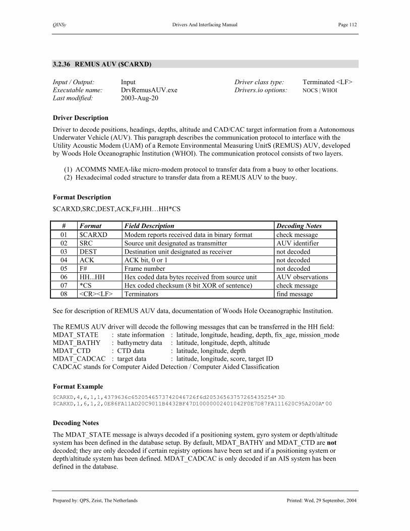
QINSy Drivers And Interfacing Manual Page 112
Prepared by: QPS, Zeist, The Netherlands Printed: Wed, 29 September, 2004
3.2.36 REMUS AUV ($CARXD) Input / Output: Input Driver class type: Terminated <LF> Executable name: DrvRemusAUV.exe Drivers.io options: NOCS | WHOI Last modified: 2003-Aug-20
Driver Description
Driver to decode positions, headings, depths, altitude and CAD/CAC target information from a Autonomous Underwater Vehicle (AUV). This paragraph describes the communication protocol to interface with the Utility Acoustic Modem (UAM) of a Remote Environmental Measuring UnitS (REMUS) AUV, developed by Woods Hole Oceanographic Institution (WHOI). The communication protocol consists of two layers.
(1) ACOMMS NMEA-like micro-modem protocol to transfer data from a buoy to other locations. (2) Hexadecimal coded structure to transfer data from a REMUS AUV to the buoy.
Format Description
$CARXD,SRC,DEST,ACK,F#,HH…HH*CS
# Format Field Description Decoding Notes 01 $CARXD Modem reports received data in binary format check message 02 SRC Source unit designated as transmitter AUV identifier 03 DEST Destination unit designated as receiver not decoded 04 ACK ACK bit, 0 or 1 not decoded 05 F# Frame number not decoded 06 HH...HH Hex coded data bytes received from source unit AUV observations 07 *CS Hex coded checksum (8 bit XOR of sentence) check message 08 <CR><LF> Terminators find message
See for description of REMUS AUV data, documentation of Woods Hole Oceanographic Institution. The REMUS AUV driver will decode the following messages that can be transferred in the HH field: MDAT_STATE : state information : latitude, longitude, heading, depth, fix_age, mission_mode MDAT_BATHY : bathymetry data : latitude, longitude, depth, altitude MDAT_CTD : CTD data : latitude, longitude, depth MDAT_CADCAC : target data : latitude, longitude, score, target ID CADCAC stands for Computer Aided Detection / Computer Aided Classification
Format Example $CARXD,4,6,1,1,4379636c6520546573742046726f6d20536563757265435254*3D $CARXD,1,6,1,2,0E86FA11AD20C9011B4432BF47D10000002401042F0E7D87FA111620C95A200A*00
Decoding Notes
The MDAT_STATE message is always decoded if a positioning system, gyro system or depth/altitude system has been defined in the database setup. By default, MDAT_BATHY and MDAT_CTD are not decoded; they are only decoded if certain registry options have been set and if a positioning system or depth/altitude system has been defined. MDAT_CADCAC is only decoded if an AIS system has been defined in the database.

QINSy Drivers And Interfacing Manual Page 113
Prepared by: QPS, Zeist, The Netherlands Printed: Wed, 29 September, 2004
The time information contained in the MDAT_STATE is currently not used by the REMUS AUV driver, because QPS hasn’t got enough information to be able to assess its usability. The other messages have no time field. Positions and other observations are now time-tagged at the moment they arrive at the COM port. Operation Mode. The position mode (solution mode) of a position contains the vehicles operation mode from the MDAT_STATE messages. Its value can be monitored in a Positioning System Display or it can be used to set a raw data alert in a Alert Display. Normal mission operation has got a value 6, but value 7 has also been encountered. Note. In QINSy versions prior to 2004.02.25 these were decoded as 12 and 14. Battery Percentage. The quality field of a heading, depth or altitude observation contains the percentage of the battery capacity that remains from the MDAT_STATE messages. It can be monitored in an Observation Physics Display or Alpha Numerical Display, or it can be used to set a raw data alert in a Alert Display. CAD/CAC Targets. Each MDAT_CADCAC message contains three sets of detected targets. The name of a detected target will be “CADCAC [n]”, where ‘n’ is the source unit that detected the target. Each detection will have 3 scores representing the results of 3 different processing algorithms. A perfect score is 100%. The average score is saved as AIS call sign and the 3 individual scores are saved as AIS destination, so that they can be made visible in a Navigation Display. The three detected targets are saved as observations in the raw database (if recording is on) and exported to a line database as points, for example target ‘i’ from AUV ‘n’:
Name Radius1 Attribute1 Comment CADCAC [n] i 100 – (average score) average score score 1, score 2, score 3; average; lat; lon
Note. The radius is an indication of the average score; the smaller the radius, the better the confidence.
Drivers.io Options
Drivers.io command line parameter “NOCS” disregards the checksum field. Omitting this parameter or using parameter “CS” will not decode the data when the checksum calculation fails. Parameter “WHOI” will set the format to the one described in this paragraph, but this is the only format the current driver supports.
Registry Options [HKEY_CURRENT_USER\Software\QPS\QINSy\7.0\Drivers\WHOI\Settings]
Registry Key Default Values Description Decode Bathy -1 -1, 0, 1, 2 Disregard MDAT_BATHY (-1) or decode Nth position Decode CTD -1 -1, 0, 1 Disregard MDAT_CTD (-1) or decode Nth position
Note. The position index to decode is zero-based, so enter 0 for first data set, 1 for the second one, etcetera. Communication with REMUS AUV’s through a buoy can be very slow, only a couple of MDAT_STATE messages per minute, so it is advisable to also use positions from the MDAT_BATHY and MDAT_CTD messages. According to WHOI personnel, these positions are valid as well. Apparently, the last data set in the messages is the most recent one, so use 2 for registry key “Decode Bathy” and 1 for “Decode CTD”. (continued on next page)

QINSy Drivers And Interfacing Manual Page 114
Prepared by: QPS, Zeist, The Netherlands Printed: Wed, 29 September, 2004
Database Setup
See description under “POSITION NAVIGATION SYSTEM DRIVERS”. In order to use multiple AUV positions, add a new “Object” for each AUV and add a “System” of type “Position navigation system” to each of the objects. Be sure to select the same driver and I/O parameters. Enter the appropriate source unit as receiver number. Since depths can be with respect to mean sea level, make sure to select the appropriate vertical datum. In order to decode the headings, add a “System” of type “Gyro” to each object. Enter the source unit as gyro observation slot id. To decode depths and/or altitudes, add a “System” of type “Underwater Sensor” to each object and add a depth and/or an altitude observation. Use source unit as slot number. Note. Altitude values are only present in MDAT_BATHY messages. CAD/CAC targets. In order to decode the CAD/CAC messages, add a system of type “AIS system” to the database setup, with driver "REMUS AUV ($CARXD) CAD/CAC Targets", which will end up under “Auxiliary Systems”. All decoded CAD/CAC targets will be stored real-time to a line database called “CADCAC Detection.pro” in the line data folder of the current project. The targets can be monitored in an Observation Physics Display and will pop up in a Navigation Display, if the proper settings have been set.
Online Setup
CAD/CAC targets. In order to monitor the decoded CAD/CAC targets in an Observation Physics Display, select the AIS system name. The name of an AIS target is displayed as “type (id) name”, so for example the first detection with target ID 3 from a CADCAC message will be displayed as “mine (3001) CADCAC [n]”. CAD/CAC targets. Decoded targets can be shown on a Navigation Display in two manners. (1) “Layers – Line Database ...”. Add the “CADCAC Detection.pro” from the current project. The detected targets will be shown as points, with the radius indicating the average score. (2) “Layers – AIS Targets ...”. Show targets including information or not. Newly detected targets will be visible for 30 seconds (registry setting).
Offline Options
CAD/CAC targets. If CAD/CAC targets have been saved to a storage database, the export option in the Raw Data Manager (“Replay” button in the QINSy Console) can be used to export them to a line database file. If CAD/CAC targets have been saved to a line database (i.e. “CADCAC Detection.pro” in the line data folder of the current project), they can be shown, edited and deleted using the Line Data Manager. Select “Edit Points” to get the list of targets. Hovering over a target will pop up a window showing scores and position.

QINSy Drivers And Interfacing Manual Page 115
Prepared by: QPS, Zeist, The Netherlands Printed: Wed, 29 September, 2004
3.2.37 RWSLod (0 Message)
3.2.38 Sercel Axyle (0 Message) No PPS Input / Output: Input Driver class type: Terminated <LF> Executable name: DrvRWSLod.exe Drivers.io options: none Last modified: 2000-Jan-27
Driver Description
Driver for RWSLod 0 message. Driver to be used to decode strings containing RD Easting, Northing, and height and quality information from external satellite receiver. The driver converts the RD coordinates to latitude and longitude.
Format Description
Each message has a variable length. A text label that designates the start of the particular item proceedes each item in the message. All fields are separated by spaces.
Field Format Description Values, Range, Units 1 <SPC><SPC><SPC>0 Message Identifier Always 3 spaces and 0 2 Hh:mm:ss.sss Time 00:00:00.000 – 23:59:59.999 3 Y=12345678.12 RD Northing Meters 4 X=12345678.12 RD Easting Meters 5 H=12345678.12 RD Height (above NAP) Meters 6 S=123.12 Speed 7 C=1234 Heading 8 Q=1 Quality indicator Stored in calculation mode field 9 N=12 Number of used satellites Stored
Format Example 0 6:48:13.200 Y= 501949.87 X= 157248.87 H= 8.46 S= 0.02 C= 0 Q=8 N= 8 <CR><LF> 0 6:48:13.800 Y= 501949.88 X= 157248.87 H= 8.46 S= 0.02 C= 0 Q=8 N= 8 <CR><LF>
Decoding Notes
The driver does not decode fields 6 and 7. The RD position is converted to a geographical position using the survey projection and selected datum. Time is only used when PPS is active or when USETIME option (Axyle) is active. The Height field (field 5) is optional and can be omitted in the output string. QINSy will assume height to be zero in that case.
System Configuration
The datum selected for this positioning system should always be identical to Survey Datum and the projection should be identical to the projection as programmed inside the (GPS) receiver. When used in the Netherlands this should be Bessel and RD.

QINSy Drivers And Interfacing Manual Page 116
Prepared by: QPS, Zeist, The Netherlands Printed: Wed, 29 September, 2004
Interfacing Notes
No specific interfacing or configuring recommendations. See Chapter 1 for general interfacing remarks.
Drivers.io Options
USETIME: When this option is used the time that was decoded from the message is always used as the observation time regardless the fact that QINSy works without PPS. In normal operation the absence of PPS would force the usage of the message arrival time being used as the observation time. This behaviour is overruled with the USETIME option. This option was implemented for usage with a, QINSy time synchronised, Sercel Axyle AP1 receiver.
Interfacing Notes
No specific interfacing or configuring recommendations. See Chapter 1 for general interfacing remarks.
Database Setup
See description under “POSITION NAVIGATION SYSTEM DRIVERS”.

QINSy Drivers And Interfacing Manual Page 117
Prepared by: QPS, Zeist, The Netherlands Printed: Wed, 29 September, 2004
3.2.39 Seatex Integrated GPS / GLONASS (NMEA GNS Format)
Input / Output: Input Driver class type: Terminated <LF> Executable name: DrvSeatexNMEAGNS.exe Drivers.io options: none Last modified: 1998-Nov-18
Driver Description
Driver for NMEA-0183 $--GNS sentences, containing integrated GPS / GLONASS position solution.
Format Description
Each $GPRMC sentence is variable in length, depending on the number of digits for the decimal fractions. Refer to NMEA 0183- Standard For Interfacing Electronic Devices - Version 2.30 for more information.
# Format Description Values, Range, Units 01 “$” start character “$” (24 Hex) 02 --GNS address field “--GNS” 03 “,” field delimiter “,” (2C Hex) 04 Hhmmss.ss UTC of position (hours,minutes,seconds) 0…23, 0…59, 0.00…59.99 05 “,” field delimiter “,” (2C Hex) 06 Llll.llllll latitude (degrees, minutes) 0…90, 0.00…59.999999, degrees 2
digits, minutes 4 digits. 07 “,” field delimiter “,” (2C Hex) 08 A latitude (northern or southern) “N” or “S” 09 “,” field delimiter “,” (2C Hex) 10 Yyyyy.yyyyyy longitude (degrees, minutes) 0…180, 0.00…59.999999, degrees 3
digits, minutes 4 digits. 11 “,” field delimiter “,” (2C Hex) 12 A longitude (eastern or western) “E” or “W” 13 “,” field delimiter “,” (2C Hex) 14 c--c mode indicator see table below 15 “,” field delimiter “,” (2C Hex) 16 Xx numbers of satellites 00…99 17 “,” field delimiter “,” (2C Hex) 18 x.x horizontal dilution of precision 19 “,” field delimiter “,” (2C Hex) 20 x.x antenna altitude above MSL meters 21 “,” field delimiter “,” (2C Hex) 22 x.x age of differential data 23 “,” field delimiter “,” (2C Hex) 24 Xxxx differential reference station ID 25 “*” checksum field delimiter “*” (2A Hex) 26 Hh checksum (XOR from “$” to “*” exclusive) 27 <CR><LF> termination characters <CR><LF> (0D Hex, 0A Hex)
Database Setup
See description under “POSITION NAVIGATION SYSTEM DRIVERS”.

QINSy Drivers And Interfacing Manual Page 118
Prepared by: QPS, Zeist, The Netherlands Printed: Wed, 29 September, 2004
3.2.40 Sercel 103 NMEA Position (ZDA & GLL)
Input / Output: Input Driver class type: Terminated <LF> Executable name: DrvNR103NMEA.exe Drivers.io options: format Last modified: 1997-May-01
Driver Description
Driver for Sercel NR103 and NR203 ZDA and GLL sentences, containing UTC and geographic position (latitude, longitude, height).
Format Description
This format is not a standard NMEA 183 format. The ZDA string contains the time and date of the fix, and the GLL string contains the latitude, longitude and height. An example of the combined data string is: Note. Be sure that the time field in the ZDA string is configured to output hundreds of seconds, because QPS personnel has seen that a Sercel receiver can truncate the number of seconds, not round it properly.
# Format Description Values, Range, Units 01 ZDA Message type identifier “ZDA” 02 “,” field delimiter “,” (2C Hex) 03 hhmmss.ss UTC time: hour, minutes and seconds 0..24, 0..60, 0.0..59.9 04 “,” field delimiter “,” (2C Hex) 05 dd,mm,yyyy Utc date: day month year 1..31, 1..12, 0000..9999 06 <CR><LF> termination characters <CR><LF> (0D Hex, 0A Hex) # Format Description Values, Range, Units 01 GLL Message type identifier “GLL” 02 “,” field delimiter “,” (2C Hex) 03 ddmm.mmmm Latitude (degrees, minutes) 0…90, 0.00…59.999999 04 “,” field delimiter “,” (2C Hex) 05 N latitude hemisphere “N” or “S” 06 “,” field delimiter “,” (2C Hex) 07 dddmm.mmmm Longitude (degrees, minutes) 0…180, 0.00…59.999999 08 “,” field delimiter “,” (2C Hex) 09 E longitude hemisphere “E” or “W” 10 “,” field delimiter “,” (2C Hex) 11 xx.xx altitude above MSL Meters if next field is “M” 12 “,” field delimiter “,” (2C Hex) 13 “M” height unit “M” for meters 14 <CR><LF> termination characters <CR><LF> (0D Hex, 0A Hex)
Format Example $ ZDA,175949.99,17,11,1998,12.0 GLL,5148.391484,N,528.023770,E,52.73,M
Database Setup
See description under “POSITION NAVIGATION SYSTEM DRIVERS”.

QINSy Drivers And Interfacing Manual Page 119
Prepared by: QPS, Zeist, The Netherlands Printed: Wed, 29 September, 2004
3.2.41 Sercel 103 NMEA Position ($GPGGA)
Input / Output: Input Driver class type: Terminated <LF> Executable name: DrvNR103NMEA.exe Drivers.io options: format Last modified: 1997-May-01
Driver Description
Driver for Sercel NR103 and NR203 $GPGGA sentence, containing UTC time, geographic position (latitude, longitude, height), and quality numbers (quality of the solution, number of satellites and HDOP). Driver can also be used together with $PSER,ATT or $A attitude strings from Sercel NR230 attitude sensor.
Format Description
Note. Be sure that the time field in the GGA string is configured to output hundreds of seconds, because QPS personnel has seen that a Sercel receiver can truncate the number of seconds, not round it properly.
# Format Description Values, Range, Units 01 $GPGGA Message type identifier “GGA” 02 “,” field delimiter “,” (2C Hex) 03 hhmmss.ss UTC time: hour, minutes and seconds 0..24, 0..60, 0.0..59.99 04 “,” field delimiter “,” (2C Hex) 03 ddmm.mmmm Latitude (degrees, minutes) 0…90, 0.00…59.999999 04 “,” field delimiter “,” (2C Hex) 05 N latitude hemisphere “N” or “S” 06 “,” field delimiter “,” (2C Hex) 07 dddmm.mmmm Longitude (degrees, minutes) 0…180, 0.00…59.999999 08 “,” field delimiter “,” (2C Hex) 09 E longitude hemisphere “E” or “W” 10 “,” field delimiter “,” (2C Hex) 11 x Fix quality Sercel Quality indicator 12 “,” field delimiter “,” (2C Hex) 13 x number of satellites used 14 “,” field delimiter “,” (2C Hex) 15 xxx HDOP unitless 16 “,” field delimiter “,” (2C Hex) 17 xx.xx altitude above MSL Meters if next field is “M” 18 “,” field delimiter “,” (2C Hex) 19 “M” height unit “M” for meters 20 xx.xx altitude of MSL above geoid Meters if next field is “M” 21 “,” field delimiter “,” (2C Hex) 22 “M” height unit “M” for meters 23 <CR><LF> termination characters <CR><LF> (0D Hex, 0A Hex)
Format Example $GPGGA,172452.99,5224.337,N,00452.979,E,9,8,1,35,M,82,M (continued on next page)

QINSy Drivers And Interfacing Manual Page 120
Prepared by: QPS, Zeist, The Netherlands Printed: Wed, 29 September, 2004
Interfacing Notes
No specific interfacing or configuring recommendations. See Chapter 1 for general interfacing remarks.
Database Setup
See description under “POSITION NAVIGATION SYSTEM DRIVERS”. Driver can also be used together with $PSER,ATT or $A attitude strings from Sercel NR230 attitude sensor.

QINSy Drivers And Interfacing Manual Page 121
Prepared by: QPS, Zeist, The Netherlands Printed: Wed, 29 September, 2004
3.2.42 Sercel Aquarius RTK (GPGGA)
This driver has been renamed. See description for driver “Aquarius RTK (GPGGA or GPLRK)”

QINSy Drivers And Interfacing Manual Page 122
Prepared by: QPS, Zeist, The Netherlands Printed: Wed, 29 September, 2004
3.2.43 Shallow Water Range Format #2
Input / Output: Input Driver class type: Terminated <CRLF> Executable name: DrvShallowWaterRange.exe Drivers.io options: - Last modified: 2000-July-14
Driver Description
Driver for decoding data strings in the Shallow Water Range Format #2, containing X, Y, Z range co-ordinates of tracked vessel(s), vessel identification code and time associated with the position.
Format Description
Each message has a variable length. All fields are separated by spaces. Field Format Description Values, Range, Units 01 $SW Message type identifier “$SW” 02 “ “ Space delimiter <SPACE> 03 dd Vessel identification code 0-99 04 “ “ Space delimiter <SPACE> 05 xxxxxxx X range co-ordinate ±999999 in International Feet 06 “ “ Space delimiter <SPACE> 07 yyyyyyy Y range co-ordinate ±999999 in International Feet 08 “ “ Space delimiter <SPACE> 09 zzzzz Altitude or Depth co-ordinate
+z implies altitude above mean sea level -z implies depth below mean sea level
±9999 in International Feet
10 “ “ Space delimiter <SPACE> 11 yyddd Two digit year and day of the year associated with
the track point yy : 00-99 ddd : 001-366
12 “ “ Space delimiter <SPACE> 13 sssss.sss Seconds since midnight associated with the track
point 00000.000 – 86399.000
14 <CR><LF> Termination characters <CR><LF> (0D Hex, 0A Hex)
Format Example $SW 2 1234567 3456789 -12.4 00187 12345.678
Interfacing Notes
No specific interfacing or configuring recommendations. See Chapter 1 for general interfacing remarks.
Database Setup
See description under “POSITION NAVIGATION SYSTEM DRIVERS”. Add a “Variable Node” for the vessel/target node to the QINSy Database. Add a “Position navigation system” using the appropriate driver and interfacing parameters. Select the object, the tagret node and the receiver number. Be sure to enter the same number as the vessel identification code, which is present in the data string, for which the positions are to be decoded (used as slot number in QINSy).

QINSy Drivers And Interfacing Manual Page 123
Prepared by: QPS, Zeist, The Netherlands Printed: Wed, 29 September, 2004
3.2.44 Simrad HPR LBL (Position Output)
Input / Output: Input Driver class type: Terminated <LF> Executable name: DrvSimradLBLPosition.exe Drivers.io options: none Last modified: 1998-Nov-11
Driver Description
Driver to decode Simrad HPR 400 LBL position and depth in NMEA 0183 format.
Format Description
Refer to the “Standard for interfacing Marine Electronics Devices NMEA 0183 Version 2.20”. $PSIMLBP,hhmmss.ss,c—c,c—c,c—c,aa_,x.x,x.x,x.x,x.x,x.x,x.x,x.x*hh<CRLF>
# Field Name Explanation 1 $ Start character 2 PSIMLBP Address propr. Simrad address for LBL position. 3 ,hhmmss.ss Clock clock in hours, minutes, seconds (decimal fraction optional).4 ,c—c Tp array transponder array for which origin is valid. 5 ,c—c Type type of item positioned (vessel or ROV). 6 ,c—c Status status of position. ‘A’ is OK. 7 ,aa_ Coördinates see description below. 8 ,x.x X coördinate see description below. 9 ,x.x Y coördinate see description below. 10 ,x.x Depth depth of position. 11 ,x.x Major major axis of error ellipse. 12 ,x.x Minor minor axis of error ellipse. 13 ,x.x Direction direction of major axis in error ellipse. 14 ,x.x Res rms root mean square value of normalised residuals. 15 *hh Checksum empty or checksum. 16 CRLF Termination
Coordinate System
The cartesian coördinates are the position of the vessel or ROV in metres relative to the origin of the transponder array. The Eastings and Northings are the UTM coördinates of the vessel or ROV.
Coördinate Coördinate system X Coördinate Y Coördinate Cartesian N/E C North East Cartesian E/N L East North
UTM N/E U Northings Eastings UTM E/N E Eastings Northings
(continued on next page)

QINSy Drivers And Interfacing Manual Page 124
Prepared by: QPS, Zeist, The Netherlands Printed: Wed, 29 September, 2004
Decoding Notes
The driver only uses the UTM N/E or UTM E/N coordinates. Easting and Northing are converted to latitude and longitude. Depth is decoded as negative height. The RMS value is used for latitude/longitude/height SD. Use an “Alert Display” to setup an “Position RMS outside limit” raw data alert to test this RMS value.
Database Setup
See description under “POSITION NAVIGATION SYSTEM DRIVERS”. To decode the position, add a “Variable Node” for the Simrad LBL transducer to the QINSy Database. Add a “Position navigation system” and set the appropriate driver and interfacing parameters. Select the survey datum for the (satellite) system and select the LBL transducer node as receiver.

QINSy Drivers And Interfacing Manual Page 125
Prepared by: QPS, Zeist, The Netherlands Printed: Wed, 29 September, 2004
3.2.45 Sonardyne APS3 (Position Output)
Input / Output: Input Driver class type: Terminated <LF> Executable name: DrvSonardyneAPS3.exe Drivers.io options: N | DT x.x (age) Last modified: 1998-Jul-01
Driver Description
Driver to decode Sonardyne Acoustic Positioning System (APS3) position and/or heading in FXT format. Other APS3 output string formats, TRACV and NAVCO output strings, have not yet been implemented.
Format Description
Each APS3 FXT record is fixed in length, leading zeros must be included. Since QPS has encountered different variations of this format, the time field is not used (decoded) in the present QINSy driver.
# Format Description Values, Range, Units, Units 01 “FXT” start of data “FXT” 02 “;” field delimiter “;” 03 hh:mm:ss Time of position hours : minutes : seconds 04 “,” field delimiter “,” 05 Exxxxxx.xx Easting metres 06 “,” field delimiter “,” 07 Nxxxxxxx.xx Northing metres 08 “,” field delimiter “,” 09 Dxxxx.xx Depth metres 10 “,” field delimiter “,” 11 Axx.xx Position RMS metres 12 “,” field delimiter “,” 13 Hxxx.x Heading degrees 14 “,” field delimiter “,” 15 Tn Target number 1 to 5 in Multi-Track 16 <CR><LF> record termination CarriageReturn LineFeed
Format Example
Example string logged onboard vessel “Louis G Murray” (owned by De Beers Marine): FXT;00005.54,TARGET Vessel ,E793298.12,N6248948.10,D0010.00,A05.07,H000.0
Decoding Notes
Easting and Northing are converted to latitude and longitude. Depth is decoded as negative height. The RMS value is used for latitude/longitude/height SD. Heading is decoded if a true bearing observation is connected. Use an “Alert Display” to setup an “Position RMS outside limit” raw data alert to test the RMS value.
Database Setup
To decode the position, add a “Variable Node” for the Sonardyne APS3 transducer to the QINSy Database. Add a “Position navigation system” and set the appropriate driver and interfacing parameters. Select the survey datum for the (satellite) system and select the APS3 transducer node as receiver.

QINSy Drivers And Interfacing Manual Page 126
Prepared by: QPS, Zeist, The Netherlands Printed: Wed, 29 September, 2004
Database Setup (continued)
To decode the heading, add an “Observation” of type “Bearing, true”, add a “System” of type “Gyro”, select driver, and connect the heading observation. To decode all observations, add both system types to the QINSy database and make sure to select the same driver name and serial interfacing parameters for both systems.
Format Description (TRACV format is for future reference)
To select TRACV or NAVCO output format, the “NavCompOut=” line in the APS3 INI file has to be edited. Both strings have fixed length fields and so are not delimited. The TRACV output will place leading zeros in a field if the number is too small, whereas the NAVCO output will place leading spaces in front of a number. Example TRACV string logged onboard vessel “Louis G Murray” (owned by De Beers Marine): 111:14:21900793429.4406248881.2504.90010.0000:00:0000000.0000:00:000 MTT:TT:TTTEEEEEEEE.EENNNNNNNN.NNQQ.QHHHH.HHZZ:ZZ:ZZZYYYY.YYXX:XX:XXX 01234567890123456789012345678901234567890123456789012345678901234567
# Format Description Values, Range, Units, Units 01 M Mobile number 1 to 5 02 TT:TT:TTT Time of data hours : minutes : 0.1 seconds 03 EEEEEEEE.EE Easting (metres ?) 04 NNNNNNNN.NN Northing (metres ?) 05 QQ.Q RMS of data (metres ?) 06 HHHH.HH Precision depth metres of feet (unitsof Tcvr 1) 07 ZZ:ZZ:ZZZ Time of precision observation hours : minutes : 0.1 seconds 08 YYYY.YY Corrected depth of reference sensor (metres ?) 09 XX:XX:XXX Time of corrected depth observation hours : minutes : 0.1 seconds
Example NAVCO string logged onboard vessel “Louis G Murray” (owned by De Beers Marine): 11105227 12 79339147 624887613 1001 55$RSVHT 0.0 0.0 0.0 MMTTTTTTTAAAEEEEEEEEEENNNNNNNNNNHHHHHFQQQQ$RSVHTBBB.BDD.DGGG.G 01234567890123456789012345678901234567890123456789012345678901
# Format Description Values, Range, Units 01 MM Mobile number 1 to 5 02 TTTTTTT Time of data hours : minutes : 0.1 seconds 03 AAA Age of data 0.1 seconds 04 EEEEEEEEEE Easting 0.01 (metres ?) 05 NNNNNNNNNN Northing 0.01 (metres ?) 06 HHHHH Depth metres of feet (unitsof Tcvr 1) 07 F constant “1” 08 QQQQ RMS of data 0.1 (metres ?) 09 “$RSVHT” start of NMEA string “$RSVHT” 10 BBB.B Mobile bearing degrees 11 DD.D Dangle angle degrees 12 GGG.G Dangle bearing degrees
Note 1. Eastings, northings and depth and bearing are zero for sensor only targets. Note 2. Dangle angle and dangle bearing are zero for navigating targets.

QINSy Drivers And Interfacing Manual Page 127
Prepared by: QPS, Zeist, The Netherlands Printed: Wed, 29 September, 2004
3.2.46 Sonardyne LUSBL (LBL / USBL, V5 / V6) Input / Output: Input (two-way) Driver class type: Terminated <LF> Executable name: DrvSonardyneLUSBL.exe Drivers.io options: V5 | V6 Last modified: 1999-Oct-21
Driver Description
This driver will decode LBL and USBL measurements from the Sonardyne LUSBL unit with firmware version 5 and version 6. In version 5 only one LBL position can be decoded as well as multiple USBL measurements. In version 6 multiple LBL positions and USBL measaurements can be decoded.
Format Description
The output format depends on the initialization string send to the LUSBL computer on startup, or when resetting the I/O in QINSy. The following strings are sent: Version 5: LBL:select,1,\rselect,2,filt_e,filt_n,filt_d\r USBL: select,2,\rselect,1,index,filt_e,filt_n,filt_d\r Version 6: Initialization: select,1,\rselect,2,\r LBL:select,2,name,east,north,depth,h_ell_drn,h_ell_maj,h_ell_min,z_err\r USBL:select,1,name,index,east,north,depth,quality\r
Decoding Notes
As the LUSBL system outputs in meters, the driver will convert it to the survey units used in QINSy. For version 6 in LBL mode the z_err value will be set as the sd of the depth in QINSy. In USBL mode the quality value will be set to the quality indicator value in QINSy.
System Configuration
In version 5 it is not possible to output LBL data and USBL data on one port. In version 6 it is possible to output multiple LBL positions and USBL measurements on one port. In DB Setup you can then define the LBL systems and USBL system on the same port.
Interfacing Notes
Type of cable wiring (two-way). Cable wiring diagrams:
DB-25 Sensor DB-9 COM DB-25 COM Pin 2 RXD ----------------- Pin 3 TXD Pin 2 TXD Pin 3 TXD ----------------- Pin 2 RXD Pin 3 RXD Pin 7 SG ----------------- Pin 5 SG Pin 7 SG

QINSy Drivers And Interfacing Manual Page 128
Prepared by: QPS, Zeist, The Netherlands Printed: Wed, 29 September, 2004
Database Setup
LBL Setup: First define and select the “Object” on which the LBL transponder is located. Select item “Systems” and defined a new “Position navigation system”. Select the Sonardyne LUSBL LBL driver and interface parameters. Press the “Next” button to complete the setup. Select object and node for the transponder. Press the “Finish” button to save the system.
A new transponder node can be added by pressing the button; to change its properties, press the button. For every transponder on the object a new system must be defined (with the same driver and eventually on the same COM port). To identify the transponder the system name must be the same as the transponder name (e.g. CRAWLER or RANGEMASTER). The receiver ID must be a unique number (0 – 999). USBL Setup: To decode the X, Y and Z observations, add a variable node for the USBL transponder. Add a “System” of type “USBL Sensor”, and select the Sonardyne LUSBL USBL driver. There is no need to define the three observations separately, since they are automatically added and connected to the system. Change Parameters and Corrections to match the sign conventions and corrections for this system. See the ”Clarifications of rotation” that are part of the module’s Help, for a better understanding of how to use the conventions.
A new transponder node can be added by pressing the button; to change its properties, press the button. Connect the variable USBL node on the Targets tabsheet and enter the correct Slot Id. The Slot Id depends on the used transponder/responder. In version 5 the driver will decode the USBL transponder index. In version 6 the driver will decode the name of the transponder (e.g 305 or MINIROVNAV (max 10 characters)).
Drivers.io Options
“V5” will decode output from version 5 firmware. “V6” will decode output from version 6 firmware.

QINSy Drivers And Interfacing Manual Page 129
Prepared by: QPS, Zeist, The Netherlands Printed: Wed, 29 September, 2004
3.2.47 Subsea Telemetry Format
Input / Output: Input Driver class type: Terminated <LF> Executable name: DrvSubseaTelemetry.exe Drivers.io options: NOCS Last modified: 2000-April-19
Driver Description
Driver to decode position or heading data which originates from the Subsea telemetry system. Data may hold multiple positions. Encoding is handled as described in 3.18.51 The format followed for the transfer of data in/out using the SubSea Telemetry option is based upon the NMEA 0183 message formats for heading and position. The NMEA 0183 documentation detailing the standard GGA and HDT messages is appended. Note that there are several points where the actual message form varies from the standard : • The address fields have been altered to reflect the code of the vessel originating the data. The result is
that $GPGGA is altered to $Gc where c is the code (0-10)of the originating vessel, and $HEHDT is altered to $Hc.
• If the heading and the position are output simultaneously, the <cr><lf> is removed from the end of the $Gc string (leaving the *hh) and the $Hc string is appended to the end with its *hh<cr><lf> left intact.
• In the output, if any fields are unknown, eg Geoid separation, they are set to 0. • The GPS status is interpreted as defined by Sercel (for the NR103/NR203 receivers), not as detailed in
the NMEA 0183 document. Note that the latitude and longitude must be in WGS84.
Format Description
SUBSEA TELEMETRY FORMAT: $G1,152055.00,5659.6671,N,00201.1311,W,99,00,0.0,0.0,M,,,00,0000*32$H1,355,T*1E $G2,152054.00,5659.6645,N,00201.2174,W,99,00,0.0,0.0,M,,,00,0000*35$H2,000,T*1E $G3,152054.00,5659.6524,N,00201.1114,W,99,00,0.0,0.0,M,,,00,0000*35$H3,000,T*1F
# Format Description Values, Range, Units 01 $Gn Identifier where n is vessel Id n = 0 – …. 02 ,hhmmss.ss Time 03 ,ddmm.mmm Latitude (WGS-84) 04 ,N Hemisphere N or S 03 ,ddd,mm.mmmm Longitude (WGS-84) 04 ,E Hemisphere E or W 05 ,99 Ignored 06 ,00 Ignored 07 ,0.0 Ignored 08 ,a.a,M Altitude above MSL Positive sign = up 09 *hh Checksum Checksum 10 $Hn Identifier where n is vessel Id n = 0 – 9 11 ,ddd,T True heading Degrees 12 *hh Checksum Checksum 12 <cr><lf> Carriage Return Line Feed

QINSy Drivers And Interfacing Manual Page 130
Prepared by: QPS, Zeist, The Netherlands Printed: Wed, 29 September, 2004
Decoding Notes
Heading is only decoded if a Subsea Telemetry (Heading) driver is defined.
Interfacing Notes
No specific interfacing or configuring recommendations. See Chapter 1 for general interfacing remarks. (continued on next page)
Database Setup
See description under “POSITION NAVIGATION SYSTEM DRIVERS”. The Subsea Telemetry driver can be used to obtain a position and/or a gyro reading. Select a different system with its own type for each one of the data types to be decoded. Be sure to define the same interfacing parameters, including driver description and COM port number and settings, for all of these systems. To use the position, add a “Variable Node” for the antenna to the QINSy Database. Add a “System” of type “Position navigation system” and define the interfacing parameters. Select the satellite system and its datum. Select receiver position and enter receiver number. This number is used as a slot number to decode the correct positon from the data message. To use the gyro reading, add a “Variable Node” for the (gyro)compass to the QINSy Database (if it differs from the object’s reference point). Add a “Observation” of type “Bearing, magnetic” or “Bearing, true” and select the appropriate unit. Select the (gyro)compass node as “At node” and the “Null node” as “To node”. Add a new “System” of type “Gyro or compass” and define the I/O parameters. Connect the observation. Enter the slot number corresponding to the heading you wich to decode from the data message. Choose the No checksum option to disable the checksum check.

QINSy Drivers And Interfacing Manual Page 131
Prepared by: QPS, Zeist, The Netherlands Printed: Wed, 29 September, 2004
3.2.48 Syledis SR3 Position (Position | Heading | Speed) Input / Output: Input Driver class type: Terminated <CF> Executable name: DrvSyledisSR3Pos.exe Drivers.io options none Last modified: 1999-Oct-29
Driver Description
Driver for Syledis SR3 messages. Driver is able of decoding position in Northing / Easting format. Besides, this driver can be used to decode heading in degrees (no decimals) or speed in knots (one decimal).
Format Description
Item Description Start of text <SPACE> Timestamp 300H101138 Day = 300 Time = 10:11:38 Space <SPACE> Northing in meters Y+0385922.2 (1 decimal accuracy) Space <SPACE> Easting in meters X+0059403.5 (1 decimal accuracy) Space <SPACE> Heading and speed 013V0011 H = 013 degrees V = 1.1 knots Space <SPACE> Quality Q1011028 Filtering strictness = 1 DRMS = 11 m LPME = 28 m Carriage Return <CR> Line Feed <LF> • DRMS = Deviation Root Mean Square (in meters), LPME = Line Position Mean Error (in meters); • Gyro value (if decoded) is in degrees, has no decimals and is most likely COG; • Speed value (if decoded) is in knots, has one decimal and is most likely SOG; • Height value is not supplied and considered to be 0 (for computation.exe); • Timetag is ignored as it is unclear how its relation is to UTC; • Depending on the flag set in drivers.io either DRMS, LPME or the filter quality flag is copied to the
positioning data as quality indicator. Default behaviour is DRMS as the quality indicator.
Format Example
Example of Syledis SR3-strings logged onboard vessel “Arne” (owned by Rijkswaterstaat): 300H101138 Y+0385922.2 X+0059403.5 013V0011 Q1011028<CF><LF>
Decoding Notes
At the moment Latitude / Longitude format, which can be selected via the Syledis SR3 computer, is not supported meaning that only Northing / Easting format can be decoded well. Easting and Northing are converted to latitude and longitude using defined projection and selected system datum parameters.
Database Setup
See description under “POSITION NAVIGATION SYSTEM DRIVERS”.

QINSy Drivers And Interfacing Manual Page 132
Prepared by: QPS, Zeist, The Netherlands Printed: Wed, 29 September, 2004
3.2.49 Trimble 4000 (ASCII Printout)
3.2.50 Trimble 4000 (ASCII Printout) DGPS Check
3.2.51 Trimble 4000 (ASCII Printout) RTK Check
Input / Output: Input Driver class type: Terminated 0x03 Executable name: DrvTrimbleASCII.exe Drivers.io options: DGPS | RTK Last modified: 2003-Aug-20
Driver Description
Driver for the computed receiver position by a Trimble receiver in ASCII Cycle Printout format. In case of the “Trimble 4000 (ASCII Printout) DGPS Check” driver, only differential positions are accepted, i.e. positions with status ‘d’ (or ‘f’ or ‘i’). In case of the “Trimble 4000 (ASCII Printout) RTK Check” driver, only RTK fixed solutions are accepted, i.e. positions with status ‘i’. See for more information below.
Format Examples
Example data of CYCLE PRINTOUT data when differential corrections are lost: ID DAY DOY DATE TIME LATITUDE LONGITUDE HGT PDOP CLOCK V.VEL H.VEL HDG FREQ.OFFSET CONT S SVS [00 MON 227 14-AUG-00 14:59:23 26:52.6475N 050:26.5502E +0012 02.2 772643 -000.04 010.44 225.4 -1.0100E-07 2,20,19,8,1,27,13,31,3] Example of CYCLE PRINTOUT data with differential corrections: ID DAY DOY DATE TIME LATITUDE LONGITUDE HGT PDOP CLOCK V.VEL H.VEL HDG FREQ.OFFSET CONT S SVS [00 MON 227 14-AUG-00 14:46:43d26:54.1706N 050:28.3304E -0002 02.3 849159 +000.00 010.67 228.9 -1.0026E-07 20,19,8,1,27,13,31,3]
Decoding Notes
The GPS solution mode (that can occur at character position 31 in the modified Trimble ASCII Cycle Printout) is converted to a position mode (see Positioning System Display) and interpreted as follows:
char Solution Mode Position Mode No Check DGPS Check RTK Check ‘ ‘ autonomous solution 0 Decoded Not Decoded Not Decoded ‘d’ DGPS corrections OK 1 Decoded Decoded Not Decoded ‘f’ RTK float solution 2 Decoded Decoded Not Decoded ‘i’ RTK fixed solution 3 Decoded Decoded Decoded ?? unsupported mode 9 Decoded Decoded Decoded
Database Setup
See description under “POSITION NAVIGATION SYSTEM DRIVERS”.

QINSy Drivers And Interfacing Manual Page 133
Prepared by: QPS, Zeist, The Netherlands Printed: Wed, 29 September, 2004
3.2.52 Trimble TSIP Position Input / Output: Input (two-way) Driver class type: Terminated 0x03 Executable name: DrvTrimbleSIP.exe Drivers.io options: none Last modified: 1999-Sep-15
Driver Description
Driver for the computed receiver position in TSIP format. The QINSy driver will configure the receiver.
Format Description
The data is binary and wrapped in a standard TSIP wrapper. The data byte format for this report 0x84 is:
# Bytes Description Values, Range, Units 1 [0,7] Latitude radians, + for north 2 [8,15] Longitude radians, + for east 3 [16,23 Altitude meters above ellipsoid 4 [24,31] Clock bias meters 5 [32,35] Time of fix GPS seconds of the week
Note: The driver sets the altitude to the height above the ellipsoid, the tme of fix is set to GPS time.
Database Setup
See description under “POSITION NAVIGATION SYSTEM DRIVERS”.

QINSy Drivers And Interfacing Manual Page 134
Prepared by: QPS, Zeist, The Netherlands Printed: Wed, 29 September, 2004
3.2.53 UDI-NAV Header (Heading | Position)
Input / Output: Input Driver class type: Terminated <LF> Executable name: DrvHdrUDINav.exe Drivers.io options: none Last modified: 1999-May-31
Driver Description
Driver for old and new UDI header telegrams. Driver is able of decoding grid position as well as grid heading from three different telegrams as found in the UDI software. The following formats are supported: UDI Nav Header; Fugro UDI Surface Position Telegram; Fugro UDI Acoustic Position Telegram.
Format Description
UDI NAV HEADER: ????FFFtttttttttttttttttttEEEEEEEEEENNNNNNNNNNeeeeeeeeeennnnnnnnnnGGGGGKKKKKKKK<CR><LF>
# Format Description Values, Range, Units 01 ???? Unknown Ignored 02 FFF Fix number Ignored 03 Ttttttttttttttttttt Julian day in seconds Ignored 04 EEEEEEEEEE Easting Grid easting 03 NNNNNNNNNN Northing Grid Northing 04 EEEEEEEEEE Secondary easting Grid easting 05 NNNNNNNNNN Secondary northing Grid northing 06 GGGGG Vessel heading (grid) Converted by driver to true heading 07 KKKKKKKK Vessel Kp Ignored 08 <CR> Carriage Return 0x0D 09 <LF> Line Feed 0x0A
Decoding Notes
Easting and Northing are converted to latitude and longitude using defined projection and selected system datum parameters. Heading is only decoded if a UDI Nav Header Heading driver is defined.
Format Description (continued)
SURFACE POSITION TELEGRAM: XXyyy12301:01:01.001 Apr 19840501234.886781234.650501266.436782134.73004.2 23.873 -12<CR><LF>X
Note: When radio systems are used the data radio control bytes may or may not be stripped by the radios.
# Format Description Values, Range, Units 01 XX Data radio control 0xC0, 0x00 02 Yyy Header 0xCF, 0xE4, 0xDD 03 Zzz Code > 100 and < 200 for surface position 04 Hh:mm:ss.s Time Ignored 03 Dd mmm yyyy Date Ignored 04 Xxxxxxx.xx Vessel reference point Easting Grid easting 05 Xxxxxxx.xx Vessel reference point Northing Grid northing

QINSy Drivers And Interfacing Manual Page 135
Prepared by: QPS, Zeist, The Netherlands Printed: Wed, 29 September, 2004
06 Xxxxxxx.xx Vessel measure point Easting Grid easting 07 Xxxxxxx.xx Vessel measure point Northing Grid northing 08 Xxx.x Standard deviation prime system Ignored 09 Xxx.x Vessel heading (grid) Converted by driver to true heading 10 Xxx.x Speed made good Ignored 11 Xxxx.xxx Vessel Kp Ignored 12 Xxxxxx Distance offtrack Ignored 13 <CR> Carriage Return 0x0D 14 <LF> Line Feed 0x0A 15 X Data radio control 0xC0
Decoding Notes
Easting and Northing are converted to latitude and longitude using defined projection and selected system datum parameters. Heading is only decoded if a UDI Nav Header Heading driver is defined.
Format Description (continued)
ACOUSTIC POSITION TELEGRAM: XXyyy12301:01:01.001 Apr 1984123451234567.891234567.89123.411234.5123451234.567<CR><LF>X Note: When radio systems are used the data radio control bytes may or may not be stripped by the radios.
# Format Description Values, Range, Units 01 XX Data radio control 0xC0, 0x00 02 Yyy Header 0xCF, 0xE4, 0xDD 03 Zzz Code > 200 and < 300 for acoustic position 04 Hh:mm:ss.s Time Ignored 03 Dd mmm yyyy Date Ignored 04 Xxxxx Transponder address Ignored 05 Xxxxxxx.xx Acoustic measure point Easting Grid easting 06 Xxxxxxx.xx Acoustic measure point Northing Grid northing 08 Xxx.x Standard deviation acoustic fix Ignored 09 X Number of ranges used in fix Ignored 10 Xxxx.x Depth transponder Reversed by driver to height 11 Xxxxx Fix number Ignored 12 Xxxx.xxx Kp acoustic fix Ignored 13 <CR> Carriage Return 0x0D 14 <LF> Line Feed 0x0A 15 X Data radio control 0xC0
Decoding Notes
Easting and Northing are converted to latitude and longitude using defined projection and selected system datum parameters. Depth is decoded as negative height.
Interfacing Notes
No specific interfacing or configuring recommendations. See Chapter 1 for general interfacing remarks. (continued on next page)

QINSy Drivers And Interfacing Manual Page 136
Prepared by: QPS, Zeist, The Netherlands Printed: Wed, 29 September, 2004
Database Setup
See description under “POSITION NAVIGATION SYSTEM DRIVERS”. The UDI-NAV header can be used to obtain a position and/or a gyro reading. Select a different system with its own type for each one of the data types to be decoded. Be sure to define the same interfacing parameters, including driver description and COM port number and settings, for all of these systems. To use the position, add a “Variable Node” for the antenna to the QINSy Database. Add a “System” of type “Position navigation system” and define the interfacing parameters. Select the satellite system and its datum. Select receiver position and enter receiver number. The latter is not required, it is not used in this driver. To use the gyro reading, add a “Variable Node” for the (gyro)compass to the QINSy Database (if it differs from the object’s reference point). Add a “Observation” of type “Bearing, magnetic” or “Bearing, true” and select the appropriate unit. Select the (gyro)compass node as “At node” and the “Null node” as “To node”. Add a new “System” of type “Gyro or compass” and define the I/O parameters. Connect the observation.

QINSy Drivers And Interfacing Manual Page 137
Prepared by: QPS, Zeist, The Netherlands Printed: Wed, 29 September, 2004
3.2.54 WinSocket NMEA Position (GPGGA)
Input / Output: Input (TCP/IP) Driver class type: TCP/IP Client Executable name: DrvNMEASocket.exe Drivers.io options: N | ELL | MSL | NOCS Last modified: 2004-Aug-03
Driver Description
Driver to decode NMEA ‘$GPGGA’ sentences (or ‘$PTNL,GGK’ sentences) from a TCP/IP network connection. Driver does not handle NMEA sentences from UDP/IP connections, see remarks below.
Format Description
See for the $--GGA (or $--GGK) sentence descriptions the various NMEA positioning system driver format descriptions elsewhere. See NMEA 0183- Standard For Interfacing Electronic Devices - Version 2.30.
Decoding Notes
If PPS is connected, then the time field from the input data string is used. Otherwise, the timetag will be set when the last byte of the NMEA sentence is recieved. Since data transfer over TCP/IP network connections can vary considerably, there is no correction for string length and latency applied. Therefore, only use this driver when PPS is connected, or when exact timing of positions is not an issue.
Drivers.io Options
Command line parameter ‘N’ indicates the type of NMEA sentence that will be decoded. Currently only ‘1’ (GPGGA) and ‘1024’ (GGK, e.g. Trimble TNL) are supported. The ‘NOCS’ parameter will make the driver ignore the checksum field. ’MSL’ gets the altitude from the message and adds the geoidal separation before storing it. ‘ELL’ will only decode the altitude field and store it as height on the ellipsoid.
Online Setup
The NMEA WinSocket driver only supports TCP/IP network connections, not UDP/IP communications. TCP/IP (Transmission Control Protocol / Internet Protocol) is based on a connection between 2 computers. UDP (User Datagram Protocol) is based on connectionless communication. The primary difference between TCP and UDP lies in their respective implementations of reliable messaging. TCP includes support for guaranteed delivery, meaning that the recipient automatically acknowledges the sender when a message is received, and the sender waits and retries in cases where the receiver does not respond in a timely way. UDP, on the other hand, does not implement guaranteed message delivery. A UDP datagram can get ‘lost’ on the way from sender to receiver, and the protocol itself does nothing to detect or report this condition. However, UDP messaging will be faster, since UDP packets are limited in size and no connection setup is required. TCP is used for normal Internet traffic and applications such as web servers and FTP, whereas UDP is ideal for applications like video streaming and online gaming, where speed takes precedence over lost packets.
Database Setup
See description under “POSITION NAVIGATION SYSTEM DRIVERS”. Enter port number and IP adress from the sending computer on the TCP/IP network.

QINSy Drivers And Interfacing Manual Page 138
Prepared by: QPS, Zeist, The Netherlands Printed: Wed, 29 September, 2004
(This page intentionally left blank)

QINSy Drivers And Interfacing Manual Page 139
Prepared by: QPS, Zeist, The Netherlands Printed: Wed, 29 September, 2004
3.3 GYRO’S AND COMPASSES SYSTEM DRIVERS
Database Setup
First define and select the “Object” on which the gyro or compass is located. Add a new system of type “Gyro’s and compasses” and select the appropriate driver and interface parameters. Press “Next” button to finish the setup. There is no need to define a true bearing observation, since it is automatically added to the system. Select the object for which the gyro observation is valid. Enter the observation parameters, such as unit and (C-O) value, and its slot number, if needed. Finally, press “Finish” button to save the system.

QINSy Drivers And Interfacing Manual Page 140
Prepared by: QPS, Zeist, The Netherlands Printed: Wed, 29 September, 2004
Database Setup (continued)
A new object can be added by pressing the button. Be aware that in this case it does not refer to a node.
See for more information the QINSy DB Setup Help Topics or the QINSy Knowledge Base.

QINSy Drivers And Interfacing Manual Page 141
Prepared by: QPS, Zeist, The Netherlands Printed: Wed, 29 September, 2004
3.3.1 Digilog (ASCII)
3.3.2 Digilog (Modified Anschutz)
Input / Output: Input Driver class type: Terminated Executable name: DrvGyroDigilog.exe Drivers.io options: format | OI Last modified: 2000-Jan-19
Driver Description
Driver for Digilog gyro compass output sentences, containing (gyro)compass heading, pitch and roll data. Driver can be used as gyro system, to obtain the heading, and as MRU system, to obtain the pitch and roll. Two formats can be decoded, the Digilog ASCII comms format and the Modified Anschutz format, matching the Anschutz telegram format with the addition of pitch and roll encoded in the magnetic heading locations. The ASCII SG Brown format output by a Digilog compass can be decoded using Sperry Repeater (ASCII). When option “OISTAR” has been selected, the driver will use timetags from preceding OiSTAR headers.
Format Description
Digilog ASCII comms format sentences are 20 bytes long, including termination characters <CR><LF>. HxxxxPsxxxxRsxxxxT<CR><LF>
# Format Description Values, Units 01 H heading flag “H” 02 xxxx decimal heading value 0.1 degrees 03 P pitch flag “P” 04 sxxxx decimal pitch angle value 0.1 degrees 05 R roll flag “R” 06 sxxxx decimal roll angle value 0.1 degrees 07 T status flag “E” exact heading available
“T” timeout “H” heating “S” settling “N” unvalid08 <CR><LF> termination characters <CR><LF> (0D Hex, 0A Hex)
Digilog Modified Anschutz sentences are 18 bytes long, including start (STX) and end (ETX) identifiers. STX<B1><B2><B3><B4><B5><B6><B7><B8><B9><B10><B11><B12><B13><B14><B15><B16>ETX
# Format Description Values, Units STX STX start identifier 02 Hex b1 01xxxxxx gyro reading 12 bits continued in <b2> b2 01xxxxxx gyro reading LSB = 0.0878906 degrees b3 01xxxxxx course changing clock frame pulse of 80 ms b4 01sxxxxx pitch value 12 bits; s = sign bit (0 = positive, 1 = negative) b5 01xxxxxx pitch value LSB = 0.0878906 degrees b6 01sxxxxx roll value 12 bits; s = sign bit (0 = positive, 1 = negative) b7 01xxxxxx roll value LSB = 0.0878906 degrees b8 01vxmxxx rate of turn 18 bits continued in <b9><b10> b9 01xxxxxx rate of turn v = sign bit (0 = positive, 1 = negative) b10 01xxxxxn rate of turn m = 2636.718 º/min, n = 0.08046 º/min

QINSy Drivers And Interfacing Manual Page 142
Prepared by: QPS, Zeist, The Netherlands Printed: Wed, 29 September, 2004
# Format Description Values, Units
b11 01abcdef status 12 bits continued in <b12> b12 01ghijkl status f g indicate data status flags b13 01nnnnnn compass data 18 bits continued in <b14><b15> b14 01xxxxxx compass data see Digilog gyro compass user manual b15 01xxxxxx compass data for desciption of compass data fields b16 01xxxxxx checksum FF EOR b1 to b5 AND 00111111 OR 01000000 ETX ETX end identifier 03 Hex
Decoding Notes
The quality indicator (see Observation Physics Display) is obtained from the status flags as follows.
qi Status Description Value ASCII (T) Value Anschutz (fg) +1 valid exact heading “E” “11” –2 invalid sensor timeout “T” N/A –3 invalid heating phase “H” “10” –4 invalid settling phase “S” “01” –5 invalid no valid heading “N” “00” –1 invalid no data found N/A N/A
The quality indicator of the pitch and roll observations are copied from the heading observation when the pitch and roll data fields are valid, otherwise it is set to –1 to indicate that no valid data field was found. The quality indicator of the heave observation is always –1, since there is no heave data field available.
Drivers.io Options
Command line parameter “OI” indicates that timetags are obtained from preceding “OiSTAR” headers, if available. Otherwise the time of the first incoming byte is used. “2” indicates Modified Anschutz format.
Database Setup
See description under “GYRO SYSTEM DRIVERS”. To decode the pitch and roll, add a “System” of type “Pitch, roll and heave”, select the Digilog driver, and define the MRU observation parameters. To decode all three observations (pitch, roll and heading), add both these system types to the QINSy database and make sure to select the same driver name and the same serial I/O parameters for both systems. See description under “PITCH ROLL AND HEAVE SENSOR DRIVERS”.

QINSy Drivers And Interfacing Manual Page 143
Prepared by: QPS, Zeist, The Netherlands Printed: Wed, 29 September, 2004
3.3.3 Gyrocompass (Binary Heading)
Input / Output: Input Driver class type: Flush Executable name: DrvGyro.exe Drivers.io options: NOAS | format Last modified: 2001-Jan-05
Driver Description
Driver for decoding binary heading data strings from various gyro's (Lehmkuhl, Robertson, Sperry, Brown).
Format Description
Each binary heading data string contains (3) address bytes and 4 value bytes representing an azimuth (true heading) with a resolution of 0.1 degree. For Lehmkuhl and Robertson types of gyro’s, the value bytes are counted up, for Sperry and Brown types of gyro’s, the value bytes are counted down. For Brown types of gyro’s, the decimal part of the azimuth value is considered to be in 1/60th degrees, not in 1/100th degrees.
Decoding Notes
When the driver is started and after a “Reset System I/O”, driver versions from QINSy 6.60.010105 onwards will check if the sense of the data bytes is alright or should be reversed, as follows. If the decoding of the original data byte sense fails, then the driver tries to decode the date byte string in the reversed sense. If this succeeds, then the format mode is reversed from counted down to counted up, or vice versa. The quality indicator of the gyro heading observation is then set to 2, instead of 1 (negative quality indicates bad data). Older QINSy drivers for counted down formats will not decode counted up data bytes, and vice versa.
Drivers.io Options
Command line parameter “NOAS” disables the autosensing check after a reset; ”format” indicates type and sense of data value bytes. “BROWN” will not only assume that the byte sense is counted down (which will be corrected if raw data byte sense is counted up), but will also (and always) apply a factor to the decimals.
Database Setup
See description under “GYRO SYSTEM DRIVERS”. Note 1. Be aware that a Brown type of gyro that is outputting data in “Robertson” format, could still output the data bytes counted down, not counted up like an original Robertson type of gyro. In this case, select the “Sperry (Binary)” driver or the “Robertson (Reversed Binary)” driver (latter entry only available from QINSy 6.6). Note 2. If the quality indicator of the gyro heading is 2, then the gyro type does NOT correspond to the raw data. In this case, another driver should be selected, although QINSy 6.6 drivers use autosensing to do this.

QINSy Drivers And Interfacing Manual Page 144
Prepared by: QPS, Zeist, The Netherlands Printed: Wed, 29 September, 2004
3.3.4 iXSea /Photonetics Octans MRU ($HEHDT) Input / Output: Input Driver class type: Terminated <LF> Executable name: DrvPhotoneticsOctans.exe Drivers.io options: U | O | NOCS Last modified: 2004-Jul-16
Driver Description
Driver for iXSea (previously Photonetics) Octans solid state VRU NMEA messages $PHTRH or $PHTRO and/or $PHSPD and/or $HEHDT, referred to in the manuals as GYROCOMPAS 2. Output type. Driver to be used to decode roll-pitch-heave observations, local speeds and/or heading.
Format Description
The $HEHDT message is exactly the NMEA0183 sentence, $HEHDT - True Heading $HEHDT,x.x,T[*hh]<CR><LF> Heading: x.x value The $PHTRH message is a proprietary NMEA0183 sentence, $PHTRH - Pitch, Roll, Heave $PHTRH,x.x,c,x.x,c,x.x,c[*hh]<CR><LF> Pitch: x.x absolute value Sign of pitch: c M=Up P=Down Convention: + M BOW UP Roll: x.x absolute value Sign of roll: c B=Portside Down T=Starboard Down Convention: + T PORT UP Heave: x.x absolute value Sign of heave: c O=Plus U=Minus or U=Plus O=Minus (see remark on firmware version) Convention: + O UP or U Up The $PHTRO message is a proprietary NMEA0183 sentence, $PHTRO - Pitch, Roll $PHTRO,x.x,c,x.x,c[*hh]<CR><LF> Pitch: x.x absolute value Sign of pitch: c M=Up P=Down Convention: + M BOW UP Roll: x.x absolute value Sign of roll: c B=Portside Down T=Starboard Down Convention: + T PORT UP

QINSy Drivers And Interfacing Manual Page 145
Prepared by: QPS, Zeist, The Netherlands Printed: Wed, 29 September, 2004
The $PHSPD message is a proprietary NMEA0183 sentence, $PHSPD – X1, X2 and X3 speed $PHSPD,x.xxx,y.yyy,z.zzz[*hh]<CR><LF> Speed across centerline unit: x.xxx m/s signed value Speed along centerline unit: y.yyy m/s signed value Speed along vertical axis unit: z.zzz m/s signed value
Firmware Versions
The Photonetic manuals used to describe that 'U' is plus for heave up, but when older Octans systems were lifted, the heave sign character used to be 'O'. In recent firmware versions, this problem has been solved, so iXSea Octans systems will output a ‘U’ when the Octans is lifted, which corresponds to the manuals. QPS is not sure in which firmware version this problem has been solved, but Photonetics has confirmed us that Octans firmware 4.6, or higher, should be according to the “Heave Up ‘U’ conventions. Use the I/O Test Utitlity in QINSy to check which is the output character when the Octans is lifted, ‘U’ or ‘O’.
Drivers.io Options
Command line parameter “U” will decode a ‘U’ heave sign as heave up, whereas parameter “O” will decode a ‘O’ heave sign as heave up. “NOCS” will not decode and test the checksum field in the messages.
Database Setup
See description under “GYRO SYSTEM DRIVERS”. To decode also the pitch, roll and heave, add a “System” of type “Pitch, Roll and Heave Sensor”, select the driver, and define the driver parameters. To decode all four observations (pitch, roll, heave and heading), add both these system types to the QINSy database and make sure to select the same gyro driver as the MRU driver (regarding the heave convention) and the same I/O parameters for both systems.

QINSy Drivers And Interfacing Manual Page 146
Prepared by: QPS, Zeist, The Netherlands Printed: Wed, 29 September, 2004
3.3.5 Javad AT4 or IMU Unit (Heading) Input / Output: Input (two-way) Driver class type: Counted Executable name: DrvJavadAT4.exe Drivers.io options: None Last modified: 2004-June-15
Driver Description
Driver to decode message from Javad AT4 or from Javad IMU unit. These messages may contain attitude (roll, pitch and heading) data, external event markers, position (lat/lon/height) data, and/or sensors information data. Messages from the Javad AT4 that will be decoded are [AR] and/or [XA] records. These records are defined in the Topcon GPS Receiver Interface Language (GRIL) Manual, version 2.2. The [AR] records contain roll and pitch (no heave available!) and heading information The [XA] records contain the external event markers Messages from the Javad IMU unit that will be decoded are [ap], [SE], [po], and/or [at] records. The [ap] records contain roll and pitch (no heave available!), heading, and position information. The [SE] records contain sensor information (acceleration and angular velocities around the axis). The [po] records contain position information. The [at] records contain roll and pitch (no heave available!) and heading information. The driver will detect automatically the different message types.
Format Description
[ap] Attitude Data {size = 42} struct ap { u4 t; //*** internal time in msec. f4 rollins; //*** INS roll in rad. f4 pitchins; //*** INS pitch in rad. f4 headins; //*** INS heading in rad. f8 xposins; //*** INS x-position in m. f8 yposins; //*** INS y-position in m. f8 zposins; //*** INS z-position in m. u1 valid_flag; //*** it takes 1 or 0 only u1 cs; //*** Checksum }; [at] Attitude Data {size = 18} struct at { u4 t; //*** internal time in msec. f4 rollins; //*** INS roll in rad. f4 pitchins; //*** INS pitch in rad. f4 headins; //*** INS heading in rad. u1 valid_flag; //*** it takes 1 or 0 only u1 cs; //*** Checksum };

QINSy Drivers And Interfacing Manual Page 147
Prepared by: QPS, Zeist, The Netherlands Printed: Wed, 29 September, 2004
[AR] Rotation angles {size = 21} struct AR { u4 time; // time of day [ms] f4 pitch, roll, heading; // [degrees] u1 type[3]; // solution type for the three baseline // vectors // 3: phase differential float // 4: phase differential fixed u1 flag; //Flag: // 0 – rotation angels are // not valid // 1 – rotation angels are valid u1 cs; // checksum };
Example datastrings:
[ap] Records (binary): ap02ATVS........:[email protected]...:[email protected].. ap02A^VS..d..a..:..!@.=..M.EA...:[email protected].. ap02AhVS.....e..:..!@;F..M.EA.*.:[email protected].. ap02ArVS.D....S.:[email protected]|..:[email protected].. ap02A|VS..).....:[email protected]..:[email protected].. ap02A.VS..>.....:[email protected].:[email protected] ap02A.VS.....A..:[email protected].:[email protected].. ap02A.VS.@-.....:[email protected]^:.:[email protected].. ap02A.VS.T....F.:`[email protected]:..@A2(....TA.. ap02A.VS.Q...#..:[email protected]:[email protected].[ ap02A.VS...../..:[email protected]:[email protected].. [AR] Records (binary): AR015*.t."...Q0.....B..... AR015\.t.YT...K...0.B..... AR015..t.u....[..K[.B..... AR015..t.m..=..I.F^.B..... AR015..t.y\...<..NY.B.... AR015$.t...K.|;]<&#.B..... AR015V.t..C......:?.B...., AR015..t..6.>m...&B.B..... AR015..t.9_.=.3W..k.B....)
Database Setup
See description under “GYRO SYSTEM DRIVERS”. Please notice to set the unit for the heading to Degrees, even when decoding the [ap] or [at] records

QINSy Drivers And Interfacing Manual Page 148
Prepared by: QPS, Zeist, The Netherlands Printed: Wed, 29 September, 2004
3.3.6 KVH ROV GyroTrac (Heading)
Input / Output: Input Driver class type: Terminated <LF> Executable name: KVHROVGyroTrac.ini Drivers.io options: none Last modified: 2002-Jan-29
Driver Description
Driver for KVH ROV GyroTrac, ASCII string Driver to be used to decode roll-pitch and/or heading observations (no heave information available). The third field contains the heading, in tenth of degrees
Format Description
See description under “PITCH ROLL AND HEAVE SENSOR DRIVERS”, KVH ROV GyroTrac (Pitch and Roll).
Example datastrings:
%-22,-21,1381 %-22,-21,1381 %-22,-21,1381 %-22,-21,1381 %-22,-22,1381 %-22,-22,1381
Database Setup
See description under “GYRO SYSTEM DRIVERS”.
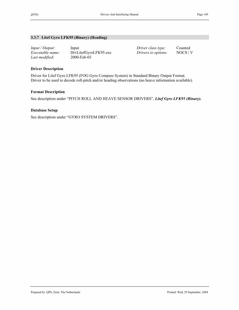
QINSy Drivers And Interfacing Manual Page 149
Prepared by: QPS, Zeist, The Netherlands Printed: Wed, 29 September, 2004
3.3.7 Litef Gyro LFK95 (Binary) (Heading)
Input / Output: Input Driver class type: Counted Executable name: DrvLitefGyroLFK95.exe Drivers.io options: NOCS | V Last modified: 2000-Feb-03
Driver Description
Driver for Litef Gyro LFK95 (FOG Gyro Compass System) in Standard Binary Output Format. Driver to be used to decode roll-pitch and/or heading observations (no heave information available).
Format Description
See description under “PITCH ROLL AND HEAVE SENSOR DRIVERS”, Litef Gyro LFK95 (Binary).
Database Setup
See description under “GYRO SYSTEM DRIVERS”.

QINSy Drivers And Interfacing Manual Page 150
Prepared by: QPS, Zeist, The Netherlands Printed: Wed, 29 September, 2004
3.3.8 NMEA Anschutz (HEHCC)
3.3.9 NMEA Gyrocompass (HEHDT)
3.3.10 NMEA Magnetic Heading (HDG/HDM/HCC/HCD)
3.3.11 NMEA True Heading Gyrocompass (HDG/HDT)
Input / Output: Input Driver class type: Terminated <LF> Executable name: DrvGyroNMEA.exe Drivers.io options: format | NOCS | OI Last modified: 1997-May-01
Driver Description
Driver for NMEA-0183 $--Hxx sentences, containing true and/or magnetic (gyro)compass heading data. $--HCC, $--HCD and $HDM sentences contain magnetic headings, $--HDT sentences contain true headings, $--HDG strings contain magnetic heading, deviation and varition, from which true headings can be obtained.
Format Description
Each $--Hxx sentence is variable in length, depending on the number of digits for the decoded heading(s). Refer to NMEA 0183- Standard For Interfacing Electronic Devices - Version 2.30 for more information. Format NMEA $HEHCC string:
# Format Description Values 01 “$” start character “$” (24 Hex) 02 aaccc address field “HEHCC” 03 “,” field delimiter “,” (2C Hex) 04 x.x compass heading (degrees) 05 “*” checksum field delimiter “*” (2A Hex) 06 hh checksum (XOR from “$” to “*” exclusive) 07 <CR><LF> termination characters <CR><LF> (0D Hex, 0A Hex)
Format NMEA $HEHDT string:
# Format Description Values 01 “$” start character “$” (24 Hex) 02 aaccc address field “HEHDT” 03 “,” field delimiter “,” (2C Hex) 04 x.x heading (degrees True) 05 “,” field delimiter “,” (2C Hex) 06 “T” heading (True) “T” 07 “*” checksum field delimiter “*” (2A Hex) 08 hh checksum (XOR from “$” to “*” exclusive) 09 <CR><LF> termination characters <CR><LF> (0D Hex, 0A Hex)
Database Setup
See description under “GYRO SYSTEM DRIVERS”.

QINSy Drivers And Interfacing Manual Page 151
Prepared by: QPS, Zeist, The Netherlands Printed: Wed, 29 September, 2004
3.3.12 SeaEye Boxer ROV (Heading)
Input / Output: Input Driver class type: Counted <LF> Executable name: DrvSeaEyeBoxer.exe Drivers.io options: none Last modified: 2004-May-18
Driver Description
Driver for decoding heading, depth and CP (Cathode Protection) voltage from a SeaEye Boxer Camera ROV.
Format Description
The system outputs a binary serial stream. The start of a new packet can be recognized by the two header bytes, 2B and 21 (hexadecimal). The various fields contain undimensioned raw values only. The driver will convert the values to a readable heading in degrees, depth in survey units and CP value in Volts.
# Format Description Values 01 Byte ID Byte 1 2Bh 02 Byte ID Byte 2 21h 03 Byte Length Typically 21 04 Byte ???? Always B4h 05 Byte Compass Status See below
06 -13 Bytes Unknown 0 14 Byte Sort of Sync Byte? Always F0h
15 + 16 WORD Compass Value (10 Least Sig. Bits) 0-1024 17+18 WORD Depth Value 0-65535 19+20 WORD CP Value 0-2048
21 Byte Pan ???? 22 Byte Tilt ????
23+24 WORD Checksum from #04 up to #22 [Sum] 0-65535 Note: All integers are Intel Byte ordered {LSB, MSB}
Decoding Notes
The Driver will only properly decode the values if the checksum is correct. If checksum is invalid then the driver will not output any data! The following formulas were used inside the driver to convert the values: Heading = Value * 360 /1024 Depth Frequency = 750 * 65535 / (65535 – Value) Depth in Feet = (Depth Frequency – 1000) * 1123 / 5000 Cp Voltage = (Value – 2048) * 2.5 / 2048

QINSy Drivers And Interfacing Manual Page 152
Prepared by: QPS, Zeist, The Netherlands Printed: Wed, 29 September, 2004
Quality Indicators: The status of the Compass is translated to a readable Quality Indicator: Status: Value: QINSy Quality
Indicator NotCalibrated '0' -6 CalStart '1', -5 FieldTooLarge '2' -4 FieldTooWeak '3' -3 CorrTooLarge '4' -2 InitInProgress 'R' -1 InitReady 'I' 0 Calibrated 'C' 1 The corresponding raw value is stored as the Quality indicator value for Depth and CP observations. Depth is always converted to the current survey units.
Database Setup
See description under “GYRO SYSTEM DRIVERS”. -Add a “Gyro” system, and select this driver. Select a COM port and setup communication parameters. Add an “Underwater Sensor” system to decode the depth value from the message, and select the “Depth – SeaEye Boxer ROV” system. Select the same COM port as the Gyro system. Select an ROV Depth Observation and the appropriate node set the unit to “Survey Unit”. -Add a “Miscellaneous” system if the CP Value must be decoded too. Select the same COM port as the Gyro system. Add an observation with a scale factor of 1.000 if you require the CP value in volts. Choose for all these systems the same COM port, this way all systems will be supported by one driver program.

QINSy Drivers And Interfacing Manual Page 153
Prepared by: QPS, Zeist, The Netherlands Printed: Wed, 29 September, 2004
3.3.13 SG-Brown 1000-A Gyrocompass (ASCII Heading)
Input / Output: Input Driver class type: Terminated <LF> Executable name: DrvGyroSGBASCII.exe Drivers.io options: none Last modified: 1999-May-06
Driver Description
Driver for decoding 1/6th degree ASCII heading data strings from SG-Brown 1000-A/SG-Brown Meridian Surveyor and SG-Brown S1000 gyro’s.
Format Description
Each ASCII heading data string represents an azimuth (true heading) with a resolution of 0.1667 degree, and is terminated by <CR><LF>. An example of an ASCII data string from a gyrocompass is given below. 2512<CR><LF> 251.333 degrees (251 + 2 / 6)
# Format Description Values 01 Xxxx compass heading (0.167 degrees) 0000 – 3599 02 <CR><LF> termination characters <0x13><0x10>
Database Setup
See description under “GYRO SYSTEM DRIVERS”.

QINSy Drivers And Interfacing Manual Page 154
Prepared by: QPS, Zeist, The Netherlands Printed: Wed, 29 September, 2004
3.3.14 Sperry Gyrocompass (ASCII Heading)
Input / Output: Input Driver class type: Terminated <LF> Executable name: DrvGyroSperry.exe Drivers.io options: none Last modified: 1998-Apr-29
Driver Description
Driver for decoding ASCII heading data strings from Sperry gyro's. Driver for decoding 1/10th degree ASCII heading data strings from SG-Brown 1000-A/SG-Brown Meridian Surveyor and SG-Brown S1000 gyro’s.
Format Description
Each ASCII heading data string represents an azimuth (true heading) with a resolution of 0.1 degree, and is terminated by <CR><LF>. An example of an ASCII data string from a Sperry gyrocompass is given below. 0138<CR><LF> 13.8 degrees
# Format Description Values 01 xxxx compass heading (0.1 degrees) 0000 – 3599 02 <CR><LF> termination characters <0x13><0x10>
Database Setup
See description under “GYRO SYSTEM DRIVERS”.

QINSy Drivers And Interfacing Manual Page 155
Prepared by: QPS, Zeist, The Netherlands Printed: Wed, 29 September, 2004
3.3.15 UDI Nav Header Heading
Input / Output: Input Driver class type: Terminated <LF> Executable name: DrvHdrUDINav.exe Drivers.io options: none Last modified: 1999-May-31
Driver Description
Driver for old and new UDI header telegrams. Driver is cable of decoding grid position as well as grid heading from three different telegrams as found in the UDI software. The following formats are supported: - UDI Nav Header - Fugro UDI Surface Position Telegram - Fugro UDI Acoustic Position Telegram For format details see UDI Nav Header Position description. All headings mentioned in the formats are grid headings that are converted to true heading by the driver.
Database Setup
See description under “GYRO SYSTEM DRIVERS”. Driver can also be used together with the UDI Nav Header Position driver. See description for details.

QINSy Drivers And Interfacing Manual Page 156
Prepared by: QPS, Zeist, The Netherlands Printed: Wed, 29 September, 2004
(this page intentionally left blank)

QINSy Drivers And Interfacing Manual Page 157
Prepared by: QPS, Zeist, The Netherlands Printed: Wed, 29 September, 2004
3.4 PITCH, ROLL AND HEAVE SENSOR DRIVERS
Database Setup
First define and select the “Object” on which the MRU (Motion Reference Unit) is located. Add a new system of type “Pitch, roll and heave sensor”. Select the appropriate driver and interface parameters. Press “Next” button to finish the setup. There is no need to define the three pitch, roll and heave observations separately, since they are automatically added to the system. Select the node for which the observations are valid, i.e. lever arm node if motion data is not corrected to the vessel reference point and the reference node if the data are corrected before output. If the MRU node has got a non-zero offset, then QINSy will apply a so-called lever arm correction for pitch and roll induced heave. Change the parameters to match the rotation sign convention and measurement units of the format description. Finally, press “Finish” to save the system or press “Next” first to enter some administrative information about the quality indicators that are decoded.

QINSy Drivers And Interfacing Manual Page 158
Prepared by: QPS, Zeist, The Netherlands Printed: Wed, 29 September, 2004
Database Setup (continued)
A new MRU node can be added by pressing the button; to change its properties, press the button.
See for more information the QINSy DB Setup Help Topics or the QINSy Knowledge Base.

QINSy Drivers And Interfacing Manual Page 159
Prepared by: QPS, Zeist, The Netherlands Printed: Wed, 29 September, 2004
3.4.1 Atlas Dynabase C R-P-H (0.0055 deg)
3.4.2 Atlas Dynabase C R-P-H (0.0100 deg) Input / Output: Input Driver class type: Counted Executable name: DrvAtlasMRUDynabaseC.exe Drivers.io options: DynaC NEW Last modified: 2003-Apr-04
Driver Description
Driver for Atlas MRU (Motion Reference Unit) binary messages in Dynabase C format. Driver to be used to decode roll-pitch-heave observations.
Format Description
The Standard Atlas binary message is a string of 9 bytes according to the following format: SRrPpHhQS 123456789
Field Definition Units Value S Start character (ASCII 10 Hex) - - Rr Roll – MSB & LSB (**) Pp Pitch – MSB & LSB (**) Hh Heave – MSB & LSB 1 cm Q Status code - 0 – 7 (*) S Stop character (ASCII 10 Hex) - -
(*) = see following table (**) = The unit may be either 0.0100° or approximately 0.0055° depending on the driver version used
Status Code
Mode Description Condition
0 Unaided No input (bad data) Settled 1 Unaided No input (***) Settling 2 GPS Aided Input from GPS Settled 3 GPS Aided Input from GPS (***) Settling 4 Heading Aided Input from Gyro Settled 5 Heading Aided Input from Gyro (***) Settling 6 Full Aided Input from GPS and Gyro Settled 7 Full Aided Input from GPS and Gyro (***) Settling
(***) = still awaiting end of 3 min. settling period after Dynabase C power-on or a mode change. Fixed length message, using single-byte, 16-bit 2-complement numbers. MSB is transmitted first for the multi-byte elements. The sign convention is such that +ve heave is above datum (meaning upwards), +ve pitch is bow up and +ve roll is port side up.
Database Setup
See description under “PITCH ROLL AND HEAVE SENSOR DRIVERS”.

QINSy Drivers And Interfacing Manual Page 160
Prepared by: QPS, Zeist, The Netherlands Printed: Wed, 29 September, 2004
3.4.3 Hippy Datawell Piro MRU Input / Output: Input Driver class type: Terminated <LF> Executable name: DrvDatawellPiro.exe Drivers.io options: A | B | C | D Last modified: 1998-Jun-02
Driver Description
Driver for Hippy Datawell Piro (Motion Reference Unit) ASCII message. Driver to be used to decode roll-pitch-heave observations and or the heading. To date, QPS has only experienced the four analogue outputs from Datawell Piro unit in volts passed through an Analogue-Digital converter that outputs an ASCII string.
Format Description SA.AAA SB.BBB SC.CCC SD.DDD<CR><LF> S Sign (+ or -) A Digit (0..9) from channel A B Digit (0..9) from channel B C Digit (0..9) from channel C D Digit (0..9) from channel D <CR><LF> CarriageReturn + LineFeed The length is 29 bytes, inclusive <CR><LF>. The Roll and Pitch values are 10 times the ARCSIN, the Heave is in centimetres, whilst the Heading is in radians. Which value is on which channel depends upon how the Datawell Piro is connected to the ADC unit.
Format Example 9.174 -0.156 -0.019 +9.125 9.150 -0.146 -0.019 +9.101 9.145 -0.141 -0.029 +9.096 9.150 -0.141 -0.014 +9.096
Database Setup
See description under “PITCH ROLL AND HEAVE SENSOR DRIVERS”. To decode the heading, add a “System” of type “Gyro”, select the driver, and define the heading parameters. To decode all four observations (pitch, roll, heave and heading), add both these system types to the QINSy database and make sure to select the same driver name and the same I/O parameters for both systems.

QINSy Drivers And Interfacing Manual Page 161
Prepared by: QPS, Zeist, The Netherlands Printed: Wed, 29 September, 2004
3.4.4 iXSea /Photonetics Octans MRU ($PHTRH / $PHTRO) Input / Output: Input Driver class type: Terminated <LF> Executable name: DrvPhotoneticsOctans.exe Drivers.io options: U | O | NOCS Last modified: 2004-Jul-16
Driver Description
Driver for iXSea (previously Photonetics) Octans solid state VRU NMEA messages $PHTRH or $PHTRO and/or $PHSPD and/or $HEHDT, referred to in the manuals as GYROCOMPAS 2. Output type. Driver to be used to decode roll-pitch-heave observations, local speeds and/or heading.
Format Description
The $HEHDT message is exactly the NMEA0183 sentence, $HEHDT - True Heading $HEHDT,x.x,T[*hh]<CR><LF> Heading: x.x value The $PHTRH message is a proprietary NMEA0183 sentence, $PHTRH - Pitch, Roll, Heave $PHTRH,x.x,c,x.x,c,x.x,c[*hh]<CR><LF> Pitch: x.x absolute value Sign of pitch: c M=Up P=Down Convention: + M BOW UP Roll: x.x absolute value Sign of roll: c B=Portside Down T=Starboard Down Convention: + T PORT UP Heave: x.x absolute value Sign of heave: c O=Plus U=Minus or U=Plus O=Minus (see remark on firmware version) Convention: + O UP or U Up The $PHTRO message is a proprietary NMEA0183 sentence, $PHTRO - Pitch, Roll $PHTRO,x.x,c,x.x,c[*hh]<CR><LF> Pitch: x.x absolute value Sign of pitch: c M=Up P=Down Convention: + M BOW UP Roll: x.x absolute value Sign of roll: c B=Portside Down T=Starboard Down Convention: + T PORT UP

QINSy Drivers And Interfacing Manual Page 162
Prepared by: QPS, Zeist, The Netherlands Printed: Wed, 29 September, 2004
The $PHSPD message is a proprietary NMEA0183 sentence, $PHSPD – X1, X2 and X3 speed $PHSPD,x.xxx,y.yyy,z.zzz[*hh]<CR><LF> Speed across centerline unit: x.xxx m/s signed value Speed along centerline unit: y.yyy m/s signed value Speed along vertical axis unit: z.zzz m/s signed value
Firmware Versions
The Photonetic manuals used to describe that 'U' is plus for heave up, but when older Octans systems were lifted, the heave sign character used to be 'O'. In recent firmware versions, this problem has been solved, so iXSea Octans systems will output a ‘U’ when the Octans is lifted, which corresponds to the manuals. QPS is not sure in which firmware version this problem has been solved, but Photonetics has confirmed us that Octans firmware 4.6, or higher, should be according to the “Heave Up ‘U’ conventions. Use the I/O Test Utitlity in QINSy to check which is the output character when the Octans is lifted, ‘U’ or ‘O’.
Drivers.io Options
Command line parameter “U” will decode a ‘U’ heave sign as heave up, whereas parameter “O” will decode a ‘O’ heave sign as heave up. “NOCS” will not decode and test the checksum field in the messages.
Database Setup
See description under “PITCH ROLL AND HEAVE SENSOR DRIVERS”. To decode the heading, add a “System” of type “Gyro”, select the driver, and define the heading parameters. To decode all four observations (pitch, roll, heave and heading), add both these system types to the QINSy database and make sure to select the same gyro driver as the MRU driver (regarding the heave convention) and the same I/O parameters for both systems.

QINSy Drivers And Interfacing Manual Page 163
Prepared by: QPS, Zeist, The Netherlands Printed: Wed, 29 September, 2004
3.4.5 iXSea Phins standard ($HEHDT) / ($PIXSE,ATITUDE, ~POSITI, ~SPEED_) Input / Output: Input Driver class type: Terminated <LF> Executable name: DrvIxseaPhins.exe Drivers.io options: none Last modified: 2003-01-06
Driver Description
This driver decodes iXSea Phins standard output protocol messages. The Phins standard output protocol messages are NMEA 0183 compatible. The driver is capable of decoding messages concerning: heading, attitude, position, speed, standard deviations and the Phins status.
Format Description
Heading – $HEHDT,x.xx,T*hh<CR><LF>
Field Format Description Values, Range, Units 1 $HEHDT Message type identifier “$HEHDT” 2 x.xx True heading 0.00…360.00 (degrees) 3 T “T” 4 *hh Checksum XOR from “$” to “*” exclusive 5 <CR><LF> Termination characters <CR><LF> (0D Hex, 0A Hex)
$HEHDT,49.732,T*14
Roll and Pitch – $PIXSE,ATITUD,x.xx,y.yy*hh<CR><LF>
Field Format Description Values, Range, Units 1 $PIXSE,ATITUD Message type identifier “$PIXSE,ATITUD” 2 x.xx Roll Degrees (positive heeling to starboard)3 y.yy Pitch Degrees (positive bow down) 4 *hh Checksum XOR from “$” to “*” exclusive 5 <CR><LF> Termination characters <CR><LF> (0D Hex, 0A Hex)
$PIXSE,ATITUD,-0.588,0.474*4D
Speed – $PIXSE,SPEED_,x.xx,y.yy,z.zz*hh<CR><LF>
Field Format Description Values, Range, Units 1 $PIXSE, SPEED_ Message type identifier “$PIXSE, SPEED_” 2 x.xx North speed Meters / second 3 y.yy West speed Meters / second 4 z.zz Vertical speed Meters / second 5 *hh Checksum XOR from “$” to “*” exclusive 6 <CR><LF> Termination characters <CR><LF> (0D Hex, 0A Hex)
$PIXSE,SPEED_,0.0000,0.0000,0.0000*51

QINSy Drivers And Interfacing Manual Page 164
Prepared by: QPS, Zeist, The Netherlands Printed: Wed, 29 September, 2004
Position – $PIXSE,POSITI,x.xx,y.yy,z.zz*hh<CR><LF>
Field Format Description Values, Range, Units 1 $PIXSE, POSITI Message type identifier “$PIXSE, POSITI” 2 x.xx Latitude Degrees 3 y.yy Longitude Degrees 4 z.zz Altitude meters 5 *hh Checksum XOR from “$” to “*” exclusive 6 <CR><LF> Termination characters <CR><LF> (0D Hex, 0A Hex)
$PIXSE,POSITI,48.87000648,0.99997750,3.490*53
Position Standard Deviation – $PIXSE,STDPOS,x.xx,y.yy,z.zz*hh<CR><LF>
Field Format Description Values, Range, Units 1 $PIXSE, STDPOS Message type identifier “$PIXSE, STDPOS ” 2 x.xx Latitude standard deviation 3 y.yy Longitude standard deviation 4 z.zz Altitude standard deviation 5 *hh Checksum XOR from “$” to “*” exclusive 6 <CR><LF> Termination characters <CR><LF> (0D Hex, 0A Hex)
$PIXSE,STDPOS,50.000,50.000,50.000*43
Phins Status – $PIXSE,STATUS,hhhhhhhh*hh<CR><LF>
Field Format Description Values, Range, Units 1 $PIXSE, STDPOS Message type identifier “$PIXSE, STDPOS ” 2 hhhhhhhh Phins status hexadecimal 3 *hh Checksum XOR from “$” to “*” exclusive 4 <CR><LF> Termination characters <CR><LF> (0D Hex, 0A Hex)
$PIXSE,STATUS,30000000*40

QINSy Drivers And Interfacing Manual Page 165
Prepared by: QPS, Zeist, The Netherlands Printed: Wed, 29 September, 2004
The hexadecimal value of the Phins status is decoded as follows.
Bit Description Bit Description 0 Log valid 16 Serial input A error 1 GPS valid 17 Serial input B error 2 Depth valid 18 Serial input C error 3 USBL valid 19 FIFO full 4 Reserved 20 Serial output A full 5 Reserved 21 Serial output B full 6 Reserved 22 Serial output C full 7 Configuration saved to EEPROM 23 Reserved 8 FOG X1 Error 24 Serial input A activity 9 FOG X2 Error 25 Serial input B activity 10 FOG X3 Error 26 Serial input C activity 11 Optical source error 27 Reserved 12 Accelerometer X1 error 28 Heading not valid 13 Accelerometer X2 error 29 Attitude not valid 14 Accelerometer X3 error 30 User control flag 15 Sensor error memory 31 System restarted
Decoding Notes
The speed vectors decoded from the “$PIXSE,SPEED_” message are converted to one vertical speed vector, a horizontal speed vector and it’s heading. It is necessary that the complete “Phins Standard” is sent, in order to decode any data.
Database Setup
To decode the messages mentioned above four systems have to be chosen from in the Db Setup.
• Heading: Gyro’s and Compasses, iXSea Phins standard ($HEHDT) • Attitude: Pitch, Roll and Heave sensors, iXSea Phins standard ($PIXSE ATITUDE) • Position: Position Navigation System, iXSea Phins standard ($PIXSE POSITI) • Speed: Speed Log, iXSea Phins standard ($PIXSE SPEED_)
When one of the above drivers is chosen, the “Phins Status” message will be decode automatically. When the position is decoded, the “Position standard deviation” message will be decoded too.

QINSy Drivers And Interfacing Manual Page 166
Prepared by: QPS, Zeist, The Netherlands Printed: Wed, 29 September, 2004
3.4.6 Javad AT4 or IMU Unit (R-P) Input / Output: Input (two-way) Driver class type: Counted Executable name: DrvJavadAT4.exe Drivers.io options: None Last modified: 2004-June-15
Driver Description
Driver to decode message from Javad AT4 or from Javad IMU unit. These messages may contain attitude (roll, pitch and heading) data, external event markers, position (lat/lon/height) data, and/or sensors information data. Messages from the Javad AT4 that will be decoded are [AR] and/or [XA] records. These records are defined in the Topcon GPS Receiver Interface Language (GRIL) Manual, version 2.2. The [AR] records contain roll and pitch (no heave available!) and heading information The [XA] records contain the external event markers Messages from the Javad IMU unit that will be decoded are [ap], [SE], [po], and/or [at] records. The [ap] records contain roll and pitch (no heave available!), heading, and position information. The [SE] records contain sensor information (acceleration and angular velocities around the axis). The [po] records contain position information. The [at] records contain roll and pitch (no heave available!) and heading information. The driver will detect automatically the different message types.
Format Description
A GRIL output message consists of several different parts. The first part is a two byte record identifier followed by a 3 byte the record length field and the actual data record. The driver currently decodes the AR-message which contains the following fields
Field Format Description Values, Range, Units Identifier Char [2] Record identifier Always “AR” Length Char [3] Length coded as ASCII chars “015” hex = 21 bytes Time Integer GPS Time of day Milliseconds Pitch Float Pitch of local reference frame Degrees Roll Float Roll of local reference frame Degrees
Heading Float Heading of local reference frame Degrees Type Char [3] Solution type of each vector 3 = phase difference float
4 = phase difference fixed Flag Char Flags 0 = rotation angles are invalid
1 = rotation angles are valid CS Char Checksum

QINSy Drivers And Interfacing Manual Page 167
Prepared by: QPS, Zeist, The Netherlands Printed: Wed, 29 September, 2004
Decoding Notes
The solution type & checksum fields are not decoded. The flag field is decoded as the quality indicator. A zero value is decoded as –1 and a value of 1 is decoded as zero. Sign convention is +ve heading is clockwise, +ve pitch is bow up and +ve roll is starboard side down. The driver also decodes the XA-message which contains the following fields
Field Format Description Values, Range, Units Identifier Char [2] Record identifier Always “XA” Length Char [3] Length coded as ASCII chars “00A” hex = 10 bytes
ms Integer Millisecond part of event time tag Milliseconds ns Integer Nanosecond part of event time tag Nanoseconds
Scale Char Time scale 0 = GPS 1 = UTC_USNO 2 = GLONASS 3 = UTC_SU 4…254 = Reserved
CS Char Checksum
Decoding Notes
A generic observation is filled with value 0.0 and the observation time is set to the value decoded from the data. The quality indicator is set to the decoded scale.
Database Setup
See description under “PITCH ROLL AND HEAVE SENSOR DRIVERS”. To decode the heading, add a “System” of type “Gyro”, select the driver, and define the heading parameters. To decode all four observations (pitch, roll, heave and heading), add both these system types to the QINSy database and make sure to select the same driver name and the same I/O parameters for both systems. The unit for roll, pitch and heading must be set to Degrees To decode the event marker, add a “System” of type “Miscellenaous”, select the driver Javad AT4 Event Marker. Add a new generic observation and give it a correct name. If the roll, pitch or heading are also decoded, make sure that the same I/O parameters are selected for both systems.

QINSy Drivers And Interfacing Manual Page 168
Prepared by: QPS, Zeist, The Netherlands Printed: Wed, 29 September, 2004
3.4.7 KVH ROV GyroTrac (Pitch and Roll) Input / Output: Input Driver class type: Terminated <LF> Executable name: KVHROVGyroTrac.ini Drivers.io options: none Last modified: 2002-Jan-29
Driver Description
Driver for KVH ROV GyroTrac, ASCII string Driver to be used to decode roll-pitch and/or heading observations (no heave information available).
Format Description
ASCII String, fields are comma separated, Start Identifier character is “%” The first field contains the pitch value in tenth of degrees. The second field contains the roll value in tenth of degrees. The third field contains the heading in tenth of degrees
Example datastrings:
%-22,-21,1381 %-22,-21,1381 %-22,-21,1381 %-22,-21,1381 %-22,-22,1381 %-22,-22,1381
Database Setup
See description under “PITCH ROLL AND HEAVE SENSOR DRIVERS”. To decode the heading, add a “System” of type “Gyro”, select the driver, and define the heading parameters. To decode all observations (pitch, roll, and heading), add both these system types to the QINSy database and make sure to select the same driver name and the same I/O parameters for both systems.

QINSy Drivers And Interfacing Manual Page 169
Prepared by: QPS, Zeist, The Netherlands Printed: Wed, 29 September, 2004
3.4.8 Litef Gyro LFK95 (Binary) (Pitch-Roll) Input / Output: Input Driver class type: Counted Executable name: DrvLitefGyroLFK95.exe Drivers.io options: NOCS | V Last modified: 2000-Feb-29
Driver Description
Driver for Litef Gyro LFK95 (FOG Gyro Compass System) in Standard Binary Output Format. Driver to be used to decode roll-pitch and/or heading observations (no heave information available).
Format Description
The Standard Binary Output Message is a string of 20 bytes according to the following format. Element Comment Bytes Value Identifier 1 Hex 3 Heading 1) 3 0.000° – 359.995° (in units of 0.005493°) Roll 1) 3 -180.000° – 179.885° (in units of 0.005493°) Pitch 1) 3 -180.000° – 179.885° (in units of 0.005493°) X’Rate Not used 3 Y’Rate Not used 3 Z’Rate Not used 3 Checksum 3) 1 XOR, AND MASK
Comments. 1) The three bytes contain, besides the actual value, also the following information: • Mode flag 0 = GyroCompass, 2 = TestMode, 3 = Alignment Mode • SF flag 0 = System OK, 1 = System Failure • RG flag 0 = Specified Accuray, 1 = Reduced Accurary • Validity flag 0 = Data Invalid, 1 = Data Valid 2) If DRIVERS.IO command line parameter V is used, data is only updated when all flags are okay, i.e. Mode = 0, SF = 0, RG = 0, and Validity = 1 3) If DRIVERS.IO command line Parameter NOCS is used, the checksum of the message will be ignored. Sign convention is +ve heading is clockwise, +ve pitch is bow up and +ve roll is starboard side down.
Database Setup
See description under “PITCH ROLL AND HEAVE SENSOR DRIVERS”. To decode the heading, add a “System” of type “Gyro”, select the driver, and define the heading parameters. To decode all four observations (pitch, roll, heave and heading), add both these system types to the QINSy database and make sure to select the same driver name and the same I/O parameters for both systems.

QINSy Drivers And Interfacing Manual Page 170
Prepared by: QPS, Zeist, The Netherlands Printed: Wed, 29 September, 2004
3.4.9 Seatex Seapath MRU Binary Standard
3.4.10 Seatex Seapath MRU Binary Format11 Input / Output: Input Driver class type: Counted Executable name: DrvSeapathMRU.exe Drivers.io options: 11 | NOCS Last modified: 2001-Jan-07
Driver Description
Driver for Seatex Seapath/MRU binary messages in Standard, Format 11, EM1000 or EM3000 format. Driver to be used to decode roll-pitch-heave, heading and/or lat-lon-height observations from Seapath (or MRU) motion reference units. The EM1000 or EM3000 formats are covered by the Simrad driver.
Format Description
The Standard Seapath binary message is a string of 52 bytes according to the following format. Element Scale Units Format Bytes Value Header ASCII 1 ‘q’ Length unsigned 1 49 Token unsigned 1 0 - 255 Time integer 4 0 - 999999999 Latitude 90 / 2^30 ° integer 4 −2^30 - 2^30 Longitude 90 / 2^30 ° integer 4 −2^30 - 2^30 Height m float 4 Heave m float 4 North velocity m/s float 4 East velocity m/s float 4 Down velocity m/s float 4 Roll rad float 4 Pitch rad float 4 Heading rad float 4 0 - 2 PI Status bit-fields 4 Checksum unsigned 1 0 - 255
Fixed length message, using single-byte unsigned, four-byte 2-complement integer, four-byte ieee floating point data elements. MSB is transmitted first for the multi-byte elements. Length is number of bytes between length field and checksum field. Checksum is modulo 256 of all bytes between length and checksum. The sign convention is such that +ve heave is down, +ve pitch is bow up and +ve roll is port side up.
Decoding Notes
The Seapath MRU driver will reverse the sign of the heave so that +ve heave is up, as is standard in QINSy. All units are converted to meters and degrees, respectively. If a status bit for a Seapath observation type (i.e. position, heave, roll-pitch, or heading) is “invalid”, then the quality indicator is set to –1. If a status bit is “reduced” then the quality indicator is set to 0.11. If a status bit is OK, then the quality indicator is +1. If checksum fails, and data are still decoded (parameter “NOCS”), then quality indicator is set to –999. (continued on next page)

QINSy Drivers And Interfacing Manual Page 171
Prepared by: QPS, Zeist, The Netherlands Printed: Wed, 29 September, 2004
Format Description (continued)
The Seapath Format 11 binary message is a string of 42 bytes according to the following format. Element Scale Units Format Bytes Value Header ASCII 1 ‘q’ Time s integer 4 since 01-01-1970 Time 0.01 s unsigned 1 0 – 99 Latitude 90 / 2^30 ° integer 4 −2^30 - 2^30 Longitude 90 / 2^30 ° integer 4 −2^31 - 2^31 Height 0.01 m integer 4 Heave 0.01 m integer 2 North velocity 0.01 m/s integer 2 East velocity 0.01 m/s integer 2 Down velocity 0.01 m/s integer 2 Roll 90 / 2^14 ° integer 2 −2^15 - 2^15 Pitch 90 / 2^14 ° integer 2 −2^15 - 2^15 Heading 90 / 2^14 ° integer 2 0 - 2^16 Roll rate 90 / 2^14 °/s integer 2 −2^15 - 2^15 Pitch rate 90 / 2^14 °/s integer 2 −2^15 - 2^15 Yaw rate 90 / 2^14 °/s integer 2 −2^15 - 2^15 Status bit-fields 2 Checksum unsigned 2 16-bit CRC
See description under Standard Binary table on previous page for more information on format and decoding. The checksum, calculated as a 16-bit block Cyclic Redundancy Check of all bytes between, but not including the header and checksum fields, is currently not supported because QPS lacks a description of the algorithm.
Drivers.io Options
Command line parameter “11” will decode the “Format 11” data strings (length 42 bytes), otherwise the “Standard” data strings (52 bytes) are expected. Parameter “NOCS” for “Standard” format will continue decoding the data if the checksum value does not correspond to the actual data; quality is set to –999.
Database Setup
See description under “PITCH ROLL AND HEAVE SENSOR DRIVERS”. To decode the heading, add a “System” of type “Gyro”, select the driver, and define the heading parameters. To decode all four observations (pitch, roll, heave and heading), add both these system types to the QINSy database and make sure to select the same driver name and the same I/O parameters for both systems. To decode the position from the Seapath binary data string, add a “System” of type “Position Navigation System”, select the Seatex Seapath driver, and define the antenna node and reference datum. To decode all possible observations (pitch, roll, heave, heading and position), add all three types of system types to the QINSy database and make sure to select the same driver and the same I/O parameters for all systems.
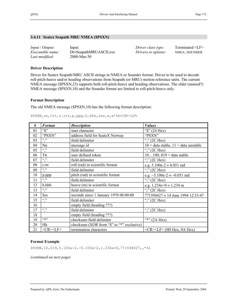
QINSy Drivers And Interfacing Manual Page 172
Prepared by: QPS, Zeist, The Netherlands Printed: Wed, 29 September, 2004
3.4.11 Seatex Seapath MRU NMEA ($PSXN) Input / Output: Input Driver class type: Terminated <LF> Executable name: DrvSeapathMRUASCII.exe Drivers.io options: NMEA | SOUNDER Last modified: 2000-Mar-30
Driver Description
Driver for Seatex Seapath/MRU ASCII strings in NMEA or Sounder format. Driver to be used to decode roll-pitch-heave and/or heading observations from Seapath (or MRU) motion reference units. The current NMEA message ($PSXN,23) supports both roll-pitch-heave and heading observations. The older (unused?) NMEA message ($PSXN,10) and the Sounder format are limited to roll-pitch-heave only.
Format Description
The old NMEA message ($PSXN,10) has the following format description: $PSXN,nn,ttt,r.rrr,p.ppp,h.hhh,sss,x,x*hh<CR><LF>
# Format Description Values 01 “$” start character “$” (24 Hex) 02 “PSXN” address field for SeateX Norway “PSXN” 03 “,” field delimiter “,” (2C Hex) 04 Nn message id 10 = data stable, 11 = data unstable 05 “,” field delimiter “,” (2C Hex) 06 Ttt user defined token 10…100; 019 = data stable 07 “,” field delimiter “,” (2C Hex) 08 r.rrr roll (rad) in scientific format e.g. 5.100e-2 ≡ 0.051 rad 09 “,” field delimiter “,” (2C Hex) 10 p.ppp pitch (rad) in scientific format e.g. −5.100e-2 ≡ −0.051 rad 11 “,” field delimiter “,” (2C Hex) 12 h.hhh heave (m) in scientific format e.g. 1.234e+0 ≡ 1.234 m 13 “,” field delimiter “,” (2C Hex) 14 Sss seconds since 1 January 1970 00:00:00 771598427 ≡ 14 June 1994 12:53:47 15 “,” field delimiter “,” (2C Hex) 16 empty field (heading ???) 17 “,” field delimiter “,” (2C Hex) 18 empty field (heading ???) 19 “*” checksum field delimiter “*” (2A Hex) 20 Hh checksum (XOR from “$” to “*” exclusive) 21 <CR><LF> termination characters <CR><LF> (0D Hex, 0A Hex)
Format Example $PSXN,10,019,5.100e-2,-5.100e-2,1.234e+0,771598427,,*61 (continued on next page)

QINSy Drivers And Interfacing Manual Page 173
Prepared by: QPS, Zeist, The Netherlands Printed: Wed, 29 September, 2004
The current NMEA message ($PSXN,23) has the following format description: $PSXN,nn,r.rr,p.pp,d.dd,h.hh*hh<CR><LF>
# Format Description Values 01 “$” Start character “$” (24 Hex) 02 “PSXN” Address field for SeateX Norway “PSXN” 03 “,” Field delimiter “,” (2C Hex) 04 Nn message id Always 23 05 “,” Field delimiter “,” (2C Hex) 06 r.rr Roll in degrees (positive with port side up) 07 “,” Field delimiter “,” (2C Hex) 08 p.pp Pitch in degrees (positive with bow up) 09 “,” Field delimiter “,” (2C Hex) 10 d.dd True heading in degrees Between 0.00 and 359.99 11 “,” Field delimiter “,” (2C Hex) 12 h.hh Heave in meters (positive down) 13 “,” Field delimiter “,” (2C Hex) 17 “*” Checksum field delimiter “*” (2A Hex) 18 Hh Checksum (XOR from “$” to “*”
exclusive)
19 <CR><LF> Termination characters <CR><LF> (0D Hex, 0A Hex)
Format Example $PSXN,23,2.36,3.86,5.02,0.00*35
Database Setup
See description under “PITCH ROLL AND HEAVE SENSOR DRIVERS”. To decode the heading, add a “System” of type “Gyro”, select the driver, and define the heading parameters. To decode all four observations (pitch, roll, heave and heading), add both these system types to the QINSy database and make sure to select the same driver name and the same I/O parameters for both systems

QINSy Drivers And Interfacing Manual Page 174
Prepared by: QPS, Zeist, The Netherlands Printed: Wed, 29 September, 2004
3.4.12 Seatex Seapath MRU Sounder Sentence Input / Output: Input Driver class type: Terminated <LF> Executable name: DrvSeapathMRUASCII.exe Drivers.io options: NMEA | SOUNDER Last modified: 2000-Mar-30
Driver Description
Driver for Seatex Seapath (or MRU) ASCII messages in NMEA or Sounder format. Driver to be used to decode roll-pitch-heave observations from Seapath (or MRU) motion reference units. Opposite to the binary Seatex Seapath output formats, there is no heading observation included in this ASCII message.
Format Description
The Sounder Sentence protocol has format (length is 27 bytes): :aabbbb shhhhxsrrrr spppp<CR><LF>
# Format Description Values or Scale 01 “:” start character “:” (3A Hex) 02 aa 2 character Hex number sway acceleration 0.03835 m/ss 03 bbbb 4 character Hex number heave acceleration 0.000625 m/ss 04 “ “ space character “ ” (20 Hex) 05 s heave sign “−” (2D Hex) or “ ” (20 Hex) 06 hhhh heave in 0.01 metres +ve is upwards 07 x warning character “?” (3F Hex) for unstable data 08 s roll sign “−” (2D Hex) or “ ” (20 Hex) 09 hhhh roll in 0.01 degrees e.g. 0087 ≡ 0.87 ° 10 “ “ space character “ ” (20 Hex) 11 s pitch sign “−” (2D Hex) or “ ” (20 Hex) 12 hhhh pitch in 0.01 degrees e.g 0378 ≡ 3.78 ° 13 <CR><LF> termination characters <CR><LF> (0D Hex, 0A Hex)
Format Example :1a36b0 -0254 -0087 0378
Database Setup
See description under “PITCH ROLL AND HEAVE SENSOR DRIVERS”.

QINSy Drivers And Interfacing Manual Page 175
Prepared by: QPS, Zeist, The Netherlands Printed: Wed, 29 September, 2004
3.4.13 Sercel 230 Heading, Roll and Pitch Input / Output: Input Driver class type: Terminated <LF> Executable name: DrvNR103NMEA.exe Drivers.io options: format Last modified: 1997-May-01
Driver Description
Driver to be used to decode roll-pitch-heave and/or heading from NR 230 $A and $PSER,ATT strings.
Format Description
# Format Description Values or Scale 01 “$PSER,ATT” identifier 02 “,” field terminator 03 hhmmss.sss time of data, hours, minutes, seconds 00..23, 00..59, 00..59.99 04 “,” field terminator 05 dd day 00..31 06 “,” field terminator 07 mm month 00..12 08 “,” field terminator 09 yyyy year 0000..9999 10 “,” field terminator 11 hhh.h True heading degrees 12 “,” field terminator 13 “T” True heading indicator “T” 14 “,” field terminator 15 xx.xx Roll degrees 16 “,” field terminator 17 xx.xx Pitch degrees 18 “,” field terminator 19 IGNORED 20 <CR><LF> String terminator <CR><LF> (0D Hex, 0A Hex) # Format Description Values or Scale 01 “$A” identifier 02 “,” field terminator 03 s.s Delta time seconds 04 “,” field terminator 08 hhh.h True heading degrees 04 “,” field terminator 09 “T” True heading indicator “T” 04 “,” field terminator 10 xx.xx Roll degrees 04 “,” field terminator 11 xx.xx Pitch degrees 04 “,” field terminator 12 x unknown, IGNORED <CR><LF> string terminator CR><LF> (0D Hex, 0A Hex)
(continued on next page)

QINSy Drivers And Interfacing Manual Page 176
Prepared by: QPS, Zeist, The Netherlands Printed: Wed, 29 September, 2004
Format Example $PSER,ATT,215816.200,30,08,1997,+220.73,T,+00.54,-0.41,00.8,09>05,015,0 $A,0.1,+220.73,T,+00.54,-00.41,0
Database Setup
See description under “PITCH ROLL AND HEAVE SENSOR DRIVERS”. To decode the heading, add a “System” of type “Gyro”, select the driver, and define the heading parameters. To decode all four observations (pitch, roll, heave and heading), add both these system types to the QINSy database and make sure to select the same driver name and the same I/O parameters for both systems.

QINSy Drivers And Interfacing Manual Page 177
Prepared by: QPS, Zeist, The Netherlands Printed: Wed, 29 September, 2004
3.4.14 Simrad EM1000 (R-P-H)
3.4.15 Simrad EM3000 (R-P-H) Input / Output: Input Driver class type: Counted Executable name: DrvSimradMRU.exe Drivers.io options: EM1000 | EM3000 | OI Last modified: 2002-Dec-24
Driver Description
Driver to be used to decode roll-pitch-heave observations from motion reference units outputting data in the Simrad EM1000 or EM3000 format.
Format Description
The Simrad EM1000 and EM3000 message is a binary string of 10 bytes according to the following format. Element Scale Units Format Bytes Range Status unsigned 1 (1)(2) Header unsigned 1 90h Roll 0.01 ° integer 2 −9000 – 9000(3) Pitch 0.01 ° integer 2 −9000 – 9000(3) Heave 0.01 m integer 2 −2000 – 2000(3) Heading 0.01 ° unsigned 2 0 – 35999(3)
(1) EM1000: always 00h (2) EM3000: status byte can have values using following convention:
• 90h: Valid measurements with full accuracy • 91h to 99h: Valid measurements with reduced accuracy (decreasing
accuracy with increasing number) • 9Ah to 9Fh: Non-valid measurements but normal operation (i.e.
configuration or calibration mode) • A0h to AFh: Non-valid measurements with sensor error status
(3) If a value outside the range is detected the observation is rejected by the driver. In this case the last valid value will be remembered and the quality indicator will be set to -1.0.
Note. The sign convention is such that ‘+ve’ pitch is bow up and ‘+ve’ roll is port side up.
Decoding Notes
For both message types s the status field is used to set the quality indicator. For the EM1000 message the quality indicator is set to 1.00 when a 00h byte is encountered and a –1.00 if any other bytes is encountered. For the EM3000 message the quality indicator is set using the following table:
Status Byte Quality Indicator
90h 1.00 91h – 9Fh +1.10 to +2.50 (step size 0.10) A0h - AFh -1.00 to -2.50 (step size 0.10)
Other -1.00

QINSy Drivers And Interfacing Manual Page 178
Prepared by: QPS, Zeist, The Netherlands Printed: Wed, 29 September, 2004
Drivers.io Options
Command line parameters “EM1000” and “EM3000” indicate the message type as being decoded. “OI” indicates that the timetags are obtained from preceding “OiSTAR” headers, if available. Otherwise the first incoming byte is timetagged.
Database Setup
See description under “PITCH ROLL AND HEAVE SENSOR DRIVERS”.

QINSy Drivers And Interfacing Manual Page 179
Prepared by: QPS, Zeist, The Netherlands Printed: Wed, 29 September, 2004
3.4.16 TSS 320 / 335 / DMS-05 (R-P-H) Input / Output: Input (one-way) Driver class type: Counted Executable name: DrvTSSNew.exe Drivers.io options: OCTANS | OI Last modified: 2000-Dec-05 320 | DMS
Driver Description
Driver to be used to decode roll-pitch-heave observations from TSS motion reference units.
Format Description
Decodable TSS messages are ASCII strings according to the TSS1 or TSS3 format. Both formats contain 27 characters, including start and end fields. All fields contain measurements in real-world units; accelerations are supplied in ASCII-coded hexadecimal values and heave, roll and pitch as ASCII-coded decimal values. TSS1 PACKET :XXAAAA_MHHHHQMRRRR_MPPPPZZ
Field Format Description Range Units 01 “:” start of packet character “:” 3A Hex 02 XX horizontal acceleration 0 to 9.81 m/s² 3.83 cm/s² 03 AAAA vertical acceleration –20.48 to +20.47 m/s² 0.0625 cm/s² 04 _ space character “ “ 20 Hex 05 MHHHH heave –99 to +99 m 0.01 m 06 Q status flag “u,U,g,G,H,f,F”, “?”, “ “ see note 07 MRRRR roll –99 to +99 ° 0.01 ° 08 _ space character “ “ 20 Hex 09 MPPPP pitch –99 to +99 ° 0.01 ° 10 ZZ termination characters <CR><LF> 0D Hex 0A Hex
TSS3 PACKET :RMhhhh_MHHHHQMRRRR_MPPPPZZ
Field Format Description Range Units 01 “:” start of packet character “:” 3A Hex 02 “R” remote heave identifier “R” 52 Hex 03 Mhhhh remote heave –99 to +99 m 1 cm 04 _ space character “ “ 20 Hex 05 MHHHH heave –99 to +99 m 0.01 m 06 Q status flag “u,U,g,G,H,f,F”, “?”, “ “ see note 07 MRRRR roll –99 to +99 ° 0.01 ° 08 _ space character “ “ 20 Hex 09 MPPPP pitch –99 to +99 ° 0.01 ° 10 ZZ termination characters <CR><LF> 0D Hex 0A Hex
Signs. M is space if positive or minus if negative. Heave. Positive heave is above datum (upwards). Roll. Positive roll is port-side up, starboard down. Pitch. Positive pitch is bow up, stern down. Status. “U”,”G”,”H”,”F” indicate a settled condition; “u”,”g”,”h”,”f” are given during the 3 minutes settling period. “U” is unaided mode,”G” is GPS aided mode, ”H” is heading aided mode, ”F” is full aided mode. For TSS 320 messages, the status field is used to indicate heave quality control: space = OK, “?” = FAIL.

QINSy Drivers And Interfacing Manual Page 180
Prepared by: QPS, Zeist, The Netherlands Printed: Wed, 29 September, 2004
Format Examples :003D50 0000 1482 0085 :003D4E 0000 -1490 0065 :003D51 -0005 -0037 0074
Decoding Notes
Accelerations and remote heave data (fields 2 and 3 in both formats) are not decoded by the QINSy driver. The status or heave reliability field value is used to set the quality indicator. Quality +1 means reliable data. If a “?” is encountered at position 14, then the quality of the heave observation is set to –1. If the status field contains a “u”,”g”,”h” or ”f” (small caps), then the quality indicators of heave, pitch and roll are set to –1.
Drivers.io Options
Command line parameters “320” and “DMS” indicate TSS unit types, but make no difference. “OCTANS” indicates a reversed heave value input; the driver will correct for this (!). “OI” indicates that the timetags are obtained from preceding “OiSTAR” headers, if available. Otherwise the first incoming byte is timetagged.
Database Setup
See description under “PITCH ROLL AND HEAVE SENSOR DRIVERS”.

QINSy Drivers And Interfacing Manual Page 181
Prepared by: QPS, Zeist, The Netherlands Printed: Wed, 29 September, 2004
3.5 USBL SYSTEM DRIVERS
Database Setup
First define and select the “Object” on which the USBL transducer is located and the “Object” on which the USBL transponders are located. Select the item “Systems” under the object with the USBL transducer and define a new system of type “USBL”. Select the appropriate driver and interface parameters. Press “Next” button to continue the setup. There is no need to define the three X, Y and Z observations separately, since they are automatically added and connected to the system. Select the node for which the USBL observations are valid, i.e. transducer node if USBL data is not corrected for vessel reference point and the reference node if the data are corrected before output, and enter the various conventions and corrections. Press “Next” button again to define various administrative definitions. Press “Next” button and add all available USBL targets. The slot number depends on the used transponder or responder. Finally, press “Finish” to save system.

QINSy Drivers And Interfacing Manual Page 182
Prepared by: QPS, Zeist, The Netherlands Printed: Wed, 29 September, 2004
Database Setup (continued)
A new transducer node can be added by pressing the button; to change its properties, press button.
Press “Help” or refer to the QINSy Knowledge Base to find detailed information on the corrections that are defined on the “USBL Parameters” page, especially section “USBL Clarification Of USBL Configuration”.

QINSy Drivers And Interfacing Manual Page 183
Prepared by: QPS, Zeist, The Netherlands Printed: Wed, 29 September, 2004
Database Setup (continued)
Selections you make on this page are for administrative purposes only, and are not actively used by QINSy.

QINSy Drivers And Interfacing Manual Page 184
Prepared by: QPS, Zeist, The Netherlands Printed: Wed, 29 September, 2004
Database Setup (continued)
A USBL target can be added by pressing the “Add” and buttons. First, enter all transponders and responders. Then select a target from the list of available nodes and press “OK” to add the new target.

QINSy Drivers And Interfacing Manual Page 185
Prepared by: QPS, Zeist, The Netherlands Printed: Wed, 29 September, 2004
Database Setup (continued)
The slot number depends on the used transponder or responder. See USBL driver description for details.
See for more information the QINSy DB Setup Help Topics or the QINSy Knowledge Base.

QINSy Drivers And Interfacing Manual Page 186
Prepared by: QPS, Zeist, The Netherlands Printed: Wed, 29 September, 2004
(this page intentionally left blank)

QINSy Drivers And Interfacing Manual Page 187
Prepared by: QPS, Zeist, The Netherlands Printed: Wed, 29 September, 2004
3.5.1 Crane Tool VanDerLeun (QATT/QXYZ) (dX dY dZ)
Input / Output: Input with User Interface Driver class type: Terminated <LF> Executable name: DrvCraneVanDerLeun.exe Drivers.io options: None Last modified: 2004-March-29
Driver Description
The Crane Tool VanDerLeun Driver decodes #QATT, #QXYZ and / or #QD messages from the Van Der Leun dredging computer that is mounted o/b cranes used for dredging. The dredging computer will deliver relative position, attitude and heading of one or more boom segments and the grab. QINSy will decode the position information as USBL, so it is not a real USBL system. The driver has got a user-interface for assign the VRU systems to the slot information, this is not supported in DbSetup for these systems. The driver can decode three types of strings, the #QATT for heading and attitude, the #QXYZ for USBL and the #QD for the draught (“inzinking”). All strings contain a slot number. For the heading, USBL and Draught system you should enter a slot number in DbSetup. For the Attitude (VRU) system you should assign the slotnumber to a VRU system with the User interface. The relationships VRU system – slot number will be stored in the registry and are automatically retrieved when the driver starts. If the VRU system is not selected in the User Interface then it will not decode any VRU data!
Format Description
#QATT:
Field Format Description Values, Range, Units 01 #QATT Message type identifier “#QATT” 02 x Slot Identifier 1..255 03 x Relative Slot Identifier 0..255 04 x.x Pitch 05 “T” Pitch mode T=True, E=Error 06 “U” Pitch sign U= + bow up, D= + bow down 07 x.x Roll 08 “T” Roll mode T=True, E=Error 09 “S” Roll sign S= + healing Stb, P= + healing Prt 10 x.x Heading 11 “R” Heading mode T=True, R=Relative to field 03, E=Error 12 “D” Pitch, Roll, Heading Unit D=Deg, G=Grad, R=Rad

QINSy Drivers And Interfacing Manual Page 188
Prepared by: QPS, Zeist, The Netherlands Printed: Wed, 29 September, 2004
13 <CR><LF> termination characters <CR><LF> (0D Hex, 0A Hex) Note: Fields are delimited by a comma separator. Example: #QATT,1,0,0.23,T,U,0.2,T,S,272.1,T,D<CR><LF> #QATT,2,1,-0.12,T,U,1.02,T,S,10.32,R,D<CR><LF> When the pitch / roll sensor fails following string will be the output; #QATT,2,1,-0.12,E,U,1.02,E,S,10.32,R,D<CR><LF> Or: #QATT,2,1,,E,U,,E,S,10.32,R,D<CR><LF> #QXYZ:
Field Format Description Values, Range, Units 01 #QXYZ Message type identifier “#QXYZ” 02 x Slot Identifier 0..255 04 x.x X + to starboard 05 x.x Y + to bow 06 x.x Z + to sky 07 “T” XYZ mode T=True 08 M Unit M=Meter, E=Error 13 <CR><LF> termination characters <CR><LF> (0D Hex, 0A Hex)
Note: Fields are delimited by a comma separator. Example: #QXYZ,3,12.3,-50.2,-6,T,M<CR><LF> #QD:
Field Format Description Values, Range, Units 01 #QD Message type identifier “#QD” 02 x Slot Identifier 0..255 04 x.x D - to sky 05 “T” XYZ mode T=True 06 M Unit M=Meter, E=Error 07 <CR><LF> termination characters <CR><LF> (0D Hex, 0A Hex)
Note: Fields are delimited by a comma separator. Example: #QD,1,1.3,T,M<CR><LF> Full Example: #QATT,1,0,0.23,T,U,1.02,T,S,,T,D<CR><LF> #QATT,2,1,-30.24,T,U,1.02,T,S,0,R,D<CR><LF> #QATT,3,2,-81.32,T,U,1.02,T,S,0,R,D<CR><LF> #QATT,4,3,0,T,U,0,T,S,10.32,R,D<CR><LF>
Decoding Notes
#QATT messages contain a parent slot id. This slot id may be used for relative heading mode. Heading can be relative or absolute. If relative, the heading is computed by adding the parent’s heading to the decoded

QINSy Drivers And Interfacing Manual Page 189
Prepared by: QPS, Zeist, The Netherlands Printed: Wed, 29 September, 2004
heading. If pitch/roll/heading error flag is set (character ‘E’) then Quality indicators will be set to –1 else Quality indicator is set to +1. Driver does not convert units or conventions. You should use the unit/convention settings in DbSetup.

QINSy Drivers And Interfacing Manual Page 190
Prepared by: QPS, Zeist, The Netherlands Printed: Wed, 29 September, 2004
Database Setup
See description under “USBL SYSTEM DRIVERS”. All Slot Numbers should be numerical! -Add a “Gyro” system, and select this driver. Select same COM port as the USBL system. Select appropriate slot number and units. - Add a “Pitch Roll and Heave” system, and select this driver. Select same com port as the USBL system. Select appropriate convention. Note: Slot numbers can not be entered here, do this when controller is started with the U/I of the driver. Add an “Underwater Sensor” system to decode the draught value from the #QD message, and select the “Depth – Crane ToolVanderLeun (QD)” driver. Add a ROV Depth observation and define its slot number. The unit must be meters. Choose for all these systems the same COM port and baudrate, this way all systems will be supported by one driver program.
Drivers.io Options
None

QINSy Drivers And Interfacing Manual Page 191
Prepared by: QPS, Zeist, The Netherlands Printed: Wed, 29 September, 2004
3.5.2 CutterSuction Tool VanDerLeun (dX dY dZ) Input / Output: Input with User Interface Driver class type: Terminated <CR> Executable name: DrvCutterAnalogUI.exe Drivers.io options: format | trigger Last modified: 2000-Jan-31
Driver Description
The CutterSuction Tool driver calculates a relative X, Y, and Z between two objects, a vessel (or ROV) and a CutterSuction head. It is not a real USBL system, but actually a pseudo USBL system. It receives via an A/D converter vertical and/or horizontal angles. The driver has got a user-interface to enter the range between the from object node and the to object node, (C-O) values, input units (and limits) and angle computation mode. The driver will use the slant range and the two angles to calculate the pseudo USBL dX, dY and dZ values. Presently, only the VanDerLeun format is supported (Installatiebouw Van Der Leun, Sliedrecht, Nederland). The VanDerLeun A/D converter sends four ASCII strings, containing vessel depth or draft (“inzinking”), vertical angle (“hoek ladder”), and two dummy strings which can be used for future driver extensions.
Format Description
The VanDerLeun format data strings contain 11 bytes, including <CR>, and start with an identifier. A 0 0 ± 0 0 0 . 0 0 <CR> 0 1 2 3 4 5 6 7 8 9 10 A 0 1 = vessel draft “inzinking” A 0 2 = vertical angle “hoekladder” A 0 3 = reserved for future extension A 0 4 = reserved for future extension If a sensor signal is not active, the input data will contain the string “NO_SIGN”, where ‘_’ denotes a space.
Decoding Notes
The values that are obtained from the input data strings, as well as the values used to compute the dX, dY, dZ values and the computed dX, dY, dZ values are shown in the driver window. When a value does not update, for example a depth reading “NO SIGN”, then the box is empty. In this case, the old input value is retained, but the quality indicator of the observation is set to –1, as can be seen in an Observation Physics Display.
Database Setup
See description under “USBL SYSTEM DRIVERS”. To compute dX, dY and dZ observations, create an new object, e.g. "Suction Head"; this will automatically add a reference node, which will be the "USBL target transponder". Subsequently, add a “USBL” system, select the driver "CutterSuction Tool format (dX, dY, dZ)", and set the appropriate serial RS232 parameters. On the USBL Parameters tabsheet, the Location should be the node at which the angles are measured. Set the Sign convention for Z-axis data to positive downward if vertical angles are measured positive downward. Set all alignments to "No". Set the Alignment corrections to 0, if input data limits are to be defined in the driver. Skip the Administrative Records tabsheet. On the Targets tabsheet, select the suction head reference node. (continued on next page)

QINSy Drivers And Interfacing Manual Page 192
Prepared by: QPS, Zeist, The Netherlands Printed: Wed, 29 September, 2004
Database Setup (continued)
In order to decode (also) the depth measurement, add a system of type “Surface navigation system” to the object on which the depth sensor is located. Select the "Depth - CutterSuction Tool VanderLeun" driver and interface parameters as with the USBL system. Press the “Next” button to continue the setup. Select the object and press the “Add” button to add an observation of type “ROV depth” to the system. Define a new “At Node” if necessary. Press “OK” to save the observation. Press “Next” button, select depth observation and enter the appropriate unit. “Apply Properties to Observation” and “Finish” the system setup. See the description under “UNDERWATER SENSOR DRIVERS” for more information on this type of system.
Controller Setup
First time online, restore the “Cutter Tool Driver” window, visible on the Windows NT taskbar, and press “Settings…” button to define the driver’s decoding and computation properties. Be sure to define ranges and equivalents for “Angle Limits” and/or “Depth Limits” if input data value units are volts or (milli)amperes. Be sure to add the Cutter Tool USBL system to an computation in order to position the suction head node(s). The depth observation can be used in the Controller “Height” settings dialog as “ROV” depth, to compute relative heights with respect to the water level. A vertical height difference between this water level and the survey datum should be entered as geoidal separation or tide value. See QINSy Help for more information.
Drivers.io Options
Command line parameters in “drivers.io” file are used to indicate the format, e.g. “VDL” for VanDerLeun format, and data string to trigger a driver update, e.g. “A02” to compute and send USBL data to QINSy.

QINSy Drivers And Interfacing Manual Page 193
Prepared by: QPS, Zeist, The Netherlands Printed: Wed, 29 September, 2004
3.5.3 Dredging Tool (dX dY dZ) Input / Output: Input Driver class type: Terminated <LF> Executable name: DrvDredgingTool.exe Drivers.io options: OI Last modified: 1998-Jul-15
Driver Description
The Dredging Tool Driver calculates a relative X, Y, and Z between the ROV and a Dredge Head. It is not a real USBL system, but actually a pseudo USBL system. It receives via an A/D converter a horizontal and a vertical angle. The driver has got a user-interface, so online a range (between the ROV and the dredge head) can be entered. The driver will use this range and the two angles to calculate the dX, dY and dZ. The driver receives an ASCII datastring, containing four values, each one representing a channel. The user may define in the driver which channel provides the horizontal and which channel the vertical angle. The unit of this incoming data can be defined: degrees or radians (default). The user may enter an (C-O) value for each angle, which will be applied to the observation. The entered value should always be in degrees. The definitions of the angles and range are as follows: • The range must be the slant range. • The horizontal angle is the gyro angle relative to the ROV heading. Zero degrees being in the direction of
the heading of the ROV. A positive angle (clockwise to the right) will result in a positive dX. • The vertical angle is the pitch angle of the dredging pipe. Zero degrees being horizontal, positive angle
being downwards, resulting in a positive dZ.
Format Description SD.DDD SD.DDD SD.DDD SD.DDD<CR><LF> S is + or - ; D is digit from 0..9 ; <CR><LF> is carriage return and linefeed
Format Example -0.015 -0.015 -0.015 -0.005 -0.005 -0.005 -0.015 -0.015
Database Setup
See description under “USBL SYSTEM DRIVERS”. To decode the X, Y and Z observations, create an new object, e.g. "Dredging Head"; this will automatically add a reference node, which will be our "transponder". Do not enter a shape, since its rotation is not defined. Add a “USBL” system, and select driver "Dredging Tool (dX, dY, dZ)". There is no need to define the three observation separately, since they are automatically added and connected to the system. On the Parameters tabsheet, set the Sign convention for Z-axis data to positive downward and the three alignments should be set to "No". The vessel location should the ROV object. If you do not enable the reduction to ship's reference point, you must select a node, located on the ROV object, on the Corrections tabsheet. The calculated X/Y/Z will be relative between this node and the "transponder". So define this transponder on the Targets tabsheet: Add a node from the Dredging Head object as a transponder. There is no need to set a slot number.

QINSy Drivers And Interfacing Manual Page 194
Prepared by: QPS, Zeist, The Netherlands Printed: Wed, 29 September, 2004
3.5.4 IHC Dredge Monitoring ($PIHC)
Input / Output: Input Driver class type: U/I Term. <CR> Executable name: DrvDredgeMonitoring.exe Drivers.io options: IHC | NV | IX | IY Last modified: 2004-Jan-07
Driver Description
Driver to decode the suction head position (X, Y and Z) from the IHC Dredge Monitoring message as USBL values. This driver can also compute the Tons Dry Solid (TDS) figure representing the load of the dredger using the generally accepted “Rijkswaterstaat” of the Netherlands - TDS formula. Therefore it requires the hopper volume and current displacement from the IHC String as well as some user-defined fields. The user must define a KP versus water density / solid density table and the empty hopper displacement. The following fields are decoded: X,Y,Z zuigkop and status baggeren (8,9,10,3) for USBL and displacement (11) and hopper volume (20) for TDS calculation.
Format Description
The ASCII telegram format is given in the following table. All items are comma separated. String is terminated by carriage return and linefeed.. Nr. Veld Waarde Eenheid min max Opmerking 1 header $PIHC 2 hoppernaam Mellina 3 status: baggeren 0/1 integer 0 1 Normaal gesproken wordt
de status als 1 waarde weergegeven
4 status: vol varen 0/1 integer 0 1 leegvaren=1; baggeren=2; vol varen=3; dumpen=4
5 status: dumping 0/1 integer 0 1 wal persen=5; onbekend=6/0
6 status: wal persen 0/1 integer 0 1 7 status: leeg varen 0/1 integer 0 1 8 X-positie zuigkop m 0 99.99 tov inlaat 9 Y-positie zuigkop m 0 99.99 tov inlaat 10 Z- zuigkop m 0 -99.99 tov waterlijn 11 displacement ton 0 9999 waterverplaatsing schip
(waterverplaatsing) 12 diepgang voor m 0 99.99 13 diepgang achter m 0 99.99 14 hopper level 1 m 0 99.99 vulhoogte hopper 15 hopper level 2 m 0 99.99 vulhoogte hopper 16 hopper level 3 m 0 99.99 vulhoogte hopper 17 hopper level 4 m 0 99.99 vulhoogte hopper 18 hopper level 5 m 0 99.99 vulhoogte hopper 19 hopper level 6 m 0 99.99 vulhoogte hopper 20 hopper volume cubm 0 9999 mengsel volume in hopper 21 density ton/cubm. 0 1.99 dichtheid mengsel in
zuigpijp 22 velocity m/sec 0 9.99 snelheid mengsel in
zuigpijp 23 pressure before dredgepump bar 0 9.99 vacuum bij zuigkop 24 pressure after dredgepump bar 0 19.99 pompdruk 25 PMO status 0/1 integer 0 1 status van 'arm mengsel
over boord' klep (open dicht)
26 ballast volume cubm 0 9999 inhoud van ballasttank CR / LF
Format Example $PIHC,Mellina,1,0,0,0,0,15,30,-10,5000,1.3,1.7,5.1,5.2,5.3,5.4,5.5,5.6,5000,1.5,1.3,0,15,0,150 $PIHC,Mellina,1,0,0,0,0,16,31,-11,5000,1.3,1.7,5.1,5.2,5.3,5.4,5.5,5.6,5000,1.5,1.3,0,15,0,150

QINSy Drivers And Interfacing Manual Page 195
Prepared by: QPS, Zeist, The Netherlands Printed: Wed, 29 September, 2004
$PIHC,Mellina,1,0,0,0,0,17,32,-12,5000,1.3,1.7,5.1,5.2,5.3,5.4,5.5,5.6,5000,1.5,1.3,0,15,0,15
Driver Setup
The user must enter a KP versus Water and solid density table and the empty displacement of the hopper. Press the “Setup” button on the driver’s window. This will show the Setup dialog as shown below:
The driver will select/interpolate the appropriate densities from this table. It uses the KP value of the steered node with respect to the currently selected mainline as the input value. If the table is empty then the TDS calculation is not performed. The Table is stored in the registry of the PC. These values will be automatically retrieved on start-up of the driver. Main window Explanation:
If driver is properly Setup and the positioning is valid then the figures as shown in the picture above will be refreshed whenever a new string arrives from the IHC dredging computer.

QINSy Drivers And Interfacing Manual Page 196
Prepared by: QPS, Zeist, The Netherlands Printed: Wed, 29 September, 2004
Explanation of fields in main window: Current KP Shows calculated KP of steered node with respect to mainline Hopper volume Current volume of load in hopper (from IHC) Hopper displacement Current hopper displacement (from IHC) Water Density Density used for TDS calculation, derived from current KP and user-defined table Solid Density Density used for TDS calculation, derived from current KP and user-defined table Tons Dry Solid(TDS) Calculated TDS
Database Setup
See description under “USBL SYSTEM DRIVERS”. It is important that if the TDS calculation is required that the “Miscellaneous System” : “IHC Dredge Monitoring TDS ($PIHC)” is selected with the same port parameters as the USBL system. For correct decoding you should select the following slot numbers: Slot Nr: Observation 1 TDS 2 Water Density 3 Solid Density [Keep all scale factors to 1.0] See Screen capture below.
If slot numbers are not assigned correctly then observations are not decoded and hence are not stored in the database correctly.

QINSy Drivers And Interfacing Manual Page 197
Prepared by: QPS, Zeist, The Netherlands Printed: Wed, 29 September, 2004
Drivers.io Options
NV When this command line parameter is used, no validation will be done on the decoded data, otherwise a check will be performed whether the decoded data is within the given min/max range.
IX When this command line parameter is used, the sign of the decoded X-value will be inverted. IY When this command line parameter is used, the sign of the decoded Y-value will be inverted. Might be useful, because QINSy expects an XYZ value in the ship’s co-ordinate frame, i.e. positive
X to starboard and positive Y to bow.

QINSy Drivers And Interfacing Manual Page 198
Prepared by: QPS, Zeist, The Netherlands Printed: Wed, 29 September, 2004
3.5.5 iXSea GAPS ($PTSAX Message)
3.5.6 iXSea GAPS ($PTSAX Message) (With UTC)
Input / Output: Input Driver class type: Terminated <LF> Executable name: DrvIxseaGaps.exe Drivers.io options: PPS Last modified: 2004-March-18
Driver Description
Driver to decode the absolute or relative positioning message from an iXSea GAPS (Global Acoustic Positioning System), a fully integrated (INS and GPS) portable USBL system. This section will describe how to decode the relative positioning message. To decode the absolute positioning message, see the driver description under chapter POSITION NAVIGATION SYSTEM DRIVERS.
Format Description - GAPS Positioning Messages
Relative Positioning Message
Format Example $PTSAG,#08191,180814.510,10,10,2003,0,4336.3830,N,00719.2940,E,F,0000,0,0000*2B $PTSAG,#08192,180814.510,10,10,2003,3,4336.5239,N,00718.7622,E,F,1227.9,1,9999.9*26 $PTSAX,#08193,180814.510,10,10,2003,3,-641.5,416.0,F,1227.9,1,1227.9*2D $PTSAG,#08194,180819.541,10,10,2003,0,4336.3790,N,00719.2980,E,F,0000,0,0000*2E $PTSAG,#08195,180819.541,10,10,2003,3,4336.5236,N,00718.7620,E,F,1228.0,1,9999.9*23 $PTSAX,#08196,180819.541,10,10,2003,3,-624.5,452.8,F,1228.0,1,1227.9*2C $PTSAG,#08197,180824.570,10,10,2003,0,4336.3750,N,00719.3010,E,F,0000,0,0000*C2 $PTSAG,#08198,180824.570,10,10,2003,3,4336.5129,N,00718.7934,E,F,1256.8,1,9999.9*24

QINSy Drivers And Interfacing Manual Page 199
Prepared by: QPS, Zeist, The Netherlands Printed: Wed, 29 September, 2004
Decoding Notes
Date and time from the message may be decoded, but only if you are sure that this is UTC time AND that QINSy also uses PPS. In that case you have to select the driver with the “With UTC”-option. Otherwise the data will be timestamped when it is received at the I/O port.
Data is only accepted when the Position Validity (field 9) indicates a ‘F’. The Frame number (field 1), the Depth Validity (field 11) and the Sensor depth (field 12) are not
decoded.
Interfacing Notes
No specific interfacing or configuring recommendations. See Chapter 1 for general interfacing remarks. The driver does not send any commands to the GAPS.
Database Setup
See also description under “USBL SYSTEM DRIVERS”. Add an USBL System in your template and select the driver “iXSea GAPS ($PTSAX Message)” Important: The slot numbers on the USBL Targets wizard page must be the actual Transponder # (1 to 128).

QINSy Drivers And Interfacing Manual Page 200
Prepared by: QPS, Zeist, The Netherlands Printed: Wed, 29 September, 2004
3.5.7 Nautronics ATS (ASCII)
3.5.8 Nautronics ATS (ASCII) (UTC)
Input / Output: Input Driver class type: Terminated <CR> Executable name: DrvNautronicsASCII.exe Drivers.io options: PPS Last modified: 2002-July-17
Driver Description
Driver for Nautronics ATS ASCII Format and to be used to decode USBL X, Y and Z data, relative between USBL Transducer and Res/Transponder.
Format Description
The ASCII telegram format is given in the following table. All items are space separated. String is terminated by carriage return only (no linefeed) dd Mmm yyyy hh:mm:ss B:n X:x.x Y:y.y D:d.d P:p.p: R:r.r H: E:e<CR> Dd Mmm yyyy Date Hh:mm:ss Time of reception (May be synchronized with UTC) B:n Transponder code (e.g. B:1 or B:12) X: X-Co-ordinate Y: Y-Co-ordinate D: Depth P: Pitch R: Roll H: Heading E: Error code
Format Example 20 Jun 1999 23:52:14:643 B:1 E:0 X:12.9 Y:0.7 D:2.2 H:0.0 P:2.1 R:1.0 20 Jun 1999 23:52:14:693 B:2 E:-128 20 Jun 1999 23:52:30:075 B:1 E:0 X:13.4 Y:0.6 D:1.3 H:0.0 P:2.1 R:1.1 20 Jun 1999 23:52:36:163 B:1 E:0 X:13.0 Y:0.7 D:1.1 H:0.0 P:2.1 R:1.0 30 Jun 02 14:32:15 B:1 X:0.1 Y:0.0 D:100.0 P:0.0 R:0.0 H:0.0 E:1 30 Jun 02 14:32:17 B:1 X:0.0 Y:0.0 D:100.0 P:0.0 R:0.0 H:0.0 E:1 30 Jun 02 14:32:19 B:1 X:-0.1 Y:-0.0 D:100.0 P:0.0 R:0.0 H:0.0 E:1
Database Setup
See description under “USBL SYSTEM DRIVERS”. Slot numbers depend on the used transponder or responder (beacon). Note that the first two characters of the transponder identifier (‘B:’) must not be entered in the slot id, just the number following the ‘B:’.
Drivers.io Options
PPS Instead of using I/O time, use time from datastring (Only when the system is PPS synchronised)

QINSy Drivers And Interfacing Manual Page 201
Prepared by: QPS, Zeist, The Netherlands Printed: Wed, 29 September, 2004
3.5.9 Seatec SmartWire Input / Output: Input Driver class type: Counted Executable name: DrvSeatecSmartwire.exe Drivers.io options: none Last modified: 1998-Jul-01

QINSy Drivers And Interfacing Manual Page 202
Prepared by: QPS, Zeist, The Netherlands Printed: Wed, 29 September, 2004
3.5.10 Simrad HiPAP (NMEA Format)
Input / Output: Input Driver class type: Terminated Executable name: DrvSimradHiPAP.exe Drivers.io options: NMEA | V | PPS Last modified: 2002-May-29 |NOCS | 400
Driver Description
Driver for Simrad HiPAP (High Performance Accoustic Positioning) NMEA Format and to be used to decode USBL X, Y and Z data, relative between HiPAP Transducer and Transponder.
Format Description
The NMEA Simrad HiPAP transponder telegram format is given in the following table. $PSIMSSB,hhmmss,Btp,qqq,errcode,c,o,f,x.xx,y.yy,z.zz,a.aa,i,,*cc<CRLF> $PSIMSSB Start character and header Hhmmss Time of reception (can be empty) (likely to be that it is not UTC) Btp Transponder code (e.g. B01 or B33) Qqq Quality (A=ok, or V=not ok) Errcode Error code (three characters or empty) C Coordinate system (C=Cartesian, P=Polar) O Orientation (H=head up (X/Y), N=north (N/E), E=east (E/N)) F SW filter (M=measured (no filter), F=filter, P=predicted) x.xx X-co-ordinate y.yy Y-co-ordinate z.zz Depth a.aa Expected accuracy (some kind of sd) Should be low I Additional Info (N=none) ,, Empty fields, used for add.values, depends on different transponders *cc Checksum (not always present)
Format Example $PSIMSSB,060836,B48,A,,C,E,M,-4.12,-3.45,11.62,0.02,N,,*77 $PSIMSSB,060838,B48,A,,C,E,M,-4.11,-3.44,11.61,0.02,N,,*78
Database Setup
See description under “USBL SYSTEM DRIVERS”. Slot numbers depend on the used HiPAP transponder or responder. Note that the first character of the transponder identifier (‘B’ or ‘b’) must not be entered in the slot id, just the number following the ‘B’.
Drivers.io Options
NMEA NMEA Mode (see below) 400 400 Mode (see below) PPS Instead of using I/O time, use time from datastring (Hipap is PPS synchronised) V Validate HiPap data NOCS Ignore Checksum (only for NMEA messages)

QINSy Drivers And Interfacing Manual Page 203
Prepared by: QPS, Zeist, The Netherlands Printed: Wed, 29 September, 2004
3.5.11 Simrad HiPAP (400 Format) Input / Output: Input Driver class type: Terminated 0xAA Executable name: DrvSimradHiPAP.exe Drivers.io options: 400 Last modified: 2000-Aug-03
Driver Description
Driver for Simrad HiPAP (High Performance Acoustic Positioning) 400 Format and to be used to decode USBL X, Y and Z data, relative between HiPAP Transducer and Transponder, and heading information.
Format Description
The binary Simrad HiPAP/HPR general telegram format (length 8+N bytes) is given in the following table. Byte Type Description 0 BYTE Start character 0x55 Hex 1-2 WORD_16 Block length N 3 BYTE Message type 4 BYTE Destination 5 BYTE * N Data block N+5 WORD_16 Sumcheck N+7 BYTE Stop character 0xAA Hex
The binary Simrad transponder telegram format (length 58 or 62 bytes) is given in the following table.
Byte Type Description 0-1 WORD_16 Transponder index 2 BYTE Operation mode 3 BYTE Sync mode 4 BYTE Transponder type 5 BYTE Transponder operation 6 BYTE Pos data form 7 BYTE Reply status 8-11 REAL Filt X pos 12-15 REAL Filt Y pos 16-19 REAL Filt Z pos 20-23 REAL X pos 24-27 REAL Y pos 28-31 REAL Z pos 32-35 REAL Slant range 36-39 REAL Vessel course 40-43 REAL Vessel roll 44-47 REAL Vessel pitch 48 BYTE Transducer beam 49 BYTE Transducer type 50-51 WORD_16 Transducer number 52-53 WORD_16 Diagnostic 54-57 REAL Standard deviation 58-61 REAL Instrument data

QINSy Drivers And Interfacing Manual Page 204
Prepared by: QPS, Zeist, The Netherlands Printed: Wed, 29 September, 2004
Format Description (continued)
Note 1. The start character and the stop character are not unique and may occur as data within the telegrams. Note 2. The sumcheck value is the 16 bit sum (byte+byte addition) of all bytes preceding the sumcheck itself. Note 3. The length of a transponder position telegram is only 62 bytes when the instrument data field is used.
Format Example 55 3a 00 01 00 94 00 01 00 00 00 00 00 fc e4 c9 42 72 46 6e c2 47 cd 80 40 bb ed c9 42 25 85 6e c2 c2 cc 8c 40 80 5b e8 42 00 00 00 00 00 00 00 00 00 00 00 00 01 01 02 00 00 00 58 5c 00 40 b0 11 aa The data block of the telegram decoded: TpOmSmTtToPfSt X Y Z 148 1 0 0 0 0 0 100.95 -59.57 4.03 100.96 -59.63 4.40 Rang Crs Roll Pitc TbTtT#Diag Std 116 0.0 0.00 0.00 1 1 2 0 2.01
Decoding Notes
The QINSy driver first checks if the reply status is 0 before it continues decoding the USBL data. The driver decodes the filtered x,y,z position coordinates of the transponder (distance from reference point in meters).
Database Setup
See description under “USBL SYSTEM DRIVERS”. Slot numbers depend on the used HiPAP transponder or responder. Be sure to remove the ‘B’ and to add 100 to the transponder number. So if the transponder identifier is ‘B48’ the QINSy slot number becomes ‘148’. To decode the heading, add a “System” of type “Gyro”, select the driver, and define the heading parameters. To decode all four observations (USBL X/Y/Z and gyro heading), add both these system types to the QINSy database and make sure to select the same driver name and the same I/O parameters for both systems.

QINSy Drivers And Interfacing Manual Page 205
Prepared by: QPS, Zeist, The Netherlands Printed: Wed, 29 September, 2004
3.5.12 Simrad HPR300 (ASCII) Input / Output: Input Driver class type: Terminated <LF> Executable name: DrvSimradHiPAP.exe Drivers.io options: HPR300 Last modified: 2000-Nov-16
Driver Description
Driver for Simrad Hydroacoustic Position Reference 300 (HPR300) ASCII Format and to be used to decode USBL horizontal range, bearing and depth data, relative between HPR Transducer and Transponder. Driver can also decode the heading information.
System Configuration
For successful interfacing, the HPR300 system should be setup as follows: • Turn Print Mode On • Set Position Coordinates to Polar in the Position, Angle, Print Menu • Set Orientation to Vessel
Format Description The HPR300 systems transmits the following ASCII telegram for each measured position: AA•B••C••DDD•EEEE.E•FFFF.F•GGGG.G•HHHH.H•III.I••JJJ•KKKK.K•LLLL.L<CR/LF> Description of data: Field Description Range (if applicable) • Space (ASCII 20h) AA Transponder code 11 - 55, 1 – 9 B Transducer number 1 or 2 C Beam used W = wide beam, M = medium beam, N =
narrow beam DDD Reply status OK or ok = reply ok, NRY = no reply,
MRY = missing reply, REJ = reply rejected
EEEE.E Vessel heading 0-359.9 FFFF.F Horizontal Range GGGG.G Bearing HHHH.H Depth III.I Position quality based on the 4 last
positions (in meters) If NRY or REJ occurs the quality = quality * 3.
JJJ Riser Angle status OK = reply ok,NRY = no reply, MRY = missing reply, REJ = reply rejected [optional]
KKKK.K Riser X-angle or tilt with sign [optional] LLLL.L Riser Y-angle or azimuth with sign [optional] <CR/LF> Termination Characters
- THE FIELDS ARE FILLED UP WITH SPACES TO ALIGN THE COLUMNS.

QINSy Drivers And Interfacing Manual Page 206
Prepared by: QPS, Zeist, The Netherlands Printed: Wed, 29 September, 2004
- [optional] : Only some limited edition HPR300’s do output these fields, these fields have no influence on the position calculation, therefor these fields shall, if present, be ignored by QINSy.
Format Example 11 1 W OK 330.0 147.1 247.3 213.0 6.4 22 1 W REJ 350.0 557.3 156.5 216.7 2.0 33 1 W OK 45.0 1.8 2.0 299.7 18.0 11 1 W REJ 70.0 999.1 299.3 999.0 5.4 22 1 W OK 72.0 148.3 248.5 216.7 6.0 MRY -168.8 -60.0 33 1 W OK 74.0 21.8 3.0 299.7 27.0 OK 179.2 250.4 Decoding Notes The QINSy driver first checks if the reply status is OK before it continues decoding the USBL data. If reply status does not match OK then USBL data will not be decoded. Heading data however will always be decoded (if defined in Database Setup of course). Fields B, C, JJJ, KKKK.K, LLLL.L are not decoded. .
Database Setup
See description under “USBL SYSTEM DRIVERS”. HPR Transducer Number in message is ignored. In case of switching over transducers, assign another Node to the HPR system. Slot numbers must match transponder code (e.g. transponder code = 22, slot number = 22). To decode the heading, add a “System” of type “Gyro”, select the driver, and define the heading parameters. To decode all four observations (USBL range/bearing/depth and gyro heading), add both these system types to the QINSy database and make sure to select the same driver name and the same I/O parameters for both systems.

QINSy Drivers And Interfacing Manual Page 207
Prepared by: QPS, Zeist, The Netherlands Printed: Wed, 29 September, 2004
3.5.13 Simrad Binary HPR Input / Output: Input Driver class type: Terminated ‘@’ Executable name: DrvSimradHPR.exe Drivers.io options: none Last modified: 2000-April-19
Driver Description
Driver for Simrad Hydroacoustic Position Reference (HPR) Format and to be used to decode USBL X, Y and Z data, relative between HPR Transducer and Transponder. Driver can also decode the heading and Pitch/Roll information.
Format Description
The binary Simrad HPR transponder telegram format is given in the following table. Item Bytes Description Values
1 00 Head 2 01 – 02 roll (or x-angle) 3 03 – 04 pitch (or y-angle) 4 05 – 06 course (from gyro) 5 07 Transponder index 6 08 – 10 x-position or range 7 11 – 13 y-position or bearing 8 14 – 16 z-position or depth 9 17 Status 1 = no response 10 18 timeout (received pulses) 11 19 – 21 Transponders in sequence 12 22 – 23 tracking transponder angle 13 24 test (diagnostic errors) 14 25 Transponder type 15 26 transponder specification 16 27 transducer information 17 28 transducer status 18 29 standard deviation signal 19 30 checksum for bytes 00 – 29 20 31 end of telegram character ‘@’
Byte format is 7 bits, 1 start bit, 2 stop bits, , 1 (odd) parity bit. Typical interface settings: 2400, 7, 2, ODD.
Database Setup
See description under “USBL SYSTEM DRIVERS”. Slot numbers depend on the used HiPAP transponder or responder, according to the table on the next page. To decode the heading, add a “System” of type “Gyro”, select the driver, and define the parameters. To decode the pitch and roll, add a “System” of type “Pitch, Roll, Heave”, select the driver, and define the parameters. To decode the USBL, add a “System” of type “USBL”, select the driver, and define the parameters. To decode all observations (USBL X/Y/Z, Pitch and Roll, and gyro heading), add three system

QINSy Drivers And Interfacing Manual Page 208
Prepared by: QPS, Zeist, The Netherlands Printed: Wed, 29 September, 2004
types to the QINSy database and make sure to select the same driver name and the same I/O parameters for all systems.
Database Setup (continued)
QINSy Simrad HPR Slot Id Channel Frequencies 1 … 9 1 ... 9 10 11 (square) 21.55 27.19 11 22 (circle) 22.78 28.41 12 33 (triangle) 23.98 29.76 13 44 (X) 25.19 31.25 14 55 (Y) 26.46 32.48 15 Emergency A 16 Emergency B

QINSy Drivers And Interfacing Manual Page 209
Prepared by: QPS, Zeist, The Netherlands Printed: Wed, 29 September, 2004
3.5.14 Sonardyne USBL (Surveyors Output) Input / Output: Input (two-way) Driver class type: Terminated <LF> Executable name: DrvSonardyneLUSBLV6.exe Drivers.io options: PPS Last modified: 2000-Jun-15
Driver Description
This driver will decode LUSBL measurements from the Sonardyne LUSBL unit with firmware version 6. The driver decodes transponder position (computed delta Easting / delta Northing / delta Depth relative to vessel), vessel pitch, vessel roll, vessel bearing and transponder depth. For time-tagging purposes the time from the USBL and Depth strings will be used if the driver option '+ UTC' has been chosen. If the driver without the option '+ UTC' has been chosen, local computer time (or PPS if it is connected to QINSy) will be used for time-tagging. If you want to decode transponder position, vessel pitch, vessel roll, vessel bearing and transponder depth, make sure to select the same driver option in Db Setup when adding systems of these types (see Database Setup section below).
Format Description
The output format depends on the initialization string send to the LUSBL computer on startup, or when resetting the I/O in QINSy. The following strings are sent: Version 6: Initialization: select,1,\rselect,6,3,\r USBL: select,1,index,flag,time,pitch,roll,bearing,quality,east,north,depth\r Depth: select,6,3,Node,RxTime,Depth\r
Decoding Notes
Flag value is zero in case of bad data, otherwise different than zero.
Interfacing Notes
Type of cable wiring (two-way). Cable wiring diagrams: DB-25 Sensor DB-9 COM DB-25 COM Pin 2 RXD ----------------- Pin 3 TXD Pin 2 TXD Pin 3 TXD ----------------- Pin 2 RXD Pin 3 RXD Pin 7 SG ----------------- Pin 5 SG Pin 7 SG

QINSy Drivers And Interfacing Manual Page 210
Prepared by: QPS, Zeist, The Netherlands Printed: Wed, 29 September, 2004
Database Setup
USBL Setup: To decode the delta Easting, delta Northing and delta Depth observations, add a variable node for the USBL transponder. Add a “System” of type “USBL System”, and select the Sonardyne USBL (Surveyors Output) driver if you want to use local computer time or PPS if it is connected to QINSy for time-tagging. Select the Sonardyne USBL + UTC (Surveyors Output) driver if you want to use the time from the data string for time-tagging. There is no need to define the three observations separately, since they are
automatically added and connected to the system. A new transponder node can be added by pressing the
button; to change its properties, press the button. The slot number corresponds to the transponder index, which should be unique. USBL Gyro Setup: To decode the vessel's bearing observation, add a system of type "Gyro's and compasses", and select the Sonardyne Hdg (Surveyors Output) driver if you want to use local computer time or PPS if it is connected to QINSy for time-tagging. Select the Sonardyne Hdg + UTC (Surveyors Output) driver if you want to use the time from the data string for time-tagging. USBL VRU Setup: To decode the vessel's pitch and roll observations, add a system of type "Pitch, roll and heave sensor", and select the Sonardyne (P-R) (Surveyors Output) driver if you want to use local computer time or PPS if it is connected to QINSy for time-tagging. Select the Sonardyne (P-R) + UTC (Surveyors Output) driver if you want to use the time from the data string for time-tagging. There is no need to define the two observations separately, since they are automatically added and connected to the system. USBL Depth Setup: To decode the transponder depth, add a system of type "Surface navigation system", and select the Sonardyne Depth (Surveyors Output) driver if you want to use local computer time or PPS if it is connected to QINSy for time-tagging. Select the Sonardyne Depth + UTC (Surveyors Output) driver if you want to use the time from the data string for time-tagging. Add an “Observation” of type “ROV depth” to the system. A
new transponder node can be added by pressing the button; to change its properties, press the button. The slot number corresponds to the transponder node index, which should be unique.

QINSy Drivers And Interfacing Manual Page 211
Prepared by: QPS, Zeist, The Netherlands Printed: Wed, 29 September, 2004
3.5.15 TrackPoint II Input / Output: Input Driver class type: Terminated <LF> Executable name: DrvTrackPoint.exe Drivers.io options: none Last modified: 2001-May-15
Driver Description
Driver for ORE Trackpoint II ASCII Formats and to be used to decode USBL X, Y, Z measurements to a target plus additional measurements such as vessel heading, roll, pitch & warning/error code.
Format Description The Trackpoint II is capable of outputting the following formats: • STANDARD 68 bytes • STANDARD-EC 68 bytes • STD W/PR 80 bytes • STD-EC W/PR 80 bytes • NCSC 75 bytes • NMEA TTM 53 bytes • NMEA ORE 74 or 80 bytes • REV4 42 bytes • REV4-EC 45 bytes • NUWC 85 bytes • NUWC-EC The current version of the driver only supports the STANDARD, STANDARD-EC, NUWC & NUWC-EC formats. Any other format will require software modifications by QPS. The STANDARD & STANDARD-EC formats are defined as follows: Byte Length Format Description Values, Range, Units
1 1 Target number 1-9, 0 = simulated data 2 1 Space
3-4 2 HH Hours 00-23, hours 5 1 Space
6-7 2 MM Minutes 00-59, minutes 8 1 Space
9-10 2 SS Seconds 00-59, seconds 11 1 Space
12-14 3 xxx Compass heading 0-359, degrees 15 1 Space
16-20 5 xxx.x Target bearing 0.0-359.9, degrees 21 1 Space
22-28 7 xxxxx.x Slant range 0.0-10000.0, meters/yards/feet 29 1 Space
30-37 8 -xxxxx.x USBL X +/- 10000.0, meters/yards/feet 38 1 Space
39-46 8 -xxxxx.x USBL Y +/- 10000.0, meters/yards/feet

QINSy Drivers And Interfacing Manual Page 212
Prepared by: QPS, Zeist, The Netherlands Printed: Wed, 29 September, 2004
47 1 Space 48-54 7 xxxxx.x USBL Z 0.0-10000.0, meters/yards/feet
55 1 Space 56-63 8 -xxxxx.x Telemetry +/- 99999.9
64 1 Space 65-66 2 xx Warning/Error code Null, 1-99 67-68 2 <CR><LF> The NUWC & NUWC-EC formats are defined as follows Byte Length Format Description Values, Range, Units
1 1 Target number 1-9, 0 = simulated data 2 1 Space
3-4 2 HH Hours 00-23, hours 5 1 Space
6-7 2 MM Minutes 00-59, minutes 8 1 Space
9-10 2 SS Seconds 00-59, seconds 11 1 Space
12-14 3 Xxx Compass heading 0-359, degrees 15 1 Space
16-20 5 xxx.x Target bearing 0.0-359.9, degrees 21 1 Space
22-25 4 xx.x Depression angle 0.0-89.9, degrees 26 1 Space
27-33 7 xxxxx.x Slant range 0.0-10000.0, meters/yards/feet 34 1 Space
35-42 8 -xxxxx.x USBL X +/- 10000.0, meters/yards/feet 43 1 Space
44-51 8 -xxxxx.x USBL Y +/- 10000.0, meters/yards/feet 52 1 Space
53-59 7 xxxxx.x USBL Z 0.0-10000.0, meters/yards/feet 60 1 Space
61-68 8 -xxxxx.x Telemetry +/- 99999.9 69 1 Space
70-71 2 Xx Warning/Error code Null, 1-99 72 1 Space
73-77 5 -xx.x Roll +/- 0.0-45.0, degrees 78 1 Space
79-83 5 -xx.x Pitch +/- 0.0-45.0, degrees 84-85 2 <CR><LF>

QINSy Drivers And Interfacing Manual Page 213
Prepared by: QPS, Zeist, The Netherlands Printed: Wed, 29 September, 2004
Format Example
STANDARD & STANDARD-EC example 1 15:32:40 359 356.3 196.3 –11.1 169.1 100.0 0.0 50 1 15:32:43 359 356.3 196.4 –11.1 169.2 100.0 0.0 50 NUWC & NUWC-EC example 1 11:13:01 2 21.2 44.8 200.0 54.9 141.8 100.0 0.0 50 0.0 0.0 1 11:13:03 2 21.2 44.6 200.0 54.9 141.8 100.0 0.0 50 0.0 0.0 Decoding Notes If the driver encounters a warning/error code in range 1 to 10 the update is ignored by the driver and therefore also doesn’t get stored in the database. Currently the following warning/error codes are know to us: Error code Description
0 No errors detected 1 Unusable signal received 2 Signal timing error 3 Range cannot be determined 4 Low quality factor 5 Target velocity excessive 6 No recent replies 7 Minimum range error 8 Simultanuous reply error 9 Transmitter inoperative 10 Travel time less than turn around time 14 Maximum slant range exceeded 15 Bearing limits exceeded 22 Telemetry signal timing error 23 Telemetry timing out of range 24 Telemetered depth greater than slant range 26 No recent telemetry replies 50 Target input depth not within normal limits of calculated depth 51 Pinger depression angle < 20 deg (including hydrophone offsets) 52 Pinger depression angle < 20 deg 53 Pinger depression angle 20 – 45. Position approximated 54 Target center mode cancelled 55 Compass not active 56 Transponder or Responder depression angle > 45 deg 57 Depth > slant range 59 No external key received within wait period. Target was internally keyed 60 System ignores phase count depression angle. Using slant range & input depth. 61 Calculated horizontal range > slant range 62 System performing auto offset function 64 Low quality factor

QINSy Drivers And Interfacing Manual Page 214
Prepared by: QPS, Zeist, The Netherlands Printed: Wed, 29 September, 2004
Database Setup
See description under “USBL SYSTEM DRIVERS”. To decode the compass heading field, add a “System” of type “Gyro”, select the driver, and define the heading parameters. To decode all four observations (USBL range/bearing/depth and gyro heading), add both these system types to the QINSy database and make sure to select the same driver name and the same I/O parameters for both systems. To decode the target bearing, depression angle, slant range, and telemetry fields of the NUWC & NUWC-EC formatted string, add a “System” of type “Miscellaneous”, select the driver, and define 4 observation with the Slot 2 set using the following table. In this case the “Slot 1” field is still used to designate the USBL target number for which you want to decode this data.
Observation Slot 2 Target bearing 1 Depression angle 2 Slant range 3 Telemetry 4
Below you find an example for “target 1”:

QINSy Drivers And Interfacing Manual Page 215
Prepared by: QPS, Zeist, The Netherlands Printed: Wed, 29 September, 2004
3.6 MANUAL LAYBACK SYSTEM DRIVER
3.6.1 Manual Layback Input / Output: Manual Input Driver class type: Executable name: DrvManualLayback.exe Drivers.io options: none Last modified: 2001-Sept-12
Driver Description
The Manual Layback driver is used to calculate positions of objects without a positioning system. E.g. the driver calculates the position of a towed fish without using a USBL system. The driver can also be used to calculate the touchdown position of the pipe when laying it. The driver determines the positions relative to a node, using ranges and angles. There are three types of layback:
• Layback: used with towed floating objects • Rectangular Layback: used with object which are towed underwater • Touchdown point: used to determine the touchdown point when laying pipes
All ranges and angles are to be selected online.
Database Setup Configuration
The Manual Layback Driver is added to the database by selecting a new system “Manual Layback System” with the “Manual Layback” driver. No communication parameters have to be set as it is a manual driver. Click “Next” to select a location for the layback system. This is usually a tow point on a vessel. Finally the observations calculated from this point have to be added by clicking “Add”. Make sure to fill in the observation name.
Online Configuration
The observations will be selected online in the Manual Layback driver user interface. All drivers and observations are displayed and can be adjusted manually by double clicking on the item or using the “Properties” button. In the Manual Layback Properties dialog the layback type can be selected. The corresponding properties will appear. All ranges should be filled in manually. For the Layback and Rectangular Layback the rotation of the ranges should be selected. The rotations listed are: the heading method with the highest priority, the course over ground and all gyro’s and compasses defined in the Database Setup.

QINSy Drivers And Interfacing Manual Page 216
Prepared by: QPS, Zeist, The Netherlands Printed: Wed, 29 September, 2004
Suitable for calculating underwater position of towed objects such as sidescan fishes or sound velocity probes. Calculates position using three offsets and a heading.
Used for floating towed objects, such as sparker or boomer frames.
Used for pipe laying purposes.

QINSy Drivers And Interfacing Manual Page 217
Prepared by: QPS, Zeist, The Netherlands Printed: Wed, 29 September, 2004
3.7 SINGLEBEAM ECHOSOUNDER DRIVERS
Database Setup
First define and select the “Object” on which the (single beam) echosounder is located. Add a system of type “Echosounder” and select the appropriate driver and interface parameters. Press “Next” button to continue. There is no need to define a separate depth observation, since it is automatically added to the system. Select or add the transducer node and enter the system parameters. Finally, press “Finish” to save the system.
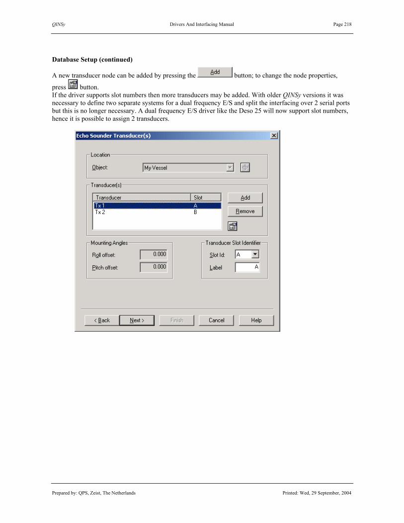
QINSy Drivers And Interfacing Manual Page 218
Prepared by: QPS, Zeist, The Netherlands Printed: Wed, 29 September, 2004
Database Setup (continued)
A new transducer node can be added by pressing the button; to change the node properties,
press button. If the driver supports slot numbers then more transducers may be added. With older QINSy versions it was necessary to define two separate systems for a dual frequency E/S and split the interfacing over 2 serial ports but this is no longer necessary. A dual frequency E/S driver like the Deso 25 will now support slot numbers, hence it is possible to assign 2 transducers.

QINSy Drivers And Interfacing Manual Page 219
Prepared by: QPS, Zeist, The Netherlands Printed: Wed, 29 September, 2004
Water Depth Reference. Important is whether or not transducer depth has been entered into the echosounder instrument, hence depth measured is below transducer or water level (reference point). QPS recommend setting the echosounder up so that depth output is from transducer (i.e. no transducer depth entered in instrument), as draft can change and QINSy assumes the vessel reference point at (0,0,0). Stabilization. Some echosounder are directly interfaced to a motion or attitude measurement system. The depth these echosounders output to QINSy are then already compensated for by motion. Select the appropriate options if depth is compensated for by E/S. Uncheck all options if E/S outputs uncorrected depths. Propagation Velocity. Water velocity is normally entered on the echosounder instrument, hence depth output is always corrected. In this case, set the QINSy velocity fields on echosounder parameters page the same, otherwise depth is divided by “Used Velocity” and then multiplied by “Calibrated Velocity”. Depth units. Select the units of the observation as output by the E/S. Most E/S output in meters but some model are known to output in US survey Feet. Important: Propagation velocities must be entered in the same unit as is selected here. So if units are set to feet, then velocities must also be entered in feet. See for more information the QINSy DB Setup Help Topics or the QINSy Knowledge Base.

QINSy Drivers And Interfacing Manual Page 220
Prepared by: QPS, Zeist, The Netherlands Printed: Wed, 29 September, 2004
3.7.1 Annotation Drivers Input / Output: Input (two-way) Driver class type: Terminated <CR> | <LF> | “*” Executable name: DrvAnnotate.exe Drivers.io options: ODOM | DESO25 | NMEA | SIMRAD Last modified: 2003-March-10 KLEIN2000 | KLEIN595 | TEXTOUT | KNUDSEN HF | KNUDSEN LF
Driver Description
Driver for decoding data messages from echosounders, outputting depth sensor data in Atlas Deso 15/20/25, Odom Echotrac, Simrad ASCII, Knudsen PKEL or NMEA format, or for decoding data messages from side-scan sonars Klein 595 and Klein 2000. The “Text Out” option of the annotation driver does not expect any input data. Driver can also send annotation messages (Fix Marks, SOL / EOL Info, Fix Event Info, etc.) to the sensor. Driver with user-interface, so settings can be changed online, by clicking on system button on taskbar.
The format of the annotation output string can be selected online, under Settings – Annotation. By default, this is the same format as for decoding data. There are also possibilities to send direct annotation messages. All user selections are saved to registry and restored the next time an annotation driver with the same system name (as defined in DB Setup) is started. The driver window displays the user selections. Notice that decoded values are not shown in the driver’s display. Decoded depth and altimeter readings can be seen using a Observation Physics Display.
Format Description
See for the various input data formats, the Format Description paragraph under the appropriate driver.
Interfacing Notes
It is important that the wiring of the cable between the echosounder and the COM port is bi-directional, i.e. allows two-way data transfer, so that the QINSy driver can send the annotation telegrams, if selected.

QINSy Drivers And Interfacing Manual Page 221
Prepared by: QPS, Zeist, The Netherlands Printed: Wed, 29 September, 2004
Database Setup
See description under “ECHOSOUNDER SYSTEM DRIVERS”. Be sure to select the driver according to the input format. The annotation format can be changed online.
Annotation Output
Use Settings – Annotation to select the annotation format and output data content. Use Options – Direct Annotation to send a fix mark and/or annotation comment directly to the echosounder or side-scan sonar. Use Context Sensitive Help in the Annotation Dialog to get more information about each specific item.
Advanced Annotation
With the Deso 25 and Odom Echotrac annotation formats, some advanced settings are available.

QINSy Drivers And Interfacing Manual Page 222
Prepared by: QPS, Zeist, The Netherlands Printed: Wed, 29 September, 2004
Advanced Annotation (continued)
Deso 25 (EM, TX) For the Deso 25, this is automatic start and stop of paper feed when starting and stopping a recording session. After EOL, paper feed will continue for some seconds, and after this delay, an additional paper feed is given. The chart speed can also be corrected (when paper is feeding), using the present vessel speed over ground. Note. Be aware that the Deso will interprete a small speed value as a stop paper feed command. Hence, when the vessel is stationary, testing these advanced annotation options will only result in some paper feed at EOL. Odom Echotrac (STX | NO STX) For the Odom Echotrac, advanced annotation options are to correct the echosounder system time, or to set the echosounder chart speed, using the vessel speed over ground. See annotation format descriptions below.
Annotation Output Formats
The annotation formats that are presently available are shown above. See also the appropriate input drivers. Deso 25 (EM, TX) Deso 25 annotation strings may contain up to 50 characters. Each message is ended with an EOB, End of Block, i.e. a ‘*’ character followed by <CR><LF>. Event Marker: EMn<CR><LF>
Field Format Description Values, Range, Units 1 EM event marker identifier “EM” 2 n event marker line type 0 = no line, 1 = dashed line
2 = dotted-dashed, 3 = solid 3 <CR><LF> termination characters <CR><LF> (0D Hex, 0A Hex)
User-Definable Text Message: TXccc---ccc<CR><LF>
Field Format Description Values, Range, Units 1 TX annotation string identifier “TX” 2 ccc---ccc user-definable text string handled as ordinary text 3 <CR><LF> termination characters <CR><LF> (0D Hex, 0A Hex)
Vessel Speed: VS+xx.xx_m/s<CR><LF>
Field Format Description Values, Range, Units 1 VS vessel speed identifier “VS” 2 +xx.xx_m/s signed speed over ground meters per second 3 <CR><LF> termination characters <CR><LF> (0D Hex, 0A Hex)
Deso 25 Example time and fix number sent to Deso 25, with a solid line as event marker TXUTC 15:36:55 Fix# 101<CR><LF>EM3<CR><LF>*<CR><LF>

QINSy Drivers And Interfacing Manual Page 223
Prepared by: QPS, Zeist, The Netherlands Printed: Wed, 29 September, 2004
Annotation Output Formats (continued)
Odom Echotrac (No STX) Odom Echotrac (STX) Odom annotation strings may contain up to 80 characters per line (42 characters for earlier models). With newer Echotrac sounders, it is no longer necessary to wait for the STX response byte before sending new annotation data. In such a case, the “No STX” option can be selected. For earlier models, select “STX”. Annotation Response: STX (Control B) Hex 02 Event Line (Fix Mark): ACK (Control F) Hex 06 Event Annotation (Start): SOH (Control A) Hex 01 Event Annotation (End): EOT (Control D) Hex 04 Multiple Line Annotation (New Line): CR (Control M) Hex 0D External Control of Unit Parameters: DLE (Control P) Hex 10 Parameter Transfer Protocol String: __nn_xxxx<CR><LF>
Field Format Description Values, Range, Units 1 __ start characters two spaces “ “ (32 Hex) 2 nn parameter number 1 - 21 3 _ separation character one space “ “ (32 Hex) 4 xxxx new parameter value 0 - 9999 5 <CR><LF> termination characters <CR><LF> (0D Hex, 0A Hex)
# Parameter Description Range Units 1 08 velocity 1370 - 1700 m/s 2 09 hours 0 - 23 hours 3 10 minutes 0 - 59 minutes 4 14 chart speed 8 - 1200 0.01 m/s
Simrad ($INATS) NMEA ($INATS) Simrad annotation is the same as NMEA annotation. At present, the checksum field is always added. Annotation Text String $--ATS,ccc---ccc*hh<CR><LF>
Field Format Description Values, Range, Units 1 $--ATS message type identifier “$INATS”(“--“ can be anything) 2 ccc---ccc text string handled as ordinary ASCII string 3 *hh checksum standard NMEA checksum field 4 <CR><LF> termination characters <CR><LF> (0D Hex, 0A Hex)

QINSy Drivers And Interfacing Manual Page 224
Prepared by: QPS, Zeist, The Netherlands Printed: Wed, 29 September, 2004
Annotation Output Formats (continued)
Klein 595 (EN, IN) Klein annotation strings may contain an annotation field up to 80 ASCII characters. The first N*16 characters in the field are broken down into N 16 character lines and are annotated on the sonar on receipt of the <CR>. Fix Event Annotation String <LF>enccc---ccc<CR>
Field Format Description Values, Range, Units 1 <LF> start character <LF> (0A Hex) 2 e mark line identifier “E” is mark line, “I” is no mark line 3 n number of annotation lines 1 - 5 4 ccc---ccc annotation field text string broken into N 16 character lines 5 <CR> termination character <CR> (0D Hex)
Update Vessel Speed <LF>S_vv.v<CR>
Field Format Description Values, Range, Units 1 <LF> start character <LF> (0A Hex) 2 S vessel speed update identifier “S” (53 Hex) 3 _ space character “ “ (20 Hex) 4 vv.v vessel speed value knots to tenths 5 <CR> termination character <CR> (0D Hex)
Klein 2000 ($PKLA) The QINSy driver treats Klein 2000 annotation strings the same way as Klein 595 annotation strings. Fix Event Annotation String $PKLA,EV,ccc---ccc*hh<CR><LF>
Field Format Description Values, Range, Units 1 $PKLA Klein Associates identifier “$PKLA” 2 EV message type identifier “EV” or “TE” 3 ccc---ccc text string handled as ordinary ASCII string 4 *hh checksum standard NMEA checksum field 5 <CR><LF> termination characters <CR><LF> (0D Hex, 0A Hex)

QINSy Drivers And Interfacing Manual Page 225
Prepared by: QPS, Zeist, The Netherlands Printed: Wed, 29 September, 2004
Annotation Output Formats (continued)
Knudsen ($PKEL02) Knudsen ($PKEL03) Knudsen 320 echosounder annotation strings may contain annotation field of maximal 68 ASCII characters. Event Marker with External Annotation Only $PKEL02,ccc---ccc<CR><LF> Event Marker with Internal and External Annotation $PKEL03,ccc---ccc<CR><LF>
Field Format Description Values, Range, Units 1 $PKEL Knudsen Engineering Limited “$PKEL” 2 nn message type identifier “02” or “03” to trigger event mark 3 ccc---ccc text string handled as ordinary ASCII string 4 <CR><LF> termination characters <CR><LF> (0D Hex, 0A Hex)
Set Speed of Sound in Echosounder $PKEL13,xxxx<CR><LF>
Field Format Description Values, Range, Units 1 $PKEL Knudsen Engineering Limited “$PKEL” 2 nn message type identifier “13” for speed of sound update 3 xxxx speed of sound in water 1300-1700 m/s or 4265-5577 ft/s 4 <CR><LF> termination characters <CR><LF> (0D Hex, 0A Hex)
Text Out EG&G Text Out Text annotation strings do not start with a header field, but are always ended by <CR><LF>. Text Out annotation strings are truncated to 256 characters. EG&G Text Out strings are truncated to 22 characters. Annotation Text String ccc---ccc<CR><LF>
Field Format Description Values, Range, Units 1 ccc---ccc text string handled as ordinary ASCII string 2 <CR><LF> termination characters <CR><LF> (0D Hex, 0A Hex)

QINSy Drivers And Interfacing Manual Page 226
Prepared by: QPS, Zeist, The Netherlands Printed: Wed, 29 September, 2004
Annotation Output Formats (continued)
EPC (EVENT, MES) EPC GSP-1086 annotation strings are truncated to 35 characters. Commands end with <CR> and/or <LF>. Event Marker: EVENT_DASHED<CR><LF>
Field Format Description Values, Range, Units 1 EVENT print and set event type “EVENT” or “EVE” 2 _ space character “ “ (20 Hex) 3 DASHED line type “DASHED” 4 <CR><LF> termination characters <CR><LF> (0D Hex, 0A Hex)
Annotation Text Message: MES_ccc---ccc<CR><LF>
Field Format Description Values, Range, Units 1 MES print annotation message “MES” or “MESSAGE” 2 _ space character “ “ (20 Hex) 3 ccc---ccc text string should not begin with number 4 <CR><LF> termination characters <CR><LF> (0D Hex, 0A Hex)
ESP ($@01) There is a separate ESP annotation driver which outputs quite long annotation strings. This driver’s ESP annotation strings are always truncated to 35 characters. Strings always start with the sequence “$@01”. Annotation Text String $@01ccc---ccc <CR><LF>
Field Format Description Values, Range, Units 1 $ start character “$” (24 Hex) 2 @ annotation channel A, B, C or @ (all channels) 3 0 start position 0 - 255 4 1 paper direction 0 = right to left, 1 = guess what 5 ccc---ccc text string handled as ordinary ASCII string 6 <CR><LF> termination characters <CR><LF> (0D Hex, 0A Hex)

QINSy Drivers And Interfacing Manual Page 227
Prepared by: QPS, Zeist, The Netherlands Printed: Wed, 29 September, 2004
3.7.2 Deso 15 / 20 / 25 Echosounder Input / Output: Input Driver class type: Terminated <LF> Executable name: DrvAtlasDeso.exe Drivers.io options: Last modified: 6 June 2003
Driver Description
Driver for decoding a depth sensor message (D# and BC-message) from an Atlas Deso 15 / 20 or 25 echosounder. The driver will decode the depth reading (in meters) and the bottom condition (as quality indicator) when available. The D#-message contains data for transducer A or B. The user can specify which transducer(s) will be used, by selecting the appropriate slot in DB Setup. The driver will detect how the data string is terminated (<*> or <CR><LF>). The driver will also detect which Deso format needs to be decoded.
Format Description
The Atlas Deso 15 data message consists of four lines of fixed length, which are separated by <CR><LF>. When “Auto Output” has been selected, a data string is output upon completion of each sounding. “DA/DB” depth presented is in metres, 00000.00 - 00650.00 m, or feet, 00000.00 - 02130.00 ft. “BC” bottom condition is a parameteric strength signal, NOT identical to the Atlas Deso 25 values. (1) The extension 'dB' is kept for compatibility reasons, although the value itself is NOT measured in dB. Range of the value is 00.0 - 99.9. DAxxxxx.x_m<CR><LF> (where ‘_’ is a space) DBxxxxx.x_m<CR><LF> (where ‘_’ is a space) BCxx.xdB<CR><LF> (no space before unit) *<CR><LF> The Atlas Deso 20 data message consists of one line per transducer, separated by <CR><LF> DAxxxxx.x_m<CR><LF> (where ‘_’ is a space) DBxxxxx.x_m<CR><LF> (where ‘_’ is a space) Item Format Description Values or Units
1 D# depth channel "DA" for 1 or "DB" for 2 2 Xxxxx.x_m echosounder depth reading m 3 BC bottom condition 4 Xx.xdB parametric strength signal (1) 5 * end of block * 6 <CR><LF> line termination characters carriage return | line feed
(continued on next page)

QINSy Drivers And Interfacing Manual Page 228
Prepared by: QPS, Zeist, The Netherlands Printed: Wed, 29 September, 2004
The following message was also encountered as output from Deso 20. (The driver will detect this format when it is encountered). 000000ssDDDD<CR><LF> Where ss is the channel/slot number, and DDDD is the depth reading in cm’s. The depth reading will be ignored when DDDD data is zero. Format Example data of this rare format: 000000010289 (will be decoded as 2.89m depth, for Slot A) 000000110259 (will be decoded as 2.59m depth, for Slot B) 000000010289 000000110260 000000010293 000000110261
Database Setup
See description under “ECHOSOUNDER SYSTEM DRIVERS”. Select in Db Setup driver "Deso 15/20/25" and select which channel (‘A’ or ‘B’) needs to be decoded. To decode the data with channel ‘01’ use slot ‘A’, to decode the data with ‘channel’ 11 use ‘B’.

QINSy Drivers And Interfacing Manual Page 229
Prepared by: QPS, Zeist, The Netherlands Printed: Wed, 29 September, 2004
3.7.3 Deso 25 (With Annotation) Input / Output: Input (two-way) Driver class type: Terminated <LF> | “*” Executable name: DrvAnnotate.exe Drivers.io options: DESO25 Last modified: 2000-Dec-01
Driver Description
Driver for decoding depth sensor messages (D# and BC-message) from Atlas Deso 15 / 20/ 25 echosounders. The driver will decode the depth reading (in meters), as well as the bottom condition (as quality indicator), if present. The D#-message contains depth readings for transducer A or B, corresponding to channel 1 or 2. Driver can also send annotation messages (Fix Marks, SOL / EOL Info, Fix Event Info) to the echosounder. Driver with user-interface, so settings can be changed online, by clicking on system button on taskbar.
The format of the annotation output string can be selected online, under Settings – Annotation. By default, this is the same format as for decoding data. There is also a possibility to send a direct annotation string. All user selections are saved to Windows registry and restored the next time an annotation driver with the same system name (as defined in DB Setup) is started. The driver window displays the user selections. Notice that decoded values are not shown in the driver’s display. Decoded depth and bottom condition readings can be seen using a Observation Physics Display.
Format Description
See the Format Description of the “Atlas Deso 15 / 25 (Depth Channel A or B) Echosounder. Driver will automatically determine the type of input data format, Deso 15 / 25 or Deso 20.
Annotation Output
See the Annotation Output paragraph for the “Annotation Drivers”.
Database Setup
See description under “ECHOSOUNDER SYSTEM DRIVERS”.

QINSy Drivers And Interfacing Manual Page 230
Prepared by: QPS, Zeist, The Netherlands Printed: Wed, 29 September, 2004
3.7.4 Bathy UK94 Pressure Sensor (Depth)
3.7.5 Bathy UK94 Pressure Sensor (Altitude) Input / Output: Input Driver class type: Terminated <LF> Executable name: DrvBathyUK94.exe Drivers.io options: OI Last modified: 1997-Oct-20
Driver Description
Driver for decoding depth sensor message from a Bathy UK94 bathymetric system. The BathyUK94 driver can decode the depth reading or the altitude reading (both of them in meters). The BathyUK driver handles automatically the Standard UK90 format, the Alternate UK90 format or the MB1000/HB200 format.
Format Description
The Alternate UK90 Format is given by Dxxxx.xx Axx.xx Txx Pxxxx Vxxxxx dxxxxx Hxx<CR><LF> The Standard UK90 Format (twice the Altitude field) is given by Dxxxx.xx Axx.xx Axx.xx Txx Pxxxx Vxxxxx dxxxxx Hxx<CR><LF>
Item Format Description Values or Units 1 Dxxxx.xx depth meters 2 Axx.xx altitude meters 3 Txx temperature degrees centigrade 4 Pxxxx atmospheric pressure OR entered by the system operator,
OR measured by surface barometer 5 Vxxxxx velocity of sound in water 6 Dxxxxx relative density of seawater 7 Hxx height of unit above seawater 8 <CR><LF> termination characters carriage return + line feed
Some example Standard UK90 format data strings are given by D 000.48 A00.37 A00.37 T12 P1010 V14849 d10274 H02 D 000.48 A00.38 A00.38 T12 P1010 V14849 d10274 H02 D 000.47 A00.37 A00.37 T12 P1010 V14849 d10274 H02 D 000.47 A00.38 A00.38 T12 P1010 V14849 d10274 H02 Where, in last message, depth is 0.47 m and altitude is 0.38 m. Notes. (1) Fields have fixed widths, all fields separated by spaces; string ends with <CR><LF> (2) The MB1000/HB200 Format is similar, except for depth to 999.99 m, so Dxxx.xx (3) Typical system output interface parameters are 4800,8,2,N (9600 baud is optional)
Database Setup
See description under “ECHOSOUNDER SYSTEM DRIVERS”.

QINSy Drivers And Interfacing Manual Page 231
Prepared by: QPS, Zeist, The Netherlands Printed: Wed, 29 September, 2004
3.7.6 EG&G Sonar System (Depth) Input / Output: Input Driver class type: Terminated <CR> Executable name: DrvEchoSounder.exe Drivers.io options: none Last modified: 1999-Nov-03
Driver Description
Driver for decoding depth from a EG&G side scan sonar system. The driver will automatically determine the format of the input data string. The depth output from an EG&G sonar is just the first return of a sonar ping.
Format Description
Each EG&G depth message has a fixed length of 11 bytes, including termination characters <CR><LF>. RRR DDD.D<CR><LF> 12345678901 where RRR is range in meters and DDD.D is depth in meters. The two values are separated by a space.
Format Example 100 025.0<CR><LF>
Decoding Notes
The range is copied to the quality indicator of the depth observation. Use “Observation Physics Display”.
Database Setup
See description under “ECHOSOUNDER SYSTEM DRIVERS”.

QINSy Drivers And Interfacing Manual Page 232
Prepared by: QPS, Zeist, The Netherlands Printed: Wed, 29 September, 2004
3.7.7 Elac LAZ 4400 Echosounder Input / Output: Input Driver class type: Terminated <CR> Executable name: DrvElacLAZ4400.exe Drivers.io options: N/A Last modified: 1999-Nov-23
Driver Description
Driver for decoding depth from an Elac LAZ 4400 echosounder. The driver will decode the depth reading in meters. The feet and fathoms fields are ignored.
Format Description
Each data message has a fixed length of 34 bytes. The datastring is terminated by <CR><LF>.
Item Format Description Values or Units 1 $SDDBK header - 2 xxxx.x feet value feet 3 f feet indicator - 4 yyyy.y meter value meter 5 M meter indicator - 6 zzzz.z fathom value fathom 7 F fathom indicator - 8 <CRLF> termination characters carriage return + line feed
Format Example $SDDBK,0027.2,f,0008.3,M,004.5,F<CRLF>
Database Setup
See description under “ECHOSOUNDER SYSTEM DRIVERS”.

QINSy Drivers And Interfacing Manual Page 233
Prepared by: QPS, Zeist, The Netherlands Printed: Wed, 29 September, 2004
3.7.8 Elac STG 721 Echosounder Input / Output: Input Driver class type: Terminated <CR> Executable name: DrvElacSTG721.exe Drivers.io options: LOW | HIGH Last modified: 1999-Oct-27
Driver Description
Driver for decoding depth from an Elac STG 721 echosounder. The driver will decode the depth reading (if not in meters – so feet or fathoms - it will be always converted to meters), as well as the status (as the quality indicator) in both LOW and HIGH frequency mode.
Format Description
Each data message has a fixed length of 11 bytes. The datastring is terminated by <CR><LF>.
Value Unit Frequency Overflow A m Low no B ft Low no C ftm Low no E m High no F ft High no G ftm High no I m Low yes J ft Low yes K ftm Low yes M m High yes N ft High yes O ftm High yes
Format Examples <LF>E000308@<CR><LF> <LF>A000321O<CR><LF> <LF>E000311@<CR><LF> <LF>A000321O<CR><LF>
Decoding Notes
The quality indicator of the depth observation will be 0 if no error occurred. In case of an error, the quality indicator of the depth observation will be 1.
Database Setup
See description under “ECHOSOUNDER SYSTEM DRIVERS”.

QINSy Drivers And Interfacing Manual Page 234
Prepared by: QPS, Zeist, The Netherlands Printed: Wed, 29 September, 2004
3.7.9 Kaijo Denki PS20R Echosounder Input / Output: Input Driver class type: Counted Executable name: DrvKaijoDenkiPS20R.exe Drivers.io options: none Last modified: 1997-Oct-06
Driver Description
Driver for decoding depth sensor message from the echosounder. The driver will decode the depth reading (value in centimetres converted meters), as well as the status (as the quality indicator).
Format Description
Each message is fixed in length. The message is NOT terminated by <CR><LF>. Format example: D1 Record mark : D2 Data byte length ( 2 bytes ) 0 D3 A D4 Counter data ( 4 bytes ) repetition "0000" to "FFFF" 0 D5 0 D6 D D7 9 D8 Record type ( 2 bytes ) 0 D9 0 D10 Depth data in cm ( 6 bytes ) 0 D11 0 D12 0 D13 2 D14 4 D15 8 D16 moving average frequency ( 2 bytes ) 0 D17 4 D18 Status 0 D19 2 D20 Checksum (Suplementary number of 2 from D2 to D18) C D21 D
Interfacing Notes
The default fequency for data is 10Hz at 9600 Baud, 2 stop bits, 8 data bits and no handshaking.
Database Setup
See description under “ECHOSOUNDER SYSTEM DRIVERS”.

QINSy Drivers And Interfacing Manual Page 235
Prepared by: QPS, Zeist, The Netherlands Printed: Wed, 29 September, 2004
3.7.10 Knudsen 320M (PKEL HF) (With Annotation)
3.7.11 Knudsen 320M (PKEL LF) (With Annotation)
Input / Output: Input (two-way) Driver class type: Terminated <LF> Executable name: DrvAnnotate.exe Drivers.io options: KNUDSEN | HF | LF Last modified: 2003-March-10
Driver Description
Driver for decoding water depths from a Knudsen 320M echosounder, providing a $PKEL telegram. The driver will decode the water depth reading (in meters). The driver can also output a NMEA annotation telegram. Driver with user-interface, so settings can be changed online, by clicking on system button on taskbar:
The driver window displays the user selections. Notice that decoded values are not shown in the display.
Format Description
$PKEL,nnn,hhmmss,LF,ll.ll,HF,hh.hh*hh<CR><LF>
Field Format Description Values, Range, Units 01 ‘$PKEL’ message type identifier Header 02 nnn Not used 03 hhmmss time Not used 04 ‘LF’ Low Frequency identifier 05 ll.ll Low Frequency water depth Meters 06 ‘HF’ High Frequency identifier 07 hh.hh High Frequency water depth Meters 04 *hh optional checksum XOR from “$” to “*” exclusive 05 <CR><LF> termination characters <CR><LF> (0D Hex, 0A Hex)

QINSy Drivers And Interfacing Manual Page 236
Prepared by: QPS, Zeist, The Netherlands Printed: Wed, 29 September, 2004
Example:
$PKEL,007,165809,LF,00.00,HF,02.55*20<CR><LF> $PKEL,007,165810,LF,00.00,HF,02.55*28<CR><LF> $PKEL,007,165811,LF,00.00,HF,02.55*29<CR><LF>
Interfacing Notes
It is important that the wiring of the cable between the echosounder and the COM port is bi-directional, i.e. allows two-way data transfer, so that the QINSy driver can send the annotation telegrams, if selected.
Annotation Output
See the Annotation Output paragraph for the “Annotation Drivers”.
Drivers.io Options
Command line parameter “KNUDSEN” will decode any $PKEL telegram. Parameter “HF” will decode the high frequency value, parameter “LF” will decode the low frequency.
Database Setup
See description under “ECHOSOUNDER SYSTEM DRIVERS”. Select the “Knudsen 320M (PKEL HF/LF) (With Annotation)” driver to decode any incoming $PKEL telegrams. Note. Presently only one frequency is allowed in the QINSy driver. Split input to decode multiple frequency.

QINSy Drivers And Interfacing Manual Page 237
Prepared by: QPS, Zeist, The Netherlands Printed: Wed, 29 September, 2004
3.7.12 Marimatech E-Sea Sound Echosounder Input / Output: Input Driver class type: Terminated <LF> Executable name: DrvESeaSound.exe Drivers.io options: LOW | HIGH Last modified: 2000-Jul-07
Driver Description
Driver for decoding depth from a Marimatech E-Sea Sound echosounder. The driver will decode the depth reading (if not in meters – so feet or fathoms - it will always be converted to meters) in both LOW and HIGH frequency mode. Whether or not the LOW or the HIGH frequency value comes first in the data message is not important for decoding the right value.
Format Description
Two types of data messages exist, which have a fixed length. The 1 Channel data message contains 22 characters. The 2 Channel data message takes 40 characters. Each message is terminated by <CR><LF>. 1 Channel data message: ERSF####,##UU,DDD,BB<CRLF> 2 Channel data message: ERSF####,##UU,DDD,BB,F####,##UU,DDD,BB<CRLF> Item Format Description Values or Units
1 E Identifier for Echo Format "E" 2 R Identifier for heave compensation "R" = Raw depth
"C" = Corrected depth 3 S Identifier for status "S" = Standby : Paper stop
"R" = Running : Paper on "M" = Marked depth "E" = Error (No depth)
4 F Identifier for frequency "H" = High frequency "L" = Low frequency
5 ####,## Depth in 0.01 units (2 decimals accuracy) 0043.60 6 UU Unit " m" = meter
"ft" = foot " F" = fathom
7 DDD Delay in milliseconds from Echosounder time to first character
546
8 BB Bottom amplitude strength 0-99 9 <CR><LF> termination characters carriage return | line feed
Format Example
1 Channel data message: ERSL0043.60 m,546,56<CR><LF> 2 Channel data message: ERSH0019.60 m,516,86,L0019.60 m,517,86<CR><LF>
Decoding Notes
The system update time will be corrected for the delay in milliseconds, which is present in the data messages.
Database Setup
See description under “ECHOSOUNDER SYSTEM DRIVERS”.

QINSy Drivers And Interfacing Manual Page 238
Prepared by: QPS, Zeist, The Netherlands Printed: Wed, 29 September, 2004
3.7.13 Odom Echotrac/Digitrace (High Freq | Low Freq | Single Freq)
3.7.14 Odom Echotrac (With Annotation and STX | no STX)
3.7.15 Raytheon (Single Frequency) Input / Output: Input (two-way) Driver class type: Terminated <CR> Executable name: DrvAnnotate.exe Drivers.io options: ODOM | S | H | L | U | STX Last modified: 2003-Jul-29
Driver Description
Driver for decoding depth sensor messages in Odom Echotrac/Digitrace formats. Both the standard output format and the dual bottom tracking output formats (single frequency and dual frequency) are supported. The driver will apply the default scale factors according to the resolution, or 0.01 for the Raytheon, but this scale factor can be changed online. Driver can also send annotation messages to the Odom echosounder. Driver with user-interface, so settings can be changed online, by clicking on system button on taskbar:
The format of the annotation output string can be selected online, under Settings – Annotation. By default, this is the same format as for decoding data. There is also a possibility to send a direct annotation string. All user selections are saved to Windows registry and restored the next time an annotation driver with the same system name (as defined in DB Setup) is started. The driver window displays the user selections. Notice that decoded values are not shown in the display.

QINSy Drivers And Interfacing Manual Page 239
Prepared by: QPS, Zeist, The Netherlands Printed: Wed, 29 September, 2004
Format Description
Standard Output FETECddddd<CR>
Field Format Description Values, Range, Units 01 space or “F” “F” indicates fix mark ignored 02 “ET” or “et” EchoTrac and resolution “ET” 1/10 feet, “et” 1/100 metres 03 space or “E” “E” indicates an error not decoded in case of “E” error 04 space or “C” “C” indicates heave compensated ignored 05 ddddd depth data 0 – 99999 06 <CR> termination character <CR> (0D Hex)
Dual Bottom Tracking Output – Single Frequency FETEH_ddddd<CR>
Field Format Description Values, Range, Units 01 space or “F” “F” indicates fix mark ignored 02 “ET” or “et” EchoTrac and resolution “ET” 1/10 feet, “et” 1/100 metres 03 space or “E” “E” indicates an error not decoded in case of “E” error 04 “H” or “L” frequency indicator “H” high, “L” low frequency 05 space always space (“C”?) ignored 06 ddddd depth data 0 – 99999 07 <CR> termination character <CR> (0D Hex)
Dual Bottom Tracking Output – Dual Frequency FETEB_ddddd<CR>
Field Format Description Values, Range, Units 01 space or “F” “F” indicates fix mark ignored 02 “ET” or “et” EchoTrac and resolution “ET” 1/10 feet, “et” 1/100 metres 03 space or “E” “E” indicates an error not decoded in case of “E” error 04 “B” frequency indicator “B” for dual frequency 05 space always space (“C”?) ignored 06 ddddd high frequency depth data 0 – 99999 07 space always space (“C”?) ignored 08 ddddd low frequency depth data 0 – 99999 09 <CR> termination character <CR> (0D Hex)
Note. The Digitrace formats only differ from the Echotrac formats in usage of “DT” instead of “ET”. ET -> units on echosounder are set to US Survey feet, et -> units to metres.
Annotation Output
See the Annotation Output paragraph for the “Annotation” drivers.
Drivers.io Options
Command line parameter “U” followed by a number will set a default scale factor.
Database Setup
See description under “ECHOSOUNDER SYSTEM DRIVERS”. Make sure that the output units are set correctly in DbSetup.

QINSy Drivers And Interfacing Manual Page 240
Prepared by: QPS, Zeist, The Netherlands Printed: Wed, 29 September, 2004
3.7.16 NMEA (DPT,DBT,DBS) (With Annotation)
3.7.17 Simrad EA-Series ASCII Telegram (With Annotation) Input / Output: Input (two-way) Driver class type: Terminated <LF> Executable name: DrvAnnotate.exe Drivers.io options: NMEA | SIMRAD Last modified: 2000-Oct-02
Driver Description
Driver for decoding water depths from an echosounder providing a NMEA DPT, DBT or DBS telegram, or from an echosouder outputtting a Simrad ping based ASCII telegram, such as a Simrad EA 400 system. The driver will decode the water depth reading (in meters) and the bottom condition (as quality indicator), if available in case of a Simrad ASCII telegram. The driver can also output a NMEA annotation telegram. Driver with user-interface, so settings can be changed online, by clicking on system button on taskbar:
The driver window displays the user selections. Notice that decoded values are not shown in the display.
Format Description
NMEA DPT (Depth) $--DPT,x.x,y.y*hh<CR><LF>
Field Format Description Values, Range, Units 01 $--DPT message type identifier -- can be anything 02 x.x water depth relative to transducer meters 03 y.y offset of the measuring transducer meters 04 *hh optional checksum XOR from “$” to “*” exclusive 05 <CR><LF> termination characters <CR><LF> (0D Hex, 0A Hex)

QINSy Drivers And Interfacing Manual Page 241
Prepared by: QPS, Zeist, The Netherlands Printed: Wed, 29 September, 2004
Format Description (continued)
NMEA DBT (Depth Below Transducer) $--DBT,x.x,f,y.y,M,z.z,F*hh<CR><LF>
Field Format Description Values, Range, Units 01 $--DPT message type identifier -- can be anything 02 x.x, f water depth relative to transducer feet 03 y.y, M water depth relative to transducer meters 04 z.z, F water depth relative to transducer fathoms 05 *hh optional checksum XOR from “$” to “*” exclusive 06 <CR><LF> termination characters <CR><LF> (0D Hex, 0A Hex)
NMEA DBT (Depth Below Surface) $--DBS,x.x,f,y.y,M,z.z,F*hh<CR><LF>
Field Format Description Values, Range, Units 01 $--DPT message type identifier -- can be anything 02 x.x, f depth referenced to water surface feet 03 y.y, M depth referenced to water surface meters 04 z.z, F depth referenced to water surface fathoms 05 *hh optional checksum XOR from “$” to “*” exclusive 06 <CR><LF> termination characters <CR><LF> (0D Hex, 0A Hex)
Simrad Ping Based ASCII Telegram D#,hhmmss.ss,xxxx.xx,zzz,TDN,ABS<CR><LF>
Field Format Description Values, Range, Units 01 D header (always) “D” 02 # channel number 1, 2, 3 03 hhmmss.ss time of transmission computer’s present time 04 xxxx.xx depth from transducer incl. draft meters 05 zzz bottom surface backscattering dB 06 TDN transducer number (never used in EA 400) 07 ABS athwarthship bottom slope degrees (not used in EA 400) 08 <CR><LF> termination characters <CR><LF> (0D Hex, 0A Hex)
Annotation Output Telegram $--ATS,ccc---ccc<CR><LF>
Field Format Description Values, Range, Units 01 $--ATS message type identifier -- can be anything (“IN”) 02 ccc---ccc text string handled as ordinary text 03 <CR><LF> termination characters <CR><LF> (0D Hex, 0A Hex)
Decoding Notes
Driver will decode the x.x field from a NMEA DPT telegram or the y.y field from a NMEA DBT or DBS telegram. Signal quality indicator is always 1 for a water depth decoded from a valid NMEA telegram. Driver will decode the xxxx.xx field from the Simrad ASCII telegrams. The zzz field is decoded as signal quality indicator. The time field in the Simrad ASCII telegram is disregarded by the QINSy driver.

QINSy Drivers And Interfacing Manual Page 242
Prepared by: QPS, Zeist, The Netherlands Printed: Wed, 29 September, 2004
System Configuration
The NMEA telegrams can only provide depth information from one channel. With the Simrad EA 400 echosounder system, which channel is used, is selected in the depth output dialog box, whereas the telegram type to be transmitted (DPT, DBT, DBS, Simrad, Atlas Deso 25) is selected in the same dialog box. For the Simrad ASCII output telegram, one telegram is exported from each echosounder channel (limited to 3).
Interfacing Notes
It is important that the wiring of the cable between the echosounder and the COM port is bi-directional, i.e. allows two-way data transfer, so that the QINSy driver can send the annotation telegrams, if selected.
Annotation Output
See the Annotation Output paragraph for the “Annotation Drivers”.
Drivers.io Options
Command line parameter “NMEA” will decode any DPT, DBT and/or DBS telegram. Parameter “SIMRAD” will decode the Simrad ASCII telegram that starts with the “D#” combination for the selected channel.
Database Setup
See description under “ECHOSOUNDER SYSTEM DRIVERS”. Select the “NMEA (DPT,DBT,DBS) (With Annotation)” driver to decode any incoming NMEA DPT, DBT and/or DBS telegrams. Select the “Simrad ASCII (With Annotation)” to decode a so-called Simrad ping based ASCII telegram for a certain channel.

QINSy Drivers And Interfacing Manual Page 243
Prepared by: QPS, Zeist, The Netherlands Printed: Wed, 29 September, 2004
3.7.18 Simrad EA-Series ASCII Telegram
3.7.19 Simrad EA-Series ASCII Telegram (With UTC) Input / Output: Input Driver class type: Terminated <LF> Executable name: DrvSimradEA50x.exe Drivers.io options: PPS Last modified: 23 December 2003
Driver Description
Driver for decoding the Simrad ASCII telegram. This (depth) telegram is used by a number of Simrad EA series echosounder systems – e.g. EA400, EA500, EA501P, EA600. The driver will decode the depth reading (in meters), as well as the bottom surface backscattering strength (as quality indicator). The D#-message contains data for transducer 1, 2 or 3. The user can specify which transducer will be used (‘1’, ‘2’, 3’’), or ignore the transducer number by selecting the appropriate slot (‘Any’) in DB Setup. The Simrad (EA500, EA501P) device can also output a motion sensor message (MS-message), containing roll, pitch and heave. This driver can decode this message. The Simrad EA501P device can also output a NMEA Depth message ($SDDBS). This driver will not decode this message.
Format Description
Each Simrad EA500 / EA501P message is variable in length; but fields are separated by a comma delimiter. The datastring is terminated by <CR><CR><LF>. Item Format Description Values or Units
1 D# Header "D1" or "D2" or "D3" 2 HHMMSSss time of depth reading ss = hundredth of second 3 x.x echosounder depth reading m 4 x bottom surface backscattering strength dB 5 n transducer number 6 x athwartships bottom slope ° 7 <CR><CR><LF> termination characters 2 × carriage return | 1 × line feed
Format Examples D1,12275838, 10.60, -5, 1, 0<CR><CR><LF> D1,12280010, 10.80, -8, 1, 0<CR><CR><LF> D1,12280181, 10.60, -6, 1, 0<CR><CR><LF>
Decoding Notes
The quality indicator of the depth observation will be the bottom surface backscattering strength value. Notice that time, transducer number and athwartships bottom slope are not used by QINSy. For time-tagging purposes the time from the Depth message will be used if the driver “Simrad EA-Series ASCII Telegram (With UTC)” has been chosen. If the other driver (without the UTC) has been chosen, local computer time (or PPS if it is connected to QINSy) will be used for time-tagging.
Database Setup
See description under “ECHOSOUNDER SYSTEM DRIVERS”.

QINSy Drivers And Interfacing Manual Page 244
Prepared by: QPS, Zeist, The Netherlands Printed: Wed, 29 September, 2004
3.7.20 Simrad EA-Series (Socket)
3.7.21 Simrad EA-Series (Socket) (With UTC) Input / Output: Input Driver class type: UDP/IP Client Executable name: DrvSimradEAxxxSocket.exe Drivers.io options: PPS Last modified: 2003-May-16
Driver Description
Driver for decoding the Simrad Ping Based Binary Datagram from a Simrad EA400, EA500 or EA600 echosounder via a network connection. The driver is also capable of decoding the Sidescan Echogram (binary) datagram. Refer to Sidescan Systems chapter for more details.
Format Description – Simrad Ping Based Binary Datagram
The driver will decode the depth reading (in meters), as well as the reflectivity (as quality indicator). The D#-message contains data for channel #. The user may specify which channel will be decoded, by setting up the channel parameters DB Setup. The datagram has a fixed length of 28 bytes, the first part is ASCII, the second part is binary. D#,HHMMSShh,Depth,Reflectivity,Transducer no,Athwartships angle Where: D# 2 chars header, # indicates the channel number <ASCII> , 1 char separator <ASCII> HHMMSShh 8 bytes -- time when ping is transmitted <ASCII> , 1 char separator <ASCII> Depth 4 bytes floating point number <Binary> Reflectivity 4 bytes floating point number <Binary> Transducer no 4 bytes integral number <Binary> Athwartships angle 4 bytes floating point number <Binary>
Format Examples D1,08143838,...Aq...........D2,08143838,..%?"f.......... D1,08143861,...AQ.l.........D2,08143861,..%?.G.......... D1,08143885,.r.A............D2,08143885,..%?............ D1,08143914,.O.AK...........D2,08143914,..%?............ D1,08143936,.G.A............D2,08143936,..%?............ D1,08143959,...A./..........D2,08143959,..%?|........... D1,08143981,A>.A.3..........D2,08143981,.A ?............
Decoding Notes
The quality indicator of the depth observation will be the reflectivity value (in case of D#-message) which can be monitored with an Observation Physics Display. For time-tagging purposes the time from the Depth message will be used if the driver “Simrad EA-Series (Socket) Channel # (With UTC)” has been chosen. If the other drivers (without the UTC) have been chosen, local computer time (or PPS if it is connected to QINSy) will be used for time-tagging. Notice that all other fields (like transducer number, athwart ships angle) are not used by QINSy.

QINSy Drivers And Interfacing Manual Page 245
Prepared by: QPS, Zeist, The Netherlands Printed: Wed, 29 September, 2004
Database Setup
See description under “ECHOSOUNDER SYSTEM DRIVERS”. Further, the (Network UDP) Port number must be the same as the Remote Computer Port number, where the Simrad Echosounder is sending the data onto the network.

QINSy Drivers And Interfacing Manual Page 246
Prepared by: QPS, Zeist, The Netherlands Printed: Wed, 29 September, 2004
During testing the following settings have been used for the network interface of the QINSy PC.

QINSy Drivers And Interfacing Manual Page 247
Prepared by: QPS, Zeist, The Netherlands Printed: Wed, 29 September, 2004
On the Simrad Echosounder you must also define, besides the Port number, the IP Address of the Remote Computer. It is recommended to use a mask for the last field of the address.

QINSy Drivers And Interfacing Manual Page 248
Prepared by: QPS, Zeist, The Netherlands Printed: Wed, 29 September, 2004
3.7.22 Sweep Depth (Imtech DMS 3500) Input / Output: Input Driver class type: UDP/IP Client Executable name: DrvDraughtSocket.exe Drivers.io options: none Last modified: 2003-Dec-10
Driver Description
Driver for decoding the depth from a sweep system. See for more information Miscellaneous driver ‘Draught Measurement System (Imtech DMS 3500).

QINSy Drivers And Interfacing Manual Page 249
Prepared by: QPS, Zeist, The Netherlands Printed: Wed, 29 September, 2004
3.8 MULTI-TRANSDUCER ECHOSOUNDER DRIVERS
Database Setup
First define and select the “Object” on which the multi-transducer system is located. Select item “Systems” and define a new “Multi-transducer Echosounder”. Select the appropriate driver and interface parameters. Be sure to select a baud rate that is high enough to transfer all the data. Press the “Next” button to complete the setup. Select the object on which the transducers are located. Enter multi-transducer parameters. Press the “Next” button to add the tranducer nodes and their slot numbers. Press “Finish” to save the system.

QINSy Drivers And Interfacing Manual Page 250
Prepared by: QPS, Zeist, The Netherlands Printed: Wed, 29 September, 2004
(this page intentionally left blank)

QINSy Drivers And Interfacing Manual Page 251
Prepared by: QPS, Zeist, The Netherlands Printed: Wed, 29 September, 2004
3.8.1 Navitronic (DPP 2000) Input / Output: Input Driver class type: Terminated <LF> Executable name: DrvNavitronic.exe Drivers.io options: none Last modified: 2002-06-14
Driver Description
Driver to decode the Navitronic Multi-channel Echosounder. The system consist of a DPP 2000 Controller, which handles up to ten MCS 2000 Units. Each unit can have 6 channels (read: transducer). The DPP 2000 outputs for each channel the range measurement from the transducer head to the riverbed or from water level to the riverbed. This is a setting on the DPP Controller! The DPP Controller may operate in Full Sync or in Group Sync mode. The driver will autodetect the mode.
Format Description
Full sync.mode (all channels transmit at the same time) = 203 Characters $F11112222------nnnnq---qllllcl Where: $F 2 characters, Start sign indicating Full sync. mode
1111 4 characters, depth in cm for channel #1 2222 4 characters, depth in cm for channel #2 --- etc… nnnn 4 characters, depth in cm for channel #39 q---q 39 times 1 character, Quality number for each channel llll 4 characters, Latency in msec cl 2 characters, Carriage Return and Linefeed
Group sync.mode (all channels #1 for each group, then all channels #2, and so on) = 223 Characters $G11112222------nnnnq---qllll---llllcl Where: $G 2 characters, Start sign indicating Group sync. mode
1111 4 characters, depth in cm for channel #1 2222 4 characters, depth in cm for channel #2 --- etc… nnnn 4 characters, depth in cm for channel #39 q---q 39 times 1 character, Quality number for each channel llll---llll 6 times 4 characters, Latency in msec for each group
cl 2 characters, Carriage Return and Linefeed

QINSy Drivers And Interfacing Manual Page 252
Prepared by: QPS, Zeist, The Netherlands Printed: Wed, 29 September, 2004
Format Example Full Sync Mode $F 182 173 165 321 376 173 153 185 0 0 0 0999989980000 212 $F 182 173 165 321 365 173 153 185 0 0 0 0899889980000 212 $F 182 173 167 321 365 173 153 185 0 0 0 0999999980000 207 $F 182 173 165 321 371 173 153 185 0 0 0 0989899980000 203
Format Example Group Sync Mode $G 562 547 547 532 532 532 517 503 489 489 476 476999999999999 180 181 182 183 184 479 $G 542 557 547 532 532 522 517 503 489 489 476 476999999999999 180 181 182 183 184 479 $G 522 537 547 532 532 512 517 503 489 489 476 476999999999999 180 181 182 183 184 479 $G 512 547 547 532 532 522 507 503 489 489 576 476999999999999 180 181 181 181 184 479
Decoding Notes
At this moment only 12 channels (hard-coded) are decoded. The Qaulity Indicator can be interpreted as a figure between o and 9, 9 stands for best quality, 0 for poorest.
Interfacing Notes
Only a one-way interfacing cable is required for this driver.
Database Setup
See description under MULTI-TRANSDUCER ECHOSOUNDER SYSTEM DRIVERS. Additionally all the transducer nodes must be defined as variable nodes on the vessel. These can be assigned to the system on the last page of the multi-transducer system wizard. The slot numbers are the locations of the depth soundings in the string. Normally the portside most transducer is number 1.
Drivers.io Options
None.

QINSy Drivers And Interfacing Manual Page 253
Prepared by: QPS, Zeist, The Netherlands Printed: Wed, 29 September, 2004
3.8.2 STN Atlas Bomasweep Input / Output: Input (two-way) Driver class type: Terminated <LF> Executable name: DrvAtlasBomasweep.exe Drivers.io options: none Last modified: 2001-05-08
Driver Description
Driver for the Atlas Bomasweep. This sensor consists of a number (49) of separate sensors, each giving a range measurement from the transducer to the riverbed.
Format Description
The composite system sends a number of strings. The first six characters denote the type of string. The most important is the SZ7202 string, which contains the raw depth measurements. The depths are decoded up to 5 decimal places, units are centimeters. A depth quality is also included (1 = valid, 0 = invalid). Some other data strings are: ST0015: number of transducers; PA0020: start and end depth; SZ0014: sound velocity.
Format Example SZ7202 18205767 00000000000 000000000 000000 000000 000520 0000 0001 001 00 00000 034 000 02472 1 02450 1 02427 1 02401 1 02373 1 02344 1 02311 1 02278 1 02243 1 02207 1 02170 1 00554 1 00555 1 00556 1 00557 1 01980 1 01942 1 01904 1 01868 1 01834 1 01801 1 01769 1 01738 1 01710 1 01685 1 01661 1 01640 1 01621 1 01606 1 01593 1 01584 1 01577 1 01572 1 01572 1 01574 1 01580 1 01589 1 01600 1 01614 1 01631 1 01651 1 01674 1 01700 1 01726 1 01756 1 01788 1 01822 1 01857 1 01892 1
Decoding Notes
Only the 4 above mentioned data strings (SZ7202, ST0015, PA0020, SZ0014) are decoded. A quality indicator is decoded from the incoming data. It can be interpreted as a “Brightness Test” flag, 1 stands for a valid beam, 0 for an invalid beam.
Interfacing Notes
A two-way interfacing cable is required for this driver. At startup, the driver sends the last used start/end depth and sound velocity to the unit. The user may enter the required depths and speed of sound in the GUI and send them to the unit.
Database Setup
See description under MULTI-TRANSDUCER ECHOSOUNDER SYSTEM DRIVERS. Additionally all the transducer nodes must be defined as variable nodes on the vessel. These can be assigned to the system on the last page of the multi-transducer system wizard. The slot numbers are the locations of the depth soundings in the string. Normally the portside most transducer is number 1.
Drivers.io Options
None.

QINSy Drivers And Interfacing Manual Page 254
Prepared by: QPS, Zeist, The Netherlands Printed: Wed, 29 September, 2004
(This page intentionally left blank)

QINSy Drivers And Interfacing Manual Page 255
Prepared by: QPS, Zeist, The Netherlands Printed: Wed, 29 September, 2004
3.9 MULTIBEAM ECHOSOUNDER DRIVERS
Database Setup
First define and select the “Object” on which the multibeam transducer is located. Select item “Systems” and define a new “Multibeam echosounder”. Select the appropriate driver and interface parameters. Be sure to select a baud rate that is high enough to transfer all the data. Press the “Next” button to complete the setup. Select object and node for the transducer. Enter multibeam parameters. Press “Finish” to save the system.

QINSy Drivers And Interfacing Manual Page 256
Prepared by: QPS, Zeist, The Netherlands Printed: Wed, 29 September, 2004
Database Setup (continued)
A new transducer node can be added by pressing the button; to change its properties, press button.
Note 1. Dual head multibeam echosounders are treated by QINSy as two separate MBE systems, each with its own transducer node, node offsets and mounting angles. Roll offset values usually will have opposite signs. Note 2. In case of Reson Seabat network drivers, the Seabat UTC synchroniser driver has to be defined too. Note 3. The number of beams is very important. Be sure that it corresponds to the output of the MBE unit. Note 4. A sound velocity profile can be entered in DB Setup under “Edit – New – Velocity Profile”. When online in the Controller, select “Settings – Echosounders – Refraction” to determine which profile to use. Note 5. Mounting angles result of calibration. Those from the Patch Test utility or Validator can be entered directly. Press the next button to go to the Dynamic Correction pages.

QINSy Drivers And Interfacing Manual Page 257
Prepared by: QPS, Zeist, The Netherlands Printed: Wed, 29 September, 2004
Database Setup (continued)
Sound Velocity Here you can select if you want to correct for wrong sound velocity. This is only applicable to Kongsberg Simrad Multibeam systems, primarily EM3000, For any other brand this correction is not used. The multibeamer can apply a correction to the beam- and tilt angles if the sound velocity differs between what was entered as fixed value inside the multibeam system and what is actually measured with a sound velocity probe at the head. Selected can be ‘none’, in that case no correction are required. In order to activate this option you should define an Underwater Sensor - Sound Velocity observation first. To define an underwater sensor system refer to respective chapter. Dynamic Alignment – Heading/Pitch/Roll The Heading/Roll/Pitch options can be used if the multibeam transducer is mounted on a rotating frame. If the multibeam transducer has a fixed mounting, as with most survey vessels , this is not relevant and you should leave these options unchecked. If the transducer is mounted on a turning or tilting frame, check the required rotation axis/axes and assign the angle observation of that particular angle. Note that the angle observation must be defined first in order to select it here. Only observations of type “Angle” and with the “At Node” corresponding to the Multibeam Transducer Node are displayed here.

QINSy Drivers And Interfacing Manual Page 258
Prepared by: QPS, Zeist, The Netherlands Printed: Wed, 29 September, 2004
Database Setup (continued)
Dynamic Alignment – Dynamic Offsets Sometimes a multibeam transducer is placed on a retractable frame or pole. This is often the case with hull-mounted sonar’s. If the range of the transducer displacement is interfaced into QINSy then the multibeam results can be compensated for the fact that the transducer offsets change. QINSy supports a transducer displacement in only one direction, by default the vertical direction. It is however possible to define the direction in which the pole moves, this is useful when the pole is not mounted exactly vertical into the reference frame of the vessel. If this is the case then a transducer displacement not only causes the Z local coordinate to change but it also effects the transducers’ X and Y local coordinates. The system that measures the length of the transducer pole must be interfaced with a Surface Navigation system driver to QINSy. Generally this is a custom made driver, for example the WAGO driver. It is also possible to select a manual driver; you can then enter the length of the transducer pole yourself. About setting up the Surface Navigation System: First select the correct system, then an observation with type “Range” must be defined. Make sure to select the correct unit / C-O and / or scale factor. -Define the Location/At Node identical to the node that was selected for the multibeam system. If the node is not identical to that of the multibeam system then the range observation can never be selected in the multibeam system settings! -Define the To Node as the local offset of the transducer when it is fully lowered. If the pole is mounted straight down in the vessel frame then make the X/Y coordinates identical for both nodes and the To Node’s Z coordinate smaller than the At Node. With these setting QINSy will apply the shift as purely vertical. If the At- and To Nodes have different X/Y coordinates then the shift is considered to be in a non-vertical direction. The transducer will move on a straight line that intersects with the two nodes. Important. QINSy will assume that the transducer is located in the at-node if the observed range observation is zero. If the range equals the distance between the at- and to-node then QINSy assumes that the transducer is located in the to-node. For more information on how to setup a range observation refer to the chapter “Surface Navigation Systems”. See for more information the QINSy DB Setup Help Topics or the QINSy Knowledge Base.

QINSy Drivers And Interfacing Manual Page 259
Prepared by: QPS, Zeist, The Netherlands Printed: Wed, 29 September, 2004
Mechanical Profiler Systems
QINSy considers profiler systems as multibeam echosounder systems with different ping times for each beam (data point), instead of one ping time for all beams. Processing of the data points is therefore similar. Important note. It is important to realize that a profiler scan contains data points which have been collected during some period of time that can last seconds. In addition, the data strings are quite long and take some time to be transferred to the QINSy computer. Add some time for pre/post scans and calculations in the profiler system, and it will take seconds after the start of a scan, before the QINSy driver will receive and decode the data string and the MultiBeamer module can start processing a profiler scan. Before September 2004, there was a limitation to the number of positions (10, registry setting, see remark *) and the number of attitude values (200, fixed) that are available in the MultiBeamer for interpolation. From September 2004 on, these values have been changed to 20 and 500, respectively. For fast updating positioning systems or gyro and/or MRU systems, the number of positions or attitude values can possibly be not enough to cover the time period needed to compute and correct all the scan data points. It is therefore recommended to use update rates of 1 Hz for positioning systems and maximal 10-20 Hz for attitude systems. This will also improve positioning by the Adjustment/PositionFilter modules. *) [HKEY_CURRENT_USER\Software\QPS\QINSy\7.0\Core\MultiBeamer\Settings] "MaxPosUpdates" The number of positions must be enough to be able to compute the oldest data point in a profiler data string. For example, if the triggering system for the computation updates 2 times a second and the profiler data string contains 6 seconds of data points (calculated by the driver) and is sent 1 second after it has been compiled by the profiler (system latency), interpolation will require 2·(6+1) + 1 = 15 positions.
Pipe and Cable Tracker Systems
QINSy considers pipe- or cable-tracker systems as multibeam echosounder systems with just one beam (data point) in dX-dY-dZ format, where dY is often 0. Processing of the data points is therefore similar.

QINSy Drivers And Interfacing Manual Page 260
Prepared by: QPS, Zeist, The Netherlands Printed: Wed, 29 September, 2004
3.9.1 Aran Rut Bar Input / Output: Input Driver class type: Counted Executable name: DrvAranRutBar.exe Drivers.io options: none Last modified: 2000-10-30
Driver Description
Driver for the Aran Rutbar sensor. This sensor is used on the Automatic Road Analyzer (ARAN) for profile measurements of roads. The sensor uses a proprietary format that may not be reproduced here. The driver is configured as a multibeam system and creates XYZ multibeam observations. The number of beams is taken from the calibration data.
Decoding Notes
The observations are checked for too short to long values, and corrected for the measurement window base. Optionally the value from the calibration sensor can be used as a scale-factor to correct the observations. The decoded Quality Indicator (QI) can be interpreted as a figure with a range between 0 and 3: QI Beam Status 1 Interpolated (=best quality) 2 Invalid 3 Bad Observation
System Configuration
The Rutbar is connected to a Central Data Acquisition Computer (CDAC) which configures the Rutbar. The commands from the CDAC and the replies from the Rutbar are both available to QINSy on the same pin.
Database Setup
See description under MULTIBEAM ECHOSOUNDER SYSTEM DRIVERS. The maximum number of beams received from the Rutbar is 39.
Drivers.io Options
None

QINSy Drivers And Interfacing Manual Page 261
Prepared by: QPS, Zeist, The Netherlands Printed: Wed, 29 September, 2004
3.9.2 L3 Communications Seabeam 1180 / 1885 Input / Output: Input (Network) Driver class type: TCP Client Executable name: DrvSeabeamSocket.exe Drivers.io options: None Last modified: 2000-Jul-07
Driver Description
Driver for L3 Communication 1180 en 1885 multibeam echosounders using a network connection to the L3 Communications supplied HydroStar software. The driver will decode the data and present it to rest of the system as mechanical profiler data. The reason for this is the timing mechanism that is being used to transmit the acoustic energy. Acoustic energy is being transmitted for small groups of beams (i.e. 3 beams) which causes different ping times for each group of beams. The driver uses a network connection with the L3 supplied HydroStar software to obtain the multibeam data. The system time on the computer running the HydroStar software needs to be synchronized to the system time of the computer running QINSy. This may be accomplished by synchronizing both computers to the same time frame (i.e. a PPS interface on both computers) or by running the QINSy and the HydroStar software on the same computer.
Format Description
See the L3 issued document with the title “Data Exchange Format (XSE)”. The driver was developed using revision 1.6 of this document.
Decoding Notes
The timetag from the data packets is used. Therefore it is required to synchronize the times of the QINSy and the HydroStar system to UTC using an external timeframe (i.e. PPS interface from a GPS receiver). The packets that are being decoded are: - Multibeam General Group - Multibeam Traveltime Group - Multibeam Delay Group - Multibeam Angle Group The decoded Quality Indicator (QI) can be interpreted as a figure with a value between 1 and 8, 1 stands for best quality, 8 for worst quality.
System Configuration
See description below.
Database Setup
See description on next page and under “MULTIBEAM ECHOSOUNDER SYSTEM DRIVERS”.
Controller Setup
When online, select the "Echosounder ..." option from the "Settings” menu to define the positioning of the echosounder transducer node, as well as the online blocking and filtering of the multibeam echosounder data. Use a Raw Multibeam Display to show raw data and a Swath System Display to show the corrected scans.

QINSy Drivers And Interfacing Manual Page 262
Prepared by: QPS, Zeist, The Netherlands Printed: Wed, 29 September, 2004
Seabeam IP Number & Port Number Configuration From the HydroStar software the data packets are send over a network link. This requires all computers involved to run the TCP/IP protocol on their network cards. As with any network configuration, the IP numbers for all computers involved should be unique. The following screen capture shows an installation on which the HydroStar software is running on the computer with IP address 10.0.0.7 and is listening on port 3400 (= default HydroStar port).

QINSy Drivers And Interfacing Manual Page 263
Prepared by: QPS, Zeist, The Netherlands Printed: Wed, 29 September, 2004
Changing the Hydrostar Software priority setting To allow accurate time tagging of the sensors in QINSy the priority of certain drivers is elevated above the normal priority setting. Since the HydroStar software functions as an intermediate driver between the L3 Seabeam unit and QINSy its priority also needs to be increased. Because QINSy only increases the priority of its own drivers the user has to manually increase the priority of the HydroStar software. This has to be repeated every time the user starts the HydroStar software. However this procedure only needs to be executed when the HydroStar software and QINSy are running on the same computer. If the HydroStar software is running on a separate computer (which needs to be synchronised to the computer running QINSy) this procedure is not required. To increase the priority the user has to start the Task Manager by right clicking in the taskbar. After the Task Manager has started the second tab sheet called ‘Processes’ shows all the running processes. The user should search for a process called “hydrostar.exe”. Once found, he/she should right click on the process to change its priority setting to “High” (see also screen capture below). This makes sure that Hydrostar software receives enough CPU time to perform accurate time tagging.

QINSy Drivers And Interfacing Manual Page 264
Prepared by: QPS, Zeist, The Netherlands Printed: Wed, 29 September, 2004
3.9.3 Marimatech E-Sea Swath 501 (5 Channel echosounder) Input / Output: Input (two-way) Driver class type: Terminated Executable name: DrvESeaSwath501.exe Drivers.io options: Last modified: 2000-Mar-31
Driver Description
Driver for Marimatech E-Sea Swath 501 5 channel echosounder. The echosounder is seen as a mechanic profiler because of the delays for each of the five channels. The echosounder unit is interrogated for the sound velocity (CS<CRLF>) at startup and when resetting the I/O.
Format Description
<F1><F2><F3><F4>111111,ddd,ss,222222,ddd,ss,333333,ddd,ss,444444,ddd,ss,555555,ddd,ss<CRLF> Field Format Description Example ------------------------------------------------------------------------------------------------------------------------ 1 <F1> See below (*1) N/A 2 <F2> See below (*2) N/A 3 <F3> See below (*3) N/A 4 <F4> Reserved x 5 111111 Distance to bottom in us 79452 6 ddd Delay in msec (*4) 88 7 ss Bottom ampl.strength (*5) 65 8-19 4 more channels (2-5) 20 <CRLF> Carriage return linefeed *1 Can be C (Corrected for roll / pitch and heave) or R (Raw data) *2 Can be M (Request marker info from computer) or x (No marker info) *3 Can be 1-5 (Printer on, channel selected for continuous printout) or x (Printer off) *4 Delay in msec between sending the first byte of the depth string
and transmitting by the corresponding channel *5 Bottom amplitude strength (relative units in the range of 0-99) Example data: Rxxx72120,88,65,79452,169,56,76640,255,56,79026,337,59,82720,422,43 Sound velocity data, as returned on interrogation, is according to the following format: CSVVVV<units><CRLF>, for example CS1485m/s where CS is a header, VVVV is the sound velocity, and <units> can be "m/s", "ft/s", "f/s".
Decoding Notes
No Quality Indicators (QI) are available. QI will always be set to 3.
Database Setup
See description under “MULTIBEAM ECHOSOUNDER SYSTEM DRIVERS”.
QINSy Drivers And Interfacing Manual Page 265
Prepared by: QPS, Zeist, The Netherlands Printed: Wed, 29 September, 2004
3.9.4 Odom Echoscan
3.9.5 Odom Echoscan XTF Input / Output: Input Driver class type: Counted Executable name: DrvOdomechoscan.exe Drivers.io options: RAW | NOCS Last modified: 2003-Aug-12
Driver Description
Driver for Odom Echoscan Multibeam Echosounders using a serial cable connection. The Odom Echoscan is a 30 beam Echosounder which uses so-called physical beamforming. In fact it can be seen as a multi transducer echosounder with all it’s transducers integrated in a single hull. The XTF version will store the raw XTF data records in the QINSy database. Such a database can afterwards be used to export the XTF records to a separate file. However, using this option will create much larger db’s.
Format Description
Serial Output Strings Serial output data rate from the ECHOSCAN SPU is 19.2 KBaud, updating as fast as 16 times / second (depending upon the Range selected). Output strings are ASCII binary and described as follows: Data Description Sync Header Four, 8-bit bytes (FFh, FFh, 00h, 00h) identifying the beginning of the output string Packet Type (10 or 01) Two 8-bit bytes (00h, 01h) identify the ECHOSCAN binary output *1 Year (0-99), Month (1-12), Day (1-31), Hour (0-23), Minute (0-59), Second (0-59) Six, 8-bit bytes - Year (00h-63h), Month (01h-0Ch), Day (01h-1Fh), Hour (00h-17h), Minute (00h-3Bh), Second (00h-3Bh) Sound Velocity (1200-1700 m/s) One 16-bit word (Example: 04h B0h - 06h A4h) as set by the operator on the LCDU Latency (0-1000 ms) One 16-bit word (Example: 00h 00h - 03h E8h) indicating the time lapsed between the sonar ping to the start of the fourth byte in the output string Sampling Rate (HZ) One 16-bit word representing the digitizing frequency Range Samples / Beam Quality Individual range readings (in No. of samples)*1 Range = Range Samples (Sound Velocity) / Sample Rate 2 Checksum One 16-bit word, unsigned sum of all 8-bit bytes excluding the sync byte. *1 The ECHOSCAN string contains 30, 16-bit ranges for a total of 80 bytes and a transmission time of 42 ms. Beam directions are in 3° increments, across Port (Beam 1) to Starboard (Beam 30). Beams 15 and 16 are each 1.5° off nadir. The most significant 14 bits of each range represent the round trip travel time in samples. The 15th and 16th bits (least significant) indicate beam quality, i.e., 00b = bad, 01b = low signal strength, 10b = out of sequence, and 11b = good. [source Odom echoscan manual]

QINSy Drivers And Interfacing Manual Page 266
Prepared by: QPS, Zeist, The Netherlands Printed: Wed, 29 September, 2004
Decoding Notes
- Timetag from data packets is not used, instead the time of arrival of the first string is used in combination with the latency provided in the output message. The latency is typically identical to the ping interval. - Decoded ranges are considered to be from one common acoustic centre in the middle of the transducer hull. - The decoded Quality Indicator (QI) can be interpreted as a figure with the following possible values: QI Beam Status 0 Bad (= worst) 1 Low Signal Strength 2 Out of Sequence 3 Good (=best)
Database Setup
See description under “MULTIBEAM ECHOSOUNDER SYSTEM DRIVERS”. Refer to Odom documentation for information about the acoustic centre of the transducer.
Controller Setup
When online, select the "Echosounder..." option from the "Settings” menu to define the positioning of the echosounder transducer node, as well as the online blocking and filtering of the multibeam echosounder data. Use a Raw Multibeam Display to show raw data and a Swath System Display to show the corrected scans. To exclude invalid beam data from the result dtm’s you can flag the beam based on the beam quality indicator value. Set for example the Echosounder settings “Exclude Data when – Quality outside” range from 3 to 3 to block beams that do not have a Quality of “Good”.
Drivers.io Options
Command line parameter “NOCS” can be used to skip checksum test. “RAW” will store the XTF records.

QINSy Drivers And Interfacing Manual Page 267
Prepared by: QPS, Zeist, The Netherlands Printed: Wed, 29 September, 2004
3.9.6 Reson Seabat 81xx/900x (Serial) [XTF] Input / Output: Input Driver class type: Counted Executable name: DrvSeabatSerial.exe Drivers.io options: RAW | NOCS Last modified: 1999-Dec-10
Driver Description
Driver for Reson Seabat 81xx & 900x series Multibeam Echosounders using a serial cable connection. Driver will automatically detect the input format, but will only decode R_THETA or RI_THETA packets. The XTF version will store the raw XTF data records in the QINSy database. Such a database can afterwards be used to export the XTF records to a separate file. However, using this option will create much larger db’s.
Format Description
See Reson Seabat manuals.
Decoding Notes
The timetag from the data packets is not used, instead the time of arrival of the first string is used in combination with the latency provided in the output message. The decoded Quality Indicator (QI) can be interpreted as two flags: - Brightness Flag (0 = invalid, 1 = valid) - Colinearity flag (0 = invalid, 1 = valid)
Database Setup
See description under “MULTIBEAM ECHOSOUNDER SYSTEM DRIVERS”.
Drivers.io Options
Command line parameter “NOCS” can be used to skip checksum test. “RAW” will store the XTF records.
Seabat 81xx/900x Offsets
Drawings that show the acoustic centres for the SeaBat 900x series (left) and SeaBat 8101 (right) systems
Source: Reson Inc website (http://www.reson.com)

QINSy Drivers And Interfacing Manual Page 268
Prepared by: QPS, Zeist, The Netherlands Printed: Wed, 29 September, 2004
3.9.7 Reson Seabat 81xx/900x (Network) [XTF] Input / Output: Input (Network) Driver class type: UDP/IP Client Executable name: DrvSeabatSocket.exe Drivers.io options: RAW | NOCS Last modified: 1999-Dec-10
Driver Description
Driver for Reson Seabat 81xx & 900x series Multibeam Echosounders using a network connection. The driver will automatically detect the input format, but will only decode R_THETA or RI_THETA packets. The XTF version will store the raw XTF data records in the QINSy database. Such a database can afterwards be used to export the XTF records to a separate file. However, using this option will create much larger db’s.
Format Description
See Reson Seabat manuals.
Decoding Notes
The timetag from the data packets is used (if it is not zero) if the Reson Seabat driver is a network driver. Therefore it is highly recommended to synchronize the times of the QINSy and Seabat systems by adding the output driver “Seabat 8000 Series UTC Synchroniser” to the database. If the QINSy online setup includes a PPS system, then the timetag will be truly UTC. See description under “OUTPUT SYSTEM DRIVERS”. The decoded Quality Indicator (QI) can be interpreted as two flags: -Brightness Flag (0 = invalid, 1 = valid) -Colinearity flag (0 = invalid, 1 = valid)
System Configuration
See description below.
Database Setup
See description on next page and under “MULTIBEAM ECHOSOUNDER SYSTEM DRIVERS”.
Controller Setup
When online, select the "Echosounder..." option from the "Settings” menu to define the positioning of the echosounder transducer node, as well as the online blocking and filtering of the multibeam echosounder data. Use a Raw Multibeam Display to show raw data and a Swath System Display to show the corrected scans.
Drivers.io Options
Command line parameter “NOCS” can be used to skip checksum test. “RAW” will store the XTF records.
Seabat IP Number Configuration
From the Reson Seabat units some, or all, data types can be sent over a network link. These data are of a broadcast type and require the receiving computers to run the TCP/IP protocol on their network cards. As with any network configuration, the IP numbers of both the computer and the Seabat unit should be unique. (continued on next page)

QINSy Drivers And Interfacing Manual Page 269
Prepared by: QPS, Zeist, The Netherlands Printed: Wed, 29 September, 2004
Seabat IP Number Configuration (continued)
The 9000 series sonar will send its bathymetry data over the serial ports only. If the sidescan option is enabled, this data will be made available over the network connection only. QPS has not yet encountered a 9000 series sonar with sidescan option, so unit is assumed to work identical to the 8100 series sonar. The description above applies for the 8101 series sonar. Bathymetry is available on the serial port only and sidescan data is only available on the network port. The later models of the 8100 series, like the 8125 and 8111, have the option to send the bathymetry data over the network connection too. This is necessary, as the huge amount of data cannot be processed over the serial connection, even at 115200 baud. For the network connection the following IP addresses have been used successfully. (1) On a dual head 8125 installation, the two sonar processors had IP addresses 010.000.001.001 and 010.000.001.002. The computer was set to IP address 010.000.001.003. Although many more combination will operate, this is a proven combination. (2) On a 8101 installation using sidescan the settings for local can be 010.000.001.001 and extern 010.000.001.003 and the port set to 1028. Be sure to set the sidescan option working in Menu 6 , recommended is to use the RMS option. However, many more combinations might be working as well. In the ‘byte’ screen of the Seabat unit the IP addresses can be set. To enter the ‘byte’ screen click on the green square in the top left corner of the display. This square can be red if there is an error in the setup. Set the IP address for ‘local’ to the IP address of the Seabat unit. The ‘extern’ IP address can be set to the address of the computer you want to receive the data on. This setting seems to be ignored, as there is a ‘subnet’ mask to be set. This defines which range of IP numbers will receive the data. In our example setting above we could set a subnet mask of 255.255.255.0. This will only allow computers in the IP range of 10.0.1.0 to 10.0.1.255 to receive the data. The port number needs to be defined and has to be unique on the network as well. This is what can be compared as the serial port number in serial communications. Port numbering is related to IP numbering and workable values in our example are 1028 and 1020. The difference in port numbers has to be 8 or more. In Db Setup one only has define the port number at which the unit broadcasts as driver parameter. The IP numbering is obsolete and not visible anymore. Older versions of QINSy will get prompted to enter an IP address. This address should be the address of the Seabat processor.

QINSy Drivers And Interfacing Manual Page 270
Prepared by: QPS, Zeist, The Netherlands Printed: Wed, 29 September, 2004
3.9.8 Reson Seabat 7K (Network) Input / Output: Input (Network) Driver class type: TCP Client Executable name: DrvSeabat7K.exe Drivers.io options: none Last modified: 2003-Dec-31
Driver Description
Driver that decodes bathymetry, sidescan and snippet data (snippet not supported yet) from a Reson Seabat 7K series Multibeam Echosounder using a network connection. The driver will automatically connect to the multibeam system over the network interface. The driver will request only the records that it needs in order to fulfil its interfacing task; this keeps the network traffic as low as possible. The driver can also be used to send commands (e.g. start pinging/stop pinging) to the Seabat 7K. Commands are initiated from another driver (to be implemented). The Seabat 7K processor can process data from multiple sonar and /or bathymetry Seabat systems. This driver will always select the first available multibeam system that is reported by the processor. XTF is not yet supported.
Format Description
The Driver requests various record types from the Seabat 7K. This depends on what type of data must be decoded: Data type: Required 7K records Bathymetry 7000 (Ping Header), 7004 (Beam Angles), 7006 (Ranges) Sidescan 7000 (Ping Header), 7007 (Sidescan Image) Snippets 7000 (Ping Header), 7004 (Beam Angles), 7006 (Ranges), 7008 (Beam Data) Note: snippet decoding is not supported yet The driver uses the 7500 (Remote Command) record to send commands to the Seabat 7K. For more details on these records please refer to the Reson Seabat 7K Interface Control Document.
Decoding Notes
The time tag from the 7000 record’s RECORD_FRAME is used as the ping observation time. Therefore it is crucial for proper operation that both Seabat 7K unit and QINSy are UTC synchronised (PPS). Currently it is not possible to synchronise the Seabat 7K with the “Seabat 8000 Series UTC Synchroniser” driver and therefore should it be synchronised to UTC (PPS) autonomously. -The decoded Quality Indicator (QI) can be interpreted as a figure with a range between 0 and 15. Zero depicts bad quality while 15 stands for best quality.
System Configuration
See description below.
Database Setup
See description on next page and under “MULTIBEAM ECHOSOUNDER SYSTEM DRIVERS”.

QINSy Drivers And Interfacing Manual Page 271
Prepared by: QPS, Zeist, The Netherlands Printed: Wed, 29 September, 2004
Controller Setup
When online, select the "Echosounder..." option from the "Settings” menu to define the positioning of the echosounder transducer node, as well as the online blocking and filtering of the multibeam echosounder data. Use a Raw Multibeam Display to show raw data and a Swath System Display to show the corrected scans.
Drivers.io Options
None.
Seabat IP Number Configuration
As with any network configuration, the IP numbers of both the computer and the Seabat unit should be unique. Since the connection type is TCP it obligatory to enter the port number and the IP address of the Seabat 7K processor. DbSetup: -Port number must always be 7000. The Seabat 7K processor will always listen to connection requests on this port number. -IP address is the address of the Seabat 7K processor.
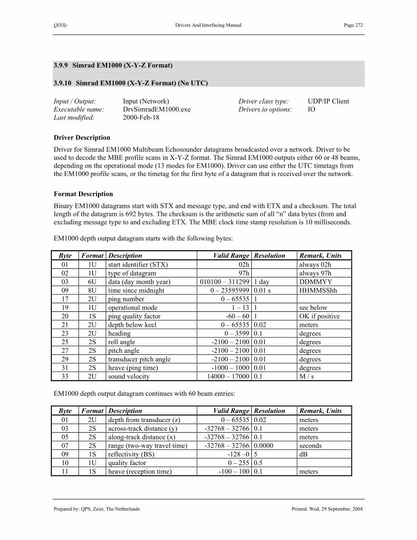
QINSy Drivers And Interfacing Manual Page 272
Prepared by: QPS, Zeist, The Netherlands Printed: Wed, 29 September, 2004
3.9.9 Simrad EM1000 (X-Y-Z Format)
3.9.10 Simrad EM1000 (X-Y-Z Format) (No UTC) Input / Output: Input (Network) Driver class type: UDP/IP Client Executable name: DrvSimradEM1000.exe Drivers.io options: IO Last modified: 2000-Feb-18
Driver Description
Driver for Simrad EM1000 Multibeam Echosounder datagrams broadcasted over a network. Driver to be used to decode the MBE profile scans in X-Y-Z format. The Simrad EM1000 outputs either 60 or 48 beams, depending on the operational mode (13 modes for EM1000). Driver can use either the UTC timetags from the EM1000 profile scans, or the timetag for the first byte of a datagram that is received over the network.
Format Description
Binary EM1000 datagrams start with STX and message type, and end with ETX and a checksum. The total length of the datagram is 692 bytes. The checksum is the arithmetic sum of all “n” data bytes (from and excluding message type to and excluding ETX. The MBE clock time stamp resolution is 10 milliseconds. EM1000 depth output datagram starts with the following bytes:
Byte Format Description Valid Range Resolution Remark, Units 01 1U start identifier (STX) 02h always 02h 02 1U type of datagram 97h always 97h 03 6U data (day month year) 010100 – 311299 1 day DDMMYY 09 8U time since midnight 0 – 23595999 0.01 s HHMMSShh 17 2U ping number 0 – 65535 1 19 1U operational mode 1 – 13 1 see below 20 1S ping quality factor -60 – 60 1 OK if positive 21 2U depth below keel 0 – 65535 0.02 meters 23 2U heading 0 – 3599 0.1 degrees 25 2S roll angle -2100 – 2100 0.01 degrees 27 2S pitch angle -2100 – 2100 0.01 degrees 29 2S transducer pitch angle -2100 – 2100 0.01 degrees 31 2S heave (ping time) -1000 – 1000 0.01 degrees 33 2U sound velocity 14000 – 17000 0.1 M / s
EM1000 depth output datagram continues with 60 beam entries:
Byte Format Description Valid Range Resolution Remark, Units 01 2U depth from transducer (z) 0 – 65535 0.02 meters 03 2S across-track distance (y) -32768 – 32766 0.1 meters 05 2S along-track distance (x) -32768 – 32766 0.1 meters 07 2S range (two-way travel time) -32768 – 32766 0.0000 seconds 09 1S reflectivity (BS) -128 –0 5 dB 10 1U quality factor 0 – 255 0.5 11 1S heave (reception time) -100 – 100 0.1 meters

QINSy Drivers And Interfacing Manual Page 273
Prepared by: QPS, Zeist, The Netherlands Printed: Wed, 29 September, 2004
EM1000 depth output datagram ends with the following bytes:
Byte Format Description Valid Range Resolution Remark, Units 01 1U end identifier (ETX) 03h always 03h 02 1U checksum (LSB) 03 1U checksum (MSB)
The operational modes are 1 = 60°, 2 = 120°, 3 = 150°, 4 = channel, 5 = 150°, 6 = 140°, 7 = 128°, 8 = 120°, 9 = 104°, 10 = 88°, 11 = 70°, 12 = port bank, 13 = starboard bank. Modes 1-3 have equiangle beam spacing, the rest equidistant. Mode 1 and 11 have a pulse length of 2 ms and 48 beams per ping, mode 2 and modes 8-10 0.7 ms and 48 beams per ping with interlacing, the other modes 0.2 ms and 60 beams with interlacing. See for more information on how these values can differ for the various EM1000 modes and how these values should be interpreted, the Kongsberg Simrad – Simrad EM Series P2317 – Datagram Formats.
Decoding Notes
Only time, depth, across-track distance, along-track distance, reflectivity and quality factor are decoded. -The decoded Quality Indicator (QI) is actually the number of beams that is used for bottom tracking within a range of 0 and 60. It is unknown which value is worst or which is best.
System Configuration
The unix workstation with Simrad software running on it, must send the data to QINSy through one of its Ethernet LAN ports. The workstation contains four LAN interfaces, LAN2, LAN3, LAN4 and LAN5. From these four interfaces, LAN4 is used to communicate with the X terminal(s) so this port can’t be used to output data. Any other available port can be used. The workstation starts a so-called “data distribution” program for every LAN port; these programs handle the internal and external Ethernet communication of the workstation. The “data distribution” programs read an ASCII configuration that contains which type of datagrams are to be sent and where to send them; the files are stored in the rt user’s home directory. A config file has a user definable file name; therefore an environment variable must be set for each “data distribution” program. The following steps must be taken to add an output:
1) Determine which Ethernet LAN interface can be used. Either use a free port (in this case a config file should be added) or select a used port (in this case a config file must be modified and a HUB should be used to split the cables) If a used port is selected go to 3)
2) Add a MODULE_ADDRESESS environment variable to the start-up script named “start_data_distrib” (location unknown). for example: LAN3.addresses
3) Change or add a data distribution config file for the selected port The config file name should consist of the environmental var. with the host name added, for example LAN3.addresses.EM121A. File must be placed in rt user’s home directory. Look at the other config files for info regarding the structure of these files. A line must be added at the bottom of the config file according the following format: <module name> <IP Address> <IP port nr> [<datagram1> <datagram2> …] for example: QINSy 128.160.50.130 2010 0x97

QINSy Drivers And Interfacing Manual Page 274
Prepared by: QPS, Zeist, The Netherlands Printed: Wed, 29 September, 2004
Notes: -This will enable the sending of a depth(0x97) telegram to the QINSy PC which has an IP number of 128.160.50.130 and multibeam driver listens on port 2010. -Use only spaces , no TABS allowed!! -This chapter is provided for background information, QPS recommends that only qualified Kongsberg Simrad Engineers modify the workstation set-up. -For more information contact your local Kongsberg Simrad Agent
Database Setup
See description under “MULTIBEAM ECHOSOUNDER SYSTEM DRIVERS”, except that the driver can only be used on a network, so instead of entering serial port parameters, the port number has to be entered.
Controller Setup
When online, select the "Echosounder ..." option from the "Settings” menu to define the positioning of the echosounder transducer node, as well as the online blocking and filtering of the multibeam echosounder data. Use a Raw Multibeam Display to show raw data and a Swath System Display to show the corrected scans.
Drivers.io Options
Command line parameter “IO” means that the first byte is time stamped, so that the QINSy time is used.

QINSy Drivers And Interfacing Manual Page 275
Prepared by: QPS, Zeist, The Netherlands Printed: Wed, 29 September, 2004
3.9.11 Simrad EM300x (R-Theta Format)
3.9.12 Simrad EM3000 (X-Y-Z Format)
3.9.13 Simrad EM3000D Head II (X-Y-Z Format)
3.9.14 Simrad EM3000D Head II (R-Theta Format)
3.9.15 Simrad EM3000 (R-Theta Format / D)
3.9.16 Simrad EM3000D Head II (R-Theta Fmt / D)
3.9.17 Simrad EM300x XTF (R-Theta Format)
3.9.18 Simrad EM300x XTF (X-Y-Z Format)
3.9.19 Simrad EM1002 (R-Theta Format) Input / Output: Input (Network) Driver class type: UDP/UP Client Executable name: DrvSimradEM3000.exe Drivers.io options: 0 | 1 | 2 | DII | RAW EM1002 Last modified: 2004-Feb-24
Driver Description
Driver for Simrad EM3002 / EM3000(D) / EM1002 Multibeam Echosounder datagrams broadcasted over a network. Driver to be used to decode either the XYZ position of the footprints (X-Y-Z Format) or the raw range and angle (R-Theta Format) from either D,F or f datagram. The Simrad EM3000(D) has 127 (2 x 127) beams, but only valid beams will be broadcasted. The EM3002 (an improved EM3000) will have maximum 254 beams. The QINSy driver will restore invalid beams, by resetting all values to 0, except for quality factor and intensity, which are set to the invalid values according to the EM3000 manual, i.e. FF Hex and 7F Hex, respectively. Driver only uses the UTC time tags from the EM3000 datagrams so make sure that the EM3000 System is synchronized by GPS PPS and clock telegrams are transmitted from the EM3000. The XTF version will store, the raw F or D telegrams in the QINSy database. Such a database can afterwards be used to export to XTF. However, using this option will create much larger db’s. Important note: The driver will also store the Seabed S datagrams inside of the QINSy Database. Therefor it is important to disable the sending of S datagrams inside the EM3000 if you do not need this datagram for XTF export. The EM3000 must send the following datagrams for correct decoding: Rho-Theta mode: F datagram for raw ranges and angles
D datagram for sampling frequency (not included in F datagram) C datagram to determine internal EM3000 clock drift and offset Recommended Mode
X-Y-Z mode: D datagram for position of footprints
C datagram to determine internal EM3000 clock drift and offset

QINSy Drivers And Interfacing Manual Page 276
Prepared by: QPS, Zeist, The Netherlands Printed: Wed, 29 September, 2004
Rho-Theta mode / from D datagram
“Raw-Data” D datagram for raw ranges, angles and sampling frequency C datagram to determine internal EM3000 clock drift and offset
The EM3002 must send the following datagrams for correct decoding: Rho-Theta mode: f datagram for raw ranges and angles (new f telegram includes sample rate)
C datagram to determine internal EM3002 clock drift and offset Recommended Mode
X-Y-Z mode: D datagram for position of footprints
C datagram to determine internal EM3002 clock drift and offset Note 1: “Raw-Data” D datagram is identical to ordinary D datagram except that some variables like for example the beam depression angle are now attitude-uncompensated launching angles. The EM3000 must be setup to output this special type of D datagrams if Rho-Theta from D mode is used. Only use this mode if F datagrams are not available in the EM3000 software version (earlier versions). Note 2: Backscatter, or raw seabed image intensity values are stored in the S datagram. If you want to decode the backscatter, see the Simrad EM3000 paragraph under the SIDESCAN SONAR SYSTEM DRIVERS chapter, for more details. Important: Driver will stop updating if no C (clock) datagrams are received for more than 30 seconds. This is done to prevent latency related errors. This limitation is activated as soon as the first clock datagram arrives. So for test purposes it is possible to use this driver without receiving the clock telegram but never use it like this operationally.
Format Description
This driver can decode these 3 types of datagrams: - D (depth) XYZ of footprints - F (range-angle) Raw angles and ranges - C (clock) Time message containing the EM3000 internal clock offset General Binary EM3000 datagrams start with STX, datagram type and timetag, and end with ETX and a checksum. The total length of the datagram (excluding length field) will precede the STX byte, except for datagrams that are sent out on an external Ethernet network as the length is then automatically given by the Ethernet protocol upon datagram reception. The time stamp resolution is 1 millisecond and includes the century. An EM3000D (Dual Head) transmits the same datagrams as a single EM3000 but these datagrams contain 254 beams instead of the 127.

QINSy Drivers And Interfacing Manual Page 277
Prepared by: QPS, Zeist, The Netherlands Printed: Wed, 29 September, 2004
D (depth) The EM3000 depth output diagram contains maximal 4096 bytes when 254 beams are broadcasted. EM3000 depth output datagram starts with the following bytes:
Byte Format Description Valid Range Invalid Remark, Units 01 4U number of bytes 48 – 4092 0FFFFh 05 1U start identifier (STX) 02h always 02h 06 1U type of datagram (“D”) 044h always 044h 07 2U EM model number 3000 FFFFh 09 4U data (year month day) FFFFFFFFh yyyymmdd 13 4U time since midnight 0 – 86399999 FFFFFFFFh milliseconds 17 2U ping counter 0 – 65535 sequential 19 2U system 1 or 2 serial number 100 – FFFFh 21 2U heading of vessel 0 – 35999 FFFFh 0.01 degrees 23 2U sound speed at transducer 14000 – 16000 FFFFh dm / s 25 2U transmit transducer depth 0 – 65535 27 1U Maximum number of beams 48 – FFh 127 single head 28 1U number of valid beams (N) 1 – 254 FFh 254 dual head 29 1U z resolution 1 – 254 FFh cm 30 1U x and y resolution 1 – 254 FFh cm 31 2U Sampling rate 300 – 30000 FFFFh Hz
EM3000 depth output datagram continues with N beam entries:
Byte Format Description Valid Range Invalid Remark, Units 01 2S depth from transducer (z) -32768 – 32766 7FFFh 03 2S across-track distance (y) -32768 – 32766 7FFFh 05 2S along-track distance (x) -32768 – 32766 7FFFh 07 2S beam depression angle -9000 – 9000 7FFFh 0.01 degrees 09 2U beam azimuth angle 0 – 719.99 FFFFh 0.01 degrees 11 2U range (one-way travel time) 0 – 65534 FFFFh 13 1U quality factor 0 – 254 FFh 14 1U length of detection window 1 – 254 FFh samples / 4 15 1S reflectivity (BS) -180 – 126 7Fh 0.5 dB resolution16 1U beam number 1 – 254 FFh 1-127, 128-254
EM3000 depth output datagram ends with the following bytes:
Byte Format Description Valid Range Invalid Remark, Units 01 1U transducer depth offset factor -1 – 17 02 1U end identifier (ETX) 03h always 03h 04 2U Checksum

QINSy Drivers And Interfacing Manual Page 278
Prepared by: QPS, Zeist, The Netherlands Printed: Wed, 29 September, 2004
*) In case of a 3000D systems (model number 3002-3008) this value is replaced with the difference in depth between transducer 1 and 2. In this case, the driver derives the sampling rate from a table as derived form the Simrad manual (see below):
Em model number
Sampling Rate Head 1 [Hz]
Sampling Rate Head 2 [Hz]
3002 13956 14621 3003 13956 14621 3004 14293 14621 3005 13956 14293 3006 14621 14293 3007 14293 13956 3008 14621 13956
Important: Note that if a new 3000D model (>3008) comes out, this driver will need to be updated since QINSy can not calculate any depth data without knowing the sampling rate! F (range-angle) EM3000 F output datagram starts with the following bytes:
Byte Format Description Valid Range Invalid Remark, Units 01 4U number of bytes 48 – 4092 FFFFh 05 1U start identifier (STX) 02h always 02h 06 1U type of datagram (“F”) 046h always 046h 07 2U EM model number 3000 FFFFh 09 4U data (year month day) FFFFFFFFh yyyymmdd 13 4U time since midnight 0 – 86399999 FFFFFFFFh milliseconds 17 2U ping counter 0 – 65535 sequential 19 2U system serial number 100 – FFFFh 21 1U maximum number of beams 48 – FFh 127 single head 22 1U number of valid beams (N) 1 – 254 FFh 254 dual head 23 2U sound speed at transducer 14000 – 16000 FFFFh dm / s
EM3000 F output datagram continues with N beam entries:
Byte Format Description Valid Range Invalid Remark, Units 01 2S Beam pointing angle -11000 – 11000 7FFFh 0.01 degrees 03 2U Transmit tilt angle -2999 – 2999 FFFFh 0.01 degrees 05 2U Range (two-way travel time) 0 – 65534 FFFFh 1/sampling rate 07 1S Reflectivity (BS) -128 – 126 7Fh 0.5 dB 08 1U beam number 1 – 254 FFh 1-127, 128-254
EM3000 F output datagram ends with the following bytes:
Byte Format Description Valid Range Invalid Remark, Units 01 1U Spare (Always 0) – 02 1U end identifier (ETX) 03h always 03h 04 2U checksum

QINSy Drivers And Interfacing Manual Page 279
Prepared by: QPS, Zeist, The Netherlands Printed: Wed, 29 September, 2004
C (clock):
Byte Format Description Valid Range Invalid Remark, Units 01 4U number of bytes 48 – 4092 FFFFh 05 1U start identifier (STX) 02h FFh always 02h 06 1U type of datagram (“C”) 043h always 043h 08 2U EM model number 3000 FFFFh 10 4U date (yr mon day) EM clock FFFFFFFFh yyyymmdd 14 4U time since midnight EM clock 0 – 86399999 FFFFFFFFh milliseconds 18 2U clock counter 0 – 65535 sequential 20 2U system serial number 100 – FFFFh 22 4U date (y/m/d) from ext. clock FFFFFFFFh yyyymmdd 26 4U time since midnight ext. clock 0 – 86399999 FFFFFFFFh milliseconds 30 1U 1 PPS use active or not – FFh 1 active / 0 not 33 1U end identifier (ETX) 03h always 03h 34 2U checksum
For the new ‘f’ datagram as send by the EM3002 will not be described here. Please refer to Simrad EM manuals. See for more information on how these values can differ for the various EM3000 models and how these values should be interpreted, the Kongsberg Simrad – EM Technical Note – Input and Output Diagrams.
Decoding Notes
-Driver will always output the decoded maximum number of beams (with a maximum of 127). Invalid beams are restored to the MBE data buffer, with all values set to 0, except quality factor (FFh) and intensity (7Fh). -No Beam Quality flag is decoded in Rho-Theta mode, this is because F datagram does not contain any. -Beam Intensity values (backscatter) that are stored in the datagram have a range from –128 to 126 (0.5 dB steps). These values are converted to QINSy Intensity range that runs from 0-255. -The decoded Quality Indicator (QI) can be considered a figure with a range between 0 and 64, where 0 stands for best quality. Actually the value from the EM3000 is a combination of flags and values but inside the driver this is interpreted to a range between 0 (= best quality) and 64 (= worst quality) for valid beams and 127 for the invalid beams. For amplitude bottom tracked beams this value stands for the used number of samples while for phase bottom tracked beams this value stands for the “fit”. Rho-Theta Only: The Beam angles that are reported in the F telegrams are valid in the receive array and not in the acoustic centre. QINSy assumes the beam angle and the range to be valid at the acoustic centre. This non-conformity will result in small depth independent depth errors at the outer beams. The driver will correct the reported beam angles so they are valid for the acoustic centre. By default this options is enabled but it can be disabled if necessary through the registry key: “Use beam angle wrt acoustic centre correction”, 0 = disabled, 1= enabled. QPS advises however to keep this enabled.

QINSy Drivers And Interfacing Manual Page 280
Prepared by: QPS, Zeist, The Netherlands Printed: Wed, 29 September, 2004
System Configuration
EM3000Compact: The Simrad PU has the capability to send data to three user-definable UDP ports. Please setup as many ports as required by the interfacing to QINSy (see Database Setup below). EM3000: The workstation with Simrad’s Merlin software running on it, sends the data to QINSy. In order to activate the transmission, one should do the following: In the file $HOME/DPC.addresses.`hostname`, just below the line "#user_start" add a line using the following format:
NAME IPADDR PORTNO TELEGRAMS
For example: QINSy 192.1.1.2 2101 C D F The IP-address and port number is for the machine to which these datagrams are to be send. The letters following the port number is an indication of the datagrams, which are to be output on this port. In order to be able to test the network connection it is advised to add a line to the ‘hosts’ file using the following format: IPADDR HOSTNAME For example: 192.1.1.2 qps This allows the user to use the ‘ping qps’ command to test the network connection. EM3000D: The workstation with Simrad’s Merlin software running on it, sends the data to QINSy. In order to activate the transmission, one should do the following: In the file $HOME/DPC.addresses.`hostname`, just below the line "#user_start" add two lines using the following format:
NAME IPADDR PORTNO TELEGRAMS
For example: QINSy1 192.1.1.2 2101 C D F QINSy2 192.1.1.2 2102 C D F
The IP-address and port number is for the machine to which these datagrams are to be send. The letters following the port number is an indication of the datagrams, which are to be output on this port.
EM3000 Compact controller software, Com. Settings

QINSy Drivers And Interfacing Manual Page 281
Prepared by: QPS, Zeist, The Netherlands Printed: Wed, 29 September, 2004
In order to be able to test the network connection it is advised to add a line to the ‘hosts’ file using: IPADDR HOSTNAME For example: 192.1.1.2 qps This allows the user to use the ‘ping qps’ command to test the network connection. Important: In all these examples the IPADDR and PORTNO fields are examples and might require different values based on the actual network configuration.
Acoustic Centre of EM3000/EM3002
The Acoustic centre is the point for which the node position must be entered into the QINSy database. The EM3000 manuals will mention the acoustic centre to be in the geometric centre of the transducer face but this is not exactly true, it is slightly offset. The drawing below shows a schematic overview of the acoustic centre.
Schematic overview of location of Acoustic centre top view aft view note: arrow points to bow of ship Acoustic Centre - Node position of MBE Geometric centre of the transducer face Placement of acoustic centre EM3000 transducer w.r.t. geometric centre 1 centimetre above face in vertical direction 2.3 centimetres to starboard in horizontal direction
For a dual head system with 40° roll, 0° pitch and 0° heading mounting angles the corrections are: Port Head: Acoustic centre is 2.4 centimetre starboard and 0.7 centimetres below Geometric Centre. Starboard Head: Acoustic Centre is 1.1 centimetre starboard and 2.2 centimetres above Geometric Centre.

QINSy Drivers And Interfacing Manual Page 282
Prepared by: QPS, Zeist, The Netherlands Printed: Wed, 29 September, 2004
Database Setup
For every EM3000 related multibeam or sidescan system, QINSy requires the data to be sent to a unique port Number: EM3000 Setup: Required ports to interface to QINSy Single head multibeam 1 Single head multibeam + sidescan 2 Dual head multibeam 2 Dual head multibeam + sidescan 3 EM 300x (one Transducer) See description under “MULTIBEAM ECHOSOUNDER SYSTEM DRIVERS”, except that the present QINSy driver is only meant for datagrams broadcasted over a network, so instead of entering serial port parameters, the port number has to be entered.
DbSetup example for Simrad 3000Compact system.

QINSy Drivers And Interfacing Manual Page 283
Prepared by: QPS, Zeist, The Netherlands Printed: Wed, 29 September, 2004
EM3000D Dual Head (two transducers) An EM3000D system must be configured in DBSetup as two single EM3000 Multibeam systems that have a node position and unique mounting angles per transducer . Choose one of the “Head II” systems to decode the beam data from the second transducer. In normal mode, the driver decodes the first 127 beams (1-127) from the telegrams, while with Head II option enabled, it decodes the second 127 beams (128-254). In a normal configuration, the first 127 beams are located on the PORT transducer, the second 127 beams on the STARBOARD transducer. The Port transducer will have a positve mounting roll offset (+30 to +40°). Starboard transducer must have a negative roll offset (-30° to –40°) It is advised to assign different portnumbers for port and starboard head.
DbSetup example for Simrad 3000D Dual Head system.

QINSy Drivers And Interfacing Manual Page 284
Prepared by: QPS, Zeist, The Netherlands Printed: Wed, 29 September, 2004
Controller Setup
When online, select the "Echosounder ..." option from the "Settings” menu to define the positioning of the echosounder transducer node, as well as the online blocking and filtering of the multibeam echosounder data. Use a Raw Multibeam Display to show raw data and a Swath System Display to show the corrected scans.
Drivers.io Options
Command line parameter “0” denotes the R-Theta format from F datagram, “1” denotes the X-Z format and “2” the R-Theta Format from D datsgram. “DII” means that the instead of decoding beam 1-127, the driver decodes beam 128-254. RAW will not only decode data but also store the raw data in the Db in order to export it to XTF. “EM1002” indicates that the driver has to deal with a EM1002 echo sounder.

QINSy Drivers And Interfacing Manual Page 285
Prepared by: QPS, Zeist, The Netherlands Printed: Wed, 29 September, 2004
3.9.20 Simrad Mesotech MS 971 / MS 990 Input / Output: Input Driver class type: Terminated <LF> Executable name: DrvSimradMesotech.exe Drivers.io options: 971 | 990 | OI Last modified: 1998-Jul-23
Driver Description
Driver for SIMRAD Mesotech Model 971 or 990 Sonar and to be used to decode the profile scans from the high frequency sector scanning sonar. There is no quality field included in the data.
Format Description
The driver can decode two different formats, the old Format 971 and the newer Format 990. The data can be preceeded with an OiSTAR header, containing a Time structure. The driver detects automatically whether an OiSTAR header is present or not. However, if the Time of the OiSTAR Header has to be used, the user must select the appropriate OiSTAR Mesotech driver in DB Setup. FORMAT 971 Laaaarrrrzz<CR><LF> or Raaaarrrrzz<CR><LF> where L Transducer head is left rotating R Transducer head is right rotating (clockwise) aaaa 4 decimal digits representing transducer angle in steps of 0.225 degrees from 0000 to 1599. 0° = 0000 90° = 0400 180° = 0800 270° = 1200 rrrr Range in units of 15.38 uSec (0.00001538 sec). Variable length from 1 to 5 digits Leading zero's are suppressed Typical interface settings: baud rate: 4800 baud,s 8 data bits, ODD parity and 1 stop bit.
Format Example
Sample MS971 data strings supplied by Kongsberg Simrad: R08006180 R08086252 L08006211 L07925890 L07846074 (continued on next page)

QINSy Drivers And Interfacing Manual Page 286
Prepared by: QPS, Zeist, The Netherlands Printed: Wed, 29 September, 2004
FORMAT 990 Rc,az,a,r1,r2,r3,....<CR><LF> or Lc,az,a,r1,r2,r3,....<CR><LF> where: R or L: indicating rotation or the transducer (R is clockwise) c: is a digit from 0..3, representing the active channel az: is four digit decimal number, representing the azimuth angle in steps of 0.225°. (This az number is only present in systems with Dual Axis heads, AND NOT VALID FOR THIS DRIVER!!!) a: is four digit decimal number, representing the scan angle of the transducer in steps of 0.225°. r1, r2, ... Range value for the first return, second return and so on. Unit is in microseconds, describing the one-way travel to target. Multiply with the speed of sound to convert it to spatial units. THE DRIVER WILL ONLY DECODE THE FIRST RETURN (r1).
Decoding Notes
The decoded Quality Indicator (QI) can be interpreted as one flag, the brightness flag. The flag is set to 1 is the beam has got a valid travel time, it is set to 0 if the traveltime is zero. - Brightness Flag (0 = invalid, 1 = valid)
Database Setup
See description under “MECHANICAL PROFILER SYSTEM DRIVERS”. Note. If an OiSTAR header preceeds the profiler data and the user wants to use the OiSTAR header timetag, select the driver "OISTAR Simrad Mesotech MS 971" or "OISTAR Simrad Mesotech MS 990".
Controller Setup
First time online, use “Settings – Echosounder” to select the computation to enable the MBE computations. Use next page in the MBE settings wizard to disable/enable beam 1 (target) and/or beam 2 (sea bottom).

QINSy Drivers And Interfacing Manual Page 287
Prepared by: QPS, Zeist, The Netherlands Printed: Wed, 29 September, 2004
3.9.21 Simrad Mesotech SM2000 Input / Output: Input (serial) Driver class type: Counted Executable name: DrvSimradSM2000.exe Drivers.io options: none Last modified: 2001-Nov-02
Driver Description
Driver for Simrad – Mesotech SM 2000 Sonar System. Driver to be used to decode the binary raw range and angle serial datagram (R-Theta Format), the so-called MPB format. The Simrad SM2000 has up to 128 beams but only valid beams will be broadcasted. Driver ignores the time in the datagram; the time of arrival combined with latency value within the datagram is used for time stamping of the data.
Format Description
This driver can decode only the MPB (Multibeam Profile Binary) format; make sure this datagram is output by the SM2000. A description of the MPB format follows below. [Byte Alignment: Intel-like, no byte swapping required] Header Section:
Byte Format Description Valid Range Invalid Remark, Units 01 4U Packet Sync Header FF00h Start of package 05 1U Packet Type 10h always 10h 06 1U Packet Sub Type 01h always 01h 07 1U Date:Year 0 - 99 08 1U Time: Hour 0 -23 Local time 09 1U Time: Minutes 0 – 59 10 1U Time: Seconds 0 – 59 11 2U Ping Number 13 2U AGC Level 15 1U Date: Month 1 – 12 16 4U Ping Time, sec after midnight 50 microsec 20 1U Date: Day 1 – 31 21 2U Sound Velocity m/s 23 2U Latency milliseconds 25 2U Sampling rate Hz 27 1U Scan width 60,90,120,150,180 Degrees 28 1U Total number of beams Upto 128 29 1U Start beam number (SB) 1 – 128 30 1U Number of beams used (NB) 1 – 128 31 1U Number of returns (NR) 1 – 4 32 1U Along track beam width 1/10 of degrees 33 4U System range centimeters

QINSy Drivers And Interfacing Manual Page 288
Prepared by: QPS, Zeist, The Netherlands Printed: Wed, 29 September, 2004
SM2000 MPB datagram continues with a data section of NR blocks with beam entries: (first block: return 1, second return 2 etc).
Byte Format Description Valid Range Invalid Remark, Units 01 2U Range Data for beam SB Nr. Of samples 03 2U Range Data for beam SB+1 Use sam.rate … … …… To convert to 2 … 2U Range Data for beam SB+NB Way trav. time
Each field in the Data Section consists of a two byte Return Value representing one qualifying return or echo. Data values of zero are used to indicate an excluded or missing point. The 2 most significant bits of a Return Value word represent a quality flag ranging between 0-3. F1 F2 Quality Meaning (F1 is most significant bit) 0 0 Best This point is in line with its neighbors 0 1 Good This point varies by more than 10% from its neighbors 1 0 Fair This point varies by more than 20% from its neighbors 1 1 Poor This point varies by more than 50% from its neighbors note: The Quality flags are inverted by the driver, 0 becomes 1 while 1 becomes zero (see decoding notes). The angle of each return must be calculated from its position in the Data Section and from other information given in the Header Section. The Beam Spacing in degrees can be calculated from the Header Data as: Beam Spacing = Transducer Scan Width / (Total Number of Beams-1) If the Transducer Scan Width is 180 degrees, the angle for the return at the first location in the Data Section will be: Angle = Beam Spacing * (Start Beam Number - 1) If the Transducer Scan Width is 120 degrees, the angle for the return at the first location in the Data Section will be: Angle = 30 degrees + Beam Spacing * (Start Beam Number - 1). See for more information on how these values should be interpreted, the Kongsberg Simrad Mesotech– SM 2000 Product Specifications.
Decoding Notes
Driver will always output the decoded maximum number of beams (with a maximum of 128). Invalid beams are restored to the MBE data buffer, with all values set to 0. Intensity values cannot be decoded from a MPB telegram. -The decoded Quality Indicator (QI) can be considered a figure with a range between 0 and 4, where 4 stands for best quality. Note that the original values as delivered by the SM2000 are inverted inside the driver. QI Value Meaning 3 Best This point is in line with its neighbors 2 Good This point varies by more than 10% from its neighbors 1 Fair This point varies by more than 20% from its neighbors 0 Poor This point varies by more than 50% from its neighbors

QINSy Drivers And Interfacing Manual Page 289
Prepared by: QPS, Zeist, The Netherlands Printed: Wed, 29 September, 2004
System Configuration
The sonar transducer can be mounted in various orientations depending on the application. For bathymetric operations the aperture of transducer points towards the sea floor, see drawing below. In this case either the transducer side of the transducer unit can point to the bow (left drawing, “Upright” orientation) or the electronics pod of the unit can point to the bow (right drawing, “Inverted” orientation. This orientation must be correctly set in the “Options|Setup|Head Configuration” menu of the SM2000 control software otherwise the beams port/starboard will be mirrored.
Database Setup
For higher ping rates, we advise to set the baud rate between the SM2000 (usually port 2) and QINSy computer as high as possible. See also description under “MULTIBEAM ECHOSOUNDER SYSTEM DRIVERS”.
Controller Options
Beams can be excluded from the result DTM file based on their quality flags. Refer to Echo sounder Settings “Exclude when… options” to enable blocking on quality. If you want to keep only the best beams then set Quality range from 3 to 3.
Drivers.io Options
No Options.

QINSy Drivers And Interfacing Manual Page 290
Prepared by: QPS, Zeist, The Netherlands Printed: Wed, 29 September, 2004
3.9.22 SMD ROV Cable Tracker, Gyro Heading, Depth & Altitude, Cable Data
Input / Output: Input Driver class type: Terminated <LF> Executable name: DrvSMDROV.exe Drivers.io options: none Last modified: 1999-Jul-01
Driver Description
Driver to decode cable tracker data, gyro heading, depth and altitude, and/or (generic) cable data from SMD ROV output strings. Soil Machine Dynamics (SMD) is a Newcastle (UK) based company that builds ROVs, incorporating powerful cable burial tools, that are designed for operation to at least 2500m water depth. To compute a cable position from the cable tracker offsets, the QINSy Multibeam support must be enabled. The cable tracker offsets can also be decoded as “generic observations”, which can be stored in a database.
Format Description
The following format will be decoded by the QINSy SMD ROV driver. Data must be ASCII and each line is terminated with a carriage return (CR) and line feed (LF). Each data field must be separated by a comma. Data fields can be of variable length with any number of decimals. The SMD ROV format is given as: $ROV,aa.a,bbbb.b,+cc.c,+dd.d,+ee.e,+fff,+ggg,hhh.h,iiii<CR><LF> Note. The cable tracker data is output in centimetres, but is converted to metres by the driver. Item Format Description Values, Units
0 $ROV Header “$ROV” 1 aa.a Echosounder altitude above seabed metres 2 bbbb.b Pressure transducer depth below sea level metres 3 +cc.c Cable tracker horizontal offset from cable centimetres 4 +dd.d Cable tracker vertical offset from cable centimetres 5 +ee.e Cable tracker altitude above seabed centimetres 6 +fff Burial depth centimetres 7 +ggg Trench depth centimetres 8 hhh.h Gyro heading degrees 9 iiii Umbilical length metres 10 <CR><LF> record termination <CR><LF>
Database Setup
See description under “PIPE AND CABLE TRACKER SYSTEM DRIVERS”. To decode the (horizontal and vertical) cable tracker offsets as (one) multibeam observation, from which the cable position can be computed, add a system of type “Multibeam echosounder” to the ROV object, select the “SMD ROV (CableTracker)” driver and add the appropriate interfacing and MBE system parameters. In order to decode also other data fields from the same input string, be sure to select the same “SMD ROV” driver with the same serial interfacing parameters. In this case, QINSy will start up only one driver module. Slot numbers for the observations should correspond to the field sequence number in the SMD ROV string. The driver for the SMD ROV output data that was tested OK onboard the MV Ocean Commander (CTC) on 990630, was using the same slot numbers (data sequence) as given in the table above in the “Item” column.

QINSy Drivers And Interfacing Manual Page 291
Prepared by: QPS, Zeist, The Netherlands Printed: Wed, 29 September, 2004
To decode the ROV gyro heading, add a “Gyro” system to the database and select the “SMD ROV (Gyro Heading)”driver with interfacing and gyro observation parameters. To decode the echosounder observation, add a “Surface navigation system”, select the “SMD ROV (Depth & Altitude)” driver with appropriate interfacing parameters, and add a “ROV altitude” observation to this system. To decode the cable tracker altitude, add a “Surface navigation system”, select “SMD ROV (Depth & Altitude)” driver with appropriate interfacing parameters, and add another “ROV altitude” observation to this system. To decode the pressure transducer depth observation, add a “Surface navigation system”, select the “SMD ROV (Depth & Altitude)” driver with appropriate interfacing parameters, and add a “ROV depth” observation to s system. Cable tracker offsets, burial and trench depth and umbilical length can be decoded as “generic observations”. To decode one or more of these data fields, add a system of type “Miscellaneous” to the database and select driver “SMD ROV (Cable Data)” with the appropriate serial interfacing parameters. Add an observation (of type “Generic”) with its proper slot number for each of the additional data fields that must be decoded. Note: This system does not deliver a Quality indicator.
Controller Setup
First time online, use “Settings – Echosounder” to select the computation to enable the MBE computations. Use next page in the MBE settings wizard to disable/enable beam 1 (target) and/or beam 2 (sea bottom).

QINSy Drivers And Interfacing Manual Page 292
Prepared by: QPS, Zeist, The Netherlands Printed: Wed, 29 September, 2004
3.9.23 STN Atlas Fansweep Input / Output: Input Driver class type: Network Executable name: DrvAtlasFansweep.exe Drivers.io options: None Last modified: 2001-Feb-02
Driver Description
Driver to intercept and decode the UDP/IP network communications between the PC running the ATLAS HYDROMAP ONLINE software and the ATLAS FANSWEEP 20 Interface Processor. The driver decodes telegrams types 10, 11 and 16. The decoded data is presented to the system as a Multibeam system of the R-Theta type.
Format Description
The following tables show the fields that are being decoded from each telegram. Each ping of the ATLAS FANSWEEP 20 results in one ‘Beam Transmission Data’ telegram (type 10) and one or more ‘Beam Travel Times’ telegrams (type 11). Each set of beam travel times of one ping refers to a set of beam angles, distributed via the ‘Angle Table’ telegrams (type 16). Telegram Type 10 (Beam Transmission Data)
Field Description lead_no Ping number transmit_time Ping time cmean Mean sound velocity (Source is selectable via ATLAS HYDROMAP ONLINE,
selectable sources are manual values or a measured sound velocity profile) Telegram Type 11 (Beam Travel Times)
Field Description lead_no Ping number. Needs to match ping number from Type 10 telegram. transmit_time Ping time. Needs to match ping time from Type 10 telegram. beam_table_index Beam table index. Needs to match beam table index from Type 16 telegram. max_tele_no Maximum telegram sequence number (in this ping) act_tele_no Actual telegram sequence number (in this telegram) max_lead_cnt Maximum number of beams (in this ping) act_lead_cnt Actual number of beams (in this telegram) lruntime[] Two-way travel time per beam (in seconds) lamplitude[] Amplitude value per beam lstatus[] Status information per beam
Telegram Type 16 (Angle Table)
Field Description max_tele_no Maximum telegram sequence number (in this table) act_tele_no Actual telegram sequence number (in this table) beam_table_index Beam table index (Unique identifier of this table). max_angle_cnt Maximum number of beam angles (in this table) act_angle_cnt Actual number of beam angles (in this telegram) max_angle_cnt Total number of beam angle (in this table). setangle[] Beam angle per beam ()

QINSy Drivers And Interfacing Manual Page 293
Prepared by: QPS, Zeist, The Netherlands Printed: Wed, 29 September, 2004
Decoding Notes
All three telegrams may contain other fields that are currently not being decoded by the driver. The driver converts the two-way travel time in the type 11 telegram to one-way travel time. The driver converts the beam angle in the type 16 telegram from radians to degrees. A quality indication flag is extracted from the status field (Bit position 2 of the type 11 telegram and placed in the least significant bit position of the beams’ quality indicator. The flag is set to 1 if the beam is valid and to 0 if the beam is invalid. The Quality indicator can be interpreted as a brightness test flag, if the beam is valid then we can consider it to have passed the brightness test.
Interfacing Notes
This driver requires an IP network connection that is capable of receiving the UDP telegrams as they are being broadcast from the ATLAS FANSWEEP 20 Interface Processor to the ATLAS HYDROMAP ONLINE system. All three devices (Interface Processor, ATLAS HYDROMAP ONLINE workstation and the PC running QINSy) should have IP numbers that belong to the same IP subnet.
Database Setup
See description under “MULTIBEAM SYSTEM DRIVERS”. The following screen dump shows the settings when the so-called “lanport” offset is set to 25000. This number is normally detemined by system configuration of the Interface Processor/ATLAS HYDROMAP ONLINE combination. Please notice the offset of 3000 between the “lanport” offset and the port number entered in the system definition.

QINSy Drivers And Interfacing Manual Page 294
Prepared by: QPS, Zeist, The Netherlands Printed: Wed, 29 September, 2004
The following screen dump shows the multibeam parameters. The number of beams should be set to 1440 because the driver will automatically adjust when there are less than 1440 beams made active using the ATLAS HYDROMAP ONLINE system.
Controller Setup
When online, select the "Echosounder ..." option from the "Settings” menu to define the positioning of the echosounder transducer node, as well as the online blocking and filtering of the multibeam echosounder data. Use a Raw Multibeam Display to show raw data and a Swath System Display to show the corrected scans. Enable the “Exclude when brightness Test Failed” option in the Echosounder settings if you want to flag the invalid beam data.

QINSy Drivers And Interfacing Manual Page 295
Prepared by: QPS, Zeist, The Netherlands Printed: Wed, 29 September, 2004
3.9.24 TSS 340 PipeTracker, ROV Altitude, Depth of Cover, Signal Strength
3.9.25 TSS 350 CableTracker, ROV Altitude, Depth of Cover, Signal Strength
3.9.26 TSS 340/350 Tracker (Ignore Offset Quality)
Input / Output: Input Driver class type: Terminated <LF> Executable name: DrvTSS350.exe Drivers.io options: OI | NOQUAL Last modified: 2004-Jun-14
Driver Description
Driver to decode pipe tracker or cable tracker data, depth of, ROV altitude (or depth) and Signal Strength data from a TSS 340 or 350 output string. The driver automatically recognizes the “T”, “I” and “S” records. When option “OI” (“OISTAR”) has been selected, the driver will use the timetags from any preceding OiSTAR headers. To compute a cable position, the QINSy Multibeam support must be enabled.
Format Description
The following data packets will be decoded by the QINSy driver. Bad data is denoted by question marks. TSS 340 Coordinates and Signals Data Packet (T record) 48 bytes, terminated by <Carriage Return><Line Feed> :TQ+aaa_bbb_ccc+ddd+11111+22222+33333+44444_XX<CR><LF>
_ Space character : Start character T Record identifier Q Quality indicator (' ' = good and '?' = bad) +aaa Lateral offset ('+' = stbd and '-' = port) _bbb Vertical offset (search coils to top of target) _ccc Altitude or depth reading (optional input) +ddd Cover thickness ('+' = buried and '-' = exposed) +11111 Signal strength channel 1 in microvolts +22222 Signal strength channel 2 in microvolts +33333 Signal strength channel 3 in microvolts +44444 Signal strength channel 4 in microvolts _XX Check code (00 = good; see manual for details)
TSS 340 Coordinates Data Packet (I record) 20 bytes, terminated by <Carriage Return><Line Feed> :I+aaa_bbb_ccc+ddd<CR><LF>
_ Space character : Start character I Record identifier +aaa Lateral offset ('+' = stbd and '-' = port) _bbb Vertical offset (search coils to top of target) _ccc Altitude or depth reading (optional input) +ddd Cover thickness ('+' = buried and '-' = exposed)

QINSy Drivers And Interfacing Manual Page 296
Prepared by: QPS, Zeist, The Netherlands Printed: Wed, 29 September, 2004
TSS 350 Run Display Mode Format (S record) 62 bytes, terminated by <Carriage Return><Line Feed> :SQ+LLLL_VVVV_AAAA+CCCC+SSS+1111+2222+3333+4444+5555+6666_qq<CR><LF>
_ Space character : Start character S Record identifier Q Quality indicator (' ' = good and '?' = bad) +LLLL Lateral offset ('+' = stbd and '-' = port) _VVVV Vertical offset (search coils to top of target) _AAAA Altitude or depth reading (optional input) +CCCC Cover thickness ('+' = buried and '-' = exposed) +SSS Skew angle in degrees ('+' = clockwise and '-' = anti-clockwise) +1111 Signal strength channel SL in microvolts +2222 Signal strength channel SV in microvolts +3333 Signal strength channel PL in microvolts +4444 Signal strength channel PV in microvolts +5555 Signal strength channel SF in microvolts +6666 Signal strength channel PF in microvolts _qq Check code (00 = good; see manual for details)
TSS 350 Forward Search Mode Format (F record) 48 bytes, terminated by <Carriage Return><Line Feed> :FQ_FFFF_AAAA+1111+2222+3333+4444+5555+6666_qq<CR><LF>
_ Space character : Start character F Record identifier Q Quality indicator (' ' = good and '?' = bad) _FFFF Forward search range ('????' = target out of range) _AAAA Altitude or depth reading (optional input) +1111 Signal strength channel SL in microvolts +2222 Signal strength channel SV in microvolts +3333 Signal strength channel PL in microvolts +4444 Signal strength channel PV in microvolts +5555 Signal strength channel SF in microvolts +6666 Signal strength channel PF in microvolts _qq Check code (00 = good; see manual for details)
The F telegram is currently not decoded.
Decoding Notes
The TSS tracker distances are output in centimetres, but are converted to metres by the TSS driver. The driver decodes the TSS tracker offsets as (two) multibeam echosounder beams. Beam 1 represents the actual pipe target, it contains the vertical distance between the tracker reference point (reference line of the coil array) and the target. Beam 2 represents the seafloor above or below the detected pipe or cable, it contains the vertical distance between the tracker reference point and the sea bottom. The Z value of beam 2 is obtained by subtracting the Depth of Cover value from the Z value of beam 1 (+ value means buried), The X (across) value is taken from beam 1.

QINSy Drivers And Interfacing Manual Page 297
Prepared by: QPS, Zeist, The Netherlands Printed: Wed, 29 September, 2004
- If lateral or vertical offset field(s) contains ‘???’ then the multibeam data will not be decoded. Exception: Drivers.io options: If NOQUAL option is used then the multibeam data will be decoded anyway even though offset fields contain question marks (???) instead of figures. The X and Z value of beam 1 will be set to 0. - If Cover Thickness field contains ‘???’ then the last valid decoded cover thickness is used to calculate the beam 2 Z value and the Quality indicator of the this beam is forced to 99 to indicate it is not valid. The Quality field ‘Q’ is ignored, instead the Check code field is used as the beam’s quality indicator. A value of 0 is best quality, 99 worst quality.
Database Setup
See description under “PIPE AND CABLE TRACKER SYSTEM DRIVERS”. To decode the (horizontal and vertical) cable tracker offsets as multibeam observations, from which the cable position can be computed, add a system of type “Multibeam echosounder” to the (ROV) object, select the “TSS 340”or “TSS 350” driver and add the appropriate interfacing and system parameters. In order to decode the ROV attitude (or depth) from the same input string, connect a new “Surface navigation system” to the ROV object and select the “TSS 340 (ROV Altitude)” or “TSS 350 (ROV Altitude)” driver with the same I/O parameters as before. Select the ROV object and add a new observation of type “ROV altitude” (or “ROV depth”). Do not forget to set the “Observation Properties”, i.e. the unit to meters. The “Depth of Cover” and “Signal Strength” fields can be decoded (and displayed) as a “generic observation”. Add an auxiliary system of type “Miscellaneous system” to the database, select the “TSS 340/350 Depth of Cover / Signal Strength” driver; use the same I/O parameters as with the MBE driver (if it was defined). Add one or more “Generic Observation(s)” to the new system and assign the appropriate slot number. The slot number will define what value is decoded from the various strings: Value: Slot Number: “Depth of Cover” 0 “Signal Strength 1” 1 “Signal Strength 2” 2 “Signal Strength 3” 3 “Signal Strength 4” 4 “Signal Strength 5” 5 (TSS350 Only) “Signal Strength 6” 6 (TSS350 Only) In case more than one system is defined for the TSS tracker, QINSy will start up only one driver module.
Controller Setup
To exclude invalid beam data from the result dtm’s you can flag the data based on the beam quality indicator value. Note that for beam 2 the Quality indicator is set to 99 if the decoded “Depth of Cover” is invalid.

QINSy Drivers And Interfacing Manual Page 298
Prepared by: QPS, Zeist, The Netherlands Printed: Wed, 29 September, 2004
3.9.27 Tritech SeaKing SCU Master (Slot 2)
3.9.28 Tritech SeaKing SCU Slave (Slot 3) Input / Output: Input Driver class type: Terminated <LF> Executable name: DrvTritechSKV4.exe Drivers.io options: N | ACT | PAS Last modified: 2004-Jul-09 NOREV | OI
Driver Description
Driver to decode profile data (up to 799 beams) from a Tritech SeaKing mechanical profiler system (model SKV4). The actual data connection with QINSy is through a Tritech SeaKing SCU3 network. The driver will only decode a data record if Generic Device Type (source type) is either Hexadecimal 25 (SeaKing) or Hexadecimal 02 (WINSON), and Data Reply Mode is equal to 0 (ASCII). The driver can be used in passive or active mode. When in passive mode, the timetag of the first profiler beam will be the time of arrival of the first byte at the COM port, corrected for scan duration and the latency value as entered in the Database Setup Program. When in active mode, the timetag of the first profiler beam is obtained from the “Time at Start of Scan” data field. See more information below. The profiler system is supposed to output “raw data” (not corrected for offsets) and run in “continuous data output” mode. In case the output is “processed data”, the range is converted back to milliseconds using the sound velocity value from the data record (XYZ offsets are not applied). When in active mode, a command is sent upon driver start (and reset) to activate the “continous data output”. Furthermore, the “Set Button Bar” command is used to set the QINSy UTC time as clock time, which effectively synchronises the profilers internal clock to the QINSy time frame. See more information under “Online Setup”.
Format Description
Please refer to the Tritech SeaKing SCU manual for more details on the message format specifications. There have been different SeaKing manual descriptions for the Profile System Reply Data Structure with different units for various data fields. However, Tritech International Ltd has confirmed QPS that these differences were typing errors and that all SeaKing formats are equal. WINSON units can be different. When the SCU3 is in continuous data output mode, the system will reply the following data message: Prefix (2 chars) – SlotReplyHdr (10 chars) - Profiler System Reply Data (?? Chars) - <CR><LF>
Prefix & Header
The header data is binary but each byte is converted to ASCII Hexadecimal. Every character stands for one byte. Fields are made up of one or multiple bytes, byte order is little-endian (Intel order).
# Bytes Reply Prefix Values, Range, Units 1 [1,2] Identifier “%D” # Bytes SlotReplyHdr Data Structure Values, Range, Units 1 [1,4] Total Number of Bytes in Message N 2 [5,6] Slot Number “01” to “0C” 3 [7,8] Generic Device Type (Source Type) 0x25 [SeaKing] or 0x02 [WINSON] 4 [9,9] Data Reply Mode 0=ASCII, 1=Hex, 2=Binary, 3=CSV 5 [10,10] Data Flag 1=Raw data, 0=Processed data

QINSy Drivers And Interfacing Manual Page 299
Prepared by: QPS, Zeist, The Netherlands Printed: Wed, 29 September, 2004
Profiler Data
The profiler data is always normal ASCII. The end of each data record contains ‘N’ profile data points.
# Bytes Profiler System Reply Data Structure Values, Range, Units 1 [1,6] Head Installation X Position millimetres [NOT USED] 2 [7,12] Head Installation Y Position millimetres [NOT USED] 3 [13,18] Head Installation Z Position millimetres [NOT USED] 4 [19,24] Rotational R Position 0x25, SeaKing: 1/10 gradians
0x02, WINSON: 1/10 gradians 5 [25,30] EchoRanging Time Correction µs (microseconds) 6 [31,35] Number of Profile Samples number of beams 7 [36,40] Scan Start Angle 0x25, SeaKing: 1/16 gradians
0x02, WINSON: gradians 8 [41,44] Step Size and Direction 0x25, SeaKing: 1/16 gradians
0x02, WINSON: gradians 9 [45,49] Velocity Of Sound 0x25, SeaKing: dm/s (or m/s)
0x02, WINSON: dm/s (or m/s) 10 [50,57] Time at Start of Scan HHMMSSss [ACTIVE MODE] 12 [58,62] Duration of Scan 0x25, SeaKing: 1 ms (milliseconds)
0x02, WINSON: 10.6667 ms 13 [63,65] Profiler Head Operating Mode see information below N [+1,+5] Raw Data: Two-Way Travel Time
Processed: Slant Range Raw Data: µs or 10 µs Processed: mm or cm
# Bit Profiler Head Operation Mode Values, Range, Units 1 [0] Head Orientation 0: upright, 1: reversed 2 [1] Profiler Data Units Raw Data: 0: µs, 1: 10µs
Processed: 0: mm, 1: cm 3 [2] Profiler Clock Units WINSON: 0: 1.953125 µs
WINSON: 1: 20.833 µs 4 [3] unknown always 0 5 [4] Ping Times 0: excluding, 1: including
Seaking Remote Commands
The QINSy Tritech SeaKing driver will send the following commands when running in active mode. CONTINUOUS_ON: activates serial output Format: S+N<LF> [N= Slot number] Example: S+3 CONTINUOUS_OFF: Stop serial output Format: S-N<LF> [N= Slot number] Example: S-3 BUTTONBAR_SET: Set Time in Profiler Format: :SB~~~~~~~~~HHMMSSss~DDMMYY<LF> Example: :SB~~~~~~~~~14592299~281104

QINSy Drivers And Interfacing Manual Page 300
Prepared by: QPS, Zeist, The Netherlands Printed: Wed, 29 September, 2004
Format Examples 12345678901234567890123456789012345678901234567890123456789012345678901234567 SeaKing format – source type 0x25 – 101 beams – master head (slot 02) and slave head (slot 03) %D0248022501-00850+00000+00000+00014+000000010102000+024147500320117802073001 05299051270476704765044080427304035039380384703694036470345103358032720318703 16603041030170291302896000000273902789026950262302579025190250002459024570243 50240102349023640229102272023010224802223022120219702184021830217402171021660 21660216602163021670217002177021970218802209022080221602266022360224102258022 70022880231402343023630243702435024650247902497025600257602611026730270702727 02796028560285500000030380303803169031790331203310035050351703655037520394104 0390416304426045020491905001054660557806044 %D0248032501+00850+00003+00000-00050+000000010104400-024147500320117902074001 04702044010419204058039480381003643035800347703358033140318903092030190296702 89302829027900273200000026260265602542025080245302426023840238002368023600228 40228002315022300221202188021770216102160021490214902048020130212902136021450 21330212602122021240213602140021390213602147021700218702189022570225002275023 04023150233702354023760241002437025010253602540025800263100000000000281902791 02861029310000003132031280000003310033180345003560036510377703966042160423504 4900470204890051450537405854059920650407066 WINSON format – source type 0x02 – 179 beams – single head (slot 01) %D03CE010201+00643-00506+00100-00009+000000017900110+001014751144238400010000 00000000000000000000000000000000000000000000000000000000000000000000000000000 00000000000000000000000000000000000000190261920817845176571704416880163621600 11559115524151531481514694143621384313755136121340913266129681280412606124851 23291225112022119361187011729115731136611097110871083110432103231021410159098 02097200966709503092780922509155090420901308950088410882308768087570876108675 08649086590861808569085460853408548084850849508475084560847208409083700837408 30408315083090833508317082700826608263082550827408296084170841508401084250849 10856108614086670878008866089500902409079092820943109472097960987610173103911 05401083110870109581127811382115051169011870119011198912143124151247712626126 81129401303013270133111367113725140071403014077141881428014462145931469414913 15075151841528813577163311888800000000000000000000000000000000000000000000000 000000000000000000000000000000000000000000000000
Decoding Notes
The Observation Time is calculated as follows. In active mode, the timetag of the first profiler beam is just the “Time at Start of Scan” data field. In passive mode, the timetag of the first profiler beam will be the time of arrival of the first byte at the COM port, corrected for scan duration and the latency value as entered in the Database Setup Program. The Beam Delay is calculated as follows. The first beam delay is obviously zero. Each following beam gets a beam delay by adding the Scan Duration divided by (Number of Beams – 1). The Beam Angle is calculated as follows. The first beam angle will equal the Rotation Offset plus the Start Angle. Each following beam will be incremented by the Angle Interval. Note: If the Head Orientation is reversed then the beam angles are inverted (multiplied by –1), except with Drivers.io option ‘NOREV’. The decoded Quality Indicator (QI) can be interpreted as one flag: the brightness flag. The flag is set to 1 if the beam has got a valid traveltime, 0 if the traveltime is zero or invalid.

QINSy Drivers And Interfacing Manual Page 301
Prepared by: QPS, Zeist, The Netherlands Printed: Wed, 29 September, 2004
Drivers.io Options
Command line parameter “N”, where N should be replaced by a number, is interpreted by the driver as a slot number. Only profiler system reply data records for this particular slot are decoded. Command line parameter “ACT” will start the driver in active mode, i.e. the driver will send the QINSy time to the SeaKing SCU system every minute. The driver will also send a command to the SCU system to set it to “continuous data output” mode. Command line parameter “PAS” will start the driver in passive mode, i.e. the driver will not send time messages for synchronisation purposes. Command line parameter “OI” indicates that timetags are obtained from preceding “OiSTAR” headers, if available. Timetags are corrected for scan duration if driver runs in passive mode. Command line parameter “NOREV” will not invert the beam angles (not multiply them by –1) if the head orientation is reversed, as indicated by bit 0 of the Profiler Head Orientation Mode data field. Example. “DrvTritechSKV4.exe 4 ACT” will start driver in active mode, using profile data from slot 4 only. Note. By default (no Drivers.io options), driver will start in passive mode, listening to master slot number 2. Important. Since 2004-Jul-09, the Drivers.io option “NOREV” is added to all Tritech SeaKing drivers. According to Tritech International Ltd, the the invert flag does actually change the data in the scan, so there is no need to invert the beam angles (supposedly, the rotation offset and scan start angle are also adapted).
Database Setup
See description under “MULTIBEAM ECHOSOUNDERS”. Important. Since QINSy expects the nadir beam to be 0 degrees and positive to starboard, the beam angle values in the SeaKing profiler data need to be corrected by entering appropriate transducer mounting angle offsets, apart from the mounting offsets as found during the profiler system calibration. In the most common case, this means a 180° roll offset and a 180° heading offset (which is equal to a 180° pitch offset).
Online Setup
In most cases, two SeaKing profiler drivers are being used online, one for the master profiler head and one for the slave profiler head. Often there is also a Tritech SCU-3 Bathy driver interfaced to the same SCU3 system. It is important that only one of these drivers is sending UTC time commands, i.e. is started in active mode with a two-way cable connection. Make sure that this cable is not splitted to any other COM port, otherwise the UTC time command will probably not reach the Tritech SCU system. The other driver(s) can also be used in active mode, so that the timetag from the data records is decoded, but one must make sure to use one-way cables for these other connections, so that the UTC time commands will not reach the SCU. Also make sure that the SCU is in “continuous data output” mode.

QINSy Drivers And Interfacing Manual Page 302
Prepared by: QPS, Zeist, The Netherlands Printed: Wed, 29 September, 2004
3.9.29 Ulvertech Profiler (Head 1)
3.9.30 Ulvertech Profiler (Head 2)
Input / Output: Input Driver class type: Terminated <LF> Executable name: DrvUlvertechProfiler.exe Drivers.io options: SC1 | SD1 | SD2 Last modified: 2004-Sep-28 S1 | P2 | N | 200 | 180 | REV | ROLL | PAS | ACT
Driver Description
Driver to decode profiler beam data points, from an Ulvertech SC1 Profiler Data Telegram or an Ulvertech SD Profiler Data Telegram. Defaulty, the driver automatically determines the type of data output. Currently, the driver only works in passive mode, i.e. it will not decode the timetags from the data strings. Therefore, determining a time latency might be important. This latency can be considered to be the time between the actual scan being ready and when de first data is available on the COM port. The driver itself corrects for data transfer (using port settings) and the scan duration (using number of steps and step time). Development of an active driver is on hold, since during tests it was obvious that sending (TT) commands while the Ulvertech is scanning (a scan can take considerable time), can hang up the Ulvertech system. Note. In passive mode, the Ulvertech system must be set up for Continuous Output Profiler Data. Note. QPS strongly recommends using the SC1 Profiler Data format since this format contains a flag for scan direction, which is required to get accurate timetags for pitch-roll-heave corrections. Data output is always port to starboard (except for even heads in mirror mode), but every other scan will be scanned from starboard to port. The SD Profiler Data Output (2) format including roll compensation angles also contains the scan direction flag, but this format has not been tested real-time. The SD Profiler Data Output (2) format with just the O.S.P. data does not contain a scan direction flag. See decoding notes for more information. The O.S.P. data (depth, temperature, water density, speed of sound) can also be decoded from a Bathy Plus (O.S.P.) telegram. See “Ulvertech Bathy (Depth & Altitude)” driver under the underwater sensor drivers.
Format Description
The format description is obtained from Ulvertech’s Document: Z05104, Issue: B, Date: April 2000. Driver can decode all data strings in software version 2.11g, but data strings are backwards compatible. SC1 Profiler Data Telegram SSSSS...PPPPP...000000DDMMYYHHmmssXXXXXX00000000HHHVVVSTAsto0Mhl0RPS ssssssEEEEEE0000000TTTTTTtttZG<terminator> Telegrams from the profiler system in SC1 format are always fixed length of 2092 bytes (+ terminator). Caution. It is possible for the Ulvertech system to output only 1892 bytes (+ terminator), if it has been inadvertently switched to the old 180 step mode (1 deg steps rather than 0.9 deg steps). This setting is only there to support the old harmonic heads. The harmonic heads will not achieve the current scan rates of the new Ulvertech fast scan profiler heads, so this setting should be avoided unless speed is not an issue. There are 201 data points (i.e. 201 sets of 5 bytes) providing the system is set for Fast Scan Heads (Scan Mode of 200). If the system is set for harmonic heads (Scan Mode of 180) there will be 181 data points. SC1 format will always contain all data points giving zeros for points not scanned.

QINSy Drivers And Interfacing Manual Page 303
Prepared by: QPS, Zeist, The Netherlands Printed: Wed, 29 September, 2004
SC1 Profiler Data Telegram (continued) SSSSS... data from starboard head (5 bytes per reading, being the time to target in microseconds) PPPPP... data from the port head (5 bytes per reading, being the time to target in microseconds) 000000 always 6 zeros DD day of the month MM month (01 = Jan ... 12 = Dec) YY year (last 2 digits, i.e. 00 = 2000) HH hour of the day (00 ... 23) mm minutes (00 ... 59) SS seconds (00 ... 59) XXXXXX speed of sound in cm/sec 00000000 always 8 zeros HHH horizontal head separation in cm VVV vertical head separation in cm STA start angle in degrees sto stop angle in degrees 0 always 0 M operation mode (1 = paused, 2 = running) h highest head (0 = same or port, 1 = starboard) l step size (0 = 1.0 deg, 1 = 0.9 deg, 2 = 1.8 deg) 0 always 0 R range setting in metres divided by 5 (rounded down) P port head state (0 = disabled, 1 = enabled) S starboard head state (0 = disabled, 1 = enabled) ssssss start time of scan in HHMMSS format EEEEEE end time of scan in HHMMSS format 0000000 always 7 zeros TTTTTT time tag at start of scan in hex 20 ms ticks ttt time per step in hex 256 microsecond ticks Z scan direction (1 = port to starboard, 0 = starboard to port) – see note G group number (only used for automatic scan output) Note. Ulvertech Engineering has confirmed that the scan direction flag in the SC1 profiler data string is wrong and that it outputs a '0' when going from port to starboard and a '1' in case of starboard to port. The current Drivers.io file contains a flag ‘REV’ to correct this. See Drivers.io options for details. Note. QPS recommends that the double step size (option 2) is not used, since it is not clear what the timetags of the individual data points must be. The sample data logfiles that QPS has received from various sources, do not seem to correspond with the manual and the correspondence with Ulvertech Engineering Ltd. SD Profiler Data Telegrams Output (1): Profilers Only or Profilers with Bathy Plus but not using OSP data [G]SRR,STA,STO,ffffff,vvvvvv,BB:BB:BB,EE:EE:EESHH,ddd...SHH,ddd...T Output (2): Profiler with Bathy Plus (O.S.P.) set to use OSP data or compensation enabled [G]SRR,STA,STO,ffffff,vvvvvv,BB:BB:BB,EE:EE:EE,DDDDDD,TTTTT,SSSSSS,VVVVVV, tttttt,Z,s,PPPnAAAAA...SHH,ddd...SHH,ddd...T (continued on next page)

QINSy Drivers And Interfacing Manual Page 304
Prepared by: QPS, Zeist, The Netherlands Printed: Wed, 29 September, 2004
SD Profiler Data Output (1) Telegram (continued) [G] group number S separator (1 or 2 bytes) RR range setting in metres STA start angle setting in degrees STO stop angle setting in degrees ffffff correction factor setting for each slot (average error between actual and required heading) vvvvvv head flag for each slot (0 = no head or head faulty, 1,2,3,4 = valid head, various modes) BB:BB:BB start time of scan in hour:minute:second EE:EE:EE end time of scan in hour:minute:second S separator (1 or 2 bytes) HH slot number of the first head ddd... data from the first head (3 bytes per reading, being the time to target in hex 16uS units) S separator (1 or 2 bytes) HH slot number of the next head ddd... data from the next head (3 bytes per reading, being the time to target in hex 16uS units) T terminator (1 or 2 bytes) SHH,ddd... will be repeated for all other heads in group. Whole string will be repeated for other groups. Note. QPS recommends that this format is not used, since it does not contain timing information. SD Profiler Data Output (2) Telegram [G] group number S separator (1 or 2 bytes) RR range setting in metres STA start angle setting in degrees STO stop angle setting in degrees ffffff correction factor setting for each slot (average error between actual and required heading) vvvvvv head flag for each slot (0 = no head or head faulty, 1,2,3,4 = valid head, various modes) BB:BB:BB start time of scan in hour:minute:second EE:EE:EE end time of scan in hour:minute:second DDDDDD OSP depth reading (cm) TTTTT OSP temperature reading (hundredths of a degree) SSSSSS OSP water density reading (gm/100L) VVVVVV OSP speed of sound reading (cm/sec) tttttt time tag at the start of the scan (in hex 20 ms ticks) Z scan direction (0 = starboard to port, 1 = port to starboard) s step mode (0 = 1 deg steps / 181 data points, 1 = 0.9 deg steps / 201 data points) PPP step time (in hex 256 µs ticks) n null character AAAAA... roll angle from the head (correction to be applied to expected angle during scan) S separator (1 or 2 bytes) HH slot number of the first head ddd... data from the first head (3 bytes per reading, being the time to target in hex 16 µs units) S separator (1 or 2 bytes) HH slot number of the next head ddd... data from the next head (3 bytes per reading, being the time to target in hex 16 µs units) T terminator (1 or 2 bytes) SHH,ddd... will be repeated for all other heads in group. Whole string will be repeated for other groups.
QINSy Drivers And Interfacing Manual Page 305
Prepared by: QPS, Zeist, The Netherlands Printed: Wed, 29 September, 2004
Decoding Notes
SD telegrams contain separator bytes that can be identical to the terminator byte(s). The termination byte is assumed to be a <LF> (line feed) byte, but this can be altered in the registry settings. The QINSy driver needs to be able to distinguish the various parts of the SD telegram. For this purpose, it is looking for ‘[‘ and ‘,’ (comma) characters in the data string. It is therefore important that the separator byte is not ‘,’ (comma). The header fields in a SC1 output telegram are separated by using the occurences of zeros in the data string. The default mode is that the driver automatically determines the type of data output. However, SC1 Profiler Data and SD Profiler Data Output (1) telegrams do not contain information on the scan step mode, so the driver will skip decoding the first input string since this is needed to determine the number of beams. Ulvertech data is always port to starboard regardless of scan direction, with port 0 degrees and starboard 180 degrees, except for even numbered heads in mirror mode. Since QINSy expects the nadir beam to be 0 degrees and beam angles positive to starboard, the beam angle values in the profiler data are corrected by subtracting 90 degrees. The QINSy driver, however, will always store the data points in the direction from port to starboard, so that fixed beam number can be used in the echosounder settings to exclude beams. Note. As there are two transducers in each profiler head (at 90 degrees to each other), there is one timetag for two data points from each head. If the selected scan sector is more than 90 degrees, the transducer heads will be doing the full 0 degrees to 180 degrees sweep. However, if the scan sector is less than 90 degrees, only one transducer is used depending on which one is appropriate. Start of scan time (t0) is when the head starts to do its scan, so it would apply to to 0 degrees or 180 degrees if in opposite direction. If less than 90 degrees then the start of scan timetag must apply to the angle at start of scan depending on direction again. Note. The center beam (i.e. beam 101 if 201 data points are scanned) is always considered to be observed by the port transducer in a head. It will have the minimum (0.0) or maximum (scan duration) time delay with respect to start of scan time (t0), depending on whether the scan direction is port to starboard of vice versa. SC1 Profiler Data Telegrams will always contain all data points giving zeros for points not scanned. In this case the driver corrects the timetag of the first data point only if the scan sector is less than 90 degrees. SD Profiler Data Telegrams only contain the data pionts for the scan sector selected by the operator to save sending null data. If the scan sector is more than 90 degrees, the head is actually scanning 180 degrees, so the driver calculates where the head actually started scanning and corrects the timetag of the first data point. In passive mode, the start of scan timetags from the profiler data telegrams are not used to timetag the data points (beams). Instead the first byte of the telegram is timetagged (corrected for the time needed to transfer the data bytes) and the duration of the scan is calculated to determine the timetag of the first data point (t0). In both passive and active mode, a correction is made for added or skipped points if the start of scan timetag does not correspond to the timetag of the first datapoint in the profiler telegram, as explained above. See also the “Ulvertech Bathy” and “Ulvertech Profiler” drivers under the underwater sensor drivers.
Drivers.io Options
Command line option “PAS” will start the driver in passive mode, “ACT” will start driver in active mode. The latter option is not supported yet, since QPS has encountered some problems when testing this option. Command line option “REV” (presently enabled) will reverse the scan direction as decoded from the profiler telegrams. Ulvertech Engineering has confirmed that the scan direction flag in the SC1 profiler data string is wrong and that it outputs a '0' when going from port to starboard and a '1' in case of starboard to port.

QINSy Drivers And Interfacing Manual Page 306
Prepared by: QPS, Zeist, The Netherlands Printed: Wed, 29 September, 2004
Drivers.io Options (continued)
Command line option “SC1” will only decode telegrams in SC1 format, whereas “SD1” and “SD2” will only decode telegrams in SD format. By default, the driver automatically determines the Ulvertech format. Command line option “S1” or just “1” will decode the first head in a Profiler Data telegram, i.e. the data from the head with slot number 1 in case of the SD format, and the data from the starboard head in case of the SC1 format. Option “P2” or just “2” will decode the second head in a Profiler Data telegram, i.e. the data from the head with slot number 2 in case of the SD format, and the data from the port head in case of the SC1 format. These two options are predefined in Drivers.io. The driver also supports slot numbers 3 to 6 which can be used in case of the SD format. To use another head, find all entries for DrvUlvertechProfiler in Drivers.io, and replace “DrvUlvertechProfiler.exe 1” by “DrvUlvertechProfiler.exe N”, where “N” is the slot to decode. Command line option “200” will tell the driver to expect data in scan mode of 200 (201 data points), and “180” will prepare the driver for scan mode of 180 (181 data points). By default, the driver will use the step mode from the input string (SD Output (2) format) or automatically determine the number of data points.
Drivers.io Options (advanced)
Command line option “PREV” will tell the driver to use the timetag of the first byte in a new Ulvertech telegram for the update time (start time of scan) of the following telegram. Correspondingly, the timetag for the current telegram (start time of scan) is obtained from the update time of the previous telegram. System latency is still applied, but no scan duration correction is applied to the start time of scan. This option assumes that the Ulvertech profiler system starts a new scan immediately after an output telegram has been sent. Remember, the Ulvertech system must be set up for Continuous Output Profiler Data. To use this option, find all entries for DrvUlvertechProfiler in Drivers.io, and add “PREV” to the command lines. Option “ROLL” will decode the roll angle values from the SD Output (2) telegrams, and add them to the beam angles. By default, this option is not enabled, since it has not been tested. The correction angle values are only valid if the Bathy Plus (O.S.P.) Head is the Enhanced type with Motion Sensors, otherwise they are meaningless. To use this option, add “ROLL” to all DrvUlvertechProfiler entries in Drivers.io.
Database Setup
See description under “MULTIBEAM ECHOSOUNDERS”. Select driver “Ulvertech Profiler (Head 1)” to decode the data from the head with slot number 1 in case of the SD format, and the data from the starboard head in case of the SC1 format. Select driver “Ulvertech Profiler (Head 2)” to decode the data from the head with slot number 2 in case of the SD format, and the data from the port head in case of the SC1 format. The same driver (and COM port) can be used to decode the OSP readings from the SD Output (2) telegram or the sound velocity value from a SC1 data telegram. See also the description of the “Ulvertech Profiler” under the underwater sensor drivers.
Online Setup
Since QINSy does not yet support dual heads for multibeam echosounders, the input cable from the Ulvertech system has to be splitted to two separate COM ports, if data from both heads are to be decoded. If the active version of the Ulvertech driver becomes available, it is important that only one of the COM ports has got a two-way cable connection, otherwise the QINSy commands will not reach the Ulvertech. Important note. See remark on Mechanical Profiler Systems under “MULTIBEAM ECHOSOUNDERS”.

QINSy Drivers And Interfacing Manual Page 307
Prepared by: QPS, Zeist, The Netherlands Printed: Wed, 29 September, 2004
3.9.31 Ulvertech Pipe / Cable Tracker
Input / Output: Input Driver class type: Terminated <LF> Executable name: DrvUlvertechTracker.exe Drivers.io options: 0..100, 0..100 Last modified: 2002-May-08
Driver Description
Driver can decode: depth of contact, burial depth, Attitude, Heading and Cable Deviation from the Ulvertech TD400 Pipe and Cable Tracker – Ulvertech Enhanced Format. To compute a cable position from the cable tracker offsets, the QINSy Multibeam support must be enabled.
Format Description
The following data packet will be decoded by the QINSy driver: Ulvertech Enhanced Format Length variable, 11 comma-separated fields, terminated by <Carriage Return><Line Feed> ..XXX.XX,YYY.YY,RRR.R,PPP.P,HHH,S.SS,B.BB,A.AA,DDD,M, The format of the normal data string is as follows: X Distance Across (+ = pipe detected on starboard side) P-R COMPENSATED Y Vertical distance from skid to pipe top (positive down) P-R COMPENSATED R Roll P Pitch H Heading S Signal Strength (0- 1) B Burial Depth A Altitude D Deviation from pipe or cable heading M Mode (not used in driver) T Time (not used in driver) Note. Leading zeros are suppressed and there are two hex 01 character's at the start.
Format Example 0.89,1.28, 3.5, 0.8,112, 0.44,0.75,0.53, 8,0,162304 Where X is 0.89 mtrs, Y is 1.28 mtrs, roll is plus 3.5 deg, pitch is 0.8 degrees, heading is 112 degrees, confidence level or average signal strength is 0.44 or 44%, burial depth from ROV skids to pipe/cable top is 0.75 mtrs, altitude is 0.53 mtrs, deviation from pipe or cable heading is 8 degrees, mode is passive (i.e. no injected tone), and the time is sixteen twenty three and four seconds. When the sensors have too low a signal or too high then it sets both the X and Y values to 0.00. If the confidence level is low then there is insufficient signal and when it is high then it is reaching saturation. If there is no input to the system of altitude then the burial is set to 00.00 and the altitude is the same as Y. (continued on next page)

QINSy Drivers And Interfacing Manual Page 308
Prepared by: QPS, Zeist, The Netherlands Printed: Wed, 29 September, 2004
Decoding Notes
The relative X, Z position of the detected pipe is decoded as beam 1 of the multibeam system. The relative X, Z position of the seafloor is decoded as beam 2 of the multibeam system. If the Ulvertech unit has no altitude input then height of seafloor can’t be calculated. The driver detects this and beam 2 is no longer being decoded. The driver decodes the TSS tracker offsets as (two) multibeam echosounder beams. Beam 1 contains the vertical and horizontal distance between the tracker reference point (reference line of the coil array) and the target. Beam 2 contains the vertical distance between the tracker reference point and the sea bottom and the same horizontal distance as beam1. The Z value of beam 2 is obtained by subtracting the fields “Burial Depth” from “dY”. Quality indicators of beam1 and 2 are set to valid (3) when: a) X and Y values are not equal to zero AND b) Decoded Signal Strength is higher than a user-defined Threshold-Low AND c) Decoded Signal Strength is lower than a user-defined Threshold-High If requirements a) to c) are not met then data is still decoded ok but the Indicators are set to 0. Quality indicator can be interpreted as a single “Brightness Test Flag”.
Drivers.io Options
The user can define 2 threshold values ( a minimum and a maximum) as command line parameter in Drivers.io. These values are used to set the quality indicators. The values that are entered in drivers.io are integer values in the range of 0 to 100. This will be interpreted as a Signal Strength Threshold between 0.0 and 1.0. If only one argument is entered, this is interpreted as the low threshold. If no thresholds are entered in drivers.io then Quality indicators will remain untouched. Important note. In order to add user-defined thresholds, one should add the same parameters to all the lines in drivers.io that contain the name DrvUlvertech.exe. Make them syntax-technically the same so watch out for spaces and upper/lower case. If the syntax is not the same, Controller will start multiple driver modules and complain about port conflicts. Example: DrvUlvertech.exe 20 90 -> Low Threshold = 0.2, High Threshold 0.9 DrvUlvertech.exe 20 -> Low Threshold = 0.2, High Threshold 1.0 DrvUlvertech.exe -> (default) Low Threshold = 0.0, High = 1.0 [All accepted] (continued on next page)

QINSy Drivers And Interfacing Manual Page 309
Prepared by: QPS, Zeist, The Netherlands Printed: Wed, 29 September, 2004
Database Setup
See description under “PIPE AND CABLE TRACKER SYSTEM DRIVERS”. To decode the (horizontal and vertical) cable tracker offsets as multibeam observations, from which the cable position can be computed, add a system of type “Multibeam echosounder” to the (ROV) object, select the “Ulvertech Pipe/Cable Tracker” driver and add the appropriate interfacing and system parameters. Make sure to select options “Unit is roll stabilized” and “Unit is pitch stabilized”. In order to decode the ROV attitude from the same input string, connect a new “Pitch, Roll an Heave system” to the ROV object and select the “Ulvertech Pipe/Cable Tracker R-P” driver with the same I/O parameters as before. In order to decode the ROV heading from the same input string, connect a new “Gyro’s and Compasses system” to the ROV object and select the “Ulvertech Pipe/Cable Tracker Heading” driver with the same I/O parameters as before. The “Deviation” can be decoded (and displayed) as a “generic observation”. Add an auxiliary system of type “Miscellaneous system” to the database, select the “Ulvertech Pipe/Cable Tracker Deviation” driver; use the same I/O parameters as with the MBE driver (if it was defined). Add a “Generic Observation” to the new system.
Controller Setup
First time online, use “Settings – Echosounder” to select the computation to enable the MBE computations. Use next page in the MBE settings wizard to disable/enable beam 1 (target) and/or beam 2 (sea bottom). Also make sure to enable “Settings- Filtering” and enable options “Brightness Test” and “Linearity Test” if you want Multibeam data to be flagged when Quality indicators are “not valid (0)”.

QINSy Drivers And Interfacing Manual Page 310
Prepared by: QPS, Zeist, The Netherlands Printed: Wed, 29 September, 2004
(this page intentionally left blank)

QINSy Drivers And Interfacing Manual Page 311
Prepared by: QPS, Zeist, The Netherlands Printed: Wed, 29 September, 2004
3.10 SIDESCAN SONAR DRIVERS
Database Setup
Select system type ‘Sidescan Sonar’. The category ‘sidescan Sonar (old)’ is no longer used but left for backwards compatibility.

QINSy Drivers And Interfacing Manual Page 312
Prepared by: QPS, Zeist, The Netherlands Printed: Wed, 29 September, 2004
Pressing “Next” will show the “Sidescan Sonar General Parameters” Page:
Select Object on which system is located. Select in case of an Add-on sidecan system, the originating Multibeam system. Fill out the system Model and Manufacturer here, this is for informal use only (used for example by 6041 software to set model specific settings)

QINSy Drivers And Interfacing Manual Page 313
Prepared by: QPS, Zeist, The Netherlands Printed: Wed, 29 September, 2004
Pressing “Next” shows the “Sidescan Sonar Channel Setup” Page. Press the “Add” button to add a new channel, then select the inserted channel in the list and modify it’s Channel properties. Pressing “Finish” or selecting another channel will save the changes.
Description of Channel Properties Transducer Node on which transducer of channel is located. For a Multibeam Add-On Sidescan both channels usually share the same node as the originating multibeam system Orientation Direction to which the transducer is transmitting/receiving Slot Id ID to identify Channel (IMPORTANT FOR A/D and Digital Input Cards!!, see respective
driver description) Roll, Hdg, Pitch Offsets Mounting angles of transducers (same as with Multibeam systems) Frequency (kHz) Nominal Transmitting frequency Number of beams Always set this to 1 except when using a Multibeam Sidescan sonar system like Klein 5000
Series. Note in case of a Multibeam Add-On Sidescan like the Sidescan option of a 8125 or 8101 always set this to 1 and not the number of beams of the Multibeam transducer!!
Hor. Beam Width Opening angle of transducer in horizontal direction (usually 1-2°) Vert. Beam Width Opening angle of transducer in vertical direction (usually 40-60 °) Vert. Tilt Angle Angle between horizontal axis and centre beam limits (see figure above)
Sidescan fish side view Sidescan fish front view

QINSy Drivers And Interfacing Manual Page 314
Prepared by: QPS, Zeist, The Netherlands Printed: Wed, 29 September, 2004
Pressing “Finish” will close the setup of the “System” and save the changes. A new sidescan system appears in the treeview below the object, see figure on the right. A glossary of the properties of either system or individual can be viewed in the right pane of DbSetup when tree item is selected. Notes: -XTF Export: as of august 2003 it is no longer possible nor necessary to select a driver with the option ‘XTF’. Every Sidescan system can now be exported to XTF without requiring the storage of any additional raw data. All users that currently use a driver that uses the XTF option must select their respective system in DbSetup but without the ‘XTF’ option. The biggest advantage of this development is that database sizes will be dramatically reduced (up to 50 %!) because of the absence of raw XTF sidescan blocks in the QINSy database. Exception: for exporting ‘Snippets’ from a Reson seabat, the recording of raw packets is still required. -Beam Widths and Angles are currently not used within QINSy but is only used to Export to Reson 6041 software.

QINSy Drivers And Interfacing Manual Page 315
Prepared by: QPS, Zeist, The Netherlands Printed: Wed, 29 September, 2004
3.10.1 Analog Sidescan [PCI card] (0-5V. Pos. Trigger)
3.10.2 Analog Sidescan [PCI card] (0-5V. Neg. Trigger) Input / Output: Input Driver class type: Digital I/O Executable name: DrvSidescanAnalog.exe Drivers.io options: U1|U2|U5 Last modified: 2003-Jun-30 U10|NTRG
Driver Description
Driver to read image data from any sidescan sonar system that can deliver a TTL/CMOS Trigger pulse and an analogue voltage sweep per channel. For example: Klein 595, ODom Echoscan. The driver works only in combination with an ADLink/Nudaq PCI 9118DG Analogue to Digital conversion PCI card. The driver requires the correctly installed Windows driver for the 9118DG card, refer to Chapter 2 for an installation description. Up to four analogue channels can be acquired simultaneously and continuously at a rate of 22.2 KHz samples per channel per second. This approaches the internal sample rate of the Klein 2000 Sidescan system. The resolution of the acquisition process is 12 bits, at 0-5 volts input range this translate to a resolution of 5/4096 milli volts. The driver will support sweep times between circa 0.025 and 1.0 second. This corresponds with a range between 20 and 750 meters slant range.
Input requirement
The signals from the sidescan sonar must be compatible with the following characteristics: Trigger Requirement: - TTL or CMOS compatible signal. - Flank rise time better then 50 µs. - Pulse duration minimum 100 µs. - Rising or falling active flank [software selectable]. Input Signal: - Up to 4 Channels. - Input range software selectable 0-1.25, 0-2.5, 0-5 or 0-10 Volt. Note: If trigger requirements are not met then driver will not work properly, resulting in intermittent or completely failing decoding.
Interfacing Notes
It is essential to use coaxial cable(s) for every sidescan signal that is to be transported to the card. Not using coax cables will increasing the noise level badly! The following cable must be created for the interfacing of the signals: 50 p Male HD Delta BNC’s 34 Shield of BNCs Analogue GND 26 BNC+ Trigger {channel 0 is always trigger} 27 BNC+ Channel 1 Input 28 BNC+ Channel 2 Input 29 BNC+ Channel 3 Input 30 BNC+ Channel 4 Input

QINSy Drivers And Interfacing Manual Page 316
Prepared by: QPS, Zeist, The Netherlands Printed: Wed, 29 September, 2004
The connector is of a very special type. It is a high density 50 pins delta connector, normally used for a SCSI cable, see picture below.
Drivers.io Options
Command line parameters determine the input voltage range of the card. By default this will be 0 to 5 Volts maximum. With this range, the input voltage will be converted inside the driver to a digital value beween 0 (0 volt) and 65535 (max. voltage). If required the input voltage range can be modified to a different range with a command line option in Driver.io. Option: Input range [Volt]: U1 0 to 1.25 U2 0 to 2.50 U5 0 to 5.00 U10 0 to 10.0 NTRG Trigger on Negative flank of trigger signal, by default the driver will use the positive flank.
Registry Options
Swath Rejector FiFo Size The driver will validate an acquired swath before it is accepted and forwarded to the rest of the QINSy system. The driver will do this by comparing the sample count of the swath with a variable number of preceding swaths. If the sample count is 5% smaller or 5% larger then the average sample count of the last "Swath Rejector FiFo Size" swaths then it is rejected. This is implemented to prevent any wrongly acquired swaths. If this value is set to 0 then it will be disabled, all data passes the rejector successfully. Default value: 5. Swath Length Averager FiFo Size The driver contains a mechanism to keep the number of samples per ping at a steady number. Due to small drifts in the triggering source of a sidescan system, it is possible that the sample count drifts a little bit (up to +/- 5 samples). This can be annoying because one expects a fixed number of samples per range. If this value is set to zero then averaging is disabled. Default value : 5.
Database Setup
See description under SIDESCAN SONAR SYSTEM DRIVERS. Select a Sidescan sonar system and add at least one channel and maximum four channels. Enter the acquired channel number as slot number. Slot ID 1 refers to channel 1, ID 2 to channel 2, etc. Channel 0 will always be connected to the triggering signal, but for debugging purposes one can assign slot ID 0 to view the characteristic of the trigger pulse.

QINSy Drivers And Interfacing Manual Page 317
Prepared by: QPS, Zeist, The Netherlands Printed: Wed, 29 September, 2004
3.10.3 Klein 2000
3.10.4 Klein 2000 QPS Simulator Input / Output: Input Driver class type: Digital I/O Executable name: DrvKlein2000.exe Drivers.io options: TST366 | TST46 Last modified: 2001-Jul-18 OLD_HF | OLD_LF
Driver Description
Driver to read image data from a Klein 2000 or Klein 2100 Sidescan Sonar System. Driver reads buffered digital input, which is continuously output by the Klein system. In order for the QINSy PC to read this data a NuDaq PCI-7200 Digital I/O card must have been installed (see description under Interface Cards).
Format Description
Data sent from the Klein 2000 is a continuous raw data stream of 179K samples per second. It contains the digitized multiplexed data for 8 analogue input channels as acquired in the fish. Usually only two to maximal four channels are used for the sidescan image data. The digital output port of the Klein 2000 is a 12 bit parallel digital output that provides a buffered version of the digital signals that are applied to the digital processing circuits in the system 2000. The signal comes straight from the sidescan fish after TVG has been applied. The port supplies all 8 channels as acquired in time division multiplexed format. The port contains 12 data lines, 3 channel select lines and a strobe. The digital output port has the following characteristics: Output Level: CMOS/TTL compatible 5 V Output Impedance: Series Terminated in 100 ohms to allow driving ribbon cable. Data Rate: 179KHz Word Size: 12 bits Data: Channel 0: Port 100 KHz <=USED Channel 1: Starboard 100 KHz <=USED Channel 2: Port 500 KHz <= USED Channel 3: Starboard 500 KHz <= USED Channel 4: Instrumentation Telemetry Channel 5: Reserved Channel 6: Sub-Bottom Profiler Channel 7: Aux. Input Format: 12 data lines, 3 channel select lines, strobe trigger and ground.
Decoding Notes
Which channel is decoded is determined by the channel setup of the Sidescan System in DbSetup. For every channel it is required to input a “Slot Id”. This must be set to a unique number which identifies the Channel in the digital data coming form the Klein 2000 system. Klein 2000 channel Id’s: Channel 0: Port Transducer 100 KHz Channel 1: Starboard Transducer 100 KHz Channel 2: Port Transducer 500 KHz Channel 3: Starboard Transducer 500 KHz

QINSy Drivers And Interfacing Manual Page 318
Prepared by: QPS, Zeist, The Netherlands Printed: Wed, 29 September, 2004
So If you want to decode Port channel 100 KHz, make sure to enter Slot Id: 0. Note: Theoretically you could decode max. 8 sidescan channels but a Klein 2000 will have max 4 Channels which contain sonar data.
Interfacing Notes
This driver requires a special, tailor made I/F cable that connects the PCI-7200 DIO Card port CN2 female 37 p Delta with the Klein 2000 Digital Output Port (also 37 p female Delta). The cable has the following layout:
to Klein 2000 to PCI 7200 Digital o/p port dio card Male 37p Delta Male 37p Delta
(LSB) Data Select 0 6 1 DI 0 Data Select 1 5 2 DI 1
(MSB) Data Select 2 4 3 DI 2 Trigger 1 4 DI 3
(LSB) D0 19 5 DI 4 D1 18 6 DI 5 D2 17 7 DI 6 D3 16 8 DI 7 D4 15 9 DI 8 D5 14 10 DI 9 D6 13 11 DI 10 D7 12 12 DI 11 D8 11 13 DI 12 D9 10 14 DI 13 D10 9 15 DI 14
(MSB) D11 8 16 DI 15 Strobe 2 19 I_REQ 3 18 I_ACK 3 37 I_TRG Ground 3 36 GND
Try to keep the cable length as short as possible, maximum length 6 metres but preferably shorter. Be careful with how you connect the cable, since both ends have the same connector. To prevent accidental swapping, mark the connectors clearly, failing to correctly connect the cable may result in damage to either system!

QINSy Drivers And Interfacing Manual Page 319
Prepared by: QPS, Zeist, The Netherlands Printed: Wed, 29 September, 2004
Drivers.io Options
Command line parameter “TST46” or TST366 indicates that instead of a “real” klein 2000 system, the QPS Klein 2000 Simulator has been attached. Difference between the two is that in the TST46 mode the swathlength of incoming swathlength is set to 46 milliseconds instead of 366 ms.Make sure that the simulator is connected by the attached ribbon cable and NOT the official Klein 2000 I/F cable. Command line parameter OLD_HF means driver will work in “old” mode and only decodes the 2 high frequency channels. OLD_LF means : low frequency channels, “old” mode.
Database Setup
See description under SIDESCAN SONAR SYSTEM DRIVERS. No options are available in for “old” mode. A sidescan sonar will always be defined as an auxiliary system.

QINSy Drivers And Interfacing Manual Page 320
Prepared by: QPS, Zeist, The Netherlands Printed: Wed, 29 September, 2004
3.10.5 Reson Seabat 81xx/900x (ß) (Network)
3.10.6 Reson Seabat 81xx/900x (ß) (Network) XTF-Snippets Input / Output: Input (Network) Driver class type: UDP/IP Client Executable name: DrvSeabatSocket.exe Drivers.io options: RAW | NOCS | OLD Last modified: 2002-Jun-24
Driver Description
Driver for Reson Seabat 81xx & 900x series Multibeam Echosounders with Sidescan or Snippet Option, using a network connection. The driver decodes SIDESCAN_IMAGE (0x48) or Snippet (SNP0/1) packets. This driver is also used to decode Multibeam data records, refer to MULTIBEAM ECHOSOUNDER SYSTEM DRIVERS section for more information. The XTF version will store, besides the decoded Sidescan or Snippet image data, the raw XTF Sidescan/Snippet data records in the QINSy database. Such a database can afterwards be used to export the XTF records to a separate file. However, using this option will create much larger db’s since you store Sidescan image data twice. Note: For exporting ordinary sidescan to XTF it is no longer necessary to use the XTF option. Ther XTF export utility will export straight from the QPS Sidescan records in the database nd does not need raw data anymore. Hoewever if you want to Export snippets then the XTF Option is still required. This driver supports the new Reson Snippet technology. This technology measures the backscatter data per beam, adding an additional angular resolution that results in enhanced seafloor images. A Snippet is the series of amplitude values in the signal reflected from a beam‘s footprint on the seafloor. One Snippet will be produced for each beam. For more information on Snippets refer to Reson documentation. Current versions of QINSy Seabat Socket driver downgrades the Snippet data to an ordinary sidescan time series of amplitude values and handles it that way accordingly. By downgrading it, it looses the advantage of the angular resolution. However the Snippet data can be stored as XTf blocks and exported to an XTF file for further external processing. Note: The OLD version does not support snippet technology.
Format Description
See Reson Seabat manuals.
Decoding Notes
The timetag from the data packets is used (if it is not zero) if the Reson Seabat driver is a network driver. Therefore it is highly recommended to synchronize the times of the QINSy and Seabat systems by adding the output driver “Seabat 8000 Series UTC Synchroniser” to the database. If the QINSy online setup includes a PPS system, then the timetag will be truly UTC. See description under “OUTPUT SYSTEM DRIVERS”.
System Configuration
See description below.
Database Setup
It is important to select 2 channels for this System, a Port and a Starboard channel. Select the correct node for both channels, the nodes are identical to the one(s) as used by the Multibeam system. Select the “Associated Multibeam System”. Refer to section “SIDESCAN SONAR SYSTEM DRIVERS” for more information.

QINSy Drivers And Interfacing Manual Page 321
Prepared by: QPS, Zeist, The Netherlands Printed: Wed, 29 September, 2004
Drivers.io Options
Command line parameter “NOCS” can be used to skip checksum test. “RAW” will store the XTF records. The OLD version will support the “Sidescan sonar (old)” [auxiliary] system types.
Seabat IP Number Configuration
Refer to section “Reson Seabat 81xx/900x (Network) [XTF]” in chapter MULTIBEAM ECHOSOUNDER SYSTEM DRIVERS for more information on IP setup. The processor outputs snippet data via UDP/IP (base port + 6). Each ping generates a burst of Ethernet packets containing one SNP0 header followed by BeamCnt snippets (one snippet per beam). .

QINSy Drivers And Interfacing Manual Page 322
Prepared by: QPS, Zeist, The Netherlands Printed: Wed, 29 September, 2004
3.10.7 Reson Seabat 7K (Network) Input / Output: Input (Network) Driver class type: TCP Client Executable name: DrvSeabat7K.exe Drivers.io options: none Last modified: 2003-Dec-31 Refer to section “Reson Seabat 7K (Network)” in chapter MULTIBEAM ECHOSOUNDER SYSTEM DRIVERS for more information.
Database Setup
It is important to select 2 channels for this System, a Port and a Starboard channel. Select the correct node for both channels, the nodes are identical to the one(s) as used by the Multibeam system. Select the “Associated Multibeam System”. Refer to section “SIDESCAN SONAR SYSTEM DRIVERS” for more information.

QINSy Drivers And Interfacing Manual Page 323
Prepared by: QPS, Zeist, The Netherlands Printed: Wed, 29 September, 2004
3.10.8 Simrad EM3000 Seabed Image Input / Output: Input (Network) Driver class type: UDP/IP Client Executable name: DrvSimradEM3000.exe Drivers.io options: 0 | 1 | 2 | DII | RAW Last modified: 2001-Nov-11
Driver Description
Driver for Simrad EM3000 EM3000Compact and EM3000D Multibeam Echosounders, using a network connection. The driver decodes S (seabed Image) type datagrams from either a single or dual head EM3000. This driver is also used to decode Multibeam data records, refer to MULTIBEAM ECHOSOUNDER SYSTEM DRIVERS section for more information. Driver only uses the UTC time tags from the EM3000 datagrams so make sure that the EM3000 System is synchronized by GPS PPS and clock telegrams are transmitted from the EM3000. The driver needs, besides the S datagrams, also bathymetry packets to correctly re-construct the sidescan data from the seabed image datagram. The EM3000 must send the following datagrams for correct decoding of sidescan data: -S datagram that contains the intensity data -C datagram to determine internal EM3000 clock drift and offset -F datagram for raw ranges and angles and D datagram for sampling frequency (not included in F datagram) -or- -D “raw-data” datagram Important: Driver will stop updating if no C (clock) datagrams are received for more than 30 seconds. This is done to prevent latency related errors. This limitation is activated as soon as the first clock datagram arrives. So for test purposes it is possible to use this driver without receiving the clock telegram but never use it like this operationally.
Format Description
Binary EM3000 datagrams start with STX, datagram type and timetag, and end with ETX and a checksum. The total length of the datagram (excluding length field) will precede the STX byte, except for datagrams that are sent out on an external Ethernet network as the length is then automatically given by the Ethernet protocol upon datagram reception. The time stamp resolution is 1 millisecond and includes the century. An EM3000D (Dual Head) transmits the same datagrams as a single EM3000 but these datagrams contain 254 beams instead of the 127. See for more information on how these values can differ for the various EM3000 models and how these values should be interpreted, the Kongsberg Simrad – EM Technical Note – Input and Output Diagrams.
Decoding Notes
Seabed Image Intensity values that are stored in the S datagram have a range from –128 to 126 (0.5 dB steps). These values are converted to QINSy 2 bytes range 0-65535 by adding 128 and multiply with 256.
Drivers.io Options
With the RAW option enabled the driver not only decodes the Side scan data but also stores the raw data in the Db. The raw data can be exported to XTF later.

QINSy Drivers And Interfacing Manual Page 324
Prepared by: QPS, Zeist, The Netherlands Printed: Wed, 29 September, 2004
3.10.9 Simrad EA-Series Sidescan
3.10.10 Simrad EA-Series Sidescan (With UTC) Input / Output: Input Driver class type: UDP/IP Client Executable name: DrvSimradEAxxxSocket.exe Drivers.io options: Channel# | PPS Last modified: 2003-Jan-13
Driver Description
Driver for decoding sidescan samples from EA400 Echosounder. Driver can decode two types of datagrams: Echogram (binary) datagram and the classification ‘RAW0’ raw telegram. The same driver is also used for decoding depth data. The EAXXX series Echosounders can also be extended with a sidescan sonar setup. Usually a configuration of multiple side looking 120 KHz Transducers is used for this.
Format Description – Echogram Datagram
The driver will decode the sidescan samples form the Q# message. The Q#-message contains data for channel 1 [Q1] (120 KHz Port SSS), or channel 2 [Q2] (120 KHz Starboard SSS). Q1 is always decoded as data from the port channel, Q2 form the starboard channel. The datagram has a variable length, the first part is ASCII (fixed length), the second part is binary. Q#,HHMMSShh,TVG type,Depth,Pelagic Upper,Pelagic Lower,Pelagic Count,Bottom Upper,Bottom Lower,Bottom Count,Data Where: Q# 2 chars header, # indicates the channel number <ASCII> , 1 char separator <ASCII> HHMMSShh 8 bytes -- time when ping is transmitted <ASCII> , 1 char separator <ASCII> TVG type 4 bytes integral number, 0=No TVG, 3=20logR, 4=30logR <Binary> Depth 4 bytes floating point number <Binary> Pelagic Upper 4 bytes floating point number <Binary> Pelagic Lower 4 bytes floating point number <Binary> Pelagic Count 4 bytes integral number <Binary> Bottom Upper 4 bytes floating point number <Binary> Bottom Lower 4 bytes floating point number <Binary> Bottom Count 4 bytes integral number <Binary> Data (Pelagic Count + Bottom Count) * 2 bytes signed <Binary> Notes: -Due to protocol limitations the number of output samples is limited to 700. -The 'Data' is x in the following formula: y = x 10 log (2)/256 -'Data': Weakest signal is –20000 (-235 dB) maximum signal is 0 (0 dB). -Sidescan data is only stored in pelagic (surface) samples -Bottom samples are always zero -Start of samples does not have to be at pingtime but can have an offset depending on Pelagic Upper Value, range of samples is from Pelagic lower - Pelagic upper

QINSy Drivers And Interfacing Manual Page 325
Prepared by: QPS, Zeist, The Netherlands Printed: Wed, 29 September, 2004
Example: pelagic upper : 10 pelagic lower : 60 pelagic count : 200 bottom values are all set to zero Range is then 50 metres, Max. slant Range is 60 metres. sample count = 200, sample rate can in that case be calculated with SV
Format Examples Q1,08222740,....\.yA......zC......A............$.z.V......^...<...\.A...........Z.#.5...d.M.........;.S.......8.................D.h.1...*.......... etc... etc… Q2,08222740,....v.yA......zC......A............9...q.%.......................b.....2........... etc… etc…
Format Description – RAW0 Datagram // Power and angle sample data struct Sample { long TelegramType; // "RAW0" struct { long LowDateTime; long HighDateTime; } DateTime; // 100-ns ticks since 1601 short Channel; // Channel number short Mode; // Power and angle data? float TransducerDepth; // [m] float Frequency; // [Hz] float TransmitPower; // [W] float PulseLength; // [s] float BandWidth; // [Hz] float SampleInterval; // [s] float SoundVelocity; // [m/s] float AbsorptionCoefficient;// [dB/m] float Heave; // Best guess [m] float Roll; // Future use float Pitch; // Future use float Temperature; // [C°] short TrawlUpperDepthValid; // None=0, expired=1, valid=2 short TrawlOpeningValid; // None=0, expired=1, valid=2 float TrawlUpperDepth; // [m] float TrawlOpening; // [m] long Offset; // First sample long Count; // Number of samples short Power[]; // EK500 dB-format short Angle[]; // Step size: 360/256 = 1.4 degree }; This telegram contains sample data from just one transducer channel. It can contain power sample data .(Mode = 0), or it can contain both power and angle sample data (Mode = 1). The sample data telegram can contain more than 32 768 sample points.

QINSy Drivers And Interfacing Manual Page 326
Prepared by: QPS, Zeist, The Netherlands Printed: Wed, 29 September, 2004
Decoding Notes
For time-tagging purposes the time from the message will be used if the driver “(With UTC)” has been chosen. If the other drivers (without the UTC) have been chosen, local computer time (or PPS if it is connected to QINSy) will be used for time-tagging. Echogram -Only the Pelagic Data is used. -If Selected pelagic (surface) range is larger then there is actual data then zero’s are decoded. -Sound Velocity is not available in message. -Samples are compressed by the EA400. RAW0 -Sound Velocity is decoded from this message -All the samples are decoded, if operation is in deep water there will be a lot of samples (many thousands). -Angle data is never decoded.

QINSy Drivers And Interfacing Manual Page 327
Prepared by: QPS, Zeist, The Netherlands Printed: Wed, 29 September, 2004
System Configuration
As mentioned above, there are two ways to transfer sidescan samples from EA400 to QINSy. The first is through the Echogram message. The echogram will contain (extra) amplified and compressed sidescan samples. The number of samples that are to be transferred is user selectable and hence independent of the operating range of the EA400. The second is through the RAW0 classification message. This message contains all the samples that are acquired during the sweep, no additional amplification is applied. Do not output Echogram messages and RAW0 on the same port!
Echogram Datagram
The EAXXX Setup program must be configured correctly in order to output echogram sidescan data. Network setup can be accessed through the menu Interfaces|Network Interface.
Enable this if depth data also must be transferred over the network connection.
Enable this for sidescan output
Required number of samples per channel, select max. value
Press Surface range button to setup required output range. (See below).
Select port number same as entered in Dbsetup -sidescan driver. Make IP address equal to address of QINSy computer. Keep last value to 255 in order to support multiple drivers (one for depth, one for sidescan) to listen to same port number. Not used for
QINSy

QINSy Drivers And Interfacing Manual Page 328
Prepared by: QPS, Zeist, The Netherlands Printed: Wed, 29 September, 2004
Setup of Surface Range:
Left slider sets up the range of the samples, the right slider sets up the start of the range. To contain a complete sidescan picture including water column, it is advised to keep the start at zero. Note that sidescan slant range will be equal to start range + range! So if one enters a start range of 20 metres and a range of 100 then effectively the sidescan range will be a 120 metres with a blank the first 20 metres.
RAW0 classification Datagram
The EAXXX Setup program must be configured correctly in order to output RAW0 sidescan data. Output can be enabled through the menu Interfaces|Classification.
-Enable checkbox “Output enabled -Enter port and IP address of QINSy computer. No more settings are required when using this message

QINSy Drivers And Interfacing Manual Page 329
Prepared by: QPS, Zeist, The Netherlands Printed: Wed, 29 September, 2004
Database Setup
See description under “SIDESCAN SYSTEM DRIVERS”. Further, the (Network UDP) Port number must be the same as the Remote Computer Port number, where the Simrad Echosounder is sending the data onto the network. On the Simrad Echosounder you must also define, besides the Port number, the IP Address of the Remote Computer. It is recommended to use a mask for the last field of the address. I.e. if your IP address is e.g. 10.0.0.30 (you can determine your address using the IPCONFIG command on a DOS command line, Select Start Menu, Programs, Accessories, Command Prompt), then set the Remote computer IP address to 10.0.0.255. (It is recommended not to use loopback address 127.0.0.1) If you use the Echogram datagram then make sure to enter the correct sound velocity into QINSy since this can not be decoded by the driver. The setting ‘Sound Velocity’ for a sidescan sonar system must be set to manual. If you use the RAW0 Datagram then the soundvelocity as entered in EA400 Controller program is used.

QINSy Drivers And Interfacing Manual Page 330
Prepared by: QPS, Zeist, The Netherlands Printed: Wed, 29 September, 2004
(This page intentionally left blank)

QINSy Drivers And Interfacing Manual Page 331
Prepared by: QPS, Zeist, The Netherlands Printed: Wed, 29 September, 2004
3.11 UNDERWATER SENSOR DRIVERS
Database Setup
In Db Setup, underwater sensors can be bathymetry, revolution or soundvelocity systems. All drivers are listed as “Underwater Sensor”. Notice that some other underwater sensor, like speedlogs, have their own system type category in Db Setup. To decode the depth, add an “Observation” of type “ROV depth” to the system. To decode the altitude, add an “Observation” of type “ROV altitude” to the system. To decode the revolution, add an “Observation” of type “Revolution” to the system. To decode the sound velocity, add an “Observation” of type “Sound Velocity” to the system. Be sure to define the observation(s) at the right node.

QINSy Drivers And Interfacing Manual Page 332
Prepared by: QPS, Zeist, The Netherlands Printed: Wed, 29 September, 2004
Database Setup (continued)
See for more information the QINSy DB Setup Help Topics or the QINSy Knowledge Base.

QINSy Drivers And Interfacing Manual Page 333
Prepared by: QPS, Zeist, The Netherlands Printed: Wed, 29 September, 2004
3.11.1 DeepC AUV (Depth & Altitude)
Input / Output: Bi-Directional (Network) Driver class type: TCP Client Executable name: DrvDeepCAFS.exe Drivers.io options: none Last modified: 2004-Feb-13 Please refer to Miscellaneous system “DeepC AUV AFS Control” for more information.

QINSy Drivers And Interfacing Manual Page 334
Prepared by: QPS, Zeist, The Netherlands Printed: Wed, 29 September, 2004
3.11.2 DSSI ROV Depth (NMEA $--DPT) Input / Output: Input Driver class type: Terminated <LF> Executable name: DSSIROVDepth(NMEA$--DPT).ini Drivers.io options: none Last modified: 2002-Jan-28
Driver Description
Driver to decode depth from “NMEA-look-a-like” $-DPT Message, as outputted by ROV Depth sensor on a DSSI ROV. The driver uses the generic serial input driver with the above-mentioned filename.
Format Description
Data will be ASCII and each line is terminated with a carriage return (CR) and line feed (LF). Each data field is separated by a comma.
# Format Description Values, Range, Units 01 $--DPT NMEA Identifier 02 “;” field delimiter “;” 03 xx.xx Depth of ROV metres 04 “,” field delimiter “,” 05 xx.xx Unknown field (not used ) 06 “,” field delimiter “,” 07 xxxx.x Unknown field (not used ) 08 *HH Checksum (not used) 09 <CR><LF> record termination
Format Example
$--DPT,21.3,0.0,10000.0*73<CR><LF> $--DPT,21.3,0.0,10000.0*73<CR><LF> $--DPT,21.3,0.0,10000.0*73<CR><LF> $--DPT,21.3,0.0,10000.0*73<CR><LF> $--DPT,21.4,0.0,10000.0*74<CR><LF> $--DPT,21.4,0.0,10000.0*74<CR><LF>
Database Setup
See description under “UNDERWATER SENSOR DRIVERS”

QINSy Drivers And Interfacing Manual Page 335
Prepared by: QPS, Zeist, The Netherlands Printed: Wed, 29 September, 2004
3.11.3 Eurosense Realtime Draught
3.11.4 Eurosense Realtime Draught (UTC) Input / Output: Input Driver class type: Terminated <LF> Executable name: DrvDraughtSerial.exe Drivers.io options: UTC | PASS Last modified: 2003-Jan-14
Driver Description
Driver to decode draught measurement from Eurosense Realtime draught system.
Format Description
The output data is an ASCII format. The drivers expects the data to be comma, space or tab separated and Carriage Return/Linefeed terminated. The first fields is a prefix (text string, e.g. "$Draught01"), the second field the time of the data (hhmmss.sss). Each observation is outputted as a separate line of data. $Draught01,hhmmss.sss, d.ddd[, d.ddd][, d.ddd]<CR><LF>
# Identifier Description 1 $Draught01 Prefix 2 Hhmmss.sss Time (from the draught computer) of the draughtvalue
(Only used when the driver with UTC is selected 3 d.ddd Draught (Slot 1) 4 d.ddd Draught (Optional, when this is draught value to decode (Slot 2) 5 d.ddd Draught (Optional, when this is draught value to decode (Slot 3) 6 <CR><LF> Carriage Return + Linefeed
Format Examples $Draught01,132923.938, 1.252<CR><LF> $Draught01,132924.939, 1.236<CR><LF>
Database Setup
See also description under “UNDERWATER SENSOR DRIVERS” The user has to select in Db Setup a system of type Underwater sensor, and add an observation of type ROV Depth. The name of the driver must be "Depth - Eurosense Realtime Draught" The slotnumber of the observation represents the value to decode as draught measurement (1 means the first field after the timefield, 2 means the second field (if available) and 3 means the third field after the timefield will be decoded (if available). The user may select between two driver entries in Db Setup: one with UTC and one without. The one with UTC will use the time of the datastring, the other one will timestamp the received datastring when it comes in at the I/O port..

QINSy Drivers And Interfacing Manual Page 336
Prepared by: QPS, Zeist, The Netherlands Printed: Wed, 29 September, 2004
3.11.5 Hyspec OSP Bathy (ROV Depth or Altitude) Input / Output: Input Driver class type: Terminated <LF> Executable name: DrvHyspecOSP.exe Drivers.io options: format | OI Last modified: 1998-Jul-01
Driver Description
Driver to decode depth and/or altitude data from Hyspec Systems Ltd. (HSL) Oceanographic Sensor Package (OSP). The Hyspec OSP can be integrated with a Ulvertech Modular Scanner MK2 and mounted on a ROV. Environmental data like sound velocity, temperature, salinity and density not yet implemented in QINSy.
Format Description
Data will be ASCII and each line is terminated with a carriage return (CR) and line feed (LF). Each data field has a fixed length and is separated by a comma. Only full format data will include environmental parameters.
# Format Description Values, Range, Units 01 xxxx.xx depth of ROV metres 02 “;” field delimiter “;” 03 xx.xx altitude of ROV metres 04 “,” field delimiter “,” 05 xx.xx Temperature 06 “,” field delimiter “,” 07 xxxx.x density 08 “,” field delimiter “,” 09 xxxx.xx sound velocity 10 “,” field delimiter “,” 11 xx.xx salinity 12 <CR><LF> record termination
Format Example
Example full format (42 bytes): 234.98, 3.30, 7.12,1026.0,1483.70,35.59<CR><LF> Example short format (15 bytes): 236.49, 2.51<CR><LF>
Database Setup
See description under “UNDERWATER SENSOR DRIVERS” Note. It is possible to use this driver to define a system of type “Echosounder”, using the same interface parameters. The depth and altitude fields are then added to give the depth with respect to the bathy unit node. One can use the Observation Physics Display or the Echosounder Display to display this depth value.

QINSy Drivers And Interfacing Manual Page 337
Prepared by: QPS, Zeist, The Netherlands Printed: Wed, 29 September, 2004
3.11.6 ISIS (ROV Depth and Altitude) (ROV Gyro) (Cable Out)
Input / Output: Input Driver class type: Terminated <LF> Executable name: DrvIsis.exe Drivers.io options: none Last modified: 1998-Oct-27
Driver Description
Driver to decode ROV depth, altitude, gyro and cable out data from ISIS. ISIS has to be set up to output the desired output format to QINSy.
Format Description
The following format will be decoded by the ISIS driver. Data will be ASCII and each line is terminated with a carriage return (CR) and line feed (LF). Each data field is separated by a comma. Data fields can be any length with any number of decimals. Item Format Description Values, Range, Units 01 AAAA.AA depth of ROV metres 02 “,” field delimiter “;” 03 BBBB.BB altitude of ROV metres 04 “,” field delimiter “,” 05 CCCC.CC gyro of ROV degrees 06 “,” field delimiter “,” 07 DDDD.DD cable out metres 08 <CR><LF> record termination
Format Example AAAA.AA,BBBB.BB,CCCC.CC,DDDD.DD<CR><LF>
Database Setup
See description under “UNDERWATER SENSOR DRIVERS” For the Cable Out a range observation should be defined. Select the previously defined “Surface navigation system” (or add a new one) with the ISIS (ROV Depth, Altitude & Cable Out) driver and enter the serial I/O interfacing parameters. Add an “Observation” of type “Range” to the system and define its properties. For the ROV gyro a gyro observation should be defined. First, add a “Gyro’s and compasses” system to the database and select the ISIS (ROV Gyro) driver, using the same I/O interfacing parameters as with the ROV Depth and Altitude driver. Press “Next” button to define the properties of the true bearing observation.

QINSy Drivers And Interfacing Manual Page 338
Prepared by: QPS, Zeist, The Netherlands Printed: Wed, 29 September, 2004
3.11.7 Klein2000 SSS Info (With Annotation) Input / Output: Input (two-way) Driver class type: Terminated <LF> Executable name: DrvAnnotate.exe Drivers.io options: KLEIN2000 Last modified: 2000-Dec-01
Driver Description
Driver with user-interface to decode information from a Klein 2000 Side Scan Sonar fish. Driver can also send annotation messages (Fix Marks, SOL / EOL Info, Fix Event Info, etc.) to the side-scan sonar sensor. Driver with user-interface, so settings can be changed online, by clicking on system button on taskbar.
The driver window displays the user selections. Notice that decoded values are not shown in the display.
Format Description
Message received from Klein 2000 $PKLA,SD,3.6,15.1,80.0,45.4,-12.5,7.9,150*hh<CR><LF> ( a b c d e f g h i j k) a: NMEA Record Identifier b: System Data c: Temperature (°C) Decoded as “Generic” observation d: Altitude (m) Decoded as “ROV altitude” observation e: Depth (m) Decoded as “ROV depth” observation f: Towfish Heading (°) Decoded as “Heading” observation g: Towfish Pitch (°) Decoded as “VRU” observation h: Towfish Roll (°) Decoded as “VRU” observation i: Sonar Range Setting (meters) Decoded as “Generic” observation j: Checksum k: Carriage Return and Linefeed character

QINSy Drivers And Interfacing Manual Page 339
Prepared by: QPS, Zeist, The Netherlands Printed: Wed, 29 September, 2004
Format Description (continued)
In order to receive a System Data message from the Klein 2000, the system needs a position of the fish. Therefore the driver will always send a NMEA 0183 $INRMC Message, containing Latitude / Longitude, Speed and Heading of the Fish. Message sent to Klein 2000 $INRMC,112545,A,2637.9681,N,05009.4071,E,00.0,182.3,240500,,*38<CR><LF> ( a b c d e f g h i j k l m ) a: NMEA Record Identifier ($--RMC) b: UTC Time (hhmmss) of the position c: Status of Position, ‘A’ ,means Valid, ‘V’ means Receiver Warning d: Latitude (DDMM.MMMM) e: ‘N’orth or ‘S’outh f: Longitude (DDDMM.MMMM) g: ‘E’ast or ‘W’est h: Speed (knots) i: Heading (°) j: Date (ddmmyy) k: unknown l: Checksum m: Carriage Return and Linefeed character
Annotation Output
See the Annotation Output paragraph for the “Annotation Drivers”.
Interfacing Notes
The RS-232 cable must have two-way direction, both receiving (Rx) and transmitting (Tx) data. Driver will send annotation commands to the unit (and fish position for Klein 2000) and will receive the altitude data.
Database Setup
See description under “UNDERWATER SENSOR DRIVERS”. For the Towfish Heading field a heading observation should be defined. First, add a “Gyro’s and compasses” system to the database and select the “Klein2000 SSS Heading (With Annotation)” driver, using the same I/O interfacing parameters as with the ROV Depth and Altitude driver. Press “Next” button to define the properties of the true bearing observation. For the Temperature and Sonar Range Setting fields generic observations should be defined. First, add a “Miscellaneous system” system to the database and select the “Klein2000 SSS Info (With Annotation)” driver, using the same I/O interfacing parameters as with the ROV Depth and Altitude driver. Press “Next” button to define the properties of the generic observations. The slot number should be 1 for the Sonar Range Setting and 2 for the Temperature field. For the Towfish Pitch and Towfish Roll fields a “Pitch, roll and heave sensor” system should be defined. Add a “Pitch, roll and heave sensor” system to the database and select the “Klein2000 SSS VRU R-P (With Annotation)” driver, using the same I/O interfacing parameters as with the ROV Depth and Altitude driver. Press “Next” button to define the properties of the pitch & roll observations.

QINSy Drivers And Interfacing Manual Page 340
Prepared by: QPS, Zeist, The Netherlands Printed: Wed, 29 September, 2004
3.11.8 Klein595 SSS (Altitude) (With Annotation) Input / Output: Input (two-way) Driver class type: Terminated <LF> Executable name: DrvAnnotate.exe Drivers.io options: KLEIN595 Last modified: 2000-Dec-01
Driver Description
Driver with user-interface to decode information from a Klein 2000 Side Scan Sonar fish. Driver can also send annotation messages (Fix Marks, SOL / EOL Info, Fix Event Info, etc.) to the side-scan sonar sensor. Driver with user-interface, so settings can be changed online, by clicking on system button on taskbar.
The driver window displays the user selections. Notice that decoded values are not shown in the display.
Format Description
Message received from Klein 595 KRRR_HHH.H_F_M<CR><LF> K Record Identifier (Always ‘K’) RRR Range scale setting in meters HHH.H Altitude of the Towfish, in meters F Frequency of the sonar channel (1 means 100 KHz, 5 means 500 KHz, 3 means both) M Mapping Mode Status (‘M’ means Mapping On, ‘N’ means Mapping off) _ Space character <CR><LF> Carriage Return and Linefeed character Length of each message is 16 characters (inclusive carriage return and linefeed).
Format Example K050 025.0 3 N K050 025.1 3 N

QINSy Drivers And Interfacing Manual Page 341
Prepared by: QPS, Zeist, The Netherlands Printed: Wed, 29 September, 2004
Annotation Output
See the Annotation Output paragraph for the “Annotation Drivers”.
Interfacing Notes
The RS-232 cable must have two-way direction, both receiving (Rx) and transmitting (Tx) data. The driver will send annotation commands to the unit and will receive the altitude data replies.
Database Setup
See description under “UNDERWATER SENSOR DRIVERS”.

QINSy Drivers And Interfacing Manual Page 342
Prepared by: QPS, Zeist, The Netherlands Printed: Wed, 29 September, 2004
3.11.9 Magnetometer (Geometrics G880) Input / Output: Input Driver class type: Terminated <LF> Executable name: DrvGeometricsMagneto.exe Drivers.io options: None Last modified: 2003-Jan-14
Driver Description
Driver to decode depth, altitude and/or magnetometer observations, such as field strength and field signal from a Geometrics G880 Magnetometer system.
Format Description
The output data is an ASCII format. Each observation is outputted as a separate line of data. Each line starts with an identifier that designates the type of data present in the line. The identifier is followed by the actual value for the observation. Three empty lines follow each set of observations. A <CR> <LF> pair terminates each line. The following identifiers are used:
# Identifier Description 1 F Magnetometer Field observation 2 S Magnetometer Signal observation 3 D Fish Depth observation 4 A Fish Altitude observation
Format Examples F 26775.9 <CR>LF> S 1243.0 <CR><LF> D 4.0 <CR><LF> A 14.9 <CR><LF> <CR><LF> <CR><LF> <CR><LF>
Database Setup
See also description under “UNDERWATER SENSOR DRIVERS” To decode the fish depth and altitude observation a Bathy system needs to be defined. After the system has been added the users needs to define the fish depth and altitude observations. For information on how to decode the magnetometer observations see the entry for “Magnetometer (Geometrics G880)” driver in the “MAGNETOMETER DRIVERS” section of this document.

QINSy Drivers And Interfacing Manual Page 343
Prepared by: QPS, Zeist, The Netherlands Printed: Wed, 29 September, 2004
3.11.10 Smart SV (AML, ASCII) (Active) Input / Output: Input (two-way) Driver class type: Terminated <LF> Executable name: DrvSoundVelocity.exe Drivers.io options: ACT Last modified: 2003-Dec-09
Driver Description
Driver to decode single sound velocity values from a Smart SV Sensor (Applied Microsystems Ltd.). Such a sensor is normally mounted close to a multibeam transducer head and the values can be used to correct for beamsteering. Typically installation is seen together with a Simrad EM3000 multibeam configuration. Driver will detect automatically whether the data is comma separated (ASCII format) or space separated (AML format). Driver will also detect automatically whether the sound velocity value in the datastring is preceeded with a pressure value. If the interfacing is only a one-way, the sensor must already output data continuously, in the so-called Real-mode. In case of two-way cabling, the driver will sent certain commands in order to receive data in Real-mode: At startup, or when I/O is resetted, a wake-up command in order to activate the sensor. Then the command ‘REAL’ is sent, followed by the ‘MON’ command. This latter command will set the sensor to output data continuously. These commands are repeated until data is actually received in Real-mode.
Format Description Real-mode
AML (Space separated) Pressure(decibars) Sound Velocity(m/s)<CR><LF> Example: +010.34 1500.03
ASCII (Comma separated) Pressure(decibars),Sound Velocity(m/s)<CR><LF> Example: +010.34, 1500.03 Notice that data must be received in Real-mode. (Data in Raw-mode can not be decoded. In raw-mode the datastring contains 5 or 6 values, instead of one or two values)
Decoding Notes
Do NOT use this system to obtain sound velocity’s to create profiles, which should be used by single or multibeam echosounders. In order to do that, see chapter about Sound Velocity Profile System Drivers. Use this system to monitor the value coming a sound velocity sensor, e.g. by using a Observation Physics or Timeplot display, or use this system to correct the beam angles for some multibeam systems, who do not take a sound velocity directly in their system.

QINSy Drivers And Interfacing Manual Page 344
Prepared by: QPS, Zeist, The Netherlands Printed: Wed, 29 September, 2004
Database Setup
First define a system of type “Underwater Sensor”, and select the driver “Sound Velocity – Smart SV (AML, ASCII) (Active)”. Set the maximum update rate to 1 seconds. On the next tab-page, add an observation of type “Sound Velocity”. When the values from the sensor are used to correct for beam angle steering at the multibeam head(s), go to the multibeam system properties and select on the last tab-page this new observation:
Online
The soundvelocity value can be monitored using a Observation Physics or Timeplot display. One may also compare the sound velocity with the value from the currently used sound velocity profile: Select an Alert display and add a ‘Raw Data’ Alert and select type ‘Comparison with SVP’. Set the upper limit to define the maximum allowed difference between the two values. This is e.g. useful to decide to take a new SVP before continuing with your survey.

QINSy Drivers And Interfacing Manual Page 345
Prepared by: QPS, Zeist, The Netherlands Printed: Wed, 29 September, 2004
3.11.11 Sweep (Imtech DMS 3500) Input / Output: Input Driver class type: UDP/IP Client Executable name: DrvDraughtSocket.exe Drivers.io options: none Last modified: 2003-Dec-10
Driver Description
Driver for decoding the depth from a sweep system as a ‘ROV Depth’ observation. See for more information Miscellaneous driver ‘Draught Measurement System (Imtech DMS 3500).

QINSy Drivers And Interfacing Manual Page 346
Prepared by: QPS, Zeist, The Netherlands Printed: Wed, 29 September, 2004
3.11.12 Tritech SCU-3 SeaKing (Passive | UTC)
3.11.13 Tritech SCU-3 Winson V4 (Passive | UTC)
3.11.14 Tritech SCU-3 Environmetal Data (Passive | UTC) Input / Output: Input (two-way) Driver class type: Terminated <LF> Executable name: DrvTritechSCU3.exe Drivers.io options: ACT | PAS | OI Last modified: 2000-Jun-17
Driver Description
Driver to decode depth, altitude and/or environmental observations, such as mean velocity of sound, used velocity and mean density, from a Tritech SCU-3 Unit Version 4 bathymetric or velocity reply data structure. The passive type of driver will not synchronize the SCU-3 unit to QINSy UTC time. When the active driver is started or reset, the SCU-3 is set to continuous output, using the “Set Continuous Mode (S+)” command. When the active driver is running, the SCU-3 time and date are set to QINSy UTC time every 60 seconds, using a “Set Button Bar Data (SB)” command. When PPS support is used, the timing can be very accurate.
Format Description
Tritech SCU-3 must be programmed to output data from bathymetric system (Generic Device Type Hex 27), as ASCII text (Data Reply Mode 0) and raw or processed data (Send Raw Data 1, Send Processed Data 0), or SeaKing long or short format data (Send SeaKing Long = 2, Send SeaKing Short = 3). Old Series-2 bathy strings (Generic Device Type Hex 14) are also supported. A so-called Mean Velocity Reply Data Structure is requested and decoded, when a certain type of generic velocity observation is added to the QINSy setup, only valid when SK704 (with CT probe) bathy sensor is deployed and with V1.50 (and later) surface software. When the SCU-3 is in continuous output mode, it will output bathymetric reply strings consisting of 4 data structures; the length of such a reply, including termination characters, is given in the Slot Reply Header: 1. Prefix : 2 characters, “%D”or “%V” 2. Slot Reply Header : 10 characters, always Hex 3. Bathymetric Data : N characters, ASCII text 4. Termination : 2 characters, <CR><LF> Winson type bathymetric data strings contain 102 bytes, SeaKing Long 98 bytes, SeaKing Short 56 bytes. Series-2 type bathymetric data strings (Generic Device Type Hex 14) are decoded as Winson type strings.
# Bytes Slot Reply Header Description Values, Range, Units 1 [0,4] Number of Bytes in Message 0000 – FFFF Hex 2 [5,6] Slot Number 00 – 0C Hex (04 Hex SeaKing Bathy)3 [7,8] Generic Device Type 27 Hex (Winson), 14 Hex (Series-2) 4 [9] Data Reply Mode 0 = ASCII Text, 1 = Hex, 2 = Binary,
3 = CSV (Comma Separated Values) 5 [10] Send Format Data 1 = Raw Data, 0 = Processed Data,
2 = SeaKing Long, 3 = SeaKing Short (continued on next page)

QINSy Drivers And Interfacing Manual Page 347
Prepared by: QPS, Zeist, The Netherlands Printed: Wed, 29 September, 2004
# Bytes Winson Type Bathymetric Data Description Values, Range, Units 1 [0,5] Internal Temperature 0.1 degree centigrade 2 [6,15] Digiquartz Pressure 0.00001 Psla 3 [16,21] Digiquartz Temperature 0.01 degree centigrade 4 [22,31] Raw Digiquartz Pressure Reading 8 MHz counts for 10 000 pulses 5 [32,41] Raw Digiquartz Temperature Reading 8 MHz counts for 40 000 pulses 6 [42,47] Local Oscillator Calibration Coefficient Hz 7 [48,52] Conductivity Μmhos 8 [53,58] Conductivity Probe Temperature 0.01 degree centigrade 9 [59,63] Salinity parts per 100 000 10 [64,68] Velocity of Sound 0.1 metres per second 11 [69,79] Altimeter Reading clicks of 200 ns or 0.001 metres (mm) 12 [80,82] Bathymetric System Devices bit # =1 = valid, bit # =0 = not valid;
bit 0 : digiquartz, bit 1 : conductivity, bit 2 : altimeter, bit 3 : internal temp., bit 4 : sound velocity, bit 5 : salinity;
13 [83,93] Depth Reading 0.001 metres (millimetres) 14 [94,101] Time at Start of Scan HHMMSSCC = HH:MM:SS.CC
# Bytes SeaKing Long Bathymetric Data Description Values, Range, Units 1 [0,7] Time at Start of Scan HHMMSSCC = HH:MM:SS.CC 2 [8,18] Vehicle Datum Depth (incl. Position Offsets) 0.001 metres (millimetres) 3 [19,29] Vehicle Datum Altitude (incl. Position Offsets) 0.001 metres (millimetres) 4 [30,34] Velocity of Sound used for Altitude 0.1 metres per second 5 [35,44] Mean Density used for Depth Calculation 0.01 grams per litre 6 [45,49] Barometric Pressure used for Depth Mbar 7 [50,59] Digiquartz Pressure 0.00001 Psla 8 [60,70] Altimeter Reading clicks of 200 ns 9 [71,76] System Temperature 0.01 degree centigrade 10 [77,81] Conductivity Μmhos 11 [82,91] Local Density 0.01 grams per litre 12 [92,94] Bathymetric System Devices bit # =1 = valid, bit # =0 = not valid;
bit 0 : digiquartz, bit 1 : conductivity, bit 2 : altimeter, bit 3 : internal temp., bit 4 : sound velocity, bit 5 : salinity;
13 [95,97] Parameters for Depth and Altitude Calculation 0 = user supplied, 1 = measured speed of sound, 2 = measured mean specific gravity, 3 = measured baro pressure
# Bytes SeaKing Short Bathymetric Data Description Values, Range, Units 1 [0,7] Time at Start of Scan HHMMSSCC = HH:MM:SS.CC 2 [8,18] Vehicle Datum Depth (incl. Position Offsets) 0.001 metres (millimetres) 3 [19,29] Vehicle Datum Altitude (incl. Position Offsets) 0.001 metres (millimetres) 4 [30,34] Velocity of Sound used for Altitude 0.1 metres per second 5 [35,44] Mean Density used for Depth Calculation 0.01 grams per litre 6 [45,49] Barometric Pressure used for Depth Mbar 12 [50,52] Bathymetric System Devices see SeaKing Long format 13 [53,55] Parameters for Depth and Altitude Calculation see SeaKing Long format
(continued on next page)

QINSy Drivers And Interfacing Manual Page 348
Prepared by: QPS, Zeist, The Netherlands Printed: Wed, 29 September, 2004
# Bytes Mean Velocity Reply Data Description Values, Range, Units 1 [0,10] Vehicle Datum Depth (incl. Position Offsets) 0.001 metres (millimetres) 2 [11,15] Velocity of Sound from Local Column Data 0.1 metres per second
Altimeter Units Altimeter readings are in clicks of 200 nanoseconds for Winson ‘raw’ data format and Series-2 data format. These values do NOT include altimeter position offsets. All other formats output altimeter readings in mm. Position Offsets Winson ‘processed’ data format and both SeaKing formats output altimeter readings including the vertical altimeter position (entered in the Tritech SCU-3 setup). The also output depth readings including the vertical bathy position and the vertical bathy installation zero offset. QINSy does NOT take these values into account. To retreive these bathy and altimeter position offsets and the bathy zero offset, use the “:GP” command.
Format Examples %D0074041401+001310003864261+0143600024353170001864811+0034500000+000000000000000+0000035896013+000001639309034300 %D0074042701+000000000000000+0000000030115270002354107+0000000001+017130000914732+0000008267055-000000003514034147 %V001E042700+000005841814720
Command Description
The “Set Continuous Mode” command is “:S+” + SlotNumber + LineFeed. For example “:S+06<LF>”. The “Turn Off Continuous Mode” command is “:S−” + SlotNumber + LineFeed. Example “:S-06<LF>”. The “Set Button Bar Data” command is used by QINSy to transfer the UTC time to the SCU-3 system. The format is “:SB~~~~~~~~~HHMMSSCC~DDMMYY<LF>”, where the “~” is a placeholder for a string being sent (no space means no change). An example string is “:SB~~~~~~~~~23595999~311299<LF>”. The “Request Current Mean Velocity of Sound” command is send when a so-called Mean Velocity Reply Data Structure is needed. The format is “:GV” + SlotNumber + LineFeed. For example “:GV04<LF>”.
Decoding Notes
The quality indicator of the observation(s) is used to show the format of the bathymetric data strings, see the description of the Set Format Data in the Slot Reply Header. See value in the Observation Physics display.
Interfacing Notes
The RS-232 cable must have two-way direction, both receiving (Rx) and transmitting (Tx) data. The driver will send command to the unit to enable the Continuous Data Output Mode and will receive the Bathymetric Data replies. Furthermore, the driver will update time and date of the unit with UTC time every 60 seconds.
Database Setup
See description under “UNDERWATER SENSOR DRIVERS” (continued on next page)

QINSy Drivers And Interfacing Manual Page 349
Prepared by: QPS, Zeist, The Netherlands Printed: Wed, 29 September, 2004
Database Setup
The “ROV Depth” and “ROV Altitude” observations can be defined at different “At” nodes. However, be sure to enter the (same) slot number for this observation(s). Enter the number that corresponds to the slot number in the bathymetric data from the right source device. In SeaKing, the slot number of the first bathy unit is always 04 Hex. QINSy uses a slot number to check the input data and to compose output commands. The QINSy driver decodes data from one bathy unit only. In order to use more units, split the input cable. Environmental data such as mean velocity and mean density can be decoded (and displayed) as a “generic observation”. Add an auxiliary system of type “Miscellaneous system” to the database, select the “Tritech SCU-3 Bathy Environmental Data” driver of the same type (Passive or UTC) and the same I/O parameters as the bathymetry system (if it was defined). In case these two systems are defined for one SCU-3 unit (slot), QINSy will start up only one driver module. The “Generic Observations” that can be added are given in the following table. Slot number 1 must again correspond to the slot number of the bathymetric source device. Generic Observation Type Slot Number 1 Slot Number 2 Mean Velocity of Sound 4 (SCU-3) 0 (QINSy) Used Velocity of Sound 4 (SCU-3) 1 (QINSy) Mean Density for Depth 4 (SCU-3) 2 (QINSy) Note 1. The Mean Velocity of Sound is obtained from a Mean Velocity Reply Data Structure , which is only valid when a SK704 (with CT probe) bathy sensor is deployed and with surface software V1.50 (and later). QINSy sends a request for this type of structure (once a second), so a two-way interface cable must be used. Note 2. Mean Density is only present in a SeaKing type data format and with software V1.27 (and later).

QINSy Drivers And Interfacing Manual Page 350
Prepared by: QPS, Zeist, The Netherlands Printed: Wed, 29 September, 2004
3.11.15 Ulvertech Bathy (Depth & Altitude) Input / Output: Input Driver class type: Terminated <LF> Executable name: DrvUlvertechBathy.exe Drivers.io options: ACT | PAS | OI Last modified: 2004-Aug-31
Driver Description
Driver to decode depth, altitude, sound velocity and/or environmental observations, such as temperature, density, salinity and/or pressure, from an Ulvertech Bathy Plus/OSP Sensor or an Ulvertech Profiler, if the output data is in the format of the Bathy Plus (O.S.P.) telegram. See also the “Ulvertech Profiler” entry. Currently, the driver only works in passive mode, i.e. it will not decode the timetags from the data strings. Therefore, determining a time latency might be important. Enter such a latency value in the database. Note. In passive mode, the Ulvertech must be set up for Continuous Output Bathy Plus (O.S.P.) Data.
Format Description
The format description is obtained from Ulvertech’s Document: Z05104, Issue: B, Date: April 2000. Bathy Plus (O.S.P.) Telegram The format of the telegram will be as detailed in a setup table with each enabled parameter being output in the order of the list, separated by commas (or spaces) and the whole telegram terminated with <CR><LF>. Measurement Format Unit depth dddd.dd metres altitude dd.dd metres temperature dd.dd degrees density dddd.d Kg/cubic metre sound velocity dddd.dd m/sec air pressure dddd m Bar salinity dd.dd parts per thousand pressure dd.ddd Bar pitch dddd.dd degrees roll dddd.dd degrees time tag dddddd hex 20mS ticks since power on (modulo ffffff) Note. The pitch and roll parameters are only available with the Enhanced Bathy Plus (O.S.P.) Unit.
Format Examples
Full O.S.P. output plus timetag: 0.44, 0.74,22.74, 997.9,1490.82, 999, 0.34, 1.044,000e1e
Custom output format which just gives depth and altitude: 00044 0074
(continued on next page)

QINSy Drivers And Interfacing Manual Page 351
Prepared by: QPS, Zeist, The Netherlands Printed: Wed, 29 September, 2004
Decoding Notes
The slot number of each observation is used to determine which field in the telegram must be decoded. The driver does not apply any factors to decoded values, so be sure to enter scale factors in DbSetup, if the format is a custom output format. The full O.S.P. output format already has got meters (m/s) as units.
Database Setup
See description under “UNDERWATER SENSOR DRIVERS”. To decode depth, altitude and/or sound velocity from the telegram, add a system of type “Underwater Sensor” and select driver “Ulvertech Bathy (Depth & Altitude)”. Add observations of type “ROV Depth”, “ROV Altitude” and/or “Sound Velocity”. Enter slot numbers that correspond to the field index in the data telegram (1,2,...). Make sure to select proper units and enter appropriate scale factors, e.g. 0.01 to convert decoded values from cm to m, such as in the format example for the custom output format with depth and altitude. The “ROV Depth” and “ROV Altitude” observations can be defined at different “At” nodes. To decode the other parameters from the telegram, add a system of type “Miscellaneous Systems” and select driver “Ulvertech Bathy Environmental Data”. Add a generic observation for each parameter that is to be decoded. Enter slot numbers that correspond to the field index in the telegram (1,2,...). These parameters can be monitored in an “Observation Physics Display” and exported from a recorded database, using for example the “Analyze” module in the “Raw Database Manager”, accessable through “Replay” in the Console. The driver also supports an echosounder observation that is obtained by adding the depth and altitude observations, plus the relative Z offset between their respective “At” nodes (not corrected for pitch and roll). However, this option will only work if both the “ROV Depth” and “ROV Altitude” observations have been defined too. Their units and scale factors are used to compute a depth in meters. In order to define such a echosounder depth observation, add a system of type “Singlebeam Echsounder” and select driver “Ulvertech Bathy (Depth + Altitude)”. Depth reference should of course be “Sea Level”; stabilizations all enabled. Make sure to select the same COM port number and I/O parameters for each of these systems.

QINSy Drivers And Interfacing Manual Page 352
Prepared by: QPS, Zeist, The Netherlands Printed: Wed, 29 September, 2004
3.11.16 Ulvertech Profiler (OSP Data) Input / Output: Input Driver class type: Terminated <LF> Executable name: DrvUlvertechProfiler.exe Drivers.io options: SC1 | SD1 | SD2 Last modified: 2004-Sep-28 S1 | P2 | N | 200 | 180 | REV | ROLL | PAS | ACT
Driver Description
Driver to decode depth, sound velocity and/or environmental observations, such as temperature and density, from an Ulvertech SD Profiler Data Telegram, Output (2): Profiler with Bathy Plus (O.S.P.) set to use OSP data or compensation enabled, or to decode sound velocity from an Ulvertech SC1 Profiler Data Telegram. This driver can be used on the same COM port as an “Ulvertech Profiler” multibeam system driver. Currently, the driver only works in passive mode, i.e. it will not decode the timetags from the data strings. Therefore, determining a time latency might be important. Enter such a latency value in the database. Note. In passive mode, the Ulvertech system must be set up for Continuous Output Profiler Data.
Format Description
The format description is obtained from Ulvertech’s Document: Z05104, Issue: B, Date: April 2000. Driver can decode all data strings in software version 2.11g, but data strings are backwards compatible. SC1 Profiler Data Telegram SSSSS...PPPPP...000000DDMMYYHHmmssXXXXXX00000000HHHVVVSTAsto0Mhl0RPS ssssssEEEEEE0000000TTTTTTtttZG<terminator> XXXXXX speed of sound in cm/sec (ie. 150000 = 1500m/S) SD Profiler Data Output (2) Telegram [G]SRR,STA,STO,ffffff,vvvvvv,BB:BB:BB,EE:EE:EE,DDDDDD,TTTTT,SSSSSS,VVVVVV, tttttt,Z,s,PPPnAAAAA...SHH,ddd...SHH,ddd...T DDDDDD OSP depth reading (cm) TTTTT OSP temperature reading (hundredths of a degree) SSSSSS OSP water density reading (gm/100L) VVVVVV OSP speed of sound reading (cm/sec) Note. SD Data Telegrams will only contain OSP data fields if an OSP is connected to the profiler system.
Format Examples
SC1 Profiler Data Telegram (edit) 00000000000000000000000000000000000...02224012000360000944005120040000512... 0000001608041123291482590000000013000101516501010011112328112329000000003b06702a00 SD Profiler Data Output (2) Telegram (edit) [1] 2, 15,165,IIIIII,100000,14:51:28,14:51:29, 45, 2276, 9977,148259 01,01d01d01d01e01e01e01e01f01f020020020016017021021021021023023023022...

QINSy Drivers And Interfacing Manual Page 353
Prepared by: QPS, Zeist, The Netherlands Printed: Wed, 29 September, 2004
Decoding Notes
The driver does apply a scale factor of 0.01 to all of the decoded values, to convert depth readings in cm to meters, temperature readings in hundreths of a degree to degrees, water density readings in gm/100L to gm/L, and speed of sound readings in cm/sec to m/s. Make sure to select the proper units in DbSetup, i.e. meters for depths and meters/second for sound velocity values. Scale factors can be left at 1. SC1 Telegrams. The SC1 output only contains a speed of sound value, no depth or environmental readings. The driver automatically finds the field to decode the sound velocity, so no slot number is needed. SD Telegrams. The slot numbers of the generic observations are used to determine which telegram field must be decoded for each observation. Enter slot number 8 for temperature, slot number 9 for water density. The driver automatically uses slot number 7 for ROV depth and slot number 10 for sound velocity. See also the description of the “Ulvertech Profiler” under the multibeam echosounder drivers.
Drivers.io Options
See the description of the “Ulvertech Profiler” systems under the multibeam echosounder drivers.
Database Setup
See description under “UNDERWATER SENSOR DRIVERS”. To decode depth and/or sound velocity from the telegram, add a system of type “Underwater Sensor” and select driver “Ulvertech Profiler (OSP Data)”. Add observations of type “ROV Depth” and/or “Sound Velocity”. No slot numbers need to be entered. Make sure to select metres (m/s) as observation units. To decode the temperature and water density from the SD telegrams, add a system of type “Miscellaneous Systems” and select driver “Ulvertech Profiler (OSP Data)”. Add a generic observation for each parameter that is to be decoded. Enter slot number 8 to decode the temperature reading and slot number 9 to decode the water density reading. These readings can be monitored in an “Observation Physics Display” and exported from a recorded database, using for example the “Analyze” module in the “Raw Database Manager”. Make sure to select the same COM port number and I/O parameters for this bathy system and (one of) the profiler system(s), if a profiler system (to decode the profiler data points) also has been defined. See also the description of the “Ulvertech Profiler” under the multibeam echosounder drivers.

QINSy Drivers And Interfacing Manual Page 354
Prepared by: QPS, Zeist, The Netherlands Printed: Wed, 29 September, 2004
(This page intentionally left blank)

QINSy Drivers And Interfacing Manual Page 355
Prepared by: QPS, Zeist, The Netherlands Printed: Wed, 29 September, 2004
3.12 SOUND VELOCITY PROFILE SYSTEM DRIVERS
Database Setup
In DB Setup, the system drivers are listed as “Sound Velocity Profile System”. The only properties the user has to select are the I/O parameters.

QINSy Drivers And Interfacing Manual Page 356
Prepared by: QPS, Zeist, The Netherlands Printed: Wed, 29 September, 2004
Controller Setup
When being on-line, the user will see under Settings, Echosounder Settings, Velocity Profile, a new icon, for the each defined Sound Velocity Profile System. As soon as the user selects the icon, the latest received profile will be imported and displayed in the right pane. If satisfied with the results, press the Apply or OK button and QINSy will use the new received profile.

QINSy Drivers And Interfacing Manual Page 357
Prepared by: QPS, Zeist, The Netherlands Printed: Wed, 29 September, 2004
3.12.1 Depth SV (ASCII Format)
3.12.2 Depth SV (EMS00 Format)
3.12.3 Depth SV Temp Cond (HIPAP or EM3000 Format)
3.12.4 Depth SV Temp Salinity (EMS12 Format)
3.12.5 Depth SV Temp (AML or EM1000 Format) Input / Output: Input Driver class type: Terminated <LF> Executable name: DrvBrookeOcean.exe Drivers.io options: ASCII | HIPAP | EM12 Last modified: 2004-May-17 | EMS00 | EM1000
Driver Description
Driver to decode during an on-line session sound velocity profile data received from a Brooke Ocean Moving SVP. The MVP100 Controller software is capable of outputting profile data in several formats. The user must select the correct format, i.e. the ASCII or EMS12 format, prior sending data to QINSy.
Decoding Notes
When the driver receives new profile data from the Sound Velocity Profile System, two files will be created in the project logfiles folder, both with extension *.SVP. The first one is named “<System Name>.SVP” and the second one is named “<System Name> JDxxx HHMMSS.SVP”. Where <System Name> means the name of the system, entered in Db Setup, xxx the julian day of the year and HHMMSS the UTC time. The first file will be overwritten when new profile data is received, so i.e. that this file will always contain the latest up-to-date profile. A user can always import a previous received profile by using the file import option, use icon and select a previously created *.SVP file. File type must be “ASCII, AML (Depth speed)”.

QINSy Drivers And Interfacing Manual Page 358
Prepared by: QPS, Zeist, The Netherlands Printed: Wed, 29 September, 2004
3.12.6 Depth SV (DeepC AUV) Input / Output: Bi-Directional (Network) Driver class type: TCP Client Executable name: DrvDeepCAFS.exe Drivers.io options: none Last modified: 2004-Feb-13 Please refer to Miscellaneous system “DeepC AUV AFS Control” for more information

QINSy Drivers And Interfacing Manual Page 359
Prepared by: QPS, Zeist, The Netherlands Printed: Wed, 29 September, 2004
3.13 SPEED LOG DRIVERS
Database Setup
In DB Setup, speedlog system drivers are listed as “Surface navigation system”. See general description under “SURFACE NAVIGATION SYSTEM DRIVERS”. To decode a velocity vector value, add an “Observation” of type “Speed” to the speedlog system. To decode a velocity vector direction (with respect to the coordinate frame of the object) add an “Observation” of type “Angle” to the system. To decode a velocity vector heading, add an “Observation” of type “Bearing, true”.

QINSy Drivers And Interfacing Manual Page 360
Prepared by: QPS, Zeist, The Netherlands Printed: Wed, 29 September, 2004
Database Setup (continued)
Note 1. Be sure to define appropriate a priori SD values for each of the possible (very different) observations. Note 2. In case of a downward looking speedlog system, e.g. a Doppler unit in bottomtrack mode, it might be necessary to apply a 180 degree offset to the angle observation. Such an offset should be entered as (C-O). Note 3. In case of an angle observation, a rotation is applied online or during replay to compute the velocity vector heading. This rotation is defined in the Controller, under “Settings – Objects – Horizontal Rotation”. Note 4. The speedlog observations can be used online or during replay as input values for the Kalman filters, as defined in the Controller under “Settings – Position Filters”. Select the appropriate computation and object, and press button “Edit Filter”. Select filter type “Kalman – Constant Velocity”, press button “Advanced” and enable check box “Use object speed”. Disable check boxes “Use object heading” and “Use crab angle” if the object can freely move backwards and sidewards, such as an ROV. Press “OK” (twice) to save the selections. Further, select tab “COG / SOG”, enable both check boxes for use of external values and select the speedlog observations. Press “OK” to save the position filter definition(s). See next page for an example. Important. Only use the position filter option if the speedlog data is of constant good quality. See for more information the QINSy DB Setup Help Topics or the QINSy Knowledge Base.

QINSy Drivers And Interfacing Manual Page 361
Prepared by: QPS, Zeist, The Netherlands Printed: Wed, 29 September, 2004
Controller Setup (example)

QINSy Drivers And Interfacing Manual Page 362
Prepared by: QPS, Zeist, The Netherlands Printed: Wed, 29 September, 2004
(this page intentionally left blank)

QINSy Drivers And Interfacing Manual Page 363
Prepared by: QPS, Zeist, The Netherlands Printed: Wed, 29 September, 2004
3.13.1 EDO 3050 Dopplerlog
3.13.2 EDO 3050 Dopplerlog (Tideway) Input / Output: Input Driver class type: Counted Executable name: DrvEDO3050Doppler.exe Drivers.io options: none Last modified: 1999-May-06
Driver Description
Driver to decode bottom track velocity from DVL data block. The driver can also be used to decode the depth range and/or the heading angle from the output string.
Format Description
The output data is in binary format. The DVL data block has a fixed length of 56 bytes. Onboard the Tideway Rolling Stone the SOH and ETX characters are not send with the DVL data block. Bytes Prefix Description Values, Range, Units
1 Header start (not for Tideway) ASCII 01 (SOH) 2 Block length Integer 3 Block ID Char ‘a’ for DVL data block 4 F/A Bottom velocity (Fwd +) Knots 6 P/S Bottom velocity (Stbd +) Knots 8 F/A Water velocity (Fwd +) Knots 10 P/S Water velocity (Stbd +) Knots 12 Vertical Bottom velocity Knots 14 Vertical Water velocity Knots
16,19 Beam quality bottom track, beam 1-4 (1 byte each) Integer 21,23 Beam quality water track, beam 1-4 (1 byte each) Integer 24,27 Distance (North +) nm 28,31 Distance (East +) nm 32,35 Total Distance nm 36,37 Time (relative) seconds 39,48 Beam depth, beam 1-4 (2 bytes each) meters
49 Depth age seconds 50,51 Temperature degrees Celsius 52,53 Bit status
54 Search mode Integer 55 Tracking mode Integer
56,57 Block check 58 End of text (not for Tideway) ETX (ASCII 03)
Database Setup
See description under “SPEEDLOG SYSTEM DRIVERS”. To decode the depth of the ADCP from bottom track ranges, add an “Observation” of type “ROV depth” to the database, and connect this observation to the system. For an up looking doppler, a zero value is returned.

QINSy Drivers And Interfacing Manual Page 364
Prepared by: QPS, Zeist, The Netherlands Printed: Wed, 29 September, 2004
3.13.3 NAVIKNOT III / EM200 Speed Log Input / Output: Input Driver class type: Terminated <LF> Executable name: DrvEM200Speed.exe Drivers.io options: x.x (max. speed) Last modified: 2002-Aug-30
Driver Description
Driver to decode speed from NAVIKNOT III / EM200 electromagnetic speedlog from Litton Marine Systems.
Format Description
$VMVHW,,,,,XX.XX,N,XX.XX,K*CS<CR><LF> Where XX.XX,N means the speed in knots and XX.XX,K means the speed in KM/Hr.
Format Example
Decoding Notes
The driver only decodes the KM/Hr field and converts it internally to m/s. That means that the unit the user has to define in the Db Setup program for the speed observation must be m/s!
Interfacing Notes
No special two-way RS-232 cable connection is required. The driver does not send any command to the doppler, so the unit should already be in continuous data output mode.
Database Setup
See description under “SPEEDLOG SYSTEM DRIVERS”. Only a speed observation is required. The unit for the Speed observation should be meters/second, the recommended a priori sd 0.1.
Drivers.io Options
The speed driver has the possibility to validate the speed data that is being decoded. To use this feature the user has to manually edit the “DRIVERS.IO” file. Locate the DrvEM200Speed.exe driver. Any number that is present as command line argument will used as the maximum speed to be accepted by the driver.

QINSy Drivers And Interfacing Manual Page 365
Prepared by: QPS, Zeist, The Netherlands Printed: Wed, 29 September, 2004
3.13.4 iXSea /Photonetics Octans MRU ($PHSPD) Input / Output: Input Driver class type: Terminated <LF> Executable name: DrvPhotoneticsOctans.exe Drivers.io options: NOCS Last modified: 2002-May-07
Driver Description
Driver for iXSea (previously Photonetics) Octans solid state VRU $PHSPD, referred to in the Octans Interface Library (vn2.8 July 2000 manual) as GYROCOMPAS 2. Output type. Driver to be used to decode the linear speed of the Octans unit.
Format Description
The $PHSPD message is a proprietary NMEA0183 sentence, $PHSPD – linear speed along X1, X2 and X3 $PHSPD,x.xxx,y.yyy,z.zzz[*hh]<CR><LF>
Field Format Description Values, Range, Units 01 $ Start character 24 HEX 02 PHSPD Identifier 03 x.xxx X1 speed (along centerline unit) M/s 04 y.yyy X2 speed (across centerline unit) M/s 05 z.zzz X3 speed (along vertical axis unit) M/s 06 *hh Checksum XOR 06 <CR><LF> Termination characters 0D 0A HEX
Format Example $PHSPD,-0.157,0.002,-1.255*25<CR><LF> $PHSPD,-0.281,0.004,-1.380*25<CR><LF>
Decoding Notes
Format fields 03 and 04 are decoded. They result in a speed on the horizontal plane and an angle. Field 05 is not decoded.
Database Setup
See description under “SURFACE NAVIGATION SYSTEM DRIVERS”. The observations that are added in order to decode the speed vectors are:
• Speed • Angle • Vertical Speed
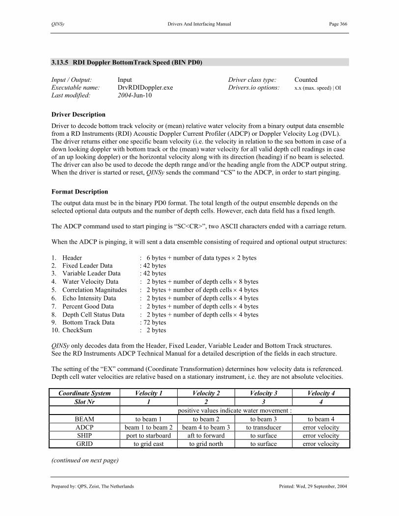
QINSy Drivers And Interfacing Manual Page 366
Prepared by: QPS, Zeist, The Netherlands Printed: Wed, 29 September, 2004
3.13.5 RDI Doppler BottomTrack Speed (BIN PD0) Input / Output: Input Driver class type: Counted Executable name: DrvRDIDoppler.exe Drivers.io options: x.x (max. speed) | OI Last modified: 2004-Jun-10
Driver Description
Driver to decode bottom track velocity or (mean) relative water velocity from a binary output data ensemble from a RD Instruments (RDI) Acoustic Doppler Current Profiler (ADCP) or Doppler Velocity Log (DVL). The driver returns either one specific beam velocity (i.e. the velocity in relation to the sea bottom in case of a down looking doppler with bottom track or the (mean) water velocity for all valid depth cell readings in case of an up looking doppler) or the horizontal velocity along with its direction (heading) if no beam is selected. The driver can also be used to decode the depth range and/or the heading angle from the ADCP output string. When the driver is started or reset, QINSy sends the command “CS” to the ADCP, in order to start pinging.
Format Description
The output data must be in the binary PD0 format. The total length of the output ensemble depends on the selected optional data outputs and the number of depth cells. However, each data field has a fixed length. The ADCP command used to start pinging is “SC<CR>”, two ASCII characters ended with a carriage return. When the ADCP is pinging, it will sent a data ensemble consisting of required and optional output structures: 1. Header : 6 bytes + number of data types × 2 bytes 2. Fixed Leader Data : 42 bytes 3. Variable Leader Data : 42 bytes 4. Water Velocity Data : 2 bytes + number of depth cells × 8 bytes 5. Correlation Magnitudes : 2 bytes + number of depth cells × 4 bytes 6. Echo Intensity Data : 2 bytes + number of depth cells × 4 bytes 7. Percent Good Data : 2 bytes + number of depth cells × 4 bytes 8. Depth Cell Status Data : 2 bytes + number of depth cells × 4 bytes 9. Bottom Track Data : 72 bytes 10. CheckSum : 2 bytes QINSy only decodes data from the Header, Fixed Leader, Variable Leader and Bottom Track structures. See the RD Instruments ADCP Technical Manual for a detailed description of the fields in each structure. The setting of the “EX” command (Coordinate Transformation) determines how velocity data is referenced. Depth cell water velocities are relative based on a stationary instrument, i.e. they are not absolute velocities.
Coordinate System Velocity 1 Velocity 2 Velocity 3 Velocity 4 Slot Nr 1 2 3 4
positive values indicate water movement : BEAM to beam 1 to beam 2 to beam 3 to beam 4 ADCP beam 1 to beam 2 beam 4 to beam 3 to transducer error velocity SHIP port to starboard aft to forward to surface error velocity GRID to grid east to grid north to surface error velocity
(continued on next page)

QINSy Drivers And Interfacing Manual Page 367
Prepared by: QPS, Zeist, The Netherlands Printed: Wed, 29 September, 2004
Decoding Notes
Default behaviour for the RDI driver are to decode the horizontal bottom track velocity for a down looking doppler, when a speed observation is connected, to return the (true) heading of the velocity vector, when a bearing observation is connected, and to perform the checksum. If the coordinate transformation system is a “BEAM” system, the driver just returns the mean value of the four beams, so this setting is not to be used. If a specific beam has been selected in DbEdit, the driver just returns the velocity value of this beam and the heading angle from the Variable Leader Data., otherwise the length and direction of the horizontal velocity vector is used. For a down looking doppler with bottom track, this is the observed velocity with respect to the sea bottom; for an up looking doppler, this is the mean value of all the observed velocities for all depth cells. To change the default behaviour of the driver, change command line parameters in the “DRIVERS.IO” file.
Interfacing Notes
The RS-232 cable connection must have two-way direction, both receiving (Rx) and transmitting (Tx) data, since the QINSy RDI driver will send a command to the unit to start pinging and will receive data ensembles.
Database Setup
See description under “SPEEDLOG SYSTEM DRIVERS”. Do not enter a slot number (or enter slot number 0) if the horizontal velocity is to be computed. Enter a slot number (1 to 4) if just the velocity value for a specific beam or direction (1 to 4) is to be returned. See the coordinate system table above for possible beam or direction slots. Be sure to enter identical slot numbers. To decode the altitude of the ADCP from bottom track ranges, add an “Observation” of type “ROV altitude” to the database, and connect this observation to the doppler system. For an up looking doppler, a zero value is returned. For a down looking doppler, a mean or specific altitude is returned, depending on the slot as above. To decode the heading of the doppler sensor ,add a “System” of type “Gyro’s and Compasses” to the database. See description under “GYRO SYSTEM DRIVERS”. Select the driver “RDI Doppler Bottom Track (Heading)” and fill in the appropriate port settings (note that the port settings can be the same as the RDI Doppler Speedlog system). For the gyro observation use the slotnumber “HDG” for slot 1. To decode roll and pitch for the doppler sensor, add a “System” of type “Pitch, Roll and Heave Sensor” to the database. See description under “PITCH, ROLL AND HEAVE SENSOR DRIVERS”. Select the driver “RDI Doppler Bottomtrack P-R” and fill in the appropriate port settings (note that the port settings can be the same as the RDI Doppler Speedlog system). To decode the environmental data (temperature, speed, depth, salinity and pressure) from the doppler sensor, add a “System” of type “Miscellaneous” to the database. Select the driver “RDI Doppler Bottom Track (Generic)” and add the new generic observations you want to decode. Fill in the appropriate port settings (note that the port settings can be the same as the RDI Doppler Speedlog system). Use the following slot ids for the observations: Temperature: “TMP”. Speed: “SND” Salinity: “SAL” Depth: “DPT” Pressure: “PRS”

QINSy Drivers And Interfacing Manual Page 368
Prepared by: QPS, Zeist, The Netherlands Printed: Wed, 29 September, 2004
Drivers.io Options
The QINSy RDI driver has the possibility to validate the speed data that is being decoded. To use this feature the user has to manually edit the “DRIVERS.IO” file. Any number that is present as command line argument will used as the maximum speed to be accepted by the driver.

QINSy Drivers And Interfacing Manual Page 369
Prepared by: QPS, Zeist, The Netherlands Printed: Wed, 29 September, 2004
3.13.6 RDI Doppler BottomTrack Speed (PD6) Input / Output: Input Driver class type: Terminated <LF> Executable name: DrvRDIDopplerPD6.exe Drivers.io options: x.x (max. speed) Last modified: 1999-Jul-13
Driver Description
Driver to decode bottom track velocity and direction from an ASCII output data ensemble from a RD Instruments (RDI) Acoustic Doppler Current Profiler (ADCP) or Doppler Velocity Log (DVL). The driver returns the horizontal velocity along with its direction (heading).
Format Description
The output data must be in the ASCII PD6 format. Each output message is terminated by a CR and LF, all fields in each message are separated by comma’s and located at fixed columns. The number of messages in every data ensemble depends on the selected PD6 commands. This driver expects Bottom-track velocity data, it does not decode the water-mass velocity data. 1) System Attitude Data (“:SA”-message)
Pitch, Roll and Heading (All not used) 2) Timing and Scaling Data (“:TS”-message)
Date and Time, Salinity, Temperature, Depth, Speed of sound, BIT result code (All not used) 3) Water-mass Instrument/Ship/Earth-referenced Velocity Data (“:WI”, “:WS”, “:WE”-messages)
Three velocity components and a status flag (All not used) 4) Bottom-track Ship-referenced Velocity Data (“:BS”-message)
Transverse velocity data in mm/s (+ = port to starboard movement), Longitudinal velocity data in mm/s (+ = aft to forward movement), Normal velocity data in mm/s (+ = bottom to surface movement), Status of velocity data (“A” = Good, “V” = Bad) Format: “:BS, �TTTTT,�LLLLL, �NNNNN,S<CR><LF>”
5) Bottom-track, Earth-referenced Velocity Data (“:BE”-message) East velocity data in mm/s (+ = east movement), North velocity data in mm/s (+ = north movement), Upward velocity data in mm/s (+ = bottom to surface movement), Status of velocity data (“A” = Good, “V” = Bad) Format: “:BE, �EEEEE, �NNNNN, �UUUUU,S<CR><LF>”
All other messages are not used. (continued on next page)

QINSy Drivers And Interfacing Manual Page 370
Prepared by: QPS, Zeist, The Netherlands Printed: Wed, 29 September, 2004
Format Example :SA, +2.68, +1.45,223.35 :TS,99070613295148,35.0, +8.5, 0.0,1484.0, 0 :BI,-32768,-32768,-32768,-32768,V :BS,-32768,-32768,-32768,V :BE,-32768,-32768,-32768,V :BD, +123.98, +250.44, +111.70, 0.00, 3.55 :SA, +2.81, +1.29,223.58 :TS,99070613295172,35.0, +8.4, 0.0,1484.0, 0 :BI,-32768,-32768,-32768,-32768,V :BS,-32768,-32768,-32768,V :BE,-32768,-32768,-32768,V :BD, +124.07, +250.47, +111.71, 3.47, 3.79 :SA, +2.73, +1.43,223.45 :TS,99070613295196,35.0, +8.4, 0.0,1484.0, 0 :BI, +322, -256, +171, -228,A :BS, +47, -409, +171,A :BE, +248, +329, +171,A :BD, +124.15, +250.53, +111.73, 3.31, 0.24
Decoding Notes
The Bottom-track, Ships referenced Velocity data message (“:BS”) will be used automatically when the direction observation is of Type “Angle”, and the Bottom-track, Earth referenced Velocity data message (“:BE”) is used when the direction observation is Type “Bearing, True”.
Interfacing Notes
No special two-way RS-232 cable connection is required. The driver does not send any command to the doppler, so the unit should already be in continuous data output mode.
Database Setup
See description under “SPEEDLOG SYSTEM DRIVERS”. The unit for the Speed observation should be meters/second, the recommended a priori sd 0.1. The unit for the Angle observation should be degrees, the recommended a priori sd 5.0.
Drivers.io Options
The QINSy RDI driver has the possibility to validate the speed data that is being decoded. To use this feature the user has to manually edit the “DRIVERS.IO” file. Locate the DrvRDIDopplerPD6.exe driver. Any number that is present as command line argument will used as the maximum speed to be accepted by the driver. Furthermore, whenever the status of the velocity data is bad (“V”), it is not accepted by the driver and will not be used by QINSy.

QINSy Drivers And Interfacing Manual Page 371
Prepared by: QPS, Zeist, The Netherlands Printed: Wed, 29 September, 2004
3.13.7 RDI Doppler BottomTrack (Remote Cherry) Input / Output: Input Driver class type: Terminated <ESC> Executable name: DrvRDIRemoteCherry.exe Drivers.io options: x.x (max. speed) Last modified: 2000-May-10
Driver Description
Driver to decode bottom track forward and starboard velocity from an ASCII output data ensemble from a RD Instruments (RDI) Acoustic Doppler Current Profiler (ADCP), using the Remote Cherry Display Output Format. The driver returns the horizontal velocity along with its direction (heading).
Format Description
With bottom tracking data available: <ESC>1Affff.f<ESC>2Assss.s<ESC>4Axxxx.x Where: <ESC>: ESC character (1BHex, 27dec) 1A: Identifier for forward velocity ffff.f Forward Velocity in knots, relative to the bottom 2A: Identifier for starboard velocity ssss.s Starboard Velocity in knots, relative to the bottom 4A: Identifier for ??? xxxx.x ??? When no bottom tracking data available: <ESC>1Affff.f<ESC>2Assss.s<ESC>4A <ESC>4A (WATER VELOCITY) Where: <ESC>: ESC character (1BHex, 27dec)
1A: Identifier for forward velocity ffff.f Forward Velocity in knots, relative to water 2A: Identifier for starboard velocity ssss.s Starboard Velocity in knots, relative to water 4A: Identifier for ??? ______ Space Characters (20Hex, 32dec) 4A: Identifier for ??? Space Characters ??? Format Example ( means the ESC character) 1A 0.0.2A -0.0.4A 8.4 1A 0.0.2A -0.0.4A 8.4 1A 0.0.2A -0.0.4A
8.4 1A 0.0.2A -0.0.4A 8.4 1A 0.0.2A -0.0.4A 8.4 1A 0.0.2A -0.0.4A 8.5 (continued on next page)

QINSy Drivers And Interfacing Manual Page 372
Prepared by: QPS, Zeist, The Netherlands Printed: Wed, 29 September, 2004
Decoding Notes
The driver always wants to receive velocity relative to the bottom (See format A)) The defined Direction observation (Db Setup) should always be of Type “Angle” (not Bearing, True).
Interfacing Notes
No special two-way RS-232 cable connection is required. The driver does not send any command to the doppler, so the unit should already be in continuous data output mode.
Database Setup
See description under “SPEEDLOG SYSTEM DRIVERS”. The unit for the Speed observation should be meters/second, the recommended a priori sd 0.1. The unit for the Angle observation should be degrees, the recommended a priori sd 5.0.
Drivers.io Options
The QINSy RDI driver has the possibility to validate the speed data that is being decoded. To use this feature the user has to manually edit the “DRIVERS.IO” file. Locate the DrvRDIRemoteCherry.exe driver. Any number that is present as command line argument will used as the maximum speed to be accepted by the driver.

QINSy Drivers And Interfacing Manual Page 373
Prepared by: QPS, Zeist, The Netherlands Printed: Wed, 29 September, 2004
3.14 TIDE GAUGE DRIVERS
Database Setup
Tide gauge systems are not connected to an “Object”. Select item “Auxiliary Systems” and define a new “Tide gauge”. Select the appropriate driver and interface parameters. Press the “Next” button to continue the setup. Press the “Add Tide” button to add tide height observations to the system. First a (fixed) node for the tide gauge station has to be defined. The actual tide observation is named after this node. Depending on the driver, generic observations can be defined to decode other data from the input data. If needed, enter the slot number(s). Press “Next” to define the observation properties. Select each tide and enter its parameters. Press the “Apply” button before selecting another tide observation. Press “Finish” button to save the system.

QINSy Drivers And Interfacing Manual Page 374
Prepared by: QPS, Zeist, The Netherlands Printed: Wed, 29 September, 2004
Database Setup (continued)
A new observation can be added by pressing the “Add” button; to remove it, select it and press “Remove”.

QINSy Drivers And Interfacing Manual Page 375
Prepared by: QPS, Zeist, The Netherlands Printed: Wed, 29 September, 2004
Database Setup (continued)
A new tide gauge can be added by pressing the “Add Tide” and buttons. First, enter all the tidal stations. Then select a tide gauge from the list of available nodes and press “OK” to add a tide observation.

QINSy Drivers And Interfacing Manual Page 376
Prepared by: QPS, Zeist, The Netherlands Printed: Wed, 29 September, 2004
Database Setup (continued)
The properties of each observation, for example unit and calibration values, can be entered after selecting it.
Note 1. In QINSy, tide observation heights are assumed to be defined on the survey datum. Therefore, any height difference between the tide gauge datum and the survey datum should be entered as a (C-O) value. Note 2. Also enter a (C-O) value if the tide datum is different in height from the geoid or mean sea level if the geoid separation option is used in the height settings in the QINSy Controller (“Settings – Height”). Note 3. To change tide gauge station properties (name and coordinates) after first definition, expand the fixed node item under the tide gauge system entry in the database setup tree, and select and edit the station. See for more information the QINSy DB Setup Help Topics or the QINSy Knowledge Base.

QINSy Drivers And Interfacing Manual Page 377
Prepared by: QPS, Zeist, The Netherlands Printed: Wed, 29 September, 2004
3.14.1 DCI SBU92 Tide Gauge (Selected Data)
3.14.2 DCI SBU92 Tide Gauge (Snelpeil Data) Input / Output: Input (one-way) Driver class type: Counted Executable name: DrvDCISBU92.exe Drivers.io options: RAW | SEL| NOCS Last modified: 2004-Jul-22
Driver Description
Driver to decode tide heights as transmitted by a DCI SBU92 Radio Tide Gauge, either in ‘Snelpeilbericht’ output format or ‘Geselecteerde Data’ output format. ‘Snelpeilbericht’ messages contain multiple channels (slots). Some slots contain tide heights, while other slots contain wind speed or direction, or pressure.
Format Description
Data messages are always ASCII. Length of data message depends on the format and the number of slots. DCI SBU92 Radio Tide Gauges ‘Snelpeilbericht’ Output Format (793 bytes) [01+nnnC/02+nnnC/03+..../99hhmmC] [ opening bericht 01 kanaalnummer 1 (slot) nnn numerieke waarde (ASCII) C checksum van het kanaal / scheidingsteken kanalen hhmm tijdweergave (geen +/-) ] einde bericht Two example strings logged onboard ZWAAN 1999-06-14 (line feeds and spaces added) [01+068V/02+113^/03+125Z/04+223Z/05+143X/06-999B/07+220Z/08+204W/09+211X/10+229W/ 11+213]/12+169R/13+090X/14+057T/15+038T/16+082T/17-010Z/18-006T/19-010X/20+010b/ 21+018Y/22-005Z/23+002^/24+045V/25+106W/26+076P/27+197K/28+060U/29+161R/30+083W/ 31+127W/32+213Z/33-008U/34+009U/35-025T/36+237P/37-007R/38+999?/39-999</401338M/ 41+249Q/42+006Y/43+075R/44+347O/45+073R/46+001Z/47+078K/48+341Q/49+080P/50+025Y/ 51+049R/52+350V/53+091S/54+084P/55+103W/56+000Z/57+070R/58+999=/59+999</60+007X/ 61+174R/62+152U/63+164Q/64+169K/65+193M/66+078J/67+178H/68+167I/69+170N/70+164S/ 71+345Q/72+078M/73+186L/74+195K/75+999>/76+999=/77+169G/78+141P/79+178E/80+075Q/ 81+178L/82+171R/83+162Q/84+180P/85+158J/86+158I/87+056K/88+040Q/89+054K/90+999A/ 91+999@/92+051T/93+057M/94+047M/95-999:/96+093J/97+045L/981406D/991338?] [01+070]/02+116[/03+126Y/04+220]/05+145V/06+171V/07+220Z/08+204W/09+212W/10+230_/ 11+214\/12+173W/13+093U/14+059R/15+040[/16+082T/17-010Z/18-008R/19-011W/20+012`/ 21+019X/22-003\/23+004\/24+047T/25+112Z/26+078N/27+199I/28+061T/29+163P/30+083W/ 31+129U/32+217V/33-008U/34+011\/35-025T/36+240V/37-007R/38+999?/39-999</401339L/ 41+250Y/42+007X/43+080V/44+342T/45+083Q/46+000[/47+070S/48+349I/49+078I/50+025Y/ 51+046U/52+351U/53+084Q/54+084P/55+103W/56+001Y/57+073O/58+999=/59+999</60+007X/ 61+174R/62+152U/63+164Q/64+169K/65+193M/66+078J/67+178H/68+167I/69+170N/70+164S/ 71+347O/72+085O/73+186L/74+195K/75+999>/76+999=/77+169G/78+141P/79+178E/80+075Q/ 81+178L/82+171R/83+162Q/84+180P/85+158J/86+158I/87+056K/88+040Q/89+054K/90+999A/ 91+999@/92+051T/93+057M/94+047M/95-999:/96+092K/97+045L/981406D/991339>]

QINSy Drivers And Interfacing Manual Page 378
Prepared by: QPS, Zeist, The Netherlands Printed: Wed, 29 September, 2004
DCI SBU92 Radio Tide Gauges ‘Geselecteerde Data’ Output Format (14 bytes) $1AO+00nnn.00<CR> 1 selectieadres (slot) AO Analoog Output command nnn numerieke waarde kanaal <CR> afsluiting bericht TWO example strings logged onboard ZWAAN 1999-06-14 $1AO+00240.00<CR>$1AO+00205.00<CR>
Decoding Notes
Data is timetagged when the header of a data message is received, i.e. "[01" for ‘Snelpeilbericht’ format, or "$" for ‘Geselecteerde Data’ format. Tide values are multiplied by 0.01 to convert from cm to meters. ‘Snelpeilbericht’ channel strings include a checksum character: 128 - ( sum six chars % 128 ). Example. CheckSum "01+068" is 48+49+43+48+54+56 = 298%128 = 42-128 = -86; 86 = 'V'.
Drivers.io Options
Command line parameter “RAW” will decode ‘Snelpeilbericht’ data messages and “SEL” will decode ‘Geselecteerde Data’ messages. “NOCS” will not check the checksum in ‘Snelpeilbericht’ channels.
Database Setup
See description under “TIDE GAUGE SYSTEM DRIVERS”.

QINSy Drivers And Interfacing Manual Page 379
Prepared by: QPS, Zeist, The Netherlands Printed: Wed, 29 September, 2004
3.14.3 Digitrans Radio Tide Gauge (PAH) Input / Output: Input (one-way) Driver class type: Counted Executable name: DrvDigitransPAH.exe Drivers.io options: format | NOCS Last modified: 2000-Feb-16
Driver Description
Driver to decode tide heights as transmitted by a Digitrans radio link, such as the one used by PAH (Port Autonome du Havre) in France. A complete data message contains 48 sequences (16 channels times 3). Some channels contain tide heights, while other channels contain wind speed or direction, or pressure.
Format Description
Data will be partly ASCII and partly binary (BCD). Each message consists of 5 bytes, including a prefix byte (ASCII “M”) and a checksum byte. Data is transmitted according to the CCITT V21 norm (300 bps). Digitrans format
Byte Type Description Values, Units 01 ASCII prefix identifier ASCII “M” (0x4D Hex) 02 ASCII channel number “0” to “?” (0x30 to 0x3F) 03 BCD channel value 1 decameters & meters 04 BCD channel value 2 decimeters & centimeters 05 Hex checksum value AND logic
Decoding Notes
Data is timetagged when a new “M0” sequence is received. Data is updated when the maximum channel, entered in DbSetup, is received. The channel that is decoded corresponds to the slot of a tide observation.
Drivers.io Options
Command line parameters SOL1 and SOL2 can be used to decode a slightly different format. The SOL1 and SOL2 formats consist of 3 sequences per channel, the first one containing BCD digit of meters, the second one decimeters and the third one centimeters. However, these formats have not been tested with real data.
Database Setup
See description under “TIDE GAUGE SYSTEM DRIVERS”. Tide Observation Slot. Enter channel number to be decoded as tide observation slot number. Available slot numbers are 0, 1, 2, 3, 4, 5, 6, 7, 8, 9, and :, ;, <, =, >, ?, or 10, 11, 12, 13, 14, 15. (“:” equal to “10”, etc.).

QINSy Drivers And Interfacing Manual Page 380
Prepared by: QPS, Zeist, The Netherlands Printed: Wed, 29 September, 2004
3.14.4 Hymedis Tide Input / Output: Input (one-way) Driver class type: Executable name: DrvHymedisUI.exe Drivers.io options: none Last modified: 2004-Jun-9
Driver Description
This driver gets tidal information from Hymedis. To use this driver and internet connection (LAN, GPRS, UMTS) is required. The driver has user interface to set a user name and password, for accessing Hymedis data.
When the correct user name and password are entered, the user can click the Log on buton to request data from hymedis. When the driver is re-started the user name and password will be loaded from the registry. The tidal information will be requested every Request interval. This value is user definable from 1 to 30 minutes. The Tide stations… button will open a new dialog which is shown below.
When a tide station is selected the information of that station will be shown. Only stations that transmit a “WH1” will be visible. The Slot Number is identical (Case sensitive) to the slot number that is to be entered in the Database Setup program.

QINSy Drivers And Interfacing Manual Page 381
Prepared by: QPS, Zeist, The Netherlands Printed: Wed, 29 September, 2004
The Save… button can be used to save all station information to a text file:
Decoding Notes
The tidal values can be sent to QINSy using three different corrections: NAP, GLLWS and TAW. Which model is to be used can be selected as seen below:
Database Setup
See description under “TIDE GAUGE SYSTEM DRIVERS”.

QINSy Drivers And Interfacing Manual Page 382
Prepared by: QPS, Zeist, The Netherlands Printed: Wed, 29 September, 2004
3.14.5 Kuhnt Pegel Tide Gauge Input / Output: Input (two-way) Driver class type: Interrogated Executable name: DrvKuhntPegel.exe Drivers.io options: None Last modified: 2004-Feb-13
Driver Description
Driver to decode tide height observations from a Kuhnt Pegel tide gauge receiver. The QINSy driver interrogates the receiver for new data. It can handle multiple tide observations from one transmitter. Tide gauge id’s are entered as slots.
Format Description
To be able to obtain new tide information from the receiver the driver first needs to wake up the receiver by sending an ASCII “S” character. The receiver answers with an ASCII “A” character if it is ready. To obtain the tide information from a single tide gauge the driver send the “Bild 4” command: “Bild 4” command
Byte Description Values, Units 01 Command identifier ASCII “J” (0x4A Hex)
02-04 ? not used, always <SPACE> (0x20 Hex) 05 Separator <SPACE> (0x20 Hex)
06-13 Tide gauge identifier i.e. “49565621” 14 - always “:” (0x3A Hex) 15 Separator <SPACE> (0x20 Hex)
16-19 Measurement identifier always “0010” for tide observation 20 Terminator <CR> (0x0D Hex)
Subsequently the receiver answers with a “Bild 9 command which is encoded as follows: “Bild 9” command
Byte Description Values, Units 01 Command identifier ASCII “M” (0x4D Hex)
02-09 Tide gauge identifier i.e. “49565621” 10 - always “:” (0x3A Hex) 11 Separator <SPACE> (0x20 Hex)
12-15 Measurement identifier always “0010” for tide observation 16 Separator <SPACE> (0x20 Hex) 17 Water level status indicator “s” = rising, “f” = falling, “D”=constant,
“?” = unknown, “T” = old data 18 Separator <SPACE> (0x20 Hex)
19-23 Height of water level in centimeters, “#####” = no data. 24 Quality indicator “!” = data older than 1 minute, “#” = no data. 20 Terminator <CR> (0x0D Hex)

QINSy Drivers And Interfacing Manual Page 383
Prepared by: QPS, Zeist, The Netherlands Printed: Wed, 29 September, 2004
Example of a valid “Bild4” request: J 09460040 0010<CR> Example of a valid “Bild9” response: M09460040: 0010 f 0314<CR> When the driver receives the “Bild 9” message from the receiver it confirms the reception by sending an ASCII ”A” character to indicate succesfull delivery. The whole command response sequence is repeated for each defined tide gauge observation.
Interfacing Notes
Because the QINSy driver needs to send commands to the Kuhnt Pegel receiver to get a response, it is important that the cable wiring between the receiver port and the COM port is bi-directional to allow two-way traffic.
Database Setup
See description under “TIDE GAUGE SYSTEM DRIVERS”. Slot 1 Slot 1 of a tide observation must be filled with the tide gauge identifier as mentioned in the “Bild 9” & “Bild 4” message descriptions. Example Slot Numbers: Rechtenfieth 04970030 Dwargast 04960020 Note: It is very important that these slotnmubers are valid. Invalid slot numbers may cause irregular data reception from the tide gauge.

QINSy Drivers And Interfacing Manual Page 384
Prepared by: QPS, Zeist, The Netherlands Printed: Wed, 29 September, 2004
3.14.6 Pacific Crest Tide Gauge Input / Output: Input (one-way) Driver class type: Terminated Executable name: PacificCrestTide.ini Drivers.io options: none Last modified: 2001-May-07
Driver Description
Driver to decode a tide height observation from a Pacific Crest tide gauge receiver. The driver uses the generic serial input driver with the “PacificCrestTide.ini” file. Note. The name of this driver could be somewhat misleading, since the Pacific Crest Corporation makes several types of radio modems that can be used to transfer all kinds of data, not only tide data messages.
Format Description <CR><LF>··a.aaa···b.bbb···c··d.d··ee·fffff<CR><LF> where “·” denotes a space character and “<CR><LF>” is a Carriage Return – Line Feed pair.
# Format Description Values, Units 1 a.aaa Tide Observation meters 2 b.bbb ??? 3 c ??? 4 d.d ??? 5 ee Quality Indicator 99 = good quality 6 fffff ???
Format Example <CR><LF> 2.112 0.006 0 1.0 99 25581<CR><LF> <CR><LF> 2.104 0.007 0 1.0 99 25586<CR><LF> <CR><LF> 2.098 0.006 0 1.0 99 25591<CR><LF>
Decoding Notes
See description under generic input driver.
Database Setup
See description under “TIDE GAUGE SYSTEM DRIVERS”. The tide value in the example above should be subtracted from a local mean sea level value to obtain the real tide height value. Keeping in mind that QINSy first adds the (C-O) correction, then applies the (C/O) scale factor, enter the negative MSL value as (C-O) correction and enter –1 as scale factor for the tide observation. (MSL – tide) = - (tide + (– MSL))

QINSy Drivers And Interfacing Manual Page 385
Prepared by: QPS, Zeist, The Netherlands Printed: Wed, 29 September, 2004
3.14.7 Sonar Research LPM23 Tide Gauge Input / Output: Input Driver class type: Terminated <LF> Executable name: DrvSonarResearchLPM23.exe Drivers.io options: none Last modified: 1999-Apr-27
Driver Description
Driver to decode tide heights and system data (datum, gain, noise, voltage status and speed of sound) from the Sonar Research LPM23 Tide Gauge.
Format Description
Data will be ASCII and each line is terminated with a carriage return (CR) and line feed (LF).
# Format Description Values, Units 01 à start of string
02-03 nn unit number 04 = header
05-06 RR ? 07-08 nn length
09 U ? 10-15 yymmdd date year / month / day (tide computer) 16-21 hhmmss time hour / min / sec (tide computer) 22-25 nnnn tide level Centimeters 26-29 nnnn datum 30-31 nn gain 32-33 nn noise 34-35 nn voltage status 36-37 nn status 00 = OK 38-41 nnnn speed of sound meters / sec 42-43 hh checksum 01 to 41 44-45 <CR><LF> record termination
Format Example à01=RR21U990422152821027600002521030017308E<CR><LF>
Decoding Notes
This driver will decode a tide observation as a tide gauge system and 5 generic observations (datum, gain, noise, voltage status and speed of sound) as a miscellaneous system. You can use the “Quality Indicator” alert (raw data alert) of the Alert display to check the validity of the depth observation. (continued on next page)

QINSy Drivers And Interfacing Manual Page 386
Prepared by: QPS, Zeist, The Netherlands Printed: Wed, 29 September, 2004
Database Setup
See description under “TIDE GAUGE SYSTEM DRIVERS”. Default serial interfacing parameters for the Sonar Research LPM23 are 1200 baud, 8 data bits, 2 stop bits and no handshaking. Enter “1” for the slot number for the tide gauge observation (see also table below). The tide observation is defined at a “Fixed Node”. The driver only decodes tide heights from one tide gauge. If the (local) tide datum at the transmitter unit and the survey datum do not coincide, the separation in height between the two datums should be entered as “Property” of the tide observation, i.e. as “Fixed system C-O”. The other values contained in the data string can also be decoded and displayed in QINSy, for example in the Timeplot and Alphanumerics displays. Such data is also stored in the QINSy database if data is logged, and as such can also be examined with the QINSy Analyse tool (DbRawInspect). Add five (5) “Observations” of type “Generic” to the tide gauge system (Datum, Gain, Noise, Voltage Status and Speed of Sound) or add these observations to a new “Miscellaneous system” with the same driver name and interface parameters. Enter the slot number for each generic observation according to the following table:
Slot Value 1 Tide 2 Datum 3 Gain 4 Noise 5 Voltage Status 6 Speed of Sound

QINSy Drivers And Interfacing Manual Page 387
Prepared by: QPS, Zeist, The Netherlands Printed: Wed, 29 September, 2004
3.14.8 Valeport 700 Tide Gauge Input / Output: Input (one-way) Driver class type: Terminated Executable name: Valeport700Tide.ini Drivers.io options: none Last modified: 2000-Apr-18
Driver Description
Driver to decode a tide height observation from a Valeport 700 tide gauge receiver. This driver uses the generic input driver with the above mentioned ini-file.
Format Description <S>DDDDD<CR>
# Format Description Values, Units 1 <S> Sign + or – 2 DDDDD Tide millimeters 3 <CR> Carriage Return
Format Example +00732
Decoding Notes
See description under generic input driver.
Database Setup
See description under “TIDE GAUGE SYSTEM DRIVERS”.

QINSy Drivers And Interfacing Manual Page 388
Prepared by: QPS, Zeist, The Netherlands Printed: Wed, 29 September, 2004
3.14.9 Van Essen RGC920 Tide Gauge Input / Output: Input (two-way) Driver class type: Interrogated Executable name: DrvRGC920.exe Drivers.io options: CM | TCM Last modified: 1999-Oct-12
Driver Description
Driver to decode tide height observations and response codes from a Van Essen RGC920 tide gauge receiver. The QINSy driver interrogates the receiver for new data. It can handle multiple tide observations from more than one transmitter and more than one channel. Transmitter, channel and tide gauge are entered as slots.
Format Description
The command protocol to request new data from the tide gauge receiver consists of 6 bytes as follows: T n1 C n2 n3 <CR> ‘T’ 1 byte Transmitter n1 1 byte transmitter number 0-9,A-F ‘C’ 1 byte Channel n2 1 byte channel number 1-6 n3 1 byte channel Method P,A,D <CR> 1 byte ASCII 13 The response can be positive or negative. The data format for a positive response contains 37 bytes: <#1> 16 bytes identification <#2> 10 bytes observation value <#3> 6 bytes observation unit <CR> 1 byte ASCII 13 <#1> 3 bytes response code <CR> 1 byte ASCII 13 The format in case of a negative response only contains the error in the form of a code of 4 bytes: <#1> 3 bytes response code <CR> 1 byte ASCII 13 The most important response codes are given below. See RGC920-Rx/M Manual Appendix C. 101 transmitter not updated 102 transmitter not received 2x0 channel ‘x’ data OK 2x5 channel number wrong 2xn other channel data error 3xn battery power low or high (continued on next page)

QINSy Drivers And Interfacing Manual Page 389
Prepared by: QPS, Zeist, The Netherlands Printed: Wed, 29 September, 2004
Decoding Notes
The response codes are transferred to the quality indicators of the tide observations that are defined for a certain transmitter-channel combination. These quality indicators can be shown in a Observation Physics display. If a response is negative (or positive with a non-valid data code), i.e. in case of an error, the quality indicators will give the negative code and the tide value and time will not be updated. For positive responses, the quality indicator will give the positive code. If an observation did not update, the indicator will be 0. The driver checks the observation code for “CM” or “DM” and if found, converts the tide value to meters.
Interfacing Notes
Because the QINSy driver needs to send commands to the RGC920 receiver to get a response, it is important that the cable wiring between the receiver port and the COM port is bi-directional to allow two-way traffic. The cable wiring must follow the full RS-232C protocol, i.e. connect also the Request to Send and Clear to Send wire (see APPENDIX A: RS-232 Connector Pin Assignments). According to the RGC920 manual the I/O parameters should be 9600 baud, 8 databits, 1 stopbit, no parity.
Database Setup
See description under “TIDE GAUGE SYSTEM DRIVERS”. Slot 1 Slot 1 of a tide observation must be the first part of the identification field in a response message. Usually this is the name of the tide gauge. It is not required to enter a full name, as long as the first characters match exactly. E.g., tide station Dintelhaven identifies itself with DINTELHAVEN, but you can fill in for slot 1 the name DINTEL. Notice that a slot 1 number must be unique for a transmitter-channel-method combination. Slot 2 Slot 2 of a tide observation must denote the transmitter (zender) number for the corresponding tide station.
Drivers.io Options
The channel number (kanaal) will be default “1” and the method is default “P”. To change the default values for channel number and method, use different command line parameters in the Drivers.io file, located in the QINSy program folder. Search in this file for the driver entry “DrvRGC920.exe 1P”. The first parameter (1) is the channel number and the second parameter (P) indicates the method. Do not alter the length of the line.

QINSy Drivers And Interfacing Manual Page 390
Prepared by: QPS, Zeist, The Netherlands Printed: Wed, 29 September, 2004
3.14.10 Vyner Medway Radio Tide Gauge MK I
3.14.11 Vyner Medway Radio Tide Gauge MK II Input / Output: Input Driver class type: Terminated <LF> Executable name: DrvVynerMedway.exe Drivers.io options: 1 | 2 Last modified: 2001-Aug-29
Driver Description
Driver to decode tide heights as transmitted by a Vyner Medway Radio Tide Gauge Mark I or Mark II.
Format Description
Data will be ASCII and each line is terminated with a carriage return (CR) and line feed (LF). All the tide heights are measured with respect to the (local) tide datum at the transmitter units. Examples Vyner MK I format: “:1234<CR><LF>” or ”;1234<CR><LF>”
# Format MK I Description MK I Values, Units 01 “:” or “;” start of data “:” (positive) or “;” (negative) 02 xxxx tide height 0.01 metres 03 <CR><LF> record termination
Examples Vyner MK II format: “07/04/93 12:30:10 A+12.34<CR><LF>” or ”A+12.34<CR><LF>”
# Format MK II Description MK II Values, Units 01 dd/mm/yy date of height (optional) day / month / year 02 “ “ field delimiter (optional) “ “ (space) 03 hh:mm:ss time of height (optional) hours : minutes : seconds 04 “ “ field delimiter (optional) “ “ (space) 05 c channel code “A” to “J” 06 s tide sign “+” or “−“ 07 xx.xx tide height metres 08 <CR><LF> record termination
Decoding Notes
Channel code “J” also allows a Medway MK I tide gauge receiver to receive a transmitted tide from a MK II transmitter unit; and code “J” also allows a Medway MK II tide gauge receiver to receive a transmitted tide from a MK I transmitter unit. The channel code that is decoded corresponds to the slot of a tide observation. (continued on next page)

QINSy Drivers And Interfacing Manual Page 391
Prepared by: QPS, Zeist, The Netherlands Printed: Wed, 29 September, 2004
Database Setup
See description under “TIDE GAUGE SYSTEM DRIVERS”. If the (local) tide datum at the transmitter unit and the survey datum do not coincide, the separation in height between the two datums should be entered as “Property” of the tide observation, i.e. as “Fixed system C-O”. The tide observation can be defined at a “Fixed Node”. The present driver can only decode tide heights from one tide gauge, but in the future tide observations from more fixed stations can be decoded (and weighted). Slot. Enter the channel code as slot number. Always enter slot “J” for Vyner MK I observations.

QINSy Drivers And Interfacing Manual Page 392
Prepared by: QPS, Zeist, The Netherlands Printed: Wed, 29 September, 2004
(This page intentionally left blank)

QINSy Drivers And Interfacing Manual Page 393
Prepared by: QPS, Zeist, The Netherlands Printed: Wed, 29 September, 2004
3.15 SURFACE NAVIGATION SYSTEM DRIVERS
Database Setup
First define and select the “Object” on which the system is located. Select item “Systems” and define a new “Surface navigation system”. Select the appropriate driver and interface parameters. Press the “Next” button to continue the setup. Press the “Add” button to add observations to the system. Depending on the type of observation, define the node(s) at which its value is measured (and to which its value is measured). Press “Next” to define the observation properties. Select each observation and enter the appropriate parameters. Press the “Apply” button before selecting another observation. Press “Finish” button to save the system.

QINSy Drivers And Interfacing Manual Page 394
Prepared by: QPS, Zeist, The Netherlands Printed: Wed, 29 September, 2004
Database Setup (continued)
A new observation can be added by pressing the “Add” button; to remove it, select it and press “Remove”.

QINSy Drivers And Interfacing Manual Page 395
Prepared by: QPS, Zeist, The Netherlands Printed: Wed, 29 September, 2004
Database Setup (continued)
A new antenna node can be added by pressing the button; to change its properties, press the button.

QINSy Drivers And Interfacing Manual Page 396
Prepared by: QPS, Zeist, The Netherlands Printed: Wed, 29 September, 2004
Database Setup (continued)
The properties of each observation, for example unit and calibration values, can be entered after selecting it.
Note 1. Be sure to define appropriate a priori SD values for each of the possible (very different) observations. See for more information the QINSy DB Setup Help Topics or the QINSy Knowledge Base.

QINSy Drivers And Interfacing Manual Page 397
Prepared by: QPS, Zeist, The Netherlands Printed: Wed, 29 September, 2004
3.15.1 Artemis Range & Bearing (ASCII)
3.15.2 Artemis Range & Bearing (KA-BCD (0.1))
3.15.3 Artemis Range & Bearing (KA-BCD (0.01)) Input / Output: Input Driver class type: Terminated Executable name: DrvPseudoArtemis.exe Drivers.io options: none / format Last modified: 1999-Sep-02
Driver Description
Driver to decode both distance and azimuth from Artemis output telegrams in BCD or ASCII format. For the ASCII formats, the Artemis driver automatically determines if an ASCII string contains 16 or 17 characters.
Format Description
The following four peripheral output telegram formats are available for use with the QINSy Artemis driver: 1) KA-BCD(0.1) 7 byte BCD telegram, distance resolution of 1.0m, azimuth resolution of 0.01º. 2) KA-BCD(0.01) 7 byte BCD telegram, distance resolution of 1.0m, azimuth resolution of 0.001º. 3) ASCII-16 16 character ASCII string, distance resolution of 0.1m, azimuth resolution of 0.01º. 4) ASCII-17 17 character ASCII string, distance resolution of 0.1m, azimuth resolution of 0.001º.
KA-BCD(0.1) Byte Description Bit 7-6-5-4 Description Bit 3-2-1-0
1 AZM x 100 AZM x 10 2 AZM x 1 AZM x 0.1 3 0000 AZM x 0.01 4 DIST x 10000 DIST x 1000 5 DIST x 100 DIST x 10 6 0000 DIST x 1 7 1111 1111 KA-BCD(0.1)
Byte Description Bit 7-6-5-4 Description Bit 3-2-1-0 1 AZM x 100 AZM x 10 2 AZM x 1 AZM x 0.1 3 AZM x 0.01 AZM x 0.001 4 DIST x 10000 DIST x 1000 5 DIST x 100 DIST x 10 6 0000 DIST x 1 7 1111 1111
(continued on next page)

QINSy Drivers And Interfacing Manual Page 398
Prepared by: QPS, Zeist, The Netherlands Printed: Wed, 29 September, 2004
ASCII-16
Char Description Values 1 DISTANCE x 10000 2 DISTANCE x 1000 3 DISTANCE x 100 4 DISTANCE x 10 5 DISTANCE x 1 6 DISTANCE x 0.1 7 ‘SPACE’ space character (0x20) 8 AZIMUTH x 100 9 AZIMUTH x 10 10 AZIMUTH x 1 11 AZIMUTH x 0.1 12 AZIMUTH x 0.01 13 ‘SPACE’ space character (0x20) 14 ‘READY’ 1 = data valid, 0 = data not valid 15 <CR> carriage return (0x13) 16 <LF> line feed (0x10) ASCII-17
Char Description Values 1 DISTANCE x 10000 2 DISTANCE x 1000 3 DISTANCE x 100 4 DISTANCE x 10 5 DISTANCE x 1 6 DISTANCE x 0.1 7 ‘SPACE’ space character (0x20) 8 AZIMUTH x 100 9 AZIMUTH x 10 10 AZIMUTH x 1 11 AZIMUTH x 0.1 12 AZIMUTH x 0.01 13 AZIMUTH x 0.001 14 ‘SPACE’ space character (0x20) 15 ‘READY’ 1 = data valid, 0 = data not valid 16 <CR> carriage return (0x13) 17 <LF> line feed (0x10)
Decoding Notes
For Artemis data in ASCII format, the quality indicators of the observations reflect the ‘READY’ character in the data string: +1 if the data are valid and –1 if the data are not valid. See Observation Physics display. (continued on next page)

QINSy Drivers And Interfacing Manual Page 399
Prepared by: QPS, Zeist, The Netherlands Printed: Wed, 29 September, 2004
Database Setup
See description under “SURFACE NAVIGATION SYSTEM DRIVERS”. Add a new “Surface Navigation System” to the database and select the appropriate Artemis driver and inter-facing parameters. Press “Next” button to continue the setup. Select a “Fixed Location” as system location. First add an observation of type “Range”. Select or add a fixed “At Node” for the Artemis station, then select or add a variable “To Node” for the receiver antenna. Secondly, add an observation of type “Bearing, true” and select the same fixed “At Node” and variable “To Node” as for the range observation. Press “Next” button to define the observation properties. Select each observation and set the appropriate unit and (C-O) values. Be sure to press button “Apply Properties” to save the changes. Press “Finish” to save the system. Note 1. The azimuth observation in QINSy should always be given with respect to the true north. When the Artemis system outputs azimuth values with respect to another direction, for example grid north, then be sure to enter a (C-O) value for the azimuth observation in QINSy. To correct from grid north to true north, enter the meridian convergence at the Artemis station position as (C-O) value. This value can be obtained using option “Test geodetical parameters”. Enter station coordinates (on survey datum) and press the “Calculate” button to display the results (on survey datum). Enter the convergence with the same sign as (C-O) value. Note 2. QINSy needs three observations to compute a position, while an Artemis system only outputs range and bearing. Usually the third observation will be a height aiding observation for the Artemis system, defined in the Controller under “Settings” – “Heights”. However, it is possible in DB Setup to add a third observation to the Artemis system which can also be used in the computation. Edit the Artemis system and add a third observation of type “Vertical Angle”. Set the unit to degrees. This vertical angle will be computed online from the difference between the antenna heights of the Artemis station node and the vessel node, taking into account the observed range as well as the curvature of the earth. This approach will only work if the distance between the two nodes is large enough and the vessel reference point height is close to survey datum level.
Drivers.io Options
Four command line options are available to select the format: ASCII16, ASCII17, KABCD02, KABCD03. If no format is specified, then the driver assumes an ASCII format and automatically determines the type.

QINSy Drivers And Interfacing Manual Page 400
Prepared by: QPS, Zeist, The Netherlands Printed: Wed, 29 September, 2004
3.15.4 AUV/Buoy Tracking (PARADIGM) Input / Output: Input Driver class type: Terminated <CR> Executable name: DrvAUVBuoyTracking.exe Drivers.io options: none / format / Id Last modified: 2003-July-28
Driver Description
Driver to decode range measurements between an AUV and floating buoys on the watersurface and to decode the GPS positions of these buoys. See chapter POSITIONING NAVIGATION SYSTEM DRIVERS about how to decode the GPS positions from the buoys
Format Description
Example data:
G2,235548,2726.6582,N,07854.6230,W,2,10,0.8,1.6, G3,235548,2725.7536,N,07849.0707,W,2,10,0.8,3.2, G1,235548,2725.6634,N,07847.1891,W,2,10,0.8,0.9, #B0,P,3 P3 P1 P2 #B1,C C1,00,00,B6 #B3,C C3,00,03,B2 #B3,R R3,01,7A02 #B1,C C1,00,00,B7 #B3,C C3,00,01,B3 #B1,C C1,00,00,B7 #B3,C C3,00,01,B3 #B1,C C1,00,00,B7 #B3,C C3,00,01,B3 #B0,G,D #B1,C G3,235600,2725.7539,N,07849.0706,W,2,10,0.8,2.3, G2,235600,2726.6583,N,07854.6229,W,2,10,0.8,1.3, G1,235600,2725.6638,N,07847.1895,W,2,10,0.8,-0.7 #B0,P,3 P3 P1 P2 #B1,C C1,00,00,B6 #B3,C C3,00,03,B2 #B3,R R3,02,7EC1

QINSy Drivers And Interfacing Manual Page 401
Prepared by: QPS, Zeist, The Netherlands Printed: Wed, 29 September, 2004
Database Setup
See description under “SURFACE NAVIGATION SYSTEM DRIVERS”. Define a range observation between each buoy (Vessel object) and the AUV (Vessel object)
The slot number must be the buoy address (decimal buoy identification number, range 1..15)

QINSy Drivers And Interfacing Manual Page 402
Prepared by: QPS, Zeist, The Netherlands Printed: Wed, 29 September, 2004
Further, the driver decodes the traveltime of the sound through water between masterbuoy and AUV and between AUV and the other buoys. Therefore the user must select for each range the unit Seconds, the SoundVelocity must be entered in Survey Units / Seconds and the Fixed or Variable C-O must be used to enter the Turn-Around-Delay, also in seconds. This Turn-Around-Delay should always be entered as a negative number.

QINSy Drivers And Interfacing Manual Page 403
Prepared by: QPS, Zeist, The Netherlands Printed: Wed, 29 September, 2004
3.15.5 Cable Counter (Dynapar, Sidescan Winch)
Input / Output: Input (one-way) Driver class type: Terminated <CR> Executable name: DrvCableCounter.exe Drivers.io options: none Last modified: 2000-April-18
Driver Description
Driver for decoding cable out range observation from a Dynapar cable counter or from a Sidescan Winch. The driver will automatically determine the format of the input data string when the string starts with Dynapar header string “R: Co.”, or if it starts with Sidescan Winch header “L=”.
Format Description
Each Dynapar string has a (fixed) length of 13 bytes, including termination character <CR>. R: Co. RRRRR<CR> where “RRRRR” is the cable out range value in decimeters. Each Sidescan Winch string is terminated by character <CR>. L=x.xm <CR> where x.x is the length of the cable in meters S=x.xm/m<CR> where x.x is the Speed of the cable in meters per minute. (Not used by QINSy)
Decoding Notes
The decoded range observation is always multiplied by 0.1 to convert decimeters to meters for the Dynapar format.
Database Setup
Add a “System” of type “Surface navigation system” to the vessel object in the QINSy database and select the appropriate driver and interfacing parameters. Press “Next” button. Add an observation of type “Range” and select (or add) the node for the tow point (at which the cable out is measured). Add the node on the fish object (to which the cable out is measured) to this range observation and enter a name. Press “Next” button. Select range observation and set its unit to “Meters”. Apply properties and press “Finish” to save system. In order to compute the fish position using the cable out range observation, add a system of type “Manual Layback system” to the vessel object in the QINSy database. Press “Next” button. ). Add the node on the fish object (to which the cable out is measured) to this layback observation and enter a name and sd. “Finish”.

QINSy Drivers And Interfacing Manual Page 404
Prepared by: QPS, Zeist, The Netherlands Printed: Wed, 29 September, 2004
Controller Setup
Online, when a manual layback system has been added to the database, a “Manual Layback Driver” is automatically started by the QINSy Controller. Open the driver window and select the manual layback observation to define its properties. Select layback type “Slant Range” and the cable out range observation. Select the appropriate depth or altitude observation and/or enter the manual height difference between the vessel tow point and the fish node as Delta Z value. If the fish is trailing the vessel, use COG to rotate the layback observation. To compute the fish position, use layback in an computation. See example below.

QINSy Drivers And Interfacing Manual Page 405
Prepared by: QPS, Zeist, The Netherlands Printed: Wed, 29 September, 2004
3.15.6 Cable Counter (Red Lion)
Input / Output: Input (two-way) Driver class type: Interrogated Executable name: DrvRedLionCableCounter.exe Drivers.io options: none Last modified: 1999-Apr-01
Driver Description
Driver to decode cable out range from Red Lion cable counter. The cable counter is interrogated by QINSy, and therefore requires an interface cable that allows bi-directional data communication.
Format Description
Driver sends command <TE*> and then waits for a response.
Decoding Notes
The cable length value is rounded to whole meters (e.g. 2503).
Database Setup
See description under “SURFACE NAVIGATION SYSTEM DRIVERS”. To decode the range, add a “Range” observation connecting the tow point and the fish to the system setup.

QINSy Drivers And Interfacing Manual Page 406
Prepared by: QPS, Zeist, The Netherlands Printed: Wed, 29 September, 2004
3.15.7 Cable Counter Payout (MD Totco)
3.15.8 Cable Counter Tension / Speed (MD Totco) Input / Output: Input Driver class type: Terminated Executable name: DrvTotcoCableCableCounter.exe Drivers.io options: none Last modified: 2002-Feb-14
Driver Description
Driver to decode cable out range (payout) , wire tension and speed from MD Totco cable counter. The cable counter is sending data continuously to QINSy.
Format Description 1234567890123456789012345678901234567890 NN,TTTTTTT,S,PPPPPPP,S,VVVVVVV,S,XXXXCRLF NN Sensor Unit Number sending this data TTTTTTT Tension (float) [lbs.] PPPPPPP Payout (float) [ft] VVVVVVV Speed (float) [ft/min] XXXX Status String
(CAL1, CAL2 = Cal relays active, affects current values, 0000 = OK, 0001 – 9999 = Self Test failed)
S One Character alarm response (H==high-high, h = high, l = low, L =low-low, space = no alarm)
The fields are separated by a comma, and terminated with a CR/LF pair. Example: 01, 60, , 196, , -33, ,0000
Decoding Notes
No conversion factor is applied to the decoded floating-point values. The sensor unit number is ignored. If the status string is 0000 (OK) then the Quality Indicator of the values are set to zero; any other status string will set the Quality Indicators to –1. One Char. Alarm responses are ignored.
Database Setup
See description under “SURFACE NAVIGATION SYSTEM DRIVERS” See description under “MISCELANEOUS SYSTEM DRIVERS”. To decode the Payout, add a “Range” observation connecting the tow point and the fish to the system setup. Make sure to set the units to “International Feet”. For the Tension and Speed fields, generic observations should be defined. First, add a “Miscellaneous system” system to the database and select the “Cable Counter Tension / Speed (MD Totco)” driver, using the same I/O interfacing parameters as with the driver used for the Payout (range). Press “Next” button to define the properties of the generic observations. Apply the appropriate conversion factors if any other units are required then feet and lbs. The slot number should be 1 for the Tension and 2 for the Speed field.

QINSy Drivers And Interfacing Manual Page 407
Prepared by: QPS, Zeist, The Netherlands Printed: Wed, 29 September, 2004
3.15.9 DCI Minilir-Fennel Input / Output: Input Driver class type: Terminated <LF> Executable name: DrvMinilirFennel.exe Drivers.io options: none Last modified: 1997-Jul-25
Driver Description
Driver for combined RS-232 message from DCI Minilir-Fennel telemetry system. Driver to decode both horizontal and vertical angle from Minilir system as well as range observation from Fennel EDM system.
Format Description
Each combined Minilir-Fennel output string is fixed in length. Horizontal and vertical angle measurements are output in turn, each combined with the latest Fennel range. A missing (or invalid) distance is indicated by the data string “_NO_ECHO_”. Some examples of the Minilir-Fennel output message are given below. Byte Format Description Values, Range, Units 01 ‘H‘ or ‘V’ type of angle ‘H’ horizontal , ‘V’ vertical 02 n angle × 100 ° 0…9 03 n angle × 10 ° 0…9 04 n angle × 1 ° 0…9 05 ‘.’ decimal point ‘.’ 06 n angle × 0.1 ° 0…9 07 n angle × 0.01 ° 0…9 08 n angle × 0.00125 ° 0…7 09 ‘Q’ or ‘q’ quality of angle ‘Q’ good, ‘q’ bad 10 ‘A’ type of range ‘A’ range (“afstand”) 11 n range × 1000 m 0…9 12 n range × 100 m 0…9 13 n range × 10 m 0…9 14 n range × 1 m 0…9 15 ‘.’ decimal point ‘.’ 16 n range × 0.1 m 0…9 17 n range × 0.01 m 0…9 18 n range × 0.001 m 0…9 19 ‘O’ age of range ‘O’ age (“ouderdom”) 20 n age × 100 ms 0…9 21 n age × 10 ms 0…9 22 n age × 1 ms 0…9 23 ‘.’ decimal point ‘.’ 24 n age × 0.1 ms 0…9 25 <CR><LF> record terminator <CR><LF>
(continued on next page)

QINSy Drivers And Interfacing Manual Page 408
Prepared by: QPS, Zeist, The Netherlands Printed: Wed, 29 September, 2004
Format Example H193.635QA0864.053O066.9 V013.850QA0864.060O027.5 H193.635QA0864.061O058.7 V013.850QANO ECHO O021.5
Interfacing Notes
According to DCI specifications, the interface parameters are 9600 baud, 7 data bits, even parity, 1 stop bit. The latency of the Minilir-Fennel system is the time interval between the angle measurement (FLAG) in the Minilir system and the reception of the string at the COM port, which includes the time interval between the FLAG and sending the string and the time interval of the radio link between sending and receiving the string. The age of the Fennel range is decoded from the data string. An additional time correction for the length of the Fennel string (actual measurement) is applied as 70.0 ms, according to the latest DCI specifications. The Minilir-Fennel output is an ordinary RS-232 output. See Chapter 1 for general interfacing remarks.
Calibration
Refer for the calibration procedure to the separate MINILIR-FENNEL CALIBRATION MANUAL RWS-MD.
Database Setup
See description under “SURFACE NAVIGATION SYSTEM DRIVERS”. Add “Object” for the vessel with the reflector unit. Add a “Fixed Node” for the Minilir-Fennel station and for all the calibration targets to be used in the calibration procedure. Add two times a “Variable Node” (located on the same vessel object) for both the Minilir spot and the Fennel prism on the reflector unit to be used for online positioning. Be sure to enter the height difference between prism and spot as difference in Z-offset. Both variable nodes should have the same X-offset and Y-offset (with respect to the unit’s reference point), since the Fennel prism node should be defined exactly above (or under) the Minilir spot node. A physical horizontal offset, for example in case of a ring of prisms, should be entered as a correction C4, see below. Add three “Observations”, for the Fennel range and for the Minilir horizontal and vertical angles. Be sure to select the same station node for the fixed “At Node”, but different target nodes for the variable “To Nodes”. Add a “Surface Navigation System” with driver “DCI Minilir-Fennel” and enter the appropriate interfacing parameters and the latency value. Connect the three observations (one range and two angles) to the system. Open the “Station Corrections” tab, select the station node (only one fixed node should have been defined) and enter the corrections H1, C2 and C3; correction H0 is obtained from the instrument height at the node. Open the “Target Corrections” tab, connect all the target nodes to be used during the calibration procedure (fixed nodes) and/or online (one variable node for the Fennel prism), and by selecting the target nodes, enter the corrections C4 and H5. Correction H5 is only used during calibration, but to obtain a consistent printout, H5 should be the same as the height difference between the two variable nodes for the online positioning. Be careful with the signs of the corrections. A height difference dH in upward direction is positive, for example if the Fennel prism is located above the Minilir spot. A range correction dL which should be added to the observed range to get the corrected value to be used in the calibration procedure and/or the online positioning is positive, hence a ring of prisms on a reflector unit will result in a positive correction C4. Carry out a calibration procedure to determine the (additional) instrumental constant for the range and the zero directions for the angle observations. Before starting QINSy for online positioning, edit the database to enter the calibration (C-O) results in the “Fixed (C-O)” or “Variable (C-O)” properties of the three Minilir-Fennel observations. Do not enter any additional “Node Corrections” in the Minilir-Fennel system definition.

QINSy Drivers And Interfacing Manual Page 409
Prepared by: QPS, Zeist, The Netherlands Printed: Wed, 29 September, 2004
3.15.10 Geodimeter 600 Input / Output: Input (two-way) Driver class type: Interrogated Executable name: DrvGeodimeter600.exe Drivers.io options: various Last modified: 2003-Dec-08
Driver Description
Driver for Geodimeter initialisation and decoding of standard output data using a Geodimeter telemetry link. Driver to decode range observation and both horizontal and vertical angles from Geodimeter 600 system.
Format Description
After initialisation, during normal interrogation cycles, the GDM target lock status is requested using the “RG,32” command, and measurement data is requested using the “RG” command. GDM replies:
Request Response Description Locked on Target Prism Signal RG,32 32=0 Target status information No No RG,32 32=1 Target status information No Yes RG,32 32=4 Target status information Yes No RG,32 32=5 Target status information Yes Yes
RG 0 7=<hor ang> 8=<vert ang> 9=<dist>
New distance measured No or Yes Yes
RG 3 7=<hor ang> 8=<vert ang>
No new distance measured No or Yes No
Field Format Description Values, Range, Units
1 x Quality indicator 0 OK. Other values represent errors 2 <cr><lf> Separators separators between data/status lines 3 7=xxx.xxxx Horizontal angle 0 – 360 degrees or 0 – 400 grads 4 <cr><lf> Separators separators between data/status lines 5 8=xxx.xxxx Vertical angle 0 – 360 degrees or 0 – 400 grads 6 <cr><lf> Separators separators between data/status lines 7 9=xxx.xxxx Range 0 – 9999 meters 8 <cr><lf> Separators separators between data/status lines 9 <eot> Terminator end of transmission (ASCII 4)
Interfacing Notes
Geodimeter interface parameters can be set using the keyboard, and are default 9600 baud, 8 data bits, 1 stop bit, no parity. The latency of the Geodimeter system is the interval between the time of receiving the first byte of the standard output data transmission and the time at which the actual measurements have been made. The Geodimeter telemetry output is an ordinary RS232 output. See Chapter 1 for general interfacing remarks. (continued on next page)

QINSy Drivers And Interfacing Manual Page 410
Prepared by: QPS, Zeist, The Netherlands Printed: Wed, 29 September, 2004
Geodimeter Setup and Initialisation
Set up the Geodimeter instrument over a known point (fixed station node). Press the [PWR] button to switch on the instrument. Perform a calibration to determine the corrections to the observations (C-O values) and a station establishment procedure to determine the fixed coordinates of the station node, if needed. Refer for the calibration and station establishment procedures to the GEODIMETER SYSTEM 600 USER MANUAL. Press the [RPU] button to set up the Geodimeter instrument for remote control. Press [3] to choose remote mode and [1] if no station establishment has to be performed. Set the limits of the search sector and measure towards a reference object, if needed. Press [ENT] or another button to switch over to the remote control.
Geodimeter Radio Channel and Address
The radio channel, telemetry radio address and Geodimeter radio address are read from file GEORADIO.txt which is located in the QINSy program directory. This file is created the first time the Geodimeter driver is started. It’s contents can be changed (before going or while being) online, after which a “Reset I/O” can be given to re-initialise the telemetry link. Only change the numbers; do NOT change the comment strings. 1 GEORADIO CHANNEL 1 GEORADIO ADDRESS 1 GEODI600 ADDRESS
Database Setup
See description under “SURFACE NAVIGATION SYSTEM DRIVERS”. Add an “Object” for the vessel with the target unit. Add a “Fixed Node” for the Geodimeter station. Add a “Variable Node” (on the vessel object) for the target unit to be used for online positioning. Be sure to enter right offsets. A physical horizontal offset, in case of a ring of prisms, should be entered as a correction to the range, see below. Add a “Surface Navigation System” with driver “Geodimeter 600 (Active Radio Link)” (Active RS232 Link has not been implemented yet) and enter the appropriate interfacing parameters and latency value. In the system definition wizard select the location(usually fixed), add observations for Range horizontal angle and vertical angle, for each observation select the from and to node. Enter the appropriate slot number, which is the label number in the standard output data transmission, i.e. “9” for range, “7” for horizontal angle, and “8” for vertical angle. See appendix to the USER MANUAL. On the last page of the wizard: Observation unit for the range should be “metres”. Calibration corrections (and prism offset) for the range can be entered under Properties. Observation units for the angles should be “grads”. Calibration corrections can be entered under Properties. The calibration (C-O) values can be entered in the “Fixed (C-O)” or “Variable (C-O)” properties of the three observations. Important Since the horizontal angle is defined as “true bearing” observation, its (C-O) value must reflect the difference between the zero direction in the Geodimeter instrument and true north. The (C-O) correction is added to the observed value before it is used by QINSy. Since the vertical angle is really a zenith angle, measured down-wards from the zenith instead of upwards from the horizon, its scale value (C/O) must be –1 (minus 1). The (C-O) value for the vertical angle must be –100 (minus 100), 100 grads to account for the zenith direction and minus to account for the fact that the general observation reduction equation in the QINSy system (following UKOOA P2/94 format) is defined as Obs reduced = (C/O) { Obs raw + (C-O) fixed + (C-O) variable }. (continued on next page)

QINSy Drivers And Interfacing Manual Page 411
Prepared by: QPS, Zeist, The Netherlands Printed: Wed, 29 September, 2004
Drivers.io Options
Command line parameter description for “drivers.io” file in QINSy directory. By default, the Geodimeter 600 driver is initialized in actively radio controlled tracking mode, with a 10 seconds timeout for a lock failure.
Parameter Description Default Comments C RS-232 control off direct cable connection R radio control off radio link ; same as ‘A’ A active control on or off radio link ; see DRIVERS.IO entry P passive control off or on radio link ; see DRIVERS.IO entry L tracking mode on or off radio link ; see DRIVERS.IO entry F standard mode off measuring mode N passive mode off or on measuring mode ; same as ‘P’
TRK tracking mode on or off measuring mode ; same as ‘L’ STD standard mode off measuring mode ; same as ‘F’ NTC no target check on disables “RG,32” target status command BOX message boxes on off displays radio link status message boxes
nn lock failure count 20 < 100 ; counter before re-initialization nnn command delay in ms 750 > 100 ; milliseconds to delay commands
Parameter “C” can be used for a RS-232 link; parameters “R” and “A” indicate an active radio link while “P” and “N” initialize a passive radio link (not sending commands). Parameters “L” or “TRK” can be used for tracking mode, while “F” or “STD” are used for standard mode. An integer number (less than 100) can be used to set the count of consecutive lock failure status responses (i.e. the “RG,32” responses), before a message (and target search command) is given. An integer number (greater than 100) can be used to set the time interval (milliseconds) between sending a command (i.e. the “RG” request) and reading a response. If the update rate of the Geodimeter system is set to more than one second, the integer number will represent the number of seconds. See below for the driver entries that a presently available in the “drivers.io” file. Remark In case of an active radio link, using a command delay of 750 ms and with the target check enabled, will mean that only one set of measurements every 1.5 seconds will be read. Using “NTC” as command line parameter will decrease the measurement interval to 0.75 seconds, but then the driver will not be able to determine of the target lock is lost. In (default) tracking mode, 0.4 seconds is needed to measure a distance, plus some time to send the data over the radio link, so do not use command delays less than 500 ms. Remark When a passive RS-232 cable link is being used, it is better to use the QINSy DrvGeodimeterGST module. 100077, Geodimeter GST (Passive RS232 Link) , DrvGeodimeterGST.exe 100078, Geodimeter 600 (Passive Radio Link) , DrvGeodimeter600.exe P 20 100079, Geodimeter 600 (Active Radio Link) , DrvGeodimeter600.exe A L 20 750

QINSy Drivers And Interfacing Manual Page 412
Prepared by: QPS, Zeist, The Netherlands Printed: Wed, 29 September, 2004
3.15.11 Geodimeter Aga 140T Input / Output: Input Driver class type: Terminated ‘>’ Executable name: DrvAga140T.exe Drivers.io options: Last modified: 2002-June-19
Driver Description
Driver for Geodimeter Aga 140T. Used for tracking of objects. The Aga 140T measures a range, vertical and horizontal angle. These three values are decoded by the driver.
Format Description
An example of the message sent by the Aga 140T: 0<CR><LF>7=399.9995<CR><LF>8=99.995<CR><LF>9=1999.999<CR><LF>> which will be seen in the IO tester as: 0 field 1 7=399.9995 field 2 8=99.995 field 3 9=1999.999 field 4 > field 5
Field Format Description Values, Range, Units 1 x Quality indicator 0 if ok. All other values represent errors 2 7=xxx.xxxx Horizontal angle 0 – 360 degrees 0 – 400 grads 3 8=xxx.xxxx Vertical angle Degrees or grads 4 9=xxx.xxxx Range Normal mode 0-999 long range 1000-1999 meters5 > Termination character Always ‘>’
Format Example 0 7=57.5422 8=89.5848 9=1995.944 >
Decoding Notes
The decoded angle values are converted to degrees when in grads. The distance measurements are already in meters. The decoded horizontal angle is with respect to the horizontal orientation in the Aga 140T unit (in the projection grid), and the vertical angle is the zenith angle. QINSy is expecting true heading and elevation angle, which means (1) that the orientation of the unit must be set before the actual measurements are done, and (2) that the C-O values with the observation definitions must be used to get true headings and elevation angles. The quality indicator reflects error codes if non-zero. The other status codes are found in the Geodimeter Aga 140T manual.
System Configuration
The interface parameters are fixed at 1200 baud, even parity, 2 stop bits used with RS-232C.

QINSy Drivers And Interfacing Manual Page 413
Prepared by: QPS, Zeist, The Netherlands Printed: Wed, 29 September, 2004
Database Setup
See description under “SURFACE NAVIGATION SYSTEM DRIVERS”. Add an “Object” for the target unit. Add a “Fixed Node” for the Aga 140T setup node. Add a “Variable Node” (on the target object) for the target unit to be used for online positioning. Be sure to enter its offsets. Add a “Surface Navigation System” with driver “Geodimeter Aga 140T” and enter the interfacing parameters and latency value. Add three “Observations”, for the distance (range) and for the horizontal (Bearing) and vertical angle. The vertical angle of the Aga 140T is the zenith angle: a C-O correction of –90 degrees should be applied. The latency value for the signal sent by radio link has to be set.
Controller Setup
At startup choose the range offset value in the dialog
Drivers.io Options
N/A

QINSy Drivers And Interfacing Manual Page 414
Prepared by: QPS, Zeist, The Netherlands Printed: Wed, 29 September, 2004
3.15.12 Leica TPS1000 Series Theodolite (GeoCOM) Input / Output: Input (two-way) Driver class type: Interrogated Executable name: DrvLeicaTPS1000UI.exe Drivers.io options: none Last modified: 2002-Jun-04
Driver Description
Driver for Leica TPS1000 Series Theodolites, using the GeoCOM protocol and a direct cable connection. Driver to decode range observation and both horizontal and vertical angles from a Leica theodolite. The actual interrogation of the Leica theodolite is done on every fix update as defined in the QINSy Controller. Online, the Leica driver starts up with a user interface window, allowing a user to change the driver mode (standby, calibration, measurement data, and manual data entry), select (and aim to) a target prism, and to change certain sensor settings, such as Automatic Target Recognition (ATR), backlight, cross-wire light. The user interface window will show the user selections, the prism correction, the decoded observations and both the general and data reply codes from the theodolite. When the Leica driver is in calibration mode, the differences (mean and standard deviation) between the observed and computed observations are displayed. After a calibration is done, the computed horizontal orientation can be set to align the Leica to grid north.
Format Description
The driver communicates with the Leica TPS1000 theodolites by means of the GeoCOM interface protocol as described in GeoCOM Reference Manual, Version 2.2, G2-560-Oen – 1.98, Leica Geosystems AG, 1998.
Decoding Notes
The decoded angle values are converted to degrees. The distance measurements are already in meters. The decoded horizontal angle is with respect to the horizontal orientation in the Leica theodolite (in the projection grid), and the vertical angle is the zenith angle. QINSy is expecting true heading and elevation angle, which means (1) that the orientation of the theodolite must be set before the actual measurements are done, and (2) that the C-O values with the observation definitions must be used to get true headings and elevation angles. The quality indicator of the observations reflect the reply codes (negative for errors) from the Leica. These codes are visible at the bottom of the driver window. Manual data entries have a quality indicator of –0.99. The prism correction as used for the range is obtained from the Leica whenever another target is selected.
System Configuration
The Leica theodolite must be set to use the GeoCOM interface protocol. This setting can be found under its “Extra” menu option. The first time that a prism is tracked, the theodolite must be manually aimed to the target. After the horizontal orientation has been calibrated and set, the driver can automatically aim the Leica to prisms on other fixed target nodes or to prisms on variable nodes that have just been tracked before.
Interfacing Notes
Leica interface parameters can be set using the keyboard, and are default 9600 baud, 8 data bits, 1 stop bit, no parity. The GeoCOM protocol uses an ordinary two-way RS232 cable. See Chapter 1 for general remarks.

QINSy Drivers And Interfacing Manual Page 415
Prepared by: QPS, Zeist, The Netherlands Printed: Wed, 29 September, 2004
Database Setup
See description under “SURFACE NAVIGATION SYSTEM DRIVERS”. Add an “Object” for the target unit. Add a “Fixed Node” for the Leica station setup node. Add a “Variable Node” (on the target object) for the target unit to be used for online positioning. Be sure to enter its offsets. Add a “Surface Navigation System” with driver “Leica TPS1000 Series Theodolite” and enter the interfacing parameters and latency value. Add one or more sets of three “Observations”, for the distance (range) and for the horizontal and vertical angles. Be sure to select the same station node for the fixed “At Node”, and the same target node for the variable “To Node” for one set of corresponding observations. Enter one set of observations for each of the variable target prisms to which the Leica will be measuring. Add an additional set observations with “CAL” in the “Slot 1” field, if calibration observations have to be logged. See below. Range. Observation unit for the range should be “meters”. Observation type is “range”. A physical horizontal offset, in case of a ring of prisms, should be entered as a correction to the range if they are not set in the Leica. Calibration corrections (and prism offset) for the range can be entered as “Observation Properties”. Angles. Observation units for the two angles should be “degrees”. The observation type for the horizontal angle is “bearing, true”, whereas the zero direction in the Leica theodolite (after calibration) is a grid bearing. Therefore, the grid meridian convergence at the fixed Leica setup node must be entered as “Fixed C-O” or “Variable C-O” value. This convergence can be calculated using the “Test geodetical paremeters” option. The observation type for the vertical angle is “vertical angle” which must be an elevation angle. Since the Leica driver will normally output a zenith angle, the “Fixed C-O” value must be set to –90 degrees (minus) and the “Scale factor” must be set to –1 (minus), because of the order in which QINSy applies these values. Calibration Observations. Fixed nodes are also available as target in the Leica driver, even if there are no observations to these targets. However, in order to log and use such measurements to unconnected fixed targets, add a new dummy “Object” to the database with a variable node, for example just the reference node. In the Leica system setup, add a new set of obervations (range, horizontal angle, vertical angle) from the fixed Leica setup node to this new dummy variable node, and enter “CAL” as slot number. When a fixed node is selected as target and there are no other connected observations found in the database setup, the driver will transfer the three decoded measurements to the set of observations with “CAL” as slot number. The observations can be used in an computation since they are defined to a variable node so that comparisons can be made between the observed position and known positions obtained from the defined fixed nodes.
Online Setup
The Leica driver has got four modes in which different options for online communication are available. Standby. In this mode, the Leica will not be interrogated for measurement data and data will not be updated. However, it is possible to automatically aim the Leica theodolite, when a target is selected that is either a fixed node or a variable node with a valid set of observations (i.e. that has been measured before), or to enable-disable the ATR system, keyboard backlight, or reticillum light (illumination of cross-wires). Prism Correction. In standby mode, it is possible to set the prism correction that is used by the Leica, as follows. Select target. Press button “Prism Correction”. Enter the appropriate correction value in the edit box. Press button “Set Prism Correction” to upload the value to the Leica. The edit box is then reset to 0 and the Leica is interrogated to get its new prism correction. The returned prism correction value is then displayed. Press button “Disable Correction” to quit this option. The “Aim to Selected Target” button becomes visible. Notes. The correction value, together with the target node name, is saved in the Windows registry. The next time that this option is enabled, the driver will look for the previously entered value for the selected target. Users can use “regedit” to add, enter, export and/or import new entries, so that a “table” becomes available. The prism correction as used for the range is obtained from the Leica whenever another target is selected.

QINSy Drivers And Interfacing Manual Page 416
Prepared by: QPS, Zeist, The Netherlands Printed: Wed, 29 September, 2004
Calibration. A list control showing calibration statistics becomes visible. After pressing “Start Calibration”, the current list of observations is cleared and a new list of observations is started. The computed observations are shown together with the mean and the standard deviation (1-sigma) of the C-O values. After pressing the “Stop Calibration” button, the computed horizontal orientation can be uploaded to the Leica theodolite. Measurement Data. On every fix update, the Leica is interrogated and the measurement data are updated. Manual Data Entry. On every fix update, the manually entered set of observations is updated to QINSy.
4 different driver modes – Standby, Calibration, Measurement Data, Manual Data Entry

QINSy Drivers And Interfacing Manual Page 417
Prepared by: QPS, Zeist, The Netherlands Printed: Wed, 29 September, 2004
3.15.13 MDL Fanbeam Mk III R & B (MDL Standard)
3.15.14 MDL Fanbeam Mk III R & B (Simrad Binary) Input / Output: Input Driver class type: Terminated Executable name: DrvFanbeamUI.exe Drivers.io options: none / format Last modified: 2000-Feb-29
Driver Description
Driver with user-interface to decode range and angle from MDL Fanbeam Mk III System. The calculated range will be a slant grid range. The driver’s dialog will appear in the Windows taskbar when online.
Format Description
It is recommended to use the MDL Standard ASCII Format. Format: MDL STANDARD (BAUDRATE 9600, N, 8, 1) or: MDL Mtel (BAUDRATE 1200, N, 8, 1) ITEM START LENGTH DESCRIPTION Target Number 1 2 NN Space 3 1 " " Range 4 7 RRRR.RR Space 11 1 " " Bearing 12 6 BBB.BB Terminators 18 2 <CR><LF> Example: (Target number 01, Range 61.1m,Angle 177.3°) 01 61.10 177.28 01 61.10 177.26
Format: SIMRAD BINARY (BAUDRATE 9600, N, 8, 1) ITEM START LENGTH DESCRIPTION Bearing 1 3 BBB Packed BCD Range 4 3 RRR Packed BCD Zero Char 7 1 ASCII 0 Zero Char 8 1 ASCII 0 Terminator 9 1 ASCII 255

QINSy Drivers And Interfacing Manual Page 418
Prepared by: QPS, Zeist, The Netherlands Printed: Wed, 29 September, 2004
Format: ARTEMIS (BAUDRATE 9600, N, 8, 1) ITEM START LENGTH DESCRIPTION Range 1 6 RRRRRR Space 7 1 " " Bearing 8 6 BBBBBB Space 14 1 " " Target Number 15 1 N Terminators 16 2 <CR><LF> Example: (Range 61m, Angle 177.2°, Target 1) 000610 177179 1 000610 177160 1
Format: FB MK.II (BAUDRATE 1200, N, 8, 1) ITEM START LENGTH DESCRIPTION R Char 1 1 "R" Constant Range * 10 2 5 RRRRR B Char 7 1 "B" Constant Bearing * 100 8 5 BBBBB ARF Chars 13 3 "ARF" Terminators 16 2 <CR><LF> Example: (Range 61m, Angle 177.2°, No Target) R00610B17716ARF R00610B17716ARF
Database Setup
See description under “SURFACE NAVIGATION SYSTEM DRIVERS”. Add a new “Surface Navigation System” to the database and select the appropriate MDL Fanbeam driver (MDL Standard ASCII or Simrad Binary) and set the interfacing parameters. Press “Next” button to continue the setup. Add a range and a true bearing observation to the Fanbeam system. The user may select online in the driver's dialog a gyro system. The gyro reading will be added to the angle. Therefore a Range and a True Bearing will go into the QINSy system. If you add an Angle observation instead of a True Bearing, do not select online a gyro system in the driver's dialog. The “At” node must be the Fanbeam Antenna, probably a variable node on the vessel’s object. The “To” node must be the Fanbeam Prism, probably a fixed node. The Slot Id number must match the target number in the raw datastring, e.g. “01”. If there is no target id in the datastring, e.g. Simrad Binary Format, leave the Slot Id blank.Press the “Next” button to define the observation properties. Select each observation and set the appropriate unit and (C-O) values. Be sure to press button “Apply Properties” to save the changes. Press “Finish” to save the system. Note QINSy needs three observations to compute a position, while a Fanbeam system only outputs a (slant) range and bearing. Usually the third observation will be a height aiding observation for the Fanbeam system, defined in the Controller under “Settings” – “Heights”.
Drivers.io Options
Three command line options are available to select the format: SIMRAD, ARTEMIS or MKII. If no format is specified, then the driver assumes MDL Standard ASCII format.

QINSy Drivers And Interfacing Manual Page 419
Prepared by: QPS, Zeist, The Netherlands Printed: Wed, 29 September, 2004
3.15.15 GECO Trinav rGPS Input / Output: Input Driver class type: Terminated Executable name: DrvTrinavGPSv2.exe Drivers.io options: none Last modified: 2002-Sep-20
Driver Description
Driver that is used to decode rGPS information from a Trinav rGPS system.
Format Description
The driver auto senses the following formats Field Format Byte Description Values, Range, Units
1 A1 1 Start character [ 2 I4 2-5 Object type 0200 = buoy 3 I4 6-9 Format version 0002 4 I4 10-13 Unit Number 0001 and up for buoys 5 A10 14-23 Object name 6 F12.1 24-35 Time since Jan 1,1988 Total amount of seconds 7 F5.1 36-40 Age of fix Seconds 8 F8.1 41-48 Range Meters 9 F8.3 49-56 Bearing Degrees (0.000-360.000) 10 F5.1 57-61 HDOP 11 F5.1 62-66 VDOP 12 F5.X 67-71 Unit variance 13 3F6.1 72-89 Covariance matrix Cxx,Cxy,Cyy 14 I2 90-91 Fix status 1=Bad, 2=OK 15 I2 92-93 Altitude flag 0=3D Fix, 2=Weighted Height,
3=Fixed Height used 16 I2 94-95 Doppler smoothing 0=No, 1=Yes 17 I3 96-98 Number of satellites 18 I3*n 99-98+n*3 Satellite PRN 19 A1 End character ] 5 A2 Termination characters CRLF
Example: [020000020001 F1TGPS 450610470.0 3.0 0281.2 69.719 1.0 1.9 .0019 0.8 -0.1 1.6 2 0 5 8 2 5 7 9 12 21 23 26]
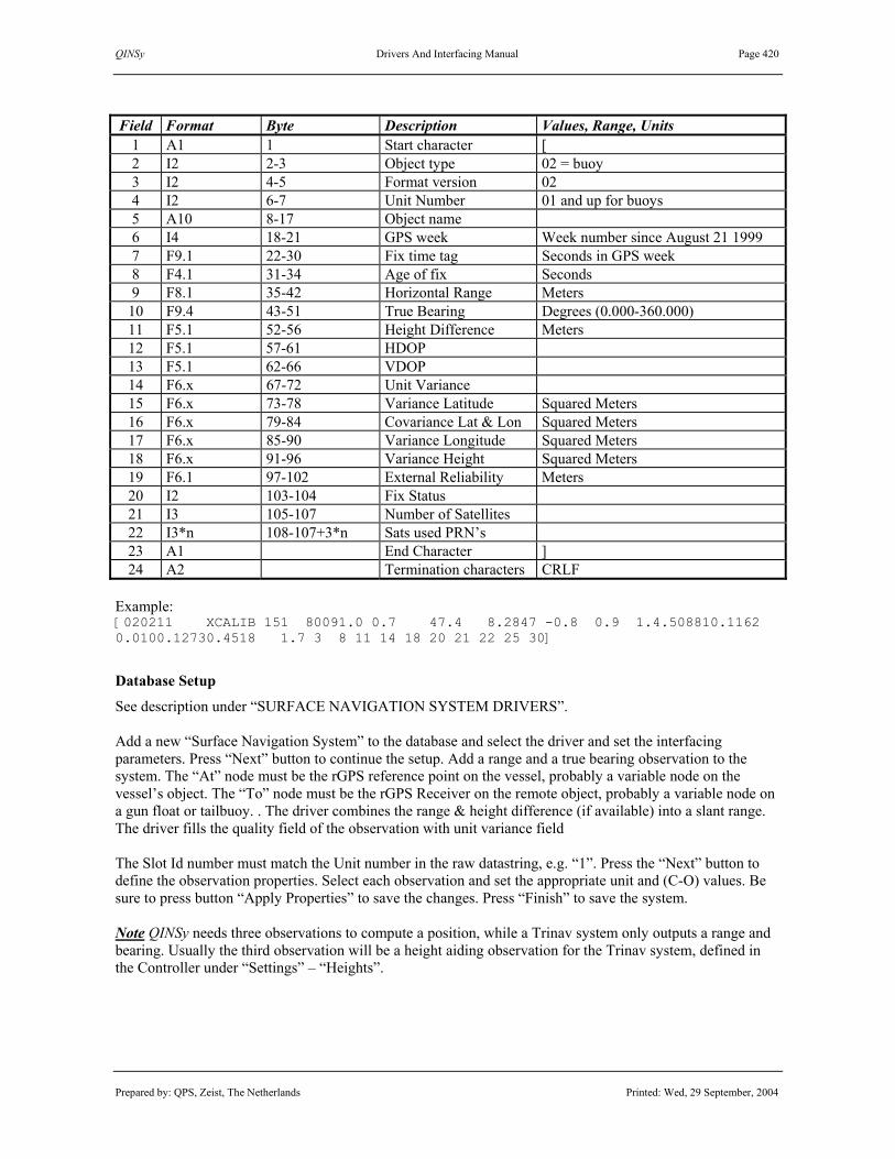
QINSy Drivers And Interfacing Manual Page 420
Prepared by: QPS, Zeist, The Netherlands Printed: Wed, 29 September, 2004
Field Format Byte Description Values, Range, Units
1 A1 1 Start character [ 2 I2 2-3 Object type 02 = buoy 3 I2 4-5 Format version 02 4 I2 6-7 Unit Number 01 and up for buoys 5 A10 8-17 Object name 6 I4 18-21 GPS week Week number since August 21 1999 7 F9.1 22-30 Fix time tag Seconds in GPS week 8 F4.1 31-34 Age of fix Seconds 9 F8.1 35-42 Horizontal Range Meters 10 F9.4 43-51 True Bearing Degrees (0.000-360.000) 11 F5.1 52-56 Height Difference Meters 12 F5.1 57-61 HDOP 13 F5.1 62-66 VDOP 14 F6.x 67-72 Unit Variance 15 F6.x 73-78 Variance Latitude Squared Meters 16 F6.x 79-84 Covariance Lat & Lon Squared Meters 17 F6.x 85-90 Variance Longitude Squared Meters 18 F6.x 91-96 Variance Height Squared Meters 19 F6.1 97-102 External Reliability Meters 20 I2 103-104 Fix Status 21 I3 105-107 Number of Satellites 22 I3*n 108-107+3*n Sats used PRN’s 23 A1 End Character ] 24 A2 Termination characters CRLF
Example: [020211 XCALIB 151 80091.0 0.7 47.4 8.2847 -0.8 0.9 1.4.508810.1162 0.0100.12730.4518 1.7 3 8 11 14 18 20 21 22 25 30]
Database Setup
See description under “SURFACE NAVIGATION SYSTEM DRIVERS”. Add a new “Surface Navigation System” to the database and select the driver and set the interfacing parameters. Press “Next” button to continue the setup. Add a range and a true bearing observation to the system. The “At” node must be the rGPS reference point on the vessel, probably a variable node on the vessel’s object. The “To” node must be the rGPS Receiver on the remote object, probably a variable node on a gun float or tailbuoy. . The driver combines the range & height difference (if available) into a slant range. The driver fills the quality field of the observation with unit variance field The Slot Id number must match the Unit number in the raw datastring, e.g. “1”. Press the “Next” button to define the observation properties. Select each observation and set the appropriate unit and (C-O) values. Be sure to press button “Apply Properties” to save the changes. Press “Finish” to save the system. Note QINSy needs three observations to compute a position, while a Trinav system only outputs a range and bearing. Usually the third observation will be a height aiding observation for the Trinav system, defined in the Controller under “Settings” – “Heights”.

QINSy Drivers And Interfacing Manual Page 421
Prepared by: QPS, Zeist, The Netherlands Printed: Wed, 29 September, 2004
3.15.16 NavAnalog Analog to Digital Converter Input / Output: Input Driver class type: Terminated <LF> Executable name: DrvNavAnalog.exe Drivers.io options: None Last modified: 2002-Jun-24
Driver Description
This driver can decode up to four analogue input voltages that are sent to QINSy by a NAVANALOG Analogue to Digital (RS232) converter. The Driver can decode voltages as raw observations but it can also be used to calculate the current bearing of an “AziPod” thruster by reading 2 analogue signals that represent the cosine and the sine of this bearing.
Format Description
This format is the default NAVANALOG A/D Converter output. Explanation of the fields: $ANLGa,bbbb, cccc,dddd,eeee*ff<CR><LF> $ANLG id of string a unit id [0..9] bbbb Voltage on Channel 1 (MilliVolts) [0..5000] cccc Voltage on Channel 2 (MilliVolts) [0..5000] dddd Voltage on Channel 3 (MilliVolts) [0..5000] eeee Voltage on Channel 4 (MilliVolts) [0..5000] ff Checksum Example: $ANLG1,3347,0033,1000,4999*EC Unit id is 1, Channel 1 is 3.347 Volts etc.
Database Setup
See description under “SURFACE NAVIGATION SYSTEM DRIVERS”. Add a “Surface Navigation System”, select system “NavAnalog Analog to Digital converter” and add up to four observations of any type. Generic aplications: Correct Scale Factor and Fixed C-O must be entered in DbSetup in order to convert to the correct value in other QINSy modules. Set the first slot number to indicate the channel of the A/D converter so fill in “1” for channel 1 etc. up to 4. Set the second slot number to “0”, this implicates it is a generic analogue observation. If the second slot number is not equal to zero, the driver will decode and process the analogue readings as an “AziPod” bearing. For AziPod Bearing: Select Observation of type “True Bearing” , Select “At Node” the node of the Thruster. Select for “To Node” any node you like (the “To Node” is not used). Select Degrees for units. Scale Factor and C-O’s can be given any value one finds appropriate. The field number in the input string for the Sine of the angle should be entered in slot1 (1..4). The field number in the input string for the Cosine of the angle should be entered in slot2 (1..4).

QINSy Drivers And Interfacing Manual Page 422
Prepared by: QPS, Zeist, The Netherlands Printed: Wed, 29 September, 2004
Example of setting up the scale factor and C-O: RPMs should be +160 when 5.0 Volts is decoded, -160 when 1.0 Volts is decoded. Scale Factor = 320 / 4 = 80.0 C- O = Obscalc / SF – Obsraw = 160 / 80 – 5.0 = -3.0.
Decoding notes
-Checksum is ignored. -For “AziPod” Bearing mode: Driver calculates an output angle between 0 – 360 degrees with hard coded scale factor and offset, presuming signals are interfaced with a 250 Ohms Resistor. -Analogue readings in output string are from 0-5000 milliVolts, These are internally converted to 0 to 5.0 Volts. -Driver does NOT use any conversions for generic analogue observations. It will decode the input voltage divide by 1000 as found in the string to convert from millivots to volts. -Unit id is ignored.
Interfacing Notes
AziPod: Every Azimuth Pod will provide three 4-20 mA analogue signals: 1) Sin(Angle) 4mA [-1] 20 mA [+1] 2) Cos(Angle) 4mA [-1] 20 mA [+1] 3) RPM 4mA[-160 Hz] 20 mA [+160 Hz] These signals should be connected through a 250 ohms 0.1% resistor to convert from Current to Voltage resulting in: 4mA - 1.0 Volts and 20mA – 5Volt. Generic: Input range of NavAnalog units is by default 0-5 volts.
Drivers.io Options
None.

QINSy Drivers And Interfacing Manual Page 423
Prepared by: QPS, Zeist, The Netherlands Printed: Wed, 29 September, 2004
3.15.17 ParkerPDFX Stepping Drive Driver Input / Output: Input (two-way) Driver class type: Terminated <LF> Executable name: DrvParkerPDFX.exe Drivers.io options: none Last modified: 2001-May-23
Driver Description
This is a driver for the Parker PDFX Series Mini Stepping Drive. It sends the command “1GOTO(MAIN)” to the controller when start recording is performed. It polls the driver every 0.1 second using the “1R(EP)” command for the current reading of the angle decoder. This angle is decoded and made available to the rest of QINSy. See below for the software that was downloaded in the drive.
Format Description
The drive responds to the “1R(EP)” command with the count from the angle decoder. The format is: *xxxxx<CR><LF>.
Field Format Description Values, Range, Units 1 * start of message 2 xxxxx decoder count counts 3 <CR><LF> end characters
Format Example *-5375<CR><LF>.
Decoding Notes
Data is decoded and passed on unscaled.
Interfacing Notes
The interface cable is a non-standard RS-232 two-way cable. See the diagram below for wiring details. Communication parameters are 19200 or 9600, 8, None, 1. Note that the echo switch must be ON.
DB-25 Sensor DB-9 COM DB-25 COM
Pin 4 RXD ----------------- Pin 3 TXD Pin 2 TXD Pin 5 TXD ----------------- Pin 2 RXD Pin 3 RXD Pin 3 SG ----------------- Pin 5 SG Pin 7 SG

QINSy Drivers And Interfacing Manual Page 424
Prepared by: QPS, Zeist, The Netherlands Printed: Wed, 29 September, 2004
Database Setup
Add an angle observation with the following properties to the system:
The scale factor is set up for a 20000 pulse per revolution encoder (400 / 20000 = 0.02).
Controller Setup
The motor will start and perform the main routine when the record command is received. Normally the main command will perform a single revolution, each time in an alternating direction. This is subject to the software in the motor drive.
Additional Information
See the following page for a list of the software that was uploaded to the PDFX drive.

QINSy Drivers And Interfacing Manual Page 425
Prepared by: QPS, Zeist, The Netherlands Printed: Wed, 29 September, 2004
1K 1CLEAR(ALL) 1START: 1DECLARE(MAIN) ;Declare Programs 1DECLARE(DATUM) 1OFF ;switch motor off 1W(MR,4000) ;Set motor resolution 1W(MC,70) ;Set motor current 1W(MS,50) ;Set standby current 1W(ER,400) ;Set encoder resolution 20000/50 1W(DU,1) ;Set to operate in encoder steps 1HOME1(+,0,+5.00,100.00,3) ;Set homing parameters 1LIMITS(3,1,0,200.0) ;Disable limits 1ON ;Turn motor on ;1GOSUB(DATUM) 1MI ;Motion Incremental 1D20000 ;Set distance for 360 degrees 1V1.00 ;Velocity 1VS0.25 1A250.00 1AD300.00 ;1LOOP(MAIN,0) 1END 1MAIN: ;Main program ;1R(EP) 1G ;Begin motion 1T0.50 ;Pause when motion complete 1H ;Change direction 1END 1DATUM: ;Homing routine 1W(CQ,0) ;Set for continuous execution mode 1O(1XXXXXXX) ;Turn output 1 on 1GH ;Go home 1T0.20 1O(0XXXXXXX) ;Turn output 1 off 1T0.20 1O(1XXXXXXX) ;Turn output 1 on 1T1.00 1TR(IP,=,1) ;Wait until motion has ceased 1W(PA,0) ;Set position to Zero 1W(CQ,1) ;Turn off continuous execution 1END 1ARM1 ;Run start program on power up 1SV Notes: 1. If the movement that occurs every time when record is performed, has to be changed, modify the
“1main:“ section of the program. Refer to the PDFX manual for available commands. 2. To start in a predefined position, execute the datum routine. This can be done in the following way:
a) Use a terminal program or, the Easi-tools to send the command ”1GOTO(DATUM) to the drive. b) Modify the above program. Uncomment the statement “;1GOSUB(DATUM)“ (remove the “;”
character). Now the motor will go to a predefined position every time the drive is powered on.

QINSy Drivers And Interfacing Manual Page 426
Prepared by: QPS, Zeist, The Netherlands Printed: Wed, 29 September, 2004
3.15.18 Simrad HPR LBL (Raw data)
Input / Output: Input Driver class type: Terminated <LF> Executable name: DrvSimradLBLRawData.exe Drivers.io options: none Last modified: 1998-Nov-11
Driver Description
Driver to decode Simrad HPR 400 LBL ranges, pitch & roll, course and depth in NMEA 0183 format.
Format Description
The LBL Position format is according to the “Standard NMEA 0183 Version 2.20”.
# Field Name Explanation 1 $ Start character 2 PSIMLBM Address Propr. Simrad address for LBL measurements. 3 ,hhmmss.ss Clock Clock in hours, minutes and seconds.
Decimal fraction is optional. 4 ,c—c Tp array Transponder array in which the measurements are done. 5 ,xx_ Td ID Identification of transducer on which reply is received. 6 ,x.x Roll Roll angle when receiving messages. 7 ,x.x Pitch Pitch angle when receiving messages. 8 ,x.x Course Course when receiving messages. 9 ,x.x Depth Fixed depth or depth received from a depth sensor.
Empty when no depth is available. 10 ,x.x Range 1 Range measured to the first location in the array.
Empty when no range measured. 11 ,x.x Range 2 Range to location 2 or empty. 12 ,x.x Range 3 Range to location 3 or empty. 13 ,x.x Range 4 Range to location 4 or empty. 14 ,x.x Range 5 Range to location 5 or empty. 15 ,x.x Range 6 Range to location 6 or empty. 16 ,x.x Range 7 Range to location 7 or empty. 17 ,x.x Range 8 Range to location 8 or empty. 18 ,aa_ Unit M when the ranges are in metres.
S when the ranges are in seconds. 19 *hh Checksum Empty or checksum. 20 CRLF Termination
Format Example $PSIMLBM,hhmmss.ss,c—c,xx_,x.x,x.x,x.x,x.x,x.x,x.x,x.x,x.x,x.x,x.x,x.x,x.x,aa_*hh<CRLF>
Decoding Notes
The QINSy driver only decodes the ranges in metres. (continued on next page)

QINSy Drivers And Interfacing Manual Page 427
Prepared by: QPS, Zeist, The Netherlands Printed: Wed, 29 September, 2004
Database Setup
See description under “SURFACE NAVIGATION SYSTEM DRIVERS”. To decode the ranges, add a “Fixed Node” with the correct positions for each of the seabed transponder used in the LBL array to the QINSy Database. Add the “Surface navigation system” and set the appropriate driver and interfacing parameters. In the observations tab, add “Range” observations connecting the LBL transducer and each of the seabed transponders in the array. For the slot numbers, apply the following convention. The observation between the LBL transducer and the first transponder (location) in the array will get slot number ‘1’, the observation between the LBL transducer and the second transponder will get slot number ‘2’, etc. To decode the pitch & roll, add a “Pitch, roll and heave sensor” and set the appropriate driver and interfacing parameters. The two observations are automatically added and connected to the system. Change parameters to match the rotation sign convention and measurement units of the format description. To decode the course, add a “System” of type “Gyro” and add an “Observation” of type “Bearing, true”. To decode the depth , add an “Observation” of type “ROV Depth” to the “Surface navigation system”. To decode all five observations, make sure to select the same driver name and I/O parameters for all systems.

QINSy Drivers And Interfacing Manual Page 428
Prepared by: QPS, Zeist, The Netherlands Printed: Wed, 29 September, 2004
3.15.19 Sonardyne PAN (SI/FS format)
3.15.20 Sonardyne PAN (LB format) Input / Output: Input Driver class type: Terminated <LF> Executable name: DrvSonardynePAN.exe Drivers.io options: LBL | FSS Last modified: 1999-Apr-25
Driver Description
This driver decodes LBL ranges from received from a PAN unit. It will decode ranges and depth FS, SI strings and ranges only from LB strings.
Format Description
The SI string contains the compatt id, compatt depth and ranges to transponders. SI1003S;1003;+ 182.0E 0; 2, 601.938 ; 3, 410.590 ; 4, 347.561 ; 5, 288.341 ; 6, 485.297 ; 7, 764.243 ; 8, 835.019 ; Explanation of the fields:
SI1003S; Source identifier 1003; Compatt identifier + 182.0E 0; Compatt depth 2, 601.938 ; individual reply frequency (IRF) and range in milliseconds
The LB strings looks like: LBL; 2, 453.715; 3, 367.370; 4, 324.744; 5, 439.538; 6, 391.931; 7, 477.689; 8, 300.736; Explanation of the fields:
LBL; String identifier 2, 453.715 ; individual reply frequency (IRF) and range in milliseconds.
Database Setup
See description under “SURFACE NAVIGATION SYSTEM DRIVERS”. Define a fixed node for each transponder used. Define a variable node on which the transducer or compatt is placed. Define an observation of type “Range” for each measured range. Remember to set the units of the range to milliseconds, to set the scale factor to 0.5 and to enter the propagation speed. If the FS/SI strings are used, then slot 1 must be set to the interrogating compatt id (e.g. in the string form the previous paragraph this is 1003). The second slot must be set to the Individual reply frequency (IRF) from the interrogated transponder. If the LBL string is used, only the IRF from the interrogated transponder has to be entered in the 1st slot. The IRFs can be found in the LBL array calibration report. (continued on next page)

QINSy Drivers And Interfacing Manual Page 429
Prepared by: QPS, Zeist, The Netherlands Printed: Wed, 29 September, 2004
Database Setup (continued)
Note on height or depth of ROV. Normally the transponders are located nearly in a plane so the observations do not contain enough information to solve for the height component of the ROV position. To make the computation calculate the height, it needs extra height information. Defining a height aiding value can provide this. This is done by checking the height aiding box on the first tab of the system property dialog in the DbSetup program. During a replay or online session this displays a height-aiding driver. If no online information is present, select the manual option from the ROV depth box and enter the depth of the ROV manually. In the case of FS/SI strings the height received from the compatt can be used: Define an “ROV Depth” observation at the ROV compatt node and connect this observation to the PAN system. During online or replay this observation will be filled with the depth from the SI string, and can be selected in the ROV depth box.

QINSy Drivers And Interfacing Manual Page 430
Prepared by: QPS, Zeist, The Netherlands Printed: Wed, 29 September, 2004
3.15.21 WAGO Dynamic Transducer Mounting Input / Output: Input Driver class type: Terminated <LF> Executable name: DrvWAGODynaMount.exe Drivers.io options: MM | Custom Last modified: 2002-May-16 Frame definition
Driver Description
Driver is used for calculating the offset mounting angle of a rotation frame on which a Multibeam transducer is mounted. The frame is constructed in such a way that the transducer rotates around it’s acoustic centre. This driver decodes a hydraulic cylinder displacement (range) and a vertical offset that is sent by the “WAGO” unit (via the WAGO stand alone program). With the displacement and three fixed, frame dependant parameters; it calculates a vertical, roll-offset angle. The Roll Offset angle is 0 when the transducer points downwards along the Z-axis of the vessels reference frame, and is 90 degrees when transducers’ Nadir beam points horizontal.
Format Description
The WAGO software outputs the vertical offset and cylinder displacement in micrometers. Warning, older WAGO software versions may output in 1/10 of millimetres. In order to cope with these units, add command line parameter “MM” in Drivers.io file. $WAGO, C, V $WAGO id of string C cylinder displacement in micrometers, length variable, range 0 – 74 mm V vertical offset of mounting frame, length variable Example: $WAGO,74000,1160900 $WAGO,0,0 $WAGO,0,16900
Database Setup
See description under “SURFACE NAVIGATION SYSTEM DRIVERS”. Add a “Surface Navigation System”, select system “Wago Dynamic Transducer Mounting” and add two obsevations:
1) Observation of type “Angle” , Select “At Node” the node of the Multibeam transducer. Select for “To Node” any node you like (the “To Node” is not used). The driver outputs the angle in the unit that is selected on the next page, degrees will ususally suffice. note: type of observation must be angle, otherwise it can not beassigned as a MBE Head Dynamic Alignment Observation The calculated angle is added to the corresponding mounting offset angle in the QINSy “Multibeamer” component. Therefor for example, a positve roll angle observation will be interpreted as the frame rotating clockwise along the +Forward Axis (looking from aft to bow). By applying a Scale factor of –1 to the Anlge observation properties, one can compensate for the fact that the calculated angle sign is opposite of the default Roll convention (positve Roll -> starboard down).
2) Observation of type Range, Select any “At” and “To” nodes.

QINSy Drivers And Interfacing Manual Page 431
Prepared by: QPS, Zeist, The Netherlands Printed: Wed, 29 September, 2004
After Observations are defined , the angle observation must be assigned in the MBE Setup Pages as a MBE Head Dynamic Alignment Observation. Refer to “MULTIBEAM ECHOSOUNDER SYSTEM DRIVERS” chapter for more information.
Drivers.io Options
MM: If parameter MM is entered in drivers.io then driver will decode the found values as being 1/10 of a millimetre instead of the default micrometers. Frame Parameters: The frame parameters are hard-coded into the driver as: A: 98 mm B: 413 mm C: 350 mm By default these are used, that is if no extra parameters are found in driver.io. However it is possible to enter custom parameters in drivers.io as command line parameters following the executable name. The order is crucial, it should be: Driversname.exe <SPACE> A <SPACE> B <SPACE> C <SPACE> MM (optional) Example for the default parameters with decoding in micrometers: DrvWAGODynaMount.exe 98 413 350 note: The values must be entered in millimeters.

QINSy Drivers And Interfacing Manual Page 432
Prepared by: QPS, Zeist, The Netherlands Printed: Wed, 29 September, 2004
(This page intentionally left blank)

QINSy Drivers And Interfacing Manual Page 433
Prepared by: QPS, Zeist, The Netherlands Printed: Wed, 29 September, 2004
3.16 SATELLITE NAVIGATION SYSTEM DRIVERS
Database Setup
First define and select the “Object” on which the GPS antenna is located. Select item “Systems” and define a new “Satellite navigation system”. Select the appropriate driver and interface parameters. It is recommended to set the baud rate as high as possible (and leave the update rate and latency at 0 seconds). Press the “Next” button to complete the setup. There is no need to define the (32) pseudo-range observations separately, since they are automatically added to the system. If wanted, change name and a priori SD for the PR observations. Select object and node for the GPS antenna. Press “Finish” button to save system. See example below.

QINSy Drivers And Interfacing Manual Page 434
Prepared by: QPS, Zeist, The Netherlands Printed: Wed, 29 September, 2004
Database Setup (continued)
A new antenna node can be added by pressing the button; to change its properties, press the button.
See for more information the QINSy DB Setup Help Topics or the QINSy Knowledge Base.

QINSy Drivers And Interfacing Manual Page 435
Prepared by: QPS, Zeist, The Netherlands Printed: Wed, 29 September, 2004
3.16.1 Aquarius (Port A)
3.16.2 Aquarius (Port B) Input / Output: Input (two-way) Driver class type: Terminated <ETX> Executable name: DrvAquarius.exe Drivers.io options: A | B Last modified: 2003-Dec-10
Driver Description
Driver to be used to obtain raw GPS pseudo-ranges and various GPS broadcast data (as well as differential corrections) from a Aquarius2 GPS receiver (Thales Ashtech DSNP Sercel).
System Configuration
Aquarius2 GPS receivers have four ports (A, B, C and D) and one auxiliary (AUX) port. The AUX port is used for the PPS signal. Port A or B must be configured to output the raw GPS data (SVAR!R, SVAR!D, SVAR!E and SVAR!U messages). No other messages should be outputted. Easiest is to connect to port B, because this is the only RS232 port on the receiver’s rear panel. It is advisable to have the interfacing two-way, so the driver will send commands to the receiver asking for ephemeredes, iono and UTC parameters. Therefor it is important to select the right driver, Aquarius (Port A) or Aquarius (Port B). If the interfacing is not two-way and you go on-line, it may take more than half a hour before before a GPS solution can be calculated, d/t missing ephemeredes.
Format Description
Four types of messages will be decoded: SVAR!R (Raw Ranges), SVAR!D (Differential Corrections), SVAR!E (Ephemerides) and SVAR!U (Iono and UTC parameters) All messages are in hexadecimal values represented in ASCII format. See for a detailed description of the message the Ashtech Aquarius2 User Manual.

QINSy Drivers And Interfacing Manual Page 436
Prepared by: QPS, Zeist, The Netherlands Printed: Wed, 29 September, 2004
AUX, Port A and Port B connector at the rear panel of the Aquarius2 GPS receiver.

QINSy Drivers And Interfacing Manual Page 437
Prepared by: QPS, Zeist, The Netherlands Printed: Wed, 29 September, 2004
3.16.3 Ashtech ADU2 [old version] Input / Output: Input (two-way) Driver class type: Terminated <LF> Executable name: DrvAshtechADU2.exe Drivers.io options: A | B | filename Last modified: 1997-May-01
Driver Description
Driver for Ashtech ADU2 GPS receiver, Driver used to obtain raw GPS pseudo-ranges and GPS ephemeris data from the GPS receiver. Driver can also be used to decode positions, attitude and heading data that is outputted by the Ashtech ADU2 GPS receiver in Ashtech (ASCII or binary) raw data message format.
Format Description
The Ashtech $PASHQ/$PASHR protocols define query commands and (partly binary) responses to be used by a computer to control and interrogate Ashtech receivers. See Ashtech manuals for more information.
System Configuration
Raw data parameter settings commands are controlled by the QINSy Ashtech ADU2 driver. The driver uses the file “DrvAshtechADU2.txt” located in the QINSy program directory, for example “C:\Program Files\QPS\QINSy 70\”. Most vessels most likely will require changes in the antenna vector settings and the C-O values ($PASHS,3DF). !!! BE SURE TO CHECK THIS FILE BEFORE USING THE QINSy Ashtech ADU2 DRIVER !!! One can also use a utility program to communicate directly with an Ashtech GPS receiver, such as QINSy IO Test or HyperTerminal under Windows, or Procomm Plus under MS-DOS. All command messages (set, query or general) must be all UPPER CASE and completed by <CR><LF>. A valid set command ($PASHS) causes the ADU2 to return the $PASHR,ACK*3D, acknowledged message. Unrecognized commands cause the $PASHR,NAK*30, not-acknowledged response message. Valid queries return the requested data. Query receiver options: $PASHQ,RID<CR><LF> Query general parameters: $PASHQ,PAR<CR><LF> Query differential parameters: $PASHQ,RTC<CR><LF> Query 3DF ADU parameters: $PASHQ,3DF<CR><LF> Query port and baud rate: $PASHQ,PRT<CR><LF> Set baud rate on port x : $PASHS,SPD,x,s<CR><LF> where 5=9600, 6=19200, 7=38400, 8=56800, 9=115200 baud Set raw data output interval: $PASHS,RCI,x.x<CR><LF> Set all data/NMEA strings off: $PASHS,NME,ALL,x,OFF<CR><LF> Set raw data/NMEA string off: $PASHS,NME,str,x,OFF<CR><LF> Set raw data/NMEA string on: $PASHS,NME,str,x,ON<CR><LF> Output pseudo ranges (binary): $PASHS,OUT,x,MBN,BIN<CR><LF> Output attitude info (binary): $PASHS,OUT,x,ATT,BIN<CR><LF> Output ephemerides (binary): $PASHS,OUT,x,SNV,BIN<CR><LF> See also the description of the ResetAshtech utility on the next page.

QINSy Drivers And Interfacing Manual Page 438
Prepared by: QPS, Zeist, The Netherlands Printed: Wed, 29 September, 2004
Format Description
The Ashtech $PASHQ/$PASHR protocols define query commands and (partly binary) responses to be used by a computer to control and interrogate Ashtech receivers. See Ashtech manuals for more information.
Database Setup
See description under “SATELLITE NAVIGATION SYSTEM DRIVERS”.
Drivers.io Options
Command line parameter A or B indicates the COM port to which the QINSy driver is connected. A filename can be added after the port parameter, if the setup file is not the default “DrvAshtechADU2.txt” file.
Driver Utility
The “ResetAshtech“ utility is necessary if the hardware reset on the Ashtech ADU2 receiver is used. After this reset has been pressed, but before QINSy is started, double-click the “Reset Ashtech” icon. This will upload a file to the ADU2, which will set port A of the receiver to a higher baud rate than the usual 9600. If no “Reset Ashtech” icon is available on the desktop, create a shortcut to this utility as is described below. The ResetAshtech utility sends a file over a COM port to the ADU2. The COM parameters are 9600 baud, 8 databits, 1 stopbit and NO parity, and can not be altered. The program accepts two optional arguments: ResetAshtech [com [file]] com COM port number to be used; default is COM 1; file filename of the file to be uploaded to the ADU2; default is “ResetAshtech.txt”. The utility can be executed by selecting the “Run…” option in the Start menu in the Windows NT taskbar, by entering the following command, “C:\Program Files\QPS\QINSy 70\ResetAshtech.exe” if above mentioned defaults can be used, or “C:\ Program Files\QPS\QINSy 70\ResetAshtech.exe n filename”, where “n” is the COM port to which the Ashtech receiver is connected and “filename” is the file to be uploaded. The file should contain the line “$PASHS,SPD,x,d”, where “x” is the serial port (A or B), and “d” is the baud rate (5 = 9600, 6 = 19200, 7 = 38400, etcetera). A shortcut to ResetAshtech.exe can be created (under the Explorer or on the desktop), and put in directory “\Winnt\Profiles\All Users\Desktop\”, if the icon has to show up on every desktop, or in the directory “\Winnt\Profiles\Peter\Desktop\”, if the icon has to show up on the desktop of a single user only. The command line arguments for ResetAshtech can be modified by clicking the shortcut icon, and selecting “Properties” – “Shortcut” – “Target”. Also pay attention to the “Start in” line and the “Change icon” button. Note. If the default “DrvAshtechADU2.txt” setup file is used and the baud rate should not be reset to 9600, comment out the line to reset the receiver to defaults, i.e. change “$PASHS,RST” to “// $PASHS,RST”.

QINSy Drivers And Interfacing Manual Page 439
Prepared by: QPS, Zeist, The Netherlands Printed: Wed, 29 September, 2004
3.16.4 Ashtech ADU2 Raw Data
3.16.5 Ashtech G12 GPS Board Input / Output: Input (two-way) Driver class type: Terminated <LF> Executable name: DrvAshtech.exe Drivers.io options: ADU2 | G12 | Z12 Last modified: 2004-Apr-26 A | B | C | NOCS
Driver Description
Driver for Ashtech GPS board and receivers, which output raw data compatible with ADU2, G12 or Z12. Driver to be used to obtain raw GPS pseudo-ranges and GPS broadcast data from the GPS receiver board. The Ashtech ADU2 driver can also decode positions (PBEN/PSAT) and/or attitude data (ATTD/PSAT). The driver also supports a setup file to configure an Ashtech receiver or GPS board, see details below.
Format Description
The Ashtech $PASHQ/$PASHR protocols define query commands and (partly binary) responses to be used by a computer to control and interrogate Ashtech receivers. See Ashtech manuals for more information. The following raw data messages are decoded by the Ashtech G12/Z12 drivers: MCA, MPC, SNV, ION. The Ashtech ADU2 driver will decode the MCA, MPC, SNV, ION, plus the PBN, ATT, PSA messages.
Drivers.io Options
Required command line parameter for using DrvAshtech for ADU2 GPS receivers, including the options to decode positions (PBEN/PSAT) and/or attitude data (ATTD/PSAT) is “ADU2”. Required command line parameter for using DrvAshtech for G12 GPS boards and G12 compatible GPS receivers (e.g. DG14 and DG16) is “G12”. Required command line parameter for using DrvAshtech for Z12 receivers is “Z12”. The command line parameter “A”, “B” or “C” is the port designator for the raw data message output. Add “NOCS” to the Ashtech driver command lines in Drivers.io to skip the checksum computations.
Interfacing Notes
It is important that the wiring of the cable between the Ashtech board and the COM port is bi-directional, i.e. allows two-way data transfer, so that the QINSy driver can control and interrogate the GPS receiver/board.
System Configuration
To communicate with an Ashtech receiver or GPS board, use a utility program such as the QINSy utility IO Tester or HyperTerminal under Windows or PROCOMM PLUS under MS-DOS. Command messages (set, query or general) must be all UPPER CASE and completed by <CR><LF>. A valid set command ($PASHS) causes Ashtech recievers to return the $PASHR,ACK*3D acknowledged message. Unrecognised commands cause the $PASHR,NAK*30, not-acknowledged response message. Valid queries return the requested data. For GPS receivers using an Ashtech G12 GPS board, see the appropriate manufacterer’s manuals. To give an example, in configuring the GBX PRO combined GPS/Beacon Receiver from Communication Systems International (C.S.I.) Inc., put the selector switch on the rear panel to GPS (or NORM), to communicate with the Ashtech G12 GPS receiver inside the GBX PRO using for example the QINSy IO Test Utility. $PASHS,RST<CR><LF> : Reset all parameters to their default values $PASHS,SAV,Y<CR><LF> : Set save parameters to enabled (until RST)

QINSy Drivers And Interfacing Manual Page 440
Prepared by: QPS, Zeist, The Netherlands Printed: Wed, 29 September, 2004
DrvAshtechADU2.txt For the Ashtech ADU2 driver, if the file “DrvAshtechADU2.txt” is found in the QINSy setup directory, the non-comment lines in this file (i.e. lines not starting with “//”) will be sent to the Ashtech receiver upon startup (and when resetting the driver). Create an empty setup file in order to suppress sending commands. If the “DrvAshtechADU2.txt” file is not found, the following set of commands is sent by the driver, where ‘A’ is the port for the message output and is replaced by ‘B’ depending on the selected driver: // Set recording interval $PASHS,ONE,Y $PASHS,RCI,1 // Set minimum elevation $PASHS,ELM,0 // Set minimum number of SV's $PASHS,MSV,0 // Turn ON filtering of attitude data $PASHS,3DF,FLT,Y // Reset kalman filters used for attitude computations $PASHS,3DF,RST // Turn OFF all output $PASHS,OUT,A // Turn ON output of following records (all in binary) // MBN = Measurement Data // SNV = Ephemerides Data // ATT = Attitude Data (We need one of these for // PBN = Position Data the GPS time contruction) $PASHS,OUT,A,MBN,SNV,PBN,ATT,BIN // Ask for ephemerides $PASHQ,SNV DrvAshtechG12.txt For the Ashtech type G12 driver, if the file “DrvAshtechG12.txt” is found in the QINSy setup directory, the non-comment lines in this file (i.e. lines not starting with “//”) will be sent to the Ashtech receiver upon startup (and when resetting the driver). Create an empty setup file in order to suppress sending commands. If the “DrvAshtechG12.txt” file is not found, the following set of commands is sent by the driver, where ‘A’ is the port for the message output and is replaced by ‘B’ depending on selected driver: // Set recording interval $PASHS,RCI,1 // Set minimum elevation $PASHS,ELM,0 // Set minimum number of SV's $PASHS,MSV,0 // Ask for ionospheric parameters $PASHQ,ION,A // Turn OFF all NMEA output records $PASHS,NME,ALL,A,OFF // Turn OFF all raw output records $PASHS,RAW,ALL,A,OFF // Turn ON output ephemerides $PASHS,RAW,SNV,A,ON // Turn ON output of C/A pseudo ranges $PASHS,RAW,MCA,A,ON // Ask for ephemerides $PASHQ,SNV

QINSy Drivers And Interfacing Manual Page 441
Prepared by: QPS, Zeist, The Netherlands Printed: Wed, 29 September, 2004
CONFIGURING GBX PRO FOR (INTERNAL) USE OF RTCM DIFFERENTIAL CORRECTIONS When reset, the GPS receiver does not communicate with the Beacon receiver. Set and check: $PASHS,RTC,REM,B<CR><LF> : Set receiver as differential remote using port B (!!!) $PASHS,RTC,AUT,N<CR><LF> : Set auto differential mode to disabled (Y : enabled) $PASHS,RTC,MAX,x<CR><LF> : Set maximum age of corrections to x seconds $PASHQ,RTC<CR><LF> : Query differential parameters : MODE:REM PORT:B CONFIGURING GBX PRO FOR NMEA OUTPUT OF (INTERNAL) GPS POSITION RESULTS See G12 Reference Manual for (default) receiver commands. Give non-default settings commands: $PASHS,ALT,x<CR><LF> : Set 2D position ellipsoidal antenna height to x metres $PASHS,ION,Y<CR><LF> : Set ionospheric model to be included (N : excluded) $PASHS,NME,PER,x<CR><LF> : Set send interval of response message to x seconds $PASHS,NME,GGA,A,ON<CR><LF> : Set GGA message on port A to enabled $PASHQ,PAR<CR><LF> : Query general parameters : RTC:REM PRT:B $PASHQ,PRT<CR><LF> : Query connected serial port baud rate : A,x CONFIGURE GBX PRO FOR OTHER BAUD RATE THAN DEFAULT 9600 BAUD SETTINGS Possible G12 baud rate codes for QINSy are 5=9600, 6=19200, 7=38400, 8=56800. Set and check: $PASHS,SPD,A,x<CR><LF> : Set baud rate of G12 serial port A to x $PASHQ,PRT<CR><LF> : Query connected serial port baud rate : A,x
Database Setup
See general description under “SATELLITE NAVIGATION SYSTEM DRIVERS”. The Ashtech ADU2 driver can also decode positions (PBEN/PSAT) and/or attitude data (ATTD/PSAT). See general descriptions under “POSITION NAVIGATION SYSTEM DRIVERS”, “GYRO’S AND COMPASSES SYSTEM DRIVERS” and/or “PITCH, ROLL AND HEAVE SENSOR DRIVERS”. Make sure to select the same driver name (COM port) and the same I/O parameters for all systems.

QINSy Drivers And Interfacing Manual Page 442
Prepared by: QPS, Zeist, The Netherlands Printed: Wed, 29 September, 2004
3.16.6 Ashtech Z12 Raw Data Input / Output: Input (two-way) Driver class type: Terminated <LF> Executable name: DrvAshtech.exe Drivers.io options: ADU2 | G12 | Z12 Last modified: 2004-Apr-26 A | B | C | NOCS
Driver Description
Driver for Ashtech Z12 GPS receiver. Driver to be used to obtain raw GPS pseudo-ranges and various GPS broadcast data from the GPS receiver. At present, the (binary) position data messages are not decoded.
Format Description
The Ashtech $PASHQ/$PASHR protocols define query commands and (partly binary) responses to be used by a computer to control and interrogate Ashtech receivers. See Ashtech manuals for more information.
System Configuration
The Ashtech Z12 GPS receiver can be configured for use by QINSy by using the Screen 4 Mode Control. INTERVAL [001.0] defines output rate of real-time MBEN (measurement) files; MIN SVS [3] as well as ELEV MASK [00°] influence number of sent MBEN files. SNAV (ephemeris data) files are to be output every 15 minutes [default]. PORT A/B (whichever is connected to the PC) must be configured as follows: NMEA OFF BAUD RATE nnnnn (as high as possible) REAL TIME ON Options (MEASUREMENTS OUTPUT ON PORT A/B) should be configured as follows: MBEN ON BINARY format PBEN OFF DBEN OFF SNAV ON EPB OFF SALM OFF RS-232 cable with 09-pin connection can be configured for handshake by connecting 7 RTS and 8 CTS; RS-232 cable with 25-pin connection can be configured for handshake by connecting 4 RTS and 5 CTS.
Interfacing Notes
It is important that the wiring of the cable between the Ashtech Z12 and the COM port is bi-directional, i.e. allows two-way data transfer, so that the QINSy driver can request new ephemerides from the receiver.
Database Setup
See description under “SATELLITE NAVIGATION SYSTEM DRIVERS”.
Drivers.io Options
Required command line parameter for using DrvAshtech for Ashtech Z12 receivers is “Z12”.

QINSy Drivers And Interfacing Manual Page 443
Prepared by: QPS, Zeist, The Netherlands Printed: Wed, 29 September, 2004
3.16.7 Leica MX 9400N (Active Raw Data) Input / Output: Input (two-way) Driver class type: Terminated <LF> Executable name: DrvMagnavox.exe Drivers.io options: ACTIVE 9400 Last modified: 1998-Aug-06
Driver Description
Driver for Leica MX 9400N receiver. Driver to be used to obtain raw GPS pseudo-ranges and GPS broadcast data in compressed measurement format. The active mode of the Leica MX 9400N driver switches off all output on the control port, redirects the raw data port to the control port, switches on the record type mentioned above, and asks for ephemerides.
Format Description
The receiver outputs the raw data record type 3 (compressed measurement data) and types 200-203 (satellite ephemeris data). For use with the Magnavox PPS driver, output sequence $PMVGG,830 is also needed.
System Configuration
The Leica MX 9400N receiver can be configured using the “CDU” program as follows. • Receiver Port Config: Set the interface parameters for the receiver. QPS advises 19200 or as high as
possible, 8, N, 1 for port 1 (CDU port).
Interfacing Notes
The cable between the Leica multiport interface cable CDU port 1 and the PC serial COM port must be:
DB-25 CDU Port DB-9 COM DB-25 COM Pin 2 RXD ----------------- Pin 3 TXD Pin 2 TXD Pin 3 TXD ----------------- Pin 2 RXD Pin 3 RXD Pin 7 SG ----------------- Pin 5 SG Pin 7 SG
Alternatively the PC serial COM port can be connected directly to the multiport interface connector:
DB-25 MultiPort DB-9 COM DB-25 COM Pin 10 RXD ----------------- Pin 3 TXD Pin 2 TXD Pin 11 TXD ----------------- Pin 2 RXD Pin 3 RXD Pin 24 SG ----------------- Pin 5 SG Pin 7 SG
Database Setup
See description under “SATELLITE NAVIGATION SYSTEM DRIVERS”.
Drivers.io Options
Required command line parameters for using DrvMagnavox for these receiver options are “ACTIVE 9400”.

QINSy Drivers And Interfacing Manual Page 444
Prepared by: QPS, Zeist, The Netherlands Printed: Wed, 29 September, 2004
3.16.8 Leica MX 9400N (Passive Raw Data) Input / Output: Input (one-way) Driver class type: Terminated <LF> Executable name: DrvMagnavox.exe Drivers.io options: RAW 9400 Last modified: 1998-Aug-06
Driver Description
Driver for Leica MX 9400N receiver. Driver to be used to obtain raw GPS pseudo-ranges and GPS broadcast data in compressed measurement format. The same driver can also be used to decode (computed or predicted) positions, output by the Leica MX 9400N receiver in proprietary NMEA sentence format.
Format Description
The Leica proprietary NMEA sentence format always start with the “$PMVXG” label, followed by the sentence type, consisting of three decimal digits, the data string, the (optional) checksum, and <CR><LF>. The “$PMVXG,021” output sentence contains the computed position, height, velocity and navigation mode; the “$PMVXG,121” output sentence contains the predicted position, height, velocity and navigation mode, within a few milliseconds of measurement receipt time, synchronised to the 1PPS output. The measurements currently received are used in the fix computation found in the type “021” and “023” sentences, and will be extrapolated forward to produce the ‘predicted’ position found in the type “121” and “123” sentences.
System Configuration
The Leica MX 9400N receiver can be configured for raw data output using the “CDU” program as follows. • Receiver Port Config: Set the interface parameters for the receiver. QPS advises 19200 or as high as
possible, 8, N, 1 for port 1 (CDU port). • Receiver Port Assign: Control port = 1, Raw Data port = 1, RTCM port = 3, Equipment port = None. • Receiver Raw Data Control: Nav Results = Off Raw Measurements = Compressed Type 3 Almanac / Ephemerides = Yes Constellation = No Differential = Off External Event = 0000 Beacon Receiver = No Time Recovery = No Full Debug = No Partial Debug = 0000 The Leica MX 9400N receiver can be configured for position output using the “CDU” program as follows. • Receiver Port Config: Set the interface parameters for the receiver. QPS advises 19200 or as high as
possible, 8, N, 1 for port 1 (CDU port) and port 2. • Receiver Port Assign: Control port = 1, Raw Data port = 1, RTCM port = 3, Equipment port = 2. • NMEA Message Control: Port = Equipment Message ID = 021 (Computed Position) Interval = 1 sec Select Add To List, press Enter. NMEA computed positions are now output to port 2. (continued on next page)

QINSy Drivers And Interfacing Manual Page 445
Prepared by: QPS, Zeist, The Netherlands Printed: Wed, 29 September, 2004
Interfacing Notes
The cable between the Leica multiport interface cable CDU port 1 and the PC serial COM port must be:
DB-25 CDU Port DB-9 COM DB-25 COM Pin 3 TXD ----------------- Pin 2 RXD Pin 3 RXD Pin 7 SG ----------------- Pin 5 SG Pin 7 SG
Alternatively the PC serial COM port can be connected directly to the multiport interface connector:
DB-25 MultiPort DB-9 COM DB-25 COM Pin 11 TXD ----------------- Pin 2 RXD Pin 3 RXD Pin 24 SG ----------------- Pin 5 SG Pin 7 SG
Database Setup
See description under “SATELLITE NAVIGATION SYSTEM DRIVERS”.
Drivers.io Options
Required command line parameters for using DrvMagnavox for these receiver options are “RAW 9400”.

QINSy Drivers And Interfacing Manual Page 446
Prepared by: QPS, Zeist, The Netherlands Printed: Wed, 29 September, 2004
3.16.9 Magnavox 9212 (Active Raw Data) Input / Output: Input (two-way) Driver class type: Terminated <LF> Executable name: DrvMagnavox.exe Drivers.io options: ACTIVE Last modified: 1997-Sep-08
Driver Description
Driver for Magnavox 9212 DGPS Navigator. Driver to be used to obtain raw GPS pseudo-ranges and GPS broadcast data in compressed measurement format. The active mode of the Magnavox 9212 driver switches off all output on the control port, redirects the raw data port to the control port, switches on the record type mentioned above, and asks for ephemerides.
Format Description
The receiver outputs the raw data record type 3 (compressed measurement data) and types 200-203 (satellite ephemeris data). For use with the Magnavox PPS driver, output sequence $PMVGG,830 is also needed.
Interfacing Notes
The cable between the Magnavox multiport interface cable CDU port 1 and the PC serial COM port must be:
DB-25 CDU Port DB-9 COM DB-25 COM Pin 2 RXD ----------------- Pin 3 TXD Pin 2 TXD Pin 3 TXD ----------------- Pin 2 RXD Pin 3 RXD Pin 7 SG ----------------- Pin 5 SG Pin 7 SG
Alternatively the PC serial COM port can be connected directly to the multiport interface connector:
DB-25 MultiPort DB-9 COM DB-25 COM Pin 10 RXD ----------------- Pin 3 TXD Pin 2 TXD Pin 11 TXD ----------------- Pin 2 RXD Pin 3 RXD Pin 24 SG ----------------- Pin 5 SG Pin 7 SG
Database Setup
See description under “SATELLITE NAVIGATION SYSTEM DRIVERS”.
Drivers.io Options
Required command line parameter for using DrvMagnavox for these receiver options is “ACTIVE”.

QINSy Drivers And Interfacing Manual Page 447
Prepared by: QPS, Zeist, The Netherlands Printed: Wed, 29 September, 2004
3.16.10 Magnavox 9212 (Passive Raw Data) Input / Output: Input (one-way) Driver class type: Terminated <LF> Executable name: DrvMagnavox.exe Drivers.io options: RAW Last modified: 1997-May-01
Driver Description
Driver for Magnavox 9212 DGPS Navigator. Driver to be used to obtain raw GPS pseudo-ranges and GPS broadcast data in compressed measurement format. The same driver can also be used to decode (computed or predicted) positions, output by the Magnavox 9212 GPS receiver in proprietary NMEA sentence format.
Format Description
The Magnavox proprietary NMEA sentence format always start with the “$PMVXG” label, followed by the sentence type, consisting of three decimal digits, the data string, the (optional) checksum, and <CR><LF>. The “$PMVXG,021” output sentence contains the computed position, height, velocity and navigation mode; the “$PMVXG,121” output sentence contains the predicted position, height, velocity and navigation mode, within a few milliseconds of measurement receipt time, synchronised to the 1PPS output. The measurements currently received are used in the fix computation found in the type “021” and “023” sentences, and will be extrapolated forward to produce the ‘predicted’ position found in the type “121” and “123” sentences.
Interfacing Notes
The cable between the Magnavox multiport interface cable CDU port 1 and the PC serial COM port must be:
DB-25 CDU Port DB-9 COM DB-25 COM Pin 3 TXD ----------------- Pin 2 RXD Pin 3 RXD Pin 7 SG ----------------- Pin 5 SG Pin 7 SG
Alternatively the PC serial COM port can be connected directly to the multiport interface connector:
DB-25 MultiPort DB-9 COM DB-25 COM Pin 11 TXD ----------------- Pin 2 RXD Pin 3 RXD Pin 24 SG ----------------- Pin 5 SG Pin 7 SG
Database Setup
See description under “SATELLITE NAVIGATION SYSTEM DRIVERS”.
Drivers.io Options
Required command line parameter for using DrvMagnavox for these receiver options is “RAW”.

QINSy Drivers And Interfacing Manual Page 448
Prepared by: QPS, Zeist, The Netherlands Printed: Wed, 29 September, 2004
3.16.11 Sercel NR103 (Passive Raw Data) Input / Output: Input (two-way) Driver class type: Terminated <ETX> Executable name: DrvNR103.exe Drivers.io options: none Last modified: 1998-Aug-19
Driver Description
Driver for Sercel NR103 and NR203. Driver to be used to obtain raw GPS pseudo-ranges and various GPS broadcast data (as well as differential corrections) from a Sercel NR103 or NR203 series GPS receiver.
System Configuration
To configure Sercel NR103 receivers, use the AUX and INIT menus. The following description defines only the essential settings; those not shown are not important to the operation of the QINSy system. QPS strongly recommends to interface to port A for the auxiliary position and to port B for the raw GPS output data.
• Use the AUX menu to set the RS 232 parameters: QPS recommends : Baudrate 19200 (or as high as possible) Databits 8 Parity N Stopbits 1
• Use the INIT menu to select the port messages: Port A Messages : A1, A2, A3 ON, 1 sec update All other messages on port A, as well as the raw data output should be switched off. Port B Raw Data : CDAT, DGPS, SMEAS, (In case a HF station has been SYNCH 600s 2*0.6 sec. selected on the receiver.) or : CDAT, NONE, SMEAS, (In case no HF but a RTCM SYNCH 600s 2*0.6 sec. station has been selected.) All B-messages should be switched off.
• Switch on the following messages in case you are using a NR103 only for retrieving HF corrections: Port A or B Raw Data : CDAT, DGPS, OFF, SYNCH 600s 2*0.6 sec.
(continued on next page)

QINSy Drivers And Interfacing Manual Page 449
Prepared by: QPS, Zeist, The Netherlands Printed: Wed, 29 September, 2004
Interfacing Notes
It is important that the wiring is bi-directional. Every time QINSy needs ephemerides (e.g. at initialisation), it will ask the receiver for it. This also applies to the case where only corrections are read from the receiver. Therefore, the wiring of the 9-pin port A or port B of the NR103 receiver to a 9-pin or 25-pin multiple COM interface board (e.g. Digi 8e) must be as follows:
DB-9 NR103 DB-9 COM DB-25 COM Pin 2 TXD ---------------------- Pin 2 RXD Pin 3 RXD Pin 3 RXD ---------------------- Pin 3 TXD Pin 2 TXD Pin 5 SG ---------------------- Pin 5 SG Pin 7 SG
Note 1. In case the wiring can not be full duplex, it is possible to manually set the NR103 to send the ephemerides at initialisation time to the QINSy system: Switch off the raw data output on the receiver (OFF), then turn it back on (SYNCH). New ephemerides data will be send immediately. Note 2. Also in case that a NR103 receiver is used only for receiving HF corrections (often the case in a configuration with more than one Sercel receiver), the link should always be bi-directional. The program needs to ask for IOD information (in CDAT), which is not part of the HF correction message (DGPS).
Database Setup
See description under “SATELLITE NAVIGATION SYSTEM DRIVERS”. If the differential corrections from the Sercel NR103 are also to be used, select the item “Auxiliary systems” and add a new “Differential corrections system” to the QINSy Database, select the “Sercel NR103 (Passive Corrections)” driver and use the same interface parameters as with the satellite navigation system driver. In most cases, HF Reference Station ID should be 1 (slot number). Verify this number by using the IO Test utility (or HyperTerminal or PCPLUS). In the “#D” structure, the HF ID is the first number on each line. See description under “DIFFERENTIAL CORRECTIONS SYSTEM DRIVERS”.

QINSy Drivers And Interfacing Manual Page 450
Prepared by: QPS, Zeist, The Netherlands Printed: Wed, 29 September, 2004
3.16.12 Sercel NR203 (Active Raw Data) Input / Output: Input (two-way) Driver class type: Interrogated Executable name: DrvNR203.exe Drivers.io options: none Last modified: 2001-Feb-21
Driver Description
Driver for interrogation of Sercel NR203. Driver to be used to obtain raw GPS pseudo-ranges and various GPS broadcast data (as well as differential corrections) from a Sercel NR203 series GPS receiver.
System Configuration
To configure Sercel NR203 receivers, use the AUX and DIF menus on the receiver. It is important to know that QINSy should be connected to Port A, which is an RS-232 serial port. The other ports are not capable of outputting raw data or are not RS-232 ports. Configuring Port A: • Press [AUX] and select “9-INP/OUTP” • Select “1-PORTS” • Press [↓] or [↑] until “Port” reads “A” • Press [↵] to make any changes • Press [↓] or [↑] until “Baud” reads “19200” • Press [→] or [←] and then [↓] or [↑] until “DaBit” reads “8” • Press [→] or [←] and then [↓] or [↑] until “Parity” reads “NO” • Press [→] or [←] and then [↓] or [↑] until “StBit” reads “1” • Press [↵] to store any changes Port A is now set up to use 19200 baud rate, 8 data bits, no parity and 1 stop bit. Checking Selected Messages and Activated Output: QINSy uses the Sercel command RAWDAT to modify the output when the driver is started or reset. After the NR203 driver has been started or used by QINSy, the result of RAWDAT can be checked: • Press [AUX] and select “9-INP/OUTP” • Select “2-OUTPUT” and “2-RAWDATA” • “No” reads “1” • “Po” reads “A” • “Gdat“ reads “NONE” • “Dgps” reads “DVAR” (or “DGPS”) • “Gmea” reads “RBI0” (or “SBIN”) • “Mode” reads “TRGA” • “Period” reads “1.0” • “Tau” reads “600” Port A is now set up to output compacted ephemerides (on trigger request), differential corrections and binary smoothed pseudo ranges the GPS event after a trigger pulse on pin 1 of port A. (continued on next page)

QINSy Drivers And Interfacing Manual Page 451
Prepared by: QPS, Zeist, The Netherlands Printed: Wed, 29 September, 2004
Interfacing Notes
It is important that the wiring is bi-directional and that pin 1 of port A is connected to receive a DTR signal from the COM port. Every time QINSy needs pseudo-ranges, differential corrections or ephemerides (e.g. at initialisation), it will ask the receiver for it. This also applies to the case where only corrections are read. The wiring of port A of a Sercel NR203 receiver to a 9-pin or 25-pin COM port (e.g. Digi 8e) is as follows:
DB-9 Port A DB-9 COM DB-25 COM Pin 1 TRG ---------------------- Pin 4 DTR Pin 20 DTR Pin 2 TXD ---------------------- Pin 2 RXD Pin 3 RXD Pin 3 RXD ---------------------- Pin 3 TXD Pin 2 TXD Pin 5 SG ---------------------- Pin 5 SG Pin 7 SG
Note. It is important that the wiring is bi-directional, even in the situation that only corrections are to be read. Data output (raw pseudo-ranges and differential corrections) is triggered by a signal on pin 1 of port A. CONNECTING THE SERCEL NR 203 USING PORT I OR J If RS232C Port A is used for raw data, then RS422 Port I or J can be used to output other data, for example the position computed by the Sercel NR203 contained in a NMEA $GPGGA string. The (one-directional) wiring for an ASCII string between the 9-pin RS422 port I (or J) and a serial COM port must be as follows.
DB-9 Port I DB-9 COM DB-25 COM Pin 1 SG Pin 2 RXD Pin 3 RXD Pin 8 TXD+ Pin 5 SG Pin 7 SG Pin 9 TXD−
Database Setup
See description under “SATELLITE NAVIGATION SYSTEM DRIVERS”. If the differential corrections from the Sercel NR203 are also to be used, select the item “Auxiliary systems” and add a new “Differential corrections system” to the QINSy Database, select the “Sercel NR203 (Passive Corrections)” driver and use the same interface parameters as with the satellite navigation system driver. Use the station ID’s (including any leading zero’s) as slot numbers for the stations. Refer to the NR203 manual for how to obtain these ID’s. See description under “DIFFERENTIAL CORRECTIONS SYSTEM DRIVERS”.

QINSy Drivers And Interfacing Manual Page 452
Prepared by: QPS, Zeist, The Netherlands Printed: Wed, 29 September, 2004
3.16.13 Sercel NR203 (Passive Raw Data) Input / Output: Input (two-way) Driver class type: Terminated <ETX> Executable name: DrvNR103.exe Drivers.io options: none Last modified: 2001-Feb-01
Driver Description
Driver for Sercel NR103 and NR203. Driver to be used to obtain raw GPS pseudo-ranges and various GPS broadcast data (as well as differential corrections) from a Sercel NR103 or NR203 series GPS receiver.
System Configuration
To configure Sercel NR203 receivers, use the AUX and DIF menus on the receiver. It is important to know that QINSy should be connected to Port A, which is an RS-232 serial port. The other ports are not capable of outputting raw data or are not RS-232 ports. Configuring Port A: • Press [AUX] and select “9-INP/OUTP” • Select “1-PORTS” • Press [↓] or [↑] until “Port” reads “A” • Press [↵] to make any changes • Press [↓] or [↑] until “Baud” reads “19200” • Press [→] or [←] and then [↓] or [↑] until “DaBit” reads “8” • Press [→] or [←] and then [↓] or [↑] until “Parity” reads “NO” • Press [→] or [←] and then [↓] or [↑] until “StBit” reads “1” • Press [↵] to store any changes Port A is now set up to use 19200 baud rate, 8 data bits, no parity and 1 stop bit. Selecting Messages and Activating Output: • Press [AUX] and select “9-INP/OUTP” • Select “2-OUTPUT” and “2-RAWDATA” • Press [↓] or [↑] until “No” reads “1” • Press [↵] to make any changes • Press [→] or [←] and then [↓] or [↑] until “Po” reads “A” • Press [→] or [←] and then [↓] or [↑] until “Gdat“ reads “CDAT” • Press [→] or [←] and then [↓] or [↑] until “Dgps” reads “DGPS” (or “DVAR) • Press [→] or [←] and then [↓] or [↑] until “Gmea” reads “SMEA” (or “SVAR”) • Press [→] or [←] and then [↓] or [↑] until “Mode” reads “SYNC” • Press [→] or [←] and then [↓], [↑] or the numeric keys until “Period” reads “2.0” • Press [→] or [←] and then [↓], [↑] or the numeric keys until “Tau” reads “600” • Press [↵] to store any changes Port A is now set up to output compacted ephemerides, differential corrections and smoothed pseudo ranges every GPS event with an update rate of 1.2 (= 2 * 0.6) seconds, and the filter constant is set to 600 seconds. (continued on next page)

QINSy Drivers And Interfacing Manual Page 453
Prepared by: QPS, Zeist, The Netherlands Printed: Wed, 29 September, 2004
System Configuration (continued)
Note 1. The output rate should be set as high as possible. At a baud rate of 19200 bps and update rate of 1.2 s, only a limited amount of data can be transferred. When raw data and ephemerides are output for most of the channels, not all of the differential corrections may be transferred to QINSy. Note 2. “Gdat“ should always read “CDAT”, since ephemerides are needed to get IOD info in all cases. Note 3. When only pseudo ranges need to be generated “Dgps” should read “OFF”. Note 4. When only corrections need to be generated “Gmea” should read “OFF”.
Interfacing Notes
It is important that the wiring is bi-directional. Every time QINSy needs ephemerides (e.g. at initialisation), it will ask the receiver for it. This also applies to the case where only corrections are read from the receiver. The wiring of port A of a Sercel NR203 receiver to a 9-pin or 25-pin COM port (e.g. Digi 8e) is as follows:
DB-9 Port A DB-9 COM DB-25 COM Pin 2 TXD ---------------------- Pin 2 RXD Pin 3 RXD Pin 3 RXD ---------------------- Pin 3 TXD Pin 2 TXD Pin 5 SG ---------------------- Pin 5 SG Pin 7 SG
If RS232C Port A is used for raw data, then RS422 Port I or J can be used to output other data, for example the position computed by the Sercel NR203 contained in a NMEA $GPGGA string. The (one-directional) wiring for an ASCII string between the 9-pin RS422 port I (or J) and a serial COM port must be as follows:
DB-9 Port I DB-9 COM DB-25 COM Pin 1 SG Pin 2 RXD Pin 3 RXD Pin 8 TXD+ Pin 5 SG Pin 7 SG Pin 9 TXD−
Database Setup
See description under “SATELLITE NAVIGATION SYSTEM DRIVERS”. If the differential corrections from the Sercel NR203 are also to be used, select the item “Auxiliary systems” and add a new “Differential corrections system” to the QINSy Database, select the “Sercel NR203 (Passive Corrections)” driver and use the same interface parameters as with the satellite navigation system driver. Use the station ID’s (including any leading zero’s) as slot numbers for the stations. Refer to the NR203 manual for how to obtain these ID’s. See description under “DIFFERENTIAL CORRECTIONS SYSTEM DRIVERS”.
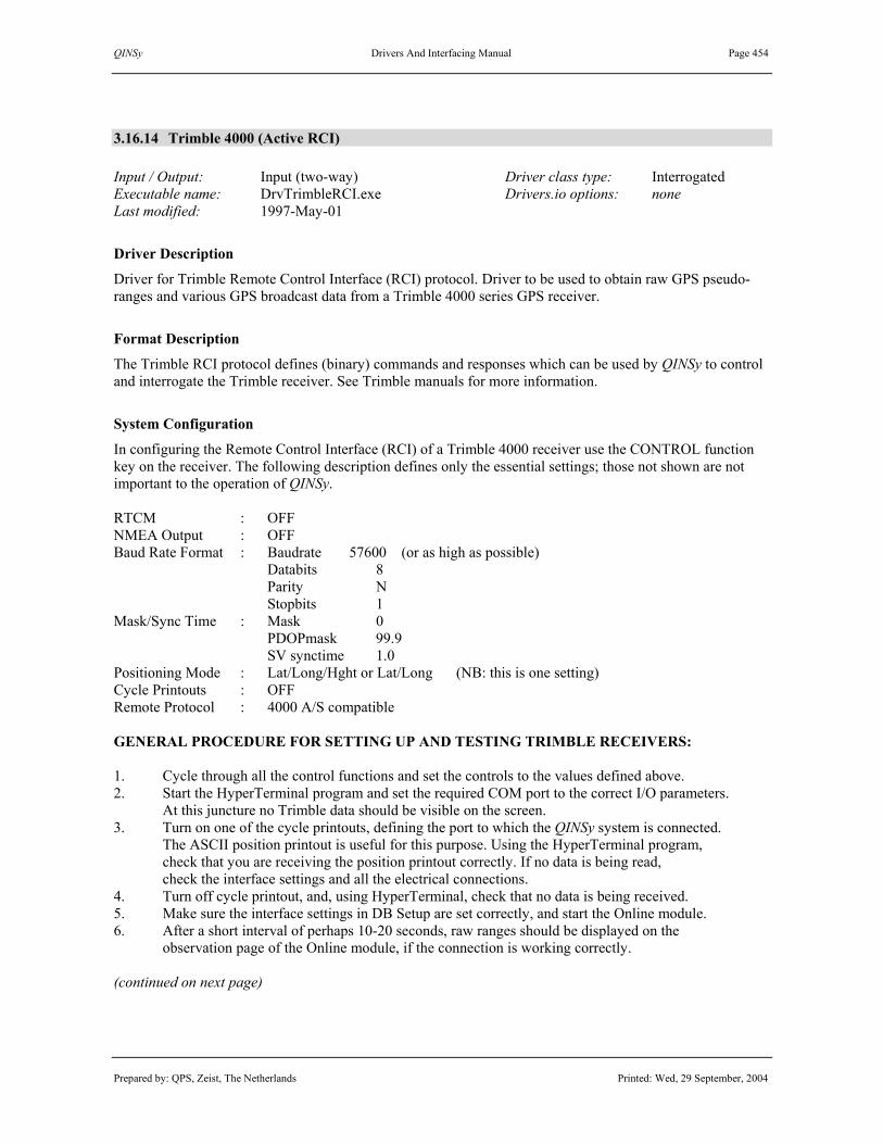
QINSy Drivers And Interfacing Manual Page 454
Prepared by: QPS, Zeist, The Netherlands Printed: Wed, 29 September, 2004
3.16.14 Trimble 4000 (Active RCI) Input / Output: Input (two-way) Driver class type: Interrogated Executable name: DrvTrimbleRCI.exe Drivers.io options: none Last modified: 1997-May-01
Driver Description
Driver for Trimble Remote Control Interface (RCI) protocol. Driver to be used to obtain raw GPS pseudo-ranges and various GPS broadcast data from a Trimble 4000 series GPS receiver.
Format Description
The Trimble RCI protocol defines (binary) commands and responses which can be used by QINSy to control and interrogate the Trimble receiver. See Trimble manuals for more information.
System Configuration
In configuring the Remote Control Interface (RCI) of a Trimble 4000 receiver use the CONTROL function key on the receiver. The following description defines only the essential settings; those not shown are not important to the operation of QINSy. RTCM : OFF NMEA Output : OFF Baud Rate Format : Baudrate 57600 (or as high as possible) Databits 8 Parity N Stopbits 1 Mask/Sync Time : Mask 0 PDOPmask 99.9 SV synctime 1.0 Positioning Mode : Lat/Long/Hght or Lat/Long (NB: this is one setting) Cycle Printouts : OFF Remote Protocol : 4000 A/S compatible GENERAL PROCEDURE FOR SETTING UP AND TESTING TRIMBLE RECEIVERS: 1. Cycle through all the control functions and set the controls to the values defined above. 2. Start the HyperTerminal program and set the required COM port to the correct I/O parameters.
At this juncture no Trimble data should be visible on the screen. 3. Turn on one of the cycle printouts, defining the port to which the QINSy system is connected.
The ASCII position printout is useful for this purpose. Using the HyperTerminal program, check that you are receiving the position printout correctly. If no data is being read, check the interface settings and all the electrical connections.
4. Turn off cycle printout, and, using HyperTerminal, check that no data is being received. 5. Make sure the interface settings in DB Setup are set correctly, and start the Online module. 6. After a short interval of perhaps 10-20 seconds, raw ranges should be displayed on the
observation page of the Online module, if the connection is working correctly. (continued on next page)

QINSy Drivers And Interfacing Manual Page 455
Prepared by: QPS, Zeist, The Netherlands Printed: Wed, 29 September, 2004
Interfacing Notes
This directive is applicable when interfacing the Trimble 4000 directly to the QINSy system, in the case where a Trimble OSM interface box is not supplied. If a longer cable is needed, just make a direct 2-2, 3-3 and 7-7 connection from the DB25 end to the multiple COM board (e.g. Digi 8e).
Database Setup
See description under “SATELLITE NAVIGATION SYSTEM DRIVERS”.

QINSy Drivers And Interfacing Manual Page 456
Prepared by: QPS, Zeist, The Netherlands Printed: Wed, 29 September, 2004
3.16.15 Trimble 7400 RealTime Survey Data
Input / Output: Input (two-way) Driver class type: Counted Executable name: DrvTrimbleRT.exe Drivers.io options: ACTIVE | PASSIVE Last modified: 1998-Oct-07
Driver Description
Driver for Trimble 7400 series Real Time Survey Data (RT17). Driver extracts pseudoranges, ephemerides, ionospheric and utc data and optionally position information from the receiver.
Format Description
For this driver the “Trim Comm” protocol is used. This format has evolved from the “Data Collector” format found with the Trimble 4000 series receivers. The Remote Protocol (Under <Control> must be set to “4000 A/S compatible”.
System Configuration
The Trimble 7400 receivers can be configured using the remote controller program (RemCon). • Receiver Port Config: Set the interface parameters for the receiver. − Click the “CONTROL” key − Click the “ALPHA” key to go down one screen − Click the <SERIAL PORT SETUP> key to configure the serial port I/O settings. Clicking the “ALPHA”
key changes the values. The next field can be reached by pressing the “ENTER” key. • Configure the receiver raw data output format by the following sequence on the simulated display − Click the “CONTROL” key − Click the “ALPHA” key to go down one screen − Click the <SERIAL PORTS OUTPUT> softkey − Click the <RT!&/BINARY OUTPUT> softkey − Now set the following using the “ALPHA” and “ENTER” key: − PORT: the port to which QINSy is connected, i.e. 1 to 4. − CONCISE: on − MEASUREMENTS: 1 HZ − R-T FLAGS: on − POSITIONS: off or 1 HZ − EPHEMERIS: on
Interfacing Notes
All four IO ports of the receiver can be used. The following table shows where the ports are located .
Port # Connector Port 1 PWR I/O 1 Port 2 I/O 2 Port 3 PWR 2&3 Port 4 AUX
(continued on next page)

QINSy Drivers And Interfacing Manual Page 457
Prepared by: QPS, Zeist, The Netherlands Printed: Wed, 29 September, 2004
Interfacing Notes (continued)
The wiring for the receiver has to be bi-directional. Either Trimble supplied cables can be used together with a DB-9 to DB-25 converter, or a special made cable. Pin numbers of the 5 and 7 pin LEMO plugs are shown below. The view is towards the rear panel of the receiver, which is the same as the soldering end of the plug.
The 7-pin LEMO ports 2 and 4 have to be wired as follows:
LEMO
7-pin I/O 2 or AUX
DB-9 COM DB-25 COM
Pin 1 SG ---------------- Pin 5 SG Pin 7 SG Pin 3 Data in ---------------- Pin 3 TXD Pin 2 TXD Pin 7 Data out ---------------- Pin 2 RXD Pin 3 RXD
The 5-pin LEMO port 1 and 3 have to be wired as follows:
LEMO
5-pin PWR 2&3 PWR-I/O 1
DB-9 COM DB-25 COM
Pin 3 Data in ---------------- Pin 3 TXD Pin 2 TXD Pin 4 SG ---------------- Pin 5 SG Pin 7 SG Pin 5 Data out ---------------- Pin 2 RXD Pin 3 RXD
Database Setup
See description under “SATELLITE NAVIGATION SYSTEM DRIVERS”. If the position output is also configured, select item “Systems” under the object and define a new “Position navigation system”. Select the same driver, I/O parameters and antenna node as with the satellite system. See description under “POSITION NAVIGATION SYSTEM DRIVERS”.

QINSy Drivers And Interfacing Manual Page 458
Prepared by: QPS, Zeist, The Netherlands Printed: Wed, 29 September, 2004
3.16.16 Trimble DSM (TSIP)
Input / Output: Input (two-way) Driver class type: Terminated <ETX> Executable name: DrvTrimbleSIP.exe Drivers.io options: none Last modified: 1997-Jun-10
Driver Description
Driver for Trimble DSM (DGPS Survey Module) GPS receiver, using the TSIP (Trimble Standard Interface Protocol) messages to obtain raw GPS pseudo-ranges and various GPS broadcast data from the receiver.
Format Description
The Trimble SIP protocol defines (binary, stuffed) commands and reports which can be used by an external computer to interrogate a Trimble DSM receiver. The protocol was originally defined for TANS (Trimble Advanced Navigator Sensor) and is also known as the ANS protocol. See Trimble manuals for more info.
Interfacing Notes
It is important that the wiring of the cables between the DSM and the PC COM port is bi-directional. Every time QINSy needs new ephemerides (e.g. at initialisation or with new satellites), it will ask the receiver for it. Port B (Control) is designed for RS-232 data connections and is reserved for TSIP input and output. Only Port B lets the QINSy System Configuration, control, and transfer raw GPS data using the TSIP interface. The wiring of the 9-pin control port B of the Trimble DSM receiver (using the DSM adapter cable to disable hardware flow control) to a 9-pin or 25-pin multiple COM interface board (e.g. Digi 8e) must be as follows:
DB-9 DSM DB-9 COM DB-25 COM Pin 2 TXD ---------------------- Pin 2 RXD Pin 3 RXD Pin 3 RXD ---------------------- Pin 3 TXD Pin 2 TXD Pin 5 SG ---------------------- Pin 5 SG Pin 7 SG
Database Setup
See description under “SATELLITE NAVIGATION SYSTEM DRIVERS”.

QINSy Drivers And Interfacing Manual Page 459
Prepared by: QPS, Zeist, The Netherlands Printed: Wed, 29 September, 2004
3.16.17 Trimble DSM (TSIP) PosNet
Input / Output: Input (two-way) Driver class type: Counted Executable name: DrvTrimbleSIPPOD.exe Drivers.io options: none Last modified: 1997-Jun-16
Driver Description
Driver for PosNet pod Trimble DSM GPS receiver, using the special TSIP Packet 6F Subcode 3 to obtain raw GPS pseudo-ranges from the receiver. This special Short Synchronised Measurement Packet was developed to meet WGC’s specifications and is encapsulated in a proprietary wrapper for use in a radio link. This driver cannot be used as the only GPS system in QINSy, since it will not decode satellite ephemerides and other GPS broadcast data. The PosNet pod does not output these data and cannot be queried to do so. Therefore, it is important that at least one other GPS receiver is available in the same QINSy setup.
Interfacing Notes
See description under “Trimble DSM (TSIP)” driver for interfacing information.
Database Setup
See description under “SATELLITE NAVIGATION SYSTEM DRIVERS”. When defining the PR observations, enter the appropriate mobile unit id’s as slot numbers: the sending unit number as slot 1 identifier and the receiving unit number as slot 2 identifier.
Additional Notes
The driver is able to decode more than one TSIP Packet 6F from the same PosNet pod radio link receiver, for example if more than one mobile unit is sending raw GPS pseudoranges. Just a “Satellite navigation system” with driver “Trimble DSM (TSIP) PosNet” for each of the mobile units. Be sure to select the same COM port number and interface parameters for each of these systems, and that slot identifiers correspond to the mobile unit combination which is to be decoded. Only the sending unit identifiers will be different, the receiving unit identifiers will be the same, but this number still has to be entered. QINSy will regard each of the systems as separate GPS systems, but only one driver process has to be started, and only one COM port has to be used.

QINSy Drivers And Interfacing Manual Page 460
Prepared by: QPS, Zeist, The Netherlands Printed: Wed, 29 September, 2004
(This page intentionally left blank)

QINSy Drivers And Interfacing Manual Page 461
Prepared by: QPS, Zeist, The Netherlands Printed: Wed, 29 September, 2004
3.17 DIFFERENTIAL CORRECTIONS SYSTEM DRIVERS
Database Setup
Select item “Auxiliary systems” and add a new “Differential corrections system” to the QINSy database. Select the appropriate driver and interface parameters. Press the “Next” button to define reference stations. Enter the transmitting station number(s) as slot number(s); because only those stations will be decoded from the differential corrections messages. Press the “Finish” button to save the system. See example below.

QINSy Drivers And Interfacing Manual Page 462
Prepared by: QPS, Zeist, The Netherlands Printed: Wed, 29 September, 2004
Database Setup (continued)
A new reference station can be added by pressing the “Add” button on the second page of the system wizard, or by selecting the system in the database setup tree and select option “New Reference Station”. To change station properties, expand the corrections system in the database setup tree, and select and edit the station.
See for more information the QINSy DB Setup Help Topics or the QINSy Knowledge Base.

QINSy Drivers And Interfacing Manual Page 463
Prepared by: QPS, Zeist, The Netherlands Printed: Wed, 29 September, 2004
3.17.1 Aquarius (Port A)
3.17.2 Aquarius (Port B) Input / Output: Input (two-way) Driver class type: Terminated <ETX> Executable name: DrvAquarius.exe Drivers.io options: A | B Last modified: 2003-Dec-10
Driver Description
See description under “SATELLITE NAVIGATION SYSTEM DRIVERS.

QINSy Drivers And Interfacing Manual Page 464
Prepared by: QPS, Zeist, The Netherlands Printed: Wed, 29 September, 2004
3.17.3 NMEA RTCM (DGPRC-DGDDC-DGREF) Input / Output: Input Driver class type: Terminated <LF> Executable name: DrvRTCMNMEA.exe Drivers.io options: format Last modified: 1997-May-1
Driver Description
Driver to decode RTCM SC-104 differential correction messages, “$DGPRC” (Pseudo Range Correction, RTCM types 1 & 9), “$DGDDC” (Delta-Differential Correction, RTCM type 2), and “$DGREF” (Reference station position, type 3), as output by for example a Trimble 4000 GPS receiver. This output is a decoded and scaled ASCII representation of the RTCM messages. The format is similar to NMEA-0183 messages.
Format Description
All three message types start with a “$” to mark the beginning of a new message, followed by “DG” to identify the message as Differential GPS data. The format of the RTCM messages are as follows. PRC - Pseudorange Correction (RTCM types 1 and 9) PRC,xxxx,xx,xxxx.x,xx,xxxx.xx,xxxx.xx,xxx,xx,[*hh]<CR><LF> DDC - Delta-Differential Correction (RTCM type 2) DDC,xxxx,xx,xxxx.x,xx,xxxx.xx,xxxx.xx,xxx,xx,[*hh]<CR><LF>
Field Format Description Values, Range, Units 1 xxxx reference station number 0 … 9999 2 xx reference station health 0 … 7 3 xxxx.x z-count time flag 0 … 3599.4 s 4 xx satellite number 1 … 32 5 xxxx.xx pseudo-range correction 6 xxxx.xx pseudo-range rate correction 7 xxx ephemeris issue number 0 … 255 8 xx User Differential Range Error 0, 1, 2, 3 9 *hh checksum EOR of values between “S” and “*”
REF - Reference Station Position (RTCM type 3) REF, xxxx,xx,xxxx.x,xxxxx.xxx,xxxxx.xxx,xxxxx.xxx,[*hh]<CR><LF>
Field Format Description Values, Range, Units 1 xxxx reference station number 0 … 9999 2 xx reference station health 0 … 7 3 xxxx.x z-count time flag 0 … 3599.4 s 4 xxxxx.xxx x-coordinate 5 xxxxx.xxx y-coordinate 6 xxxxx.xxx z-coordinate 7 *hh checksum EOR of values between “S” and “*”
Database Setup
See description under “DIFFERENTIAL CORRECTIONS SYSTEM DRIVERS”.

QINSy Drivers And Interfacing Manual Page 465
Prepared by: QPS, Zeist, The Netherlands Printed: Wed, 29 September, 2004
3.17.4 RTCM-104 6 of 8
3.17.5 RTCM-104 6 of 8 [Bit-Slipped]
3.17.6 RTCM-104 8 of 8 Input / Output: Input Driver class type: Counted Executable name: DrvRTCM.exe Drivers.io options: SIX | EIGHT Last modified: 1997-May-1
Driver Description
Driver to decode (binary) RTCM SC-104 VERSION 2 differential correction messages of types 1, 2, 3, 9 and/or 16, containing Differential GPS Corrections, Delta Differential GPS Corrections, Reference Station Parameters, High Rate Differential GPS Corrections and User Definable Special Message, respectively. The RTCM ‘(6-of-8)’ driver reads the RTCM-104 message in the standard 6 bits per byte format. The RTCM ‘(8-of-8)’ driver reads the RTCM-104 message in GeoTeam’s (non-standard) 8 bits per byte format.
Format Description
RTCM messages consist of 2 thirty-bit header words, containing reference station information, the reference time, and frame synchronisation information, followed by N words containing the data of the message. See the RTCM Recommended Standards for Differential NAVSTAR GPS Service (Version 2) for information.
Database Setup
See description under “DIFFERENTIAL CORRECTIONS SYSTEM DRIVERS”.

QINSy Drivers And Interfacing Manual Page 466
Prepared by: QPS, Zeist, The Netherlands Printed: Wed, 29 September, 2004
3.17.7 Sercel NR103 (Passive Corrections)
3.17.8 Sercel NR203 (Passive Corrections)
Input / Output: Input (two-way) Driver class type: Terminated <ETX> Executable name: DrvNR103.exe Drivers.io options: none Last modified: 1997-May-1
Description
See description under “SATELLITE NAVIGATION SYSTEM DRIVERS”.
3.17.9 Sercel NR203 (Active Corrections)
Input / Output: Input (two-way) Driver class type: Interrogated Executable name: DrvNR203.exe Drivers.io options: none Last modified: 1997-Aug-31
Description
See description under “SATELLITE NAVIGATION SYSTEM DRIVERS”.

QINSy Drivers And Interfacing Manual Page 467
Prepared by: QPS, Zeist, The Netherlands Printed: Wed, 29 September, 2004
3.18 OUTPUT SYSTEM DRIVERS
Database Setup
Select item “Auxiliary systems” and add an “Output system” to the QINSy Database . If an output system is added for an “Object”, then the system will still be defined as an “Auxiliary system”. Select the output driver and set the serial I/O parameters. The output rate will be the maximum update rate. It is adviced to set the output rate to at least 1 second. Press “Finish” button to save the output system setup. See example below.
Note. Output drivers without user interface need to be “triggered” the first time online by selecting the computation and node to output in the Controller menu “Settings – Node Output”. The selection will be stored in the QINSy database for the next time online. Output drivers with user interface will usually startup with an icon in the Windows task bar. Restore the driver window the first time online and enter the output node and other parameters. The selection(s) will be stored in the Windows registry settings for the current user. See for more information the QINSy DB Setup Help Topics or the QINSy Knowledge Base.

QINSy Drivers And Interfacing Manual Page 468
Prepared by: QPS, Zeist, The Netherlands Printed: Wed, 29 September, 2004
(this page intentionally left blank)

QINSy Drivers And Interfacing Manual Page 469
Prepared by: QPS, Zeist, The Netherlands Printed: Wed, 29 September, 2004
3.18.1 6041 Win Socket Output Input / Output: Output Driver class type: Output Executable name: DrvOut6041.exe Drivers.io options: none Last modified: 2001-Jul-16
Driver Description
This driver (with user interface) is used to send various raw sensor observations (incl. Sidescan images), node positions, object SOG, sound velocity profiles and geodesy set-up to the Reson 6041 software package. Either Survey Datum or Secondary datum must be set as WGS-84 because all output positions are referenced to the WGS-84 Datum. If no WGS-84 datum is set then positions will NOT be output. After controller is started, the 6041 Output Driver Dialog can be selected by clicking on it’s icon in the taskbar. In the dialog, one can view some status info and select the computation for the results that should be output. Dialog contents: 1) Click button “Select Computations...” in order to select an computation. This information is stored in the registry and will be reloaded next time the controller is started. 2) Status – Network Connection This displays the status of the actual connection to the 6041 computer. Connecting means that the driver is trying to establish a connection but has not yet succeeded. Sending means it has established connection and is now transferring data to 6041 computer. The connection status code is displayed between the brackets. 3) Status – Waiting Messages This gives an indication of how many messages are in a queue waiting to be sent. Normally the driver stores the incoming data in a queue for 5 seconds in order to send everything sorted in time to 6041. Size depends on how many sensors are sending data to QINSy. 4) Status- Current Timestamp Shows Timestamp that is used for time tagging messages to 6041.

QINSy Drivers And Interfacing Manual Page 470
Prepared by: QPS, Zeist, The Netherlands Printed: Wed, 29 September, 2004
Format Description
Formats are described in the Reson propriety 6041/6042 Interface Specification. An overview is given below of the possible sent messages. -Control Packets These packets send information about the current session and set-up. Except for the Command packet, they are all sent at start-up of the controller only.
• SyncTime Used to synchronize both computer times
• SysConfig Contains which systems and objects are used in the current set-up
• Command Used to synchronize recording process between the two software packages
• Geodesy Contains all set-up data regarding the selected spheroid, datum, datum transformation and Projection. This packet is used by 6041 to calculate grid coordinates.
• SVP Contains profile points from the currently selected sound velocity profile
-Raw Observation Packets These packets send various raw sensor observations from various system types. The driver will send for every applicable system that is encountered in the set-up, the packet as described below as soon as it detects that a new observation is available. A system selection dialog in order to reduce the number of packets being send over is not (yet) available.
• Bathymetry Contains complete swath from a MULTIBEAM ECHOSOUNDER SYSTEM
• Sidescan This contains all raw image data from a SIDESCAN SONAR SYSTEM
• Position Contains position obtained from a POSITION NAVIGATION SYSTEM
• Heading Contains compass heading observation obtained from a GYRO SYSTEM
• Attitude This package contains the Pitch and Roll values obtained from a PITCH, ROLL AND HEAVE SENSOR
• Heave Contains the Heave values as obtained from a PITCH, ROLL AND HEAVE SENSOR
• Altitude Contains the Altitude values obtained from a SURFACE NAVIGATION SYSTEM that outputs a ROV Altitude observation
• Depth This contains the ROV Depth observation obtained from a SURFACE NAVIGATION SYSTEM
• Tide Contains the Tide value from a TIDE GAUGE SYSTEM
-Result Packages
• SpeedOG Contains Speed over ground information of an objects’ reference node. The driver will send one SpeedOG message for every object it encounters in the current set-up, as soon as new computation result data becomes available. This is usually once a second.

QINSy Drivers And Interfacing Manual Page 471
Prepared by: QPS, Zeist, The Netherlands Printed: Wed, 29 September, 2004
• Position This packet uses the identical format as the Position package mentioned under Raw Observation Pack, but this packet contains the node position which is calculated by the computation. Driver outputs all the node results of nodes that are connected to either a USBL transponder or a SIDESCAN SONAR S SYSTEM. I will be send as soon as new node results become available, usually once a second.
Notes: -a built-in security prevents Multibeam data originating from non-Reson MBE Systems being send over. -sidescan Sonar packages originating from “old” Sidescan Systems can NOT be send over.
Database Set-up
Since this is a winsocket driver that uses an TCP/IP network connection, one must select a valid port number and IP number of the computer on which 6041 runs. For more information regarding setup see description under “OUTPUT SYSTEM DRIVERS”.
Controller Setup
Online, for this driver it is not necessary / possible to select a node in the controller under “Node Output…” menu.

QINSy Drivers And Interfacing Manual Page 472
Prepared by: QPS, Zeist, The Netherlands Printed: Wed, 29 September, 2004
3.18.2 ADCP Lat/Lon & X/Y Position (Node Output | Steered Point)
3.18.3 ADCP X/Y Position (Node Output | Steered Point) Input / Output: Output Driver class type: Output Executable name: DrvOutPosition.exe Drivers.io options: STEER Last modified: 2004-Aug-09 SYL | FQ | Q | ADCP | SNGLL | T | G
Driver Description
Driver to output an ASCII string containing date, time, lat/lon/height, easting/northing/heigth, speed and course to an ADCP System. Positions are skewed for the time of output. Two types of output modes: 1. position for currently selected output position, as set in Controller’s Node Output; 2. Steered Point position for currently active steered node, determined by the Controller (Online).
Format Description
ADCP Lat/Lon & X/Y The ASCII string starts with a header (see Drivers.io Options) and is terminated by a Carriage Return and a Line Feed. Fields are separated by commas and of fixed length (except when the value is too large to fit). $GHR,DDMMYY,HHMMSS,DDMM.MMMMMMH,DDDMM.MMMMMMH,HHH.HH,EEEEEE.EE,NNNNNN.NN,HHH.HH,SS.SS,CCC.CC<CRLF>
Field Format Description Values, Units
1 $AAA header “$” + Driver.io string 2 DDMMYY UTC date of positions day month year 3 HHMMSS UTC time of positions hours minutes seconds 4 DDMM.MMMMMMH latitude on survey datum degrees minutes hemisphere 5 DDDMM.MMMMMMH longitude on survey datum degrees minutes hemisphere 6 HHH.HH height above survey datum survey units 7 EEEEEE.EE easting on projection grid survey units 8 NNNNNN.NN northing on projection grid survey units 9 HHH.HH height above projection grid survey units 10 SS.SS speed over ground survey units / second 11 CCC.CC course over ground degrees 11 <CRLF> record termination <CR><LF>
ADCP X/Y This ASCII string does not start with a header. It is terminated by a Carriage Return and a Line Feed. Fields are of fixed length (except when the value is too large to fit). Normally, its length will be 46 bytes. HH:MM:SS EEEEEEEE.EE NNNNNNNN.NN HHH.HH<CRLF>
Field Format Description Values, Units 1 HH:MM:SS UTC time of positions hours : minutes :seconds 2 EEEEEEEE.EE easting on projection grid survey units 3 NNNNNNNN.NN northing on projection grid survey units 4 HHH.HH heading of vessel object degrees 5 <CRLF> record termination <CR><LF>

QINSy Drivers And Interfacing Manual Page 473
Prepared by: QPS, Zeist, The Netherlands Printed: Wed, 29 September, 2004
Encoding Notes
When PPS is used by QINSy, time will be UTC, otherwise it will be the QINSy computer’s systemtime. The header is obtained from the Drivers.io file. When the header is not empty, a “$” character is added to the start of the output string, so that it resembles a NMEA output string. Presently, the header is “$GHR”. Heading or course over ground reference is obtained from the Drivers.io command line. See below.
Drivers.io Options
Command line parameters are evaluated in the next sequence. “STEER” will use the Steered Node position, otherwise the position is used for the node that is selected in the Controller’s Node Output settings. “G” will output headings and CMG values with respect to grid north. “T” will output heading and CMG with respect to true north. Otherwise, headings will be true bearings and CMG values will be grid bearings. “SYL” will start DrvOutPosition in Syledis mode. See “Syledis Y/X Position” driver description below. “SNGLL” will start DrvOutPosition in SNGLL mode. See “ADCP Lat/Lon Position ($SNGLL)” driver. “ADCP” will start DrvOutPosition with the ADCP X/Y format as described above. Any other command line string, such as “GHR”, or no string at all (except for “STEER”, “G” or “T”) will start DrvOutPosition with the ADCP Lat/Lon & X/Y format as described above. The actual command line string will be used as header. If the header is not empty, it will preceded by a “$” character, to resemble a NMEA string.
Database Setup
See description under “OUTPUT SYSTEM DRIVERS”.
Controller Setup
Online, except when the “Steered Point” option of this driver has been selected, the appropriate output node must be selected before the driver starts cycling. After going online with the Controller for the first time, select the “Node Output...” option under Settings and select an computation and node for this system. In case of outputting the Steered Node position, the user has to set up also one or more Steered Points.

QINSy Drivers And Interfacing Manual Page 474
Prepared by: QPS, Zeist, The Netherlands Printed: Wed, 29 September, 2004
3.18.4 ADCP Lat/Lon Position ($SNGLL) (Node Output | Steered) Input / Output: Output Driver class type: Output Executable name: DrvOutPosition.exe Drivers.io options: STEER Last modified: 2004-Aug-09 SYL | FQ | Q | ADCP | SNGLL | T | G
Driver Description
Driver will output an ASCII string, containing Date/Time, Position (Lat/Lon on Survey Datum), Speed and heading to Transect Remote Cherry Console of the RDI ADCP Doppler. The Position is skewed for the time of output. Two types of output modes: 1. Node Output position for currently selected output position, as set in Controller’s Node Output; 2. Steered Point position for currently active steered node, determined by the Controller (Online).
Format Description $SNGLL,ddmmyy,hhmmssss,DDMM.MMMMS,DDDMM.MMMMS,000000000.0,0000000.0,00,00000.0000E,0,0,vv.vv,hhh.h<CR><LF> All fields are comma separated. Some fields are not used, and therefore filled with zero’s. ddmmyy Date (day, month, year) hhmmssss Time (Hours, minutes, seconds, milliseconds always zero) DDMM.MMMM Latitude in decimal degrees S Sign of Latitude ‘N’ or ‘S’ DDDMM.MMMM Longitude in decimal degrees S Sign of Latitude ‘W’ or ‘E’ vv.vv Speed in m/s hhh.h Heading in degrees <CR><LF> Carriage return + Linefeed
Format Example $SNGLL,190600,15053200,2815.0395N,04936.0700E,000000000.0,0000000.0,00,00000.0000E,0,0,01.6,026.0, $SNGLL,190600,15053400,2815.0405N,04936.0706E,000000000.0,0000000.0,00,00000.0000E,0,0,01.6,026.0, $SNGLL,190600,15053500,2815.0414N,04936.0711E,000000000.0,0000000.0,00,00000.0000E,0,0,01.7,026.0,
Encoding Notes
If the computation fails for the current steered point, its position will be predicted for the number of seconds set in the Filter option in the Controller (default 10 seconds) and then changed automatically to the next steered point. If there is no more steered point left, the last known position will be outputted.
Database Setup
See description under “OUTPUT SYSTEM DRIVERS”.
Controller Setup
Online, except when the “Steered Point” option of this driver has been selected, the appropriate output node must be selected before the driver starts cycling. After going online with the Controller for the first time, select the “Node Output...” option under Settings and select an computation and node for this system. In case of outputting the Steered Node position, the user has to set up also one or more Steered Points.

QINSy Drivers And Interfacing Manual Page 475
Prepared by: QPS, Zeist, The Netherlands Printed: Wed, 29 September, 2004
3.18.5 Anchor Output (Network) Input / Output: Output Driver class type: UDP/IP Output Executable name: DrvOutAnchors.exe Drivers.io options: None Last modified: 2004-Jul-13
Driver Description
Driver to be used to send the anchor configuration/position of the QINSy computer on which this driver is installed to another QINSy computer. The latter can visualize the anchors from the other machine. Driver is used in conjunction with Anchor input Driver. Both computers should be connected together through their network connection; this can either be a direct cross over cable or though a hub. The TCP/IP settings on both machines should be set-up correctly. Note: The anchor positions are transferred as Eastings/Northings on the survey datum so for correct visualization it is important that both QINSy’s have the same geodetic set-up. The driver sends status information and position of all the anchors on every update.
Format Description
Each output message is variable in length, depending on the number of anchors. It contains a header and for every anchor an sAnchorDef Structure and an sAnchorPosition structure and finally a footer. Header Item Format Description Values 01 STX STX Always 02 02 ID Message Id 0 03 Size Overall Message Size incl. Header Typically 1070 bytes for 2 anchors 04 Sender ID String of max 100 bytes “QINSy Output Driver” 05 Anchor Count Number of Anchors In Message Usually up to 12 anchors
Anchor Definition Array This block contains AnchorCount times an sAnchorDef structure. Structure layout is proprietary information. Anchor Position Array This block contains AnchorCount times an sAnchorPos structure. Structure layout is proprietary information. Footer Item Format Description Values 01 Checksum From STX up to field before this field NOT USED YET 02 ETX ETX Always 03
Database Setup
See description under “OUTPUT SYSTEM DRIVERS”. Update time can be set to 1 second, this is sufficient.

QINSy Drivers And Interfacing Manual Page 476
Prepared by: QPS, Zeist, The Netherlands Printed: Wed, 29 September, 2004
3.18.6 Atlas Deso 15 Annotator (Node Output | Steered Point) Input / Output: Output Driver class type: Output Executable name: DrvOutFish.exe Drivers.io options: DES | STEERED Last modified: 2000-Jun-13
Driver Description
Driver to be used to generate output strings compatible with the Atlas Deso 15 annotator. This system annotates the Atlas Deso 15 echosounder. The output driver has a hard coded output format. Output will only be generated on fix updates. Two output position modes are: 1. position for currently selected output node, as set in the Controller’s Node Output; 2. Steered Point position for currently active steered point, determined by the Controller (Online).
Format Description
Each output sentence is variable in length, depending on the values that are encoded. WFix# dd/mm/yy hh:mm:ss E: 875855.16 N: 5985508.61<CR><LF> Item Format Description Values 01 W Start of text 02 Fix# Fix number 1 03 dd/mm/yy Date 01/05/2000 04 hh:mm:ss time 23:59:59 05 E: 875855.16 Easting in meters 875855.16 06 N: 5985508.61 Northing in meters 5985508.61
Format Example W1 01/05/2000 23:59:59 E: 875855.16 N: 5985508.61
Database Setup
See description under “OUTPUT SYSTEM DRIVERS”.
Controller Setup
Online, except when the “Steered Point” option of this driver has been selected, the appropriate output node must be selected before the driver starts cycling. After going online with the Controller for the first time, select the “Node Output...” option under Settings and select an computation and node for this system. In case of outputting the Steered Node position, the user has to set up also one or more Steered Points.

QINSy Drivers And Interfacing Manual Page 477
Prepared by: QPS, Zeist, The Netherlands Printed: Wed, 29 September, 2004
3.18.7 Atlas Fansweep 20 Output Driver Input / Output: Output Driver class type: Output Executable name: DrvOutFanSweep.exe Drivers.io options: WGS84 Last modified: 1999-Feb-03
Driver Description
Driver for outputting an ASCII string to the Atlas Fansweep 20 System, output every QINSy update on whole second. The update-rate can be defined as system property in DB Setup. The string contains NMEA GGA, ZDA and VTG records with data of the selected node. In the GGA/GLL string the time is that for the position, whilst the time in the ZDA string is that at which the data was put on the output port.
Format Description
Refer to the NMEA drivers for a full description of the GPGGA, GPGGL, GPZDA, GPVTG messages.
Format Example $GPGGA,092155.00,521123.49,N,0051657.88,E,2,00,0.0,77.0,M,,M,,*40 $GPGLL,521123.49,N,0051657.88,E,092155.00,A*05 $GPVTG,165.1,T,,M,0.35,N,0.65,K*66 $GPZDA,092156.40,02,03,1999,,*62
Database Setup
See description under “OUTPUT SYSTEM DRIVERS”. The "Atlas Fansweep 20 (WGS84)" version, will present the position as is being output in the GPGGA part, in the WGS84 datum. The "Atlas Fansweep 20" version will give the positions relative to the survey datum. Note that the correct datum shift parameters must have been entered in the Geodetic part of the DB Setup. The output rate will be the maximum update rate. It is adviced to set the output rate to at least 1 second.
Controller Setup
Online, except when the “Steered Point” option of this driver has been selected, the appropriate output node must be selected before the driver starts cycling. After going online with the Controller for the first time, select the “Node Output...” option under Settings and select an computation and node for this system. In case of outputting the Steered Node position, the user has to set up also one or more Steered Points.

QINSy Drivers And Interfacing Manual Page 478
Prepared by: QPS, Zeist, The Netherlands Printed: Wed, 29 September, 2004
3.18.8 AutoPilot Euro500 Output Driver Input / Output: Output Driver class type: Output Executable name: DrvOutRobTrack.exe Drivers.io options: EURO500 Last modified: 1999-Sep-10
Driver Description
Driver (with user interface) for outputting settings to a Euro500 AutoPilot System, output every update. This update-rate can be defined as system property in DB Setup. The outputted offset will be calculated, using the selected AutoPilot Steered Node and the current Controller’s Mainline. The user has the possibility to define a Track Offset, which will be subtracted from the calculated offset. This might be useful when you want to sail e.g.10m starboard off the current mainline. In that case, define a Track Offset of +10m.
Format Description $1AO+xxxxx.xx<CRLF> • $1AO is always the same. (Note that O is not the zero character) • + means starboard of the line, - means port of the line. • xxxxx.xx means a multiple of 200mV, where 1m equals 200mV • <CRLF> means the Carriage Return and Linefeed character
Format Example
$1AO+00020.00 means offset of +0.1m $1AO+01000.00 means offset of +5.0m $1AO-02000.00 means offset of -10.0m
Encoding Notes
• The outputted offtrack will be the calculated offtrack of the selected node from the Controller’s Mainline MINUS the user-defined Track Offset (default zero).
• The outputted offtrack is rounded to the nearest 0.1m • Maximum offset should be less than 499.95m (which equals 99990.00 mV)
Database Setup
See description under “OUTPUT SYSTEM DRIVERS”. Note. For the best result it is advisable to define an AutoPilot Steering Node some meters ahead of the vessel (e.g. half the vessel length).

QINSy Drivers And Interfacing Manual Page 479
Prepared by: QPS, Zeist, The Netherlands Printed: Wed, 29 September, 2004
3.18.9 AutoPilot RobTrack/STS500 Output Driver Input / Output: Output Driver class type: Output Executable name: DrvOutRobTrack.exe Drivers.io options: none Last modified: 1999-Sep-01
Driver Description
Driver (with user interface) for outputting settings to a RobTrack AutoPilot System, output every QINSy update. This update-rate can be defined as system property in DB Setup. The outputted offset will be calculated, using the selected AutoPilot Steered Node and the current Controller’s Mainline.
Format Description $DNRTR,r.r,x.x,v.v,a.a,o.o,t.t*hh<CRLF> r.r : Track ref. (direction of track) Line Heading x.x : Cross track error (distance across) Positive when heading must change to port to get closer to track E.g. +12.2 -> Vessel must steer 12.2 to port Unit: metres v.v : Velocity along track. Positive when vessel SMG is in the track direction.
Unit: metres / second a.a : Velocity across. Positive when vessel moves to starboard. E.g. -0.33 -> vessel moves to port with 0.33 m/sec Unit: metres / second o.o: Track offset. Positive when vessel shall follow a parallel track to starboard side of track. E.g. +77 -> vessel moves to a parallel track 77m to starboard. Unit: metres t.t: Nav computer control of maximum allowed turn-rate. E.g. 20.0 means that the vessel will use 20 seconds to change the heading with one degree. Unit: seconds / degree hh: Checksum <CRLF> Carriage Return and Linefeed character
Database Setup
See description under “OUTPUT SYSTEM DRIVERS”. Note. For the best result it is advisable to define an AutoPilot Steering Node some meters ahead of the vessel (e.g. half the vessel length).

QINSy Drivers And Interfacing Manual Page 480
Prepared by: QPS, Zeist, The Netherlands Printed: Wed, 29 September, 2004
3.18.10 AUXCOM 3 (Position; Age=0) (Survey | WGS84)
3.18.11 AUXCOM 3 (Position and Age) (Survey | WGS84)
3.18.12 AUXCOM 3 (Skewed Position) (Survey | WGS84) Input / Output: Output Driver class type: Output Executable name: DrvOutAuxcom3.exe Drivers.io options: various Last modified: 1997-Sep-08
Driver Description
Driver for DNAVN ASCII Position Archive Data Stream (AUXCOM3) output strings. Driver to be used to generate output strings containing position and solution results from the QINSy system. The AUXCOM 3 output driver has two different types of output modes, time and datum: 1. Position; Age=0 position at time of fix with time of fix; age is not computed (0 seconds) 2. Position and Age position at time of fix with time of fix; age is update time − time of fix 3. Skewed Position position at update time with update time; age is 0 seconds by definition A. Survey position (latitude, longitude, height) on survey datum B. WGS84 position (latitude, longitude, height) on WGS84 datum
Format Description
Each AUXCOM3 record is variable in length, depending on the number of satellites tracked. The maximum record size, however, is limited by 15 SV's and is 211 bytes, computed as follows: header/position = 86 bytes, plus 15 SV's of 8 bytes per SV = 120 bytes, plus trailer = 5 bytes. The fields within the output record are of fixed length. Some fields are output as a single, hexadecimal digit (0-9, A-F). Each bit in such a field is a binary flag, organised from the most significant bit (MSB) to the least significant bit (LSB). Hex flag fields are represented by "x". Other fields are "n" (for decimal digit or part of decimal number), "mmddyy" (month, day, year), "hhmmss (hours, minutes, seconds), and "ddmmss" (degrees, minutes, seconds). Characters that do not change are indicated by quotes: ‘ ‘. [1365123197235959.901.11N521122.81E0051657.15+0058.0001.1002.2 3 2 3.3 2.2579990011A 01050050020500500305005004050050050500500605005007050050080500500905005010050050]
Byte Format Description Values, Range, Units 01 ‘[‘ start character ASCII 91 02 n day of week 0..6, 0 = Sunday 03 nnn day of year 1..366 06 mmddyy date month, day, year 12 hhmmss.s UTC (time of record) hours, minutes, seconds 20 ss.s time of record minus time of fix seconds 24 n datum flag 1 = WGS84 25 ‘N’ or ‘S’ latitude northern or southern 26 ddmmss.ss latitude degrees; minutes; seconds 35 ‘E’ or ‘W’ longitude eastern or western 36 dddmmss.ss longitude degrees; minutes; seconds 45 ‘+’ or ‘−’ height above or below ellipsoid 47 nnnn.n height meters wrt ellipsoid 53 nnn.n course over ground degrees true

QINSy Drivers And Interfacing Manual Page 481
Prepared by: QPS, Zeist, The Netherlands Printed: Wed, 29 September, 2004
58 nnn.n speed over ground knots 63 nnn 3D position error 1 sigma meters 66 nnn 2D position error 1 sigma meters 69 nn.n PDOP or F-test 73 nn.n HDOP 77 n operating mode 0 = no solution, 1 = 4 SV, 2 = 3 SV
+ alt aid, 3 = 3 SV + clk aid, 4 = 2 SV + alt/clk aid, 5 = all SV in view
78 n receiver mode 7 = C/A, L1 only, carrier aided 79 n receiver dynamics 0 = static, 1 = low, …, 9 = high 80 n position quality 0 = bad, …, 9 = good 81 n differential quality 0 = no corr., 1 = bad, …, 9 = good 82 mmss time since last correction minutes, seconds
maximum age is 60 seconds 86 x number of SV tracked maximum number = 'F' = 15 … +1 nn PRN number +3 nn SNR Trimble units +5 nnn range residual meters +8 x status flag BIT 0 is elevation (0 = above mask),
BIT 1 is SV health (0 = SV healthy) … N ']' stop character ASCII 93; N = 87 + number SV × 8 +1 xx checksum exclusive or from '[' to ']' inclusive +1 <CR><LF> record termination
Encoding Notes
QINSy sets predefined values for following fields (with column): receiver code ≡ 0 (78), receiver dynamics ≡ 9 (79), time since last correction ≡ 0 (82), satellite SRN values ≡ 0. The checksum is always computed.
Interfacing Notes
No specific interfacing or configuring recommendations. See Chapter 1 for general interfacing remarks.
Database Setup
See description under “OUTPUT SYSTEM DRIVERS”.
Controller Setup
Online, except when the “Steered Point” option of this driver has been selected, the appropriate output node must be selected before the driver starts cycling. After going online with the Controller for the first time, select the “Node Output...” option under Settings and select an computation and node for this system. In case of outputting the Steered Node position, the user has to set up also one or more Steered Points.

QINSy Drivers And Interfacing Manual Page 482
Prepared by: QPS, Zeist, The Netherlands Printed: Wed, 29 September, 2004
3.18.13 Bennex Left Right Indicator Input / Output: Output Driver class type: Output Executable name: DrvoutBennexLR.exe Drivers.io options: none Last modified: 2001-Feb-02
Driver Description
This driver sends the steered node line information (i.e. distance along line and distance off line) to the Bennex Left right indicator.
Format Description
ASCII output string, 39 bytes long, terminated by carriage return linefeed. The next string will server as an example for the description of the fields. S +53 –1001 180 306 000 003950 0000 0000 0000<CR><LF> Note: spaces are inserted for clarity.
Field Format Description Values, Range, Units S 1 char Mode G: storing, S: offline, N: No navigation
+53 sign + 2 digits Angle to the line degrees -1001 sign + 4 digits Distance offline decimeters 180 3 digits Line heading degrees 306 3 digits Course made good degrees 000 3 digits Speed over ground decimeters / second
003950 6 chars Line name 0000 4 digits MP (line) or KP (route) meters or kilometers 0000 4 digits Distance from start of line meters 0000 4 digits Depth centimeters
<CR><LF> 2 char End of message 0x0D, 0x0A
Format Example S+53-1501180306000004000000000000000 S+53-1500180306000003950000000000000 S+53-1001180306000003950000000000000
Decoding Notes
The mode is always set to offline, the depth field is always 0.0.
Database Setup
See description under “OUTPUT SYSTEM DRIVERS”.
Controller Setup
Because the driver outputs the Steered Node position, the user has to set up also one or more Steered Points.

QINSy Drivers And Interfacing Manual Page 483
Prepared by: QPS, Zeist, The Netherlands Printed: Wed, 29 September, 2004
3.18.14 Coda Navigation Output Driver Input / Output: Output Driver class type: Output Executable name: DrvOutSubspection.exe Drivers.io options: CODA | CDAT Last modified: 2000-Jun-02
Driver Description
Driver (with user interface) for outputting an ASCII string to a Coda Navigation System, output every QINSy update. The update-rate can be defined as system property in DB Setup. The string contains a Time and Kp-value (in meters) for the selected node. Notice that the Kp value is skewed for time of output.
Format Description
ASCII String, terminated by a carriage return linefeed.
Coda Format Example
CODA 123.354 33998.005 12.234 77.09 34.5 10.2 4.3 031.8 L_001 344 1453.89 1.03 797619096.002<CR><LF>
Coda-Date Format Example
CODA-DATE 123.354 33998.005 12.234 77.09 34.5 10.2 4.3 031.8 L_001 344 1453.89 1.03 15:50:00 20:04:94 <CR><LF> Item Format Description Example Values 01 "CODA" or
"CODA-DATE" Start character for Coda format or Start character for Coda-Date format
-
02 " " Space (ASCII #32) - 03 %.3lf Easting is UTM value of the tow fish in meters 123.354 04 %.3lf Northing is UTM value of the tow fish in meters 33998.005 05 %.3lf Kp is along-track kilometer point in kilometers 12.234 06 %.2lf Distance offtrack in meters 77.09 07 %.1lf Water depth of the tow fish in meters 34.5 08 %.1lf Altitude of the tow fish in meters 10.2 09 %.1lf Speed of the tow fish in knots 4.3 10 %5.1lf Heading of the tow fish in degrees (0 –360) 031.8 11 %s Survey line name (5 character ASCII string) L_001 12 %d Fix number 344 13 %.2lf Sound velocity in meters per second 1453.89 14 %.2lf Delay between the time of data receipt and the time of
transmission in seconds 1.03
15 %.3lf or hh:mm:ss dd:mm:yy
System UTC time since January 1st 1970 in seconds or in hour:minute:seconds day:month:year format
797619096.002 or 15:50:00 20:04:94
Database Setup
See description under “OUTPUT SYSTEM DRIVERS”.

QINSy Drivers And Interfacing Manual Page 484
Prepared by: QPS, Zeist, The Netherlands Printed: Wed, 29 September, 2004
3.18.15 CorrOcean Cathodic Protection System Output Driver
3.18.16 CorrOcean CP (Steered Point) Output Driver
Input / Output: Output Driver class type: Output Executable name: DrvOutCorrOcean.exe Drivers.io options: STEERED Last modified: 1999-Jan-12
Driver Description
Driver (with user interface) for outputting an ASCII string to a CorrOcean Cathodic Protection System, output every QINSy update. The update-rate can be defined as system property in DB Setup. The string contains a Time and Kp-value (in meters) for the selected node. In case the second driver has been selected, the output node used for the Kp calculation will always be the Steered Node. Notice that the Kp value is skewed for time of output.
Format Description
ASCII String, terminated by a carriage return, fixed length of 17 characters, inclusive the <CR>. HH:MM:SS sFFFFFF<CR> "HH:MM:SS" Hours, Minutes and Seconds.
It will be UTC time in case Pps is connected, otherwise computer system time. " " Space (ASCII #32) "s" Sign of the Kp value; ' ' when positive, '-' when negative. "FFFFFF" Kp value in meters, skewed for time of output. Always right-aligned in the string and proceeded with zero's. When the value exceed 999.999 Km, it will output 999999 in the string. "<CR>" Carriage Return (ASCII #13)
(Notice that there is no linefeed character)
Format Example
05:14:01 –001053 means Kp value of -1.053 05:14:02 -001052 05:14:03 -001050
Database Setup
See description under “OUTPUT SYSTEM DRIVERS”.
Controller Setup
Online, except when the “Steered Point” option of this driver has been selected, the appropriate output node must be selected before the driver starts cycling. After going online with the Controller for the first time, select the “Node Output...” option under Settings and select an computation and node for this system. In case of outputting the Steered Node position, the user has to set up also one or more Steered Points.

QINSy Drivers And Interfacing Manual Page 485
Prepared by: QPS, Zeist, The Netherlands Printed: Wed, 29 September, 2004
3.18.17 Echosounder Depth Output Input / Output: Output (User Interface) Driver class type: Output Executable name: DrvOutDepthUI.exe Drivers.io options: age Last modified: 2004-March-02
Driver Description
Driver with user interface, to be used to generate output strings containing raw (or corrected) depth values from Singlebeam, Multibeam or Multi-Transducer Echosounders, or DTM Results as calculated using depth values from one of these types of echosounders. Driver starts up as minimized window on Windows taskbar. Depending on the selected depth observation, several selections for beams and corrections are available: Singlebeam Echosounder Single Beam, DTM Results Multibeam Echosounder Nadir Beam, Center Beam, Min Depth, Max Depth, DTM Results Multi-Transducer Echosounder Center Beam, Minimum Depth, Maximum Depth, DTM Results Single Beam Raw Data Value, Corrected Data Value Nadir Beam Correct for Roll, Correct for Roll and Pitch Center Beam Raw Data Value, Correct for Roll, Correct for Roll and Pitch Minimum Depth Raw Data Value, Exclude Zero Values Maximum Depth Raw Data Value, Exclude Zero Values DTM Results Closest DTM Point, Interpolated Point If the “DTM Results” option is selected, the driver does not read the raw data value buffers, but the DTM results as calculated by the Multibeamer process. These data are always corrected for roll, pitch, heave and system offsets such as mounting angles and sound velocities. However, the echosounder system must have been selected on the Echosounder Parameters page of the Controller’s Session Setup Wizard. For the other options, the driver uses the roll and pitch values from the vertical reference unit that has been selected for the object on which the echosounder is defined. The (C-O) values for the roll and pitch values as well as the mounting offsets for a Multibeam or Multi-Transducer system are taken into account. The “Corrected Data Value” for a Singlebeam Echosounder is the raw data value, scaled by the “Calibrated Velocity” divided by the “Used Velocity” as defined with the system setup in the database. The “Corrected Data Value” that is available with a ROV depth or altitude observation, is the raw values, corrected for the (C-O) values and scale factor, that has been defined during the observation’s setup in the database. The Nadir Beam is always corrected for roll (including transducer roll offset). It is defined as the beam that is closest to the vertical direction after applying any roll compensation. Pitch compensation is optional. In order to find Minimum Depth or Maximum Depth, roll and pitch are always taken into account.
Format Description
Several output formats are available. Output strings are always ended by a <CR><LF> pair. (continued on next page)

QINSy Drivers And Interfacing Manual Page 486
Prepared by: QPS, Zeist, The Netherlands Printed: Wed, 29 September, 2004
NMEA $SDDPT $SDDPT,10.000,5.000,<CR><LF> Item Field Description Format, Units 01 $SDDPT Header “$SDDPT” 02 x.xxx Water Depth Value meters 03 x.xxx Transducer Offset to Reference Point meters 04 x.x Maximum Range Scale (empty) 05 <CR><LF> Termination Characters Carriage Return + Line Feed
NMEA $SDDBT $SDDBT,32.808,f,10.000,M,5.468,F<CR><LF> Item Field Description Units 01 $SDDBT Header “$SDDBT” 02 x.xxx, f Water Depth Value “f” = feet 03 x.xxx, M Water Depth Value “M” = meters 04 x.xxx, F Water Depth Value “F” = fathoms 05 <CR><LF> Termination Characters Carriage Return + Line Feed
ASCII Meters (x) 10 ASCII Units (x) 10 Item Field Description Format, Units 01 x Water Depth Value meters or survey units, 0 decimals 02 <CR><LF> Termination Characters Carriage Return + Line Feed
ASCII Meters (x.xxx) 10.000 ASCII Units (x.xxx) 10.000 Item Field Description Format, Units 01 x.xxx Water Depth Value meters or survey units, 3 decimals 02 <CR><LF> Termination Characters Carriage Return + Line Feed
Sonardyne NMEA $SONDEP $SONDEP,24.6,,M*58<CR><LF> Item Field Description Format, Units 01 $SONDEP Header “$SONDEP” 02 x.x Water Depth Value meters 03 x.xxx Observation error – field is blank if not sent 04 M Units: M = Meters, F = Feet Always M 05 *hh Checksum – not compulsory 06 <CR><LF> Termination Characters Carriage Return + Line Feed
NMEA $DBS $DBS,24.6,M*22<CR><LF> Item Field Description Format, Units 01 $SONDEP Header “$SONDEP” 02 x.x Water Depth Value meters 03 M Units: M = Meters Always M 04 *hh Checksum – not compulsory 05 <CR><LF> Termination Characters Carriage Return + Line Feed

QINSy Drivers And Interfacing Manual Page 487
Prepared by: QPS, Zeist, The Netherlands Printed: Wed, 29 September, 2004
Drivers.io Options
If the command line in the drivers.io file contains a value, then this value is used as maximum age for the output data, i.e. when the depth is more than this number of seconds old, the driver stops outputting data. Default value for the age (command line value) is 5.0 seconds. Delete the number to skip the age check.
Database Setup
See description under “OUTPUT SYSTEM DRIVERS”.
Controller Setup
Online, click on the Depth Output Driver button in the taskbar. Select Echosounder, Beam, Option, Format. The output data string is also shown. If there is no data update, or the data are invalid or too old, then no data string is sent and the edit box becomes empty. Selections are saved in the registry between sessions.

QINSy Drivers And Interfacing Manual Page 488
Prepared by: QPS, Zeist, The Netherlands Printed: Wed, 29 September, 2004
3.18.18 Fish output to 6041 (WinSocket) Input / Output: Output Driver class type: Output Executable name: DrvOutFish6041.exe Drivers.io options: none Last modified: 2000-Oct-5
Driver Description
Driver to be used to generate an output string compatible with the Reson 6041 software. The output driver has a hard coded output format and will only output data that originates from the following drivers: 1. Klein2000 SSS VRU R-P (with Annotation) located in the “Pitch, roll and heave sensor” systems. 2. Klein2000 SSS Heading (with Annotation) located in the “Gyro's and compasses” systems. 3. Klein2000 SSS Info (with Annotation) located in the “Surface navigation system” category. 4. Klein2000 SSS Info (with Annotation) located in the “Miscellaneous systems” category. 5. Klein595 SSS Altitude (with Annotation) located in the “Surface navigation system” category When no VRU or Heading system is available the roll & pitch or heading information from the object on which the selected node is located will be used in the output message
Format Description
Item Format Description Remarks 01 WORD Identifier Always 0x4845 02 WORD Packet type Always 0x01 03 Float Temperature from fish Degrees Celsius 04 Float Fish altitude Meters 05 Float Fish depth Meters 06 Float Fish heading Degrees 07 Float Fish pitch Degrees 08 Float Fish roll Degrees 09 Float SSS range setting Meters 10 Float Fish speed Knots 11 Double Fish easting Survey units 12 Double Fish northing Survey units 13 Double Time stamp of position Seconds since Jan 1st, 1970 14 Double Time stamp of fish information Seconds since Jan 1st, 1970
Database Setup
See description under “OUTPUT SYSTEM DRIVERS”.
Controller Setup
Online, the appropriate output node must be selected before the driver starts outputting positions. After going online with the Controller for the first time, select the “Node Output...” option under Settings and select an computation and node for this system.

QINSy Drivers And Interfacing Manual Page 489
Prepared by: QPS, Zeist, The Netherlands Printed: Wed, 29 September, 2004
3.18.19 Ballast Nedam X/Y (Local)
3.18.20 Ballast Nedam X/Y (Steered Point)
3.18.21 GeoCom X-Star Input / Output: Output Driver class type: Output <CRLF> Executable name: DrvOutBallast.exe Drivers.io options: Last modified: 2001-Jul-13 (Friday) STEERED | GEOCOM
Driver Description
Driver to output an ASCII string containing date, time, easting/northing, SOG/COG and linename to either the Multibeam Echosounder o/b the Ballast Nedam “Amsterdam” (default) or the GeoCom X-Star Software (GEOCOM). Output modes:
1) Position for currently selected output position, as set in Controller’s Node Output (default) 2) Position for currently active steered node, determined by the Controller (STEERED option)
-Time in the message is the time of the moment that QINSy outputs the serial string. -Position is skewed to the time in the message.
Format Description
Ballast Nedam Format The ASCII string starts with a fixed header and is terminated by a Carriage Return and a Line Feed. Fields are separated by commas and of fixed length (except when the value is too large to fit). $QPS_OUT,13:51:38.058,X=00534391.035,Y=05755035.430,*5E,CRLF
Field Format Description Values, Units 1 $QPS_OUT header Always $QPS_OUT 2 HH:MM:SS.SSS UTC time of positions hours minutes seconds 3 X=EEEEEEEE.EEE easting on projection grid Survey units 4 Y=NNNNNNNN.NNN northing on projection grid Survey units 5 *XX Checksum 11 <CRLF> record termination <CR><LF>

QINSy Drivers And Interfacing Manual Page 490
Prepared by: QPS, Zeist, The Netherlands Printed: Wed, 29 September, 2004
GeoCom X-Start Format The ASCII string starts with a fixed header and is terminated by a Carriage Return and a Line Feed. Fields are separated by commas and of fixed length (except when the value is too large to fit). $GCX,164389.19,455033.56,045.0,02.6,05,11,2001,144258,Line_1,CRLF
Field Format Description Values, Units 1 $GCX header Always $GCX 2 EEEEEE.EE easting on projection grid Survey units 3 NNNNNN.NN northing on projection grid Survey units 4 HHH.HH Course made good of node Degrees 5 SSS.S Speed Over ground of node Metres/second 6 DD Date - Day 7 MM Date – Month 8 YYYY Date – Year 9 Hhmmss Local time Local time of machine 10 SSSSSS Line name First 6 chars. of active line 5 <CRLF> record termination <CR><LF>
Encoding Notes
When PPS is used by QINSy, time will be UTC, otherwise it will be the QINSy computer’s system time.
Drivers.io Options
STEERED Use steered node, node selection in controller is suppressed GEOCOM Instead of the ballast format, output GeoCom X-Start Format
Database Setup
See description under “OUTPUT SYSTEM DRIVERS”.
Controller Setup
Online, except when the “Steered Point” option of this driver has been selected, the appropriate output node must be selected before the driver starts cycling. After going online with the Controller for the first time, select the “Node Output...” option under Settings and select an computation and node for this system. In case of outputting the Steered Node position, the user has to set up also one or more Steered Points.

QINSy Drivers And Interfacing Manual Page 491
Prepared by: QPS, Zeist, The Netherlands Printed: Wed, 29 September, 2004
3.18.22 GeoLab ESP Annotator (Node Output | Steered Point) Input / Output: Output Driver class type: Output Executable name: DrvOutFish.exe Drivers.io options: LAB | STEERED Last modified: 2000-Jun-13
Driver Description
Driver to be used to generate output strings compatible with the GeoLab ESP annotator. This system annotates subbottom profiler, sidescan sonar and magnetometer. The output driver has a hard coded output format. Output will only be generated on fix updates. Two output position modes are: 1. position for currently selected output node, as set in the Controller’s Node Output; 2. Steered Point position for currently active steered point, determined by the Controller (Online).
Format Description
Each output sentence is variable in length, depending on the values that are encoded. §@01Fix# dd/mm/yy hh:mm:ss E: 875855.16 N: 5985508.61<CR><LF> Item Format Description Values 01 $ Start of text 02 @ Annotation channel A,B,C or @ (all) 03 0 Start position of annotation 0-255 04 1 Paper direction 0 = right to left, 1 = guess what 05 Fix# Fix number 1 06 dd/mm/yy Date 13/13/1313 07 hh:mm:ss Time 23:59:59 08 E: 875855.16 Easting in meters 875855.16 09 N: 5985508.61 Northing in meters 5985508.61
Format Example $@011 13/13/1313 23:59:59 E: 875855.16 N: 5985508.61
Database Setup
See description under “OUTPUT SYSTEM DRIVERS”.
Controller Setup
Online, except when the “Steered Point” option of this driver has been selected, the appropriate output node must be selected before the driver starts cycling. After going online with the Controller for the first time, select the “Node Output...” option under Settings and select an computation and node for this system. In case of outputting the Steered Node position, the user has to set up also one or more Steered Points.

QINSy Drivers And Interfacing Manual Page 492
Prepared by: QPS, Zeist, The Netherlands Printed: Wed, 29 September, 2004
3.18.23 Geomap (Fish Positions) Input / Output: Output Driver class type: Output Executable name: DrvOutFish.exe Drivers.io options: GEO Last modified: 1999-Jan-25
Driver Description
Driver to be used to generate output strings compatible with the geomap system containing position and solution results for a node from the QINSy system. The Fish output driver has a hard coded output format. Output position will always be the current Steered Node, the Line offsets are always calculated for the current selected Mainline
Format Description
Each output sentence is variable in length, depending on the values that are encoded. LineID,Fix#,dd/mm/yy,hh:mm:ss.s,XF.xx,YF.yy,SF.ss,CF.cc,DistAlong.dddd,DistOff.d<CR><LF> Item Format Description Values 01 LineID Linename or ID Text 02 Fix# Fixnumber 03 Dd/mm/yy Date of position e.g. 19/11/98 04 Hh:mm:ss.s Time of position (UTC) e.g. 07:45:36.6 05 XF.xx Easting of fish in survey units 2 decimals 06 YF.yy Northing of fish in survey units 2 decimals 07 SF.ss Speed of fish (knots) 2 decimals 08 CF.cc CMG of fish (degrees) 2 decimals 09 DistAlong.dd Distance along (KP) line for fish 4 decimals 10 DistOff.d Distance offline for fish (survey units) 1 decimal
Format Example InPac,0,28/04/99,08:03:32.8,517169.40,5761068.98,2.00,87.80,-0.6278,9.2 InPac,0,28/04/99,08:03:34.8,517171.46,5761069.06,2.00,87.80,-0.6258,9.6 InPac,1,28/04/99,08:03:35.8,517172.49,5761069.10,2.00,87.80,-0.6248,9.8 InPac,1,28/04/99,08:03:36.8,517173.51,5761069.14,2.00,87.80,-0.6238,10.0 InPac,1,28/04/99,08:03:37.8,517174.54,5761069.18,2.00,87.81,-0.6228,10.2
Database Setup
See description under “OUTPUT SYSTEM DRIVERS”.
Controller Setup
Online, except when the “Steered Point” option of this driver has been selected, the appropriate output node must be selected before the driver starts cycling. After going online with the Controller for the first time, select the “Node Output...” option under Settings and select an computation and node for this system. In case of outputting the Steered Node position, the user has to set up also one or more Steered Points.

QINSy Drivers And Interfacing Manual Page 493
Prepared by: QPS, Zeist, The Netherlands Printed: Wed, 29 September, 2004
3.18.24 HOV (HDAS-A) (WinSocket)
3.18.25 HOV (HDAS-B) (WinSocket) Input / Output: Output Driver class type: Output Executable name: DrvOutHOV.exe Drivers.io options: Cmdline: HDAS-A | HDAS-B Last modified: 2003-Dec-10
Driver Description
LAN output driver to send position structure from QINSy (Hydrographic Data Acquisition System, HDAS) to Imtech's Navigation Sensor Manager o/b HOV (Hydrografisch Opnemings Vaartuig van de Koninklijke Marine).
Format Description
For HOV navigation and hydrographic survey integration purposes, QINSy needs to send a message containing the latest data from its Navigation Filter Module to the two Navigation Sensor Managers. Since there are also two Hydrographic Data Acquisition System (HDAS) workstations, the message includes a zero-terminated string inside of the header part that indicates the sender: “HDAS-A” or “HDAS-B”. The definition of the struct is as follows. typedef struct _NavFilterModuleMsg { MessageHeader Header; FILETIME FileTime; // UTC GPS time double dLatitude; // WGS84 (position of center of vessel) double dLongitude; // WGS84 (position of center of vessel) double dHeight; // Height of waterlevel double dErrorEllipsAxisA; // in [m] double dErrorEllipsAxisB; // in [m] double dwErrorEllipsAlpha; // in degrees, orientation (north related) double dHeading; // in degrees from North clockwise double dGroundSpeed; // in [knots], cannot be negative double dGroundDirection; // in degrees from North clockwise double dPitch; // in degrees double dRoll; // in degrees double dYaw; // in degrees double dSet; // in degrees double dDrift; // in [m/s] double dHeave; // in [m] DWORD dwQuality; // see enum ONavFilterModuleMsgQuality } NavFilterModuleMsg; typedef struct _MessageHeader { unsigned int uiMessageId; // Identifies message uniquely unsigned int uiMessageSize; // Total size of message including header size DWORD dwMessageCount; // Incremented each time message is transmitted char strSender[8]; // msg sender ASCII string identifying originator } MessageHeader;

QINSy Drivers And Interfacing Manual Page 494
Prepared by: QPS, Zeist, The Netherlands Printed: Wed, 29 September, 2004
’Or’ each one of the constants below for each signal that you consider to be of good enough quality. Leaving out a constant means the corresponing value should not be used to navigate. enum ONavFilterModuleMsgQuality { ONavFilterModuleMsgQualityLatitude = (1 << 0), ONavFilterModuleMsgQualityLongitude = (1 << 1), ONavFilterModuleMsgQualityErrorEllipsAxis1 = (1 << 2), ONavFilterModuleMsgQualityErrorEllipsAxis2 = (1 << 3), ONavFilterModuleMsgQualityErrorEllipsRot = (1 << 4), ONavFilterModuleMsgQualityHeading = (1 << 5), ONavFilterModuleMsgQualitySpeed = (1 << 6), ONavFilterModuleMsgQualitySpeedDirection = (1 << 7), ONavFilterModuleMsgQualityPitch = (1 << 8), ONavFilterModuleMsgQualityRoll = (1 << 9), ONavFilterModuleMsgQualityYaw = (1 << 10), ONavFilterModuleMsgQualitySet = (1 << 11), ONavFilterModuleMsgQualityDrift = (1 << 12), ONavFilterModuleMsgQualityHeave = (1 << 13), ONavFilterModuleMsgQualityHeight = (1 << 14) };
Sizes of types are based on WIN32. Likewise, FILETIME is a 64-bit value representing the number of 100-nanosecond intervals since January 1, 1601. The counter dwMessageCount increments one for each message send to a specific receiver.
Database Set-up
Since this is a winsocket driver that uses an TCP/IP network connection, one must select a valid port number and IP number of the other ends computer. For more information regarding setup see description under “OUTPUT SYSTEM DRIVERS”.
Controller Setup
Online, Select in the Computation Setup under Output Node the reference node of the vessel.

QINSy Drivers And Interfacing Manual Page 495
Prepared by: QPS, Zeist, The Netherlands Printed: Wed, 29 September, 2004
3.18.26 LAMs Gyro Position output (Node Output | Steered Point) Input / Output: Output Driver class type: Output Executable name: DrvOutLAMsGyro.exe Drivers.io options: STEERED Last modified: 2002-Sep-25
Driver Description
Driver to be used to generate output strings compatible with the LAMs Gyro system. The output driver has a hard coded output format. The driver will output filtered positions (lat, lon) on survey datum for a user selected node or the steered node.
Format Description
Field Description STX Start of text (ASCII 2) SP Space VES: Vessel name SP Space DEVT Start of Device time (Position measurement time) HH Hours SP Space MM Minutes SP Space SS.SS Seconds and milliseconds (2 decimals) SP Space LAT Start of Latitude dd Degrees SP Space MM.MMMM Minutes and milliminutes (4 decimals) SP Space h Hemisphere (N/S) SP Space LON Start of Longitude ddd Degrees SP Space MM.MMMM Minutes and milliminutes (4 decimals) SP Space h Hemisphere (E/W) SP Space BLKT Start of Block time (Data transmission time) HH Hours SP Space MM Minutes SP Space SS.S Seconds and milliseconds (1 decimals) SP Space ETX End of text (ASCII 3)

QINSy Drivers And Interfacing Manual Page 496
Prepared by: QPS, Zeist, The Netherlands Printed: Wed, 29 September, 2004
Format Example [STX]VES: DEVT13 27 26.35 LAT47 30.1723 N LON122 36.0001 W BLKT13 27 26.3 [ETX]
Database Setup
See description under “OUTPUT SYSTEM DRIVERS”.
Controller Setup
Online, except when the “Steered Point” option of this driver has been selected, the appropriate output node must be selected before the driver starts cycling. After going online with the Controller for the first time, select the “Node Output...” option under Settings and select an computation and node for this system. In case of outputting the Steered Node position, the user has to set up also one or more Steered Points.

QINSy Drivers And Interfacing Manual Page 497
Prepared by: QPS, Zeist, The Netherlands Printed: Wed, 29 September, 2004
3.18.27 VOACZ Video Eventing (Steered Point) Input / Output: Output Driver class type: Output Executable name: DrvOutFish.exe Drivers.io options: ACZ & STEERED Last modified: 2001-Aug-13
Driver Description
Driver to be used to generate output strings compatible with the VO-ACZ Video Eventing system. The output driver has a hard coded output format. This driver always outputs the last available steered point information. When no new information is available the driver will stop outputting.
Format Description
Each output sentence is fixed in length, since values are truncated or spaces are added until fields are filled. Eas1234567.89 Nor12345678.90 KP1234.567 Lin:123456789012345678901 dd mmm yyyy hh:mm:ss
Item Format Description Length 01 Eas1234567.89 Easting of steered node label 3, value 10, total 13 02 space 1 character 03 Nor12345678.90 Northing of steered node label 3, value 11, total 14 04 space 1 character 05 KP1234.567 KP value of steered node label 2, value 8, total 10 06 space 1 character 07 Lin:LINENAME Line name label 4, value 21, total 25 08 spaces 2 characters 09 dd mmm yyyy Date total 11 10 spaces 2 characters 11 Hh:mm:ss Time total 8
Format Example
Eas 544985.55 Nor 7154042.38 KP-675.905 Lin:PIPELINE AS-FOUND 13 Aug 2001 17:31:16
Database Setup
See description under “OUTPUT SYSTEM DRIVERS”.
Controller Setup
Online, since the driver always outputs the Steered Node position, user has to set up also Steered Point(s).

QINSy Drivers And Interfacing Manual Page 498
Prepared by: QPS, Zeist, The Netherlands Printed: Wed, 29 September, 2004
3.18.28 ISIS (JD, Soundvelocity, Depth, Fixnumber)
3.18.29 ISIS (Start/Stop Logging) Input / Output: Output Driver class type: Output Executable name: DrvOutISIS.exe Drivers.io cmdline options: PORT3 | PORT4 Last modified: 2003-July-12
Driver Description
Driver to output soundvelocity and depth data to Port 3 of the ISIS Acquisition System, or to output start and stop recording commands to Port 4 of the ISIS Acquisition System.
Format Description
ISIS (JD, Soundvelocity, Depth, Fixnumber) ISIS,ttt,ssss.s,dddd.d,ffffff<CR><LF> where ttt: Julian day (1..365) ssss.s: Sound velocity [surveyunits/s] (from last sound profile, at fish depth) dddd.d: Depth [surveyunits] (of the fish) ffffff: Fixnumber <CR><LF>: Carriage return + Linefeed ISIS (Start/Stop Logging) START_LOGGINGJDjjjThhmmFlllSCss_surveyfilename<CR><LF> or STOP_LOGGING<CR><LF> where jjj: Julian day (1..365) hhmm: Actual time [hours minutes] lll: Log file number ss: Ships code _: Separator (underscore) surveyfilename: Survey filename (any length)
<CR><LF>: Carriage return + Linefeed Notice that the log file number starts with 1, and will be incremented every new recording session The shipscode will be the first two characters, defined in the steered point description (administrative) of the first defined object in the template Db Setup.

QINSy Drivers And Interfacing Manual Page 499
Prepared by: QPS, Zeist, The Netherlands Printed: Wed, 29 September, 2004
Database Set-up
Add an output system to the database and select the driver “ISIS (JD, Sound Velocity, Depth, Fix Number)” to output to Port 3 of the ISIS Acquisition System. Select the COM port that is connected to Port 3. Add another output system and select the driver “ISIS (Start/Stop Logging)” to output to Port 4 of the ISIS Acquisition System. Select the correct COM port that is connected to Port 4. Under the Geodetic Parameters you can set the Vertical Datum for Height results. If you select a MSL model, depths outputted by the “ISIS (JD, Soundvelocity, Depth, Fixnumber)” driver will match the depthrange of the soundvelocity profile For more information regarding setup see description under “OUTPUT SYSTEM DRIVERS”.
Controller Setup
Online, Select in the Computation Setup under Output Node the reference node of the fish object.

QINSy Drivers And Interfacing Manual Page 500
Prepared by: QPS, Zeist, The Netherlands Printed: Wed, 29 September, 2004
3.18.30 ISIS (Vessel and Fish Positions)
3.18.31 REDAS (Vessel and Fish Positions)
3.18.32 SMD (Vessel and ROV Positions)
3.18.33 DOWTY (Vessel and Fish Positions) Input / Output: Output Driver class type: Output Executable name: DrvOutIsisUI.exe Drivers.io options: ISIS | REDAS | Last modified: 2002-Oct-21 SMD | DOWTY
Driver Description
Driver to be used to generate output strings containing position and solution results for the vessel and a fish or ROV from the QINSy system. Vessel and fish or ROV positions are default skewed to the moment the data is at the output port. System time and GPS time are also skewed to the moment the data is at the output port. Disable the option, “Deskew position to time of output”, under Output Settings, if you don’t want to deskew the position and time. The ISIS output driver has hard-coded output fields, but for some fields, different formats are available. The REDAS output format is almost identical to the ISIS format, except that the default REDAS format does not contain the LineID field, and that the message starts with a asterix (“*”) character and ends with an “&” character. The SMD ROV output driver has got the same number of fields with some different formats, some of which can be changed. The DOWTY format is used to annotate Side Scan Sonar records. Drivers from 2001-May-25 have the option to format some data fields, using the “Output Settings …” button:

QINSy Drivers And Interfacing Manual Page 501
Prepared by: QPS, Zeist, The Netherlands Printed: Wed, 29 September, 2004
Format Description
The ISIS format, the REDAS format & SMD ROV (default) formats each have a variable length, depending on the values that are encoded. The (default) DOWTY format has fixed length of 83 characters including the <CR><LF> combination. The actual length with all these formats depends on the field formats selected. ISIS Format LineID,Fix#,dd/mm/yy,hh:mm:ss.s,hh:mm:ss.s,XF.xx,YF.yy,SF.ss,CF.cc,XV.xx,YV.yy, SV.ss,CV.cc,GV.gg,DistAlong.dddd,DistOffline.dd<CR><LF> REDAS Format *Fix#,dd/mm/yy,hh:mm:ss.s,hh:mm:ss.s,XF.xx,YF.yy,SF.ss,CF.cc,XV.xx,YV.yy, SV.ss,CV.cc,GV.gg,DistAlong.dddd,DistOffline.dd&<CR><LF> Item Field Description Format 01 LineID Line name or ID ASCII text 02 Fix# Fix number integer value 03 Dd/mm/yy Date e.g. 19/11/98 04 Hh:mm:ss.s 1PPS GPS time e.g. 07:45:36.6 05 Hh:mm:ss.s Computer time e.g. 07:44:12.1 06 XF.xx Easting of fish 2 decimals 07 YF.yy Northing of fish 2 decimals 08 SF.ss Speed of fish units/second (2 decimals) 09 CF.cc CMG of fish dec. degrees (2 decimals) 10 XV.xx Easting of vessel 2 decimals 11 YV.yy Northing of vessel 2 decimals 12 SV.ss Speed of vessel units/second (2 decimals) 13 CV.cc CMG of vessel dec. degrees (2 decimals) 14 GV.gg Gyro of vessel 2 decimals 15 DistAlong.dddd Kp or Distance along line for fish 4 decimals 16 DistOffline.dd Distance offline for fish 2 decimals
Format Example InPac,152,28/04/99,07:35:07.6,07:35:07.7,518278.98,5761113.49,1.03,87.79,518278.98,5761113.49,1.03,87.79,90.00,0.07,229.4 InPac,152,28/04/99,07:35:08.6,07:35:08.7,518280.00,5761113.53,1.03,87.79,518280.00,5761113.53,1.03,87.79,90.00,0.07,229.6
SMD ROV Format $SMD,Fix#,ddmmyy,hhmmss,hhmmss,XF.xx,YF.yy,SF.ss,CF.cc,XV.xx,YV.yy,SV.ss,CV.cc, GV.gg,DistAlong.dddd,DistOffline.dd<CR><LF> Item Field Description Format 01 $SMD Header “$SMD” 02 Fix# Fix number integer value 03 Ddmmyy Date e.g. 300699 04 Hhmmss Computer time e.g. 074559 05 Hhmmss 1PPS GPS time e.g. 074559 06 XF.xx Latitude of ROV “DDD.MMmmmmm” (see below) 07 YF.yy Longitude of ROV “DDD.MMmmmmm” (see below) 08 SF.ss Speed of ROV units/second (2 decimals) 09 CF.cc CMG of ROV dec. degrees (2 decimals) 10 XV.xx Latitude of vessel “DDD.MMmmmmm” (see below) 11 YV.yy Longitude of vessel “DDD.MMmmmmm” (see below)
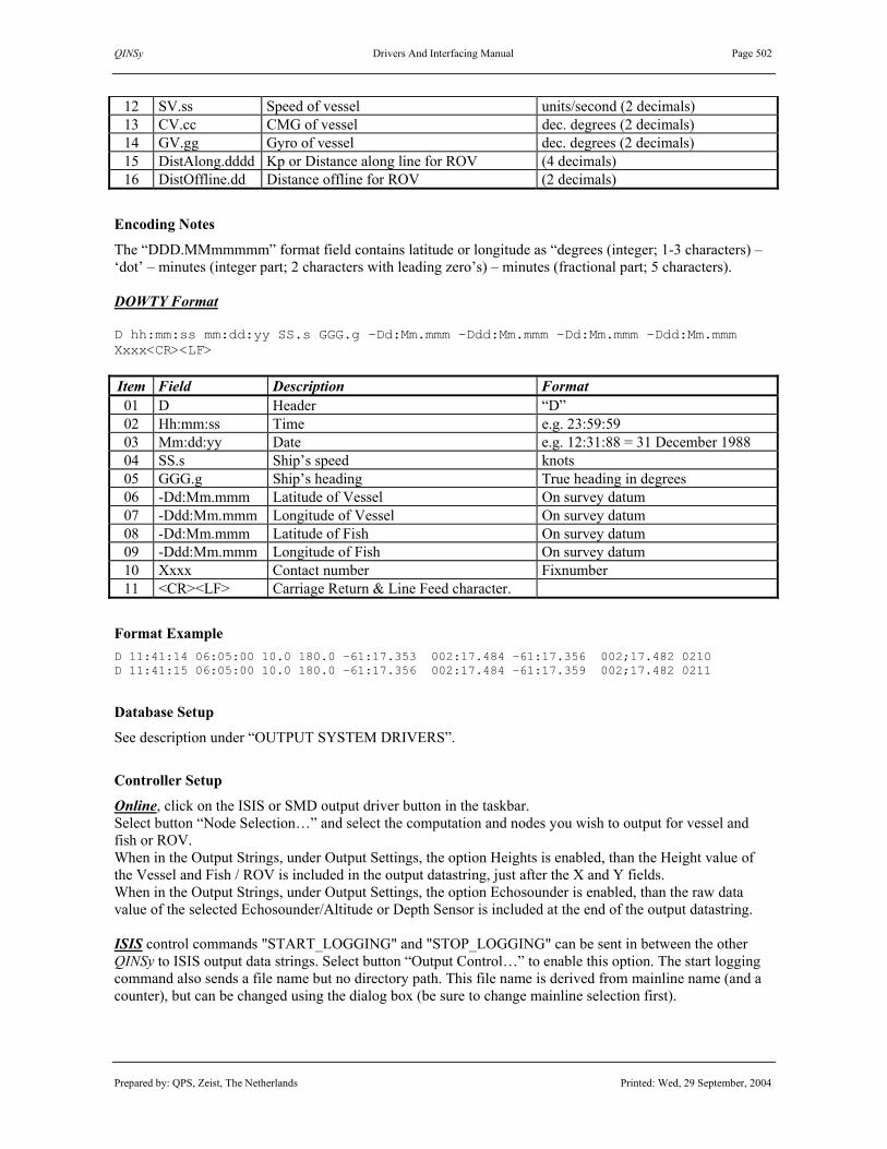
QINSy Drivers And Interfacing Manual Page 502
Prepared by: QPS, Zeist, The Netherlands Printed: Wed, 29 September, 2004
12 SV.ss Speed of vessel units/second (2 decimals) 13 CV.cc CMG of vessel dec. degrees (2 decimals) 14 GV.gg Gyro of vessel dec. degrees (2 decimals) 15 DistAlong.dddd Kp or Distance along line for ROV (4 decimals) 16 DistOffline.dd Distance offline for ROV (2 decimals)
Encoding Notes
The “DDD.MMmmmmm” format field contains latitude or longitude as “degrees (integer; 1-3 characters) – ‘dot’ – minutes (integer part; 2 characters with leading zero’s) – minutes (fractional part; 5 characters). DOWTY Format D hh:mm:ss mm:dd:yy SS.s GGG.g –Dd:Mm.mmm –Ddd:Mm.mmm –Dd:Mm.mmm –Ddd:Mm.mmm Xxxx<CR><LF> Item Field Description Format 01 D Header “D” 02 Hh:mm:ss Time e.g. 23:59:59 03 Mm:dd:yy Date e.g. 12:31:88 = 31 December 1988 04 SS.s Ship’s speed knots 05 GGG.g Ship’s heading True heading in degrees 06 -Dd:Mm.mmm Latitude of Vessel On survey datum 07 -Ddd:Mm.mmm Longitude of Vessel On survey datum 08 -Dd:Mm.mmm Latitude of Fish On survey datum 09 -Ddd:Mm.mmm Longitude of Fish On survey datum 10 Xxxx Contact number Fixnumber 11 <CR><LF> Carriage Return & Line Feed character.
Format Example D 11:41:14 06:05:00 10.0 180.0 –61:17.353 002:17.484 –61:17.356 002;17.482 0210 D 11:41:15 06:05:00 10.0 180.0 –61:17.356 002:17.484 –61:17.359 002;17.482 0211
Database Setup
See description under “OUTPUT SYSTEM DRIVERS”.
Controller Setup
Online, click on the ISIS or SMD output driver button in the taskbar. Select button “Node Selection…” and select the computation and nodes you wish to output for vessel and fish or ROV. When in the Output Strings, under Output Settings, the option Heights is enabled, than the Height value of the Vessel and Fish / ROV is included in the output datastring, just after the X and Y fields. When in the Output Strings, under Output Settings, the option Echosounder is enabled, than the raw data value of the selected Echosounder/Altitude or Depth Sensor is included at the end of the output datastring. ISIS control commands "START_LOGGING" and "STOP_LOGGING" can be sent in between the other QINSy to ISIS output data strings. Select button “Output Control…” to enable this option. The start logging command also sends a file name but no directory path. This file name is derived from mainline name (and a counter), but can be changed using the dialog box (be sure to change mainline selection first).

QINSy Drivers And Interfacing Manual Page 503
Prepared by: QPS, Zeist, The Netherlands Printed: Wed, 29 September, 2004
3.18.34 Naval GPS Data Link (PLO) Input / Output: Output (User-Interface) Driver class type: Output Executable name: DrvOutMultiPositionUI.exe Drivers.io option: NAVSEA Last modified: 2003-Aug-20
Driver Description
Driver for outputting multiple nodes using the Naval GPS Datalink Controller Output format. The user interface makes it possible to select output computation and node, heading and height reference. There are also options to enter a maximum node age and to enable a node status check before outputting the update.
Format Description
All messages start with “^” and end with <CR><LF>. Individual items are separated by a space (“_”).
# Format Item Description Values, Range, Units 01 ^ Header “^” (5E Hex or ASCII 94) 02 XXX_ Heading or CMG TRUE, user interface 03 X_ Time Slot 1 to 8, user interface 04 HH:MM:SS_ Time UTC if available, or system time 05 DD:MM.MMMMN_ Latitude WGS84 if available, or survey datum 06 DDD:MM.MMMMN_ Longitude WGS84 if available, or survey datum 07 X_ GPS Quality PLO input value if available 08 XX_ Satellites Used presently always set to zero 09 XX.XX_ Horizontal DOP PLO input value if available 10 XXXXX.XX_ Elevation see below, user interface 11 XX Checksum 00 to FF 33 <CR><LF> Terminators <CR><LF> (0D Hex, 0A Hex)
Note. The checksum adds the ASCII value of each character starting with the ‘^’ and ending with the space prior to the checksum. Only the lower 8 bits of the checksum are saved and displayed at the end of the line.
Format Example ^025 1 11:07:13 47:41.092200N 122:19.343912W 2 04 2.5 12.37 B4 ^025 2 11:07:13 47:41.092200N 122:19.343912W 2 05 2.5 24.74 BA
Drivers.io Options
Drivers.io command line parameter controls the output data format: “NAVSEA” “Naval GPS Data Link” output format “SUBSEA” “Subsea Telemetry” output format “STATOIL” “Statoil Data Server” output format “GEOLAB” “GeoLab ESP Annotator” output format (continued on next page)

QINSy Drivers And Interfacing Manual Page 504
Prepared by: QPS, Zeist, The Netherlands Printed: Wed, 29 September, 2004
Registry Options [HKEY_CURRENT_USER\Software\QPS\QINSy\7.0\Drivers\PLO\Settings] The following 3 PLO input/output driver setup parameters are read from registry: time separator character (by default ‘:’), UTC GPS time indication (‘U’ or ‘G’, by default ‘U’), and height unit (1 to 14, by default 1). The height units are according to the QINSy unit.dll, 1 is meters, 2 is feet, 3 is yards, 4 is US survey feet. These driver setup parameters are also used by a Naval GPS Data Link (PLO) input driver if this driver has got a command line parameter “REG”. See the description of the Naval GPS Data Link (PLO) input driver.
Database Setup
See description under “OUTPUT SYSTEM DRIVERS”.

QINSy Drivers And Interfacing Manual Page 505
Prepared by: QPS, Zeist, The Netherlands Printed: Wed, 29 September, 2004
3.18.35 Meteo Report Generator (WMO – SYNOP) Input / Output: Output Driver class type: File Output Executable name: DrvMeteoReport.exe Drivers.io options: none Last modified: 2003-01-27
Driver Description
The Weather Report Generator generates a SYNOP report. This is a weather report sent from ships (manned platforms). The weather report is created using sensor data and human observations. A SYNOP report is to be generated on the synoptic hours (00:00Z, 06:00Z, 12:00Z and 18:00Z).
Format Description
Field Format Description Values, Range, Units 0 BBXX Message identifier 1 SHIP Call sign vessel SHIP for navy vessels 2 YYGGIw YY = day of the month,
GG = hour (GMT), Iw = wind indicator
Ix = 1 which means that the wind speed is measured in meters / second
3 99LLLa 99 = position field identifier, LLLa = latitude
Latitude is in tenths of degrees: 35°45’ = 357 07°17’ = 072
4 QLLLLo Q = quadrant LLLLo = longitude
Quadrant: 1 = NE, 3 = SE, 5 = SW, 7 = NW Longitude is in tenths of degrees: 090°03’ = 0900 000°59’ = 0009 179°02’ = 1790
5 IrIxhVV Ir = precipitation indicator Ix = station indicator h = Cloud base height VV = Visibility
Ir = 4 which means that the precipitation is not measured Ix = 1: manned station HVV: see lookup tables
6 Nddff (00fff) N = total cloud coverage dd = wind direction ff = wind speed (< 99 m/s) 00fff = wind speed (> 99 m/s)
N: see lookup table dd: direction in degrees: (085-094) 090° = 09 (175-184) 180° = 18 ff = wind speed in m/s fff = wind speed in m/s When the wind speed exceeds 99 m/s 00fff is outputted and ff is 99.
7 1SnTTT 1 = Air temperature identifier Sn = sign of temperature TTT = air temperature
Sn: 0 positive, 1 negative TTT: in tenths of °C
8 2SnTTTd 2 = Dew point temperature identifier Sn = sign of temperature TTTd = dew point temperature
Sn: 0 positive, 1 negative TTTd: in tenths of °C
9 4PPPP 4 = Atmospheric pressure identifier PPPP = pressure
PPPP: pressure in tenths of millibar (hPa) 1020.5 hPa = 0205 0995.4 hPa = 9954

QINSy Drivers And Interfacing Manual Page 506
Prepared by: QPS, Zeist, The Netherlands Printed: Wed, 29 September, 2004
10 5APPP 5 = Pressure tendency identifier A = tendency character PPP = pressure difference in past 3 hours
A: see lookup table PPP: pressure in tenths of millibar (hPa) 10.5 hPa = 105 -15.4 hPa = 154 (sign is captured in A)
11 7wwW1W2 7 = Weather type identifier ww = present weather type W1 = weather type past 12 hours W2 = weather type past 24 hours
See lookup tables for weather codes
12 8NhClCmCh 8 = Clouds iidentifier Nh = base cloud coverage Cl = low cloud type Cm = medium cloud type Ch = high cloud type
See lookup tables for weather codes
13 9GGgg 9 = Time identifier GG = hours (GMT) gg = minutes
14 222DsDv 222 = Course and speed identifier Ds = course over past 3 hours Dv = speed over past 3 hours
See lookup tables for weather codes
15 0SsTTTw 0 = Water temperature identifier Ss = sign and type of measurement TTTw = temperature
Ss: see lookup table TTTw: in tenths of °C
16 2PPwHHw 2 = Sea wave identifier PPw = wave period HHw = wave height
PPw in seconds HHw in meters
17 3DDw1DDw2 3 = wave direction identifier DDw1 = predominant wave direction DDw2 = secondary wave direction
Ten degrees accurate: 090° = 09 140° = 14
18 4PPw1HHw1 4 = Predominant wave identifier PPw1 = wave period HHw1 = wave height
PPw1 in seconds HHw1 in meters
19 5PPw2HHw2 5 = Secondary wave identifier PPw2 = wave period HHw2 = wave height
PPw2 in seconds HHw2 in meters
20 6IsEEsRs 6 = Accretion identifier Is = cause of accretion EEs = accretion thickness Rs = Situation and trend of accretion
Is, Rs: see lookup tables EEs: thickness in cm
21 ICE csbdz ICE = sea ice identifier C = concentration or arrangement S = Stage of development B = Ice of land origin D = Principal ice edge Z = Situation and trend
See lookup tables
22 8SwTTTb 8 = Wet bulb temperature identifier Sw = sign and type of measurement TTTb = temperature
Ss: see lookup table TTTb: in tenths of °C

QINSy Drivers And Interfacing Manual Page 507
Prepared by: QPS, Zeist, The Netherlands Printed: Wed, 29 September, 2004
Format Example BBXX SHIP 27091 99519 70035 41/99 /0000 10000 20000 40000 54000 70000 8/000 90840 2229/ 00000 20000 3//// 20000
Database Setup
To create a database, which uses this driver, choose the following options. Create a new system. Choose Output System and find the driver named Weather Report Generator (WMO-SYNOP). No other options have to be chosen.
Controller Setup
First time online, select a computation and node for this output driver on the General page.
On the synoptic hours the user is supposed to walk through all the pages and check if all the settings are still valid. If not the settings have to be changed. On the last page a preview can be seen of the report that will be generated. By default the filename is set to the WMO standard (WMOyyyymmddhhmm: date and time) and will update every minute. The default path is the Export folder, which is chosen in the Console.

QINSy Drivers And Interfacing Manual Page 508
Prepared by: QPS, Zeist, The Netherlands Printed: Wed, 29 September, 2004
When the file is generated a message box appears.

QINSy Drivers And Interfacing Manual Page 509
Prepared by: QPS, Zeist, The Netherlands Printed: Wed, 29 September, 2004
3.18.36 NMEA Autopilot Strings Output Driver
3.18.37 NMEA Autopilot Strings (Steered Point) Output Driver
Input / Output: Output Driver class type: Output Executable name: DrvOutAutopilot.exe Drivers.io options: format | factor Last modified: 2001-March-13
Driver Description
Driver for outputting an ASCII NMEA string to an Autopilot, output every QINSy update. The update-rate can be defined as system property in DB Setup. The string may contain either only the APA sentence, or the VHW and ABP sentences, or the BWW and XTE sentences, or the SSA and SSD and SSX sentences for the selected node (The latter sentences are typically used by an E.M.R.I. SEM200 Autopilot and Track Controller). In case the second driver has been selected, the output node used for the calculation will always be the current Steered Node.
Format Description
$--APA,A,A,x.x,a,N,A,A,x.x,a,c--c[*hh]<CR><LF> --: Talker identifier, controlled by Drivers.io command line. A: Status, 'A' = data valid, 'V' = reliable fix not available A: Status, always 'A' x.x Magnitude for cross track error (XTE) a: Direction to steer 'L' = Left, 'R' = Right N: XTE units, 'N' = Nautical miles A: Status: 'A' = Arrival circle entered, always set to 'V' A: Status, perpendicular passed at way point, always set to 'A' x.x: Bearing origin to waypoint a: Magnetic / True, 'M' or 'T' c—c: Destination waypoint ID, set to main line ID hh: Checksum, controlled by Drivers.io command line. $--APB,A,A,x.x,a,N,A,A,x.x,a,c--c,x.x,a,x.x,a,a[*hh]<CR><LF> --: Talker identifier, controlled by Drivers.io command line. A: Status, 'A' = data valid, 'V' = reliable fix not available A: Status, always 'A' x.x Magnitude for cross track error (XTE) a: Direction to steer 'L' = Left, 'R' = Right N: XTE units, 'N' = Nautical miles A: Status: 'A' = Arrival circle entered, always set to 'V' A: Status, perpendicular passed at way point, always set to 'A' x.x: Bearing origin to waypoint a: Magnetic / True, 'M' or 'T' c—c: Destination waypoint ID, set to main line ID x.x: Bearing present position to destination a: Magnetic / True, 'M' or 'T' x.x: Bearing to steer to destination waypoint

QINSy Drivers And Interfacing Manual Page 510
Prepared by: QPS, Zeist, The Netherlands Printed: Wed, 29 September, 2004
a: Magnetic / True, 'M' or 'T' a: Mode indicator (left blank) hh: Checksum, controlled by Drivers.io command line. $--VWH,x.x,T,x.x,M,x.x,N,x.x,K[*hh]<CR><LF> --: Talker identifier, controlled by Drivers.io command line. x.x: True Heading, degrees T: 'T', True x.x: heading, degrees (not used) M: 'M', magnetic x.x: Speed N: 'N', knots x.x: Speed, (not used) K: 'K', km/hr hh: checksum, controlled by Drivers.io command line. $--BWW,x.x,T,x.x,M,c--c,c--c[*hh]<CR><LF> --: Talker identifier, controlled by Drivers.io command line. x.x: True Heading, degrees T: 'T', True x.x: heading, degrees (not used) M: 'M', magnetic c—c: TO waypoint ID, set to main line ID c—c: FROM waypoint ID, set to main line ID hh: checksum, controlled by Drivers.io command line. $--XTE,A,A,x.x,a,N[*hh]<CR><LF> --: Talker identifier, controlled by Drivers.io command line. A: Status, 'A' = data valid, 'V' = reliable fix not available A: Status, always 'A' x.x Magnitude for cross track error (XTE) a: Direction to steer 'L' = Left, 'R' = Right N: XTE units, 'N' = Nautical miles hh: checksum, controlled by Drivers.io command line. For a description of the $--VTG message refer the NMEA GPGGA-GPVTG (Skewed Position).
Format Example $IIVHW,227.1,T,,,0.4,N,,<CR><LF> $IIAPB,A,A,0.0045,R,N,V,A,37.70,T,01,37.70,T,,<CR><LF> $CCAPA,A,A,0.2655,R,N,V,A,50.2,T,Test*3A<CR><LF> $IIVTG,32.0,T,,M,5.00,N,9.26,K<CR><LF>

QINSy Drivers And Interfacing Manual Page 511
Prepared by: QPS, Zeist, The Netherlands Printed: Wed, 29 September, 2004
Format Description EMRI SEM200 Autopilot specific messages (following is an extract from EMRI SEM200 System Description Manual, 8307-3-1.lwp) $PESSA,,XXX.X,,,,,,,,,[*hh]<CR><LF> $PESSA: Proprietary EMRI Steering System Sentence A. XXX.X: Autopilot Course To Steer, in degrees.
It is the linebearing of the current mainline/section. If the current line is curved, it will be the tangential course of the current position on the curved track.
hh: checksum, controlled by Drivers.io command line. All other fields not used. $PESSD,,,RRAD,N,,,,,,R,G,I,T,OPTI,,OPTII[*hh]<CR><LF> $PESSD: Proprietary EMRI Steering System Sentence D. RRAD: Requested Radius Of Turn (Range 0.10 – 9.99 NM) in Nautical Miles.
It is the radius of the current mainline/section . If the vessel is on a straight track, it will be the minimum allowed value of 0.10 NM.
R: Means Remote operating mode. G: Means Gyro steering mode. I: Means Immediate course change mode. T: Means Track control mode. OPTI: Option field I. Set to “2000”, activating the Navigation Computer Control Lamp OPTII: Optional Flag II. Set to “4000” if position is on a curved line/section. Empty field when on a
straight track. hh: checksum, controlled by Drivers.io command line. All other fields not used. $PESSX,XX.X,L,XXX.X,[*hh]<CR><LF> $PESSX: Proprietary EMRI Steering System Sentence X. XX.X: XTE, Cross track Error in meters (Always positive) L: “L” = Steer left, “R” = Steer right XXX.X: HSC, Heading to Steer Command in degrees. It will be the linebearing of the next line/section. hh: checksum, controlled by Drivers.io command line. All other fields not used.
Database Setup
See description under “OUTPUT SYSTEM DRIVERS”.
Controller Setup
Online, except when the “Steered Point” option of this driver has been selected, the appropriate output node must be selected before the driver starts cycling. After going online with the Controller for the first time, select the “Node Output...” option under Settings and select an computation and node for this system. In case of outputting the Steered Node position, the user has to set up also one or more Steered Points.

QINSy Drivers And Interfacing Manual Page 512
Prepared by: QPS, Zeist, The Netherlands Printed: Wed, 29 September, 2004
Drivers.io Options
The first 2 characters of the first command line argument control which talker id is used in the output sentences. Other characters following this talker id that may be used are: A: Output $--APA sentence B: Output $--APB sentence C: Output $--VHW sentence D: Output $--BWW sentence E: Output $--XTE sentence F: Output $--SSA sentence G: Output $--SSD sentence H: Output $--SSX sentence I: Output $--VTG sentence V: Skew output position and it’s derivations like cross track error to real time W: Output only when recording X: Output steered node Y: Mainline ID (not name) Z: Add checksum to sentences The second command line argument is a multiplication factor that will be applied to the cross track error (XTE) before it is output. Use a factor greater than 1 to simulate a high-performance autopilot system.

QINSy Drivers And Interfacing Manual Page 513
Prepared by: QPS, Zeist, The Netherlands Printed: Wed, 29 September, 2004
3.18.38 NMEA GPGGA-GPVTG (Skewed Position)
3.18.39 NMEA GPGGA-GPVTG (Skewed Steered Point)
3.18.40 NMEA GPGGA-GPVTG (Steered Point) Input / Output: Output Driver class type: Output Executable name: DrvOutNMEA.exe Drivers.io options: format | various Last modified: 2001-Nov-16
Driver Description
Driver for NMEA-0183 $GPGGA and $GPVTG output strings. Driver to be used to generate output strings containing position and solution results from the QINSy system. The NMEA output driver has three different types of output modes: 1. Skewed Position position at update time with update time; age is 0 seconds by definition 2. Steered Point position for currently active steered point, determined by the Controller 3. Sounding Datum output height above sounding datum instead of WGS84
Format Description
Each $GPGGA sentence is variable in length, depending on the altitude and age values that are encoded. However, most fields in the string are of fixed length; only altitude and age fields are of variable length. Refer to NMEA 0183- Standard For Interfacing Electronic Devices - Version 2.30 for more information. $GPGGA,hhmmss.ss,ddmm.mmmm,a,dddmm.mmmm,a,Q,nn,h.h,a.a,M,g.g,M,s.s,iiii*hh<CR><LF>
# Format Description Values 01 “$” start character “$” (24 Hex) 02 aaccc address field “GPGGA” 04 hhmmss.ss UTC of position (hours,minutes,seconds) 0…23, 0…59, 0.00…59.99 06 ddmm.mmmm latitude on WGS84 (degrees, minutes) 0…90, 0.00…59.9999 (4 decimals) 08 a latitude on WGS84 (northern or southern) “N” or “S” 10 ddmm.mmmm longitude on WGS84 (degrees, minutes) 0…180, 0.00…59.9999 (4 decimals) 12 a longitude on WGS84 (eastern or western) “E” or “W” 14 Q GPS quality indicator 0 = fix not available or invalid;
1 = GPS SPS mode, fix valid; 2 = DGPS SPS mode, fix valid
16 nn number of satellites in use (≠ in view) 00…12 18 h.h HDOP (horizontal dilution of precision) 20 a.a antenna altitude above WGS84 (not MSL) 22 “M” altitude units (meters) “M” 24 g.g geoidal separation above ellipsoid “0.0” (NOT USED) 26 “M” altitude units (meters) “M” 28 s.s age of differential GPS data 30 iiii differential reference station id “” (NOT USED) 31 “*” checksum field delimiter “*” (2A Hex) 32 hh checksum (XOR from “$” to “*” exclusive) 33 <CR><LF> termination characters <CR><LF> (0D Hex, 0A Hex)

QINSy Drivers And Interfacing Manual Page 514
Prepared by: QPS, Zeist, The Netherlands Printed: Wed, 29 September, 2004
$GPVTG,x.x,T,x.x,M,x.x,N,x.x,K*hh<CR><LF>
# Format Description Values 01 “$” start character “$” (24 Hex) 02 aaccc address field “GPVTG” 04 x.x course over ground (degrees True) 0…360 06 “T” course over ground (degrees True) “T” 08 x.x course over ground (degrees Magnetic) 0…360 10 “M” course over ground (degrees Magnetic) “M” 12 x.x speed over ground (Knots) 14 “N” speed over ground (Knots) “N” 16 x.x speed over ground (Km/hr) 18 “K” speed over ground (Km/hr) “K” 19 “*” checksum field delimiter “*” (2A Hex) 20 hh checksum (XOR from “$” to “*” exclusive) 21 <CR><LF> termination characters <CR><LF> (0D Hex, 0A Hex)
Encoding Notes
QINSy does not encode the geoidal separation and reference station id fields. Latitude and longitude are always given in 4 decimals. The antenna altitude is given with respect to the WGS84 ellipsoid. The age of the differential data will be the age value of the most recent differential correction observation, since each correction observation can have its own age (especially in case of a Sercel HF link). STEERED POINT OUTPUT If the computation fails for the current steered point, its position will be predicted for the number of seconds set in the Filter option in the Controller (default 10 seconds) and then changed automatically to the next steered point. If there is no more steered point left, the last known position will be outputted. With DGPS, the quality indicator Q will be 2 in case everything is OK. Q stays 2 during prediction. If the prediction is caused by No Diff (Stale Corrections), then the number of satellites in use stays the number of satellite observations. If the prediction is caused by e.g. No SVs, then the number of satellites drops to 0. If the prediction time exceeds 10 seconds, Q will change to 1. This 10 seconds is hard-coded in the driver. If the filter prediction time is passed, the Controller will swap to the next steered node. If there is no next steered node defined, output will be the last known position, and Q = 0. If the steered node position comes from an computation that does not contain differential corrections, e.g. with standalone GPS, Q is always 1, also during prediction, and swaps to 0 when prediction time is over. During prediction, the number of satellites will drop to 0. The age of the differential data will always be 0.
Database Setup
See description under “OUTPUT SYSTEM DRIVERS”.
Controller Setup
Online, except when the “Steered Point” option of this driver has been selected, the appropriate output node must be selected before the driver starts cycling. After going online with the Controller for the first time, select the “Node Output...” option under Settings and select an computation and node for this system. In case of outputting the Steered Node position, the user has to set up also one or more Steered Points.

QINSy Drivers And Interfacing Manual Page 515
Prepared by: QPS, Zeist, The Netherlands Printed: Wed, 29 September, 2004
3.18.41 NMEA GPGGA ROV Output Driver
Input / Output: Output Driver class type: Output Executable name: DrvOutGPGGAROV.exe Drivers.io options: Last modified: 2000-Jul-20
Driver Description
Driver for outputting an ASCII NMEA GPGGA string, output every QINSy update. The update-rate can be defined as system property in DB Setup. The latitude and longitude fields in the string refer to the position of the selected “Position Node”. The height field in the output string contains the height difference between a “Reference Node” and a “Target Node”, which could differ from the “Position Node”.
Format Description
Each $GPGGA sentence is variable in length. Refer to NMEA 0183- Standard For Interfacing Electronic Devices - Version 2.30 for more information. $GPGGA,hhmmss.ss,ddmm.mmmmmm,a,dddmm.mmmmmm,a,Q,nn,h.h,a.a,M,g.g,M,s.s,iiii*hh<CR><LF> # Format Description Values 01 “$” start character “$” (24 Hex) 02 aaccc Address field “GPGGA” 04 hhmmss.ss UTC of position (hours,minutes,seconds) 0…23, 0…59, 0.00…59.99 06 ddmm.mmmmmm Latitude on WGS84 (degrees, minutes) 0…90, 0.00…59.999999 (6 decimals) 08 a Latitude on WGS84 (northern or southern) “N” or “S” 10 dddmm.mmmmmm Longitude on WGS84 (degrees, minutes) 0…180, 0.00…59.999999 (6 decimals) 12 A Longitude on WGS84 (eastern or western) “E” or “W” 14 Q GPS quality indicator 0 = fix not available or invalid;
1 = GPS SPS mode, fix valid 16 Nn Number of satellites in use “” (NOT USED) 18 h.h HDOP (horizontal dilution of precision) 20 a.a Height difference 22 “M” Altitude units (meters) “M” 24 g.g Geoidal separation above ellipsoid “” (NOT USED) 26 “M” Altitude units (meters) “M” 28 s.s age of differential GPS data “” (NOT USED) 30 iiii Differential reference station id “” (NOT USED) 31 “*” Checksum field delimiter “*” (2A Hex) 32 hh Checksum (XOR from “$” to “*”
exclusive)
33 <CR><LF> Termination characters <CR><LF> (0D Hex, 0A Hex)
Database Setup
See description under “OUTPUT SYSTEM DRIVERS”.
Controller Setup
Online, the appropriate output nodes must be selected before the driver starts cycling. After going online with the Controller for the first time, select the “Change Nodes...” option in the output driver’s dialog and select the appropriate computation and nodes.

QINSy Drivers And Interfacing Manual Page 516
Prepared by: QPS, Zeist, The Netherlands Printed: Wed, 29 September, 2004
3.18.42 PGS NAV Header (Node Output | Steered Point) Input / Output: Output Driver class type: Output Executable name: DrvOutPGSNavHdr.exe Drivers.io options: STEERED Last modified: 1997-Oct-06
Driver Description
Driver for PGS Nav Header output strings. Driver to be used to generate output strings every QINSy fix update, containing the current line name, the fix number, date and time of position, and the easting and northing from the QINSy system to a Dragged Array onboard PGS OBC vessels. Two output modes are: 3. position for currently selected output position, as set in the Controller’s Options; 4. Steered Point position for currently active steered point, determined by the Controller (Online).
Format Description
There are two different formats for PGS NAV headers: one for Dragged Array (DA); and one for Vertical Cable (VC), which is not implemented yet. Each PGS NAV header field separated by a comma delimiter. Notice the additional trailing comma. The data string is terminated by <CR><LF>. Dragged Array (DA): Item Format Description Length and Alignment
1 cccccccccc… line name at least 10 chars; left-aligned 2 nnnnn… shot point at least 5 chars; right-aligned 3 hh:mm:ss time of position (hours:minutes:seconds) 8 chars (fixed length) 4 dd-mm-yyyy date of position (day-month-year) 10 chars (fixed length) 5 e.e easting (1 decimal accuracy) 6 n.n northing (1 decimal accuracy) 7 <CR><LF> termination characters carriage return | line feed
Format Examples L4-0383 , 845,16:46:39,08-05-1997,499658.1,6838178.4,<CR><LF> L2-1120 , 1386,14:04:10,09-16-1997,522891.3,6681293.7,<CR><LF>
Encoding Notes
The output rate of the PGS header is every fix. The last calculated position will be skewed to the time of fix. Steered Point Output If the computation fails for the current steered point, its position will be predicted for the number of seconds set in the Filter option in the Controller (default 10 s) and then changed automatically to the next steered point. If there is no more steered point left, the last known position will be outputted.
Database Setup
See description under “OUTPUT SYSTEM DRIVERS”.
Controller Setup
Online, except when the “Steered Point” option of this driver has been selected, the appropriate output node must be selected before the driver starts cycling. After going online with the Controller for the first time, select the “Node Output...” option under Settings and select an computation and node for this system. In case of outputting the Steered Node position, the user has to set up also one or more Steered Points.

QINSy Drivers And Interfacing Manual Page 517
Prepared by: QPS, Zeist, The Netherlands Printed: Wed, 29 September, 2004
3.18.43 Pseudo Artemis (Range-Bearing) Input / Output: Output Driver class type: Output Executable name: DrvOutPseudoArtemisUI.exe Drivers.io options: none Last modified: 1998-Jun-17
Driver Description
Driver (with user interface) for outputting Pseudo-Artemis strings, containing a range and bearing between a (fixed) station and the current position, output every QINSy update. The update-rate can be defined as system property in DB Setup. Online, the coordinates of the Pseudo-Artemis station must be entered as easting and northing on the survey datum. Current position can be either the steered node or any node from an existing computation. The output to a DP system can be in four different formats, two binary encoded messages and two ASCII messages. It is also possible to temporarily hold the output. The user can optionally be notified when the output range exceeds predefined limits by enabling an alert option in the drivers dialog window.
Format Description
The following four peripheral output telegram formats are available in the QINSy Pseudo-Artemis driver: 5) KA-BCD(0.1) 7 byte BCD telegram, distance resolution of 1.0m, azimuth resolution of 0.01º. 6) KA-BCD(0.01) 7 byte BCD telegram, distance resolution of 1.0m, azimuth resolution of 0.001º. 7) ASCII-16 16 character ASCII string, distance resolution of 0.1m, azimuth resolution of 0.01º. 8) ASCII-17 17 character ASCII string, distance resolution of 0.1m, azimuth resolution of 0.001º.
KA-BCD(0.1) Byte Description Bit 7-6-5-4 Description Bit 3-2-1-0
1 AZM x 100 AZM x 10 2 AZM x 1 AZM x 0.1 3 0000 AZM x 0.01 4 DIST x 10000 DIST x 1000 5 DIST x 100 DIST x 10 6 0000 DIST x 1 7 1111 1111 KA-BCD(0.1)
Byte Description Bit 7-6-5-4 Description Bit 3-2-1-0 1 AZM x 100 AZM x 10 2 AZM x 1 AZM x 0.1 3 AZM x 0.01 AZM x 0.001 4 DIST x 10000 DIST x 1000 5 DIST x 100 DIST x 10 6 0000 DIST x 1 7 1111 1111
(continued on next page)

QINSy Drivers And Interfacing Manual Page 518
Prepared by: QPS, Zeist, The Netherlands Printed: Wed, 29 September, 2004
ASCII-16
Char Description Values 1 DISTANCE x 10000 2 DISTANCE x 1000 3 DISTANCE x 100 4 DISTANCE x 10 5 DISTANCE x 1 6 DISTANCE x 0.1 7 ‘SPACE’ space character (0x20) 8 AZIMUTH x 100 9 AZIMUTH x 10 10 AZIMUTH x 1 11 AZIMUTH x 0.1 12 AZIMUTH x 0.01 13 ‘SPACE’ space character (0x20) 14 ‘READY’ 1 = data valid, 0 = data not valid 15 <CR> carriage return (0x13) 16 <LF> line feed (0x10) ASCII-17
Char Description Values 1 DISTANCE x 10000 2 DISTANCE x 1000 3 DISTANCE x 100 4 DISTANCE x 10 5 DISTANCE x 1 6 DISTANCE x 0.1 7 ‘SPACE’ space character (0x20) 8 AZIMUTH x 100 9 AZIMUTH x 10 10 AZIMUTH x 1 11 AZIMUTH x 0.1 12 AZIMUTH x 0.01 13 AZIMUTH x 0.001 14 ‘SPACE’ space character (0x20) 15 ‘READY’ 1 = data valid, 0 = data not valid 16 <CR> carriage return (0x13) 17 <LF> line feed (0x10)
Database Setup
See description under “OUTPUT SYSTEM DRIVERS”.
Controller Setup
The node which is to be used for calculating the output values has to be selected in the driver dialog.

QINSy Drivers And Interfacing Manual Page 519
Prepared by: QPS, Zeist, The Netherlands Printed: Wed, 29 September, 2004
3.18.44 Range Site Data Format (Geodesic) Input / Output: Output (User-Interface) Driver class type: Output Executable name: DrvOutRSDFUI.exe Drivers.io options: Last modified: 2004-Mar-19
Driver Description
Driver for US Navy’s Naval Undersea Warfare Center (NUWC) RSDF position, heading and speed data. The Range Site Data Format (RSDF) and Range Site Data Format Geodesic (RSDFG) are used to send data from remote ranges to NUWC Keyport's Range Information Display Center (RIDC) over a high speed data link. The RSDF input driver can be used together with the RSDF output driver to buffer the input data stream, insert and convert position records and/or change the RSDF format, and output the updated data stream.
Format Description
See for more information on the Range Site Data Format (Geodesic), the documentation from the NUWC.
Encoding Notes
The output format for position records depends on the selected output driver. If an RSDF input driver is running, it will buffer incoming records and the RSDF output driver will operate in “pass through” mode. If the RSDF output driver is operating in “pass through” mode, any position present in the records that are passed through is converted to WGS84 latitude, longitude, altitude or in tangent plane coordinates (X, Y, Z) depending on the format with which the output driver is started. If positions are both passed through and modified by QINSy, the latter positions will prevail. The modified position will then be put in a PG record format to replace the original position, even if this was incoming in another position record format. With the driver in “pass through” mode, all generated positions are added to the received blocks. This means that a position created on 2003-07-18 15:01.45 will be added to a block for e.g. 2003-07-18 15:02.00 with a timing offset of 550 ms. No blocks will be created, even if incoming blocks are missed. In the “output only” mode, blocks will be generated at a frequency depending on the update rate as entered in the database. Records that are either always encoded or can be encoded by the RSDF-RSDFG output driver are:
• SR - Run Security • HR - Run ID Header • MK - Mark Information • HS - Run Statistics Header • PP - Processed PSK Data • PC - Processed Cinesextant Data • PG - Processed GPS • PR - Processed Radar • TC - Trailer Comments • ED - End Record • BC - Block Byte Count • CS - Checksum Information

QINSy Drivers And Interfacing Manual Page 520
Prepared by: QPS, Zeist, The Netherlands Printed: Wed, 29 September, 2004
Encoding Notes (continued)
More information on encoding can be found in the QPS “RSDF I/O Driver Detailed Design” document. SR record. The “security classification” field is obtained from the “survey type” field in the “general” category of the database. Record is not modified if the driver is operating in “pass through” mode. HR record. The “sequence number” field contains QINSy sequence number, the “mark” field contains first part of object name, the “mod” field contains second part of object name, the “register” field contains third part of object name, the “run plan” field contains QINSy line name. An underscore character (“_”) should separate parts of object name in the QINSy database. Not modified if operating in “pass through” mode. MK record. All fixed nodes present in the database will be outputted as MK records at the start of a run. HS record. The “date” and “time” fields are filled with UTC or local time. The “security class” field is based on the contents of the “survey type” field in the “general” category of the database setup program. The “point count A” field contains an incrementing output counter since the output driver was started. “event count B” and “signals” fields are always empty. Record is not modified if driver is operating in “pass through” mode. PG record. Default record to output positions computed by QINSy. Type can be changed in registry. TC record. Trailer comment is passed through, altered (or added) depending on the driver UI option. ED record. By default, the end of data signifier is “9999”, but this number can be changed in registry. BC or CS record. The block byte count and checksum record is always updated by QINSy. By default, the “BC” record is used, but this can be replaced by the “CS” record, by changing the appropriate registry key.
Registry Options [HKEY_CURRENT_USER\Software\QPS\QINSy\7.0\Drivers\RSDF\Settings]
Registry Key Default Records Description, Values Year Modulus 1900 HS year number to add to decoded year value Time Frame 1 HS block time not used (0), UTC (1) or local time (2)
Timing Offset 0 PF,PG,PP,PR offsets not used (0), to be added (1) or subtracted (2) Length Unit 4 PF,PG,PP,PR meters (1), int. feet (2), yards (3), US survey feet (4)
Convert Heights 0 PF,PG,PP,PR update height information during conversions Convert Courses 0 PF,PG,PP,PR update course information during conversions Position Record PG PF,PG,PP,PR default record type to output QINSy positions
CheckSum Record BC BC,CS default record type to end a block of records Object Separator “_” HR default character to separate object name
Note. If HS Time Frame is set to 2, then HS block times are supposed to be in the local system time of the computer on which QINSy is running. Timetags are converted from UTC using the local time zone setting. Note. The Timing Offset key is also used by the RSDF input driver, where 0 and 2 have different meanings. Since the RSDF output driver always computes a timing offset, only the registry value 1 is important. Note. The first registry keys can be changed online using the “Formats...” dialog. See online options below.

QINSy Drivers And Interfacing Manual Page 521
Prepared by: QPS, Zeist, The Netherlands Printed: Wed, 29 September, 2004
Database Setup
See description under “OUTPUT SYSTEM DRIVERS”. Note. Only one output system has to be defined per output COM port. Output nodes are selected online.
Online Setup
The “Add” and “Remove” buttons can be used to add or remove an item (position). Whether an item is actually used to output a “PG” record, depends on the item checkbox. “ID” is the object ID that is used in the “PG” record. “Computation” and “Node” determine the position that is used for the “PG” record. The selected “Orientation” angle will be a grid bearing in case of the RSDF output driver and a true bearing in case of the RSDFG output driver. The “Height” option can be used to output for example 0.0 heights.
Online Options
The “Save” items button can be used to save the selected items to registry during a QINSy online session. The output of record blocks can be delayed for a couple of seconds, so that QINSy positions can be inserted in the proper block. This value should reflect the maximum latency of the input record blocks that can be expected when the output driver is operating in “pass through” mode. One can use 0 in “output only” mode.

QINSy Drivers And Interfacing Manual Page 522
Prepared by: QPS, Zeist, The Netherlands Printed: Wed, 29 September, 2004
The Start-Stop options are only available when the driver is operating in “output only” mode. When the manual option is selected, a “Start-Stop Run” button will appear on the output driver window, that can be used to start and stop a run. When the output driver is operating in “pass through” mode, these options are not used and the start run records and stop run records will be obtained from the RSDF input driver buffer.
Online Options
The first four options are also used for RSDF / RSDFG input drivers. If a selection is changed, then running input drivers will apply them immediately, so there is no need to restart an online If a selection is changed, then running input drivers will apply them immediately, so there is no need to restart an online QINSy session. The Year Modulus indicates which value is to be added to the year values in HS records, i.e. 0, 1900 or 2000. The Time Frame indicates whether HS timetags are encoded (and decoded) as UTC or local system time. Presently, Length Unit can be meters, international feet, international yards or US survey feet. Timing Offset values in PF,PG,PP,PR records can be disregarded, added to or subtracted from the HS block timetags. The last two options are only available if the RSDF output driver is operating in “pass through” mode and if the input format is different from the output format. Heights (Depth / Altitude) and Courses can be updated during the datum conversions, according to the selections in the driver window, or can be copied from the input data.

QINSy Drivers And Interfacing Manual Page 523
Prepared by: QPS, Zeist, The Netherlands Printed: Wed, 29 September, 2004
3.18.45 Seabat 8000 Series UTC Synchroniser
3.18.46 Sercel Axyle UTC Synchroniser Input / Output: Output Driver class type: Output Executable name: DrvSeabatSynch.exe Drivers.io options: AXYLE Last modified: 1999-Dec-10
Driver Description
Driver for synchronisation of a Reson Seabat 8000 series multibeam or Sercel Axyle AP1 to the QINSy UTC time. When Pulse-Per-Second (PPS) support is used, timing can be very accurate, otherwise synchronisation is done with the system time of the QINSy computer. Driver obtains the current PPS time, formats the string and outputs the data to the serial port. Timestamp is valid for the first character of the output string. Note: no PPS is required in Axyle mode when used in combination with the Axyle 0 message position driver.
Format Description Seabat $UTC,yyyymmdd,hhmmss.ssss<CR><LF> 0123456789012345678901234 Item Format Description Values,Units
1 “$UTC” header identifier fixed string 2 yyyymmdd date of sensor message yyyy = year, mm = month, dd = day 3 hhmmss.ssss time of sensor message hh = hours, mm = minutes, ss.ssss = seconds 4 <CR><LF> carriage return – line feed ASCII 13 – ASCII 10
Format Description Axyle 000 DATE 048,15:05:30<CR><LF> 0123456789012345678901234 Item Format Description Values,Units
1 000 AP1 receiver identifier fixed string [addresses all recievers] 2 ddd date Day of the year , 1 to 365 (3character) 3 HH:MM:SS time of sensor message hh = hours, mm = minutes, ss.ssss = seconds 4 <CR><LF> carriage return – line feed ASCII 13 – ASCII 10
Interfacing Notes
A simple one-way wired RS-232 cable is enough. However a bi-directional cable is more practical.
Drivers.io Options
AXYLE: Format will be set to Axyle type. Data will be output exactly on the second.
Database Setup
For the Axyle output, it is best to setup the update time at 30 seconds. In this case, every 30 seconds a time sync message is sent to the AP1 receiver. See further description under “OUTPUT SYSTEM DRIVERS”.

QINSy Drivers And Interfacing Manual Page 524
Prepared by: QPS, Zeist, The Netherlands Printed: Wed, 29 September, 2004
3.18.47 Simrad ADP70X (Position and Waypoints) Input / Output: Input Driver class type: Output/UI Executable name: DrvOutSimradADP70X.exe Drivers.io options: None Last modified: 2004-Aug-17
Driver Description
Driver is used to send position information and waypoints to a Simrad ADP-70X Dynamic Positioning (DP) system. The position information is sent every computation update to the DP. Although the output telegram can contain two positions, a primary and a secondary position, only the primary position is filled. The positions that are sent to the DP are all in UTM, user-definable zone. The conversion from survey datum is done in the driver so there is no need to have the UTM projection defined in the geodetic parameters of the template database.
Format Description
The outputted messages are in a binary form, the digits are BCD (Binary Coded Decimal) formatted. One byte is split into 2 four-bit pieces. The four bit part is be used to place one binary digit in, representing a number between 0 and 9. One byte contains two BCD Digits.
POSITION TELEGRAM:
BYTE Description Values, Range, Units
01 Telegram Id Always 11 02 Number of Nav systems Always 1 03 Nav System Id Always 23 (GPS) 04 Status Always 1 (Pos update)
05-09 UTM North (MSB Byte 05) UTM position, zone user definable 10 - 14 UTM East (MSB Byte 10)
15 CRC Checksum XOR over bytes 01-14 16 END OF REPORT Always 255 (11111111 binary)
Note: This is a shorter version of the 27-byte original telegram that contains space for 2 positions. Refer to manual for full details on this telegram. WAYPOINT TELEGRAM: One waypoint telegram can contain up to 10 waypoints. If more waypoints are to be transferred then this is possible by splitting the waypoints in batches and transmitting them to the DP batch by batch. The table number in the telegram is incremented after every batch and identifies the batch. BYTE Description Values, Range, Units
01 Telegram Id Always 04 02 Number of Waypoints 1 – 10 03 Table Number
04-21 Track name (ASCII) CR Terminated 22-26 UTM North Point 1 Start 27-31 UTM East 32-33 Vessel wanted heading Not used Always 0D-01

QINSy Drivers And Interfacing Manual Page 525
Prepared by: QPS, Zeist, The Netherlands Printed: Wed, 29 September, 2004
34-35 Vessel Wanted speed Not used Always 0D-01 point 1 End 36-161 Same as above point 2- 10
162 CRC Checksum XOR over bytes 01-161 163 END OF REPORT Always 255 (11111111 binary)
Note: Depending on the number of waypoints the telegram may be shorter. The CRC and EOR must always follow after the last waypoint.
Interfacing Notes
Cable details are unknown, please refer to DP manual.
Database Setup
See description under “OUTPUT SYSTEM DRIVERS”.
Controller Setup
The Update Rate depends on the update rate of the computation. If the computation updates at 1 Hz then the output will also be at 1 Hz. The appropriate output node must be selected before the driver starts cycling. After going online with the Controller for the first time, select the “Computation Setup...” menu under Settings and select group item “Shortcuts” and item “Output nodes”. Select the output driver and the required node. Note: The simrad DP always expects the COG (Center Of Gravity) of the vessel.
User Interface
The main dialog of this driver and the Select menu:

QINSy Drivers And Interfacing Manual Page 526
Prepared by: QPS, Zeist, The Netherlands Printed: Wed, 29 September, 2004
Output Threshold: If enabled the driver can keep track of the positions sent to the DP, if these positions remain the same for the entered amount of cycles, all output is suspended until the position changes again. Send Waypoints: With this option the user can send the the current mainline, whether it is a route, point or line to the DP. UTM Zone: This option allows setting the specified UTM zone. All output positions are converted to the user selected UTM zone.

QINSy Drivers And Interfacing Manual Page 527
Prepared by: QPS, Zeist, The Netherlands Printed: Wed, 29 September, 2004
3.18.48 Simrad S90 Telegram Output Driver Input / Output: Output Driver class type: Output Executable name: DrvOutSubspection.exe Drivers.io options: S90 Last modified: 2000-Jun-02
Driver Description
Driver (with user interface) for outputting the Simrad S90 position telegram, output every QINSy update. The update-rate can be defined as system property in DB Setup. The string contains a position in lat, lon on survey datum for the selected node, and a ROV depth for the selected bathy system.
Format Description
ASCII String, terminated by a carriage return linefeed.
S90 Format Example
$TLS90,130502,07263634,5157.4572N,00330.7400E,000000000.0,0000000.0,00,00000.0000B,3,A,00.0,000.0 For format description see the EM3000 Datagram formats document.
Database Setup
See description under “OUTPUT SYSTEM DRIVERS”.

QINSy Drivers And Interfacing Manual Page 528
Prepared by: QPS, Zeist, The Netherlands Printed: Wed, 29 September, 2004
3.18.49 Simrad DP Force Output Driver Input / Output: Input Driver class type: Terminated <LF> Executable name: DrvOutSimradDPForce.exe Drivers.io options: Last modified: 2002-June-13
Driver Description
In order to help the Simrad DP control the vessel position as good as possible QINSy will transmit cable forces on a separate port using this driver and the position of the grab ROV reference node.
Format Description
The $PQPSC message is a proprietary NMEA0183 sentence, $ PQPSC – Forces on the horizontal plane (X, Y) for three points. $ PQPSC,hh,xxxx,yyyy,hh,xxxx,yyyy,hh,xxxx,yyyy[*hh]<CR><LF> The output message of the grab ROV position is a standard NMEA $GPGGA message. See the Sercel 103 NMEA Position ($GPGGA) for more information on the $GPGGA format.
Field Format Description Values, Range, Units 01 $ Start character 24 HEX 02 PQPSC Identifier 03 Hh Cable identifier Always 01 04 Xxxx Force hoisting winch fore X axis KN 05 Yyyy Force hoisting winch fore Y axis KN 06 Hh Cable identifier Always 02 07 Xxxx Force hoisting winch aft X axis KN 08 Yyyy Force hoisting winch aft Y axis KN 09 Hh Cable identifier Always 03 10 Xxxx Force umbilical X axis KN 11 Yyyy Force umbilical Y axis KN 12 *hh Checksum XOR 13 <CR><LF> Termination characters 0D 0A HEX
Format Example $PQPSC,01,0300,0400,02,0100,0200,03,0500,0600*6A $GPGGA,172452.99,5224.337,N,00452.979,E,9,8,1,35,M,82,M $PQPSC,01,0200,0400,02,0100,0200,03,0500,0400*69 $GPGGA,172452.99,5224.337,N,00452.979,E,9,8,1,35,M,82,M
Decoding Notes
No decoding for the cable forces direct output from generic observation. No data conversions.
System Configuration
The Update Rate is user defined in the Database Setup program. The observations should be selected in the corresponding combo boxes. The output of the grab position is defined by choosing the computation and node of the grab ROV reference node.

QINSy Drivers And Interfacing Manual Page 529
Prepared by: QPS, Zeist, The Netherlands Printed: Wed, 29 September, 2004
Database Setup
See description under “OUTPUT SYSTEM DRIVERS”.
User Interface
The user interface of this driver:

QINSy Drivers And Interfacing Manual Page 530
Prepared by: QPS, Zeist, The Netherlands Printed: Wed, 29 September, 2004
3.18.50 Statoil Data Server Format
Input / Output: Output Driver class type: Output Executable name: DrvOutSubseaTelemetry.exe Drivers.io options: none Last modified: 2000-April-19
Driver Description
Driver for output of position(s) and heading(s) to the Statoil data server. One may manually select which node(s) are being used to generate the output.
Format Description
STATOIL DATA SERVER FORMAT: $G2,153229.0,591096.6,6746122.7,1,0,85 $G1,153229.0,590858.1,6746168.3,1,0,273.9 $G3,153229.0,591073.1,6746133.8,1,0,178.9
# Format Description Values, Range, Units 01 $Gn Identifier with vessel id ‘n’ n = 0 – 9 02 ,hhmmss.ss Time 03 ,eeeeee.e Easting UTM 04 ,nnnnnnn.n Northing UTM 03 ,z UTM Zone number between 1 – 60 04 ,d Depth metres, -ve below water 05 ,b.b Heading degrees, True. N.B system uses 0 degrees = north
and west = +90 degrees, i.e. the opposite rotation convention from normal survey conventions
06 <CR><LF> Carriage Return Line Feed
Database Setup
See description under “OUTPUT SYSTEM DRIVERS”.

QINSy Drivers And Interfacing Manual Page 531
Prepared by: QPS, Zeist, The Netherlands Printed: Wed, 29 September, 2004
3.18.51 Subsea Telemetry Format Output Input / Output: Output Driver class type: Output Executable name: DrvOutSubseaTelemetry.exe Drivers.io options: none Last modified: 2000-April-19
Driver Description
Driver for output of position(s) and heading(s) to the Subsea telemetry system. One may manually select which node(s) are being used to generate the output.
Format Description
Refer to paragraph 3.2.47 for a full format description.
Interfacing Notes
A simple one-way wired RS-232 cable is enough. However a bi-directional cable is more practical.
Database Setup
See description under “OUTPUT SYSTEM DRIVERS”.

QINSy Drivers And Interfacing Manual Page 532
Prepared by: QPS, Zeist, The Netherlands Printed: Wed, 29 September, 2004
3.18.52 Syledis Y/X Position (Fault Quality) (Node Output | Steered Point)
3.18.53 Syledis Y/X Position (Quality) (Node Output | Steered Point) Input / Output: Output Driver class type: Output Executable name: DrvOutPosition.exe Drivers.io options: STEER Last modified: 2004-Aug-09 SYL | FQ | Q | ADCP | SNGLL | T | G
Driver Description
Driver to output position results (Northing/Easting on Survey Datum) in a Syledis Message format. The position is always skewed to the time of output. The driver supports two types of output modes: position for currently selected output node, as set in Controller’s Node Output; Steered Point position for currently active steered node, determined by the Controller (Online).
Format Description
The driver supports two formats, one with Y/X followed by a ‘Fault’ field and a ‘Quality’ field, e.g. to a Cegelec DPS 901 system, and one with Y/X followed by a ‘Quality’ field only. The output ASCII string is terminated by Carriage Return and Line Feed characters. The fields in the string are of fixed length. Format (Fault Quality) - length of output data string : 40 characters (including <CR><LF). _YSNNNNNNN.N_XSEEEEEEE.E_F000_Qsww____<CR><LF> • _ Space Character • Y Northing identifier (fixed character "Y") • X Easting identifier (fixed character "X") • S Sign, "+" or "-" • NNNNNNN.N UTM Northing of the selected node or Steered Node • EEEEEEE.E UTM Easting of the selected node or Steered Node • F000 Fault Field identifier (fixed characters; not used) • Q Quality identifier (fixed character "Q") • s Sensor number (registry setting, default “1”) • ww System link weight (registry setting, default “10”) Example: “ Y+2946016.4 X+0416104.0 F000 Q110” Format (Quality) - length of output data string : 35 characters (including <CR><LF). _YSNNNNNNN.N_XSEEEEEEE.E_Qfaaabbb<CR><LF> • _ Space Character • Y Northing identifier (fixed character "Y") • X Easting identifier (fixed character "X") • S Sign, "+" or "-" • NNNNNNN.N UTM Northing of the selected node or Steered Node • EEEEEEE.E UTM Easting of the selected node or Steered Node • Q Quality identifier (fixed character "Q") • f Filtering strictness (registry setting, default “0”) • aaa Distance Root-Mean-Square (meters; see registry settings) • bbb Line of Position Mean Error (meters; see registry settings) Example: “ Y+2946016.4 X+0416104.0 Q0005005”

QINSy Drivers And Interfacing Manual Page 533
Prepared by: QPS, Zeist, The Netherlands Printed: Wed, 29 September, 2004
Encoding Notes
If the ‘Steered Point’ mode has been selected and the computation fails for the current steered point, its position will be predicted for the number of seconds set in the Filter option in the Controller (default 10 seconds) and then changed automatically to the next steered point. If there is no more steered point left, the last known position will be outputted. To limit the output to a certain position age, add ‘AGE’ to the Drivers.io file (see below). In this case, the drivers stops outputting data if the position results are older that 'N' times the output system update rate, where ‘N’ is the ‘Age factor’ from registry (see below). The sensor number will not by default contain the Computation Id of the selected node or Steered Node anymore, but has been fixed to “1” because a Cegelec DP 901 did not accept any other number. The DRMS value is computed as sqrt(σE²+σN²) and the LPME value is just the standard deviation for the horizontal position, taking correlation into account. Both values are by default 1-sigma = 68%.
Registry Settings
If the output drivers has been started once, some registry variables are available under the following key: [HKEY_CURRENT_USER\Software\QPS\QINSy\7.0\Drivers\DrvOutPosition\Settings] "Age factor" default 5 multiplication factor for system update rate, to compute maximum age. "Quality factor" default 1 0: set zero DRMS LPME values; 1: 1-sigma values; 2: 2-sigma values. "Sensor number" default 1 1-4: fixed sensor number; 0: replace sensor number by computation id. "Link weight” default 10 10-99: system link weight (see NGL User Manual for more info). "Filter strictness" default 0 0-9: filter strictness value (see Alstom Manual, Cegelec Manual).
Drivers.io Options
Command line parameters for use in the Drivers.io file are as follows. “STEER” will use the Steered Node position, otherwise the position is used for the node that is selected in the Controller’s Node Output settings. “SYL” will start DrvOutPosition in Syledis mode. “ADCP”, “SNGLL” or another header will start the driver in ADCP mode. See “ADCP Lat/Lon Position” and “ADCP X/Y Position” drivers for more information. “FQ” will start DrvOutPosition with the “(Fault Quality)” format, “Q” will output the “(Quality)” format.
Database Setup
See description under “OUTPUT SYSTEM DRIVERS”.
Controller Setup
Online, except when the “Steered Point” option of this driver has been selected, the appropriate output node must be selected before the driver starts cycling. After going online with the Controller for the first time, select the “Node Output...” option under Settings and select an computation and node for this system. In case of outputting the Steered Node position, the user has to set up also one or more Steered Points.

QINSy Drivers And Interfacing Manual Page 534
Prepared by: QPS, Zeist, The Netherlands Printed: Wed, 29 September, 2004
3.18.54 Syntrak 480 Output
3.18.55 Syntrak 480 Output (Steered) Input / Output: Output Driver class type: Terminated <LF> Executable name: DrvOutSyntrak480.exe Drivers.io options: STEERED Last modified: 2003-April-24
Driver Description
This driver sends a message to the Syntrak 480 system whenever a fix is generated in QINSy. The message contains information about the fix: number, date, time, position, water depth, course and speed. There is a delay between the fix and sending the message of minimal 100 milliseconds. The position being sent is the node selected in Node Output… When the STEERED option is used the steered node position will be used. The water depth is the depth the first found echo sounder system has sent to the QINSy system. So if more than one echo sounder is available to take data from the first one in the list will be used to fill the depth field.
Format Description
The format of the output string is of fixed length. Numerical fields will be padded with zero’s (ASCII 48), ASCII fields will be padded with “-“ characters to fit the defined field length. The output message will be built up as follows:
Field Format Values, Range, Units Format 0 Master Block ID $1 A2 1 Record Length Length of Remaining Message I4 2 Program Revision 0001 A4 3 Shot Switch 03=Online I2 4 Shot Time (hhmmssyyyymmdd---) UTC Time A17 5 Shot Number I6 6 Line Id Current line name (----A12793P1-
038) A16
7 CRP Latitude Decimal Degrees (+=North / -=South) F11.6 8 CRP Longitude Decimal Degrees (+=East / -=West) F11.6 9 Water Depth Meters F6.1 10 Master Gyro Degrees F5.1 11 Master CMG Degrees F5.1 12 Master Speed Knots F4.1 13 CR LF CR LF 2
Format Example $109900010312462620030424---000000----------Noname0047.6666680003.0972250012.3045.0044.900.1<CR><LF> $109900010312462720030424---000002----------Noname0047.6666690003.0972250012.3045.0044.900.1<CR><LF> $109900010312463220030424---000003----------Noname0047.6666700003.0972280012.3045.0044.900.1<CR><LF> $109900010312463720030424---000004----------Noname0047.6666720003.0972300012.3045.0044.900.1<CR><LF>

QINSy Drivers And Interfacing Manual Page 535
Prepared by: QPS, Zeist, The Netherlands Printed: Wed, 29 September, 2004
3.18.56 Tug Manager
Input / Output: Output Driver class type: Output Executable name: DrvOutXXXManager.exe Drivers.io options: Last modified: 2004-July-09
Driver Description
Driver to output tug, rig and anchor positions to the QPS Tug Display. User can add a tug and set its nodes for the stern roller and the GPS antenna through the properties dialog. The target is retained from the anchor planning in the controller. The driver supports multiple tugs. It is important to give each tug a unique ID so that the Tug Displays on the tugs can filter out the data meant for that tug. By checking / unchecking the checkboxes in front of the tugs data can be send (or not). Beside tug information also information can be send to the tug display regarding the position of the rig or barge and the anchor positions. The output interval of all messages can be user definable to save bandwidth on the radio link.

QINSy Drivers And Interfacing Manual Page 536
Prepared by: QPS, Zeist, The Netherlands Printed: Wed, 29 September, 2004
Output options The driver can output various messages. The output frequency of the various message types may be changed by the user. Usually it will be a trade-off between available radio bandwidth and refresh frequency. Press the “Output…” button to activate the output options dialog (see below).
Description of available options:
• Enable Serial output Switch on/off generation of serial data. Can be used to disable the output of the driver.
• Send Delay The send delay is the amount of time that the driver will wait between sending two consecutive messages. This delay is introduced to give the radio modem some time to recover after sending a string. For example when new node results are available for multiple tugs at the same time then multiple TUG messages will be send. Between the PQTUG messages the driver will insert a delay.
• Output Tug info Can be either: off, every user definable second or every position update. If the “Use compressed PQTUC) Format” option is used (this is the default) then the much smaller PQTUC message is sent instead of the legacy, bulkier (but more precise) PQTUG message. In order to save bandwidth in multiple tug Anchor management we advice the usage of PQTUC.
• Output Rig Info Can be either: off, every user definable second or every position update. This will change the output of the PQRIG message. Can be used to visualize a rig or barge shape onto the tug display(s).
• Output Anchor Info Can be either: off or Changes + Time interval. Single PQANC message is generated whenever a change in anchor state occurs (e.g. it is dropped or picked up). All anchor are transmitted every user defined number of seconds. This is useful for (re-)starting tug displays or whenever an anchor message is not received properly when it changed. . This message can be used to visualize the actual anchor positions onto the tug display(s). Anchor info can only be output when Rig info is also output at the same timer. This is because the tug display needs the rig positions to calculate one end of the anchor wire.

QINSy Drivers And Interfacing Manual Page 537
Prepared by: QPS, Zeist, The Netherlands Printed: Wed, 29 September, 2004
Format Description All ASCII strings are comma separated and terminated by a <CR><LF> pair. They all contain a checksum. PQTUG Contains survey datum/grid positions and tug/anchor state info for one tug. Eastings and northings are specified to a 1/100 survey unit accuracy. $PQTUG,ID1,ID2,E1,N1,E2,N2,E3,N3,E4,N4,HDG,SOG,COG,R,B,STATE,UNIT,FIXCS<CRLF>
$PQTUG: Tug manager header ID1 Tug ID ID2 Anchor ID E1,N1: Position of reference point on tug E2,N2: Position of GPS antenna on tug E3,N3: Position of stern roller on tug E4,N4: Planned position of anchor HDG: Heading of tug SOG: Speed over ground of tug COG: Course over ground of tug R,B: Range and bearing from stern roller to planned position STATE: Anchor state, Free, Transit or Dropped UNIT: Survey unit as defined in DB Setup FIX: Current Fix number CS: Checksum Example $PQTUG,1,1,390867.36,10146623.09,390871.95,10146619.24,390859.70,10146629.52,384577.34,10152438.35,130.00,5.14,130.02,8556.31,312.76,1,1,418*51
PQTUC Contains survey datum/grid position and tug/anchor state info for one tug. Because it holds one reference position and for the others offsets with respect to the ref. Position it is much more compressed. Eastings Northings and delta Eastings/Northings are specified to 1 survey unit. One exception is the delta Easting/Norting of the planned position this is specified in 1/10 survey unit. $PQTUC,ID1,ID2,E1,N1,ER1,NR1,ER2,NR2,ER3,NR3,HDG,SOG,COG,STATE,UNIT,FIXCS
$PQTUC: Tug manager header ID1 Tug ID ID2 Anchor ID E1,N1: Position of reference point on tug ER1,NR1: Position og GPS antenna on tug (Offsets from ref point) ER2,NR2: Position of stern roller on tug (Offsets from ref point) ER3,NR3: Planned position of anchor (Offsets from ref point) HDG: Heading of tug SOG: Speed over ground of tug COG: Course over ground of tug STATE: Anchor state, Free, Transit or Dropped UNIT: Survey unit as defined in DB Setup FIX: Current Fix number CS: Checksum

QINSy Drivers And Interfacing Manual Page 538
Prepared by: QPS, Zeist, The Netherlands Printed: Wed, 29 September, 2004
Example $PQTUC,1,1,390505,10146927,5,-4,-8,6,-5928,5511,130,5.1,130,1,1,400*7D
PQRIG Contains survey datum/grid position info for one rig. Eastings and northings are specified to a 1/100 survey unit accuracy. $PQRIG,ID1,E1,N1,HDG,SOG,COG,UNIT,FIXCS
$PQRIG: Tug manager header ID1 Object ID E1,N1: Position of reference point on rig HDG: Heading of rig SOG: Speed over ground of rig COG: Course over ground of rig UNIT: Survey unit as defined in DB Setup FIX: Current Fix number CS: Checksum Example $PQANC,1,349575.10,10144038.89,0.00,0.00,0.03,1,628*7E PQANC Contains survey datum/grid position info for one anchor. Eastings and northings are specified to a 1/100 survey unit accuracy. $PQRIG,ID1,ID2,E1,N1,NAME,STB,FWDCS
$PQANC: Tug manager header ID1 Anchor ID ID2 Tug ID that is handling this anchor E1,N1: Drop Position (zero if in transit or free) NAME: Anchor name STB: Offset X direction of anchor winch on board rig FWD: Offset Y direction of anchor winch on board rig CS: Checksum Example $PQANC,4,2,1,1,387786.33,10149210.52,S1,10.00,18.00*1
Database Setup
See description under “OUTPUT SYSTEM DRIVERS”.

QINSy Drivers And Interfacing Manual Page 539
Prepared by: QPS, Zeist, The Netherlands Printed: Wed, 29 September, 2004
Interfacing Notes The tug manager is developed in conjunction with the Tug Display. In operation it will probably make use of a two way radio connection. On the tug position and heading data will be send to the rig or barge. If this is a GGA and HDT message each updating once a second it is adviced to us the combined NMEA GGA / HDT driver. On the barge the tug data is send back to the tugs. If there is a two way radio link you will get for each tug a position / heading on an I/O port and for all the tugs one I/O port for the tug manager output driver. This data then needs to be splitted to each of the separate radio links to the tugs.
Tug 1 Rig
Tug 2
Pos / Hdg
Pos / Hdg
$PQTUG
$PQTUG

QINSy Drivers And Interfacing Manual Page 540
Prepared by: QPS, Zeist, The Netherlands Printed: Wed, 29 September, 2004
3.18.57 VisualWorks Event Output Input / Output: Output Driver class type: Output <CRLF> Executable name: DrvOutEvent Drivers.io options: NONE Last modified: 2002-Aug-21
Driver Description
Driver to output an ASCII string containing date, time, event code and comment to the VisualSoft made VisualWorks software. All in formation present in the string is taken from the data as generated by the event generation driver
Format Description
The ASCII string contains the fields shown in the table below separated by a comma and terminated by a Carriage Return and a Line Feed. 21/08/2002,13:17:14,FS,Start of Freespan 1
Field Format Description 1 DD/MM/YYYY Date of event (UTC) 2 HH:MM:SS Time event (UTC) 3 Text Event Code as entered in QPS Ini File Editor 4 Text Description as entered in the Generic Event Driver 5 <CRLF> Record termination
Database Setup
See description under “OUTPUT SYSTEM DRIVERS”. For this driver it is required that a system of the type “Event Generator” is also added to the database.
Controller Setup
In order for this driver to output data the user should enable the recording and generate events using the system of the type “Event Generator”.

QINSy Drivers And Interfacing Manual Page 541
Prepared by: QPS, Zeist, The Netherlands Printed: Wed, 29 September, 2004
3.18.58 Waypoints - NMEA ECDIS 3500 (WinSocket) Input / Output: Output Driver class type: Output Executable name: DrvOutWaypointsUISocket.exe Drivers.io options: None Last modified: 2003-Jan-14
Driver Description
Driver to output waypoint coordinates (single targets, surveylines, or pipelines) via TCP/IP to the ECDIS 3500 system. Driver with user-interface, and therefore always present in the windows taskbar online:
Use Options to select whether lat/lon coordinates should be outputted on Survey Datum or on WGS’84. The user can select the source of the waypoint track to send in the driver’s dialog: • Waypoints from the Current Mainline (See A)) • Waypoints from the Controllers Waypoint Planning (See B)) • Waypoints from the defined track of the Navigation Display (See C))
Example of the Waypoint Output Driver’s dialog
A) The Current Mainline will be changed automatically when the user selects in the Controller’s Session
Setup a new mainline. This can be a target (one waypoint), single survey line (two waypoints) or a pipeline (two or more waypoints). The new Mainline will be sent automatically if “Automatically send new line” is enabled.
B) Select Waypoints from the Controllers Waypoint Planning if you want to send more than one single
survey line in one go to the DP. Which lines?, and in what order?, and with which bearing? must be defined in the Controllers Session Setup. Select on the first Session Setup Wizard page the Planning option (Note that this option is only available when one of the Waypoint Output drivers exist in the database template).

QINSy Drivers And Interfacing Manual Page 542
Prepared by: QPS, Zeist, The Netherlands Printed: Wed, 29 September, 2004
If you sending parallel survey lines, each one opposite to the previous one, you can enable the calculation of extra waypoints for a smooth turn between the line changes. Go to Settings… to fill in the Turn Parameters.
C) Select Waypoints from the Navigation Display if you want to send the last defined waypoint track.
Every time when you click and add a new waypoint in the display, the number of Total Waypoints will be incremented in the driver’s dialog. The current waypoint track will be lost when you define a new Waypoint Track, or when you close the Navigation Display.
TIP Prior sending actually the selected waypoints to the DP, use Preview to check the waypoint track
Database Setup
See description under “OUTPUT SYSTEM DRIVERS”.

QINSy Drivers And Interfacing Manual Page 543
Prepared by: QPS, Zeist, The Netherlands Printed: Wed, 29 September, 2004
3.18.59 Waypoints - NMEA RTE/WPL (Simrad SDP)
3.18.60 Waypoints - NMEA WPC (Cegelec DPS 901)
3.18.61 Waypoints - NMEA WPL (Serial / Simrad SDP) Input / Output: Output Driver class type: Output Executable name: DrvOutWaypointsUI.exe Drivers.io options: Last modified: 2003-Jan-14 WPC | WPL | RTEWPL
Driver Description
Driver for outputting waypoint co-ordinates (single targets, surveylines, or pipelines) to a DP system. It’s a driver with user-interface, and therefore always present in the windows taskbar, when being on-line.
The update rate of sending waypoints (the time between sending each co-ordinate pair) is default the update-rate set in the database template (Db Setup), but can be over-ruled in the driver’s dialog (Options…). Recommended is 0.5 sec or 1 sec. Some DP Systems don’t like sending the data too fast. Only when “Send Target every cycle is enabled use a bigger Update Rate (10 seconds). Use Options to select whether the latitude/longitude co-ordinates should be outputted on Survey Datum or on WGS’84. Notice that the WPC format outputs eastings/northings, which are always on Survey Datum. The user can select the source of the waypoint track to send in the driver’s dialog: • Waypoints from the Current Mainline (See A)) • Waypoints from the Controllers Waypoint Planning (See B)) • Waypoints from the defined track of the Navigation Display (See C))
Example of the Waypoint Output Driver’s dialog

QINSy Drivers And Interfacing Manual Page 544
Prepared by: QPS, Zeist, The Netherlands Printed: Wed, 29 September, 2004
D) The Current Mainline will be changed automatically when the user selects in the Controller’s Session
Setup a new mainline. This can be a target (one waypoint), single survey line (two waypoints) or a pipeline (two or more waypoints). The new Mainline will be sent automatically if “Automatically send new line” is enabled.
E) Select Waypoints from the Controllers Waypoint Planning if you want to send more than one single
survey line in one go to the DP. Which lines?, and in what order?, and with which bearing? must be defined in the Controllers Session Setup. Select on the first Session Setup Wizard page the Planning option (Note that this option is only available when one of the Waypoint Output drivers exist in the database template).
If you sending parallel survey lines, each one opposite to the previous one, you can enable the calculation of extra waypoints for a smooth turn between the line changes. Go to Settings… to fill in the Turn Parameters.
F) Select Waypoints from the Navigation Display if you want to send the last defined waypoint track of
the Navigation Display.

QINSy Drivers And Interfacing Manual Page 545
Prepared by: QPS, Zeist, The Netherlands Printed: Wed, 29 September, 2004
Every time when you click and add a new waypoint in the display, the number of Total Waypoints will be incremented in the driver’s dialog. The current waypoint track will be lost when you define a new Waypoint Track, or when you close the Navigation Display.
TIP Prior sending actually the selected waypoints to the DP, use Preview to check the waypoint track
Format Description
• NMEA RTE/WPL FORMAT
Example, sending 5 waypoint $GPRTE,1,1,c,1,1,2,3,4,5*1B<CR><LF> $GPWPL,2817.854572,N,04927.765339,E,1*7A<CR><LF> $GPWPL,2817.970839,N,04927.763668,E,2*7B<CR><LF> $GPWPL,2817.972998,N,04927.955528,E,3*7E<CR><LF> $GPWPL,2817.848608,N,04927.957312,E,4*7A<CR><LF> $GPWPL,2817.846472,N,04927.767271,E,5*73<CR><LF>
• NMEA WPC
Example, sending 5 waypoint: <STX>$PKNCW,0001<CR><LF> <ETX> <STX>$PKNNW,<CR><LF> $PKTID,0001, Al Mansoura Area,0005<CR><LF> $PKWPC,0001,0001,003131170.25,M,N,000349255.06,M,E,U,39,000010,M,000.0,T,03.5,K,KP0.000<CR><LF> <ETX> <STX>$PKNNW,<CR><LF> $PKTID,0001, Al Mansoura Area,0005<CR><LF> $PKWPC,0001,0002,003131385.00,M,N,000349255.06,M,E,U,39,000010,M,000.0,T,03.5,K,KP0.215<CR><LF> <ETX> <STX>$PKNNW,<CR><LF> $PKTID,0001, Al Mansoura Area,0005<CR><LF> $PKWPC,0001,0003,003131385.00,M,N,000349568.72,M,E,U,39,000010,M,090.0,T,03.5,K,KP0.528<CR><LF> <ETX>

QINSy Drivers And Interfacing Manual Page 546
Prepared by: QPS, Zeist, The Netherlands Printed: Wed, 29 September, 2004
• NMEA WPL
Example, sending 5 waypoint $GPWPL,0000.000000,N,00000.000000,E,0*7B<CR><LF> $GPWPL,2817.854572,N,04927.765339,E,1*7A<CR><LF> $GPWPL,2817.970839,N,04927.763668,E,2*7B<CR><LF> $GPWPL,2817.972998,N,04927.955528,E,3*7E<CR><LF> $GPWPL,2817.848608,N,04927.957312,E,4*7A<CR><LF> $GPWPL,2817.846472,N,04927.767271,E,5*73<CR><LF> $GPWPL,0000.000000,N,00000.000000,E,999*72<CR><LF>
Database Setup
See description under “OUTPUT SYSTEM DRIVERS”.

QINSy Drivers And Interfacing Manual Page 547
Prepared by: QPS, Zeist, The Netherlands Printed: Wed, 29 September, 2004
3.18.62 WinFrog Decoder Output Input / Output: Output (User-Interface) Driver class type: Output <CRLF> Executable name: DrvOutWinFrogUI Drivers.io options: NONE Last modified: 2002-Dec-11
Driver Description
Driver to output an ASCII string containing ROV (or other object) data to a “WinFrog Decoder” module.
Format Description
The ASCII string contains the fields shown in the table below separated by a comma and terminated by a Carriage Return and a Line Feed. Data values are in survey units or degrees. See also ‘Registry Options’. 13:29:30.454,12/11/2002,E690910.338,N10900902.430,RD21.440,Hdg90.000,KP0.228243,XTrk40.247,ALT0.000,PCH0.797,RLL0.797,Vehicle:Trenchsetter
Field Prefix Format Description 1 HH:MM:SS.sss Time (UTC) 2 MM/DD/YYYY Date (UTC) 3 E x.xx Easting 4 N x.xx Northing 5 RD x.xx Depth, corrected for (C-O) 6 Hdg x.xx Heading (True), corrected for (C-O) 7 KP x.xxxxx KP, or distance along, or distance to go 8 Xtrk x.xx DCC, or distance across, or bearing to go 9 ALT x.xx Altitude, corrected for (C-O) 10 PCH x.xx Pitch, corrected for (C-O) 11 RLL x.xx Roll, corrected for (C-O) 12 Vehicle: c Vehicle name 13 <CRLF> Record termination
Database Setup
See description under “OUTPUT SYSTEM DRIVERS”.
Controller Setup
After starting a database for an online session, a button on the taskbar becomes visible. Clicking this button will pop up a dialog showing the latest data values. Press the “Settings…” button to select the node that will be used to obtain positions and angles. There is also a possibility to select depth and/or altitude observations.
Registry Options
Output formats can be changed by editing their values using the Windows RegEdit utility (‘Start’-‘Run’). Please do not change these values yourself, but contact the QPS support department for more information.

QINSy Drivers And Interfacing Manual Page 548
Prepared by: QPS, Zeist, The Netherlands Printed: Wed, 29 September, 2004
(this page intentionally left blank)

QINSy Drivers And Interfacing Manual Page 549
Prepared by: QPS, Zeist, The Netherlands Printed: Wed, 29 September, 2004
3.19 CLOSURE OUTPUT SYSTEM DRIVERS
Database Setup
Select item “Auxiliary systems” and add an “Output system” to the QINSy Database . If an output system is added for an “Object”, then the system will still be defined as an “Auxiliary system”. Select the output driver and set the serial I/O parameters. Press “Next” button to define the closure ports on the trigger box, if a QPS trigger box is used, otherwise the selections will be disabled. Press “Finish” button to save the system.
See for more information the QINSy DB Setup Help Topics or the QINSy Knowledge Base.

QINSy Drivers And Interfacing Manual Page 550
Prepared by: QPS, Zeist, The Netherlands Printed: Wed, 29 September, 2004
(this page intentionally left blank)

QINSy Drivers And Interfacing Manual Page 551
Prepared by: QPS, Zeist, The Netherlands Printed: Wed, 29 September, 2004
3.19.1 QPS Fix Generator Mk1 | Mk2 | Mk3 Input / Output: Output Driver class type: Closure Executable name: DrvOutFix.exe Drivers.io options: 1 | 2 | 3 Last modified: 1999-May-06
Driver Description
The QPS trigger device may be used as an output device for one or two closure(s) and/or TTL pulse(s).
Interfacing Notes
See chapter 2.2 on TRIGGER DEVICES for more information on QPS trigger devices Mk1, Mk2, Mk3.
Database Setup
The QPS Trigger device may be used as an output device for one or two closure(s) and/or TTL pulse(s). In both cases the following communication parameters should be set in the database, where the port number refers to the interface port to which the serial cable is connected (COM4 in the example):

QINSy Drivers And Interfacing Manual Page 552
Prepared by: QPS, Zeist, The Netherlands Printed: Wed, 29 September, 2004
3.19.2 Knudsen Event Marker Input / Output: Output Driver class type: Closure Executable name: DrvOutTxt.exe Drivers.io options: header Last modified: 2000-Dec-01
Driver Description
Driver to be used to generate an event marker annotation for the Knudsen 320M Echosounder. Output will be every fix event in an online session of QINSy. Knudsen formats are also supported by the Annotation Driver.
Format Description
The Knudsen 320M Echosounder accepts on COM3 commands that will create event markers on paper: $PKEL02,usertext<CR><LF> will create only an internal event marker; $PKEL03,usertext<CR><LF> will create an internal and external event marker; i.e. next to the line also info like time and depth. Note 1. This driver only sends the second command. Note 2. Usertext can be any text, this driver leaves it blank.
Database Setup
In DB Setup, add an “Closure Output system” and select the “Event Marker to Knudsen 320M Echosounder” driver and interfacing parameters. Update rate will not be used! The events will occur on every Controller fix. Further, leave the Closure Parameters Tabsheet for what it is. Settings will not be used for this driver.
Controller Setup
When Online in the Controller, closures will only be generated after you enable the Closure Generation option on the third page of the Session Wizard. These settings are not saved by the Controller! Important. Driver has been replaced by Annotation Driver. See description under “ECHOSOUNDERS”.

QINSy Drivers And Interfacing Manual Page 553
Prepared by: QPS, Zeist, The Netherlands Printed: Wed, 29 September, 2004
3.19.3 Text Annotation Input / Output: Input (two-way) Driver class type: Closure Executable name: DrvAnnotate.exe Drivers.io options: TEXTOUT Last modified: 2000-Dec-01
Driver Description
Driver for sending annotation messages (Fix Marks, SOL / EOL Info, Fix Event Info, etc.) to echosounders. Driver with user-interface, so settings can be changed online, by clicking on system button on taskbar.
The format of the annotation output string can be selected online, under Settings – Annotation. By default, no header is added before the output message. There are also possibilities to send direct annotation messages.
Annotation Output
See the Annotation Output paragraph for the “Annotation Drivers”.
Database Setup
See description under “OUTPUT SYSTEM DRIVERS”.

QINSy Drivers And Interfacing Manual Page 554
Prepared by: QPS, Zeist, The Netherlands Printed: Wed, 29 September, 2004
(this page intentionally left blank)

QINSy Drivers And Interfacing Manual Page 555
Prepared by: QPS, Zeist, The Netherlands Printed: Wed, 29 September, 2004
3.20 AIS SYSTEM DRIVERS
Database Setup
In DB Setup, the Automatic Identification System drivers are listed as “AIS System”. The only properties the user has to select are the I/O parameters.

QINSy Drivers And Interfacing Manual Page 556
Prepared by: QPS, Zeist, The Netherlands Printed: Wed, 29 September, 2004
Controller Setup
There are no additional settings in the Controller, however, there are three displays that can be used to monitor AIS Targets: Use an I/O Alert display to verify that data is received by the selected driver.
Use an Observation Physics display to monitor for each received targets the following properties: Type and MMSI number, name, navigational status, speed, course and heading.
Use a Navigation Display to draw the received targets on their exact location, with or without additional text information, like MMSI number, name, callsign:

QINSy Drivers And Interfacing Manual Page 557
Prepared by: QPS, Zeist, The Netherlands Printed: Wed, 29 September, 2004
3.20.1 AIS Standard VDO/VDM Messages Input / Output: Input Driver class type: Terminated <LF> Executable name: DrvAISStandard.exe Drivers.io options: none Last modified: 2002-Nov-15
Driver Description
Driver to decode data received from AIS Transponders. Both VDO (Ship’s Own) as VDM (other vessels) Messages are decoded. The sentences are composed of several Message type. The driver will only decode data from Message type 1, 2, 3 and 5. The following data is decoded: MMSI (Mobile Maritime Service Identity) number, Name, Callsign, Destination, Navigational status, Position (WGS’84), Speed over ground (knots), Course over ground (deg), Heading (deg), Rate of turn (deg/min). The user may also use the VDO message to decode the ship’s own position and heading as a separate Position Navigation System and Gyro System.
Format Description
Some part of the data is ASCII, some part is binary. Each datastring is terminated by <CR><LF>. For an exact format description the International Standard Document, IEC 61993-2 and ITU (international Telecommunication Union) Document 8/17-E.
Format Example
!AIVDO,1,1,,A,1000H7@P010D2B6MdgHVbgvPP5Pl,0*53 !AIVDO,1,1,,,1000H7@P010D2B6MdgHVbgvPP000,0*2B !AIVDO,1,1,,,1000H7@P010D2B6MdgH`H?vRP000,0*6D !AIVDO,1,1,,,1000H7@P010D2B6MdgHVaOvTP000,0*04 !AIVDM,1,1,,A,1000H70P010Cr8nMdMDp6gvTP0SE,0*3B !AIVDM,2,1,7,A,5000H6P2<w0e90772210K;WCF22222222222220o1h>3540Ht5TSm51D,0*14 !AIVDM,2,2,7,A,Q0CH88888888888,2*41 !AIVDM,1,1,,A,4>qc9wiu:l<=D0DAjJMdk0i005Pl,0*78 !AIVDM,1,1,,A,D>qc9wiMdvfqUQN9H0,4*2E !AIVDM,1,1,,A,F>qc9wj2N2P3D73EB6`>6bT20000,0*58 !AIVDM,2,1,8,B,5000H6P2<w0e90772210K;WCF22222222222220o1h>3540Ht5TSm51D,0*18 !AIVDM,2,2,8,B,Q0CH88888888888,2*4D
Decoding Notes
System Configuration
Interfacing Notes
The driver can handle maximum 100 targets (default). If you need to track more targets at the same time, change the decimal value of registry key “HKEY_CURRENT_USER\Software\QPS\QINSy\7.0\Drivers\Targets\Settings\ MaxTargetsOnIPC”. If a target has not been updated for more than 30 seconds (default), it will be removed. If you want to track lost targets for a longer period, change the decimal value (in seconds) of registry key “HKEY_CURRENT_USER\Software\QPS\QINSy\7.0\Drivers\Targets\Settings\MaxAge”

QINSy Drivers And Interfacing Manual Page 558
Prepared by: QPS, Zeist, The Netherlands Printed: Wed, 29 September, 2004
3.20.2 NMEA Target Messages (TLL/TLB/TTM) Input / Output: Input Driver class type: Terminated <LF> Executable name: DrvContactData.exe Drivers.io options: NMEA Last modified: 2003-Jan-22
Driver Description
Driver to decode data received from systems tracking or detecting targets, e.g the Furuno CH-250 Sonar, and using the NMEA 0183 Standard for outputting target message. These message can be $--TLL – Target Latitude and Longitude
$--TTM – Tracked Target Message $--TLB – Target label
The following data is decoded from the TLL: Target Id Number (0..99), Latitude (WGS84), Longitude (WGS84), Name, Target Status (Lost, Query, Tracking), Target Reference (indicating whether the given position is for own ship, or for other target) The following data is decoded from the TTM: Target Id Number (0..99), Speed, Course, Name , Status (Lost, Query, Tracking), Target Reference. Data is only used for own ship messages!!! The following data is decoded from the TLB: None at the moment
Format Description
Each datastring is terminated by <CR><LF>. See for an exact format description the NMEA 0183 Standard Document, v2.3.
Format Example
Interfacing Notes
The driver can handle maximum 100 targets (default). If you need to track more targets at the same time, change the decimal value of registry key “HKEY_CURRENT_USER\Software\QPS\QINSy\7.0\Drivers\Targets\Settings\ MaxTargetsOnIPC”. If a target has not been updated for more than 30 seconds (default), it will be removed. If you want to track lost targets for a longer period, change the decimal value (in seconds) of registry key “HKEY_CURRENT_USER\Software\QPS\QINSy\7.0\Drivers\Targets\Settings\MaxAge”

QINSy Drivers And Interfacing Manual Page 559
Prepared by: QPS, Zeist, The Netherlands Printed: Wed, 29 September, 2004
3.21 ARPA SYSTEM DRIVERS
Database Setup
In DB Setup, the ARPA Radar System drivers are listed as “ARPA System”. The only properties the user has to select are the I/O parameters and the location of the Radar antenna.
The location of the radar antenna is needed because the received target data contains a relative range/bearing or X/Y offset. The radar antenna can be located on a variable node, e.g. on a vessel, or on a fixed node.

QINSy Drivers And Interfacing Manual Page 560
Prepared by: QPS, Zeist, The Netherlands Printed: Wed, 29 September, 2004
Controller Setup
There are no additional settings in the Controller, however, there are three displays that can be used to monitor ARPA Targets: Use an I/O Alert display to verify that data is received by the selected driver.
Use an Observation Physics display to monitor for each received targets the following properties: Type and Id number, name, status, speed and course.
Use a Navigation Display to draw the received targets on their exact location, with or without additional text information, like Id number, name, speed:

QINSy Drivers And Interfacing Manual Page 561
Prepared by: QPS, Zeist, The Netherlands Printed: Wed, 29 September, 2004
3.21.1 ARPA 3500 Targets (Network) Input / Output: Input Driver class type: LAN Executable name: DrvARPA3500Socket.exe Drivers.io options: none Last modified: 2002-Nov-18
Driver Description
Driver to decode data received from ARPA 3500 Radar Server. The Radar Server is responsible for tracking ARPA targets. The Radar Server broadcasts the resulting position of the targets on the network. The network port is configurable. By default, the network ports are as follows. X-Band server: 5010, S-Band server: 6010. ARPA Target message broadcasts use the UDP broadcast protocol. The following data is decoded: Id number, Name, Status, X/Y Offset (relative to antenna), Speed over ground (knots), Course over ground (deg), Quality number
Format Description
See “HOV Interface Design” Document.
Format Example - (binary characters as ‘.’ dots represented)
.IMI-S.....-.....................&...........|...............................z.........glgl.........IMI-S.....-.....................&...........}............................IMI-S...2.-.....................-...........~.....&.........................p.........klkl.........IMI-S.../.-.....................-.......................................oIMI-S.....IMTECH.F......AoIMI-S.....QPS.CH.F......AoIMI-S.....QPS.CH.F......A.IMI-S...2.-.....................-.................-.........).).............f.........klkl.........IMI-S.../.-.....................-.......................................oIMI-S.....IMTECH.F......AoIMI-S.....QPS.CH.F......AoIMI-S.....QPS.CH.F......A.IMI-S...J.-.....................3........................................IMI-S...N.-.....................3.................6.........$.$.............\...|.....klkl.........IMI-S...f.-.....................:........................................IMI-S...i.-.....................:.................@.........'.'.............Q...w.....}l}l.........IMI-S...f.-.....................:........................................IMI-S...i.-
Interfacing Notes
The driver can handle maximum 100 targets (default). If you need to track more targets at the same time, change the decimal value of registry key “HKEY_CURRENT_USER\Software\QPS\QINSy\7.0\Drivers\Targets\Settings\ MaxTargetsOnIPC”. If a target has not been updated for more than 30 seconds (default), it will be removed. If you want to track lost targets for a longer period, change the decimal value (in seconds) of registry key “HKEY_CURRENT_USER\Software\QPS\QINSy\7.0\Drivers\Targets\Settings\MaxAge”

QINSy Drivers And Interfacing Manual Page 562
Prepared by: QPS, Zeist, The Netherlands Printed: Wed, 29 September, 2004
(This page intentionally left blank)

QINSy Drivers And Interfacing Manual Page 563
Prepared by: QPS, Zeist, The Netherlands Printed: Wed, 29 September, 2004
3.22 GUN CONTROLLER DRIVERS
Database Setup
General desription to be added. See for more information the QINSy DB Setup Help Topics or the QINSy Knowledge Base.

QINSy Drivers And Interfacing Manual Page 564
Prepared by: QPS, Zeist, The Netherlands Printed: Wed, 29 September, 2004
(this page intentionally left blank)
QINSy Drivers And Interfacing Manual Page 565
Prepared by: QPS, Zeist, The Netherlands Printed: Wed, 29 September, 2004
3.23 P5/94 GENERATOR DRIVERS
Database Setup
General desription to be added. See for more information the QINSy DB Setup Help Topics or the QINSy Knowledge Base.

QINSy Drivers And Interfacing Manual Page 566
Prepared by: QPS, Zeist, The Netherlands Printed: Wed, 29 September, 2004
(this page intentionally left blank)

QINSy Drivers And Interfacing Manual Page 567
Prepared by: QPS, Zeist, The Netherlands Printed: Wed, 29 September, 2004
3.24 MAGNETOMETER DRIVERS
Database Setup
First define and select the “Object” on which the magneto meter is located. Add a system of type “Magnetometer” and select the appropriate driver and interface parameters. Press “Next” button to continue. There is no need to define a separate magnetic field observation, since it is automatically added to the system. Select or add the sensor node and enter the system parameters. Finally, press “Finish” to save the system.

QINSy Drivers And Interfacing Manual Page 568
Prepared by: QPS, Zeist, The Netherlands Printed: Wed, 29 September, 2004
Database Setup (continued)
A new sensor node can be added by pressing the button; to change its properties, press button.

QINSy Drivers And Interfacing Manual Page 569
Prepared by: QPS, Zeist, The Netherlands Printed: Wed, 29 September, 2004
Controller Setup
The decoded magnetic field data will be stored in the raw database when recording. The user may also store magnetic field data in a “DTM” file: A sounding grid and/or a ASCII/QPD/PRO file.
Select Files Storage under Session Setup, enable the Magnetometer system and select the required “DTM” file format. See for more information the QINSy DB Setup Help Topics or the QINSy Knowledge Base.

QINSy Drivers And Interfacing Manual Page 570
Prepared by: QPS, Zeist, The Netherlands Printed: Wed, 29 September, 2004
3.24.1 Magnetometer (Geometrics G880) Input / Output: Input Driver class type: Terminated <LF> Executable name: DrvGeometricsMagneto.exe Drivers.io options: None Last modified: 2003-Jan-14
Driver Description
Driver to decode magnetic field, depth and/or altitude observations from a Geometrics G880 Magnetometer system.
Format Description
Output data are ASCII strings. Each observation is outputted as a separate line of data. Each line starts with an identifier that designates the type of data present in the line. The identifier is followed by the actual value for the observation. Three empty lines follow each set of observations. <CR> <LF> terminate each line.
# Identifier Description 1 F Magnetometer Field observation 2 S Magnetometer Signal observation 3 D Fish Depth observation 4 A Fish Altitude observation
Format Examples F 26775.9 <CR>LF> S 1243.0 <CR><LF> D 4.0 <CR><LF> A 14.9 <CR><LF> <CR><LF> <CR><LF> <CR><LF>
Database Setup
See also description under “MAGNETOMETER DRIVERS”. To decode the magnetometer field observation (nT) a Magnetometer system needs to be defined. The quality factor (e.g. shown in the Observation Physics Display) is the actual signal strength of the reading. For information on how to decode the fish depth & altitude observations see the entry for “Magnetometer (Geometrics G880)” driver in the “UNDERWATER SENSOR DRIVERS” section of this document.

QINSy Drivers And Interfacing Manual Page 571
Prepared by: QPS, Zeist, The Netherlands Printed: Wed, 29 September, 2004
3.24.2 SeaSPY/SeaLINK Standard Format (Passive)
3.24.3 SeaSPY/SeaLINK Standard Format (with UTC) (1Hz)
3.24.4 SeaSPY/SeaLINK Standard Format (with UTC) (4Hz) Input / Output: Input/Output Driver class type: Terminated <LF> Executable name: DrvMagnetometer.exe Drivers.io options: STANDARD | ACT Last modified: 2003-Dec-10 1 | 2 | 3 | 4 | 5 | 6
Driver Description
Driver to decode magnetometer observations, magnetic field and signal strength from Marine Magnetics SeaSPY/SeaLINK Magnetometer system, outputting in Standard Data Format (ASCII). The passive driver will timestamp the data when it’s received at the I/O port. The active driver, “(With UTC) (1Hz)”, will use the time from the datastring to timestamp the magnetic data. In order to have both systems (QINSy and the SeaSPY) working in the same timeframe, the active driver will send a command to the magnetometer to set the current time. This command will be send everytime the Controller goes on-line, and everytime the I/O will be resetted in the Controller. Further, the driver will also send a command, “3”, to set the cycle update rate of the magnetometer to 1 reading per second (1Hz). The commandline parameter “3” may be changed to another number between 0 and 6, with the following meaning: 6 = 0.1Hz, 5 = 0.2Hz, 4 = 0 .333Hz, 3 = 1Hz, 2 = 2Hz, 1 = 4Hz. Special value 0 means: Stop cycling. The driver can decode the depth reading of the fish, coming from the pressure sensor. In that case, define an Underwater Sensor System on the fish object, select the driver ‘Depth – SeaSPY/SeaLINK Standard Format (x)’, and add a ROV Depth observation. Make sure that the value between brackets in the drivers name is the same as the driver selected for this Magnetometer system.
Format Description
Data that is presented by the magnetometer during cycling always appears in the following format. The first character of each line is always * (ASCII code 42). This leading character is supplied for automated data collection systems that require periodic synchronization with the data stream. Each letter shown in Italics stands for a digit of a particular record in the reading. *YY.JJJ/HH:MM:SS.S_F:FFFFFF.FF_S:SSS_D:+DDD.Dm_L:L_TTTms_Q:QQ_WWWW CR LF Letter Description _ Space Character Y Year (time of reading). J Julian day (time of reading). H Hour (time of reading). M Minute (time of reading). S Second (time of reading). F Magnetic field (nT). S Signal Strength of reading. This is a raw number generated by the magnetometer that gives (in part) a good
indication of the quality of the final total field measurement. Anything over 70 is considered an acceptable signal, and anything over 130 is considered excellent.
D Depth of the fish. The value shown is in meters. The depth sensor can be calibrated using the P and p commands.
L Leak sensor output, 0-9. 0 indicates no leak, 9 indicates a severe leak. The leak sensor replaces the temperature sensor, so in models with a temperature sensor this value can be ignored.

QINSy Drivers And Interfacing Manual Page 572
Prepared by: QPS, Zeist, The Netherlands Printed: Wed, 29 September, 2004
T Measurement time. Ideally, this should be the magnetometer’s cycling time minus 32ms, with a maximum of 968ms. If you see a G message, indicating that measurement was prematurely terminated due to a high gradient condition, this value will tell you how severe the gradient is.
Q Signal quality. This is a two-digit number between 00 to 99. The left digit is a good indication of signal strength, and the right digit indicates how much information was available for measurement.
W Warning Messages. CR Carriage Return (ASCII code 13). LF Line Feed (ASCII code 10). There are five different warning messages that can be displayed by the magnetometer, four of which are not mutually exclusive. The warning messages may be summarized as follow. Letter Meaning W Weak signal. This message is displayed if the signal strength for the reading is below a threshold value G Gradient condition. In high magnetic gradients, the precession signal produced by the sensor decays more
quickly. This message occurs if the measurement time was prematurely terminated due to a quickly decaying signal. The strength of the gradient can be estimated by observing the measurement time. Take note that sensitivity will decrease as the measurement time decreases.
P Poor reading. This message is displayed if too few zero crossings are taken, for whatever reason. Expect this message under conditions of extremely high magnetic gradient.
M Instrument Mistuned. The magnetometer may decide to display this message under extremely poor signal conditions, which is characteristic of poor tuning setting. When this message occurs, the instrument will attempt to retune by executing an initialize tuning procedure, if the auto-tuning feature is enabled.
NS No signal. This message is never displayed in conjunction with any other messages. It occurs when the magnetometer determines that signal conditions are so poor that there is very likely no sensor connected to the instrument. Since running the unit with no sensor attached for an extended period of time abuses the polarization circuitry, the magnetometer will cease cycling if this message occurs.
Format Examples *00.001/00:02:18.5 F:027611.325 S:069 D:-005.4m L0 0006ms Q:00 P G<CR><LF> *00.001/00:02:19.5 F:027476.006 S:072 D:-005.4m L0 0006ms Q:00 P G<CR><LF> *00.001/00:02:20.5 F:027528.771 S:072 D:-005.4m L0 0007ms Q:00 P G<CR><LF> *00.001/00:02:21.5 F:027380.757 S:073 D:-005.4m L0 0008ms Q:00 P G<CR><LF> *00.001/00:02:22.5 F:027269.113 S:072 D:-005.4m L0 0006ms Q:00 P G<CR><LF>
Database Setup
See also description under “MAGNETOMETER DRIVERS”. To decode the magnetometer field observation (nT) a Magnetometer system needs to be defined. The quality factor (e.g. shown in the Observation Physics Display) is the actual signal strength of the reading. The leak sensor output is also checked. It should be always zero. If the value is different than zero, the reading of the magnetic observation will be set hardcoded to –999.9. One may define an alert display that monitors this value. It is important to get the unit immediate to the surface in case of any leakage!
Interfacing Notes
When the active driver is selected (With UTC), it is important that the wiring of the cable is bi-directional, i.e. allows two-way data transfer, so that the QINSy driver can send the command telegrams.

QINSy Drivers And Interfacing Manual Page 573
Prepared by: QPS, Zeist, The Netherlands Printed: Wed, 29 September, 2004
3.25 MISCELLANEOUS SYSTEM DRIVERS
Database Setup
Select item “Auxiliary systems” and add an “Miscellaneous system” to the QINSy Database . If such a system is added for an “Object”, then the system will still be defined as an “Auxiliary system”. Select the appropriate driver and I/O parameters. Press the “Next” button to define the (generic) observations to be connected to the system. Press the “Finish” button to save the system setup. See example below.

QINSy Drivers And Interfacing Manual Page 574
Prepared by: QPS, Zeist, The Netherlands Printed: Wed, 29 September, 2004
Database Setup (continued)
A new (generic) observation can be added by pressing the “Add” button; to change its properties, select the observation and press the “Edit” button. To remove a connected observation, select it and press “Remove”.
See for more information the QINSy DB Setup Help Topics or the QINSy Knowledge Base.

QINSy Drivers And Interfacing Manual Page 575
Prepared by: QPS, Zeist, The Netherlands Printed: Wed, 29 September, 2004
3.25.1 Airpax Tachtrol RPM Input / Output: Input Driver class type: Terminated <CR> Executable name: DrvAirpaxTachtrol.exe Drivers.io options: none Last modified: 1999-Oct-28
Driver Description
Driver for decoding RPM values from Airpax Tachtrol System.
Format Description <LF><SPACE>DO:sZZT.TT<CR> Item Format Description Values, Units
1 <LF> Line feed ASCII 10 2 <SPACE> Space ASCII Space 3 DO: Data label ASCII Text 4 SZZT.TT Data value S = sign, ZZT.TT 1.99 .. 199.9 ZZ are spaces when obsolete 5 <CR> Carriage return ASCII 10
Interfacing Notes
A simple one-way wired RS-232 cable is enough. However, a bi-directional cables is more practical.
Database Setup
See description under “MISCELLANEOUS SYSTEM DRIVERS”.

QINSy Drivers And Interfacing Manual Page 576
Prepared by: QPS, Zeist, The Netherlands Printed: Wed, 29 September, 2004
3.25.2 Anchor Input (Network) Input / Output: Output Driver class type: UDP/IP Client Executable name: DrvAnchorInput.exe Drivers.io options: None Last modified: 2004-Jul-13
Driver Description
Driver to be used to receive the anchor configuration/position of another QINSy computer. The so-called remote anchor information can be visualized in the Navigation Display. Driver is used in conjunction with Anchor input Driver. Both computers should be connected together through their network connection; this can either be a direct cross over cable or though a hub. The TCP/IP settings on both machines should be set-up correctly. Note: The anchor positions are transferred as Eastings/Northings on the survey datum so for correct visualization it is important that both QINSy’s have the same geodetic set-up.
Format Description
Refer to Anchor Output driver for details on format.
Database Setup
See description under “MISCELLANEOUS DRIVERS”. Make sure to select the same port number as set-up on the computer that sends the Anchor Information. It is not necessary to define any generic observations when using this driver.

QINSy Drivers And Interfacing Manual Page 577
Prepared by: QPS, Zeist, The Netherlands Printed: Wed, 29 September, 2004
3.25.3 Campbell Scientific CR10 Datalogger Input / Output: Input (two-way) Driver class type: Interrogated Executable name: DrvCR10Datalogger.exe Drivers.io options: none Last modified: 2004-09-29
Driver Description
Driver to decode generic observations from a CR10 Datalogger. The CR10 Datalogger is capable of obtaining data using multiple interfaces. The driver was designed for RWS Noord Holland, Petten project. This project gathers meteorological data during the Dutch storm season along the coast. It measures waveheight, wavespeeds etc. The CR10 can be interrogated through several means, direct serial, Satel radio modem and MD9 network connection. The driver has the following features: • Automatically retrieving of data on a user defined interval. • Automatically synchronizing of the CR10 internal clock on a user defined interval. • Monitoring of real time data. • Uploading of logger programs to the CR10. • Terminal function for manual control of the logger.
Format Description
Because of the complexity of the communication with the datalogger it is adviced to look in the specific manuals for the CR10, Satel and MD9. The data coming from the CR10 is decoded in two formats: 1. Data blocks, identified by the ID 113. 2. Time blocks, identified by the ID 117. The update rate of each of the blocks depends on the programming of the CR10. If there are no time blocks available in the output from the CR10 QINSy will not be able to decode the data because it uses the time blocks to interpolate the data inbetween.
System Configuration
Some notes which are not directly clear from the manuals. For the MD9 to work with Windows, it is necessary that the master MD9 ID is set to 255, this means that all the dipswitches in the MD9 are set to open.
Interfacing Notes
Cabling should be as described in the manuals.

QINSy Drivers And Interfacing Manual Page 578
Prepared by: QPS, Zeist, The Netherlands Printed: Wed, 29 September, 2004
Database Setup
See description under “MISCELLANEOUS DRIVERS”. To define the observations connected to the datalogger the slotnumbers should be defined the way the observations are arranged in the data message (ID 113). For decoding data from the timestring (ID 117) the slotnumber starts at 21 (the first observation starts after the time string). The MD9 is a special case. Because multiple MD9’s can be defined on the network the slotnumbers should be defined as follows: “MD9_ID x 100 + n”, where n is the place of the observation in the data message. So observation 1 for MD9 16 in string 113 will get slotnumber 1601, observation one in string 117 will get slotnumber 1621.
Additional Information
For more detailed information on the used equipment see the following manuals: CR10 Measurement & Control Module – Instruction Manual. Campbell Scientific User guide Satelline 2Asx Radio data modem – Satel Oy or Nautikaris bv. MD9 Multidrop Interface – Campbell Scientific.

QINSy Drivers And Interfacing Manual Page 579
Prepared by: QPS, Zeist, The Netherlands Printed: Wed, 29 September, 2004
Controller Multibeamer
Grid
Seabat 7K MBES Driver
Reson 7K CMD buffer
AFS Driver Slope Gradient calculation Driver
Raw Data + Cmds
Alarm Event
Remote CMD Buffer
Alert display
Alarm Event
3.25.4 DeepC AUV AFS Control Input / Output: Bi-Directional (Network) Driver class type: TCP Client Executable name: DrvDeepCAFS.exe Drivers.io options: none Last modified: 2004-Feb-13
Driver Description
Driver that is used to connect the DeepC AUV’s mission control computer (AFS) to the payload (QINSy). The AFS can control QINSy through this AFS Driver. For example, the AFS can start logging, stop logging, quit QINSy, start/stop the optionally attached Seabat7K Multibeam and shutdown Windows OS. Beside controlling QINSy, this driver can also be used for decoding Positioning, Underwater and Sound Velocity Profile data. The Driver will make contact to the AFS Server over TCP/IP. The port number and IP number must be specified in DbSetup. Once The connection is established the driver sends the current QINSy status and Quality indicator to the AFS with an update rate of 1Hz. The AFS will send a message (update rate 10 Hz) that encapsulates navigation/depth/sound velocity info together with new commands for QINSy. The AUV can perform a special Sound velocity profiling manoeuvre, if a Sound Velocity Profile system is defined then the sound velocity/depth values are stored in a profile and automatically send to the controller when the maoeuvre is finished. The driver makes contact to the following QINSy components by special events and/or buffers: -Controller control recording commands -Seabat 7K Multibeam Driver start pinging / stop pinging / shutdown commands -Alert display(s) provides quality indication status -Seabed Gradient Driver provides seabed steepness alarm that will invoke a mission abort and an event manoeuvre request to the AFS
Figure: Global Architecture

QINSy Drivers And Interfacing Manual Page 580
Prepared by: QPS, Zeist, The Netherlands Printed: Wed, 29 September, 2004
Format Description
Refer to DeepC documentaton for message layout definition.
Decoding Notes
Packets from the AFS are decoded with an update rate of 10 Hz. If QINSy is connected to a PPS system then the timestamp from the message is used else the time of arrival is used. Make sure that the AFS and QINSy are synchronized to the same clock.
Database Setup
Multiple systems must be defined in order to decode all the data from the AUV. Make sure that IP and port number are the same for all these systems! -To decode position data, add a positioning system and select driver “DeepC AUV Position”. Height of the system is made equal to the reported AUV Depth * -1. -To decode underwater sensor data select an Underwater Sensor system and select driver “Bathy - DeepC AUV (Depth & Altitude)”. Add an ROV Altitude observation and/or a ROV Depth observation. -To decode the recorded Sound Velocity profile add a Sound Velocity Profile system “Depth, SV (DeepC AUV)”. Note: Only one SVP system is allowed in the database. No generic observations can yet be decoded. This may be extended in the future.

QINSy Drivers And Interfacing Manual Page 581
Prepared by: QPS, Zeist, The Netherlands Printed: Wed, 29 September, 2004
3.25.5 Draught Measurement System (Imtech DMS 3500) Input / Output: Input Driver class type: WinSocket Executable name: DrvDraughtSocket.exe Drivers.io options: none Last modified: 2004-May-10
Driver Description
Driver for decoding the average draught value coming in via a network connection from Imtech’s DMS3500 Draught Measurement System. Draught is constantly measured but only valid when the vessel has no speed. So operational wise: monitor the value, using e.g. a Timeplot display, while the vessel is not moving, and then enter the monitored value in the vessels height settings in the Controller’s Computation Setup. The data message also contains, next to the draught, seawater temperature and depth of a sweep system, if installed. When pressure sensors have been mounted on a bar to do a barcheck, you may decode the depth below water surface. In that case, you may define an Echosounder System, and select driver ‘Sweep Depth (Imtech DMS 3500)’, or define an Underwater Sensor, select driver ‘Depth – Sweep (Imtech DMS 3500)’ and add an ‘ROV Depth’ observation. Port number must identical to the Draught Measurement System.
Format Description
Data is in binary format, and has the following C type definition: { DWORD dwID; // equals EHOVDmsMsgValues DWORD dwSize; // sizeof(CHOVDmsMsgValues) DWORD dwReferenceCount; // See HOV_DMS_REFERENCE_COUNT_MAX DWORD dwReserved1; // 8 byte alignment double dDraught; // m, computed double dDraughtAvg; // m, computed double dSeawaterTemperature; // degC, measured (A/D) double dSoundVelocity; // m/s, measured (NMEA) double dBarometricPressure; // Pa, repeated from Meteo (SMC) double dLatitude; // deg, repeated from GPS (WGS84) (NMEA) double dLongitude; // deg, repeated from GPS (WGS84) (NMEA) double dGravity; // m/s2, computed based on GPS position double dRoll; // deg, repeated from Motion Sensor (SMC) double dPitch; // deg, repeated from Motion Sensor (SMC) double adPressureMeasured[EHOVDmsPressureSensorCount]; // Pa, measured (A/D) double adDepthComputed[EHOVDmsPressureSensorCount]; // m double adDepthCorrected[EHOVDmsPressureSensorCount]; // m, corrected for Roll & Pitch double adPressureAvg[EHOVDmsPressureSensorCount]; // Pa, filtered DWORD dwFilterInterval; // in msec DWORD dwQuality; // See ODmsMsgQuality double dPressureSweep; // Pa, optional sweep system, 0.0 when not installed double dDepthSweep; // m, optional sweep system, 0.0 when not installed
double dNotUsed1; // Extra double, added from v7.30.2004.04.23.1 on double dNotUsed2; // Extra double, added from v7.30.2004.04.23.1 on
} Interfacing Notes
Data is transmitted as UDP messages to a specific IP network number on a specific port number, e.g. 6001. Every computer connected to this network may listen to the specific port number
Database Setup
Define in Db Setup a (auxiliary) system of type ‘Miscellaneous System’ and select the driver ‘Draught Measurement System (Imtech DMS 3500)’. Enter the specific port number. You don’t have to define an IP address. On the next page add a new (generic) observation, change the name to ‘Draught’, enter for the slot id ‘D”, and leave the scalefactor to 1.000. To decode the seawater temperature, add a new observation, change the name to ‘Seawater temp’, enter for the slot id ‘S”, and leave the scalefactor to 1.000. Hint: One may monitor if (binary) data is coming at the specific port using the I/O Test Utility: Define a new Port and select Port Settings to connect to a Network and define the port number. See further description under “MISCELLANEOUS SYSTEM DRIVERS”.

QINSy Drivers And Interfacing Manual Page 582
Prepared by: QPS, Zeist, The Netherlands Printed: Wed, 29 September, 2004
3.25.6 Javad IMU Unit (Sensor Data) Input / Output: Input (two-way) Driver class type: Counted Executable name: DrvJavadAT4.exe Drivers.io options: None Last modified: 2004-June-15
Driver Description
Driver to decode message from Javad AT4 or from Javad IMU unit. These messages may contain attitude (roll, pitch and heading) data, external event markers, position (lat/lon/height) data, and/or sensors information data. Messages from the Javad AT4 that will be decoded are [AR] and/or [XA] records. These records are defined in the Topcon GPS Receiver Interface Language (GRIL) Manual, version 2.2. The [AR] records contain roll and pitch (no heave available!) and heading information The [XA] records contain the external event markers Messages from the Javad IMU unit that will be decoded are [ap], [SE], [po], and/or [at] records. The [ap] records contain roll and pitch (no heave available!), heading, and position information. The [SE] records contain sensor information (acceleration and angular velocities around the axis). The [po] records contain position information. The [at] records contain roll and pitch (no heave available!) and heading information. The driver will detect automatically the different message types.
Format Description
[SE] Sensors’ Data {size = 29} struct SE { u4 t; //*** AT4 time in msec. f4 ax; //*** Acceleration along x axis f4 ay; //*** Acceleration along y axis f4 az; //*** Acceleration along z axis f4 wx; //*** Angular velocity around x axis f4 wy; //*** Angular velocity around y axis f4 wz; //*** Angular velocity around z axis u1 cs; //*** Checksum };
Format Example
[SE] Records (binary): SE01D..E....:.z..r.b..T(..s.:=.v7] SE01D..E.5......;.f..U..:.sq:@y.8. SE01D..E../".N=.....:I..;.q.:J.... SE01D..E.*/......SN.;.f.;.VT.4...N SE01D..E..p..K......;..e....:..`9{ SE01D..E..G.<z.....I;|D.:...:.>.9q

QINSy Drivers And Interfacing Manual Page 583
Prepared by: QPS, Zeist, The Netherlands Printed: Wed, 29 September, 2004
Database Setup
Define in Db Setup a (auxiliary) system of type ‘Miscellaneous System’ and select the driver ‘Javad IMU unit (sensor Data)’. On the next page, add six new (generic) observations, as follows: To decode the Acceleration along the x axis, add an observation, change the name to (e.g.) “AX” and set
the Slot Id to “AX”. The raw data may be small numbers, so set the scale factor to 1000.0. To decode the Acceleration along the y axis, add an observation, change the name to (e.g.) “AY”, set the
Slot Id to “AY” and set the scale factor to 1000.0. To decode the Acceleration along the z axis, add an observation, change the name to (e.g.) “AZ”, set the
Slot Id to “AZ” and set the scale factor to 1000.0. To decode the Angular velocity around the x axis, add an observation, change the name to (e.g.) “WX”,
set the Slot Id to “WX” and set the scale factor to 1000.0. To decode the Angular velocity around the y axis, add an observation, change the name to (e.g.) “WY”,
set the Slot Id to “WY” and set the scale factor to 1000.0. To decode the Angular velocity around the z axis, add an observation, change the name to (e.g.) “WZ”,
set the Slot Id to “WZ” and set the scale factor to 1000.0.
See further description under “MISCELLANEOUS SYSTEM DRIVERS”.

QINSy Drivers And Interfacing Manual Page 584
Prepared by: QPS, Zeist, The Netherlands Printed: Wed, 29 September, 2004
3.25.7 Magnetometer (Geometrics) Input / Output: Input Driver class type: Terminated <LF> Executable name: DrvGeometricsMagneto.exe Drivers.io options: None Last modified: 2000-Dec-19
Driver Description
Driver to decode depth, altitude and/or magnetometer observations, such as field strength and field signal from a Geometrics G880 Magnetometer system.
Format Description
Output data are ASCII strings. Each observation is outputted as a separate line of data. Each line starts with an identifier that designates the type of data present in the line. The identifier is followed by the actual value for the observation. Three empty lines follow each set of observations. <CR> <LF> terminate each line.
# Identifier Description 1 F Magnetometer Field observation 2 S Magnetometer Signal observation 3 D Fish Depth observation 4 A Fish Altitude observation
Format Examples F 26775.9 <CR>LF> S 1243.0 <CR><LF> D 4.0 <CR><LF> A 14.9 <CR><LF> <CR><LF> <CR><LF> <CR><LF>
Database Setup
See also description under “MISCELLANEOUS SYSTEM DRIVERS”. To decode the magnetometer signal and field observation a Miscellaneous system needs to be defined. After this system has been added the user needs to define the magnetometer field and signal observation. To be able to decode the correct observation the user is required to enter slot information. For each observation the identifier that corresponds with the field for which you are defining the observation needs to be entered as the slot i.e. ‘S’ when defining the magnetometer signal observation. For information on how to decode the fish depth & altitude observations see the entry for “Geometrics Magnetometer” driver in the “UNDERWATER SENSOR DRIVERS” section of this document.

QINSy Drivers And Interfacing Manual Page 585
Prepared by: QPS, Zeist, The Netherlands Printed: Wed, 29 September, 2004
3.25.8 Magnetometer (SeaLINK) Input / Output: Input Driver class type: Terminated <LF> Executable name: Magnetometer(SeaLink).ini Drivers.io options: None Last modified: 2000-Dec-19
Driver Description
Driver to decode magnetometer observations, magnetic field and signal strength from a SeaLINK Marine Magnetics Magnetometer system, outputting in Text Mode Data Format.
Format Description
Data that is presented by the magnetometer during cycling always appears in the following format. The first character of each line is always * (ASCII code 42). This leading character is supplied for automated data collection systems that require periodic synchronization with the data stream. Each letter shown in Italics stands for a digit of a particular record in the reading. *YY.JJJ/HH:MM:SS.S_F:FFFFFF.FF_S:SSS_D:+DDD.Dm_L:L_TTTms_Q:QQ_WWWW CR LF Letter Description _ Space Character Y Year (time of reading). J Julian day (time of reading). H Hour (time of reading). M Minute (time of reading). S Second (time of reading). F Magnetic field (nT). S Signal Strength of reading. This is a raw number generated by the magnetometer that gives (in part) a good
indication of the quality of the final total field measurement. Anything over 70 is considered an acceptable signal, and anything over 130 is considered excellent.
D Depth of the fish. The value shown is in meters. The depth sensor can be calibrated using the P and p commands.
L Leak sensor output, 0-9. 0 indicates no leak, 9 indicates a severe leak. The leak sensor replaces the temperature sensor, so in models with a temperature sensor this value can be ignored.
T Measurement time. Ideally, this should be the magnetometer’s cycling time minus 32ms, with a maximum of 968ms. If you see a G message, indicating that measurement was prematurely terminated due to a high gradient condition, this value will tell you how severe the gradient is.
Q Signal quality. This is a two-digit number between 00 to 99. The left digit is a good indication of signal strength, and the right digit indicates how much information was available for measurement.
W Warning Messages. CR Carriage Return (ASCII code 13). LF Line Feed (ASCII code 10). There are five different warning messages that can be displayed by the magnetometer, four of which are not mutually exclusive. The warning messages may be summarized as follow. Letter Meaning W Weak signal. This message is displayed if the signal strength for the reading is below a threshold value G Gradient condition. In high magnetic gradients, the precession signal produced by the sensor decays more
quickly. This message occurs if the measurement time was prematurely terminated due to a quickly decaying signal. The strength of the gradient can be estimated by observing the measurement time. Take note that sensitivity will decrease as the measurement time decreases.
P Poor reading. This message is displayed if too few zero crossings are taken, for whatever reason. Expect this message under conditions of extremely high magnetic gradient.

QINSy Drivers And Interfacing Manual Page 586
Prepared by: QPS, Zeist, The Netherlands Printed: Wed, 29 September, 2004
M Instrument Mistuned. The magnetometer may decide to display this message under extremely poor signal conditions, which is characteristic of poor tuning setting. When this message occurs, the instrument will attempt to retune by executing an initialize tuning procedure, if the auto-tuning feature is enabled.
NS No signal. This message is never displayed in conjunction with any other messages. It occurs when the magnetometer determines that signal conditions are so poor that there is very likely no sensor connected to the instrument. Since running the unit with no sensor attached for an extended period of time abuses the polarization circuitry, the magnetometer will cease cycling if this message occurs.
Format Examples *00.001/00:02:18.5 F:027611.325 S:069 D:-005.4m L0 0006ms Q:00 P G<CR><LF> *00.001/00:02:19.5 F:027476.006 S:072 D:-005.4m L0 0006ms Q:00 P G<CR><LF> *00.001/00:02:20.5 F:027528.771 S:072 D:-005.4m L0 0007ms Q:00 P G<CR><LF> *00.001/00:02:21.5 F:027380.757 S:073 D:-005.4m L0 0008ms Q:00 P G<CR><LF> *00.001/00:02:22.5 F:027269.113 S:072 D:-005.4m L0 0006ms Q:00 P G<CR><LF>
Database Setup
See also description under “MISCELLANEOUS SYSTEM DRIVERS”. To decode the magnetometer field observation (nT) a Miscellaneous system needs to be defined. After this system has been added the user needs to define the magnetometer field observation. The quality factor (e.g. shown in the Observation Physics Display) is the actual signal strength of the reading. The driver does not decode other observations from the datastring.

QINSy Drivers And Interfacing Manual Page 587
Prepared by: QPS, Zeist, The Netherlands Printed: Wed, 29 September, 2004
3.25.9 Network Data Logger (UDP Port) Input / Output: Input Driver class type: UDP/IP Client Executable name: DrvUDPDataLogger.exe Drivers.io options: None Last modified: 2004-Mai-11
Driver Description
Driver will store all received data on an UDP Network port, straight to a file on disk. Use Db Setup to add a miscellaneous system in your template database, and select the driver "Network Data Logger (UDP Port)". Enter the port number and select <Finish> (You don't have to add observations for this driver). When the Controller is on-line and a recording session is started, this driver will store all received network data to a file in the current project's LogFiles folder. The filename has the same name as the current storage db name, plus the name of the system between brackets and has extension ".raw". An advanced user may tweak the following registry key: “HKEY_CURRENT_USER\Software\QPS\QINSy\7.0\Drivers\Network Data Logger\Settings” Default extension ("raw") may be changed, e.g. to "bin" LogMode is default set to 1. If you change it to 0, no data will be stored to disk. Flags is default set to 1. If you change it to 0, no UNIX filename convention will be used. Do not change the InitBufferSize, should be 40000hex.

QINSy Drivers And Interfacing Manual Page 588
Prepared by: QPS, Zeist, The Netherlands Printed: Wed, 29 September, 2004
3.25.10 NMEA Miscellaneous (ROT / MWD / MWV), (XDR / MTR), (MTW)
Input / Output: Input (one-way) Driver class type: Terminated <LF> Executable name: DrvNMEAMiscellaneous.exe Drivers.io options: NOCS Last modified: 2004-01-27
Driver Description
Driver to decode the following NMEA sentences: $--ROT Rate Of Turn $--MWD Wind Direction & Speed $--MWV Wind Speed and Angle $--XDR Meteorological data (air temperature, pressure, humidity and dewpoint) $--MTW Seawater temperature $--MTR Meteorological Trend (temperature trend, pressure trend, humidity trend)
Format Description
Refer to NMEA 0183- Standard For Interfacing Electronic Devices - Version 2.30 for more information.
Field Format Description Values, Range, Units Slot 01 “$” start character “$” (24 Hex) 02 aa talker id i.e. “IN” 03 ccc sentence “ROT” 04 “,” field delimiter “,” (2C Hex) 05 x.x rate of turn deg/min, “-“ = bow turns to port ROT0 06 “,” field delimiter “,” (2C Hex) 07 “A” / “V” status “A” = data valid, “V” = data invalid 08 “*” checksum field delimiter “*” (2A Hex) 09 hh checksum XOR from “$” to “*” exclusive 10 <CR><LF> termination characters <CR><LF> (0D Hex, 0A Hex)
Field Format Description Values, Range, Units Slot
01 “$” start character “$” (24 Hex) 02 aa talker id i.e. “NV” 03 ccc sentence “MWD” 04 “,” field delimiter “,” (2C Hex) 05 x.x wind direction 0 to 359 degrees True MWD0 06 “,” field delimiter “,” (2C Hex) 07 “T” wind direction mode “T” to indicate True 08 “,” field delimiter “,” (2C Hex) 09 x.x wind direction 0 to 359 degrees Magnetic MWD1 10 “,” field delimiter “,” (2C Hex) 11 “M” wind direction mode “M” to indicate Magnetic 12 “,” field delimiter “,” (2C Hex) 13 x.x wind speed Knots MWD2 14 “,” field delimiter “,” (2C Hex) 15 “N” wind speed unit “N” to indicate knots 16 “,” field delimiter “,” (2C Hex) 17 x.x wind speed Meters/second MWD3

QINSy Drivers And Interfacing Manual Page 589
Prepared by: QPS, Zeist, The Netherlands Printed: Wed, 29 September, 2004
18 “,” field delimiter “,” (2C Hex) 19 “M” wind speed unit “M” to indicate meters/second 20 “*” checksum field delimiter “*” (2A Hex) 21 hh checksum XOR from “$” to “*” exclusive 22 <CR><LF> termination characters <CR><LF> (0D Hex, 0A Hex)
Field Format Description Values, Range, Units Slot
01 “$” start character “$” (24 Hex) 02 aa talker id i.e. “IN” 03 ccc sentence “MWV” 04 “,” field delimiter “,” (2C Hex) 05 x.x wind angle 0 to 359 degrees MWVT for true
MWVR for relative 06 “,” field delimiter “,” (2C Hex) 07 “T”/“R” wind angle reference “T” = True, “R” = Relative 08 “,” field delimiter “,” (2C Hex) 09 x.x wind speed MWV0 for true
MWV1 for relative 10 “,” field delimiter “,” (2C Hex) 11 “K” / “N” / “M” wind speed unit “N” = Knots, “M” =
meters/second & “K” = km/hour
12 “,” field delimiter “,” (2C Hex) 13 “A” status “A” = valid 14 “*” checksum field delimiter “*” (2A Hex) 15 hh checksum XOR from “$” to “*”
exclusive
16 <CR><LF> termination characters <CR><LF> (0D Hex, 0A Hex)
Field Format Description Values, Range, Units Slotnumbers
1 $WIXDR Message type identifier “$WIXDR” 3 x.x Air temperature Degrees Celsius XDR0 7 x.x Dew point Degrees Celsius XDR1 11 x.x Compensated air pressure Bar XDR2 15 x.x Measured air pressure Bar XDR3 19 x.x Humidity % XDR4 22 *hh Checksum XOR from “$” to “*” exclusive 23 <CR><LF> Termination characters <CR><LF> (0D Hex, 0A Hex)
Field Format Description Values, Range, Units Slotnumbers
1 $WIMTW Message type identifier “$WIMTW” 3 x.x Water temperature Degrees Celsius MTW0 7 C Fixed field “C” 22 *hh Checksum XOR from “$” to “*” exclusive 23 <CR><LF> Termination characters <CR><LF> (0D Hex, 0A Hex)
Field Format Description Values, Range, Units Slotnumbers
1 $PMTR Message type identifier “$PMTR” 2 n Temperature trend Integer (-1, 0, 1) MTR0 2 n Pressure trend Integer (-2, -1, 0, 1, 2) MTR1 3 n Humidity trend Integer (-1, 0, 1) MTR2

QINSy Drivers And Interfacing Manual Page 590
Prepared by: QPS, Zeist, The Netherlands Printed: Wed, 29 September, 2004
22 *hh Checksum XOR from “$” to “*” exclusive 23 <CR><LF> Termination characters <CR><LF> (0D Hex, 0A Hex)
Trend values: 2: Rising Fast, 1: Rising, 0: Steady, -1: Falling, -2: Falling Fast
Format Examples $INROT,0.0,A*21 $NVMWD,220,T,,,9.0,N,4.6,M*2A $INMWV,175,R,9.0,N,A*2E $WIXDR,C,45.0,C,1,C,42.9,C,2,P,1.0350,B,1,P,1.0350,B,2,H,90.0,P,1*60 $WIMTW,8.0,C*35 $PMTR,0,,1*36
Decoding Notes
When observations are being decoded from a sentence that also contains quality information the quality information is automatically decoded as well and placed in corresponding observation quality indicator field.
Database Setup
See description under “MISCELLANEOUS SYSTEM DRIVERS”. When adding observations to the systems the slotnumbers as mentioned in the slot column of the tables above should be used to connect an observation to a field.
Drivers.io Options
Command line parameter NOCS disables the checksum checking.

QINSy Drivers And Interfacing Manual Page 591
Prepared by: QPS, Zeist, The Netherlands Printed: Wed, 29 September, 2004
3.25.11 Nortek Aquadopp (3D Velocity, Pressure, Temp, Heading, P+R) Input / Output: Input (one-way) Driver class type: Counted <LF> Executable name: DrvAquadopp.exe Drivers.io options: none Last modified: 2000-May-12
Driver Description
The driver will decode three velocities (E, N en Z), pressure, temperature, compass heading, pitch and roll. It is assumed that the Aquadopp is outputting data at continuous rate and that the output format is according to the format description described below.
Format Description
Data format as defined by Nortek in “System integrator manual for Paradopp family products. Version 1.0. Document No. N3001-101. Page 15. Aquadopp specific structures. Measurement data (30 + f(nBeams) bytes), structure PdMeas
Field Format Description Size (Nibbles)
1 Char Sync = 0xa5 2 2 Char Identification = 0x01 2 3 Short Size of structure (words) = 21 words 4 4 Char Minute in BCD format 2 5 Char Second in BCD format 2 6 Char Day in BCD format 2 7 Char Hour in BCD format 2 8 Char Year in BCD format 2 9 Char Month in BCD format 2 10 Short Error code 4 11 Short Spare 4 12 Short Battery voltage in 1/10 volts 4 13 Short Speed of sound in dm/s 4 14 Short Compass heading in 1/10 degrees (0, 3600) 4 15 Short Compass pitch in 1/10 degrees (-1800, 1800) 4 16 Short Compass roll in 1/10 degrees (-1800, 1800) 4 17 Char MSB of pressure 2 18 Char Status byte 2 19 Unsigned short LSW of pressure, ie pressure = MSB * 65536 + LSW 4 20 Short Temperature in 0.01 Degrees Celsius 4 21 Short Velocity for three beams in mm/s 3 * 4 22 Unsigned char Amplitude in counts (0-255) 3 * 2 23 Char Unused 2 24 Short Checksum 4
Format Example A5 01 15 00 12 51 22 09 00 09 00 00 00 00 83 00 55 39 78 0C 61 01 1E 01 00 A0 9D 00 5C 06 22 FD A5 FF E5 FF 1F 1E 1E 00 2B 25

QINSy Drivers And Interfacing Manual Page 592
Prepared by: QPS, Zeist, The Netherlands Printed: Wed, 29 September, 2004
Decoding Notes
The time used for timetagging is the PC systemtime or PPS time. The time in the datastring is ignored. All the values decoded from the data are internally converted to SI units (meters, degrees, degrees Celsius).
Interfacing Notes
Type of cable wiring (one-way or two-way).
DB-25 Sensor DB-9 COM DB-25 COM Pin 2 RXD ----------------- Pin 3 TXD Pin 2 TXD Pin 3 TXD ----------------- Pin 2 RXD Pin 3 RXD Pin 7 SG ----------------- Pin 5 SG Pin 7 SG
Database Setup
For decoding the 3D velocity, pressure and temperature, define a “miscellaneous system” and select driver “Nortek Aquadopp 3D Velo, Pressure, Temp”. Add generic observations using the slot numbers below. For decoding the compass heading, define a “gyro’s and compasses system” and select the driver “Nortek Aquadopp Compass Heading”. For decoding the compass pitch and roll, define a “pitch , roll and heave system” and select driver “Nortek Aquadopp Compass R-P”. See the appropriate sections in this manual.

QINSy Drivers And Interfacing Manual Page 593
Prepared by: QPS, Zeist, The Netherlands Printed: Wed, 29 September, 2004
3.25.12 OISTAR FieldBus TimeMaster Input / Output: Output (two-way) Driver class type: Interrogated Executable name: DrvOistarSynch.exe Drivers.io options: 10 | 13 Last modified: 2000-Mar-07
Driver Description
Driver for synchronizion of an Oceonics-Intersite Serial-data Timing And Routing (OISTAR) network to the QINSy UTC time. When Pulse-Per-Second (PPS) support is used, the timing can be very accurate, although the accuracy is limited to 0.01 second by the number of decimals in the command to set the relative time (2). The driver can only work properly when the connected OISTAR unit has been configured as “TimeMaster”. The same unit should also be configered as “Controller” (or “Master”) in order to interprete local commands. When the driver is started or reset, the date and time of the real time clock of the OISTAR fieldbus is set approximately to UTC using the local “Set Date” and “Set Time” commands. When the driver is executing, the reply to the local “Request Status” command is used to monitor the difference between OISTAR fieldbus time and QINSy UTC time, and the OISTAR time is adjusted using the local “Set Relative Time” command.
Format Description
The local OISTAR status message should always be preceded by an OISTAR header to get the fieldbus time. The status message itself is not decoded. The format of the OISTAR user port output header is given below. All separate messages input to the user port are timestamped on the first incoming byte of a sensor message. ~SSTDDMMYYHHMMSSFFLLHH ~017311299235959990000 0123456789012345678901 Item Format Description Values,Units
1 “~” OISTAR header identifier “~” (ASCII 0x7E) 2 SS OISTAR source identifier hexadecimal ASCII characters 3 T message type hexadecimal ASCII character
1 = direct binary copy of source data; 2 = HEX ASCII copy of source data; 3 = IP300 direct copy of source data; 7 = status message; 8 = fieldbus error
4 DDMMYY date of sensor message DD = day, MM = month, YY = year 5 HHMMSSFF time of sensor message HH = hours, MM = minutes,
SS = seconds, FF = hundreds 6 LLHH length of data to follow
(incl. EOL terminators) hexadecimal ASCII characters length = LL + HH * 256 bytes
Formats of local commands that are used by QINSy to set the (internal or relative) time, are given on the next page. Default for the EOM terminater is a <CR> (Carriage Return), but it could be reprogrammed by user. The “Change (Local) Id” command is not used by QINSy. The ID of an OISTAR unit can be programmed by the “OisFace” communication program. See the “OISTAR Operation and Technical MANUAL” for details. (continued on next pages)

QINSy Drivers And Interfacing Manual Page 594
Prepared by: QPS, Zeist, The Netherlands Printed: Wed, 29 September, 2004
0001HH:MM:SS.FF<EOM> example: 000123:59:99.99<CR> Item Format Description Values,Units
1 “0001” “Time Set” local command “0001” 2 HH:MM:SS.FF Time to synchronize real time clock HH = hours, MM = minutes,
SS = seconds, FF = hundreds 3 <EOM> End-Of-Message terminator <CR>, <LF> or user defined
0002DD-MM-YY<EOM> example: 000231-12-99<CR> Item Format Description Values,Units
1 “0002” “Date Set” local command “0002” 2 DD-MM-YY Date to synchronize real time clock DD = day, MM = month, YY = year 3 <EOM> End-Of-Message terminator <CR>, <LF> or user defined
0003QSS.FF<EOM> example: 0003+99.99<CR> Item Format Description Values,Units
1 “0003” “Relative Time Set” local command “0003” 2 QSS.FF Delta time to synchronize clock Q = +/−, SS = seconds, FF = hundreds 3 <EOM> End-Of-Message terminator <CR>, <LF> or user defined
0004#NN<EOM> example: 0004#01<CR> Item Format Description Values,Units
1 “0005” “Change (Local) Id” command “0005” 2 “#” “Change Id” command character “#” 3 NN New id of connected OISTAR unit 01 to 1E hexadecimal ASCII 4 <EOM> End-Of-Message terminator <CR>, <LF> or user defined
0005<EOM> example: 0005<CR> Item Format Description Values,Units
1 “0005” “Request (Local) Status” command “0005” 2 <EOM> End-Of-Message terminator <CR>, <LF> or user defined
Interfacing Notes
Configure the connected OISTAR unit as “TimeMaster” and “Controller”, using the toggle switches on the front panel. Configure the interfacing parameters of the OISTAR unit using the “OisFace” communication program. Set the baud rate as high as possible. Be sure that RS-232 cable wiring to QINSy is bi-directional.
Database Setup
See description under “MISCELLANEOUS SYSTEM DRIVERS”. The time difference between the QINSy UTC time and the OISTAR fieldbus time can be monitored online. In order to do so, add a generic observation to the OISTAR system setup. Leave the scale factor to 1. The observation is QPS time minus OISTAR time in seconds. It’s quality indicator is computed as the absolute value of the time difference times 100, i.e. the absolute time difference in units of 10 milliseconds, which is the OISTAR time resolution. A negative value is an indication of a serial error in the previous update cycle.

QINSy Drivers And Interfacing Manual Page 595
Prepared by: QPS, Zeist, The Netherlands Printed: Wed, 29 September, 2004
Controller Setup
The quality indicator of the generic time difference observation can be used online as alert on the OISTAR performance. When online with the Controller, start up (or open) an Alert Display. Add a new “Raw Data Alert” and select the “quality indicator outside limit”. Set lower limit to 0 (a negative value indicates a serial communication error) and upper limit to 2 or 3, when 20 ms (0.020 s), resp. 30 ms (0.030 s), is the maximum allowed time difference. Select OISTAR system and time difference observation and press “Finish” button. It is also recommended to add an “I/O Alert” in order to check the data transmission between QINSy and the OISTAR “TimeMaster” unit. Set the timeout value to at least 10 times the update rate entered in DB Setup plus 1 second, with a minimum of 11 seconds, because of the minimum allowed update rate of 1.0 second.
Drivers.io Options
Command line parameters “10” <LF> or “13” <CR> in the “drivers.io” file can set the EOM terminator.
Additional Information
DrvOistarSynch time tagging // sensor OISTAR OISTAR COM port driver // sends timetags sends receives timetags // message message message message message // // | A | B | C | D | // + - - - - - + - - - - - + - - - - - + - - - - - + - > // // DrvOistarSynch assumes that all intervals are constant // A, B and D are unknown (very small); C can be computed // using interfacing parameters (latency is not applied). // // DrvOistarSynch OISTAR must filter all sensor messages; // only status messages (and bus error messages) allowed! DrvOistarSynch update rates If the absolute difference in time between the QINSy UTC time and the OISTAR fieldbus time is greater than 0.025 second, the driver update rate is set to the initial OISTAR FieldBus TimeMaster system update rate from DB Setup, with a minimum rate of 1.0 second, in order to not stress the OISTAR “TimeMaster” unit. If the difference is between 0.025 and 0.010 second, the driver update rate is set to 2.5 times the initial update rate. If the difference is less than 0.010 second, the driver update rate is set to 10 times the initial update rate. If the absolute time difference is greater than 0.0075 second (0.010 seconds is the OISTAR time resolution), a “Relative Time Set” local command is issued, except when the OISTAR fieldbus time within one second from an integral minute, because it has been seen during tests that the OISTAR can set a wrong time then. However, if the time difference is greater than 2.0 seconds, “Date Set” and “Time Set” commands are sent. All the time tags in the QINSy output commands first are corrected for the number of bytes that are sent. OISTAR “TimeMaster” LED’s OISTAR LED L5 (bottom LED upper left row) should be red to indicate that OISTAR unit is acting as Time Master. If all is well, i.e. all time differences are below 10 ms, the LED’s to indicate user port data transfer (L1, top LED upper left row, and L2, top LED upper right row) will only flash once every 10 seconds.

QINSy Drivers And Interfacing Manual Page 596
Prepared by: QPS, Zeist, The Netherlands Printed: Wed, 29 September, 2004
3.25.13 Paroscientific SDI-12 Transmitter Input / Output: Input (two-way) Driver class type: Interrogated Executable name: DrvParoscientificSDI12.exe Drivers.io options: none Last modified: 2000-Sep-21
Driver Description
Driver to decode air pressure and temperature from Paroscientific SDI-12 Digiquartz Precision Pressure transmitter. Driver will interrogate transmitter for pressure and for temperature data at specified intervals.
Format Description
Send the command *0M! to change the transmitter to pressure mode for channel 0. It will then receive an acknowledgement from the transmitter in the form of 0M! 00021<cr><lf> which means that there is one data value available in 2 seconds. The driver will wait for the amount of seconds (i.e. 2) before sending the request to send the data with the command *0D0!, after which the transmitter will send an update like 0D0! 0+1013.23<cr><lf>. These steps will be repeated for the temperature with setting the temperature mode with *0M1!.
Interface notes
For the interfacing from RS232 to the transmitter a level shifter is needed (for details see transmitter manual). The cable running from the shifter to the COM port can be a flatcable or a cable without pin swapping.
Database Setup Notes
Because the transmitter will wait a few seconds before the data is ready to be retrieved the update rate for the Paroscientific SDI-12 transmitter has to be set to 10 seconds minimum to ensure that all the data is recorded in the database. For the slotnumber of the observations see below:
QINSy Drivers And Interfacing Manual Page 597
Prepared by: QPS, Zeist, The Netherlands Printed: Wed, 29 September, 2004
3.25.14 Remote Control - De Beers Input / Output: Input Driver class type: Terminated Executable name: DrvRemoteControlSerial.exe Drivers.io options: none Last modified: 2004-Sep-03
Driver Description
Driver can be used to command the controller to start or stop logging. Driver expects an input string from De Beers’s software package, this input string should be send with a regular update, e.g. 1 second update rate. The driver will decode the so-called mining flag from the string, if this flag equals to mining (+1) and Controller is not yet recording then recording is started. If flag changes to not_mining (-1) and Controller is logging then it will stop recording. When then the driver commands the controller to start recording it will also dictate the logging database name. The database name is constructed from the various fields contained in the serial string. Note: If a database already exists then it will be overwritten without warning!
Format Description
$DBMMINE,NDEB,-1,000000,000000,A,100,A,1,1,1667,040,1234<CR><LF> 1 $DBMMINE Header, that is always this text 2 AAAA Concession code (always 4 characters, alphanumeric) 3 -1 Mining flag (always -1 or +1 with sign) 4 000000 Block Line reference, padded 6 alphanumeric 5 000000 Block Sample reference, padded 6 alphanumeric 6 A Reclamation ID - any value A to Z only 1 character 7 100 Block size in m padded 3 alphanumeric 8 A Depligon ID - any value A to Z only 1 character 9 1 Pass integer 1 to 9 and is it always positive 10 1 Current Lane Nr 1 to 9 and is it always positive 11 1667 Lane Width in cm numeric always positive. Max 9999 12 040 Lane direction in degrees (integer 000 to 359) always positive.Padded alphanumeric. 13 1234 Current sweep number for the lane padded 4 numeric always positive Example: $DBMMINE,NDEB,-1,000000,000000,A,100,A,1,1,1667,040,1234<CR><LF> This string creates this db name: NDEB_000000_000000_A_100_A_1_1_1667_040_1234.db
Decoding notes
Driver will only decode successfully if:
• String ends with <CR><LF> pair. • String starts with $DBMMINE • String contains 13 fields

QINSy Drivers And Interfacing Manual Page 598
Prepared by: QPS, Zeist, The Netherlands Printed: Wed, 29 September, 2004
Controller Setup
Settings/Session Setup/Storage/”Use Linename” option will be disabled whenever the driver instructs the controller to start recording. The “Use Prefix number” option can still be enabled if necessary. The filename as constructed by the driver will then be expanded with a prefix that is automatically incremented when logging is stopped.
Database Setup
See description under “MISCELLANEOUS DRIVERS”. It is not necessary to define any generic observations when using this driver

QINSy Drivers And Interfacing Manual Page 599
Prepared by: QPS, Zeist, The Netherlands Printed: Wed, 29 September, 2004
3.25.15 RWS Directional Waverider Input / Output: Input (one-way) Driver class type: Terminated <LF> Executable name: DrvDirWaverider.exe Drivers.io options: none Last modified: 2000-Aug-09
Driver Description
Driver to decode vertical and horizontal wave displacements and inclination from a directional waverider. The horizontal displacement is also calculated as a vector.
Format Description
The format is standard RMI: [LF]STD1D1D1D1STD2D2D2D2STD3D3D3D3STD4D4D4D4STD5D5D5D5[CR] LF Linefeed S Status sign: ' ' = Data OK 'A' = Bad data 'B' = Low battery 'C' = 'A' and 'B' T Sign : + / - D1D1D1D1 Vertical displacement in cm D2D2D2D2 Horizontal displacement N/S in cm D3D3D3D3 Horizontal displacement E/W in cm D4D4D4D4 Not used D5D5D5D5 Inclination angle of earth gravity in 0.01 deg Error codes for D1D1D1D1 to D5D5D5D5 9990 = Data rejected 9995 = No data 9999 = Sync error or parity error CR Carriage return
Format Example -0004 -0111 +0005 +0000A+9990 +0007 -0098 -0004 +0000A+9990
Decoding Notes
The vertical and horizontal displacement are converted to meters, the inclination is converted to degrees. If one of the error codes is encountered the value will be theis error code (i.e. 9990). If there is no eroor code the quality indicator is set to ‘1’, if there is an error code it will be set to ‘-1’. The horizontal displacement vector is calculated from the two directioanl horizontal displacements and the values are meters for the length and degrees for the direction. If one of the directional horizontal displacements have an error code the value of the vector values becomes 9990.

QINSy Drivers And Interfacing Manual Page 600
Prepared by: QPS, Zeist, The Netherlands Printed: Wed, 29 September, 2004
Interfacing Notes
Type of cable wiring (one-way or two-way).
DB-25 Sensor DB-9 COM DB-25 COM Pin 2 RXD ----------------- Pin 3 TXD Pin 2 TXD Pin 3 TXD ----------------- Pin 2 RXD Pin 3 RXD Pin 7 SG ----------------- Pin 5 SG Pin 7 SG
Database Setup
See description under “MISCELLANEOUS SYSTEM DRIVERS”. When adding observations to the systems the following slotnumbers should be used: Slotnumbers 1 – 5 are based on the data string, slotnumber 6 and 7 are calculated internally.

QINSy Drivers And Interfacing Manual Page 601
Prepared by: QPS, Zeist, The Netherlands Printed: Wed, 29 September, 2004
3.25.16 Standard RMI (1 observation) Input / Output: Input Driver class type: Terminated <CR> Executable name: DrvStandardRMI.exe Drivers.io options: none Last modified: 2000-Sep-26
Driver Description
Driver for decoding RMI values from systems that output in standard RMI
Format Description <LF>STDDDD<CR> Item Format Description Values, Units
1 <LF> Line feed ASCII 10 2 S Status Space = OK, A = no valid data 3 T Sign + or - 4 DDDD Data value 5 <CR> Carriage return ASCII 13
Decoding Notes
In case of no valid data the output string is <LF>A+9999<CR>. When this happens the quality indicator is set to ‘-1’, otherwise it is 1.
Interfacing Notes
A simple one-way wired RS-232 cable is enough. However, a bi-directional cables is more practical.
Database Setup
See description under “MISCELLANEOUS SYSTEM DRIVERS”.

QINSy Drivers And Interfacing Manual Page 602
Prepared by: QPS, Zeist, The Netherlands Printed: Wed, 29 September, 2004
3.25.17 Stappenbaak (RWS) Input / Output: Input (one-way) Driver class type: Counted Executable name: DrvStappenbaak.exe Drivers.io options: STD | FILE Last modified: 2001-Nov-23
Driver Description
Driver to decode wave height from Marine 300 stappenbaak. There are two versions for the driver. The first (Stappenbaak (RWS)) will decode the electrode value and multiply it with 5 cm to get the NAP height. This driver assumes that the bottom of the “baak” is positioned at 0.00 NAP. The seconds version (Stappenbaak (RWS, User NAP file)) will lookup the decode electrode in a user defined file. The file should be called DrvStappenbaak.txt and should have the following format: ;Configuration file for RWS Stappenbaak ;Filename: DrvStappenbaak.txt ;Format: Element,NAP value (m)<CRLF> 1,-1.50 2,-1.45 Lines starting with “;” are seen as comments.
Format Description
Protocol: 2 Bytes (1 Start, 7 Data, Even Parity, 1 Stop bits each) Byte 1: [Strt]["0"][b0][b1][b2][b3][b4][b5][P][Stop] Byte 2: [Strt]["1"][b6][b7][b8][St][n0][n1][P][Stop] Strt Start bit ("0") b0 - b8 0 - 240 binary highest "wet" electrode or error condition St Status: "0" normal, "1" voltage <= 10V or error n0 - n1 0 - 3 binary number of wrong electrodes P Even parity bit Stop Stop bit ["1"]
Format Example 03 74
Interfacing Notes
Type of cable wiring (one-way or two-way).
DB-25 Sensor DB-9 COM DB-25 COM Pin 2 RXD ----------------- Pin 3 TXD Pin 2 TXD Pin 3 TXD ----------------- Pin 2 RXD Pin 3 RXD Pin 7 SG ----------------- Pin 5 SG Pin 7 SG
Database Setup
See description under “MISCELLANEOUS DRIVERS”. Add an observation for the wave height.

QINSy Drivers And Interfacing Manual Page 603
Prepared by: QPS, Zeist, The Netherlands Printed: Wed, 29 September, 2004
3.25.18 Seatools Grab Excavation System Input / Output: Input (one-way) Driver class type: Terminated <LF> Executable name: DrvSeaToolsGrab.exe Drivers.io options: NOCS Last modified: 2002-April-02
Driver Description
The driver wit User Interface will decode Joystick commands; grab parameters, wire length and forces from a Seatools PSTSUR string. Decoded fields are made available through generic observations. Joystick commands are used to modify mainline structure in the controller.
Format Description
Data format as defined by document “Grab Excavation System – Serial Protocol description PR0073”. Default Data transmission protocol via RS-232: • Baudrate: 9600 • Data bits: 8 • Parity: None • Stop bits: 1 All messages are fixed length strings, i.e.: • Fields include sign when applicable, e.g. ±xxx = −100 or +100 • Fields include leading zeroes when applicable, e.g. xxx = 001 or 010 • Fields include trailing zeroes when applicable, e.g. xx.xx = 01.00 or 10.00 Updating (hexadecimal) status information: • Data = invalid: reset corresponding status bit and repeat last valid data
(with increased latency when applicable) Field Description Units # chars $ Start of sentence delimiter (hex 24) 1 P Proprietary sentence specifier 1 STSUR Manufacturer’s mnemonic code 5 hh Hexadecimal status information
(ASCII coded): • Bit 1 (0x01) = Valid joystick X and Y • Bit 2 (0x02) = Valid opening angle grab • Bit 3 (0x04) = Valid excavated volume • Bit 4 (0x08) = Valid forces X and Y • Bit 5 (0x10) = Valid wire length
2
±xxx Joystick X % 4 ±yyy Joystick Y % 4 aaa Opening angle grab ° 3 vv.v Grab volume m3 4 vv.v Excavated volume m3 4 xxxx Force X hoisting winch fore kN 4 yyyy Force Y hoisting winch fore kN 4 llll.l Wire length hoisting winch fore m 6 xxxx Force X hoisting winch aft kN 4 yyyy Force Y hoisting winch aft kN 4

QINSy Drivers And Interfacing Manual Page 604
Prepared by: QPS, Zeist, The Netherlands Printed: Wed, 29 September, 2004
llll.l Wire length hoisting winch aft m 6 xxxx Force X umbilical winch kN 4 yyyy Force Y umbilical winch kN 4 llll.l Wire length umbilical winch m 6 * Checksum delimiter (hex 2A) 1 hh Hexadecimal checksum
(NMEA like, 1 byte ASCII coded) 2
<CR><LF> End of sentence delimiter (hex 0D 0A) 2 Total: 75 Field delimiters +15
Joystick functionality: • Coarse target selection: fixed −200 or +200 (X: West or East, Y: South or North) • Fine target selection: proportional between −100 and +100
Format Example $PSTSUR,00,+024,+024,024,00.0,00.0,0000,0000,0000.0,0024,0024,0000.0,0000,0000,0000.0*07 $PSTSUR,1F,+000,+200,000,10.0,07.4,0300,0400,0333.3,0100,0200,0222.2,0500,0600,0444.4*71 $PSTSUR,1F,050,+000,000,10.0,07.4,0300,0400,0333.3,0100,0200,0222.2,0500,0600,0444.4*70
Decoding Notes
Status Information is stored as an observations’ Quality Indicator. If the Indicator is zero, it means it’s valid, -1 indicates invalid data. By default, the driver will only decode the received string if the NMEA checksum is valid. Command line parameter NOCS can be used to overrule the checking.

QINSy Drivers And Interfacing Manual Page 605
Prepared by: QPS, Zeist, The Netherlands Printed: Wed, 29 September, 2004
Database Setup
For decoding all fields, define a “miscellaneous system” and select driver “Seatools Grab Excavation System”. Add generic observations using the slot numbers below. Note that slot numbers match the position of the field in the string, with field “1” being the $PSTSUR header.
The driver can interpret the joystick X and Y fields as commands that will alter the position of the currently selected Mainline. The driver sends remote commands to the controller to change the position of the mainline. In order to do this, generic observations “JoyStickX” and “JoyStickY” must be decoded from the string (see above).

QINSy Drivers And Interfacing Manual Page 606
Prepared by: QPS, Zeist, The Netherlands Printed: Wed, 29 September, 2004
(this page intentionally left blank)

QINSy Drivers And Interfacing Manual Page 607
Prepared by: QPS, Zeist, The Netherlands Printed: Wed, 29 September, 2004
3.26 GENERIC INPUT/OUTPUT DRIVERS
Overview
The generic drivers use a “driver configuration file (*.ini)” for decoding or encoding a datastring. The configuration files are stored in the \Ini files directory of the QINSy directory (e.g. C:\Program Files\QPS\Ini Files\). The files can be edited manually or (preferable) with the use of the utility “IniFileEditor.exe”. With the IniFile editor you can create a new, or edit an existing configuration file. If a configuration file is edited manually, the tables at the end of this chapter describe how to set the keys in the configuration file. These tables are also referred to in the description of the IniFile editor.
Database Setup
A generic driver works just like the other drivers, instead of selecting a specific driver you’ll select an configuration file. When adding a generic driver to the database you will see the descriptions of the driver configuration files in the driver selection combobox (depending on the system type). Only those files which are found in the QINSy Driver directory, are added. For more information on how to set up a system in DbSetup please see the appropriate sections in this document.

QINSy Drivers And Interfacing Manual Page 608
Prepared by: QPS, Zeist, The Netherlands Printed: Wed, 29 September, 2004
If you want to use a generic driver just select the description of the configuration file in the driver combobox and the generic driver will be selected automatically. In the main view of the database setup program you will see in the right pane which generic driver is used with the selected configuration file. For the generic eventing driver you should select an Eventing System in DbSetup. The driver combobox will then show all configuration files for eventing systems.

QINSy Drivers And Interfacing Manual Page 609
Prepared by: QPS, Zeist, The Netherlands Printed: Wed, 29 September, 2004
3.26.1 Generic Serial Input Driver Input / Output: Input (one-way) Driver class type: Terminated Executable name: DrvInputSerial.exe Drivers.io options: none Last modified: 2000-Feb-07
Driver Configuration File
The configuration file for a generic serial input driver is conform the following layout: [General] Revision=File format revision Version=Ini file version Description=Driver name as displayed in DbSetup Name=Driver name without spaces (used internally) Type=System types under which driver will be displayed in DbSetup (Table 1) Executable=Driver executable name that should be used Slots=Slotcount defined per system [String] StartChars=Fixed string that should be present at start of each update TerminationChar=decimal ASCII character that terminates each update (Table 2) SeparationChar=decimal ASCII character that separates each field (Table 2) MinimumLengthFlag=Minimum length check enabled flag MaximumLengthFlag=Maximum length check enabled flag MinimumLength=Minimum length of each update MaximumLength=Maximum length of each update NumberOfItems=Number of fields decode from the string [Checksum] Enable=Checksum computation enabled flag Method=Methode used to compute checksum (Table 3) StartAt=Location to start checksum computation StopAt=Location to stop checksum computation Position=Location of checksum in the update Length=Length of checksum information Encoding=Encoding method of checksum (Table 4) [Time tag] ApplyGPS2UTC=Correct time for GPS-UTC time offset UseSystemDate=Use system date for time tag [Item 1] SystemId=System tye Record=IPC record (Table 1) Field=IPC field (Table 5) Encoding=Encoding method used (Table 6) Mask=Mask used during encoding (Table 7) Position=Position of item in update Length=Length of item in update Factor=Multiplication factor MinimumValueFlag=Minimum length check enabled flag MaximumValueFlag=Maximum length check enabled flag MinimumValue=Minimum length of each update MaximumValue=Maximum length of each update Slotnumber=Automaticaly generated Obsname=User defined observation name At the moment of writing the checksum operations are not implemented.
Driver Configuration File Editor
Creating a driver configuration file for the Generic Serial Input Driver using the IniFile Editor is explained step-by-step on the following pages.

QINSy Drivers And Interfacing Manual Page 610
Prepared by: QPS, Zeist, The Netherlands Printed: Wed, 29 September, 2004
Driver Configuration File Editor
Start-up screen
At the start-up screen you can select if you want to create a new, or open an existing ‘ini’-file for editing. The pages that will show in the wizard depend on the type of generic driver that is selected.

QINSy Drivers And Interfacing Manual Page 611
Prepared by: QPS, Zeist, The Netherlands Printed: Wed, 29 September, 2004
General information wizard page
This will appear in the ‘ini’-file as follows: [General] Revision=2 Version=7.00.2002.09.07.1 Description=Driver description Name=Driverdescription Type=23 Executable=DrvInputSerial.exe Slots=2 The “driver description” will appear in the driver combobox in the system definition page in DbSetup. The description will be stripped from spaces and will be used to name the ‘ini’-file. The system type is converted to the internal numerical value used throughout QINSy (see Table 1).

QINSy Drivers And Interfacing Manual Page 612
Prepared by: QPS, Zeist, The Netherlands Printed: Wed, 29 September, 2004
Decoding parameters wizard page
This will appear in the configuration file as follows: [String] StartChars= TerminationChar=10 SeparationChar=32 MinimumLengthFlag=0 MaximumLengthFlag=1 MinimumLength=0 MaximumLength=54 NumberOfItems=2 [Checksum] Enable=0 Method=NONE StartAt=0 StopAt=0 Position=0 Length=0 Encoding=NONE [Time tag] ApplyGPS2UTC=0 UseSystemDate=1

QINSy Drivers And Interfacing Manual Page 613
Prepared by: QPS, Zeist, The Netherlands Printed: Wed, 29 September, 2004
String parameters The startcharacters can be anything (like $GPGGA). The termination and separation characters can be one of the characters from Table 2. If the minimum and / or maximum length flags are set the driver will validate the data with the filled in values. For all options set the driver will validate the data and will not decode if this validation fails. The number of items is used internally. Checksum parameters (not implemented yet) For the checksum computation method see Table 3. The StartAt and StopAt indicate from where to where in the datastring the checksum is computed. Position and length determine where in the datastring the checksum value is located and how long it is. For the encoding method see Table 4. The encoding method is how the checksum value is visible in the datastring. Timetag parameters You can correct the time for GPS-UTC time offset. If “use system date” is not checked it is possible to decode the date from the string itself (you’ll get the option to select the system date in the next wizard page), otherwise the systemdate is used.

QINSy Drivers And Interfacing Manual Page 614
Prepared by: QPS, Zeist, The Netherlands Printed: Wed, 29 September, 2004
Decoding properties wizard page
This will appear in the ‘ini’-file as follows: [Item 1] SystemId=23 Record=sNavBufEntry Field=Value Encoding=ASCII Mask=NONE Position=1 Length=0 Factor=1.000 MinimumValueFlag=0 MaximumValueFlag=0 MinimumValue=0.000 MaximumValue=0.000 SlotNumber=0 ObsName=Temperature [Item 2] SystemId=23 Record=sNavBufEntry Field=Value Encoding=ASCII Mask=NONE Position=2 Length=0 Factor=1.000 MinimumValueFlag=0 MaximumValueFlag=0 MinimumValue=0.000 MaximumValue=0.000

QINSy Drivers And Interfacing Manual Page 615
Prepared by: QPS, Zeist, The Netherlands Printed: Wed, 29 September, 2004
SlotNumber=1 ObsName=Salinity On this page you see the items which have been selected for decoding. Here you can add or remove items with the following dialogs. Add / remove items dialogboxes
The selection depends on the type of system you have selected (see Table 5). Item encoding is according to Table 6. now only possible in ASCII format. For the items “System Time”, “System Date”, “Latitude” and “Longitude” it is possible to define a mask. For the available masks (see Table 7). For the latitude & longitude the value can be signed or unsigned. If the value is signed the sign will be used to determine on which hemisphere the value is (“+” will be N or E, “-“ will be S or W). If the value is unsigned a hemisphere field should be defined (N/S or E/W). If a separation character is selected in the Decoding parameters wizard page then you can set for each item the field in the datastring, which represents the item value. If no separation character is selected you’ll have to set a startposition (same editbox as the field editbox), where the first character in the string is at position ‘1’, and a length for the part of the datastring which represents the data. In the last three fields you can set a multiplication factor for the item value and a minimum and maximum range. If a range is set the data will be validated and rejected if the value is outside that range. When pressing Finish a new ‘ini’-file will be created or an existing ‘ini’-file will be updated.

QINSy Drivers And Interfacing Manual Page 616
Prepared by: QPS, Zeist, The Netherlands Printed: Wed, 29 September, 2004
3.26.2 Generic Eventing Driver Input / Output: Output Driver class type: Output Executable name: DrvOutputEvent.exe Drivers.io options: Last modified: 2002-Feb-01
Driver Configuration File
The configuration file for a generic serial input driver is conform the following layout: [General] Revision=1 Version=1.00 Description=EMC Eventing Name=EMCEventing Type=28 Executable=DrvOutputEvent.exe [EventInfo] NumberOfClasses=4 NumberOfEvents=5 [Class 1] Id=1 Code=DB Name=Debris Icon=C:\Temp\Event Icons\boulder.ico [Class 2] Id=2 Code=EF Name=Engineering Features Icon=C:\Temp\Event Icons\platform.ico [Class 3] Id=3 Code=AS Name=Anode Status Icon=C:\Temp\Event Icons\anode.ico [Class 4] Id=4 Code=FS Name=Freespan Icon=C:\Temp\Event Icons\freespan.ico [Event 1] Id=1 Class=1 EventCode=BD Abbreviation=Boulder Description=Boulder Icon=C:\Temp\Event Icons\boulder.ico Type=48 [Event 2] Id=2 Class=1 EventCode=FN Abbreviation=Fishnet Description=Fishing Net Icon=C:\Temp\Event Icons\fishingnet.ico Type=128 [Event 3] Id=3 Class=3 EventCode=ANM Abbreviation=ASMed Description=Medium Icon=C:\Temp\Event Icons\fieldjoint.ico Type=1 [Event 4] Id=4 Class=4 EventCode=SU Abbreviation=FSStart Description=Freespan Start

QINSy Drivers And Interfacing Manual Page 617
Prepared by: QPS, Zeist, The Netherlands Printed: Wed, 29 September, 2004
Icon= Type=2 [Event 5] Id=5 Class=4 EventCode=SE Abbreviation=FSEnd Description=Freespan End Icon= Type=12
Driver Configuration File Editor
Creating a driver configuration file for the Generic Event Output Driver using the IniFile Editor is explained step-by-step on the following pages.
When creating a new or opening an existing configuration file the following dialog appears:

QINSy Drivers And Interfacing Manual Page 618
Prepared by: QPS, Zeist, The Netherlands Printed: Wed, 29 September, 2004
Each event belongs to a class (for example the event Boulder belongs to the class Debris). For each class and event an icon can be defined. The icons should be located in the selected Icon Folder. Icons should be standard Windows Icons (32x32 pixels, 16 colors). Classes can be defined by pressing the Classes button. The next dialog will appear:
Here you can add, edit and remove classes. Events can be added by pressing the Add button, edited by pressing the Edit button or double clicking the event, or Removed. When adding (or editing) an event the next dialog appears:
Here you can change the class for the event, the event description, abbreviation (max 7 chars) and event code. It is also possible to add new classes from here by pressing the button next to the classes combobox. When the event type includes an end event the length type is automatically enabled. Online the length will be calculated between a start event and the associated end event.

QINSy Drivers And Interfacing Manual Page 619
Prepared by: QPS, Zeist, The Netherlands Printed: Wed, 29 September, 2004
Online When you go online with a database which has an eventing system defined the next driver is started:
At the top you’ll see a list with the “most used” events. They can be added by right clicking on one of the events. This will display a menu where you can add an event. Right clicking in the most used list gives you the option to remove events. Double-clicking on one of these events will fire it. You can also use the button “Fire Event” to fire an event or use the Insert key. In the bottom list you’ll see the events which have been fired. Events can only be fired when recording is enabled. When an event is fired user input is required and the following dialog will popup:

QINSy Drivers And Interfacing Manual Page 620
Prepared by: QPS, Zeist, The Netherlands Printed: Wed, 29 September, 2004
The time of the event is stored the moment the event is fired. So the time spent in this dialog has no influence on the event time. When the user presses the OK button, the event is stored in the database. If an event occurs which is not in the most used list the user can press the “More” button to show all available events:
By selecting an event and checking the checkbox the event can be added to the most used list.

QINSy Drivers And Interfacing Manual Page 621
Prepared by: QPS, Zeist, The Netherlands Printed: Wed, 29 September, 2004
The following options can be set in the driver.
Icons: Change the appearance of the icons and text. General: You can show the event time/ date in local and UTC format. Event list: Determines how many events are kept in the list before they are stored in the database. When recording is stopped and there are still events in the list they will NOT be stored in the database. You can force this by pressing the “Save All” button before recording is stopped. Notes: The KP, DOL, easting and northing are calculated using the selected steered node. The dialog can be resized, the top two list controls stay fixed in height.

QINSy Drivers And Interfacing Manual Page 622
Prepared by: QPS, Zeist, The Netherlands Printed: Wed, 29 September, 2004
3.26.3 Generic Driver Tables Table 1 – System types 1 Single beam echosounders 3 Pitch, roll & heave sensors 5 Gyro’s and compasses 10 Surface navigation systems 12 Positioning systems 22 Tide gauges 23 Miscellaneous systems
Table 2 – ASCII characters Description Character Decimal ASCII value Start of header SOH 01 Start of text STX 02 End of text ETX 03 Linefeed LF 10 Carriage return CR 13 Space 32 Exclamation mark ! 33 Number sign # 35 Dollar $ 36 Percentage % 37 Ampersand & 38 Asterisk * 42 Comma , 44 Point . 46 Slash / 47 Colon : 58 Semi colon ; 59 Question mark ? 63 Backslash \ 92 Underscore _ 95
Table 3 – Checksum computation methods Computation methods XOR NMEA
Table 4 – Checksum encoding methods Encoding methods ASCII HEX HEXASCII

QINSy Drivers And Interfacing Manual Page 623
Prepared by: QPS, Zeist, The Netherlands Printed: Wed, 29 September, 2004
Table 5 – Available items
Gyro’s, Surface Navigation Systems, Tide Gauges, Miscellaneous Systems (sNavBufEntry)
Value Quality Indicator
Pitch, Roll & Heave Sensors (sVRUBufEntry)
Heave Value Pitch Value Roll Value Quality Indicator Heave Quality Indicator Pitch Quality Indicator Roll
Single Beam Echosounders (sEchosounderBufEntry)
Depth Signal quality
Positioning Systems (sPosBufEntry)
Calculation Mode Easting Hemisphere (E/W) Height Latitude Longitude Northing Hemisphere (N/S) SD Height SD Latitude SD Longitude Semi Major Axis Semi Minor Axis Theta
All above mentioned systems
System Time System Date

QINSy Drivers And Interfacing Manual Page 624
Prepared by: QPS, Zeist, The Netherlands Printed: Wed, 29 September, 2004
Table 6 – Item decoding methods Decoding methods ASCII Sine of Angle
Table 7 – Item decoding masks Mask Example Comments System Time HHMMSS.nxs 235959.99 any number of decimals HHMMSSnxs 23595999 any number of decimals HHMM.nxm 2359.99 any number of decimals HHMMnxm 235999 any number of decimals HH.nxh 23.99 any number of decimals HHnxh 2399 any number of decimals HH:MM:SS.nxs 23:59:59.99 any number of decimals HH:MM:SSnxs 23:59:5999 any number of decimals HH:MM.nxm 23:59.99 any number of decimals HH:MMnxm 23:5999 any number of decimals System Date DDMMYY 070200 ‘00’ will be 2000 YYMMDD 000207 ‘00’ will be 2000 DDMMYYYY 07022000 YYYYMMDD 20000207 DD/MM/YY 07/02/00 ‘00’ will be 2000 YY/MM/DD 00/02/07 ‘00’ will be 2000 DD/MM/YYYY 07/02/2000 DD-MM-YY 07-02-00 ‘00’ will be 2000 DD-MM-YYYY 07-02-2000 MMDDYY 020700 ‘00’ will be 2000 MM/DD/YY 02/07/00 ‘00’ will be 2000 MM-DD-YY 02-07-00 ‘00’ will be 2000 MMDDYYYY 02072000 MM/DD/YYYY 02/07/2000 MM-DD-YYYY 02-07-2000 YY-MM-DD 00-02-07 ‘00’ will be 2000 YYDDMM 000702 ‘00’ will be 2000 YY/DD/MM 00/07/02 ‘00’ will be 2000 YY-DD-MM 00-07-02 ‘00’ will be 2000 YYYY-MM-DD 2000-02-07 YYYYDDMM 20000702 YYYY/DD/MM 2000/07/02 YYYY-DD-MM 2000-07-02 YYYY/MM/DD 2000/02/07 Latitude DDMMSS.nxs -895959.99 any number of decimals DDMMSSnxs -89595999 any number of decimals DDMM.nxm -8959.99 any number of decimals DDMMnxm -895999 any number of decimals DD.nxd -89.99 any number of decimals DDnxd -8999 any number of decimals

QINSy Drivers And Interfacing Manual Page 625
Prepared by: QPS, Zeist, The Netherlands Printed: Wed, 29 September, 2004
Longitude DDDMMSS.nxs -1795959.99 any number of decimals DDDMMSSnxs -179595999 any number of decimals DDDMM.nxm -17959.99 any number of decimals DDDMMnxm -1795999 any number of decimals DDD.nxd -179.99 any number of decimals DDDnxd -17999 any number of decimals

QINSy Drivers And Interfacing Manual Page 626
Prepared by: QPS, Zeist, The Netherlands Printed: Wed, 29 September, 2004
(this page intentionally left blank)

QINSy Drivers And Interfacing Manual Page 627
Prepared by: QPS, Zeist, The Netherlands Printed: Wed, 29 September, 2004
3.27 DRIVER DESCRIPTION TEMPLATE FORM
3.27.1 DB Setup Name Input / Output: Input (two-way) Driver class type: Terminated <LF> Executable name: DrvExample.exe Drivers.io options: none OPT1 | OPT2 Last modified: 1999-Sep-03
Driver Description
Driver description. Sensor types and formats. Observation types. Other particularities.
Format Description
Format types and description. Number of bytes. Refer to manual or project if possible. ABCDEFGHIJKLMNOPQRSTUVWXYZ<CR><LF> 12345678901234567890123456
Field Format Description Values, Range, Units
Format Example ABCDEFGHIJKLMNOPQRSTUVWXYZ<CR><LF> ABCDEFGHIJKLMNOPQRSTUVWXYZ<CR><LF>
Decoding Notes
Format fields not decoded. Unit conversions applied by driver. Data validation and quality indicators.
System Configuration
Prescribed or preferred sensor settings. How to change sensor settings. Baud rates as high as possible.
Interfacing Notes
Type of cable wiring (one-way or two-way). Cable wiring diagrams.
DB-25 Sensor DB-9 COM DB-25 COM Pin 2 RXD ----------------- Pin 3 TXD Pin 2 TXD Pin 3 TXD ----------------- Pin 2 RXD Pin 3 RXD Pin 7 SG ----------------- Pin 5 SG Pin 7 SG
(continued on next page)

QINSy Drivers And Interfacing Manual Page 628
Prepared by: QPS, Zeist, The Netherlands Printed: Wed, 29 September, 2004
Interfacing Notes (continued)
Continue section started on previous page. Setup. Subsection with more detailed information. Note. Important notes. Possible alternatives.
Database Setup
See description under “BLABLA SYSTEM DRIVERS”. Additional setup notes. Observations. Observation slots.
button. button.
Controller Setup
First time online, select computation and node for output driver.
Drivers.io Options
Command line parameter description for “drivers.io” file.
Additional Information
Everything you always wanted to know about this sensor.

QINSy Drivers And Interfacing Manual Page 629
QPS bv, Zeist, The Netherlands Printed: Wed, 29/Sep/04
APPENDIX A: RS-232 Connector Pin Assignments
RS-232 DB-25 Connector Pin Assignments DTE Pin Function Description Direction
Shell GND Chassis Ground N/A 2 TXD Transmitted Data Output 3 RXD Received Data Input 4 RTS Request To Send Output 5 CTS Clear To Send Input 6 DSR Data Set Ready Input 7 SG Signal Ground Reference 8 DCD Data Carrier Detect Input 20 DTR Data Terminal Ready Output 22 RI Ring Indicator Input
RS-232 DB-25 Connector Pin Assignments (DTE Wiring)
RS-232 DB-9 Connector Pin Assignments DTE
Pin Function Description Direction Shell GND Chassis Ground N/A
1 DCD Data Carrier Detect Input 2 RXD Received Data Input 3 TXD Transmitted Data Output 4 DTR Data Terminal Ready Output 5 SG Signal Ground Reference 6 DSR Data Set Ready Input 7 RTS Request To Send Output 8 CTS Clear To Send Input 9 RI Ring Indicator Input
RS-232 DB-9 Connector Pin Assignments (DTE Wiring)
RS-232C DB-9 Connector Pin Assignments Sercel
Pin Function Description Direction Shell GND Chassis Ground N/A
1 EVT External Event Input Input 2 TXD Transmitted Data Output 3 RXD Received Data Input 5 SG Signal Ground (0V) Reference 7 CTS Clear To Send Input 8 RTS Request To Send Output
RS-232C DB-9 Connector Pin Assignments (Sercel NR103/NR203)

QINSy Drivers And Interfacing Manual Page 630
QPS bv, Zeist, The Netherlands Printed: Wed, 29/Sep/04
APPENDIX B: RS-422 Connector Pin Assignments
RS-422 DB-25 Connector Pin Assignments DTE Pin Function Description Direction
Shell GND Chassis Ground N/A 1 GND Chassis Ground N/A 2 TXD+ Transmitted Data (+) Output 3 RXD+ Received Data (+) Input 4 RTS+ Request To Send (+) Output 5 CTS+ Clear To Send (+) Input 7 GND Chassis Ground N/A 13 CTS− Clear To Send (−) Input 14 TXD− Transmitted Data (−) Output 16 RXD− Received Data (−) Input 19 RTS− Request To Send (−) Output
RS-422 DB-25 Connector Pin Assignments (DTE Wiring)
RS-422 DB-9 Connector Pin Assignments DTE
Pin Function Description Direction Shell GND Chassis Ground N/A
2 RTS+ Request To Send (+) Output 3 RTS− Request To Send (−) Output 4 CTS+ Clear To Send (+) Input 5 CTS− Clear To Send (−) Input 6 RXD+ Received Data (+) Input 7 RXD− Received Data (−) Input 8 TXD+ Transmitted Data (+) Output 9 TXD− Transmitted Data (−) Output
RS-422 DB-9 Connector Pin Assignments (DTE Wiring)