drives in common bus configurations with kinetix 5700 bus
TRANSCRIPT

Application TechniqueOriginal Instructions
Drives in Common Bus Configurations with Kinetix 5700 Bus SuppliesCatalog Numbers 2198-P031, 2198-P070, 2198-P141, 2198-P208, 2198-RP088, 2198-RP200, 2198-RP263, 2198-RP312

Drives in Common Bus Configurations with Kinetix 5700 Bus Supplies Application Technique
Important User InformationRead this document and the documents listed in the additional resources section about installation, configuration, and operation of this equipment before you install, configure, operate, or maintain this product. Users are required to familiarize themselves with installation and wiring instructions in addition to requirements of all applicable codes, laws, and standards.
Activities including installation, adjustments, putting into service, use, assembly, disassembly, and maintenance are required to be carried out by suitably trained personnel in accordance with applicable code of practice.
If this equipment is used in a manner not specified by the manufacturer, the protection provided by the equipment may be impaired.
In no event will Rockwell Automation, Inc. be responsible or liable for indirect or consequential damages resulting from the use or application of this equipment.
The examples and diagrams in this manual are included solely for illustrative purposes. Because of the many variables and requirements associated with any particular installation, Rockwell Automation, Inc. cannot assume responsibility or liability for actual use based on the examples and diagrams.
No patent liability is assumed by Rockwell Automation, Inc. with respect to use of information, circuits, equipment, or software described in this manual.
Reproduction of the contents of this manual, in whole or in part, without written permission of Rockwell Automation, Inc., is prohibited.
Throughout this manual, when necessary, we use notes to make you aware of safety considerations.
Labels may also be on or inside the equipment to provide specific precautions.
WARNING: Identifies information about practices or circumstances that can cause an explosion in a hazardous environment, which may lead to personal injury or death, property damage, or economic loss.
ATTENTION: Identifies information about practices or circumstances that can lead to personal injury or death, property damage, or economic loss. Attentions help you identify a hazard, avoid a hazard, and recognize the consequence.
IMPORTANT Identifies information that is critical for successful application and understanding of the product.
SHOCK HAZARD: Labels may be on or inside the equipment, for example, a drive or motor, to alert people that dangerous voltage may be present.
BURN HAZARD: Labels may be on or inside the equipment, for example, a drive or motor, to alert people that surfaces may reach dangerous temperatures.
ARC FLASH HAZARD: Labels may be on or inside the equipment, for example, a motor control center, to alert people to potential Arc Flash. Arc Flash will cause severe injury or death. Wear proper Personal Protective Equipment (PPE). Follow ALL Regulatory requirements for safe work practices and for Personal Protective Equipment (PPE).
2 Rockwell Automation Publication MOTION-AT007A-EN-P - May 2020

Table of Contents
PrefaceDownload Firmware, AOP, EDS, and Other Files . . . . . . . . . . . . . . . . . . . . . . . . . . . . . . . . . 5
Chapter 1DC-bus Wiring Guidelines Drive Systems . . . . . . . . . . . . . . . . . . . . . . . . . . . . . . . . . . . . . . . . . . . . . . . . . . . . . . . . . . . . . 7
DC-bus Connections . . . . . . . . . . . . . . . . . . . . . . . . . . . . . . . . . . . . . . . . . . . . . . . . . . . . . . . . 8Precharge . . . . . . . . . . . . . . . . . . . . . . . . . . . . . . . . . . . . . . . . . . . . . . . . . . . . . . . . . . . . . . . 11
Chapter 2Non-regenerative Common DC-bus Configurations
Supported Products . . . . . . . . . . . . . . . . . . . . . . . . . . . . . . . . . . . . . . . . . . . . . . . . . . . . . . . 17Typical System Configuration . . . . . . . . . . . . . . . . . . . . . . . . . . . . . . . . . . . . . . . . . . . . . . . 18General Considerations . . . . . . . . . . . . . . . . . . . . . . . . . . . . . . . . . . . . . . . . . . . . . . . . . . . . 19
AC Line Impedance Considerations . . . . . . . . . . . . . . . . . . . . . . . . . . . . . . . . . . . . . . 19Disconnect Switch Considerations . . . . . . . . . . . . . . . . . . . . . . . . . . . . . . . . . . . . . . . 20Input and Output Signals . . . . . . . . . . . . . . . . . . . . . . . . . . . . . . . . . . . . . . . . . . . . . . . 20Drive Ground Jumper Settings . . . . . . . . . . . . . . . . . . . . . . . . . . . . . . . . . . . . . . . . . . 21
Kinetix 5700 Non-Regenerative Bus Supply Considerations . . . . . . . . . . . . . . . . . . . . . . 22Power Supply Ground Screw Setting. . . . . . . . . . . . . . . . . . . . . . . . . . . . . . . . . . . . . . 22Contactor Enable Relay . . . . . . . . . . . . . . . . . . . . . . . . . . . . . . . . . . . . . . . . . . . . . . . . 23
System Sizing . . . . . . . . . . . . . . . . . . . . . . . . . . . . . . . . . . . . . . . . . . . . . . . . . . . . . . . . . . . . 24Capacitance Sizing . . . . . . . . . . . . . . . . . . . . . . . . . . . . . . . . . . . . . . . . . . . . . . . . . . . . 24
Circuit Protection . . . . . . . . . . . . . . . . . . . . . . . . . . . . . . . . . . . . . . . . . . . . . . . . . . . . . . . . . 24
Chapter 3Non-regenerative Common DC-bus Configurations With Passive or Active Shunt
Supported Products . . . . . . . . . . . . . . . . . . . . . . . . . . . . . . . . . . . . . . . . . . . . . . . . . . . . . . . 25Typical System Configurations . . . . . . . . . . . . . . . . . . . . . . . . . . . . . . . . . . . . . . . . . . . . . . 26General Considerations . . . . . . . . . . . . . . . . . . . . . . . . . . . . . . . . . . . . . . . . . . . . . . . . . . . . 28
AC Line Impedance Considerations . . . . . . . . . . . . . . . . . . . . . . . . . . . . . . . . . . . . . . 28Disconnect Switch Considerations . . . . . . . . . . . . . . . . . . . . . . . . . . . . . . . . . . . . . . . 29Input and Output Signals . . . . . . . . . . . . . . . . . . . . . . . . . . . . . . . . . . . . . . . . . . . . . . . 29Drive Ground Jumper Settings . . . . . . . . . . . . . . . . . . . . . . . . . . . . . . . . . . . . . . . . . . 30
Active Shunt Considerations . . . . . . . . . . . . . . . . . . . . . . . . . . . . . . . . . . . . . . . . . . . . . . . . 31Kinetix 5700 Non-Regenerative Bus Supply Considerations . . . . . . . . . . . . . . . . . . . . . . 32
Shunt Connections . . . . . . . . . . . . . . . . . . . . . . . . . . . . . . . . . . . . . . . . . . . . . . . . . . . . 32Power Supply Ground Screw Setting. . . . . . . . . . . . . . . . . . . . . . . . . . . . . . . . . . . . . . 34Contactor Enable Relay . . . . . . . . . . . . . . . . . . . . . . . . . . . . . . . . . . . . . . . . . . . . . . . . 35
System Sizing . . . . . . . . . . . . . . . . . . . . . . . . . . . . . . . . . . . . . . . . . . . . . . . . . . . . . . . . . . . . 36Capacitance Sizing . . . . . . . . . . . . . . . . . . . . . . . . . . . . . . . . . . . . . . . . . . . . . . . . . . . . 36
Circuit Protection . . . . . . . . . . . . . . . . . . . . . . . . . . . . . . . . . . . . . . . . . . . . . . . . . . . . . . . . . 36
Chapter 4Regenerative Bus Supply Configurations
Supported Products . . . . . . . . . . . . . . . . . . . . . . . . . . . . . . . . . . . . . . . . . . . . . . . . . . . . . . . 37Typical System Configuration . . . . . . . . . . . . . . . . . . . . . . . . . . . . . . . . . . . . . . . . . . . . . . . 38General Considerations . . . . . . . . . . . . . . . . . . . . . . . . . . . . . . . . . . . . . . . . . . . . . . . . . . . . 38
Rockwell Automation Publication MOTION-AT007A-EN-P - May 2020 3

Table of Contents
AC Line Impedance Considerations . . . . . . . . . . . . . . . . . . . . . . . . . . . . . . . . . . . . . . 39Disconnect Switch Considerations . . . . . . . . . . . . . . . . . . . . . . . . . . . . . . . . . . . . . . . 39Input and Output Signals . . . . . . . . . . . . . . . . . . . . . . . . . . . . . . . . . . . . . . . . . . . . . . . 40Drive Ground Jumper Settings . . . . . . . . . . . . . . . . . . . . . . . . . . . . . . . . . . . . . . . . . . 40
Kinetix 5700 Regenerative Bus Supply Considerations . . . . . . . . . . . . . . . . . . . . . . . . . . 41Bus Supply Ground Jumper Setting . . . . . . . . . . . . . . . . . . . . . . . . . . . . . . . . . . . . . . 41Converter OK Signal . . . . . . . . . . . . . . . . . . . . . . . . . . . . . . . . . . . . . . . . . . . . . . . . . . . 42Contactor Enable Relay . . . . . . . . . . . . . . . . . . . . . . . . . . . . . . . . . . . . . . . . . . . . . . . . 43
System Sizing . . . . . . . . . . . . . . . . . . . . . . . . . . . . . . . . . . . . . . . . . . . . . . . . . . . . . . . . . . . . 44Capacitance Sizing . . . . . . . . . . . . . . . . . . . . . . . . . . . . . . . . . . . . . . . . . . . . . . . . . . . . 44
Circuit Protection . . . . . . . . . . . . . . . . . . . . . . . . . . . . . . . . . . . . . . . . . . . . . . . . . . . . . . . . . 44
Chapter 5Regenerative Bus Supply Configurations With Active Shunt
Supported Products . . . . . . . . . . . . . . . . . . . . . . . . . . . . . . . . . . . . . . . . . . . . . . . . . . . . . . . 45Typical System Configuration . . . . . . . . . . . . . . . . . . . . . . . . . . . . . . . . . . . . . . . . . . . . . . . 46General Considerations . . . . . . . . . . . . . . . . . . . . . . . . . . . . . . . . . . . . . . . . . . . . . . . . . . . . 48Active Shunt Considerations . . . . . . . . . . . . . . . . . . . . . . . . . . . . . . . . . . . . . . . . . . . . . . . . 52Kinetix 5700 Regenerative Bus Supply Considerations . . . . . . . . . . . . . . . . . . . . . . . . . . 53System Sizing . . . . . . . . . . . . . . . . . . . . . . . . . . . . . . . . . . . . . . . . . . . . . . . . . . . . . . . . . . . . 58Circuit Protection . . . . . . . . . . . . . . . . . . . . . . . . . . . . . . . . . . . . . . . . . . . . . . . . . . . . . . . . . 58
Appendix AKinetix and PowerFlex Drive Specifications
Kinetix 5700 Drive Specifications. . . . . . . . . . . . . . . . . . . . . . . . . . . . . . . . . . . . . . . . . . . . 59Kinetix 6000 Drive Specifications . . . . . . . . . . . . . . . . . . . . . . . . . . . . . . . . . . . . . . . . . . . 62Kinetix 6200 and Kinetix 6500 Drive Specifications . . . . . . . . . . . . . . . . . . . . . . . . . . . . 63Kinetix 7000 Drive Specifications. . . . . . . . . . . . . . . . . . . . . . . . . . . . . . . . . . . . . . . . . . . . 64PowerFlex 750-Series Drive Specifications. . . . . . . . . . . . . . . . . . . . . . . . . . . . . . . . . . . . 65Fuse Certification and Test Data . . . . . . . . . . . . . . . . . . . . . . . . . . . . . . . . . . . . . . . . . . . . 68
JKS Fuses. . . . . . . . . . . . . . . . . . . . . . . . . . . . . . . . . . . . . . . . . . . . . . . . . . . . . . . . . . . . 68170M Fuses . . . . . . . . . . . . . . . . . . . . . . . . . . . . . . . . . . . . . . . . . . . . . . . . . . . . . . . . . . . 69
Appendix BKinetix 5700 Accessory Modules Accessory Flow Chart . . . . . . . . . . . . . . . . . . . . . . . . . . . . . . . . . . . . . . . . . . . . . . . . . . . . . . 71
Capacitor Module . . . . . . . . . . . . . . . . . . . . . . . . . . . . . . . . . . . . . . . . . . . . . . . . . . . . . . . . . 72DC-Bus Conditioner Module . . . . . . . . . . . . . . . . . . . . . . . . . . . . . . . . . . . . . . . . . . . . . . . . . 74Extension Module . . . . . . . . . . . . . . . . . . . . . . . . . . . . . . . . . . . . . . . . . . . . . . . . . . . . . . . . . 75
Index . . . . . . . . . . . . . . . . . . . . . . . . . . . . . . . . . . . . . . . . . . . . . . . . . . . . . . . . . . . . . . . . . . 77
Additional Resources . . . . . . . . . . . . . . . . . . . . . . . . . . . . . . . . . . . . . . . . . . . . . . . . . 81
4 Rockwell Automation Publication MOTION-AT007A-EN-P - May 2020

Preface
An increasing number of drive systems, in a wide range of applications and power ranges, are being configured today in common bus configurations. These system configurations provide significant advantages, such as design flexibility, high efficiency, and cost savings.
It is the objective of this publication to provide the necessary guidelines, considerations, and limitations for the proper application of Kinetix® and PowerFlex® drives that are used in common-bus configurations with Kinetix 5700 bus supplies.
Download Firmware, AOP, EDS, and Other Files
Download firmware, associated files (such as AOP, EDS, and DTM), and access product release notes from the Product Compatibility and Download Center at rok.auto/pcdc.
Rockwell Automation Publication MOTION-AT007A-EN-P - May 2020 5

Preface
Notes:
6 Rockwell Automation Publication MOTION-AT007A-EN-P - May 2020

Chapter 1
DC-bus Wiring Guidelines
This chapter provides guidelines for wiring DC common-bus drive systems. Common-bus configurations can be regenerative or non-regenerative. Other variations include active and passive shunt resistors.
Drive Systems
Generally, it is desirable to have the Kinetix 5700 drive mounting order match the machine layout. However, if a mix of drive frame sizes is used in the system, we recommend that the inverter modules are mounted according to power rating (highest to lowest) from left to right (or right to left) starting with the highest power rating. The DC-bus power supply or regenerative bus supply can be mounted anywhere within the cluster.
It is often advantageous to place the Kinetix 5700 bus supply in the middle of the line-up to minimize the distance to the farthest loads. Shorter distances can minimize the energy that is stored in the parasitic inductance of the bus structure, which helps to lower peak-bus voltages and mitigate voltage transients during operation. The Extended DC-bus Installation Example on page 8, illustrates a Kinetix 5700 drive system with a PowerFlex® 750-Series drive, Kinetix 7000 drive, and Kinetix 6000 drive system all powered by the 2198-RPxxx regenerative bus supply.
Common Bus Configuration Definition
Non-regenerative (diode-front-end)The non-regenerative common DC-bus topology uses a pulse-width modulated (PWM) controlled insulated-gate bipolar transistor (IGBT) converter that provides single-direction power flow from the incoming AC line. The full-wave bridge rectifier converts three-phase AC voltage to a fixed DC-bus voltage. This configuration contains one or more inverter drives connected directly to the DC common bus.
Non-regenerative with passive or active shunt Same as non-regenerative, but with an added shunt module to dissipate excess regenerative DC-bus energy to a resistor.
Regenerative (active-front-end)
The regenerative bus supply, active front end (AFE) topology, uses a pulse-width modulated (PWM) controlled insulated-gate bipolar transistor (IGBT) converter that enables bidirectional power flow from and back to the incoming AC line. The full-wave bridge rectifier converts three-phase AC voltage to a fixed DC-bus voltage. When the DC-bus voltage is increased above a threshold, a portion of the DC-bus voltage is converted back to three-phase AC voltage. This configuration contains one or more inverter drives connected directly to the DC common bus.
Regenerative with active shuntSame as regenerative, but with an added shunt module. In this configuration, some regenerative DC-bus energy flows to the incoming AC line, and the excess DC-bus energy (that is not regenerated) is dissipated to an external active shunt module. See Kinetix® 5700 Servo Drives User Manual, publication 2198-UM002, for specific active shunt recommendations to be used with the 2198-RPxxx regenerative bus supply.
Rockwell Automation Publication MOTION-AT007A-EN-P - May 2020 7

Chapter 1 DC-bus Wiring Guidelines
Figure 1 - Extended DC-bus Installation Example
DC-bus Connections
DC-bus cables and bus bars are used to connect drives in common-bus configurations.
DC-bus Cable
When using cables to connect drives to the system bus, observe the following guidelines:• Use only unshielded cable for DC-bus voltage.• Use 1000V rated insulation cable in this application.• Make the DC+ and DC– cable distance as short as possible to help reduce cable inductance.• Twisting the DC-bus cable together is not required, however, it is recommended to make sure the DC cables are routed close to each
other.• The maximum DC-bus cable length (power supply cluster to extended cluster) is 70 m (230 ft).• No single external DC-bus connection from the power supply cluster can exceed 70 m (230 ft). You can extend the DC-bus from the
right and left of the power supply cluster, but the total DC-bus length (including DC-bus cabling and DC bus-bar) from the power supply cluster to all extended clusters cannot exceed 140 m (459 ft).
• The Bus Voltage Reference Source is configurable. When it is set to Automatic, the converter optimizes the Bus Voltage Reference for the best converter setting. When it is set to Manual, you configure the desired Bus Voltage Set Point value for the Bus Voltage Reference signal.
• To prevent nuisance bus-overvoltage faults, the maximum Bus Voltage Set Point of the regenerative bus supply reduces linearly from 750V DC to 715V DC as the DC-bus cable length per cluster increases from 0 to 70 m (230 ft) respectively.
IMPORTANT The interconnection of drives to the DC-bus, and the inductance levels between the drives, must be kept to a minimum for optimum system operation.
MODNET
MODNET
MODNET
2
1
2
1
2
1
UFB UFB-A UFB-B UFB-A UFB-B
D+D-
D+D-
D+D-
MF-A MF-B MF-A MF-B
D+D-
MBRK+
-
MODNET
D+D-
MF
MODULESTATUS
1I/O-A
6
5 10
1I/O-B
6
5 10
1I/O
6
5 10
1I/O-A
6
5 10
1I/O-B
6
5 10
MODNET
2
1
1I/O
6
5 10
OK+
OK–
EN–
EN+
MODDC BUS
Single-axisInverter
Dual-axisInverters
Bulletin 1321Line ReactorAC Line Filter
CircuitProtection
Magnetic (M1)Contactor
LineDisconnectDevice
DC-bus CircuitProtection
DC-bus CircuitProtection
2094-BMxx-S Axis Modules (5)
PowerFlex750-Series AC Drive
2094-BMxx-Mxx-SIAM Module
Common Bus Follower
2094-PRSxPower Rail
DC-bus Extension
Bonded CabinetGround Bus
Kinetix 7000 Servo Drive
Bulletin 1492 Power Distribution Terminal Block
Kinetix 6000 Servo Drive System
Kinetix 5700Servo Drive System
Regenerative Bus Supply
2198-CAPMOD-2240Capacitor Module
2198-DCBUSCOND-RP312DC-bus Conditioner Module
2099-BMxx-SServo Drive
DC-bus CircuitProtection
AccessoryModules
8 Rockwell Automation Publication MOTION-AT007A-EN-P - May 2020

DC-bus Wiring Guidelines Chapter 1
Figure 2 - DC-bus Cable Length per Cluster
Low-inductance DC cable routing can be achieved by means of positive and negative cables routed in parallel and as close to one another as possible, less than 0.3 m (1.0 ft). Low-inductance DC-bus connection, a feature of the Kinetix 5700 drive system, is also achieved by using 2198-BARCON-xxxx200 DC-bus link connector kits that are included in each Kinetix 5700 inverter.
Size the DC cable in accordance with UL or applicable agency guidelines. Because voltage drop is directly proportional to cable resistance, you can further reduce the voltage drop across the DC cable by using a larger AWG cable size.
IMPORTANT Use low-inductance DC cable routing to help reduce the risk of voltage oscillations between clusters.
Table 1 - Recommended DC-bus Cable Gauge
Regenerative Bus SupplyCat. No.
Recommended DC-bus Cable Gauge mm2 (AWG/MCM)
2198-RP08853.5 (1/0)
2198-RP2002198-RP263
152 (300 MCM)2198-RP312DC-bus Power SupplyCat. No.
Recommended DC-bus Cable Gaugemm2 (AWG/MCM)
2198-P031
53.5 (1/0)2198-P0702198-P1412198-P2082198-P208 x 2
152 (300 MCM)2198-P208 x 3
750
745
740
735
730
725
720
7150 20 403010 6050 70
0 65.6 13198.432.8 197164 230Ma
ximum
Bus V
oltag
e Set
Point
(Volts
DC)
DC-bus Cable Length per Cluster (ft)
DC-bus Cable Length per Cluster (m)
Rockwell Automation Publication MOTION-AT007A-EN-P - May 2020 9

Chapter 1 DC-bus Wiring Guidelines
Wire the External DC-bus Connections
The 2198-CAPMOD-2240 capacitor module and 2198-CAPMOD-DCBUS-IO extension module are used to extend the DC-bus voltage to external inverter drives. They also provide energy storage. The capacitor module is used alone when the external DC-bus current is ≤104 A. The capacitor module, combined with a DC-bus module or an extension module, is required when the external DC-bus current is >104 A, up to a maximum 208 A. Figure 3 is an example of a system requiring >104 A of external DC-bus current. For more information on the use of accessory modules, see Kinetix 5700 Accessory Modules on page 71.
Figure 3 - Kinetix 5700 External DC-bus Connection Wiring Example
DC Bus Bar
When using DC bus-bar to connect drives to the system bus, observe the following guidelines:• DC-bus fuses are required between the Kinetix 5700 power supply cluster and the common DC bus-bar. DC-bus fuses are also
required between the DC bus-bar and the DC input of any external inverter drives. See Kinetix and PowerFlex Drive Specifications on page 59 for the recommended common DC-bus circuit protection devices.
• No single external DC-bus connection from the power supply cluster can exceed 70 m (230 ft). You can extend the DC-bus from the right and left of the power supply cluster, but the total DC-bus length (including DC-bus cabling and DC bus-bar) from the power supply cluster to all extended clusters cannot exceed 140 m (459 ft).
24V_COM+24V
21
DC+DC-
24V_COM+24V
DC+DC-
24V_COM+24V
DC+DC-
DC+DC-
MSMS
21
Kinetix 57002198-Pxxx
DC-bus Power Supply
Bonded Cabinet Ground Bus (user-supplied component)
2198-CAPMOD-DCBUS-IOExtension Module
Kinetix 57002198-Sxxx -ERSx or
2198-Dxxx -ERSxInverter
2198-CAPMOD-2240Capacitor Module
Control Power(CP) Connectors
DC-bus(DC) Connectors
PE Ground
Flexible Bus-barsUser-supplied External DC-bus
Wire Lug Connections
Module Status(MS) Connector
Monitor capacitor module status by wiring to digital input Bus Capacitor OK on the DC-bus power supply or to a Logix 5000™ controller.
PE GroundPE GroundPE Ground
To External Inverter Drives orActive Shunt Modules
10 Rockwell Automation Publication MOTION-AT007A-EN-P - May 2020

DC-bus Wiring Guidelines Chapter 1
Figure 4 - DC Bus-bar Application
Precharge
Precharge is the process of gradually increasing the DC-bus voltage. During this increase in DC-bus voltage, the DC-bus filter capacitors are charged in a controlled manner. The precharge assembly can be part of the drive design or for some drives it can be externally provided and controlled.
If an external voltage source is used to power the logic boards of the PowerFlex drives, take precautions to control the precharge sequence. We recommend that you use the Precharge Enable digital input on the drive for common bus operation. The logic input can be coordinated through a PLC or system-level control to sequence the precharge. The sequencing lets charge time constants for various horsepower drives settle out before the precharge completes. Generally, a three second delay is acceptable after power has been applied. See Drives in Common Bus Configurations Application Technique, publication DRIVES-AT002, for precharge functionality on all Powerflex drive frame types.
ATTENTION: An external source of power can be present. To avoid an electric shock hazard, verify that the AC power supply has been removed before any maintenance is performed.
MODNET
MODULESTATUS
MODNET
2
1
1I/O
6
5 10
OK+
OK–
EN–
EN+
MODNET
2
1
UFB-A UFB-B
D+D-
MF-A MF-B
D+D-
MODULESTATUS
MODDC BUS
1I/O-A
6
5 10
1I/O-B
6
5 10
MODNET
UFB-A UFB-B
D+D-
MF-A MF-B
D+D-
I/O-A6
10
1I/O-B
6
5 10
MODNET
2
1
UFB-A UFB-B
D+D-
MF-A MF-B
D+D-
1I/O-A
6
5 10
1I/O-B
6
5 10
MODNET
UFB-A UFB-B
D+D-
MF-A MF-B
D+D-
I/O-A6
10
1I/O-B
6
5 10MODULESTATUS
MODDC BUS
MODDC BUS
2198-CAPMOD-2240Capacitor Module
DC-bus CircuitProtection
DC-bus Extension
DC-bus Bar
Kinetix 5700Servo Drive System
(power supply cluster #1)
Regenerative Bus Supply
2094-BMxx-SAxis Modules (5)
2094-BMxx-Mxx-SIAM Module
Common Bus Follower
2094-PRSxPower Rail
Kinetix 6000 Servo Drive System
DC-bus CircuitProtection
Kinetix 5700Servo Drive System(cluster #2)
Dual-axis Inverters
2198-CAPMOD-2240Capacitor Module
2198-DCBUSCOND-RP312DC-bus Conditioner Module
2198-DCBUSCOND-RP312DC-bus Conditioner Module
AccessoryModules
AccessoryModules
Rockwell Automation Publication MOTION-AT007A-EN-P - May 2020 11

Chapter 1 DC-bus Wiring Guidelines
When multiple drives are connected through disconnects to a common DC-bus, it is necessary to provide an input to the drive that enables the precharge to finish. Often, an auxiliary contact on the drive disconnect switch controls this input.
Figure 5 - Common DC-bus Example
If Precharge Enable is selected as a digital input, it must be energized to let the initial bus precharge complete. If Precharge Enable is de-energized, it is treated as a coast-to-stop command that forces the drive to the initial bus-precharge state. Fuse failure is probable unless coordination of precharge circuits in individual drives is implemented.
When Kinetix 6000 drives are used in common bus configurations, they must have firmware revision 1.92 or later. Kinetix 6200/6500 drives with any firmware revision can be used.
PowerFlex 750-Series (Frame 1…4) AC Drives
For PowerFlex 750-Series frame 1…4 AC drives, the precharge hardware is on the power circuit board. It is composed of a resistor in series with the positive DC-bus, between the DC link and the bus capacitors. The resistor has a relay contact that is connected in parallel, which closes to bypass the Precharge resistor when the bus precharge level is attained. The precharge function operates the same way for either AC or DC input power.
Figure 6 - AC and DC Input Schematic for PowerFlex 750-Series (Frame 1…4) AC Drives
ATTENTION: The Precharge Enable digital input is only available on PowerFlex 750-Series common-bus inverter drives. The Kinetix servo drives do not include a Precharge Enable digital input.
ATTENTION: The bus capacitors in the individual drives act as a low-impedance voltage source. Extra care is needed when connecting individual drives to an energized bus.
ATTENTION: Kinetix drives have no method for you to control the precharge sequence. To avoid severe drive and/or equipment damage due to uncontrolled precharge, do not connect Kinetix servo drives to an energized DC-bus.
M1 M2
L1L2L3
DC+
DC–
DC –
BR2
L1
L2
L3
U
V
W
DC+ BR1
+
12 Rockwell Automation Publication MOTION-AT007A-EN-P - May 2020

DC-bus Wiring Guidelines Chapter 1
PowerFlex 750-Series (Frame 5 and 6) AC Drives
When ordered as an AC input drive, DC terminals are not provided on Frame 6 drives. During precharge, the SCRs of the front-end rectifier are open and the bus capacitors are charged through the diodes and resistors from the AC input. After the DC-bus has reached precharge level, the SCRs (when turned on) bypass the diode resistor configuration.
Figure 7 - AC and DC Input Schematic for PowerFlex 750-Series (Frame 5 and 6) AC Drives
PowerFlex 750-Series (Frame 5 and 6) DC Input Common-bus Drives
The precharge has a resistor in series with the positive DC-bus, ahead of the bus capacitors. An SCR is connected in parallel and when gated on, it bypasses the resistor.
Figure 8 - DC Input Schematic for PowerFlex 750-Series (Frame 5 and 6) DC Input Drives
ATTENTION: PowerFlex 750-Series (Frames 5 and 6) AC input drives have no method for you to control the precharge sequence. To avoid severe drive and/or equipment damage due to uncontrolled precharge, do not connect these drives to an energized DC-bus.
DC –
BR2
L1
L2
L3
U
V
W
DC+ BR1
+
Optional for PowerFlex Frame 6 Drives
Voltage Rating Catalog Codes 1 and A
+
DC –
1RB+ CD
BR2
U
V
W
Optional for PowerFlex Frame 6 Drives
Input Type Catalog Number Position 5, Code 4
Rockwell Automation Publication MOTION-AT007A-EN-P - May 2020 13

Chapter 1 DC-bus Wiring Guidelines
Kinetix 7000 Servo Drives
For 2099-BM06-S, 2099-BM07-S, and 2099-BM08-S servo drives, the precharge hardware is located on the power circuit board. It is composed of a resistor in series with the positive DC-bus between the DC link and the bus capacitors. The resistor has a relay contact connected in parallel that closes when the bus precharge level has been reached, bypassing the precharge resistor. The precharge function operates the same way for AC and DC power.
Figure 9 - AC and DC Input Schematic for Kinetix 7000 (2099-BM06-S…2099-BM08-S) Servo Drives
For 2099-BM09-S, 2099-BM10-S, 2099-BM11-S, and 2099-BM12-S servo drives, the precharge capability must be provided at the system level. Disconnect switches must not be used between the input of the drive and a common DC-bus without the use of an external precharge device. The precharge hardware is implemented with an SCR rectifier such that the SCRs are phase advanced to limit the inrush current into the bus capacitors. This phase-advanced precharge is not controlled by the drive and must normally be completed by the minimum precharge time required by the drive. The drive does not complete precharge until the bus voltage is stable and above the undervoltage level.
Figure 10 - AC Input Schematic for Kinetix 7000 (2099-BM09-S…2099-BM12-S) Servo Drives
+
DC –
DC+
L1
L2
L3
U
V
W
+
DC –
DC +
L1
L2
L3
U
V
W
14 Rockwell Automation Publication MOTION-AT007A-EN-P - May 2020

DC-bus Wiring Guidelines Chapter 1
Kinetix 6000 and Kinetix 6200/6500 Multi-axis Servo Drives
The Kinetix 6000 (400V-class) and Kinetix 6200/6500 drives are packaged, highly configurable, common bus products with one converter module (IAM) and multiple inverter modules (AM) mounted on a shared backplane. Precharge hardware, which consists of a resistor in series with a DC link inductor and the positive rail of the DC-bus, is mounted in the converter module. In all recommended common bus configurations, the converter is not used; therefore, any non-Kinetix 6000 common-bus leader module that does not provide precharge is required to add an additional external precharge circuit before connecting to any Kinetix 6000 common-bus follower IAM module.
An internal shunt resister (braking chopper) is included with each inverter module. To be used in a common bus system with Kinetix 5700 drives, the Kinetix 6000 system must be set to common-bus follower mode with the internal shunt modules disabled.
Figure 11 - AC and DC Input Schematic for Kinetix 6000 and Kinetix 6200/6500 Servo Drives
IMPORTANT Do not connect three-phase AC power to the Kinetix 6000 (follower) converter in mixed Kinetix 5700 common-bus configurations.
+
DC –
DC+
L1
L2
L3
U
V
W
U
V
W
2094-BCxx-BMxx-Sor
2094-BCxx-BMxx-M
2094-BMxx-Sor
2094-BMxx-M(up to 7 additional axes)
Rockwell Automation Publication MOTION-AT007A-EN-P - May 2020 15

Chapter 1 DC-bus Wiring Guidelines
Notes:
16 Rockwell Automation Publication MOTION-AT007A-EN-P - May 2020

Chapter 2
Non-regenerative Common DC-bus Configurations
Non-regenerative bus supplies are characterized by a diode-front-end unit that converts three-phase AC line voltage into a non-filtered DC-bus voltage. No provisions exist for line regeneration or power dissipation of any recovered energy from the motor/load system.
Supported Products
At the time of publication, the following Kinetix® 5700 non-regenerative DC-bus supplies and drives are supported.
Table 2 - Kinetix 5700 Non-regenerative Drive Modules
DC-bus Power SupplyCat. No. Supported Drives
• 2198-P031• 2198-P070• 2198-P141• 2198-P208
PowerFlex® 750-Series: Frames 1…6 (1)
(1) PowerFlex 750-Series (Frames 5 and 6) DC input drives with precharge must be selected.
Kinetix 7000: All power ratings
Kinetix 6000: All 460V configurations (2)
(2) Kinetix 6000 configurations require firmware revision 1.92 or later.
Kinetix 6200/6500: All configurations
Rockwell Automation Publication MOTION-AT007A-EN-P - May 2020 17

Chapter 2 Non-regenerative Common DC-bus Configurations
Typical System Configuration
In this example, standalone AC drives, Kinetix 6000 drives, and Kinetix 7000 drives receive DC-bus power from three 2198-P208 DC-bus power supplies.
Figure 12 - DC-bus Supply with Standalone AC Drives, Kinetix 6x00 Drives, and Kinetix 7000 Drives
(1) Line reactors are required when three 2198-P208 DC-bus supplies are configured. For line reactor considerations and selection when one or two 2198-P208 DC-bus supplies are configured, see the Kinetix 5700 Servo Drives User Manual, publication 2198-UM002.
Table 3 - Special Bus Requirements
Drawing Designation Supported Drives Special Bus Requirements
AC drivesPowerFlex 750-Series: Frames 1…6
NoneKinetix 7000: 2099-BM06-S…2099-BM08-SKinetix 7000: 2099-BM09-S…2099-BM12-S
Kinetix 6000 and Kinetix 6200/6500 drives
Kinetix 6000: All 460V configurations (1)
(1) No internal precharge. Drives must be placed in common-bus follower configuration.
NoneKinetix 6200/6500: All 460V configurations (1)
2198
-P20
8
2198
-CAP
MOD-
2240
2198
-CAP
MOD-
DCBU
S-IO
2198
-P20
8
2198
-P20
8
Three-phaseSource
DC+ DC-
M
DC+ DC-
M
AC Drive AC Drive
M M M
Kinetix 6000 orKinetix 6200/6500 Drives
DC+ DC-
ContactorThree-phase Capacitor
ModuleDC-Bus
Power SupplyExtension Module
DC Bus
DC-BusPower Supply
DC-BusPower Supply
ReactorLine
ReactorLine
ReactorLine
AC Line FilterThree-phase
CircuitProtection
CircuitProtection
CircuitProtection
M
CircuitProtection
Integrated Axis Module
Axis Modules
(1)
(1)
(1)
18 Rockwell Automation Publication MOTION-AT007A-EN-P - May 2020

Non-regenerative Common DC-bus Configurations Chapter 2
General Considerations
This section includes information on AC line impedance, disconnect switch connections, and ground screw/jumper settings, depending on the drive family.
• All system components (bus supply and PowerFlex or Kinetix drives) must be selected for the same AC-line voltage. • Low-inductance type DC-bus must be used. See DC-bus Connections on page 8 for details.• To be used in a common-bus system with a Kinetix 5700 bus supply, the Kinetix 6000 or Kinetix 6200/6500 drive systems must be
configured as common-bus follower (internal IGBT for shunting is disabled).
• Refer to Additional Resources on page 81 for user documentation with the maximum motor cable length requirements of the drives specific to your application.
AC Line Impedance Considerations
In the following use cases, an additional transformer or line reactor is required due to faults or potential damage associated with AC line disturbances:
• Installation site has switched power-factor correction capacitors.• Installation site has lightning strikes or voltage spikes in excess of 6000V peak.• Installation site has power interruptions or voltage dips in excess of 200V AC.• The transformer kVA is more than 10 times larger than the drive kVA or the percent source impedance relative to each converter is
less than 0.5%.
In the following use cases, a line reactor is required due to faults associated with sharing AC line-input on multiple converters:• Repetitive AC input line-voltage notching is present. For example, if silicon-controlled rectifier drive is connected to the same AC
input power source.• Powering 2198-Pxxx DC-bus power supply and 2198-RPxxx regenerative bus supply from the same AC input-power source.
- Line reactor in the AC input-power string is not required for the DC-bus power supply in this use case, but is recommended for the prevention of issues caused by other use cases.
• Powering two or three 2198-P208 DC-bus power supplies from the same AC input-power source that share the same DC-bus.- In this use case, a line reactor is required for each 2198-P208 DC-bus power supply to make sure that they share current more
evenly.
Refer to Kinetix 5700 Servo Drives User Manual, publication 2198-UM002, for additional AC line impedance considerations.
ATTENTION: The incorrect use or configuration of third-party assemblies can result in reduced system reliability and drive damage.
IMPORTANT Do not include the 2094-BSP2 shunt module on the 2094 power rail.
Rockwell Automation Publication MOTION-AT007A-EN-P - May 2020 19
Chapter 2 Non-regenerative Common DC-bus Configurations
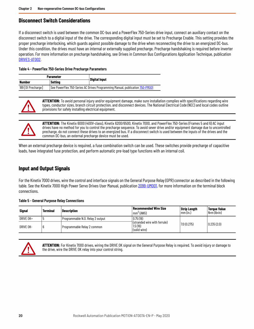
Disconnect Switch Considerations
If a disconnect switch is used between the common DC-bus and a PowerFlex 750-Series drive input, connect an auxiliary contact on the disconnect switch to a digital input of the drive. The corresponding digital input must be set to Precharge Enable. This setting provides the proper precharge interlocking, which guards against possible damage to the drive when reconnecting the drive to an energized DC-bus. Under this condition, the drives must have an internal or externally supplied precharge. Precharge handshaking is required before inverter operation. For more information on precharge handshaking, see Drives in Common Bus Configurations Application Technique, publication DRIVES-AT002.
When an external precharge device is required, a fuse combination switch can be used. These switches provide precharge of capacitive loads, have integrated fuse protection, and perform automatic pre-load type functions with an internal coil.
Input and Output Signals
For the Kinetix 7000 drives, wire the control and interface signals on the General Purpose Relay (GPR) connector as described in the following table. See the Kinetix 7000 High Power Servo Drives User Manual, publication 2099-UM001, for more information on the terminal block connections.
Table 4 - PowerFlex 750-Series Drive Precharge Parameters
ParameterDigital Input
Number Setting189 [DI Precharge] See PowerFlex 750-Series AC Drives Programming Manual, publication 750-PM001
ATTENTION: To avoid personal injury and/or equipment damage, make sure installation complies with specifications regarding wire types, conductor sizes, branch circuit protection, and disconnect devices. The National Electrical Code (NEC) and local codes outline provisions for safely installing electrical equipment.
ATTENTION: The Kinetix 6000 (400V-class), Kinetix 6200/6500, Kinetix 7000, and PowerFlex 750-Series (Frames 5 and 6) AC input drives have no method for you to control the precharge sequence. To avoid sever drive and/or equipment damage due to uncontrolled precharge, do not connect these drives to an energized bus. If a disconnect switch is used between the inputs of the drives and the common DC-bus, an external precharge device must be used.
Table 5 - General Purpose Relay Connections
Signal Terminal Description Recommended Wire Sizemm2 (AWG)
Strip Lengthmm (in.)
Torque ValueN•m (lb•in)
DRIVE OK+ 5 Programmable N.O. Relay 2 output 0.75 (18)(stranded wire with ferrule)1.5 (16)(solid wire)
7.0 (0.275) 0.235 (2.0)DRIVE OK- 6 Programmable Relay 2 common
ATTENTION: For Kinetix 7000 drives, wiring the DRIVE OK signal on the General Purpose Relay is required. To avoid injury or damage to the drive, wire the DRIVE OK relay into your control string.
20 Rockwell Automation Publication MOTION-AT007A-EN-P - May 2020

Non-regenerative Common DC-bus Configurations Chapter 2
Drive Ground Jumper Settings
Set the ground jumpers for the Kinetix 6000 (400V-class), Kinetix 6200/6500, and Kinetix 7000 drives according to the following tables. Refer to Additional Resources on page 81 for the user manual with instructions on how to set the ground jumpers/screws for your servo drive.
PowerFlex 750-Series drives contain protective metal-oxide varistors (MOV) and common mode capacitors referenced to ground. To guard against unstable operation and/or damage, the drive must be properly configured as shown in the following table.
For instructions on how to disconnect the PE jumpers, refer to PowerFlex 750-Series Power Jumpers Installation Instructions, publication 750-IN011.
Table 6 - Ground Jumper Settings for Kinetix 6000 (400V-class) and Kinetix 6200/6500 Drives
Ground ConfigurationGround Jumper Setting Based on Selected Power Supply
2198-Pxxx DC-bus Power Supply (1)
(1) 2198-Pxxx DC-bus power supply when 2198-DB20-F, 2198-DB42-F, 2198-DB80-F, or 2198-DB290-F AC line filter is used.
2198-Pxxx DC-bus Power Supply (2)
(2) 2198-Pxxx DC-bus power supply when 2198-DBR20-F, 2198-DBR40-F, 2198-DBR90-F, or 2198-DBR200-F AC line filter is used.
Grounded (wye) Grounded power (default setting)
Set for ungrounded power• AC-fed ungrounded• Corner grounded• Impedance grounded• DC-bus from active converter
Set for ungrounded power
Table 7 - Ground Jumper Settings for Kinetix 7000 Drives
Ground ConfigurationGround Jumper Setting Based on Selected Power Supply
2198-Pxxx DC-bus Power Supply (1)
(1) 2198-Pxxx DC-bus power supply when 2198-DB20-F, 2198-DB42-F, 2198-DB80-F, or 2198-DB290-F AC line filter is used.
2198-Pxxx DC-bus Power Supply (2)
(2) 2198-Pxxx DC-bus power supply when 2198-DBR20-F, 2198-DBR40-F, 2198-DBR90-F, or 2198-DBR200-F AC line filter is used.
Grounded (wye) Installed (default setting)
Removed• AC-fed ungrounded• Corner grounded• Impedance grounded• DC-bus from active converter
Removed
Table 8 - Power Jumper Settings for PowerFlex 750-Series Drives (Frames 1…6)
Ground ConfigurationGround Jumper Setting Based on Selected Power Supply
2198-Pxxx DC-bus Power Supply (1)
(1) 2198-Pxxx DC-bus power supply when 2198-DB20-F, 2198-DB42-F, 2198-DB80-F, or 2198-DB290-F AC line filter is used.
2198-Pxxx DC-bus Power Supply (2)
(2) 2198-Pxxx DC-bus power supply when 2198-DBR20-F, 2198-DBR40-F, 2198-DBR90-F, or 2198-DBR200-F AC line filter is used.
Grounded (wye) • Jumper PE-A connected (3) (4) (MOV/input filter caps)• Jumper PE-B connected (DC-bus common mode caps)
(3) When MOVs are disconnected, the power system must have its own transient protection to maintain known and controlled voltages.(4) Frame 5 and 6 common DC input drives do not have the PE-A jumper.
• Jumper PE-A disconnected (MOV/input filter caps)• Jumper PE-B disconnected (DC-bus common mode
caps)• AC-fed ungrounded• Corner grounded• Impedance grounded• DC-bus from active converter
• Jumper PE-A disconnected (MOV/input filter caps)• Jumper PE-B disconnected (DC-bus common mode caps)
Rockwell Automation Publication MOTION-AT007A-EN-P - May 2020 21

Chapter 2 Non-regenerative Common DC-bus Configurations
Kinetix 5700 Non-Regenerative Bus Supply Considerations
When extending the DC-bus from the power supply cluster, a capacitor module must be used to extend the bus. Refer to Kinetix 5700 Accessory Modules on page 71 for more information on when accessory modules are required.
The 2198-Pxxx DC-bus power supplies do not have a digital output, however, the CIPAxisState tag can be used either programmatically or with an external digital output to indicate that the drives can pull power from the bus. Refer to Integrated Motion on the EtherNet/IP Network Reference Manual, publication MOTION-RM003, and Knowledgebase Answer ID: QA35126, for more information on programming with Integrated Motion drives
Power Supply Ground Screw Setting
The 2198-Pxxx DC-bus power supply has a factory-installed ground screw for grounded-wye power distribution. The following table summarizes the ground screw/jumper settings for the 2198-Pxxx DC-bus power supply.
Table 9 - Ground Screw Settings for the DC-bus Power Supply
Ground Configuration 2198-Pxxx DC-bus Power Supply
Grounded (wye) Ground screw installed (default setting) (1)
(1) Ground screw is factory installed.
• Impedance grounded• Corner grounded• AC-fed ungrounded
Remove ground screw/jumper
IMPORTANT If you have grounded-wye power distribution in your facility, do not remove the ground screw from the DC-bus power supply. Remove the ground screw when using ungrounded, corner-grounded, or impedance-grounded power.
22 Rockwell Automation Publication MOTION-AT007A-EN-P - May 2020

Non-regenerative Common DC-bus Configurations Chapter 2
Contactor Enable Relay
The contactor-enable circuitry includes a relay-driven contact within the 2198-Pxxx DC-bus power supply. The relay protects the Kinetix 5700 drive system in the event of overloads or other fault conditions.
Figure 13 - Contactor-enable Control String
An AC three-phase mains contactor must be wired in series between the branch circuit protection and the power supply. In addition, the AC three-phase contactor control string must be wired in series with the contactor-enable relay at the contactor-enable terminals.
PowerFlex 750-Series drives are not required to include a contactor-enable control string and they do not have a dedicated contactor enable relay. Although not required, if leveraging Integrated Motion with a PowerFlex 755 drive, we recommend that you configure a digital output from the drive as Contactor Enable and include it in the contactor enable control string.
A Contactor Enable output can be configured in the PowerFlex 755 drive in integrated motion only. The operation of this output is tied to fault processing in the drive. The drive de-energizes the Contactor Enable output when an exception causes the axis to go to the Shutdown state.
Figure 14 - Contactor-enable Relay Circuit
Refer to Kinetix 5700 Servo Drives User Manual, publication 2198-UM002, for additional information on the contactor-enable circuitry.
This configuration is only valid when an auxiliary power supply is used for control power with frames 1…7 drives.
ATTENTION: Wiring the contactor enable relay is required for Kinetix 5700, Kinetix 6x00, and Kinetix 7000 drive systems to help prevent personal injury or damage to Kinetix drive modules. Wire the contactor enable relay into your control string so that:• three-phase power is removed and the power supply or regenerative bus supply is protected under various fault conditions• three-phase power is never applied to the Kinetix 5700 drive system before control power is applied.
ATTENTION: For Kinetix 6000 (400V-class) and Kinetix 6200/6500 drive in common-bus configurations, the contactor enable connections for leader and follower drives must be wired in series to the control string. A contactor or other device that routinely disconnects and reapplies the AC line to the bus supply can cause drive hardware damage. If an input device is used, operation must not exceed two cycles per minute (maximum) or damage can occur to the precharge circuit.
Kinetix 57002198-P208
DC-bus Power Supply
CONT
EN+
CONT
EN–
GPR2
+GP
R2–
Kinetix 6x002094-BCxx-Mxx-S
Integrated Axis Module
Kinetix 70002099-BMxx-SServo Drive
CONT
EN+
CONT
EN–
STOP *
START *
CR1 *
CR1 *CR1 *
M1 *24V AC/DC
50/60 Hz
* Indicates User Supplied Component
CONT EN-
CONT EN+Normally
OpenRelay
Power Supply
Rockwell Automation Publication MOTION-AT007A-EN-P - May 2020 23

Chapter 2 Non-regenerative Common DC-bus Configurations
System Sizing
These limitations apply to systems supplied by a single 2198-Pxxx or multiple 2198-P208 DC-bus power supplies:• The sum of the inverter motor-power cable lengths for all inverters on the same DC bus-sharing group must not exceed 1200 m
(3937 ft) to comply with IEC 61800-3 (category C3) requirements when used with 2198-DBRxx-F line filters. 2198-DBxx-F line filters have a total motor cable length limit of 400 m (1312 ft). See the Kinetix 5700 Servo Drives User Manual, publication 2198-UM002, for additional motor power cable-length limitations.
• The total system capacitance limit is based on the power supply catalog number. DC-bus groups must not exceed the limits as defined in Kinetix and PowerFlex Drive Specifications on page 59.
• No more than three 2198-P208 DC-bus power supplies can be used to increase the converter power.• If using the 24V DC shared-bus connection system, add another 24V power supply when control input power to a cluster of drive
modules exceeds 40 A.• The Kinetix 5700 system can have multiple drive clusters in a single DC-bus group. See the Kinetix 5700 Servo Drives User Manual,
publication 2198-UM002, for more information on extended clusters.
Refer to the Kinetix 5700 Servo Drives User Manual, publication 2198-UM002, for additional information on system sizing guidelines.
The motor required for a particular application determines the drive required for full motor performance. For best results, use Motion Analyzer system sizing and selection tool, available at https://motionanalyzer.rockwellautomation.com/.
Capacitance Sizing
Total system capacitance is the sum of all internal capacitance values from each of the drive modules (AC drives, single-axis inverters, dual-axis inverters, power supplies, and capacitor modules) in the same DC-bus group.
The total system capacitance must be less than the maximum supported DC-bus capacitance value of the power supply (refer to Kinetix and PowerFlex Drive Specifications on page 59).
All drives have a DC-bus capacitance that is proportional to their power ratings. When used in a common DC-bus configuration, these capacitors are directly connected in parallel. This connection results in the DC-bus ripple being shared proportional to the power rating of the drive. When the ratio of the capacitance to the drive-rated current is consistent, it provides the best DC-bus ripple sharing.
For 400/480V AC, the target ratio is 40 µF/A ±10% or greater. For all drives supported in this publication, the target ratio is met when a capacitor module is used to extend the DC-bus, proper DC-bus cable length guidelines are followed, and low-inductance DC cable is used. See DC-bus Connections on page 8 for more information.
Circuit Protection
Do not daisy chain drives to share DC-bus fusing. Configure the shared DC-bus in a star configuration to enable proper fusing. Use fast semiconductor fuses in the DC links to minimize destructive energy in the event of a part or control malfunction. Size fuses to handle large peak currents at the end of precharge.
• See Kinetix and PowerFlex Drive Specifications on page 59 for the recommended common DC-bus circuit protection devices.• See the Kinetix 5700 Servo Drives User Manual, publication 2198-UM002, for recommended AC input circuit protection for the Bulletin
2198 power supply.
IMPORTANT If your total system capacitance value exceeds the maximum supported capacitance value of the DC-bus power supply, perform one of the following:• Increase the size of the 2198-Pxxx DC-bus power supply• Use multiple 2198-P208 DC-bus power supplies (1…3 power supplies are possible with only 2198-P208 power supply)• Decrease the total system capacitance by removing inverters or capacitor modules from the DC-bus group• Separate clusters into multiple DC-bus groups
24 Rockwell Automation Publication MOTION-AT007A-EN-P - May 2020

Chapter 3
Non-regenerative Common DC-bus Configurations With Passive or Active Shunt
This system also uses a diode-front-end power supply that converts the three-phase AC line voltage into a non-filtered DC-bus voltage. However, in this configuration the drive uses the internal IGBT shunt resistor or an external passive or active shunt for power dissipation of excess regenerative energy. Rockwell Automation does not offer external active shunt products. Contact our Encompass™ Partners for these shunt resistor (braking chopper) products.
Supported Products
At the time of publication, the following Kinetix® 5700 non-regenerative DC-bus supplies and drives are supported.
Table 10 - Kinetix 5700 Non-regenerative Drive Modules
DC-bus Power SupplyCat. No. Supported Drives
• 2198-P031• 2198-P070• 2198-P141• 2198-P208
PowerFlex® 750-Series: Frames 1…6 (1)
(1) PowerFlex 750-Series (Frames 5 and 6) DC input version drives with precharge must be selected.
Kinetix 7000: 2099-BM06-S…2099-BM12-S
Kinetix 6000 and Kinetix 6200/6500: All 460V configurations (2)
(2) Kinetix 6000 configurations require firmware revision 1.92 or later.
Rockwell Automation Publication MOTION-AT007A-EN-P - May 2020 25

Chapter 3 Non-regenerative Common DC-bus Configurations With Passive or Active Shunt
Typical System Configurations
In this example, standalone AC drives, Kinetix 6000 drives, and Kinetix 7000 drives receive DC-bus power from three 2198-P208 DC-bus power supplies. An external passive shunt is wired to one of the 2198-P208 DC-bus supplies.
Figure 15 - DC-bus Supply with Multiple AC Drives and External Passive Shunt
(1) Line reactors are required when three 2198-P208 DC-bus supplies are configured. For line reactor requirements and selection when one or two 2198-P208 DC-bus supplies are configured, see the Kinetix 5700 Servo Drives User Manual, publication 2198-UM002.
(2) For passive shunt wiring and mounting information, see the Kinetix 5700 Servo Drives User Manual, publication 2198-UM002.
Table 11 - Special Bus Requirements
Drawing Designation Supported Drives Special Bus Requirements
AC drivesPowerFlex 750-Series: Frames 1…6
NoneKinetix 7000: 2099-BM06-S…2099-BM08-SKinetix 7000: 2099-BM09-S…2099-BM12-S
Kinetix 6000 andKinetix 6200/6500 drives
Kinetix 6000: All 460V configurations (1)
(1) No internal precharge. Drives must be placed in common-bus follower configuration.
NoneKinetix 6200/6500: All 460V configurations (1)
2198
-P20
8
2198
-CAP
MOD-
2240
2198
-CAP
MOD-
DCBU
S-IO
2198
-P20
8
2198
-P20
8
DC+ DC-
M
DC+ DC-
M
AC Drive AC Drive
M M M
DC+ DC-
Capacitor Module
DC-BusPower Supply
Extension Module
DC Bus
DC-BusPower Supply
DC-BusPower Supply
ReactorLine
ReactorLine
ReactorLine
AC Line FilterThree-phase
CircuitProtection
CircuitProtection
CircuitProtection
Kinetix 6000 orKinetix 6200/6500 Drives
M
Integrated Axis Module
Axis Modules
Three-phaseSource Contactor
Three-phaseCircuitProtection
(1)
(2) External Bulletin 2198 Passive Shunt
(1)
(1)
26 Rockwell Automation Publication MOTION-AT007A-EN-P - May 2020

Non-regenerative Common DC-bus Configurations With Passive or Active Shunt Chapter 3
Figure 16 - DC-bus Supply with Multiple AC Drives and External Active Shunt
(1) Line reactors are required when three 2198-P208 DC-bus supplies are configured. For line reactor requirements and selection when one or two 2198-P208 DC-bus supplies are configured, see the Kinetix 5700 Servo Drives User Manual, publication 2198-UM002.
(2) A DC-bus conditioner module is required to limit DC-bus voltage overshoot at power-on.(3) Locate the external active shunt close to the DC-bus conditioner. For active shunt wiring and mounting information, see the Kinetix 5700 Servo Drives User Manual, publication 2198-UM002.
Table 12 - Special Bus Requirements
Drawing Designation Supported Drives Special Bus Requirements
AC drivesPowerFlex 750-Series: Frames 1…6
NoneKinetix 7000: 2099-BM06-S…2099-BM08-S
Kinetix 7000: 2099-BM09-S…2099-BM12-S (1)
(1) External precharge must be provided if a disconnect between the DC-bus and the drive DC input is used.
Kinetix 6000 and Kinetix 6200/6500 drives
Kinetix 6000: All 460V configurations (2)
(2) No internal precharge. Drives must be placed in common-bus follower configuration.
NoneKinetix 6200/6500: All 460V configurations (2)
2198
-P20
8
2198
-CAP
MOD-
2240
2198
-P20
8
2198
-P20
8
DC+ DC-
M
AC Drive
M M M
DC+ DC-
Capacitor Module
DC-BusPower Supply
DC Bus
DC-BusPower Supply
DC-BusPower Supply
ReactorLine
ReactorLine
ReactorLine
CircuitProtection
CircuitProtection
CircuitProtection
External ActiveShunt
BR
BR1 BR2
DC+ DC-
2198
-DCB
USCO
ND-R
P312
DC-bus Conditioner
Kinetix 6000 orKinetix 6200/6500 Drives
M
Integrated Axis Module
Axis Modules
AC Line FilterThree-phase
Three-phaseSource Contactor
Three-phaseCircuitProtection
(3)
(2)
(1)
(1)
(1)
Rockwell Automation Publication MOTION-AT007A-EN-P - May 2020 27

Chapter 3 Non-regenerative Common DC-bus Configurations With Passive or Active Shunt
General Considerations
This section includes information on AC line impedance, disconnect switch connections, and ground screw/jumper settings, depending on the drive family.
• All system components (bus supply and PowerFlex or Kinetix drives) must be selected for the same AC-line voltage. • Low-inductance type DC-bus must be used. See DC-bus Connections on page 8 for details.• To be used in a common-bus system with a Kinetix 5700 bus supply, the Kinetix 6000 or Kinetix 6200/6500 drive systems must be
configured as common-bus follower (internal IGBT for shunting is disabled).
• The Kinetix 7000 drive internal IGBT for shunting is not used by the drive main control for bus regulation. Therefore, any type of regulation must come from an external source.
• Refer to Additional Resources on page 81 for user documentation with the maximum motor cable length requirements of the drives specific to your application.
AC Line Impedance Considerations
In the following use cases, an additional transformer or line reactor is required due to faults or potential damage associated with AC line disturbances:
• Installation site has switched power-factor correction capacitors.• Installation site has lightning strikes or voltage spikes in excess of 6000V peak.• Installation site has power interruptions or voltage dips in excess of 200V AC.• The transformer kVA is more than 10 times larger than the drive kVA or the percent source impedance relative to each converter is
less than 0.5%.
In the following use cases, a line reactor is required due to faults associated with sharing AC line-input on multiple converters:• Repetitive AC input line-voltage notching is present. For example, if silicon-controlled rectifier drive is connected to the same AC
input power source.• Powering 2198-Pxxx DC-bus power supply and 2198-RPxxx regenerative bus supply from the same AC input-power source.
- Line reactor in the AC input-power string is not required for the DC-bus power supply in this use case, but is recommended for the prevention of issues caused by other use cases.
• Powering two or three 2198-P208 DC-bus power supplies from the same AC input-power source that share the same DC-bus.- In this use case, a line reactor is required for each 2198-P208 DC-bus power supply to make sure that they share current more
evenly.
Refer to Kinetix 5700 Servo Drives User Manual, publication 2198-UM002, for additional AC line impedance considerations.
ATTENTION: The incorrect use or configuration of third party assemblies can result in reduced system reliability and drive damage.
IMPORTANT Do not include the 2094-BSP2 shunt module on the 2094 power rail.
28 Rockwell Automation Publication MOTION-AT007A-EN-P - May 2020

Non-regenerative Common DC-bus Configurations With Passive or Active Shunt Chapter 3
Disconnect Switch Considerations
If a disconnect switch is used between the common DC-bus and a PowerFlex 750-Series drive input, connect an auxiliary contact on the disconnect switch to a digital input of the drive. The corresponding digital input must be set to Precharge Enable. This setting provides the proper precharge interlocking, which guards against possible damage to the drive when reconnecting the drive to an energized DC-bus. Under this condition, the drives must have an internal or externally supplied precharge. Precharge handshaking is required before inverter operation.
When an external precharge device is required, a fuse combination switch can be used. These switches provide precharge of capacitive loads, have integrated fuse protection, and perform automatic pre-load type functions with an internal coil.
Input and Output Signals
For the Kinetix 7000 drives, wire the control and interface signals on the General Purpose Relay (GPR) connector as described in the following table. See the Kinetix 7000 High Power Servo Drives User Manual, publication 2099-UM001, for more information on the terminal block connections.
Table 13 - PowerFlex 750-Series Drive Precharge Parameter
ParameterDigital Input
Number Setting189 [DI Precharge] See PowerFlex 750-Series AC Drives Programming Manual, publication 750-PM001
ATTENTION: To avoid personal injury and/or equipment damage, make sure installation complies with specifications regarding wire types, conductor sizes, branch circuit protection, and disconnect devices. The National Electrical Code (NEC) and local codes outline provisions for safely installing electrical equipment.
ATTENTION: The Kinetix 6000 (400V-class), Kinetix 6200/6500, Kinetix 7000, and PowerFlex 750-Series (Frames 5 and 6) AC input drives have no method for you to control the precharge sequence. To avoid sever drive and/or equipment damage due to uncontrolled precharge, do not connect these drives to an energized bus. If a disconnect switch is used between the inputs of the drives and the common DC-bus, an external precharge device must be used.
Table 14 - General Purpose Relay Connections
Signal Terminal Description Recommended Wire Sizemm2 (AWG)
Strip Lengthmm (in.)
Torque ValueN•m (lb•in)
DRIVE OK+ 5 Programmable N.O. Relay 2 output 0.75 (18)(stranded wire with ferrule)1.5 (16)(solid wire)
7.0 (0.275) 0.235 (2.0)DRIVE OK- 6 Programmable Relay 2 common
ATTENTION: For the Kinetix 7000 drives, wiring the DRIVE OK signal on the General Purpose Relay is required. To avoid injury or damage to the drive, wire the DRIVE OK relay into your control string.
Rockwell Automation Publication MOTION-AT007A-EN-P - May 2020 29

Chapter 3 Non-regenerative Common DC-bus Configurations With Passive or Active Shunt
Drive Ground Jumper Settings
Set the ground jumpers for the Kinetix 6000 (400V-class), Kinetix 6200/6500, and Kinetix 7000 drives according to the following tables. Refer to Additional Resources on page 81 for the user manual with instructions on how to set the ground jumpers/screws for your servo drive.
PowerFlex 750-Series drives contain protective metal-oxide varistors (MOV) and common mode capacitors referenced to ground. To guard against unstable operation and/or damage, the drive must be properly configured as shown in the following table.
For instructions on how to disconnect the PE jumpers, refer to PowerFlex 750-Series Power Jumpers Installation Instructions, publication 750-IN011.
Table 15 - Ground Jumper Settings for Kinetix 6000 (400V-class) and Kinetix 6200/6500 Drives
Ground ConfigurationGround Jumper Setting Based on Selected Power Supply
2198-Pxxx DC-bus Power Supply (1)
(1) 2198-Pxxx DC-bus power supply when 2198-DB20-F, 2198-DB42-F, 2198-DB80-F, or 2198-DB290-F AC line filter is used.
2198-Pxxx DC-bus Power Supply (2)
(2) 2198-Pxxx DC-bus power supply when 2198-DBR20-F, 2198-DBR40-F, 2198-DBR90-F, or 2198-DBR200-F AC line filter is used.
Grounded (wye) Grounded power (default setting)
Set for ungrounded power• AC-fed ungrounded• Corner grounded• Impedance grounded• DC-bus from active converter
Set for ungrounded power
Table 16 - Ground Jumper Settings for Kinetix 7000 Drives
Ground ConfigurationGround Jumper Setting Based on Selected Power Supply
2198-Pxxx DC-bus Power Supply (1)
(1) 2198-Pxxx DC-bus power supply when 2198-DB20-F, 2198-DB42-F, 2198-DB80-F, or 2198-DB290-F AC line filter is used.
2198-Pxxx DC-bus Power Supply (2)
(2) 2198-Pxxx DC-bus power supply when 2198-DBR20-F, 2198-DBR40-F, 2198-DBR90-F, or 2198-DBR200-F AC line filter is used.
Grounded (wye) Installed (default setting)
Removed• AC-fed ungrounded• Corner grounded• Impedance grounded• DC-bus from active converter
Removed
Table 17 - Power Jumper Settings for PowerFlex 750-Series Drives (Frames 1…6)
Ground ConfigurationGround Jumper Setting Based on Selected Power Supply
2198-Pxxx DC-bus Power Supply (1)
(1) 2198-Pxxx DC-bus power supply when 2198-DB20-F, 2198-DB42-F, 2198-DB80-F, or 2198-DB290-F AC line filter is used.
2198-Pxxx DC-bus Power Supply (2)
(2) 2198-Pxxx DC-bus power supply when 2198-DBR20-F, 2198-DBR40-F, 2198-DBR90-F, or 2198-DBR200-F AC line filter is used.
Grounded (wye) • Jumper PE-A connected (3) (4) (MOV/input filter caps)• Jumper PE-B connected (DC-bus common mode caps)
(3) When MOVs are disconnected, the power system must have its own transient protection to maintain known and controlled voltages.(4) Frames 5 and 6 common DC input drives do not have the PE-A jumper.
• Jumper PE-A disconnected (MOV/input filter caps)• Jumper PE-B disconnected (DC-bus common mode caps)
• AC-fed ungrounded• Corner grounded• Impedance grounded• DC-bus from active converter
• Jumper PE-A disconnected (MOV/input filter caps)• Jumper PE-B disconnected (DC-bus common mode caps)
30 Rockwell Automation Publication MOTION-AT007A-EN-P - May 2020

Non-regenerative Common DC-bus Configurations With Passive or Active Shunt Chapter 3
Active Shunt Considerations
External active shunts are required in the following use cases:• One permanent magnet motor runs above its bus overvoltage speed. See Kinetix 5700 Servo Drives User Manual, publication
2198-UM002, information on the Field Weakening Mode feature.• One permanent magnet motor drives a vertical load that could make the motor accelerate above the bus overvoltage speed during a
fault condition.
Active shunts are available from the Rockwell Automation Encompass partner Powerohm Resistors, Inc. See http://www.powerohm.com for more information on Powerohm active shunts.
ATTENTION: To avoid damage to the Kinetix 5700 drive system, wire the active shunt thermal switch to a digital input on the power supply and configure the Shunt Thermal Switch OK function in the Logix Designer application.
ATTENTION: DC-bus failure can cause damage to all drive modules in the bus group, not just the inverter connected to the motor.
IMPORTANT Powerohm Bulletin PKBxxx active shunt modules use built-in internal brake resistors. Bulletin PWBxxx active shunt modules require appropriately sized external brake resistors.
Table 18 - Compatible Active Shunt Specifications (internal brake resistor)
Kinetix 5700 Power SupplyPowerohm ResistorsCat. No. (1)
(1) How the Powerohm PKBxxx shunts connect to the 2198-Pxxx regenerative bus supply is explained in 2198-Pxxx Power Supply with External Active Shunt (built-in brake resistor) on page 33.
Input Voltage,nom
Turn -onBus Voltage
Continuous PowerkW
Resistance(internal)Ω
Resistance(minimum)Ω
Continuous CurrentAmps
Peak CurrentAmps
2198-Pxxx DC-bus power supplyPKB005
480V AC 750V DC1.50 108 – 2.00 6.9
PKB010 2.06 52.7 – 2.75 14.2PKB050 7.00 10.5 – 9.30 71.4
Table 19 - Compatible Active Shunt Specifications (no internal brake resistor)
Kinetix 5700 Power SupplyPowerohm ResistorsCat. No. (1)
(1) How the Powerohm PWBxxx shunts connect to the 2198-Pxxx regenerative bus supply is explained in 2198-Pxxx Power Supply with External Active Shunt (external brake resistor) on page 34.
Input Voltage,nom
Turn -onBus Voltage
Continuous PowerkW
Resistance(internal)Ω
Resistance(minimum)Ω
Continuous CurrentAmps
Peak CurrentAmps
2198-Pxxx DC-bus power supplyPWB035
480V AC 750V DC26.25 – 7.5 35 100
PWB110 82.5 – 2.5 110 300
ATTENTION: Do not use Powerohm active-shunt modules at input line voltages that exceed 528V AC. Active-shunt thermal-overload shutdown can occur if input line voltage exceeds 528V AC.
Rockwell Automation Publication MOTION-AT007A-EN-P - May 2020 31

Chapter 3 Non-regenerative Common DC-bus Configurations With Passive or Active Shunt
Kinetix 5700 Non-Regenerative Bus Supply Considerations
When extending the DC-bus from the power supply cluster, a capacitor module must be used to extend the bus. Refer to Kinetix 5700 Accessory Modules on page 71 for more information on when accessory modules are required.
The 2198-Pxxx DC-bus power supplies do not have a digital output, however, the CIPAxisState tag can be used either programmatically or with an external digital output to indicate that the drives can pull power from the bus. Refer to Integrated Motion on the EtherNet/IP Network Reference Manual, publication MOTION-RM003, and Knowledgebase Answer ID: QA35126, for more information on programming with Integrated Motion drives
Shunt Connections
The 2198-Pxxx DC-bus power supplies all include an internal shunt that is wired to the shunt resistor (RC) connector at the factory. Bulletin 2198-Rxxx external passive shunts are available to provide additional shunt capacity for applications where the internal shunt capacity is exceeded.
Connect an external passive shunt to only the DC-bus power supply. You must disconnect the internal shunt wires at the RC connector before connecting external passive-shunt resistor wires.
Catalog numbers 2198-R014, 2198-R031, and 2198-R127 are composed of resistor coils that are housed inside an enclosure. Catalog number 2198-R004 is a shunt resistor without an enclosure.
Figure 17 - External Passive Shunts
Refer to the Kinetix 5700 Servo Drives User Manual, publication 2198-UM002, for passive shunt wiring and mounting considerations.
Table 20 - DC-bus Power Supply Passive-shunt Options
DC-bus Power SupplyCat. No.
Internal Shunt Specifications External Shunt Module Compatibility (1)
Cat. No.
(1) Shunt resistor selection is based on the needs of your actual hardware configuration.
Ω W 2198-R127 2198-R031 2198-R014 2198-R0042198-P031
37.5 75– – X X
2198-P070 – – X X2198-P141
13.5 200X X X X
2198-P208 X X X X
Table 21 - External Shunt Module Specifications
Shunt ModuleCat. No.
ResistanceW
Continuous PowerW
Weight, approxkg (lb)
2198-R004 33 400 1.8 (4.0)2198-R014 9.4 1400 9.1 (20)2198-R031 33 3100 16.8 (37)
2198-R127 (1)
(1) This product presents a lift hazard. To avoid personal injury, use care when lifting the product.
13 12,700 22.2 (49)
2198-R014, 2198-R031,and 2198-R127
Shunt Modules2198-R004Shunt Resistor
32 Rockwell Automation Publication MOTION-AT007A-EN-P - May 2020

Non-regenerative Common DC-bus Configurations With Passive or Active Shunt Chapter 3
For drive systems that include the 2198-Pxxx DC-bus power supply and Powerohm PKBxxx or PWBxxx active shunts, make the active shunt connections at the external DC-bus studs on accessory modules.
Accessory modules are equipped with spacers that slide onto M8 studs. When the system configuration includes external DC-bus and active shunt connections, external DC-bus connections are made below the spacer and active shunt connections are made above the spacer.
Figure 18 - Active Shunt Connections
(1) An external active shunt can be wired to any of the accessory modules. See Kinetix 5700 Servo Drives User Manual, publication 2198-UM002, for more information on mounting and accessory module example configurations. The 2198-CAPMOD-2240 capacitor module is preferred because it provides additional system capacitance.
(2) Position flexible bus-bars (when two accessory modules are used) below the DC-bus lug connections. The flexible bus-bars are used to parallel the extended DC-bus with another accessory module in 208 A systems (not required when only one accessory module is used in 104 A systems). Flexible bus-bars are included with 2198-CAPMOD-DCBUS-IO extension modules or you can order 2198-KITCON-CAPMOD2240 or 2198-KITCON-DCBUSCOND replacement kits.
For compatible Powerohm active shunts paired with 2198-Pxxx DC-bus power supplies, refer to Kinetix 5700 Servo Drives User Manual, publication 2198-UM002.
Figure 19 - 2198-Pxxx Power Supply with External Active Shunt (built-in brake resistor)
(1) Configure any available digital input as Shunt Thermal Switch OK.(2) Powerohm PKB050 and PKB050-800 shunts require 120V AC between pins 9 and 10 to supply power to the cooling fans.
For more information on wiring to these Powerohm Bulletin PKBxxx active shunts, see the Knowledgebase Answer ID: 1082776.
ATTENTION: To avoid damage to the Kinetix 5700 drive system, wire the active shunt thermal switch to a digital input on the power supply and configure the Shunt Thermal Switch OK function in the Studio 5000 Logix Designer® application.
2198-DCBUSCOND-RP312 2198-CAPMOD-2240 or 2198-CAPMOD-DCBUS-IO (1)Accessory Modules(2198-CAPMOD-2240 capacitor module is shown)
Active ShuntLug Connections
(above spacer)
DC-busLug Connections andFlexible Bus-bars (2)
(below spacer)
Spacer
DC+DC–
120V AC910
34
DC+
DC–
INxCOM 24V DC
(1)(2)
2198-Pxxx DC-Bus Power Supply
PowerohmBulletin PKBxxx-xxx Active Shunt Module
Fault Contact
Digital Input(IOD) Connector
External DC-bus Resistor
4.6 m (15 ft) Maximum Cable Length2198-xxxx-ERSx
Inverter2198-CAPMOD-2240Capacitor Module
Rockwell Automation Publication MOTION-AT007A-EN-P - May 2020 33

Chapter 3 Non-regenerative Common DC-bus Configurations With Passive or Active Shunt
Figure 20 - 2198-Pxxx Power Supply with External Active Shunt (external brake resistor)
(1) Configure any available digital input as Shunt Thermal Switch OK. See the Kinetix 5700 Servo Drives User Manual, publication 2198-UM002, for more information on configuring digital inputs.(2) Powerohm PWB050 and PWB050-800 shunts require 120V AC between pins 9 and 10 to supply power to the cooling fans.
See Knowledgebase document 1082777 for more information on wiring to these Powerohm Bulletin PWBxxx active shunts.
Refer to the Powerohm documentation included with your Bulletin PKB or PWB shunt module to install, wire, and configure the module.• To avoid nuisance thermal overload trips, configure Bulletin PKB and PWB active-shunt modules to the highest shunt turn-on voltage
setting. The recommended setting for Line Voltage Level Jumper is JP5.• Configure Bulletin PKB and PWB active-shunt modules in Internal (automatic) mode. Unless an external enable signal is provided,
configure the Brake Enable Jumper in Internal (automatic) mode (JP6 is in the downward position).
Power Supply Ground Screw Setting
The 2198-Pxxx DC-bus power supply has a factory-installed ground screw for grounded-wye power distribution. This table summarizes the ground screw settings for the 2198-Pxxx DC-bus power supply.
Table 22 - Ground Screw Settings for the DC-bus Power Supply
Ground Configuration 2198-Pxxx DC-bus Power Supply
Grounded (wye) Ground screw installed (default setting) (1)
(1) Ground screw is factory installed.
• Impedance grounded• Corner grounded• AC-fed ungrounded
Remove ground screw/jumper
IMPORTANT If you have grounded-wye power distribution in your facility, do not remove the ground screw from the DC-bus power supply. Remove the ground screw when using ungrounded, corner-grounded, or impedance-grounded power.
34
R1R2
DC+
DC–
DC+
DC–
DC+
DC–
INxCOM (1) 24V DC
120V AC910
(2)
TSTS
External DC-bus
Powerohm External Passive
Shunt Module
Resistor
Thermal SwitchDigital Input
(IOD) Connector
Powerohm Bulletin PWBxxx-xxxActive Shunt Module
4.6 m (15 ft) Maximum Cable Length
9.1 m (30 ft) Maximum Cable Length
2198-xxxx-ERSxInverter
Fault Contact
2198-Pxxx DC-Bus
Power Supply
2198-CAPMOD-2240Capacitor Module
34 Rockwell Automation Publication MOTION-AT007A-EN-P - May 2020

Non-regenerative Common DC-bus Configurations With Passive or Active Shunt Chapter 3
Contactor Enable Relay
The contactor-enable circuitry includes a relay-driven contact within the 2198-Pxxx DC-bus power supply. The relay protects the Kinetix 5700 drive system in the event of overloads or other fault conditions.
Figure 21 - Contactor-enable Control String
An AC three-phase mains contactor must be wired in series between the branch circuit protection and the power supply. In addition, the AC three-phase contactor control string must be wired in series with the contactor-enable relay at the contactor-enable terminals.
PowerFlex 750-Series drives are not required to include a contactor-enable control string and they do not have a dedicated contactor enable relay. Although not required, if leveraging Integrated Motion with a PowerFlex 755 drive, we recommend that you configure a digital output from the drive as Contactor Enable and include it in the contactor enable control string.
A Contactor Enable output can be configured in the PowerFlex 755 drive in integrated motion only. The operation of this output is tied to fault processing in the drive. The drive de-energizes the Contactor Enable output when an exception causes the axis to go to the Shutdown state.
Figure 22 - Contactor-enable Relay Circuit
Refer to Kinetix 5700 Servo Drives User Manual, publication 2198-UM002, for additional information on the contactor-enable circuitry.
This configuration is only valid when an auxiliary power supply is used for control power with frames 1…7 drives.
ATTENTION: Wiring the contactor enable relay is required for Kinetix 5700, Kinetix 6x00, and Kinetix 7000 drive systems to help prevent personal injury or damage to Kinetix drive modules. Wire the contactor enable relay into your control string so that:• three-phase power is removed and the power supply or regenerative bus supply is protected under various fault conditions• three-phase power is never applied to the Kinetix 5700 drive system before control power is applied.
ATTENTION: For Kinetix 6000 (400V-class) and Kinetix 6200/6500 drive in common-bus configurations, the contactor enable connections for leader and follower drives must be wired in series to the control string. A contactor or other device that routinely disconnects and reapplies the AC line to the bus supply can cause drive hardware damage. If an input device is used, operation must not exceed two cycles per minute (maximum) or damage can occur to the precharge circuit.
Kinetix 57002198-P208
DC-bus Power Supply
CONT
EN+
CONT
EN–
GPR2
+GP
R2–
Kinetix 6x002094-BCxx-Mxx-S
Integrated Axis Module
Kinetix 70002099-BMxx-SServo Drive
CONT
EN+
CONT
EN–
STOP *
START *
CR1 *
CR1 *CR1 *
M1 *24V AC/DC
50/60 Hz
* Indicates User Supplied Component
CONT EN-
CONT EN+Normally
OpenRelay
Power Supply
Rockwell Automation Publication MOTION-AT007A-EN-P - May 2020 35

Chapter 3 Non-regenerative Common DC-bus Configurations With Passive or Active Shunt
System Sizing
These limitations apply to systems supplied by a single 2198-Pxxx or multiple 2198-P208 DC-bus power supplies:• The sum of the inverter motor-power cable lengths for all inverters on the same DC bus-sharing group must not exceed 1200 m
(3937 ft) to comply with IEC 61800-3 (category C3) requirements when used with 2198-DBRxx-F line filters. 2198-DBxx-F line filters have a total motor cable length limit of 400 m (1312 ft). See the Kinetix 5700 Servo Drives User Manual, publication 2198-UM002, for additional motor power cable-length limitations.
• The total system capacitance limit is based on the power supply catalog number. DC-bus groups must not exceed the limits as defined in Kinetix and PowerFlex Drive Specifications on page 59.
• No more than three 2198-P208 DC-bus power supplies can be used to increase the converter power.• If using the 24V DC shared-bus connection system, add another 24V power supply when control input power to a cluster of drive
modules exceeds 40 A.• The Kinetix 5700 system can have multiple drive clusters in a single DC-bus group. See the Kinetix 5700 Servo Drives User Manual,
publication 2198-UM002, for more information on extended clusters.
Refer to the Kinetix 5700 Servo Drives User Manual, publication 2198-UM002, for additional information on system sizing guidelines.
The motor required for a particular application determines the drive required for full motor performance. For best results, use Motion Analyzer system sizing and selection tool, available at https://motionanalyzer.rockwellautomation.com/.
Capacitance Sizing
Total system capacitance is the sum of all internal capacitance values from each of the drive modules (AC drives, single-axis inverters, dual-axis inverters, power supplies, and capacitor modules) in the same DC-bus group.
The total system capacitance must be less than the maximum supported DC-bus capacitance value of the power supply (refer to Kinetix and PowerFlex Drive Specifications on page 59).
All drives have a DC-bus capacitance that is proportional to their power ratings. When used in a common DC-bus configuration, these capacitors are directly connected in parallel. This connection results in the DC-bus ripple being shared proportional to the power rating of the drive. When the ratio of the capacitance to the drive-rated current is consistent, it provides the best DC-bus ripple sharing.
For 400/480V AC, the target ratio is 40 µF/A ±10% or greater. For all drives supported in this publication, the target ratio is met when a capacitor module is used to extend the DC-bus, proper DC-bus cable length guidelines are followed, and low-inductance DC cable is used. See DC-bus Connections on page 8 for more information.
Circuit Protection
Do not daisy chain drives to share DC-bus fusing. Configure the shared DC-bus in a star configuration to enable proper fusing. Use fast semiconductor fuses in the DC links to minimize destructive energy in the event of a part or control malfunction. Size fuses to handle large peak currents at the end of precharge.
• See Kinetix and PowerFlex Drive Specifications on page 59 for the recommended common DC-bus circuit protection devices.• See the Kinetix 5700 Servo Drives User Manual, publication 2198-UM002, for recommended AC input circuit protection for the Bulletin
2198 power supply.
IMPORTANT If your total system capacitance value exceeds the maximum supported capacitance value of the DC-bus power supply, perform one of the following:• Increase the size of the 2198-Pxxx DC-bus power supply• Use multiple 2198-P208 DC-bus power supplies (1…3 power supplies are possible with only 2198-P208 power supply)• Decrease the total system capacitance by removing inverters or capacitor modules from the DC-bus group• Separate clusters into multiple DC-bus groups
36 Rockwell Automation Publication MOTION-AT007A-EN-P - May 2020

Chapter 4
Regenerative Bus Supply Configurations
Regenerative bus supplies use a PWM-controlled IGBT converter for full regeneration of power to the AC line. The regenerative bus supply returns energy back to the distribution system instead of dissipating energy with shunt resistor (braking) technology. This configuration provides low AC-line harmonics and can be used to meet IEEE-519.
Supported Products
At the time of publication, the following products are supported.
Table 23 - Kinetix 5700 Regenerative Bus Supply Modules
Regenerative Bus SupplyCat. No. Supported Drives
• 2198-RP088• 2198-RP200• 2198-RP263• 2198-RP312
PowerFlex® 750-Series: Frames 1…6 (1)
(1) PowerFlex 750-Series (Frames 5 and 6) DC input version drives with precharge must be selected.
Kinetix® 7000: 2099-BM06-S…2099-BM12-S
Kinetix 6000 and Kinetix 6200/6500: All 460V configurations (2)
(2) Kinetix 6000 configurations require firmware revision 1.92 or later.
IMPORTANT The internal IGBT in Kinetix 6000 (460V) drives and Kinetix 6200/6500 drives are disabled in Common Bus Follower mode.
Rockwell Automation Publication MOTION-AT007A-EN-P - May 2020 37

Chapter 4 Regenerative Bus Supply Configurations
Typical System Configuration
In this example, standalone AC drives, Kinetix 6x00 drives, and Kinetix 7000 drives receive DC-bus power from the 2198-RP200 regenerative bus supply.
Figure 23 - Regenerative Bus Supply with Standalone AC Drives, Kinetix 6x00 Drives, and Kinetix 7000 Drives
(1) A line reactor can be required. For line reactor selection, see the Kinetix 5700 Servo Drives User Manual, publication 2198-UM002.(2) Kinetix 5700 regenerative bus supplies require an isolation transformer when connected to corner-grounded or ungrounded facility power.(3) Kinetix 5700 regenerative bus supplies in mixed common-bus systems require a DC-bus conditioner module in the power supply cluster.
General Considerations
This section includes information on AC line impedance, disconnect switch connections, and ground screw/jumper settings, depending on the drive family.
• All system components (bus supply and PowerFlex or Kinetix drives) must be selected for the same AC-line voltage. • Low-inductance type DC-bus must be used. See DC-bus Connections on page 8 for details.• To be used in a common-bus system with a Kinetix 5700 bus supply, the Kinetix 6000 or Kinetix 6200/6500 drive systems must be
configured as common-bus follower (internal IGBT for shunting is disabled).
• The Kinetix 7000 drive internal IGBT for shunting is not used by the drive main control for bus regulation, therefore any type of regulation must come from an external source.
• Refer to Additional Resources on page 81 for user documentation with the maximum motor cable length requirements of the drives specific to your application.
Table 24 - Special Bus Requirements
Drawing Designation Supported Drives Special Bus Requirements
AC drivesPowerFlex 750-Series: Frames 1…6
NoneKinetix 7000: 2099-BM06-S…2099-BM08-SKinetix 7000: 2099-BM09-S…2099-BM12-S
Kinetix 6000 and Kinetix 6200/6500 drives
Kinetix 6000: All 460V configurations (1)
(1) No internal precharge. Drives must be placed in common-bus follower configuration.
NoneKinetix 6200/6500: All 460V configurations (1)
ATTENTION: The incorrect use or configuration of third party assemblies can result in reduced system reliability and drive damage.
IMPORTANT Do not include the 2094-BSP2 shunt module on the 2094 power rail.
2198
-RP2
00(po
wer s
upply
clus
ter)
RegenerativeBus Supply
2198
-CAP
MOD-
2240
2198
-DCB
USCO
ND-R
P312
DC+ DC-
M
DC+ DC-
M
AC Drive AC Drive
M M M
DC+ DC-
Capacitor Module
DC-bus ConditionerModule
DC Bus
Kinetix 6000 orKinetix 6200/6500 Drives
M
Integrated Axis Module
Axis Modules
Three-phaseSource Reactor
LineContactor
Three-phase
(1)(2)(3)
38 Rockwell Automation Publication MOTION-AT007A-EN-P - May 2020

Regenerative Bus Supply Configurations Chapter 4
AC Line Impedance Considerations
In the following use cases, an additional transformer or line reactor is required due to faults or potential damage associated with AC line disturbances:
• Installation site has switched power-factor correction capacitors.• Installation site has lightning strikes or voltage spikes in excess of 6000V peak.• Installation site has power interruptions or voltage dips in excess of 200V AC.• The transformer kVA is more than 10 times larger than the drive kVA or the percent source impedance relative to each converter is
less than 0.5%.
In the following use cases, a line reactor is required due to faults associated with sharing AC line-input on multiple converters:• Repetitive AC input line-voltage notching is present. For example, if silicon-controlled rectifier drive is connected to the same AC
input power source.- In drive systems that include the regenerative bus supply, repetitive AC line voltage notching can cause the integrated AC line filter
to overheat and result in FLT S18 converter overtemperature faults.• Powering multiple (two or more) regenerative bus supplies from the same AC input-power source.
- Switching ripple from each regenerative bus supply can interfere with other regenerative bus supplies on the same AC input power source.
• Powering 2198-Pxxx DC-bus power supply and 2198-RPxxx regenerative bus supply from the same AC input-power source.- Switching ripple from the regenerative bus supply can impact the temperature of DC-bus capacitors in the DC-bus power supply. In
this use case, a line reactor is required in the AC input-power string leading to the regenerative bus supply.
Refer to Kinetix 5700 Servo Drives User Manual, publication 2198-UM002, for additional AC line impedance considerations.
Disconnect Switch Considerations
If a disconnect switch is used between the common DC-bus and a PowerFlex 750-Series drive input, connect an auxiliary contact on the disconnect switch to a digital input of the drive. The corresponding digital input must be set to Precharge Enable. This setting provides the proper precharge interlocking, which guards against possible damage to the drive when reconnecting the drive to an energized DC-bus. Under this condition, the drives must have an internal or externally supplied precharge. Precharge handshaking is required before inverter operation.
When an external precharge device is required, a fuse combination switch can be used. These switches provide precharge of capacitive loads, have integrated fuse protection, and perform automatic pre-load type functions with an internal coil.
Table 25 - PowerFlex 750-Series Drive Precharge Parameter
ParameterDigital Input
Number Setting189 [DI Precharge] See PowerFlex 750-Series AC Drives Programming Manual, publication 750-PM001.
ATTENTION: To avoid personal injury and/or equipment damage, make sure installation complies with specifications regarding wire types, conductor sizes, branch circuit protection, and disconnect devices. The National Electrical Code (NEC) and local codes outline provisions for safely installing electrical equipment.
ATTENTION: The Kinetix 6000 (400V-class), Kinetix 6200/6500, Kinetix 7000, and PowerFlex 750-Series (Frames 5 and 6) AC input drives have no method for you to control the precharge sequence. To avoid sever drive and/or equipment damage due to uncontrolled precharge, do not connect these drives to an energized bus. If a disconnect switch is used between the inputs of the drives and the common DC-bus, an external precharge device must be used.
Rockwell Automation Publication MOTION-AT007A-EN-P - May 2020 39

Chapter 4 Regenerative Bus Supply Configurations
Input and Output Signals
For the Kinetix 7000 drives, wire the control and interface signals on the General Purpose Relay (GPR) and General Purpose I/O (GPIO) connectors as described in the following tables. See the Kinetix 7000 Servo Drives User Manual, publication 2099-UM001, for more information on the terminal block connections.
In common bus configurations, a REGEN connection on the General Purpose I/O connector is also required for the drives. This connection must be wired in series to the control string, and also wired from the regenerative bus supply to the Kinetix 7000 drive to indicate bus voltage is present.
Drive Ground Jumper Settings
Set the ground jumpers for the Kinetix 6000 (400V-class), Kinetix 6200/6500, and Kinetix 7000 drives according to the following tables. Refer to Additional Resources on page 81 for the user manual with instructions on how to set the ground jumpers/screws for your servo drive.
Table 26 - General Purpose Relay Connections
Signal Terminal Description Recommended Wire Sizemm2 (AWG)
Strip Lengthmm (in.)
Torque ValueN•m (lb•in)
DRIVE OK+ 5 Programmable N.O. Relay 2 output 0.75 (18)(stranded wire with ferrule)1.5 (16)(solid wire)
7.0 (0.275) 0.235 (2.0)DRIVE OK- 6 Programmable Relay 2 common
Table 27 - General Purpose I/O Connections
Signal Terminal Description Recommended Wire Sizemm2 (AWG)
Strip Lengthmm (in.)
Torque ValueN•m (lb•in)
Regen_OK+ 7 Regenerative power supply status 0.75 (18)(stranded wire with ferrule)1.5 (16)(solid wire)
7.0 (0.275) 0.235 (2.0)Regen_OK- 8 Regenerative power supply status common
ATTENTION: For the Kinetix 7000 drives, wiring the DRIVE OK signal on the General Purpose Relay is required. To avoid injury or damage to the drive, wire the DRIVE OK relay into your control string.
Table 28 - Ground Jumper Settings for Kinetix 6000 (400V-class) and Kinetix 6200/6500 Drives
Ground Configuration Ground Jumper Setting (1)
(1) When powered by 2198-RPxxx regenerative bus supply.
Grounded (wye)
Set for ungrounded power• AC-fed ungrounded• Corner grounded• Impedance grounded• DC-bus from active converter
Table 29 - Ground Jumper Settings for Kinetix 7000 Drives
Ground Configuration Ground Jumper Setting (1)
(1) When powered by 2198-RPxxx regenerative bus supply.
Grounded (wye)
Removed• AC-fed ungrounded• Corner grounded• Impedance grounded• DC-bus from active converter
40 Rockwell Automation Publication MOTION-AT007A-EN-P - May 2020

Regenerative Bus Supply Configurations Chapter 4
PowerFlex 750-Series drives contain protective metal-oxide varistors (MOV) and common mode capacitors referenced to ground. To guard against unstable operation and/or damage, the drive must be properly configured as shown in the following table.
For instructions on how to disconnect the PE jumpers, refer to PowerFlex 750-Series Power Jumpers Installation Instructions, publication 750-IN011.
Kinetix 5700 Regenerative Bus Supply Considerations
When extending the DC-bus from the power supply cluster, a capacitor module must be used to extend the bus. Refer to Kinetix 5700 Accessory Modules on page 71 for more information on when accessory modules are required.
Bus Supply Ground Jumper Setting
The 2198-RPxxx regenerative bus supply has a factory-installed ground screw for grounded-wye power distribution. The following table summarizes the ground screw/jumper settings for the 2198-RPxxx regenerative bus supply.
Table 30 - Power Jumper Settings for PowerFlex 750-Series Drives (Frames 1…6)
Ground Configuration Ground Jumper Setting (1)
(1) When powered by 2198-RPxxx regenerative bus supply.
Grounded (wye)
• Jumper PE-A disconnected (MOV/input filter caps)• Jumper PE-B disconnected (DC-bus common mode caps)
• AC-fed ungrounded• Corner grounded• Impedance grounded• DC-bus from active converter
IMPORTANT Regenerative bus supplies do not require an isolation transformer for three-phase input power unless they are connected to corner-grounded or ungrounded facility power.
Table 31 - Ground Jumper Settings for the Regenerative Bus Supply
Ground Configuration 2198-RPxxx Regenerative Bus Supply
• Grounded (wye)• Corner-grounded with isolation transformer• Ungrounded with isolation transformer
Ground jumper installed (default setting)
Impedance grounded Remove ground jumper (1)
(1) When the regenerative bus supply ground jumper is removed, it can be permanently stored in threaded holes at the bottom of the chassis.
IMPORTANT If you have grounded-wye power distribution in your facility, or corner-grounded or ungrounded power with an isolation transformer, do not remove the ground jumper from the regenerative bus supply. Remove the ground jumper when using impedance-grounded power.
Rockwell Automation Publication MOTION-AT007A-EN-P - May 2020 41
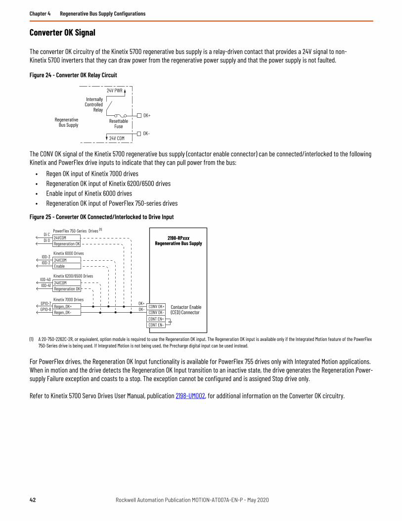
Chapter 4 Regenerative Bus Supply Configurations
Converter OK Signal
The converter OK circuitry of the Kinetix 5700 regenerative bus supply is a relay-driven contact that provides a 24V signal to non-Kinetix 5700 inverters that they can draw power from the regenerative power supply and that the power supply is not faulted.
Figure 24 - Converter OK Relay Circuit
The CONV OK signal of the Kinetix 5700 regenerative bus supply (contactor enable connector) can be connected/interlocked to the following Kinetix and PowerFlex drive inputs to indicate that they can pull power from the bus:
• Regen OK input of Kinetix 7000 drives• Regeneration OK input of Kinetix 6200/6500 drives• Enable input of Kinetix 6000 drives• Regeneration OK input of PowerFlex 750-series drives
Figure 25 - Converter OK Connected/Interlocked to Drive Input
(1) A 20-750-2262C-2R, or equivalent, option module is required to use the Regeneration OK input. The Regeneration OK input is available only if the Integrated Motion feature of the PowerFlex 750-Series drive is being used. If Integrated Motion is not being used, the Precharge digital input can be used instead.
For PowerFlex drives, the Regeneration OK Input functionality is available for PowerFlex 755 drives only with Integrated Motion applications. When in motion and the drive detects the Regeneration OK Input transition to an inactive state, the drive generates the Regeneration Power-supply Failure exception and coasts to a stop. The exception cannot be configured and is assigned Stop drive only.
Refer to Kinetix 5700 Servo Drives User Manual, publication 2198-UM002, for additional information on the Converter OK circuitry.
OK+
OK–
24V PWR
24V COM
InternallyControlled
Relay
RegenerativeBus Supply
Resettable Fuse
CONV OK+CONV OK–CONT EN+CONT EN–
OK+OK–
24VCOMRegeneration OK
IOD-40IOD-41
Kinetix 6200/6500 Drives
Regen_OK+Regen_OK–
Kinetix 7000 DrivesGPIO-7GPIO-8
24VCOMEnable
IOD-3IOD-2
Kinetix 6000 Drives
24VCOMRegeneration OK
Di CDi 0
PowerFlex 750-Series Drives2198-RPxxx
Regenerative Bus Supply
Contactor Enable(CED) Connector
(1)
42 Rockwell Automation Publication MOTION-AT007A-EN-P - May 2020

Regenerative Bus Supply Configurations Chapter 4
Contactor Enable Relay
The contactor-enable circuitry includes a relay-driven contact within the 2198-RPxxx DC-bus power supply. The relay protects the Kinetix 5700 drive system in the event of overloads or other fault conditions.
Figure 26 - Contactor-enable Control String
An AC three-phase mains contactor must be wired in series between the branch circuit protection and the power supply. In addition, the AC three-phase contactor control string must be wired in series with the contactor-enable relay at the contactor-enable terminals.
PowerFlex 750-Series drives are not required to include a contactor-enable control string and they do not have a dedicated contactor enable relay. Although not required, if leveraging Integrated Motion with a PowerFlex 755 drive, we recommend that you configure a digital output from the drive as Contactor Enable and include it in the contactor enable control string.
A Contactor Enable output can be configured in the PowerFlex 755 drive in integrated motion only. The operation of this output is tied to fault processing in the drive. The drive de-energizes the Contactor Enable output when an exception causes the axis to go to the Shutdown state.
Figure 27 - Contactor-enable Relay Circuit
Refer to Kinetix 5700 Servo Drives User Manual, publication 2198-UM002, for additional information on the contactor-enable circuitry.
This configuration is only valid when an auxiliary power supply is used for control power with frames 1…7 drives.
ATTENTION: Wiring the contactor enable relay is required for Kinetix 5700, Kinetix 6x00, and Kinetix 7000 drive systems to help prevent personal injury or damage to Kinetix drive modules. Wire the contactor enable relay into your control string so that:• three-phase power is removed and the power supply or regenerative bus supply is protected under various fault conditions• three-phase power is never applied to the Kinetix 5700 drive system before control power is applied.
ATTENTION: For Kinetix 6000 (400V-class) and Kinetix 6200/6500 drive in common-bus configurations, the contactor enable connections for leader and follower drives must be wired in series to the control string. A contactor or other device that routinely disconnects and reapplies the AC line to the bus supply can cause drive hardware damage. If an input device is used, operation must not exceed two cycles per minute (maximum) or damage can occur to the precharge circuit.
Kinetix 57002198-RPxxx
Regenerative Bus Supply
CONT
EN+
CONT
EN–
GPR2
+GP
R2–
Kinetix 6x002094-BCxx-Mxx-S
Integrated Axis Module
Kinetix 70002099-BMxx-SServo Drive
CONT
EN+
CONT
EN–
STOP *
START *
CR1 *
CR1 *CR1 *
M1 *24V AC/DC
50/60 Hz
* Indicates User Supplied Component
CONT EN-
CONT EN+Normally
OpenRelay
Power Supply
Rockwell Automation Publication MOTION-AT007A-EN-P - May 2020 43

Chapter 4 Regenerative Bus Supply Configurations
System Sizing
These limitations apply to systems supplied by 2198-RPxxx regenerative bus supplies:• The sum of the inverter motor-power cable lengths for all inverters on the same DC bus-sharing group must not exceed 1200 m
(3937 ft) to comply with IEC 61800-3 (category C3) requirements when used with 2198-DBRxx-F line filters. 2198-DBxx-F line filters have a total motor cable length limit of 400 m (1312 ft). See the Kinetix 5700 Servo Drives User Manual, publication 2198-UM002, for additional motor power cable-length limitations.
• The total system capacitance limit is based on the power supply catalog number. DC-bus groups must not exceed the limits as defined in Kinetix and PowerFlex Drive Specifications on page 59.
• If using the 24V DC shared-bus connection system, add another 24V power supply when control input power to a cluster of drive modules exceeds 40 A.
• The Kinetix 5700 system can have multiple drive clusters in a single DC-bus group. See the Kinetix 5700 Servo Drives User Manual, publication 2198-UM002, for more information on extended clusters.
Refer to the Kinetix 5700 Servo Drives User Manual, publication 2198-UM002, for additional information on system sizing guidelines.
The motor required for a particular application determines the drive required for full motor performance. For best results, use the Motion Analyzer system sizing and selection tool, available at https://motionanalyzer.rockwellautomation.com/.
Capacitance Sizing
Total system capacitance is the sum of all internal capacitance values from each of the drive modules (AC drives, single-axis inverters, dual-axis inverters, power supplies, and capacitor modules) in the same DC-bus group.
The total system capacitance must be less than the maximum supported DC-bus capacitance value of the power supply (refer to Kinetix and PowerFlex Drive Specifications on page 59).
External bus capacitance is the total system capacitance minus the power supply capacitance. The external bus capacitance must be entered into the Logix Designer application for a regenerative power supply to maintain proper control.
All drives have a DC-bus capacitance that is proportional to their power ratings. When used in a common DC-bus configuration, these capacitors are directly connected in parallel. This connection results in the DC-bus ripple being shared proportional to the power rating of the drive. When the ratio of the capacitance to the drive-rated current is consistent, it provides the best DC-bus ripple sharing.
For 400/480V AC, the target ratio is 40 µF/A ±10% or greater. For all drives supported in this publication, the target ratio is met when a capacitor module is used to extend the DC-bus, proper DC-bus cable length guidelines are followed, and low-inductance DC cable is used. See DC-bus Connections on page 8 for more information.
Circuit Protection
Do not daisy chain drives to share DC-bus fusing. Configure the shared DC-bus in a star configuration to enable proper fusing. Use fast semiconductor fuses in the DC links to minimize destructive energy in the event of a part or control malfunction. Size fuses to handle large peak currents at the end of precharge.
• See Kinetix and PowerFlex Drive Specifications on page 59 for the recommended common DC-bus circuit protection devices.• See the Kinetix 5700 Servo Drives User Manual, publication 2198-UM002, for recommended AC input circuit protection for the Bulletin
2198 power supply.
IMPORTANT If your total system capacitance value exceeds the maximum supported capacitance value of the regenerative bus supply, perform one of the following:• Increase the size of the 2198-RPxxx regenerative bus supply• Decrease the total system capacitance by removing inverters or capacitor modules from the DC-bus group• Separate clusters into multiple DC-bus groups
44 Rockwell Automation Publication MOTION-AT007A-EN-P - May 2020

Chapter 5
Regenerative Bus Supply Configurations With Active Shunt
This system also uses a PWM-controlled IGBT converter for regeneration of power to the AC line. However, in this configuration some regenerative DC-bus energy flows to the incoming AC line, but DC-bus energy that is not regenerated is dissipated to an external shunt resistor (braking) unit. This configuration provides low AC-line harmonics and can be used to meet IEEE-519. Contact our Encompass™ Partners for these shunt resistor (braking) products.
Supported Products
At the time of publication, the following products are supported.
When applicable, the drive's internal IGBT can be used with a passive shunt.
Table 32 - Kinetix 5700 Regenerative Bus Supply Modules
Regenerative Bus SupplyCat. No. Supported Drives
• 2198-RP088• 2198-RP200• 2198-RP263• 2198-RP312
PowerFlex® 750-Series: Frames 1…6 (1)
(1) PowerFlex 750-Series (Frames 5 and 6) DC input version drives with precharge must be selected.
Kinetix® 7000: 2099-BM06-S…2099-BM12-S
Kinetix 6000 and Kinetix 6200/6500: All 460V configurations (2)
(2) Kinetix 6000 configurations require firmware revision 1.92 or later.
Drive Family Internal Brake IGBTPowerFlex 750-Series Standard on Frames 1…5, optional on Frame 6.Kinetix 7000 No internal brake IGBT.Kinetix 6000 (400V-class) and Kinetix 6200/6500 Internal bus regulation cannot be used.
IMPORTANT The internal IGBT in Kinetix 6000 (460V) drives and Kinetix 6200/6500 drives are disabled in Common Bus Follower mode.
Rockwell Automation Publication MOTION-AT007A-EN-P - May 2020 45

Chapter 5 Regenerative Bus Supply Configurations With Active Shunt
Typical System Configuration
In this example, standalone AC drives with an external passive shunt, Kinetix 6x00 drives, and Kinetix 7000 drives receive DC-bus power from the 2198-RP200 regenerative bus supply.
Figure 28 - Regenerative Bus Supply with Standalone AC Drives, Kinetix 6x00 Drives, Kinetix 7000 Drives, and External Passive Shunt
(1) A line reactor can be required. For line reactor selection, see the Kinetix 5700 Servo Drives User Manual, publication 2198-UM002.(2) Kinetix 5700 regenerative bus supplies require an isolation transformer when connected to corner-grounded or ungrounded facility power.(3) Kinetix 5700 regenerative bus supplies in mixed common-bus systems require a DC-bus conditioner module in the power supply cluster.(4) External passive shunt resistor. For minimum ohms with PowerFlex 750-Series drives, see PowerFlex Dynamic Braking Resistor Calculator Application Technique, publication PFLEX-AT001.(5) Connect the shunt resistor (braking IGBT) to the largest frame size drive.
Table 33 - Special Bus Requirements
Drawing Designation Supported Drives Special Bus RequirementsAC Drive 1 PowerFlex 750-Series: Frames 1…6
NoneAC Drive 2
PowerFlex 750-Series: Frames 1…6Kinetix 7000: 2099-BM06-S…2099-BM08-SKinetix 7000: 2099-BM09-S…2099-BM12-S
Kinetix 6000 andKinetix 6200/6500 drives
Kinetix 6000: All 460V configurations (1)
(1) No internal precharge. Drives must be placed in common-bus follower configuration.
NoneKinetix 6200/6500: All 460V configurations (1)
2198
-RP2
00(po
wer s
upply
clus
ter)
RegenerativeBus Supply
2198
-CAP
MOD-
2240 DC+ DC-
M
DC+ DC-
M
AC Drive 1 AC Drive 2
M M M
DC+ DC-
ReactorLine Capacitor
Module
DC Bus
BR
Kinetix 6000 orKinetix 6200/6500 Drives
M
Integrated Axis Module
Axis Modules
Three-phaseSource Contactor
Three-phase
2198
-DCB
USCO
ND-R
P312
DC-bus ConditionerModule
(4) (5)
(1)(2)(3)
46 Rockwell Automation Publication MOTION-AT007A-EN-P - May 2020

Regenerative Bus Supply Configurations With Active Shunt Chapter 5
In this example, standalone AC drives, Kinetix 6x00 drives, and Kinetix 7000 drives receive DC-bus power from the 2198-RP200 regenerative bus supply. An external active shunt is connected to the regenerative bus supply active-shunt (RC) connector.
Figure 29 - Regenerative Bus Supply with Standalone AC Drives, Kinetix 6x00 Drives, Kinetix 7000 Drives, and External Active Shunt
(1) A line reactor can be required. For line reactor selection, see the Kinetix 5700 Servo Drives User Manual, publication 2198-UM002.(2) Kinetix 5700 regenerative bus supplies require an isolation transformer when connected to corner-grounded or ungrounded facility power.(3) Due to the 10 A connector current rating, connections to the 2198-RPxxx (RC connector) are limited to only Powerohm PKBxxx active shunts rated at 7 kW or less.(4) External active shunt module. For active shunt mounting and wiring considerations, see the Kinetix 5700 Servo Drives User Manual, publication 2198-UM002.(5) Kinetix 5700 regenerative bus supplies in mixed common-bus systems require a DC-bus conditioner module in the power supply cluster.
Table 34 - Special Bus Requirements
Drawing Designation Supported Drives Special Bus Requirements
AC DrivePowerFlex 750-Series: Frames 1…6
NoneKinetix 7000: 2099-BM06-S…2099-BM08-SKinetix 7000: 2099-BM09-S…2099-BM12-S
Kinetix 6000 and Kinetix 6200/6500 drives
Kinetix 6000: All 460V configurations (1)
(1) No internal precharge. Drives must be placed in common-bus follower configuration.
NoneKinetix 6200/6500: All 460V configurations (1)
2198
-RP2
00(po
wer s
upply
clus
ter)
RegenerativeBus Supply
2198
-CAP
MOD-
2240
Three-phaseSource
DC+ DC-
M
DC+ DC-
M
AC Drive 1 AC Drive 2
M M M
DC+ DC-
ReactorLine
ContactorThree-phase Capacitor
Module
DC Bus
Kinetix 6000 orKinetix 6200/6500 Drives
M
Integrated Axis Module
Axis Modules
2198
-DCB
USCO
ND-R
P312
DC-bus ConditionerModule (5)
(1)(2)
(3) (4)
Rockwell Automation Publication MOTION-AT007A-EN-P - May 2020 47

Chapter 5 Regenerative Bus Supply Configurations With Active Shunt
In this example, standalone AC drives, Kinetix 6x00 drives, and Kinetix 7000 drives receive DC-bus power from the 2198-RP200 regenerative bus supply. An external active shunt is connected to the DC-bus studs of an accessory module.
Figure 30 - Regenerative Bus Supply with Standalone AC Drives, Kinetix 6x00 Drives, Kinetix 7000 Drives, and External Active Shunt
(1) A line reactor can be required. For line reactor selection, see the Kinetix 5700 Servo Drives User Manual, publication 2198-UM002.(2) Kinetix 5700 regenerative bus supplies require an isolation transformer when connected to corner-grounded or ungrounded facility power.(3) Kinetix 5700 regenerative bus supplies in mixed common-bus systems require a DC-bus conditioner module in the power supply cluster.(4) External active shunt module. For active shunt mounting and wiring considerations, see the Kinetix 5700 Servo Drives User Manual, publication 2198-UM002.
General Considerations
This section includes information on AC line impedance, disconnect switch connections, and ground screw/jumper settings, depending on the drive family.
• All system components (bus supply and PowerFlex or Kinetix drives) must be selected for the same AC-line voltage. • Low-inductance type DC-bus must be used. See DC-bus Connections on page 8 for details. • To be used in a common-bus system with a Kinetix 5700 bus supply, the Kinetix 6000 or Kinetix 6200/6500 drive systems must be
configured as common-bus follower (internal IGBT for shunting is disabled).
• The Kinetix 7000 drive internal dynamic brake IGBT is not used by the drive main control for bus regulation, therefore any type of regulation must come from an external source.
• Refer to Additional Resources on page 81 for user documentation with the maximum motor cable length requirements of the drives specific to your application.
Table 35 - Special Bus Requirements
Drawing Designation Supported Drives Special Bus Requirements
AC DrivePowerFlex 750-Series: Frames 1…6
NoneKinetix 7000: 2099-BM06-S…2099-BM08-SKinetix 7000: 2099-BM09-S…2099-BM12-S
Kinetix 6000 and Kinetix 6200/6500 drives
Kinetix 6000: All 460V configurations (1)
(1) No internal precharge. Drives must be placed in common-bus follower configuration.
NoneKinetix 6200/6500: All 460V configurations (1)
ATTENTION: The incorrect use or configuration of third party assemblies can result in reduced system reliability and drive damage.
IMPORTANT Do not include the 2094-BSP2 shunt module on the 2094 power rail.
2198
-RP2
00(po
wer s
upply
clus
ter)
RegenerativeBus Supply
2198
-CAP
MOD-
2240
Three-phaseSource
DC+ DC-
M
DC+ DC-
M
AC Drive 1 AC Drive 2
M M M
DC+ DC-
ReactorLine
ContactorThree-phase Capacitor
Module
DC Bus
External ActiveShunt
BR
BR1 BR2
DC+ DC-
Kinetix 6000 orKinetix 6200/6500 Drives
M
Integrated Axis Module
Axis Modules
2198
-DCB
USCO
ND-R
P312
DC-bus ConditionerModule
(1)(2)(3)
(4)
48 Rockwell Automation Publication MOTION-AT007A-EN-P - May 2020

Regenerative Bus Supply Configurations With Active Shunt Chapter 5
AC Line Impedance Considerations
In the following use cases, an additional transformer or line reactor is required due to faults or potential damage associated with AC line disturbances:
• Installation site has switched power-factor correction capacitors.• Installation site has lightning strikes or voltage spikes in excess of 6000V peak.• Installation site has power interruptions or voltage dips in excess of 200V AC.• The transformer kVA is more than 10 times larger than the drive kVA or the percent source impedance relative to each converter is
less than 0.5%.
In the following use cases, a line reactor is required due to faults associated with sharing AC line-input on multiple converters:• Repetitive AC input line-voltage notching is present. For example, if silicon-controlled rectifier drive is connected to the same AC
input power source.- In drive systems that include the regenerative bus supply, repetitive AC line voltage notching can cause the integrated AC line filter
to overheat and result in FLT S18 converter overtemperature faults.• Powering multiple (two or more) regenerative bus supplies from the same AC input-power source.
- Switching ripple from each regenerative bus supply can interfere with other regenerative bus supplies on the same AC input power source.
• Powering 2198-Pxxx DC-bus power supply and 2198-RPxxx regenerative bus supply from the same AC input-power source.- Switching ripple from the regenerative bus supply can impact the temperature of DC-bus capacitors in the DC-bus power supply. In
this use case, a line reactor is required in the AC input-power string leading to the regenerative bus supply.
Refer to Kinetix 5700 Servo Drives User Manual, publication 2198-UM002, for additional AC line impedance considerations.
Disconnect Switch Considerations
If a disconnect switch is used between the common DC-bus and a PowerFlex 750-Series drive input, connect an auxiliary contact on the disconnect switch to a digital input of the drive. The corresponding digital input must be set to Precharge Enable. This setting provides the proper precharge interlocking, which guards against possible damage to the drive when reconnecting the drive to an energized DC-bus. Under this condition, the drives must have an internal or externally supplied precharge. Precharge handshaking is required before inverter operation.
If DC input is supplied to 2099-BM09-S, 2099-BM10-S, 2099-BM11-S, or 2099-BM12-S drives, the precharge capability must be provided at the system level. Disconnect switches must not be used between the input of the drive and a common DC-bus without the use of an external precharge device.
When an external precharge device is required, a fuse combination switch can be used. These switches provide precharge of capacitive loads, have integrated fuse protection, and perform automatic pre-load type functions with an internal coil.
Table 36 - PowerFlex 750-Series Drive Precharge Parameter
ParameterDigital Input
Number Setting189 [DI Precharge] See PowerFlex 750-Series AC Drives Programming Manual, publication 750-PM001.
ATTENTION: To avoid personal injury and/or equipment damage, make sure installation complies with specifications regarding wire types, conductor sizes, branch circuit protection, and disconnect devices. The National Electrical Code (NEC) and local codes outline provisions for safely installing electrical equipment.
ATTENTION: The Kinetix 6000 (400V-class), Kinetix 6200/6500, Kinetix 7000, and PowerFlex 750-Series (Frames 5 and 6) AC input drives have no method for you to control the precharge sequence. To avoid sever drive and/or equipment damage due to uncontrolled precharge, do not connect these drives to an energized bus. If a disconnect switch is used between the inputs of the drives and the common DC-bus, an external precharge device must be used.
Rockwell Automation Publication MOTION-AT007A-EN-P - May 2020 49

Chapter 5 Regenerative Bus Supply Configurations With Active Shunt
Input and Output Signals
For the Kinetix 7000 drives, wire the control and interface signals on the General Purpose Relay (GPR) and General Purpose I/O (GPIO) connectors as described in the following tables. See the Kinetix 7000 Servo Drives User Manual, publication 2099-UM001, for more information on the terminal block connections.
In common bus configurations, a REGEN connection on the General Purpose I/O connector is also required for the drives. This connection must be wired in series to the control string, and also wired from the regenerative bus supply to the Kinetix 7000 drive to indicate bus voltage is present.
Table 37 - General Purpose Relay Connections
Signal Terminal Description Recommended Wire Sizemm2 (AWG)
Strip Lengthmm (in.)
Torque ValueN•m (lb•in)
DRIVE OK+ 5 Programmable N.O. Relay 2 output 0.75 (18)(stranded wire with ferrule)1.5 (16)(solid wire)
7.0 (0.275) 0.235 (2.0)DRIVE OK- 6 Programmable Relay 2 common
Table 38 - General Purpose I/O Connections
Signal Terminal Description Recommended Wire Sizemm2 (AWG)
Strip Lengthmm (in.)
Torque ValueN•m (lb•in)
Regen_OK+ 7 Regenerative power supply status 0.75 (18)(stranded wire with ferrule)1.5 (16)(solid wire)
7.0 (0.275) 0.235 (2.0)Regen_OK- 8 Regenerative power supply status common
ATTENTION: For the Kinetix 7000 drives, wiring the DRIVE OK signal on the General Purpose Relay is required. To avoid injury or damage to the drive, wire the DRIVE OK relay into your control string.
50 Rockwell Automation Publication MOTION-AT007A-EN-P - May 2020

Regenerative Bus Supply Configurations With Active Shunt Chapter 5
Drive Ground Jumper Settings
Set the ground jumpers for the Kinetix 6000 (400V-class), Kinetix 6200/6500, and Kinetix 7000 drives according to the following tables. Refer to Additional Resources on page 81 for the user manual with instructions on how to set the ground jumpers/screws for your servo drive.
PowerFlex 750-Series drives contain protective metal-oxide varistors (MOV) and common mode capacitors referenced to ground. To guard against unstable operation and/or damage, the drive must be properly configured as shown in the following table.
For instructions on how to disconnect the PE jumpers, refer to PowerFlex 750-Series Power Jumpers Installation Instructions, publication 750-IN011.
Table 39 - Ground Jumper Settings for Kinetix 6000 (400V-class) and Kinetix 6200/6500 Drives
Ground Configuration Ground Jumper Setting (1)
(1) When powered by 2198-RPxxx regenerative bus supply.
Grounded (wye)
Set for ungrounded power• AC-fed ungrounded• Corner grounded• Impedance grounded• DC-bus from active converter
Table 40 - Ground Jumper Settings for Kinetix 7000 Drives
Ground Configuration Ground Jumper Setting (1)
(1) When powered by 2198-RPxxx regenerative bus supply.
Grounded (wye)
Removed• AC-fed ungrounded• Corner grounded• Impedance grounded• DC-bus from active converter
Table 41 - Power Jumper Settings for PowerFlex 750-Series Drives (Frames 1…6)
Ground Configuration Ground Jumper Setting (1)
(1) When powered by 2198-RPxxx regenerative bus supply.
Grounded (wye)
• Jumper PE-A disconnected (MOV/input filter caps)• Jumper PE-B disconnected (DC-bus common mode caps)
• AC-fed ungrounded• Corner grounded• Impedance grounded• DC-bus from active converter
Rockwell Automation Publication MOTION-AT007A-EN-P - May 2020 51

Chapter 5 Regenerative Bus Supply Configurations With Active Shunt
Active Shunt Considerations
External active shunts are required in the following use cases:• The 2198-RPxxx regenerative bus supply provides DC-bus power while
DC-bus regulation is not enabled.• One permanent magnet motor runs above its bus overvoltage speed. See Kinetix 5700 Servo Drives User Manual, publication
2198-UM002, information on the Field Weakening Mode feature.• One permanent magnet motor drives a vertical load that could make the motor accelerate above the bus overvoltage speed during a
fault condition.• Any condition where total shared DC-bus regenerative power is greater than the 2198-RPxxx regenerative bus supply capacity. For
example, consider a peak-power stopping condition.• The 2198-RPxxx regenerative bus supply is operating with DC-bus regulation enabled and the regenerative bus supply loses three-
phase AC input power, 24V DC input power, or has a fault condition.
Active shunts are available from the Rockwell Automation Encompass partner Powerohm Resistors, Inc. See http://www.powerohm.com for more information on Powerohm active shunts.
ATTENTION: To avoid damage to the Kinetix 5700 drive system, wire the active shunt thermal switch to a digital input on the power supply and configure the Shunt Thermal Switch OK function in the Logix Designer application.
ATTENTION: DC-bus failure can cause damage to all drive modules in the bus group, not just the inverter connected to the motor.
IMPORTANT Powerohm Bulletin PKBxxx active shunt modules use built-in internal brake resistors. Bulletin PWBxxx active shunt modules require appropriately sized external brake resistors.
Table 42 - Compatible Active Shunt Specifications (internal brake resistor)
Kinetix 5700 Power SupplyPowerohm ResistorsCat. No. (1)
(1) How the Powerohm PKBxxx shunts connect to the 2198-RPxxx regenerative bus supply is explained in 2198-RPxxx Bus Supply with External Active Shunt (built-in brake resistor) on page 54.
Input Voltage,nom
Turn -onBus Voltage
Continuous PowerkW
Resistance(internal)Ω
Resistance(minimum)Ω
Continuous CurrentAmps
Peak CurrentAmps
2198-RPxxx regenerative bus supply when DC-bus regulation is not enabled.
PKB005
480V AC
750V DC1.50 108 – 2.00 6.9
PKB010 2.06 52.7 – 2.75 14.2PKB050 7.00 10.5 – 9.30 71.4
2198-RPxxx regenerative bus supply when DC-bus regulation is enabled.
PKB005-800800V DC
1.50 108 – 1.88 7.4PKB010-800 2.06 52.7 – 2.58 15.2PKB050-800 7.00 10.5 – 8.72 76.2
Table 43 - Compatible Active Shunt Specifications (no internal brake resistor)
Kinetix 5700 Power SupplyPowerohm ResistorsCat. No. (1)
(1) How the Powerohm PWBxxx shunts connect to the 2198-RPxxx regenerative bus supply is explained in 2198-RPxxx Bus Supply with External Active Shunt (external brake resistor) on page 55
Input Voltage,nom
Turn -onBus Voltage
Continuous PowerkW
Resistance(internal)Ω
Resistance(minimum)Ω
Continuous CurrentAmps
Peak CurrentAmps
2198-RPxxx regenerative bus supply when DC-bus regulation is not enabled.
PWB035
480V AC750V DC
26.25 – 7.5 35 100PWB110 82.5 – 2.5 110 300
2198-RPxxx regenerative bus supply when DC-bus regulation is enabled.
PWB035-800800V DC
26.25 – 8.0 35 100PWB110-800 82.5 – 2.7 110 300
ATTENTION: Do not use Powerohm active-shunt modules at input line voltages that exceed 528V AC. Active-shunt thermal-overload shutdown can occur if input line voltage exceeds 528V AC.
52 Rockwell Automation Publication MOTION-AT007A-EN-P - May 2020

Regenerative Bus Supply Configurations With Active Shunt Chapter 5
Kinetix 5700 Regenerative Bus Supply Considerations
When extending the DC-bus from the power supply cluster, a capacitor module must be used to extend the bus. Refer to Kinetix 5700 Accessory Modules on page 71 for more information on when accessory modules are required.
Shunt Connections
Figure 31 - RC Connector Wiring
You can make active shunt connections in drive systems that include the regenerative bus supply and Powerohm PKBxxx-800 or PWBxxx-800 active shunts at the external DC-bus studs on accessory modules.
IMPORTANT Regenerative bus supplies do not require an isolation transformer for three-phase input power unless they are connected to corner-grounded or ungrounded facility power.
IMPORTANT 2198-RPxxx regenerative bus supplies do not support passive shunts. Make active shunt connections to the 2198-RPxxx regenerative bus supply at the active shunt (RC) connector or the external DC-bus studs on accessory modules, depending on the shunt type.
Table 44 - Active Shunt (RC) Connector Specifications
Regenerative Bus SupplyCat. No. Pin Signal Continuous (1) Current,
max
(1) This connector applies to only Powerohm PKBxxx-xxx active shunts rated at 7 kW or less.
Recommended Wire Sizemm2 (AWG)
Strip Lengthmm (in.)
Torque ValueN•m (lb•in)
2198-RPxxx RC-1RC-2
DC–DC+ 10 A 2.5…6
(14…10) 12.0 (0.47) 0.5…0.6(4.4…5.3)
IMPORTANT Due to the 10 A connector current rating, connections to the RC connector are limited to only Powerohm PKBxxx-xxx active shunts rated at 7 kW or less. All other PKBxxx-xxx and PWBxxx-xxx active shunt connections must be made to the 2198-CAPMOD-2240 capacitor module.
12
2198-RPxxx Regenerative Bus SupplyTop View
Active Shunt(RC) Connector Plug
Rockwell Automation Publication MOTION-AT007A-EN-P - May 2020 53

Chapter 5 Regenerative Bus Supply Configurations With Active Shunt
Accessory modules are equipped with spacers that slide onto the M8 studs. When the system configuration includes external DC-bus and active shunt connections, external DC-bus connections are made below the spacer and active shunt connections are made above the spacer.
Figure 32 - Active Shunt Connections
(1) An external active shunt can be wired to any of the accessory modules. See Kinetix 5700 Servo Drives User Manual, publication 2198-UM002, for more information on mounting and accessory module example configurations. The 2198-CAPMOD-2240 capacitor module is preferred because it provides additional system capacitance.
(2) Position flexible bus-bars (when two accessory modules are used) below the DC-bus lug connections. The flexible bus-bars are used to parallel the extended DC-bus with another accessory module in 208 A systems (not required when only one accessory module is used in 104 A systems). Flexible bus-bars are included with 2198-CAPMOD-DCBUS-IO extension modules or you can order 2198-KITCON-CAPMOD2240 or 2198-KITCON-DCBUSCOND replacement kits.
For compatible Powerohm active shunts paired with the 2198-RPxxx regenerative bus supply, refer to Kinetix 5700 Servo Drives User Manual, publication 2198-UM002.
Figure 33 - 2198-RPxxx Bus Supply with External Active Shunt (built-in brake resistor)
(1) Configure any available digital input as Shunt Thermal Switch OK. See the Kinetix 5700 Servo Drives User Manual, publication2198-UM002, for more information on configuring digital inputs.
(2) Powerohm PKB050 and PKB050-800 shunts require 120V AC between pins 9 and 10 to supply power to the cooling fans.
See Knowledgebase document 1082776 for more information on wiring to these Powerohm Bulletin PKBxxx active shunts.
ATTENTION: To avoid damage to the Kinetix 5700 drive system, wire the active shunt thermal switch to a digital input on the power supply and configure the Shunt Thermal Switch OK function in the Logix Designer application.
2198-DCBUSCOND-RP312 2198-CAPMOD-2240 or 2198-CAPMOD-DCBUS-IO (1)Accessory Modules(2198-CAPMOD-2240 capacitor module is shown)
Active ShuntLug Connections
(above spacer)
DC-busLug Connections andFlexible Bus-bars (2)
(below spacer)
Spacer
DC+DC–
120V AC910
34
DC+
DC–
INxCOM 24V DC
(1)(2)
2198-RPxxx Regenerative Bus Supply
PowerohmBulletin PKBxxx-xxx
Active Shunt Module
Fault Contact
Digital Input(IOD) Connector
External DC-bus Resistor
4.6 m (15 ft) Maximum Cable Length2198-xxxx-ERSx
Inverter2198-CAPMOD-2240Capacitor Module
54 Rockwell Automation Publication MOTION-AT007A-EN-P - May 2020
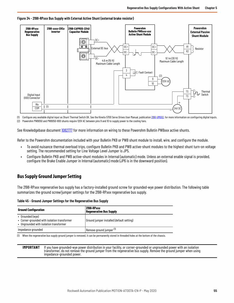
Regenerative Bus Supply Configurations With Active Shunt Chapter 5
Figure 34 - 2198-RPxxx Bus Supply with External Active Shunt (external brake resistor)
(1) Configure any available digital input as Shunt Thermal Switch OK. See the Kinetix 5700 Servo Drives User Manual, publication 2198-UM002, for more information on configuring digital inputs.(2) Powerohm PWB050 and PWB050-800 shunts require 120V AC between pins 9 and 10 to supply power to the cooling fans.
See Knowledgebase document 1082777 for more information on wiring to these Powerohm Bulletin PWBxxx active shunts.
Refer to the Powerohm documentation included with your Bulletin PKB or PWB shunt module to install, wire, and configure the module.• To avoid nuisance thermal overload trips, configure Bulletin PKB and PWB active-shunt modules to the highest shunt turn-on voltage
setting. The recommended setting for Line Voltage Level Jumper is JP5.• Configure Bulletin PKB and PWB active-shunt modules in Internal (automatic) mode. Unless an external enable signal is provided,
configure the Brake Enable Jumper in Internal (automatic) mode (JP6 is in the downward position).
Bus Supply Ground Jumper Setting
The 2198-RPxxx regenerative bus supply has a factory-installed ground screw for grounded-wye power distribution. The following table summarizes the ground screw/jumper settings for the 2198-RPxxx regenerative bus supply.
Table 45 - Ground Jumper Settings for the Regenerative Bus Supply
Ground Configuration 2198-RPxxx Regenerative Bus Supply
• Grounded (wye)• Corner-grounded with isolation transformer• Ungrounded with isolation transformer
Ground jumper installed (default setting)
Impedance grounded Remove ground jumper (1)
(1) When the regenerative bus supply ground jumper is removed, it can be permanently stored in threaded holes at the bottom of the chassis.
IMPORTANT If you have grounded-wye power distribution in your facility, or corner-grounded or ungrounded power with an isolation transformer, do not remove the ground jumper from the regenerative bus supply. Remove the ground jumper when using impedance-grounded power.
34
R1R2
DC+
DC–
DC+
DC–
DC+
DC–
INxCOM (1) 24V DC
120V AC910
(2)
TSTS
External DC-bus
Powerohm External Passive
Shunt Module
Resistor
Thermal SwitchDigital Input
(IOD) Connector
Powerohm Bulletin PWBxxx-xxxActive Shunt Module
4.6 m (15 ft) Maximum Cable Length
9.1 m (30 ft) Maximum Cable Length
2198-xxxx-ERSxInverter
Fault Contact
2198-RPxxx Regenerative
Bus Supply
2198-CAPMOD-2240Capacitor Module
Rockwell Automation Publication MOTION-AT007A-EN-P - May 2020 55

Chapter 5 Regenerative Bus Supply Configurations With Active Shunt
Converter OK Signal
The converter OK circuitry of the Kinetix 5700 regenerative bus supply is a relay-driven contact that provides a 24V signal to non-Kinetix 5700 inverters that they can draw power from the regenerative power supply and that the power supply is not faulted.
Figure 35 - Converter OK Relay Circuit
The CONV OK signal of the Kinetix 5700 regenerative bus supply (contactor enable connector) can be connected/interlocked to the following Kinetix and PowerFlex drive inputs to indicate that they can pull power from the bus:
• Regen OK input of Kinetix 7000 drives• Regeneration OK input of Kinetix 6200/6500 drives• Enable input of Kinetix 6000 drives• Regeneration OK of PowerFlex 750-series drives
Figure 36 - Converter OK Connected/Interlocked to Drive Input
(1) The Regeneration OK input is available only if the Integrated Motion feature of the PowerFlex 750-Series drive is being used. If Integrated Motion is not being used, the Precharge digital input can be used instead.
For PowerFlex drives, the Regeneration OK Input functionality is available for PowerFlex 755 drives only with Integrated Motion applications. When in motion and the drive detects the Regeneration OK Input transition to an inactive state, the drive generates the Regeneration Power-supply Failure exception and coasts to a stop. The exception cannot be configured and is assigned Stop drive only.
Refer to Kinetix 5700 Servo Drives User Manual, publication 2198-UM002, for additional information on the Converter OK circuitry.
OK+
OK–
24V PWR
24V COM
InternallyControlled
Relay
RegenerativeBus Supply
Resettable Fuse
CONV OK+CONV OK–CONT EN+CONT EN–
OK+OK–
24VCOMRegeneration OK
IOD-40IOD-41
Kinetix 6200/6500 Drives
Regen_OK+Regen_OK–
Kinetix 7000 DrivesGPIO-7GPIO-8
24VCOMEnable
IOD-3IOD-2
Kinetix 6000 Drives
24VCOMRegeneration OK
Di CDi 0
PowerFlex 750-Series Drives
2198-RPxxxRegenerative Bus Supply
Contactor Enable(CED) Connector
(1)
56 Rockwell Automation Publication MOTION-AT007A-EN-P - May 2020
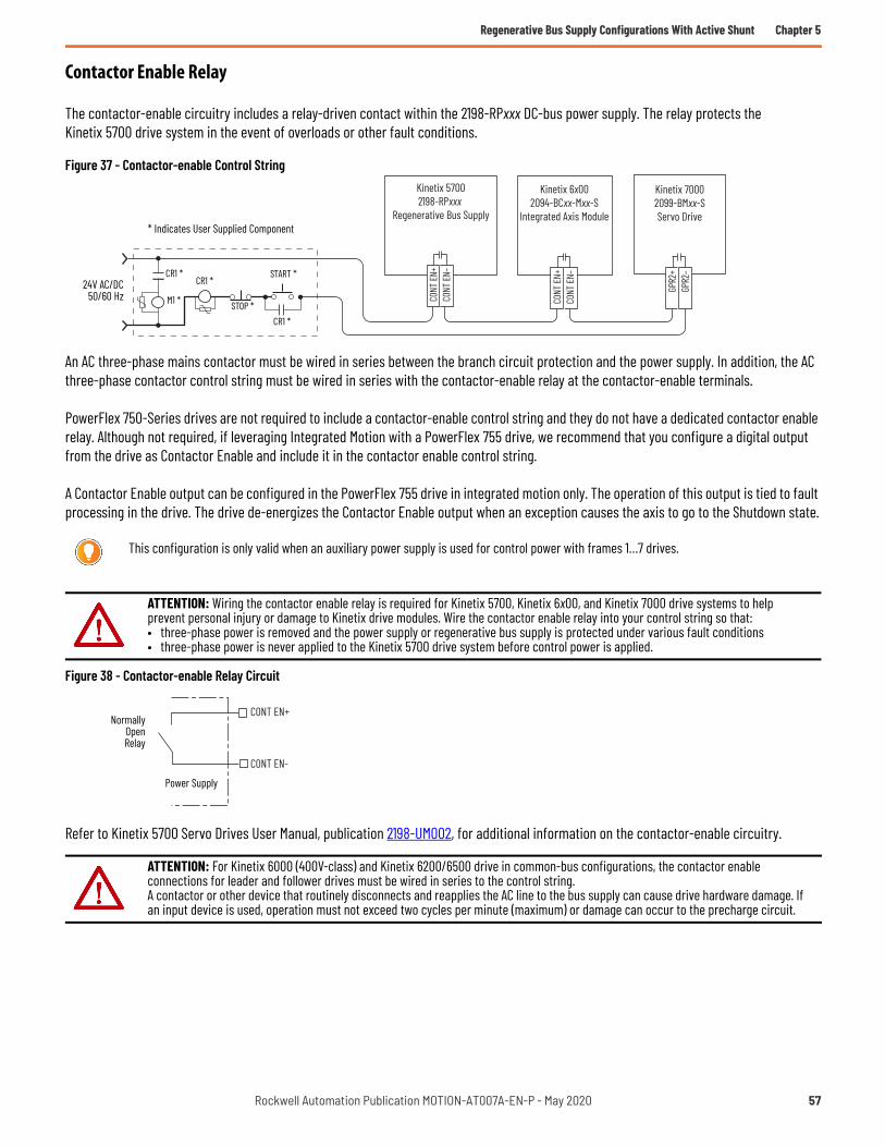
Regenerative Bus Supply Configurations With Active Shunt Chapter 5
Contactor Enable Relay
The contactor-enable circuitry includes a relay-driven contact within the 2198-RPxxx DC-bus power supply. The relay protects the Kinetix 5700 drive system in the event of overloads or other fault conditions.
Figure 37 - Contactor-enable Control String
An AC three-phase mains contactor must be wired in series between the branch circuit protection and the power supply. In addition, the AC three-phase contactor control string must be wired in series with the contactor-enable relay at the contactor-enable terminals.
PowerFlex 750-Series drives are not required to include a contactor-enable control string and they do not have a dedicated contactor enable relay. Although not required, if leveraging Integrated Motion with a PowerFlex 755 drive, we recommend that you configure a digital output from the drive as Contactor Enable and include it in the contactor enable control string.
A Contactor Enable output can be configured in the PowerFlex 755 drive in integrated motion only. The operation of this output is tied to fault processing in the drive. The drive de-energizes the Contactor Enable output when an exception causes the axis to go to the Shutdown state.
Figure 38 - Contactor-enable Relay Circuit
Refer to Kinetix 5700 Servo Drives User Manual, publication 2198-UM002, for additional information on the contactor-enable circuitry.
This configuration is only valid when an auxiliary power supply is used for control power with frames 1…7 drives.
ATTENTION: Wiring the contactor enable relay is required for Kinetix 5700, Kinetix 6x00, and Kinetix 7000 drive systems to help prevent personal injury or damage to Kinetix drive modules. Wire the contactor enable relay into your control string so that:• three-phase power is removed and the power supply or regenerative bus supply is protected under various fault conditions• three-phase power is never applied to the Kinetix 5700 drive system before control power is applied.
ATTENTION: For Kinetix 6000 (400V-class) and Kinetix 6200/6500 drive in common-bus configurations, the contactor enable connections for leader and follower drives must be wired in series to the control string. A contactor or other device that routinely disconnects and reapplies the AC line to the bus supply can cause drive hardware damage. If an input device is used, operation must not exceed two cycles per minute (maximum) or damage can occur to the precharge circuit.
Kinetix 57002198-RPxxx
Regenerative Bus Supply
CONT
EN+
CONT
EN–
GPR2
+GP
R2–
Kinetix 6x002094-BCxx-Mxx-S
Integrated Axis Module
Kinetix 70002099-BMxx-SServo Drive
CONT
EN+
CONT
EN–
STOP *
START *
CR1 *
CR1 *CR1 *
M1 *24V AC/DC
50/60 Hz
* Indicates User Supplied Component
CONT EN-
CONT EN+Normally
OpenRelay
Power Supply
Rockwell Automation Publication MOTION-AT007A-EN-P - May 2020 57

Chapter 5 Regenerative Bus Supply Configurations With Active Shunt
System Sizing
These limitations apply to systems supplied by 2198-RPxxx regenerative bus supplies:• The sum of the inverter motor-power cable lengths for all inverters on the same DC bus-sharing group must not exceed 1200 m (3937
ft) to comply with IEC 61800-3 (category C3) requirements when used with 2198-DBRxx-F line filters. 2198-DBxx-F line filters have a total motor cable length limit of 400 m (1312 ft). See the Kinetix 5700 Servo Drives User Manual, publication 2198-UM002, for additional motor power cable-length limitations.
• The total system capacitance limit is based on the power supply catalog number. DC-bus groups must not exceed the limits as defined in Kinetix and PowerFlex Drive Specifications on page 59.
• If using the 24V DC shared-bus connection system, add another 24V power supply when control input power to a cluster of drive modules exceeds 40 A.
• The Kinetix 5700 system can have multiple drive clusters in a single DC-bus group. See the Kinetix 5700 Servo Drives User Manual, publication 2198-UM002, for more information on extended clusters.
Refer to the Kinetix 5700 Servo Drives User Manual, publication 2198-UM002, for additional information on system sizing guidelines.
The motor required for a particular application determines the drive required for full motor performance. For best results, use Motion Analyzer system sizing and selection tool, available at https://motionanalyzer.rockwellautomation.com/.
Capacitance Sizing
Total system capacitance is the sum of all internal capacitance values from each of the drive modules (AC drives, single-axis inverters, dual-axis inverters, power supplies, and capacitor modules) in the same DC-bus group.
The total system capacitance must be less than the maximum supported DC-bus capacitance value of the power supply (refer to Kinetix and PowerFlex Drive Specifications on page 59).
External bus capacitance is the total system capacitance minus the power supply capacitance. The external bus capacitance must be entered into the Logix Designer application for a regenerative power supply to maintain proper control.
All drives have a DC-bus capacitance that is proportional to their power ratings. When used in a common DC-bus configuration, these capacitors are directly connected in parallel. This connection results in the DC-bus ripple being shared proportional to the power rating of the drive. When the ratio of the capacitance to the drive-rated current is consistent, it provides the best DC-bus ripple sharing.
For 400/480V AC, the target ratio is 40 µF/A ±10% or greater. For all drives supported in this publication, the target ratio is met when a capacitor module is used to extend the DC-bus, proper DC-bus cable length guidelines are followed, and low-inductance DC cable is used. See DC-bus Connections on page 8 for more information.
Circuit Protection
Do not daisy chain drives to share DC-bus fusing. Configure the shared DC-bus in a star configuration to enable proper fusing. Use fast semiconductor fuses in the DC links to minimize destructive energy in the event of a part or control malfunction. Size fuses to handle large peak currents at the end of precharge.
• See Kinetix and PowerFlex Drive Specifications on page 59 for the recommended common DC-bus circuit protection devices.• See the Kinetix 5700 Servo Drives User Manual, publication 2198-UM002, for recommended AC input circuit protection for the Bulletin
2198 power supply.
IMPORTANT If your total system capacitance value exceeds the maximum supported capacitance value of the regenerative bus supply, perform one of the following:• Increase the size of the 2198-RPxxx regenerative bus supply• Decrease the total system capacitance by removing inverters or capacitor modules from the DC-bus group• Separate clusters into multiple DC-bus groups
58 Rockwell Automation Publication MOTION-AT007A-EN-P - May 2020

Appendix A
Kinetix and PowerFlex Drive Specifications
This appendix provides Kinetix® and PowerFlex® drive specifications and includes DC input currents, recommended DC input fuses (manufacturer catalog numbers), and internal drive DC-bus capacitance.
Kinetix 5700 Drive Specifications
The total system capacitance must be less than the maximum supported DC-bus capacitance value of the power supply.
Table 46 - Kinetix 5700 Power Supply Capacitance
Power Supply Power SupplyCat. No.
Supported Capacitance, maxµF
Internal CapacitanceµF
Capacitive Energy AbsorptionJ
Single DC-bus Power Supply
2198-P0318,000
585 1292198-P070 780 1722198-P141
13,0001640 362
2198-P208 2050 453
Multiple DC-bus Power Supplies2198-P208 x 2 26,000 4100 9062198-P208 x 3 39,000 6150 1359
Regenerative Bus Supplies
2198-RP088 9,000 940 2072198-RP200 15,000 2460 5422198-RP263
25,0004510 994
2198-RP312 5740 1265
Table 47 - Kinetix 5700 Single-axis Inverter Power Specifications
Attribute 2198-S086-ERS32198-S086-ERS4
2198-S130-ERS32198-S130-ERS4
2198-S160-ERS32198-S160-ERS4
2198-S263-ERS32198-S263-ERS4
2198-S312-ERS32198-S312-ERS4
DC input current @ 458…747V DC 45.7 ADC 69.0 ADC 92.3 ADC 164.0 ADC 207.0 ADC (1)
(1) UL tested to 175.0 ADC.
Internal Capacitance 560 µF 840 µF 1120 µF 2050 µF 2050 µF
Table 48 - Kinetix 5700 Dual-axis Inverter Power Specifications
Attribute Per Axis (1)
(1) These attributes apply to both of the axes in each dual-axis inverter.
2198-D006-ERS32198-D006-ERS4
2198-D012-ERS32198-D012-ERS4
2198-D020-ERS32198-D020-ERS4
2198-D032-ERS32198-D032-ERS4
2198-D057-ERS32198-D057-ERS4
DC input current @ 458…747V DC X 2.7 ADC 5.3 ADC 8.5 ADC 13.7 ADC 24.5 ADC
Internal Capacitance 165 µF 330 µF 390 µF 705 µF
Table 49 - DC-bus Power Supply Specifications
Attribute 2198-P031 2198-P070 2198-P141 2198-P208AC input voltage 324…528V rms, three-phase (480V nom)AC input frequency 47…63 Hz
Main AC input current (1)324…528V (rms) three-phase 11.2A 27.0 A 49.6 A 73.1 A
Max inrush (0-pk) 33.0 A 33.0 A 33.0 A 33.0 A
Rockwell Automation Publication MOTION-AT007A-EN-P - May 2020 59
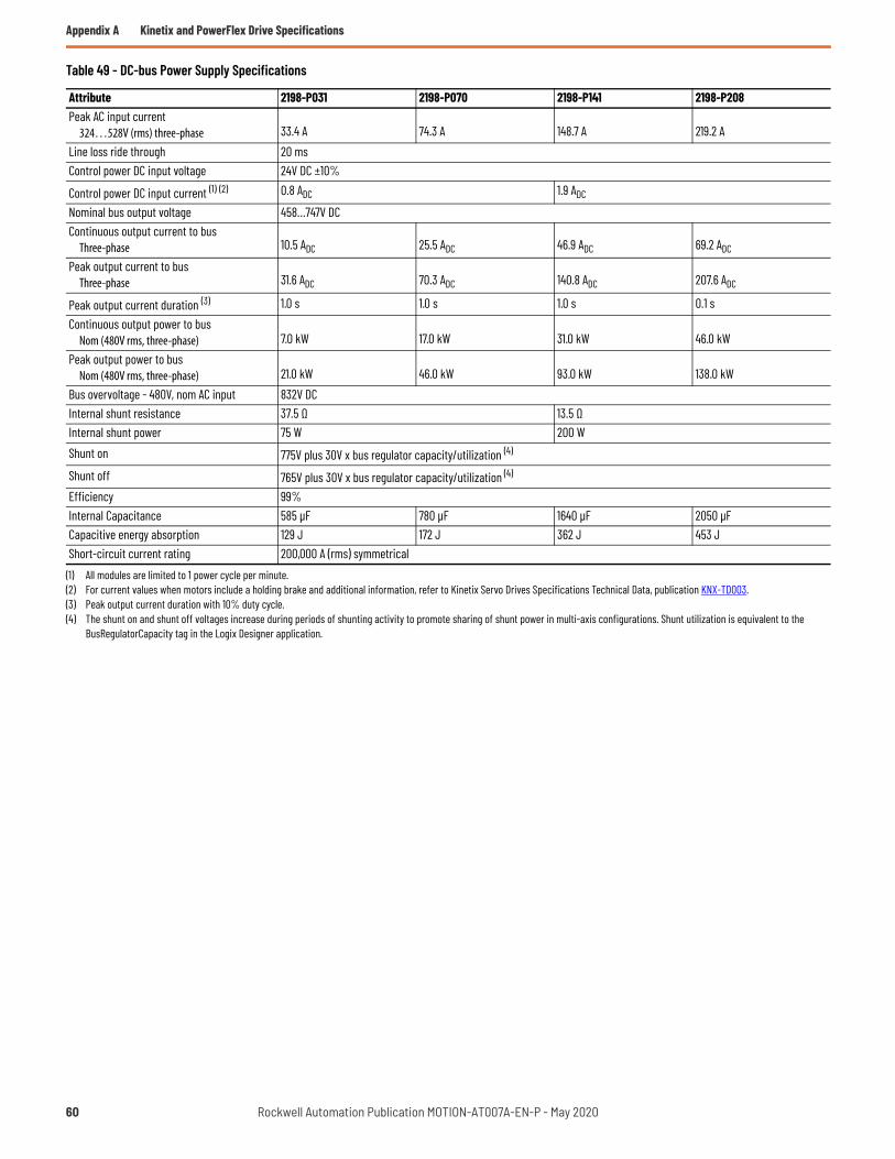
Appendix A Kinetix and PowerFlex Drive Specifications
Peak AC input current324…528V (rms) three-phase 33.4 A 74.3 A 148.7 A 219.2 A
Line loss ride through 20 msControl power DC input voltage 24V DC ±10%
Control power DC input current (1) (2) 0.8 ADC 1.9 ADC
Nominal bus output voltage 458…747V DCContinuous output current to bus
Three-phase 10.5 ADC 25.5 ADC 46.9 ADC 69.2 ADC
Peak output current to bus Three-phase 31.6 ADC 70.3 ADC 140.8 ADC 207.6 ADC
Peak output current duration (3) 1.0 s 1.0 s 1.0 s 0.1 sContinuous output power to bus
Nom (480V rms, three-phase) 7.0 kW 17.0 kW 31.0 kW 46.0 kWPeak output power to bus
Nom (480V rms, three-phase) 21.0 kW 46.0 kW 93.0 kW 138.0 kWBus overvoltage - 480V, nom AC input 832V DCInternal shunt resistance 37.5 Ω 13.5 ΩInternal shunt power 75 W 200 WShunt on 775V plus 30V x bus regulator capacity/utilization (4)
Shunt off 765V plus 30V x bus regulator capacity/utilization (4)
Efficiency 99%Internal Capacitance 585 µF 780 µF 1640 µF 2050 µFCapacitive energy absorption 129 J 172 J 362 J 453 JShort-circuit current rating 200,000 A (rms) symmetrical
(1) All modules are limited to 1 power cycle per minute. (2) For current values when motors include a holding brake and additional information, refer to Kinetix Servo Drives Specifications Technical Data, publication KNX-TD003.(3) Peak output current duration with 10% duty cycle.(4) The shunt on and shunt off voltages increase during periods of shunting activity to promote sharing of shunt power in multi-axis configurations. Shunt utilization is equivalent to the
BusRegulatorCapacity tag in the Logix Designer application.
Table 49 - DC-bus Power Supply Specifications
Attribute 2198-P031 2198-P070 2198-P141 2198-P208
60 Rockwell Automation Publication MOTION-AT007A-EN-P - May 2020

Kinetix and PowerFlex Drive Specifications Appendix A
Table 50 - Regenerative Bus Supply Specifications
Attribute 2198-RP088 2198-RP200 2198-RP263 2198-RP312
AC input voltage (1)
(1) Applies when DC-bus voltage regulation is enabled. If DC-bus voltage regulation is not enabled, the input voltage range is 324….528V AC. For more information on these two modes of operation, see the Kinetix 5700 Servo Drives User Manual, publication 2198-UM002.
324…506V rms, three-phase (480V nom)AC input frequency 47…63 Hz
Main AC input current (2)
324…506V (rms) three-phase
(2) All modules are limited to 1 power cycle per minute.
30.0 A 85.0 A 150.0 A 192.0 A
Max inrush (0-pk) 76.0 A 176.0 A 362.0 A 362.0 APeak AC input current
324…506V (rms) three-phase 75.0 A 170.0 A 225.0 A 288.9 ALine loss ride through 20 msControl power DC input voltage 24V DC ±10%
Control power DC input current (2) (3)
(3) For current values when motors include a holding brake and additional information, refer to Kinetix Servo Drives Specifications Technical Data, publication KNX-TD003.
4.3 ADC 5.4 ADC 9.1 ADC
Nominal bus output voltage 458…747V DCContinuous output current to bus 35.3 ADC 100.0 ADC 176.4 ADC 207.0 ADC
Peak output current to bus 88.0 ADC 200.0 ADC 263.0 ADC 312.0 ADC
Peak output current duration (4)
(4) 1.0 second peak output current duration with 10% duty cycle.3.0 second peak output current duration with 5% duty cycle.
1.0 s/3.0 sContinuous output power to bus
Nom (480V rms, three-phase) 24.0 kW 67.0 kW 119.0 kW 140.0 kWPeak output power to bus
Nom (480V rms, three-phase) 60.0 kW 135.8 kW 179.7 kW 211.4 kWBus overvoltage - 480V, nom AC input 832V DC
Internal shunt resistance (5)
(5) The 2198-RPxxx regenerative bus supply has no internal shunt resistor.
– –Efficiency 98%Internal Capacitance 940 µF 2460 µF 4510 µF 5740 µFCapacitive energy absorption 207 J 542 J 994 J 1265 JShort-circuit current rating 200,000 A (rms) symmetrical
Rockwell Automation Publication MOTION-AT007A-EN-P - May 2020 61

Appendix A Kinetix and PowerFlex Drive Specifications
Kinetix 6000 Drive Specifications
When using a non-Bulletin 2094 common-bus leader drive, DC-bus fuses are required in both lines of the DC-bus. For example, between the common-bus leader drive and follower IAM module. Base these fuse ratings on the DC output current of the common-bus leader drive. When using more than one follower IAM module, install fuses in both lines of the DC-bus. For example, between the non-Bulletin 2094 common-bus leader and the terminal block, and between the DC-bus terminal block and each follower IAM module.
The 2094-BCxx-Mxx-S and 2094-BMxx-S drive modules use internal solid-state motor short-circuit protection and, when protected by suitable branch circuit protection, are rated for use on a circuit capable of delivering up to 200,000 A (fuses) and 65,000 A (circuit breakers).
Table 51 - DC-bus Circuit-protection Specifications
IAM Module Cat. No.
DC-bus PowerBussmann Fuse Mersen Fuse (1)
(1) Mersen fuses were formerly known as Ferraz Shawmut.
2094-BC01-MP5-SFWJ-20A14F DCT20-2
2094-BC01-M01-S2094-BC02-M02-S FWJ-40A A70QS40-42094-BC04-M03-S FWJ-70A A70QS70-42094-BC07-M05-S FWJ-125A A70QS125-4
Table 52 - IAM Module (converter, 400V-class) Power Specifications (series A, B, and C)
Attribute 2094-BC01-MP5-S 2094-BC01-M01-S 2094-BC02-M02-S 2094-BC04-M03-S 2094-BC07-M05-SAC input voltage 324…528V rms three-phase (360…480V nom)DC input voltage (common bus follower) 458…747V DCDC input current (common-bus follower) 9.0 A 22.6 A 41.5 A 67.7 AContinuous power output to bus 6 kW 15 kW 27.6 kW 45 kWConverter capacitance 110 F 220 F 940 F 1410 F
Table 53 - AM Module (inverter, 400V-class) Power Specifications (series A, B, and C)
Attribute 2094-BMP5-M(2094-BC01-MP5-M)
2094-BM01-M(2094-BC01-M01-M)
2094-BM02-M(2094-BC02-M02-M)
2094-BM03-M(2094-BC04-M03-M)
2094-BM05-M(2094-BC07-M05-M)
Capacitance 75 F 150 F 270 F 840 F 1175 F
62 Rockwell Automation Publication MOTION-AT007A-EN-P - May 2020

Kinetix and PowerFlex Drive Specifications Appendix A
Kinetix 6200 and Kinetix 6500 Drive Specifications
When using a non-Bulletin 2094 common-bus leader drive, DC-bus fuses are required in both lines of the DC-bus. For example, between the common-bus leader drive and follower IAM module. Base these fuse ratings on the DC output current of the common-bus leader drive. When using more than one follower IAM module, install fuses in both lines of the DC-bus. For example, between the non-Bulletin 2094 common-bus leader and the terminal block, and between the DC-bus terminal block and each follower IAM module.
The 2094-BCxx-Mxx-M and 2094-BMxx-M drive modules use internal solid-state motor short-circuit protection and, when protected by suitable branch circuit protection, are rated for use on a circuit capable of delivering up to 200,000 A (fuses) and 65,000 A (circuit breakers).
Table 54 - DC-bus Circuit-protection Specifications
IAM Power Module Cat. No.
DC-bus PowerBussmann Fuse Mersen Fuse (1)
(1) Mersen fuses were formerly known as Ferraz Shawmut.
2094-BC01-MP5-MFWJ-20A14F DCT20-2
2094-BC01-M01-M2094-BC02-M02-M FWJ-40A A70QS40-42094-BC04-M03-M FWJ-70A A70QS70-42094-BC07-M05-M FWJ-125A A70QS125-4
Table 55 - IAM Module (converter, 400V-class) Power Specifications
Attribute 2094-BC01-MP5-M 2094-BC01-M01-M 2094-BC02-M02-M 2094-BC04-M03-M 2094-BC07-M05-MAC input voltage 324…528V rms three-phase (360…480V nom)DC input voltage (common bus follower) 458…747V DCDC input current (common-bus follower) 9.0 A 22.6 A 41.5 A 67.7 AContinuous power output to bus 6 kW 15 kW 27.6 kW 45 kWConverter capacitance 110 F 220 F 940 F 1410 F
Table 56 - AM Module (inverter, 400V-class) Power Specifications
Attribute 2094-BMP5-M(2094-BC01-MP5-M)
2094-BM01-M(2094-BC01-M01-M)
2094-BM02-M(2094-BC02-M02-M)
2094-BM03-M(2094-BC04-M03-M)
2094-BM05-M(2094-BC07-M05-M)
Capacitance 75 F 150 F 270 F 840 F 1175 F
Rockwell Automation Publication MOTION-AT007A-EN-P - May 2020 63

Appendix A Kinetix and PowerFlex Drive Specifications
Kinetix 7000 Drive Specifications
The following fuse examples and short-circuit current ratings are recommended for use with the 2099-BMxx-S drives when the line interface module (LIM) is not used.
Table 57 - Ferraz Shawmut Fuse Recommendations
Drive Cat. No. Drive Current Rating (ADC) Recommended Fuse Fuse Current
Rating
i²t (A²sec)Peak Let-through Current @ 100 kA rmsPre-arc Clearing @ 600V AC,
max2099-BM06-S 42.9 HSJ80 80 1600 15000 7000 A2099-BM07-S 55.7 HSJ90 90 2300 21000 7400 A2099-BM08-S 69.7 HSJ100 100 2700 23000 7700 A2099-BM09-S 105 HSJ175 175 8000 60000 12000 A2099-BM10-S 137 HSJ200 200 14000 92000 13000 A2099-BM11-S 204 HSJ400 400 63000 450000 21000 A2099-BM12-S 281 HSJ400 400 63000 450000 21000 A
Table 58 - Bussmann Fuse Recommendations
Drive Cat. No. Drive Current Rating (ADC) Recommended Fuse Fuse Current Rating
i²t (A²sec)Peak Let-through Current@ 100 kA rmsPre-arc Clearing @ 600V AC,
max2099-BM06-S 42.9 FWJ-80A 80 1550 9700 6300 A2099-BM07-S 55.7 FWJ-100A 100 2800 17500 8000 A2099-BM08-S 69.7 FWJ-125A 125 4800 35000 10000 A2099-BM09-S 105 FWJ-175A 175 7500 65000 12000 A2099-BM10-S 137 FWJ-200A 200 11700 80000 13000 A2099-BM11-S 204 FWJ-500A 500 39500 329000 21000 A2099-BM12-S 281 FWJ-500A 500 39500 329000 21000 A
Table 59 - Kinetix 7000 Drive Power Specifications
Attribute 2099-BM06-S 2099-BM07-S 2099-BM08-S 2099-BM09-S 2099-BM10-S 2099-BM11-S 2099-BM12-SAC input voltage 342…528V AC rms three-phase (380…480V nom)DC input voltage 450…750V DCDC input current 42.9 A 55.7 A 69.7 A 105 A 137 A 204 A 281 AContinuous power output, nom 22 kW 30 kW 37 kW 56 kW 75 kW 112 kW 149 kW
Total capacitance (1)
(1) If DC input is supplied to 2099-BM09-S, 2099-BM10-S, or 2099-BM11-S drives, the precharge capability must be provided at the system level. Disconnect switches must not be used between the input of the drive and a common DC-bus without the use of an external precharge device.
1800 F 2400 F 3000 F 4500 F 6000 F 8400 F 8400 FShort-circuit current rating 200,000 A (rms) symmetrical
64 Rockwell Automation Publication MOTION-AT007A-EN-P - May 2020

Kinetix and PowerFlex Drive Specifications Appendix A
PowerFlex 750-Series Drive Specifications
The following fuse examples are recommended for use with the 540V DC and 650V DC input PowerFlex 20F and 20G AC drives, Frame sizes 1…6.
Table 60 - 540V DC Input Fuses, Frames 1…6
Drive Cat. No. 20F and 20G (1)
Frame Size
kW Rating DC Input Rating Drive DC Bus Capacitance
Non-time Delay FuseQuantity
Amps Fuse Cat. No.ND HD Amps kW µF DC+ DC–
C2P1 10.75 – 2.1 1.1
110 1 16 Bussman JKS-6 (2)
– 0.37 1.3 0.7 4 Bussman JKS-4 (2)
C2P1 20.75 – 2.1 1.1
705 1 16 Bussman JKS-6 (2)
– 0.75 2.1 1.1 6 Bussman JKS-6 (2)
C3P5 11.5 – 3.7 2.0
165 1 18 Bussman JKS-8 (2)
– 0.75 2.1 1.1 6 Bussman JKS-6 (2)
C3P5 21.5 – 3.7 2.0
705 1 18 Bussman JKS-8 (2)
– 1.5 3.7 2.0 8 Bussman JKS-8 (2)
C5P0 12.2 – 5.3 2.9
280 1 110 Bussman JKS-10 (2)
– 1.5 3.7 2.0 8 Bussman JKS-8 (2)
C5P0 22.2 – 5.3 2.9
705 1 110 Bussman JKS-10 (2)
– 2.2 5.3 2.9 10 Bussman JKS-10 (2)
C8P7 14 – 9.3 5.0
470 1 115 Mersen HSJ15 (3)
– 2.2 5.3 2.9 10 Mersen HSJ10 (3)
C8P7 24 – 9.3 5.0
705 1 115 Mersen HSJ15 (3)
– 4 9.3 5.0 15 Mersen HSJ15 (3)
C011 15.5 – 12.6 6.8
560 1 120 Mersen HSJ20 (3)
– 4 9.3 5.0 15 Mersen HSJ15 (3)
C011 25.5 – 12.6 6.8
705 1 120 Mersen HSJ20 (3)
– 5.5 12.6 6.8 20 Mersen HSJ20 (3)
C015 17.5 – 17.0 9.2
680 1 125 Mersen HSJ25 (3)
– 5.5 12.6 6.8 20 Mersen HSJ20 (3)
C015 27.5 – 17.0 9.2
705 1 125 Mersen HSJ25 (3)
– 5.5 12.6 6.8 20 Mersen HSJ20 (3)
C022 211 – 24.6 13.3
1020 1 140 Mersen HSJ40 (3)
– 7.5 17.0 9.2 25 Mersen HSJ25 (3)
C030 315 – 33.6 18.1
1200 1 150 Mersen HSJ50 (3)
– 11 24.6 13.3 40 Mersen HSJ40 (3)
C037 318.5 – 41.4 22.3
1500 1 170 Mersen HSJ70 (3)
– 15 33.6 18.1 50 Mersen HSJ50 (3)
C043 322 – 48.1 26.0
1800 1 190 Mersen HSJ90 (3)
– 18.5 41.4 22.3 70 Mersen HSJ70 (3)
C060 430 – 67.1 36.2
2400 1 1100 Mersen HSJ100 (3)
– 22 48.1 26.0 90 Mersen HSJ90 (3)
C072 437 – 82.4 44.5
3000 1 1125 Mersen HSJ125 (3)
– 30 67.1 36.2 100 Mersen HSJ100 (3)
C072 537 – 82.4 44.5
3600 1 1125 Mersen HSJ125 (3)
– 30 67.1 36.2 100 Mersen HSJ100 (3)
C085 545 – 97.3 52.5
3600 1 1150 Mersen HSJ150 (3)
– 37 82.4 44.5 125 Mersen HSJ125 (3)
Rockwell Automation Publication MOTION-AT007A-EN-P - May 2020 65

Appendix A Kinetix and PowerFlex Drive Specifications
C104 555 – 120.2 64.9
4500 1 1175 Mersen HSJ175 (3)
– 45 97.3 52.5 150 Mersen HSJ150 (3)
C104 655 – 120.2 64.9
4600 1 1175 Mersen HSJ175 (3)
– 45 97.3 52.5 150 Mersen HSJ150 (3)
C140 675 – 160.3 86.5
4600 1 1250 Mersen HSJ250 (3)
– 55 120.2 64.9 175 Mersen HSJ175 (3)
C170 690 – 194.6 105.1
9200 1 1350 Mersen HSJ350 (3)
– 75 160.3 86.5 250 Mersen HSJ250 (3)
C205 6110 – 234.7 126.7
9200 1 1350 Mersen HSJ350 (3)
– 90 194.6 105.1 350 Mersen HSJ350 (3)
C260 6132 – 297.7 160.7
9200 1 1450 Mersen HSJ450 (3)
– 110 234.7 126.7 350 Mersen HSJ350 (3)
(1) Drive input type (position 5 of catalog number) = 1 (AC input with precharge, includes DC terminals) or 4 (DC input with precharge).(2) See Fuse Certification and Test Data on page 68 for fuse self-certification and test data for Bussmann 170M and JKS fuses that are recommended for the DC-bus fusing.(3) A test program was developed to confirm that the HSJ (High Speed J) fuses meet or exceed the requirements set forth by Rockwell Automation for the fuses on the common DC-bus for all
Allen-Bradley® architecture, component, and legacy drives. The criteria for acceptance was:• 600V AC rectified, 810V DC average, fuses located at (+) and (-) leg. Short circuit test at 65 kA.• Time constant minimum 3 milliseconds (maximum 15 milliseconds).• No over-load protection required.• Let-through must be less than rating of the conductors.This testing is listed in UL file E2137 Vol2 Sec 31 page 1 and in CSA report 1662646.
Table 61 - 650V DC Input Fuses, Frames 1…6
Drive Cat. No. 20F and 20G (1)
Frame Size
HP Rating DC Input Rating Drive DC Bus Capacitance
Non-time Delay Fuse
ND HD Amps kW Amps Fuse Cat. No.Quantity
µF DC+ DC–
D2P1 11 – 1.9 1.2
1106 Bussman JKS-6 (2)
1 1– 0.5 1.1 0.72 4 Bussman JKS-4 (2)
D2P1 21 – 1.9 1.2
7056 Bussman JKS-6 (2)
1 1– 1 1.9 1.2 6 Bussman JKS-6 (2)
D3P4 12 – 3.0 2.0
1656 Bussman JKS-6 (2)
1 1– 1 1.9 1.2 6 Bussman JKS-6 (2)
D3P4 22 – 3.0 2.0
7056 Bussman JKS-6 (2)
1 1– 2 3.0 2.0 6 Bussman JKS-6 (2)
D5P0 13 – 4.5 2.9
28010 Bussman JKS-10 (2)
1 1– 2 3.0 2.0 6 Bussman JKS-6 (2)
D5P0 23 – 4.5 2.9
70510 Bussman JKS-10 (2)
1 1– 3 4.5 2.9 10 Bussman JKS-10 (2)
D8P0 15 – 8.1 5.3
47015 Mersen HSJ15 (3)
1 1– 3 4.5 2.9 10 Bussman JKS-10 (2)
D011 17.5 – 11.1 7.2
56020 Mersen HSJ20 (3)
1 1– 5 8.1 5.3 15 Mersen HSJ15 (3)
D011 27.5 – 11.1 7.2
70520 Mersen HSJ20 (3)
1 1– 7.5 11.1 7.2 20 Mersen HSJ20 (3)
D014 110 – 14.7 9.6
68030 Mersen HSJ30 (3)
1 1– 7.5 11.1 7.2 20 Mersen HSJ20 (3)
D014 210 – 14.7 9.5
70530 Mersen HSJ30 (3)
1 1– 7.5 11.1 7.2 20 Mersen HSJ20 (3)
Table 60 - 540V DC Input Fuses, Frames 1…6 (continued)
Drive Cat. No. 20F and 20G (1)
Frame Size
kW Rating DC Input Rating Drive DC Bus Capacitance
Non-time Delay FuseQuantity
Amps Fuse Cat. No.ND HD Amps kW µF DC+ DC–
66 Rockwell Automation Publication MOTION-AT007A-EN-P - May 2020

Kinetix and PowerFlex Drive Specifications Appendix A
D022 215 – 23.3 15.1
102040 Mersen HSJ40 (3)
1 1– 10 14.7 9.5 30 Mersen HSJ30 (3)
D027 320 – 28.9 18.8
120050 Mersen HSJ50 (3)
1 1– 15 23.3 15.1 40 Mersen HSJ40 (3)
D034 325 – 36.4 23.6
150060 Mersen HSJ60 (3)
1 1– 20 28.9 18.8 50 Mersen HSJ50 (3)
D040 330 – 42.9 27.8
180080 Mersen HSJ80 (3)
1 1– 25 36.4 23.6 60 Mersen HSJ60 (3)
D052 440 – 55.7 36.1
240090 Mersen HSJ90 (3)
1 1– 30 42.9 27.8 80 Mersen HSJ80 (3)
D065 450 – 69.7 45.1
3000100 Mersen HSJ100 (3)
1 1– 40 55.7 36.1 90 Mersen HSJ90 (3)
D065 550 – 69.7 45.3
3600100 Mersen HSJ100 (3)
1 1– 40 55.7 36.2 90 Mersen HSJ90 (3)
D077 560 – 84.5 54.7
3600150 Mersen HSJ150 (3)
1 1– 50 69.7 45.1 100 Mersen HSJ100 (3)
D096 575 – 105.3 68.3
4500175 Mersen HSJ175 (3)
1 1– 60 84.5 54.7 150 Mersen HSJ150 (3)
D096 675 – 105.3 68.4
4600175 Mersen HSJ175 (3)
1 1– 60 84.5 54.9 150 Mersen HSJ150 (3)
D125 6100 – 137.1 88.9
4600200 Mersen HSJ200 (3)
1 1– 75 105.3 68.3 175 Mersen HSJ175 (3)
D156 6125 – 171.2 110.9
9200300 Mersen HSJ300 (3)
1 1– 100 137.1 88.9 200 Mersen HSJ200 (3)
D186 6150 – 204.1 132.2
9200400 Mersen HSJ400 (3)
1 1– 125 171.2 110.9 300 Mersen HSJ300 (3)
D248 6200 – 272.1 176.3
9200400 Mersen HSJ400 (3)
1 1– 150 204.1 132.2 400 Mersen HSJ400 (3)
(1) Drive input type (position 5 of catalog number) = 1 (AC input with precharge, includes DC terminals) or 4 (DC input with precharge).(2) See Fuse Certification and Test Data on page 68 for fuse self-certification and test data for Bussmann 170M and JKS fuses that are recommended for the DC-bus fusing.(3) A test program was developed to confirm that the HSJ (High Speed J) fuses meet or exceed the requirements set forth by Rockwell Automation for the fuses on the common DC-bus for all
Allen-Bradley architecture, component, and legacy drives. The criteria for acceptance was:• 600V AC rectified, 810V DC average, fuses located at (+) and (-) leg. Short circuit test at 65 kA.• Time constant minimum 3 milliseconds (maximum 15 milliseconds).• No over-load protection required.• Let-through must be less than rating of the conductors.This testing is listed in UL file E2137 Vol2 Sec 31 page 1 and in CSA report 1662646.
Table 61 - 650V DC Input Fuses, Frames 1…6 (continued)
Drive Cat. No. 20F and 20G (1)
Frame Size
HP Rating DC Input Rating Drive DC Bus Capacitance
Non-time Delay Fuse
ND HD Amps kW Amps Fuse Cat. No.Quantity
µF DC+ DC–
Rockwell Automation Publication MOTION-AT007A-EN-P - May 2020 67

Appendix A Kinetix and PowerFlex Drive Specifications
Fuse Certification and Test Data
The following are copies of self-certification letters and test data for JKS and 170M fuses that are recommended in the previous tables for PowerFlex 750-Series drives (Frames 1…6). Configuration A indicates one fuse in the (+) leg and one fuse in the (–) leg of the DC-bus.
JKS Fuses
Cooper BussmannP. O. Box 14460St. Louis, MO 63178-4460
January 25, 2002
Sr. Project Engineer, Rockwell Automation6400 West Enterprise DriveP.O. Box 760Mequon, WI 53092
Subject: DC Testing for JKS Fuses
Dear Mr.
At the request of Rockwell Automation, Bussmann has completed the DC testing for the JKS fuses and is pleased to present the attached information indicating successful 'Self-Certification DC Rating' on all subject fuses. Bussmann tested fuses to the following parameters specified by Rockwell Automation:
• Short Circuit Current = 65 kA• Voltage = 810V DC• Time Constant ≥0.4 ms
Additional tests were performed for acceptability:• Short Circuit Current = 30 times fuse amperage• Voltage = 810V DC• Time Constant ≥0.4 ms
The attached table identifies the fuses tested, the actual circuit parameters and the circuit configuration. In the attached table, the Interrupting Amps column specifies the fuses minimum and maximum amps that the fuse will safely clear at 810V DC.
By way of this correspondence, Cooper Bussmann self-certifies the preceding fuses in end-user applications to the preceding parameters and the attached data sheet.
Should you have any questions regarding this correspondence, please contact me at the listed address and numbers.
Regards,Strategic OEM Accounts ManagerCooper Bussmann
Circuit Configuration A
Fuse Fuse
68 Rockwell Automation Publication MOTION-AT007A-EN-P - May 2020

Kinetix and PowerFlex Drive Specifications Appendix A
170M Fuses
Cooper BussmannP. O. Box 14460St. Louis, MO 63178-4460
May 15, 2002
Sr. Project Engineer, Rockwell Automation6400 West Enterprise DriveP.O. Box 760Mequon, WI 53092
Subject: DC Testing for 170M Fuses
Dear Mr.
At the request of Rockwell Automation, Bussmann has completed the DC testing for the 170M fuses and is pleased to present the attached information indicating successful 'Self-Certification DC Rating' on all subject fuses.
Bussmann tested fuses to the following parameters specified by Rockwell Automation:• Short Circuit Current = 65 kA and 100 kA• Voltage = 810V DC• Time Constant ≥0.4 ms
Additional tests were performed for acceptability:• Short Circuit Current = 30 times fuse amperage as minimum current interrupting rating or as tested• Voltage = 810V DC• Time Constant ≥0.4 ms
Table 62 - Cooper Bussmann JKS, DC Fuse Test for Rockwell Automation
Fuse ResultsCircuit Parameters
Interrupting AmpsVolts DC Time Constant Circuit Configuration
Min MaxJKS-(3A…15A) Acceptable – 69.6 kA 810 2.78 ms Configuration AJKS-(3A…15A) Acceptable 375 A – 810 0.55 ms Configuration AJKS-(20A…30A) Acceptable – 69.6 kA 816 2.78 ms Configuration AJKS-(20A…30A) Acceptable 920 A – 812 0.4 ms Configuration AJKS-(35A…60A) Acceptable – 69.6 kA 816 2.78 ms Configuration AJKS-(35A…60A) Acceptable 1820 A – 812 0.5 ms Configuration AJKS-(70A…100A) Acceptable – 69.6 kA 816 2.78 ms Configuration AJKS-(70A…100A) Acceptable 2950 A – 812 0.86 ms Configuration AJKS-(110A…200A) Acceptable – 69.6 kA 816 2.78 ms Configuration AJKS-(110A…200A) Acceptable 5960 A – 810 3.34 ms Configuration AJKS-(225A…400A) Acceptable – 69.6 kA 816 2.78 ms Configuration AJKS-(225A…400A) Acceptable 11.5 kA – 812 2.92 ms Configuration AJKS-(450A…600A) Acceptable – 69.6 kA 816 2.78 ms Configuration AJKS-(450A…600A) Acceptable 15.5 kA – 810 0.4 ms Configuration A
Rockwell Automation Publication MOTION-AT007A-EN-P - May 2020 69

Appendix A Kinetix and PowerFlex Drive Specifications
The attached table identifies the fuses tested, the actual circuit parameters and the circuit configuration. In the attached table, the Interrupting Amps column specifies the fuses minimum and maximum amps that the fuse will safely clear at 810V DC.
By way of this correspondence, Cooper Bussmann self-certifies the preceding fuses in end-user applications to the preceding parameters and the attached data sheet.
Should you have any questions regarding this correspondence, please contact me at the listed address and numbers.
Regards,Strategic OEM Accounts ManagerCooper Bussmann
Table 63 - Cooper Bussmann 170M, DC Fuse Test for Rockwell Automation
Fuse ResultsCircuit ParametersInterrupting Amps
Volts DC Time Constant Circuit ConfigurationMin Max
170M6646 Acceptable – 69.8 kA 812 2 ms Configuration A170M6646 Acceptable 10.2 kA – 812 1.66 ms Configuration A170M6650 Acceptable – 69.6 kA 812 2 ms Configuration A170M6650 Acceptable 21.1 kA – 812 1.2 ms Configuration A170M7510 – – 65 kA 810 2 ms –170M7510 – 20 kA – 810 2 ms –170M6792 – – 65 kA 810 2 ms –170M6792 – 19 kA – 810 2 ms –170M6793 – – 65 kA 810 2 ms –170M6793 – 23 kA – 810 2 ms –170M6794 – – 65 kA 810 2 ms –170M6794 – 27.5 kA – 810 2 ms –170M6828 – – 65 kA 810 2 ms –170M6828 – 37 kA – 810 2 ms –170M6934 Acceptable – 105.4 kA 810 1.8 ms Configuration A170M6934 Acceptable 45.2 kA – 810 1.12 ms Configuration A170M7560 – – 100 kA 810 2 ms –170M7560 – 60 kA – 810 2 ms –
Circuit Configuration A
Fuse Fuse
70 Rockwell Automation Publication MOTION-AT007A-EN-P - May 2020

Appendix B
Kinetix 5700 Accessory Modules
The requirements for when to use accessory modules vary depending on whether your system is powered by the 2198-Pxxx DC-bus power supply or 2198-RPxxx regenerative bus supply.
Accessory Flow Chart
In this flowchart, a 2198-Pxxx DC-bus power supply or 2198-RPxxx regenerative bus supply supplies DC-bus power to a mixed-architecture common-bus drive system.
System variables that you need to know include the following:• The type of AC to DC converter used• The external DC-bus current
Accessory ModuleCat. No. Accessory Module Description
2198-CAPMOD-2240 Capacitor ModuleUse for energy storage and to extend the DC-bus voltage to another inverter cluster. Modules are zero-stacked with servo drives and use the shared-bus connection system to extend the external DC-bus voltage in applications up to 104 A. Can parallel with itself or with another accessory module for up to 208 A.
2198-CAPMOD-DCBUS-IO Extension Module The extension module, paired with a capacitor module or DC-bus conditioner module, is used to extend the DC-bus voltage to another inverter cluster in systems with ≥104 A current and up to 208 A.
2198-DCBUSCOND-RP312 DC-bus Conditioner ModuleDecreases the voltage stress on insulation components in an inverter system with long cable lengths and used to extend the DC-bus voltage to another inverter cluster. Modules are zero-stacked with servo drives and use the shared-bus connection system to extend the external DC-bus voltage in applications up to 104 A. Can parallel with itself or with another accessory module for applications up to 208 A.
The power supply cluster includes the 2198-Pxxx DC-bus power supply or 2198-RPxxx regenerative bus supply.
Rockwell Automation Publication MOTION-AT007A-EN-P - May 2020 71

Appendix B Kinetix 5700 Accessory Modules
Figure 39 - Mixed Architecture Common-bus System
Capacitor Module
The capacitor module is used for energy storage and to extend the DC-bus voltage to another inverter cluster. Modules are zero-stacked with servo drives and use the shared-bus connection system to extend the external DC-bus voltage in applications up to 104 A. The module can be paralleled with itself or with another accessory module for up to 208 A.
Observe the following capacitor module guidelines:• Required in each cluster of a multi-cluster system• More than one capacitor module can be used in a cluster, if needed• Flexible bus-bars are included with only the 2198-CAPMOD-DCBUS-IO extension module. So, if you have two capacitor modules, two DC-
bus conditioner modules, or a capacitor module and DC-bus conditioner module mounted side by side, you must order the 2198-KITCON-CAPMOD2240 or 2198-KITCON-DCBUSCOND connector set separately.
<104 A
What type of AC to DCconverter is used?
Start
What is theexternal DC-bus
current?
Kinetix 5700DC-bus Power Supply
Kinetix 5700Regenerative Bus Supply
Yes
No
Power Supply Cluster:• Capacitor Module
Power Supply Cluster:• Capacitor Module• Extension Module
Is there anexternal active shunt
in the system?
≥104 Aup to 208 A, max
Power Supply Cluster:• Capacitor Module• DC-bus Conditioner Module
Power Supply Cluster:• Capacitor Module• DC-bus Conditioner Module
72 Rockwell Automation Publication MOTION-AT007A-EN-P - May 2020

Kinetix 5700 Accessory Modules Appendix B
Figure 40 - Capacitor Module Block Diagram
You can configure either of the DC-bus power supply digital inputs as Bus Capacitor OK in the Logix Designer application to monitor the Module Status output. Refer to the Kinetix® 5700 Servo Drives User Manual, publication 2198-UM002, to see how the DC-bus power supply Digital Inputs category is configured.
Figure 41 - DC-bus Power Supply with Capacitor Module
(1) Configure either of two digital inputs as Bus Capacitor OK. For DC-bus power supply configurable functions, see Kinetix 5700 Servo Drives User Manual, publication 2198-UM002.
Refer to the Kinetix 5700 Servo Drives User Manual, publication 2198-UM002, for more information on accessory module installation.
DC–
DC+
DC+
DC–
DC–
DC+
DC–
MS
MS
DC-bus InputLink Connector
DC-bus OutputLug Connector
Module StatusStatus Indicator
DC-bus StatusStatus Indicator
Module Status(MS) Connector
Fuse Detection
DC-bus Detection
Capacitor Bank
BleederResistor
Fuse
(1)
24V DC
MS
MS
INx
COM
2198-Pxxx DC-bus Power Supply
2198-CAPMOD-2240Capacitor Module
Module Status (MS) Connector
Digital Input(IOD) Connector
Rockwell Automation Publication MOTION-AT007A-EN-P - May 2020 73

Appendix B Kinetix 5700 Accessory Modules
DC-Bus Conditioner Module
The DC-bus conditioner module decreases the voltage stress on insulation components in an inverter system with long cable lengths and can be used to extend the DC-bus voltage to another inverter cluster. Modules are zero-stacked with servo drives and use the shared-bus connection system to extend the external DC-bus voltage in applications up to 104 A. The module can be paralleled with itself or with another accessory module for applications up to 208 A.
Observe the following DC-bus conditioner module guidelines:• A DC-bus conditioner module is required on all Kinetix 5700 extended clusters• A DC-bus conditioner module is required on the power supply cluster if a regenerative bus supply or external active shunt is included
in the system.• When a DC-bus conditioner module is installed and there is no use-case for installation, the module does not provide any benefit• Flexible bus-bars are included with only the 2198-CAPMOD-DCBUS-IO extension module. So, if you have two capacitor modules, two
DC-bus conditioner modules, or a capacitor module and DC-bus conditioner module mounted side by side, you must order the2198-KITCON-CAPMOD2240 or 2198-KITCON-DCBUSCOND connector set separately.
Figure 42 - DC-bus Conditioner Module Block Diagram
You can configure any of the regenerative bus supply digital inputs as Bus Conditioner OK in the Logix Designer application to monitor the Module Status output. Refer to Kinetix 5700 Servo Drives User Manual, publication 2198-UM002, to see how the regenerative bus supply Digital Inputs category is configured.
DC+
DC–
DC+
DC–
MS
MS
Chassis
DC-bus InputLink Connector
DC-bus OutputLug Connector
Module StatusStatus Indicator
DC-bus StatusStatus Indicator
Module Status(MS) Connector
Fuse Detection and Over Temperature
Protection
DC-bus Detection
Fuse Conditioning Circuit
74 Rockwell Automation Publication MOTION-AT007A-EN-P - May 2020

Kinetix 5700 Accessory Modules Appendix B
Figure 43 - Regenerative Bus Supply with DC-bus Conditioner Module
(1) Configure any one of four digital inputs as Bus Conditioner OK. For regenerative bus supply configurable functions, see Kinetix 5700 Servo Drives User Manual, publication 2198-UM002.
Refer to the Kinetix 5700 DC-bus Conditioner Module Installation Instructions, publication 2198-IN016, for additional installation information.
Extension Module
The extension module, when paired with a capacitor module, is used to extend the DC-bus voltage to another inverter cluster in systems with ≥104 A current and up to 208 A.
Observe the following extension module guidelines:• The extension module is always mounted next to a capacitor module or DC-bus conditioner module and always positioned on the
outside of the system cluster (either first or last).• Flexible bus-bars are included with the 2198-CAPMOD-DCBUS-IO extension module. So, if you have a 2198-CAPMOD-DCBUS-IO extension
module with a capacitor module or a DC-bus conditioner module, you do not need to order the 2198-KITCON-CAPMOD2240 or 2198-KITCON-DCBUSCOND connector set separately.
(1)
24V DCINx
COM
MS
MS
2198-RPxxx Regenerative Bus Supply
2198-DCBUSCOND-RP312 DC-bus Conditioner Module
Module Status (MS) Connector
Digital Input(IOD) Connector
Rockwell Automation Publication MOTION-AT007A-EN-P - May 2020 75

Appendix B Kinetix 5700 Accessory Modules
Notes:
76 Rockwell Automation Publication MOTION-AT007A-EN-P - May 2020

Index
Numerics2094 shunt module
2094-BSP2 19, 28, 38, 482198-CAPMOD-2240 8, 10, 11, 712198-CAPMOD-DCBUS-IO 10, 712198-DCBUSCOND-RP312 8, 11, 71
AAC line impedance 19, 28, 39, 49accessory modules 33, 54
capacitor module 71, 72DC-bus conditioner module 71, 74extension module 71, 75flow chart 71
active shuntinterconnect diagram 33, 54lug connections 33, 54Shunt Thermal Switch OK 31, 52specifications 31, 52use cases 31, 52
active-front-end 7
Bblock diagrams
capacitor module 73DC-bus conditioner module 74
braking chopper 15, 25Bus Capacitor OK 10bus overvoltage faults 8Bus Voltage Reference Source 8Bus Voltage Set Point 8
Ccable length 8, 10capacitance 59capacitance sizing 24, 36, 44, 58capacitor module 71, 72, 73circuit protection 24, 36, 44, 58
Kinetix 6000 62Kinetix 6200/6500 63Kinetix 7000 64PowerFlex 750-Series 65
cluster example 11common bus 8contactor enable 35, 43, 57contactor enable control string 23, 35, 43, 57contactor-enable relay circuit 23, 35converter OK 42, 56
Kinetix 6000 42, 56Kinetix 6200/6500 42, 56Kinetix 7000 42, 56PowerFlex 750-Series 42, 56
DDC bus bar 10
cable length 10example 11
DC-buscable gauge 9cables 8
cable length 8low inductance 9
capacitance 24, 36, 44, 58, 59conditioner module 71, 74connections 8, 10
Bus Capacitor OK 10DC bus bar 10DC-bus cable gauge 9DC-bus cables 8wiring 9, 10
current 10filter 11link 9lug connections 33, 54wiring example 10
digital inputprecharge enable 12
diode-front-end 7, 17, 25disconnect switch 20, 29, 39, 49drive system
DC-bus connections 8extended bus example 8mounting order 7
EEnable 42, 56extension module 71, 75external active shunt 47, 48external passive shunt 46
Fflexible bus-bars 33, 54flow chart 71full regeneration 37fuse certification and test data 68
Gground jumper settings 21, 30, 40, 51, 55ground screw settings 22, 34, 41
IIEEE-519 37, 45interconnect diagrams
active shunt 33, 54module status 73, 75
internalIGBT 19, 28, 38, 48shunt 15, 25
Rockwell Automation Publication MOTION-AT007A-EN-P - May 2020 77

Index
KKinetix 5700 10
cluster example 11DC-bus connections 10DC-bus link 9DC-bus supply 17, 25DC-bus wiring example 10regenerative bus supply 37, 45specifications 59
Kinetix 6000circuit protection specifications 62drives 8, 15ground jumper settings 21, 30, 40, 51power specifications, AM 460V 62power specifications, IAM 460V 62specifications 62
Kinetix 6200/6500 63circuit protection specifications 63drives 15specifications
power, AM 460V 63power, IAM 460V 63
Kinetix 7000circuit protection specifications 64drives 8, 14ground jumper settings 21, 30, 40, 51I/O connections 20, 29, 40, 50Relay connections 20, 29, 40, 50specifications 64
Lline reactor 18, 26, 27, 38, 39, 46, 47, 48, 49
Mmaximum cable lengths 24, 36, 44, 58module status 10
DC-bus power supply 73regenerative bus supply 75
Motion Analyzer website 81mounting order 7
Nnon-regenerative
definition 7
non-regenerative bus supplyAC line impedance 19, 28active shunt specifications 31capacitance sizing 24, 36circuit protection 24, 36configurations 18, 26contactor enable 23, 35contactor-enable relay circuit 23, 35DC-bus capacitance 24, 36disconnect switch 20, 29ground jumper settings 21, 30ground screw settings 22, 34Kinetix 5700 DC-bus supply 17, 25Kinetix 7000 I/O connections 20, 29line reactor 18, 26, 27maximum cable lengths 24, 36passive shunt connections 32passive shunt specifications 32Precharge Enable 20, 29system sizing 24, 36total system capacitance 24, 36
Ppassive shunt
connections 32specifications 32
PowerFlex 750-SeriesAC Drive 8circuit protection specifications 65frames 1…4 12frames 5 and 6 13ground jumper settings 21, 30, 41, 51precharge parameters 20, 29, 39, 49
precharge 42, 56DC-bus filter 11enable 12Kinetix 6000 drives 15Kinetix 6200/6500 drives 15Kinetix 7000 drives 14parameters 20, 29, 39, 49PowerFlex 750-Series, frames 1…4 12PowerFlex 750-Series, frames 5 and 6 13
Precharge Enable 20, 29, 39, 49
RRegen OK 42, 56Regeneration OK 42, 56regeneration plus shunt 45regenerative
definition 7
78 Rockwell Automation Publication MOTION-AT007A-EN-P - May 2020

Index
regenerative bus supplyAC line impedance 39, 49active shunt specifications 52bus overvoltage fault 8bus voltage set point 8capacitance sizing 44, 58circuit protection 44, 58configurations 38, 46contactor enable 43, 57converter OK 42, 56DC-bus capacitance 44, 58disconnect switch 39, 49external active shunt 47, 48external passive shunt 46full regeneration 37ground jumper settings 40, 51, 55ground screw settings 41Kinetix 5700 regenerative bus supply 37, 45Kinetix 7000 I/O connections 40, 50line reactor 38, 39, 46, 47, 48, 49maximum cable lengths 44, 58meets IEEE-519 37, 45Precharge Enable 39, 49regeneration plus shunt 45shunt connections 53system sizing 44, 58total system capacitance 44, 58
Sshunt
active 31, 52connections 53resister 15, 25
Shunt Thermal Switch OK 31, 33, 52, 54sizing 24, 36, 44, 58specifications
DC-bus capacitance 59fuse certification and test data 68Kinetix 5700 59
capacitance 59DC-bus power supply 59regenerative bus supply 61
Kinetix 6000 62circuit protection 62
Kinetix 6000 power specificationsAM 460V 62IAM 460V 62
Kinetix 6200/6500 63circuit protection 63power, AM 460V 63power, IAM 460V 63
Kinetix 7000circuit protection 64specifications 64
PowerFlex 750-Seriescircuit protection 65
systemsizing 24, 36, 44, 58
system block diagramscapacitor module 73DC-bus conditioner module 74
Ttotal system capacitance 24, 36, 44, 58
Uuse cases
active shunt 31, 52
Wwebsite
Motion Analyzer 81wiring
external DC-bus 9, 10
Rockwell Automation Publication MOTION-AT007A-EN-P - May 2020 79

Index
Notes:
80 Rockwell Automation Publication MOTION-AT007A-EN-P - May 2020

Rockwell Automation Publication MOTION-AT007A-EN-P - May 2020 81
Drives in Common Bus Configurations with Kinetix 5700 Bus Supplies Application Technique
Additional ResourcesThese documents contain additional information concerning related products from Rockwell Automation.
You can view or download publications at rok.auto/literature.
Resource Description
Kinetix Rotary Motion Specifications Technical Data, publication KNX-TD001 Provides product specifications for Kinetix VPL, VPC, VPF, VPH, and VPS motors, Kinetix MPL, MPM, MPF, and MPS motors, and Kinetix HPK rotary motors.
Kinetix Linear Motion Specifications Technical Data, publication KNX-TD002Provides product specifications for Kinetix MPAS and MPMA linear stages,Kinetix VPAR, MPAR, and MPAI electric cylinders, LDAT-Series linear thrusters, andLDC-Series™ linear motors.
Kinetix Servo Drives Specifications Technical Data, publication KNX-TD003Provides product specifications for Kinetix Integrated Motion over the EtherNet/IP™ network, Integrated Motion over Sercos interface, EtherNet/IP networking, and component servo drive families.
Kinetix Motion Accessories Specifications Technical Data, publication KNX-TD004
Provides product specifications for 2090-Series motor and interface cables, low-profile connector kits, drive power components, and other servo drive accessory items.
Kinetix 5700 Servo Drives User Manual, publication 2198-UM002
Provides information on installing, configuring, startup, troubleshooting, and applications for your Kinetix servo drive system.
Kinetix 6000 Multi-axis Servo Drives User Manual, publication 2094-UM001Kinetix 6200 and Kinetix 6500 Modular Multi-axis Servo Drives User Manual, publication 2094-UM002Kinetix 7000 High Power Servo Drives User Manual, publication 2099-UM001
Kinetix Motion Control Selection Guide, publication KNX-SG001Overview of Kinetix servo drives, motors, actuators, and motion accessories designed to help make initial decisions for the motion control products best suited for your system requirements.
Kinetix 5700 Drive Systems Design Guide, publication KNX-RM010System design guide to select the required (drive specific) drive module, power accessory, feedback connector kit, and motor cable catalog numbers for your Kinetix drive system.
Kinetix 6000 and Kinetix 6200/6500 Drive Systems Design Guide,publication KNX-RM003Kinetix 7000 Drive Systems Design Guide, publication GMC-RM007PowerFlex 750-Series Drive Technical Data, publication 750-TD001 Provides technical data on PowerFlex 750-Series drives.PowerFlex 750-Series Products with TotalFORCE® Control Technical Data, publication 750-TD100
Provides detailed information on, kit selection, kit ratings and specifications, and option specifications.
1321 Power Conditioning Products Technical Data, publication 1321-TD001 Information on line reactors and isolation transformers.Drives in Common Bus Configurations Application Technique, publication DRIVES-AT002
Provides the necessary guidelines, considerations, and limitations for the proper application of PowerFlex drives used in common bus configurations.
Drives in Common Bus Configurations with PowerFlex 755TM Bus Supplies Application Technique, publication DRIVES-AT005
Provides the necessary guidelines, considerations, and limitations for the proper application of Allen-Bradley drives used in common bus configurations.
Industry Installation Guidelines for Pulse Width Modulated (PWM) AC Drives,publication DRIVES-AT003
Provides basic information for different enclosure systems, environmental/location considerations, and power and grounding considerations needed to properly install a Pulse Width Modulated (PWM) AC drive.
Wiring and Grounding Guidelines for Pulse Width Modulated (PWM) AC Drives, publication DRIVES-IN001
Provides basic information to install, protect, wire, and ground pulse width modulated (PWM) AC drives.
PowerFlex 750-Series AC Drives Installation Instructions, publication 750-IN001 Provides the basic steps to install PowerFlex 750-Series drives. PowerFlex 750-Series Power Jumpers Installation Instructions, publication 750-IN011 Provides jumper settings for PowerFlex 750-Series AC drives.
PowerFlex 750-Series EMC Plate and Cores - Frames 1…7 Installation Instructions, publication 750-IN006 Provides installation information for PowerFlex 750-Series EMC plate and cores.
PowerFlex 755 AC Drives EMC Cores Installation Instructions, publication 750-IN024 Provides installation information for PowerFlex 755 AC drives EMC cores.
PowerFlex 750-Series Drive Programming Manual, publication 750-PM001 Provides information on programming PowerFlex 750-Series drives.Motion Analyzer System Sizing and Selection Toolwebsite https://motionanalyzer.rockwellautomation.com/
Comprehensive motion application sizing tool used for analysis, optimization, selection, and validation of your Kinetix Motion Control system.
EtherNet/IP Network Devices User Manual, ENET-UM006 Describes how to configure and use EtherNet/IP devices to communicate on the EtherNet/IP network.
Ethernet Reference Manual, ENET-RM002 Describes basic Ethernet concepts and infrastructure components and features.
Safety Guidelines for the Application, Installation, and Maintenance of Solid-State Control, publication SGI-1.1
Designed to harmonize with NEMA Standards Publication No. ICS 1.1-1987 and provides general guidelines for the application, installation, and maintenance of solid-state control in the form of individual devices or packaged assemblies incorporating solid-state components.
Industrial Automation Wiring and Grounding Guidelines, publication 1770-4.1 Provides general guidelines for installing a Rockwell Automation industrial system.Product Certifications website, rok.auto/certifications. Provides declarations of conformity, certificates, and other certification details.

Publication MOTION-AT007A-EN-P - May 2020Copyright © 2020 Rockwell Automation, Inc. All rights reserved. Printed in the U.S.A.
Rockwell Automation Support
Use these resources to access support information.
Documentation Feedback
Your comments help us serve your documentation needs better. If you have any suggestions on how to improve our content, complete the form at rok.auto/docfeedback.
Technical Support Center Find help with how-to videos, FAQs, chat, user forums, and product notification updates. rok.auto/support
Knowledgebase Access Knowledgebase articles. rok.auto/knowledgebase
Local Technical Support Phone Numbers Locate the telephone number for your country. rok.auto/phonesupport
Literature Library Find installation instructions, manuals, brochures, and technical data publications. rok.auto/literature
Product Compatibility and Download Center (PCDC)
Download firmware, associated files (such as AOP, EDS, and DTM), and access product release notes. rok.auto/pcdc
Allen-Bradley, Encompass, expanding human possibility, Kinetix, LDC-Series, PowerFlex, Rockwell Automation, Rockwell Software, Studio 5000 Logix Designer, and TotalFORCE are trademarks of Rockwell Automation, Inc.EtherNet/IP is a trademark of ODVA, Inc.Trademarks not belonging to Rockwell Automation are property of their respective companies.
Rockwell Automation maintains current product environmental compliance information on its website at rok.auto/pec.
Rockwell Otomasyon Ticaret A.Ş. Kar Plaza İş Merkezi E Blok Kat:6 34752, İçerenköy, İstanbul, Tel: +90 (216) 5698400 EEE Yönetmeliğine Uygundur