driving mid power leds from 65 to 200ma led driver ics with
TRANSCRIPT
Driving Mid Power LEDs from 65 to 200mA LED Driver ICs with BCR320U and BCR420U Family
Application Note 212 http://www.infineon.com/lowcostleddriver Rev. 1.1, 2010 -05 -13
Power Management & Multimarket
Edition 2010-05-13 Published by Infineon Technologies AG 81726 Munich, Germany © 2010 Infineon Technologies AG All Rights Reserved. Legal Disclaimer The information given in this document shall in no event be regarded as a guarantee of conditions or characteristics. With respect to any examples or hints given herein, any typical values stated herein and/or any information regarding the application of the device, Infineon Technologies hereby disclaims any and all warranties and liabilities of any kind, including without limitation, warranties of non-infringement of intellectual property rights of any third party. Information For further information on technology, delivery terms and conditions and prices, please contact the nearest Infineon Technologies Office (www.infineon.com). Warnings Due to technical requirements, components may contain dangerous substances. For information on the types in question, please contact the nearest Infineon Technologies Office. Infineon Technologies components may be used in life-support devices or systems only with the express written approval of Infineon Technologies, if a failure of such components can reasonably be expected to cause the failure of that life-support device or system or to affect the safety or effectiveness of that device or system. Life support devices or systems are intended to be implanted in the human body or to support and/or maintain and sustain and/or protect human life. If they fail, it is reasonable to assume that the health of the user or other persons may be endangered.
Application Note AN212 Driving Mid Power LEDs from 65 to 200mA LED Driver ICs with BCR320U and BCR420U Family
Application Note AN212 Revision History: 2010-05-13 Previous Revision: Previous_Revision_Number Page Subjects (major changes since last revision)
Application Note AN212, 1.0 3 / 17 2010-05-13
Application Note AN212 Driving Mid Power LEDs from 65 to 200mA LED Driver ICs with BCR320U and BCR420U Family
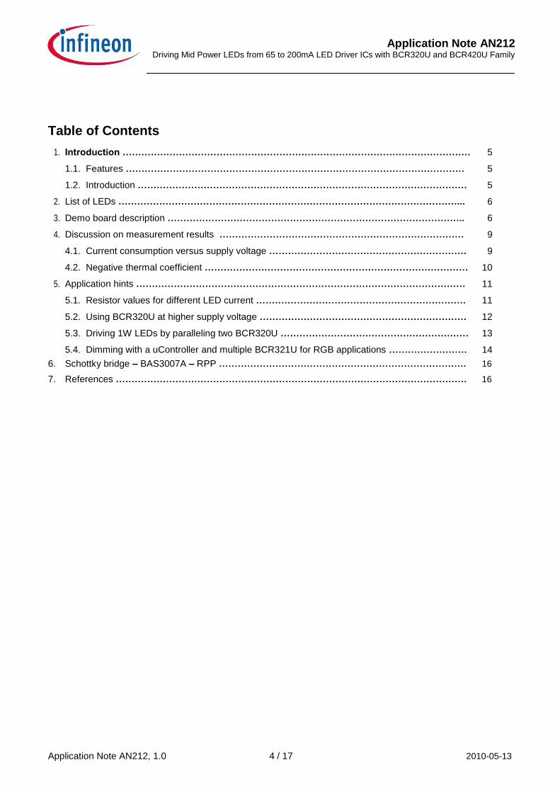
Table of Contents
1. Introduction ………………………………………………………………………………………………… 5
1.1. Features ……………………………………………………………………………………………… 5
1.2. Introduction …………………………………………………………………………………………… 5
2. List of LEDs ………………………………………………………………………………………………... 6
3. Demo board description ………………………………………………………………………………….. 6
4. Discussion on measurement results …………………………………………………………………… 9
4.1. Current consumption versus supply voltage ……………………………………………………… 9
4.2. Negative thermal coefficient ………………………………………………………………………… 10
5. Application hints …………………………………………………………………………………………… 11
5.1. Resistor values for different LED current …………………………………………………………. 11
5.2. Using BCR320U at higher supply voltage ………………………………………………………… 12
5.3. Driving 1W LEDs by paralleling two BCR320U …………………………………………………… 13
5.4. Dimming with a uController and multiple BCR321U for RGB applications ……………………. 14 6. Schottky bridge – BAS3007A – RPP ……………………………………………………………………. 16 7. References …………………………………………………………………………………………………. 16
Application Note AN212, 1.0 4 / 17 2010-05-13
Application Note AN212 Driving Mid Power LEDs from 65 to 200mA LED Driver ICs with BCR320U and BCR420U Family
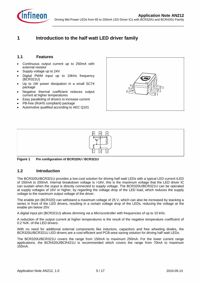
1 Introduction to the half watt LED driver family 1.1 Features Continuous output current up to 250mA with
external resistor
Supply voltage up to 24V Digital PWM input up to 10kHz frequency
(BCR321U) Up to 1W power dissipation in a small SC74
package Negative thermal coefficient reduces output
current at higher temperatures
Easy paralleling of drivers to increase current
PB-free (RoHS compliant) package
Automotive qualified according to AEC Q101 Figure 1 Pin configuration of BCR320U / BCR321U 1.2 Introduction The BCR320U/BCR321U provides a low-cost solution for driving half watt LEDs with a typical LED current ILED of 150mA to 200mA. Internal breakdown voltage is >16V, this is the maximum voltage that the LED driver IC can sustain when the ouput is directly connected to supply voltage. The BCR320U/BCR321U can be operated at supply voltages of 16V or higher, by regarding the voltage drop of the LED load, which reduces the supply voltage to the maximum output voltage of the driver. The enable pin (BCR320) can withstand a maximum voltage of 25 V, which can also be increased by stacking a series in front of the LED drivers, resulting in a certain voltage drop of the LEDs, reducing the voltage at the enable pin below 25V. A digital input pin (BCR321U) allows dimming via a Microcontroller with frequencies of up to 10 kHz. A reduction of the output current at higher temperatures is the result of the negative temperature coefficient of 0.2 %/K. of the LED drivers. With no need for additional external components like inductors, capacitors and free wheeling diodes, the BCR320U/BCR321U LED drivers are a cost-efficient and PCB-area saving solution for driving half watt LEDs. The BCR320U/BCR321U covers the range from 150mA to maximum 250mA. For the lower current range applications, the BCR420U/BCR421U is recommended which covers the range from 70mA to maximum 150mA. Application Note AN212, 1.0 5 / 17 2010-05-13
Application Note AN212 Driving Mid Power LEDs from 65 to 200mA LED Driver ICs with BCR320U and BCR420U Family
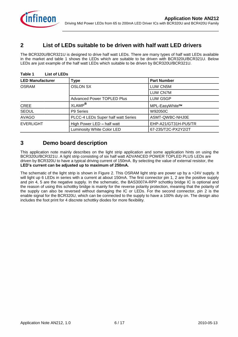
2 List of LEDs suitable to be driven with half watt LED drivers The BCR320U/BCR321U is designed to drive half watt LEDs. There are many types of half watt LEDs available in the market and table 1 shows the LEDs which are suitable to be driven with BCR320U/BCR321U. Below LEDs are just example of the half watt LEDs which suitable to be driven by BCR320U/BCR321U.
Table 1 List of LEDs
LED Manufacturer Type Part Number
OSRAM OSLON SX LUW CN5M
LUW CN7M
Advanced Power TOPLED Plus LUW G5GP
CREE XLAMP
MPL-EasyWhite
SEOUL P9 Series W92050C
AVAGO PLCC-4 LEDs Super half watt Series ASMT-QWBC-NHJ0E
EVERLIGHT High Power LED – half watt EHP-A21/GT31H-PU5/TR Luminosity White Color LED 67-235/T2C-PX2Y2/2T
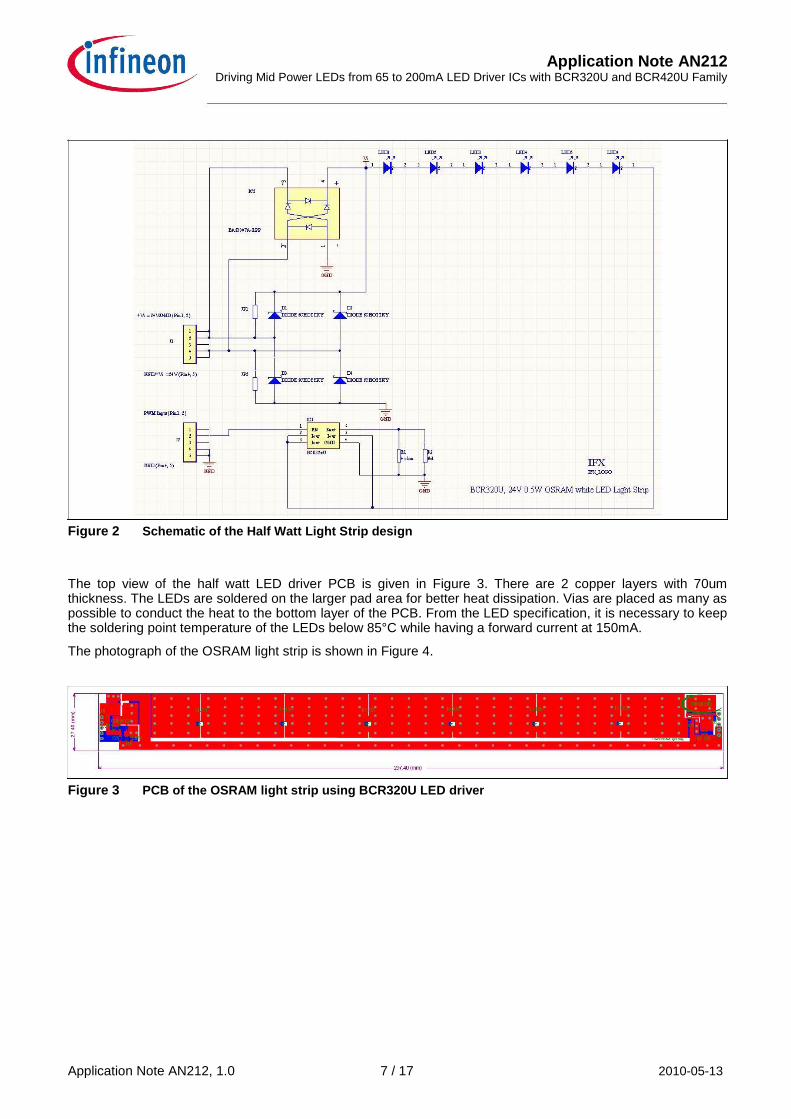
3 Demo board description This application note mainly describes on the light strip application and some application hints on using the BCR320U/BCR321U. A light strip consisting of six half watt ADVANCED POWER TOPLED PLUS LEDs are driven by BCR320U to have a typical driving current of 150mA. By selecting the value of external resistor, the LED’s current can be adjusted up to maximum of 250mA. The schematic of the light strip is shown in Figure 2. This OSRAM light strip are power up by a +24V supply. It will light up 6 LEDs in series with a current at about 150mA. The first connector pin 1, 2 are the positive supply and pin 4, 5 are the negative supply. In the schematic, the BAS3007A-RPP schottky bridge IC is optional and the reason of using this schottky bridge is mainly for the reverse polarity protection, meaning that the polarity of the supply can also be reversed without damaging the IC or LEDs. For the second connector, pin 2 is the enable signal for the BCR320U, which can be connected to the supply to have a 100% duty on. The design also includes the foot print for 4 discrete schottky diodes for more flexibility.
Application Note AN212, 1.0 6 / 17 2010-05-13
Application Note AN212 Driving Mid Power LEDs from 65 to 200mA LED Driver ICs with BCR320U and BCR420U Family
Figure 2 Schematic of the Half Watt Light Strip design
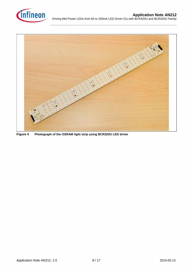
The top view of the half watt LED driver PCB is given in Figure 3. There are 2 copper layers with 70um thickness. The LEDs are soldered on the larger pad area for better heat dissipation. Vias are placed as many as possible to conduct the heat to the bottom layer of the PCB. From the LED specification, it is necessary to keep the soldering point temperature of the LEDs below 85°C while having a forward current at 150mA. The photograph of the OSRAM light strip is shown in Figure 4. Figure 3 PCB of the OSRAM light strip using BCR320U LED driver
Application Note AN212, 1.0 7 / 17 2010-05-13
Application Note AN212 Driving Mid Power LEDs from 65 to 200mA LED Driver ICs with BCR320U and BCR420U Family
Figure 4 Photograph of the OSRAM light strip using BCR320U LED driver
Application Note AN212, 1.0 8 / 17 2010-05-13
Application Note AN212 Driving Mid Power LEDs from 65 to 200mA LED Driver ICs with BCR320U and BCR420U Family
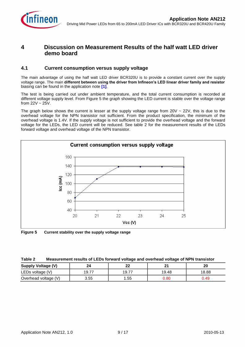
4 Discussion on Measurement Results of the half watt LED driver demo board
4.1 Current consumption versus supply voltage The main advantage of using the half watt LED driver BCR320U is to provide a constant current over the supply
voltage range. The main different between using the driver from Infineon’s LED linear driver family and resistor biasing can be found in the application note [1]. The test is being carried out under ambient temperature, and the total current consumption is recorded at different voltage supply level. From Figure 5 the graph showing the LED current is stable over the voltage range from 22V ~ 25V. The graph below shows the current is lesser at the supply voltage range from 20V ~ 22V, this is due to the overhead voltage for the NPN transistor not sufficient. From the product specification, the minimum of the overhead voltage is 1.4V. If the supply voltage is not sufficient to provide the overhead voltage and the forward voltage for the LEDs, the LED current will be reduced. See table 2 for the measurement results of the LEDs forward voltage and overhead voltage of the NPN transistor.
Figure 5 Current stability over the supply voltage range Table 2 Measurement results of LEDs forward voltage and overhead voltage of NPN transistor
Supply Voltage (V) 24 22 21 20
LEDs voltage (V) 19.77 19.77 19.48 18.88
Overhead voltage (V) 3.55 1.55 0.80 0.49
Application Note AN212, 1.0 9 / 17 2010-05-13
Application Note AN212 Driving Mid Power LEDs from 65 to 200mA LED Driver ICs with BCR320U and BCR420U Family
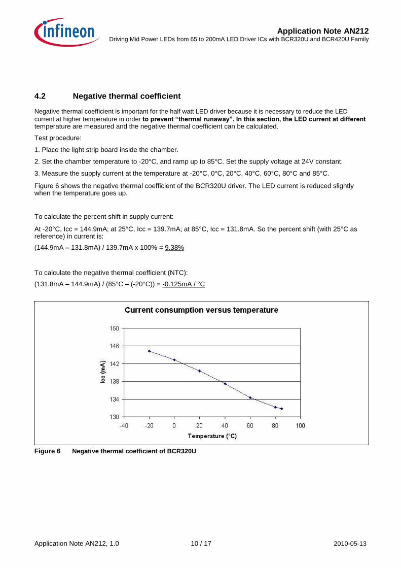
4.2 Negative thermal coefficient Negative thermal coefficient is important for the half watt LED driver because it is necessary to reduce the LED
current at higher temperature in order to prevent “thermal runaway”. In this section, the LED current at different temperature are measured and the negative thermal coefficient can be calculated. Test procedure: 1. Place the light strip board inside the chamber. 2. Set the chamber temperature to -20°C, and ramp up to 85°C. Set the supply voltage at 24V constant. 3. Measure the supply current at the temperature at -20°C, 0°C, 20°C, 40°C, 60°C, 80°C and 85°C. Figure 6 shows the negative thermal coefficient of the BCR320U driver. The LED current is reduced slightly when the temperature goes up. To calculate the percent shift in supply current: At -20°C, Icc = 144.9mA; at 25°C, Icc = 139.7mA; at 85°C, Icc = 131.8mA. So the percent shift (with 25°C as reference) in current is: (144.9mA – 131.8mA) / 139.7mA x 100% = 9.38%
To calculate the negative thermal coefficient (NTC):
(131.8mA – 144.9mA) / (85°C – (-20°C)) = -0.125mA / °C
Figure 6 Negative thermal coefficient of BCR320U
Application Note AN212, 1.0 10 / 17 2010-05-13
Application Note AN212 Driving Mid Power LEDs from 65 to 200mA LED Driver ICs with BCR320U and BCR420U Family
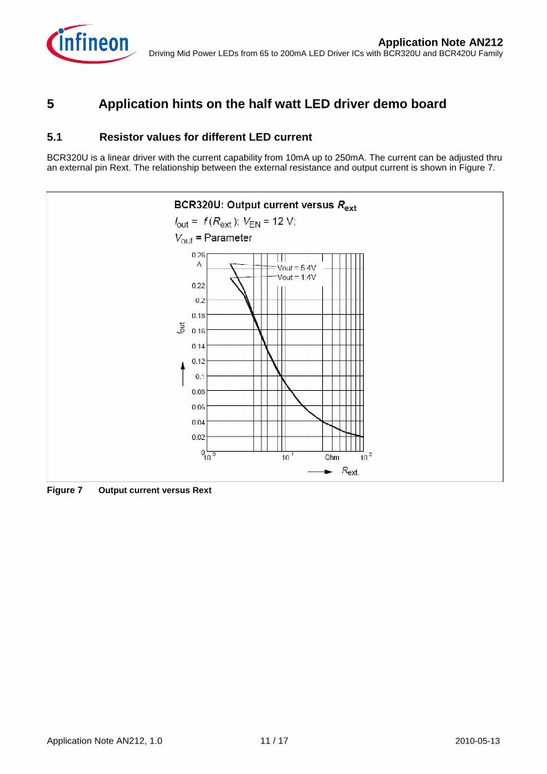
5 Application hints on the half watt LED driver demo board 5.1 Resistor values for different LED current BCR320U is a linear driver with the current capability from 10mA up to 250mA. The current can be adjusted thru an external pin Rext. The relationship between the external resistance and output current is shown in Figure 7.
Figure 7 Output current versus Rext Application Note AN212, 1.0 11 / 17 2010-05-13
Application Note AN212 Driving Mid Power LEDs from 65 to 200mA LED Driver ICs with BCR320U and BCR420U Family
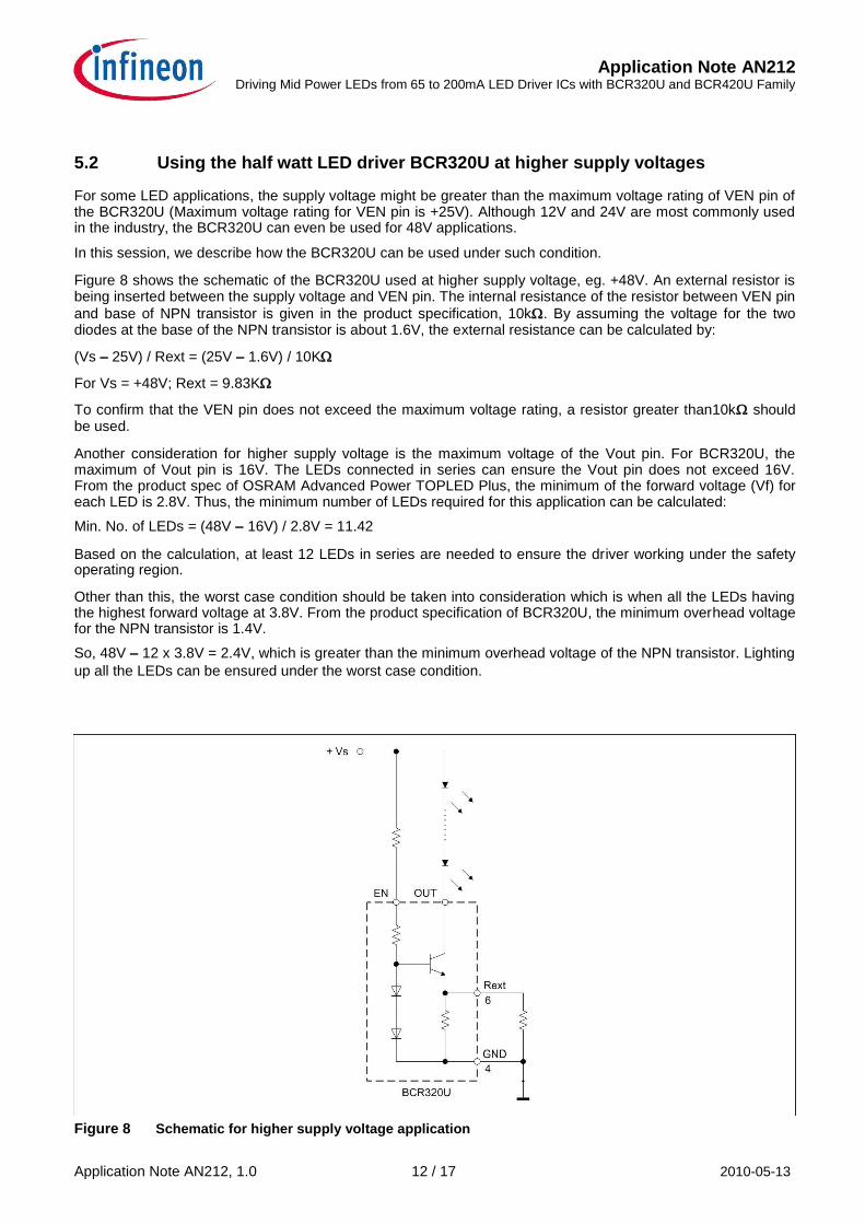
5.2 Using the half watt LED driver BCR320U at higher supply voltages For some LED applications, the supply voltage might be greater than the maximum voltage rating of VEN pin of the BCR320U (Maximum voltage rating for VEN pin is +25V). Although 12V and 24V are most commonly used in the industry, the BCR320U can even be used for 48V applications. In this session, we describe how the BCR320U can be used under such condition. Figure 8 shows the schematic of the BCR320U used at higher supply voltage, eg. +48V. An external resistor is being inserted between the supply voltage and VEN pin. The internal resistance of the resistor between VEN pin
and base of NPN transistor is given in the product specification, 10k. By assuming the voltage for the two diodes at the base of the NPN transistor is about 1.6V, the external resistance can be calculated by: (Vs – 25V) / Rext = (25V – 1.6V) / 10K For Vs = +48V; Rext = 9.83K To confirm that the VEN pin does not exceed the maximum voltage rating, a resistor greater than10k should be used. Another consideration for higher supply voltage is the maximum voltage of the Vout pin. For BCR320U, the maximum of Vout pin is 16V. The LEDs connected in series can ensure the Vout pin does not exceed 16V. From the product spec of OSRAM Advanced Power TOPLED Plus, the minimum of the forward voltage (Vf) for each LED is 2.8V. Thus, the minimum number of LEDs required for this application can be calculated: Min. No. of LEDs = (48V – 16V) / 2.8V = 11.42 Based on the calculation, at least 12 LEDs in series are needed to ensure the driver working under the safety operating region. Other than this, the worst case condition should be taken into consideration which is when all the LEDs having the highest forward voltage at 3.8V. From the product specification of BCR320U, the minimum overhead voltage for the NPN transistor is 1.4V. So, 48V – 12 x 3.8V = 2.4V, which is greater than the minimum overhead voltage of the NPN transistor. Lighting
up all the LEDs can be ensured under the worst case condition. Figure 8 Schematic for higher supply voltage application
Application Note AN212, 1.0 12 / 17 2010-05-13
Application Note AN212 Driving Mid Power LEDs from 65 to 200mA LED Driver ICs with BCR320U and BCR420U Family
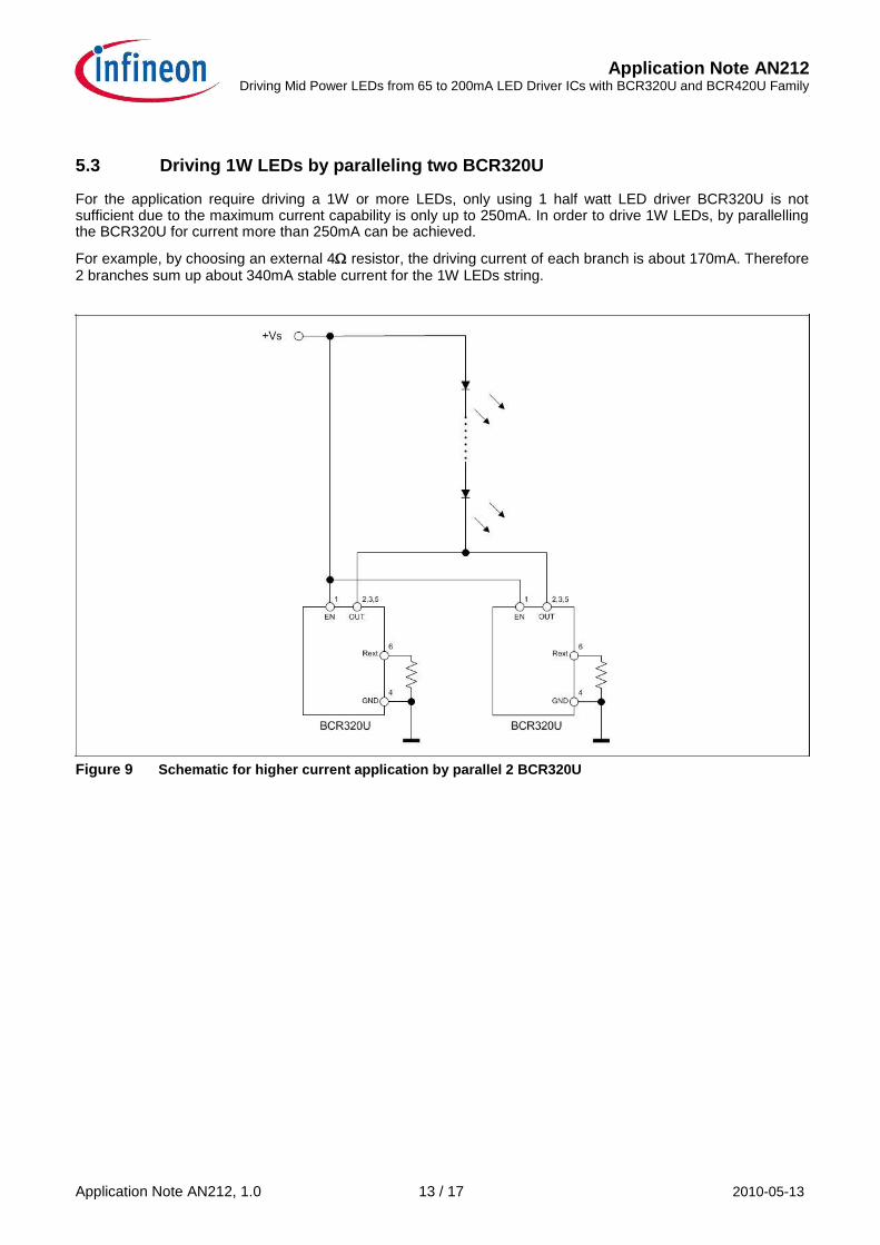
5.3 Driving 1W LEDs by paralleling two BCR320U For the application require driving a 1W or more LEDs, only using 1 half watt LED driver BCR320U is not sufficient due to the maximum current capability is only up to 250mA. In order to drive 1W LEDs, by parallelling the BCR320U for current more than 250mA can be achieved. For example, by choosing an external 4 resistor, the driving current of each branch is about 170mA. Therefore 2 branches sum up about 340mA stable current for the 1W LEDs string. Figure 9 Schematic for higher current application by parallel 2 BCR320U Application Note AN212, 1.0 13 / 17 2010-05-13
Application Note AN212 Driving Mid Power LEDs from 65 to 200mA LED Driver ICs with BCR320U and BCR420U Family
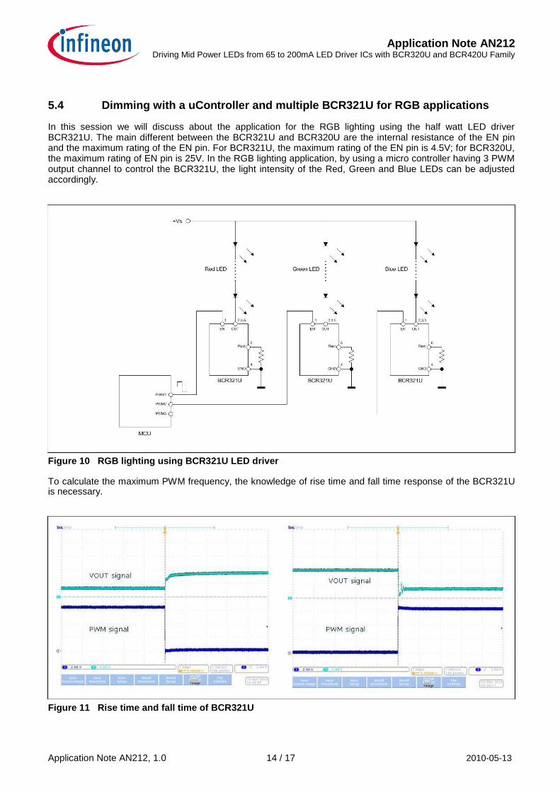
5.4 Dimming with a uController and multiple BCR321U for RGB applications In this session we will discuss about the application for the RGB lighting using the half watt LED driver BCR321U. The main different between the BCR321U and BCR320U are the internal resistance of the EN pin and the maximum rating of the EN pin. For BCR321U, the maximum rating of the EN pin is 4.5V; for BCR320U, the maximum rating of EN pin is 25V. In the RGB lighting application, by using a micro controller having 3 PWM output channel to control the BCR321U, the light intensity of the Red, Green and Blue LEDs can be adjusted accordingly.
Figure 10 RGB lighting using BCR321U LED driver To calculate the maximum PWM frequency, the knowledge of rise time and fall time response of the BCR321U is necessary.
Figure 11 Rise time and fall time of BCR321U Application Note AN212, 1.0 14 / 17 2010-05-13
Application Note AN212 Driving Mid Power LEDs from 65 to 200mA LED Driver ICs with BCR320U and BCR420U Family
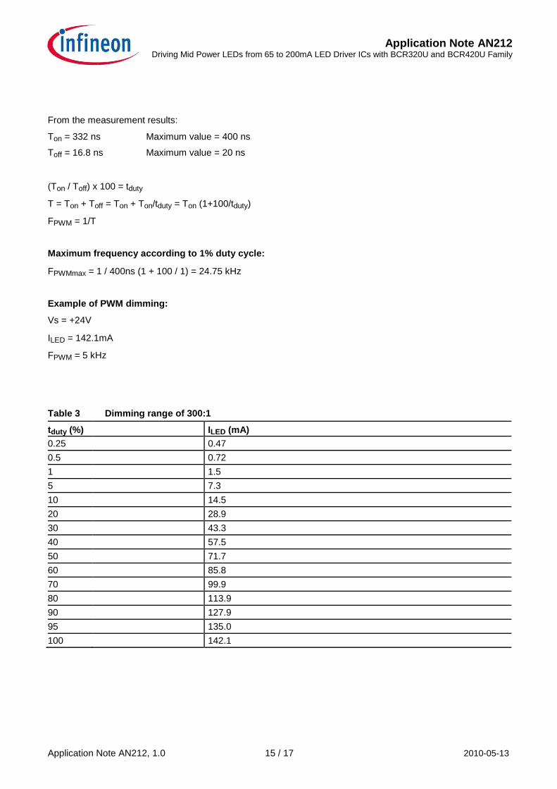
From the measurement results: Ton = 332 ns Maximum value = 400 ns Toff = 16.8 ns Maximum value = 20 ns
(Ton / Toff) x 100 = tduty T = Ton + Toff = Ton + Ton/tduty = Ton (1+100/tduty) FPWM = 1/T Maximum frequency according to 1% duty cycle: FPWMmax = 1 / 400ns (1 + 100 / 1) = 24.75 kHz Example of PWM dimming: Vs = +24V ILED = 142.1mA FPWM = 5 kHz
Table 3 Dimming range of 300:1
tduty (%) ILED (mA)
0.25 0.47
0.5 0.72
1 1.5
5 7.3
10 14.5
20 28.9
30 43.3
40 57.5
50 71.7
60 85.8
70 99.9
80 113.9
90 127.9
95 135.0
100 142.1
Application Note AN212, 1.0 15 / 17 2010-05-13
Application Note AN212 Driving Mid Power LEDs from 65 to 200mA LED Driver ICs with BCR320U and BCR420U Family
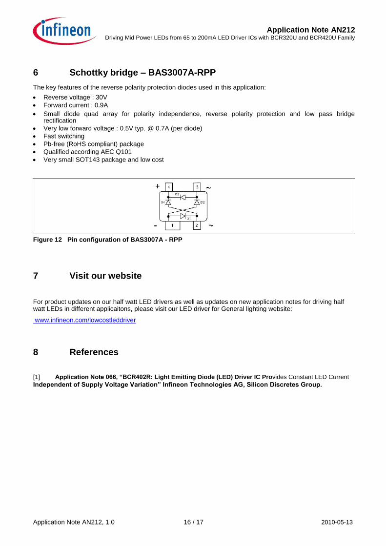
6 Schottky bridge – BAS3007A-RPP The key features of the reverse polarity protection diodes used in this application: Reverse voltage : 30V
Forward current : 0.9A Small diode quad array for polarity independence, reverse polarity protection and low pass bridge
rectification
Very low forward voltage : 0.5V typ. @ 0.7A (per diode)
Fast switching
Pb-free (RoHS compliant) package
Qualified according AEC Q101
Very small SOT143 package and low cost Figure 12 Pin configuration of BAS3007A - RPP
7 Visit our website
For product updates on our half watt LED drivers as well as updates on new application notes for driving half watt LEDs in different applicaitons, please visit our LED driver for General lighting website: www.infineon.com/lowcostleddriver
8 References
[1] Application Note 066, “BCR402R: Light Emitting Diode (LED) Driver IC Provides Constant LED Current Independent of Supply Voltage Variation” Infineon Technologies AG, Silicon Discretes Group. Application Note AN212, 1.0 16 / 17 2010-05-13

w w w . i n f i n e o n . c o m
Published by Infineon Technologies AG AN212