driving multiple leds - noisemantra.com
TRANSCRIPT
Temple UniversitySchool of Communications and Theater
Physical Computing Spring 2010
Chris Vecchio
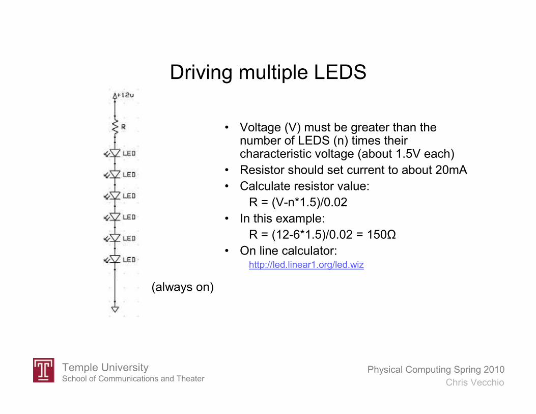
Driving multiple LEDS
• Voltage (V) must be greater than the number of LEDS (n) times their characteristic voltage (about 1.5V each)
• Resistor should set current to about 20mA
• Calculate resistor value:
R = (V-n*1.5)/0.02
• In this example:
R = (12-6*1.5)/0.02 = 150Ω
• On line calculator:http://led.linear1.org/led.wiz
(always on)

Temple UniversitySchool of Communications and Theater
Physical Computing Spring 2010
Chris Vecchio
Controlling multiple LEDS
• Voltage (V) must be greater than the number of LEDS (n) times their characteristic voltage (about 1.5V each)
• Resistor should set current to about 20mA
• Calculate resistor value:
R = (V-n*1.5)/0.02
• In this example:
R = (12-5*1.5)/0.02 = 225Ω
• On line calculator:http://led.linear1.org/led.wiz

Temple UniversitySchool of Communications and Theater
Physical Computing Spring 2010
Chris Vecchio
Serial Communications
• Practical way to connect to peripheral devices
– Gather sensor data
– Control transducers or output devices
• Information is sent over one wire
– Simplifies interconnections
– Total wires to device < 4 (power, GND, data in, data out)
• Can be synchronous or asynchronous
• Common protocols:
– RS232 (asynchronous, 1 transmitter – 1 receiver)
– I2C (synchronous, 1 transmitter – multiple receivers)
– SPI (synchronous, 1 transmitter – 1 receiver)

Temple UniversitySchool of Communications and Theater
Physical Computing Spring 2010
Chris Vecchio
RS232 The common PC “serial port”
Important parameters:
• Levels (15V or TTL)?
• Inverted?
• Baud?
• Total bits, stop bits, parity?
• Connectors 25 or 9 pin?

Temple UniversitySchool of Communications and Theater
Physical Computing Spring 2010
Chris Vecchio
RS232 Voltage Levels
• +/-15V or TTL (5V)
• The standard serial port uses +/-15V
• Do not connect a standard port directly to a microcontroller!
• Arduino pins 0 (receive) and 1 (transmit) are used for serial
communications
• Information can be sent to or received from PC
• Information can be sent to peripheral devices:
- LCD displays
- Voice synthesizers
- Video text overlay

Temple UniversitySchool of Communications and Theater
Physical Computing Spring 2010
Chris Vecchio
RS232 Example Serial Modules
• Speech
• Text (LCD display)
• Video overlay
• Multiple servo motor control
http://www.seetron.com/ilm216_1.htm
http://www.decadenet.com/bob4/bob4.html
http://www.sparkfun.com/commerce/product_info.php?products_id=8897
http://www.seetron.com/ssc.htm
http://www.rcsys.com/modules.htm

Temple UniversitySchool of Communications and Theater
Physical Computing Spring 2010
Chris Vecchio
RS232 Important Parameters
These parameters will be specified for any RS232 module:
• Baud (connection speed)
• Inverted signal (yes for TTL, no for standard RS232)
• Total bits per symbol (usually 8)
• Number of stop bits (usually 1)
• Parity (error checking, usually not used)
• Most common: “9600 baud 8N1”

Temple UniversitySchool of Communications and Theater
Physical Computing Spring 2010
Chris Vecchio
Bidirectional Serial Example/* continuously streams sensor data to PC */
/* monitors serial port for 'a' or 'b' bytes to control LED */
void setup()
Serial.begin(9600);
pinMode(13,OUTPUT);
void loop()
// read the analog input into a variable:
int analogValue = analogRead(0);
// Send the result to the PC:
Serial.println(analogValue);
// Read a character from the PC
byte inByte = Serial.read();
if (inByte == 'a') digitalWrite(13,HIGH); // if the letter “a” is sent turn
on the LED
if (inByte == 'b') digitalWrite(13,LOW); // if the letter “b” is sent turn
off the LED
// note the use of the single quote ‘ above
delay(100);
Temple UniversitySchool of Communications and Theater
Physical Computing Spring 2010
Chris Vecchio
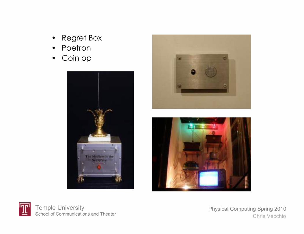
• Regret Box
• Poetron
• Coin op

Temple UniversitySchool of Communications and Theater
Physical Computing Spring 2010
Chris Vecchio
RS232 Important Parameters
These parameters will be specified for any RS232 module:
• AnalogInSerial
• Connect speaking board
• Inverted signal (yes for TTL, no for standard RS232)
• Total bits per symbol (usually 8)
• Number of stop bits (usually 1)
• Parity (error checking, usually not used)
• Most common: “9600 baud 8N1”

Temple UniversitySchool of Communications and Theater
Physical Computing Spring 2010
Chris Vecchio
Ping Distance Sensor
• 5V DC power (Vdd) goes to “5V”
• GND (Vss) connects to “GND”
• Signal pin connects to microcontroller I/O pin
Temple UniversitySchool of Communications and Theater
Physical Computing Spring 2010
Chris Vecchio
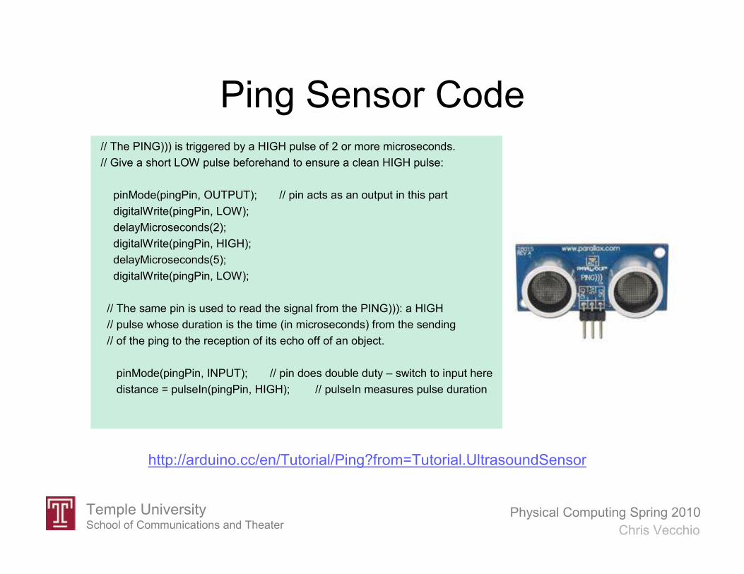
Ping Sensor Code// The PING))) is triggered by a HIGH pulse of 2 or more microseconds.
// Give a short LOW pulse beforehand to ensure a clean HIGH pulse:
pinMode(pingPin, OUTPUT); // pin acts as an output in this part
digitalWrite(pingPin, LOW);
delayMicroseconds(2);
digitalWrite(pingPin, HIGH);
delayMicroseconds(5);
digitalWrite(pingPin, LOW);
// The same pin is used to read the signal from the PING))): a HIGH
// pulse whose duration is the time (in microseconds) from the sending
// of the ping to the reception of its echo off of an object.
pinMode(pingPin, INPUT); // pin does double duty – switch to input here
distance = pulseIn(pingPin, HIGH); // pulseIn measures pulse duration
http://arduino.cc/en/Tutorial/Ping?from=Tutorial.UltrasoundSensor
Temple UniversitySchool of Communications and Theater
Physical Computing Spring 2010
Chris Vecchio
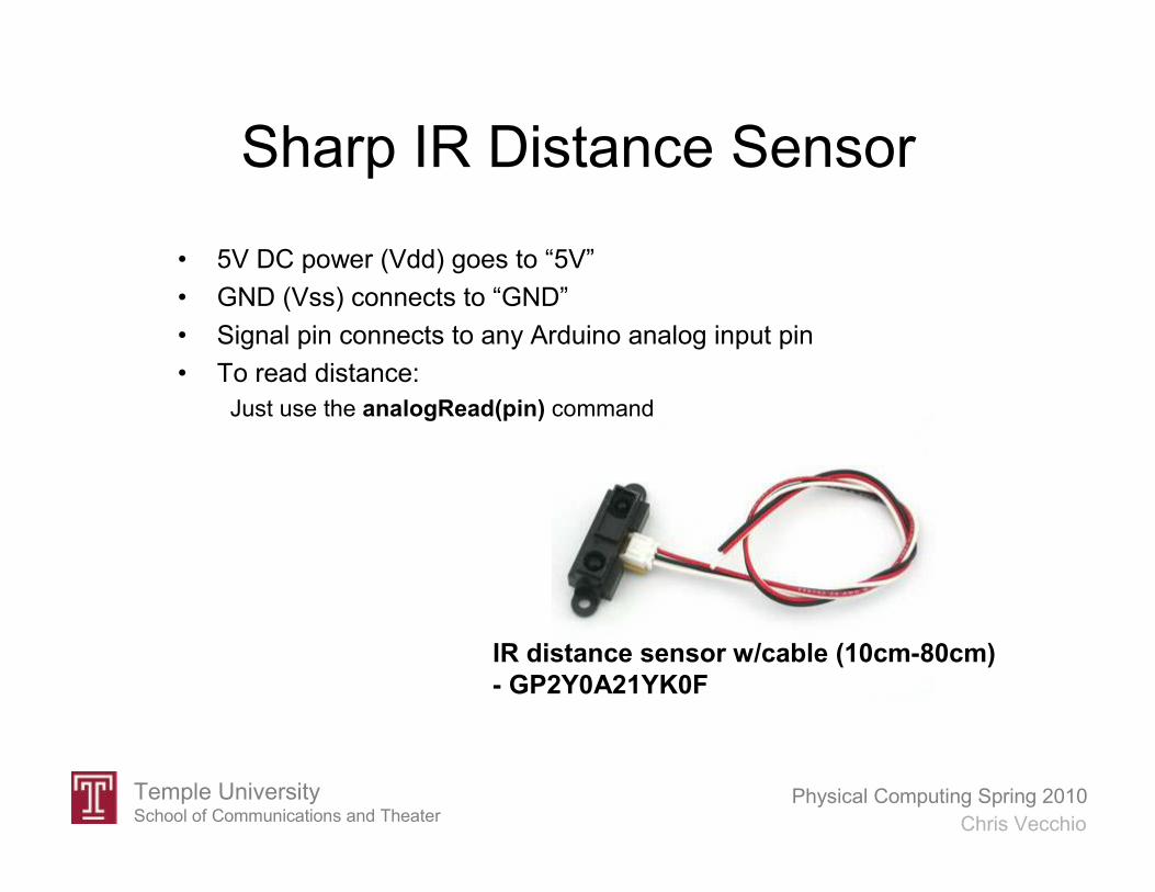
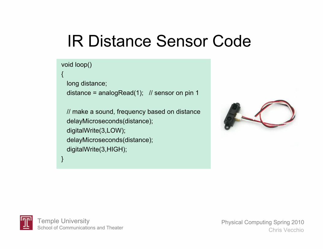
Sharp IR Distance Sensor
• 5V DC power (Vdd) goes to “5V”
• GND (Vss) connects to “GND”
• Signal pin connects to any Arduino analog input pin
• To read distance:
Just use the analogRead(pin) command
IR distance sensor w/cable (10cm-80cm)
- GP2Y0A21YK0F
Temple UniversitySchool of Communications and Theater
Physical Computing Spring 2010
Chris Vecchio
IR Distance Sensor Code
void loop()
long distance;
distance = analogRead(1); // sensor on pin 1
// make a sound, frequency based on distance
delayMicroseconds(distance);
digitalWrite(3,LOW);
delayMicroseconds(distance);
digitalWrite(3,HIGH);

Interfaceable Sound Modules
• Wave Shield
• Cheaper solutions:
Sound toys
Sound greeting cards
Talking picture frames
Digital voice recorders
MP3 players
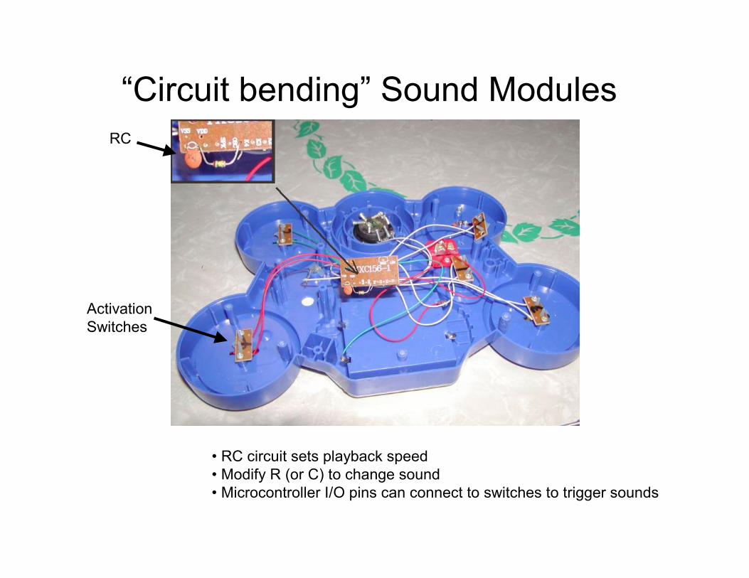
“Circuit bending” Sound Modules
• RC circuit sets playback speed
• Modify R (or C) to change sound
• Microcontroller I/O pins can connect to switches to trigger sounds
RC
Activation
Switches
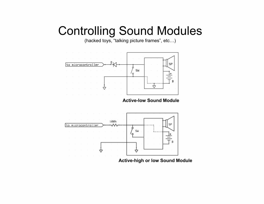
Controlling Sound Modules (hacked toys, “talking picture frames”, etc…)
Active-low Sound Module
Active-high or low Sound Module

Temple UniversitySchool of Communications and Theater
Physical Computing Spring 2010
Chris Vecchio
Distance Sensing
Drum Machine Code
/* PingDrummer */
const int pingPin = 7; //ping sensor
void setup()
Serial.begin(9600);
// hacked toy drum machine connections
pinMode(13,OUTPUT); //drum sound #1
pinMode(12,OUTPUT); //drum sound #2
pinMode(11,OUTPUT); //drum sound #3
void loop()
long duration;
// The PING))) is triggered by a HIGH pulse of 2 or more microseconds.
// Give a short LOW pulse beforehand to ensure a clean HIGH pulse:
pinMode(pingPin, OUTPUT);
digitalWrite(pingPin, LOW);
delay(2);
digitalWrite(pingPin, HIGH);
delayMicroseconds(5);
digitalWrite(pingPin, LOW);
// The same pin is used to read the signal from the PING))): a HIGH
// pulse whose duration is the time (in microseconds) from the sending
// of the ping to the reception of its echo off of an object.
pinMode(pingPin, INPUT);
duration = pulseIn(pingPin, HIGH);
if (duration<1500) Serial.println(duration);
if (duration<1500) drum1(); // close object detected
if (duration>1500 and duration<3000) drum2(); // intermediate range object detected
if (duration>3000 and duration<4500) drum3(); // farther object detected
void drum1(void)
digitalWrite(13, HIGH);
delay(40); // 40ms high pulse triggers drum
digitalWrite(13, LOW);
delay(200); // wait for sound to finish
void drum2(void)
digitalWrite(12, HIGH);
delay(40);
digitalWrite(12, LOW);
delay(200);
void drum3(void)
digitalWrite(11, HIGH);
delay(40);
digitalWrite(11, LOW);
delay(200);

Temple UniversitySchool of Communications and Theater
Physical Computing Spring 2010
Chris Vecchio
Window to the Past
The device is based on two
off-the-shelf digital audio
recorders controlled by a
BasicStamp.
A 3 minute audio delay line situated in a
public restroom. At any given time the
viewer is hearing whatever happened in
the room 3 minutes prior. By its nature,
the portal can also be used to “leave a
message for the next person in (the
bathroom) line”. Window to the Past
addresses issues of privacy, surveillance,
and the supposed neutrality of
technological devices.
Temple UniversitySchool of Communications and Theater
Physical Computing Spring 2010
Chris Vecchio
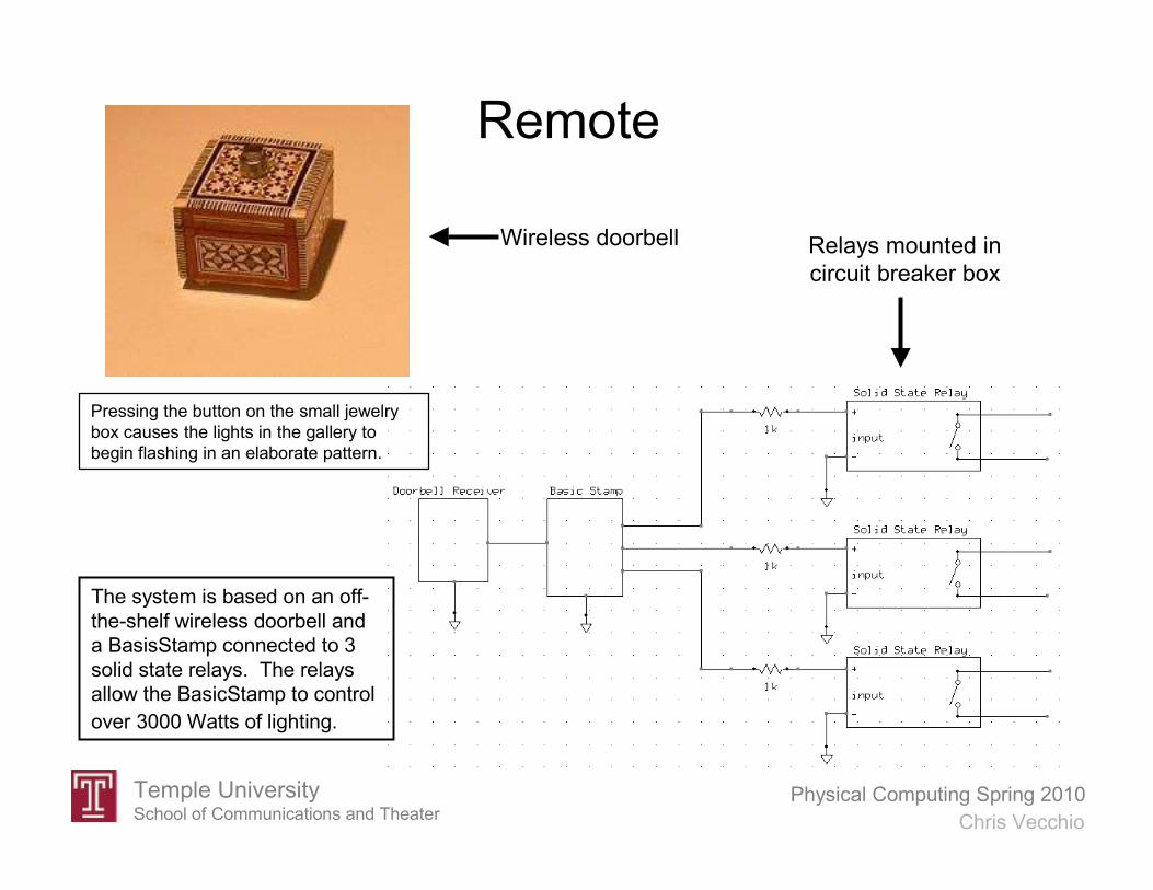
Remote
Relays mounted in
circuit breaker box
Wireless doorbell
Pressing the button on the small jewelry
box causes the lights in the gallery to
begin flashing in an elaborate pattern.
The system is based on an off-
the-shelf wireless doorbell and
a BasisStamp connected to 3
solid state relays. The relays
allow the BasicStamp to control
over 3000 Watts of lighting.

General Interface Techniques
Buttons on device can be
controlled from microcontroller
Buttons on remote can be controlled
from microcontroller
(Hint: buy a universal remote to hack)
Almost any consumer electronic device
can be controlled this way:
• DVD players
• MP3 players
• Receivers
• Ceiling fans, fireplaces!
• etc…
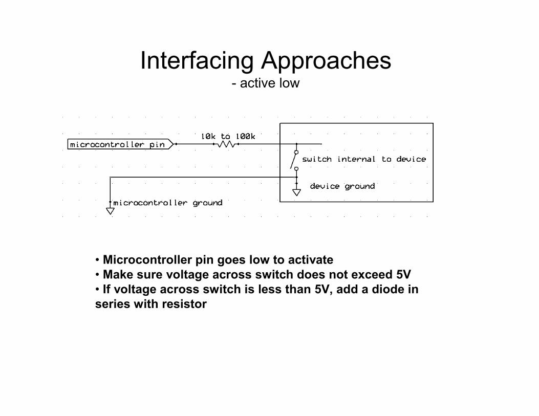
Interfacing Approaches- active low
• Microcontroller pin goes low to activate
• Make sure voltage across switch does not exceed 5V
• If voltage across switch is less than 5V, add a diode in
series with resistor

Interfacing Approaches- active high
• Microcontroller pin goes high to activate
• Make sure voltage across switch does not exceed 5V

A Universal Interfacing Approach
Multiple instances of this circuit can
be used to control multiple functions:
• Play
• Stop
• Next track
• Etc…Small 5V, 20mA reed relays can be
driven directly by an Arduino output

Interleaving Operations
/* Flash LED and make sound */
void setup()
pinMode(2, OUTPUT); // connect speaker to pin 2
pinMode(13, OUTPUT); // LED
void loop()
// make sound by sending pin 2 high and low every 1000 microseconds
digitalWrite(2, HIGH);
delayMicroseconds(500);
digitalWrite(2, LOW);
delayMicroseconds(500);
// flash LED on pin 13 every second
digitalWrite(13, HIGH);
delay(1000);
digitalWrite(13, LOW);
delay(1000);
Why won’t this program work?

Temple UniversitySchool of Communications and Theater
Physical Computing Spring 2010
Chris Vecchio
Technical Assignment For Thursday March 4th
• Create a program that makes a continuous 1000Hz tone and simultaneously
flashes an LED – on for 1 second, off for 1 second. Hint: modify the
BlinkWithoutDelay example.
• Then modify the program so that the LED can be turned on or off using 'a' or 'b'
characters sent from the serial terminal. Please email your two versions of this
program to me or bring a hardcopy with you to class. You can test your code
using a small speaker or one of the piezo speakers we have used in class. If you
can’t get access to these or are having trouble with the assignment please
contact me.
Remember, many code examples are also available here:
http://arduino.cc/en/Tutorial/HomePage
And some more serial communications information can be found here:
http://www.ladyada.net/learn/arduino/lesson4.html