drn@ - universiti sains malaysiacivil.eng.usm.my/drn/newsletter/vol1no2.pdftwo of the most...
TRANSCRIPT

DRN@
Assoc. Prof Dr Rozi Abdullah Dr Fadzli Mohamed N azri
Microtremor Measurement in Penang Island-A Collaborative Research Project between USM & TokyoTech .................................. 1
Using Discrete Wavelet Transforms (DWT) In Time-History Analysis of Double Layer Cylindrical Space Truss Roofs ................................ .4
2-Day Workshop on Blast Effects on Building & Offshore Structures .................. 7
I-Day Seminar on Geohazard ..................... 8
Microtremor Measurement in Penang Island - A Collaborative Research Project between Universiti Sains Malaysia and Tokyo Institute of Technology
Lau Tze Liang DRN, School of Civil Engineering, Universiti Sains Malaysia [email protected]
Malaysia is located in seismically stable Sunda plate and had not experienced any disasterous earthquake occurrences. However, due to the location close to two of the most seismically active plate boundaries, i.e. Indo-Australian and Eurasion plates, Malaysia has experienced numerous strong tremors caused by earthquakes in those two seismically active zones recently. The felt tremor becomes more frequent in the last decade due to the increment of the seismic activity since the major earthquake in Banda Aceh and the unprecedented Indian Ocean Tsunami in 2004. Even though Malaysia is located far from seismic sources, it has a substantial seismic risk from distant earthquakes due to the local geology such as the underlying soft soil tends to amplify ground motions. Therefore, it is imperative to conduct a detailed site-specific seIsmIC hazard assessment and produce seIsmIC micro zonation map for specific sites.
In order to achieve this objective, mircrotremor survey has been conducted through a collaborative research project between Disaster Research Nexus, Universiti Sains Malaysia (USM) and Tokyo Institute of Technology (TokyoTech), Japan. The project is funded by JICA AUN/SEED-Net. This collaborative project is headed by Dr. Lau Tze Liang and the co-researchers are Assoc. Prof. Dr. Taksiah A. Majid (USM) and Professor Dr. Hitoshi Morikawa (TokyoTech). The team members involved in this project consist of undergraduate and postgraduate students from both universities as follows:
USM : Chow Tze Liang; Leow Chee Sin; Lim Tse Yang; Moon Wei Chek; Tan Kang Chin; Tan Kwang Yew; Tan Teik Ning.
TokyoTech Shohei Hamasaki; Shohei Nakamura; Yumiko Ogura

The project focuses on the eastern part ofPenang Island where the capital of the state ofPenang is located. It is a highly urbanized with high-rise buildings and important structures and is an economically important area in Malaysia. The microtremor observation is carried out to measure the low amplitude of ambient vibration caused by either human-made or atmospheric disturbance. This research has introduced and promoted the application of new seismic survey technique for the estimation of dynamic characteristics of ground motion in Malaysia. Two types of microtremor measurements namely single point observation and array observation are conducted.
1. Single Point Observation
Single point observation using microtremor instrument was carried out from March to August 2012. A total of 322 points were measured in the eastern part of Penang Island. The observation points are located within 500 m to 1000 m apart. Figure 1 shows the microtremor observation at various locations in Penang Island. The sensor is placed on the ground to measure the ground motion in three directions at the same time. Microtremor measurement is recorded for three to five minutes by data logger. After the measurement, Fourier spectrum for each component is calculated using MATLAB program. From the spectra ratio of horizontal to vertical component, the predominant period and the amplification factor of the ground at that particular site are obtained and mapped.
Figure 1 Single point microtremor observation
2. Array Observation
Microtremor array observation is conducted together with the team from TokyoTech from 1 to 11 August 2012. The purpose of this survey is to estimate the substructure of the ground. The array observation is carried out at 15 sites in the eastern part of Penang Island. Two or three types of triangular array networks with the radii varies from 3 m to 70 m are formed based on the condition of the site. Figure 2 shows the observation activities during the field work. Four velocity sensors are used in each array observation. The recorded data will then be analyzed in TokyoTech using the program developed in Morikawa Laboratory .
g -----------------DRN Vol 1 (2), June 2012

Figure 2 Microtremor array observation
Conclusion
The outcome of the microtremor survey done in the eastern part of Penang Island has provided a useful information that is essential for seismic design. From this research project, USM team has acquired the relatively new technique seismic survey through technology transfer and guidance given by Tokyo Institute of Technology. This is in line with the transformation of the higher education through human capital development in USM. This research project also provides a better platform for researchers and students from both institutions to interact and discuss important issues related to earthquake engineering. From this collaborative research project between USM and Tokyo Institute of Technology, the successful network has been built and strengthened. This will definitely foster more research collaboration in near future.
As the celebration of the success of the field work and appreciation to the TokyoTech and USM teams, a farewell party is conducted in a typical Japanese way on 12 August 2012. Figure shows the Presentation of token of appreciation to Prof. Morikawa, Mr Hamasaki, Ms. Ogura and Mr. Nakamura for their selfless commitment to this project. Not to forget is the invaluable contribution from USM team who had worked hard to pursue new knowledge and skills that had not been learned in the classroom. These have led to the success of this joint research project.
-------------------------. DRN Vol 1 (2), June 2012
Using Discrete Wavelet Transforms (DWT) In Time History Analysis of Double Layer Cylindrical
Space Truss Roofs
Morteza Jamshidi!; Taksiah A. Majid2; Amin Esamaeil Ramaji3;
\,3Ph.D Candidate, School of Civil Engineering, Universiti Sains Malaysia
2DRN, School of Civil Engineering, Universiti Sains Malaysia
1 Jamshidi. [email protected]
Space trusses are one of the lightest steel structures with three-dimensional and complex structural behaviors made of thousands of steel tubular bars connected together by nodes. The very high degree of indeterminacy, their multiple redundancies and their appropriate three-dimensional geometrical form provide additional margins of safety to prevent them from sudden collapse in the case of accidental local failure of one or more elements, when the overall loading is below the service load.
Despite the earlier assumptions, recent studies show that where strong earthquakes are probable, these structures are vulnerable to seismic failures, especially when roofs are covered with snow (Sadeghi and Amani, 2012). But it must regarded that dynamic analysis of a space truss is, in some manner, a cumbersome procedure due to extreme complexity of structural configuration and numerous degree of freedoms, as well as a node to node distribution of mass which would consequently results in a complicated dynamic response. So some engineers refuse to perform the dynamic analysis of space truss in their designs. Therefore, it is preferred to decompose the earthquake acceleration into a small points signal by using mathematical method. Wavelet transforms (WT) is one of the famous method which may be used in the signal processing. Some advantages of using WT in the earthquake, wind and ocean is shown by researchers (Salajegheh et al., 2005).
1. Wavelet Transforms
Continues wavelet transforms (CWT) and discrete wavelet transforms are two kind of wavelet transform:
1. 1. Continues wavelet transform (CWT)
The continuous wavelet transform (CWT) is defined as the sum over all time of the signal multiplied by scaled, shifted versions of the wavelet function !jf:
00
C(scale,position) = f f(t) If/ (scale,position,t)dt (1)
The results of the CWT are many wavelet coefficients C, which are a function of scale and position. Multiplying each coefficient by the appropriately scaled and shifted wavelet yields the constituent wavelets of the original signal. Scaling a wavelet simply means stretching (or compressing) it. The scale is related to the frequency of the signal. Unlike the discrete wavelet transform, the CWT can operate at every scale, from that of the original signal up to some maximum scale that you determine by trading off your need for detailed analysis with available computational horsepower.
1. 2. Discrete wavelet transforms
Calculating wavelet coefficients at every possible scale is a fair amount of work, and it generates an awful lot of data. It seems that if the scales and positions are chosen based on powers of two so-called dyadic scales and positions then the analysis will be much more efficient and just as accurate .
• ~---------------DRN Vol 1 (2), June 2012
This analysis is obtained from the discrete wavelet transform (DWT). An efficient way to implement this scheme using filters was developed in 1988 by Mallat (Mallat, 1989). For many signals, the low-frequency content is the most important part. It is what gives the signal its identity. The high-frequency content, on the other hand, imparts flavor or nuance.
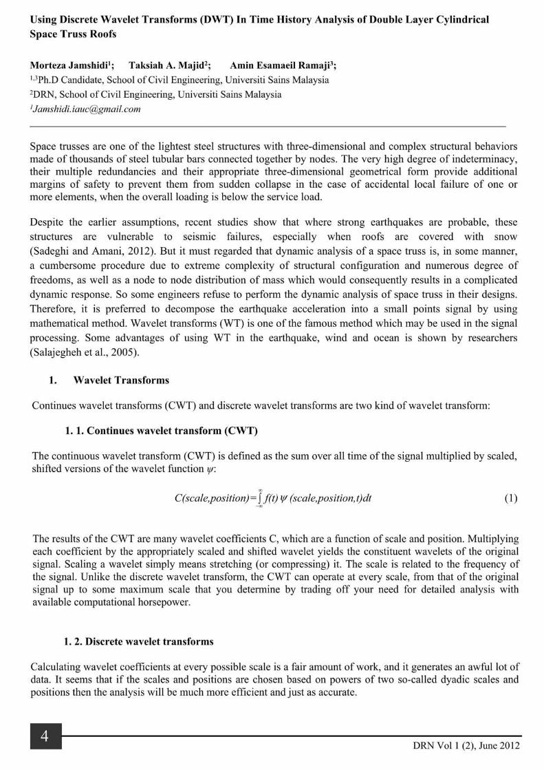
Consider the human voice, if you remove the high-frequency components, the voice sounds different, but you can still tell what's being said. However, if you remove enough of the low-frequency components, you hear gibberish. Approximations and details are two main concepts in wavelet analysis. The approximations are the high-scale, low-frequency components of the signal. The details are the low-scale, high-frequency components. The filtering process, at its most basic level, looks like as shown in Figure la.
cD High Frequency
I~CD-~ S I .... 5QO o W[ coeffjcients
!VV\ 1000 data points cA Low Frequency
L§-CD-MJ\ -500 D WI coefficients
(a) (b) Figure 1 a) High and low frequency filtering; b) the wavelet decomposition tree
The original signal, S, passes through two complementary filters and emerges as two signals. The decomposition process can be iterated, with successive approximations being decomposed in tum, so that one signal is broken down into many lower resolution components. This is called the wavelet decomposition tree (Figure 1 b).
1.2.1. Number of Levels and Wavelet Families
Since the analysis process is iterative, in theory it can be continued indefinitely. In reality, the decomposition can proceed only until the individual details consist of a single sample or pixel. In practice, you'll select a suitable number of levels based on the nature of the signal, or on a suitable criterion. There are different types of wavelet families such as Haar wavelet, Daubechies wavelets, Symlets, Meyer wavelet and so on. The qualities these families vary according to several criteria.
1.2.2. Time history analysis
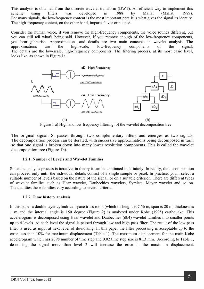
In this paper a double layer cylindrical space truss roofs (which its height is 7.56 m, span is 20 m, thickness is 1 m and the internal angle is 150 degree (Figure 2) is analyzed under Kobe (1995) earthquake. This accelerogram is decomposed using Haar wavelet and Daubechies (db4) wavelet families into smaller points up to 4 levels. At each level the signal is passed through low and high pass filter. The result of the low pass filter is used as input at next level of de-noising. In this paper the filter processing is acceptable up to the error less than 10% for maximum displacement (Table 1). The maximum displacement for the main Kobe accelerogram which has 2398 number of time step and 0.02 time step size is 81.3 mm. According to Table 1, de-noising the signal more than level 2 will increase the error in the maximum displacement.
----------------~. DRN Vol 1 (2), June 2012

Hene, the use of Daubechies (db4) as the wavelet family is preferable than Haar function.
Haar
db4
Conclusion
Figure 2 Double layer cylindrical space truss
Table 1 Maximum displacement of space roof truss under Kobe acceleration which is de-noised
Levell Level 2 Level 3 Level 4
Dis.
81.6
82.6
E%
0.37
1.60
Dis.
92.8
86.7
E%
14.15
6.64
Dis.
103.6
99.6
E%
27.43
22.51
Dis.
121.6
121.9
E%
49.57
49.94
Seismic analysis of the structure under the original ground excitation is time-consuming especially when the number of structural indeterminacy is high. On the other hand, having high degree of the indeterminacy is one of the prominent properties of the space structures which increase the time analysis and so the computational cost will be increased. By using of discrete wavelet transforms the total time of analysis should be decrease. It is noticeable that, using of appropriate wavelet family and also appropriate level of filtration will be resulted to the lower error in the analysis results. In this paper by using of the db4 wavelet family, at level 2, the total step of the main signal of Kobe acceleration is reduced from 2398 to the 604 whiles the error of maximum displacement result is less than 7%.
References
MALLAT, S. G. 1989. A theory for multiresolution signal decomposition: the wavelet representation. Pattern Analysis and Machine Intelligence, IEEE Transactions on, 11,674-693.
SADEGHI, A. & AMANI, S. 2012. Investigation of the Benefits of Application of Earthquake Action on the Design of Double Layer Barrel Vaults. International Journal oJSpace Structures, 27, 15-22.
SALAJEGHEH, E., HEIDARI, A. & SARY AZDI, S. 2005. Optimum design of structures against earthquake by discrete wavelet transform. International journal Jor numerical methods in engineering, 62,2178-2192 . . -----------------
DRN Vol 1 (2), June 2012

2-DAY WORKSHOP ON
The objective of this workshop is to acquaint professional engineers, researchers, students and others to
procedures for the analysis and design of structural elements subjected to blast loadings produced by
explosions. The course examines fundamental aspects of blast effects on buildings and offshore structures, the
important relevant material characteristics in the dynamic range and considers the response of ductile and non
ductile structural elements. Reference to the manual UFC 3-340-02 [Structures to Resist the Effects of Accidental
Explosions] that presents design methods for protective construction, and 'hands-on' sessions will be included.
Participants will be given spreadsheet programs to practice some of the examples presented. The workshop is
designed to be of use to anyone interested in explosion hardening, hazard assessment and safety calculations
throughout the civil, mechanical, nuclear, petrochemical and process industries. The workshop is suitable for
those not familiar with the basic principles of structural dynamics and material response at high rates of loading.
'" ~~ UllIVERSlTl , SAllIS MAlAYSIA
DRN@lJ,~ Dis.st" ReSllrch Nexus
~ 0 '- W:M UNIVERSlTl SAllIS
• MAlAYSIA
[email protected] Disaster Research Nexus
Please go to the website http://www.civil.eng.usm.my/drn for further details and latest update. For enquiries and registration, please contact the secretariat.

Disaster Research Nexus