drone movement control using gesture recognition from
TRANSCRIPT

University of South FloridaScholar Commons
Graduate Theses and Dissertations Graduate School
October 2018
Drone Movement Control using GestureRecognition from Wearable DevicesVenkata Sireesha DadiUniversity of South Florida, [email protected]
Follow this and additional works at: https://scholarcommons.usf.edu/etd
Part of the Computer Sciences Commons
This Thesis is brought to you for free and open access by the Graduate School at Scholar Commons. It has been accepted for inclusion in GraduateTheses and Dissertations by an authorized administrator of Scholar Commons. For more information, please contact [email protected].
Scholar Commons CitationDadi, Venkata Sireesha, "Drone Movement Control using Gesture Recognition from Wearable Devices" (2018). Graduate Theses andDissertations.https://scholarcommons.usf.edu/etd/7492

Drone Movement Control using Gesture Recognition from Wearable Devices
by
Venkata Sireesha Dadi
A thesis submitted in partial fulfillmentof the requirements for the degree of
Master of Science in Computer ScienceDepartment of Computer Science and Engineering
College of EngineeringUniversity of South Florida
Major Professor: Sriram Chellappan, Ph.D.Tansel Yucelen, Ph.D.
Mehran Mozaffari Kermani, Ph.D.
Date of Approval:October 12, 2018.
Keywords: Gyroscope, Android, Moto 360, CrazyFlie, Crazyradio, Port-to-port
Copyright © 2018, Venkata Sireesha Dadi

DEDICATION
To my parents, Someswara Rao and Pushpa Rama Devi for making me what I am now.

ACKNOWLEDGMENTS
I would like to express my heartiest gratitude to my supervisor, Dr. Sriram Chellappan for
his never-ending support and encouragement during my research period. I would also like to thank
Dr.Mehran Mozaffari Kermani and Dr. Tansel Yucelen to serve as my committee member and their
valuable input and guidance. I thank my parents and friends for their consistent support, motivation
and helping me through hard times. I am very grateful to my friend Kodhanda Karthik Siriyala for
his constant support and advice all along my Master degree. I am very thankful to Gabriela Franco
Munguia, Laura Owczarek, and Ryan Jose for supporting and helping me to solve my technical and
non-technical issues. Lastly, I would like to thank Jesse Jaramillo and Tyler Wieczorek for helping
me with the environment setup and help through the project.

TABLE OF CONTENTS
LIST OF TABLES . . . . . . . . . . . . . . . . . . . . . . . . . . . . . . . . . . . . . . . . . . . . . . . . . . . . . . . . . . . . . . . . . . . . . . . . . . . ii
LIST OF FIGURES . . . . . . . . . . . . . . . . . . . . . . . . . . . . . . . . . . . . . . . . . . . . . . . . . . . . . . . . . . . . . . . . . . . . . . . . . . iii
ABSTRACT . . . . . . . . . . . . . . . . . . . . . . . . . . . . . . . . . . . . . . . . . . . . . . . . . . . . . . . . . . . . . . . . . . . . . . . . . . . . . . . . . v
CHAPTER 1: INTRODUCTION . . . . . . . . . . . . . . . . . . . . . . . . . . . . . . . . . . . . . . . . . . . . . . . . . . . . . . . . . . . . 1
CHAPTER 2: PROJECT SETUP . . . . . . . . . . . . . . . . . . . . . . . . . . . . . . . . . . . . . . . . . . . . . . . . . . . . . . . . . . . 3
CHAPTER 3: COMMUNICATION AMONG DEVICES . . . . . . . . . . . . . . . . . . . . . . . . . . . . . . . . . . . . . 83.1 Using Bluetooth: Watch to Phone . . . . . . . . . . . . . . . . . . . . . . . . . . . . . . . . . . . . . . . . . . . . . . . 83.2 Socket Programming: Phone to Computer . . . . . . . . . . . . . . . . . . . . . . . . . . . . . . . . . . . . . . . 103.3 CrazyRadio: Computer to Quad-Copters . . . . . . . . . . . . . . . . . . . . . . . . . . . . . . . . . . . . . . . . 11
CHAPTER 4: CODING APPROACH. . . . . . . . . . . . . . . . . . . . . . . . . . . . . . . . . . . . . . . . . . . . . . . . . . . . . . . . 134.1 Android Application for Watch and Phone . . . . . . . . . . . . . . . . . . . . . . . . . . . . . . . . . . . . . . . 134.2 Python for Communicating with the Drones. . . . . . . . . . . . . . . . . . . . . . . . . . . . . . . . . . . . . . 22
CHAPTER 5: ANALYSIS . . . . . . . . . . . . . . . . . . . . . . . . . . . . . . . . . . . . . . . . . . . . . . . . . . . . . . . . . . . . . . . . . . . 25
CHAPTER 6: LIMITATIONS. . . . . . . . . . . . . . . . . . . . . . . . . . . . . . . . . . . . . . . . . . . . . . . . . . . . . . . . . . . . . . . . 336.1 Gestures Differ . . . . . . . . . . . . . . . . . . . . . . . . . . . . . . . . . . . . . . . . . . . . . . . . . . . . . . . . . . . . . . . . . . . 336.2 Drone Drift . . . . . . . . . . . . . . . . . . . . . . . . . . . . . . . . . . . . . . . . . . . . . . . . . . . . . . . . . . . . . . . . . . . . . . 336.3 Maintaining Battery Life . . . . . . . . . . . . . . . . . . . . . . . . . . . . . . . . . . . . . . . . . . . . . . . . . . . . . . . . . 34
CHAPTER 7: FUTURE WORK. . . . . . . . . . . . . . . . . . . . . . . . . . . . . . . . . . . . . . . . . . . . . . . . . . . . . . . . . . . . . 357.1 Adding More Gestures for More Features . . . . . . . . . . . . . . . . . . . . . . . . . . . . . . . . . . . . . . . . . 357.2 Implementing Drones to Pick Weights . . . . . . . . . . . . . . . . . . . . . . . . . . . . . . . . . . . . . . . . . . . . 35
CHAPTER 8: CONCLUSION . . . . . . . . . . . . . . . . . . . . . . . . . . . . . . . . . . . . . . . . . . . . . . . . . . . . . . . . . . . . . . . 37
REFERENCES . . . . . . . . . . . . . . . . . . . . . . . . . . . . . . . . . . . . . . . . . . . . . . . . . . . . . . . . . . . . . . . . . . . . . . . . . . . . . . 39
ABOUT THE AUTHOR . . . . . . . . . . . . . . . . . . . . . . . . . . . . . . . . . . . . . . . . . . . . . . . . . . . . . . . . . . . . . END PAGE
i

LIST OF TABLES
Table 2.1 Devices Used . . . . . . . . . . . . . . . . . . . . . . . . . . . . . . . . . . . . . . . . . . . . . . . . . . . . . . . . . . . . . . . . . . . . . 7
Table 3.1 Communication Channels Used . . . . . . . . . . . . . . . . . . . . . . . . . . . . . . . . . . . . . . . . . . . . . . . . . . . 12
Table 4.1 Libraries to Use Sensors . . . . . . . . . . . . . . . . . . . . . . . . . . . . . . . . . . . . . . . . . . . . . . . . . . . . . . . . . . 13
Table 4.2 Libraries to Send Data from Watch to Phone - Wearable. . . . . . . . . . . . . . . . . . . . . . . . . . 16
Table 4.3 Libraries to Send Data from Watch to Phone - Tasks. . . . . . . . . . . . . . . . . . . . . . . . . . . . . 16
Table 5.1 Sensor Value Indices in the Array. . . . . . . . . . . . . . . . . . . . . . . . . . . . . . . . . . . . . . . . . . . . . . . . . 25
Table 5.2 Sensor Delay Options. . . . . . . . . . . . . . . . . . . . . . . . . . . . . . . . . . . . . . . . . . . . . . . . . . . . . . . . . . . . . 27
ii
LIST OF FIGURES
Figure 2.1 Connection Between Watch and Phone.. . . . . . . . . . . . . . . . . . . . . . . . . . . . . . . . . . . . . . . . . . 4
Figure 2.2 Left to Right, Smart Watch and Phone used for the Project . . . . . . . . . . . . . . . . . . . . . 5
Figure 2.3 A CrazyFlie Quad-Copter in Rest Position and Bitcraze Flow-Deck . . . . . . . . . . . . . . 6
Figure 2.4 A CrazyRadio with a USB Dongle Property. . . . . . . . . . . . . . . . . . . . . . . . . . . . . . . . . . . . . . 7
Figure 3.1 Watch Sending Message to Phone via Bluetooth . . . . . . . . . . . . . . . . . . . . . . . . . . . . . . . . . 8
Figure 3.2 Wear OS Application Home Screen and Settings Screen (Left to Right) . . . . . . . . . . 9
Figure 3.3 Phone and PC Communicating over WiFi . . . . . . . . . . . . . . . . . . . . . . . . . . . . . . . . . . . . . . . 10
Figure 3.4 Computer Sending Signals to Drone via CrazyRadio . . . . . . . . . . . . . . . . . . . . . . . . . . . . . 11
Figure 3.5 Computer Sending Signals to Multiple Drones over CrazyRadio . . . . . . . . . . . . . . . . . . 12
Figure 4.1 Code to Initialize and Use Gyroscope Sensor. . . . . . . . . . . . . . . . . . . . . . . . . . . . . . . . . . . . . 14
Figure 4.2 Handling Gyroscope Sensor’s Data . . . . . . . . . . . . . . . . . . . . . . . . . . . . . . . . . . . . . . . . . . . . . . 15
Figure 4.3 Sensor Data Collection Control . . . . . . . . . . . . . . . . . . . . . . . . . . . . . . . . . . . . . . . . . . . . . . . . . . 16
Figure 4.4 Searching for Best Node and Updating Capability . . . . . . . . . . . . . . . . . . . . . . . . . . . . . . . 17
Figure 4.5 Setting-up the Transfer to the Best Node. . . . . . . . . . . . . . . . . . . . . . . . . . . . . . . . . . . . . . . . 18
Figure 4.6 Sending Messages Asynchronously in Background. . . . . . . . . . . . . . . . . . . . . . . . . . . . . . . . 19
Figure 4.7 Method to Send Messages.. . . . . . . . . . . . . . . . . . . . . . . . . . . . . . . . . . . . . . . . . . . . . . . . . . . . . . . 20
Figure 4.8 Methods of MessageClient. . . . . . . . . . . . . . . . . . . . . . . . . . . . . . . . . . . . . . . . . . . . . . . . . . . . . . . 21
Figure 4.9 Taking IP Address and Port Number as User Input. . . . . . . . . . . . . . . . . . . . . . . . . . . . . . 22
Figure 4.10 Class Implementing Socket Programming. . . . . . . . . . . . . . . . . . . . . . . . . . . . . . . . . . . . . . . 23
iii

Figure 4.11 Libraries for Drone Control. . . . . . . . . . . . . . . . . . . . . . . . . . . . . . . . . . . . . . . . . . . . . . . . . . . . . 23
Figure 4.12 Main Function of the Python Program. . . . . . . . . . . . . . . . . . . . . . . . . . . . . . . . . . . . . . . . . . 24
Figure 4.13 Sending Signals to Drones According the Message Received. . . . . . . . . . . . . . . . . . . . . 24
Figure 5.1 Watch User Interface Initially. . . . . . . . . . . . . . . . . . . . . . . . . . . . . . . . . . . . . . . . . . . . . . . . . . . . 28
Figure 5.2 Watch User Interface after Starting. . . . . . . . . . . . . . . . . . . . . . . . . . . . . . . . . . . . . . . . . . . . . . 28
Figure 5.3 Watch User Interface While Capturing. . . . . . . . . . . . . . . . . . . . . . . . . . . . . . . . . . . . . . . . . . . 29
Figure 5.4 User Interface of Phone Initially. . . . . . . . . . . . . . . . . . . . . . . . . . . . . . . . . . . . . . . . . . . . . . . . . 30
Figure 5.5 User Interface of Phone after Data Entry. . . . . . . . . . . . . . . . . . . . . . . . . . . . . . . . . . . . . . . . . 31
Figure 5.6 User Interface of Phone While Capturing. . . . . . . . . . . . . . . . . . . . . . . . . . . . . . . . . . . . . . . . 32
iv

ABSTRACT
Gesture Recognition is a new and upcoming trend that is being widely used in wearable
devices and mobile handheld devices. The sensors like Accelerometer, Gyroscope, Heart rate moni-
tor, Barometer and Ambient Light are mostly being included within the device to detect the static
or continuous motion, rotational velocity, heartbeat rate of the user, pressure and light conditions
for the device respectively. Implementing algorithms to capture the readings of these sensors and
implementing them in a necessary way allows a user to use the wearable devices for a wide variety
of applications. One such application is controlling Drone that takes user input to determine their
motion. A Drone can accept signals from a combination of computer and a radio dongle and would
fly according to the accepted commands. The wearable device can detect the motion of the wearer’s
hand when moved left, right, up, down etc using the Gyroscope sensor. This information can be
used to process and send the signals to the Drone to enable wireless and gesture-based movement
control.
v
CHAPTER 1: INTRODUCTION
Gesture Recognition using wearable devices is an alternative to the existing method of giving
inputs with devices such as a keyboard, mouse etc. It is a process in which sensors that are in the
wearable device would be to capture a human movement or an action and would be converted into
mathematical input using a device with computational capabilities. The human movements might
be of hand or face when combined with facial recognition, eye tracking, voice recognition, etc is
called perceptual user interface also known as PUI. PUI focuses on improving the ease of use and
efficiency of the intended program of the software that increases the usability.
The concept of gesture recognition is already implemented in the computational field since
the last few years in which the user has to interact with a screen by touching it or using a mouse. In
recent times, in pursuit of making more natural and three dimensional, the above-mentioned sensors
have been deployed in the devices. These sensors are being used along with cameras to achieve PUI.
These approaches can be applied to a variety of causes like understanding sign language, 3-D gaming,
wireless control etc. Our current project focuses more on using the sensors to wirelessly control a
Drone.
Wearable and handheld mobile devices nowadays come with a variety of sensors. Hand-held
devices like smartphones have a number of sensors when compared to the wearable device due to the
limited architecture of wearable devices. The sensors that most popularly are in wearable are the
accelerometer, Gyroscope, step counter, light, wrist tilt, rotation vector, orientation, gravity etc.
1

This basically means that the device has been packed with all the sensors which would detect a good
number of movements made by the user. The sensors have properties depending upon their type. For
example, the light sensor has a sensitivity meter toward the light and step counter has the property
"value" which gives the number of steps taken by the user. In [1], the usage of the sensor properties
of accelerometer, Gyroscope, and magnetometer sensors are collaboratively used and termed as "9-
axis" sensors. The techniques like Principle Component Analysis and Linear Discriminant Analysis
in order to extract the feature in an effective way. With the help of the support vector machine, the
machine focuses on achieving the task of extraction with less computation time and higher accuracy.
All this process can be easily implemented using a development IDE (Integrated Development
Environment) known as "Android studio", a tool developed by "IntelliJ IDEA" as stated in [2].
This IDE enables the user to write code for handheld or wearable devices that run with the Android
operating system. At [3] the documentation of the IDE usage and support is provided to ease
the programmer’s usage. We have chosen the Android platform in as we have more flexibility to
implement the desired features and modify the functionality according to our necessity.
2

CHAPTER 2: PROJECT SETUP
The current project focuses on controlling one or many drones at a time. In order to achieve
this, we need the following devices: 1) Smartwatch with Android support. 2) Smartphone with
Android studio. 3) Computer with Dongle setup. 4) One to 4 drones. In [4], a Robot Operation
System has been implemented to achieve the drone control with gesture recognition. There are
other systems in which the drone has a camera in which the gesture recognition would be detected
using that camera implementing pattern recognition techniques.
In this situation given the limited feature set of the drones, we can use the proposed method
of gesture recognition using wearable devices. The watch determines the readings of the Gyroscope
sensor that is embedded in it which detects rotational motion. It is an efficient sensor that has the
most sensitive readings toward the rotational hand movements of the user by calculating its angular
velocity.
In [5], a study has been conducted over how the Gyroscope’s multi-axial readings behave
towards each motion of user’s hand. This sensor is commonly made of crystal, ceramic and silicon.
The angular velocity is calculated using Coriolis force [6] that is applied to an object which is
vibrating. We selected a wearable smartwatch which has a good Gyroscope has been included. For
our project, we selected "Moto 360 2nd Gen" watch which has the sensors Accelerometer, Ambient
Light Sensor, Gyroscope and Vibration/ Haptics engine and comes with a battery of 300mAh (1.5
days). It runs on Android Wear 2.0 version operating system which has the good architecture to
3

Figure 2.1: Connection Between Watch and Phone.
send and receive messages and data to a paired phone.
In order to take the signals from the watch, we need an and Android handheld device like a
tablet or a phone. Since a mobile phone is handier, lighter and faster than a tablet, we had chosen
to use an android phone. Compared to any other operating system, even android phones have more
flexibility. In the current setup, a phone can be paired with one or more watches while a watch can
be paired with only one phone at a time as shown in figure 2.1. Also, the watch can communicate
only with the phone. Though there are architectures in which a watch can be connected to a
computer, we have used a basic model of the watch and phone setup as we wanted the application
to be a lightweight application without a bulky environment.
The phone can handle more data and has a quicker processing speed. Hence we have broken
down the logic and code handling part into the phone. The Figure 2.2 shows the smartwatch and
phone used for this project. Android provides an application in which one can control, monitor
and troubleshoot a watch connected to a phone with "Wear OS" application. In this application,
4
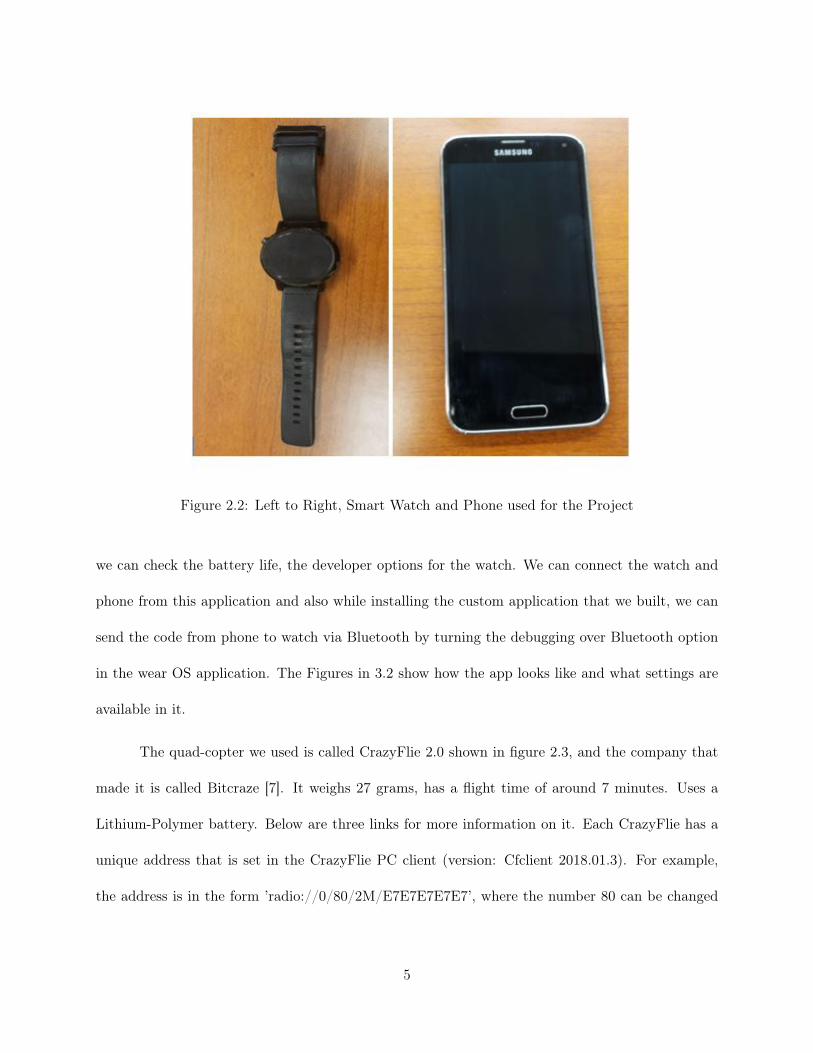
Figure 2.2: Left to Right, Smart Watch and Phone used for the Project
we can check the battery life, the developer options for the watch. We can connect the watch and
phone from this application and also while installing the custom application that we built, we can
send the code from phone to watch via Bluetooth by turning the debugging over Bluetooth option
in the wear OS application. The Figures in 3.2 show how the app looks like and what settings are
available in it.
The quad-copter we used is called CrazyFlie 2.0 shown in figure 2.3, and the company that
made it is called Bitcraze [7]. It weighs 27 grams, has a flight time of around 7 minutes. Uses a
Lithium-Polymer battery. Below are three links for more information on it. Each CrazyFlie has a
unique address that is set in the CrazyFlie PC client (version: Cfclient 2018.01.3). For example,
the address is in the form ’radio://0/80/2M/E7E7E7E7E7’, where the number 80 can be changed
5
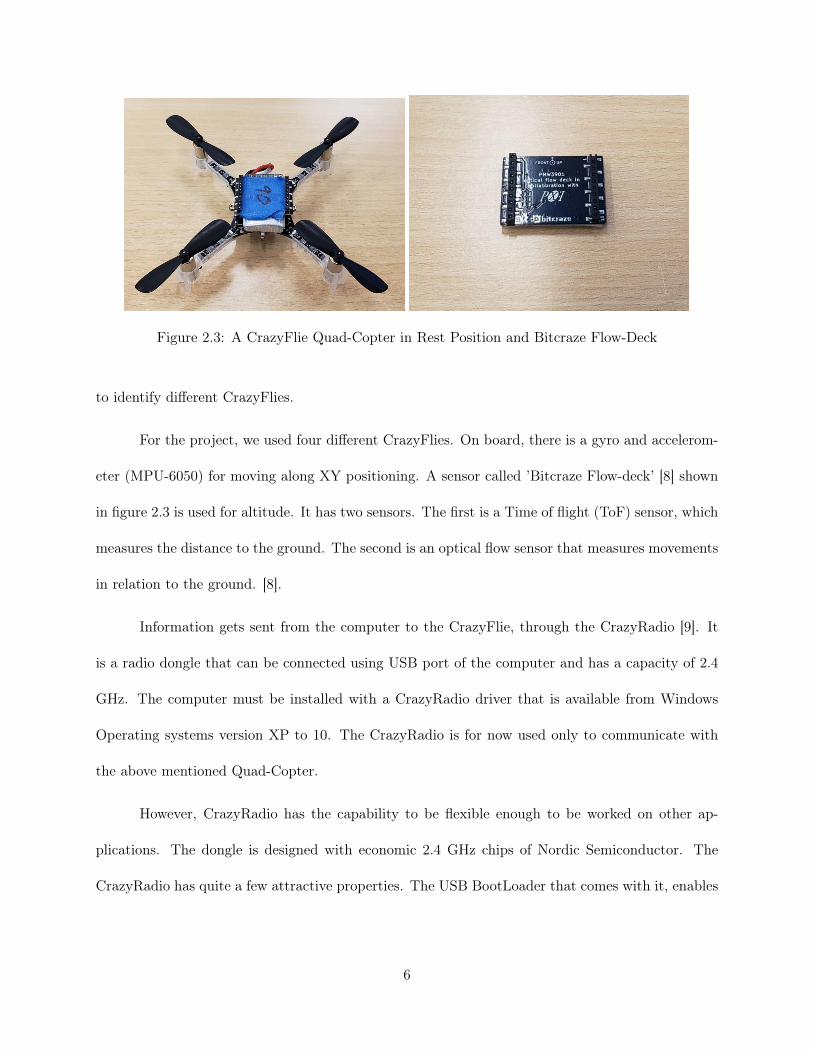
Figure 2.3: A CrazyFlie Quad-Copter in Rest Position and Bitcraze Flow-Deck
to identify different CrazyFlies.
For the project, we used four different CrazyFlies. On board, there is a gyro and accelerom-
eter (MPU-6050) for moving along XY positioning. A sensor called ’Bitcraze Flow-deck’ [8] shown
in figure 2.3 is used for altitude. It has two sensors. The first is a Time of flight (ToF) sensor, which
measures the distance to the ground. The second is an optical flow sensor that measures movements
in relation to the ground. [8].
Information gets sent from the computer to the CrazyFlie, through the CrazyRadio [9]. It
is a radio dongle that can be connected using USB port of the computer and has a capacity of 2.4
GHz. The computer must be installed with a CrazyRadio driver that is available from Windows
Operating systems version XP to 10. The CrazyRadio is for now used only to communicate with
the above mentioned Quad-Copter.
However, CrazyRadio has the capability to be flexible enough to be worked on other ap-
plications. The dongle is designed with economic 2.4 GHz chips of Nordic Semiconductor. The
CrazyRadio has quite a few attractive properties. The USB BootLoader that comes with it, enables
6

Figure 2.4: A CrazyRadio with a USB Dongle Property.
Table 2.1: Devices Used
Sno. Device Name1 Wearable Smart Watch with Android support Moto 3602 Smart-phone with Android Support Samsung S63 Computer with Drivers Installed Acer Predator4 Dongle that communicates with Drones CrazyRadio5 Single or Multiple quad-copters CrazyFlie
upgrades with USB cable. The application can be made a stand-alone one if paired with an expan-
sion header. It has a range of 1 kilometer which means it can send signals to drones which are as far
as one kilometer. The figure, 2.4 shows that CrazyRadio that has been used for the project. The
Dongle connects to the PC over USB and sends signals to the quad-copters. The table 2.1 shows
the list of devices we had for this project.
7

CHAPTER 3: COMMUNICATION AMONG DEVICES
The whole project is designed to be wireless. Hence, the communication among the devices
has also been set up to be wireless.
3.1 Using Bluetooth: Watch to Phone
The watch communicates with the phone using the Bluetooth connection that is established
when the watch gets paired with the phone. It uses this connection to send and receive messages,
data and even syncing the data it has. As discussed in 2, the watch can only pair with one phone at
a time. This is because the watch is connected to the phone via Bluetooth which has a master and
slave system, the phone being the master Bluetooth device. The master device would be having
many slaves but the slave device has only one master device at a time.
Figure 3.1: Watch Sending Message to Phone via Bluetooth
8

Figure 3.2: Wear OS Application Home Screen and Settings Screen (Left to Right)
However, while the master device is connected to one slave device, it can communicate
only with that particular slave device. The wearable device which we have has a Bluetooth 4.0
version embedded in it. Additional research on how Bluetooth works in wearable devices and their
applications have been conducted in [10].
As represented in figure 3.1, the watch connects with the phone. This is done using the
application called Wear OS. This application is available for all android phones and is free to
download. The figure 3.2 shows the screenshots of the wear OS application. The first screen shows
how the home screen after connecting to the watch. The second screen shows the settings of the
watch which could be controlled over the phone. Enabling the last option, "Debugging Bluetooth",
enables the app to be installed over Bluetooth.
9

Figure 3.3: Phone and PC Communicating over WiFi
Once the application is installed, we wanted a system in which as soon as the user makes a
movement, the device must be able to immediately take the action and send it to the phone. For
this, we use Bluetooth as specified. The watch checks its gyro scope’s values and determines the
movement of the hand i.e., left or right or up or down. Then the watch sends this information as
a message using the Bluetooth channel that it has already established. The watch and phone use
"MessageAPI" API to send and receive messages.
3.2 Socket Programming: Phone to Computer
Now as the phone’s Bluetooth has already been connected to the watch, the phone can no
longer use the Bluetooth port to use for communication. In case, it wishes to use it, the phone’s
operating system has to switch the Bluetooth connection between the devices. In order to avoid
that, we use socket programming. Detailed elaboration as in [11] gives more insight into this. A
socket is a two-way communication’s endpoint for two different programs that run on a network.
These programs can be on the same system or a different system. Socket Programming is a technique
where the devices can communicate among themselves over the wireless network or internet using
10

Figure 3.4: Computer Sending Signals to Drone via CrazyRadio
these sockets. The service need not be available the two devices have to be known about each others
IP addresses. This would be done by knowing the network location. For this project, we record the
network location manually. A socket has an identifier called "Port number" which enables the TCP
layer to recognize the destination and sends the data to it.
In the current setup, in order to enable the socket programming, we need to have the phone
and the PC on the same network. To achieve that, we have set up the phone and the PC to be on
the Wireless network, WiFi. Shown in 3.3, the phone sends the signals to the computer over WiFi
by using "Socket.Net" library in Java.
3.3 CrazyRadio: Computer to Quad-Copters
This part would be flawlessly handled by the CrazyRadio of which we discussed in 2.
CrazyRadio can be connected to PC as an add-on hardware using the USB port. Now it acts
similar to a WiFi dongle. This instead connects to the drones. As shown in figure 3.4, the PC has
a dongle connected to it to communicate with the drone.
11

Figure 3.5: Computer Sending Signals to Multiple Drones over CrazyRadio
Table 3.1: Communication Channels Used
Sno. Scenario Communication Channel1 Watch to Phone Bluetooth2 Phone to Computer Socket Programming3 Computer to Drone(s) Dongle a.k.a CrazyRadio
This CrazyRadio would also keep track of the drones with the help of their unique IDs. It
also coordinates the signals while controlling multiple drones. As shown in figure 3.5, even if there
are multiple drones, a single CrazyRadio is sufficient to communicate with all of them. This step
uses Python code which includes the Unique ID of the drones given in it. The CrazyRadio uses this
ID to register them into the working model and sends signals to each one. It would send one signal
at a time. Which means all four drones wouldn’t be getting signal at the same time. There would
be a gap of a millisecond or two in sending signal one by one. Hence the total communication could
be broke down into different parts as shown in Table 3.1
12

CHAPTER 4: CODING APPROACH
In order to make the application work as per the requirements, we need to deploy a piece of
code into them. The platforms we chose and the programming languages we used for this project
are all quite flexible and open source. This enabled us to easily modify the code and rebuild a
working system according to our requirements.
4.1 Android Application for Watch and Phone
As mentioned and discussed previously, an application has been developed for both watch
and phone that establishes a coordination among them. Let us first consider looking at the wear’s
application. We have used a library called "android.hardware" which allows us to use the hardware
resources that the android device has. The Classes used and their uses are stated in table 4.1. In
order to use this, we need to specify the "<uses-feature>" tag in the manifest file of the project.
Table 4.1: Libraries to Use Sensors
Sno. Classes Description1 Sensor Class that represents sensors2 Sensor Event Class that represents a sensor and also holds
information about sensors (type, data, accuracy etc)3 Sensor Manager Gives Access to use device’s sensors4 SensorEventListener An interface that Receives alerts from Sensor Manager
on new Sensor Data or the sensor’s data change.
13

Figure 4.1: Code to Initialize and Use Gyroscope Sensor
Once the classes are used, we can use their methods to access the sensor’s data. The sensor
class could be used to register the gyroscope sensor which we intend to use. In figure 4.1, we can
see that the sensor class is used to get the gyroscope sensor, where the sensor manager has helped
to get the gyroscope sensor registered to the current usage.
As we have the sensor now, we need to get an action listener which uses the sensor manager
to get notifications whenever there is a change in the sensor’s data. The listener is an interface
which implements methods that constantly look for any notifications, in specific, events. Sensor
Manager gives a notification whenever there is a change in the form of a SensorEvent object which
has all the information about the sensor.
The listener interface takes this SensorEvent and lets the user program it according to his
wish. Since the listener is an event, it has methods that have to be overridden in order to use
them. The first method is "onSensorChanged" method. This method is called in when the listener
receives an alert with SensorEvent as input. This means that the sensor’s state has been changed.
14

Figure 4.2: Handling Gyroscope Sensor’s Data
The second method is "onAccuracyChanged" which has a sensor object and int as input which
is triggered when the registered sensor’s accuracy has been changed. We haven’t used the second
method in our project.
The figure 4.2 shows the usage of the "onSensorChanged" method in reading the gyroscope
sensor’s data and the SensorEvent object has been handled as required. The SensorEvent object
also has the properties of the sensor which could be used while handling the sensor event and using
the sensor’s properties. The property ".values" returns all the properties of the sensor that is in
use. In the current scenario, the gyroscope has the properties of "x-axis", "y-axis" and "z-axis".
These values change when the sensor’s direction, orientation is changed and hold a decimal value.
15

Figure 4.3: Sensor Data Collection Control
The wearable code also extends a WearableActivity, an abstract class which helps keeps track
of the registering and de-registering the sensor. This makes sure that the algorithm doesn’t run when
it is not required to. It provides the access to "onResume" and "onPause" classes when extended.
"onResume" is executed when the sensor is to run and "onPause" when the sensor doesn’t have to.
The implementation is given in figure 4.3.
Table 4.2: Libraries to Send Data from Watch to Phone - Wearable.
Sno. Classes and Interfaces Description1 Capability client API to learn the capabilities by a node on network2 Capability Info Provides information about capability on network3 Node Gives information about a node on network4 Wearable API that gives access to Wear Platform in Android
Table 4.3: Libraries to Send Data from Watch to Phone - Tasks.
Sno. Classes and Interfaces Description1 Task Shows an asynchronous action2 Tasks A utility for the Task object3 OnFailureListener This listener is called when a failure occurs4 OnSuccessListener This listener is called when the execution is successful
16

Figure 4.4: Searching for Best Node and Updating Capability
Now that we have a way to get the sensor’s data and the method to capture it, we need to send
this to the phone over Bluetooth. To achieve this, we use "MessageClient" and "CapabilityClient".
We used "Wearable" and "Task" library for this. Wearable library deals with the communication
between the phone and the watch where Task library deals with maintaining the message or data
in a synchronized way, in this case, immediately.
All these are available in "com.google.android.gms.wearable" and "google.android.gms.taskS"
library. The table 4.2 shows the classes of wearable and uses while the table 4.3 shows the same of
classes of Tasks. The watch has a capability that has to be entered in the values. The watch when
requested to transfer the data, looks for the all the nodes nearby that have the same capability.
Here the nodes are the processes running on one phone or different phones. This can be
done by implementing the functions as in figure 4.5. We have to also specify that the phone to uses
this capability by specifying the same in the values field. This way the phone’s application registers
itself into the list of devices with the capability.
17

Figure 4.5: Setting-up the Transfer to the Best Node.
This best node that has the capability can be used to set up the transfer. Here, the Capa-
bilityClient and Wearable are used to get the information and establish the connection between the
phone with the specified capability and the Wearable device i.e, the watch. The Tasks class is used
to make the process wait when there is no node with such capability.
We can now create a class to Transfer the data from watch to phone as shown in 4.6. In
this class, the transfer has to be done immediately when the sensor data has been changed. Hence
we would be using the AsyncTask Interface to achieve this. This interface helps us define the tasks
that have to be done in the background. In 4.6 we can also see that the TRANSFER NAME and
TRANSFER PATH are defined as static strings which are none other than the capability name and
the path that helps the phone to cross check if the message that it has received is intended to it or
not. Also, The string TRANSFER ONOFF is the capability for the button that we have to stop or
start recording the sensor data.
18

Figure 4.6: Sending Messages Asynchronously in Background.
The AsyncTask, when implemented, has to have "doInBackground" method which executes
in the background. This method is pretty simple as it takes an object as input and gives an object
as output. So we can be versatile to use any input and get an output. As we are done setting
up, we just need to now request the transfer of data which is done in figure 4.7. We can use the
AsyncTask interface by importing the "android.OS" library. The request transfer method that we
have created would first check if there is a node or not. If there is no node, then the function would
throw an error to the user regarding the same else it would use the Task object to initialize a task.
After initializing the task, we use the Wearable class to obtain the message client. The message
client can be used to send the message to the phone and it takes three inputs. First is the node ID,
which we get from the setup transfer function. The second input is the path which we defined it as
a static string and would help the phone authenticating its message. The third input is the data or
19

Figure 4.7: Method to Send Messages.
the content of the message which we intend to send over the established connection channel. The
second function in 4.7 is to send the messages regarding the sleep state or active state of the sensor.
As now we are done by the code at the watch side, let us look at how these messages have to
received and handled on the phone side. The phone activity would implement the "MessageClient"
interface and use the "OnMessageRecievedListerner". The listener has to be initialized and regis-
tered. The interface needs three methods to be implemented. The first method is "onResume",
which should use the resume method in the parent class. This method lets the listener know when
to start expecting a message. The second method. "onPause" is quite opposite to the "onResume"
method on when it is called. The "onPause" method also overrides the parent’s method and calls
it. This method is executed when the application has no longer need to receive the messages. The
third method is "onMessageRecieve" method. This message is executed when a message is received
20

Figure 4.8: Methods of MessageClient.
by the application. As we can see in figure 4.8, we can see all the three methods being implemented
and being overridden.
While receiving a message, the "onMessageRecieved" function gets a MessageEvent object.
This object has the message data in it. The message data is in the form of bytes which we have to
convert into a string. Then this message is authenticated using the message path property. After
authentication, we can add the custom set of code lines which we want to.
SetSignal is a custom, user-written function which is intended to convert the string that is
extracted from a stream of bytes to a desirable data. For example, if the watch sends the signal
saying "up", the stream of bytes when converted to string would be "up". For the Drone to fly in
the upward direction, we need to send the signal 0. Hence, we used "SetSignal" function to convert
the strings to Drone-understandable signals. Now as we have the signals ready, we need to send
them to the phone. For that, we need to use socket programming. As discussed, we need an IP
address of the device in order to communicate with it over TCP using the port numbers. Hence
21

Figure 4.9: Taking IP Address and Port Number as User Input.
we use the user interface to let the user put in the IP address and port number as in figure 4.9.
We have also added the input for no of Drones are about to be controlled so that the signal can
be sent. The message that has to be sent to the Computer has to be done in the background and
simultaneously. Hence we use a class that implements AsyncTask for this too as we did before. The
"doInBackground" function sends the signal. "DataOutputStream" is an object which sends the
signal as a stream of bytes to the given socket object which has to be created and initialized with
an IP address and a port number. This can be seen in figure 4.10.
4.2 Python for Communicating with the Drones
The computer uses Python code to Control the Drones. This code is in integration with
the CrazyRadio and uses the libraries as in 4.11 . The code is executed in the python shell and
is quite fast and flexible. It has the list of IDs of all the Drones that are possibly about to fly. It
also has the functionalists like a "Run sequence" which executes in a loop, "reset estimator" and
the main function. The reset estimator function handles the parameters of the Drones. Here, we
declare few global variables which are uniform across the program. They are: IP address, Port
22

Figure 4.10: Class Implementing Socket Programming.
Figure 4.11: Libraries for Drone Control.
number, URIs (IDs) of the Drones, Buffer size, which means the largest number of bytes that can
be transferred. This Program uses the Socket and time libraries to handle the data transfer and
asynchronous execution respectively.
The figure 4.12 is the main function of the program where the execution starts. In this
function, we register the socket by creating a socket object using the IP address and the port
number. This socket is then started for listening which means it constantly checks for messages.
This function also implements the "run sequence" and "reset estimator" to be run constantly. The
23

Figure 4.12: Main Function of the Python Program.
Figure 4.13: Sending Signals to Drones According the Message Received.
"run sequence" function converts the received messages into the signals and sends them to the
Drones. In the figure 4.13, the half implementation of the run sequence function. It opens a
connection with the socket we initialized and started receiving the messages at the beginning and
closes the connection at the end of the function. Also, it can be observed the connection object also
receives data in the form of bytes which is later converted into integers. After the conversion, these
integers are used to send signals to the Drone through the dongle.
24

CHAPTER 5: ANALYSIS
There are many interesting points that this project has given out. This chapter discusses
these points and draws out the deductions from them and the outcomes of the project that we
constructed in 2 and 4. These deductions have been applied to overcome the real-time challenges
that are faced.
The first deduction that was made is about the properties of the gyroscope. As we see that
the gyroscope’s properties have been used in the code which is represented in figure 4.2. The code
uses the property called "values" which as discussed contains the properties of the sensor. The
properties are an array of these values object. For the gyroscope, we have the "x-axis" value of the
sensor in the zeroth index of the "values" array. The value can be access using the statement as
shown in the code line, 5.1.
sensor.values[index] (5.1)
Table 5.1: Sensor Value Indices in the Array.
Property Index Usage Return Value Unit of MeasureX-axis 0 sensor.values[0] float rad/sY-axis 1 sensor.values[1] float rad/sZ-axis 2 sensor.values[2] float rad/s
25

To use the "y-axis" and "z-axis", the indexes would be 1 and 2 respectively. Hence, as a
whole, the usage statements would be as shown in the table 5.1. The values that are returned by
these statements are integer values, to be specific, they a signed floating point values which are
decimal numbers that might be positive or negative.
Another deduction we can be made on this sensor property is that the z-axis value could
be used to track the horizontal movement of the wearer’s hand. Which means the z-axis property
would help us to track if the user has moved their hand to left or right based on its value that it
has returned when used the "values" feature on it.
The verdict is that when the hand is moved left, the z-axis reading of the sensor readings is
positive. When the hand is moved to the right, the z-axis readings give negative values. Similar
to the y-axis readings. They are negative when the hands have moved upward and the values are
positive when the hand is moved downward. If the user would make a movement parallel to the
ground, but perpendicular to him, which depicts the motion of "punching", the x-axis would be
helpful in tracking this motion. This project didn’t require such a movement as we haven’t planned
to use it in the current setting. Hence the x-axis behavior is yet to be studied.
The sensor senses when there is a movement in the hand. It would record even the slightest
movement in it. For example, the user has worn a watch and is standing with the hand raised
perpendicular to him, the sensor values would still change as it is not a practically a rest position.
Human hand makes a very slight movement even when the person tries to stay still in a practical
situation.
SensorManager.SENSOR_DELAY_NORMAL (5.2)
26

Table 5.2: Sensor Delay Options.
S.no Value Name Delay Time in ms Usage1 SENSOR_DELAY_FASTEST 0 gets value as soon as possible2 SENSOR_DELAY_GAME 1 Suitable for Games3 SENSOR_DELAY_UI 2 Suitable for User Interface4 SENSOR_DELAY_NORMAL 3 Suitable for Orientation changes
In order to control the sensitivity of this gesture recognition, with the code line as in the
code line 5.2. There are three values of sensor delay which are given in table 5.2. The sensitivity
can be controlled by implementing the necessary value to the sensor manager and it would capture
the values with that delay. Since SENSOR_DELAY_NORMAL is the best for this case, it has
been used to adjust the sensitivity.
This delay can be further handled in the code by giving certain thresholds when the algorithm
has to process. For example, as we see in figure 4.2, the code only handles when the sensor values
that are greater than 2 and less than -2. These values are reached only when a user makes a complete
left or right rotation respectively. The Drones are sensitive to the immediate signals. Which draws
a situation in where the user could make an accidental minute left or right movement which the
sensor reads and the project would send a signal to the Drones. But, The Drones need a little delay
between the signals else they would crash. These accidental or unintentional movements might
cause these crashes in order to avoid that, we need to handle the sensitivity of the sensors.
The User Interface has been designed to be simple, user-friendly as well as aesthetic. The
color choices and backgrounds have been selected keeping in mind that this project would be used
or demonstrated in an area with brighter conditions. The functionality that has been included is
intended to make the process simpler for the user.
27
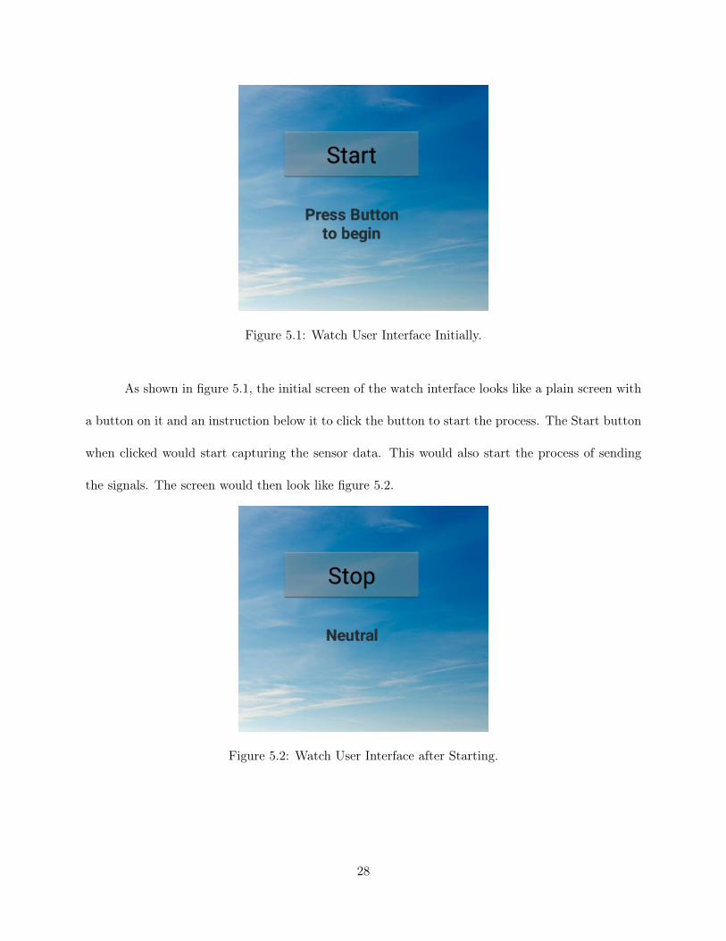
Figure 5.1: Watch User Interface Initially.
As shown in figure 5.1, the initial screen of the watch interface looks like a plain screen with
a button on it and an instruction below it to click the button to start the process. The Start button
when clicked would start capturing the sensor data. This would also start the process of sending
the signals. The screen would then look like figure 5.2.
Figure 5.2: Watch User Interface after Starting.
28

Once the start button is clicked, the button changes to a "stop button" and the text below
would also change according to the movement. As it is shown in figure 5.2, the start button has
now been changed to stop which means that the process has started and the user could click on the
stop button whenever he wishes to stop the capture.
Clicking the stop button would also send a signal which would make the Drones land safely
to the ground. In this case, sending the signal, "8" to the Drones makes them land safely on the
ground. This is a more convenient way for the user as he only needs to click a button on the watch
instead of the traditional method of force stopping the python program.
Figure 5.3: Watch User Interface While Capturing.
The Text below the button would change according to the process. At first, it is an instruction
but later, after turning the capture on, this text shows the visual feedback of the movements the
user has made. This enables the cross-checking and immediate feedback facilities to the user. This
text would be left, right, up, down or neutral which are the textual representation of the user’s hand
movement as shown in figure 5.3.
29

Figure 5.4: User Interface of Phone Initially.
Since we have seen the watch interface and how it works, we can now jump onto the phone’s
interface and its working. The figure 5.4 shows the initial screen of the application. It has the input
for IP address, Port number and the Number of Drones. Since the IP address and Port number
are not always constant and rather tend to change with the change in the network, this would be a
better way for the user to enter them in runtime than making changes in the code.
The IP address field is intended to take the IP address of the computer which is on the
same network. The Port number field accepts the port number for the socket communications. The
number of Drones field takes a single integer which represents the count of the Drones that is taken
for the current setting of the project. These fields when entered and hit submit, the values get
stored to the variables as we have seen in the figure 4.10. In the figure5.5, see a sample input being
given to the application
30

Figure 5.5: User Interface of Phone after Data Entry.
The submit button calls a function internally that binds the entries in the user interface to
the underlying variables. This is basically the first step of our project set up. Once we have all the
devices charged and turned on, the computer’s IP address has to be determined. This IP address
has to be given in this application as an input.
At the computer side, in the python program, we must update the IP address and assign a
port number which can be a combination of any 4 random digits, ranging from 0001 to 9999. After
this, we need to register the unique IDs of the Drones into the python program. After that, we can
start the capture by clicking on the start button of the watch. After Clicking on "Submit" button,
the user would be given a toast message i.e., a pop-up message on the screen saying, "Connection
Established" giving them a feedback that the connect has been established successfully and the
system is ready for a data capture.
31

Figure 5.6: User Interface of Phone While Capturing.
Once the start button is clicked on the watch, the text against the "Sensor Status" would
change to start. It would say "Stopped" if the stop button is clicked. But initially, it would be
"OFF". The text against the "Movement" label shows that same feedback as of the watch. It stays
"Neutral" when the capture is not running, but when the capture has started, it would show the
same value which is on the watch that represents the captured hand movement. This can be seen
in figure 5.6 where the sensor has been started and the user has moved down which could be seen
on the screen.
32

CHAPTER 6: LIMITATIONS
Though the sensitivity levels are checked and all other care is taken, this system has some
limitations which have to be addressed in order to get a foolproof system.
6.1 Gestures Differ
There is always a possibility that a movement may be done totally different by another
person. A person may move their arm just from their elbow when someone asks them to move their
arm upward while some might move his or her whole arm until the shoulder to do the same. In
these cases, the readings of the sensors, differ a lot. Some might move their arm pretty quickly while
someone might take a while to do it. All these gestures need to be understood by the algorithm
which needs a lot of data to learn from.
6.2 Drone Drift
The Drones have sometimes experienced a drift while positioning themselves. This has been
added as they would avoid colliding with one another and would move farther when there is an
obstacle but this sometimes causes a problem when the user actually wants the two Drones to
be nearer to one another. Also if these Drones are used in a windy environment they would be
vulnerable to loss and damage. They should always be used in a supervised and a controlled
condition which is under a Drone protector nets and a drift detector.
33

6.3 Maintaining Battery Life
The current setup needs four devices to be charged and maintained. The watch has to be
kept turned on all the time while the project is being carried out and which would consume a lot of
battery. Turning the screen off would cause the application to go sleep and we would not be able
to get the reading. The same case with the phone and the computer. Hence the devices should be
charged and maintained throughout the process. The Drones also have evidently lesser charging
life. They have the flight time of seven minutes and the batteries have to be replaced when they
run out of power.
34

CHAPTER 7: FUTURE WORK
The future works of this project may include the following ideas.
7.1 Adding More Gestures for More Features
A Drone may have many features. Some might have a camera access while some may have
a GPS enabled on them. We can extend the algorithm in such a way that a gesture made by the
user can control these abilities. Like a wave may make the camera turn on. We can also make
the Drones to form a certain shape with the gestures. For example, consider 5 Drones have been
taken and four of them (Drone numbers, 1,2,3,4) have been arranged as a square and the fifth one
is placed at the center. When the user makes a gesture, say, two consecutive upward movements
quickly, the Drones 1,2,3,4 move one step upward and the Drone 5 moves two steps upward. This
forms a pyramid structure of Drones. Complex applications of this can be used in many ways.
7.2 Implementing Drones to Pick Weights
The given model when implemented with Drones of higher capability which can carry larger
weights, can be used by people with challenges and difficulty in lifting weights to easily relocate
object around them. When studied the sensitivity of the sensors with people having different health
conditions with difficulty in movement, and the sensors are tuned to it, the algorithm can be used to
enable them in an easy relocation of objects. This can be implemented in large scale by implementing
the algorithm over micro-integrated chips to the wheels of trolley bags or trolleys carrying goods
35

so that human effort could be reduced in shifting them as one may be able to do it with a simple
gesture. Another application of this technique would be to achieve a complex task. For example,
an object has to placed on a high altitude place, we can use Drones to do that.
36

CHAPTER 8: CONCLUSION
This project is a demonstration of how a simple setup can be made to use a gesture recognition
pattern to apply in a real-world scenario. All the equipment that is used in this experiment is so
lightweight and economic. They are also flexible and easily personalized. Usually, materials that
are economic do not come with a good flexibility of customization. But with the implementation of
algorithms in a good way, makes this task easier. The algorithm need not be complex or use extra
libraries and utilities to work. For this project, we have considered using the existing resources to
the fullest the achieve the output.
Gesture recognition as it evolves, would bring down new challenges and new possibilities as
one goes on exploring it. Once all these cases are served and we know how to deal with them, we
can develop a foolproof system and could be used in many applications. There was development in
which the devices were made wireless in every possible way. Now the systems that are hands-free
are more evolving as they are less stressful and easy to handle.
As discussed, the applications could be very large and could be used for noble causes and
in helping challenged individuals. This could also be a next big thing in the security and surveil-
lance systems. Likewise, when used with care and security, these systems could be having a wide
application. Although, these systems are highly risked towards hacking and unauthorized controls.
Once evolved, these systems would be highly relied on. At that stage, once hacked, the hacker
can have control over a major part of the victims routine. Avoiding such complications would help
37

us make the most effective usage of the gesture recognition. Recent times, machine learning and
Artificial Intelligence have been popular and we could see the application in every other application.
Researches being conducted which would include the gesture recognition with machine learning and
Artificial intelligence in which the habits and mannerisms could be captured by the system and
could be reproduced by the Artificial Intelligence and could recreate them. Projects like the current
one would be stepping stones for the future more stabilized in which the outcomes could be used
and recreated to achieve a similar or more complex task.
38

REFERENCES
[1] F. Liu, Y. Wang, and H. Ma. Gesture recognition with wearable 9-axis sensors. In 2017 IEEE
International Conference on Communications (ICC), pages 1–6, May 2017.
[2] IntelliJ’. https://developer.android.com/studio/intro/, 2018.
[3] IntelliJ’. https://developer.android.com/, 2018.
[4] Y. Yu, X. Wang, Z. Zhong, and Y. Zhang. Ros-based uav control using hand gesture recognition.
In 2017 29th Chinese Control And Decision Conference (CCDC), pages 6795–6799, May 2017.
[5] H. Tamura and Y. Tomikawa. Three-axes vibratory gyrosensor. In 2000 IEEE Ultrasonics
Symposium. Proceedings. An International Symposium (Cat. No.00CH37121), volume 1, pages
889–892 vol.1, Oct 2000.
[6] V. Apostolyuk. Whole angle force rebalance control for coriolis vibratory gyroscopes. In 2014
IEEE 3rd International Conference on Methods and Systems of Navigation and Motion Control
(MSNMC), pages 59–61, Oct 2014.
[7] Bitcraze. https://www.bitcraze.io/, 2018.
[8] Bitcraze. https://wiki.bitcraze.io/projects:crazyflie2:expansionboards:flow, 2018.
[9] Bitcraze. https://wiki.bitcraze.io/projects:crazyradio:index, 2018.
39

[10] T. Jo, Y. You, H. Choi, and H. Kim. A bluetooth-upnp bridge for the wearable computing
environment. IEEE Transactions on Consumer Electronics, 54(3):1200–1205, August 2008.
[11] M. Xue and C. Zhu. The socket programming and software design for communication based
on client/server. In 2009 Pacific-Asia Conference on Circuits, Communications and Systems,
pages 775–777, May 2009.
40

ABOUT THE AUTHOR
Venkata Sireesha Dadi received her Bachelor of Technology degree in Computer Science
and Engineering from Jawaharlal Nehru Technological University - Kakinada, India in 2015. She
worked as a software developer at Infosys - Hyderabad, India for 2 years and been awarded as
"Best Utilizer" and "High Performer" titles for her outstanding works. In Fall 2017, she has joined
University of South Florida - Tampa to pursue her Master with thesis degree under the supervision
of Dr. Sriram Chellappan. Sireesha received her MS Degree in Fall 2018. Her work has impressed
many professors from the Department of computer science and engineering and Department of
mechanical engineering at the University of South Florida.