dÜrr ndt cr workshop iso 17636-2 weld test with x …œrr ndt cr workshop iso 17636-2 weld test...
TRANSCRIPT

Recommended Techniques
» There are many possible techniques for making good radiographs
using CR
» Following a defined procedure will simplify technique
development and shorten the time to a good image
» As an example, we will step through the process using
ISO 17636-2 standard
DÜRR NDT GmbH & Co. KG 2 September 6, 2017

Example
We want to test a steel weld plate of 18 mm thickness according the ISO 17636-2 Class B standard with X-ray
DÜRR NDT GmbH & Co. KG 3 September 6, 2017
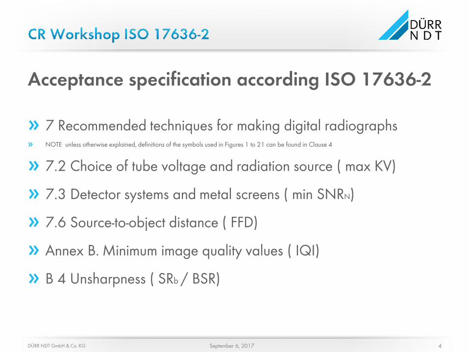
Acceptance specification according ISO 17636-2
» 7 Recommended techniques for making digital radiographs » NOTE unless otherwise explained, definitions of the symbols used in Figures 1 to 21 can be found in Clause 4
» 7.2 Choice of tube voltage and radiation source ( max KV)
» 7.3 Detector systems and metal screens ( min SNRN)
» 7.6 Source-to-object distance ( FFD)
» Annex B. Minimum image quality values ( IQI)
» B 4 Unsharpness ( SRb / BSR)
DÜRR NDT GmbH & Co. KG 4 September 6, 2017

Step 1 – Physical Technique
» There are many different radiographic techniques:
• Single and double wall exposures
• Elliptical exposures
• Perpendicular technique
• Techniques for flat or curved samples
DÜRR NDT GmbH & Co. KG 5 September 6, 2017

7 Recommended techniques for making digital radiographs
In the case of a flat plate, the recommended technique is perpendicular, with the radiation source in front of the object and the imaging plate on the opposite side
DÜRR NDT GmbH & Co. KG 6 September 6, 2017

Step 2 – Maximum X-ray Voltage
» There are recommended maximum X-ray voltages for different materials and thicknesses
» Using the following table, we can determine the maximum X-ray KV
» For Imaging Plates (IP’s) with high structure noise (coarse grained) a reduction in Kv of about 20% is recommended
» Fine-grained IP’s can use the highest KV
DÜRR NDT GmbH & Co. KG 7 September 6, 2017

7.2 Choice of tube voltage and radiation source
Max. 260 KV
WD 18 mm
1) We have a thickness of 18 mm, so we go up to curve 2 (steel)
2) We draw a line from the point of intersection to the left, to the KV
DÜRR NDT GmbH & Co. KG 8 September 6, 2017

Signal-to-Noise Ratio normalized (SNRN)
Inspection class is determined by the normalized Signal-to-Noise Ratio (SNRN)
• SRNN takes into account the system Basic Spatial Resolution (SRB)
• Class A inspections are lower quality
• Class B inspections demand higher SNR and have more stringent image quality requirements
• SNR measurements must be made using specific techniques and have defined limits
Metal screens
• If metal screens are used, insure that there is intimate contact between the Imaging Plate (IP) and the metal screen.
• IP‘s are very sentitive to low energy backscatter, which must be controlled
• It is recommended that a Fe or Cu screen be used directly behind the IP, between the IP and any back lead screens
Step 3 – Detector systems and metal screens
DÜRR NDT GmbH & Co. KG 9 September 6, 2017

7.3 Detector systems and metal screens
The Minimum SNRN
We need is :100 ?
If you measure the SNRN in the HAZ*, you must Multiply by 1.4
100 SNRN X 1.4 = 140 SNRN
We need a minimum
SNRN of 140
We are working with 260 KV under 50 mm thicknes for Class B
* HAZ = Heat Affected Zone
DÜRR NDT GmbH & Co. KG 10 September 6, 2017

Step 4 - Source-to-object distance
DÜRR NDT GmbH & Co. KG 11 September 6, 2017

7.6 Source-to-object distance
1) Focal spot size of this tube is d = 1 mm
2) The object-to-detector distance b for this test arrangement (from Figure 1) is the same as the plate thickness (WD =18mm), so b = 18 mm
The Minimum source-to-object distance for this example for Class B = 105 mm
• Source-to-object distance can be most simply determined by using the nomogram included in the inspection standard
• For our example we will assume:
– The focal spot of the X-ray tube is 1mm
– The plate is in direct contact with the imaging plate, thus the object-to-detector distance is the same as the plate thickness – 18mm
DÜRR NDT GmbH & Co. KG 12 September 6, 2017

Step 5 – Image Quality Measurements
» Image Quality Indicators (IQI’S)
• Decide on the type of IQI that will be used
− Wire IQI
− Step and hole IQI
• Decide whether the IQI is to be placed on the source side or the detector side of the object
• Determine the correct IQI for the Inspection Class and the object thickness from the table in the relevant standard
DÜRR NDT GmbH & Co. KG 13 September 6, 2017

Annex B. Minimum image quality values ( IQI)
This table is for wire IQI’s placed on the source side of the object when using the single-wall technique
Since our plate is 18mm thick, we need to see wire W13
DÜRR NDT GmbH & Co. KG 14 September 6, 2017

Step 6 – Unsharpness
» Image unsharpness is a measure of the loss of definition caused by geometric factors
» It is caused because the radiation emitter is not a true point source
» The factors affecting unsharpness are source focal spot size, source-to-object distance and object-to-detector distance
DÜRR NDT GmbH & Co. KG 15 September 6, 2017

Annex B. Unsharpness For this plate of 18 mm. we go to “Penetrated thickness” 12 <w>40 to see which Basic Spatial Resolution (SRb) we need. For our example we need a SRb better than 100 µm Dn refers to the wire pair that needs to be resolved, in this case D10
DÜRR NDT GmbH & Co. KG 16 September 6, 2017

Step 7 – Determine Basic Spatial Resolution
» A reference image is required to measure the Basic Spatial resolution (SRb)
• The inspection target is not used - the penetrameter shall be placed directly on the IP
• The source-to-detector distance shall be 100cm ± 5cm
• The mean gray level in the image shall be >50% of the system maximum
• The measured SNR in the image shall be >70 for high-resolution systems
DÜRR NDT GmbH & Co. KG 17 September 6, 2017

Unsharpness and Resolution
» Unsharpness can be calculated from the Basic Spatial Resolution (SRb)
» SRb can be measured using the EN 462-5 duplex wire penetrameter according to ISO 19232-5
» The Dn in the previous table refers to the duplex wire pair on the IQI
DÜRR NDT GmbH & Co. KG 18 September 6, 2017

Basic Spatial Resolution Measurement » Basic spatial resolution is measured by evaluating the grey level dip in a line
profile drawn across the duplex IQI wire pairs
» A dip of >20% in grey level indicates that the wire pair is resolved
» This determines the SRb of the system
DÜRR NDT GmbH & Co. KG 19 September 6, 2017

Step 8 – Choosing the Exposure Parameters
» To recap the acceptance specifications:
• X-ray max voltage = 260 KV
• Minimum SNRN must be 140 measured in the heat affected zone
• No lead screens are necessary
• FFD should be 105mm minimum
• We must see IQI wire 13
• We need a SRb of 100 µm
DÜRR NDT GmbH & Co. KG 20 September 6, 2017

But we always try to be better than the minimum, so: » X-ray max voltage = 260 KV » Minimum SNRN must be 140 measured in the heat affected zone » No lead screens are necessary » FFD will be 500mm (this may affect the shot time) » We must see IQI wire 13 » We will aim for a SRb of 80 µm
DÜRR NDT GmbH & Co. KG 21 September 6, 2017
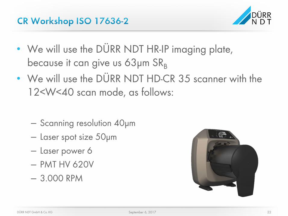
• We will use the DÜRR NDT HR-IP imaging plate, because it can give us 63μm SRB
• We will use the DÜRR NDT HD-CR 35 scanner with the 12<W<40 scan mode, as follows:
– Scanning resolution 40μm – Laser spot size 50μm – Laser power 6 – PMT HV 620V – 3.000 RPM
DÜRR NDT GmbH & Co. KG 22 September 6, 2017