dse112
DESCRIPTION
DSE112TRANSCRIPT

M.Sc. Information Technology
(DISTANCE MODE)
DSE 112
Software Engineering
I SEMESTER
COURSE MATERIAL
Centre for Distance Education Anna University Chennai
Chennai – 600 025

Author
Dr. G.V. Uma Assistant Professor
Department of Computer Science and Engineering Anna University Chennai
Chennai – 600 025
Reviewer
Dr. K. M. Mehata Professor
Department of Computer Science and Engineering Anna University Chennai
Chennai – 600 025
Editorial Board
Dr. C. Chellappan Professor Department of Computer Science and Engineering Anna University Chennai Chennai – 600 025
Dr. T.V. Geetha Professor Department of Computer Science and Engineering Anna University Chennai Chennai – 600 025
Dr. H. Peeru Mohamed Professor
Department of Management Studies Anna University Chennai
Chennai – 600 025
Copyrights Reserved (For Private Circulation only)


ACKNOWLEDGEMENT The Author Dr.G.V.Uma, Assistant Professor, Department of Computer Science &
Engineering, College of Engineering, Anna University, Chennai – 600 025, extends heart
felt thanks and gratitude to the Director, Distance Education, Anna Univesity, Chennai
and the Deputy Director, M.Sc Software Engineering, for the opportunity given to
prepare the Course Material for Software Engineering.
I author has drawn inputs from Several Sources for the preparation of this Course
Material, to meet the requirements of the syllabus. The author gratefully acknowledge
the following sources:
Software Engineering A Practitioner’s Approach, By Roger. S.Pressman, Mc
Graw Hill International 6th edition, 2005.
www. OO design.com
www. Sqa.net
www. Softwareqatest.com
www. Sce. Carleton. Ca / faculty / chinneck / po / Chapter 11. pdf
www. Cs.Umd.edu / ~vibha
An integrated approach to software Engineering, By Pankaj Jalote, Second
edition, Springer verlag 1997.
software Engineering, By Ian Sommerville, 6th edition, Pearson education, 2000.
Dr. G.V. UMA
Assistant Professor Department of Computer Science & Engineering
College of Engineering Anna Univesity, Chennai – 25.


DSE 112 SOFTWARE ENGINEERING
UNIT I
Introduction – The Software problem – Software Engineering Problem – Software Engineering Approach – Summary – Software Processes – Characteristics of a Software Process – Software Development Process – Project Management Process – Software Configuration Management Process – Process Management Process – Summary. UNIT II
Software Requirements Analysis and Specification – Software Requirements – Problem Analysis – Requirements Specification – Validation – Metrics – Summary. UNIT III
Planning a Software Project – Cost Estimation – Project Scheduling – Staffing and Personnel Planning – Software configuration Management Plans – Quality Assurance Plans – Project Monitoring Plans – Risk Management – Summary. UNIT IV
Function-oriented Design – Design Principles – Module-Level Concepts – Design Notation and Specification – Structured Design – Methodology – Verification – Metrics – Summary. Detailed Design – Module specifications – Detailed Design – Verification – Metrics – Summary. UNIT V
Coding – Programming Practice – Top-down and Bottom-up - structured programming – Information Hiding – Programming style – Internal Documentation Verification – Code Reading – Static Analysis – Symbolic Execution – Code Inspection or Reviews – Unit Testing – Metrics – Summary Testing – Fundamentals – Functional Testing versus structural Testing – Metrics – Reliability Estimation – Basic concepts and Definitions – Summary. TEXT BOOK
1. Pankaj Jalote, “An Integrated Approach to Software Engineering”, Narosa Publishing House, Delhi, 2000.
REFERENCES
1. Pressman R.S., “Software Engineering”, Tata McGraw Hill Pub. Co., Delhi, 2000. 2. Sommerville, “Software Engineering”, Pearson Education, Delhi, 2000.


DSE 112 SOFTWARE ENGINEERING
UNIT I Page Nos.1.1 INTRODUCTION 11.2 LEARNING OBJECTIVES 11.3 BASIC DEFINITIONS 21.4. CHARACTERISTICS OF SOFTWARE 31.5 ISSUES WITH SOFTWARE PROJECTS 41.6 SOFTWARE ENGINEERING PRINCIPLES 61.7 SOFTWARE ENGINEERING APPROACHES 91.8 SOFTWARE PROCESS 211.9 SOFTWARE DEVELOPMENT PROCESS 281.10 PROJECT MANAGEMENT PROCESS 401.11 SOFTWARE CONFIGURATION MANAGEMENT PROCESS 411.12 CAPABILITY MATURITY MODEL (CMM) 45
UNIT II2.1 INTODUCTION 512.2 LEARNING OBJECTIVES 512.3 REQUIREMENTS ENGINEERING PROCESS 522.4 SOFTWARE REQUIREMENTS PROBLEMS 532.5 THE REQUIREMENTS SPIRAL 552.6 TECHNIQUES FOR ELICITING REQUIREMENTS 562.7 SOFTWARE REQUIREMENTS SPECIFICATION (SRS) 602.8 SOFTWARE REQUIREMENTS SPECIFICATION 622.9 SOFTWARE REQUIREMENTS VALIDATION 742.10 REQUIREMENTS METRICS 76
UNIT III3 INTRODUCTION 813.1 LEARNING OBJECTIVES 813.2 PLANNING A SOFTWARE PROJECT 813.3 COST ESTIMATION 833.4 PROJECT SCHEDULING 973.5 STAFFING AND PERSONNEL PLANNING 1093.6 SOFTWARE CONFIGURATION MANAGEMENT 1123.7 QUALITY ASSURANCE PLAN 1183.8 RISK MANAGEMENT 130

DSE 112 SOFTWARE ENGINEERING Page Nos.
UNIT IV4 INTRODUCTION 1414.1 LEARNING OBJECTIVES 1414.2 FUNCTION-ORIENTED DESIGN 1414.3 DESIGN PRINCIPLES 1544.4 MODULE LEVEL CONCEPTS 1574.5 STRUCTURED DESIGN 1614.6 STRUCTURED DESIGN METHODOLOGY 1624.7 DETAILED DESIGN 1694.8 MODULE SPECIFICATIONS 1814.9 DESIGN VERIFICATION 1854.10 DESIGN METRICS 189
UNIT V5 INTRODUCTION 1955.1 LEARNING OBJECTIVES 1955.2 CODING 1955.3 PROGRAMMING PRACTICES 1965.4 TOP-DOWN AND BOTTOM-UP 1965.5 STRUCTURED PROGRAMMING 1975.6 INFORMATION HIDING 1995.7 PROGRAMMING STYLE 2005.8 INTERNAL DOCUMENTATION 2025.9 CODE VERIFICATION 2045.10 CODE READING 2045.11 STATIC ANALYSIS 2055.12 SYMBOLIC EXECUTION 2095.13 CODE REVIEWS AND WALKTHROUGHS 2145.14 UNIT TESTING 2165.15 CODING METRICS 2255.16 INTEGRATION TESTING 2355.17 TESTING FUNDAMENTALS 2435.18 FUNCTIONAL VS. STRUCTURAL TESTING 2455.19 SOFTWARE RELIABILITY ESTIMATION - BASIC
CONCEPTS AND DEFINITIONS 2515.20 SOFTWARE RELIABILITY ESTIMATION 255

DSE 112 SOFTWARE ENGINEERING
NOTES
1 Anna University Chennai
UNIT I
1.1INTRODUCTION
Software has become the key element in the evolution of computer-basedsystems and products and one of the most important technologies in the world stage.Over the past several years, software has evolved from a specialized problem solvingand information analysis tool into an industry itself. Yet, we still have many problems indeveloping high quality software on time and within budget. Software- programs, dataand documents-address a wide array of technology and application areas, yet all softwareevolve according to a set of rules that remain the same. The intent of software engineeringis to provide a framework for building high quality software.
In order to study in detail about software engineering, in the first place we needto be clear about some of the definitions in software engineering such as software,engineering, software engineering and software lifecycle.
1.2 LEARNING OBJECTIVES
1. The various terminologies in software engineering.2. The characteristics of software project.3. The issues in the software project.4. Software Engineering Principles.5. The Approaches to various Software Engineering paradigms.6. What is Software Process7. Traditional Software Life Cycle Models.8. Various Software Engineering Processes such as the development process,
Project Management Process, Software Configuration Management Process.

DSE 112 SOFTWARE ENGINEERING
NOTES
2Anna University Chennai
1.3 BASIC DEFINITIONS1.3.1. Software
Software is a set of instructions that when executed provide the desired features,function and performance. It is the data structure that enables the programs to adequatelymanipulate information and also a set of documents that describe the operation and useof programs.
It is a set of instructions that cause a computer to perform one or more tasks.The set of instructions is often called a program or, if the set is particularly large andcomplex, a system. Computers cannot do any useful work without instructions fromsoftware; thus a combination of software and hardware (the computer) is necessary todo any computerized work. A program must tell the computer each of a set of tasks toperform, in a framework of logic, such that the computer knows exactly what to do andwhen to do it.
1.3.2. Engineering
Engineering is the application of scientific and mathematical principles to practicalends such as the design, manufacture, and operation of efficient and economicalstructures, machines, processes, and systems.
1.3.3. Software Engineering
The IEEE definition of Software Engineering is as follows. It is the applicationof a systematic, disciplined and quantifiable approach to the development, operationand maintenance of software that is the application of engineering to software.
Another definition of software engineering is the establishment and use of soundengineering principles in order to obtain economically software that is reliable and worksefficiently on real machines.
1.3.4. Software Lifecycle
The software lifecycle is the set of activities and their relationships to each otherto support the development process. It can be better understood from the figure 1.0shown below.
The typical activities in the software lifecycle are as shown below.
1. Feasibility Study

DSE 112 SOFTWARE ENGINEERING
NOTES
3 Anna University Chennai
2. Requirements Elicitation and Analysis3. Software Design4. Implementation5. Testing6. Integration7. Installation and Maintenance
Figure 1.1: Software Development Life Cycle of software project
1.4. CHARACTERISTICS OF SOFTWARE
Software has got some characteristics that make it different from the otherforms of core or rather hard engineering fields like mechanical, civil and the like.
1.4.1. Software is intangible
Software is an entity that is intangible, which means we cannot touch and feel asoftware product. Software is developed and not engineering. In the classical sense wedo not build software as it is done for laying road or building bridges, dams. Thoughsome similarities exist between software development and hardware manufacturing,the approaches used to build each are different. High quality can be achieved in boththrough good designs, but still in hardware manufacturing, there is scope for moreerrors to be made during the manufacturing process.
1.4.2. Software does not wear out
Another key characteristic of software that is quite different from hardware isthat software does not wear out whereas hardware does. This can be easily illustratedby the following graph.
Feasibility Study
Integration
Software Design
Testing
Implementation
Requirements Elicitation and Analysis
Installation and Maintenance

DSE 112 SOFTWARE ENGINEERING
NOTES
4Anna University Chennai
1.4.3. Software is flexible to changes
The software project requirements change frequently but these changes can beaccommodated easily as software is very flexible.
The completion of the software project happens only if we write code thatperforms correctly and also the related documents required are also ready.
1.5 ISSUES WITH SOFTWARE PROJECTS
1.5.1 Unclear and missing requirements
The customers will never state the requirements clearly. In fact, the customerwill most of the time be unaware of what he exactly wants from the system. Therequirements or rather the problem statement will not be very clear. It will be veryambiguous and misleading. It is the duty of the requirement elicitor to take the necessaryactions and do all possible mechanisms to obtain the correct set of requirements. Therequirements thus obtained should be clear, complete, unambiguous, consistent, testable,verifiable and traceable.
1.5.2 Requirements keep changing
The customer would like to add certain features or delete some in the problemstatement. He keeps changing his mind about the product and hence there is amplechange that the requirements keep changing. We need to maintain the consistency,completeness and the traceability of all the requirements.
1.5.3 There is always a constant need to deliver more at any given point of time
It is always the fact that in any software project, the need for more time isinevitable. The developers are expected to deliver more at any given point of time. Thework pressure is thus always high at any point or at phase of the development of thesoftware project.
1.5.4 The quality of the software can be measured only after the whole systemis built and in starts functioning
Unlike any other hard engineering fields, the quality of the product, which issoftware, can be assessed only after it has been completely developed.

DSE 112 SOFTWARE ENGINEERING
NOTES
5 Anna University Chennai
1.5.5 Choosing the correct life cycle model for the software project is a difficult one.
Any software project needs to follow a particular life cycle model for itsdevelopment in an organized manner. There are many models such as the Water fallmodel, Iterative model, Spiral model, Rapid Prototyping model and so on each with itsown advantages and disadvantages. Hence, choosing the appropriate life cycle modelfor the development of the software is quite a tough task and needs much attention.
1.5.6 Security is a main focus area in software engineering, which has manyloopholes.
Software Security is one of the main areas, which need much attention. As thecompetition grows in the software industry, so does the threat to the information itcontains. Hence, security measures should be perfectly in place in order to make surethat the information is correct.
1.5.7 Self-Inflicted Vulnerabilities
Software engineering must consider system-level information assurance issuessuch as;
1. Possible fail-stop mechanisms and procedures2. Fallback, contingency solutions for both direct and secondary effects of failure
modes3. Usage scenarios are frequently not a priori limited4. The most important aspect of a software-based system may not be intrinsic,
but lie in modeling and analysis of its interactions with external factors andoverall mission assurance.
1.5.8 The right standards
Standards are needed to measure the effectiveness of the software project.There are many standards that are in vogue. Some of the highly regards standards arethose of the ISO, IEEE. Some organizations can follow their own standards. Whateverthe case may be, any software that gets developed need to be measured against thestandards in order to verify if they meet the quality requirements of the standards.
1. Too heavy, inflexible?2. Too imprecise?

DSE 112 SOFTWARE ENGINEERING
NOTES
6Anna University Chennai
3. Large-scale variability4. Types of projects5. Defect consequences6. Scale (in terms of the number of modules, functions etc.)7. Stability of requirements8. Acceptable time to IOC
This makes it very likely that only a selective subset of standards applies to any givenproject
1.6 SOFTWARE ENGINEERING PRINCIPLES
There are certain principles in Software Engineering that need to be followed inorder to develop a quality and reliable product. The diagram 1.2 shown below gives apictorial representation that conveys that the whole of the software development isbased upon the software engineering principles.
Figure 1.2: Overview of Software Engineering
The use of software engineering principles during the software developmentwould help in the development of the software in a well organized manner which wouldhave options for the incorporating the changes that might arise anytime during the courseof development and also would maximize the quality of the software developed. Thefollowing are the important principles of software engineering.
1.6.1 Rigor and formality
a. Software engineering is a creative design activity, BUTb. It must be practiced systematically
Principles
Methodologies
Principles
Methods and techniques
Methodologies
Tools

DSE 112 SOFTWARE ENGINEERING
NOTES
7 Anna University Chennai
c. Rigor is a necessary complement to creativity that increases our confidence inour developments
d. Formality is rigor at the highest degree - software process driven and evaluatedby mathematical laws
e. Examples: Mathematical (formal) analysis of program correctnessSystematic (rigorous) test data derivationProcess: Rigorous documentation of development steps helps projectmanagement and assessment of timeliness
1.6.2 Separation of concerns
Most of the software projects involve great deal of complexity. There are manyprojects that have too much functionality and hence the complexity increases. Highlycomplex projects can be better approached using the Separation of concerns. Doingthis way, we will be able to concentrate better in a particular module at a time andreduce the complexity. The following points give an idea of the need for the concept ofseparation of concerns.
a. To dominate complexity, separate the issues to concentrate on one at a timeb. «Divide & conquer»c. Supports parallelization of efforts and separation of responsibilitiesd. Process - Go through phases one after the other (as in waterfall).e. Product - Keep product requirements separate. Example, Functionality,
performance and user interface and usability.
1.6.3 Modularity
a. A complex system may be divided into simpler pieces called modulesb. A system that is composed of modules is called modularc. Supports application of separation of concerns when dealing with a module we
can ignore details of other modulesd. Each module should be highly cohesive
i. Module understandable as a meaningful unitii. Components of a module are closely related to one another
e. Modules should exhibit low couplingi. Modules have low interactions with othersii. Understandable separately

DSE 112 SOFTWARE ENGINEERING
NOTES
8Anna University Chennai
1.6.4 Abstraction
Abstraction is the process of suppressing, or ignoring, inessential details whilefocusing on the important, or essential, details. We often speak of “levels of abstraction.”As we move to “higher” levels of abstraction, we shift our attention to the larger, and“more important,” aspects of an item, e.g., “the very essence of the item,” or “thedefinitive characteristics of the item.” As we move to “lower” levels of abstraction webegin to pay attention to the smaller, and “less important,” details, e.g., how the item isconstructed.
a. Identify the important aspects of a phenomenon and ignore its detailsb. Special case of separation of concernsc. The type of abstraction to apply depends on purpose
For example, consider an automobile. At a high level of abstraction, theautomobile is a monolithic entity, designed to transport people and other objects fromone location to another. At a lower level of abstraction we see that the automobile iscomposed of an engine, a transmission, an electrical system, and other items. At thislevel we also see how these items are interconnected. At a still lower level of abstraction,we find that the engine is made up of spark plugs, pistons, and other items.
1.6.5 Anticipation of change
a. Ability to support software evolution requires anticipating potential future changesb. It is the basis for software evolutionc. Example: set up a configuration management environment for the project
1.6.6 Generality
a. While solving a problem, try to discover if it is an instance of a more generalproblem whose solution can be reused in other cases
b. Carefully balance generality against performance and costc. Sometimes a general problem is easier to solve than a special case
1.6.7 Incrementality
a. Process proceeds in a stepwise fashion (increments)b. Examples (process)
i. Deliver subsets of a system early to get early feedback from expectedusers, then add new features incrementally

DSE 112 SOFTWARE ENGINEERING
NOTES
9 Anna University Chennai
ii. Deal first with functionality, then turn to performanceiii. Deliver a first prototype and then incrementally add effort to turn
prototype into product
Q 1.6.8 Questions
1. What are the issues inherent in the software process?2. Explain in detail the principles of software engineering.3. What is modularity? Explain with an example.4. Define the term “abstraction”.
1.7 SOFTWARE ENGINEERING APPROACHES
There are several approaches for the development of the software project.According to the type of the project, the team that develops the software will select thebest suitable approach. However, the two main approaches of software developmentare listed below. Almost all the projects follow any one of these two approaches.
1. Object Oriented Approach to Software Development.2. Structured Approach to Software Development
1.7.1 Object Oriented Approach to Software Development
In the object-oriented approach, we make use of the use cases to design thesystem. There are many diagrams that can be used in the design of the system. ManyCASE tools are also available to better design the system using the object-orientedparadigm.
Major motivations for object-oriented approaches in general are;
a. Object-oriented approaches encourage the use of “modern” softwareengineering technology.
b. Object-oriented approaches promote and facilitate software reusability.c. Object-oriented approaches facilitate interoperability.d. When done well, object-oriented approaches produce solutions, which closely
resemble the original problem.e. When done well, object-oriented approaches result in software, which is easily
modified, extended, and maintained.f. Traceability improves if an overall object-oriented approach is used.g. There is a significant reduction in integration problems.

DSE 112 SOFTWARE ENGINEERING
NOTES
10Anna University Chennai
h. The conceptual integrity of both the process and the product improve.i. The need for objectification and deobjectification is kept to a minimum.
Encouragement of modern software engineering
“Modern software engineering” encompasses a multitude of concepts. We willfocus on four things, which are;
1. Information Hiding2. Data Abstraction3. Encapsulation4. Concurrency5. Polymorphism
Information Hiding
Information hiding stresses that certain (inessential or unnecessary) details ofan item are made inaccessible. By providing only essential information, we accomplishtwo goals:
1. Interactions among items are kept as simple as possible, thus reducing thechances of incorrect, or unintended, interactions
2. We decrease the chances of unintended system corruption (e.g., “ripple effects”),which may result from the introduction of changes to the hidden details.
Objects are “black boxes.” Specifically, the details of the underlyingimplementation of an object are hidden to the users of an object, and all interactionstake place through a well-defined interface. It can be better understood from the examplegiven below.
Consider a bank account object. Bank customers may know that they canopen an account, make deposits and withdrawals, and inquire as to the present balanceof the account. Further, they should also know that they might accomplish these activitiesvia either a “live teller” or an automatic teller machine. However, bank customers arenot likely to be privy to the details of how each of these operations is accomplished.
Abstraction
Abstraction has been discussed earlier in this chapter. Software engineeringdeals with many different types of abstraction. Three of the most important are:
a. Functional abstractionb. Data abstractionc. Process abstraction

DSE 112 SOFTWARE ENGINEERING
NOTES
11 Anna University Chennai
Functional Abstraction:
In functional abstraction, the function performed becomes a high-level concept.While we may know a great deal about the interface for the function, we know relativelylittle about how it is accomplished. For example, given a function which calculates thesine of an angle, we may know that the input is a floating-point number representing theangle in radians, and that the out put will be a floating-point number between -1.0 and+1.0 inclusive. Still, we know very little about how the sine is actually calculated, i.e.,the function is a high-level concept — an abstraction.
Functional abstraction is considered good because it hides unnecessaryimplementation details from those who use the function. If done well, this makes therest of the system less susceptible to changes in the details of the algorithm.
Data Abstraction:
Data abstraction is built “on top of” functional abstraction. Specifically, in dataabstraction, the details of the underlying implementations of both the functions and thedata are hidden from the user.
While many definitions of data abstraction often stop at this point, there is morein the concept. For example, we were to implement a list using data abstraction. Wemight encapsulate the underlying representation for the list and provide access via aseries of operations, e.g., add, delete, length, and copy. This offers the benefit of makingthe rest of the system relatively insensitive to changes in the underlying implementationof the list.
Process Abstraction:
Process abstraction deals with how an object handles (or does not handle)itself in a parallel processing environment. In sequential processing there is only one“thread of control,” i.e., one point of execution. In parallel processing there are at leasttwo threads of control, i.e., two, or more, simultaneous points of execution.
Imagine a windowing application. Suppose two, or more, concurrent processesattempted to simultaneously write to a specific window. If the window itself had amechanism for correctly handling this situation, and the underlying details of thismechanism were hidden, then we could say that the window object exhibits processabstraction. Specifically, how the window deals with concurrent process is a high-levelconcept — an abstraction.

DSE 112 SOFTWARE ENGINEERING
NOTES
12Anna University Chennai
One of the differences between an object-oriented system and more conventionalsystems is in how they each handle concurrency. Many conventional systems deal withconcurrency by having a “master routine” maintain order (e.g., schedule processing,prevent deadlock, and prevent starvation). In an object-oriented concurrent system,much of the responsibility for maintaining order is shifted to the objects themselves, i.e.,each object is responsible for its own protection in a concurrent environment.
Encapsulation
Encapsulation is the process of logically and/or physically packaging items sothat they may be treated as a unit. Functional decomposition approaches localizeinformation around functions, data-driven approaches localize information around data,and object-oriented approaches localize information around objects. Since encapsulationin a given system usually reflects the localization process used the encapsulated unitsthat result from a functional decomposition approach will be functions, whereas theencapsulated units resulting from an object-oriented approach will be objects.
Object-oriented programming introduced the concept of classes and laterprovided programmers with a much more powerful encapsulation mechanism thansubroutines. In object-oriented approaches, a class may be viewed as a template, apattern, or even a “blueprint” for the creation of objects (instances). Programmers toencapsulate many subroutines, and other items, into still larger program units calledclasses.
Consider a list class. Realizing that a list is more than just a series of storagelocations, a software engineer might design a list class so that it encapsulated:
1. The items actually contained in the list2. Other useful state information, e.g., the current number of items stored in the list3. The operations for manipulating the list, e.g., add, delete, length, and copy4. Any list related exceptions, e.g., overflow and underflow, (exceptions are mechanisms
whereby an object can actively communicate “exceptional conditions” to itsenvironment)
5. Any useful exportable (from the class) constants, e.g., “empty list” and the maximumallowable number of items the list can contain.
In summary, we could say that objects allow us to deal with entities, which aresignificantly larger than subroutines — and that this, in turn, allows us to better managethe complexity of large systems.

DSE 112 SOFTWARE ENGINEERING
NOTES
13 Anna University Chennai
Concurrency
Many modern software systems involve at least some level of concurrency.Examples of concurrent systems include:
1. An interactive MIS (management information system) which allows multiple,simultaneous users,
2. A HVAC (heating, ventilation, and air conditioning) system which controlsthe environment in a building, in part, by simultaneously monitoring a seriesof thermostats which have been place throughout the building, and
3. An air traffic control (ATC) system, which must deal with hundreds (possiblythousands) of airplanes simultaneously.
Polymorphism
Polymorphism is a measure of the degree of difference in how each item in aspecified collection of items must be treated at a given level of abstraction. Polymorphismis increased when any unnecessary differences, at any level of abstraction, within acollection of items are eliminated. Although polymorphism is often discussed in terms ofprogramming languages, it is a concept with which we are all familiar with in everydaylife.
Suppose we are constructing a software system, which involves a graphicaluser interface (GUI). Further, suppose we are using an object-oriented approach. Threeof the objects we have identified are a file, an icon, and a window. We need an operation,which will cause each of these items to come into existence. We could provide thesame operation with a different name (e.g., “open” for the file, “build” for the icon, and“create” for the window) for each item. Hopefully, we will recognize that we are seekingthe same general behavior for several different objects and will assign the same name(e.g., “create”) to each operation.
It should not go unnoticed that a polymorphic approach, when done well, cansignificantly reduce the overall complexity of a system. This is especially important in adistributed application environment. Hence, there appears to be a very direct connectionbetween polymorphism and enhanced interoperability.
The advantages of the object-oriented approach are as follows :
The promotion and facilitation of software reusability
Software reusability is not a topic that is well understood by the people. Forexample, many software reusability discussions incorrectly limit the definition of software

DSE 112 SOFTWARE ENGINEERING
NOTES
14Anna University Chennai
to source code and object code. Even within the object-oriented programmingcommunity, people seem to focus on the inheritance mechanisms of various programminglanguages as a mechanism for reuse. Although reuse via inheritance is not to be dismissed,there are more powerful reuse mechanisms.
Research into software reusability, and actual practice, have established a definiteconnection between overall software engineering approaches and software reusability.For example, analysis and design techniques have a very large impact on the reusabilityof software — a greater impact, in fact, than programming (coding) techniques. Aliterature search for software engineering approaches, which appear to have a highcorrelation with software reusability, shows a definite relationship between object-oriented approaches and software reuse.
The promotion and facilitation of interoperability
Consider a computer network with different computer hardware and softwareat each node. Next, instead of viewing each node as a monolithic entity, consider eachnode to be a collection of (hardware and software) resources. Interoperability is thedegree to which an application running on one node in the network can make use of a(hardware or software) resource at a different node on the same network.
For example, consider a network with a Cray supercomputer, at one node,rapidly processing a simulation application, and needing to display the results on a high-resolution color monitor. If the simulation software on the Cray makes use of a colormonitor on a Macintosh IIfx at a different node on the same network, that is an exampleof interoperability.
In effect, as the degree of interoperability goes up, the concept of the networkvanishes. A user on any one node has increasingly transparent use of any resource onthe network.
Object-oriented solutions closely resemble the original problem
One of the axioms of systems engineering is that it is a good idea to make thesolution closely resemble the original problem. One of the ideas behind this is that, if weunderstand the original problem, we will also be better able to understand our solution.For example, if we are having difficulties with our solution, it will be easy to check itagainst the original problem.
There is a great deal of evidence to suggest that it is easier for many people toview the “real world” in terms of objects, as opposed to functions, e.g.:

DSE 112 SOFTWARE ENGINEERING
NOTES
15 Anna University Chennai
Many forms of knowledge representation, e.g. semantic networks, discussknowledge in terms of “objects,”
The relative “user friendliness” of graphical user interfaces, and Common wisdom, e.g., “a picture is worth a thousand words.”
Unfortunately, many who have been in the software profession for more than afew years tend to view the world almost exclusively in terms of functions. These peopleoften suffer from the inability to identify objects, or to view the world in terms of interactingobjects. We should point out that “function” is not bad in object-oriented softwareengineering. For example, it is quite acceptable to speak of the functionality providedby an object, or the functionality resulting from interactions among objects.
Object-oriented approaches result in software which is easily modified, extendedand maintained
When conventional engineers (e.g., electronics engineers, mechanical engineers,and automotive engineers) design systems they follow some basic guidelines:
They may start with the intention of designing an object (e.g., an embeddedcomputer system, a bridge, or an automobile), or with the intention of accomplishingsome function (e.g., guiding a missile, crossing a river, or transporting people from onelocation to another). Even if they begin with the idea of accomplishing a function, theyquickly begin to quantify their intentions by specifying objects (potentially at a high levelof abstraction), which will enable them to provide the desired functionality. In shortorder, they find themselves doing object-oriented decomposition, i.e., breaking thepotential product into objects (e.g., power supplies, RAM, engines, transmissions,girders, and cables).
They assign functionality to each of the parts (object-oriented components).For example, the function of the engine is to provide a power source for the movementof the automobile. Looking ahead (and around) to reusing the parts, the engineers maymodify and extend the functionality of one, or more, of the parts.
Realizing that each of the parts (objects) in their final product must interfacewith one, or more, other parts, they take care to create well-defined interfaces. Again,focusing on reusability, the interfaces may be modified or extended to deal with a widerrange of applications.
Once the functionality and well-defined interfaces are set in place, each of theparts may be either purchased off-the-shelf, or designed independently. In the case ofcomplex, independently designed parts, the engineers may repeat the above process.
DSE 112 SOFTWARE ENGINEERING
NOTES
16Anna University Chennai
Without explicitly mentioning it, we have described the information hiding whichis a normal part of conventional engineering. By describing the functionality (of eachpart) as an abstraction, and by providing well-defined interfaces, we foster informationhiding.
However, there is also often a more powerful concept at work here. Eachcomponent not only encapsulates functionality, but also knowledge of state (even if thatstate is constant). This state, or the effects of this state, are accessible via the interfaceof the component. For example, a RAM chip stores and returns bits of information(through its pins) on command.
By carefully examining the functionality of each part, and by ensuring well-thought-out and well-defined interfaces, the engineers greatly enhance the reusability ofeach part. However, they also make it easier to modify and extend their original designs.New components can be swapped in for old components — provided they adhere tothe previously defined interfaces and that the functionality of the new component isharmonious with the rest of the system. Electronics engineering, for example, often usesphrases such as “plug compatibility” and “pin compatibility” to describe this phenomenon.
Conventional engineers also employ the concept of specialization. Specializationis the process of taking a concept and modifying (enhancing) it so that it applies to amore specific set of circumstances, i.e., it is less general. Mechanical engineers maytake the concept of a bolt and fashion hundreds of different categories of bolts byvarying such things as the alloys used, the diameter, the length, and the type of head.Electronics engineers create many specialized random access memory (RAM) chipsby varying such things as the implementation technology (e.g., CMOS), the accesstime, the organization of the memory, and the packaging.
By maintaining a high degree of consistency in both the interfaces and functionalityof the components, engineers can allow for specialization while still maintaining a highdegree of modifiability. By identifying both the original concepts, and allowable (andworthwhile) forms of specialization, engineers can construct useful “families ofcomponents.” Further, systems can be designed to readily accommodate different familymembers.
In a very real sense, object-oriented software engineering shares a great deal incommon with more conventional forms of engineering. The concepts of encapsulation,well-defined functionality and interfaces, information hiding, and specialization are key

DSE 112 SOFTWARE ENGINEERING
NOTES
17 Anna University Chennai
to the modification and extension of most non-software systems. It should come as nosurprise that, if used well, they can allow for software systems, which are easily modifiedand extended.
The impact of object-orientation on the software life-cycle
To help us get some perspective on object-oriented software engineering, it isuseful to note the approximate times when various object-oriented technologies wereintroduced, e.g.:
1. Object-oriented programming: 19662. Object-oriented design: 19803. Object-oriented computer hardware: 19804. Object-oriented databases: 19855. Object-oriented requirements analysis: 19866. Object-oriented domain analysis: 1988
Originally, people though of “object-orientation” only in terms of programminglanguages. Discussions were chiefly limited to object-oriented programming (OOP).However, during the 1980s, people found that:
1. Object-oriented programming alone was insufficient for large and/or criticalproblems, and
2. Object-oriented thinking was largely incompatible with traditional (e.g., functionaldecomposition) approaches — due chiefly to the differences in localization.
During the 1970s and early 1980s, many people believed that the various life-cycle phases (e.g., analysis, design, and coding) were largely independent. Therefore,one could supposedly use very different approaches for each phase, with only minorconsequences. For example, one could consider using structured analysis with object-oriented design. This line of thinking however was found to be largely inaccurate.
Today, we know that, if we are considering an object-oriented approach tosoftware engineering, it is better to have an overall object-oriented approach. Thereare several reasons for this.
Traceability
Traceability is the degree of ease with which a concept, idea, or other item maybe followed from one point in a process to either a succeeding, or preceding, point inthe same process. For example, one may wish to trace a requirement through thesoftware engineering process to identify the delivered source code, which specificallyaddresses that requirement.

DSE 112 SOFTWARE ENGINEERING
NOTES
18Anna University Chennai
Suppose, as is often the case, that you are given a set of functional requirements,and you desire (or are told) that the delivered source code be object-oriented. Duringacceptance testing, your customer will either accept or reject your product based onhow closely you have matched the original requirements. In an attempt to establishconformance with requirements (and sometimes to ensure that no “extraneous code”has been produced), your customer wishes to trace each specific requirement to thespecific delivered source code, which meets that requirement, and vice versa.
Unfortunately, the information contained in the requirements is localized aroundfunctions and the information in the delivered source code is localized around objects.One functional requirement, for example, may be satisfied by many different objects, ora single object may satisfy several different requirements. Experience has shown thattraceability, in situations such as this, is a very difficult process.
There are two common solutions to this problem:
1. Transform the original set of functional requirements into object-orientedrequirements, or
2. Request that the original requirements be furnished in object-oriented form.
Either of these solutions will result in the requirements information, which islocalized around objects. This will greatly facilitate the tracing of requirements to object-oriented source code, and vice versa.
Reduction of integration problems
When Grady Booch first presented his first-generation version of object-orienteddesign in the early 1980s, he emphasized that it was a “partial life-cycle methodology,”i.e., it focused primarily on software design issues, secondarily on software codingissues, and largely ignored the rest of the life-cycle, e.g., it did not address early life-cycle phases, such as analysis. {One strategy, which was commonly attempted, was tobreak a large problem into a number of large functional (i.e., localized on functionality)pieces, and then to apply object-oriented design to each of the pieces. The intentionwas to integrate these pieces at a later point in the life cycle, i.e., shortly before delivery.This process was not very successful. In fact, it resulted in large problems, which becamevisible very late in the development part of the software life cycle, i.e., during “test andintegration.”
The problem was again based on differing localization criteria. Suppose, forexample, a large problem is functionally decomposed into four large functional partitions.Each partition is assigned to a different team, and each team attempts to apply an

DSE 112 SOFTWARE ENGINEERING
NOTES
19 Anna University Chennai
object-oriented approach to the design of their functional piece. All appears to begoing well — until it is time to integrate the functional pieces. When the pieces attemptto communicate, they find many cases where each group has implemented “the sameobject” in a different manner.
What has happened? Let us assume, for example, that the first, third, and fourthgroups all have identified a common object. Let’s call this object X. Further, let usassume that each team identifies and implements object X solely on the informationcontained in their respective functional partition. The first group identifies and implementsobject X as having attributes A, B, and D. The third group identifies and implementsobject X as having attributes C, D, and E. The fourth group identifies and implementsobject X as having only attribute A. Each group, therefore, has an incomplete picture ofobject X.
This problem may be made worse by the fact that each team may have allowedthe incomplete definitions of one, or more, objects to influence their designs of boththeir functional partition, and the objects contained therein.
This problem could have been greatly reduced by surveying to the originalunpartitioned set of functional requirements, and identifying both candidate objects andtheir characteristics. Further, the original system should have been re-partitioned alongobject-oriented lines, i.e., the software engineers should be using object-orienteddecomposition. This knowledge should be carried forward to the design process aswell.
Improvement in conceptual integrity
Conceptual integrity means being true to a concept, or, more simply, beingconsistent. Consistency helps to reduce complexity, and, hence, increases reliability. Ifa significant change in the localization strategy is made during the life cycle of a softwareproduct, the concept of conceptual integrity is violated, and the potential for theintroduction of errors is very high.
During the development part of the life cycle, we should strive for an overallobject-oriented approach. In this type of approach, each methodology, tool,documentation technique, management practice, and software engineering activity iseither object-oriented or supportive of an object-oriented approach. By using an overallobject-oriented approach (as opposed to a “mixed localization” approach), we shouldbe able to eliminate a significant source of errors.

DSE 112 SOFTWARE ENGINEERING
NOTES
20Anna University Chennai
Lessening the need for objectification and de-objectification
Objects are not data. Data are not objects. Objects are not merely data andfunctions encapsulated in the same place. However, each object-oriented applicationmust interface with (at least some) non-object-oriented systems, i.e., systems that donot recognize objects. Two of the most common examples are:
When objects must be persistent, e.g., when objects must persist beyond theinvocation of the current application. Although an object-oriented data base managementsystem (OODBMS) is called for, a satisfactory one may not be available. Conventionalrelational DBMSs, while they may recognize some state information, do not recognizeobjects. Therefore, if we desire to store an object in a non-OODBMS, we musttransform the object into something, which can be recognized by the non-OODBMS.When we wish to retrieve a stored object, we will reverse the process.
In a distributed application, where objects must be transmitted from one nodein the network to another node in the same network. Networking hardware and softwareis usually not object-oriented. Hence, the transmission process requires that we havesome way of reducing an object to some primitive form (recognizable by the network),transmitting the primitive form, and reconstituting the object at the destination node.
Deobjectification is the process of reducing an object to a form which can bedealt with by a non-object-oriented system. Objectification is the process of (re)constituting an object from some more primitive form of information. Each of theseprocesses, while necessary, has a significant potential for the introduction of errors.Our goal should be to minimize the need for these processes. An overall object-orientedapproach can help to keep the need for objectification and deobjectification to a minimum.
1.7.2 The Structured Approach to Software Development
In the structured methodology approach, we make use of the functional designof the system. The concepts of data abstraction come into picture and the complexityof the design can be measured with the coupling between the modules and cohesionwithin a module. Petri Nets come under the structured design methodology.
Q 1.7.3 Questions
1. What are the various approaches in Software Engineering?2. Explain in detail the Object oriented approach to software development.

DSE 112 SOFTWARE ENGINEERING
NOTES
21 Anna University Chennai
3. List the pros and cons of various SE approaches.4. Explain the software engineering concepts considering the railway reservation
system as an exercise.
1.8 SOFTWARE PROCESS
The software process is becoming a big concept for companies that producesoftware. As a consequence, the software process is becoming more and more importantfor permanent employees, long-term practitioners, and short-term consultant in thesoftware industry.
A process may be defined as a set of partially ordered steps intended to reacha goal; in software engineering the goal is to build a software product or enhance anexisting one.
This simple definition shows us nothing new. After all, all software has beendeveloped using some method. Every process produces some product or artifact.
1.8.1 The importance of process
In the past, such processes, no matter how professionally executed, have beenhighly dependent on the individual developer. This can lead to three key problems.
First, such software is very difficult to maintain. Imagine our software developerhas fallen under a bus, and somebody else must take over the partially completedwork. Quite possibly there is extensive documentation explaining the state of the workin progress. Maybe there is even a plan, with individual tasks mapped out and thosethat have been completed neatly marked - or maybe the plan only exists in the developer’shead. In any case, a replacement employee will probably end up starting from scratch,because however good the previous work, the replacement has no clue of where tostart. The process may be superb, but it is an ad-hoc process, not a defined process.(Ad-hoc and defined processes are discussed in the following section under CMM)
Second, it is very difficult to accurately gauge the quality of the finished productaccording to any independent assessment. If we have two developers each workingaccording to their own processes, defining their own tests along the way, we have noobjective method of comparing their work either with each other, or, more important,with a customers’ quality criteria.
Third, there is a huge overhead involved as each individual works out their ownway of doing things in isolation. To avoid this we must find some way of learning fromthe experiences of others who have already trodden the same road.

DSE 112 SOFTWARE ENGINEERING
NOTES
22Anna University Chennai
So it is important for each organization to define the process for a project. Atits most basic, this means simply to write it down. Writing it down specifies the variousitems that must be produced and the order in which they should be produced: fromplans to requirements to documentation to the finished source code. It says where theyshould be kept, and how they should be checked, and what to do with them when theproject is over. It may not be much of a process.
1.8.2 The purpose of process
What do we want our process to achieve? We can identify certain key goals inthis respect.
Effectiveness
Not to be confused with efficiency. An effective process must help us producethe right product. It doesn’t matter how elegant and well-written the software, nor howquickly we have produced it. If it isn’t what the customer wanted, or required, it’s nogood. The process should therefore help us determine what the customer needs, producewhat the customer needs, and, crucially, verify that what we have produced is what thecustomer needs.
Maintainability
However good the programmer, things will still go wrong with the software.Requirements often change between versions. In any case, we may want to reuse elementsof the software in other products. One of the goals of a good process is to expose thedesigners’ and programmers’ thought processes in such a way that their intention isclear. Then we can quickly and easily find and remedy faults or work out where tomake changes.
Predictability
Any new product development needs to be planned, and those plans are usedas the basis for allocating resources: both time and people. It is important to predictaccurately how long it will take to develop the product. That means estimating accuratelyhow long it will take to produce each part of it - including the software. A good processwill help us do this. The process helps lay out the steps of development. Furthermore,consistency of process allows us to learn from the designs of other projects.

DSE 112 SOFTWARE ENGINEERING
NOTES
23 Anna University Chennai
Repeatability
If a process is discovered to work, it should be replicated in future projects.Ad-hoc processes are rarely replicable unless the same team is working on the newproject. Even with the same team, it is difficult to keep things exactly the same. Aclosely related issue, is that of process re-use. It is a huge waste and overhead for eachproject to produce a process from scratch. It is much faster and easier to adapt anexisting process. (ad-hoc process is deiscussed in the later part of the material)
Improvement
No one would expect their process to reach perfection and need no furtherimprovement itself. Even if we were as good as we could be now, both developmentenvironments and requested products are changing so quickly that our processes willalways be running to catch up. A goal of our defined process must then be to identifyand prototype possibilities for improvement in the process itself.
Tracking
A defined process should allow the management, developers, and customer tofollow the status of a project. Tracking is the flip side of predictability. It keeps track ofhow good our predictions are, and hence how to improve them.
These seven process goals are very close relatives of the McCall quality factorswhich categorize and describe the attributes that determine how the quality of the softwareproduced.
Quality
Quality in this case may be defined as the product’s fitness for its purpose. Onegoal of a defined process is to enable software engineers to ensure a high quality product.The process should provide a clear link between a customer’s desires and a developer’sproduct.
Quality systems are often far removed from the goals set out for a process. Alltoo often they appear to be nothing more than an endless list of documents to beproduced in the knowledge that they will never be read; written long after they mighthave had any use; in order to satisfy the auditor, who in turn is not interested in thecontent of the document but only its existence. This gives rise to the quality dilemma,which states that it is possible for a Quality system to adhere completely to any givenquality standard and yet for that Quality system to make it impossible to achieve aquality process.

DSE 112 SOFTWARE ENGINEERING
NOTES
24Anna University Chennai
So is the entire notion of a quality system flawed? Not at all. It is possible, andsome organizations do achieve, a quality process that really helps them to producequality software. Much excellent work is going in to the development of new qualitymodels that can act as road maps to developing a better quality system. The SoftwareEngineering Institute’s Capability Maturity Model (CMM) is principal among them.(To be discussed later in this unit)
1.8.4 Further discussion on Quality
The key goal of these models is to establish and maintain a link between thequality of the process and the quality of the product - our software - that comes out ofthat process. But in order to establish such a link we must know what we mean byquality.
It is based on the British Standard Institute’s (BSI) definition below for quality.
1. The totality of features and characteristics of a product or service that bearon its ability to satisfy a given need.’ (British Standards Institute).
2. “We must define quality as ̀ conformance to requirements.’ Requirementsmust be clearly stated so that they cannot be misunderstood. Measurementsare then taken continually to determine conformance to those requirements.The non-conformance detected is the absence of quality”
3. Degree of excellence, relative nature or kind of character to Faculty, skill,accomplishment, characteristic trait, mental or moral attribute’
Intuitively this is simply wrong. Few of us, especially given the nature of theapplication, would agree that this system was flawless! There has to be a subjectiveelement to quality, even if it is reasonable to maximize the objective element. Moreconcretely in this case we must identify that there is a quality problem with the requirementsstatement itself. This requires that our quality model be able to reflect the existence ofsuch problems, for example, by taking measures of perceived quality, such as the use ofquestionnaires to measure customer satisfaction.
A number of sources have looked at different ways of making sense of whatwe should mean by quality. Most of these take a multi-dimensional view, withconformance at one end and transcendental or aesthetic quality at the other.
For example, Garvin lists eight dimensions of quality:
1. Performance quality Expresses whether the product’s primary featuresconform to specification. In software terms we would often regard this as the productfulfilling its functional specification.

DSE 112 SOFTWARE ENGINEERING
NOTES
25 Anna University Chennai
2. Feature quality Does it provide additional features over and above its functionalspecification?
3. Reliability A measure of how often (in terms of number of uses, or in terms oftime) the product will fail. This will be measured in terms of the mean time betweenfailures (MTBF).
4. Conformance A measure of the extent to which the originally delivered productlives up to its specification. This could be measured for example as a defect rate (possiblynumber of faulty units per 1000 shipped units, or more likely in the case of software thenumber of faults per 1000 lines of code in the delivered product) or a service call-outrate.
5. Durability How long will an average product last before failing irreparably?Again in software terms this has a slightly different meaning, in that the mechanisms bywhich software wears out is rather different from, for example, a car or a light-bulb.Software wears out, in large part, because it becomes too expensive and risky tochange further. This happens when nobody fully understands the impact of a change onthe overall code.
6. Serviceability Serviceability is a measure of the quality and ease of repair. Itis astonishing how often it is that the component in which everybody has the mostconfidence is the first to fail - a principle summed up by the author Douglas Adams:“The difference between something that can go wrong and something that can’t possiblygo wrong is that when something that can’t possibly go wrong goes wrong it usuallyturns out to be impossible to get at or repair”
7. Aesthetics A highly subjective measure. How does it look? How does it feelto use? What are your subconscious opinions of it? This is also a measure with aninteresting variation over time. Consider your reactions when you see a ten-year oldcar. It looks square, box-like, and unattractive. Yet, ten years ago, had you looked atthe same car, it would have looked smart, aerodynamic and an example of great design.We may like to think that we don’t change, but clearly we do! Of course, give that caranother twenty years and you will look at it and say ‘oh that’s a classic design!’. Iwonder if we will say the same about our software.
8. Perception This is another subjective measure, and one that it could be arguedreally shouldn’t affect the product’s quality at all. It refers of course to the perceivedquality of the provider, but in terms of gaining an acceptance of the product it is key.

DSE 112 SOFTWARE ENGINEERING
NOTES
26Anna University Chennai
More specifically to software, McCall’s software quality factors define elevendimensions of quality under three categories which is called as the Quality Triangle:
Figure 1.3: McCall’s Quality Triangle
1. Product Operations - correctness, reliability, efficiency, usability, and integrity2. Product Revision - maintainability, flexibility, and testability3. Product Transition - portability, reusability, and interoperability
The primary area that McCall’s factors (shown in figure 1.3) do not addressare the subjective ones of perception and aesthetics - possibly he felt they were impossibleto measure or possibly the idea in 1977 that software could have an aesthetic qualitywould have been considered outlandish! But nowadays most professionals would agreethat such judgments are possible, and indeed are made every day.
All of us will recognize that products do not score equally on all of thesedimensions. It is arguable that there is no reason why they should, as they are appealingto different sectors of the market with different needs. To take an example with whichwe will all be familiar; many consumer software companies concentrate on features(performance quality and feature quality in the above descriptions) to the detriment ofreliability, conformance, and serviceability. The danger for such companies is that thisdoes damage their reputation over the longer term. The subjective measure of aestheticquality suffers and their customers are very likely to desert them as soon as an acceptablealternative comes on the market.
1.8. 5 Process and product quality
So which is the ‘right’ definition of quality? Traditional quality systems, basedon ISO9000, clearly focus on conformance to a defined process. Why is this? You mayargue that this is a flawed measure of quality, bearing little relationship to the quality ofthe end product. There is no guarantee that process quality (or process conformance)will produce a product of the required quality.
Product Operations Product Revision
Product Transition

DSE 112 SOFTWARE ENGINEERING
NOTES
27 Anna University Chennai
Such process conformance was never intended to give such a guarantee anyway.ISO9000 auditors don’t know how good your product is, that isn’t their area of expertise.They know about process, and can measure your conformance to your defined processand measure your process itself against the standards, but it is the people in your ownindustry that must judge your product.
The guarantee it does provide is the inverse of this. Process conformance is anecessary (but not sufficient) pre-requisite to the consistent production of a high-qualityproduct. The challenge for the developers of the software meta-processes - thoseguides that say what the process should contain - is to strengthen the link between theprocess conformance and the product quality.
A key factor in this is psychological. The aim of the process should be “tofacilitate the engineer doing the job well rather than to prevent them from doing it badly”.This implies that the process must be easy to use correctly, and certainly easier to usecorrectly than badly or not at all. It implies that the engineers will want to use theprocess: in the jargon of the trade that they will buy-in to the process. It implies thatthere must be some feedback from the user of the process as to how to improve theprocess, ie Continuous Process Improvement or CPI. This in turn implies that theorganization provide the structures that encourage the user to provide such feedback,for without such structures the grumbles, complaints and great ideas discussed roundthe coffee machine will be quickly forgotten - at least until the next time someone’swork is affected. Perhaps most of all it implies that the process should not be seen as abureaucratic overhead of documents and figures that can be left until after the real workis finished, but as an integral part of the real work itself.
In the past, software quality has embraced only a limited number of thedimensions that truly constitute software quality. Focusing only on the process is limiting;it is only by including all the facets of software quality that a better evaluation of thequality of software can be obtained. The keys to better software are not simply to befound in process quality but rather in a closer link between process quality and productquality and in the active commitment to that goal of the people involved. In order toestablish, maintain, and strengthen that link we must measure our product - our software- against all the relevant factors: those that relate to the specification of the product,those related to the development and maintenance of the product, and those related toour and our colleagues’ subjective views of the product as well as those that relate toprocess conformance.

DSE 112 SOFTWARE ENGINEERING
NOTES
28Anna University Chennai
Q 1.8.6 Questions
1. What is a software Process?2. What are the goals of a software process?3. What is Quality in Software Engineering?4. What are the various dimensions of quality? Explain the McCall’s Quality
Triangle.5. Explain in detail about the software process.
1.9 SOFTWARE DEVELOPMENT PROCESS
A software development process is a structure imposed on the development ofa software product. Synonyms include software lifecycle and software process. Thereare several models for such processes, each describing approaches to a variety oftasks or activities that take place during the process.
1.9.1 Processes
A growing body of software development organizations implement processmethodologies. Many of them are in the defense industry, which in the U.S. requires arating based on ‘Process models’ to obtain contracts. ISO 12207 is a standard fordescribing the method of selecting, implementing and monitoring a life cycle for a project.
The Capability Maturity Model (CMM) is one of the leading models. Independentassessments grade organizations on how well they follow their defined processes, noton the quality of those processes or the software produced. CMM is gradually replacedby CMM-I. ISO 9000 describes standards for formally organizing processes withdocumentation. (CMM is discussed in detail in the later part of this unit)
ISO 15504, also known as Software Process Improvement Capability Determination(SPICE), is a “framework for the assessment of software processes”. The softwareprocess life cycle is also gaining wide usage. This standard is aimed at setting out a clearmodel for process comparison. SPICE is used much like CMM and CMMI. It modelsprocesses to manage, control, guide and monitor software development. This model isthen used to measure what a development organization or project team actually doesduring software development. This information is analyzed to identify weaknesses anddrive improvement. It also identifies strengths that can be continued or integrated intocommon practice for that organization or team.
Six Sigma is a methodology to manage process variations that uses data and statisticalanalysis to measure and improve a company’s operational performance. It works by

DSE 112 SOFTWARE ENGINEERING
NOTES
29 Anna University Chennai
identifying and eliminating defects in manufacturing and service-related processes. Themaximum permissible defects are 3.4 per one million opportunities. However, Six Sigmais manufacturing-oriented and needs further reset on its relevance to softwaredevelopment. (Not getting too much into this topic)
1.9.2 Process activities/steps of the process life cycle
Software Elements Analysis:
The most important task in creating a software product is extracting therequirements. Customers typically know what they want, but not what software shoulddo, while skilled and experienced software engineers recognize incomplete, ambiguousor contradictory requirements. Frequently demonstrating live code may help reducethe risk that the requirements are incorrect.
Specification:
Specification is the task of precisely describing the software to be written,possibly in a rigorous way. In practice, most successful specifications are written tounderstand and fine-tune applications that were already well developed, although safety-critical software systems are often carefully specified prior to application development.Specifications are most important for external interfaces that must remain stable.
Software architecture:
The architecture of a software system refers to an abstract representation ofthat system. Architecture is concerned with making sure the software system will meetthe requirements of the product, as well as ensuring that future requirements can beaddressed. The architecture step also addresses interfaces between the software systemand other software products, as well as the underlying hardware or the host operatingsystem.
Implementation (or coding):
Reducing a design to code may be the most obvious part of the softwareengineering job, but it is not necessarily the largest portion.
Testing:
Testing of parts of software, especially where code by two different engineersmust work together falls to the software engineer.

DSE 112 SOFTWARE ENGINEERING
NOTES
30Anna University Chennai
Documentation:
An important (and often overlooked) task is documenting the internal design ofsoftware for the purpose of future maintenance and enhancement. Documentation ismost important for external interfaces.
Software Training and Support:
A large percentage of software projects fail because the developers fail torealize that it doesn’t matter how much time and planning a development team puts intocreating software if nobody in an organization ends up using it. People are occasionallyresistant to change and avoid venturing into an unfamiliar area, so as a part of thedeployment phase, its very important to have training classes for the most enthusiasticsoftware users (build excitement and confidence), shifting the training towards the neutralusers intermixed with the avid supporters, and finally incorporate the rest of theorganization into adopting the new software. Users will have lots of questions andsoftware problems, which lead to the next phase of software.
Maintenance:
Maintaining and enhancing software to cope with newly discovered problemsor new requirements could take far more time than the initial development of the software.Not only may it be necessary to add code that does not fit the original design but alsojust determining how software works at some point after it is completed may requiresignificant effort by a software engineer. About ? of all software engineering work ismaintenance, but this statistic can be misleading. A small part of that is fixing bugs. Mostmaintenance is extending systems to do new things, which in many ways can beconsidered new work. In comparison, about ? of all civil engineering, architecture, andconstruction work is maintenance in a similar way.
1.9.3 Process models
A decades-long goal has been to find repeatable, predictable processes ormethodologies that improve productivity and quality. Some try to systematize or formalizethe seemingly unruly task of developing software. There are many traditional and recentlydeveloped process models. The important process models are discussed further.
1.9.3.1 Waterfall processes
The best-known and oldest process is the waterfall model, where developers(roughly) follow these steps in order:

DSE 112 SOFTWARE ENGINEERING
NOTES
31 Anna University Chennai
1. State requirements2. Analyze them3. Design a solution approach4. Develop code5. Test (perhaps unit tests then system tests)6. Deploy7. Maintain
Waterfall approach was first Process Model to be introduced and followedwidely in Software Engineering to ensure success of the project. In “The Waterfall”approach, the whole process of software development is divided into separate processphases. The phases in Waterfall model are: Requirement Specifications phase, SoftwareDesign, Implementation and Testing & Maintenance. All these phases are cascaded toeach other so that second phase is started as and when defined set of goals are achievedfor first phase and it is signed off, so the name “Waterfall Model”. All the methods andprocesses undertaken in Waterfall Model are more visible.
Figure 1.4: The Waterfall Model

DSE 112 SOFTWARE ENGINEERING
NOTES
32Anna University Chennai
Requirement Analysis & Definition:
All possible requirements of the system to be developed are captured in thisphase. Requirements are set of functionalities and constraints that the end-user (whowill be using the system) expects from the system. The requirements are gathered fromthe end-user by consultation, these requirements are analyzed for their validity and thepossibility of incorporating the requirements in the system to be development is alsostudied. Finally, a Requirement Specification document is created which serves thepurpose of guideline for the next phase of the model.
System & Software Design:
Before a starting for actual coding, it is highly important to understand what weare going to create and what it should look like? The requirement specifications fromfirst phase are studied in this phase and system design is prepared. System Designhelps in specifying hardware and system requirements and also helps in defining overallsystem architecture. The system design specifications serve as input for the next phaseof the model.
Implementation & Unit Testing:
On receiving system design documents, the work is divided in modules/unitsand actual coding is started. The system is first developed in small programs calledunits, which are integrated in the next phase. Each unit is developed and tested for itsfunctionality; this is referred to as Unit Testing. Unit testing mainly verifies if the modules/units meet their specifications.
Integration & System Testing:
As specified above, the system is first divided in units which are developed andtested for their functionalities. These units are integrated into a complete system duringIntegration phase and tested to check if all modules/units coordinate between eachother and the system as a whole behaves as per the specifications. After successfullytesting the software, it is delivered to the customer.
Operations & Maintenance:
This phase of “The Waterfall Model” is virtually never ending phase (Very long).Generally, problems with the system developed (which are not found during thedevelopment life cycle) come up after its practical use starts, so the issues related to the

DSE 112 SOFTWARE ENGINEERING
NOTES
33 Anna University Chennai
system are solved after deployment of the system. Not all the problems come in picturedirectly but they arise time to time and needs to be solved; hence this process is referredas Maintenance.
Disadvantages of the Waterfall Model:
1) As it is very important to gather all possible requirements during the RequirementGathering and Analysis phase in order to properly design the system, not all requirementsare received at once, the requirements from customer goes on getting added to the listeven after the end of “Requirement Gathering and Analysis” phase, this affects thesystem development process and its success in negative aspects.
2) The problems with one phase are never solved completely during that phaseand in fact many problems regarding a particular phase arise after the phase is signedoff, these results in badly structured system as not all the problems (related to a phase)are solved during the same phase.
3) The project is not partitioned in phases in flexible way.
4) As the requirements of the customer goes on getting added to the list, not all therequirements are fulfilled, this results in development of almost unusable system. Theserequirements are then met in newer version of the system; this increases the cost ofsystem development.
After each step is finished, the process proceeds to the next step, just as buildersdon’t revise the foundation of a house after the framing has been erected.
There is a misconception that the process has no provision for correcting errorsin early steps (for example, in the requirements). In fact this is where the domain ofrequirements management comes in which includes change control.
This approach is used in high-risk projects, particularly large defense contracts.The problems in waterfall do not arise from “immature engineering practices, particularlyin requirements analysis and requirements management.” Studies of the failure rate ofthe certain specification, which enforced waterfall, have shown that the more closely aproject follows its process, specifically in up-front requirements gathering, the morelikely the project is to release features that are not used in their current form.
More often too the supposed stages are part of joint review between customerand supplier, the supplier can, in fact, develop at risk and evolve the design but must sell
DSE 112 SOFTWARE ENGINEERING
NOTES
34Anna University Chennai
off the design at a key milestone called Critical Design Review. This shifts engineeringburdens from engineers to customers who may have other skills.
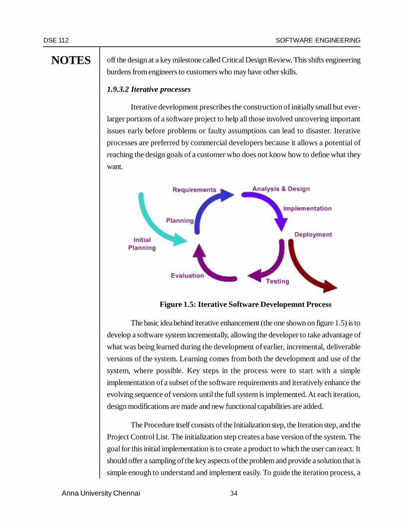
1.9.3.2 Iterative processes
Iterative development prescribes the construction of initially small but ever-larger portions of a software project to help all those involved uncovering importantissues early before problems or faulty assumptions can lead to disaster. Iterativeprocesses are preferred by commercial developers because it allows a potential ofreaching the design goals of a customer who does not know how to define what theywant.
Figure 1.5: Iterative Software Developemnt Process
The basic idea behind iterative enhancement (the one shown on figure 1.5) is todevelop a software system incrementally, allowing the developer to take advantage ofwhat was being learned during the development of earlier, incremental, deliverableversions of the system. Learning comes from both the development and use of thesystem, where possible. Key steps in the process were to start with a simpleimplementation of a subset of the software requirements and iteratively enhance theevolving sequence of versions until the full system is implemented. At each iteration,design modifications are made and new functional capabilities are added.
The Procedure itself consists of the Initialization step, the Iteration step, and theProject Control List. The initialization step creates a base version of the system. Thegoal for this initial implementation is to create a product to which the user can react. Itshould offer a sampling of the key aspects of the problem and provide a solution that issimple enough to understand and implement easily. To guide the iteration process, a

DSE 112 SOFTWARE ENGINEERING
NOTES
35 Anna University Chennai
project control list is created that contains a record of all tasks that need to be performed.It includes such items as new features to be implemented and areas of redesign of theexisting solution. The control list is constantly being revised as a result of the analysisphase.
The iteration involves the redesign and implementation of a task from projectcontrol list, and the analysis of the current version of the system. The goal for the designand implementation of any iteration is to be simple, straightforward, and modular,supporting redesign at that stage or as a task added to the project control list. The codecan, in some cases, represent the major source of documentation of the system. Theanalysis of an iteration is based upon user feedback, and the program analysis facilitiesavailable. It involves analysis of the structure, modularity, usability, reliability, efficiency,and achievement of goals. The project control list is modified in light of the analysisresults.
1.9.3.3 Spiral Model Process
Figure 1.6: The Spiral Model of Software Development

DSE 112 SOFTWARE ENGINEERING
NOTES
36Anna University Chennai
In order to overcome the cons of “The Waterfall Model”, it was necessary todevelop a new Software Development Model, which could help in ensuring the successof software project. One such model was developed which incorporated the commonmethodologies followed in “The Waterfall Model”, but it also eliminated almost everypossible/known risk factors from it. This model is referred as “The Spiral Model” or“Boehm’s Model”.
There are four phases in the “Spiral Model” (shown in figure 1.6)which are:Planning, Evaluation, Risk Analysis and Engineering. These four phases are iterativelyfollowed one after other in order to eliminate all the problems, which were faced in“The Waterfall Model”. Iterating the phases helps in understating the problems associatedwith a phase and dealing with those problems when the same phase is repeated nexttime, planning and developing strategies to be followed while iterating through the phases.The phases in “Spiral Model” are:
Plan: In this phase, the objectives, alternatives and constraints of the project aredetermined and are documented. The objectives and other specifications are fixed inorder to decide which strategies/approaches to follow during the project life cycle.
Risk Analysis: This phase is the most important part of “Spiral Model”. In this phaseall possible (and available) alternatives, which can help in developing a cost effectiveproject are analyzed and strategies are decided to use them. This phase has beenadded specially in order to identify and resolve all the possible risks in the projectdevelopment. If risks indicate any kind of uncertainty in requirements, prototyping maybe used to proceed with the available data and find out possible solution in order todeal with the potential changes in the requirements.
Engineering: In this phase, the actual development of the project is carried out. Theoutput of this phase is passed through all the phases iteratively in order to obtainimprovements in the same.
Customer Evaluation: In this phase, developed product is passed on to the customerin order to receive customer’s comments and suggestions which can help in identifyingand resolving potential problems/errors in the software developed. This phase is verymuch similar to TESTING phase.
The process progresses in spiral sense to indicate iterative path followed,progressively more complete software is built as we go on iterating through all four

DSE 112 SOFTWARE ENGINEERING
NOTES
37 Anna University Chennai
phases. The first iteration in this model is considered to be most important, as in the firstiteration almost all possible risk factors, constraints, requirements are identified and inthe next iterations all known strategies are used to bring up a complete software system.The radical dimensions indicate evolution of the product towards a complete system.
However, as every system has its own pros and cons, “The Spiral Model”does have its pros and cons too. As this model is developed to overcome thedisadvantages of the “Waterfall Model”, to follow “Spiral Model”, highly skilled peoplein the area of planning, risk analysis and mitigation, development, customer relation etc.are required. This along with the fact that the process needs to be iterated more thanonce demands more time and is somehow expensive task.
1.9.3.4 Agile Software Development Process
Agile software development processes are built on the foundation of iterativedevelopment. To that foundation they add a lighter, more people-centric viewpoint thantraditional approaches. Agile processes use feedback, rather than planning, as theirprimary control mechanism. The feedback is driven by regular tests and releases of theevolving software.
Agile processes seem to be more efficient than older methodologies, using lessprogrammer time to produce more functional, higher quality software, but have thedrawback from a business perspective that they do not provide long-term planningcapability.
Agile software development is a conceptual framework for undertaking softwareengineering projects that embraces and promotes evolutionary change throughout theentire life-cycle of the project.
There are a number of agile software development methods; most attempt tominimize risk by developing software in short timeboxes, called iterations, which typicallylast one to four weeks. Each iteration is like a miniature software project of its own, andincludes all of the tasks necessary to release the mini-increment of new functionality:planning, requirements analysis, design, coding, testing, and documentation. While aniteration may not add enough functionality to warrant releasing the product, an agilesoftware project intends to be capable of releasing new software at the end of everyiteration. In many cases, software is released at the end of each iteration. This isparticularly true when the software is web-based and can be released easily. Regardless,at the end of each iteration, the team re-evaluates project priorities.
DSE 112 SOFTWARE ENGINEERING
NOTES
38Anna University Chennai
Agile methods emphasize real-time communication, preferably face-to-face,over written documents. Most agile teams are located in a bullpen and include all thepeople necessary to finish software. At a minimum, this includes programmers and their“customers” (customers are the people who define the product; they may be productmanagers, business analysts, or actual customers). The bullpen may also include testers,interaction designers, technical writers, and managers.
Agile methods also emphasize working software as the primary measure ofprogress. Combined with the preference for face-to-face communication, agile methodsproduce very little written documentation relative to other methods. This has resulted incriticism of agile methods as being undisciplined.
1.9.3.5 Extreme Programming
Extreme Programming, XP, is the best-known agile process.
In XP, the phases are carried out in extremely small (or “continuous”) stepscompared to the older, “batch” processes. The (intentionally incomplete) first passthrough the steps might take a day or a week, rather than the months or years of eachcomplete step in the Waterfall model.
First, one writes automated tests, to provide concrete goals for development.Next is coding (by a pair of programmers), which is complete when all the tests pass,and the programmers can’t think of any more tests that are needed. Design andarchitecture emerge out of refactoring, and come after coding. Design is done by thesame people who do the coding. (Only the last feature - merging design and code - iscommon to all the other agile processes.) The incomplete but functional system isdeployed or demonstrated for (some subset of) the users (at least one of which is onthe development team). At this point, the practitioners start again on writing tests for thenext most important part of the system.
While Iterative development approaches have their advantages, softwarearchitects are still faced with the challenge of creating a reliable foundation upon whichto develop. Such a foundation often requires a fair amount of upfront analysis andprototyping to build a development model. The development model often relies uponspecific design patterns and entity relationship diagrams (ERD). Without this upfrontfoundation, Iterative development can create long-term challenges that are significant interms of cost and quality.

DSE 112 SOFTWARE ENGINEERING
NOTES
39 Anna University Chennai
Critics of iterative development approaches point out that these processes placewhat may be an unreasonable expectation upon the recipient of the software: that theymust possess the skills and experience of a seasoned software developer. The approachcan also be very expensive if iterations are not small enough to mitigate risk the up-frontdesign is as necessary for software development as it is for architecture. The problemwith this criticism is that the whole point of iterative programming is that you don’t haveto build the whole house before you get feedback from the recipient. Indeed, in a senseconventional programming places more of this burden on the recipient, as therequirements and planning phases take place entirely before the development begins,and testing only occurs after development is officially over.
In fact, a relatively quiet turn around in the agile community has occurred on thenotion of “evolving” the software without the requirements locked down. In the oldworld this was called requirements creep and never made commercial sense. The Agilecommunity has similarly been “burnt” because, in the end, when the customer asks forsomething that breaks the architecture, and won’t pay for the re-work, the projectterminates in an agile manner.
These approaches have been developed along with web-based technologies.As such, they are actually more akin to maintenance life cycles given that most of thearchitecture and capability of the solutions is embodied within the technology selectedas the backbone of the application.
The Agile community, as their alternative to cogitating and documenting a design,claims refactoring. No equivalent claim is made of re-engineering - which is an artifactof the wrong technology being chosen, therefore the wrong architecture. Both arerelatively costly. Claims that 10%-15% must be added to an iteration to account forrefactoring of old code exist. However, there is no detail as to whether this value accountsfor the re-testing or regression testing that must happen where old code is touched. Ofcourse, throwing away the architecture is more costly again. In fact, a survey of the“design less” approach paints a picture of the cost incurred where this class of approachis used (Software Development at Microsoft Observed). Note the heavy emphasishere on constant reverse engineering by programming staff rather than managing a centraldesign.
Test Driven Development (TDD) is a useful output of the Agile camp but raisesa conundrum. TDD requires that a unit test be written for a class before the class is

DSE 112 SOFTWARE ENGINEERING
NOTES
40Anna University Chennai
written. Therefore, the class firstly has to be “discovered” and secondly defined insufficient detail to allow the write-test-once-and-code-until-class-passes model thatTDD actually uses. This is actually counter to agile approaches, particularly (so-called)Agile Modeling, where developers are still encouraged to code early, with light design.Obviously to get the claimed benefits of TDD a full design down to class and, say,responsibilities (captured using, for example, Design By Contract) is necessary. Thiscounts towards iterative development, with a design locked down, but not iterativedesign - as heavy refactoring and re-engineering negate the usefulness of TDD.
Q1.9.4 Questions
1. Write a short note on the Software Development Process.2. What are process models?3. List out the various process models that can be used to develop a system4. Explain the Water fall process model in detail5. Explain the suitability of the spiral model for software development.6. What is Agile Development process model? Explain the Extreme Programming
model in detail.7. Compare the various process models.8. Explain in detail about the Software Development process.
1.10 PROJECT MANAGEMENT PROCESS
1.10.1 Core Project Management Process Overview
The core project management process is divided into five main stages. Each ofthe project stages is described in its own section. The five stages that are identifiedinclude:
1. Starting the Project:
Starting from idea realization through to the development and evaluation of abusiness case and prioritization of the potential project investments against thegovernment/Departmental objectives and other organizational priorities and resourceconstraints.
2. Project Planning:
This stage is critical to successful resourcing and execution of the project activitiesand it includes the development of the overall project structure, the activities and work

DSE 112 SOFTWARE ENGINEERING
NOTES
41 Anna University Chennai
plan/timeline that will form the basis of the project management process throughout theproject lifecycle. Where Treasury Board approval is required, project planning is usuallyconducted in two major iterations at increasing levels of planning detail and estimationaccuracy.
3. Approving the Project:
The Treasury Board Approval criteria should be consulted to determine whetheryour project requires Treasury Board Approval. This stage details the requirements ofthe Treasury Board Approval process. Even if your project does not officially requirethat the Treasury Board Project Approval Process be applied, you can gain by referencingand adopting those components that may provide extra rigor and support to your projectapproach.
4. Project Implementation:
Against the project plan and project organization structure defined in the previousstage, the project activities are executed, tracked and measured. The projectimplementation stage not only includes the completion of planned activities, but also theevaluation of the success and contribution of this effort and the continual review andreflection of project status and outstanding issues against the original project businesscase.
5. Project Close Out and Wrap-up:
One of the key success criteria for continuous process improvement involvesdefining a formal process for ending a project. This includes evaluating the successfulaspects of the project as well as identifying opportunities for improvement, identificationof project “best practices” that can be leveraged in future projects, and evaluating theperformance of project team members.
Q1.10.2 Questions
1. What are the phases of the Project Management Process?2. Explain the various stages involved in the PMP?
1.11 SOFTWARE CONFIGURATION MANAGEMENT PROCESS
SCM is a “set of activities designed to control change by identifying the workproducts that are likely to change, establishing relationships among them, defining

DSE 112 SOFTWARE ENGINEERING
NOTES
42Anna University Chennai
mechanisms for managing different versions of these work products, controlling thechanges imposed, and auditing and reporting on the changes made.” In other words,SCM is a methodology to control and manage a software development project.
SCM concerns itself with answering the question: somebody did something,how can one reproduce it? Often the problem involves not reproducing “it” identically,but with controlled, incremental changes. Answering the question will thus become amatter of comparing different results and of analyzing their differences. Traditional CMtypically focused on controlled creation of relatively simple products. Nowadays,implementers of SCM face the challenge of dealing with relatively minor incrementsunder their own control, in the context of the complex system being developed.
Traditional SCM process is looked upon as the best-fit solution to handlingchanges in software projects. Traditional SCM process identifies the functional andphysical attributes of software at various points in time and performs systematic controlof changes to the identified attributes for the purpose of maintaining software integrityand traceability throughout the software development life cycle.
1.11.1 The goals of SCM are generally:
1. Configuration Identification- What code are we working with?2. Configuration Control- Controlling the release of a product and its changes.3. Status Accounting- Recording and reporting the status of components.4. Review- Ensuring completeness and consistency among components.5. Build Management- Managing the process and tools used for builds.6. Process Management- Ensuring adherence to the organization’s development
process.7. Environment Management- Managing the software and hardware that host our
system.8. Teamwork- Facilitate team interactions related to the process.
Defect Tracking- making sure every defect has traceability back to the source

DSE 112 SOFTWARE ENGINEERING
NOTES
43 Anna University Chennai
Figure 1.7: Version Control – Schematic Diagram
The SCM process further defines the need to trace the changes and the abilityto verify that the final delivered software has all the planned enhancements that aresupposed to be part of the release. The figure 1.7 shown above gives an idea as to howthe different versions of the software that is getting developed are maintained.
1.11.2 SCM Procedures:
The traditional SCM identifies four procedures that must be defined for eachsoftware project to ensure a good SCM process is implemented. They are
1. Configuration Identification2. Configuration Control3. Configuration Status Accounting4. Configuration Authentication
Most of this section will cover traditional SCM theory. Do not consider this asboring subject since this section defines and explains the terms that will be used throughoutthis document.
1. Configuration Identification
Software is usually made up of several programs. Each program, its relateddocumentation and data can be called as a “configurable item”(CI). The number of CIin any software project and the grouping of artifacts that make up a CI is a decisionmade of the project. The end product is made up of a bunch of CIs.
The status of the CIs at a given point in time is called as a baseline. The baselineserves as a reference point in the software development life cycle. Each new baseline isthe sum total of an older baseline plus a series of approved changes made on the CI.

DSE 112 SOFTWARE ENGINEERING
NOTES
44Anna University Chennai
A baseline is considered to have the following attributes
1. Functionally complete
A baseline will have a defined functionality. The features and functions of thisparticular baseline will be documented and available for reference. Thus the capabilitiesof the software at a particular baseline are well known.
2. Known Quality
The quality of a baseline will be well defined. i.e. all known bugs will bedocumented and the software will have undergone a complete round of testing beforebeing put define as the baseline.
3. Immutable and completely re-creatable
A baseline, once defined, cannot be changed. The list of the CIs and theirversions are set in stone. Also, all the CIs will be under version control so the baselinecan be recreated at any point in time.
4. Configuration Control
The process of deciding, co-coordinating the approved changes for the proposedCIs and implementing the changes on the appropriate baseline is called Configurationcontrol.
It should be kept in mind that configuration control only addresses the processafter changes are approved. The act of evaluating and approving changes to softwarecomes under the purview of an entirely different process called change control.
5. Configuration Status Accounting
Configuration status accounting is the bookkeeping process of each release.This procedure involves tracking what is in each version of software and the changesthat lead to this version.
Configuration status accounting keeps a record of all the changes made to theprevious baseline to reach the new baseline.
6. Configuration Authentication
Configuration authentication (CA) is the process of assuring that the new baselinehas all the planned and approved changes incorporated. The process involves verifyingthat all the functional aspects of the software is complete and also the completeness ofthe delivery in terms of the right programs, documentation and data are being delivered.

DSE 112 SOFTWARE ENGINEERING
NOTES
45 Anna University Chennai
The configuration authentication is an audit performed on the delivery before itis opened to the entire world.
1.11.3 Tools that aid Software Configuration Management
1. Concurrent Versions System (CVS)2. Revision Control System (RCS)3. Source Code Control System (SCCS)
Commercial Tools
1. Rational Clear Case2. Polytron Version Control System (PVCS)3. Microsoft Visual SourceSafe
1.12 CAPABILITY MATURITY MODEL (CMM)
The Capability Maturity Model defined by the Software Engineering Institute(SEI) for Software describes the principles and practices to achieve a certain level ofsoftware process maturity. The model is intended to help software organizations improvethe maturity of their software processes in terms of an evolutionary path from ad hoc,chaotic processes to mature, disciplined software processes. The CMM is designedtowards organizations in improving their software processes for building better softwarefaster and at a lower cost. The Software Engineering Institute (SEI) defines five levelsof maturity of a software development process. (Please refer to the figure 1.2 shownbelow)
1.12.1 Structure of CMM
The CMM involves the following aspects:
Maturity Levels: It is a layered framework providing a progression to the disciplineneeded to engage in continuous improvement (It is important to state here that anorganization develops the ability to assess the impact of a new practice, technology, ortool on their activity. Hence it is not a matter of adopting these, rather it is a matter ofdetermining how innovative efforts influence existing practices. This really empowersprojects, teams, and organizations by giving them the foundation to support reasonedchoice.)
Key Process Areas: A Key Process Area (KPA) identifies a cluster of related activitiesthat, when performed collectively, achieve a set of goals considered important.

DSE 112 SOFTWARE ENGINEERING
NOTES
46Anna University Chennai
Goals: The goals of a key process area summarize the states that must exist for thatkey process area to have been implemented in an effective and lasting way. The extentto which the goals have been accomplished is an indicator of how much capability theorganization has established at that maturity level. The goals signify the scope, boundaries,and intent of each key process area.
Common Features: Common features include practices that implement andinstitutionalize a key process area. These five types of common features include:Commitment to Perform, Ability to Perform, Activities Performed, Measurement andAnalysis, and Verifying Implementation.
Key Practices: The key practices describe the elements of infrastructure and practicethat contribute most effectively to the implementation and institutionalization of the keyprocess areas.
1.12.2 Levels of the CMM
Figure 1.8: Levels of Capability Maturity Model

DSE 112 SOFTWARE ENGINEERING
NOTES
47 Anna University Chennai
There are five levels of the CMM as shown in the figure 1.8 are;
Level 1 - Initial
At maturity level 1, processes are usually ad hoc, and the organization usuallydoes not provide a stable environment. Success in these organizations depends on thecompetence and heroics of the people in the organization, and not on the use of provenprocesses. In spite of this ad hoc, chaotic environment, maturity level 1 organizationsoften produce products and services that work; however, they frequently exceed thebudget and schedule of their projects.
Maturity level 1 organizations are characterized by a tendency to over commit,abandon processes in the time of crisis, and not be able to repeat their past successesagain.
Level 1 software project success depends on having high quality people.
Level 2 - Repeatable
At maturity level 2, software development successes are repeatable. Theprocesses may not repeat for all the projects in the organization. The organization mayuse some basic project management to track cost and schedule.
Process discipline helps ensure that existing practices are retained during timesof stress. When these practices are in place, projects are performed and managedaccording to their documented plans.
Project status and the delivery of services are visible to management at definedpoints (for example, at major milestones and at the completion of major tasks).
Basic project management processes are established to track cost, schedule,and functionality. The minimum process discipline is in place to repeat earlier successeson projects with similar applications and scope. There is still a significant risk of exceedingcost and time estimates.
Level 3 - Defined
The organization’s set of standard processes, which are the basis for level 3,are established and improved over time. These standard processes are used to establishconsistency across the organization. Projects establish their defined processes by theorganization’s set of standard processes according to tailoring guidelines.

DSE 112 SOFTWARE ENGINEERING
NOTES
48Anna University Chennai
The organization’s management establishes process objectives based on theorganization’s set of standard processes and ensures that these objectives areappropriately addressed.
A critical distinction between level 2 and level 3 is the scope of standards,process descriptions, and procedures. At level 2, the standards, process descriptions,and procedures may be quite different in each specific instance of the process (forexample, on a particular project). At level 3, the standards, process descriptions, andprocedures for a project are tailored from the organization’s set of standard processesto suit a particular project or organizational unit.
Effective project management system is implemented with the help of goodproject management software.
Level 4 - Quantitatively Managed
Using precise measurements, management can effectively control the softwaredevelopment effort. In particular, management can identify ways to adjust and adaptthe process to particular projects without measurable losses of quality or deviationsfrom specifications. Organizations at this level set quantitative quality goals for bothsoftware process and software maintenance. Sub processes are selected that significantlycontribute to overall process performance. These selected sub processes are controlledusing statistical and other quantitative techniques. A critical distinction between maturitylevel 3 and maturity level 4 is the predictability of process performance. At maturitylevel 4, the performance of processes is controlled using statistical and other quantitativetechniques, and is quantitatively predictable. At maturity level 3, processes are onlyqualitatively predictable.
Level 5 - Optimizing
Maturity level 5 focuses on continually improving process performance throughboth incremental and innovative technological improvements. Quantitative process-improvement objectives for the organization are established, continually revised to reflectchanging business objectives, and used as criteria in managing process improvement.The effects of deployed process improvements are measured and evaluated against thequantitative process-improvement objectives. Both the defined processes and theorganization’s set of standard processes are targets of measurable improvement activities.

DSE 112 SOFTWARE ENGINEERING
NOTES
49 Anna University Chennai
Process improvements to address common causes of process variation andmeasurably improve the organization’s processes are identified, evaluated, and deployed.
Optimizing processes that are nimble, adaptable and innovative depends onthe participation of an empowered workforce aligned with the business values andobjectives of the organization. The organization’s ability to rapidly respond to changesand opportunities is enhanced by finding ways to accelerate and share learning.
A critical distinction between maturity level 4 and maturity level 5 is the type ofprocess variation addressed. At maturity level 4, processes are concerned with addressingspecial causes of process variation and providing statistical predictability of the results.Though processes may produce predictable results, the results may be insufficient toachieve the established objectives. At maturity level 5, processes are concerned withaddressing common causes of process variation and changing the process (that is,shifting the mean of the process performance) to improve process performance (whilemaintaining statistical probability) to achieve the established quantitative process-improvement objectives.
Associated with each level from level two onwards are key areas, which anorganization is required to focus on to move on to the next level. Such focus areas arecalled as Key Process Areas (KPA) in CMM parlance. As part of level 2 maturity, oneof the KPAs that have been identified is SCM. Thus any project that has a good SCMprocess can be leveraged as satisfying one of the KPAs of CMM.
Having known the various software development life cycle models, let us nowstudy about the first stage of the SDLC, which is the Requirements Engineering. Let usstudy how the requirements are elicited from the problem definition. What are thechallenges in eliciting the requirements, what is an SRS? All these are given in detail in
the next unit.

DSE 112 SOFTWARE ENGINEERING
NOTES
50Anna University Chennai
Q1.12.3 Questions
1. What do you mean by Configuration Management in the SE perspective?
2. How important is the SCM process in Software Engineering?
3. Define the various steps in SCM process?
4. Explain in detail the Software Configuration Management Process.
5. What is CMM?
6. Explain the importance of CMM with respect to software engineering.
7. Briefly outline the structure of the CMM.
8. Explain the various levels of CMM
REFERENCES
1.Software Engineering A Practitioner’s Approach, By Roger. S.Pressman, Mc
Graw Hill International 6th edition, 2005.
http://www.ics.uci.edu/~wscacchi / Papers / SE-Encyc / Process-Models-SE-Encyc.pdf

DSE 112 SOFTWARE ENGINEERING
NOTES
51 Anna University Chennai
UNIT II2.1 INTODUCTION
In software engineering, requirements analysis encompasses those tasks thatgo into determining the requirements of a new or altered system, taking account of thepossibly conflicting requirements of the various stakeholders, such as users. Requirementsanalysis is critical to the success of a project.
Systematic requirements analysis is also known as requirements engineering. Itis sometimes referred to loosely by names such as requirements gathering, requirementscapture, or requirements specification. The term “requirements analysis” can also beapplied specifically to the analysis proper (as opposed to elicitation or documentationof the requirements, for instance).
Requirements must be measurable, testable, related to identified business needsor opportunities, and defined to a level of detail sufficient for system design.
2.2 LEARNING OBJECTIVES
1. The software requirement analysis techniques.2. The Software Requirement Specification (SRS)3. Characteristics of a good SRS document?4. The problems faced during the requirements analysis phase.5. Software Requiremnt Validation6. Sotware Requirement Metrics
What is Requirement?
The IEEE definitions of “requirement” are given below.1. A condition or capability needed by a user to solve a problem or achieve an
objective

DSE 112 SOFTWARE ENGINEERING
NOTES
52Anna University Chennai
2. A condition or capability that must be met or possessed by a system or systemcomponent to satisfy a contract, standard, specification or other formally imposeddocument
3. A documented representation of a condition or capability as in (1) or (2)
2.3 REQUIREMENTS ENGINEERING PROCESS
The block diagram (figure 2.0) shown below gives an overall idea about therequirement engineering process. It starts with the feasibility study and ends with thepreparation of the requirements document.
Figure 2.0: Requirement Engineering Process
Main techniques
Conceptually, requirements analysis includes three types of activity:
1. Feasibility Study: A feasibility study decides whether or not the proposed systemis worthwhile.
2. Eliciting and Analyzing requirements: the task of communicating withcustomers and users to determine what their requirements are and analysis is thetask of determining whether the stated requirements are unclear, incomplete,ambiguous, or contradictory and resolving these issues.
F easibility
stud y
R equir ements elicitation and anal ysis
R equir ements specification
R equir ements validation
F easibility r epor t
S ystem models
User and system requirements
R equir ements document

DSE 112 SOFTWARE ENGINEERING
NOTES
53 Anna University Chennai
3. Requirements Specification: Requirements may be documented in variousforms, such as natural-language documents, use cases, user stories, or processspecifications.
4. Requirements Validation: Concerned with demonstrating that the requirementsdefine the system that the customer really wants. The requirements error costsare high so validation is very important
The outputs of the requirement engineering process are the agreed requirements,system specification and system models as shown in the figure 2.1 below.
Figure 2.1: Inputs and Outputs of the Requirement Engineering Process
2.4 SOFTWARE REQUIREMENTS PROBLEMS
The problems covered in five common errors in requirements analysis.
1. Customers Don’t Know What They Want
This is often true because much of development has to do with technologythat’s beyond the customer’s knowledge. In software development especially largeand complex software with many interfaces requirements don’t always affect customers.Requirements often focus on the back-end, processing and system interfaces.
2. Different stakeholders may have conflicting requirements.
The software project has stakeholders with varied knowledge and who havedifferent levels of stake in the project. There is always a good chance that they havedifferent views, which often conflict with each other. We need to consider all the possiblerequirements and need to do a study in order to solve the conflicts. Trade offs need tobe done most of the times.
Agreedrequirements
Systemspecification
Systemmodels
Requirementsengineering process
Stakeholderneeds
Organisationalstandards
Domaininformation
Regulations
Existingsystems
information

DSE 112 SOFTWARE ENGINEERING
NOTES
54Anna University Chennai
3. Stakeholders express requirements in their own terms.
We need to remember that the stakeholders of the project are not technicalpeople. They just have a vague idea as to what they want. They will explain their idea intheir own terms and may often give us a problem statement that conveys very littleabout their needs.
4. Requirements Change during the Project
New stakeholders may emerge and the business environment change. Anyoneinvolved in development should have a change request process in place, even a one-person business. Accept that there will be changes and prepare a change request whenthis happens. Show the customer how it affects the milestones and get sign off. Anotherway is to have a phase 1 or soft launch and then add the new requirements for phase 2.
5. Timeline Trouble
The customer accepts responsibility for the delay. Be realistic. Map out thetimeline based on an analysis of the requirements. If it’s tight leaving no room for erroror impossible communicate this. Which would you rather have? No client because yousaid the timeline wasn’t doable or having a client and missing deadlines that could hurta company’s reputation?
6. Communication Gaps
All the stakeholders of the project may not be available at all times and anydiscussion made on the project should be made known to all the stakeholders. Most ofthe times, there is a good chance that there will be communication gap and hence thingsare likely to get lost in between.
7. Organisational and political factors may influence the system requirements
This is a difficult problem to overcome with diversity of variables that can get inthe way. One way is to communicate in terms of what’s in it for the other person ratherthan your firm or someone else in your client’s company.
Q 2.4 Questions
a) What are the problems faced in the Software Requirements?b) How can the issues in the requirements phase be effectively managed so
that we prepare a good SRS?c) “Requirements keep changing” Write a note on this.

DSE 112 SOFTWARE ENGINEERING
NOTES
55 Anna University Chennai
2.5 THE REQUIREMENTS SPIRAL
As in the case of the spiral model of the software development, the requirementsspiral is one of the models followed for eliciting requirements and preparing the SRSdocument. The figure 2.2, shown below shown below shows the requirements spiral.
Figure 2.2: The Requirements Spiral
Requirements analysis can be a long and arduous process during which manydelicate psychological skills are involved. New systems change the environment andrelationships between people, so it is important to identify all the stakeholders, take intoaccount all their needs and ensure they understand the implications of the new systems.Analysts can employ several techniques to elicit the requirements from the customer.Historically, this has included such things as holding interviews, or holding focus groups(more aptly named in this context as requirements workshops - see below) and creatingrequirements lists. More modern techniques include prototyping, and use cases. Wherenecessary, the analyst will employ a combination of these methods to establish theexact requirements of the stakeholders, so that a system that meets the business needsis produced.
Requirementsclassif ication and
organisation
Requirementsprior itization and
negotiation
Requirementsdocumentation
Requirementsdiscove ry

DSE 112 SOFTWARE ENGINEERING
NOTES
56Anna University Chennai
Figure 2.3: Schematic Diagram of the Requirements Elicitation and Analysis
2.6 TECHNIQUES FOR ELICITING REQUIREMENTS
There are many ways by which the requirements can be elicited for the givenproblem statement. Eliciting requirements is a very tough task as the problem statementgiven by the customer is often very ambiguous and unclear. It is the duty of therequirements engineer to elicit the requirements from the given problem statement. Manytechniques for the elicitation of the requirements have been proposed and the importantones are discusses here.
2.6.1 Stakeholder interviews
Stakeholder interviews are a common method used in requirement analysis.Some selection is usually necessary, cost being one factor in deciding whom to interview.These interviews may reveal requirements not previously envisaged as being within thescope of the project, and requirements may be contradictory. However, stakeholdershall have an idea of his expectation or shall have visualized his requirements.
2.6.2 Requirement workshops
In some cases it may be useful to gather stakeholders together in “requirementworkshops”. These workshops are more properly termed Joint Requirements
Analysis
problem statement
functional model
nonfunctional requirements
analysis object m
Requirements elicitation
dynamic model
Analysis Model
Requirements Specification

DSE 112 SOFTWARE ENGINEERING
NOTES
57 Anna University Chennai
Development (JRD) sessions, where requirements are jointly identified and defined bystakeholders.
It may be useful to carry out such workshops in a controlled environment, sothat the stakeholders are not distracted. A facilitator can be used to keep the processfocused and these sessions will often benefit from a dedicated scribe to document thediscussion. Facilitators may make use of a projector and diagramming software or mayuse props as simple as paper and markers. One role of the facilitator may be to ensurethat the weight attached to proposed requirements is not overly dependent on thepersonalities of those involved in the process.
2.6.3 Ethnography
Social scientists spend a considerable time observing and analysing how peopleactually work. People do not have to explain or articulate their work. Social andorganisational factors of importance may be observed. Ethnographic studies have shownthat work is usually richer and more complex than suggested by simple system models.
2.6.3.1 Scope of Ethnography
The scope of ethnography which is shown in the figure 2.4 below, gives howthe requirements are elicited and the SRS is prepared by the ethnography technique.
Requirements that are derived from the way that people actually work ratherthan the way I which process definitions suggest that they ought to work.
Requirements that are derived from cooperation and awareness of other people’sactivities
Figure 2.4: Scope of Ethnography
2.6.4 Prototypes
In the mid-1980s, prototyping became seen as the solution to the requirementsanalysis problem. Prototypes are mock ups of the screens of an application which
Ethno g raphicanal ysis
Debriefingmeetings
Focusedethno g raph y
Prototypeevalua tion
Generic systemde vel opment
Systemproto yping

DSE 112 SOFTWARE ENGINEERING
NOTES
58Anna University Chennai
allow users to visualize the application that isn’t yet constructed. Prototypes help usersget an idea of what the system will look like, and make it easier for users to makedesign decisions without waiting for the system to be built. Major improvements incommunication between users and developers were often seen with the introduction ofprototypes. Early views of the screens led to fewer changes later and hence reducedoverall costs considerably.
However, over the next decade, while proving a useful technique, it did notsolve the requirements problem:
1. Managers once they see the prototype have a hard time understanding that thefinished design will not be produced for some time.
2. Designers often feel compelled to use the patched together prototype code in thereal system, because they are afraid to ‘waste time’ starting again.
3. Prototypes principally help with design decisions and user interface design.However, they can’t tell you what the requirements were originally.
4. Designers and end users can focus too much on user interface design and toolittle on producing a system that serves the business process.
Prototypes can be flat diagrams or working applications using synthesizedfunctionality. Wireframes are made in a variety of graphic design documents, and oftenremove all color from the software design in instances where the final software is expectedto have graphic design applied to it. This helps to prevent confusion over the final visuallook and feel of the application.
2.6.5 Use cases
A use case is a technique for documenting the potential requirements of a newsystem or software change. Each use case provides one or more scenarios that conveyhow the system should interact with the end user or another system to achieve a specificbusiness goal. Use cases typically avoid technical jargon, preferring instead the languageof the end user or domain expert. Use cases are often co-authored by softwaredevelopers and end users.
Use cases are deceptively simple tools for describing the behavior of the software.A use case contains a textual description of all of the ways which the intended userscould work with the software through its interface. Use cases do not describe anyinternal workings of the software, nor do they explain how that software will beimplemented. They simply show the steps that the user follows to use the software todo his work. All of the ways that the users interact with the software can be describedin this manner.

DSE 112 SOFTWARE ENGINEERING
NOTES
59 Anna University Chennai
During the 1990s, use cases have rapidly become the most common practicefor capturing functional requirements. This is especially the case within the object-orientedcommunity where they originated, but their applicability is not restricted to object-oriented systems, because use cases are not object-oriented in nature.
Each use case focuses on describing how to achieve a single business goal ortask. From a traditional software engineering perspective, a use case describes just onefeature of the system. For most software projects, this means that perhaps tens orsometimes hundreds of use cases are needed to fully specify the new system. Thedegree of formality of a particular software project and the stage of the project willinfluence the level of detail required in each use case.
Article Printing Use case: an Illustrative Example
The example discussed, as shown in the figure 2.5 below, is regarding theprinting of an article. The actors for this particular system are the library user, the bookssupplier and the library staff. The article search, article printing, user administration andcatalogue services.
Figure 2.5: Use Case Diagram for the Article Printing Example
Article printing
Article search
User administration
Suppl ier Catalogue services
LibraryUser
LibraryStaff

DSE 112 SOFTWARE ENGINEERING
NOTES
60Anna University Chennai
A use case defines the interactions between external actors and the systemunder consideration to accomplish a business goal. Actors are parties outside the systemthat interact with the system; an actor can be a class of users, a role users can play, oranother system.
Use cases treat the system as a “black box”, and the interactions with thesystem, including system responses, are as perceived from outside the system. This isdeliberate policy, because it simplifies the description of requirements and avoids thetrap of making assumptions about how this functionality will be accomplished.
A use case should:
1. describe a business task to serve a business goal
2. be at an appropriate level of detail
3. be short enough to implement by one software developer in a single release
Use cases can be very good for establishing functional requirements, but theyare not suited to capturing Non-Functional Requirements. However PerformanceEngineering specifies that each critical use case should have an associated performanceoriented non-functional requirement.
2.7 SOFTWARE REQUIREMENTS SPECIFICATION (SRS)
A software requirements specification (SRS) is a complete description of thebehavior of the system to be developed. It includes a set of use cases that describe allof the interactions that the users will have with the software. Use cases are also knownas functional requirements. In addition to use cases, the SRS also contains nonfunctional(or supplementary) requirements. Non-functional requirements are requirements whichimpose constraints on the design or implementation (such as performance requirements,quality standards, or design constraints).
Recommended approaches for the specification of software requirements aredescribed by IEEE 830-1998. This standard describes possible structures, desirablecontents, and qualities of a software requirements specification.
Stakeholder identification
A major new emphasis in the 1990s was a focus on the identification ofstakeholders. It is increasingly recognized that stakeholders are not limited to theorganization employing the analyst. Other stakeholders will include:

DSE 112 SOFTWARE ENGINEERING
NOTES
61 Anna University Chennai
1. those organizations that integrate (or should integrate) horizontally with theorganization the analyst is designing the system for
2. any back office systems or organizations3. Senior management
Stakeholder issues
There are many ways the users can inhibit requirements gathering:
1. Users don’t understand what they want2. Users won’t commit to a set of written requirements3. Users insist on new requirements after the cost and schedule have been fixed.4. Communication with users is slow5. Users often do not participate in reviews or are incapable of doing so.6. Users are technically unsophisticated7. Users don’t understand the development process.
This may lead to the situation where user requirements keep changing evenwhen system or product development has been started.
Engineer/developer issues
Possible problems caused by engineers and developers during requirementsanalysis are:
1. Technical personnel and end users may have different vocabularies.Consequently, they can believe they are in perfect agreement until the finishedproduct is supplied.
2. Engineers and developers may try to make the requirements fit an existingsystem or model, rather than develop a system specific to the needs of theclient.
3. Analysis may be often carried out by engineers or programmers, rather thanpersonnel with the people skills and the domain knowledge to understand aclient’s needs properly.
Attempted solutions
One attempted solution to communications problems has been to employspecialists in business or system analysis.
Techniques introduced in the 1990s like Prototyping, Unified Modeling Language(UML), Use cases, and Agile software development were also intended as solutions toproblems encountered with previous methods:

DSE 112 SOFTWARE ENGINEERING
NOTES
62Anna University Chennai
Also, a new class of application simulation or application definition tools hasentered the market. These tools are designed to bridge the communication gap betweenbusiness users and the IT organization and also to allow applications to be ‘test marketed’before any code is produced. The best of these tools offer:
1. electronic whiteboards to sketch application flows and test alternatives2. ability to capture business logic and data needs3. ability to generate high fidelity prototypes that closely imitate the final application4. interactivity5. capability to add contextual requirements and other comments6. ability for remote and distributed users to run and interact with the simulation
Q 2.7 Questions
1. What is Requirement Analysis?2. What is the need for the requirements to be analyzed? State the importance
the same.3. What are the activities in the Requirements Analysis Process?4. What is an use case?5. Explain the requiremets analysis phase in details with an example. Also,
mention the how serious it would be if the requiremnts are not analyzedproperly.
2.8 SOFTWARE REQUIREMENTS SPECIFICATION
2.8.1 What is a Software Requirements Specification?
An SRS is basically an organization’s understanding (in writing) of a customeror potential client’s system requirements and dependencies at a particular point in time(usually) prior to any actual design or development work. It’s a two-way insurancepolicy that assures that both the client and the organization understand the other’srequirements from that perspective at a given point in time.
The SRS document itself states in precise and explicit language those functionsand capabilities a software system must provide, as well as states any required constraintsby which the system must abide. The SRS also functions as a blueprint for completinga project with as little cost growth as possible. The SRS is often referred to as the“parent” document because all subsequent project management documents, such asdesign specifications, statements of work, software architecture specifications, testingand validation plans, and documentation plans, are related to it.

DSE 112 SOFTWARE ENGINEERING
NOTES
63 Anna University Chennai
It’s important to note that an SRS contains functional and nonfunctionalrequirements only; it doesn’t offer design suggestions, possible solutions to technologyor business issues, or any other information other than what the development teamunderstands the customer’s system requirements to be.
A well-designed, well-written SRS accomplishes four major goals:
1. It provides feedback to the customer. An SRS is the customer’s assurancethat the development organization understands the issues or problems to besolved and the software behavior necessary to address those problems.Therefore, the SRS should be written in natural language (versus a formallanguage, explained later in this article), in an unambiguous manner that mayalso include charts, tables, data flow diagrams, decision tables, and so on.
2. It decomposes the problem into component parts. The simple act of writingdown software requirements in a well-designed format organizes information,places borders around the problem, solidifies ideas, and helps break down theproblem into its component parts in an orderly fashion.
3. It serves as an input to the design specification. As mentioned previously, theSRS serves as the parent document to subsequent documents, such as thesoftware design specification and statement of work. Therefore, the SRS mustcontain sufficient detail in the functional system requirements so that a designsolution can be devised.
4. It serves as a product validation check. The SRS also serves as the parentdocument for testing and validation strategies that will be applied to therequirements for verification.
SRSs are typically developed during the first stages of “RequirementsDevelopment,” which is the initial product development phase in which information isgathered about what requirements are needed—and not. This information-gatheringstage can include onsite visits, questionnaires, surveys, interviews, and perhaps a returnon-investment (ROI) analysis or needs analysis of the customer or client’s current businessenvironment. The actual specification, then, is written after the requirements have beengathered and analyzed.
2.8.2 Why Technical Writers should be involved with Software RequirementsSpecifications?
Unfortunately, much of the time, systems architects and programmers writeSRSs with little (if any) help from the technical communications organization. And when

DSE 112 SOFTWARE ENGINEERING
NOTES
64Anna University Chennai
that assistance is provided, it’s often limited to an edit of the final draft just prior to goingout the door. Having technical writers involved throughout the entire SRS developmentprocess can offer several benefits:
1. Technical writers are skilled information gatherers, ideal for eliciting andarticulating customer requirements. The presence of a technical writer on therequirements-gathering team helps balance the type and amount of informationextracted from customers, which can help improve the SRS.
2. Technical writers can better assess and plan documentation projects and bettermeet customer document needs. Working on SRSs provides technical writerswith an opportunity for learning about customer needs firsthand—early in theproduct development process.
3. Technical writers know how to determine the questions that are of concern tothe user or customer regarding ease of use and usability. Technical writers canthen take that knowledge and apply it not only to the specification anddocumentation development, but also to user interface development, to helpensure the UI (User Interface) models the customer requirements.
4. Technical writers involved early and often in the process, can become aninformation resource throughout the process, rather than an information gathererat the end of the process.
In short, a requirements-gathering team consisting solely of programmers,product marketers, systems analysts/architects, and a project manager runs the risk ofcreating a specification that may be too heavily loaded with technology-focused ormarketing focused issues. The presence of a technical writer on the team helps place atthe core of the project those user or customer requirements that provide more of anoverall balance to the design of the SRS, product, and documentation.
2.8.3 What Kind of Information Should an SRS Include?
You probably will be a member of the SRS team (if not, ask to be), whichmeans SRS development will be a collaborative effort for a particular project. In thesecases, your company will have developed SRSs before, so you should have examples(and, likely, the company’s SRS template) to use. But, let’s assume you’ll be startingfrom scratch. Several standards organizations (including the IEEE) have identified ninetopics that must be addressed when designing and writing an SRS:

DSE 112 SOFTWARE ENGINEERING
NOTES
65 Anna University Chennai
1. Interfaces2. Functional Capabilities3. Performance Levels4. Data Structures/Elements5. Safety6. Reliability7. Security/Privacy8. Quality9. Constraints and Limitations
An SRS document typically includes four ingredients, as discussed in the followingsections:
1. A template2. A method for identifying requirements and linking sources3. Business operation rules4. A traceability matrix
2.8.4 SRS Template
The first and biggest step to writing an SRS is to select an existing template thatyou can fine tune for your organizational needs. There’s not a “standard specificationtemplate” for all projects in all industries because the individual requirements that populatean SRS are unique not only from company to company, but also from project to projectwithin any one company. The key is to select an existing template or specification tobegin with, and then adapt it to meet your needs. It would be almost impossible to finda specification or specification template that meets your particular project requirementsexactly. But using other templates as guides is how it’s recommended in the literature onspecification development. Look at what someone else has done, and modify it to fityour project requirements.
Table 2.1 shows what a basic SRS outline might look like. This example is anadaptation and extension of the IEEE Standard 830-1998:
2.8.5 Table 2.1: A sample of a basic SRS outline
1. Introduction1.1 Purpose1.2 Document conventions1.3 Intended audience

DSE 112 SOFTWARE ENGINEERING
NOTES
66Anna University Chennai
1.4 Additional information1.5 Contact information/SRS team members1.6 References
2. Overall Description2.1 Product perspective2.2 Product functions2.3 User classes and characteristics2.4 Operating environment2.5 User environment2.6 Design/implementation constraints2.7 Assumptions and dependencies
3. External Interface Requirements3.1 User interfaces3.2 Hardware interfaces3.3 Software interfaces3.4 Communication protocols and interfaces
4. System Features4.1 System feature A 4.1.1 Description and priority 4.1.2 Action/result 4.1.3 Functional requirements4.2 System feature B
5. Other Nonfunctional Requirements5.1 Performance requirements5.2 Safety requirements5.3 Security requirements5.4 Software quality attributes5.5 Project documentation5.6 User documentation
6. Other RequirementsAppendix A: Terminology/Glossary/Definitions list

DSE 112 SOFTWARE ENGINEERING
NOTES
67 Anna University Chennai
Table 2.2: A sample of a more detailed SRS outline
1. Scope 1.1 Identification.
Identify the system and the software to whichthis document applies, including, asapplicable, identification number(s), title(s),abbreviation(s), version number(s), andrelease number(s).
1.2 System overview.
State the purpose of the system or subsystemto which this document applies.
1.3 Document overview.
Summarize the purpose and contents of thisdocument.
This document comprises six sections:
a. Scopeb. Referenced documentsc. Requirementsd. Qualification provisionse. Requirements traceabilityf. Notes
Describe any security or privacy considerationsassociated with its use.
2. Referenced Documents 2.1 Project documents.
Identify the project management systemdocuments here.
2.2 Other documents.
2.3 Precedence.
2.4 Source of documents.
3. Requirements This section shall be divided into paragraphs tospecify the Computer Software ConfigurationItem (CSCI) requirements, that is, those

DSE 112 SOFTWARE ENGINEERING
NOTES
68Anna University Chennai
characteristics of the CSCI that are conditionsfor its acceptance.CSCI requirements aresoftware requirements generated to satisfy thesystem requirements allocated to this CSCI.Each requirement shall be assigned a project-unique identifier to support testing andtraceability and shall be stated in such a waythat an objective test can be defined for it.
3.1 Required states and modes.
3.2 CSCI capability requirements.
3.3 CSCI external interface requirements.
3.4 CSCI internal interface requirements.
3.5 CSCI internal data requirements.
3.6 Adaptation requirements.
3.7 Safety requirements.
3.8 Security and privacy requirements.
3.9 CSCI environment requirements.
3.10 Computer resource requirements.
3.11 Software quality factors.
3.12 Design and implementation constraints.
3.13 Personnel requirements.
3.14 Training-related requirements.
3.15 Logistics-related requirements.
3.16 Other requirements.
3.17 Packaging requirements.
3.18 Precedence and criticality requirements.
4. Qualification Provisions To be determined.
5. Requirements Traceability To be determined.

DSE 112 SOFTWARE ENGINEERING
NOTES
69 Anna University Chennai
6. Notes This section contains information of a generalor explanatory nature that may be helpful, butis not mandatory.
6.1 Intended use.
This Software Requirements specification shall6.2 Definitions used in this document.
Insert here an alphabetic list of definitionsand their source if different from the declaredsources specified in the “Documentationstandard.”
6.3 Abbreviations used in this document.
Insert here an alphabetic list of theabbreviations and acronyms if not identifiedin the declared sources specified in the“Documentation Standard.”
6.4 Changes from previous issue.
Will be “not applicable” for the initial issue.
Revisions shall identify the method used toidentify changes from the previous issue.
2.8.6 Identify and Link Requirements with Sources
As noted earlier, the SRS serves to define the functional and nonfunctionalrequirements of the product. Functional requirements each have an origin from whichthey came, be it a use case (which is used in system analysis to identify, clarify, andorganize system requirements, and consists of a set of possible sequences of interactionsbetween systems and users in a particular environment and related to a particular goal),government regulation, industry standard, or a business requirement. In developing anSRS, you need to identify these origins and link them to their corresponding requirements.Such a practice not only justifies the requirement, but it also helps assure projectstakeholders that frivolous or spurious requirements are kept out of the specification.
To link requirements with their sources, each requirement included in the SRS

DSE 112 SOFTWARE ENGINEERING
NOTES
70Anna University Chennai
should be labeled with a unique identifier that can remain valid over time as requirementsare added, deleted, or changed. Such a labeling system helps maintain change-recordintegrity while also serving as an identification system for gathering metrics. You canbegin a separate requirements identification list that ties a requirement identification(ID) number with a description of the requirement. Eventually, that requirement ID anddescription become part of the SRS itself and then part of the Requirements TraceabilityMatrix, discussed in subsequent paragraphs.
2.8.7 Identifying Requirements and linking them to their sources
The Table 2.3 shown below is a sample one that illustrates how the requirementsare identified and linked to their sources. Here the Business rule sources are used.
Table 2.3: This table identifies requirements and links them to their sources
No. Paragraph Requirement Business RuleNo. Source
1 5.1.4.1 Understand/communicate usingSMTP protocol IEEE STD xx-xxxx
2 5.1.4.1 Understand/communicate usingPOP protocol IEEE STD xx-xxxx
3 5.1.4.1 Understand/communicate usingIMAP protocol IEEE STD xx-xxxx
4 5.1.4.2 Open at same rate as OE Use Case Doc 4.5.4
2.8.8 Establish Business Rules for Contingencies and Responsibilities
A top-quality SRS should include plans for planned and unplanned contingencies,as well as an explicit definition of the responsibilities of each party, should a contingencybe implemented. Some business rules are easier to work around than others. Forexample, if a customer wants to change a requirement that is tied to a governmentregulation, it may not be ethical and/or legal to be following the law. A project managermay be responsible for ensuring that a government regulation is followed as it relates toa project requirement; however, if a contingency is required, then the responsibility forthat requirement may shift from the project manager to a regulatory attorney. The SRSshould anticipate such actions to the furthest extent possible.

DSE 112 SOFTWARE ENGINEERING
NOTES
71 Anna University Chennai
2.8.9 Establish a Requirements Traceability Matrix
The business rules for contingencies and responsibilities can be defined explicitlywithin a Requirements Traceability Matrix (RTM), or contained in a separate documentand referenced in the matrix, as the example in Table 3 illustrates. Such a practiceleaves no doubt as to responsibilities and actions under certain conditions as they occurduring the product-development phase.
The RTM functions as a sort of “chain of custody” document for requirementsand can include pointers to links from requirements to sources, as well as pointers tobusiness rules. For example, any given requirement must be traced back to a specifiedneed, be it a use case, business essential, industry-recognized standard, or governmentregulation. As mentioned previously, linking requirements with sources minimizes oreven eliminates the presence of spurious or frivolous requirements that lack anyjustification. The RTM is another record of mutual understanding, but also helps duringthe development phase.
As software design and development proceed, the design elements and theactual code must be tied back to the requirement(s) that define them. The RTM iscompleted as development progresses; it can’t be completed beforehand (see Table2.3).
2.8.10 Writing an SRS
Unlike formal language that allows developers and designers some latitude, thenatural language of SRSs must be exact, without ambiguity, and precise because thedesign specification, statement of work, and other project documents are what drivethe development of the final product. That final product must be tested and validatedagainst the design and original requirements. Specification language that allows forinterpretation of key requirements will not yield a satisfactory final product and willlikely lead to cost overruns, extended schedules, and missed deliverable deadlines.
2.8.11 Quality characteristics of an SRS
Table 2.4 shows the fundamental characteristics of a quality SRS, which wereoriginally presented at the April 1998 Software Technology Conference presentation“Doing Requirements Right the First Time.” These quality characteristics are closelytied to what are referred to as “indicators of strength and weakness,” which will bedefined next.

DSE 112 SOFTWARE ENGINEERING
NOTES
72Anna University Chennai
How do we know when we’ve written a “quality” specification? The mostobvious answer is that a quality specification is one that fully addresses all the customerrequirements for a particular product or system. That’s part of the answer. While manyquality attributes of an SRS are subjective, we do need indicators or measures thatprovide a sense of how strong or weak the language is in an SRS. A “strong” SRS isone in which the requirements are tightly, unambiguously, and precisely defined in sucha way that leaves no other interpretation or meaning to any individual requirement.
There’s so much more we could say about requirements and specifications.This information will help you get started when you are called upon—or step up—tohelp the development team. Writing top-quality requirements specifications begins witha complete definition of customer requirements. Coupled with a natural language thatincorporates strength and weakness quality indicators—not to mention the adoption ofa good SRS template—technical communications professionals well-trained inrequirements gathering, template design, and natural language use are in the best positionto create and add value to such critical project documentation.
Table 2.4: Quality Characteristics of a SRS
SRS Quality
CharacteristicWhat It Means
Complete SRS defines precisely all the go-live situations that will be
encountered and the system’s capability to successfully address
them.
Consistent SRS capability functions and performance levels are compatible,
and the required quality features (security, reliability, etc.) do
not negate those capability functions. For example, the only
electric hedge trimmer that is safe is one that is stored in a box
and not connected to any electrical cords or outlets.
Accurate SRS precisely defines the system’s capability in a real-world
environment, as well as how it interfaces and interacts with it.
This aspect of requirements is a significant problem area for
many SRSs.

DSE 112 SOFTWARE ENGINEERING
NOTES
73 Anna University Chennai
Modifiable The logical, hierarchical structure of the SRS should facilitate
any necessary modifications (grouping related issues togetherand separating them from unrelated issues makes the SRS easier
to modify).
Ranked Individual requirements of an SRS are hierarchically arrangedaccording to stability, security, perceived ease/difficulty of
implementation, or other parameter that helps in the design ofthat and subsequent documents.
Testable An SRS must be stated in such a manner that unambiguous
assessment criteria (pass/fail or some quantitative measure) canbe derived from the SRS itself.
Traceable Each requirement in an SRS must be uniquely identified to a
source (use case, government requirement, industry standard,etc.)
Unambiguous SRS must contain requirements statements that can be
interpreted in one way only. This is another area that createssignificant problems for SRS development because of the use
of natural language.
Valid A valid SRS is one in which all parties and project participantscan understand, analyze, accept, or approve it. This is one of
the main reasons SRSs are written using natural language.
Verifiable A verifiable SRS is consistent from one level of abstraction toanother. Most attributes of a specification are subjective and a
conclusive assessment of quality requires a technical review bydomain experts. Using indicators of strength and weakness
provide some evidence that preferred attributes are or are notpresent.

DSE 112 SOFTWARE ENGINEERING
NOTES
74Anna University Chennai
Q 2.8.12 Questions
1. What is Software Requirements Specification?2. What is the need for an SRS?3. What are the ways in which the requirements can be elicited?4. What makes a good SRS?5. Explain in detail the SRS.
2.9SOFTWARE REQUIREMENTS VALIDATION
It is concerned with demonstrating that the requirements define the system thatthe customer really wants. Requirements error costs are high so validation is veryimportant Fixing a requirements error after delivery may cost up to 100 times the costof fixing an implementation error.
2.9.1 Requirements Validation Techniques:
1. Requirements reviews: Systematic manual analysis of the requirements.
2. Prototyping: Using an executable model of the system to check requirements.
3. Test-case generation: Developing tests for requirements to check testability.
4. Traceability Matrix: It is concerned with the relationships betweenrequirements, their sources and the system design
A traceability matrix is a report from the requirements database or repository.What information the report contains depends on your need. Information requirementsdetermine the associated information that you store with the requirements. Requirementsmanagement tools capture associated information or provide the capability to add it.
1. Source traceability
a) Links from requirements to stakeholders who proposed theserequirements;
1. Requirements traceability
a) Links between dependent requirements;
2. Design traceability
a) Links from the requirements to the design;

DSE 112 SOFTWARE ENGINEERING
NOTES
75 Anna University Chennai
The examples show forward and backward tracing between user and systemrequirements. User requirement identifiers begin with “U” and system requirementswith “S.” Tracing S12 to its source makes it clear this requirement is erroneous: it mustbe eliminated, rewritten, or the traceability corrected.
Table 2.5: Forward Traceability: an illustrative example
Backward Traceability: an illustrative example
2.9.2 Verification and Validation activities should include:
1. Analyzing software requirements to determine if they are consistent with, andwithin the scope have, system requirements.
2. Assuring that the requirements are testable and capable of being satisfied.
3. Creating a preliminary version of the Acceptance Test Plan, including averification matrix, which relates requirements to the tests used to demonstratethat requirements are satisfied.
4. Beginning development, if needed, of test beds and test data generators.5. The phase-ending Software Requirements Review (SRR).

DSE 112 SOFTWARE ENGINEERING
NOTES
76Anna University Chennai
Q 2.9.3 Questions
1. Write a note on the Requirement Validation.2. What is the need for the requirements to be validated?3. What are the various activities involved in the requirements validation phase?
2.10 REQUIREMENTS METRICS
A simple set of requirements-related metrics that projects can adopt whenadding requirements management practices to their existing development process, oras part of a broader effort to improve the process of eliciting, documenting, and managingrequirements throughout the software lifecycle to support organizational goals or attainvarious certifications.
The identified metrics are not meant to represent a comprehensive set. Rather,they represent a simple set a measurements that projects new to requirementsmanagement can choose from, depending on their needs. Regardless of the softwareprocess being followed, every project documents requirements in some form using avariety of artifacts. However, many projects lack even the simplest requirements-relatedmeasurements to help manage the project to successful completion, avoid rework,control scope, or manage change during the project. The identified metrics can beapplied to virtually any software development effort.
The identified metrics fall into three categories. First, there are metrics that helpassess the goodness of the requirements process itself. Second, there are metrics thatprovide the project manager and project leaders with objective information to helpguide the project to successful completion. Finally, there are metrics to help assess theimpact requirements management is having on overall project costs and product quality.Some of these metrics can be gathered from requirements management tools; othersneed to be gathered from the tools used for managing change requests or trackingdefects.
2.10.1 Measuring the requirements process
Changes to the requirements of a system should be expected and encouragedearly in the lifecycle as the stakeholders and development team reach a commonunderstanding of what the system should do. However, excessive changes to therequirements, especially later in the lifecycle, can lead to project failure. Sometimes the
DSE 112 SOFTWARE ENGINEERING
NOTES
77 Anna University Chennai
failure is spectacular; millions of dollars are spent on a project that is ultimately cancelled.Other cases are less extreme, and perhaps result only in schedule slippage, reducedfunctionality, customer dissatisfaction, or lost business opportunities.
The following requirements measure the amount of change on a project andwhether those changes are related to the requirements. Excessive requirements-relatedchange will require corrective action and may be an indicator of a broken requirementsprocess.
1. Frequency of change in the total requirements set2. Rate of introduction of new requirements3. Number of requirements changes to a requirements baseline4. Percentage of defects with requirement errors as the root cause5. Number of requirements-related change requests (as opposed to defects found
in testing or inspections)
1. Measures for the project manager
There are several metrics the project manager may use to get an objectivemeasure of the state of a project and, if necessary, take corrective action. Alternatively,the metrics may indicate the project is ahead of plan and may be able to deliver morebusiness value than originally anticipated. While the metrics below are readily extractedif the members of the project team (analysts, developers, testers, project manager,etc.) are updating information about the requirements using a requirements managementtool, the metrics need to be interpreted within the context of the project and where it isin its lifecycle.
2. Number of requirements by owner/responsible person
These metrics indicate the workload of various people on the project. Theproject manager to determine whether the project could benefit by shifting some of theworkload can use the information. It can also be used to determine whether the rightpeople are assigned to specifying or implementing the most important requirements.
3. Number of requirements by status/total number of requirements
The set of requirements for a project are constantly in flux, especially during theearlier phases of development. Some requirements may have been approved and will

DSE 112 SOFTWARE ENGINEERING
NOTES
78Anna University Chennai
be incorporated into the product being developed. One or more stakeholders mayhave proposed others, but there is not yet agreement about whether they will be includedin the product. Other requirements will be in various stages of development (e.g., beingworked on, coding is complete, validated by testing, completed). Still others may be onhold pending clarification of certain issues. Having a clear understanding of exactlywhat the state of each requirement is and where it is in the development process enablesthe project manager to effectively manage the project, avoid requirements and scopecreep, and take corrective actions to deliver the project on time and within budgetwhile assuring that all the critical business needs are satisfied.
4. Functional requirements allocated to a project release or iteration
Understanding exactly how many requirements, and which specific ones, areallocated to a release or iteration allows the project manager to successfully deliver theproject on time with the most critical functionality. Making this information available tothe team keeps everyone focused. It can also shorten development cycles by allowingthe QA team to get an early start with test planning, test development, and establishingthe appropriate test environment, while the code is being developed.
5. Requirements growth over time
Early in the lifecycle, this metric can help the project manager determine whetheradequate progress is being made gathering and specifying the requirements. As theproject progresses, unusual growth can be an indicator of scope creep. It may also bean indicator that there are opportunities to improve the way in which requirements areelicited and documented.
6. Number of requirements completed
This is an objective indicator of the number of requirements implemented, tested,and validated to date. Trends of requirements completed over time can also help measurehow quickly the project is moving toward completion (e.g., the velocity) and whetherthe project team can include more functionality or is potentially over committed.
7. Number of requirements traced or not traced
Many projects adopt various levels of formal requirements traceability to helpensure the completeness of the system and understand the impact on other requirements,
DSE 112 SOFTWARE ENGINEERING
NOTES
79 Anna University Chennai
designs, code, and tests should the requirements change. Understanding this impactcan help the project better understand the cost of proposed changes and control thescope of the project so it can be successful within its cost and schedule constraints. Iftraceability is being adopted on a project, understanding which requirements are or arenot traced can be useful indicators of progress and completeness.
2.10.2 Measuring the benefits of requirements management
Several independent studies confirm that requirement errors are the mostfrequent project errors. These errors precipitate defects in architecture, design, andimplementation. If the resulting software errors are not detected during testing, theymost certainly will be detected post-launch, and there business impact could be severe.In either case, they lead to costly changes for the project and can result in scrapping orreworking significant parts of the application. Good requirements management, as partof an overall requirements process, can reduce the number of defects, reduce projectcosts pre- and post-launch, and improve the overall quality of the product. The followingmetrics can be indicators of the benefits from requirements management. The first twometrics, when combined with other measures, can be used to calculate a monetaryreturn.
1. Trend of post-launch defects over time2. Trend of number of change requests for rework – both pre-launch and post
launch3. Customer satisfaction surveys
Having studied the Requirements Engineering in detail, the next step of theSDLC is the Estimation phase. The various topics on software estimation to be discussedin the estimation are the topics such as the the Software cost, effort and scheduleestimation, the techniques used to this estimation, the SCM and Software QualityAssurance in brief.
Q 2.10.2 Questions
1. What are Requirement Metrics?2. What is the need to measure the requirements?3. List the various requirement metric measures.4. Explain briefly on the requirements metrics.

DSE 112 SOFTWARE ENGINEERING
NOTES
80Anna University Chennai
REFERENCES
1. Software Engineering A Practitioner’s Approach, By Roger. S.Pressman, Mc
Graw Hill International 6th edition, 2005.
2. Requirements Engineering: A good practice guide by Ian Sommerville and PeterSawyer.
3. http://www.cs.wustl.edu/~schmidt/PDF/design-principles4.pdf
4. http://www.oodesign.com/
5. http://scitec.uwichill.edu.bb/cmp/online/cs22l/design_concepts_and_principles.htm
6. http://www.cs.umd.edu/~vibha/vibha-thesis.pdf

DSE 112 SOFTWARE ENGINEERING
NOTES
81 Anna University Chennai
UNIT III3 INTRODUCTION
Software development is a highly labor-intensive activity. A larger softwareproject may involve hundreds of people and span many years. A project of this dimensioncan easily turn into chaos if proper management controls are not imposed. To completethe project successfully, the large workforce has to be properly organized so that theentire workspace is contributing effectively and efficiently the project. Projectmanagement controls and checkpoints are required for effective project monitoring.Controlling the development, ensuring quality, satisfying the constraints of the selectedprocess model all require careful management of the project
3.1 LEARNING OBJECTIVES
1. What is meant by planning of a software project2. Why is it important to plan a software project3. What are the various methods of planning a software project4. What role does cost estimation play in the planning of the software project5. What are the various types of project scheduling?6. How important is staffing and personnel planning in the software project
estimation?7. What is the need for software configuration management plans?8. What are Quality Assurance plans? How important are they?9. What is the need for Risk Management in the initial planning phase of the project?
3.2 PLANNING A SOFTWARE PROJECT
For a successful project, competent management and technical staff are bothessential. Lack of any one can cause a project to fails. Traditionally, computerprofessionals have attached title importance to management and have placed greateremphasis on technical skills. This is one of the reasons there is a shortage of competent

DSE 112 SOFTWARE ENGINEERING
NOTES
82Anna University Chennai
project managers. For software projects. Although the actual management skills canonly be acquired by actual experience, some of the principles that have proven to beeffective can be taught.
We have seen that project management activities can be viewed as havingthree major phases: project planning, project monitoring and control, and projecttermination. Broadly speaking, planning entails all activities that must be performedbefore starting the development work. Once the project is started, project controlbegins. In other words, during planning all the activities that management needs toperform are planned, while during project control the plan is executed and updated.
Planning may be the most important management activity .without a properplan no real monitoring or controlling of the project is possible .Planning may also beperhaps the weakens activity in many software projects, any many failures caused bymismanagement can be attributed to lack of proper planning .One of the reasons forimproper planning is the old thinking that the major activity in a software project isdesigning and writing code. Consequently, people who make software tend to rushtoward implementation and do not spend time and effort planning. No amount of technicaleffort later can compensate for lack of careful planning. Lack of proper planning is sureticket to failure for a large software project. For this reason, we treat project planningas an independent chapter.
The basic goal of planning is to look into the future, identity the activities thatneed to be done to complete the project successfully, and plan the scheduling andresource allocation for these activities , Ideally, all future activities should be planned. Agood plan is flexible enough to handle the unforeseen events that inevitably occur in alarge project. Economic, political and personal factors should by taken into account fora realistic plan and thus for a successful project.
The input to the planning activity is the requirements specification. A verydetailed requirements document is not essential for planning, but for a good plan all theimportant requirements must be known. The output of this phase is the project plan,which is a document describing the different aspects of the plan. The project plan isinstrumental in driving the development process through the remaining phases.
The major issues the project plan addresses are:
1. Cost estimation2. Schedule and milestones

DSE 112 SOFTWARE ENGINEERING
NOTES
83 Anna University Chennai
3. Personal plan4. Software quality assurance plans5. Configuration management plans6. Project monitoring plans7. Risk management
Q3.2 Questions
1. What is the need for project planning?2. What are the basic goals of project planning?3. What are the major issues that the project planning?
3.3 COST ESTIMATION
For a given set of requirements it is desirable to know how much it will costto develop to develop the software to satisfy the given requirements, and how muchtime development will take. These estimates are needed before development is initiated.The primary reason for cost and schedule estimation is to enable the client or developerto perform a cost-benefit analysis and for project monitoring and control. A morepractical use of these estimates is in bidding for software project, where the developersmust give cost estimates to a potential client for the development contract.
For a software development project, detailed and accurate cost and scheduleestimates are essential prerequisites for managing the project. Otherwise even simplequestions like “is the project late”, “are there cost overruns”, and “when is the projectlikely to complete” cannot be answered. Cost and schedule estimates are also requiredto determine the staffing level for a project during different phases. It can be safely saidthat cost and schedule estimates are fundamental to any form of project managementand are generally always required for a project.
Cost in a project is due to the requirements for software, hardware and humanresources. Hardware resources are such things as the computer time, terminal time andmemory required for the project, whereas software resources include the tools andcompliers needed during development. The bulk of the cost of software development isdue to the human resources needed, as most cost estimation procedures focus on thisaspect.
Estimates can be based on subjective opinion of some person or determinedthrough the use of models. Though there are approaches to structure the options ofpersons for achieving a consensus on the cost estimate, it is generally accepted that it isimportant to have a more scientific approach to estimation through the use of models.

DSE 112 SOFTWARE ENGINEERING
NOTES
84Anna University Chennai
3.3.1 Uncertainties in Cost Estimation
One can perform cost estimation at any point in the software life cycle. As thecost of the project depends on the nature and characteristics of the project, at anypoint, the accuracy of the estimate will depend on the amount of reliable information wehave about the final product. Clearly, when the product is delivered, the cost can beaccurately determined, as all the data about the project and the resources spent can befully known by then. This is cost estimation with complete knowledge about the project.On the other extreme is the point when the project is being initiated of during the feasibilitystudy. At this time we have only some idea of the classes of the data the system will getand product and the major functionality of the system. There is a great deal of uncertaintyabout the actual specification of the system. Specifications with uncertainty represent arange of possible final products, not one precisely defined product. Hence the costestimation based on this type of information cannot be accurate. Estimates at this phaseof the project can be off by as much as a factor of four from the actual final cost.
Despite the limitations, cost estimation models have matured considerably andgenerally give fairly accurate estimates. For example when COCOMO model waschecked with data from some objects, it was found that the estimates where within20% of the actual cost of the time. It should also be mentioned that achieving costestimate after the requirements have been specified within 20% is actually quite good.With such an estimate there need not even be available that can be used to meet thetargets set for the project based on the estimates. In other words, if the estimate iswithin 20%, the effect of this inaccuracy will not even be reflected in the final cost andschedule.
3.3.2 Building Cost Estimation Models
Let us turn our attention to the nature of cost estimation models and how thesemodels are built. Any cost estimation model can be viewed as a “function” that outputsthe cost estimate. As the cost of a project depends on the nature of the project, clearlythis cost estimation function will need inputs about the project, from which it can producethe estimate. The basic idea of having a model or procedure for cost estimation is thatit reduces the problem of estimation to estimating or determining the value of the “keyparameters” that characterize the project, based on which the cost can be estimated.The problem of estimation, not yet fully solved, is determining the “key parameters”whose value can be easily determined and how to get the cost estimate from the valueof these.

DSE 112 SOFTWARE ENGINEERING
NOTES
85 Anna University Chennai
Though the cost for a project is a function of many parameters, it is generallyagreed that the primary factor that controls the cost is the size of the project, that is thelarger the project, the greater the cost and resource requirement other factors.
Software engineering cost (and schedule) models and estimation techniquesare used for a number of purposes.
These include:
1. Budgeting: the primary but not the only important use. Accuracy of the overallestimate is the most desired capability.
2. Tradeoff and risk analysis: an important additional capability is to illuminate thecost and schedule sensitivities of software project decisions (scoping, staffing,tools, reuse, etc.).
3. Project planning and control: an important additional capability is to providecost and schedule breakdowns by component, stage and activity.
4. Software improvement investment analysis: an important additional capabilityis to estimate the costs as well as the benefits of such strategies as tools, reuse,and process maturity. .
Beyond regression, several papers [Briand et al. 1992; Khoshgoftaar et al.1995] discuss the pros and cons of one software cost estimation technique versusanother and present analysis results. In contrast, this paper focuses on the classificationof existing techniques into six major categories as shown in figure 1, providing anoverview with examples of each category. In section 2 it examines in more depth thefirst category, comparing some of the more popular cost models that fall under Model-based cost estimation techniques.
Figure 3.1: Software Estimation Techniques

DSE 112 SOFTWARE ENGINEERING
NOTES
86Anna University Chennai
3.3.3 Model-Based Techniques
As discussed above, quite a few software estimation models have beendeveloped in the last couple of decades. Many of them are proprietary models andhence cannot be compared and contrasted in terms of the model structure. Theory orexperimentation determines the functional form of these models. This section discussesseven of the popular models and table 2 (presented at the end of this section) comparesand contrasts these cost models based on the life-cycle activities covered and theirinput and output parameters.
Putnam’s Software Life-cycle Model (SLIM)
Larry Putnam of Quantitative Software Measurement developed the SoftwareLife-cycle Model (SLIM) in the late 1970s [Putnam and Myers 1992]. SLIM is basedon Putnam’s analysis of the life-cycle in terms of a so-called Rayleigh distribution ofproject personnel level versus time.
Figure 3.2: The Rayleigh Model
It supports most of the popular size estimating methods including ballparktechniques, source instructions, function points, etc. It makes use of a so-called Rayleighcurve to estimate project effort, schedule and defect rate. A Manpower Buildup Index(MBI) and a Technology Constant or Productivity factor (PF) are used to influence theshape of the curve. SLIM can record and analyze data from previously completedprojects which are then used to calibrate the model; or if data are not available then aset of questions can be answered to get values of MBI and PF from the existing database.
Perc
ent
of T
otal
Effo
rt

DSE 112 SOFTWARE ENGINEERING
NOTES
87 Anna University Chennai
In SLIM, Productivity is used to link the basic Rayleigh manpower distributionmodel to the software development characteristics of size and technology factors.Productivity, P, is the ratio of software product size, S, and development effort, E. That is,
The Rayleigh curve used to define the distribution of effort is modeled by thedifferential equation
An example is given in figure 2, where K = 1.0, a = 0.02, td = 0.18 wherePutnam assumes that the peak staffing level in the Rayleigh curve corresponds todevelopment time (td). Different values of K, a and td will give different sizes andshapes of the Rayleigh curve. Some of the Rayleigh curve assumptions do not alwayshold in practice (e.g. flat staffing curves for incremental development; less than t4 effortsavings for long schedule stretchouts). To alleviate this problem, Putnam has developedseveral model adjustments for these situations. Recently, Quantitative SoftwareManagement has developed a set of three tools based on Putnam’s SLIM. Theseinclude SLIM-Estimate, SLIM-Control and SLIM-Metrics. SLIM-Estimate is a projectplanning tool, SLIM-Control project tracking and oversight tool, SLIM-Metrics is asoftware metrics repository and benchmarking tool.
Checkpoint
Checkpoint is a knowledge-based software project estimating tool fromSoftware Productivity Research (SPR) developed from Capers Jones’ studies [Jones1997]. It has a proprietary database of about 8000 software projects and it focuses onfour areas that need to be managed to improve software quality and productivity. Ituses Function Points (or Feature Points) [Albrecht 1979; Symons 1991] as its primaryinput of size. SPR’s Summary of Opportunities for software development is shown infigure 3.
Estimation: Checkpoint predicts effort at four levels of granularity: project, phase,activity, and task. Estimates also include resources, deliverables, defects, costs, andschedules.

DSE 112 SOFTWARE ENGINEERING
NOTES
88Anna University Chennai
Measurement: Checkpoint enables users to capture project metrics to performbenchmark analysis, identify best practices, and develop internal estimation knowledgebases (known as Templates).
Assessment: Checkpoint facilitates the comparison of actual and estimated performanceto various industry standards included in the knowledge base. Checkpoint also evaluatesthe strengths and weaknesses of the software environment. Process improvementrecommendations can be modeled to assess the costs and benefits of implementation.
3.3.4 Functionality-Based Estimation Models
As described above, Checkpoint uses function points as its main inputparameter. There is a lot of other activity going on in the area of functionality-basedestimation that deserves to be mentioned in this chapter. One of the more recent projectsis the COSMIC (Common Software Measurement International Consortium) project.Since the launch of the COSMIC initiative in November 1999, an international team ofsoftware metrics experts has been working to establish the principles of the new method,which is expected to draw on the best features of existing models. Since function pointsis believed to be more useful in the MIS domain and problematic in the real-time softwaredomain, another recent effort, in functionality-based estimation, is the Full FunctionPoints (FFP) which is a measure specifically adapted to real-time and embedded software. The latest COSMIC-FFP version 2.0 uses a generic software model adapted for thepurpose of functional size measurement, a two-phase approach to functional sizemeasurement (mapping and measurement), a simplified set of base functional components(BFC) and a scalable aggregation function.
The Acquisition Sub model: This sub model forecasts software costs and schedules.The model covers all types of software development, including business systems,communications, command and control, avionics, and space systems. PRICE-Saddresses current software issues such as reengineering, code generation, spiraldevelopment, rapid development, rapid prototyping, object-oriented development, andsoftware productivity measurement.
The Sizing Sub model: This sub model facilitates estimating the size of the software tobe developed. Sizing can be in SLOC, Function Points and/or Predictive Object Points(POPs). POPs is a new way of sizing object oriented development projects and wasintroduced in [Minkiewicz 1998] based on previous work one in Object Oriented(OO) metrics done by Chidamber et al. and others [Chidamber and Kemerer 1994;Henderson-Sellers 1996 ].

DSE 112 SOFTWARE ENGINEERING
NOTES
89 Anna University Chennai
The Life-cycle Cost Sub model: This sub model is used for rapid and early costing ofthe maintenance and support phase for the software. It is used in conjunction with theAcquisition Sub model, which provides the development costs and design parameters.
PRICE Systems continues to update their model to meet new challenges.Recently, they have added Foresight 2.0, the newest version of their software solutionfor forecasting time, effort and costs for commercial and non-military governmentsoftware projects.
ESTIMACS
Originally developed by Howard Rubin in the late 1970s as Quest (QuickEstimation System), it was subsequently integrated into the Management and ComputerServices (MACS) line of products as ESTIMACS [Rubin 1983]. It focuses on thedevelopment phase of the system life-cycle, maintenance being deferred to laterextensions of the tool.
ESTIMACS stresses approaching the estimating task in business terms. It alsostresses the need to be able to do sensitivity and trade-off analyses early on, not onlyfor the project at hand, but also for how the current project will fold into the long termmix or “portfolio” of projects on the developer’s plate for up to the next ten years, interms of staffing/cost estimates and associated risks.
Rubin has identified six important dimensions of estimation and a map showingtheir relationships, all the way from what he calls the gross business specifications throughto their impact on the developer’s long term projected portfolio mix.
The critical estimation dimensions:
1. Effort hours2. Staff size and deployment3. Cost4. Hardware resource requirements5. Risk6. Portfolio impact

DSE 112 SOFTWARE ENGINEERING
NOTES
90Anna University Chennai
Gross business specification
Effort Hours Hardware Resources
StaffCost
Elapsed time
Risk
Portfolio Iimpact
Figure 3.3: Rubin’s Map of Relationship of Estimation Dimensions
The basic premise of ESTIMACS is that the gross business specifications, or“project factors,” drive the estimate dimensions. Rubin defines project factors as “aspectsof the business functionality of the of the target system that are well-defined early on, ina business sense, and are strongly linked to the estimate dimension.” Shown in table 1are the important project factors that inform each estimation dimension.

DSE 112 SOFTWARE ENGINEERING
NOTES
91 Anna University Chennai
Table 3.1: Estimation Dimensions and corresponding Project Factors
The items in Table 3.1 form the basis of the five sub models that compriseESTIMACS. The sub models are designed to be used sequentially, with outputs fromone often serving as inputs to the next. Overall, the models support an iterative approachto final estimate development, illustrated by the following list:
1. Data input/estimate evolution2. Estimate summarization3. Sensitivity analysis4. Revision of step 1 inputs based upon results of step 3
The five ESTIMACS sub models in order of intended use:
System Development Effort Estimation: this model estimates development effortas total effort hours. It uses as inputs the answers to twenty-five questions, eight relatedto the project organization and seventeen related to the system structure itself. Thebroad project factors covered by these questions include developer knowledge of

DSE 112 SOFTWARE ENGINEERING
NOTES
92Anna University Chennai
application area, complexity of customer organization, the size, sophistication andcomplexity of the new system being developed. Applying the answers to the twenty-five input questions to a customizable database of life-cycle phases and work distribution,the model provides outputs of project effort in hours distributed by phase, and anestimation bandwidth as a function of project complexity. It also outputs project size infunction points to be used as a basis for comparing relative sizes of systems.
Staffing and Cost Estimation: this model takes as input the effort hours distributedby phase derived in the previous model. Other inputs include employee productivityand salaries by grade. It applies these inputs to an again customizable work distributionlife-cycle database. Outputs of the model include team size, staff distribution, and costall distributed by phase, peak load values and costs, and cumulative cost.
Hardware Configuration Estimates: this model sizes operational resourcerequirements of the hardware in the system being developed. Inputs include applicationtype, operating windows, and expected transaction volumes. Outputs are the estimatesof required processor power by hour plus peak channel and storage requirements,based on a customizable database of standard processors and device characteristics.
Risk Estimator: based mainly on a case study done by the Harvard Business School[Cash 1979], this model estimates the risk of successfully completing the planned project.Inputs to this model include the answers to some sixty questions, half of which arederived from use of the three previous sub models. These questions cover the projectfactors of project size, structure and associated technology. Outputs include elementsof project risk with associated sensitivity analysis identifying the major contributors tothose risks.
COCOMO II
The COCOMO (Constructive Cost Model) cost and schedule estimationmodel was originally published in [Boehm 1981]. It became one of most popularparametric cost estimation models of the 1980s. But COCOMO ’81 along with its1987 Ada update experienced difficulties in estimating the costs of software developedto new life-cycle processes and capabilities. The COCOMO II research effort wasstarted in 1994 at USC to address the issues on nonsequential and rapid developmentprocess models, reengineering, reuse driven approaches, object oriented approachesetc.
COCOMO II was initially published in the Annals of Software Engineering in1995 [Boehm et al. 1995]. The model has three sub models, Applications Composition,

DSE 112 SOFTWARE ENGINEERING
NOTES
93 Anna University Chennai
Attributes
Early Design and Post-Architecture, which can be combined in various ways to dealwith the current and likely future software practices marketplace.
The Application Composition model is used to estimate effort and scheduleon projects that use Integrated Computer Aided Software Engineering tools for rapidapplication development.
The Early Design model involves the exploration of alternative systemarchitectures and concepts of operation. Typically, not enough is known to make adetailed fine-grain estimate. This model is based on function points (or lines of codewhen available) and a set of five scale factors and 7 effort multipliers.
The Post-Architecture model is used when top level design is complete anddetailed information about the project is available and as the name suggests, the softwarearchitecture is well defined and established. It estimates for the entire development life-cycle and is a detailed extension of the Early-Design model.
A primary attraction of the COCOMO models is their fully-available internalequations and parameter values. Over a dozen commercial COCOMO ’81implementations are available; one (Costar) also supports COCOMO II.
3.3.5 Summary of Model Based Techniques
Model based techniques are good for budgeting, tradeoff analysis, planningand control, and investment analysis. As they are calibrated to past experience, theirprimary difficulty is with unprecedented situations.

DSE 112 SOFTWARE ENGINEERING
NOTES
94Anna University Chennai
Table 3.2: Activities Covered/ Factors explicitly considered by various models
Group Factor SLIM Check PRICES ESTI SEER- SELECT COCOpoint MACS SEM Estimator MO II
SourceSize Instructions YES YES YES NO YES NO YESAttribute Function Points YES YES YES YES YES NO YES
OO-relatedmetrics YES YES YES ? YES YES YES
Program Type/Domain YES YES YES YES YES YES NOAttributes Complexity YES YES YES YES YES YES YES
Language YES YES YES ? YES YES YESReuse YES YES YES ? YES YES YESRequiredReliability ? ? YES YES YES NO YESResource
Computer Constraints YES ? YES YES YES NO YESAttributes Platform
Volatility ? ? ? ? YES NO YESPersonnel
Personnel Capability YES YES YES YES YES YES YESAttributes Personnel
Continuity ? ? ? ? ? NO YESPersonnelExperience YES YES YES YES YES NO YESTools andTechniques YES YES YES YES YES YES YESBreakage YES YES YES ? YES YES YESScheduleConstraints YES YES YES YES YES YES YES
Project ProcessAttributes Maturity YES YES ? ? YES NO YES
Team Cohesion ? YES YES ? YES YES YESSecurity Issues ? ? ? ? YES NO NOMultisiteDevelopment ? YES YES YES YES NO YESInception YES YES YES YES YES YES YESElaboration YES YES YES YES YES YES YES
Activities Construction YES YES YES YES YES YES YESCovered Transition and
Maintenance YES YES YES NO YES NO YES

DSE 112 SOFTWARE ENGINEERING
NOTES
95 Anna University Chennai
3.3.6 Expertise-Based Techniques
Expertise-based techniques are useful in the absence of quantified, empiricaldata. They capture the knowledge and experience of practitioners seasoned within adomain of interest, providing estimates based upon a synthesis of the known outcomesof all the past projects to which the expert is privy or in which he or she participated.The obvious drawback to this method is that an estimate is only as good as the expert’sopinion, and there is no way usually to test that opinion until it is too late to correct thedamage if that opinion proves wrong. Years of experience do not necessarily translateinto high levels of competency. Moreover, even the most highly competent of individualswill sometimes simply guess wrong. Two techniques have been developed which captureexpert judgment but that also take steps to mitigate the possibility that the judgment ofany one expert will be off. These are the Delphi technique and the Work BreakdownStructure.
Delphi Technique
The Delphi technique [Helmer 1966] was developed at The Rand Corporationin the late 1940s originally as a way of making predictions about future events - thus itsname, recalling the divinations of the Greek oracle of antiquity, located on the southernflank of Parnassos at Delphi. More recently, the technique has been used as a means ofguiding a group of informed individuals to a consensus of opinion on some issue.
Participants are asked to make some assessment regarding an issue, individuallyin a preliminary round, without consulting the other participants in the exercise. The firstround results are then collected, tabulated, and then returned to each participant for asecond round, during which the participants are again asked to make an assessmentregarding the same issue, but this time with knowledge of what the other participantsdid in the first round. The second round usually results in a narrowing of the range inassessments by the group, pointing to some reasonable middle ground regarding theissue of concern. The original Delphi technique avoided group discussion; the WidebandDelphi technique [Boehm 1981] accommodated group discussion between assessmentrounds.
Work Breakdown Structure (WBS)
The WBS is a way of organizing project elements into a hierarchy that simplifiesthe tasks of budget estimation and control. It helps determine just exactly what costsare being estimated. Moreover, if probabilities are assigned to the costs associated

DSE 112 SOFTWARE ENGINEERING
NOTES
96Anna University Chennai
with each individual element of the hierarchy, an overall expected value can be determinedfrom the bottom up for total project development cost [Baird 1989]. Expertise comesinto play with this method in the determination of the most useful specification of thecomponents within the structure and of those probabilities associated with eachcomponent.
Expertise-based methods are good for unprecedented projects and forparticipatory estimation, but encounter the expertise-calibration problems discussedabove and scalability problems for extensive sensitivity analyses. WBS-based techniquesare good for planning and control. A software WBS actually consists of two hierarchies,one representing the software product itself, and the other representing the activitiesneeded to build that product [Boehm 1981]. The product hierarchy (figure 7) describesthe fundamental structure of the software, showing how the various software componentsfit into the overall system. The activity hierarchy (figure 8) indicates the activities thatmay be associated with a given software component. Aside from helping with estimation,the other major use of the WBS is cost accounting and reporting. Each element of theWBS can be assigned its own budget and cost control number, allowing staff to reportthe amount of time they have spent working on any given project task or component,information that can then be summarized for management budget control purposes.
Finally, if an organization consistently uses a standard WBS for all of its projects,over time it will accrue a very valuable database reflecting its software cost distributions.This data can be used to develop a software cost estimation model tailored to theorganization’s own experience and practices.
Figure 3.5 A Product Work Breakdown Structure
Software Application
Component A Component B Component N
Subcomponent B2
Subcomponent B1

DSE 112 SOFTWARE ENGINEERING
NOTES
97 Anna University Chennai
Figure 3.6 An Activity Work Breakdown Structure
Q3.3 Questions
1. What are cost estimation models?2. What are the3. Explain the COCOMO II model to estimate the project cost?4. Explain the ESTIMATICS model in brief.5. List down the purposes of the estimation models and techniques?6. Explain SLIM model for cost estimation7. What is Checkpoint? How is it useful in estimating the cost of the given project?8. Explain in detail the model based techniques for software cost estimation.9. Explain in detail the ESTIMATICS model for cost estimation. Also, state its
sub models.10. Explain in detail on the various cost estimation models.11. Explain the Work Break Down Structure in detail with an example12. How is the Delphi Technique used in estimating the cost of the project?13. Illustrate how the expertise based techniques are used in estimating the cost of
a project.
3.4 PROJECT SCHEDULING
Schedule estimation and staff requirement estimation are perhaps the mostimportant activities after cost estimation. Both are related, if phase-wise cost is available.Here we discuss the schedule estimation. The goal of schedule estimation is to determinethe total duration of the project and the duration of the different phases.
First let us see why the schedule is independent of the person month cost. Aschedule cannot be simply obtained from the overall effort estimate by deciding onaverage staff size and then determining the total time requirement by dividing the total
Development Activities
Maintenance System Engineering
Programming
Code and Unit Test
Detailed Design

DSE 112 SOFTWARE ENGINEERING
NOTES
98Anna University Chennai
effort by the average staff size. According to Brooks man and months are interchangeableonly for activities that require no communication among men, like sowing wheat orreaping cotton; this is not even approximately true of software.
Obviously there is some relationship between the project duration and the stafftime required for completing the project. But, this relationship is not linear; to reducethe project duration in half, doubling the staff-months will not work. The basic reasonbehind this is that if the staff needs to communicate for the completion of the task, thencommunication time should be accounted for. Communication time increases with thesquare of the number of the staff. Hence by increasing the staff for a project we mayactually increase the time spent in communication. This is often restated as Brooks’slaw “adding man power to a late project may make it later”.
Average Duration Estimation
Single variable models can be used to determine the overall duration of theproject. Again the constants a and b are determined from historical data. The IBMFederal Systems Division found that the total duration M in calendar months can beestimated by
M= 4.1E-36
In COCOMO, the schedule is determined by using the single variable model,like it does the initial effort estimate. However, instead of size, the factor used here isthe effort estimate for the project. The equation for an organic type of software is
M= 2.5E0-38
For the other project types the constants vary singly slightly. The duration orschedule of the different phases is obtained in the same manner as in effort distribution.The percentages for the different phases are shown in Table 3.3 below.
Table 3.3: Percentage of time allocated for the different phases
size
Phase Small Intermediate Medium Large2KDLSI 8 KDLSI 32 KDSI 128 KDSI
Product Design 19 19 19 19
Programming 63 59 55 51
Integration 18 22 26 30

DSE 112 SOFTWARE ENGINEERING
NOTES
99 Anna University Chennai
In this COCOMO table, the detailed design, coding and unit testing phases arecombined into one “programming phase”. This is perhaps done since all these activitiesare usually done by different people, who may or may not involve in programmingactivities of the project.
An Illustrative Example of COCOMO
The example shown below uses the COCOMO method to estimate the size (interms of line of code in C) and the effort (in terms of man month) of a software project,which is described in the following table.
Measurement Parameter Count Weight Factor
# of user input 10 3 or 4 or 6
# of user output 15 4 or 5 or 7
# of user inquires 8 3 or 4 or 6
# of files 25 7 or 10 or 15
# of external interfaces 6 5 or 7 or 10
Solution:
Step 1. Compute the UFC (unadjusted function-point) count
Measurement Parameter Count Weight Factor Weight
# of user input 10 3 or 4 or 6 60
# of user output 15 4 or 5 or 7 75
# of user inquires 8 3 or 4 or 6 48
# of files 25 7 or 10 or 15 375
# of external interfaces 6 5 or 7 or 10 42
UFC = 60 + 75 + 48 +375 + 42 = 600
Step 2. Compute the FC (function point) provided the project complexity factor is 350
FP = UFC * (0.65 + 0.01 * 35) = 600 * (0.65 + 0.35) = 600
Step 3. Compute the code size in C, and its average lines of code/FP is 128

DSE 112 SOFTWARE ENGINEERING
NOTES
100Anna University Chennai
Code Size = 128 * 600 = 76800
Step 4. Estimate the effort if the project’s complexity is moderate.
E = 3.0 * (76.8) ^1.12 = 3 * 129.3 = 388
It can be noticed that in the above example, the Function points is calculated as600, the size of the code is estimated as 76800 LOC and the effort needed is calculatedin terms of man month as 388.
Project scheduling and Milestones
Once we have the estimates of the effort and time requirement for the differentphases, a schedule will then be used later for monitoring the progress of the project.
A conceptually simple and effective scheduling technique is the Gantt chart,which uses a calendar oriented chart for representing the project schedule. Each activityis represented as a bar in the calendar starting from the starting date of the activity andending at the ending date for that activity. The start and end of each activity becomes amilestone for the project.
Progress can be represented easily in a Gantt chart, by ticking off each of themilestones, when completed. Alternatively, for each activity another bar can be drawnspecifying when the activity actually started and when it ended, i. e , when these twomilestones were actually achieved.
The main drawback of the Gantt chart is that is does not depict the dependentrelations among the different activities. Hence the effect of slippage in one activity onthe other activities or on the overall project schedule cannot be determined. However,if is conceptually simple, and easy to understand, and is heavily used. It is sufficient forsmall and medium sized projects.
For large projects, the dependencies among activities are important in order todetermine which are critical activities, whose completion should not be delayed, andwhich activities are not critical. To represent the dependencies, PERT charts are oftenused. A PERT chart is a graph-based chart. It can be used to determine the activitiesthat form the “critical path”, which if delayed will cause the overall project to delay. ThePERT chart is not conceptually as simple and the representation is graphically not asclear as Gantt charts. Its use is well justified in large projects. We will use the Ganttcharts for schedule planning.

DSE 112 SOFTWARE ENGINEERING
NOTES
101 Anna University Chennai
PERT Chart
PERT is the abbreviation of “Program Evaluation and Review Technique”.Through PERT, complex projects can be blueprinted as a network of activities andevents (Activity Network Diagram).
Pert charts are used for project scheduling. Pert charts allow software planners,or individuals to:
1. Determine the critical path a project must follow.2. Establish most likely time estimates for individual task by applying statistical
models.3. Calculate boundary times that define a time ‘window’ for a particular task.
How to create PERT chart?
1. Make a list of the project tasks.2. Assign a task identification letter to each task.3. Determine the duration time for each task.4. Draw the PERT network, number each node, label each task with its task
identification letter, connect each node from start to finish, and put each task’sduration on the network.
5. Determine the need for any dummy tasks.6. Determine the earliest completion time for each task node.7. Determine the latest completion time for each task node.8. Verify the PERT network for correctness.
Slack Time Calculation
Slack time is calculated for each node by subtracting ECT for a node from itsLCT. Critical path is any node that has zero slack time.
Optimistic time - generally the shortest time in which the activity can be completed. Itis common practice to specify optimistic times to be three standard deviations from themean so that there is approximately a 1% chance that the activity will be completedwithin the optimistic time.
Most likely time - the completion time having the highest probability. Note that thistime is different from the expected time.
Pessimistic time - the longest time that an activity might require. Three standarddeviations from the mean is commonly used for the pessimistic time.
DSE 112 SOFTWARE ENGINEERING
NOTES
102Anna University Chennai
Formulas
Expected time = (Optimistic + 4 x Most likely + Pessimistic) / 6
Variance = [(Pessimistic - Optimistic) / 6] 2
Determine the Critical Path
The critical path is determined by adding the times for the activities in eachsequence and determining the longest path in the project. The critical path determinesthe total calendar time required for the project. If activities outside the critical pathspeed up or slow down (within limits), the total project time does not change. Theamount of time that a non-critical path activity can be delayed without delaying theproject is referred to as slack time.
If the critical path is not immediately obvious, it may be helpful to determine thefollowing four quantities for each activity:
ES - Earliest Start time
EF - Earliest Finish time
LS - Latest Start time
LF - Latest Finish time
These times are calculated using the expected time for the relevant activities.
The earliest start and finish times of each activity are determined by workingforward through the network and determining the earliest time at which an activity canstart and finish considering its predecessor activities. The latest start and finish times arethe latest times that an activity can start and finish without delaying the project. LS andLF are found by working backward through the network. The difference in the latestand earliest finish of each activity is that activity’s slack. The critical path then is the paththrough the network in which none of the activities have slack.
The variance in the project completion time can be calculated by summing thevariances in the completion times of the activities in the critical path. Given this variance,one can calculate the probability that the project will be completed by a certain dateassuming a normal probability distribution for the critical path. The normal distributionassumption holds if the number of activities in the path is large enough for the centrallimit theorem to be applied.

DSE 112 SOFTWARE ENGINEERING
NOTES
103 Anna University Chennai
Since the critical path determines the completion date of the project, adding theresources required to decrease the time for the activities in the critical path can acceleratethe project. Such a shortening of the project sometimes is referred to as project crashing.
Update as Project Progresses
Make adjustments in the PERT chart as the project progresses. As the projectunfolds, the estimated times can be replaced with actual times. In cases where there aredelays, additional resources may be needed to stay on schedule and the PERT chartmay be modified to reflect the new situation.
PERT strengths
The PERT network is continuously useful to project managers prior to andduring a project. The PERT network is straightforward in its concept and is supportedby software. The PERT network’s graphical representation of the projects tasks helpto show the task interrelationships. The PERT network’s ability to highlight the project’scritical path and task slack time allows the project manager to focus more attention onthe critical aspects of the project-time, costs and people. The project managementsoftware that creates the PERT network usually provides excellent project trackingdocumentation. The use of the PERT network is applicable in a wide variety of projects.
PERT weaknesses
In order for the PERT network to be useful, project tasks have to be clearlydefined as well as their relationships to each other. The PERT network does not dealvery well with task overlap. PERT assumes the following tasks begin after their precedingtask end. The PERT network is only as good as the time estimates that are entered bythe project manager. By design, the project manager will normally focus more attentionon the critical path tasks than other tasks, which could be problematic for near-criticalpath tasks if overlooked.
An Illustrative Example: PERT Chart showing Dependency Information
This PERT chart displays the type of dependency directly on the dependencyline itself. Also notice that the Start-to-Start and Finish-to-Finish dependencies connectto the left and right edges of the PERT boxes. This means that a Start-to-Start (SS)dependency will come from the left edge of a box into the left edge of the other box.
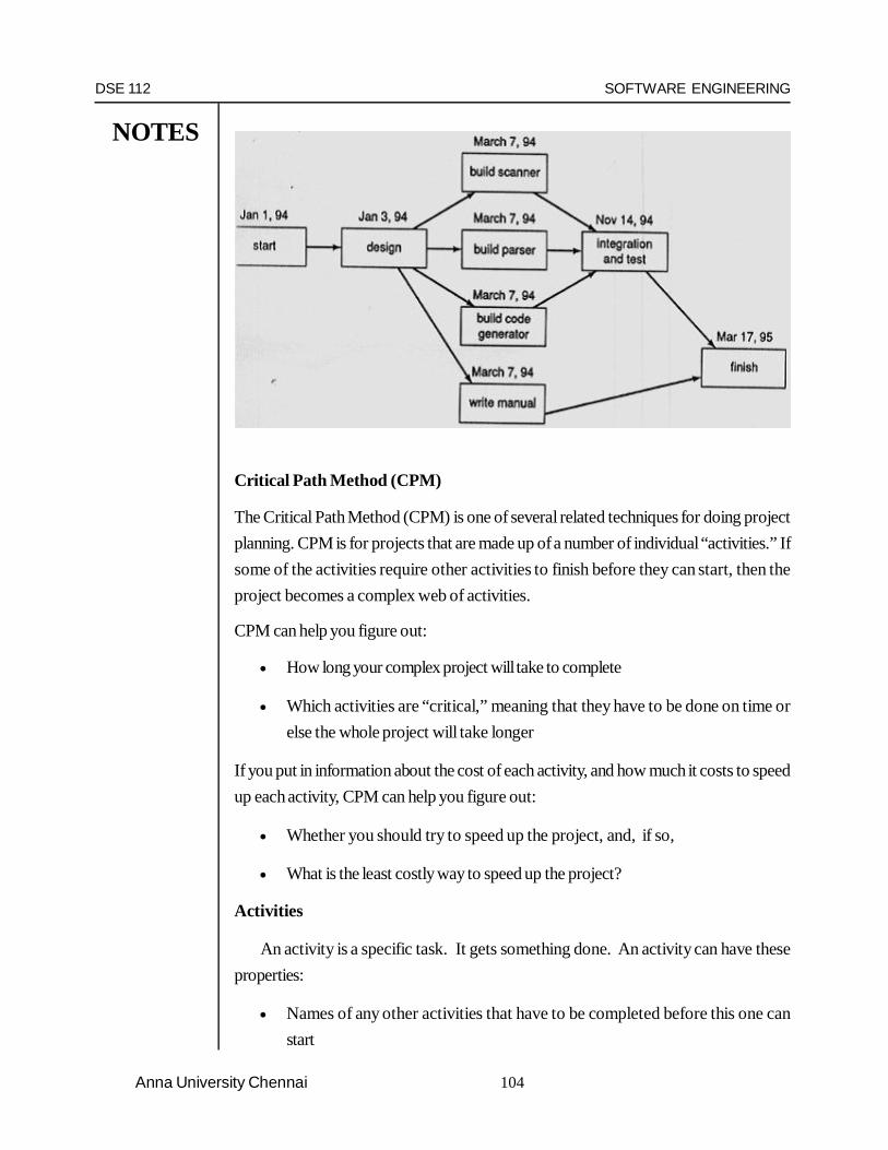
DSE 112 SOFTWARE ENGINEERING
NOTES
104Anna University Chennai
Critical Path Method (CPM)
The Critical Path Method (CPM) is one of several related techniques for doing projectplanning. CPM is for projects that are made up of a number of individual “activities.” Ifsome of the activities require other activities to finish before they can start, then theproject becomes a complex web of activities.
CPM can help you figure out:
How long your complex project will take to complete
Which activities are “critical,” meaning that they have to be done on time orelse the whole project will take longer
If you put in information about the cost of each activity, and how much it costs to speedup each activity, CPM can help you figure out:
Whether you should try to speed up the project, and, if so,
What is the least costly way to speed up the project?
Activities
An activity is a specific task. It gets something done. An activity can have theseproperties:
Names of any other activities that have to be completed before this one canstart

DSE 112 SOFTWARE ENGINEERING
NOTES
105 Anna University Chennai
A projected normal time duration
If you want to do a speedup cost analysis, you also have to know these thingsabout each activity:
A cost to complete A shorter time to complete on a crash basis The higher cost of completing it on a crash basis
CPM analysis starts after you have figured out all the individual activities in your project.
CPM Analysis Steps, By Example
This example describes the steps for doing CPM analysis using an example. Irecommend that you work through the example, so that you can follow the steps.
Activities, precedence, and times
This example involves activities, their precedence (which activities come beforeother activities), and the times the activities take. The objective is to identify the criticalpath and figure out how much time the whole project will take.
Step 1: List the activities
CPM analysis starts when you have a table showing each activity in your project.For each activity, you need to know which other activities must be done before it starts,and how long the activity takes.
Here’s the example:
Activity Description Required Predecessor Duration
A Product design (None) 5 monthsB Market research (None) 1C Production analysis A 2D Product model A 3E Sales brochure A 2F Cost analysis C 3G Product testing D 4H Sales training B, E 2I Pricing H 1J Project report F, G, I 1

DSE 112 SOFTWARE ENGINEERING
NOTES
106Anna University Chennai
Step 2: Draw the diagram
Draw by hand a network diagram of the project that shows which activitiesfollow which other ones. This can be tricky. The analysis method we’ll be using requiresan “activity-on-arc” (AOA) diagram. An AOA diagram has numbered “nodes” thatrepresent stages of project completion. You make up the nodes’ numbers as you constructthe diagram. You connect the nodes with arrows or “arcs” that represent the activitiesthat are listed in the above table.
Some conventions about how to draw these diagrams:
All activities with no predecessor come off of node 1.
All activities with no successor point to the last node, which has to have highestnode number.
In this example, A and B are the two activities that have no predecessor. Theyare represented as arrows leading away from node 1.
J is the one activity that has no successor, in this example. It therefore points tothe last node, which is node 8. If there were more than one activity with successor, allof those activities’ arrows point to the highest number node.
The trickiest part for me of building the above diagram was figuring what to dowith activity H. I had drawn an arrow for activity B coming off node 1 and going tomode 3. I had later drawn an arrow for activity E coming off node 2 and going to node6. Since H requires both B and E, I had to erase my first E arrow and redraw it so itpointed to the same node 3 that B did. H then comes off of node 3 and goes to node 6.

DSE 112 SOFTWARE ENGINEERING
NOTES
107 Anna University Chennai
Having completed the network, it would be very easy for you to now draw thetable and calculate the earliest start time, latest start time, the earliest end time and thelatest end time and the slack. The activities whose slack value is zero are in the criticalpath, meaning that any delay in completing those activities would make the project toslip from its schedule. Hence those activities are much more important and they need tobe taken care properly so that they don’t cause any delay.
Allocate Resources to the Tasks
The first step in building the project schedule is to identify the resources requiredto perform each of the tasks required to complete the project. (Generating projecttasks is explained in more detail in the Wideband Delphi Estimation Process page.) Aresource is any person, item, tool, or service that is needed by the project that is eitherscarce or has little availability.
Many project managers use the terms “resource” and “person” interchangeably,but people are only one kind of resource. The project could include computer resources(like shared computer room, mainframe, or server time), locations (training rooms,temporary office space), services (like time from contractors, trainers, or a supportteam), and special equipment that will be temporarily acquired for the project. Mostproject schedules only plan for human resources—the other kinds of resources arelisted in the resource list, which is part of the project plan.
One or more resources must be allocated to each task. To do this, the projectmanager must first assign the task to people who will perform it. For each task, theproject manager must identify one or more people on the resource list capable of doingthat task and assign it to them. Once a task is assigned, the team member who isperforming it is not available for other tasks until the assigned task is completed. Whilesome tasks can be assigned to any team member, most can be performed only bycertain people. If those people are not available, the task must wait.
Identify Dependencies
Once resources are allocated, the next step in creating a project schedule is toidentify dependencies between tasks. A task has a dependency if it involves an activity,resource, or work product that is subsequently required by another task. Dependenciescome in many forms: a test plan can’t be executed until a build of the software isdelivered; code might depend on classes or modules built in earlier stages; a user interfacecan’t be built until the design is reviewed. If Wideband Delphi is used to generateestimates, many of these dependencies will already be represented in the assumptions.It is the project manager’s responsibility to work with everyone on the engineering

DSE 112 SOFTWARE ENGINEERING
NOTES
108Anna University Chennai
team to identify these dependencies. The project manager should start by taking theWBS and adding dependency information to it: each task in the WBS is given a number,and the number of any task that it is dependent on should be listed next to it as apredecessor. The following figure 3.6 shows the four ways in which one task can bedependent on another.
Figure 3.6: Task Dependencies
Create the Schedule
Once the resources and dependencies are assigned, the software will arrangethe tasks to reflect the dependencies. The software also allows the project manager toenter effort and duration information for each task; with this, it can calculate a final dateand build the schedule.
The most common form for the schedule to take is a Gantt chart. The followingfigure 3.7 shows an example
Figure 3.7: Gantt chart showing the dependencies among the various tasks

DSE 112 SOFTWARE ENGINEERING
NOTES
109 Anna University Chennai
Each task is represented by a bar, and the dependencies between tasks arerepresented by arrows. Each arrow either points to the start or the end of the task,depending on the type of predecessor. The black diamond between tasks D and E is amilestone, or a task with no duration. Milestones are used to show important events inthe schedule. The black bar above tasks D and E is a summary task, which shows thatthese tasks are two subtasks of the same parent task. Summary tasks can contain othersummary tasks as subtasks. For example, if the team used an extra Wideband Delphisession to decompose a task in the original WBS into subtasks, the original task shouldbe shown as a summary task with the results of the second estimation session as itssubtasks.
Q3.4 Questions
1. What is project scheduling2. What are the milestones in scheduling a project? Bring out their importance
with an illustration.3. State the dependencies in project scheduling.4. Explain Gantt in detail with an example.5. Consider the development project for a Travel Agency and try to draw the
project scheduling as an exercise.
3.5 STAFFING AND PERSONNEL PLANNING
Once the project schedule is determined and the effort and schedule of differentphases and different tasks are known, staff requirements can be obtained. From thecost and the overall duration of the project, the average staff size for the project can bedetermined by dividing the total effort by the overall project duration (months)
This average staff size is not detailed enough for proper personnel planning,especially if the variation between the actual staff requirement at different phases islarge. Typically the staff requirement and design, and is the maximum during theimplementation and testing, and then again drops during the final phases of integrationand testing, and then again drops during the implementation and testing, and then againdrops using the final phases of integration and testing. Using the COCOMO model,average staff requirement for the different phases can be determined as the effort andschedule for each phase are known. This presents staffing as a step function with time.

DSE 112 SOFTWARE ENGINEERING
NOTES
110Anna University Chennai
For personnel planning and scheduling, it is useful to have effort and scheduleestimates for the sub systems and basic modules in the system. At the planning time,when the system design has not been done, the planner can only expect to know aboutthe major subsystems in the system, and perhaps the major modules in these subsystems.COCOMO can be used to determine the total effort estimate for different subsystemsor modules.
Detailed cost estimates: An approximate method suitable for small systems isto divide the total schedule in terms of the ratio of the sizes of different components. Amore accurate method, used in COCOMO, is to start with the sizes of differentcomponents (and the total systems). The initial effort for the total system is determined.From this the nominal productivity of the project is calculated by dividing the overallsize by the initial effort. Using this productivity, the effort required for each of the modulesis determined by dividing the size by nominal productivity. This gives an initial effortestimate for the modules. For each module the rating of the different cost driver attributesis determined. From these ratings the effort-adjusted factor (EAF) for each module isdetermined. Using the initial estimates and the EAFs, the final effort estimate of eachmodule is determined. The final effort estimate for the overall system is obtained byadding the final estimates for the different modules.
It should be kept in mind that these effort estimates for a module are done bytreating module like an independent system, thus including the effort required for design,integration, and testing of the module. When used for personal planning this should bekept in mind if the effort for the design and integration phases is obtained separately.
Personnel plan
Once the schedule for different activities and the average staff level for eachactivity is known, the overall personnel allocation for the project can be planned. Thisplan will specify how many people will be needed for the different activities at differenttimes for the duration of the project.
A method for producing the personal plan is to make it a calendar –basedrepresentation, containing all the months in the duration of the project, by listing themonths from the starting date to the ending date. Then for each of the different tasks isidentified, and for which cost and schedule estimates are prepared, list the number of

DSE 112 SOFTWARE ENGINEERING
NOTES
111 Anna University Chennai
people needed in each of the months. The total effort for each month and the total effortfor each activity can easily be computed from this plan. The total for each activity
should be the same as the overall person-months estimate.
Drawing a personnel plan usually requires a few iterations to ensure that theeffort requirement for the different phases and activities is consistent with the estimates
obtained earlier. The ensurence of consistency is made more difficult by the fact that theeffort estimates for individual modules include the design and integration effort for those
modules, and this effort is also included in the effort for these phases. It is usually notdesirable to state staff requirements in a unit less than 0.5 percent in order to make the
plan consistent with the estimates. Some difference between the estimates and the totalsin the personal plan is acceptable.
Team structure
Often a team of people is assigned to a project. For the team to work as a
cohesive group and contribute the most to the project, the people in the team have tobe organized in some manner. The structure of the team has a direct impact on the
product quality and project productivity.
The goals of the group are set by consensus, and input from every member is
taken for major decisions. Group leadership rotates among the group members. Due toits, nature, ego-less teams are sometimes called democratic teams.
The structure allows input from all members, which can lead to better decisions
in difficult problems. This suggests that this structure is well suited for long-term, researchtype projects, which do not have time constraints. On the other hand, it is not suitable
for regular tasks; the communication in democratic structure is unnecessary and resultsin ineffiency.
A chief programmer team, in contrast to ego-less teams, has a hierarchy. It
contains of a chief programmer, who has a backup programmer, a program librarian,and some programmers. The chief programmer is responsible for all major technical
decisions of the project. He does most of the design, and assigns coding of the differentparts of the design to the programmers.

DSE 112 SOFTWARE ENGINEERING
NOTES
112Anna University Chennai
Chief programmer
Back up programmer Librarian ProgrammersFigure 3.8: Chief Programmer Team Structure
A third team structure, called the controlled decentralized team, tries to combinethe strengths of the democratic and chief programmer teams. It consists of a projectleader who has a group of senior programmers under him, while under each seniorprogrammer is a group of junior programmers.
Q3.5 Questions
1. Bring out the importance of staffing and personnel plan.2. Explain how planning of personnel is made during the planning phase of any
project.3. Explain the team structure in detail.4. As an exercise, try to find out the other team structures followed in the corporate
these days.
3.6 SOFTWARE CONFIGURATION MANAGEMENT
Software engineers usually find coding to be the most satisfying aspect of theirjob. This is easy to understand because programming is a challenging, creative activityrequiring extensive technical skills. It can mean getting to “play” with state of the arttools, and it provides almost instant gratification in the form of immediate feedback.Programming is the development task that most readily comes to mind when theprofession of software engineering is mentioned.

DSE 112 SOFTWARE ENGINEERING
NOTES
113 Anna University Chennai
That said, seasoned engineers and project managers realize that programmersare part of a large team. All of the integral tasks, such as quality assurance and verificationand validation, behind-the-scenes activities necessary to turn standalone software intoa useful and usable commodity. Software configuration management (SCM) falls intothis category-it can’t achieve star status, like the latest” killer app “, but it is essential toproject success. The smart software project manager highly values the individuals andtools that provide this service.
This chapter will answer the following questions about software configurationmanagement.
What is Software Configuration Management?
Software Configuration Management (SCM) is the organization of thecomponents of a software system so that they fit together in a working order, never outof synch with each other. Those who have studies the best way to manage theconfiguration of software parts have more elegant responses.
Roger Pressman says that SCM is a “set of activities designed to control changeby identifying the work products that are likely to change, establishing relationshipsamong them, defining mechanisms different versions of these work products, controllingthe changes imposed, and auditing and reporting on the changes made.”
The software Engineering Institute says that it is necessary to establish andmaintain the integrity of the products of the software project throughout the softwarelife cycle. Activities necessary to accomplish this include identifying configuration items/units, systematically controlling changes, and maintaining the integrity and the tracabilityof the configuration throughout the software life cycle.
Military standards view configuration as the functional and/or physicalcharacteristics of hardware/software as set forth in technical documentation and archivesin a product. In identifying the items that need to be configured, we must remember thatall project artifacts are candidates-documents, graphical models, prototypes, code andany internal or external deliverable that can undergo change.
Why is SCM important?
Software project managers pay attention to the planning and execution ofconfiguration management, an integral task, because it facilitates the ability to communicatestatus of documents and code as well as changes that have been made to them. High –

DSE 112 SOFTWARE ENGINEERING
NOTES
114Anna University Chennai
quality released software has been tested and used, making it a reusable asset andsaving development costs. Reused components aren’t free, though-they requireintegration into new products, a difficult task without knowing exactly what they andwhere they are.
CM enhances the ability to provide maintenance support necessary once thesoftware is deployed. If software didn’t change, maintenance wouldn’t exist. Of course,changes to occur. The National Institute of Standards and Technology (NIST) say thatsoftware will be changed to adapt, perfect, or correct it. Pressman points out that newbusiness, new customer needs, reorganizations and budgetary or scheduling constraintsmay lead to software revision.
CM works for the project and the organization in other ways as well. It helpsto eliminate confusion, chaos, double maintenance, the shared data problem, and thesimultaneous update problem, to name but a few issues to be discussed in this chapter.
Who is involved in SCM?
Virtually everyone on a software project is affected by SCM. From the framersof the project plan to the final tester, we rely on it to tell us how to find the object withthe latest changes. During development, when iterations are informal and frequent, littleneeds to be known about a change except what it is, who did it, and where it is. Indeployment and base lining. Changes must be prioritized and the impact of a changeupon all customers must be considered, a change control board (CCB) is the governingbody for modifications after implementations.
How can Software Configuration be implemented in Organization?
Because SCM is such a key tool in improving the quality of delivered products,understanding it and how to implement it in your organization and on your project iscritical success factor. This chapter will review SCM plan templates and provide youwith a composite SCM plan template for use in your projects. We will cover the issuesand basics for a sound software project CM system, including these,
1. SCM principles2. The four basic requirements for an SCM system.3. Planning and organizing for SCM4. SCM tools5. Benefits of SCM6. Path to SCM implementation.

DSE 112 SOFTWARE ENGINEERING
NOTES
115 Anna University Chennai
Configuration Management occurs throughout the Product Development Lifecycle, SCM is an integral task, beginning early in the life cycle. Required from thebeginning of the system exploration phase, the project software configurationmanagement system must be available for the remainder of the project. Fig illustratesthe “when” or SCM on our full product development life cycle.
SCM Principles
Understanding of SCM
An understanding of SCM is critical to the organization attempting to the instituteany system of product control. Understanding through training is a key initial goal, asshown in the pyramid. Executives and management must understand both the benefitsand the cost of SCM to provide the needed support in its implementation. Softwaredevelopers must understand the basics of SCM because they are required to use thetool in building their software products. Without a total understanding, a partialimplementation of SCM with workarounds and back doors will result in disaster for anSCM system.
SCM Plans and Policies
Development of an SCM play policy for an organization and the subsequentplans for each product developed is crucial to successful SCM implementation. PuttingSCM into an organization is a project like any other, requiring resources of time andmoney. There will be specific deliverables and a timeline against which to perform. Thepolicy for the organization lays out in a clear, concise fashion the expectations that theorganizational leadership has for its system. It must lay out the anticipated benefits andthe method to measure the performance to those benefits.
SCM process
The specification processes of SCM are documented for all users to recognize.Not all SCM processes need to be used within an organization or on a product, yet itis important to have available, in “plain sight,” those processes that are used specificallyin your organization. This also maps those processes to how they are implemented.
Metrics
The measures used to show conformance to policy and product plans areimportant details. These measures show where the organization is along the path toreaping the benefits of SCM.

DSE 112 SOFTWARE ENGINEERING
NOTES
116Anna University Chennai
Tools for SCM
The tools used to implement SCM are the next to last item on the pyramid. Fortoo many mangers, this is often the first instead of the fifth stem in SCM –manyorganizations and project simply buy a tool, plop it in place, and expect magic. Actuallyit makes little sense to pick the tools to use in SCM without having done all the previouswork. Putting a tool in place without training, policy or metrics is an exercise in automaticchas. You will simply have an automated way to turn out the wrong product faster.
SCM is an SEI CMM Level 2 key Process Area
The goals for SCM at maturity Level2 are:
Software configuration management activities are planned Selected software work products are identified ,controlled and available Changes to identified software work products are controlled Affected groups and individuals are informed of the status and content of software
baselines.
Questions that assessors might ask include:
Is a mechanism used for controlling changes to the software requirements? Is a mechanism used for controlling changes to the software design Is a mechanism used for controlling changes to the code Is a mechanism used for configuration management of the software tools used
in the development process?
The Four Basic Requirements for an SCM system
1. Identification2. Control3. Audit4. Status accounting
Configuration Identification:
The basic goal of SCM is to manage the configuration of the software as itevolves during development. The configuration of the software is essentially thearrangement or organization of its different functional units or components. Effectivemanagement of the software configuration requires careful definition of the differentbaselines, and controlling the changes to these baselines. Since the baseline consists of

DSE 112 SOFTWARE ENGINEERING
NOTES
117 Anna University Chennai
the SCI s, SCM starts with identification of configuration items. One common practiceis to have only coded modules as configuration items since usually in coding a largenumber of people are involved and the code of one person often depends on the codeof another.
Configuration Control:
The engineering change proposal is the basic document that is used for definingand requesting a change to an SCI. This proposal describes the proposed change, therationale for it, baselines and SCI s that are affected and cost and schedule impacts.
The engineering change proposals are sent to a Configuration Control Board(CCB) .The important factor in configuration control is the procedure for controllingthe changes. Once a engineering change proposal has been approved by the CCB, theactual change in the SCI will occur. The procedures for making these changes must bespecified. Tools can be used to enforce these procedures. One method for controllingthe changes during the coding stages is using program support libraries.
Status Accounting and Auditing
Configuration auditing is concerned with determining how accurately the currentsoftware system implements the system defined in the baseline and the requirementsdocument, and with increasing the visibility and trace ability of software. Auditingprocedures are also responsible for establishing a new baseline. Auditing proceduresmay be different for different baselines.
Configuration Management Plans
SCM plan needs to specify the type of SCI s that will be selected and that thestages during the project where baselines should be established. Note that in the planonly the type of objects that should be selected can be specified: it may not be possibleto identify the exact item, as the item may not exist at the planning time. For example,we can specify that code of any module that is independently unit tested will beconsidered as an SCI. However, we cannot identify the particular modules that willeventually become the SCIs.
Q3.6 Questions
1. What is Software Configuration Management?2. What is the importance of SCM in any project?

DSE 112 SOFTWARE ENGINEERING
NOTES
118Anna University Chennai
3. Who are the personnel involved in SCM?4. Explain in detail the principles of SCM.5. What are the goals of SCM at Maturity Level 2?6. Explain in detail the basic requirements of the SCM system.7. Consider a project of your choice and try to incorporate the SCM activities.
3.7 QUALITY ASSURANCE PLAN
Basic Requirements and Scope
This section defines the requirements of a quality program that the Consultantshall establish, implement and execute before and during the performance of the designcontract to furnish the design, specified materials, baseline survey, design processesand studies that are in conformance with the Design Agreement requirements.
1. The Consultant shall be responsible for providing a quality product to theDepartment under this Agreement. To this end, the Consultant shall have plannedand established a QAP that shall be maintained throughout the term of theAgreement. The elements of the Consultant’s QAP shall be imposed on allentities within the Consultant’s organization.
2. All surveys, design calculations and studies shall be in accordance with standardspecifications for bridge and highway design. Failure of the Consultant to followstandard design practice, unless deviations are specifically described in theAgreement, shall constitute justification for rejection of the work.
3. During the term of the Agreement, the Consultant’s designated Quality AssuranceManager shall perform quality assurance functions. These functions shall includerandom checks of the QAP.
Definitions
Customer - Any internal unit that receives a product or service from the Consultantwhose Quality System is being considered. Customers could also include supervisors,coworkers or management. External customers could include other agencies, politicalofficials, communities or permitting agencies.
Non-conforming Product - Any product produced by the Consultant that does notmeet the established specifications or requirements for quality as outlined in theConsultant’s procedures and Quality Assurance plan. Products could include items

DSE 112 SOFTWARE ENGINEERING
NOTES
119 Anna University Chennai
produced, reports, designs, studies, calculations, letters, memos or services performedfor the customer.
Product - The result of a Consultant’s activities or processes. It may include a serviceprovided to a customer.
Quality Assurance (QA) - The process of checking or reviewing work tasks orprocesses to ensure quality. Personnel independent of the organizational unit responsiblefor the task or process typically conduct this.
All those planned and systematic actions are necessary to provide adequateconfidence that a product or service will satisfy the requirements for quality. QA includesthe development of project requirements that meet the needs of all relevant internal andexternal agencies, planning the processes needed to achieve quality, providing equipmentand personnel capable of performing tasks related to project quality, documenting thequality control efforts, and most importantly, performing checks necessary to verify thatan adequate product is furnished as specified in the Agreement.
Quality Assurance Program - The coordinated execution of applicable Quality ControlPlans and activities for a project.
Quality Assurance Program Plan - A written description of intended actions toachieve quality for the Consultant’s organization.
Quality Control (QC) - The measuring, testing or inspection of a task or process bythe personnel who perform the work.
The Consultant’s operational techniques and activities that are used to fulfillrequirements for quality. These techniques are used to provide a product or service thatmeets requirements. QC is carried out by the operating forces of the Consultant. Theirgoal is to do the work and meet the design goals. Generally, QC refers to the act oftaking measurements and surveys and checking design calculations to meet contractspecifications. Products may be design drawings, calculations, studies or surveys. QCalso refers to the process of documenting such actions.
Quality Management - That aspect of the overall management function that determinesand implements the quality policy.
Quality Oversight (QO) - The administration and review of a Quality Assurance Planto ensure its success.

DSE 112 SOFTWARE ENGINEERING
NOTES
120Anna University Chennai
Activities conducted by the Department to verify the satisfactory implementationof approved Quality Assurance and Quality Control by organizations authorized to doso. QO can range from an informal process of keeping in touch with the QA organizationto a second layer of QA activities, depending upon the circumstances. QO verifies theexecution of the quality program.
Quality Policy - The overall quality intentions and direction of the Consultant’sorganization regarding quality, as formally expressed by the Consultant’s management.
Quality Procedures – the written instructions for implementing various componentsof the organization’s total Quality System.
Management Responsibility
Quality Control Policy
The Consultant’s management with executive responsibilities shall define and documentits policy for quality, including objectives for quality and its commitment to quality.
The quality policy shall be relevant to the Consultant’s organizational goals andthe expectations and needs of the Department. The Consultant shall provide that thispolicy is understood, implemented and maintained within the Consultant’s organization.
Organization
The Consultant shall include a project organization chart that includes qualityassurance and quality control functions. It shall include relationships between projectmanagement, key personnel of Subconsultants, design engineering and quality control.Resumes and responsibilities of the Consultant’s Quality Control staff and its QualityAssurance staff shall be provided.
Responsibility and Authority
The Consultant shall assign an independent Quality Assurance Manager notdirectly responsible for the work to this project that shall manage quality matters for theproject and have the authority to act in all quality matters for the Consultant. The QualityAssurance Manager shall be fully qualified by experience and technical training to performthe quality control activities. The Quality Assurance Manager’s responsibilities shallinclude a method for verifying the implementation of adequate corrective actions for thenon-conforming work and notifying appropriate project management personnel. Aspecific description of the duties, responsibilities and methods used by the Consultant’s

DSE 112 SOFTWARE ENGINEERING
NOTES
121 Anna University Chennai
Quality Assurance staff to identify and correct non-conformities shall be included. Theresume of the Quality Assurance Manager must include a description of his duties,responsibilities, and his record of quality control experience.
The responsibility, authority and interrelation of all personnel who manage,perform and verify work affecting quality shall be defined and documented.
Resource
The Consultant shall identify resource requirements and provide adequateresources, including the assignment of trained personnel, for management, performanceof work and verification activities including internal quality audits.
Quality System
General
The Consultant shall establish, document and maintain a quality assuranceprogram plan as a means of providing a design product that conforms to specifiedrequirements. The quality assurance program plan shall include or make reference tothe work procedures and outline the structure of the documentation used in the qualityassurance program.
Quality Plan Procedures
The Consultant shall prepare documented procedures consistent with therequirements of this section and the Consultant’s or Subconsultant’s stated quality policy.Documented procedures may make reference to work instructions that define how anactivity is performed.
Quality Planning
The Consultant shall define and document how the requirements for quality willbe met. Quality planning shall be consistent with all other requirements of a Consultant’sQuality Assurance Program and shall be documented in a format to suit the Consultant’smethods of operation.
Agreement Review
The Consultant shall establish and maintain documented procedures forAgreement reviews and for the coordination of all applicable activities, to verify that theservices meet the requirements.

DSE 112 SOFTWARE ENGINEERING
NOTES
122Anna University Chennai
Review and Amendment to Agreement
The Consultant shall review and concur with all Agreement commitments priorto the execution of the Agreement. The Consultant shall also establish the responsibilitiesfor coordinating and conducting Agreement reviews, distribution of documents for review,and the process for identifying and amending discrepancies within the Agreement.
Records
Records of Agreement reviews and amendments shall be maintained and madeaccessible to personnel directly involved in the review process, in accordance with theterms of the Agreement.
Design Control
General
The Consultant shall establish and maintain documented procedures to controland verify that the design meets the specified requirements.
Design Input
A framework for initial design planning activities shall be established. The designershall compile record and verify information on field surveys and inspections. All relevantdesign criteria, including codes and standards, shall be established and made availableto design personnel. Design schedules and design cost estimates shall be monitoredand adhered to, with documentation of any deviations. A documented procedure forresponding to all comments from the units, which have been coordinated by the ProjectManager, shall be established.
Design Output
The designer shall establish methods and implement reviews to determine thatcompleted designs are constructable, functional, meet the requirements and conform toestablished regulatory standards. Furthermore, the Consultant shall establish andimplement procedures to determine that only the most recent revisions to writtenprocedures, codes, standards and relevant documents are used.
Design Changes
Before their implementation, all design changes and modifications shall beidentified, documented, reviewed and reported for approval.

DSE 112 SOFTWARE ENGINEERING
NOTES
123 Anna University Chennai
Organizational and Technical Interfaces
Organizational and technical communication interfaces between different groupsthat input into the design process shall be defined and the necessary informationdocumented, transmitted and regularly reviewed. These groups shall include theConsultant, outside agencies and any Sub consultants.
Document Control
General
The Consultant shall establish and maintain documented procedures to controlall documents and data that relate to the requirements of this section including, to theextent applicable, documents of external origin such as studies, reports, calculations,standards and record drawings. These procedures shall control the generation,distribution and confidentiality of all documents, as well as establish a system to identify,collect, index, file, maintain and dispose of all records. Documents and data can be inthe form of any media, such as hard copy or electronic media.
Document and Data Approval and Issue
The documents and data shall be reviewed and approved for adequacy byauthorized personnel prior to issue. A master list or equivalent document control procedureidentifying the current revision status of documents shall be established and be readilyavailable to preclude the use of invalid and/or obsolete documents.
Document and Data Changes
Changes to documents and data shall be reviewed and approved by the samefunctions or organizations that performed the original review and approval, unlessspecifically designated otherwise. The designated functions or organization shall haveaccess to pertinent background information upon which to base their review andapproval.
Where practical, the nature of the change shall be identified in the document orthe appropriate attachments.
Control of Sub consultants
General
The Consultant shall establish and maintain documented procedures to providesubcontracted or purchased services that conform to specified requirements.

DSE 112 SOFTWARE ENGINEERING
NOTES
124Anna University Chennai
Evaluation of Sub consultants
The Consultant shall:
a. Select subconsultants on the basis of their ability to meet agreement requirementsand any specific quality control requirements. The sub consultant shall be requiredto accept and implement the consultant’s QAP or to submit their own for reviewand approval by the consultant
b. Define the type and extent of control exercised by the consultant over subconsultants. Include a description of the system used to review and monitor theactivities and submissions of the sub consultant. This control shall be dependentupon the type of service, the impact of a subcontracted service on the quality ofthe final design and, where applicable, dependent on the quality audit reportsand/or quality records of the sub consultants
c. Review quality records of subconsultants consisting of quality control and qualityassurance data for the project
Design Product Identification and Traceability
Where appropriate, the consultant shall establish and maintain documentedprocedures for identifying its design product by suitable means from its inception andduring all stages of development, design and delivery.
Where and to the extent that traceability is a specified requirement, the consultantshall establish and maintain documented procedures for unique identification of individualdesign products. This identification shall be recorded
Control of Department Supplied Product
The consultant shall establish and maintain documented procedures for the controlof, verification, storage and maintenance of the supplied products, such as recorddrawings or special equipment, provided for incorporation into the contract or for relatedactivities. Any such product that is lost, damaged, or is otherwise unsuitable for useshall be recorded and reported.
Process Control
The Consultant shall identify and plan the design, survey, research or servicingprocesses which directly affect quality and shall carry out these processes undercontrolled conditions. Controlled conditions shall include the following:

DSE 112 SOFTWARE ENGINEERING
NOTES
125 Anna University Chennai
a. Documented procedures defining the manner of design, survey, research orservicing, where the absence of such procedures could adversely affect quality;
b. Use of suitable design, survey, research or servicing equipment, and a suitableworking environment;
c. Compliance with referenced standards/codes, quality plans and/or documentedprocedures;
d. Monitoring and control of suitable process parameters and end productcharacteristics;
e. The approval of special processes and equipment, if applicable;
f. Criteria for workmanship, which shall be stipulated in the clearest practicalmanner (e.g., written standards, representative samples or illustrations);
g. Suitable maintenance of equipment, if applicable, to provide continuing processcapability;
h. A detailed description of unique procedures.
The requirements for any qualification of special survey or research work,including the associated equipment and personnel.
Corrective and Preventive Action
General
The Consultant shall document procedures to be utilized to implement correctiveand preventive action.
Corrective or preventive action taken to eliminate actual or minimize potentialdesign non-conformities shall be to a degree appropriate to the magnitude of problemsand commensurate with the risks encountered.
The Consultant shall implement and record any changes to the documentedprocedures resulting from corrective and preventive action.
Corrective Action
The corrective action procedures to eliminate actual non-conforming designproducts shall include:

DSE 112 SOFTWARE ENGINEERING
NOTES
126Anna University Chennai
a. The effective handling of observations and reports of design product non-conformities, including developing interim measures, if warranted, to correctthe actual non-conformity;
b. Conducting an investigation into the root cause of non-conformities relating tothe design product, process and quality system, and recording the results of theinvestigation
c. Determination of the corrective action needed to eliminate the cause of thedesign non-conformities;
d. Application of measures to determine that corrective action has been takenand that it is effective.
Preventive Action
The procedures for preventive action to minimize nonconformities shall include:
a. The use of appropriate sources of information relating to the quality of thedesign product (such as concessions, audit results, quality records, servicereports and complaints) to detect, analyze, and eliminate potential causes ofnonconformities;
b. Determination of the steps needed to deal with any problems requiring preventiveaction;
c. Initiation of preventive action and appropriate follow-up reviews to determinethat it is effective;
d. Confirmation that relevant information on actions taken is submitted for theconsultant management review.
Control of Quality Records
The Consultant shall establish and maintain documented procedures foridentification, collection, indexing, access, filing, storage, maintenance, and dispositionof quality records. Records may be in the form of any type of media, such as hard copyor electronic media.
Quality records shall be maintained to demonstrate conformance to specifiedrequirements and the effective operation of the quality system. Pertinent quality recordsfrom the Sub consultant shall be an element of these data.

DSE 112 SOFTWARE ENGINEERING
NOTES
127 Anna University Chennai
All quality records shall be legible and shall be retained in such a way that theyare readily retrievable in files that provide a suitable environment to prevent damage,deterioration or loss. Where agreed contractually, quality records shall be made availablefor evaluation for an agreed period.
Internal Quality Audits
The Consultant shall establish and maintain documented procedures for planningand implementing internal quality audits to verify whether quality activities and relatedresults comply with planned arrangements and to determine the effectiveness of thequality system.
Internal quality audits shall be scheduled on the basis of the status and importanceof the activity to be audited and shall be carried out by personnel independent of thosehaving direct responsibility for the activity being audited.
The results of the audits shall be recorded and brought to the attention of thepersonnel having responsibility in the area audited. The management personnelresponsible for the area shall take timely corrective action on deficiencies found duringthe audit.
Follow-up audit activities shall verify and record the implementation andeffectiveness of the corrective action taken.
Training
The Consultant shall establish and maintain documented procedures foridentifying training needs and provide for the training of all personnel performing activitiesaffecting quality. Personnel performing specific assigned tasks shall be qualified on thebasis of appropriate education, training and/or experience, as required. Appropriaterecords of training shall be maintained
Servicing of the Design Product
Where servicing of the Consultant’s design product is a specified requirement,the Consultant shall establish and maintain documented procedures for performing,verifying, and reporting that the servicing meets the specified requirements. Servicing ofa design product, for example, may include providing for field visits to investigateconstruction problems or providing related engineering support until the project iscomplete.
DSE 112 SOFTWARE ENGINEERING
NOTES
128Anna University Chennai
Statistical Techniques
Identification of Need
The Consultant shall identify the need for statistical techniques required forspecial survey or research projects, if applicable.
Procedures
The Consultant shall establish and maintain documented procedures to implementand control the application of the statistical techniques.
Handling, Storage, Packaging, Preservation and Delivery
General
The Consultant shall establish and maintain documented procedures for handling,storage, packaging, and delivery of the final design, survey or research product.
Handling
The Consultant shall provide methods of handling its final design, survey orresearch product to minimize damage, deterioration, loss or incorrect identification.
Storage
The Consultant shall use designated areas or files to minimize damage ordeterioration to documents, plans, studies or reports prior to use or delivery. Appropriatemethods for authorizing receipt to and dispatch from such areas shall be stipulated.
Packaging
The Consultant shall control packaging and labeling processes to the extentnecessary to conform to specified requirements.
Preservation
The Consultant shall apply appropriate methods for preservation and segregationof the documents, plans, studies or reports when they are under its control.
Delivery
The Consultant shall arrange for the protection of the documents, plans, studiesor reports after final checking. Where contractually specified, this protection shall beextended to include delivery to the destination.

DSE 112 SOFTWARE ENGINEERING
NOTES
129 Anna University Chennai
Contractor’s Quality Assurance and Management System
Contractor’s Quality Assurance and Management System (herein after referredto as the “QA System”) shall comply with the requirements of ISO 9001 for workassociated with design and ISO 9002 for manufacturing and construction work.Contractor shall maintain effective control of the quality of the Work, provide test facilitiesand perform all examinations and tests necessary to demonstrate conformance of theWork to the requirements of the Contract and shall offer for acceptance only thoseaspects of the Work that so conform. Contractor shall be responsible for the provisionof Objective Evidence that Contractor’s controls and inspections are effective. For thispurpose “Objective Evidence” means any statement of fact, quantitative or qualitative,pertaining to the quality of the Work based on observations, measurements or testswhich can be verified.
Quality System Documentation
At a minimum, the following documents shall be provided for surveillance ofQuality System during execution of the Contract:
1. Quality Manual2. Quality Plan3. Schedule of Quality Records
The Quality Plan shall include:
a) A policy statement identifying the quality system to be implemented for the Contract;b) Management responsibilities specific to the Contract including the responsibility
and authority for quality;c) The organization proposed for the Contract;d) An outline of procedures for reviewing, updating and controlling the Quality Plan
and referenced documentation;e) Quality System implementation plan;f) Reference to technical/quality features peculiar to the Contract;g) Method by which Contractor intends to control quality and complete the Work;h) Contractor’s method of control of sub-contract work;i) Details of special processes and control procedures;j) Details of design verification activities to be performed, including the methods to be
employed to control design and the Design and Documentation Plan; andk) Details of the quality records to be taken and maintained by Contractor.

DSE 112 SOFTWARE ENGINEERING
NOTES
130Anna University Chennai
Quality Verification
Contractor is responsible for ensuring that work (including subcontracts) deliveredas part of the Contract meet all the technical and quality requirements.
a) Contractor shall provide the work as specified in the contract, together withdocumented evidence that the work conform to the requirements.
b) Contractor shall provide the work, as specified in the contract, together withinspection reports and/or certificates of adequacy and compliance from a suitablyqualified person, certifying the sufficiency, serviceability and integrity of the work.
Q 3.7 Questions
1. What are the basic requirements of the Quality Assurance Plans?2. Explain the terms customer, product, and non-confirming product in the context of
QA.3. Explain sub consultants control.4. What is the importance of corrective and preventive actions?5. Explain the term Quality Control Policy.6. Explain in detail the Quality Assurance.7. Explain in detail the Quality System and Quality Plan Procedure8. Explain in detail design control, documentation control and process control9. Write short notes on Responsibility and Authority, Reviews and Internal Quality
Audits.10. Explain the term “Contractor’s Quality Assurance and Management System” in
detail.11. Explain Quality System Documentation in detail.12. Write the Quality Document for any real time application of your choice.
3.8 RISK MANAGEMENT
In this chapter we are concerned with the risk of the development project’s notproceeding according to plan. We are primarily concerned with the risks of the projectsrunning late or over budget and with the identification of the steps that can be taken toavoid or minimize those risks.
Some risks are more important than others .Whether or not a particular risk isimportant depends on the nature of the risk, its likely effects on a particular activity and

DSE 112 SOFTWARE ENGINEERING
NOTES
131 Anna University Chennai
the criticality of the activity. High risk activities on a projects critical path are a cause forconcern
To reduce these dangers, we must ensure that risks are minimized or, at least ,distributed over the project and ideally removed from critical path activities.
The risk of an activities running over time is likely to depend , at least in part onwho is doing or managing it. Evaluation of risk and the allocation of staff and otherresources are therefore closely connected.
The nature of risk;
For the purpose of identifying and managing those risks that may cause a projectto overrun its time-scale or budget, it is convenient to identify three types of risk:
Those caused by the inherent difficulties of estimation Those due to assumptions made during the planning process Those of unforeseen event occurring
Estimation Errors:
Some tasks are harder to estimate than others because of the lack of experienceof similar tasks or because of the nature of the task. Producing a set of user manuals isreasonably straightforward and given, that we have carried out similar tasks previously,we should be able to estimate with some degree of accuracy how long it will take andhow much it will cost. On the other hand, the time required for program testing anddebugging, might be difficult to predict with a similar degree of accuracy –even if wehave written similar programs in the past.
Planning Assumptions
At every stage during planning, assumptions are made which if not valid mayput the plan at risk Our activity network for example, is likely to be built on the assumptionof using a particular design methodology which may be subsequently changed. Wegenerally assume that following coding a module will be tested and then integrated withothers. We might not plan for module testing showing up the need for changes in theoriginal design but in the event if might happen.
At each stage in the planning process, it is important to list explicitly all of theassumptions that have been made and identity what effects they might have on the planif they are inappropriate.

DSE 112 SOFTWARE ENGINEERING
NOTES
132Anna University Chennai
Eventualities:
Some eventualities might never be foreseen and we can only resign ourselvesto the fact that unimaginable thing to, sometimes happen. They are however very rate.The majority of unexpected events can., in fact, be identified –the requirementsspecification might be altered after some of the modules have been coded, the seniorprogrammer might take maternity leave, the required hardware might not be deliveredon time. Such events do happen from time to time and although the likelihood of anyone of them happening during a particular project may be relatively low, they must beconsidered and planned for.
Managing risk
The objectives of risk management are to avoid or minimize the adverse effectsof unforeseen events by avoiding the risks or drawing up contingency plans for dealingwith them.
There are number of models for risk management, but most are similar, in thatthey identify two main components – risk identification and risk management.
Risk identification consists of listing all of the risks that can adversely affect thesuccessful execution of the project.
Risk estimation consists of assessing the likelihood and impact of each hazard.
Risk evaluation consists of ranking the risks and determining risk aversion strategies.
Risk planning consists of drawing up contingency plans and where appropriate, addingthese to the projects task structure. With small projects risk planning is likely to be theresponsibility of the project manager but medium or large projects will benefit from theappointment of a full time risk manager
Risk control concerns the main functions of the risk manager in minimizing and reactingto problems throughout the project. This function will include aspects of quality controlin addition to dealing with problems as they occur.
Risk monitoring must be an ongoing activity, as the importance and likely hood ofparticular risks can change as the project proceeds.

DSE 112 SOFTWARE ENGINEERING
NOTES
133 Anna University Chennai
Risk directing and risk staffing are concerned with the day to day management ofrisk. Risk aversion and problem solving strategies frequently involve the use of additionalstaff and this must be planned for and directed.
Risk identification
The first stage in any risk assessment exercise is to identify the hazards thatmight affect the duration or resource costs of the project. A hazard is an event thatmight occur and will, if it does occur create a problem for the successful completion ofthe project. In identifying and analyzing risks, we can usefully distinguish between thecause, its immediate effect and risk that will pose to the project.
For example the illness of a team member is a hazard that might result in theproblem of late delivery of a component. The late delivery of that component is likelyhave an effect on other activities and might, particularly if it is on the critical path, put theproject completion date at risk.
A common way of identifying hazards is to use a checklist listing all the possiblehazards and factors that influence them. Typical checklists may, even hundreds of factorsand there are, today a number of knowledge based software products available toassist in this analysis.
Some hazards are generic risks, that is they are relevant to all software projectsand standard checklists can be used and augmented from an analysis of past projectsto identify them,
The categories of factors that will need to be considered include the following.
Application factors the nature of the application-whether it is a simple data processingapplication, a safety critical system or a large distributed system with real time elements-is likely to be a critical factor. The expected size of the application is also important-thelarger the system, the greater is the likelihood of errors and communication andmanagement problems
Staff factors the experience and skills of the staff involved are clearly major factors anexperienced programmer is , one would hopeless likely to make errors than one withlittle experience-experience in coding small data processing modules in Cobal may belittle value if we are developing a complex real time control system using C++

DSE 112 SOFTWARE ENGINEERING
NOTES
134Anna University Chennai
Project factors are important that the project and its objectives are well defined andthat they are absolutely clear to all members of the project team and all key stakeholders.Any possibility that this is not the case will pose a risk to the success adhered to by allparticipants and any possibility that the quality plan is inadequate or not adhered to willjeopardize the project.
Project methods using well specified and structured methods for project managementand system development will decrease risk of delivering a system that is unsatisfactoryor later. Using such methods for the first time, through may cause problems and delays–it is only with experience that the benefits accrue.
Hardware/software factors a project that requires new hardware for development islikely to pose a higher risk than one where the software can be developed on existinghardware where a system is developed on one type of hardware or software platformto be used on another there might be additional risks at instillation
Changeover factors the need for an all in one changeover to the new system posesparticular risks. Incremental or gradual changeover minimizes the risks involved but isnot always practical. Parallel running can provide a safety net but might be impossibleor too costly
Supplier factor the extent to which a project relies on external organizations that cannotbe directly controlled often influences the projects success. Delays in for example theinstallation of telephone lines of delivery of equipment may be difficult to avoid –particularly if the project is of little consequence to the external supplier
Environment factors changes in the environment can affect a project’s success. Asignificant change in the taxation regulations could, for example, have seriousconsequences for the development of a payroll application.
Health and safety factors While for generally a major issue for software projects,the possible effects of project activities on the health and safety of the participants andthe environment should be considered.
Risk analysis
Having identified the risks that might affect our project we need some way ofassessing their importance. Some risks will be relatively unimportant whereas some willbe major significance. Some are quite likely to occur.

DSE 112 SOFTWARE ENGINEERING
NOTES
135 Anna University Chennai
The probability of a hazards occurring is known as risk likelihood; the effectthat the resulting problem will have on the project, if its occurs, is known as the riskimpact and the importance of the risk is known as risk value or risk exposure. The riskvalue is calculated as:
Risk exposure =risk likelihood * risk impact
Ideally the risk impact is estimated in monetary terms and the likelihood assessedas a probability. In that case the risk exposure will represent an expected cost in thesame sense that we calculated expected costs and benefits when discussing cost benefitanalysis. The risk exposure for various risks can then be compared with each other toassess the relative importance of each risk and they can be directly compared with thecosts and likelihoods of success of various contingency plans.
Many risk managers use a simple scoring method to provide a quantitativemeasure for assessing each risk. Some just categorize likelihoods and impacts as high,medium or low. But this form of ranking does not allow the calculation of a risk exposure.A better and popular approach is to score the likelihood and impact on a scale of, say1 to 10 where the hazard that is most likely to occur receives a score of 10 and the leastlikely a score of 1.
Ranking likelihoods and impacts on a scale of 1 to 15 is relatively easy butmost risk mangers will attempt to assign scores in a more meaningful way.
Impact measures scored on a similar scale, must take into account the total riskto the project. This must include the following potential costs:
The cost of delays to scheduled dates for deliverables
Cost overruns caused by using additional and more expensive resources
The costs incurred or implicit in any compromise to the systems quality orfunctionality
Prioritizing the risks
Managing risk involves the use of two strategies:
Reducing the risk exposure by reducing the likelihood or impact
Drawing up contingency plans to deal with the risk should occur

DSE 112 SOFTWARE ENGINEERING
NOTES
136Anna University Chennai
Any attempt to reduce a risk exposure or put a contingency plan in place willhave a cost associated with it. It is therefore important to ensure that this effort isapplied in the most effective way and we need a way of prioritizing the risks so that themore important ones can receive the greatest attention.
Estimate values for the likelihood and impact of each of these terms and calculatetheir risk exposures.
Rank each of your risks according to their risk exposure and try to categorizeeach of them as high medium or low priority.
In practice there are generally other factors, in addition to the risk exposurevalue that must also be taken into account when prioritizing risks.
Confidence of the risk assessment Some of our risk exposure assessments will berelatively poor. Where there is the case, there is a need for further investigation beforeaction can be planned.
Compound risks Some risks will be dependant on others. Where this is the case, theyshould be treated together as a single risk
The number of risks There is a limit to the number of risks that can be effectivelyconsidered and acted on by a project manager. We might therefore wish to limit the sizeof the prioritized list.
Cost of action. Some risks once recognized can be reduced or avoided immediatelywith very little cost of effort and it is sensible to take action on these regardless of theirrisk value. For other risks we need to compare the costs of taking action with thebenefits of reducing the risk. One method for doing this is to calculate the Risk ReductionLeverage (RRL) using the equation
RRL = (REbefore - REafter) / (Risk reduction cost)
Where RE before is the original risk exposure value. REafter is the expected risk exposurevalue after taking action and the risk reduction cost is the cost of implementing the riskreduction action Risk reduction costs must be expressed I n the same units as riskvalues-that is, expected monetary values than the RRL greater than one indicate thatwe can expect to gain from implementing the risk reduction plan because the expectedreduction in risk exposure is greater than the cost of the plan.

DSE 112 SOFTWARE ENGINEERING
NOTES
137 Anna University Chennai
Reducing the risks
Broadly, there are five strategies for risk reduction
Hazard prevention Some hazards can be prevented from occurring or their likelihoodreduced to in significant levels. The risk of key staff being unavailable for meetings canbe minimized by early scheduling.
Likelihood reduction Some risks while they cannot be prevented can have theirlikelihoods reduced by prior planning. The risk of late changes to a requirementsspecification can, for example, be reduced by prototyping.
Risk avoidance A project can, for example, be projected from the risk of overrunningthe schedule by increasing duration estimates or reducing functionality.
Risk transfer The impact of some risks can be transferred away from the project, byexample contracting out or taking out insurance,
Contingency planning Some risks are not preventable and contingency plans willneed to be drawn up to reduce the impact should the hazard occur. A project managershould draw up contingency plans for using agency programmers to minimize the impactof any unplanned absence of programming staff.
Table 3.4: Software projects risks and strategies for risk reduction
Risk Risk reduction techniques
Personnel shortfalls Staffing with top talent; job matching; team building;training and career development; early scheduling ofkey personal
Unrealistic time and cost Multiple estimation techniques; design to cost; incrementalestimates development; recording and analysis of past projects;
standardization of methods
Developing the wrong Improved project evaluation; formal specificationsoftware functions methods; user surveys ; prototyping ;early users manuals
Developing the wrong user Prototyping; task analysis; user involvement.interface

DSE 112 SOFTWARE ENGINEERING
NOTES
138Anna University Chennai
Gold plating Requirements scrubbing ;prototyping; cost-benefitanalysis; design to cost
Late changes to requirements Stringent change control procedure; high changethreshold ;incremental prototyping; incrementaldevelopment(defect change)
Short fails in external Benchmarking; inspections; formal specifications;supplied contents contractual agreements ;quality assurance procedures
and certification
Shortfalls in externally Quality assurance procedures; competitive design orperformed tasks prototyping ;teambuilding ;contract incentives
Evaluating risks to the schedule
We have seen that not all risks can be eliminated –even those that are classifiedas avoidable or manageable can, in the event, still cause problems affecting activitydurations .By identifying and categorizing those risks, and in particular, their likely effectson the duration of planned activities, we can assess what impact they are likely to haveon our activity plan
Using PERT to evaluate the effects of uncertainty
PERT was developed t take account of the uncertainty surrounding estimatesof task durations. It was developed in an environment of expensive, high risk and stateof are projects –not that dissimilar to many of today’s large software projects.
The methods of very similar to the CPM technique but, instead of using a singleestimate for the duration of each task, PERT requires three estimates.
Most likely time- the time we would expect the take to take under normal circum-stances, we shall denote this by letter m
Optimistic time-t he shortest time in which we could expect to complete the activity,barring outright miracles, we shall use the letter a to denote this
Pessimistic time-the worst possible time allowing for all reasonable eventualities butexcluding ‘acts of God and war face’

DSE 112 SOFTWARE ENGINEERING
NOTES
139 Anna University Chennai
PERT then combines these three circumstances to form a single expected
duration, the using the formula
Te= a +4m+b / 6
Using expected durations:
The expected durations are used to carry out a forward pass through a net-
work: using the same method as the CPM technique, In this case, however, the calcu-
lated even dates not the earliest possible dates but are the dates by which we expect to
achieve those events.
Having studied the Software cost, effort and schedule estimation, the tech-
niques used to this estimation, the SCM and Software Quality Assurance in brief, the
next step of the SDLC is the Design phase. The various topics on software design such
as the software design principles, software design methodologies and the design vali-
dation and metrics are discussed in the next unit.
Q3.9 Questions
1. Explain the following terms.
a. Most likely time
b. Optimistic time
c. Pessimistic time
2. What are the various ways of reducing the risks?
3. Explain the term RRL.
4. How does one prioritize the risks?
5. What is risk impact?
6. What is risk exposure?
7. Write a note on risk analysis.
8. What are the various factors that cause risks?
9. Explain in detail the Risk Management.
10. How are the risks identified? Explain in detail.
11. Explain PERT in detail with an example.

DSE 112 SOFTWARE ENGINEERING
NOTES
140Anna University Chennai
REFERENCES
1. Software Engineering A Practitioner’s Approach, By Roger. S.Pressman, Mc
Graw Hill International 6th edition, 2005.
2. Software Project Management, 4th Edition by Bob Hughes and Mike
Cotterell.
3. http://www.netmba.com/operations/project/cpm/
4. http://www.sce.carleton.ca/faculty/chinneck/po/Chapter11.pdf
5. http://www.netmba.com/operations/project/pert/
6. http://www.cs.utsa.edu/~niu/teaching/cs3773Spr07/SoftPlan.pdf

DSE 112 SOFTWARE ENGINEERING
NOTES
141 Anna University Chennai
UNIT IV4 INTRODUCTION
The design of any software system is one of the tedious processes as there areseveral strategies, concepts that go into it. There are many paradigms for the softwaredesign. Here we would be discussing on the various strategies of designs, approaches,verification and metrics for measuring their effectiveness.
4.1 LEARNING OBJECTIVES
1. What is function-oriented design?2. What are the design principles?3. Module level concepts – coupling and cohesion.4. Structured design methodology5. Module Specifications.6. Detailed design7. Design Verification and design metrics.
4.2 FUNCTION-ORIENTED DESIGN
It is the design with functional units, which transform inputs to outputs
Objectives
1. To explain how a software design may be represented as a set of functionswhich share state
2. To introduce notations for function-oriented design3. To illustrate the function-oriented design process by example
This approach has been practiced informally since programming began andthousands of systems have been developed using this approach. Supported directly bymost programming languages Most design methods are functional in their approach

DSE 112 SOFTWARE ENGINEERING
NOTES
142Anna University Chennai
CASE tools are available for design support. The function oriented view of softwaredesign is given in the figure 4.1 shown below.
Figure 4.1: A function-oriented view of Design
Structured System Analysis and Design and Object Oriented Analysis andDesign
The SSAD and OOAD are the two main approaches followed in thedevelopment of the system. The following section gives the difference between theSSAD and the OOAD.
The difference between the Structured System Analysis and Design and ObjectOriented Analysis and Design can be done as an exercise.
Functional and Object-Oriented Design
1. For many types of application, object-oriented design is likely to lead to amore reliable and maintainable system
2. Some applications maintain little state - function-oriented design is appropriate3. Standards, methods and CASE tools for functional design are well-established4. Existing systems must be maintained - function-oriented design will be practiced
well.
Functional design process
The functional design process consists of the following;
F5
Shared Memory
F2 F3
F4
F1

DSE 112 SOFTWARE ENGINEERING
NOTES
143 Anna University Chennai
1. Data-flow designa. Model the data processing in the system using dataflow diagrams
2. Structural decompositionb. Model how functions are decomposed to sub-functions using graphical
structure chartsData-flow design
The following figure 4.2 gives the notations used in the design using the DataFlow Diagrams (DFD)
Figure 4.2: DFD Notations
Data Flow Diagrams (DFDs) are a graphical/representation of systems andsystems components. They show the functional relationships of the values computedby a system, including input values, output values, and internal data stores. It’s a graphshowing the flow of data values from their sources in objects through processes/functionsthat transform them to their destinations in other objects. Some use a DFD to showcontrol information, others might not.
Steps for Developing DFDs
1. Requirements determination2. Divide activities3. Model separate activities4. Construct preliminary context diagram5. Construct preliminary System Diagram/ Level 0 diagrams - As far as I expect
for starting students to get.6. Deepen into preliminary level n diagrams (primitive diagrams in text)7. Combine and adjust separate level-0 to level-n diagrams8. Combine level-0 diagram into definitive diagram9. Complete diagrams

DSE 112 SOFTWARE ENGINEERING
NOTES
144Anna University Chennai
Step 1: Requirements determination
This is the result of the preceding phases. Through different techniques, theanalyst has obtained all kinds of specifications in natural language. This phase neverstops until the construction of the DFD is completed. This is also a recursive phase. Atthis moment, he should filter the information valuable for the construction of the dataflow diagram.
Step 2: Divide activities
The analyst should separate the different activities, their entities and their requireddata. The completeness per activity can be achieved by asking the informant the textualspecification with the lacking components in the activity.
Step 3: Model separate activities
The activities have to be combined with the necessary entities and data storesinto a model where input and output of an activity, as well the sequence of data flowscan be distinguished. This phase should give a preliminary view of what data is wantedfrom and given to whom.
Step 4: Construct preliminary context diagram
The organization-level context diagram is very useful to identify the differententities. It gives a steady basis in entity distinction and name giving for the rest of theconstruction. From here on, the analyst can apply his top-down approach and start astructured decomposition.
Step 5: Construct preliminary level 0 diagrams
The overview, or parent, data flow diagram shows only the main processes. Itis the level 0 diagram. This diagram should give a ‘readable’ overview of the essentialentities, activities and data flows. An over-detailed level 0 diagram should generalizeappropriate processes into a single process.
Step 6: Deepen into preliminary level n diagrams
This step decomposes the level 0 diagrams. Each parent process is composedof more detailed processes, called child processes. The most detailed processes, whichcannot be subdivided any further, are known as functional primitives. Processspecifications are written for each of the functional primitives in a process.

DSE 112 SOFTWARE ENGINEERING
NOTES
145 Anna University Chennai
Step 7: Combine and adjust level 0-n diagrams
During the structured decomposition, the creation of the different processesand data flows most often generate an overlap in names, data stores and others. Withinthis phase, the analyst should attune the separate parent and child diagrams to eachother into a standardized decomposition. The external sources and destinations for aparent should also be included for the child processes.
Step 8: Combine level 0 diagrams into a definitive diagram
The decomposition and adjustment of the leveled diagrams will most oftenaffect the quantity and name giving of the entities.
Step 9: Completion
The final stage consists of forming a structured decomposition as a whole. Theinput and output shown should be consistent from one level to the next. The result ofthese steps, the global model, should therefore obey all the decomposition rules.
Table 4.1: Some DFD rules
Overall: 1. Know the purpose of the DFD. It determines the level ofdetail to be included in the diagram.
2. Organize the DFD so that the main sequence of actionsreads left to right and top to bottom.
3. Very complex or detailed DFD’s should be levelled.
Processes: 4. Identify all manual and computer processes (internal to thesystem) with rounded rectangles or circles.
5. Label each process symbol with an active verb and thedata involved.
6. A process is required for all data transformations andtransfers. Therefore, never connect a data store to a datasource or destination or another data store with just a dataflow arrow.
7. Do not indicate hardware or whether a process is manualor computerized.
8. Ignore control information (if’s, and’s, or’s).
Data flows: 9. Identify all data flows for each process step, except simplerecord retrievals.

DSE 112 SOFTWARE ENGINEERING
NOTES
146Anna University Chennai
10. Label data flows on each arrow.
11. Use data flow arrows to indicate data movement, not non-data physical transfers.
Data stores: 12. Dot not indicates file types for data stores.
13. Draw data flows into data stores only if the data store willbe changed.
External entities: 14. Indicate external sources and destination of data, whenknown, with squares.
15. Number each occurrence of repeated external entities.
16. Do not indicate persons or places as entity squares whenthe process is internal to the system.
Context Diagram
It very briefly explains the system to be designed as to what is the system input,the system process and the system output. It is just a black box representation of thesystem to be developed.
Student Administration System: Illustrative Example
The example given below is the context diagram for the student administrationsystem. The system has to get the details of the student and process it. It has to eitherconfirm or reject the student.
External entity - Student
Process - Student Administration process application
Data Flows - Application Form, Confirmation/Rejection Letter
Figure 4.2: Context Diagram of the Student Administration System
StudentAdministration
System
Student
Confirmation/Rejection Details
Application Details

DSE 112 SOFTWARE ENGINEERING
NOTES
147 Anna University Chennai
System/Level 0 DFD
External entity - Student
Processes - Check available, Enroll student, Confirm Registration
Data Flow - Application Form, Course Details, Course Enrolment Details,Student Details, Confirmation/Rejection Letter
Data Stores - Courses, Students
Figure: 4.3 Level 0 DFD of Student Administration System
Structural decomposition
A structure chart (module chart, hierarchy chart) is a graphic depiction of thedecomposition of a problem. It is a tool to aid in software design. It is particularlyhelpful on large problems.
A structure chart illustrates the partitioning of a problem into sub problems andshows the hierarchical relationships among the parts. A classic “organization chart” fora company is an example of a structure chart.
The top of the chart is a box representing the entire problem; the bottom of thechart shows a number of boxes representing the less complicated sub problems. (Leftright on the chart is irrelevant).
EnrolStudent
CheckCourse
Available
ConfirmRegistered
Student ApplicationDetails
Courses
Students
Course Details
Course Details
Course Enrolment Details
Student Details
Con
firm
atio
n/R
ejec
tion
Det
ails
RegistrationDetails
Accepted/RejectedSelections
1.0
2.0
3.0
l

DSE 112 SOFTWARE ENGINEERING
NOTES
148Anna University Chennai
A structure chart is NOT a flowchart. It has nothing to do with the logicalsequence of tasks. It does NOT show the order in which tasks are performed. It doesNOT illustrate an algorithm. Each block represents some function in the system, andthus should contain a verb phrase, e.g. “Print report heading.”
Figure 4.4: Event-partitioned DFD for the Order-Entry Subsystem
Steps to Create a Structure Chart from a DFD Fragment
1 Determine primary information flow which is the main stream of data transformedfrom some input form to output form
2 Find process that represents most fundamental change from input to output3 Redraw DFD with inputs to left and outputs to right – central transform process
goes in middle4 Generate first draft structure chart based on redrawn data flow

DSE 112 SOFTWARE ENGINEERING
NOTES
149 Anna University Chennai
Figure 4.5: High-level Structure Chart for the Customer Order Program
Figure 4.6: The Create New Order DFD Fragment

DSE 112 SOFTWARE ENGINEERING
NOTES
150Anna University Chennai
Figure 4.7: Exploded View of Create New Order DFD
Figure 4.8: Rearranged Create New Order DFD

DSE 112 SOFTWARE ENGINEERING
NOTES
151 Anna University Chennai
Figure 4.9: First Draft of the Structure Chart
Steps to Create a Structure Chart from a DFD Fragment
Add other modules
o Get input data via user-interface screenso Read from and write to data storageo Write output data or reports
Add logic from structured English or decision tables
Make final refinements to structure chart based on quality control concepts
Figure 4.10: The Structure Chart for the Create New Order Program

DSE 112 SOFTWARE ENGINEERING
NOTES
152Anna University Chennai
Figure 4.11: Combination of Structure Charts
Evaluating the Quality of a Structure Chart
1 Module coupling
o Measure of how module is connected to other modules in programo Goal is to be loosely coupled
2 Module cohesion
o Measure of internal strength of moduleo Module performs one defined tasko Goal is to be highly cohesive
Decomposition guidelines
1. For business applications, the top-level structure chart may have four functionsnamely input, process, master-file-update and output

DSE 112 SOFTWARE ENGINEERING
NOTES
153 Anna University Chennai
2. Data validation functions should be subordinate to an input function
3. Coordination and control should be the responsibility of functions near the topof the hierarchy
4. The aim of the design process is to identify loosely coupled, highly cohesivefunctions. Each function should therefore do one thing and one thing only
5. Each node in the structure chart should have between two and sevensubordinates
Summary of Function-Oriented Design
1. Function-oriented design relies on identifying functions which transform inputsto outputs
2. Many business systems are transaction processing systems which are naturallyfunctional
3. The functional design process involves identifying data transformations,decomposing functions into sub-functions and describing these in detail
4. Data-flow diagrams are a means of documenting end-to-end data flow. Structurecharts represent the dynamic hierarchy of function calls
5. Data flow diagrams can be implemented directly as cooperating sequentialprocesses
Q4.2 Questions
1. What are natural functional systems?2. Explain the term functional design process.3. What are the structural decomposition guidelines?4. What is abstraction? Explain with an example.5. What is Information Hiding? Bring out its importance.6. Explain the term “Modularity”7. What is meant by central transform? Explain with an example.8. Explain function-oriented design in detail with an example.9. Explain concurrent system design in detail.10. Explain the detailed design process in detail.

DSE 112 SOFTWARE ENGINEERING
NOTES
154Anna University Chennai
4.3 DESIGN PRINCIPLES
Producing the design of large systems can be an extremely complex task. Ad-hoc methods for design will not be sufficient, especially since the criteria for judging thequality of design are not quantifiable. Effectively handling the complexity will not onlyreduce the effort needed for design but can also reduce the scope of introducing errorsduring design.
Problem Partitioning
When solving a problem, the entire problem cannot be tackled at once. Thecomplexity of the large problems and the limitations of human minds do not allow largeproblems to be treated as huge monolithes. For solving larger problems, the basicprinciple is the time-tested principle of “Divided and Conquer”. Clearly, dividing insuch a manner that all the divisions have to be conquered together is not the intend ofthis wisdom. This principle, if elaborated would mean, “Divide into smaller pieces, sothat each piece can be conquered separately”.
For software design therefore the goal is to divide the problem into manageablysmall pieces that can be solved separately. It is this restriction of being able to solveeach part separately that makes dividing the problem into pieces a more complexproblem, and which many methodologies for system design aim to address. The basicmotivation behind this restriction is the belief that is the pieces of the problem are solvableseparately; the cost of solving the entire problem is more than the sum of the cost ofsolving all the pieces.
However the different pieces cannot be entirely independent of each other, asthey together form the system. The different pieces have to cooperate and communicatein order to solve the larger problem. This communication adds complexity, which arisesdue to partitioning and which may not have the there in the original problem. As the noof component increases, the cost of partitioning together with the cost of this addcomplexity may become more than the savings achieved by partitioning. It is at thispoint that no further partitioning needs to be done. The designer has to make the judgmentabout when to stop partitioning.
One of the most important quality criteria for software design is simplicity andunderstandability. It can be argued that maintenance is minimized if each part in thesystem can be easily related to the application, and that each piece can be modifiedseparately. If a piece can be modified separately we call it independent of other pieces.

DSE 112 SOFTWARE ENGINEERING
NOTES
155 Anna University Chennai
If a module A is independent of module B, then we can modify A without introducingany unanticipated side effects in B. Total independence of modules of one system is notpossible, but the design process should support as much independence between modulesas possible. The dependence between modules in a software system is one of thereasons for high maintenance cost. Clearly proper partitioning will make the systemeasier to maintain by making the design easier to understand. Problem partitioning alsoaids design verification.
Abstraction
Abstraction is a very powerful concept that is used in all-engineering disciplines.Abstraction is a tool that permits the designer to consider a component at an abstractlevel, without worrying about the details of the implementation of the component. Anycomponent or system provides some services to its environment. An abstraction of acomponent describes the external behavior of the component without bothering aboutinternal details that produce the behavior. Presumably the abstract definition of thecomponent is much simpler than the component itself.
Abstraction is an indispensable part of the design process, and is essential forproblem partitioning. Partitioning essentially is the exercise in determining componentsof the system. However these components are not isolated from each other but interactwith each other and the designer has to specify how a component interacts with othercomponents. If the designer has to understand the details of the other components todetermine their external behavior then we have defeated the very purpose of partitioning-isolating the component from others. In order allow the designer to concentrate on onecomponent at a time; abstraction of other components is used.
Abstraction is used for existing components as well as the components that arebeing designed. An abstraction of existing components plays an important role in themaintenance phase. For modifying a system the first step understands what the systemdoes and how it does it. The process of comprehending an existing system involvesidentifying the abstractions of subsystems and components from the details of theirimplementations. Using these abstractions, the behavior of the entire system can beunderstood. This also helps in determining how modifying the component affects thesystem.
During the design process, abstraction is used in the reverse manner than in theprocess of understanding a system. During design the component do not exist and in

DSE 112 SOFTWARE ENGINEERING
NOTES
156Anna University Chennai
the design designer specifies only the abstract specification of the different components.The basic goal of system design is to specify the modules in a system and theirabstractions. Once the different modules are specified during the detailed design thedesigner can concentrate on one module at a time. The task in detail design andimplementation is essentially to implement the modules such that the abstractspecifications of each module are satisfied.
There are two common abstractions mechanism for software systems-functionalabstraction and data abstraction. In functional abstraction, a module is specified by thefunction it performance. For example the module to compute the sine of a value can beabstractly represented by the function sine. Similarly a module to sort an input array canbe represented by the specification of sorting.
The second unit for abstraction is data abstraction. Any entity in the real worldprovides some services to the environment to which it belongs. Often the entities providesome fixed predefined services. The case of data entities is similar. There are certainoperations that are required from data object, depending on the object and theenvironment in which it is used. Data abstraction supports this view. Data is not treatedsimply as objects, but is treated as objects with the some predefined operations onthem. Abstractions defined on a data object are the only operations that can be performedon those objects. From outside an object, the internals of the objects are hidden andonly the operations on the object are visible.
Functional abstraction forms basis of structural design methodology, while dataabstraction forms the basis of object oriented design methodology.
Top Down and Bottom Up Strategies
A system consists of components, which have components of their own; indeeda system is hierarchy of components, the highest-level component corresponding to thetotal system. To design such a hierarchy there are two different approaches possibletop-down and bottom-up. The top-down approach starts from the highest-levelcomponent of the hierarchy and proceeds through to lower level. By contrast, a bottomapproach starts with the lowest level component of the hierarchy and proceeds throughprogressively through higher levels to the top-level component.
A top-down design approach starts by identifying the major components of thesystem, decomposing them into their lower level components and iterating until thedesired level of detail is achieved. A bottom-up design approach starts with designing

DSE 112 SOFTWARE ENGINEERING
NOTES
157 Anna University Chennai
the most basic or primitive components and proceeds to higher level components thatuse these lower-level components. Top-down design methods often result in someform of step-wise refinement. Starting from an abstract design, in each step the designis refined to a more concrete level, until we reach a level where no more refinement isneeded and the design can be implemented directly. Bottom-up methods work withlayers of abstraction. Starting from very bottom, operations are implemented that providea layer of abstraction. Operations of this layer are then used to implement more powerfuloperations and a still higher layer of abstractions until the stage is reached where theoperation supported by the layer are the ones that are desired by the system.
Pure top-down or pure bottom-up approaches are often not practical. For abottom approach to be successful we must have a good notion of top where the designshould be heading. Without a good idea above the operations needed at the higherlayer it is difficult to determine what operations the current layer should support. Top-down approaches require some idea about the feasibility of the components specifiedduring the design. The components that are specified during design should beimplementable, which requires some idea about the feasibility of the lower level parts ofthe component. However this is not very major drawback particularly in applicationareas where the existence of solutions is known. The top-down approach has beenpromulgated by many researchers and has been found to be extremely useful for design.Many design methodologies are based on top-down approach.
Q4.3 Questions
1. What is problem partitioning?
2. Explain the design principles in detail.
3. What are the design strategies? Explain them in detail and compare the differentstrategies.
4.4 MODULE LEVEL CONCEPTS
A module is logically separable part of a program. It is a program unit that isdiscreet and identifiable with respect to compiling and loading. In terms of commonprogramming language construct a module can be a macro, a function, a procedure, aprocess, or a package. A system is considered modular if it consists of discreet componentsuch that each component supports a well-defined abstraction and if a change to a onecomponent has minimal impact on other components. Coupling and cohesion are twomodularization criteria, which are often used together.
DSE 112 SOFTWARE ENGINEERING
NOTES
158Anna University Chennai
Coupling
Two modules are considered independent if one can function completely withoutthe presence of other. Obviously if two modules are independent then they are solvableand modifiable separately. However all the modules in the system cannot be independentof each other, as they must interact with each other together they can produce thedesired external behavior of the system. The more the connections between modules,the more dependent they are in the sense that more knowledge about one module isrequired to understand or solve the other module. Hence the fewer and simpler theconnections between the modules the easier it is to understand one without understandingthe other. The notion of coupling attempts to capture this concept of “how strongly”different modules are interconnected with each other.
Coupling between modules is the strength of interconnections between modules,or a measure of interdependence among modules. In general the more we must knowabout module A in order to understand module B, the more closely connected is A to B.”Highly Coupled” modules are joined by strong interconnections while “Loosely coupled”modules have weak interconnections. Independent modules have no interconnections.
Coupling is an abstract concept and is as yet not quantifiable. So no formulascan be given to determine the coupling between two modules. However some majorfactors can be identified as influencing coupling between modules. Among them themost important are the type of connection between modules, the complexity of theinterface and the type of information flow between modules. To keep coupling low wewould like to minimize the number of interfaces per module and minimize the complexityof each interface. An interface of module is used to pass information to and from othermodules. Coupling would increase if other modules via an indirect use a module andobscure difficult interface like directly using the internals of a module or utilizing sharedvariables.
Complexity of interface is another factor affecting coupling. The more complexeach interface is the higher will be the degree of coupling. For example the complexityof the entry interface of a procedure depends on the number of items being passed asparameters and on the complexity of the items. The type of information flow along theinterfaces is the major factor-affecting coupling. There are two kinds of information thatcan flow along an interface: data or control. Passing or receiving back control informationmeans that the action of the module will depend on this control information; whichmakes it more difficult to understand the module and provide its abstractions.
DSE 112 SOFTWARE ENGINEERING
NOTES
159 Anna University Chennai
Transfer of data information means that a module passes as input some data toanother module and gets in return some data as output. This allows a module to betreated as a single input output function that performs some transformation on the inputdata to produce the output data.
Cohesion
Cohesion is the concept that tries to capture intra module. With cohesion wecan determine how closely the elements of a module are related to each other. Cohesionof a module represents how tightly bound the internal elements of the module are to oneanother. Cohesion of a module gives the designer an idea about whether the differentelements of a module belong together in the same module. Usually the greater thecohesion of each module in the system, lower will be the coupling between modules.
There are several levels of cohesion
1. Coincidental2. Logical3. Temporal4. Procedural5. Communicational6. Sequential7. Functional
Coincidental cohesion occurs when there is no meaningful relationship amongthe elements of a module. Coincidental cohesion can occur if an existing program is“modularized” by chopping it into pieces and making different pieces to be modules.
A module has logical cohesion if there is some logical relationship between theelements of the module and the elements perform functions that fall in the same logicalclass. A typical example of this kind of cohesion is a module that performs all the inputsare perform all the outputs. In such a situation if we want to input or output a particularrecord we have to some how convey this to the module.
Temporal cohesion is the same as the logical cohesion except that the elementsare also related in time and are executed together. Modules that perform activities like“ initialization”, “cleanup” and “termination” are usually temporally bound.
A procedurally cohesive module contains elements belong to a commonprocedural unit. For example a loop or a sequence of a decision statement in a module

DSE 112 SOFTWARE ENGINEERING
NOTES
160Anna University Chennai
may be combined to form a separate module. Procedural cohesion often cuts acrossfunctional lines. A module with only procedural cohesion may contain only a part of acomplete function or parts of several functions.
A module with communicational cohesion has elements that are related by areference to the same input or output data. That is, in a communicationally bound modulethe elements are together because they operate on the same input or output data. Anexample of this could be a module to “print and punch record”.
When the elements are together in a module because the output of one formsinput to another, we get sequential cohesion. If we have a sequence of elements inwhich the output of one forms input to another, sequential cohesion does not provideany guidelines or how to combine them into modules. Sequentially cohesive modulesbear a close resemblance to the problem structure. However they are considered to befar from the ideal, which is functional cohesion.
Functional cohesion is the strongest cohesion. In a functionally bound moduleall elements of the module are related to performing a single function. By function, wedo not mean simply mathematical functions. Modules accomplishing a single goal arealso included. Functions like “compute square root” and “sort the array” are clearexamples of functionally cohesive modules.
To find the cohesion level of the module the following test can be made
1. If the sentence must be a compound sentence, if it contains a comma, are hasmore than one verb, the module is probably performing more than one function,and probably has sequential or communicational cohesion.
2. If the sentence contains words relating to time like “first”, ”next”, ”when”, ”after”etc then the module probably has sequential or temporal cohesion.
3. If the predicate of the sentence does not contain a single specific object followingthe verb (such as “edit all data”), the module probably has logical cohesion.
4. Words like “initialize” and “cleanup” imply temporal cohesion.
Q4.4 Questions
1. Explain coupling and cohesion.2. What are the various types of coupling and cohesion? Explain them in
detail.
3. How do you measure the goodness of a design?
DSE 112 SOFTWARE ENGINEERING
NOTES
161 Anna University Chennai
4.5 STRUCTURED DESIGN
Structured design is based on functional decomposition, where thedecomposition is centered on the identification of the major system functions and theirelaboration and refinement in a top-down manner. It follows typically from dataflowdiagram and associated processes descriptions created as part of Structured Analysis.Structured design uses the following strategies
1. Transformation analysis2. Transaction analysis
and a few heuristics (like fan-in / fan-out, span of effect vs. scope of control, etc.) totransform a DFD into a software architecture (represented using a structure chart).
In structured design we functionally decompose the processes in a large system(as described in DFD) into components (called modules) and organize these componentsin a hierarchical fashion (structure chart) based on following principles:
1. Abstraction (functional)2. Information Hiding3. Modularity
Abstraction
“A view of a problem that extracts the essential information relevant to aparticular purpose and ignores the remainder of the information.” — [IEEE, 1981]
“A simplified description, or specification, of a system that emphasizes some ofthe system’s details or properties while suppressing others. A good abstraction is onethat emphasizes details that are significant to the reader or user and suppress detailsthat are, at least for the moment, immaterial or diversionary.” — [Shaw, 1984]
While decomposing, we consider the top level to be the most abstract, and aswe move to lower levels, we give more details about each component. Such levels ofabstraction provide flexibility to the code in the event of any future modifications.
Information Hiding
“Every module is characterized by its knowledge of a design decision which ithides from all others. Its interface or definition was chosen to reveal as little as possibleabout its inner workings.” — [Parnas, 1972]

DSE 112 SOFTWARE ENGINEERING
NOTES
162Anna University Chennai
Parnas advocates that the details of the difficult and likely-to-change decisionsbe hidden from the rest of the system. Further, the rest of the system will have access tothese design decisions only through well defined, and (to a large degree) unchanginginterfaces.
This gives a greater freedom to programmers. As long as the programmer sticksto the interfaces agreed upon, she can have flexibility in altering the component at anygiven point.
There are degrees of information hiding. For example, at the programminglanguage level, C++ provides for public, private, and protected members, and Ada hasboth private and limited private types. In C language, information hiding can be done bydeclaring a variable static within a source file.
The difference between abstraction and information hiding is that the former(abstraction) is a technique that is used to help identify which information is to be hidden.
The concept of encapsulation as used in an object-oriented context is essentiallydifferent from information hiding. Encapsulation refers to building a capsule aroundsome collection of things [Wirfs-Brock et al, 1990]. Programming languages have longsupported encapsulation. For example, subprograms (e.g., procedures, functions, andsubroutines), arrays, and record structures are common examples of encapsulationmechanisms supported by most programming languages. Newer programming languagessupport larger encapsulation mechanisms, e.g., “classes” in Simula, Smalltalk and C++,“modules” in Modula, and “packages” in Ada.
Modularity
Modularity leads to components that have clearly defined inputs and outputs,and each component has a clearly stated purpose. Thus, it is easy to examine eachcomponent separately from others to determine whether the component implements itsrequired tasks. Modularity also helps one to design different components in differentways, if needed. For example, the user interface may be designed with object orientationand the security design might use state-transition diagram.
4.6 STRUCTURED DESIGN METHODOLOGY
The two major design methodologies are based on
1. Functional decomposition2. Object-oriented approach

DSE 112 SOFTWARE ENGINEERING
NOTES
163 Anna University Chennai
Strategies for converting the DFD into Structure Chart
1. Break the system into suitably tractable units by means of transaction analysis2. Convert each unit into a good structure chart by means of transform analysis3. Link back the separate units into overall system implementation
Transaction Analysis: An Illustrative Example
The transaction is identified by studying the discrete event types that drive thesystem. For example, with respect to railway reservation, a customer may give thefollowing transaction stimulus:
Figure4.12: Use Case Diagram of Transaction Analysis
The three transaction types here are: Check Availability (an enquiry), ReserveTicket (booking) and Cancel Ticket (cancellation). On any given time we will getcustomers interested in giving any of the above transaction stimuli. In a typical situation,any one stimulus may be entered through a particular terminal. The human user wouldinform the system her preference by selecting a transaction type from a menu. The firststep in our strategy is to identify such transaction types and draw the first level breakupof modules in the structure chart, by creating separate module to co-ordinate varioustransaction types. This is shown in the figure 4.13 as follows:
Figure 4.13: First Cut Structure Chart

DSE 112 SOFTWARE ENGINEERING
NOTES
164Anna University Chennai
The Main (), which is an over-all coordinating module, gets the informationabout what transaction the user prefers to do through TransChoice. The TransChoice isreturned as a parameter to Main (). Remember, we are following our design principlesfaithfully in decomposing our modules. The actual details of how GetTransactionType() is not relevant for Main (). It may for example, refresh and print a text menu andprompt the user to select a choice and return this choice to Main (). It will not affect anyother components in our breakup, even when this module is changed later to return thesame input through graphical interface instead of textual menu. The modules Transaction1(), Transaction2 () and Transaction1 () are the coordinators of transactions one, twoand three respectively. The details of these transactions are to be exploded in the nextlevels of abstraction.
We will continue to identify more transaction centers by drawing a navigationchart of all input screens that are needed to get various transaction stimuli from the user.These are to be factored out in the next levels of the structure chart (in exactly the sameway as seen before), for all identified transaction centers.
Transform Analysis
Transform analysis is strategy of converting each piece of DFD (may be fromlevel 2 or level 1, etc.) for all the identified transaction centers. In case, the given systemhas only one transaction (like a payroll system), then we can start transformation fromlevel 1 DFD itself. Transform analysis is composed of the following five steps [Page-Jones, 1988]:
1. Draw a DFD of a transaction type (usually done during analysis phase)2. Find the central functions of the DFD3. Convert the DFD into a first-cut structure chart4. Refine the structure chart5. Verify that the final structure chart meets the requirements of the original
DFD
Payroll System: An Illustrative Example
A payroll system deals with the management of the salary payment for all theemployees in the organization. It has to calculate the no of hours the employee hasworked and the payment that he has to receive. If he has taken any leave then thecorresponding amount has to be deducted from his salary. It should also consider andcalculate the pay for the no of extra hours he has worked.

DSE 112 SOFTWARE ENGINEERING
NOTES
165 Anna University Chennai
1. Identifying the central transform
Figure 4.14: Identifying the Central Transform
The central transform is the portion of DFD that contains the essential functionsof the system and is independent of the particular implementation of the input and output.One way of identifying central transform (Page-Jones, 1988) is to identify the centre ofthe DFD by pruning off its afferent and efferent branches. Afferent stream is tracedfrom outside of the DFD to a flow point inside, just before the input is being transformedinto some form of output (For example, a format or validation process only refines theinput – does not transform it). Similarly an efferent stream is a flow point from whereoutput is formatted for better presentation. The processes between afferent and efferentstream represent the central transform (marked within dotted lines above). In the aboveexample, P1 is an input process, and P6 & P7 are output processes. Central transformprocesses are P2, P1, P4 and P5 - which transform the given input into some form ofoutput.

DSE 112 SOFTWARE ENGINEERING
NOTES
166Anna University Chennai
2. First-cut Structure Chart
To produce first-cut (first draft) structure chart, first we have to establish aboss module. A boss module can be one of the central transform processes. Ideally,such process has to be more of a coordinating process (encompassing the essence oftransformation). In case we fail to find a boss module within, a dummy-coordinatingmodule is created.
Figure 4.15: First Cut Structure Chart of the Payroll System
In the above illustration, we have a dummy boss module “Produce Payroll” –which is named in a way that it indicate what the program is about. Having establishedthe boss module, the afferent stream processes are moved to left most side of the nextlevel of structure chart; the efferent stream process on the right most side and thecentral transform processes in the middle. Here, we moved a module to get validtimesheet (afferent process) to the left side (indicated in yellow). The two central transformprocesses are move in the middle (indicated in orange). By grouping the other twocentral transform processes with the respective efferent processes, we have createdtwo modules (in blue) – essentially to print results, on the right side.
The main advantage of hierarchical (functional) arrangement of module is that itleads to flexibility in the software. For instance, if “Calculate Deduction” module is toselect deduction rates from multiple rates, the module can be split into two in the nextlevel – one to get the selection and another to calculate. Even after this change, the“Calculate Deduction” module would return the same value.
3. Refine the Structure Chart
Expand the structure chart further by using the different levels of DFD. Factordown till you reach to modules that correspond to processes that access source / sinkor data stores. Once this is a ready, other feature of the software like error handling,security, etc. has to be added. A module name should not be used for two differentmodules. If the same module is to be used in more than one place, it will be demoteddown such that “fan in” can be done from the higher levels. Ideally, the name shouldsum up the activities done by the module and its sub-ordinates.

DSE 112 SOFTWARE ENGINEERING
NOTES
167 Anna University Chennai
4. Verify Structure Chart vis-à-vis with DFD
Because of the orientation towards the end product, the software, the finerdetails of how data gets originated and stored (as appeared in DFD) is not explicit inStructure Chart. Hence DFD may still be needed along with Structure Chart tounderstand the data flow while creating low-level design.
5. Constructing Structure Chart (An illustration)
Some characteristics of the structure chart as a whole would give some cluesabout the quality of the system. Page-Jones (1988) suggest following guidelines for agood decomposition of structure chart:
1. Avoid decision splits - Keep span-of-effect within scope-of-control: i.e. A modulecan affect only those modules which comes under it’s control (All sub-ordinates,immediate ones and modules reporting to them, etc.)
2. Error should be reported from the module that both detects an error and knowswhat the error is.
3. Restrict fan-out (number of subordinates to a module) of a module to seven.Increase fan-in (number of immediate bosses for a module). High fan-ins (in a functionalway) improve reusability.
How to measure the goodness of the design?
To Measure design quality, we use coupling (the degree of interdependencebetween two modules), and cohesion (the measure of the strength of functionalrelatedness of elements within a module). Page-Jones gives a good metaphor forunderstanding coupling and cohesion: Consider two cities A & B, each having a bigsoda plant C & D respectively. The employees of C are predominantly in city B andemployees of D in city A. What will happen to the highway traffic between city A & B?By placing employees associated to a plant in the city where plant is situated improvesthe situation (reduces the traffic). This is the basis of cohesion (which also automatically‘improve’ coupling).
Coupling
Coupling is the measure of strength of association established by a connectionfrom one module to another. Minimizing connections between modules also minimizesthe paths along which changes and errors can propagate into other parts of the system(‘ripple effect’). The use of global variables can result in an enormous number ofconnections between the modules of a program.

DSE 112 SOFTWARE ENGINEERING
NOTES
168Anna University Chennai
The degree of coupling between two modules is a function of several factors;
1. How complicated the connection is.2. Whether the connection refers to the module itself or something inside it.3. What is being sent or received?
We aim for a loose coupling. We may come across a case of module A callingmodule B, but no parameters passed between them (neither send, nor received). Thisis strictly should be positioned at zero point on the scale of coupling (lower than NormalCoupling itself). Two modules A &B are normally coupled if A calls B – B returns to A– (and) all information passed between them is by means of parameters passed throughthe call mechanism. The other two types of coupling (Common and Content) are abnormalcoupling and not desired. Even in Normal Coupling we should take care of followingissues;
1. Data coupling can become complex if number of parameters communicatedbetween is large.
2. In Stamp coupling there is always a danger of over-exposing irrelevant data tocalled module. (Beware of the meaning of composite data. Name represented asa array of characters may not qualify as a composite data. The meaning ofcomposite data is the way it is used in the application NOT as represented in aprogram)
3. “What-to-do flags” are not desirable when it comes from a called module(‘inversion of authority’): It is all right to have calling module know internals ofcalled module and not the other way around.
When data is passed up and down merely to send it to a desired module, thedata will have no meaning at various levels. This will lead to tramp data. Hybridcoupling will result when different parts of flags are used (misused?) to mean differentthings in different places (Usually we may brand it as control coupling – but hybridcoupling complicate connections between modules). Two modules may be coupledin more than one way. In such cases, their coupling is defined by the worst couplingtype they exhibit.
Q4.6 Questions
1. Explain structured design methodology in detail.2. Mention the strategies for converting the DFD into structured chart.

DSE 112 SOFTWARE ENGINEERING
NOTES
169 Anna University Chennai
4.7 DETAILED DESIGN
Software design is the ‘process of defining the architecture, components,interfaces, and other characteristics of a system or component’ [Ref 2]. Detailed designis the process of defining the lower level components, modules and interfaces. Productionis the process of:
1. Programming - coding the components;2. Integrating - assembling the components;3. Verifying - testing modules, subsystems and the full system
The physical model outlined in the Architecture Design phase is extended toproduce a structured set of component specifications that are consistent, coherent andcomplete. Each specification defines the functions, inputs, outputs and internal processingof the component.
The software components are documented in the Detailed Design Document(DDD). The DDD is a comprehensive specification of the code. It is the primary referencefor maintenance staff in the Transfer phase (TR phase) and the Operations andMaintenance phase (OM phase).
The main outputs of the DD phase are the:
1. Source and object code;2. Detailed Design Document (DDD);3. Software User Manual (SUM);4. Software Project Management Plan for the TR phase (SPMP/TR);5. Software Configuration Management Plan for the TR phase (SCMP/TR);6. Software Quality Assurance Plan for the TR phase (SQAP/TR);7. Acceptance Test specification (SVVP/AT).
Progress reports, configuration status accounts, and audit reports are also outputsof the phase. These should always be archived. The detailed design and production ofthe code is the responsibility of the developer. Engineers developing systems with whichthe software interfaces may be consulted during this phase. User representatives andoperations personnel may observe system tests.
DD phase activities must be carried out according to the plans defined in theAD phase (DD01). Progress against plans should be continuously monitored by projectmanagement and documented at regular intervals in progress reports.

DSE 112 SOFTWARE ENGINEERING
NOTES
170Anna University Chennai
Figure 4.17: DD phase activities
Figure 4.17 shown is an ideal representation of the flow of software productsin the DD phase. The reader should be aware that some DD phase activities can occurin parallel as separate teams build the major components and integrate them. Teamsmay progress at different rates; some may be engaged in coding and testing whileothers are designing. The following subsections discuss the activities shown in Figure4.17.
Detailed design
Design standards must be set at the start of the DD phase by project managementto coordinate the collective efforts of the team. This is especially necessary whendevelopment team members are working in parallel.
The developers must first complete the top-down decomposition of the softwarestarted in the AD phase (DD02) and then outline the processing\ to be carried out byeach component. Developers must continue the structured approach and not introduceunnecessary complexity. They must build defenses against likely problems.
Developers should verify detailed designs in design reviews, level by level.Review of the design by walkthrough or inspection before coding is a more efficientway of eliminating design errors than testing.
The developer should start the production of the user documentation early inthe DD phase. This is especially important when the HCI component is significantly

DSE 112 SOFTWARE ENGINEERING
NOTES
171 Anna University Chennai
large: writing the SUM forces the developer to keep the user’s view continuously inmind.
Definition of design standards
Wherever possible, standards and conventions used in the AD phase shouldbe carried over into the DD phase. They should be documented in part one of theDDD. Standards and conventions should be defined for;
1. Design methods2. Documentation3. Naming components4. Computer Aided Software Engineering (CASE) tools5. Error handling
Detailed design methods
Detailed design first extends the architectural design to the bottom levelcomponents. Developers should use the same design method that they employed in theAD phase.
Architectural Design Phase discusses;
1. Structured Design2. Object Oriented Design3. Jackson System Development4. Formal Methods
The next stage of design is to define module processing. This is done by methods suchas;
1. Flowcharts2. Stepwise refinement3. Structured programming4. Program design languages (PDLs)5. Pseudo coding6. Jackson Structured Programming (JSP)
Flowcharts
A flowchart is ‘a control flow diagram in which suitably annotated geometricalfigures are used to represent operations, data, equipment, and arrows are used toindicate the sequential flow from one to another. It should represent the processing.

DSE 112 SOFTWARE ENGINEERING
NOTES
172Anna University Chennai
Flowcharts are an old software design method. A box is used to representprocess steps and diamonds are used to represent decisions. Arrows are used torepresent control flow.
Flowcharts predate structured programming and they are difficult to combinewith a stepwise refinement approach. Flowcharts are not well supported by tools andso their maintenance can be a burden. Although directly related to module internals,they cannot be integrated with the code, unlike PDLs and pseudo-code. For all thesereasons, flowcharts are no longer a recommended technique for detailed design.
Stepwise refinement
Stepwise refinement is the most common method of detailed design. Theguidelines for stepwise refinement are:
1. Start from functional and interface specifications;2. Concentrate on the control flow;3. Defer data declarations until the coding phase;4. Keep steps of refinement small to ease verification;5. Review each step as it is made.
i. Stepwise refinement is closely associated with structured programming
Structured programming
Structured programming is commonly associated with the name of E.W.Dijkstra. It is the original ‘structured method’ and proposed:
1. Hierarchical decomposition;2. The use of only sequence, selection and iteration constructs;3. Avoiding jumps in the program.
Myers emphasizes the importance of writing code with the intention ofcommunicating with people instead of machines.
The Structured Programming method emphasizes that simplicity is the key toachieving correctness, reliability, maintainability and adaptability. Simplicity is achievedthrough using only three constructs: sequence, selection and iteration. Other constructsare unnecessary.
Structured programming and stepwise refinement are inextricably linked. Thegoal of refinement is to define a procedure that can be encoded in the sequence, selectionand iteration constructs of the selected programming language.
DSE 112 SOFTWARE ENGINEERING
NOTES
173 Anna University Chennai
Structured programming also lays down the following rules for moduleconstruction:
1. Each module should have a single entry and exit point;2. Control flow should proceed from the beginning to the end;3. Related code should be blocked together, not dispersed around the
module;4. Branching should only be performed under prescribed conditions (e.g.
on error).
The use of control structures other than sequence, selection and iterationintroduces unnecessary complexity. The whole point about banning ‘GOTO’ was toprevent the definition of complex control structures. Jumping out of loops causes controlstructures only to be partially contained within others and makes the code fragile.
Modern block-structured languages, such as Pascal and Ada, implement theprinciples of structured programming, and enforce the three basic control structures.Ada supports branching only at the same logical level and not to arbitrary points in theprogram.
The basic rules of structured programming can lead to control structuresbeing nested too deeply. It can be quite difficult to follow the logic of a module whenthe control structures are nested more than three or four levels. Three common waysto minimize this problem are to:
1. Define more lower-level modules;2. Put the error-handling code in blocks separate to the main code.3. Branching to the end of the module on detecting an error.
Program Design Languages
Program Design Languages (PDL) is used to develop, analyze and document aprogram design. A PDL is often obtained from the essential features of a high-levelprogramming language. A PDL may contain special constructs and verification protocols.
A PDL should provide support for:
1. Abstraction2. Decomposition3. Information hiding

DSE 112 SOFTWARE ENGINEERING
NOTES
174Anna University Chennai
4. Stepwise refinement5. Modularity6. Algorithm design7. Data structure design8. Connectivity9. Adaptability
Adoption of a standard PDL makes it possible to define interfaces to CASEtools and programming languages. The ability to generate executable statements from aPDL is desirable.
Using an entire language as a PDL increases the likelihood of tool support.However, it is important that a PDL be simple. Developers should establish conventionsfor the features of a language that are to be used in detailed design.
PDLs are the preferred detailed design method on larger projects, where theexistence of standards and the possibility of tool support make them more attractivethan pseudo-code.
Pseudo-code
Pseudo-code is a combination of programming language constructs and naturallanguage used to express a computer program design. Pseudo-code is distinguishedfrom the code proper by the presence of statements that do not compile. Such statementsonly indicate what needs to be coded. They do not affect the module logic.
Pseudo-code is an informal PDL that gives the designer greater freedom ofexpression than a PDL, at the sacrifice of tool support. Pseudo-code is acceptable forsmall projects and in prototyping, but on larger projects a PDL is definitely preferable.
Jackson Structured Programming
Jackson Structured Programming (JSP) is a program design technique thatderives a program’s structure from the structures of its input and output data. The JSPdictum is that ‘the program structure should match the data structure’.
In JSP, the basic procedure is to:
1. Consider the problem environment and define the structures for the data to beprocessed;
2. Form a program structure based on these data structures;

DSE 112 SOFTWARE ENGINEERING
NOTES
175 Anna University Chennai
3. Define the tasks to be performed in terms of the elementary operations available,and allocate each of those operations to suitable components in the programstructure.
The elementary operations (i.e. statements in the programming language) mustbe grouped into one of the three composite operations: sequence, iteration and selection.These are the standard structured programming constructs, giving the technique itsname.
JSP is suitable for the detailed design of software that processes sequentialstreams of data whose structure can be described hierarchically. JSP has been quitesuccessful for information systems applications. Jackson System Development (JSD)is a descendant of JSP. If used, JSD should be started in the SR phase.
Programming languages
Programming languages are best classified by their features and applicationdomains. Classification by ‘generation’ (e.g. 3GL, 4GL) can be very misleading becausethe generation of a language can be completely unrelated to its age (e.g. Ada, LISP).Even so, study of the history of programming languages can give useful insights into theapplicability and features of particular languages.
The following classes of programming languages are widely recognized:
1. Procedural languages2. Object-oriented languages3. Functional languages4. Logic programming languages
Application-specific languages based on database management systems arenot discussed here because of their lack of generality. Control languages, such as thoseused to command operating systems, are also not discussed for similar reasons.
Procedural languages are sometimes called ‘imperative languages’ or ‘algorithmiclanguages’. Functional and logic programming languages are often collectively called‘declarative languages’ because they allow programmers to declare ‘what’ is to bedone rather than ‘how’.
Procedural languages
A ‘procedural language’ should support the following features:

DSE 112 SOFTWARE ENGINEERING
NOTES
176Anna University Chennai
1. Sequence (composition)2. Selection (alternation)3. Iteration4. Division into modules
The traditional procedural languages such as COBOL and FORTRAN supportthese features.
The sequence construct, also known as the composition construct, allowsprogrammers to specify the order of execution. This is trivially done by placing onestatement after another, but can imply the ability to branch (e.g. GOTO).
The sequence construct is used to express the dependencies between operations.Statements that come later in the sequence depend on the results of previous statements.The sequence construct is the most important feature of procedural languages, becausethe program logic is embedded in the sequence of operations, instead of in a datamodel (e.g. the trees of Prolog, the lists of LISP and the tables of RDBMS languages).
The selection constructs, also known as the condition or alternation construct,allows programmers to evaluate a condition and take appropriate action (e.g. IF THENand CASE statements).
The iteration construct allows programmers to construct loops (e.g. DO...).This saves repetition of instructions.
The module construct allows programmers to identify a group of instructionsand utilize them elsewhere (e.g. CALL...). It saves repetition of instructions and permitshierarchical decomposition.
Some procedural languages also support:
1. Block structuring2. Strong typing3. Recursion
Block structuring enforces the structured programming principle that modulesshould have only one entry point and one exit point. Pascal, Ada and C support blockstructuring.
Strong typing requires the data type of each data object to be declared. Thisstops operators being applied to inappropriate data objects and the interaction of data

DSE 112 SOFTWARE ENGINEERING
NOTES
177 Anna University Chennai
objects of incompatible data types (e.g. when the data type of a calling argument doesnot match the data type of a called argument). Ada and Pascal are strongly typedlanguages. Strong typing helps a compiler to find errors and to compile efficiently.
Recursion allows a module to call itself (e.g. module A calls module A), permittinggreater economy in programming. Pascal, Ada and C support recursion.
Object-oriented languages
An object-oriented programming language should support all structuredprogramming language features plus:
1. Inheritance2. Polymorphism3. Messages
Examples of object-oriented languages are Smalltalk and C++.
Inheritance is the technique by which modules can acquire capabilities fromhigher-level modules, i.e. simply by being declared as members of a class, they have allthe attributes and services of that class.
Polymorphism is the ability of a process to work on different data types, or foran entity to refer at runtime to instances of specific classes. Polymorphism cuts downthe amount of source code required. Ideally, a language should be completelypolymorphic, so the need to formulate sections of code for each data type is unnecessary.Polymorphism implies support for dynamic binding.
Object-oriented programming languages use ‘messages’ to implement interfaces. Amessage encapsulates the details of an action to be performed. A message is sent froma ‘sender object’ to a ‘receiver object’ to invoke the services of the latter.
Functional languages
Functional languages, such as LISP and ML, support declarative structuring. Declarativestructuring allows programmers to specify only ‘what’ is required, without stating howit is to be done. It is an important feature, because it means standard processingcapabilities are built into the language (e.g. information retrieval).
With declarative structuring, procedural constructs are unnecessary. In particular,the sequence construct is not used for the program logic. An underlying information

DSE 112 SOFTWARE ENGINEERING
NOTES
178Anna University Chennai
model (e.g. a tree or a list) is used to define the logic. If some information is required foran operation, it is automatically obtained from the information model. Although it ispossible to make one operation depend on the result of a previous one, this is not theusual style of programming.
Functional languages work by applying operators (functions) to arguments(parameters). The arguments themselves may be functional expressions, so that afunctional program can be thought of as a single expression applying one function toanother. For example if DOUBLE is the function defined as DOUBLE(X) = X + X,and APPLY is the function that executes another function on each member of a list, thenthe expression APPLY (DOUBLE, [1, 2, 3]) returns [2, 4, 6].
Programs written in functional languages appear very different from those writtenin procedural languages, because assignment statements are absent. Assignment isunnecessary in a functional language, because the information model implies allrelationships.
Functional programs are typically short, clear, and specification-like, and aresuitable both for specification and for rapid implementation, typically of design prototypes.Modern compilers have reduced the performance problems of functional languages. Aspecial feature of functional languages is their inherent suitability for parallelimplementation, but in practice this has been slow to materialize.
Logic programming languages
Prolog is the foremost logic programming language. Logic programminglanguages implement some form of classical logic. Like functional languages, they havea declarative structure. In addition they support:
1. Backtracking2. Backward chaining3. Forward chaining
Backtracking is the ability to return to an earlier point in a chain of reasoningwhen an earlier conclusion is subsequently found to be false. It is especially useful whentraversing a knowledge tree. Backtracking is incompatible with assignment, sinceassignment cannot be undone because it erases the contents of variables. Languageswhich support backtracking are, of necessity, non-procedural.
Backward chaining starts from a hypothesis and reasons backwards to the

DSE 112 SOFTWARE ENGINEERING
NOTES
179 Anna University Chennai
facts that cause the hypothesis to be true. For example if the fact A and hypothesis Bare chained in the expression IF A THEN B, backwards chaining enables the truth of Ato be deduced from the truth of B (note that A may be only one of a number of reasonsfor B to be true).
Forward chaining is the opposite of backward chaining. Forward chaining startsfrom a collection of facts and reasons forward to a conclusion. For example if the factX and conclusion Y are chained in the expression IF X THEN Y, forward chainingenables the truth of Y to be deduced from the truth of X. Forward chaining means thata change to a data item is automatically propagated to all the dependent items. It can beused to support ‘data-driven’ reasoning.
Tools for detailed design
CASE tools
In all but the smallest projects, CASE tools should be used during the DDphase. Like many general purpose tools (e.g. such as word processors and drawingpackages),
CASE tools should provide:
1. Windows, icons, menu and pointer (WIMP) style interface for the easycreation and editing of diagrams;
2. What you see is what you get (WYSIWYG) style interface that ensuresthat what is created on the display screen closely resembles what willappear in the document.
Method-specific CASE tools offer the following features not offered by general purposetools:
1. Enforcement of the rules of the methods;2. Consistency checking;3. Easy modification;4. Automatic traceability of components to software requirements;5. Configuration management of the design information;6. Support for abstraction and information hiding;7. Support for simulation.

DSE 112 SOFTWARE ENGINEERING
NOTES
180Anna University Chennai
Configuration managers
Configuration management of the physical model is essential. The model shouldevolve from baseline to baseline as it develops in the DD phase, and enforcement ofprocedures for the identification, change control and status accounting of the model arenecessary. In large projects, configuration management tools should be used for themanagement of the model database.
Precompilers
A precompiler generates code from PDL specifications. This is useful in design,but less so in later stages of development unless software faults can be easily tracedback to PDL statements.
Production Tools
A range of production tools are available to help programmers develop, debug,build and test software. Table 4.2 lists the tools in order of their appearance in theproduction process.
Table4.2: Production tools
Q4.7 Questions
1. Explain the detailed design methods in details.2. Explain Logic Programming Language in detail.3. Write a note on the tools used for detailed design.

DSE 112 SOFTWARE ENGINEERING
NOTES
181 Anna University Chennai
4.8 MODULE SPECIFICATIONS
The detailed design module specification
The purpose of a DDD is to describe the detailed solution to the problemstated in the SRD. The DDD must be an output of the DD phase. The DDD must becomplete, accounting for all the software requirements in the SRD. The DDD shouldbe sufficiently detailed to allow the code to be implemented and maintained. Components(especially interfaces) should be described in sufficient detail to be fully understood.
A DDD is clear if it is easy to understand. The structure of the DDD must reflectthe structure of the software design, in terms of the levels and components of the software.The natural language used in a DDD must be shared by all the development team. TheDDD should not introduce ambiguity. Terms should be used accurately. A diagram isclear if it is constructed from consistently used symbols, icons, or labels, and is wellarranged.
Diagrams should have a brief title, and be referenced by the text, which theyillustrate. Diagrams and text should complement one another and be as closely integratedas possible. The purpose of each diagram should be explained in the text, and eachdiagram should explain aspects that cannot be expressed in a few words. Diagrams canbe used to structure the discussion in the text.
The DDD must be consistent. There are several types of inconsistency:
1. Different terms used for the same thing2. The same term used for different things3. Incompatible activities happening simultaneously4. Activities happening in the wrong order
Where a term could have multiple meanings, a single meaning should be definedin a glossary, and only that meaning should be used in the DDD. Duplication and overlaplead to inconsistency. Clues to inconsistency are a single functional requirement tracingto more than one component. Methods and tools help consistency to be achieved.Consistency should be preserved both within diagrams and between diagrams in thesame document. Diagrams of different kinds should be immediately distinguishable.
A DDD is modifiable if changes to the document can be made easily, completely,and consistently. Good tools make modification easier, although it is always necessaryto check for unpredictable side effects of changes. For example a global string search

DSE 112 SOFTWARE ENGINEERING
NOTES
182Anna University Chennai
and replace capability can be very useful, but developers should always guard againstunintended changes.
Diagrams, tables, spreadsheets, charts and graphs are modifiable if they areheld in a form, which can readily be changed. Such items should be prepared eitherwithin the word processor, or by a tool compatible with the word processor. Forexample, diagrams may be imported automatically into a document: typically, the printprocess scans the document for symbolic markers indicating graphics and other files.
Where graphics or other data are prepared on the same hardware as the code,it may be necessary to import them by other means. For example, a screen captureutility may create bitmap files ready for printing. These may be numbered and includedas an annex. Projects using methods of this kind should define conventions for handlingand configuration management of such data.
The software detailed design specification is as follows:-
1.0 Introduction
This section provides an overview of the entire design document. This documentdescribes all data, architectural, interface and component-level design for the software.
1.1 Goals and objectives: Overall goals and software objectives are described.
1.2 Statement of scope: A description of the software is presented. Majorinputs, processing functionality, and outputs are described without regard toimplementation detail.
1.3 Software context: The software is placed in a business or product linecontext. Strategic issues relevant to context are discussed. The intent is for thereader to understand the ‘big picture’.
1.4 Major constraints: Any business or product line constraints that will impacthe manner in which the software is to be specified, designed, implemented ortested are noted here.
2.0 Data design
A description of all data structures including internal, global, and temporary data structures.
2.1 Internal software data structure: Data structures that are passed amongcomponents the software are described.

DSE 112 SOFTWARE ENGINEERING
NOTES
183 Anna University Chennai
2.2 Global data structure: Data structured that are available to major portionsof the architecture are described.
2.3 Temporary data structure: Files created for interim use are described.
2.4 Database description Database(s) created as part of the application is(are) described.
3.0 Architectural and component-level design: A description of the programarchitecture is presented.
3.1 Program Structure: A detailed description the program structure chosenfor the application is presented.
3.1.1 Architecture diagram: A pictorial representation of thearchitecture is presented.
3.1.2 Alternatives: A discussion of other architectural styles consideredis presented. Reasons for the selection of the style presented inSection3.1.1 are provided.
3.2 Description for Component n: A detailed description of each softwarecomponent contained within the architecture is presented. Section 3.2 is repeatedfor each of n components.
3.2.1 Processing narrative (PSPEC) for component n: A processingnarrative for component n is presented.
3.2.2 Component n interface description: A detailed description ofthe input and output interfaces for the component is presented.
3.2.3 Component n processing detail: A detailed algorithmicdescription for each component is presented. Section 3.2.3 is repeatedfor each of n components.
3.2.3.1 Interface description
3.2.3.2 Algorithmic model (e.g., PDL)
3.2.3.3 Restrictions/limitations
3.2.3.4 Local data structure
3.2.3.5 Performance issues
3.2.3.6 Design constraints
3.3 Software Interface Description: The software’s interface(s) to the outsideworld are described.
3.3.1 External machine interfaces: Interfaces to other machines(computers or devices) are described.

DSE 112 SOFTWARE ENGINEERING
NOTES
184Anna University Chennai
3.3.2 External system interfaces: Interfaces to other systems,products, or networks are described.
3.3.3 Human interface: An overview of any human interfaces to bedesigned for the software is presented. See Section 4.0 for additionaldetail.
4.0 User interface design: A description of the user interface design of the software ispresented.
4.1 Description of the user interface : A detailed description of user interfaceincluding screen images or prototype is presented.
4.1.1 Screen images: Representation of the interface forms the user’spoint of view.
4.1.2 Objects and actions: All screen objects and actions are identified.
4.2 Interface design rules: Conventions and standards used for designing/implementing the user interface are stated.
4.3 Components available: GUI components available for implementationare noted.
4.4 UIDS description: The user interface development system is described.
5.0 Restrictions, limitations, and constraints Special design issues which impactthe design or implementation of the software are noted here.
6.0 Testing Issues: Test strategy and preliminary test case specification are presentedin this section.
6.1 Classes of tests: The types of tests to be conducted are specified, includingas much detail as is possible at this stage. Emphasis here is on black-box andwhite-box testing.
6.2 Expected software response: The expected results from testing arespecified.
6.3 Performance bounds: Special performance requirements are specified.
6.4 Identification of critical components: Those components that are criticaland demand particular attention during testing are identified.
7.0 Appendices: Presents information that supplements the design specification.
7.1 Requirements traceability matrix: A matrix that traces stated componentsand data structures to software requirements is developed.
7.2 Packaging and installation issues: Special considerations for softwarepackaging and installation are presented.

DSE 112 SOFTWARE ENGINEERING
NOTES
185 Anna University Chennai
7.3 Design metrics to be used: A description of all design metrics to be usedduring the design activity is noted here.
7.4 Supplementary information (as required)
Q4.8 Questions
1. Explain Module Specification in detail.
4.9 DESIGN VERIFICATION
There are a few techniques available for verifying that the detailed design isconsistent with the system design. The focus of verification in the detailed design phaseis on showing that the detailed design meets the specification laid out in the systemdesign. Validating that the system as designed is consistent with the requirements of thesystem is not stressed during the detailed design. There are three validation methods.
1. Design Reviews2. Design walkthroughs3. Critical design review4. Consistency checkers
Design reviews
Detailed designs should be reviewed top-down, level by level, as they aregenerated during the DD phase. Reviews may take the form of walkthroughs orinspections. Walkthroughs are useful on all projects for informing and passing onexpertise. Inspections are efficient methods for eliminating defects before productionbegins.
Two types of walkthrough are useful:
1. Code reading;2. ‘What-if?’ analysis.
In a code reading, reviews trace the logic of a module from beginning to end. In‘what-if?’ analysis, component behavior is examined for specific inputs. Static analysistools evaluate modules without executing them. Static analysis functions are built in tosome compilers. Output from static analysis tools may be input to a code review.
When the detailed design of a major component is complete, a critical designreview must certify its readiness for implementation (DD10). The project leader shouldparticipate in these reviews, with the team leader and team members concerned.

DSE 112 SOFTWARE ENGINEERING
NOTES
186Anna University Chennai
The development team should hold walkthroughs and internal reviews of aproduct before its formal review. After production, the DD Review (DD/R) must considerthe results of the verification activities and decide whether to transfer the software.
Normally, only the code, DDD, SUM and SVVP/AT undergo the full technicalreview procedure involving users, developers, management and quality assurance staff.The Software Project Management Plan (SPMP/TR), Software ConfigurationManagement Plan (SCMP/TR), and Software Quality Assurance Plan (SQAP/TR)are usually reviewed by management and quality assurance staff only.
In summary, the objective of the DD/R is to verify that:
1. The DDD describes the detailed design clearly, completely and insufficient detail to enable maintenance and development of the softwareby qualified software engineers not involved in the project;
2. Modules have been coded according to the DDD;
3. Modules have been verified according to the unit test specifications inthe SVVP/UT;
4. Major components have been integrated according to the ADD;
5. Major components have been verified according to the integration testspecifications in the SVVP/IT;
6. The software has been verified against the SRD according to the systemtest specifications in the SVVP/ST;
7. The SUM explains what the software does and instructs the users howto operate the software correctly;
8. The SVVP/AT specifies the test designs, test cases and test proceduresso that all the user requirements can be validated.
The DD/R begins when the DDD, SUM, and SVVP, including the test results,are distributed to participants for review. A problem with a document is described in a‘Review Item Discrepancy’ (RID) form. A problem with\ code is described in a SoftwareProblem Report (SPR). Review meetings are\ then held that have the documents, RIDsand SPRs as input. A review meeting should discuss all the RIDs and SPRs and decidean action for each. The review meeting may also discuss possible solutions to theproblems raised by them. The output of the meeting includes the processed RIDs,SPRs and Software Change Requests (SCR).

DSE 112 SOFTWARE ENGINEERING
NOTES
187 Anna University Chennai
The DD/R terminates when a disposition has been agreed for all the RIDs.Each DD/R must decide whether another review cycle is necessary, or whether the TRphase can begin.
Design Walkthroughs
A design walkthrough is a manual method of verification. The definition and theuse of walkthroughs changes from organization to organization. A design walkthroughis done in an informal meeting called by the designer or the leader of the designer’sgroup. The walkthrough group is usually small and contains along with the designer, agroup leader and/or another designer of the group.
In a walkthrough the designer explains the logic step by step and the membersof the group ask questions, point out the possible errors or seek clarifications. A beneficialside of the effect of walkthrough is that in the process of articulating the design in detail,the designer himself can uncover some of the errors.
Walkthroughs are essentially a form of peer review. Due to its informal naturethey are usually they are not as effective as the design reviews.
Critical design review
The purpose of critical design review is to ensure that the detailed design satisfiesthe specifications laid down during the system design. It is desirable to detect andremove design errors early, as the cost of removing them later can be considerablymore that the cost of removing them at the design time. Detecting the errors in detaileddesign is the aim of critical design review.
The critical design review process is similar to the other reviews, in that a groupof people get together to discuss the design with the aim of revealing designs errors orundesirable properties. The review group includes, besides the author of the detaileddesign, a member of the system design team, the programmer responsible for ultimatelycoding the modules under review and an independent software quality engineer.
The review can be held in the same manner as the requirement review or thesystem design review. That is, each member studies the design beforehand and with theaid of a checklist, marks out items that the reviewer feels are incorrect or need clarification.The members ask questions and the designer tries to explain the situation. During thecourse of the discussion design errors are revealed. As with any review, it should bekept in mind that the aim of the meeting is to uncover the errors and not try to fix them.

DSE 112 SOFTWARE ENGINEERING
NOTES
188Anna University Chennai
Fixing is done later. The designer should not be put in a defensive position. The meetingshould end with a list of action items, which are later acted upon by the designer.
The use of checklists, as with any other reviews, is considered important forthe success of the review. The checklist is a means of focusing the discussion or thesearch of errors. Checklists can be used by each member during private study of thedesign and also during the review meeting. For best results the checklist should betailored to the project at hand, to uncover problem specific errors. Shown below is asample checklist.
A Sample checklist:
1. Does each of the modules in the system design exist in the detailed design?2. Are there analyses to demonstrate that the performance requirements can
be met?3. Are all the assumptions explicitly stated, and are they acceptable?4. Are all relevant aspects of the system design reflected in the detailed design?5. Have the exceptional conditions been handled?6. Are all the data formats consistent with the system design?7. Is the design structured and does it conform to local standards?8. Are the sizes of data structures estimated? Are provisions made to guard
against overflow?9. Is each statement specified in natural language easily codable?10. Are the loop termination conditions properly specified?11. Are the conditions in the loops ok?12. Is the nesting proper?13. Is the module logic too complex?14. Are the modules highly cohesive?
Consistency Checkers
Design reviews and walkthroughs are manual processes. The people involvedin the review and walkthrough determine the errors in the design. If the design is specifiedin PDL or some other formally defined design language, it is possible to detect somedesign defects by using consistency checkers.
Consistency checkers are essentially compilers that take as input the designspecified in a design language (PDL). Clearly, they cannot produce executable code asinner syntax of PDL allows natural language, however the module interface specifications

DSE 112 SOFTWARE ENGINEERING
NOTES
189 Anna University Chennai
is specified formally. A consistency checker can ensure that any module invoked orused by a given module actually exist in the design and that the interface used by thecaller is consistent with the interface definition of the called module. It can also check ifthe used global data items are indeed defined globally in the design.
Depending on the precision and syntax of the design language, consistencycheckers can produce other information as well. In addition, these tools can be used tocompute the complexity of the module and other metrics, since these metrics are basedon alternate and loop constructs, which have a formal syntax in PDL. The tradeoff hereis that the more formal design language, the more checking can be done during design,but the cost is that the design language becomes less flexible and tends towards aprogramming language.
Q4.9 Questions
1. Explain in detail as to how the design verification is carried to check for thecompleteness and consistency of the design.
4.10 DESIGN METRICS
There are many design metrics been proposed to quantify the complexity of thedesign that has been developed? Some of them are listed below and are discussed.
1. McCabe’s Cyclomatic Complexity2. Number of Parameters3. Number of modules4. Data bindings5. Module Coupling6. Cohesion Metric
McCabe’s Cyclomatic Complexity
Cyclomatic complexity is the most widely used member of a class of staticsoftware metrics. Cyclomatic complexity may be considered a broad measure ofsoundness and confidence for a program. Introduced by Thomas McCabe in 1976, itmeasures the number of linearly independent paths through a program module. Thismeasure provides a single ordinal number that can be compared to the complexity ofother programs. Cyclomatic complexity is often referred to simply as program complexity,or as McCabe’s complexity. It is often used in concert with other software metrics. Asone of the more widely accepted software metrics, it is intended to be independent oflanguage and language format.

DSE 112 SOFTWARE ENGINEERING
NOTES
190Anna University Chennai
Cyclomatic complexity has also been extended to encompass the design andstructural complexity of a system. The cyclomatic complexity of a software module iscalculated from a connected graph of the module (that shows the topology of controlflow within the program):
Cyclomatic complexity (CC) = E - N + p
where E = the number of edges of the graphN = the number of nodes of the graphp = the number of connected components
To actually count these elements requires establishing a counting convention.The complexity number is generally considered to provide a stronger measure of aprogram’s structural complexity than is provided by counting lines of code. Figure shownbelow is a connected graph of a simple program with a cyclomatic complexity of seven.Nodes are the numbered locations, which correspond to logic branch points; edges arethe lines between the nodes.
Figure4.18: Connected Graph of a Simple Program

DSE 112 SOFTWARE ENGINEERING
NOTES
191 Anna University Chennai
A large number of programs have been measured, and ranges of complexityhave been established that help the software engineer determine a program’s inherentrisk and stability. The resulting calibrated measure can be used in development,maintenance, and reengineering situations to develop estimates of risk, cost, or programstability. Studies show a correlation between a program’s cyclomatic complexity andits error frequency. A low cyclomatic complexity contributes to a program’sunderstandability and indicates it is amenable to modification at lower risk than a morecomplex program. A module’s cyclomatic complexity is also a strong indicator of itstestability.
A common application of cyclomatic complexity is to compare it against a setof threshold values. One such threshold set is in Table 4.3 below.
Table 4.3: Cyclomatic Complexity
Cyclomatic Complexity Risk Evaluation
1-10 A simple program, without much risk
11-20 More complex, moderate risk
21-50 Complex, high risk program
greater than 50 Untestable program (very high risk)
Cyclomatic complexity can be calculated manually for small program suites,but automated tools are preferable for most operational environments. For automatedgraphing and complexity calculation, the technology is language-sensitive; there mustbe a front-end source parser for each language, with variants for dialectic differences.
Cyclomatic complexity is usually only moderately sensitive to program change.Other measures may be very sensitive. It is common to use several metrics together,either as checks against each other or as part of a calculation set. Other metrics bringout other facets of complexity, including both structural and computational complexity,as shown in Table 4.4 shown below.
Table 4.4: Other Facets of Complexity
Complexity Measurement Primary Measure of
Halstead Complexity Measures Algorithmic complexity, measured by countingoperators and operands
Henry and Kafura metrics Coupling between modules (parameters, globalvariables, calls)

DSE 112 SOFTWARE ENGINEERING
NOTES
192Anna University Chennai
Bowles metrics Module and system complexity; coupling viaparameters and global variables
Troy and Zweben metrics Modularity or coupling; complexity of structure(maximum depth of structure chart); calls-to andcalled-by
Ligier metrics Modularity of the structure chart
Marciniak offers a more complete description of complexity measures and thecomplexity factors they measure.
Number of Parameters
It tries to capture coupling between modules. Understanding modules with largenumber of parameters will require more time and effort (assumption). Modifying moduleswith large number of parameters likely to have side effects on other modules.
Number of Modules
Here we measure the complexity of the design with the number of modulescalled (estimating complexity of maintenance). There are two terms that are used in thiscontext.
They are Fan-in and Fan-out.Fan-in: number of modules that call a particular module.Fan-out: how many other modules it calls.
High fan-in means many modules depend on this module. High fan-out meansmodule depends on many other modules. Makes understanding harder and maintenancemore time-consuming.
Data Bindings
It is also one of the design metrics to measure its complexity. It is a triplet(p,x,q) where p and q are modules and X is variable within scope of both p and q.There are three types of Data Binding Metric as listed below.
1. Potential data binding2. Used data binding3. Actual data binding

DSE 112 SOFTWARE ENGINEERING
NOTES
193 Anna University Chennai
Potential data binding:
It is the X declared in both, but does not check to see if accessed. It reflectspossibility that p and q might communicate through the shared variable.
Used data binding:
It is the potential data binding where p and q use X. It is harder to computethan potential data binding and requires more information about internal logic of module.
Actual data binding:
It is the used data binding where p assigns value to x and q references it. It isthe hardest to compute but indicates information flow from p to q.
Cohesion Metric
Construct flow graph for module. Each vertex is an executable statement. Foreach node, record variables referenced in statement. Determine how many independentpaths of the module go through the different statements. If a module has high cohesion,most of variables will be used by statements in most paths. Highest cohesion is when allthe independent paths use all the variables in the module.
Module Coupling
Module coupling and cohesion are commonly accepted criteria for measuringthe maintenance quality of software design. Coupling describes the inter-moduleconnections while cohesion represents the intra-module relationship of components.
As a basic idea of system theory, reduce coupling and increase cohesion hasbeen recognized as one of the core concept of structural design of software. It is naturalthat we expect design metrics based on the criteria of minimizing coupling and maximizingcohesion of modules. However, several surveys of existing design metrics show that themost widely used design metrics for the inter-module relation are based on the informationflow rather than the coupling cohesion criteria.
Many experienced people believe that the existing concept of module couplingas well as cohesion are abstract and cannot be quantified. It is not surprising that, withthe current understanding of coupling concept, it is hard to measure, in practice, thequality of software in terms of module coupling. Despite the difficulty, people still stuckto measure inter-module dependence using variants of coupling such as the number of

DSE 112 SOFTWARE ENGINEERING
NOTES
194Anna University Chennai
inflows and outflows or data binding. Some researchers tried to refine coupling levelswhile others tempted to simply them. There was also an effort to quantify couplingbased on its leveling which was considered as a sort of pseudo measurement. What iscertain is that the concept of coupling is important whereas its measurement is difficult.
Having studied the design phase of the SDLC, the next unit covers the nextstage of the software development process, which is the coding, and the testing parts.The coding standards and the guidelines, the coding metrics and the coding verificationare discussed. Also the testing phase is discussed in detail as to the different types oftesting, the testing principles, guidelines and the testing metrics.
Q4.10 Questions
1. Explain the various design metrics in detail.
2. What is the usefulness of metrics in the design of software?
3. Write the code for the simulation the traffic signal system and also verify thesame.
REFERENCES
1. Software Engineering A Practitioner’s Approach, By Roger. S.Pressman, McGraw Hill International 6th edition, 2005.
2. An integrated approach to software Engineering, By Pankaj Jalote, Second
edition, Springer verlag 1997.

DSE 112 SOFTWARE ENGINEERING
NOTES
195 Anna University Chennai
UNIT V
5 INTRODUCTION
The goal of coding or programming phase is to translate the design of the systemproduced during the design phase into code in a given programming language whichcan be executed by a computer, and which performs the computation specified by thedesign. For a given design the aim is to implement the design in the best possible manner.
5.1 LEARNING OBJECTIVES
1. What are the coding practices.2. The coding strategies.3. Code Verification4. Coding Metrics5. Unit and Integration Testing6. Testing Strategies7. Types of testing8. Functional vs Structural Testing9. Reliability Estimation.
5.2 CODING
The coding phase affects both the testing and maintenance profoundly. Thetime spent in coding is small percent of the total software cost, while testing andmaintenance consume the major percentage. Thus, it should be clear that the goal duringcoding should not be to reduce the implementation cost, but the goal should be toreduce the cost of the later phases, even if it means that the cost of this phase has toincrease. In other words, the goal during this phase is not to simplify the job of theprogrammer. Rather, the goal should be to simplify the job of the tester and the maintainer.

DSE 112 SOFTWARE ENGINEERING
NOTES
196Anna University Chennai
During the implementation it should be noted that they are kept in mind that theprogrammer should not be constructed so that they are easy to write, but that they areeasy to read and understand.
There are many different criteria for judging a program, including readability,size of the program, execution time, and required memory. For our purposes, ease ofunderstanding and modification should be the basic goal of the programming activity.This means that simplicity is desirable, while cleverness and complexity are undesirable.
Q5.2 Questions
1. What are the goals of coding software?2. What are the points to be borne in mind while starting the coding of
the software?
5.3 PROGRAMMING PRACTICES
The primary goal of coding phase is to translate the given detailed design intosource code in a given programming language, such that the code is simple, easy to test,easy to understand and modify. Simplicity and clarity are the properties a programmershould strive for in the programs.
Good programming is a skill that comes only by practice. However, much canbe learned from the experience of others. Good programming is a practice independentof the target programming language, although some well structured languages like Pascal,Ada, and Modula make the job of programming simpler.
The following of some of the good programming practices which would help inproducing good quality software discussed in detail.
5.4 TOP-DOWN AND BOTTOM-UP
The design of a software system consists of a hierarchy of modules. The mainprogram invokes its subordinate modules, which in turn invoke their subordinate modulesand so on. Given a design of a system, there are two ways in which the design can beimplemented – top-down and bottom-up.
In a top-down implementation, the implementation starts from the top of thehierarchy, and then proceeds to the lower levels. First the main module is implementedand then its subordinates are implemented, and then their subordinates, and so on. In abottom-up implementation, the process is the reverse. The development starts with

DSE 112 SOFTWARE ENGINEERING
NOTES
197 Anna University Chennai
implementing the modules that are at the bottom of the hierarchy. The implementationproceeds through the higher levels, until it reaches the top.
Top-down and bottom-up implementation should not be confused with top-down and bottom-up design. Here the design is being implemented and if the design isfairly detailed and complete, its implementation can proceed in either the top-down orthe bottom-up manner, even if the design was produced in a top-down manner. Whichof the two is used mostly affects testing.
For any large system implementation and testing are done in parts: systemcomponents are separately built and tested before they are integrated to form thecomplete system. Testing can also proceed in a bottom-up or a top-down manner. It ismost reasonable to have implementation proceed in a top-down manner if testing isbeing done in a top-down manner. On the other hand, if bottom-up testing is planned,then bottom-up implementation should b preferred.
For systems where the design is not detailed enough, some of the designdecisions have to be made during development. This may be true, for example, whenbuilding a prototype. In such cases top-down development may be preferable to aidthe design while the implementation is progressing. Many complex systems like operatingsystems or networking software systems are organized as layers. In a layered architecture,a layer provides some services to the layers above, which use these services to implementthe services that it provides. For a layered architecture, it is generally best for theimplementation to proceed in a bottom-up manner.
5.5 STRUCTURED PROGRAMMING
A program has a static structure as well as dynamic structure. The static structureis the structure of the text or the program, which is usually just a linear organization ofstatements of the program. The dynamic structure of the program is the sequence inwhich the statements are executed during the program execution. The goal of structuredprogramming is to write a program such that its dynamic structure is the same as itsstatic structure. In other words, the program should be written in a manner such thatduring execution its control flow is linearized and follows the linear organization of theprogram text.
Programs, in which the statements are executed linearly, as they are organizedin the program text, are easier to understand, test and modify. Since the program text is

DSE 112 SOFTWARE ENGINEERING
NOTES
198Anna University Chennai
organized as a sequence of statements, the close correspondence between executionand text structure makes a program more understandable. However, the main reasonwhy structured programming was promulgated was formal verification of programs.During verification a program is considered to be a sequence of executable statementsand verification proceeds step by step, considering one statement in the statement list ata time. Implied in these verification methods is the assumption that during execution, thestatements will be executed in the sequence in which they are organized in the programtext. If this assumption is satisfied, the task of verification becomes easier.
Clearly, no meaningful program can be written as a simple sequence of statementswithout any branching or repetition. For structured programming, a statement is not asimple assignment statement, but could be a structured statement. The key property isthat the statement should have a single entry and single exit. That is, during execution,the execution of the statement should start from one defined point and the executionshould terminate at a single defined point. The most commonly used single entry andsingle exit statements are:
Selection: if B then S1 else S2
if B then S1
Iteration: While B do S
repeat S until B
Sequencing: S1;S2;S3;…
It can be shown that these three basic constructs are sufficient to program anyconceivable algorithm. Modern languages have other such constructs, like the CASEstatement. Often the use of constructs, other than the ones that constitute the theoreticallyminimal set of constructs to write a program, can simplify the logic of a program.
Hence, from a practical point of view, programs should be written such that, asfar as possible, single entry, single exit control constructs can be used. The basic goal,as we have tried to emphasize, is to make the logic of the program simple to understand.No hard and fast rule can be formulated the program simple to understand. No hardand fast rule can be formulated that will be applicable under all circumstances. Structuredprogramming practice forms a good basis and guideline for writing programs clearly.

DSE 112 SOFTWARE ENGINEERING
NOTES
199 Anna University Chennai
5.6 INFORMATION HIDING
To reduce coupling between modules of a system it is best that different modulesbe allowed to access and modify only those data items that are needed by them. Theother data items should be “hidden” from such modules and the modules should not beallowed to access these data items. Language and operating system mechanisms shouldpreferably enforce this restriction. Thus modules are given access to data items on a“need to know” basis.
In principle, every module should be allowed to access only some specifieddata that it requires. This level of information hiding is usually not practical, and mostlanguages do not support this level of access restriction. One form of information hidingthat is supported by many modern programming languages is data abstraction.
With support for data abstraction, a package or a module is defined whichencapsulates the data. Some operations are defined by the module on the encapsulateddata. Other modules that are outside this module can only invoke these predefinedoperations on the encapsulated data. The advantage of this form of data abstraction isthat the data is entirely in the control of the module in which the data is encapsulated.Other modules cannot access or modify the data, and the operations that can accessand modify are also a part of this module.
Many of the older languages, like Pascal, C, and FORTRAN do not providemechanisms to support data abstraction. With such languages data abstraction can besupported only by a disciplined use of the language. That is, the access restrictions willhave to be imposed by the programmers; the language does not provide them. Forexample, to implement a data abstraction of a STACK in Pascal, one method is todefine a record containing all the data items needed to implement the STACK, and thendefine functions and procedures on variables of this type. A possible definition of therecord and the interface of the “push” operation are given below.
type stk = recordelts: array [1..100] of integer;Top: 1..100;
end;procedure push (var s: stk; i:integer);
Note that in implementing information hiding in languages like Pascal, thelanguage does not impose any access restrictions. In the example of the stack above,

DSE 112 SOFTWARE ENGINEERING
NOTES
200Anna University Chennai
the structure if a variable s, declared of the type stk, could be accessed from proceduresother than the ones that have been defined for stack. That is why discipline by theprogrammers is needed to emulate data abstraction. Regardless of whether the languageprovides constructs for data abstraction or not, it is desirable to support data abstractionin cases where the data and operations on the data are well defined. Data abstraction isone way to increase the clarity of the program and helps in clean partitioning of theprogram into pieces that can be separately implemented and understood.
5.7 PROGRAMMING STYLE
It is impossible to provide a exhaustive list of what to do and what not to do inorder to produce a simple and readable code. Here we list some general rules whichare usually applicable.
Names: Selecting module and variable names is often not considered ofimportance by novice programmers. Only when one starts reading programs written byothers where the variable names are too cryptic and not representative does one realizethe importance of selecting proper names. Most variables in a program reflect someentity in the problem domain, and the modules reflect some process. Variable namesshould be closely related to the entity they represent, and module names should reflecttheir activity. It is bad practice to choose cryptic names or totally unrelated names. It isalso bad practice to use the same name for multiple purposes.
Control Constructs: It is desirable that as much as possible single-entry, single-exit constructs should be used. It is also desirable to use a few standard controlconstructs rather than using a wide variety of constructs, just because they are availablein the language.
Gotos: Gotos should be used sparingly and in a disciplined manner. Only whenthe alternative to using gotos is more complex should the gotos be used. In any case,alternatives must be thought of before finally using a goto. If a goto must be usedforward transfers is more acceptable than a backward jump. Use of gotos for exiting aloop, or for invoking error handlers is quite acceptable.
Information Hiding: Information hiding should be supported where possible.Only the access functions for the data structures should be made visible, while hidingthe data structure behind these functions.
User Defined Types: Modern languages allow the users to define types like

DSE 112 SOFTWARE ENGINEERING
NOTES
201 Anna University Chennai
the enumerated type. When such facilities are available, they should be exploited whereapplicable. For example, when working with dates, a type can be defined for the day ofthe week. In Pascal this is done as follows:
type days = (Mon, Tue, Wed, Thur, Fri, Sat, Sun);
Variables can then be declared of this type. Using such types makes the program muchmore clear than defining codes for each of the days and then working with codes.
Nests: The different control constructs, particularly the if-then-else can benested. If the nesting becomes too deep, the programs become harder to understand.In case of deeply nested if-then-else, it is often difficult to determine the if statement towhich a particular else clause is associated. Where possible, deep nesting should beavoided, even if it means a little inefficiency. For example, consider the following constructof nested if-then-elses.
if C1 then S1 else if C2 then S2 else if C3 then S3 else if C4 then S4;
If the different conditions are disjoint then this structure can be converted intothe following structure.
if C1 then S1;if C2 then S2;if C3 then S3;if C4 then S4;
This sequence of statements will produce the same result as the earlier sequencebut it much easier to understand. The price is a little inefficiency in that the latter conditionswill be evaluated even if a condition evaluates to true, while in the previous case thecondition evaluation stops when one evaluates to true. Other such situations can beconstructed where alternative program segments can be constructed to avoid a deeplevel of nesting. In general, if the price is only a little inefficiency, it is more desirable toavoid deep nesting.
Module Size: A programmer should carefully examine any routine with veryfew statements or with too many statements. Large modules often will not be functionallycohesive and too small modules might be incurring unnecessary overhead. There can

DSE 112 SOFTWARE ENGINEERING
NOTES
202Anna University Chennai
be no hard and fast rule about module size and the guiding principle should be cohesionand coupling.
Module Interface: A module having a complex interface should be carefullyexamined. Such modules might not be functionally cohesive and might be implementingmultiple functions. As a rule of thumb, any module whose interface has more than fiveparameters should be carefully examined and broken into multiple modules with a simplerinterface, if possible.
Program Layout: How the program is organized and presented can havegreat effect on the readability of programs. Proper indentation, blank spaces andparenthesis should be employed to enhance the readability of programs. Automatedtools are available to “pretty print” a program, but it is good practice to have a clearlayout of programs.
Side effects: When a module is invoked, it sometimes has side effects ofmodifying the program state beyond the modification of parameters listed in the moduleinterface definition, for example, modifying global variables. Such side effects shouldbe avoided where possible and if a module has side effects, they should be properlydocumented.
Robustness: A program is robust if it does something planned even forexceptional conditions. A program might encounter exceptional conditions in such formsas incorrect input, the incorrect value of some variable, and overflow. A program shouldtry to handle such situations. In general, a program should check for validity of inputs,where possible and should check for possible overflow of the data structures. If suchsituations do arise, the program should not just “crash” or “care dump”, but shouldproduce some meaningful message and exit gracefully.
5.8 INTERNAL DOCUMENTATION
In the coding phase, the output document is the code itself. However, someamount of internal documentation in the code can be extremely useful in enhancing theunderstandability of programs. Internal documentation of programs is done by the useof comments. All languages provide means for writing comments in programs. Commentsare textual statements that are meant for the program reader and are not executed.Comments, if properly written, and if are kept consistent with the code, can be invaluableduring maintenance.

DSE 112 SOFTWARE ENGINEERING
NOTES
203 Anna University Chennai
The purpose of comments is not to explain in English the logic of the program—the program itself is the best documentation for the details of the logic. The commentsshould explain what the code is doing, and not how it is doing it. This means that acomment is not needed for every line of the code, as is often done by novice programmerswho are taught the virtues of comments. Comments should be provided for blocks ofcode, particularly those parts of code which are hard to follow. In most cases onlycomments for the modules need be provided.
Providing comments for modules is most useful, as modules form the unit oftesting, compiling, verification and modification. Comments for a module are often calledprologue for the module. It is best to standardize the structure of the prologue of themodule. It is best to standardize the structure of the module. It is desirable if the prologuecontains the following information”
1. Module Functionality or what the module is doing.2. Parameters and their purpose.3. Assumptions about the inputs, if any.4. Global variables accessed and/or modified in the module.
An explanation of parameters (whether they are input only, output only or bothinput and output, why they are needed by the module, how the parameters are modified)can be quite useful during maintenance. Stating how the global data is affected andwhat the side effects of a module are is also very useful during maintenance.
In addition to that given above, often other information can be included,depending on the local coding standards. Examples include the name of the author,date of compilation, and last date of modification.
It should be pointed out that the prologues are useful only if they are keptconsistent with the logic of the module. If the module is modified, then the prologueshould also be modified, if necessary. A prologue that is inconsistent with the internallogic of the module is probably worst than having no prologue at all.
Q5.8 QUESTIONS
1. What is Information Hiding? State its importance.2. Write a note on structured programming.3. Explain the top-down and bottom-up strategies.4. Explain in detail about the programming style with relevant examples.5. Write in detail on internal documentation.

DSE 112 SOFTWARE ENGINEERING
NOTES
204Anna University Chennai
5.9 CODE VERIFICATION
Verification of the output of the coding phase is primarily intended for detectingerrors introduced during this phase. That is, the goal of verification of the code producedis to show that the code is consistent with the design it is supposed to implement. Itshould be pointed out that by verification we do not mean proving correctness ofprograms, which for our purposes is only one method of program verification.
Program verification methods fall into two categories—static and dynamicmethods. In dynamic methods the program is executed on some test data, and theoutputs of the program are examined to determine if there are any errors present.Hence, dynamic techniques follow the traditional pattern of testing, and the commonnotion of testing refers to this technique.
Static techniques, on the other hand, do not involve actual program executionon actual numeric data, through it may involve some form of conceptual execution. Instatic techniques, the program is not compiled and then executed, as is the case intesting. Common forms of static techniques are program verification, code reading,code reviews and walk-throughs and symbolic execution. In static techniques often theerrors are detected directly, unlike dynamic techniques where only the presence of anerror is detected. This aspect of static testing makes it quite attractive and economical.
It has been found that the types of errors detected by the two categories ofverification techniques are different. The types of errors detected by static techniquesare either often not found by testing, or it is more cost effective to detect these errors bystatic methods. Consequently, testing and static methods are complimentary in natureand both should be employed for reliable software.
5.10 CODE READING
Code reading involves careful reading of the code by the programmer to detectany discrepancies between the design specifications and the actual implementation. Itinvolves determining the abstraction of a module and then comparing it with itsspecifications. The process is just the reverse of design. In design, we start from anabstraction and move towards more details. In code reading we start from the detailsof a program and move towards an abstract description.
The process of code reading is best done by reading the code inside-out, startingwith the inner-most structure of the module. First determine its abstract behavior and

DSE 112 SOFTWARE ENGINEERING
NOTES
205 Anna University Chennai
specify the abstraction. Then the higher level structure is considered, with the innerstructure replaced by its abstraction. This process is continued until we reach the moduleor the program being read. At that time the abstract behavior of the program/modulewill be known, which can then be compared to the specifications to determine anydiscrepancies.
Code reading is very useful and can detect errors often not revealed by testing.Reading in the manner of stepwise-abstraction also forces the programmer to code in amanner conducive to this process, which will lead to well-structured programs. Codereading is sometimes called desk review.
5.11 STATIC ANALYSIS
Analysis of programs by methodically analyzing the program text is called staticanalysis. Static analysis is usually performed mechanically by the aid of software tools.During static analysis the program itself is not executed but the program text is the inputto the tools. The aim of the static analysis tools is to detect errors, potential errors, orgenerate information about the structure of the program that can be useful fordocumentation or understanding of the program. Different kinds of static analysis toolscan be designed to perform different types of analyses.
Many compilers perform some limited static analysis. More often, tools explicitlyfor static analysis are used. Static analysis can be very useful for exposing errors thatmay escape other techniques. As the analysis is performed by the aid of software tools,static analysis is a very cost effective way of discovering errors. An advantage is thatstatic analysis sometimes detects the errors themselves, not just the presence of errorsas in testing. This saves the effort of tracing the error from the data that reveals thepresence pf errors. Furthermore, static analysis can also provide “warnings” againstpotential errors, and can provide insight into the structure of the program. It is alsouseful for determining violations of local programming standards, which the standardcompilers will be unable to detect. Extensive static analysis can considerably reducethe effort later needed during testing.
Data flow analysis is one form of static analysis that concentrates on the use ofdata by the programs and detects some data flow anomalies. Data flow anomalies are“suspicious” uses of data in a program. In general, data flow anomalies are technicallynot errors and can go undetected by the compiler. However, they are often a symptomof some error, caused due to carelessness in typing, or error in coding. At the very

DSE 112 SOFTWARE ENGINEERING
NOTES
206Anna University Chennai
least, presence of data flow anomalies, it is a cause of concern which should be properlyaddressed.
An example of the data flow anomaly is the live variable problem, in which avariable is assigned some value but then the variable is not used in any later computation.Such a live variable and assignment to the variable are clearly redundant. Another simpleexample of this is having two assignments to a variable without using the value of thevariable between the two assignments. In this case the first assignment is redundant.For ex, consider the simple vase of the code segment shown below.
x:=a;:x does not appear in the right hand side of any assignmentx:=b;
Clearly, the first assignment statement is useless. The question is why is thatstatement in the program? Perhaps the programmer meant to say y : = b in the secondstatement and mistyped y as x. In that case detecting this anomaly and directing theprogrammer’s attention can save considerable amount of effort in testing and debugging.
In addition to revealing anomalies data flow analysis can provide valuableinformation for documentation of programs. For ex, data flow analysis can provideinformation about which variables are modified on invoking a procedure in the callerprogram, and the value of the variables used in the called procedure. This analysis canidentify aliasing, which occurs when different variables represent the same data object.This information can be useful during maintenance to ensure that are no undesirableside effects of some modifications being made to a procedure.
Other examples of data flow anomalies are unreachable code, unused variableand unreferenced labels. Unreachable code is that part of the code to which there is nota feasible path; there is no possible execution in which it can be executed. Technicallythis is not an error and a compiler will at most generate a warning. The program behaviorduring execution may also be consistent with its specifications. However often thepresence of unreachable code is a sign of lack of proper understanding of the programby the programmer which suggest that the presence of error may be likely. Oftenunreachable code comes into existence when an existing program is modified. In thatsituation unreachable code may signify undesired or unexpected side effects of themodifications. Unreferenced labels and unused variables are like unreachable code in

DSE 112 SOFTWARE ENGINEERING
NOTES
207 Anna University Chennai
that they are technically not errors, but often are symptoms of errors; thus their presenceoften implies the presence of errors.
Data flow analysis is usually performed by representing a program as a graph,sometimes called the flow graph. The nodes in a flow graph representation statementsof a program, while the edges represent control paths from one statement to another.Correspondence between the nodes and statements is maintained and the graph isanalyzed to determine different relationships between the statements. By use of differentalgorithms different kind of anomalies can be detected. Many of the algorithms to detectanomalies can be quite complex and require a lot of processing time. For ex, the executiontime of algorithms to detect unreachable code increases as the square of the number ofnodes in the graph. Consequently, this analysis is often limited to modules or to a collectionof some modules, and is rarely performed on complete systems.
To reduce processing times of algorithms the search of a flow grap has to becarefully organized. Another way to reduce the time for executing algorithms is to reducethe size of the flow graph. Flow graphs can get extremely large for large programs andtransformations are often performed on the flow graph to reduce its size. The mostcommon transformation is to have each node represent a sequence of contiguousstatements that have no branches in them, thus representing a block of code that will betogether. Another transformation often done is to have each node represent a procedure/function. In that case the resulting graph is often called the all graph, in which an edgefrom one node n to another node m represents the fact that the execution of the modulerepresented by n directly invokes the module m.
Other uses of static analysis
Data flow analysis is the technique for statistically analyzing a program to revealsome types of anomalies. Other forms of static analysis to detect different errors/anomaliescan also be performed. Here we list some of the common uses of static analysis tools.
An error often made especially when different teams are developing differentparts of the software, is mismatched parameter lists, where the argument list of a moduleinvocation is different in number or type from the parameters of the invoke d module.This can be detected by a compiler if no separate compilation is allowed and the entireprogram text is available to the compiler. However if the programs are separatelydeveloped and compiled, which is almost always the case with large softwaredevelopments, this error will not be detected. A static analyzer with access to the different

DSE 112 SOFTWARE ENGINEERING
NOTES
208Anna University Chennai
parts of the program can easily detect this error. Such kind of error can also be detectedduring code reviews, but it is more economical to do it mechanically. An extension ofthis is to detect calls to nonexistent program modules. Essentially the interfacing ofdifferent modules, developed and compiled separately can be checked for mutualconsistency easily through static analysis. In some limited cases static analysis can alsodetect infinite loops, or potentially infinite loops and illegal recursion.
There are different kinds of documents that static analyzers can produce whichcan be useful for maintenance or for increased understanding of the program. The firstis the cross reference of where different variables and constants are used. Often lookingat the cross reference one can detect some subtle errors, like many constants definedto represent the same entity. For ex, the value of pi could be defined as constant indifferent routines with slightly values. A report with cross references can be useful fordetecting such errors. To reduce the size of such reports, it is perhaps more useful tolimit it to the use of constants and global variables.
Information about the frequency of use of different constructs of the programminglanguage can also be obtained by static analysis. Such information is useful for statisticalanalyses of programs, such as what types of modules are more prone to defect. Anotheruse is to evaluate the complexity. There are some complexity measures that are a functionof the frequency of occurrence of different types of statements. To determine complexityfrom such measures, this information can be useful.
Static analysis can also produce the structure chart of programs. The actualstructure chart of a system is a useful documentation aid. It can also be used to determinethe changes made in the design during the coding phase by comparing it to the structurechart produced during system design. A static nesting hierarchy of procedures can alsobe easily produced by static analyses.
There are some coding restrictions that the programming language imposes.However, different organizations may have further restrictions on the use of differentfeatures for reliability, portability or efficiency reasons. Examples of these include mixedtype arithmetic, type conversion, using features that are machine dependant and toomany gotos. Such restrictions cannot be checked by the compiler, but static analysiscan be used to enforce these standards. Such violation can also be checked in codereview, but it is more efficient and economical to let a program do this checking.

DSE 112 SOFTWARE ENGINEERING
NOTES
209 Anna University Chennai
5.12 SYMBOLIC EXECUTION
This is another approach where the program is not executed with the actualdata. Instead, the program is “symbolically executed” with the symbolic data. Hence,the inputs to the program are not numbers but symbols representing the input data.Which can take different values. The execution of the program proceeds like normalexecution, except that it deals with values that are not common numbers but formulasconsisting of the symbolic values. The outputs are symbolic formulas consisting of thesymbolic input values. The outputs are the symbolic formulas of the input values. Theseformulas can be checked to see if the program will behave as expected. This approachis called by different names like symbolic execution, symbolic evaluation and symbolictesting.
Although the concept is simple and promising for verifying programs, we willsee the performing symbolic execution of even the modest size programs is very difficult.The problem basically comes due to the conditional execution of statements in programs.As conditions of a symbolic expression cannot be usually evaluated to true or false,without substituting actual values to the symbols, a case analysis becomes necessaryand all possible cases with a condition have to be considered. In programs with loopsthis result in an unmanageably large number of cases.
To introduce the basic concepts of the symbolic execution, let us consider asimple program without any conditional statement. A simple program to compute theproduct of three positive integers is shown below.
Function product (x, y, z : integer):integer;Var tmp1, tmp2: integer;Begin tmp1 : = x*y; tmp2 : = y*z; product : = tmp1 * tmp2/y;end;
Function to determine product.
Let us consider that the symbolic inputs to the function are xi,yi, and zi. Westart executing this function with this input. The aim is to determine the symbolic valuesto of the different variables in the program after “executing” each statement, such thateventually we can determine the result of executing this function. The trace of thesymbolic execution of the function is show in figure.

DSE 112 SOFTWARE ENGINEERING
NOTES
210Anna University Chennai
After statement 6 the value of the product is (xi*yi*)*(yi*zi)/yi. Since this is asymbolic value, we simplify this formula. Simplification yields
product= xi*yi2d*zi/yi=xi*yi*zi, the desired result. This example there is only onepath in the function and this symbolic execution is equivalent to checking for all possiblevalues of x, y and z. essentially, with only one path and having an acceptable symbolicresult of the path, we can claim that the program is correct.
After Values of Values ofstatement x y z temp1 temp2 product
1 xi yi zi ? ? ?
4 xi yi zi xi*yi ? ?
5 xi yi zi xi*yi yi*zi ?
6 xi yi zi xi*yi yi*zi (xi*yi)*( yi*zi)
Path Conditions
In symbolic execution, when dealing with conditional execution, it is not sufficientto just look at the state of the variables of the program at different statements , as astatement will only be executed if the inputs satisfy certain conditions in which theexecution of the program will follow a path which includes the statement . To capturethis concept in symbolic execution, we require a notion of “path condition”. Path conditionat a statement gives the conditions which the inputs must satisfy in order for an executionto follow the path such that the statement will be executed.
Path condition is a Boolean expression over the symbolic inputs, and nevercontains any program variables. It will be represented in a symbolic execution by pc.Each symbolic execution begins with pc initialized to true. As conditions are encountered,for difference cases referring to different paths in the program, the path condition willtake different paths in the program; the path condition will take different values. Forexample, symbolic execution of an IF statement of the form
If C then S1 else S2
Will require two cases to be considered, corresponding to the two possible paths; onewhere C evaluates to true and S1 is executed, and the other where C evaluates to falseand S2 is executed. For the first, case we set the path condition pc to

DSE 112 SOFTWARE ENGINEERING
NOTES
211 Anna University Chennai
Pcpc& C
Which is the path condition for the statements in S1, For the second case we set thepath condition to
Pcpc& ~ C
which is the path condition for statements in s2.
Loops and Symbolic Execution Trees
The different paths followed during symbolic execution can be represented byan “execution tree”. A node in this tree represents the execution of a statement. Whilean are represented the transition for one statement to another. For each IF statementwhere both the paths are followed, there are two arcs from the node corresponding tothe IF statement, one labeled with T (true) and the other with F (false), for the then andthe else paths. At each branching the path condition is also often shown in the tree.Note that the execution tree is different from the flow graph of a program, where nodesrepresent a statement, while in the execution tree nodes,
Stmt pr max
1. true ? Case(x>y) 2. (xi>yi) ? 3. - xi 4. (xi>yi) &(xi< yi) zi return this value of max 4.(xi>yi) & (xi <= zi)xi return this value of max case (x<=y)
The execution tree of a program has some interesting properties. Each leaf inthe tree represents a path that will be followed for some input values. For each terminalleaf there exist some actual numerical inputs such that the sequence of statements executedwith these inputs is the leaf. An additional property of the symbolic execution tree is thatpath conditions associated with two different leaves are distinct. Thus there is no executionfor which both path conditions are true. This is due to the property of sequentialprogramming languages that in one execution we cannot follow two different paths.
DSE 112 SOFTWARE ENGINEERING
NOTES
212Anna University Chennai
Because of the presence of infinite execution trees, a symbolic execution shouldnot be considered as a tool for proving correctness of programs. A program to performsymbolic execution may not stop. For this reason, a more practical approach is to buildtools where only some of the paths are symbolically executed, and the user can selectthe paths to be executed.
A symbolic execution tool can also be useful in selecting test cases to obtainbrach of statement coverage. Suppose that results of testing reveal that a certain pathhas not been path, input test data has to be carefully selected to ensure that the givenpath is needed executed. Selecting such test cases can often be quite difficult. A symbolicexecution tool can be useful here, by symbolically executing that particular path, thepath condition for the leaf node for that path can be determined, the input test data canthen be selected using his path condition. The test case data that will execute the pathare the ones that satisfy the path condition.
Proving Correctness
Many techniques for verification aim to reveal errors in the programs since theultimate goal of making programs correct by removing the errors. In proof of correctness,the aim is to prove a program correct, so, correctness is directly established, unlike theother techniques in which correctness is never really established, but implied by theabsence of detection of any errors. Proofs are perhaps more valuable during programconstruction, rather then an after thought. Proving while developing a program mayresult in more reliable programs that of course can be proved more easily. Proving aprogram not constructed with formal verification in mind can be quite difficult.
Any proof technique must begin with a formal specification of the program. Noformal proof can be provided if what we have to prove is not stated, or is statedinformally in an imprecise manner. So, first we have to state formally what the programis supposed to do. A program will usually not operate on an arbitrary set of input data,and may produce valid results only for some range of inputs. Hence, often it is notsufficient merely to state the goal of the program, but we should also state the inputconditions in which the program is to be invoked and for which the program is expectedto produce valid results. The assertion about the expected final state of a program iscalled the post condition of that program, and the assertion about the input condition iscalled the precondition of the program .Often determining the precondition for whichthe post condition will be satisfied is the goal of proof.

DSE 112 SOFTWARE ENGINEERING
NOTES
213 Anna University Chennai
Construct a sequence of assertions each of which can be inferred from previouslyproved assertions and the rules and axioms about the statements and operations in theprogram. For this we need a mathematical model of a program and all the constructs inthe programming language. Using Hoare’s notation, the basic assertion about a programsegment is of the form
P{s} Q
The interpretation of this is that if assertion P is true before executing S, thenassertion Q will be true after executing S ,if the execution of S terminates. Assertion Pis the precondition of the program and Q is the postconditon. These assertions areabout the values and the relationship among them.
To prove a theorem of the form P{s} Q, we need some rules and axioms aboutthe programming language in which the program statement S is written. Here we considera simple programming language, which deals only with integers and has the followingtypes of statements
1) Assignment2) Conditional statement3) An iterative statement
Axiom of assignment: Assignments are central to procedural languages. The axiom ofassignment is also central to the axiomatic approach. In fact, only for the assignmentstatement do we have an independent axiom; for the rest of the statements we haverules. Consider assignment statement of the form
X: =f
Where x is an identifier and f is an expression in the programming language without anyside effects. Any assertion which is true about x after the assignment must be true of theexpression f before the assignment. In other words, since after the assignment the variablex contains the value computed by the expression f, if a condition is true after the assignmentis made; then the condition obtained by replacing x by f must be true before theassignment. This is the essence of the axiom of assignment, the axiom is stated below.
Pxy {x: = f} P
P is the post condition of the program segment containing only the assignment statement.The precondition is Px
y , which is an assertion obtained by substituting f for all occurrencesof x in the assertion P.

DSE 112 SOFTWARE ENGINEERING
NOTES
214Anna University Chennai
Rule of Composition: Let us first consider the rule for sequential composition, wheretwo statements S1 and S2 are executed in sequence. This rule is called rule ofcomposition, and is show below
P {S1} Q, Q [S2] R P {S1; S2} R
The explanation of this notation if that if what is stated in the numerator can be proved,then the denominator can be inferred. Using this rule, if we can prove P {S1} Q and Q{S2} R then we can claim that if before execution the precondition P holds then afterexecution of the program segment S1; S2 the post condition R will hold. In otherwords, to prove P {S1; S2} R we have to find some Q and prove that P {S1} Q andQ {S2} R
Rule for Alternate Statement: Let us now consider the rules for an if statement.There are tow types of if statement, one with an else clause and one without. The rulesfor both of them are given below,
P&B{S} Q, P&~B=>Q———————————
P {if B then S} Q
Rules of Consequence: to be able to prove new theorems from the ones we havealready proved using the axioms, we require some rules of inference. The simplestinference rule is that if the execution of a program ensures that an assertion Q is trueafter execution, then it also ensures that every assertion that is logically implied by Q isalso true after execution.
Rule of Iteration: Now let us consider iteration. Loops are the trickiest constructwhen dealing with program proofs. We will consider only the while loop of the form
While B do S
In execution this loop first the condition B is checked. If B is false S is not executed andthe loop terminates. If B is true S is executed and B is tested again. This is repeated untilB evaluates to false. We would like to be able to make an assertion that will be truewhen the loop terminates.
5.13 CODE REVIEWS AND WALKTHROUGHS
The review process was started with the purpose of detecting defects in thecode. Though design reviews substantially reduce defects in code, reviews are still very

DSE 112 SOFTWARE ENGINEERING
NOTES
215 Anna University Chennai
useful and can considerably enhance reliability and reduce effort during testing. Codereviews are designed to detect defects that originate during the coding process, althoughthey can detect defects in detailed design also. However, it is unlikely that code reviewswill reveal errors in system design or requirements.
Code reviews are usually held after code has been successfully, completed,and other forms of static tools have been applied, but before any testing has beenperformed. Therefore, activities like code reading, symbolic execution, and static analysisshould be performed, and the defects found by these techniques corrected, beforecode reviews are held. The main motivation for this is to save human time and effortwhich would otherwise be spent in detecting errors that a compiler or a static analyzercan detect. The entry criterion for code review is that the code must compile successfully,and has been “passed” by other static analysis tools.
The documentation to be distributed includes the code to be reviewed and thedesign document. The review team for code reviews should include the programmer,the designer, and the tester. As with any review, the review starts with the preparationfor the review, and ends with a list of action items.
The aim of reviews is to detect defects in the code. An obvious coding defect isthat the code fails to implement the design. This can occur in many ways. The functionimplemented by a module may be different from the function actually defined in thedesign, of the interface of the modules, may not be the same as the interface specified inthe design. In addition the input-output format assumed by a module may be inconsistentwith the format specified in the design
Other code defects can be divided into two broad categories Logic and control Data operations and computations
In addition to defects, there is the quality issue, which the review also addresses.The first is efficiency. A module may be implemented in an obviously inefficient manner,and could be wasteful of memory of the computer time. The code could also be violatingthe local coding standards. Although non-adherence with coding standards cannot beclassified as a defect, it is desirable to maintain the standard,
A sample checklist: the following are the some of the items that can be included in achecklist for code reviews

DSE 112 SOFTWARE ENGINEERING
NOTES
216Anna University Chennai
1. Do data definitions exploit the typing capabilities of the language?2. Are the pointers are set NULL where needed?3. Are important data tested for validity?4. Are indexes properly initialized?5. Are all the branch conditions correct?
Q5.13 Questions
1. How is code verification carried out?2. Explain code reading.3. What is static analysis? Explain with an example.4. What are the uses of static analysis?5. What is the need for symbolic execution?6. What are path conditions?7. Explain loops and symbolic execution trees.8. Explain in detail about proving correctness with sufficient examples.9. Write a note in code reviews and walkthroughs.
5.14 UNIT TESTING
Unit testing deals with testing a unit as a whole. This would test the interactionof many functions but confine the test within one unit. The exact scope of a unit is left tointerpretation. Supporting test code, sometimes called scaffolding, may be necessaryto support an individual test. This type of testing is driven by the architecture andimplementation teams. This focus is also called black-box testing because only thedetails of the interface are visible to the test. Limits that are global to a unit are testedhere.
In the construction industry, scaffolding is a temporary, easy to assemble anddisassemble, frame placed around a building to facilitate the construction of the building.The construction workers first build the scaffolding and then the building. Later thescaffolding is removed, exposing the completed building. Similarly, in software testing,one particular test may need some supporting software. This software establishes anenvironment around the test. Only when this environment is established can a correctevaluation of the test take place. The scaffolding software may establish state and valuesfor data structures as well as providing dummy external functions for the test. Differentscaffolding software may be needed from one test to another test. Scaffolding softwarerarely is considered part of the system.

DSE 112 SOFTWARE ENGINEERING
NOTES
217 Anna University Chennai
Sometimes the scaffolding software becomes larger than the system softwarebeing tested. Usually the scaffolding software is not of the same quality as the systemsoftware and frequently is quite fragile. A small change in the test may lead to muchlarger changes in the scaffolding.
Internal and unit testing can be automated with the help of coverage tools. Acoverage tool analyzes the source code and generates a test that will execute everyalternative thread of execution. It is still up to the programmer to combine these testsinto meaningful cases to validate the result of each thread of execution. Typically, thecoverage tool is used in a slightly different way. First the coverage tool is used toaugment the source by placing informational prints after each line of code. Then thetesting suite is executed generating an audit trail. This audit trail is analyzed and reportsthe percent of the total system code executed during the test suite. If the coverage ishigh and the untested source lines are of low impact to the system’s overall quality, thenno more additional tests are required.
A test is not a unit tests if:
It talks to the database
It communicates across the network
It touches the file system
It can’t run at the same time as any of your other unit tests
You have to do special things to your environment (such as editing configfiles) to run it.
Tests that do these things aren’t bad. Often they are worth writing, and theycan be written in a unit test harness. However, it is important to be able to separatethem from true unit tests so that we can keep a set of tests that we can run fast wheneverwe make our changes.
Generally, unit tests are supposed to be small, they test a method or theinteraction of a couple of methods. When you pull the database, sockets, or file systemaccess into your unit tests, they aren’t really about those methods any more; they areabout the integration of your code with that other software. If you write code in a waywhich separates your logic from OS and vendor services, you not only get faster unittests, you get a ‘binary chop’ that allows you to discover whether the problem is in your

DSE 112 SOFTWARE ENGINEERING
NOTES
218Anna University Chennai
logic or in the things are you interfacing with. If all the unit tests pass but the other tests(the ones not using mocks) don’t, you are far closer to isolating the problem.
Goal of Unit Test
The primary goal of unit testing is to take the smallest piece of testable softwarein the application, isolate it from the remainder of the code, and show that the individualparts are correct and determine whether it behaves exactly as you expect. Each unit istested separately before integrating them into modules to test the interfaces betweenmodules. Unit testing has proven its value in that a large percentage of defects areidentified during its use. A unit test provides a strict, written contract that the piece ofcode must satisfy. As a result, it affords several benefits
Approach of Unit Test
The most common approach to unit testing requires drivers and stubs to bewritten. The driver simulates a calling unit and the stub simulates a called unit. Theinvestment of developer time in this activity sometimes results in demoting unit testing toa lower level of priority and that is almost always a mistake. Even though the driversand stubs cost time and money, unit testing provides some undeniable advantages. Itallows for automation of the testing process, reduces difficulties of discovering errorscontained in more complex pieces of the application, and test coverage is often enhancedbecause attention is given to each unit.
For example, if you have two units and decide it would be more cost effective toglue them together and initially test them as an integrated unit, an error could occur in avariety of places:
Is the error due to a defect in unit 1? Is the error due to a defect in unit 2? Is the error due to defects in both units? Is the error due to a defect in the interface between the units? Is the error due to a defect in the test?
Finding the error (or errors) in the integrated module is much more complicatedthan first isolating the units, testing each, then integrating them and testing the whole.
Drivers and stubs can be reused so the constant changes that occur during thedevelopment cycle can be retested frequently without writing large amounts of additionaltest code. In effect, this reduces the cost of writing the drivers and stubs on a per-usebasis and the cost of retesting is better controlled.

DSE 112 SOFTWARE ENGINEERING
NOTES
219 Anna University Chennai
Unit Test in programming
In computer programming, unit testing is a procedure used to validate thatindividual units of source code are working properly. A unit is the smallest testable partof an application. In procedural programming a unit may be an individual program,function, procedure etc, while in object-oriented programming, the smallest unit is alwaysa Class; which may be a base/super class, abstract class or derived/child class. Unitsare distinguished from modules in that modules are typically made up of units.
Ideally, each test case is independent from the others; mock objects and testharnesses can be used to assist testing a module in isolation. Unit testing is typicallydone by the developers and not by end-users.
Benefit
The goal of unit testing is to isolate each part of the program and show that theindividual parts are correct. A unit test provides a strict, written contract that the pieceof code must satisfy. As a result, it affords several benefits.
Facilitates change
Unit testing allows the programmer to refactor code at a later date, and makesure the module still works correctly (i.e. regression testing). The procedure is to writetest cases for all functions and methods so that whenever a change causes a fault, it canbe quickly identified and fixed.
Readily-available unit tests make it easy for the programmer to check whethera piece of code is still working properly. Good unit test design produces test cases thatcover all paths through the unit with attention paid to loop conditions.
In continuous unit testing environments, through the inherent practice of sustainedmaintenance, unit tests will continue to accurately reflect the intended use of the executableand code in the face of any change. Depending upon established development practicesand unit test coverage, up-to-the-second accuracy can be maintained.
Simplifies integration
Unit testing helps to eliminate uncertainty in the units themselves and can beused in a bottom-up testing style approach. By testing the parts of a program first andthen testing the sum of its parts, integration testing becomes much easier.

DSE 112 SOFTWARE ENGINEERING
NOTES
220Anna University Chennai
A heavily debated matter exists in assessing the need to perform manualintegration testing. While an elaborate hierarchy of unit tests may seem to have achievedintegration testing, this presents a false sense of confidence since integration testingevaluates many other objectives that can only be proven through the human factor.Some argue that given a sufficient variety of test automation systems, integration testingby a human test group is unnecessary. Realistically, the actual need will ultimately dependupon the characteristics of the product being developed and its intended uses.Additionally, the human or manual testing will greatly depend on the availability ofresources in the organization.
Documentation
Unit testing provides a sort of “living document”. Clients and other developerslooking to learn how to use the module can look at the unit tests to determine how touse the module to fit their needs and gain a basic understanding of the API.
Unit test cases embody characteristics that are critical to the success of theunit. These characteristics can indicate appropriate/inappropriate use of a unit as wellas negative behaviors that are to be trapped by the unit. A unit test case, in and of itself,documents these critical characteristics, although many software developmentenvironments do not rely solely upon code to document the product in development.
On the other hand, ordinary narrative documentation is more susceptible todrifting from the implementation of the program and will thus become outdated (e.g.design changes, feature creep, relaxed practices to keep documents up to date).
Separation of interface from implementation
Because some classes may have references to other classes, testing a class canfrequently spill over into testing another class. A common example of this is classes thatdepend on a database: in order to test the class, the tester often writes code that interactswith the database. This is a mistake, because a unit test should never go outside of itsown class boundary. As a result, the software developer abstracts an interface aroundthe database connection, and then implements that interface with their own mock object.By abstracting this necessary attachment from the code (temporarily reducing the neteffective coupling), the independent unit can be more thoroughly tested than may havebeen previously achieved. This results in a higher quality unit that is also more maintainable.In this manner, the benefits themselves begin returning dividends back to the programmercreating a seemingly perpetual upward cycle in quality.

DSE 112 SOFTWARE ENGINEERING
NOTES
221 Anna University Chennai
Limitations of unit testing
Unit testing will not catch every error in the program. By definition, it only teststhe functionality of the units themselves. Therefore, it will not catch integration errors,performance problems or any other system-wide issues. In addition, it may not be easyto anticipate all special cases of input the program unit under study may receive inreality. Unit testing is only effective if it is used in conjunction with other software testingactivities.
It is unrealistic to test all possible input combinations for any non-trivial piece ofsoftware. Like all forms of software testing, unit tests can only show the presence oferrors; it cannot show the absence of errors.
To obtain the intended benefits from unit-testing, a rigorous sense of disciplineis needed throughout the software development process. It is essential to keep carefulrecords, not only of the tests that have been performed, but also of all changes thathave been made to the source-code of this or any other unit in the software. Use of aversion control system is essential; If a later version of the unit fails a particular test thatit had previously passed, the version-control software can provide list of the source-code changes (if any) that have been applied to the unit since that time.
Applications
Extreme Programming
The cornerstone of Extreme Programming (XP) is the unit test. XP relies on anautomated unit testing framework. This automated unit testing framework can be eitherthird party, e.g. xUnit, or created within the development group.
Extreme Programming uses the creation of unit tests for Test DrivenDevelopment. The developer writes a unit test that exposes either a software requirementor a defect. This test will fail because either the requirement isn’t implemented yet, orbecause it intentionally exposes a defect in the existing code. Then, the developer writesthe simplest code to make the test, along with other tests, pass.
All classes in the system are unit tested. Developers release unit testing code tothe code repository in conjunction with the code it tests. XP’s thorough unit testingallows the benefits mentioned above, such as simpler and more confident codedevelopment and refactoring, simplified code integration, accurate documentation, andmore modular designs. These unit tests are also constantly run as a form of regressiontest.

DSE 112 SOFTWARE ENGINEERING
NOTES
222Anna University Chennai
Techniques
Unit testing is commonly automated, but may still be performed manually. TheIEEE does not favor one over the other. A manual approach to unit testing may employa step-by-step instructional document. Nevertheless, the objective in unit testing is toisolate a unit and validate its correctness. Automation is efficient for achieving this, andenables the many benefits listed in this article. Conversely, if not planned carefully, acareless manual unit test case may execute as an integration test case that involvesmany software components, and thus preclude the achievement of most if not all of thegoals established for unit testing.
Under the automated approach, to fully realize the effect of isolation, the unit orcode body subjected to the unit test is executed within a framework outside of itsnatural environment, that is, outside of the product or calling context for which it wasoriginally created. Testing in an isolated manner has the benefit of revealing unnecessarydependencies between the code being tested and other units or data spaces in theproduct. These dependencies can then be eliminated.
Using an automation framework, the developer codifies criteria into the test toverify the correctness of the unit. During execution of the test cases, the framework logsthose that fail any criterion. Many frameworks will also automatically flag and report ina summary these failed test cases. Depending upon the severity of a failure, theframework may halt subsequent testing.
As a consequence, unit testing is traditionally a motivator for programmers tocreate decoupled and cohesive code bodies. This practice promotes healthy habits insoftware development. Design patterns, unit testing, and re factoring often work togetherso that the most ideal solution may emerge.
Unit testing frameworks
Unit testing frameworks, which help simplify the process of unit testing, havebeen developed for a wide variety of languages. It is generally possible to perform unittesting without the support of specific framework by writing client code that exercisesthe units under test and uses assertion, exception, or early exit mechanisms to signalfailure. This approach is valuable in that there is a negligible barrier to the adoption ofunit testing. However, it is also limited in that many advanced features of a properframework are missing or must be hand-coded. To address this issue the D programminglanguage offers direct support for unit testing.

DSE 112 SOFTWARE ENGINEERING
NOTES
223 Anna University Chennai
Charles’ Six Rules of Unit Testing
1. Write the test first2. Never write a test that succeeds the first time3. Start with the null case, or something that doesn’t work4. Don’t be afraid of doing something trivial to make the test work5. Loose coupling and testability go hand in hand6. Use mock objects
1. Write the test first
This is the Extreme Programming maxim, and my experience is that it works.First you write the test, and enough application code that the test will compile (but nomore!). Then you run the test to prove it fails (see point two, below). Then you writejust enough code that the test is successful (see point four, below). Then you writeanother test.
The benefits of this approach come from the way it makes you approach thecode you are writing. Every bit of your code becomes goal-oriented. Why am I writingthis line of code? I’m writing it so that this test runs. What do I have to do to make thetest run? I have to write this line of code. You are always writing something that pushesyour program towards being fully functional.
In addition, writing the test first means that you have to decide how to makeyour code testable before you start coding it. Because you can’t write anything beforeyou’ve got a test to cover it, you don’t write any code that isn’t testable.
2. Never write a test that succeeds the first time
After you’ve written your test, run it immediately. It should fail. The essence ofscience is falsifiability. Writing a test that works first time proves nothing. It is not thegreen bar of success that proves your test; it is the process of the red bar turning green.Whenever I write a test that runs correctly the first time, I am suspicious of it. No codeworks right the first time.
3. Start with the null case, or something that doesn’t work
Where to start is often a stumbling point. When you’re thinking of the first testto run on a method, pick something simple and trivial. Is there a circumstance in whichthe method should return null, or an empty collection, or an empty array? Test that case

DSE 112 SOFTWARE ENGINEERING
NOTES
224Anna University Chennai
first. Is your method looking up something in a database? Then test what happens if youlook for something that isn’t there.
4. Loose coupling and testability go hand in hand
When you’re testing a method, you want the test to only be testing that method.You don’t want things to build up, or you’ll be left with a maintenance nightmare. Forexample, if you have a database-backed application then you have a set of unit teststhat make sure your database-access layer works. So you move up a layer and starttesting the code that talks to the access layer. You want to be able to control what thedatabase layer is producing. You may want to simulate a database failure.
So it’s best to write your application in self-contained, loosely coupledcomponents, and have your tests be able to generate dummy components (see mockobjects below) in order to tests the way each component talks to each other. This alsoallows you to write one part of the application and test it thoroughly, even when otherparts that the component you are writing will depend on don’t exist.
Divide your application into components. Represent each component to therest of the application as an interface, and limit the extent of that interface as much aspossible.
5. Use mock objects
A mock object is an object that pretends to be a particular type, but is reallyjust a sink, recording the methods that have been called on it. It gives you more powerwhen testing isolated components, because it gives you a clear view of what onecomponent does to another when they interact.
5.14 TESTING METRICS
Metrics are a system of parameters or ways of quantitative and periodicassessment of a process that is to be measured, along with the procedures to carryout such measurement and the procedures for the interpretation of the assessment inthe light of previous or comparable assessments. Metrics are usually specialized bythe subject area, in which case they are valid only within a certain domain and cannotbe directly benchmarked or interpreted outside it.
Q5.14 Questions
1. Explain unit testing. Also, state its importance.2. When will you say that a test is not a unit test?

DSE 112 SOFTWARE ENGINEERING
NOTES
225 Anna University Chennai
3. What are the approaches of unit testing?4. What is the goal of unit testing?5. What are the limitations of unit testing?6. Explain unit testing in detail.7. Explain the rules of unit testing in detail.
5.15 CODING METRICS
Metrics are the most important responsibility of the Test Team. Metrics allowfor deeper understanding of the performance of the application and its behavior. Thefine tuning of the application can be enhanced only with metrics. In a typical QA process,there are many metrics which provide information.
The following can be regarded as the fundamental metric:
1. Functional or Test Coverage Metrics.2. Software Release Metrics.3. Software Maturity Metrics.4. Reliability Metrics.
a. Mean Time To First Failure (MTTFF).b. Mean Time Between Failures (MTBF).c. Mean Time to Repair (MTTR).
Functional or Test Coverage Metric
It can be used to measure test coverage prior to software delivery. It providesa measure of the percentage of the software tested at any point during testing.
It is calculated as follows:
Function Test Coverage = FE/FT
where,
FE is the number of test requirements that are covered by test cases that wereexecuted against the software
FT is the total number of test requirements
Software Release Metrics
The software is ready for release when:
DSE 112 SOFTWARE ENGINEERING
NOTES
226Anna University Chennai
1. It has been tested with a test suite that provides 100% functional coverage, 80%branch coverage, and 100% procedure coverage.
2. There are no level 1 or 2 severity defects.3. The defect finding rate is less than 40 new defects per 1000 hours of testing4. Stress testing, configuration testing, installation testing, Naïve user testing, usability
testing, and sanity testing have been completed
Software Maturity Metric
Software Maturity Index is that which can be used to determine the readinessfor release of a software system. This index is especially useful for assessing releasereadiness when changes, additions, or deletions are made to existing software systems.It also provides an historical index of the impact of changes. It is calculated as follows:
SMI = Mt - ( Fa + Fc + Fd)/Mtwhere
SMI is the Software Maturity Index valueMt is the number of software functions/modules in the current releaseFc is the number of func/modules that contain changes from the previous releaseFa is the number of func/modules that contain additions to the previous releaseFd is the number of func/modules that are deleted from the previous release
Reliability Metrics
Reliability is calculated as follows:
Reliability = 1 - Number of errors (actual or predicted)/Total number of lines ofexecutable code
This reliability value is calculated for the number of errors during a specifiedtime interval.
Three other metrics can be calculated during extended testing or after the systemis in production. They are:
1. MTTFF (Mean Time to First Failure)
MTTFF = the number of time intervals the system is operable until its firstfailure (functional failure only).
2. MTBF (Mean Time between Failures)
MTBF = Sum of the time intervals the system is operable

DSE 112 SOFTWARE ENGINEERING
NOTES
227 Anna University Chennai
3. MTTR (Mean Time to Repair)
MTTR = sum of the time intervals required to repair the system and the numberof repairs during the time period
In software development, a metric (noun) is the measurement of a particularcharacteristic of a program’s performance or efficiency. Similarly in network routing,a metric is a measure used in calculating the next host to route a packet to. A metricis sometimes used directly and sometimes as an element in an algorithm. Inprogramming, a benchmark includes metrics. Metric (adjective) pertains to anythingbased on the meter as a unit of spatial measurement.
The first step in deciding what metrics to use is to specify clearly what results wewant to achieve and what behaviors we want to encourage. In the context of developertesting, the results and behaviors that most organizations should target are the following:
To start and grow a collection of self-sufficient and self-checking tests writtenby developers.
To have high-quality, thorough, and effective tests.
To increase the number of developers who are contributing actively and regularlyto the collection of developer tests.
Now coming to the most frequently thought ideas in Metrics:
What Makes a Good Metric?
Misusing Metrics
Putting It All Together
Refining Your Metrics
What Makes a Good Metric?
Any metric you choose should be simple, positive, controllable, and automatable.The following gives the detail of these characteristic that the metric needs to possess.
Simple:
Most software systems are quite complex and the people who work on themare usually quite smart, so it seems both reasonable and workable to use complexmetrics - but this is wrong! Although complex metrics may be more accurate than simple

DSE 112 SOFTWARE ENGINEERING
NOTES
228Anna University Chennai
ones, and most developers will be able to understand them (if they are willing to put thetime into it), I have found that the popularity, effectiveness, and usefulness of mostmetrics (software or otherwise) is inversely proportional to their complexity. I suggestthat you start with the simplest metrics that will do the job and refine them over time ifneeded.
The Dow Jones Industrial Average index is a good example of this effect. TheDJIA is a very old metric and is necessarily simple because it was developed beforecomputers could be used to calculate it and there weren’t as many public companies totrack anyway. Today there are thousands more stocks that can be tracked and theDJIA still takes into account only 30 blue-chip stocks, but because it’s simple and itseems to track a portion of the stock market well enough, it’s still the most widelyreported, understood, and followed market index.
Positive:
A metric is considered to be positive if the quantity it measures needs to go up.Code coverage is a positive metric because increases in code coverage are generallygood. The number of test cases is a positive metric for the same reason. On the otherhand, commonly used metrics based on bug counts (for example, number of bugsfound, number of bugs outstanding, etc.) are considered negative metrics because thosenumbers need to be as low as possible.
It is good to find bugs; it means that the tests are working, but they are bugsnonetheless. You should file them, track them, and set goals to prevent and reducethem, but they are not a good basis for developer testing targets.
Controllable:
You should tie the success of your developer testing program to metrics overwhich you have control. You can control the growth in code coverage and the numberof test cases (that is, you can keep adding test code and test cases) but the number ofbugs that will be found by the tests is much harder to control.
Automatable:
If calculating a metric requires manual effort it will quickly turn into a chore andit will not be tracked as frequently or as accurately as it should be. Make sure thatwhatever you decide to measure can be easily automated and will require little or nohuman effort to collect the data and calculate the result.

DSE 112 SOFTWARE ENGINEERING
NOTES
229 Anna University Chennai
These criteria to come up with an initial set of metrics to measure the objectiveswe have listed. You can use the following list as is, or modify and extend it to matchyour specific needs and objectives.
Objective: To start and grow a collection of self-sufficient and self-checkingtests written by developers.
The two simple metrics to get started are:
Raw number of developer test programs. Percentage of total classes covered by developer tests.
Both metrics are simple, positive, controllable, and easy to automate (althoughyou’ll need to use a code coverage tool for the second one - more about that later).
Objective: To have high-quality, thorough, and effective tests.
If you implement and start measuring the metrics for the previous objective youwill soon have a growing set of developer tests. In my experience, however, the quality,thoroughness, and effectiveness of those tests can vary widely. Some of the tests will bewell thought-out and thorough, while others will be written quickly, without much thought,and will provide minimal coverage. The latter type of tests can give you a false sense ofsecurity, so you should augment the first two metrics with additional measurements thatcan give you some indication of test quality. As you might suspect, this is not an easytask; this is one of the objectives where you will have plenty of opportunity for addingand refining metrics as you progress.1 But you have to start somewhere, and as a firststep I suggest focusing on test thoroughness, which can be measured with someobjectiveness using a code coverage tool.
There are many code coverage metrics that you can use, but for the sake ofsimplicity picking three or four of them and then, to further simplify, combining them intoa single index. The specific metrics will vary depending on the programming language(s)used in your code; the following are the suggestions for code written in Java.
Basic code coverage metrics for Java:
Method coverage Outcome coverage Statement coverage Branch coverage

DSE 112 SOFTWARE ENGINEERING
NOTES
230Anna University Chennai
Method coverage tells you whether a method has been called at least once bythe tests, but does not tell you how thoroughly it has been exercised.
Outcome coverage is seldom-used but very important test coverage metric.When a Java method is invoked it can either behave normally or throw one of severalexceptions. To cover all possible behaviors of a method, a thorough test should triggerall possible outcomes or, at the very least, it should cause the method to execute normallyat least once and throw each declared exception at least once.
Statement coverage tells you what percentage of the statements in the code has beenexercised.
Branch coverage augments statement coverage by keeping track of whether all thepossible branches in the code have been executed.
Since we want to keep things as simple as possible, combining these four metricsinto a single index. Let’s call it the Test Coverage Index, or TCI for short. Invoking theprinciple of simplicity once more the following relatively simple formula in which eachcoverage metric is weighed equally:
TCI = (MC/TM + OC/TO + SC/TS + BC/TB) * 25
Where:
MC = methods covered TM = total methodsOC = outcomes covered TO = total outcomesSC = statements covered TS = total statementsBC = branches covered TB = total branches
Multiply the sum of the ratios (which will range between 0.0 and 4.0) by 25 inorder to get a friendly, familiar, and intuitive TCI range of 0 to 100 (if you round it to thenearest integer, which I recommend).
The TCI is a bit more involved than the previous metrics but it still meets ourkey criteria:
It’s relatively simple to understand.
It’s a positive metric - the higher the TCI the better.
It’s controllable - developers can control the growth in code and write tests tokeep up with it.

DSE 112 SOFTWARE ENGINEERING
NOTES
231 Anna University Chennai
It can be calculated automatically with the help of a good code coverage tool - something you should have on hand anyway.
Is the TCI perfect? No.
Is it good enough to get your developer testing program started and effective inhelping you achieve your initial objectives? You bet.
Objective: To increase the number of developers who are contributing activelyand regularly to the collection of developer tests.
The terms actively and regularly are key components in this objective. Having eachdeveloper contribute a few tests at the beginning of a developer testing program is agreat start, but it cannot end there. The ultimate objective is to make the body of testsmatch the body of code and to keep that up as the code base grows - when new codeis checked in, it should be accompanied by a corresponding set of tests.
Since we already have the TCI in our toolset, we can reuse it on a per-developerbasis with the following metric:
Percentage of developers with a TCI > X for their classes.
Clearly, this metric only makes sense if there is a concept of class ownership,which I observed is the case in most development organizations. Typically, class ownershipis extracted from your source control system (for example, the class owner is lastdeveloper who modified the code, or the one who created it, or worked on it themost - whatever makes the most sense in your organization).
Misusing Metrics
Most metrics can be easily misused (either intentionally or unintentionally) bothby managers and developers.
Managers might misuse the metrics by setting unrealistic objectives, or focusingon these metrics at the expense of other important deliverables (for example, meetingschedules, implementing new functionality). We will discuss the best way to use thesemetrics in future articles, but for the time being we should remind ourselves that metricsare just tools that provide us with some data to help us make decisions. Since metricscan’t incorporate all the necessary knowledge and facts, they should not replace commonsense and intuition in decision making.

DSE 112 SOFTWARE ENGINEERING
NOTES
232Anna University Chennai
Developers might misuse metrics by focusing too much on the numbers and toolittle on the intent behind the metric. To prevent unintentional misuse it’s important tocommunicate to the team the details and, more importantly, the intent behind the metric.
Summary of Metrics
The following table summarizes the developer testing metrics we have come upwith so far:
Results and Behaviors We Want To Metrics To Drive Desirable Results and
Achieve Behaviors
To start and grow a collection of self- Raw number of developer test programs.
sufficient and self-checking tests written Percentage of classes covered by
by developers developer tests.
To have high-quality, thorough, and Test Coverage Index (TCI) which
effective tests. summarizes:
Method Coverage
Statement Coverage
Branch Coverage
Outcome Coverage
To increase the number of developers Percentage of developers with a
contributing to the developer testing TCI > X for their classes.
effort.
If you already have a code coverage tool, a code management system, and anin-house developer who’s handy with a scripting language, you should be able to automatethe collection and reporting of these metrics.
Below is an example of a very basic developer testing dashboard you can usefor reporting purposes. Note that in this dashboard some non-developer-testing relatedmetrics (the total number of classes and the total number of developers) to add someperspective to the metrics.

DSE 112 SOFTWARE ENGINEERING
NOTES
233 Anna University Chennai
Developer Testing Dashboard
Metric Value
Total number of classes 1776
Total Number of developers 12
Raw number of developer test programs 312
Percentage of classes covered by developer tests 27%
Test Coverage Index (TCI) 16
Percentage of developers with a TCI > 10 for their classes 50%
This is a very simple dashboard to get you started, but if you get to this pointyou will have more information and insight about the breadth, depth, and adoption ofyour developer testing program than 99% of the software development organizationsout there.
Refining Your Metrics
What we covered in this article is just a start. As your developer testing programevolves you will probably want to add, improve, or replace some of these metrics withothers that better fit your needs and your organization.
The most important thing to remember when developing your own metrics is toalways start with a clear description of the results or behaviors that you want to achieve,and then to determine how those results and behaviors can be objectively measured.The next critical step is to try to keep all your metrics simple, positive, controllable, andautomatable. This might not be possible in all cases, but it is essential to understand thatyour chance of success with any metric is highly dependent on these four properties.
One possible measure of test effectiveness, for example, is the ability to catchbugs. You can get some idea of a test’s ability to catch certain categories of bugs byusing a technique called mutation testing. In mutation testing you introduce artificialdefects into the code under test (for example, replace a >= with a >) then run the testsfor that code to see if the mutation results in an error. If the test passes, it means that it’snot effective in catching that particular kind of error.
In-process metrics for software testing
In-process tracking and measurements play a critical role in softwaredevelopment, particularly for software testing. Although there are many discussions

DSE 112 SOFTWARE ENGINEERING
NOTES
234Anna University Chennai
and publications on this subject and numerous proposed metrics, few in-process metricsare presented with sufficient experiences of industry implementation to demonstratetheir usefulness. This paper describes several in-process metrics whose usefulness hasbeen proven with ample implementation experiences at the IBM Rochester AS/400®
software development laboratory. For each metric, we discuss its purpose, data,interpretation, and use and present a graphic example with real-life data. We contendthat most of these metrics, with appropriate tailoring as needed, are applicable to mostsoftware projects and should be an integral part of software testing.
Measurement plays a critical role in effective software development. It providesthe scientific basis for software engineering to become a true engineering discipline. Asthe discipline has been progressing toward maturity, the importance of measurementhas been gaining acceptance and recognition. For example, in the highly regardedsoftware development process assessment and improvement framework known as theCapability Maturity Model, developed by the Software Engineering Institute at CarnegieMellon University, process measurement and analysis and utilizing quantitative methodsfor quality management are the two key process activities at the Level 4 maturity.
In applying measurements to software engineering, several types of metrics areavailable, for example, process and project metrics versus product metrics, or metricspertaining to the final product versus metrics used during the development of the product.From the standpoint of project management in software development, it is the lattertype of metrics that is the most useful—the in-process metrics. Effective use of good in-process metrics can significantly enhance the success of the project, i.e., on-time deliverywith desirable quality.
Although there are numerous discussions and publications in the software industryon measurements and metrics, few in-process metrics are described with sufficientexperiences of industry implementation to demonstrate their usefulness. In this paper,we intend to describe several in-process metrics pertaining to the test phases in thesoftware development cycle for release and quality management. These metrics havegone through ample implementation experiences in the IBM Rochester AS/400*(Application System/400*) software development laboratory for a number of years,and some of them likely are used in other IBM development organizations as well. Forthose readers who may not be familiar with the AS/400, it is a midmarket server for e-business. To help meet the demands of enterprise e-commerce applications, the AS/400 features native support for key Web-enabling technologies. The AS/400 system

DSE 112 SOFTWARE ENGINEERING
NOTES
235 Anna University Chennai
software includes microcode supporting the hardware, the Operating System/400*(OS/400*), and many licensed program products supporting the latest technologies.The size of the AS/400 system software is currently about 45 million lines of code. Foreach new release, the development effort involves about two to three million lines ofnew and changed code.
It should be noted that the objective of this paper is not to research and proposenew software metrics, although it may not be that all the metrics discussed are familiarto everyone. Rather, its purpose is to discuss the usage of implementation-proven metricsand address practical issues in the management of software testing. We confine ourdiscussion to metrics that are relevant to software testing after the code is integratedinto the system library. We do not include metrics pertaining to the front end of thedevelopment process such as design review, code inspection, or code integration anddriver builds. For each metric, we discuss its purpose, data, interpretation and use, andwhere applicable, pros and cons. We also provide a graphic presentation where possible,based on real-life data. In a later section, we discuss in-process quality managementvis-à-vis these metrics and a metrics framework that we call the effort/outcomeparadigm.
Q 5.15 Questions
1. Explain coding metrics in detail.
2. Explain the following terms.
a. MTTFF
b. MTBF
c. MTTR
2. What are the characteristics of a good coding metric?
5.16 INTEGRATION TESTING
Integration testing (sometimes called Integration and Testing, abbreviated I&T)is the phase of software testing in which individual software modules are combined andtested as a group. It follows package testing and precedes system testing.
Integration testing takes as its input modules that have been unit tested, groupsthem in larger aggregates, applies tests defined in an integration test plan to thoseaggregates, and delivers as its output the integrated system ready for system testing.

DSE 112 SOFTWARE ENGINEERING
NOTES
236Anna University Chennai
Purpose of Integration Testing
The purpose of integration testing is to verify functional, performance andreliability requirements placed on major design items. These “design items”, i.e.assemblages (or groups of units), are exercised through their interfaces using black boxtesting, success and error cases being simulated via appropriate parameter and datainputs. Simulated usage of shared data areas and inter-process communication is testedand individual subsystems are exercised through their input interface. Test cases areconstructed to test that all components within assemblages interact correctly, for exampleacross procedure calls or process activations, and this is done after testing individualmodules, i.e. unit testing.
The overall idea is a “building block” approach, in which verified assemblagesare added to a verified base which is then used to support the integration testing offurther assemblages.
The different types of integration testing are big bang, top-down, bottom-up, and backbone.
1. Big Bang Integration Testing:
In this approach, all or most of the developed modules are coupled together toform a complete software system or major part of the system and then used for integrationtesting. The Big Bang method is very effective for saving time in the integration testingprocess. However, if the test cases and their results are not recorded properly, theentire integration process will be more complicated and may prevent the testing teamfrom achieving the goal of integration testing.
2. Bottom Up Integration Testing:
The major category of integration testing is bottom up integration testingwhere an individual module is tested from a test harness. Once a set of individual moduleshave been tested they are then combined into a collection of modules, known as builds,which are then tested by a second test harness. This process can continue until the buildconsists of the entire application.
All the bottom or low level modules, procedures or functions are integratedand then tested. After the integration testing of lower level integrated modules, the nextlevel of modules will be formed and can be used for integration testing. This approach

DSE 112 SOFTWARE ENGINEERING
NOTES
237 Anna University Chennai
is helpful only when all or most of the modules of the same development level are ready.This method also helps to determine the levels of software developed and makes iteasier to report testing progress in the form of a percentage.
Integration testing can proceed in a number of different ways, which can bebroadly characterized as top down or bottom up.
3. Top Down Integration Testing:
In top down integration testing the high level control routines are tested first,possibly with the middle level control structures present only as stubs. Subprogramstubs as incomplete subprograms which are only present to allow the higher level controlroutines to be tested. Thus a menu driven program may have the major menu optionsinitially only present as stubs, which merely announce that they have been successfullycalled, in order to allow the high level menu driver to be tested.
Top down testing can proceed in a depth-first or a breadth-first manner. Fordepth-first integration each module is tested in increasing detail, replacing more andmore levels of detail with actual code rather than stubs. Alternatively breadth-first wouldproceed by refining all the modules at the same level of control throughout the application.In practice a combination of the two techniques would be used. At the initial stages allthe modules might be only partly functional, possibly being implemented only to dealwith non-erroneous data. These would be tested in breadth-first manner, but over aperiod of time each would be replaced with successive refinements which were closerto the full functionality. This allows depth-first testing of a module to be performedsimultaneously with breadth-first testing of all the modules.
In practice a combination of top-down and bottom-up testing would be used.In a large software project being developed by a number of sub-teams, or a smallerproject where different modules were being built by individuals. The sub-teams orindividuals would conduct bottom-up testing of the modules which they were constructingbefore releasing them to an integration team which would assemble them together fortop-down testing
Limitations of Integration Testing:
Any conditions not stated in specified integration tests, outside of the confirmationof the execution of design items, will generally not be tested. Integration tests can notinclude system-wide (end-to-end) change testing.

DSE 112 SOFTWARE ENGINEERING
NOTES
238Anna University Chennai
Integration Testing Strategies
One of the most significant aspects of a software development project is theintegration strategy. Integration may be performed all at once, top-down, bottom-up,critical piece first, or by first integrating functional subsystems and then integrating thesubsystems in separate phases using any of the basic strategies. In general, the largerthe project, the more important the integration strategy.
Very small systems are often assembled and tested in one phase. For most realsystems, this is impractical for two major reasons. First, the system would fail in somany places at once that the debugging and retesting effort would be impractical. Second,satisfying any white box testing criterion would be very difficult, because of the vastamount of detail separating the input data from the individual code modules. In fact,most integration testing has been traditionally limited to “black box” techniques. Largesystems may require many integration phases, beginning with assembling modules intolow-level subsystems, then assembling subsystems into larger subsystems, and finallyassembling the highest level subsystems into the complete system.
To be most effective, an integration testing technique should fit well with theoverall integration strategy. In a multi-phase integration, testing at each phase helpsdetect errors early and keep the system under control. Performing only cursory testingat early integration phases and then applying a more rigorous criterion for the final stageis really just a variant of the high-risk “big bang” approach. However, performing rigoroustesting of the entire software involved in each integration phase involves a lot of wastefulduplication of effort across phases. The key is to leverage the overall integration structureto allow rigorous testing at each phase while minimizing duplication of effort.
It is important to understand the relationship between module testing andintegration testing. In one view, modules are rigorously tested in isolation using stubsand drivers before any integration is attempted. Then, integration testing concentratesentirely on module interactions, assuming that the details within each module are accurate.At the other extreme, module and integration testing can be combined, verifying thedetails of each module’s implementation in an integration context. Many projectscompromise, combining module testing with the lowest level of subsystem integrationtesting, and then performing pure integration testing at higher levels. Each of these viewsof integration testing may be appropriate for any given project, so an integration testingmethod should be flexible enough to accommodate them all. The rest of this section

DSE 112 SOFTWARE ENGINEERING
NOTES
239 Anna University Chennai
describes the integration-level structured testing techniques, first for some special casesand then in full generality.
Combining module testing and integration testing
The simplest application of structured testing to integration is to combine moduletesting with integration testing so that a basis set of paths through each module is executedin an integration context. This means that the techniques of section 5 can be used withoutmodification to measure the level of testing. However, this method is only suitable for asubset of integration strategies.
The most obvious combined strategy is pure “big bang” integration, in whichthe entire system is assembled and tested in one step without even prior module testing.As discussed earlier, this strategy is not practical for most real systems. However, atleast in theory, it makes efficient use of testing resources. First, there is no overheadassociated with constructing stubs and drivers to perform module testing or partialintegration. Second, no additional integration-specific tests are required beyond themodule tests as determined by structured testing. Thus, despite its impracticality, thisstrategy clarifies the benefits of combining module testing with integration testing to thegreatest feasible extent.
It is also possible to combine module and integration testing with the bottom-up integration strategy. In this strategy, using test drivers but not stubs, begin byperforming module-level structured testing on the lowest-level modules using test drivers.Then, perform module-level structured testing in a similar fashion at each successivelevel of the design hierarchy, using test drivers for each new module being tested inintegration with all lower-level modules. The figure illustrates the technique. First, thelowest-level modules “B” and “C” are tested with drivers. Next, the higher-level module“A” is tested with a driver in integration with modules “B” and “C.” Finally, integrationcould continue until the top-level module of the program is tested (with real input data)in integration with the entire program. As shown in Figure, the total number of testsrequired by this technique is the sum of the cyclomatic complexities of all modules beingintegrated. As expected, this is the same number of tests that would be required toperform structured testing on each module in isolation using stubs and drivers.

DSE 112 SOFTWARE ENGINEERING
NOTES
240Anna University Chennai
Figure 5.1: shows the combined module testing with bottom-up integration.
Generalization of module testing criteria
Module testing criteria can often be generalized in several possible ways tosupport integration testing. As discussed in the previous subsection, the most obviousgeneralization is to satisfy the module testing criterion in an integration context, in effectusing the entire program as a test driver environment for each module. However, thistrivial kind of generalization does not take advantage of the differences between moduleand integration testing. Applying it to each phase of a multi-phase integration strategy,for example, leads to an excessive amount of redundant testing.
More useful generalizations adapt the module testing criterion to focus oninteractions between modules rather than attempting to test all of the details of eachmodule’s implementation in an integration context. The statement coverage moduletesting criterion, in which each statement is required to be exercised during moduletesting, can be generalized to require each module call statement to be exercised duringintegration testing. Although the specifics of the generalization of structured testing aremore detailed, the approach is the same. Since structured testing at the module levelrequires that all the decision logic in a module’s control flow graph be tested independently,the appropriate generalization to the integration level requires that just the decision logicinvolved with calls to other modules be tested independently. The following subsectionsexplore this approach in detail.

DSE 112 SOFTWARE ENGINEERING
NOTES
241 Anna University Chennai
Incremental integration
Hierarchical system design limits each stage of development to a manageableeffort, and it is important to limit the corresponding stages of testing as well. Hierarchicaldesign is most effective when the coupling among sibling components decreases as thecomponent size increases, which simplifies the derivation of data sets that test interactionsamong components. The remainder of this section extends the integration testingtechniques of structured testing to handle the general case of incremental integration,including support for hierarchical design. The key principle is to test just the interactionamong components at each integration stage, avoiding redundant testing of previouslyintegrated sub-components.
As a simple example of the approach, recall the statement coverage moduletesting criterion and its integration-level variant from section 7.2 that all module callstatements should be exercised during integration. Although this criterion is certainly notas rigorous as structured testing, its simplicity makes it easy to extend to supportincremental integration. Although the generalization of structured testing is more detailed,the basic approach is the same. To extend statement coverage to support incrementalintegration, it is required that all module call statements from one component into adifferent component be exercised at each integration stage. To form a completely flexible“statement testing” criterion, it is required that each statement be executed during thefirst phase (which may be anything from single modules to the entire program), and thatat each integration phase all call statements that cross the boundaries of previouslyintegrated components are tested. Given hierarchical integration stages with goodcohesive partitioning properties, this limits the testing effort to a small fraction of theeffort to cover each statement of the system at each integration phase.
Structured testing can be extended to cover the fully general case of incrementalintegration in a similar manner. The key is to perform design reduction at each integrationphase using just the module call nodes that cross component boundaries, yieldingcomponent-reduced graphs, and exclude from consideration all modules that do notcontain any cross-component calls. Integration tests are derived from the reduced graphsusing the techniques of sections 7.4 and 7.5. The complete testing method is to test abasis set of paths through each module at the first phase (which can be either singlemodules, subsystems, or the entire program, depending on the underlying integrationstrategy), and then test a basis set of paths through each component-reduced graph ateach successive integration phase. As discussed in section 7.5, the most rigorous

DSE 112 SOFTWARE ENGINEERING
NOTES
242Anna University Chennai
approach is to execute a complete basis set of component integration tests at eachstage. However, for incremental integration, the integration complexity formula may notgive the precise number of independent tests. The reason is that the modules withcross-component calls may not be connected in the design structure, so it is notnecessarily the case that one path through each module is a result of exercising a path inits caller. However, at most one additional test per module is required, so using the S1
formula still gives a reasonable approximation to the testing effort at each phase.
Integration testing is a logical extension of unit testing. In its simplest form, twounits that have already been tested are combined into a component and the interfacebetween them is tested. A component, in this sense, refers to an integrated aggregate ofmore than one unit. In a realistic scenario, many units are combined into components,which are in turn aggregated into even larger parts of the program. The idea is to testcombinations of pieces and eventually expand the process to test your modules withthose of other groups. Eventually all the modules making up a process are tested together.Beyond that, if the program is composed of more than one process, they should betested in pairs rather than all at once.
Integration testing identifies problems that occur when units are combined. Byusing a test plan that requires you to test each unit and ensure the viability of eachbefore combining units, you know that any errors discovered when combining units arelikely related to the interface between units. This method reduces the number ofpossibilities to a far simpler level of analysis.
You can do integration testing in a variety of ways but the following are three commonstrategies:
The top-down approach to integration testing requires the highest-level modulesbe test and integrated first. This allows high-level logic and data flow to be testedearly in the process and it tends to minimize the need for drivers. However, theneed for stubs complicates test management and low-level utilities are testedrelatively late in the development cycle. Another disadvantage of top-downintegration testing is its poor support for early release of limited functionality.
The bottom-up approach requires the lowest-level units be tested and integratedfirst. These units are frequently referred to as utility modules. By using this approach,utility modules are tested early in the development process and the need for stubsis minimized. The downside, however, is that the need for drivers complicates test

DSE 112 SOFTWARE ENGINEERING
NOTES
243 Anna University Chennai
management and high-level logic and data flow are tested late. Like the top-downapproach, the bottom-up approach also provides poor support for early releaseof limited functionality.
The third approach, sometimes referred to as the umbrella approach, requirestesting along functional data and control-flow paths. First, the inputs for functionsare integrated in the bottom-up pattern discussed above. The outputs for eachfunction are then integrated in the top-down manner. The primary advantage ofthis approach is the degree of support for early release of limited functionality. Italso helps minimize the need for stubs and drivers. The potential weaknesses ofthis approach are significant, however, in that it can be less systematic than theother two approaches, leading to the need for more regression testing.
5.17 TESTING FUNDAMENTALS
Testing types
There are several types of testing that should be done on a large softwaresystem. Each type of test has a “specification” that defines the correct behavior the testis examining so that incorrect behavior (an observed failure) can be identified. The sixtypes and the origin of specification involved in the test type are now discussed.
1. Unit Testing
Type: White box testingSpecification: Low-level design and/or code structureUnit testing is the testing of individual hardware or software units or groups ofrelatedunits
2. Integration testing
Type: Black- and white-box testingSpecification: Low- and high-level designIntegration test is testing in which software components, hardware components,or bothare combined and tested to evaluate the interaction between them
3. Functional and System testing
Type: Black-box testingSpecification: high-level design, requirements specification

DSE 112 SOFTWARE ENGINEERING
NOTES
244Anna University Chennai
Functional testing involves ensuring that the functionality specified in the requirementspecification works. System testing involves putting the new program in many differentenvironments to ensure the program works in typical customer environments with variousversions and types of operating systems and/or applications.
Stress testing – testing conducted to evaluate a system or component at or beyondthe limits of its specification or requirement
Performance testing – testing conducted to evaluate the compliance of a systemor component with specified performance requirements
Usability testing – testing conducted to evaluate the extent to which a user canlearn to operate, prepare inputs for, and interpret outputs of a system orcomponent.
4. Acceptance testing
Type: Black-box testingSpecification: requirements specificationAcceptance testing is formal testing conducted to determine whether or not asystem satisfies its acceptance criteria (the criteria the system must satisfy to beaccepted by a ustomer) and to enable the customer to determine whether or notto accept the system
5. Regression testing
Type: Black- and white-box testingSpecification: Any changed documentation, high-level designRegression testing is selective retesting of a system or component to verify thatmodifications have not caused unintended effects and that the system or componentstill complies with its specified requirements
6. Beta testing
Type: Black-box testingSpecification: None.When an advanced partial or full version of a software package is available, thedevelopment organization can offer it free to one or more (and sometimes thousands)potential users or beta testers.

DSE 112 SOFTWARE ENGINEERING
NOTES
245 Anna University Chennai
5.18 FUNCTIONAL VS. STRUCTURAL TESTING
Two types of testing can be taken into consideration.
1. Functional or Black Box Testing.
2. Structural or White Box Testing.
Black Box Testing or Functional Testing
Black box testing, also called functional testing and behavioral testing,focuses on determining whether or not a program does what it is supposed to do basedon its functional requirements.
Black box testing attempts to find errors in the external behavior of the code inthe following categories
(1) incorrect or missing functionality
(2) interface errors
(3) errors in data structures used by interfaces
(4) behavior or performance errors
(5) initialization and termination errors.
Through this testing, we can determine if the functions appear to work accordingto specifications. However, it is important to note that no amount of testing canunequivocally demonstrate the absence of errors and defects in your code. It is best ifthe person who plans and executes black box tests is not the programmer of the codeand does not know anything about the structure of the code. The programmers of thecode are innately biased and are likely to test that the program does what theyprogrammed it to do. What are needed are tests to make sure that the program doeswhat the customer wants it to do. As a result, most organizations have independenttesting groups to perform black box testing. These testers are not the developers andare often referred to as third-party testers. Testers should just be able to understandand specify what the desired output should be for a given input into the program,Functional testing covers how well the system executes the functions it is supposed toexecute—including user commands, data manipulation, searches and businessprocesses, user screens, and integrations. Functional testing covers the obvious surfacetype of functions, as well as the back-end operations (such as security and how upgradesaffect the system).
DSE 112 SOFTWARE ENGINEERING
NOTES
246Anna University Chennai
Although functional testing is often done toward the end of the developmentcycle, it can—and should, say experts—be started much earlier. Individual componentsand processes can be tested early on, even before it’s possible to do functional testingon the entire system.
Also called as Black box testing takes an external perspective of the test objectto derive test cases. These tests can be functional or non-functional, though usuallyfunctional. The test designer selects valid and invalid input and determines the correctoutput. There is no knowledge of the test object’s internal structure.
This method of test design is applicable to all levels of software testing: unit,integration, functional testing, system and acceptance. The higher the level, and hencethe bigger and more complex the box, the more one is forced to use black box testingto simplify. While this method can uncover unimplemented parts of the specification,one cannot be sure that all existent paths are tested.
Black-box test design treats the system as a “black-box”, so it doesn’texplicitly use knowledge of the internal structure. Black-box test design is usuallydescribed as focusing on testing functional requirements. Synonyms for black-boxinclude: behavioral, functional, opaque-box, and Closed-box.
Black Box Testing is testing without knowledge of the internal workings ofthe item being tested. For example, when black box testing is applied to softwareengineering, the tester would only know the “legal” inputs and what the expected outputsshould be, but not how the program actually arrives at those outputs. It is because ofthis that black box testing can be considered testing with respect to the specifications,no other knowledge of the program is necessary. For this reason, the tester and theprogrammer can be independent of one another, avoiding programmer bias toward hisown work. For this testing, test groups are often used, “Test groups are sometimescalled professional idiots...people who are good at designing incorrect data.” 1 Also,do to the nature of black box testing, the test planning can begin as soon as thespecifications are written. The opposite of this would be glass box testing, where testdata are derived from direct examination of the code to be tested. For glass boxtesting, the test cases cannot be determined until the code has actually been written. Both of these testing techniques have advantages and disadvantages, but whencombined, they help to ensure thorough testing of the product.

DSE 112 SOFTWARE ENGINEERING
NOTES
247 Anna University Chennai
Techniques of Black box (Functional) Testing
Requirements - System performs as specifiedEg. Prove system requirements
Regression - Verifies that anything unchanged still performs correctlyEg. Unchanged system segments function.
Error - Handling Errors can be prevented or detected and then correctedEg. Error introduced into the test.
Manual - Support the people-computer interaction works.Eg. Manual procedures developed.
Inter Systems - Data is correctly passed from system to system.Eg. Intersystem parameters changed
Control - Controls reduce system risk to an acceptable leveEg. File reconciliation procedures work
Parallel - Old systems and new system are run and the results compared to detectunplanned differences
Eg. Old and new system can reconcile.
Advantages of Black Box Testing
1. more effective on larger units of code than glass box testing2. tester needs no knowledge of implementation, including specific programming
languages3. tester and programmer are independent of each other4. tests are done from a user’s point of view5. will help to expose any ambiguities or inconsistencies in the specifications6. test cases can be designed as soon as the specifications are complete
Disadvantages of Black Box Testing
1. only a small number of possible inputs can actually be tested, to test everypossible input stream would take nearly forever
2. without clear and concise specifications, test cases are hard to design3. there may be unnecessary repetition of test inputs if the tester is not informed of
test cases the programmer has already tried

DSE 112 SOFTWARE ENGINEERING
NOTES
248Anna University Chennai
4. may leave many program paths untested5. cannot be directed toward specific segments of code which may be very complex
(and therefore more error prone)6. most testing related research has been directed toward glass box testing
Test design techniques
Typical black box test design techniques include:
1. Equivalence partitioning2. Boundary value analysis3. Decision table testing4. Pair wise testing5. State transition tables6. Use case testing7. Cross-functional testing
User input validation
User input must be validated to conform to expected values. For example, ifthe software program is requesting input on the price of an item, and is expecting avalue such as 3.99, the software must check to make sure all invalid cases are handled.A user could enter the price as “-1” and achieve results contrary to the design of theprogram. Other examples of entries that be entered and cause a failure in the softwareinclude: “1.20.35”, “Abc”, “0.000001”, and “999999999”. These are possible testscenarios that should be entered for each point of user input.
Other domains, such as text input, need to restrict the length of the charactersthat can be entered. If a program allocates 30 characters of memory space for a name,and the user enters 50 characters, a buffer overflow condition can occur.
Typically when invalid user input occurs, the program will either correct itautomatically, or display a message to the user that their input needs to be correctedbefore proceeding.
Hardware
Functional testing devices like power supplies, amplifiers, and many other simplefunction electrical devices is common in the electronics industry. Automated functionaltesting of specified characteristics is used for production testing, and part of designvalidation.

DSE 112 SOFTWARE ENGINEERING
NOTES
249 Anna University Chennai
Functional testing ensures that the requirements are properly satisfied by theapplication system. The functions are those tasks that the system is designed toaccomplish. Structural testing ensures sufficient testing of the implementation of a functionWhite-box test design allows one to peek inside the “box”, and it focuses specificallyon using internal knowledge of the software to guide the selection of test data. Synonymsfor white-box include: structural, glass-box and clear-box.
While black-box and white-box are terms that are still in popular use, manypeople prefer the terms “behavioral” and “structural”. Behavioral test design is slightlydifferent from black-box test design because the use of internal knowledge isn’t strictlyforbidden, but it’s still discouraged. In practice, it hasn’t proven useful to use a singletest design method. One has to use a mixture of different methods so that they aren’thindered by the limitations of a particular one. Some call this “gray-box” or “translucent-box” test design, but others wish we’d stop talking about boxes altogether.
It is important to understand that these methods are used during the testdesign phase, and their influence is hard to see in the tests once they’re implemented.Note that any level of testing (unit testing, system testing, etc.) can use any test designmethods. Unit testing is usually associated with structural test design, but this is becausetesters usually don’t have well-defined requirements at the unit level to validate.
White Box Testing or Structural Testing
White box testing is concerned only with testing the software product; it cannotguarantee that the complete specification has been implemented. Black box testing isconcerned only with testing the specification; it cannot guarantee that all parts of theimplementation have been tested. Thus black box testing is testing against the specificationand will discover faults of omission, indicating that part of the specification has notbeen fulfilled. White box testing is testing against the implementation and will discoverfaults of commission, indicating that part of the implementation is faulty. In order tofully test a software product both black and white box testing are required.
White box testing is much more expensive than black box testing. It requiresthe source code to be produced before the tests can be planned and is much morelaborious in the determination of suitable input data and the determination if the softwareis or is not correct. The advice given is to start test planning with a black box testapproach as soon as the specification is available. White box planning should commenceas soon as all black box tests have been successfully passed, with the production of

DSE 112 SOFTWARE ENGINEERING
NOTES
250Anna University Chennai
flow graphs and determination of paths. The paths should then be checked against theblack box test plan and any additional required test runs determined and applied.
The consequences of test failure at this stage may be very expensive. A failureof a white box test may result in a change which requires all black box testing to berepeated and the re-determination of the white box paths. The cheaper option is toregard the process of testing as one of quality assurance rather than quality control.The intention is that sufficient quality will be put into all previous design and productionstages so that it can be expected that testing will confirm that there are very few faultspresent, quality assurance, rather than testing being relied upon to discover any faultsin the software, quality control. A combination of black box and white box testconsiderations is still not a completely adequate test rationale.
The Advantages of White Box Testing:
1. The test is unbiased because the designer and the tester are independent ofeach other.
2. The tester does not need knowledge of any specific programming languages.3. The test is done from the point of view of the user, not the designer.4. Test cases can be designed as soon as the specifications are complete.
The Disadvantages of White Box Testing:
1. The test can be redundant if the software designer has already run a test case.2. The test cases are difficult to design.3. Testing every possible input stream is unrealistic because it would take a
inordinate amount of time; therefore, many program paths will go untested.
Techniques of White Box (Structural) Testing
Stress - Determine system performance with expected volumesEg. Sufficient disk space allocated
Execution - System achieves desired level of proficiency.Eg. Transaction turnaround time adequate
Recovery - System can be returned to an operational status after a failure.Eg. Evaluate adequacy of backup data
Operations - System can be executed in a normal operational status.Eg. - Determine systems can run using document

DSE 112 SOFTWARE ENGINEERING
NOTES
251 Anna University Chennai
Compliance - System is developed in accordance with standards and procedures.Eg. Standards follow
Security - System is protected in accordance with importance to organizationEg. Access denied.
White-box test design allows one to peek inside the “box”, and it focusesspecifically on using internal knowledge of the software to guide the selection of testdata. Synonyms for white-box include: structural, glass-box and clear-box. Whileblack-box and white-box are terms that are still in popular use, many people prefer theterms “behavioral” and “structural”. Behavioral test design is slightly different fromblack-box test design because the use of internal knowledge isn’t strictly forbidden, butit’s still discouraged. In practice, it hasn’t proven useful to use a single test designmethod. One has to use a mixture of different methods so that they aren’t hindered bythe limitations of a particular one. Some call this “gray-box” or “translucent-box” testdesign, but others wish we would stop talking about boxes altogether.
It is important to understand that these methods are used during the testdesign phase, and their influence is hard to see in the tests once they’re implemented.Note that any level of testing (unit testing, system testing, etc.) can use any test designmethods. Unit testing is usually associated with structural test design, but this is becausetesters usually don’t have well-defined requirements at the unit level to validate.
Q5.18 Questions
1. Explain Integration testing in detail.2. Explain the types of testing in detail.3. Write a note on the testing strategies.4. Bring out the differences between functional and structural testing.5. Explain black box testing in detail.6. Explain white box testing in detail.
5.19 SOFTWARE RELIABILITY ESTIMATION - BASIC CONCEPTSAND DEFINITIONS
Software Reliability is the probability of failure-free software operation for aspecified period of time in a specified environment. Software Reliability is also animportant factor affecting system reliability. It differs from hardware reliability in that itreflects the design perfection, rather than manufacturing perfection. The high complexity

DSE 112 SOFTWARE ENGINEERING
NOTES
252Anna University Chennai
of software is the major contributing factor of Software Reliability problems. SoftwareReliability is not a function of time - although researchers have come up with modelsrelating the two. The modeling technique for Software Reliability is reaching its prosperity,but before using the technique, we must carefully select the appropriate model that canbest suit our case. Measurement in software is still in its infancy. No good quantitativemethods have been developed to represent Software Reliability without excessivelimitations. Various approaches can be used to improve the reliability of software,however, it is hard to balance development time and budget with software reliability.
According to ANSI, Software Reliability is defined as the probability of failure-free software operation for a specified period of time in a specified environment. AlthoughSoftware Reliability is defined as a probabilistic function, and comes with the notion oftime, we must note that, different from traditional Hardware Reliability, Software Reliabilityis not a direct function of time. Electronic and mechanical parts may become “old” andwear out with time and usage, but software will not rust or wear-out during its life cycle.Software will not change over time unless intentionally changed or upgraded.
Software Reliability is an important to attribute of software quality, togetherwith functionality, usability, performance, serviceability, capability, installability,maintainability, and documentation. Software Reliability is hard to achieve, because thecomplexity of software tends to be high. While any system with a high degree ofcomplexity, including software, will be hard to reach a certain level of reliability, systemdevelopers tend to push complexity into the software layer, with the rapid growth ofsystem size and ease of doing so by upgrading the software. For example, large next-generation aircraft will have over one million source lines of software on-board; next-generation air traffic control systems will contain between one and two million lines; theupcoming international Space Station will have over two million lines on-board andover ten million lines of ground support software; several major life-critical defensesystems will have over five million source lines of software. [Rook90] While thecomplexity of software is inversely related to software reliability, it is directly related toother important factors in software quality, especially functionality, capability, etc.Emphasizing these features will tend to add more complexity to software.
Software failure mechanisms
Software failures may be due to errors, ambiguities, oversights ormisinterpretation of the specification that the software is supposed to satisfy, carelessnessor incompetence in writing code, inadequate testing, incorrect or unexpected usage of

DSE 112 SOFTWARE ENGINEERING
NOTES
253 Anna University Chennai
the software or other unforeseen problems. While it is tempting to draw an analogybetween Software Reliability and Hardware Reliability, software and hardware havebasic differences that make them different in failure mechanisms. Hardware faults aremostly physical faults, while software faults are design faults, which are harder tovisualize, classify, detect, and correct. Design faults are closely related to fuzzy humanfactors and the design process, which we don’t have a solid understanding. In hardware,design faults may also exist, but physical faults usually dominate. In software, we canhardly find a strict corresponding counterpart for “manufacturing” as hardwaremanufacturing process, if the simple action of uploading software modules into placedoes not count. Therefore, the quality of software will not change once it is uploadedinto the storage and start running. Trying to achieve higher reliability by simply duplicatingthe same software modules will not work, because design faults can not be masked offby voting.
A partial list of the distinct characteristics of software compared to hardware is listedbelow:
Failure cause: Software defects are mainly design defects.
Wear-out: Software does not have energy related wear-out phase. Errors canoccur without warning.
Repairable system concept: Periodic restarts can help fix software problems.
Time dependency and life cycle: Software reliability is not a function ofoperational time.
Environmental factors: Do not affect Software reliability, except it might affectprogram inputs.
Reliability prediction: Software reliability can not be predicted from any physicalbasis, since it depends completely on human factors in design.
Redundancy: Can not improve Software reliability if identical softwarecomponents are used.
Interfaces: Software interfaces are purely conceptual other than visual.
Failure rate motivators: Usually not predictable from analyses of separatestatements.
DSE 112 SOFTWARE ENGINEERING
NOTES
254Anna University Chennai
Built with standard components: Well-understood and extensively-testedstandard parts will help improve maintainability and reliability. But in softwareindustry, we have not observed this trend. Code reuse has been around forsome time, but to a very limited extent. Strictly speaking there are no standardparts for software, except some standardized logic structures.
The software test data has been analyzed to estimate software reliability can beestimated although initial test planning did not follow accepted Software Reliabilityguidelines. The software testing is from a console-based system where the sequence ofexecution paths closely resembles testing to the operational profile. The actual deviationfrom the operational profile is unknown but the deviation is been assumed to result inerrors under.
Notations
The following notations are used:
I: instantaneous failure rate, or “error rate”c: cumulative failure rate after some number of faults, ‘j’ are detectedj: the number of faults removed by time ‘T’T: test time during which ‘j’ faults occur _ constant of proportionality between and jPr: probability’ c Number of paths affected by a faultM: total number of paths.
Digression on Software vs. Hardware Reliability
Hardware reliability engineering started in the 1940s when it was observed thatelectronic equipment that passed qualification tests and quality inspections often did notlast long in service, i.e., had a low MTBF. For electronic reliability, the measure ofcomplexity is in the number and type of electrical components and the stresses imposedon them and these relate to its failure rate, a value which may be measured by regressionanalysis. Some approaches to electronic reliability assume that all failures involve wear-out mechanisms in the components related to the fatigue life of their materials undertheir imposed mechanical stresses. For software, the measure of complexity is relatedprimarily to LOC (lines of code), ELOC (executable lines of code) or SLOC (sourcelines of code). Structural complexity, related to the data structures used (‘if’ statements,records, etc.) is a better measure, however most metrics have been tabulated in termsof SLOC. Hardware reliability requirements provided an impetus to provide for safetymargins in the mechanical stresses, reduced variability gain tolerances, input impedance,

DSE 112 SOFTWARE ENGINEERING
NOTES
255 Anna University Chennai
breakdown voltage, etc. Reliability engineering brought on a proliferation of designguidelines, statistical tests, etc., to address the problems of hardware complexity.Complexity do not mean as much in software because it does not wear out or fatigueand time is not the best measure of its reliability because software doesn’t really have xfailures per million [processor] operating hours, it has x failures per million uniqueexecutions. Unique because once a process has been successfully executed, it is notgoing to fail in the future. But executions are hard to keep track of so test time is theusual metric for monitoring failure rate. Not only is that, but “wall clock” time, notprocessor time, the best that is generally available. For the testing that produced thedata for this project, the number of eight-hour work shifts/day was all that was knownso that became the time basis for calculating failure rate. The assumption was madethat, on average, the number of executions per work shift stayed the same throughoutthe test period. Thus, the metric used for failure rate was failures (detected faults)/eight-hour work shift.
5.20 SOFTWARE RELIABILITY ESTIMATION
Reliability of software used in telecommunications networks is a crucialdeterminant of network performance. Software reliability (SR) estimation is an importantelement of a network product’s reliability management. In particular, SR estimation canguide the product’s system testing process and reliability decisions. SR estimation isperformed using an appropriate SR estimation model. However, the art of SR estimationis still evolving. There are many available SR estimation models to select from, withdifferent models being appropriate for different applications. Although there is no“ultimate” and “universal” SR model on the horizon (and there may not be one in theforeseeable future), methods have been developed in recent years for selecting atrustworthy SR model for each application. We have been analyzing and adapting thesemethods for applicability to network software. Our results indicate that there alreadyexist methods for SR model selection which are practical to use for telecommunicationssoftware. If utilized, these methods can promote significant improvements in SRmanagement. This paper presents our results to date.
Software is a crucial element of present-day telecommunications networksystems. Many network functions, which decades ago were performed by hardware,are nowadays performed by software. For example, a present-day digital switchingsystem is just a specialized large computer. Software also forms an important elementof private branch exchanges (PBX’s) and of operations systems. Moreover, software

DSE 112 SOFTWARE ENGINEERING
NOTES
256Anna University Chennai
has recently begun to penetrate the transport part of telecommunications indicate whetheror not the SR objective has been reached, how much additional testing should beperformed (if the SR objective has not been reached), and what product reliability canbe expected in the customer’s operational environment after the product’s release. Fig.1 illustrates these uses of SR estimation schematically SR estimation frequently presentsdifficulties because many SR estimation models are available for performing the requiredSR calculations. Not all of these models are appropriate for each application, however.A particular model may provide accurate SR estimates for one application, but willprovide inaccurate estimates for a different application. These difficulties have beenalleviated in the last several years. New and powerful statistical methods have beenintroduced to facilitate the process of selecting the most accurate (and trustworthy) SRestimation models for each application. Software tools have been introduced to automatethe required calculations. Additional software tools can be expected to appear in thenear future. We have been investigating the applicability of the available state-of-the-artSR estimation methods to telecommunications software. This paper reports the resultsof our experience with, and adaptation of, some of these SR estimation methods todata communications networks. A software failure in these network systems can resultin ‘I. SR Methodology loss or degradation of service to customers and financial loss tothe telecommunications companies. Because of network software’s crucial role, highsoftware reliability is of great importance to the telephone companies Suppliers of networksoftware components are concerned with software reliability (SR) issues as well, andhave been setting up SR engineering management programs to assure the reliabilityneeds and requirements of the telephone companies. SR estimation (prediction) is animportant element of a sound SR engineering program. It should be used to guidesystem testing and reliability decisions for the software products. Calculated during theearly part of a product’s system testing, SR estimation can be used to indicate how longtesting should continue in order to reach the product’s SR objective.
Effects of Software Structure and Test Methodology
Tractenberg simulated software with errors spaced throughout the code in sixdifferent patterns and tested this simulation in four different ways. He defined the followingfundamental terms:
an “error site” is a mistake made in the requirements, design or coding of softwarewhich, if executed, results in undesirable processing;

DSE 112 SOFTWARE ENGINEERING
NOTES
257 Anna University Chennai
“error rate” is the rate of detecting new error sites during system testing oroperation;
“uniform testing” is a condition wherein, during equal periods of testing, everyinstruction in a software system is tested a constant amount and has the sameprobability of being tested
The results of his simulation testing showed that the error rates were linearlyproportional to the number of remaining error sites when all error sites have an equaldetection probability. The result would be a plot of failure rate that would decreaselinearly as errors were corrected. An example of nonlinear testing examined byTractenberg was the common practice of function testing wherein each function isexhaustively tested, one at a time. Another non-linear method he examined was testingto the operational profile, or “biased testing”. The resulting plot of function testing is anerror rate that is flat over time (or executions). With regard to the use of Musa’s linearmodel where the testing was to the operational profile, Tractenberg stated: “As for theapplicability of the linear model to operational environments, these simulation resultsindicate that the model can be used (linear correlation coefficient>0.90) where the leastused functions in a system are run at least 25% as often as the most used functions.”
Effects of Biased Testing and Fault Density
Downs also investigated the issues associated with random vs. biased testing.He stated that an ideal approach to structuring tests for software reliability would takethe following into consideration:
The execution of software takes the form of execution of a sequence of paths;
‘c’, the actual number of paths affected by an arbitrary fault, is unknown andcan be treated as a random variable;
Not all paths are equally likely to be executed in a randomly selected execution[operational] profile.
In the operational phase of many large software systems, some sections ofcode are executed much more frequently than others are. In addition,
Faults located in heavily used sections of code are much more likely to bedetected early.

DSE 112 SOFTWARE ENGINEERING
NOTES
258Anna University Chennai
These two facts indicate that the step increases in the failure rate functionsshould be large in the initial stages of testing and gradually decrease as testing proceeds.If a plot of failure rate is made VS the number of faults, a “convex” curve should beobtained. This paper is concerned with the problem of estimating the reliability of softwareduring a structured test environment, and then predicting what it would be during anactual use environment. Because of this, the testing must:
resemble the way the software will finally be used, and
the predictions must include the effects of all corrective actions implemented,not just be a cumulative measure of test results.
A pure approach for a structured test environment for uniform testing wouldassume the following:
Each time a path is selected for testing; all paths are equally likely to be selected.
The actual number of paths affected by an arbitrary fault is a constant.
Such uniform testing would most quickly reduce the number of errors in thesoftware but would not be efficient in reducing operational failure rate. But our testingwill be biased, not uniform. Test data will be collected at the system level, since lowerlevel tests, although important in debugging software; do not indicate all the interactionproblems which become evident at the system level. Software would be exercised by asequence of unique test vectors and the results measured and estimates of MTTF (MeanTime to Failure) can be made from the data. The number of failures per execution(failure rate) will be plotted on the x axis. The total number of faults will be plotted onthe y-axis. Initially, the plot may indicate an increasing failure rate VS faults but eventually,the failure rate should follow a straight line constant decreasing path that points to theestimation of the total number of faults, N, on the y axis. The execution profile definesthe probabilities with which individual paths are selected for execution. This study willassume the following:
The input data that is supplied to the software system is governed by an executionprofile which remains invariant in the intervals between fault removals
The number of paths affected by each fault is a constant.
Downs showed that the error introduced by the second approximation isinsignificant in most real software systems.

DSE 112 SOFTWARE ENGINEERING
NOTES
259 Anna University Chennai
Downs derived the following Lemma: “If the execution profile of a softwaresystem is invariant in the intervals between fault removals”, then the software failure ratein any such interval is given by the following formula:
~@= –r log [Pr {a path selected for execution is fault free}] (1)
Where r = the number of paths executed over unit time.
Removal of faults from the software affects the distribution of the number offaults in a path. The manner in which this distribution is affected depends upon the wayin which faults are removed from paths containing more than one fault. If, for instance,it is assumed that execution of a path containing more than one fault leads to the detectionand removal of only one fault, then the distribution of the number of faults in a path willcease to be binomial after the removal of the first fault. This is because under such anassumption, considering that all paths are equally likely to be selected, those faultsoccurring in paths containing more than one fault are less likely to be eliminated thanthose occurring in paths containing one fault only. If, on the other hand, it is assumedthat execution of a path containing more than one fault leads to detection and removalof all faults in that path, then all faults have an equal likelihood of removal and thedistribution of the number of faults in a path will remain binomial. Fortunately, in relationto software systems which are large enough for models of the type Downs developed,the discussion contained in the above paragraph has little relevance. This follows fromthe fact that, in large software systems, the number of logic paths, M, is an extremelylarge number.
Q5.20 Questions
1. What is software reliability?2. List out the characteristics of a software.3. Write in detail on software reliability estimation.
REFERENCES
1. Software Engineering A Practitioner’s Approach, By Roger. S.Pressman, McGraw Hill International 6th edition, 2005.
2. http://www.onestoptesting.com/3. http://www.sqa.net/4. http://www.softwareqatest.com/

DSE 112 SOFTWARE ENGINEERING
NOTES
260Anna University Chennai
NOTES

DSE 112 SOFTWARE ENGINEERING
NOTES
261 Anna University Chennai
NOTES

DSE 112 SOFTWARE ENGINEERING
NOTES
262Anna University Chennai
NOTES