dsp ohmni - electrical part manual s · i-gard dsp-ohmni instruction manual6 dsp (outline...
TRANSCRIPT

Instruction Manual C-409
HIGH RESISTANCE GROUNDING SYSTEM
DSP
OHM
NI
DSP OHMNI
the power to protect
www . El
ectric
alPar
tMan
uals
. com
HIGH RESISTANCE GROUNDING
IMPORTANT
Each DSP module is carefully inspected before packed in a specially designed carton. The unit should be examined
immediately upon receipt. If damage or indication of rough handling is apparent, a claim should be filed without
delay with the transport company. I-Gard should be notified promptly if replacements for damaged goods are
necessary. If units received are not to be installed immediately they should be stored in their original containers in an
area free of dust and moisture.
DSP Second Fault Protection – unnecessary outages of electrical power in continuous process industries or
in critical systems applications such as hospitals, air traffic control towers etc cannot be tolerated and this has
increased the usage of high resistance grounding systems.
The new DSP Ohmni System is designed to provide an alarm, but not trip when one ground fault occurs in the
system thus retaining system continuity. If a second fault develops on the system, before an existing fault has
been cleared, then the potential for serious damage results.
www . El
ectric
alPar
tMan
uals
. com

TABLE OF CONTENTS
1 Introduction 3
2 Application 4
3 Installation 5
4 Wiring 6
5 Display 10
6 Setup 11
7 Operation 18
8 Alarm Indications 20
9 Self-Test 22
10 Events 23
11 Maintenance and Testing 24
12 Service 25
13 Communications 25
14 Specifi cations 31
15 Outline Dimensions 33
16 Additional Information 36
17 Instruction Manuals ibc
TABLES
Table 3.1 System Module Requirements 5
Table 3.2 Standard Ribbon Cables 5
Table 6.1 Pulsing Frequency Selection 17
Table 13.1 MODBUS RTU Standard 8 Byte Holding Register Read Function (03) 26
Table 13.2 Returned Information Structure for Holding Register Request 26
Table 13.3 Request to Write to Set a Bit on a Register (Modbus Force Coil) 26
Table 13.4 Returned Information from Dsp Following a Force Bit Request 27
Table 13.5 Feeder Module Ground Current Addresses 28
Table 13.6 Feeder Module Status Addresses 29
Table 13.7 Feeder Module Priority Addresses 30
Table 13.8 System Function Registers 31
www . El
ectric
alPar
tMan
uals
. com

I-GARD DSP-OHMNI Instruction Manual2
TABLE OF FIGURES
Figure 4.1 a) Typical One-Line Installation - Unit Substation b) System Module DSP-DSM Wiring 7
Figure 4.1 c) Power Supply DSP-DPS wiring 7
Figure 4.2 Preferred Feeder Module DSP-DFM Wiring 8
Figure 4.3 Alternative Sensor Wiring 8
Figure 4.4 Typical 4-wire Communications Connection 9
Figure 4.5 Alternative two-wire connection for RS-485 10
Figure 5.1 Home Screen 10
Figure 5.2 Alarm Screen 10
Figure 6.1 Communications Set-up 11
Figure 6.2 Communications Set-up 11
Figure 6.3 Grounding Resistor Set-up 12
Figure 6.4 Feeder Module Set-up 12
Figure 6.5 I/D Check indication 13
Figure 6.6 Feeder Module Set-up 14
Figure 6.7 a) Feeder Module Successful b) Set-up Not Successful 14
Figure 6.8 a) DSP-DM allows further Feeder Module set-up b) If previous set-up had not been successful 14
Figure 6.9 Pulse Set-up Request 15
Figure 6.10 Pulse Mode Set-up 15
Figure 6.11 Typical Examples of Pulse Circuit Connection 16
Figure 6.12 Alarm relay Setup 17
Figure 6.13 Alarm relay Options 17
Figure 6.14 Save Screen 18
Figure 6.15 Self-Test Prompt 18
Figure 7.1 Normal Home Screen 18
Figure 7.2 System leakage current lG 19
Figure 7.3 Feeder Current IGf 19
Figure 7.4 Trip Defeated 19
Figure 7.5 Pulse Control 20
Figure 7.6 New Home screen indicates Pulsing ON 20
Figure 8.1 Alarm Screen 21
Figure 8.2 Bus Fault 22
Figure 9.1 System-Test Prompt 22
Figure 9.2 Prompt for Feeder Test 22
Figure 9.3 Feeder Module Test 23
Figure 9.4 Test Result 23
Figure 10.1 Event Notification 23
Figure 10.2 Momentary Feeder Fault Example 23
Figure 15.1 DIN Rail Mounted Modules 33
Figure 15.2 DSP-DM Display Module with cut-out detail 34
Figure 15.3 DSP-DPS Power Supply Connections 35
Figure 15.4 DSP-DSM System Module Connection 35
Figure 15.5 DSP-DFM Feeder Module Connection 35
Figure 15.6 DSP-DM Display Module Connections 36
www . El
ectric
alPar
tMan
uals
. com

DSP-OHMNI Instruction Manual I-GARD3
1 INTRODUCTION
High-Resistance-Grounding is becoming more prevalent in industrial and commercial electrical power
systems. As the need for reliable and stable power increases the inconvenience of unwanted downtime
in processing, robotics and data service also become more critical and costly.
Single Ground Faults in motors and equipment are common and will cause interruption of service
in Solidly Grounded systems. HRG prevents this event from happening by limiting the fault current to
a sustainable level for an indefinite time.
The DSP system is designed to detect the event of a single fault and signal an alarm condition and point
to the affected branch or feeder. Thus maintenance can be immediately alerted to the problem and an
operator dispatched to locate the fault to isolate it promptly. The DSP system can assist in locating the
fault with a pulsing fault location circuit that modulates the current in the fault. This allows the operator to
identify which branch circuit is carrying fault current using a portable clamp-on current probe connected
to an ordinary Multi-meter.
The DSP system consists of a number of modules that are mounted on a 35mm DIN rail typically located in
a control compartment of switchgear. The modules are connected together through 20-conductor
standard ribbon cable. A panel-mounted Display module provides a human interface to the system
and communications to a RS-485 network allows set-up and control.
There are four DSP modules as follows:
DSP-DM Display Module
DSP-DPS Power Supply
DSP-DSM System Module
DSP-DFM Feeder Module
The Display Module is a panel-mounted enclosure designed for flush mounting in a door. It is connected by
a ribbon cable to the Power Supply unit. The DSP-DM indicates faulted phase, total
system leakage current, feeder branch current level and provides other information such as priority
settings and Resistor setting etc. It is used to set-up the system and provide manual control of the
pulse location system.
The POWER Supply unit DSP-DPS is a DIN rail-mounted modular unit constructed with an ABS enclosure
and provides +5V, +12V and -12V regulated supplies to all of the modules through the front ribbon cables. It
is capable of operation with a wide range of voltage supplies from 100V to 240V ac without selection of any
jumpers or switches. DC voltage can also be used from 125V to 250V DC.
The System Module monitors the system line-to-ground voltages through a standard I-Gard Corp. DDR2
voltage dividing resistor unit. It determines if there is voltage unbalance in the system and the level
of ground fault current in the grounding resistor, without any connection to the Resistor.
www . El
ectric
alPar
tMan
uals
. com

I-GARD DSP-OHMNI Instruction Manual4
The Feeder Modules measure the fault current level in the branch circuits that are protected. This module
uses standard I-Gard current sensors Type T2A, T3A, T6A and T9A. It is equipped with a form C 10A
output Relay that can be used for breaker control. The DSP-DFM detects two fault levels. Firstly it detects
the single fault, which creates a System Alarm condition, and secondly through a priority level system it
provides breaker control to disconnect the least important circuit breaker.
Communications is provided by a 4-wire RS-485 network connection from a jack located at the rear of the
DSP-DM Display module. The communications protocol supported is MODBUS RTU, which is a master/
slave system with selectable baud rates from 4800 to 19200. The DSP supports the MODBUS function Read
Holding Registers only, without exception support. Additionally it will support remote RESET using the Force
Coil function.
2 APPLICATION
The DSP system is used in conjunction with I-Gard, Alarm Resistor Unit Type DDR2. The DDR2 matches
the DSP-DSM input circuits to the system voltage and is available in 4 types as follows:
Type System Voltage
DDR2-1 120V*
DDR2-2 240V
DDR2-4 480V
DDR2-6 600V
* Also used with potential transformers up to 13.8KV
The DDR2 provides output voltages VAG, VBG, VCG that are proportional to the phase to ground voltage and
also voltage VNG that is proportional to the neutral resistor voltage. ( i.e. Total leakage/fault current of the
system)
On large systems provision is usually made to ground the system using a current-limiting resistance
(I-Gard Type OHMNI-PM or NGR). On ungrounded systems there is always leakage capacitance to ground
from each line. Re-striking ground faults may cause an excessive build up of line to ground voltage due to
this capacitance. It may be stabilized with the addition of a grounding resistance, thus preventing costly
breakdown of insulation.
The Type OHMNI-PM is connected between ground and the star point of the transformer on Wye systems.
On Delta systems an artificial neutral device (I-Gard Type DDAI) is required to provide a star point. Both
OHMNI-PM and DDAI devices are selected for appropriate current ‘let-through’, i.e.: The current, which will
flow to ground, if there is a direct short from line to ground (on any one phase).
NOTE: A good Rule-of-Thumb for Resistor current selection is 1 ampere per 2000KVA, if no surge capacitors are on the system,
and 1 ampere per 1000KVA with surge capacitors. For further information please refer to www.i-gard.com/appguides.htm
www . El
ectric
alPar
tMan
uals
. com

DSP-OHMNI Instruction Manual I-GARD5
DDAI and OHMNI-PM devices are available for continuous currents of 1 ampere to 10 amperes for
most systems. For further information regarding the use of these devices refer to:
Instruction Manual Type DDAI Artificial Neutrals C-430EM
Instruction Manual Type DDR2 Alarm Resistor Units C-440EM
Instruction Manual Type OHMNI-PM Neutral Grounding Resistors C-450EM
3 INSTALLATION
A typical installation will include for each power source (transformer/generator) 1 DSP-DM, 1 DSP-DPS,
1 DSP-DSM and a number of DSP-DFM Feeder Modules as required with 1 for each branch protected.
Additionally there will be a DSP-PM pulsing resistor to ground the system. A voltage-sensing resistor DDR2
is required for the DSP-DSM input, as well as one current sensor for each DSP-DFM for current detection.
See Table 3.1 for typical requirements.
TABLE 3.1 SYSTEM MODULE REQUIREMENTS
Catalog Number Description No Required/System
DSP-DM Display Module 1
DSP-DPS Power Supply 1
DSP-DSM System Voltage Module 1
DSP-DFM Feeder Module As required 1/ Circuit
OHMNI-PM Pulse Equipped Resistor 1
DDR2 Voltage Sensing Resistor 1
DDAI Artificial Neutral Required only for delta system
T Toroidal Current Sensor 1/Feeder Module
TABLE 3.2. STANDARD RIBBON CABLES
Length Function Catalog Number
365cm (12ft) DSP-DM to DSP-DPS DRC-365
150cm (5ft) DSP-DM to DSP-DPS DRC-150
5cm (2 in.) Module to Module connection RC-3
30cm (12 in.) Module to Module connection RC-30
DSP modules are mounted on a 35mm DIN Rail generally located at the rear wall of a switchgear
compartment. They should be mounted side by side and connected with 20-conductor ribbon cable in a
daisy chain configuration. This applies to the DSP-DPS, DSP-DSM and DSP-DFM modules only.
www . El
ectric
alPar
tMan
uals
. com

I-GARD DSP-OHMNI Instruction Manual6
DSP (Outline Dimensions). Care should be taken not to over tighten the 8-32 nuts used to retain the
DSP-DM
It will be necessary to provide a reliable power source (which is not interrupted by operation of the DSP
output contacts) for control power. The supply should be 100-240 V AC/DC. The control supply must be
fused by 1 Ampere fuses as shown in Fig. 4.1 a (Connection Diagram). Ideally the alarm, warning bell should
be connected to a separate control supply from the DSP (see para. 8.3.1).
4 WIRING
No. 14 or No. 16 switchboard wire is used for all current sensor, control and DDR2 connections, which need
not be shielded. 4-wire shielded cable should be used for the serial communications, however. A typical
wiring schematic is shown in Figure 4.1a.
Sensor wiring is not generally limited by length and may be up to a kilometer without degradation of
performance, since the sensor is a current source. Sensor wiring should be run in separate conduit from
Power wiring. The recommended sensor wiring connections are shown in Figure 4.2. Two wires should
be run from each sensor X1 and X2 as indicated to prevent cross coupling between Modules. If existing
wiring does not allow this connection because of common connection at X2 as has been common in some
installations, then the G terminals of the DSP-DFM modules should be connected as shown in Figure 4.3.
Ribbon cables are available in different lengths as shown in Table 3.2. For other lengths contact
I-Gard. The DRC-cable from the DSP-DM to the DSP-DPS, apart from being different in length, also differs
in the orientation of the connector. This allows the cable to be run easily from the DSP-DM towards the
DSP-DPS power supply. The RC-cables are used for Module to Module connections and are short in
length. Note the orientation of the plug as marked on the DSP-DM display module. If a second row of
modules is installed on another DIN rail, the last module on the right can be connected to the last module
on the right on the second row using the RC-30 cable. Either slot can be used on the DSP-DFM feeder
modules for connection.
www . El
ectric
alPar
tMan
uals
. com

DSP-OHMNI Instruction Manual I-GARD7
13 15 17G C A
TO DDR2-RESISTOR
BN14 16
Figure 4.1b System Module DSP-DSM Wiring
27 29 31 33 34 36 38 40 41NC COM NO + - VAC VAC G G
100-240VALARM
RELAY TOHORN
12V DCPULSE
OUT
SYSTEMGROUND
CONTROL
1A1A
Figure 4.1c Power Supply DSP-DPS wiring
DDR225VA CPT120V
OHMNI-PM NGR
MAIN BUS
HORN
1A
PULSE SIGNAL
DSP-DSM
ZSCS
BREAKERTRIP SIGNAL
ALARMCONTACTS
A B C N G
A B N GC
POWERAC/DC
DSP-DFM
LOADS
DSP-DFMDSP-DPS
DSP-DM
RS-485 TO NETWORK
DSP-DFM
DSP-DFM
1A
1A
N
G
20 CONDRIBBON
Figure 4.1a Typical One-Line Installation - Unit Substation
www . El
ectric
alPar
tMan
uals
. com

I-GARD DSP-OHMNI Instruction Manual8
Figure 4.3 Alternative Sensor Wiring
Shunt TripSupply
Sensor 1 Sensor 2 Sensor 3 Sensor 4
ToDSP-DSM
G S NO NC COM
6 7 8 9 10
DSP-DFM
G S NO NC COM
6 7 8 9 10
DSP-DFM
G S NO NC COM
6 7 8 9 10
DSP-DFM
G S NO NC COM
6 7 8 9 10
DSP-DFM
Figure 4.2 Preferred Feeder Module DSP-DFM Wiring
NOTE: For Main-Tie-Main systems and multiple sources with tie breakers the priority buses can be joined together with the use
of I-Gard devices DSP-CAS and DSP-CA Modules. The DSP-CA module converts ribbon cable to an 8-conductor shielded cable
for this purpose. The DSP-CAS does the same thing except that it includes an electronic switch to make or break the connections
when the tie breakers are closed or open. This eliminates the use of 8-pole contactor arrangements of previous systems. The two
modules are DIN rail mounted similar to the other DSP modules in 70mm wide housing. See information on DSP-CA(S) or manual
C-414EM for typical wiring.
Shunt TripSupply
Sensor 1 Sensor 2 Sensor 3 Sensor 4
ToDSP-DSM
X1
X2
X1
X2
X1
X2
X1
X2
G S NO NC COM
6 7 8 9 10
DSP-DFM
G S NO NC COM
6 7 8 9 10
DSP-DFM
G S NO NC COM
6 7 8 9 10
DSP-DFM
G S NO NC COM
6 7 8 9 10
DSP-DFM
www . El
ectric
alPar
tMan
uals
. com

DSP-OHMNI Instruction Manual I-GARD9
The RS-485 cable shield should be grounded at the ground terminal provided on the 5–pin jack as shown
in Figure 4.4, which shows a typical installation with a local computer and LAN.
Communications may be supported as a node in an existing MODBUS network or may be connected
through a standard RS-485 to RS-232 converter to a PC with supporting software.
The Alarm contacts are available at the DSP-DPS as a Form C type and should be connected to operate
a horn or other means to alert an operator to the fact that a fault has occurred on the HRG system. The
contacts are rated at 10A, 240VAC Resistive.
Figure 4.4 Typical 4-wire Communications Connection
Communications wiring may be 2-wire or 4-wire but must use shielded cable with low capacitance. Wire
lengths up to 2000 metres can generally be used without the need for termination resistors.
Figures 4.4 and 4.5 show typical RS-485 arrangements with a RS-485/RS-232 converter and a host PC
connected to a LAN.
DSP-DM(01)
DSP-DM(nn)
RS-232COM Port
ComputerHost
Other 485 Devices
Network
TCP/IP
www . El
ectric
alPar
tMan
uals
. com

I-GARD DSP-OHMNI Instruction Manual10
Figure 4.5 Alternative two-wire connection for RS-485
For Fault location the DSP system is equipped with Pulse modulation for the ground current to identify the
fault more readily. Pulse current is provided at the DSP-DPS (+) and (-) terminals, which may be directly
connected to the Pulse Relay in the DSP-PM grounding Resistor. It is important to observe the polarity of
the connection. This 12V wiring need not be shielded but should be 14 AWG switchboard wire for durability.
5 DISPLAY
Following successful installation of the DSP system and connection of the control voltage, the DSP-DM
display module should indicate a Green NORMAL light and the screen should show the following message.
I-GARDHRG SYSTEM OK
Figure 5.1 Home Screen
If the following screen appears and the local Alarm sounds, then most likely the DDR2 resistor is not
energized or connected.
3 PHASES LOSTCHECK DDR2 FUSE
Figure 5.2 Alarm Screen
DSP-DM(01)
DSP-DM(nn)
RS-485 to RS232Converter
RS-232COM Port
ComputerHost
Other 485 Devices
Network
TCP/IPTx+Tx-Rx+Rx-
Tx+Tx-Rx+Rx- G
G
Tx+Tx-Rx+Rx- G
www . El
ectric
alPar
tMan
uals
. com

DSP-OHMNI Instruction Manual I-GARD11
Most of the screen navigation is done with the u key on the faceplate label of the DSP-DM. Pressing this
key once will switch screens to the System Status screen which shows the total system leakage IG. This
is derived from voltage measurement of the system voltages and is proportional to the current through the
grounding resistor of the system. It should appear as in Figure 5.1. This is the Home Screen, Screen1, which
is the NORMAL starting screen after RESET is pressed. Various messages may modify this screen following
an event such as a fault, loss of fuse, or during pulsing to provide some diagnostic information.
6 SETUP
On a new installation some simple set-up is required with at least Maximum System Current (NGR set-up)
and Feeder Modules being set prior to use of the equipment. Optional settings are Communications and
Pulse Control.
6.1 Communications
To enter the Set-Up Mode press SETUP when the Home Screen or Alarm Screen is showing (SETUP
will not enter from any other screens). If confused at any point, press RESET and the Home Screen (or
Alarm Screen - if a fault has occurred) will be shown. Figure 6.1 shows the first set-up screen that will be
encountered – COMMS set-up mode.
SETUP COMMS? Y/N
Figure 6.1 Communications Set-up
If you are not using the RS-485 connection, then press ENTER to skip to the next set-up, otherwise press
t to move the flashing cursor to select Y (for Yes) and press ENTER. The communications screen will
appear similar to Figure 6.2. The screen will show the set-up presently in use, or the default as shown.
MODBUS 1/D 01BAUD RATE 4800
Figure 6.2 Communications Set-up
The DSP system must be identified by a number from 01 to 32, to distinguish between it and other
MODBUS devices that may be connected on the same RS-485 network. If only one device is used then it
will typically be set to 01, which is the default value. (Ensure that no other device has the same I/D setting
on the RS-485 network or data will not be valid). To change the number, use the pq arrows to increase/
decrease the digit under the flashing cursor and ut to change digits.
www . El
ectric
alPar
tMan
uals
. com

I-GARD DSP-OHMNI Instruction Manual12
When a desired number has been entered press ENTER to change the Baud Rate setting if required. The
present rate will be shown. Press p to select another setting. Only three baud rates are provided (4800,
9600 and 19.2K).
Keep pressing the p button and the selection will simply scroll through the three settings until ENTER is
pressed to finalize the Communications Set-up and show the screen of Figure 6.3. Select Y to enter this
set-up or ENTER to move to Feeder Module Set-up.
6.2 NGR
a)
SETUP NGR? Y/N
b)
IG CURRENT A 05 SET TO NGR 1-16A
Figure 6.3 Grounding Resistor Set-up
The next screen following Communications is the Grounding Resistor Setting. This setting must be set
according to the current limiting value of the grounding Resistor of the HRG system. The default value is
1A. To change the number, use the pq arrows to increase/decrease the digit under the flashing cursor
and ut to change digits.
The final value must be between 01 and 16 for 1-16A range. Press ENTER when completed.
CAUTION! THE SYSTEM WILL ALLOW YOU TO SELECT INVALID NUMBERS OUT OF RANGE, WITHOUT WARNING,
BUT THE RESULTS WILL BE INDETERMINATE.
6.3 Feeder ModuleSETUP FM? Y/N
FEEDER SEL 01TRIP ON PRIOR 00
Figure 6.4 Feeder Module Set-up
Following the OHMNI-PM set-up the display prompts for Feeder Module Set-up. Select Y to enter the
Feeder Module setup screen as shown in Figure 6.4 (b).
After installation of Feeder Modules they must be given identification numbers from 01 to 50 (maximum)
so that the Display unit can determine which module it is talking to. Each module must have a different
number. To change the number, use the pq arrows to increase/decrease the digit under the flashing
cursor and ut to change digits.
www . El
ectric
alPar
tMan
uals
. com

DSP-OHMNI Instruction Manual I-GARD13
The Display module is the master module and is constantly sending requests for data from each feeder
module from 1 to 50. The Feeder Modules compare the request I/D with their own I/D to decide whether
or not they are being asked for data. If the I/D is the same then that Feeder Module replies with Current,
Priority and Status information to the master Display Module. Therefore it is very important that there
are not modules in the chain with the same I/D. The Feeder Select program checks for duplicate I/D
when ENTER is pressed following an entry of FEEDER SEL xx. If an existing I/D is detected, the screen will
indicate as in Figure 6.5.
I/D IN USE 01TRIP ON PRIOR 00
Figure 6.5 I/D Check indication
In this case the user must enter a different I/D number before proceeding further. The user is allowed
another chance to enter a valid I/D number before the cursor moves to TRIP ON/OFF selection. This
permits the TRIP and Priority of previously set modules to be changed while retaining the same I/D number.
CAUTION! IT IS ENTIRELY POSSIBLE FOR THE USER TO ENTER A NUMBER OUTSIDE THE RANGE 01 TO 50 AND
THE SYSTEM WILL ACCEPT IT WITHOUT WARNING, DATA WILL NOT BE COLLECTED FROM SUCH MODULES,
ALTHOUGH THEY WILL CONTINUE TO PROVIDE FAULT PROTECTION.
Typically, the numbers will be in the sequence 1,2,3,4…. but they can be in any order physically. The
Display Module does not care. The identification number, however, must be known for each feeder circuit
since the Display does not support the use of Text Labelling to identify circuits. Note: This can be done
with user-provided software from the RS-485 network if required or by use of the DSP.net server package
downloadable from the I-Gard web site. See communications section.
Press ENTER to select the Ident Number. The cursor then drops to TRIP ON setting which is the normal
setting. To disable the TRIP function of the Feeder Module press t arrow in which case no priority is
required to be set and the Screen of Figure 6.6 is presented.
If the TRIP feature is to be retained (normal setting) pressing ENTER will then allow the user to set the priority
of the selected Feeder I/D. To change the number, use the pq arrows to increase/decrease the digit under
the flashing cursor and ut to change digits. The range of priority numbers is from 00 to 15 with 0 being a
lower priority than 15. In the case of Priority numbers it is OK to use the same number more than once unlike
the I/D numbers, so that unimportant circuits can all be set to 00, for example.
www . El
ectric
alPar
tMan
uals
. com
I-GARD DSP-OHMNI Instruction Manual14
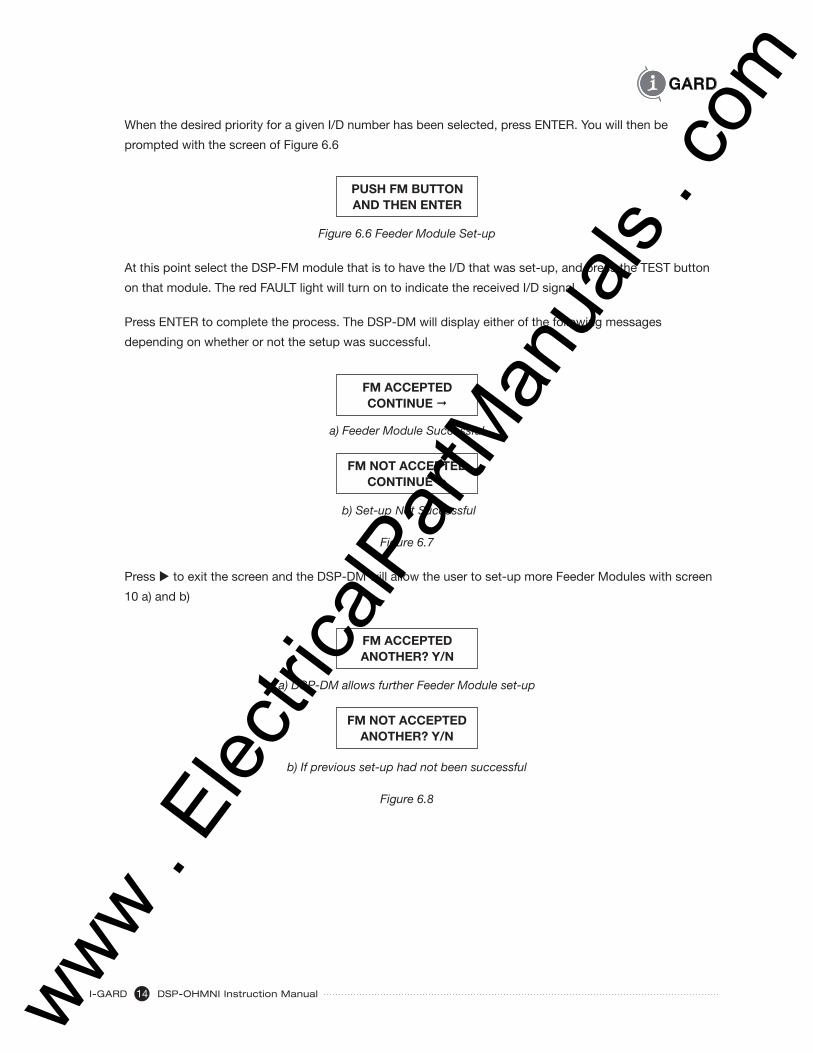
When the desired priority for a given I/D number has been selected, press ENTER. You will then be
prompted with the screen of Figure 6.6
PUSH FM BUTTONAND THEN ENTER
Figure 6.6 Feeder Module Set-up
At this point select the DSP-FM module that is to have the I/D that was set-up, and press the TEST button
on that module. The red FAULT light will turn on to indicate the received I/D signal.
Press ENTER to complete the process. The DSP-DM will display either of the following messages
depending on whether or not the setup was successful.
FM ACCEPTEDCONTINUE ®
a) Feeder Module Successful
FM NOT ACCEPTEDCONTINUE ®
b) Set-up Not Successful
Figure 6.7
Press u to exit the screen and the DSP-DM will allow the user to set-up more Feeder Modules with screen
10 a) and b)
FM ACCEPTEDANOTHER? Y/N
a) DSP-DM allows further Feeder Module set-up
FM NOT ACCEPTEDANOTHER? Y/N
b) If previous set-up had not been successful
Figure 6.8
www . El
ectric
alPar
tMan
uals
. com

DSP-OHMNI Instruction Manual I-GARD15
If more Feeder Modules need to be set-up then select Y and ENTER to repeat, or if not select N and ENTER
to exit the Feeder Module Set-up and enter the PULSE Set-up. The Pulse set-up screen allows the pulsing
mode for fault location to be changed for different frequencies and mode of operation. The screen of Figure
6.9 is shown.
6.4 PulsingSETUP PULSE? Y/N
Figure 6.9 Pulse Set-up Request
PULSE INVRT? OFF FREQ 0 LOCK? OFF
Figure 6.10 Pulse Mode Set-up
Select Y to enter the Pulse Set-up Screen which looks like Figure 6.10 which will show the existing set-up
of the PULSE module. The pulsing information is stored in the DSP-DSM, which must be installed during
setup. Press t to toggle the setting ON or OFF as required.
6.4.1 Invert / NDR MAL
The output from the DSP-DPS module is connected to a solid state relay. Normally (non Inverted operation)
the output from the ‘+’ and ‘-‘ terminals of the DSP-DPS module is zero prior to any pulsing operation,
and the relay is OFF. If Inverted mode is selected, then this voltage is 12V dc. And the relay is, therefore,
energized continuously. The choice of NORMAL or INVERTED operation depends on how the Grounding
Resistor current is connected. If the Grounding resistor consists of two series or two parallel resistors (one
main resistor and one pulse resistor) with the pulse resistor to be switched in and out by a solid state relay
then the following two options exist.
a) Pulse Up current
Pulsing upwards means to increase current from IGmax 5A to IGmax 10A, for example. In this case the
pulse resistor is normally OFF and the INVRT OFF would be selected. Pulsing would then change the
current to a higher level from 5A to 10A alternating when a 100% fault exists.
b) Pulse Down current
Pulsing downwards means to reduce the current from IGmax 5A to IGmax 2.5A, for example. In this case
the pulse resistor will be Normally ON and thus the INVRT ON mode would have to be selected. This
will mean that the solid state relay will be ON when the system is normal (no fault) and will open when
pulsing is started thus reducing current.
See Diagram 6.11 for examples of both series and parallel connected resistor arrangements.
NOTE: the INVRTed mode is the mode used with the standard OHMNI-PM resistors as supplied by I-GARD.
www . El
ectric
alPar
tMan
uals
. com

I-GARD DSP-OHMNI Instruction Manual16
Figure 6.11 Typical Examples of Pulse Circuit Connection
X0 X0 X0
X0X0
RGRG RG
RG
RP
RP RP
RP
5A
5A 2.5A 2.5A5A
5
10
0
2.5
5
0
5
0
INVRTOFF
INVRTON
INVRTON
INVRTON
INVRTOFF
5
10
02.5
5
0
a) Pulse UP ParallelResistors
b) Pulse Down ParallelResistors
c) Single Resistor
a) Pulse UP ParallelResistors
a) Pulse UP ParallelResistors
RG
+
-
+
-
+
-
+
-
+
-
www . El
ectric
alPar
tMan
uals
. com

DSP-OHMNI Instruction Manual I-GARD17
6.4.2 Pulsing Frequency
Press ENTER when the selection is chosen. The cursor will then move to the FREQuency position.
Press pq to select a pulse frequency from 0 to 9 with frequency increasing with the number selected.
It is not important to know exactly the frequency selected, however, Table 6.1. Indicates the frequency
for each setting.
TABLE 6.1 PULSING FREQUENCY SELECTION
Select 0 1 2 3 4 5 6 7 8 9
Freq Hz. 1.0 1.25 1.50 1.75 .2.00 .2.25 2.50 2.75 3.00 3.25
6.4.3 Interlock
Press ENTER after a value has been selected and the cursor moves to the interLOCK position. The
interlock prevents pulsing from occurring when there is no fault on the system. Press t to toggle ON or
OFF and then ENTER to complete the Pulse set-up.
6.5 Alarm Relay
For the next Setup the user will then be presented with the option to change the operation of the MUTE
function. The MUTE button normally disables the Alarm Relay and the local Beeper Alarm when pressed
to following a fault. However, the designer might use the Alarm Relay for some other function, for example
another contactor or cooling fan operation of the grounding resistors. In this case it is undesirable to MUTE
the relay. For this reason the operator may choose to disallow the MUTE button to change the state of
the Alarm Relay. The Screen of Figure 6.12 is presented.
ALARM RELAY Y/N
Figure 6.12 Alarm relay Setup
Selection of ‘Y’ provides the option selection screen of Figure 6.13.
MUTE ALARM RLY— ENABLED
Figure 6.13 Alarm relay Options
The default is with the Alarm Relay MUTE control Enabled to allow Silence control of an external Horn system.
Pressing — button will toggle the ENABLED to DISABLED to defeat the MUTE switch operation of the Alarm
Relay and allow it to be used for other purposes which depend on whether or not the system is in a Faulted
condition.
NOTE: This does not affect the local Beeper function which will still continue to be MUTEd by the MUTE button.
www . El
ectric
alPar
tMan
uals
. com

I-GARD DSP-OHMNI Instruction Manual18
That completes the set-up. At this point you may be presented with the option of saving the values
changed or not with the screen of Figure 6.14.
SAVE CHANGES Y/N
Figure 6.14 Save Screen
Note: You may not see this screen. If no changes were made in the set-up, or changes were made to the
Feeder Module set-up or the Pulse Set-up, it will not appear. This is because those changes are actually
saved in the DSP-DFM and DSP-DSM respectively. The changes selected will be saved in non-volatile
EEPROM memory until the next time the set-up is changed and re-saved.
Pressing ENTER after selecting Y/N.
6.6 Self Test
At this point the user is asked if SELF-TEST is desired with screen of Figure 6.15.
SELF-TEST? Y/N
Figure 6.15 Self-Test Prompt
The user can just press ENTER to ignore and return to the Home Screen, or select Y ENTER to perform
Self-Test on the system. See Self-Test section for details. See Section 9 for Self-Test.
7 OPERATION
7.1 Screen Navigation
Normally with an un-faulted system and recent RESET, the Display Module will display the Normal Home
screen of Figure 7.1 with a green NORMAL light on the front panel and no Alarm. The System Module will
indicate a green NORMAL light and the DSP-DFM modules will show no light indication at all. The DSP-DPS
supply will also indicate POWER with a green light when power is supplied to it. The yellow PULSE light may,
or may not, be ON, depending on whether, or not, the INVERTed mode of operation has been selected for
the pulse operation. If the Inverted Mode is selected the Pulse Relay will be normally energized and will de-
energize with each pulse. The PULSE light will indicate when the pulse relay is energized. In the Normal pulse
mode, the light will be OFF and will light with each pulse. The Display Module will indicate the Normal Home
screen as in Figure 7.1.
I-GARD RESISTORSHRG SYSTEM OK
Figure 7.1 Normal Home Screen
www . El
ectric
alPar
tMan
uals
. com

DSP-OHMNI Instruction Manual I-GARD19
Pressing u takes the user to the Screen 2 which shows the total system ground current IG as a percentage
of the maximum ground current allowed by the grounding Resistor. As a reference, the setting for the
Maximum Ground current is shown as IG max (5A in the example of Figure 7.2). The IGmax current must
agree with that of the Neutral Grounding Resistor of the system. If it does not then the OHMNI-PM set-up
must be repeated.
IG SYSTEM A =10%100%(IGmax) =05A
Figure 7.2 System leakage current lG
NOTE this screen can only be seen when the system does not have a fault as will be seen.
Press u again to view Screen 3 which is the Feeder Module screen in Figure 7.3 below. It allows the
user to examine the status of the installed DSP-DFM modules. Feeder Modules are identified by their I/D
numbers from 1 to 50 and may be scrolled through with the pq keys. Priority settings can be observed (10
in this case) and Ground Current Igf for the Feeder is displayed as a percentage of the maximum Ground
Current of the System. A reading of ”- -“ would represent a direct short to ground for the Feeder while 00%
represents no current leakage at all. STATus is indicated as well which shows whether or not the Feeder
Module is OK (leakage below 50%), FLT (faulted) leakage greater than 50% or TRP (Tripped) which may
happen if a second fault caused current in the sensor to exceed 100A for 200mS or more.
FDR 01 PRIOR 101Gf 07% STAT OK
Figure 7.3. Feeder Current IGf
Only those DSP-DFM modules that have valid I/D settings will indicate successfully. All others will indicate
as though they were not installed with blank characters in the display fields.
NOTE: to identify which DSP-DFM is which, if not sure, the user can push the I/D/TEST button on each DSP-DFM until the
Status indicator on the Feeder Screen shows ‘TST’. This will be the FM selected and the I/D can be read on this screen.
If the TRIP function was defeated in the Setup Mode, then the Feeder Modules that are disabled will
indicate with a screen similar to Figure 7.4
FDR 01 TRIP OFF!1Gf 07% STAT OK
Figure 7.4 Trip Defeated
www . El
ectric
alPar
tMan
uals
. com

I-GARD DSP-OHMNI Instruction Manual20
7.2 Pulsing
Press u to move to the next screen. This is the Pulsing Control Screen. It appears as in Figure 7.5.
PULSE ON/OFF —PULSING OFF “
Figure 7.5 Pulse Control
This screen is only used to turn on the Pulsing System for fault location. It will cause the OHMNI-PM
Grounding Resistor value to be modulated to permit readings to be easily detected on portable current
probes. Pulsing is toggled ON and OFF with the t button. The bottom line of the display indicates the
Status of the Pulsing Module. It should change to ON when pulsing is ON. Note: If the Pulsing cannot be
turned ON, it could be because the InterLOCK setting has been set to ON in the Pulse Set-up. In this case
Pulsing cannot be turned ON unless there is an actual fault on the system. This can be easily changed in
the Set-up configuration.
If Pulsing is selected ON, then it will remain ON until turned OFF again or RESET is pressed. The Home
screen will remind the Operator that pulsing is ON with the screen of Figure 7.6.
PULSING ONHRG SYSTEM OK
Figure 7.6 New Home screen indicates Pulsing ON
12V DC Pulse current is sent from the DSP-DPS ‘+’ and ‘-’ terminals to the DSP-PM Grounding Resistor
to energize the solid-state relay in the Resistor and by-pass part of its elements to modulate the Ground
Current (if any).
When finished with the Pulse operation press u to exit and return to the Home Screen.
8 ALARM INDICATIONS
If a fault greater than 50% of IG develops somewhere on the system, and Alarm is declared by the System
Module, this causes several events to occur.
LED indications
DSP-DM display module green NORMAL changes to red ALARM
DSP-DSM system module red ALARM light
DSP-DFM Fault Indication is enabled to provide indication if Fault is detected by Feeder
Module (Fault may not be detected by a Feeder Module - if it is on the Main Bus for
example)
www . El
ectric
alPar
tMan
uals
. com

DSP-OHMNI Instruction Manual I-GARD21
Alarms
Alarm Relay (Form C) on DSP-DPS will operate to energize customers’ alarm device
(Horn etc.)
A local beeper will sound in the DSP-DM to indicate the fault
The Alarms both local and external can be cancelled by the MUTE button, which is actually the key when
in the Alarm Screen. It will not work on the Feeder or Pulse Screens. Once cancelled the Alarm will remain
OFF until about an hour after the last button has been pressed on the keypad of the DSP-DM when it will
resume if an Alarm condition still exists. RESET will also cancel the MUTE effect.
Display
The Home screen will change to an Alarm Screen which will indicate which phase is faulted, and the branch
circuit that is affected, with a screen similar to that of Figure 8.1.
FAULT PHASE AFEEDER 01 IG 67%
Figure 8.1 Alarm Screen
The faulted Feeder is identified by I/D number. The Total System Current IG will indicate the system current
as determined by the voltage from the DDR2 resistor unit (See 8.1 above). Note this may not be exactly the
same as the Feeder Current Igf that is indicated in the Feeder Module Screen since the sum of all leakages
will not necessarily be the same as that of one particular Feeder branch.
Feeder fault information can be determined by pressing u to move to the Feeder Screen. The Faulted Feeder
(if any) can be located by scrolling with pq keys to the faulted one. The current reading Igf relating to that
feeder is shown. It should exceed 50%. The FLT status will also confirm that this is the faulted circuit. In
addition, there will be an Alarm Indication on the faulted Feeder Module which is indicated by a continuous
red LED.
In this situation it then becomes necessary to determine the source of the fault. In some cases this might
be known problem but if the fault is not quickly identified then the risk is that a second fault may develop
and cause shutdown of one of the breakers.
To locate the fault easily the Pulse system can be turned on using u to enter the Pulse Control screen.
See Fault Finding section.
www . El
ectric
alPar
tMan
uals
. com

I-GARD DSP-OHMNI Instruction Manual22
If no Feeder Faults are identified the Display Module will indicate BUS FAULT as in Figure 8.2 to indicate
this special situation. In this case the probability is that there is a fault upstream of the current sensors and
usually indicates a fault in the main transformer or bus duct which supplies the switchgear.
FAULT PHASE ABUS FAULT IG 67%
Figure 8.2 Bus Fault
This screen may also be observed under other situations as well. For example if a fault develops on a faulty
DSP-DFM or the Module is missing or a Feeder has no protection on it at all, the same indication will result.
Another situation might be on a main-tie-main system with two DSP systems and a fault develops on one
side of the gear. The DSP-DM on the other side will indicate Alarm with a BUS FAULT if the tie is closed
since it does not ‘see’ any DSP-DFM on its side with a fault.
9 SELF – TEST
Basic functionality testing of the system can be done without interrupting circuit breakers. To enter the
Test the operator must be in the Home Screen and without a fault on the system at the time. Press SETUP
button. Using the ENTER key press 4 times until the SELF-TEST screen is reached, Select Y and ENTER to
access the Self-Test. The operator is prompted with the TEST SYSTEM test as in Figure 9.1
TEST SYSTEM?Y/N
Figure 9.1 System-Test Prompt
To check the SYSTEM Module DSP-DSM, select Y and ENTER otherwise just push ENTER to move to the
Feeder Module Test.
If the SYSTEM was selected when ENTER is pressed, the Red Alarm lights on System Module and Display
Module will light and both the local and remote Alarm devices will sound. Check that the MUTE button
silences the Alarms effectively.
The prompt figure 9.2 for Feeder Module DSP-DFM automatically appears at this time. Select Y or ENTER
to perform the Feeder Module Test. Pressing ENTER will return the display to the Home Screen.
TEST FEEDER? Y/N
Figure 9.2 Prompt for Feeder Test
www . El
ectric
alPar
tMan
uals
. com

DSP-OHMNI Instruction Manual I-GARD23
The second line of the display will indicate that it is ready for a Feeder Module Test with the screen
of Figure 9.3.
TEST FEEDER? Y/NFM NO.
Figure 9.3 Feeder Module Test
At this point the operator may press any DSP-DFM TEST button and if it is good the Display will
respond with the I/D number of the selected Feeder Module and acknowledges with “OK’ as in the example
of Figure 9.4
TEST FEEDER? Y/NFM NO. 5 OK
Figure 9.4 Test Result
Press any other Feeder TEST button to check other modules similarly.
Press ENTER to leave the Self-Test and return to the Home Screen.
10 EVENTS
When a fault occurs sufficient to cause an alarm the event is recorded along with the fault current level and
location so that it can be checked on the DSP-DM display module, even if the fault has disappeared. This
can be seen on the Home screen which indicates a fault occurrence with a message as in Figure 10.1.
I-GARDFAULT CLEARED —
Figure 10.1 Event Notification
To observe what event occurred press t as indicated and hold to read the data. The display will show the
type of fault, phase faulted and the branch location if any. For example Figure 10.2 shows a typical Feeder
Fault that was momentary.
FAULT PHASE AFEEDER 03 IG 78%
Figure 10.2 Momentary Feeder Fault Example
www . El
ectric
alPar
tMan
uals
. com

I-GARD DSP-OHMNI Instruction Manual24
The following Events are supported:
Type of Event Interpretation Possible Cause
Bus Fault Fault occurred which was not a) Fault upstream in duct or identified by any Feeder Module transformer
b) Fault in unprotected Feeder branch
Phase Loss Loss of a phase on the Fuse OpenDDR2 resistor
3- Phases Lost No power on DDR2 resistor unit Power Disconnected
Feeder Fault Fault occurred on identified Momentary Ground Fault on FeederFeeder
The event will remain until superseded by another fault, which will rewrite over the previous data. The
data is volatile and will be cleared on a power interruption or operation of the RESET button.
11 MAINTENANCE AND TESTING
Due to the solid state design and the use of sealed components, it is not necessary to service the
DSP other than occasionally dusting with a damp cloth or vacuum cleaner during regular switchboard
maintenance.
To test the DSP it will normally be sufficient to use the SELF-TEST procedure (as described in
section 9).
To test the system in the field involves placing a ground fault on one of the lines. This should only be
performed with the permission of the owner and by qualified individuals using proper techniques, to ensure
safety to plant, equipment and personnel.
DANGERHazard of Electrical Shock, Burn or Explosion
All installation, servicing and testing referred to in this manual must be performed by
qualified personnel. All power should be disconnected prior to removing covers or
enclosures and where live conductors may otherwise be exposed.
Failure to observe these precautions may result in death or severe personal
injury and damage to equipment.
Before placing an intentional ground fault on the power system, check that a
fault does not already exist. Any test ground fault equipment must be rated
for full system voltage and be fused for protection.
www . El
ectric
alPar
tMan
uals
. com

DSP-OHMNI Instruction Manual I-GARD25
A complete test of the system can be accomplished with the connection of a resistive fault between one
of the three lines and ground at a location downstream of one of the Feeder current sensors. This simple
test will identify the integrity of sensor, Feeder Module circuits, connections, communications, System
Module operation, DDR2 resistor OHMNI-PM resistor and Pulsing without causing a Trip to occur on any of
the breakers. The only thing it will not test is the priority of the double-fault trip process. For this two such
resistors would be required, with resistor value low enough to provide more than the 100A trip current.
NEVER USE A PIECE OF WIRE TO CREATE A TEST FAULT. IT IS POSSIBLE THAT THE PROTECTION MAY NOT
BE OPERATIONAL DUE TO MIS-WIRING OR OTHER PROBLEMS AND CANNOT CLEAR THE FAULT CURRENT
RESULTING IN A SERIOUS ARCING SITUATION WHICH MAY SEVERELY DAMAGE THE EQUIPMENT AND CAUSE
INJURY OR DEATH.
12 SERVICE
For assistance in installation, setup or testing please call I-Gard toll free
at 1-888-737-4787 ( 1-888-RESISTR)
There are no user-serviceable parts in the DSP, therefore all service should be referred to qualified factory
representatives, other than direct replacement of entire Modules to I-Gard. Please visit the I-Gard website
for information regarding field service representatives in your area. (www.i-gard.com)
NOTE: Please ensure that proper authorisation is obtained from I-Gard before returning the equipment.
13 COMMUNICATIONS
Installation
To allow communications to a remote terminal or network, a 4-wire RS-485 communications jack is
provided at the rear of the DSP-DM Display Module. The 5-pin connector supplied has screw terminals
and allows disconnection without breaking the RS-485 daisy chain. A ground connection is supplied for
grounding the shield of the 4-wire cable. The protocol supported is MODBUS RTU. The baud rate can be
changed in the DSP-DM set-up to 4800, 9600 or 19200 as desired. The frame set-up is 8 bit, No Parity
and 1 Stop Bit. The I/D number for the DSP-DM must be entered in the set-up within the range of 1 to 32.
Cable should be standard 4-wire with two twisted-pairs ideally, and a grounding shield for emc protection.
The shield of the cable between nodes should not be continuously grounded, but each section of cable
should be grounded at GND pin of J3. When installing cable, avoid star connections and make connections
flow from node to node. Cable length of 1-2 kilometres or more should be easily accommodated.
www . El
ectric
alPar
tMan
uals
. com

I-GARD DSP-OHMNI Instruction Manual26
DSP MODBUS output structure
Two functions are supported
Read Holding Register (03)
Set Coil (05)
There are 154 registers available, which can be accessed by an external host system. This
document summarizes the format and function of these registers.
The request from the master is always 8 bytes long and are as shown in Table 13.1.
TABLE 13.1 MODBUS RTU STANDARD 8 BYTE HOLDING REGISTER READ FUNCTION (03)
Unit I/D Function Starting Address No. of Registers requested CRC
High Low High Low High Low
01 03 00 01 00 02 nn nn
All bytes are in hexadecimal. Numbers above are, for example, a request for 2 registers only,
starting from address 01. CRC checksum is 16 bit CRC as described in MODBUS information.
The high bytes are not used in any requests.
If successful the DSP will return the message shown in Table 13.2.
TABLE 13.2 RETURNED INFORMATION STRUCTURE FOR HOLDING REGISTER REQUEST
Unit I/D Function No. of bytes Data 1 Data 2 CRC
High Low High Low High Low High Low
0103 00 02 00 02 00 01 nn nn
Register contents are shown in Tables 1 to 3 as follows.
NOTE: Register number is shown in decimal but must be sent in hexadecimal form in the request.
The only write functions presently supported in the DSP system are RESET control and PULSE
ON/OFF which will require the use of Set Coil function in MODBUS. The format for Setting is as
shown in Figure 13.3
TABLE 13.3 REQUEST TO WRITE TO SET A BIT ON A REGISTER (MODBUS FORCE COIL)
Unit I/D Function Coil Address Force Coil CRC
High Low High Low High Low
01 05 00 00 ff 00 nn nn
www . El
ectric
alPar
tMan
uals
. com

DSP-OHMNI Instruction Manual I-GARD27
In this case there will only be two ‘coils’ (actually DSP functions)
‘Coil’ No Name Force Coil Data
00 Reset ff00 =on 0000=off
01 Pulse ff00 =on 0000=off
The response of Table 13.4 will confirm the request
TABLE 13.4 RETURNED INFORMATION FROM DSP FOLLOWING A FORCE BIT REQUEST
Unit I/D Function Coil Address Force Coil CRC
High Low High Low High Low
01 05 00 00 ff 00 nn nn
Which is just an echo of the request.
The registers can be read either one at a time or in a continuous block up to a maximum of 100
registers at a time.
There are times when the DSP processor will not be able to respond to a request since it is busy
with other tasks and no response will be returned. For this reason it is recommended to request
the maximum number of registers used by the system in a single request. Since the DSP is set
up to 50 current registers, 50 Status registers and 50 Priority registers followed by the System
function registers, it is best to read the data with three consecutive requests.
NOTE that the DSP will not respond to requests if the DSP-DM is in the SETUP mode.
The Feeder Module currents Igf values are contained in the first 50 registers as follows. The
values range from 0x00 to 0xff although maximum for a first fault condition will be 0x64 or 100%.
Table 13.5 lists the register addresses in the MODBUS convention.
www . El
ectric
alPar
tMan
uals
. com

I-GARD DSP-OHMNI Instruction Manual28
TABLE 13.5 FEEDER MODULE GROUND CURRENT ADDRESSES
Register No Contents Format Register No. Contents Format
40001 Feeder 1 Igf 0x00nn 40026 Feeder 26 Igf 0x00nn
40002 Feeder 2 Igf 40027 Feeder 27 Igf
40003 Feeder 3 Igf 40028 Feeder 28 Igf
40004 Feeder 4 Igf 40029 Feeder 29 Igf
40005 Feeder 5 Igf 40030 Feeder 30 Igf
40006 Feeder 6 Igf 40031 Feeder 31 Igf
40007 Feeder 7 Igf 40032 Feeder 32 Igf
40008 Feeder 8 Igf 40033 Feeder 33 Igf
40009 Feeder 9 Igf 40034 Feeder 34 Igf
40010 Feeder 10 Igf 40035 Feeder 35 Igf
40011 Feeder 11 Igf 40036 Feeder 36 Igf
40012 Feeder 12 Igf 40037 Feeder 37 Igf
40013 Feeder 13 Igf 40038 Feeder 38 Igf
40014 Feeder 14 Igf 40039 Feeder 39 Igf
40015 Feeder 15 Igf 40040 Feeder 40 Igf
40016 Feeder 16 Igf 40041 Feeder 41 Igf
40017 Feeder 17 Igf 40042 Feeder 42 Igf
40018 Feeder 18 Igf 40043 Feeder 43 Igf
40019 Feeder 19 Igf 40044 Feeder 44 Igf
40020 Feeder 20 Igf 40045 Feeder 45 Igf
40021 Feeder 21 Igf 40046 Feeder 46 Igf
40022 Feeder 22 Igf 40047 Feeder 47 Igf
40023 Feeder 23 Igf 40048 Feeder 48 Igf
40024 Feeder 24 Igf 40049 Feeder 49 Igf
40025 Feeder 25 Igf 40050 Feeder 50 Igf
Feeder Module Status is represented by fi ve valid states as follows:
0x00 = OK
0x01 = Faulted feeder
0x02 = Feeder Tripped
0x03 = Test Button pushed
0x0f = Not available
The registers following return two bytes – The fi rst byte is always 0x00 with the second returning
status in hexadecimal as above.
www . El
ectric
alPar
tMan
uals
. com

DSP-OHMNI Instruction Manual I-GARD29
TABLE 13.6 FEEDER MODULE STATUS ADDRESSES
Register No. Contents Register No. Contents
Function Format Function Format
40051 Feeder 1 Status 0x00nn 40076 Feeder 26 Status 0x00nn
40052 Feeder 2 Status 40077 Feeder 27 Status
40053 Feeder 3 Status 40078 Feeder 28 Status
40054 Feeder 4 Status 40079 Feeder 29 Status
40055 Feeder 5 Status 40080 Feeder 30 Status
40056 Feeder 6 Status 40081 Feeder 31 Status
40057 Feeder 7 Status 40082 Feeder 32 Status
40058 Feeder 8 Status 40083 Feeder 33 Status
40059 Feeder 9 Status 40084 Feeder 34 Status
40060 Feeder10 Status 40085 Feeder 35 Status
40061 Feeder 11 Status 40086 Feeder 36 Status
40062 Feeder 12 Status 40087 Feeder 37 Status
40063 Feeder 13 Status 40088 Feeder 38 Status
40064 Feeder 14 Status 40089 Feeder 39 Status
40065 Feeder 15 Status 40090 Feeder 40 Status
40066 Feeder16 Status 40091 Feeder 41 Status
40067 Feeder 17 Status 40092 Feeder 42 Status
40068 Feeder 18 Status 40093 Feeder 43 Status
40069 Feeder 19 Status 40094 Feeder 44 Status
40070 Feeder 20 Status 40095 Feeder 45 Status
40071 Feeder 21 Status 40096 Feeder 46 Status
40072 Feeder 22 Status 40097 Feeder 47 Status
40073 Feeder 23 Status 40098 Feeder 48 Status
40074 Feeder 24 Status 40099 Feeder 49 Status
40075 Feeder 25 Status 40100 Feeder 50 Status
www . El
ectric
alPar
tMan
uals
. com
I-GARD DSP-OHMNI Instruction Manual30
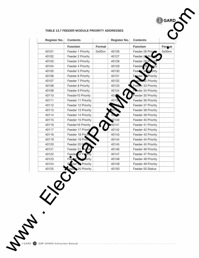
TABLE 13.7 FEEDER MODULE PRIORITY ADDRESSES
Register No. Contents Register No. Contents
Function Format Function Format
40101 Feeder 1 Priority 0x00nn 40126 Feeder 26 Priority 0x00nn
40102 Feeder 2 Priority 40127 Feeder 27 Priority
40103 Feeder 3 Priority 40128 Feeder 28 Priority
40104 Feeder 4 Priority 40129 Feeder 29 Priority
40105 Feeder 5 Priority 40130 Feeder 30 Priority
40106 Feeder 6 Priority 40131 Feeder 31 Priority
40107 Feeder 7 Priority 40132 Feeder 32 Priority
40108 Feeder 8 Priority 40133 Feeder 33 Priority
40109 Feeder 9 Priority 40134 Feeder 34 Priority
40110 Feeder10 Priority 40135 Feeder 35 Priority
40111 Feeder 11 Priority 40136 Feeder 36 Priority
40112 Feeder 12 Priority 40137 Feeder 37 Priority
40113 Feeder 13 Priority 40138 Feeder 38 Priority
40114 Feeder 14 Priority 40139 Feeder 39 Priority
40115 Feeder 15 Priority 40140 Feeder 40 Priority
40116 Feeder16 Priority 40141 Feeder 41 Priority
40117 Feeder 17 Priority 40142 Feeder 42 Priority
40118 Feeder 18 Priority 40143 Feeder 43 Priority
40119 Feeder 19 Priority 40144 Feeder 44 Priority
40120 Feeder 20 Priority 40145 Feeder 45 Priority
40121 Feeder 21 Priority 40146 Feeder 46 Priority
40122 Feeder 22 Priority 40147 Feeder 47 Priority
40123 Feeder 23 Priority 40148 Feeder 48 Priority
40124 Feeder 24 Priority 40149 Feeder 49 Priority
40125 Feeder 25 Priority 40150 Feeder 50 Status
www . El
ectric
alPar
tMan
uals
. com

DSP-OHMNI Instruction Manual I-GARD31
TABLE 13.8 SYSTEM FUNCTION REGISTERS
Register Function Format Description
40151 System IG current 0x00nn nn = 0-100% Total System
leakage current IGt
40152 System Status 0x00nn Nn
01 = Normal no fault
10 = A phase low
20 = B phase low
40 = C phase low
70 = All phases low
82 = A phase faulted
84 = B phase faulted
88 = C phase faulted
40153 Pulse setup 0x00nn nn lower byte is a composite
byte upper nibble is Mode of
operation while lower nibble
of nn is pulse frequency 0 – 9.
nn
0n = Normal, interlock OFF
1n = Inverted, interlock OFF
2n = Normal , interlock ON
3n = Inverted, interlock ON
40154 Pulse Status 0x000n n
0=Pulsing OFF
1=Pulsing ON
14 SPECIFICATIONS
14.1 Power Requirements DSP-DPS
100-240V, 50/60Hz or DC, 25VA
14.2 Maximum Ratings DSP-DPS
Control voltage 250V AC/DC
Dielectric
Relay contacts to chassis 1500V rms. for 1 minute
Control terminals to chassis 1500V rms. for 1 minute
DC output maximum rating 22W max for +5, +12 and 12V supplies
www . El
ectric
alPar
tMan
uals
. com

I-GARD DSP-OHMNI Instruction Manual32
Settings DSP-DSM System Module
Alarm Level Pickup 50% of system Ground Current IG
Trip Level Inhibit 25% of system Ground Current
14.3 Pulse Set-up
Pulse Rates
0 to 9 Setting in 0.25Hz increments
1.0,1.25,1.50,1.75, 2.0, 2.25, 2.50, 2.75, 3.0, 3.25Hz.
Pulse Modes Normal, Inverted
Pulse Interlock Normal, Interlocked with Fault Detect.
Pulse Output current 0.5A @ 12V DC
14.4 DSP-DFM
Ground Current Settings IG 1,2,3,4,5,6,7,8,9,10,11,12,13,14,15,16A
Trip Level Current 100A
Trip Level Delay 10xP +200mS (Where P=Priority setting)
Priority Levels 0 – 15 (16 settings)
14.5 Contact Ratings
DSP-DFM Trip Contacts – Form C SPDT 10 amperes, 240V AC resistive
DSP-DPS Alarm Contacts – Form C SPDT 8 amperes, 240V AC resistive
14.6 Performance
DSP-DFM
Pickup accuracy ±10% of system let-through current
Trip Level accuracy ±10A
DSP-DSM
Alarm Level Accuracy ±10% of IG
Meter accuracy ±10% of IG
NOTE: Accuracy based on single resistance fault, at nominal line voltage, without system capacitance.
Temperature Range: Operating temperature 0°C-+50°C
Standards CSA File number LR65287
UL E232710
www . El
ectric
alPar
tMan
uals
. com

DSP-OHMNI Instruction Manual I-GARD33
Physical Weight 1.5kg
Dimension See Fig. 17(next)
I-Gard reserves the right to change specifications of its products without notice.
15 OUTLINE DIMENSIONS
Figure 15.1 shows typical Dimensional details of the Polymeric enclosures used for the modules.
All have the same cross-section dimensions but with different widths W as shown.
58.00mm
W
Figure 15.1 DIN Rail Mounted Modules
Module W
DSP-DFM 35mm (1.377 in.)
DSP-DSM 70mm (2.755 in.)
DSP-DPS 155mm (6.102 in.)
DSP-CAS 70mm (2.755in.)
DSP-CA 70mm (2.755in.)
www . El
ectric
alPar
tMan
uals
. com

I-GARD DSP-OHMNI Instruction Manual34
4.25 (108mm)
6.50 (165mm)
Drill two holes ANo 36 TAP or
No 23 Clearance6-32 ScrewA A
Figure 15.2 DSP-DM Display Module with cut-out detail
www . El
ectric
alPar
tMan
uals
. com

DSP-OHMNI Instruction Manual I-GARD35
-
20 conductorRibbon ToDSP-DPS
20 conductorRibbon ToDSP-DFM
ABCNGND
Figure 15.4 DSP-DSM System Module Connection
Figure 15.3 DSP-DPS Power Supply Connections
NC NOCOM + - AC IN GND GND
20 conductorRibbon ToDSP-DM
20 conductorRibbon ToDSP-DSM
-
20 conductorRibbon ToDSP-DSM
20 conductorRibbon To Other
DSP-DFM
COMNCNOSGND
1000:1Zero-SequenceCurrent Sensor
Figure 15.5 DSP-DFM Feeder Module Connection
www . El
ectric
alPar
tMan
uals
. com

I-GARD DSP-OHMNI Instruction Manual36
J3 RS-485Communications
20 ConductorCable to DSP-DPS
To Next Device, orConverter
J1
Figure 15.6 DSP-DM Display Module Connections
16 ADDITIONAL INFORMATION
If you require more information or experience problems with your equipment that persist after taking the steps
identified in this manual, please contact I-Gard Customer Service.
www . El
ectric
alPar
tMan
uals
. com

17 INSTRUCTION MANUALS
C-407 GCHK-100 Mining RelayGround Fault ProtectionSystem Manual
C-408 SleuthHigh Resistance Grounding System Manual
C-322 MGFRGround Fault Relay Manual
C-409 DSP OHMNIHigh ResistanceGrounding System Manual
C-102 GeminiHigh Resistance GroundingSystem Manual
C-101 StoplightHigh Resistance GroundingSystem Manual
C-105 FusionGround Fault ProtectionSystem Manual
C-403 GFR-RM SIGMAResistor Monitoringand Ground Fault Relay
C-107 SENTINELHigh ResistanceGrounding System
www . El
ectric
alPar
tMan
uals
. com

7615 Kimbel St., Unit 1
Mississauga, Ontario
Canada L5S 1A8
Phone 905-673-1553
Toll Free 1-800-737-4787
Fax 905-673-8472
e-mail: [email protected]
www.i-gard.comthe
pow
er to
pro
tect
www . El
ectric
alPar
tMan
uals
. com