duane arnold - six-month status report and phase 1 and 2 ...duane arnold energy center docket no....
TRANSCRIPT
ENEx~r'YENDUANE
December 22, 2015
U. S. Nuclear Regulatory CommissionATTN: Document Control DeskWashington, DC 20555-0001
NG-15-0361
Duane Arnold Energy CenterDocket No. 50-331Renewed Facility Operating License No. DPR-49
NextEra Energy Duane Arnold, LLC's Six-Month Status Report and Phase 1 and 2 OverallIntegrated Plan in Response to June 6, 2013 Commission Order Modifying Licenses withRegqard to Reliable Hardened Containment Vents Capable of Operation Under SevereAccident Conditions (Order Number EA-1 3-109)
References: 1. .order EA-1 3-109, Order Modifying Licenses with Regard to ReliableHardened Containment Vents Capable of Operation Under SevereAccident Conditions, dated June 6, 2013 (ML13130A067)
2. NEF 13-02, "Industry Guidance for Compliance with Order EA-1 3-1 09BWR Mark I & II Reliable Hardened Containment Vents Capable of.Operation Under Severe Accident Conditions," Revision 1, dated April2015 (ML15113B318)
3. JLD-ISG-2015-01, Compliance with Phase 2 of Order EA-13-1 09, OrderModifying Licenses with Regard to Reliable Hardened Containment VentsCapable of Operation Under Severe Accident Conditions, Revision 1,d~ated April 2015 (ML15104A118)
4. NextEra Energyv Duane Arnold, LLC's Phase I Overall Inteqrated Plan inResponse to June 6, 2013 Commission Order Modifying Licenses withRegard to Reliable Hardened Containment Vents Capable of OperationUnder Severe Accident Conditions (Order Number EA-1 3-1 09), NG-14-0151 dated June 25, 2014 (ML14182A423)
5. NextEra Energy Duane Arnold, LLC's Six-Month Status Report inResponse to June 6, 2013 Commission Order Modifying Licenses with.Regard to Reliable Hardened Containment Vents Capable of OperationUnder Severe Accident Conditions (Order Number EA-1 3-1 09), NG-14-0285 dated December 10, 2014
6. NextEra Energy Duane Arnold, LLC's Six-Month Status Report inResponse to June 6, 2013 Commission Order Modifying Licenses withRegard to Reliable Hardened Containment Vents Capable of OperationUnder Severe Accident Conditions (Order Number EA-1 3-1 09), NG-15-0169 dated June 18, 2015
7. NEI document, Hardened Containment Venting System (HCVS) Phase Iand 2 Overall Integrated Plan Template (ML15272A336)
8. NRC letter dated October 8, 2015 regardingq NEI document, HCVS Phase1 and 2 Overall Integrated Plan Template (ML15271A148)
NextEra Energy Duane Arnold, LLC, 3277 DAEC Road, Palo, IA 52324
Document Control DeskNG-1 5-0361Page 2 of 3
On June 6, 2013, the Nuclear Regulatory Commission ("NRC" or "Commission") issuedOrder EA-1 3-109 (Reference 1) to NextEra Energy Duane Arnold, LLC. The Order wasimmediately effective and directed the Duane Arnold Energy Center (DAEC) to install areliable hardened venting capability for pre-core damage and under severe accidentconditions, including those involving a breach of the reactor vessel by molten core debris.Specific requirements are outlined in Attachment 2 of Reference 1.
Section IV, Condition D. 1 of the Order required submission of an overall integrated plan(DIP) including a description of how compliance with Phase 1 requirements would beachieved. Section IV, Condition D.3 required submission of status reports at six-monthintervals thereafter. Section IV, Condition D.2 required submission of an overall integratedplan including information regarding Phase 2 requirements, compliance and schedule.
The enclosed plan document satisfies the requirements of Section IV, Conditions D.2 andD.3. The enclosed plan document incorporates the third six-month update for Phase 1 ofthe Order into the HCVS Phase 1 and Phase 2 overall integrated plan document, inaccordance with NEI 13-02, Industry Guidance for Compliance with Order EA-1 3-1 09,Revision 1 (Reference 2). NEI 13-02 Revision 1 was endorsed, with exceptions andclarifications, by the NRC Staff in Reference 3. The enclosed plan document provides anupdate of milestone accomplishments since the second six-month status update, a list ofthe Phase I10IP open items, and addresses the NRC Interim Staff Evaluation open itemsfor Phase 1.
The enclosed plan document provides a complete updated Phase 10DIP. The Phase 1DIP for DAEC was submitted by letter dated June 25, 2014 (Reference 4); the first andsecond six-month updates were provided by References 5 and 6, respectively. Asdiscussed in Reference 6, the planned HCVS design was changed subsequent to thesubmittal of the Phase 10DIP in June of 2014. The HCVS design will use an existingspare penetration off of the suppression pool and route vent piping through the reactorbuilding (RB) and out of the RB roof, rather than the design reported in the June 2014DIP. This change necessitated revisions in several sections of the Phase 10DIP whichare reflected in the enclosed plan document. Additional design details have beenmodified in the enclosed document plan as required. The enclosed document planrepresents the combined Phase 1 and Phase 2 Overall Integrated Plan (combinedDIP).. The combined DIP provides our Phase 2 implementation plan includinginformation regarding Phase 2 requirements, compliance and schedule. The enclosedcombined DIP was developed using the NE! template (Reference 7) as endorsed by
-the NRC Staff in Reference 8.
Future six-month status reports will provide the updates for both Phase 1 and Phase 20OIP*implementation in a single status report, in accordance with NEI 13-02, Revision 1.
This letter contains no new regulatory commitments. If you have any questions regardingthis submittal, please contact Curt Bock at 319-851-7645.

Document Control DeskNG-1 5-036 1Page 3 of 3
I declare under penalty of perjury that the foregoing is true and correct.Executed on December 22, 2015.
( T. A. VehecVice President, Duane Arnold Energy CenterNextEra Energy Duane Arnold, LLC
Enclosure
cc: Director, Office of Nuclear Reactor RegulationUSNRC Regional Administrator Region IllUSNRC Project Manager, Duane Arnold Energy CenterUSNRC Resident Inspector, Duane Arnold Energy Center
Enclosure to NG-15-0361
NextEra Enerqy Duane Arnold, LLC's Six-Month Status Report and Phase I and 2Overall Integrated Plan in Response to June 6, 2013 Commission Order Modifying
Licenses With Regard to Reliable Hardened Containment Vents Capable of OperationUnder Severe Accident Conditions (Order Number EA-1 3-109)
63 pages follow
Duane Arnold Energy Center Hardened Containment Venting System (HCVS)Phase 1 and 2 Overall Integrated Plan
Table of Contents:
Part 1: General Inteqrated Plan Elements and Assumptions
Part 2: Boundary_ Conditions for Wet Well Vent
Part 3: Boundary Conditions for EA-1 3-1 09, Option B.2
Part 3.1 Boundary Conditions for SAWA
Part 3.IA Boundary Conditions for SAWAISAWM
Part 3.IB Boundary Conditions for SAWA/SADV
Part 4: Programmatic Controls, Training. Drills and Maintenance
Part 5: Implementation Schedule Milestones
Attachment 1: HCVS/SAWA Portable Equipment
Attachment 2A: Sequence of Events HCVS
Attachment 2.1 .A: Sequence of Events Timeline - SAWA / SAWMAttachment 2.1 .B: Sequence of Events Timeline - SADV
Attachment 2.1 .C: SAWA / SAWM Plant-Specific Datum
Attachment 2.1 .0: SAWM SAMG Approved Lanquaqe
Attachment 3: Conceptual Sketches
Attachment 4: Failure Evaluation Table
Attachment 5: References
Attachment 6: Chanqes/Updates to this Overall Inte~qrated Implementation Plan
Attachment 7: List of Overall Inte~qrated Plan Open Items
OIP Phase 1 and Phase 2 Rev. 0Oae1o 3 eebr21Page 2 of 63 December 2015
Duane Arnold Energy Center Hardened Containment Venting System (HCVS)Phase I and 2 Overall Integrated Plan
Introduction
In 1989, the NRC issued Generic Letter 89-16, "Installation of a Hardened Wetwell Vent," to all licenseesof BWRs with Mark I containments to encourage licensees to voluntarily install a hardened wetwell vent.In response, licensees installed a hardened vent pipe from the suppression pool to some point outside thesecondary containment envelope (usually outside the reactor building). Some licensees also installed ahardened vent branch line from the drywell.
On March 19, 2013, the Nuclear Regulatory Commission (NRC) Commissioners directed the staff perStaff Requirements Memorandum (SRM) for SECY -12-0157 to require licensees with Mark I and Mark<II containments to "upgrade or replace the reliable hardened vents required by Order EA-12-050 with acontainment venting system designed and installed to remain functional during severe accidentconditions." In response, the NRC issued Order EA-13-109, Issuance of Order tO ModifyingLicenses with Regard to Reliable Hardened Containment Vents Capable of Operation Under SevereAccidents, June 6, 2013. The Order (EA-13-109) requires that licensees of BWR facilities with Mark Iand Mark II containment designs ensure that these facilities have a reliable hardened vent to removedecay heat from the containment, and maintain control of containment pressure within acceptable limitsfollowing events that result in the loss of active containment heat removal capability while maintainingthe capability to operate under severe accident (SA) conditions resulting from an Extended Loss of ACPower (ELAP).
The Order requirements are applied in a phased approach where:
"Phase 1 involves upgrading the venting capabilities from the containment wetwell to providereliable, severe accident capable hardened vents to assist in preventing core damage and, ifnecessary, to provide venting capability during severe accident conditions." (Completed "no laterthan startup from the second refueling outage that begins after June 30, 2014, or June 30, 2018,whichever comes first.")
*"Phase 2 involves providing additional protections for severe accident conditions thr'oughinstallation of a reliable, severe accident capable drywell vent system or the development of areliable containment venting strategy that makes it unlikely that a licensee would need to ventfrom the containment drywell during severe accident conditions." (Completed "no later thanstartup from the first refueling outage that begins after June 30, 2017, or June 30, 2019,whichever comes first.")
The NRC provided an acceptable approach for complying with Order EA- 13-109 through Interim StaffGuidance (JLD-ISG-2013-02 issued in November 2013 and JLD-ISG-2015-01 issued in April 2015). TheISG endorses the compliance approach presented in NEI 13-02 Revision 0 and 1, Compliance with OrderEA-13-109, Severe Accident Reliable Hardened Containment Vents, with clarifications. Except in thosecases in which a licensee proposes an acceptable alternative method for complying with Order EA- 13-109, the NRC staff will use the methods described in the ISGs to evaluate licensee compliance aspresented in submittals required in Order EA- 13-1 09.
The Order also requires submittal of an overall integrated plan which will provide a description of howthe requirements of the Order will he achieved. This document provides the Overall Integrated Plan (OIP)for complying with Order EA- 13-109 using the methods described in NEI 13-02 and endorsed by NRCJLD-ISG-2013-02 and JLD-ISG-2015-01. Six month progress reports will be provided consistent with therequirements of Order EA 13-109.
The submittals required are:
OIP Phase 1land Phase 2 Rev. 0 Pg f6 eebr21Page 2 of 63 December 2015
Duane Arnoid Energy Center Hardened Containment Venting System (HCVS)Phase 1 and 2 Overall Integrated Plan
[] OIP for Phase 1 of EA-1 3-109 was required to be submitted by Licensees to the NRC by June30, 2014. The NRC requires periodic (6 month) updates for the HCVS actions being taken.The first update for Phase 1, was due December 2014, with the second due June 2015.
[] OIP for Phase 2 of EA-13-109 is required to be submitted by Licensees to the NRC byDecember 31, 2015. It is expected the December 2015 six month update for Phase 1 will becombined with the Phase 20OIP submittal by means of a combined Phase 1 and 20OIP.
[] Thereafter, the 6 month updates will be for both the Phase 1 and Phase 2 actions untilcomplete, consistent with the requirements of Order EA- 13-109.
Note: At the Licensee's option, the December 2015 six month update for Phase 1 may beindependent of the Phase 20IP? submittal, but will require separate six month updates for Phase 1and 2 until each phase is in compliance.
The Plant venting actions for the EA- 13-109, Phase 1 severe accident capable venting scenariocan be summarized by the following:
*The HCVS will be initiated via manual action from the either the Main Control Room (MCR)(some plants have a designated Primary Operating Station (POS) that will be treated as the mainoperating location for this order) or from a Remote Operating Station (ROS) at the appropriatetime based on procedural guidance in response to plant conditions from observed or derivedsymptoms.
*The vent will utilize Containment Parameters of Pressure and Level fromn the MCRinstrumentation to monitor effectiveness of the venting actions.
*The vent operation will be monitored by HCVS valve position, temperature, and effluentradiation levels.
* The HCVS motive force will be monitored and have the capacity to operate for 24 hours withinstalled equipment. Replenishment of the motive force will be by use of portable equipmentonce the installed motive force is exhausted.
* Venting actions will be capable of b~eing maintained for a sustained period of up to 7 days or a
shorter tine if justified.
The Phase 2 actions can be summarized as follows:
*Utilization of Severe Accident Water Addition (SAWA) to initially inject water into the ReactorPressure Vessel (RPV) or Drywell.
*Utilization of Severe Accident Water Management (SAWM) to control injection and SuppressionPool level to ensure the HCVS (Phase 1) wetwell vent (SAWVJ) will remain functional for theremoval of decay heat from containment.
*Ensure that the decay heat can be removed from the containment for seven (7) days using theHCVS or describe the alternate method(s) to remove decay heat from the containment from thetime the HCVS is no longer functional until alternate means of decay heat removal areestablished that make it unlikely the drywelI vent will be required for DW pressure control.
*The SAWA and SAWM actions will be manually activated and controlled from areas that areaccessible during severe accident conditions.
*Parameters measured should be Drywell pressure, Suppression Pool level, SAWA flowrate andthe HCVS parameters listed above.
OiP Phase 1 and Phase 2 Rev. 0 Pg f6 eebr21Page 3 of: 63 December 20:1,5

Duane Arnold Energy Center Hardened Containment Venting System (HCVS)Phase 1 and 2 Overall Integrated Plan
* Alternatively SAWA and a Severe Accident Capable Drywell Vent (SADV) strategy may beimplemented to meet Phase 2 of Order EA- 13-109.
Part 1: General Integrated Plan Elements and Assumptions
•!E!xtent to :which: the guidance, JLD-ISG-2013,02, ,JL D-ISG-2015,-01 and.NEIT 13-02 (evision 1:), arelbeingfollowed:. Identif any dewiations..-' .,, '' :, " , ': •":' :,,:.:,, . . ', : ..: ,,::~ ,,.i•.;,;
Include a description of any alternatives to the guidance. A technical }ustification and basis for the alternative needs to beprovided. This will likely require a pre-meeting with the NRC to review the alternative.
Ref: J-LD-ISG-2013-02, J-LD-ISG-2015-01
Compliance will be attained for Duane Arnold Energy Center (DAEC) with no known deviations to the guidelines in JLD-ISG-2013-02, JLD-JSG-2015-01 and NEI 13-02 for each phase as follows:
The Hardened Containment Vent System (HCVS) will be comprised of installed and portable equipment andoperating guidance:
* Severe Accident Wetwell Vent (SAWV) - Permanently installed vent from the Suppression Pool to thetop of the Reactor Building (RB).
* Severe Accident Water Addition (SAWA) - A combination of permanently installed and portableequipment to provide a means to add water to the RPV following a severe accident and monitor systemand plant conditions.
* Severe Accident Water Management (SAWM\) strategies and guidance for controlling the water additionto the RPV for the sustained operating period. (reference attachment 2.1 .D)
* Phase 1 (wetwell): by the startup from the second refueling outage that begins after June 30, 2014, or June 30,2018, whichever comes first. Currently scheduled for 4th~ quarter 2016.
* Phase 2 (alternate strategy): by the startup from the first refueling outage that begins after June 30, 2017 or June30, 2019, whichever comes first. Currently scheduled for 4th quarter 2018.
If deviations are identified at a later date, then the deviations will be communicated in a future 6 month update followingidentification.
Stiate;Applicable Extremne External Hazard, from NEi ,12-06,: section 4.0-9.•0',•:.•!::,'•ii,~li:•!li•~):i
List resultant determination of screened in hazards from the EA-12-049 Compliance.
Ref: NET 13-02 Section 5.2.3 and D.1.2
The following extreme external hazards screen-in for DAEC
* Seismic, Extemnal Flooding, Extreme Cold, High Wind, Extreme Hiugh Temperature
The following extreme external hazards screen out for DAEC
* None
•Ke~yNiSte: assumptions to= imnplement NEl. 13-02 HCVS, .Phase I1 and.2 Acbions: :.... .> :,.> .,•, .,
OIP Phase 1 and Phase 2 Rev. 0 Pg f6 eebr21Page 4 of 63 December 2015
Duane Arnold Energy Center Hardened Containment Venting System (HCVS)Phase 1 and 2 Overall Integrated Plan
Part 1: General Inte~qrated Plan Elements and Assumptions
Provide key assumptions associated with implementation of HGCVS Phase 1 and Phase 2 Actions
Ref: NEI 13-02, Revision 1, Section 2 NIEL 12-06 Revision 0
Mark I/Il Generic EA-13-1 09 Phase 1 and Phase 2 Related Assumptions:
Applicable EA-12-049 assumptions:
049-1. Assumed initial plant conditions are as identified in NEl 12-06 section 3.2.1.2 items 1 and 2.
049-2. Assumed initial conditions are as identified in NEl 12-06 section 3.2.1.3 items 1, 2, 4, 5, 6 and 8.
049-3. Assumed reactor transient boundary conditions are as identified in NEI 12-06 section 3.2.1.4 items 1, 2, 3 and 4.
049-4. No additional events or failures are assumed to occur immediately prior to or during the event, including securityevents except for failure of RCIC or HPCI. (Reference NEI 12-06 3.2.1.3 item 9)
049-5. At Time=0 the event is initiated and all rods insert and no other event beyond a common site ELAP is occurring atany or all of the units. (NEI 12-06, section 3.2.1.3 item 9 and 3.2.1.4 item 1-4)
049-6. At approximately one hour, an ELAP is declared and actions begin as defined in EA-12-049 compliance.
049-7. DC power and distribution can be credited for the duration determined per the EA- 12-049 (FLEX) methodologyfor battery usage. This assumption applies to the water addition capability under SAWA/SAWM. The powersupply scheme for the HCVS shall be in accordance with EA-13-109 and the applicable guidance. (NEI 12-06,section 3.2.1.3 item 8)
049-8. Deployment resources are assumed to begin arriving at hour 6 and fully staffed by 24 hours.
049-9. All activities associated with plant specific EA- 12-049 FLEX strategies that are not specific to implementation ofthe HCVS, including such items as debris removal, communication, notification, SFP level and makeup, securityresponse, opening doors for cooling, and initiating conditions for the event, can be credited as previouslyevaluated for FLEX. (Refer to assumption 109-02 below for clarity on SAWA)(HCVS-FAQ- 11)
Applicable EA- 13-109 generic assumptions:
109-0 1. Site response activities associated with EA-13-109 actions are considered to have no access limitations associatedwith radiological impacts while RPV level is above 2/3 core height (core damage is not expected). This is furtheraddressed in HCVS-FAQ- 12.
109-02. Portable equipment can supplement the installed equipment after 24 hours provided the portable equipmentcredited meets the criteria applicable to the HCVS. An example is use of FLEX portable air supply equipment thatis credited to recharge air lines for HCVS components after 24 hours. The FLEX portable air supply used must bedemonstrated to meet the "SA Capable" criteria (Severe Accident) that are defined in NEI 13-02 Section 4.2.4.2and Appendix D Section D. 1.3. This assumption does not apply to Phase 2 SAWA/SAWM because SAWAequipment needs to be connected and placed in service within 8 hours fromn the time of the loss of RPV injection.(reference HCV S -FAQ - 12)
109-03. SFP level is maintained with either on-site or off-site resources such that the SEP does not contribute to theanalyzed source term (Reference HCVS-FAQ-07).
109-04. Existing containment components design and testing values are governed by existing plant primamy containmentcriteria (e.g., Appendix J) and are not subject to the testing criteria from N7EI 13-02 (reference HCVS-FAQ-05 andNEI 13-02 section 6.2.2).
109-05. Classical design basis evaluations and assumptions are not required when assessing the operation of the IC VS.The reason this is not required is that the order postulates an unsuccessful mitigation of an event such that an ELAP
OIP Phase 1land Phase 2 Rev. 0 Pg f6 eebr21Page 5 of 63 December 2015
Duane Arnold Energy Center Hardened Containment Venting System (HCVS)Phase 1 and 2 Overall Integrated Plan
Part 1: General Inteqirated Plan Elements and Assumptions
progresses to a severe accident with ex-vessel core debris which classical design basis evaluations are intended toprevent. (Reference NEI 13-02 section 2.3.1).
109-06. HCVS manual actions that require minimal operator steps and can be performed in the postulated thermal andradiological environment at the location of the step(s) (e.g., load stripping, control switch manipulation, valving-innitrogen bottles) are acceptable to obtain HCVS venting dedicated functionality. (reference HCVS-FAQ-0 1) Thisassumption does not apply to Phase 2 SAWA/SAWM because SAWA equipment needs to be connected and placedin service within 8 hours from the time of the loss of RIPV injection and will require more than minimal operatoraction.
109-07. HCVS dedicated equipment is defined as vent process elements that are required for the HtCVS to function in anELAP event that progresses to core melt ex-vessel. (reference HCVS-FAQ-02 and White Paper HCVS-WP-0 1).This assumption does not apply to Phase 2 SAWA/SAWM because SAWA equipment is not dedicated to HCVSbut shared to support FLEX functions. This is further addressed in HCVS-FAQ-1 1.
109-08. Use of MAAP Version 4 or higher provides adequate assurance of the plant conditions (e.g., RPV water level,temperatures, etc.) assumed for Order EA-13-109 BDBEE and SA HCVS operation. (reference FLEX MAAPEndorsement ML 13 190A201) Additional analysis using RELAP 5/MOD 3, GOTHIC, P CFLUD, LOCADO SE andSHIELD are acceptable methods for evaluating environmental conditions in areas of the plant provided the specificversion utilized is documented in the analysis. MAAP Version 5 was used to develop EPRI Technical Report3002003301 to support drywell temperature response to SAWA under severe accident conditions.
109-09. NRC Published Accident evaluations (e.g. SOARCA, SECY-12-0 157, and NUREG 1465) as related to Order EA-13-109 conditions are acceptable as references. (Reference NEJ 13-02 section 8).
109-10. Permanent modifications installed or planned per EA-12-049 are assumed implemented and may be credited foruse in EA-13-109 Order response.
109-11. This Overall Integrated Plan is based on Emergency Operating Procedure changes consistent with EPG/SAGsRevision 3 as incorporated per the sites EOP/SAMG procedure change process. This assumption does not apply toPhase 2 SAWM because SAWM requires changes to the EPG/SAGs per approved issue fr'om the BWROGEmergency Procedures Committee.
109-12. Under the postulated scenarios of Order EA-13-109 the Control Room is adequately protected from excessiveradiation dose due to its distance and shielding from the reactor (per General Design Criterion (GD C) 19 in10OCFR5O Appendix A) and no further evaluation of its use as the preferred HCVS control location is requiredprovided that the HCVS routing is a sufficient distance away from the MCR or is shielded to minimize impact tothe MCR dose. In addition, adequate protective clothing and respiratory protection are available if required toaddress contamination issues. (reference HCVS-FAQ-0 1 and HCVS-FAQ-09)
109-13. The suppression pool/wetwell of a BWR Mark 1111 containment is considered to be bounded by assuming asaturated environment for the duration of the event response because of the water/steam interactions.
109-14. RPV depressurization is directed by the EPGs in all cases prior to entry into the SAGs. (reference NEI 13-02 Rev1, section 1.1.3)
109-15 The Severe Accident impacts are assumed on one unit only due to the site compliance with NRC Order EA-12-049.However, each BWIR Mk I and II under the assumptions of NRC Order EA-13-l109 ensure the capability to protectcontaimnent exists for each unit. (HC VS-FAQ- 10)
Plant Specific HCVS Related Assumptions/Characteristics:
PLT- 1. The rupture disk will be manually breeched if desired for anticipatomy/venting to allow establishing a containmentOI hs n Pae2Rv Pag f6 Decmbr 01
Page 6 of 63 December 2015

Duane Arnold Energy Center Hardened Containment Venting System (HCVS)Phase I and 2 Overall Integrated Plan
Part 1: General Integrated Plan Elements and Assumptionsvent path when containment pressure is approximately 10 psig (approximately 3.3 hours).
PLT-2. The existing torus hard pipe vent system (discharging to the offgas stack) will be decommissioned. A new HCVSwill be installed off of existing (capped) 12" torus nozzle N23 0A. The new vent will be routed from the TorusRoom to the Southwest Corner Room, up through Reactor Building (RB) South Stairwell #6 to the RB RefuelFloor, and vent to atmosphere through the roof of the RB. The piping from the 12" torus nozzle will be reduced to10" and remain at 10" for the entire vent length. The HCVS will include two Containment Isolation Valves (CV-4360 and CV-4361) and a rupture disc (PSE-43 62).
Part 2: Boundary Conditions for Wet Well Vent• "provid'e a• seque~nce of.-eve nts and •identify aniy time; or enviro bn mental• constrait- hteumd!for!,,
HCVS Actions that have a time constraint to be successful should be identified with a technical basis and a justificationprovided that the time can reasonably be met (for example, action to open vent valves).
HCVS Actions that have an environmental constraint (e.g. actions in areas of High Thermal stress or High Dose areas)should be evaluated per guidance.
Describe in detail in this section the technical basis for the constraints identified on the sequence of events timelineattachment.
See attached sequence of events timeline (Attachment 2A)
Ref: EA-13-109 Section 1.1.1, 1.1.2, 1.1.3 / NEI 13-02 Section 4.2.5, 4.2.6. 6.1.1
OIP Phase 1 and Phase 2 Rev. 0 Pg f6 eebr21Page 7 of 63

Duane Parnol Enrg Ceuntedardee Condtainmnt Voentin Syseml (HV S)t
Part 2: Boundary Conditions for Wet Well Vent
The operation of the HCVS will be designed to minimize the reliance on operator actions in response to hazards listed inPart 1. Initial operator actions will be completed by plant personnel and will include the capability for remote-manualinitiation from the HCVS control station. A list of the remote manual actions performed by plant personnel to open theHCVS vent path can be found in the following table (2-1). A HCVS Extended Loss of AC Power (ELAP) FailureEvaluation table, which shows alternate actions that can be performed, is included in Attachment 4.
Table 2-1 HCVS Remote Manual ActionsPrimary Action Primary Location / Notes
Component
1. Breach the rupture disk (PSE- MCR I Nitrogen supply valve Not required during SA4362) by pressurizing the piping key lock hand switch at Panel eventbetween control valve CV-4361 1014. Ol eurdiand rupture disc PSE-4362. prOrmngy reaurlyi
venting for FLEX
2. Open HCVS PCIVs CV-4360 MCR I key lock hand switch
and CV-4361 located in MCR at 1014
3. Confirm Vent is open. MCR I PCIV Position Indication,Temperature Indication andRadiation Monitor in MCR
4. Replenish pneumatics with Nitrogen bottles can be placed Prior to depletion of thereplaceable nitrogen bottles inan area that is accessible to pneumatic sources
operators (ROS) actions will be requiredto connect replacementNitrogen bottles at atime greater than 24hours.
5. Re-align power supplies for allvalves and instruments toportable sources or restorenormal power supplies.
Control Building 1A3Switchgear Room
Prior to depletion of theinstalled powersources actions will berequired to connectback-up sources at atime greater than 24hours.
Provide a ~ and identify any time or environmental~onstraint for successincluding4he~qutmceo1evvuI.~ required,basis for the coj straint. I
A timeline was developed to identify required operator response times and potential environmental constraints. Thistimeline is based upon the following three cases:
1. Case 1 is based upon the action response times developed for FLEX when utilizing anticipatomy venting in aBDBEE without core damage.
2. Case 2 is based on a SECY-12-0 157 long term station blackout (LTSBO) (or ELAP) with failure of RCICafter a black start where failure occurs because of subjectively assuming over injection.
3. Case 3 is based on NUJREG-1935 (SOARCA) results for a prolonged SBO (or ELAP) with the loss of ROICcase without black start.
OIP Phase 1land Phase 2 Rev. 0Oae8o 3 eebr21Page 8 of 63 December 2015

Duane Arnold Energy Center Hardened Containment Venting System (HCVS)Phase 1 and 2 Overall Integrated Plan
Part 2: Boundary Conditions for Wet Well Vent
The following is a discussion of time constraints identified in Attachment 2A for the 3 timeline cases identified above
•At approximately 3.3 hours, initiate use of Hardened Containment Vent System (HCVS) per site procedures tomaintain containment parameters below design limits and within the limits that allow continued use of RCIC. Thereliable operation of HCVS will be met because HCVS meets the seismic requirements identified in NE1 13-02and will be powered by the HCVS uninterruptible power supply, with motive force supplied to HCVS valves fr'oman installed bank of nitrogen storage bottles. Critical HCVS controls and instruments associated with contaimnentwill be DC powered and operated from the MCR or a Remote Operating Station. The DC power for HCVS will beavailable as long as the UCVS is required. 1-CVS uninterruptable power supply battery capacity will be availableto extend past 24 hours. In addition, when available the Phase 2 FLEX Diesel Generator (DO) can provide powerbefore battery life is exhausted. Thus, initiation of the HCVS from the MCR or the Remote Operating Stationwithin approximately 3.3 hours is acceptable because the actions can be perfonned any time after declaration of anELAP and prior to reaching containment pressure limits. For purposes of analysis, a containment pressure of 10PSIG was selected for initiation of venting and initiation after 10 PSIG but prior to reaching containmentpressures of 53 PSIG (greater than 7 hours) is also acceptable for BDBEE venting. This action can also beperformed for SA HCVS operation which occur at a time further removed firom an ELAP declaration as shown inAttachment 2A.
* At appi'oximately 24 hours, portable nitrogen bottles will be valved-in at the ROS to supplement the Nitrogenbank supply, if needed. This can be performed at any time prior to 24 hours to ensure adequate capacity ismaintained so this time constraint is not limiting.
* Under the FLEX program, one of two portable diesel generators can be connected to station 480 Volt electricaldistribution at MCC 1B32. From this motor control center, electrical power can be supplied to the planneduninterruptable power supply (UPS) for HCVS prior to depletion of the UPS batteries. For purposes ofcompliance with order EA-13-109 no credit is taken for this action until after 24 hours. Thus, the DG will beavailable to be placed in service at any point after 24 hours as required to supply power to HCVS criticalcomponents/instruments. A DO will be maintained in on-site FLEX storage buildings. The DG will betransferred and staged via haul routes and staging areas evaluated for impact firom external hazards. Connectionpoints will be installed to facilitate the connections and operational actions required to supply power for days 2-7of the ELAP. For Phase 2 applicability, the 8-10 hours will change to 6-8 hours and will be validated by thePhase 2 Verification and Validation thus providing power by 8 hours, since it provides power to the SAWAcomponents.
Discussion of radiological and temperature constraints identified in Attachment 2A
• All actions required in the first 24 hours to vent the containment can be performed from the Main Control Room.* At approximately 24 hours, portable nitrogen bottles will be valved-in to supplement the Nitrogen bank supply if
needed, as stated for the related time constraint item. Nitrogen bottles will be located in an area that is accessibleto operators. Connection points and valves will be located at the ROS.
*At approximately 24 hours, portable generators will have been moved to a location in or adjacent to the TurbineBuilding and connected to MCC 1B32 to allow supply of power to the HCVS UPS. - Time sensitive after 24hours for HCVS operation and at 8 hours for SAWA operation (refer to section 3.1 of this OliP). The UPS batteryduration is calculated to last greater than 24 hours. A FLEX portable DG will be staged beginning atapproximately 6 hours. Within Two (2) hours of deployment the DG will be in service. Thus the DG will beavailable to be placed in service at any point after 24 hours as required to supply power to HCVS criticalcomponents/instruments. DO connections, location, and access for refueling will be in an area that is accessible toany operators working in the Control Building, North Turbine Building or outside yard area North and East of theTurbine Building. These areas are expected to be accessible because the HCVS pipe routing is entirely within theSouth Reactor Building until it exits the Reactor Building roof.
December 20"[5
Duane Arnold Energy Center Hardened Containment Venting System (HCVS)Phase 1 and 2 Overall Integrated Plan
Part 2: Boundary Conditions for Wet Well Vent
SProv•ide Details .on the vent Chiaracteristics .:,.i•! i•!i"•, :•i. ''?"5.,•. : i?.,":•!i•.:
Provide Details on the Vent characteristics
Vent Size and Basis (EA-13-109 Section 1.2.1 /NEI 13-02 Section 4.1.1)
What is the plants licensed power? Discuss any plans for possible increases in licensed power (e.g. MUR, EP U).
UWhat is the nominal diameter of the vent pipe in inches/Is the basis determined by venting at containment designpressure, Primary Containment Pressure Limit (PCPL), or some other criteria (e.g. anticipatory venting)?
Vent Capacity (EA-13-109 Section 1.2.1 /NEI13-02 Section 4.1.1)
Indicate any exceptions to the 1% decay heat removal criteria, including reasons for the exception. Provide the heatcapacity of the suppression pool in terms of time versus pressurization capacity, assuming suppression pool is theinjection source.
Vent Path and Diseharg'e ('EA-13-109 Section 1.1.4, 1.2.2 /NEI13-02 Section 4.1.3, 4.1.5 and Appendix F/G)
Provides a description of Vent path, release path, and impact of vent path on other vent element items.
Power and Pneumatic Supply Sources (EA-13-109 Section 1.2.5 & 1.2.6/NEIJ3-02 Section 4.2.3, 2.5, 4.2.2, 4.2.6,
a._iProvide a discussion of electrical power requirements, including a description of dedicated 24 hour power supply frompermanently installed sources. Include a similar discussion as above for the valve motive force requirements. Indicate thearea in the plant from where the installed/dedicated power and pneumatic supply sources are coming
Indicate the areas where portable equi~pment will be staged after the 24 hour period, the dose fields in the area, and anyshielding that would be necessary in that area. Any shielding that would be provided in those areas
Location of Control Panels (EA-13-109 Section 1.1.1, 1.1.2, 1.1.3, 1.1.4, 1.2.4, 1.2.5/INEI 13-02 Section 4.1.3, 4.2.2,4.2.3, 4.2.5, 4.2.6, 6.1.1 and Appendix FIG)
Indicate the location of the panels, and the dose fields in the area during severe accidents and any shielding that wouldbe required in the area. This can be a qualitative assessment based on criteria in NEI113-02.
Hydrogen (EA-13-109 Section 1.2.10, 1.2.11, 1.2.12/NEI13-02 Section 2.3,2.4, 4.1.1, 4.1.6, 4.1. 7, 5.1, & Appendix H)
State which approach or combination of approaches the plant will take to address the control offlammable gases, clearly
demarcating the segments of vent system to which an approach applies
Unintended Cross Flow of Vented Fluids (EA-13-109 Section 1.2.3, 1.2.12 /NEI 13-02 Section 4.1.2, 4.1.4, 4.1.6 andAppendix H)
Provide a descri~ption to eliminate/minimize unintended cross flow of vented fluids with emphasis on interfacingventilation systems (e.g. SGTS). What design features are being included to limit leakage through interfacing valves orAppendix J type testing features?
Prevention of Inadvertent Actuation (EA-13-109 Section 1.2. 7/NEI 13-02 Section 4.2.1)
The HCVS shall include means to prevent inadvertent actuation
Component Qualifications (EA-13-109 Section 2.1 /NEI13-02 Section 5.1, 5.3)
State qualification criteria based on use of a combination of safety related and augmented quality dependent on the
location, function and interconnected system requirements
Monitoring of HCVS (Order Elements 1.1.4, 1.2.8, 1.2.9/NEIJ13-02 4.1.3, 4.2.2, 4.2.4, and Appendix FIG)
OIP Phase land Phase 2 Rev. 0 Page 10 of 63 December 2015Page 10 of 63 December 2015
Duane Arnold Energy Center Hardened Containment Venting System (HCVS)Phase 1 and 2 Overall Integrated Plan
Part 2: Boundary Conditions for Wet Well VentProvides a description of instruments used to monitor HCVS operation and effluent. Power for an instrument will require
the intrinsically safe equipment installed as part of the power sourcing
Component reliable and rusgged performance (EA-13-109 Section 2.2/INEI113-02 Section 5.2, 5.3)
HCVS components including instrumentation should be designed, as a minimum, to meet the seismic design
requirements of the plant.
Components including instrumentation that are not required to be seismically designed by the design basis of the plantshould be designed for reliable and rugged performance that is capable of ensuring HC VS functionality following aseismic event. (reference JSG-JLD-201201 and ISG-JLD-2012-O3 for seismic details.)
The components including instrumentation external to a seismic category 1 (or equivalent building or enclosure shouldbe designed to meet the external hazards that screen-in for the plant as defined in guidance NEJ112-06 as endorsed byJLD-ISG-12-O1 for Order EA-12-049.
Use of instruments and supporting components with known operating principles that are supplied by manufacturers withcommercial quality assurance programs, such as 1S09001. The procurement specifications shall include the seismicrequirements and/or instrument design requirements, and specify the need for commercial design standards and testingunder seismic loadings consistent with design basis values at the instrument locations.
Demonstration of the seismic reliability of the instrumentation through methods that predict performance by analysis,
qualification testing under simulated seismic conditions, a combination of testing and analysis, or the use of experience
data. Guidance for these is based on sections 7, 8, 9, and 10 of IEEE Standard 344-2004, "IEEE Recommended Practicefor Seismic Qualification of Class 1E Equipment for Nuclear Power Generating Stations," or a substantially similar
industrial standard could be used.
Demonstration that the instrumentation is substantially similar in design to instrumentation that has been previouslytested to seismic loading levels in accordance with the plant design basis at the location where the instrument is to beinstalled (g-levels and frequency ranges). Such testing and analysis should be similar to that performed for the plantlicensing basis.
Vent Size and Basis
The HCVS suppression pooi path is designed for venting steamr/energy at a nominal capacity of 1% or greater of 1912MWt thermal power (Current Licensed Power) at a containment pressure of 53 psig (PCPL). No additional PowerUprates are currently planned. This pressure is the lower of the containment design pressure (56 psig) and the PCPLvalue (53 psig). The nominal size of the wetwell portion of the HCVS will be 10 inches in diameter which providesadequate capacity to meet or exceed the Order criteria.
Vent Capaci ty
The 1% value at DAEC assumes that the suppression pool pressure suppression capacity is sufficient to absorb the decayheat generated during the first 3 hours. The vent would then be able to prevent containment pressure fromn increasingabove the containment design pressure. It was verified in the GE Safety Analysis Repolt for DAEC Extended PowerUprate Analysis (EPU) that the drywell and suppression pool temperatures remain below the design temperatures.
Vent Path and Discharge
The existing hard pipe vent system (discharging to the offgas stack) will be decoxmmissioned. A new HCVS will beinstalled off of existing capped 12" torus nozzle N230A. The new vent will be routed firom the Torus Room to theSouthwest Corner Room, up through Reactor Building (RB) South Stairwcell #6 to the RB Refuel Floor, and vent toatmosphere through the roof of the RB. The piping from the 12" torus nozzle will be reduced to 10" and remain at 10"
OIP Phase _1 and Phase 2 Rev. 0Pae1of6Dcmbr25 December 2015
Duane Arnold Energy Center Hardened Containment Venting System (HCVS)Phase 1 and 2 Overall Integrated Plan
Part 2: Boundary Conditions for Wet Well Vent
for the entire vent length. The HCVS will include two Containment Isolation Valves (CV-43 60 and CV-43 61) and arupture disc (PSE-4362).
The HCVS discharge path will be routed to a point above any adjacent structure (excluding the off gas stack). Thisdischarge point is above the Reactor Building such that the release point will not directly vent into the emergencyventilation system intake and exhaust openings, main control room location, location of HCVS portable equipment,access routes required following a ELAIP and BDBEE, and emergency response facilities; however, these must beconsidered in conjunction with other design criteria (e.g., flow capacity) and pipe routing limitations, to the degreepractical.
The detailed design will address missile protection as directed in HCVS-WIP-04 related to limited evaluation above 30feet. The pipe routing will be within the Class 1 structure of the Reactor Building until it exits the building through theroof. Based on criteria in HCVS-WP-04, no additional missile protection is required for the HCVS piping above the833 '-6" elevation (i.e. the RB concrete structure provides adequate missile protection to this elevation), (referenceHCVS-FAO-04; HCVS-WP-04) (See Attachment 7, Open Item 3.)
Power and Pneumatic Supply Sources
All electrical power required for operation of HCVS components will be routed through an uninterruptible power supplywith batteries sufficient for 24 hours of service.
Pneumatic power will be provided by a bank of multiple bottles of compressed Nitrogen. The Nitrogen can be suppliedto the valve operators by either energizing a solenoid valve to port Nitrogen to the valve cylinders or by opening a bypassvalve located near the Nitrogen bottles.
1. The HCVS flow path valves will be two 10" pneumatically-operated, normally-closed, primary containmentisolation valves. The valves will be installed in a new vent line off of spare torus penetration N-230OA. ThePCTVs will normally be closed and will fail closed on either loss of nitrogen or loss of power. Thei'efore, theonly way to open the valves will be to take manual action. A safety related rupture disk will be installeddownstream of the two PCTVs. The rupture disk is installed to provide a zero-leakage barrier to preventPCJV leakage from becoming an unfiltered release to the environment. The rupture disk also acts as aredundant barrier in the event of inadvertent PCIV actuation. The set point of the rupture disk will be greaterthan the maximum expected primary containment pressure for the design basis LOCA. Therefore, it wouldnot rupture during and following a design basis LOCA. FLEX is credited to sustain DC power for >24hours. The initial stored motive air/gas will allow for a minimum of eight valve operating cycles for theHCVS valves for the first 24-hours.
2. An assessment of temperature and radiological conditions will be performed to ensure that operatingpersonnel can safely access and operate controls at the Remote Operating Station based on time constraintslisted in Attachment 2A (See Attachment 7, Open Item 2).
3. All permanently installed HCVS equipment, including any connections required to supplement the HCVSoperation during an ELAP (i.e., electric power, N2/air) will be located in areas reasonably protected fromdefined hazards listed in Part 1 of this report.
4. All valves required to open the flow path will be designed for remote manual operation following a ELAP,such that the prima1ly means of valve manipulation does not rely on use of a hand wheel, reach-rod or similarmeans that requires close proximity to the valve (reference FAQ HCVS-03). Any supplemental connectionswill be pre-engineered to minimize man-power resources and address environmental concerns. Requiredportable equipment will be reasonably protected from screened-in hazards listed in Part 1 of this OIIP.
5. Access to the locations described above will not require temporary ladders or scaffolding.
OJP Phase 1land Phase 2 Rev. 0Pae1of6Dcmbr25Page 12 of 63 December 2015
Duane Arnold Energy Center Hardened Containment Venting System (HCVS)Phase 1 and 2 Overall Integrated Plan
Part 2: Boundary Conditions for Wet Well Vent
Location of Control Panels
The HCVS design allows initiating and then operating and monitoring the HCVS from the Main Control Room (MCR).A remote control station will be established in the 1A3 essential Switchgear Room, but use of this remote control stationis not required in the first 24 hours. The MCR and the essential switchgear locations are protected from adverse naturalphenomena and the normal control points for Plant Emergency Response actions.
The ROS will serve as the alternate control location for manual operation of the HCVS in the event that the control roomis unavailable or if control room HCVS actuation operability is lost following a IBDB3EE. The design allows for HCVSoperation either from the control room or locally at the ROS to actuate the new PCIVs, breach the rupture disk, andperform HCVS purging. The ROS will consist of a connection point for nitrogen bottles, tubing, pressure reducing andsolenoid valves, as well as various manual isolation valves. A bank of Nitrogen bottles will be located in the ControlRod Drive (CRD) Repair Room in the RB.
Hydrogen
As is required by EA-13-109, Section 1.2.11, the HCVS must be designed such that it is able to either provide assurancethat oxygen cannot enter and mix with flammable gas in the I{CVS (so as to form a combustible gas mixture), or it mustbe able to accommodate the dynamic loading resulting from a combustible gas detonation. Several configurations areavailable which will support the former (e.g., purge, mechanical isolation from outside air, etc.) or the latter (design ofpotentially affected portions of the system to withstand a detonation relative to pipe stress and support structures).
The DAEC HCVS will use a Nitrogen purge system to provide assurance that a combustible gas mixture will be avoided.
Ant evaluation will be performed of the system design for hydrogen/carbon monoxide control measures (See Attachment7, Open Item 4).
Unintended Cross Flow of Vented Fluids
The HCVS is a new, stand-alone system that does not interface with any existing plant systems. The HCVS connects ata spare torus penetration (N230OA) with PCIVs CV-43 60 and CV.-43 61, rupture disc PSE-43 62, then routes through andout of the Reactor Building. *There are no interconnections with other components or ventilation systems. The onlypotential for cross flow exists at the nitrogen purge line connection to the vent pipe. Dual check valves (V43-0645/ V43-0646) are provided to prevent backflow from the vent stream into the purge system.
Prevention of Inadvertent ActuationFor design bases accidents and transients, containment cooling is available and FOP guidance would not require use ofthe HCVS. In addition, the HCVS will be designed to provide features to prevent inadvertent actuation due to a designerror, equipment malfunction, or operator error such that any credited containment accident pressure (CAP) that wouldprovide net positive suction head to the emergency core cooling system (ECCS) pumps will be available (inclusive of adesign basis loss-of-coolant accident (DBLOCA)). DAEC credits containment over pressure for DBLOCA as describedin UFSAR Section 5.4 and shown in UIFSAR figures 5.4-15 sheet 1 and 5.4-15 sheet 2. However the ECCS pumps willnot have normal power available because of the starting boundary conditions of an ELAP.
The features that prevent inadvertent actuation are two normally closed PCIVs in series with a rupture disk. ThePCIVs are controlled by one key-lock switch. The rupture disc setpoint provides burst margin over the maximumpostulated wetwell pressure at LOCA pressure and temperature conditions to ensure that the disc cannot ruapturedue to PCTV leakage during the LOCA event, therefore precluding the possibility of creating a bypass leakagepath in the secondary containment boundary during "normal" design basis operation of the plant.
Component Qualifications
The HCVS components downstream of the second containment isolation valve are routed in seismically qualified
December 2015
Duane Arnold Energy Center Hardened Containment Venting System (HCVS)Phase 1 and 2 Overall Integrated Plan
Part 2: Boundary Conditions for Wet Well Vent
structures. HCVS components that directly interface with the pressure boundary will be considered safety related. Thecontainment system limits the leakage or release of radioactive materials to the environment to prevent offsite exposuresfrom exceeding the guidelines of 10OCFR50.67. During normal or design basis operations, this means serving as apressure boundary to prevent release of radioactive material.
Likewise, any electrical or controls component which interfaces with Class lB power sources will be considered safetyrelated up to and including appropriate isolation devices such as fuses or breakers, as their failure could adversely impactcontainment isolation and/or a safety-related power source. The remaining components will be considered AugmentedQuality. Newly installed piping and valves will be seismically qualified to handle the forces associated with the seismicmargin earthquake (SME) back to their isolation boundaries. Electrical and controls components will be seismicallyqualified and will include the ability to handle harsh environmental conditions (although they will not be considered partof the site Environmental Qualification (EQ) program).
HCVS instrumentation performance (e.g., accuracy and precision) need not exceed that of similar plant installedequipment. Additionally, radiation monitoring instrumentation accuracy and range will be sufficient to confirm flow ofradionuclides through the HCVS, but will not directly quantify effluents.
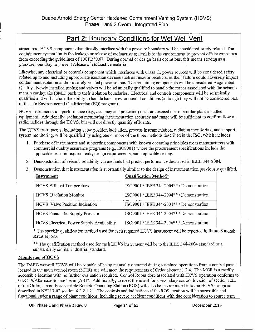
The HCVS instruments, including valve position indication, process instrumentation, radiation monitoring, and supportsystem monitoring, will be qualified by using one or more of the three methods described in the ISG, which includes:
1. Purchase of instruments and supporting components with known operating principles from manufacturers withcommercial quality assurance programs (e.g., ISO900 1) where the procurement specifications include theapplicable seismic requirements, design requirements, and applicable testing.
2. Demonstration of seismic reliability via methods that predict performance described in IEEE 344-2004.
3. Demonstration that instrumentation is substantially similar to the design of instrumentation previously qualified.
Instrument Oualification Method*
HCVS Effluent Temperature IS09001 / IEEE 344-2004** / Demonstration
HCVS Radiation Monitor 1SO9001 I IEEE 344-2004** /Demonstration
HCVS Valve Position Indication IS09001 / IEEE 344-2004** /Demonstrat ion
HCVS Pneumatic Supply Pressure IS09001 / IEEE 344-2004** /Demonstration
HCVS Electrical Power Supply Availability IS09001 / IEEE 344-2004** /Demonstration
* The specific qualification method used for each required HCVS instrument will be reported in future 6 monthstatus reports.
* * The qualification method used for each HCVS instrument will be to the IEEE 344-2004 standard or asubstantially similar industrial standard.
Monitoring of IICVS
The DAEC wetwell HCVS will be capable of being manually operated during sustained operations from a control panellocated in the main control room (MCR) and will meet the requirements of Order element 1.2.4. The MCR is a readilyaccessible location with no further evaluation required. Control Room dose associated with HCVS operation conforms toGDC 19/Alternate Source Term (AST). Additionally, to meet the intent for a secondary control location of section 1.2.5of the Order, a readily accessible Remote Operating Station (ROS) will also be incorporated into the HCVS design asdescribed in NEI 13-02 section 4.2.2.1.2.1. The controls and indications at the ROS location will be accessible andfunctional under a range of plant conditions, including severe accident conditions with due consideration to source teuan
OIP Phase 1land Phase 2 Rev. 0Pae1of6Dcmbr25 December 2015

Duane Arnold Energy Center Hardened Containment Venting System (HCVS)Phase I and 2 Overall Integrated Plan
Part 2: Boundary Conditions for Wet Well Vent
and dose impact on operator exposure, extended loss of AC power (ELAP), and inadequate containment cooling. Anevaluation will be performed to determine accessibility to the location, habitability, staffing sufficiency, andcommunication capability with Vent-use decision makers.
The wetwell HCVS will include means to monitor the status of the vent system in both the MCR and the ROS (viacommunication with the MCR). The ability to open/close the vent system valves multiple times during the event' s first24 hours will be provided by a bank of Nitrogen Bottles and the HCVS uninterruptible power supply. Beyond the first 24hours, the ability to maintain these valves open or closed will be provided with portable replaceable nitrogen bottles andFLEX generators.
The wetwell HCVS will include indications for vent temperature, and effluent radiation levels in the MCR. Otherimportant information on the status of supporting systems, such as local power source status and pneumatic supplypressure, will also be included in the design. The wetwell HCVS includes existing Dmywell pressure and SuppressionPool level indication in the MCR to monitor vent operation. This monitoring instrumentation provides the indication fromthe MCR as per Requirement 1.2.4 and will be designed for sustained operation during an ELAP event.
Component reliable and rugged performance
The EICVS downstream of the second containment isolation valve, including piping and supports, electrical powersupply, valve actuator pneumatic supply, and instrumentation (local and remote) components, will be designed/analyzedto conform to the requirements consistent with the applicable design codes for the plant and to ensure functionalityfollowing a design basis earthquake.
Additional modifications required to meet the Order will be reliably functional at the temperature, pressure, and radiationlevels consistent with the vent pipe conditions for sustained operations. The instrumentation/powersupplies/cables/connections (components) will be qualified for temperature, radiation level, and total integrated doseradiation for the Effluent Vent Pipe.
Conduit design will be installed to Seismic Class 1 criteria. Missile protection will be provided when required (referenceHCVS-WP-04). Augmented quality requirements will be applied to the components installed in response to this Order.
If the instruments are purchased as commnercial-grade equipment, they will be qualified to operate under severe accidentenvironment as requfired by NRC Order EA-13-109 and the guidance of NEJ 13-02. These qualifications will bebounding conditions for DAEC.
For the instruments required after a potential seismic event, the following methods will be used to verify that the designand installation is reliable / rugged and thus capable of ensuring HCVS functionality following a seismic event.Applicable instruments are rated by the manufacturer (or otherwise tested) for seismic impact at levels commensuratewith those of postulated severe accident event conditions in the area of instrument component use using one or more ofthe following methods:
* demonstration of seismic motion will be consistent with that of existing design basis loads at the installedlocation;
* substantial history of operational reliability in enviromnaents with significant vibration with a design envelopeinclusive of the effects of seismic motion impairted to the instruments proposed at the location;
* adequacy of seismic design and installation is demonstrated based on the guidance in Sections 7, 8, 9, and 10 ofIEEE Standard 344-2004, IEEE Recommended Practice for Seismic Qualification of Class JE Equipment forNuclear Power Generating Stations, (Reference 27) or a substantially similar industrial standard;
* demonstration that proposed devices are substantially similar in design to models that have been previouslytested for seismic effects in excess of the plant design basis at the location where the instrument is to be installed(g-levels and fr'equency ranges); or
* seismic qualification using seismic motion consistent with that of existing design basis loading at the installation
OIP Phase 1land Phase 2 Rev. 0Pae1of6Dcmbr25Page 15 of 63 December 2015
Duane Arnold Energy Center Hardened Containment Venting System (HCVS)Phase 1 and 2 Overall Integrated Plan
Part 2: Boundary Conditions for Wet Well Vent
location
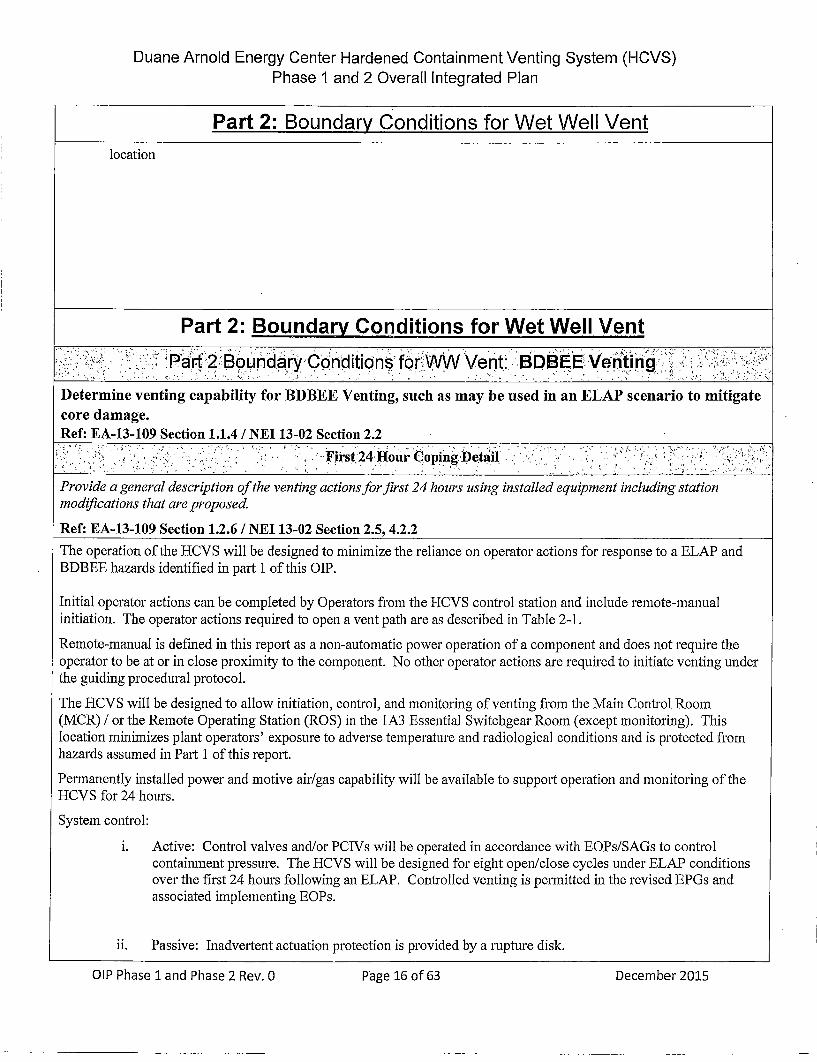
Part 2: Boundary Conditions for Wet Well Venti )":i•i'i:.i •••" •!,:P~art 2 :Bound:arCo~nditions• for WWVent:" :BDBEE! Venfiting•,;' i: i-,;iZ•ii.!i:
Determine venting capability for BDBEE Venting, such as may be used in an ELAP scenario to mitigatecore damage.Ref: EA-13-109 Section 1.1.4 / NEI 13-02 Section 2.2
,,i:- " •; , U ." ,F"rst-"24 Hour Coping, Detail.
Provide a general description of the venting actions for first 24 hours using installed equipment including station
modifications that are proposed.
Ref: EA-13-109 Section 1.2.6 / NEL 13-02 Section 2.5, 4.2.2The operation of the 1{CVS will be designed to minimize the reliance on operator actions for response to a ELAP andBDBEE hazards identified in part 1 of this O]P.
Initial operator actions can be completed by Operators fr'om the HCVS control station and include remote-manualinitiation. The operator actions required to open a vent path are as described in Table 2-1.
Remote-manual is defined in this report as a non-automatic power operation of a component and does not require theoperator to be at or in close proximity to the component. No other operator actions are required to initiate venting underthe guiding procedural protocol.
The HCVS will be designed to allow initiation, control, and monitoring of venting from the Main Control Room(MCR) / or the Remote Operating Station (ROS) in the 1A3 Essential Switchgear Room (except monitoring). Thislocation minimizes plant operators' exposure to adverse temperature and radiological conditions and is protected fromhazards assumed in Part 1 of this report.
Permanently installed power and motive air/gas capability will be available to support operation and monitoring of theHCVS for 24 hours.
System control:
i. Active: Control valves and/or PCTVs will be operated in accordance with EOPs/SAGs to controlcontaimnent pressure. The HCVS will be designed for eight open/close cycles under ELAP conditionsover the first 24 hours following an ELAP. Controlled venting is permitted in the revised EPGs andassociated implementing EOPs.
ii. Passive: Inadvertent actuation protection is provided by a rupture disk.
OIP Phase 1 and Phase 2 Rev. 0 Page 16 of 63 December 2015Page 16 of 63 December 2015

Duane Arnold Energy Center Hardened Containment Venting System (HCVS)Phase I and 2 Overall Integrated Plan
Part 2: Boundary Conditions for Wet Well Vent
A rupture disk will be provided in the vent line downstream of the PCIVs. The rupture disk can beintentionally breached from the Main Control Room or ROS as directed by applicable procedures. ThePCIVs must be open to permit vent flow. The set point of the rupture disk is greater than the maximumexpected primary containment pressure during the design basis LOCA. Therefore, it would not ruptureduring and following a design basis LOCA. The rupture disk is installed to provide a zero-leakagebarrier to prevent PCJV leakage from becoming an unfiltered release to the environment. The rupturedisk also acts as a redundant barrier in the event of inadvertent PCTV actuation.
Provide a general description of the venting actions for greater than 24 hours using portable and installed equipmentincluding station modi~fications that are proposed
Ref: EA-13-109 Section 1.2.4, 1.2.8 / NEI 13-02 Section 4.2.2After 24 hours, available personnel will be able to connect supplemental motive air/gas to the HCVS. Connections forsupplementing electrical power and motive air/gas required for HCVS will be located in accessible areas with reasonableprotection per NiEI 12-06 that minimize personnel exposure to adverse conditions for HCVS initiation and operation.Connections will be pre-engineered quick disconnects to minimize manpower resources. Electrcal power will besupplemented consistent with NRC Order EA-12-049.
These actions provide long term support for HCVS operation for the period beyond 24 hrs. to 7 days (sustained operationtime period) because on-site and off-site personne and resources will have access to the unit(s) to provide needed actionand supplies.
Provide a brief description of Procedures / Guidelines:
Confirm that procedure/guidance exists or will be developed to support implementation.NEI 13-02 §6.1.2
EOP 2 Primary Containment Control Flowchart exists to direct operations in protection and control of containmentintegrity, including use of the existing containment vent system. Other site procedures for venting containment using theHCVS will include: TSG-Appendix C, Technical Support Guidelines "Containment Venting Guidelines" and SEP 301.3"Torus Vent via Hardpipe Vent".
Identify modifications:
List modifications and describe how they support the HCVS Actions.
EA- 12-049 Modifications
* EC 280488 constructed storage facilities for portable equipment storage to protect FLEX equipment fromexternal hazards.
* EC 280490 will add connection points for the 480 volt portable FLEX generator to connect to Motor ControlCenter 1B32. This will allow restoring power to the HCVS uninterruptible power supply.
OIP Phase 1 and Phase 2 Rev. 0Pae1of3Dcmbr25Page 17 of 63 December 2015
Duane Arnold Energy Center Hardened Containment Venting System (HCVS)Phase 1 and 2 Overall Integrated Plan
Part 2: Boundary Conditions for Wet Well Vent
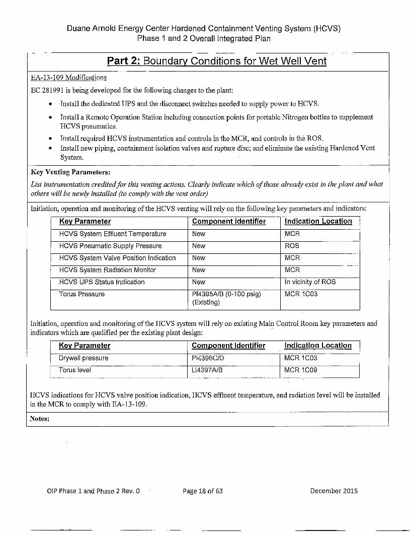
EA- 13-109 Modifications
EC 281991 is being developed for the following changes to the plant:
* Install the dedicated UPS and the disconnect switches needed to supply power to HCVS.
* Install a Remote Operation Station including connection points for portable Nitrogen bottles to supplementHCVS pneumatics.
* Install required HCVS instrumentation and controls in the MCR, and controls in the ROS.o Install new piping, containment isolation valves and rupture disc; and eliminate the existing Hardened Vent
System.
Key Venting Parameters:
List instrumentation credited for this venting actions. Clearly indicate which of those already exist in the plant and whatothers will be newly installed (to comply with the vent order)
Initiation, operation and monitoring of the HCVS venting will rely on the following key parameters and indicators:
Key Parameter Cornponent Identifier Indication Location
HCVS System Effluent Temperature New MCR
HCVS Pneumatic Supply Pressure New ROS
HCVS System Valve Position Indication New MCR
HCVS System Radiation Monitor New MCR
HCVS UPS Status Indication New In vicinity of ROS
Torus Pressure PI4395A/B (0-100 psig) MCR 1003(Existing)
Initiation, operation and monitoring of the HCVS system will rely on existing Main Control Room key parameters andindicators which are qualified per the existing plant design:
Key Parameter Component Identifier Indication Location
Drywell pressure [PI4396C/D MCR 1003
Torus level L14397A/B MCR 1009
HCVS indications for HCVS valve position indication, HCVS effluent temperature, and radiation level will be installedin the MCR to comply with EA-13-109.
Notes:
OIP Phase 1land Phase 2 Rev. 0Pae1of6Dcmbr25 December 2015

Duane Arnold Energy Center Hardened Containment Venting System (HCVS)Phase 1 and 2 Overall Integrated Plan
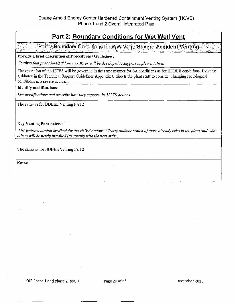
Part 2: Boundary Conditions for Wet Well Ventili ar 2 Boundary Conditions :for VWVent: Severe Accident- Vetinig:: ::;
Determine venting capability for Severe Accident Venting, such as may be used in an ELAIP scenario to mitigatecore damage.
Ref: EA-13-109 Section 1.2.10 / NEI 13-02 Section 2.3
Provide a general description of the venting actions for first 24 hours using installed equipment including stationmodifications that are proposed.
Ref: EA-13-109 Section 1.2.6 / NEI 13-02 Section 2.5, 4.2.2The operation of the HCVS will be designed to minimize the reliance on operator actions for response to an ELAP andsevere accident events. Severe accident event assumes that specific core cooling actions from the FLEX strategiesidentified in the response to Order EA12-049 were not successfully initiated. Access to the reactor building will berestricted as determined by the RPV water level and core damage conditions. Immediate actions will be completed byOperators in the Main Control Room (MCR) or at the HCVS Remote Operating Station (ROS) and will include remote-manual actions. The operator actions required to open a vent path were previously listed in the BDBEE Venting Part 2section of this report (Table 2-1).
Permanently installed power and motive air/gas will be available to support operation and monitoring of the HCVS for 24hours. Specifics are the same as for BDBEE Venting Part 2.
System control:
i. Active: Same as for BDBEE Venting Part 2.
ii. Passive: Same as for BDBEE Venting Part 2.
Provide a general description of the venting actions for greater than 24 hours using portable and installed equipmentincluding station modifications that are proposed.
Ref: EA-13-109 Section 1.2.4, 1.2.8 / NZEI 13-02 Section 4.2.2
Specifics are the same as for BDBEE Venting Part 2 except the location and refueling actions for the FLEX DG andreplacement Nitrogen Bottles will be evaluated for SA environmental conditions resulting fr'om the proposed damagedReactor Core and resultant HCVS vent pathway.
Perform severe accident evaluation for FLEX DG and replacement gas to confirm accessibility for use for post 24 hour
actions (See Attachment 7, Open Item 2).
These actions provide long termn support for HCVS operation for the period beyond 24 hours to 7 days (sustainedoperation time period) because on-site and off-site personnel and resources will have access to the unit to provide neededactions and supplies.
N N' N N N N N
N N N - N. . ~*~N N~NNNNN NN ~N NN N N ~N**~~* N.NNNNNN.;NN~
OiP Phase 1 and Phase 2 Rev. 0 Page 19 of 63 December 2015Page 19 of 63 December 2015
Duane Arnold Energy Center Hardened Containment Venting System (HCVS)Phase 1 and 2 Overall Integrated Plan
Part 2: Boundary Conditions for Wet Well Vent" i ,P~art 2 Boundaryi Con.d~itions for WWVent: Severe.Acciden~t Ven~ting.•!`!`.ii!
Provide a brief description of Procedures / Guidelines:
Confirm that procedure/guidance exists or will be developed to support implementation.
The operation of the H-CVS will be governed in the same maimer for SA conditions as for BDBEE conditions. Existingguidance in the Technical Support Guidelines Appendix C directs the plant staff to consider changing radiologicalconditions in a severe accident..
Identify modifications:
List modifications and describe how they support the HCVS Actions.
The same as for BDBEE Venting Part 2
Key Venting Parameters:
List instrumentation credited for the HCVS Actions. Clearly indicate which of those already exist in the plant and whatothers will be newly installed (to comply with the vent order)
The same as for BDBEE Venting Part 2
Notes:
OIP Phase 1land Phase 2 Rev. O ae2 f6 eebr21Page 20 of 63 December 2015
Duane Arnold Energy Center Hardened Containment Venting System (HCVS)Phase 1 and 2 Overall Integrated Plan
Part 2: Boundary Conditions for Wet Well Vent
• ]i , i ,, !:Par 2 B2,o~ur£idary.Con~ditio ns-for WW.Vent: ,HCVS S~u ppor •Eq upment:tznctions::L -::/•
Determine venting capability support functions needed
Ref: EA-13-109 Section 1.2.8, 1.2.9 / NEL 13-02 Section 2.5, 4.2.4, 6.1.2
Provide a general description of the BDBEE Venting actions support functions. Identif methods and strategy (ies)utilized to achieve venting results.
Ref: EA-13-109 Section 1.2.9 / NEI 13-02 Section 2.5, 4.2.2, 4.2.4, 6.1.2
Containment integrity is initially maintained by permanently installed equipment. All containment venting functions willbe performed from the MCR or ROS.
Venting will require support from the planned dedicated uninterruptable power supply. Before the dedicated UPS isdepleted, portable FLEX diesel generators, as detailed in the response to Order EA-12-049, will be credited to charge theUPS. A bank of Nitrogen bottles, with back-up from portable Nitrogen bottles, will provide sufficient motive force forall HCVS valve operations.
Provide a general description of the Severe Accident Venting actions support functions. Identify methods andslrategy(ies) utilized to achieve venting results.
Ref: EA-13-109 Section 1.2.8, 1.2.9 / NEI 13-02 Section 2.5, 4.2.2, 4.2.4, 6.1.2
The same support functions that are used in the BDBIEE scenario would be used for severe accident venting. Toensure power for 24 hours, a dedicated HCVS uninterruptable power supply will be available to feed HCVS loads. At24 hours, power will be backed up by FLEX generators evaluated for SA accessibility. Portable Nitrogen bottles willbe available as supplemental pneumatic sources.
Provide a brief description of Procedures!/ Guidelines:
Confirm that procedure/guidance exists or will be developed to support implementation.
Most of the equipment used in the HCVS is permanently installed. The key portable items will be the SACapable/FLEX DGs and portable Nitrogen bottles. These will be staged in position for the duration of the event.
Identify modifications.
List modifications and describe how they support the HCTVS Actions.
OIP Phase 1 and Phase 2 Rlev. 0 Pg 1o6 eebr21December 2015
Duane Arnold Energy Center Hardened Containment Venting System (HCVS)' Phase 1 and 2 Overall Integrated Plan
Part 2: Boundary Conditions for Wet Well Vent",,: i : :•Part 2 Boundary conditions for ww Vent: HCGvs SUpport Equipment. Functio:ns,. , ",iii
Same as Part 2
HCVS connections required for portable equipment will be protected from all applicable screened-in hazards and locatedsuch that operator exposure to radiation and occupational hazards will be minimized. Structures to provide protection ofthe HCVS connections will be constructed to meet the requirements identified in NEI-12-06 section 11 for screened inhazards.
Key Support Equipment Parameters:
List instrumentation credited for the support equipnment utilized in the venting operation.Clearly indicate which of those already exist in the plant and what others will be newly installed (to comply with the ventorder)
Local control features of the FLEXDG electrical load and fuel supply (NEW)
UPS Status Indication (NEW)
Pressure gauge on supplemental Nitrogen bottles at ROS (NEW)
Notes:
OIP Phase 1 and Phase 2 Rev. 0Pae2of3Dcmbr01Page 22 of 63 December 2015

DuanArnol Enrg Ceuntedardee Condtainmnt Voentin Syseml (HVS)t
Part 2: Boundary Conditions for Wet Well VentP, art 2- Boundary Condition~s for WW Vent:" HCVS v enting• Portable :Equ~ipment' Depfloymenti :I .
Provide a general description of the venting actions using portable equipment including modifications that are proposedto maintain and/or support safety functions.
Ref: EA-13-109 Section 3.1 / NEI 13-02 Section 6.1.2, D.1.3.1
Deployment pathways for compliance with Order EA-12-049 are acceptable without further evaluation needed except inareas around the Reactor Building or in the vicinity of the HCVS piping. Deployment in the areas around the ReactorBuilding or in the vicinity of the HCVS piping will allow access, operation and replenishment of consumables with theconsideration that there is potential Reactor Core Damage and HCVS operation.
-Details: ,7 ;?2!:Provide a brief description of Procedures / Guidelines:
Confirm that procedure/guidance exists or will be developed to support implementation.
Operation of the portable equipment is the same as for compliance with Order EA-12-049 thus they are acceptablewithout further evaluation
HCVS Actions Modifications Protection of connections
Identify Actions including how Identify mnodifications Identif how the connection is protectedthe equipment will be deployedto the point of use.
Per compliance with Order EA- N/A Per compliance with Order EAI2-049 (FLEX)12-049 (FLEX)
Notes:
OIP Phase 1land Phase 2 Rev. 0Oae2 f6 eebr21Page 23 of 63 December 2015

Duane Arnold Energy Center Hardened Containment Venting System (HCVS)Phase 1 and 2 Overall Integrated Plan
Part 3: Boundary Conditions for EA-1 3-1 09, Option B.2
Licensees that use Option B. 1 of EA-13-] O9 (SA Capable DW Vent without SA WA) must develop their own OIP. Thistemplate does not provide guidance for that option.
Licensees using Option B.2 o f EA-13--10 9 (SA WA and SA WM or 5 45 F SAD W Vent (SAD V) with SA WA) may use thistemplate for their QIP submittal. Both SA WM and SADV require the use of SAWA and may not be done independently.The HCVS actions under Part 2 apply to all of the following.:
This Part is divided into the following sections.'
3.1: Severe Accident Water Addition (SA WA)
3. 1.A: Severe Accident Water Management (SAWM)
3. LB.B: Severe Accident DW Vent (545 deg F) (not used)
DAEC will implement SAWA and SAWM\ in accordance with subpar~t 3.1.A.
Provide a sequence of events- and identify any time conistraint required ,for succe~ss inicluindg thie bass~ii ,Sfor the- tim e c nstir~aint,:. • -::: ::, • ,: ., " • ,i ': . .. i::"~!:: i.••i!/';!:i'l:.':•
SA WA and SAWM or SAD VActions su~pporting SA conditions that have a time constraint to be successful should beidentified with a technical basis and a justification provided that the time can reasonably be met (for example, awalkthrough of deployment). Actions already identified under the HC VS part of this template need not be repeated here.
The time to establish the water addition capability into the RPV or DW should be less than 8 hours from the onset of theloss of all injection sources.
* Electrical generators satisfying the requirements of EA-12-049 may be credited for powering componentsand instrumentation needed to establish a flow path.
* Time Sensitive Actions (TSAs) for the purpose of SAWA are those actions needed to transport, connect andstart portable equipment needed to provide SA WA flow or provide power to SA WA components in the flowpath between the connection point and the RPV or drywell. Actions needed to establish power to SAWAinstrumentation should also be included as TSAs.
Ref: NEI 13-02 Section 6.1.1.7.4.1, 1.1.4, 1.1.5
The operation of the IICVS using SAWA and SAWMISADV will be designed to minimize the reliance on operatoractions in response to hazards listed in Part 1. Initial operator actions will be completed by plant personnel and willinclude the capability for remote-manual initiation from the MCR using control switches, at MCC/Busses in the ControlBuilding and locally in the Turbine Building and the pumphouse. In addition, HCVS operation may occur at the ROS atthe 757'elevation in the Control Building (1A3 essential switchgear room).
Timelines (see Attachment 2.1 .A for SAWA/ SAWM) were developed to identify required operator response times andactions. The timelines are an expansion of Attachment 2A and begin either as core damage occurs (SAWA) or afterinitial SAWA injection is established and as flowrate is adjusted for option B .2 (SAWM). The timelines do not assumethe core is ex-vessel and the actions taken ai'e appropriate for both in-vessel and ex-vessel core damage conditions.
OIP Phase 1 and Phase 2 Rev. 0Pae2of3Dcmbr01Page 24 of 63 December 2015

DuaeAnolPEnrgCeter. Hardnedar Condtainmnt Venin Sysem(HVS
Part 3.1: Boundary Conditions for SAWATal 3.1 2 SAW Manua Actions :':', i Q :,
Primary Action Primary Location / Component Notes1. Establish HCVS capability in U MCR or ROS U Applicable to SAWA/SAWM
accordance with Part 2 of this strategyguidance.
2. Establish RPV flow path: U RB SECR- FLEX RPV Actions are required within 1 hourmanually open FLEX RPV injection valves V20-0 126 after initiation of the event (SBOinljection valves V20-0 126 and and V20-0 127. with no injection source) due toV20-0 127, manually (partially) U RB RHR valve room- RB accessibility.open MO2003 to pass the MO2003.required SAWA flow.
3. Strip electrical loads from MCC U RB 786' MCC 1B34 U This action will allow power to be1B34. Leave breakers closed for restored to 1B34 without anMO2003 A LPCI Inject Valve, overcurrent trip. This action shallMO2005 A RIIR Torus Spray! be performed within 1 hour due toTorus Cooling Isolation Valve, RB accessibility.and MO2010 RHIR Cross-tie U Closing breakers for M02003,Isolation Valve. MO2005, and MO2010 will
ensure that the RIHR injection pathcan be aligned from the MCR forall conditions.
4. Connect FLEX (SAWA) pump to U Circulating Water Pit at Non-flood condition, portablewater source Pumnphouse (non-flood diesel pump is staged at the
condition) or Condenser Pumphouse with suction firom theHotwell (flood condition). Circulating Water Pit. Flood
condition, portable diesel pump isstaged in the Turbine Buildingsouth rail bay, with suctionconnected to the CondenserHotwell.
5. Connect FLEX (SAWA) pump U Route flexible hose fromdischarge to injection piping pump discharge to hard pipe
connection in TurbineBuilding Heater Bay (757')
6. Power up RHR valves with EA- U Control Building 757', 1A3 U Should be done as soon as12-049 (FLEX) generator. Switchgear Room. possibleProvide power to 1B03, close U RI-R valves may be operated U Due to load stripping at 1B34,breaker 1B303 to supply power to from the main control room MO2003, MO2005, and MO20101B34. can be operated from the MCR.
OIP Phase 1land Phase 2 Rev. 0Pae2of6Dcmbr01Page 25 of 63 December 2015

Duane Arnold Energy Center Hardened Containment Venting System (HCVS)Phase 1 and 2 Overall Integrated Plan
Part 3.1: Boundary Conditions for SAWA
7. Align 'A' RHR injection path as U MCR handswitches. If torus cooling was operating atrequired- open MO2003. the time of the event, isolate A
loop by closing M02005; isolateB Loop by closing MO20 10.
8. Inject to RPV using FLEX Local flow indicator at FLEX U Initial SAWA injection rate is 272(SAWA) pump (SAWA) pump. gpm. (Flowrate is determined by
scaling, a ratio of the plantspecific thermal power rating tothe reference plant power level,
multiplied by 500 gpm).9. Monitor SAWA indications Locally at FLEX (SAWA) Pump flow and flow control valve
__________________ pump. position10. Use SAWM to maintain U MCR and locally at FLEX U Monitor DW Pressure and
availability of the WW vent (Part (SAWA) pump. Suppression Pool Level in MCR3.1 .A) U Control SAWA flow at pump skid
D:Iiscussi-on o 6timeline SAWA~identtified itms.:,........- " "":
HCVS operations are discussed under Phase I of EA-13-109 (Part 2 of this OIP).
* Within 1 hour, implement required manual actions in the Reactor Building. Specifically, open RPV injectionvalves V20-0 126 and V20-0 127 in SECR, open (approximately 25%) MO2003 'A' LPCI Injection Valve in RIIRValve Room, and strip loads on 1B34 at RB 786'.
* Less than 8 Hours - Establish electrical power and other EA-12-049 actions needed to support the strategies forEA-13-109, Phase 1 and Phase 2. Action being taken within the reactor building under EA-12-049 conditions afterRPV level lowers to 2/3 core height must be evaluated for radiological conditions assuming permanentcontainment shielding remains intact. (HCVS-FAQ-12) All other actions required are assumed to be in-line withthe FLEX timeline submitted in accordance with the EA-12-049 requirements.
* Less than 8 Hours - Initiate SAWA flow to the RPV. Having the HCVS in service will assist in minimizing thepeak DW pressure during the initial cooling conditions provided by SAWA.
Determine operating requirements for SA WA, such as may be used in an ELAP scenario to mitigate core damage.
Ref: EA-13-109 Attachment 2, Section B.2.2, B.2.3 / NEI 13-02 Section 1.1.6, 1.1.4.4
It is anticipated that SAWA will be used in Severe Accident Events based on presumed failure of injection systems orpresumed failure to implement an injection system in a timely manner leading to core damage. This does not precludethe use of the SAWA system to supplement or replace the EA-12-049 injection systems if desired. SAWA will consistof both portable and installed equipment.
The motive force equipment needed to support the SAWA strategy shall be available prior to t=8 hours from the loss of
alp Phase 1 and Phase 2 Rev. 0 Page 26 of 63 December 2015December 2015

Duane Arnold Energy Center Hardened Containment Venting System (HCVS)Phase I and 2 Overall Integrated Plan
Part 3.1: Boundary Conditions for SAWA
injection (assumed at T=0).
The SAWA flow path includes methods to minimize exposure of personnel to radioactive liquids / gases and potentiallyflammable conditions by inclusion of backflow prevention. RHIR LPCI injection mode has installed ECCS backflowprevention devices (V20-0082 A RHIR LPCI Injection Loop Check Valve) qualified for accident scenarios.
Description of SAWA actions for first 24 hours:
T<I hir:
* No evaluation required for actions inside the reactor building for SAWA. Expected actions in the RB are:o RB SECR- manually open FLEX RPV injection valves V20-0 126 and V20-0 127.o RB RTTR valve room- manually open MO2003 approximately 25%.o RB 786' south side, strip electrical loads fr'om MCC 1B34. Leave breakers closed for MO2003 A
LPCI Inject Valve, MO2005 A RIIR Torus Spray!/Torus Cooling Isolation Valve, and MO2010RH-IR Cross-tie Isolation Valve.
T=Il- 8hr:
* Evaluation of core gap and early in vessel release impact to reactor building access for SAWA actions isrequired. It is assumed that reactor building access is limited due to the source tern at this time unlessotherwise noted. (Refer to HCVS-FAQ-12 for actions in T=1-7 hr) Expected actions are:
o No actions are expected in the RB.
* Establish electrical power for SAWA systems and indications using FLEX strategies (EA-12-049).
o Step 6 of table 3.1 above
* Establish flow to the RPV using SAWA systems. Begin injection at a maximum rate, not to exceed 272gpm.
o Steps 3, 4, 7, and 8 of table 3.1 above
* Monitor SAWA indications
o Step 9 of table 3.1 above
T<8 -12 hr:
* Continue injection for 4 hours after SAWA injection begins at initial SAWA rate.
T_<12 hrs:
* Proceed to SAWM actions (Part 3.1 .A)
o Step 10 of table 3.1 above.
o Reduce RPV injection flow to approximately 55 gpm.
o Monitor DW pressure and Suppression Pool level in MCR; adjust RPV injection flow as needed tomaintain a stable or lowering Suppression Pool level.
i':""::i"';•) i:i';.ii' •,ii :". ,) "" """Greater Than ,24 Hourl ,Coping D~etail - :"" "' ;':7,.,.?-.,•:-.-,.. .,.,:,
OIP Phase 1 and Phase 2 Rev. 0Pge2of6Dcmbr01 December 2015
Duane Arnold Energy Center Hardened Containment Venting System (HCVS)Phase I and 2 Overall Integrated Plan
Part 3.1: Boundary Conditions for SAWA
Provide a general description of the SA WA actions for greater than 24 hours using portable and installed equipmnentincluding station modifications that are proposed.
Ref: EA-13-109 Attachment 2, Section B.2.2, B.2.3/ NEI 13-02 Section 4.2.2.4.1.3.1, 1.1.4,
SAWA Operation is the same for the full period of sustained operation. If SAWM is employed flow rates will bedirected to preserve the availability of the HCVS wetwell vent (see 3.1 .A).
: "..-. , ,.. .:•4 :, : .: . . . , ... • ! . , . . D etails:' ". . .. ' , • " ,, . .... .- '
Details of Design Characteristics/Performance Specifications
SA WA shall be capable of providing an PP V injection rate of/2 72 gpm within 8 hours of a loss of all PP V injectionfollowing an ELAP/Severe Accident. SA WA shall meet the design characteristics of the HCVS with the exception of thededicated 24 hour power source. Hydrogen mitigation is provided by backfiow prevention for SA WA.
Ref." EA-13-109 Attachment 2, Section B.2.1, B.2.2, B.2.3/ NEI 13-02 Section 1.1.4
Equipment Locations/Controls/Instrumentation
The locations of the SAWA equipment and controls, as well as ingress and egr'ess paths will be evaluated for theexpected severe accident conditions (temperature, humidity, radiation) for the Sustained Operating period. Equipmentwill be evaluated to remain operational throughout the Sustained Operating period. Personnel exposure and temperature/ humidity conditions for operation of SAWA equipment will not exceed the limits for ERO dose and plant safetyguidelines for temperature and humidity.
Equipment staging locations and system configuration will be different, depending on flood vs. non-flood conditions.
In a Non-Flood Condition:
In the non- flood condition, the FLEX (SAWA) pump is staged at the Pumphouse. The pump hasminimum flow capability, which also provides freeze protection. The pump suction is connected to anexisting standpipe in Circulation Water pit on the east side of the Pumphouse. The discharge hose isconnected to a flow indicator in the pmnp outlet, routed to the Turbine Building north truck bay, throughthe Turbine Building to the connection point in the Turbine Building Heater Bay. This connection willhave a mating connector and a manual isolation valve. This piping routes through the Turbine Building!Reactor Building wall, into the RB Southest Corner Room (SECR), and ties into the "A" RHR Loop viatwo 4" manual isolation valves (FLEX RPV injection point). Refer to Sketch 3 for the conceptuallayout of the SAWA flowpath and connections. Once the SAWA components are deployed andconnected, the SAWA flow path is completed by opening the A RI'HR LPCI Injection Valve (MO2003).MO2003 is the normally closed injection valve, and will be manually or electrically opened in SAWAconditions. Backflow prevention is provided by the A RHIR LPCI Injection Loop Check Valve V20-0082.
Cross flow into other portions of the RHIR system will be isolated by ensuring closure of the other MotorOperated Valves (MOVs). Select RHR MOVs will be powered from the FLEX DG via 1B03/ 1B303/1B34. This will provide the capability to realign RITR if needed (i.e. if torus cooling mode wasoperating at the time of the event).
DW pressure and Suppression Pool level will be monitored and flowrate will be adjusted by use of the
OIP Phase 1 and Phase 2 Rev. 0Pae2of3Dcmbr01Page 28 of 63 December 2015

Duane Arnold Energy Center Hardened Containment Venting System (HCVS)Phase 1 and 2 Overall Integrated Plan
Part 3.1: Boundary Conditions for SAWA
flow control valve at the FLEX (SAWA) pump. Communication will be established between the MCRand the FLEX (SAWA) pump location.
MOVs and contailnment instrumentation required for SAWA will be powered by the FLEX dieselgenerators, connected at the Control BUilding essential switchgear room as described in the EA-12-049compliance documents. The FLEX DGs will be located on the north side of the Turbine Building,which is a significant distance from the HCVS (> 200 feet) and are on the opposite side of the buildings(vent is located on the south side of the Reactor Building). Refueling of the FLEX DG and FLEX(SAWA) pump will be accomplished using the established FLEX procedures, and will account for doserates and area accessibility. The Pumphouse is a significant distance away from the HCVS, andsubstantial structural shielding is provided at this location.
In a Flood Condition:
In a flood condition, the FLEX (SAWA) pump is staged in the south Turbine Building rail bay. Theflow path takes suction fr'om the Main Condenser Hotwell. The pump suction is connected to theHotwell condenser bypass line via a hard pipe branch, manual isolation valve, and connection point inthe TB 1 st floor Heater Bay. Hose will be run fr'om this connection point to the south Turbine BuildingRail bay area and connected to the pump inlet. The pump discharge hose will be connected and routedto the FLEX RPV injection point, at the TB 1 st floor Heater Bay. Refer to Sketch 3 for the conceptuallayout of the SAWA flowpath and connections.
At this point, the injection flow path is the same as the Non-Flood condition (through the A RHIR LPCIinjection line), as described above. Available electrical power and instrumentation are the same asdescribed for the non-flood condition.
The location of the FLEX (SAWA) pump in the rail bay is such that radiation shielding is provided bythe RB and TB structures. Note that in the flood condition, the pump will be staged in advance.Operation and refueling will be performed in relatively low dose areas (i.e. < 100 mrern/hr).
Evaluations for projected SA conditions (radiation / temperature) will be performed to ensure that personnel cancomplete the initial and support activities without exceeding the ERO-allowable dose for equipment operation or sitesafety standards. (reference HCVS-WP-02, Plant-Specific Dose Analysis for the Venting of Containment during the SAConditions)
Electrical equipment and instrumentation will be powered fr'om the existing station batteries, and fl'omn AC distributionsystems that are powered from the EA-12-049 generator(s). The battery chargers are also powered from the EA-12-049generator(s) to maintain the battery capacities during the Sustained Operating period. The indications include (* areminimum)
Parameter Instrument Location Power Source / Notes
*DW Pressure P143 96C/D MCR, 1 C03 Instrument AC(Station batteries viaEA- 12-049 generator)
*Suppression Pool Level L14397A/B (l.5'-16') MCR, 1C03, 1C09 Instrument ACLR43 96A/B (Station batteries via(Narrow range 1.5'-16'
Page 29 of 63 December 2015

Duane Arnold Energy Center Hardened Containment Venting System (HCVS)Phase 1 and 2 Overall Integrated Plan
Part 3.1: Boundary Conditions for SAWA
IWide range 0'-98') 11EA-12-049 generator)1
*SAWA Flow FLEX (SAWA) Pump FLEX (SAWA) FLEX (SAWA) pumpFlow indicator Pump Skid (skid mounted device,
mechanical, noelectrical powerrequired)
Motor Operated Valve MCR Panels MCR and Control MO2003controls Building MO2005
MO2010
The instr'umentation and equipment being used for SAWA and supporting equipment has been evaluated to perform forthe Sustained Operating period under tbe expected radiological and temperature conditions.
Equipment Protection
The FLEX (SAWA) pump suction and injection connections are in the Turbine Building Heater Bay and CondenserBay. The concrete shield wall on the south side of the Heater Bay provides a substantial and robust barrier to windgenerated missiles. The Turbine Building is not a seismic Class 1 structure. DAEC UFSAR section 3.8.4.3.3 states:"Although the turbine building, with the exception of that portion which houses the emergency diesel generators, isclassified as Non-seismic, the criteria for Seismic Category I structures were used for the structural design of the entirebuilding. A complete dynamic analysis has been conducted for the turbine building to ensure the integrity of SeismicCategory I equipment within the building and Seismic Categoiy, I equipment and structures adjacent to it." Therefore,the SAWA connection points in the Turbine Building are expected to be available after a seismic event. Portableequipment used for SAWA implementation will meet the protection requirements for storage in accordance with thecriteria in NEI 12-06.
Ref: EA-13-109 Attachment 2, Section B.2.2, 1B.2.3 / NiEI 13-02 Section 5.1.1, 5.4.6, 1.1.6- . -V . .. < !. , ., i,.• •i . 1 •, , , , . ? " : . , , V. . ,.'.... :, , . . .. : -, _ , , .'.. :• : :: . • : , A,. •, :; • ,5 ,:
Provide a brief description of Procedures / Guidelines:Confirm that procedure/guidance exists or will be developed to support implementation.
Ref: EA-13-109 Attachment 2, Section A.3.1, B3.2.3 / NEI 13-02 Section 1.3, 6.1.2
[Provide a brief description of Procedures / Guidelines." to be used for SA WA, likely an ESG]
Procedures will be developed to provide instructions for implementing SAWA. These procedures address the followingactions:
* Perform 1 hour required actions in Reactor Building:o Open manual valves at RPV injection point (V20-0 126, V20-0 127)o Manually open M02003 A RIIR LPCI Inject Valveo Strip loads on 1B34
* Stage FLEX (SAWA) pump, run hoses, connections at suction and injection points (use FLEX procedure)* Stage FLEX diesel generators for power to instruments and 1B03 (use FLEX procedure)* Close breaker 1B303 to power 1B34
OIP Phase 1land Phase 2 Rev. 0Pae3of3Dcmer21 December 2015
Duane Arnold Energy Center Hardened Containment Venting System (HCVS)Phase 1 and 2 Overall Integrated Plan
Part 3.1: Boundary Conditions for SAWA* Align RIIR system MOVs as required* Start FLEX (SAWA) pump, initiate injection, adjust flow to 272 gpm using skid mounted flow control valve and
flow indicator* Sustain RPV injection of 272 gpm for 4 hours* Monitor DW pressure and SP water level, adjust injection rate to 55 gpm or flowrate required to maintain stable
SP level.
Identify modifications:
List mnodifications and describe how they support the SA WA Actions.
Ref: EA-13-109 Attachment 2, Section B.2.2, / NEI 13-02 Section 4.2.4.4, 7.2.1.8, Appendix I
A modification will be required to route the planned RI-IR FLEX injection point to an accessible location outside of theReactor Building. The conceptual design is to add 4" piping to the existing injection line (leaving V20-0 126 and V20-0127 in place), route the line from the RB SECR to the TB Heater Bay (via core bore thr'ough RB/TB wall), terminatedat a new manual isolation valve and mating connector.
Component Qualifications:
State the qualification used for equipment supporting SA WA
Ref: EA-13-109 Attachment 2, Section B.2.2, B.2.3 / NEL 13-02 Section 1.1.6
Permanently installed plant equipment shall meet the same qualifications as described in Part 2 of this OIP.Temporary/Portable equipment shall be qualified and stored to the same requirements as FLEX equipment as specifiedin NEI 12-06. SAWA components are not required to meet NEI 13-02, Table 2-1 design conditions.
Notes:
None
alP Phase 1 and Phase 2 Rev. 0Pae3of3Dcmbr21Page 31 of 63 December 2015

Duane Arnold Energy Center Hardened Containment Venting System (HCVS)Phase 1 and 2 Overall Integrated Plan
Part 3.1.A: Boundary Conditions for SAWAISAWM
STim~eperiods• for• the m'aintaining.SAWM actions :such tha~t the: WW ent " , ! 'i'[; '- ,i:.) ,.•o! .-;,i:>.-
SA WMActions supporting SA conditions that have a time constraint to be successful should be identified with atechnical basis and a justification provided that the time can reasonably be met (for example, a walkthrough ofdeployment). Actions already identified under the HCVS part of this template need not be repeated here.
There are three time periods for the maintaining SA WM actions such that the WW vent remains available to removedecay heat from the containment:
* SA WMcan be maintained for > 7 days without the need for a drywvell vent to maintain pressure below PCPLor containment design pressure, whichever is lower.o Under this approach, no detail concerning plant modifications or procedures is necessary with respect
to how alternate containment heat removal will be provided.* SA WMcan be maintained for at least 72 hours, but less than 7 days before DWpressure reaches PCPL or
design pressure, whichever is lower.o Under this approach, a functional description is required of how alternate containment heat removal
might be established before D Wpressure reaches PCPL or design pressure whichever is lower. Underthis approach, physical plant modifications and detailed procedures are not necessary, but writtendescriptions of possible approaches for achieving alternate containment heat removal and pressurecontrol will be provided.
* SA WM can be maintained for <72 hours SAWM strategy can be implemented but for less than 72 hoursbefore DW pressure reaches PCPL or design pressure whichever is lower.o Under this approach, a functional description is required of how alternate containment heat removal
might be established before D Wpressure reaches PCPL or design pressure whichever is lower. Underthis approach, physical plant modifications and detailed procedures are required to be implemented toinsure achieving alternate containment heat removal and pressure control will be provided for thesustained operating period.
Ref: NEL 13-02 Appendix C.7
For DAEC, SAWM can be maintained for >7 days without the need for a drywell vent to maintain pressure below PCPL(53 psig).
Bas'is for sAW M ti e frm I "i:..[::i i i . . .... . .. ...
_Option 1 - SAWM can be maintained for greater than 7 days: DAEC is bounded by the evaluations performed inBWROG TP-15-008 and representative of the reference plant in NEI 13-02 figures C-2 through C-6. (C.7.1.4.1)
Instrumentation relied upon for SAWM operations is D1rywell Pressure, Suppression Pool level and SAWA flow. All ofthe required instruments are initially powered by the station batteries and then by the FLEX (EA- 12-049) generatorwhich is placed in-service prior to RPV breach. The DG will provide power throughout the Sustained Operation period(7 days). FLEX (SAWA) pump flow is monitored using a mechanical flow element!/indicator. DW Temperaturemonitoring is not a requirement for compliance with Phase 2 of the order, but some knowledge of temperaturecharacteristics provides information for the operation staff to evaluate plant conditions under a severe accident andprovide confirmation to adjust SAWA flow rates. (C.7.l.4.2, C.8.3.1)
Suppression Pool level indication is maintained throughout the Sustained Operation period, so the HCVS remains in-service. The time to reach the level at which the WW vent must be secured is >7days using SAWM flowrates (C.6.3,C.7. 1.4.3)
OIP Phase 1land Phase 2 Rev. 0Pae3of3Dcmbr21Page 32 of 63 December 2015
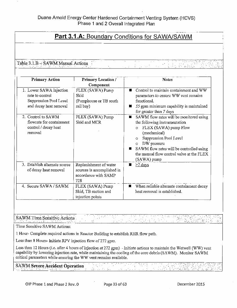
Duane Arnold Energy Center Hardened Containment Venting System (HCVS)Phase 1 and 2 Overall Integrated Plan
Part 3.I.A: Boundary Conditions for SAWAISAWM
Primary Action Primary Location / NotesComponent
1. Lower SAWA injection FLEX (SAWA) Pump U Control to maintain containment and WWrate to control Skid parameters to ensure WW vent remainsSuppression Pool Level (Pumphouse or TB south functional.and decay heat removal rail bay) U 55 gpm minimum capability is maintained
for greater than 7 days2. Control to SAWM FLEX (SAWA) Pump U SAWM flow rates will be monitored using
flowrate for containment Skid and MCR the following instrumentationcontrol / decay heat o FLEX (SAWA) pump Flowremoval (mechanical)
o Suppression Pool Levelo DW pressure
U SAWM flow rates will be controlled usingthe manual flow control valve at the FLEX(SAWA) pump
3. Establish alternate source Replenishment of water U >7 day~sof decay heat removal sources is accomplished in
accordance with SAMIP728
4. Secure SAWA / SAWM FLEX (SAWA) Pump U When reliable alternate containment decaySkid, TB suction and heat removal is established.
________________________injection points ______________________
'SAWMTime Sensitiv•e Actions.. . .. ":.. .. ... •': " • •... "'•
Time Sensitive SAWM Actions:
1 Hour- Complete required actions in Reactor Building to establish RHIR flow path.
Less than 8 Hours- Initiate RPV injection flow of 272 gpm.
Less than 12 Hours (i.e. after 4 hours of injection at 272 gpmn) - Initiate actions to maintain the Wetwell (WW) ventcapability by lowering injection rate, while maintaining the cooling of the core debris (SAWM). Monitor SAWMcritical parameters while ensuring the WW vent remains available.
SSAW M Severe A en .O eraicci. ..de.. ...nt Operation: . , :•:.,.:.• .., .:•.'i.")":)::")•:,.}.•i[:•:. ;,,:•: -,.;-!,::!.::
alP Phase 1land Phase 2 Rev. 0Pae3of6Dcmbr21Page 33 of 63 December 2015

Duane Arnold Energy Center Hardened Containment Venting System (HCVS)Phase 1 and 2 Overall Integrated Plan
Part 3.1 .A: Boundary Conditions for SAWAISAWM
Determine operating requirements for SA WM,1 such as may be used in an ELAP scenario to mitigate core damage.
Ref: EA-13-109 Attachment 2, Section B.2.2, B.2.3 / NEIl 13-02 Appendix C
It is anticipated that SAWM will only be used in Severe Accident Events based on presumed failure of plant injectionsystems per direction by the plant SAMGs. Refer to attachment 2.1 .D for SAWM SAMG language additions.
.".'• .' :! ~..': !".", .i": !' ii .First 24 Hour Coping Detail': " . , ".::!'i!••: :'"-.•,• ..,:
Provide a general description of the £A WM actions for first 24 hours using installed equipment including station
modifications that are proposed
Given the initial conditions for EA-13-109:~
* BDBEE occurs with ELAP* Failure of all injection systems, including steam-powered injection systems
Ref: EA-13-109 Section 1.2.6, Attachment 2, Section B.2.2, 13.2.3 / NEL 13-02 2.5, 4.2.2, Appendix C, Section C.7
SAWA will be established as described as stated above. SAWM will use the installed instrumentation to monitor andadjust the flow from SAWA to control the pump discharge to deliver flowrates applicable to the SAWM strategy.
Once the SAWA initial flow rate has been established for 4 hours, the flow will be reduced while monitoring DWpressure and Suppression Pool level. SAWM flowrate can be lowered to maintain containment parameters and preservethe WW vent path. SAWM will be capable of injection for the period of Sustained Operation.
";, .,':. ii."ii~•i•::- V Greater Th.aGraern..2 ha.,.:4HU4 CpngDHalr , ,n -ir , .,.. , : •' . ,"op, ing ;,:'"" -,De.tail• '' i,!.,,
Provide a general description of the SA WM actions for greater than 24 hours using portable and installed equipmnentincluding station modifcations that are proposed.
Ref: EA-13-109 Section 1.2.4, 1.2.8, Attachment 2, Section B.2.2, 13.2.3 / NEI 13-02 Section 4.2.2, Appendix C,Section C.7
SAWM can be maintained >7 days:
The SAWM flow strategy will be the same as the first 24 hours until 'alternate reliable containment heat removal andpressure control' is reestablished. SAWM flow strategy uses the SAWA flow path. No additional modifications arebeing made for SAWM.
Details of Design Characteristics/Performance Specifications
Ref." EA-13-109 Attachment 2, Section B.2.2, B3.2.3 / NEI 13-02 Section Appendix C
SAWM shall be capable of monitoring the containment parameters (DW pressure and Suppression Pool Level) toprovide guidance on when injection rates shall be reduced, until alternate containment decay heat/pressure control isestablished. SAWA will be capable of injection for the period of Sustained Operation.
December 2015
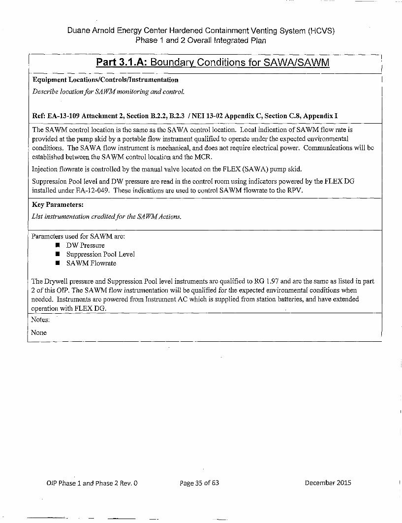
Duane Arnold Energy Center Hardened Containment Venting System (HCVS)Phase 1 and 2 Overall Integrated Plan
Part 3.1 .A: Boundary Conditions for SAWA/SAWMEquipment Locations/Controls/lnstrumentation
Describe location for SA WM monitoring and contfrol.
Ref: EA-13-109 Attachment 2, Section B.2.2, B.2.3 / NET 13-02 Appendix C, Section C.8, Appendix I
The SAWM control location is the same as the SAWA control location. Local indication of SAWM flow rate isprovided at the pump skid by a portable flow instrument qualified to operate under the expected environmentalconditions. The SAWA flow instrument is mechanical, and does not require electrical power. Communications will beestablished between the SAWM control location and the MCR.
Injection flowrate is controlled by the manual valve located on the FLEX (SAWA) pump skid.
Suppression Pool level and DW pressure are read in the control room using indicators powered by the FLEX DGinstalled under EA-12-049. These indications are used to control SAWM flowrate to the RPV.
Key Parameters:
List instrumentation credited for the SA WMActions.
Parameters used for SAWM are:* DW Pressure* Suppression Pool Level* SAWM Flowrate
The D1rywell pressure and Suppression Pool level instruments are qualified to RG 1.97 and are the same as listed in part2 of this OIP, The SAWM flow instrumentation will be qualified for the expected environmental conditions whenneeded. Instruments are powered from Instrument AC which is supplied from station batteries, and have extendedoperation with FLEX DG.
Notes:
None
OIP Phase 1 and Phase 2 Rev. 0Pae3of6Dcmbr25 December 2015
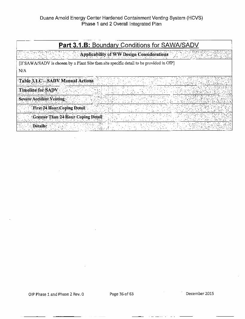
Duane Arnold Energy Center Hardened Containment Venting System (HCVS)Phase 1 and 2 Overall Integrated Plan
Part 3.1.B: Boundary Conditions for SAWA/SADV':'' .," -• :•.•:','- -.. •, Applicali]ty. ofW W, g¢DesignConsiderations : • ,"-.".:"-.;'.:. .i'."
['If SAWAISADV is chosen by a Plant Site then site specific detail to be provided in 0Ih]
N/A
T, able"":• ,t '..' '• ,' ,.1.C.. SA D V M anua A ctions." .•.},• .- • ," ' : .. ,; " ,.•' ".- -,'•'•' •"••,: ',,,.•:•',t•L.,'•• .•z':;-'. "'',
OIP Phase 1land Phase 2 Rev. 0Pae3of6Dcmbr21 December 2015
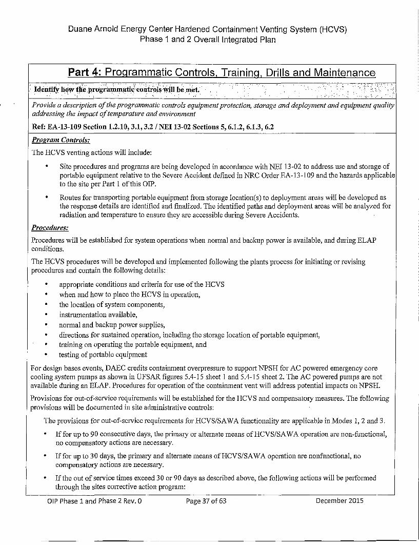
Duane Arnold Energy Center Hardened Containment Venting System (HCVS)Phase 1 and 2 Overall Integrated Plan
Part 4" Procgrammatic Controls, Trainingi, Drills and MaintenanceIdentiyhow the programmati•c'cntrols wiillbe met.: "'.. "- :.. .. ,"'"; :"- '<:'•
Provide a description of the programmatic controls equipnment protection, storage and deployment and equipment qualityaddressing the impact of temperature and environment
Ref: EA-13-109 Section 1.2.10, 3.1, 3.2 / NIEL 13-02 Sections 5, 6.1.2, 6.1.3, 6.2
P,'ogramn Controls:
The HCVS venting actions will include:
* Site procedures and programs are being developed in accordance with NEI 13-02 to address use and storage ofportable equipment relative to the Severe Accident defined in NRC Order EA- 13-109 and the hazards applicableto the site per Part 1 of this OIP.
* Routes for transporting portable equipment from storage location(s) to deployment areas will be developed asthe response details are identified and finalized. The identified paths and deployment areas will be analyzed forradiation and temperature to ensure they are accessible during Severe Accidents.
Procedures:
Procedures will be established for system operations when normal and backup power is available, and during ELAPconditions.
The HCVS procedures will be developed and implemented following the plants process for initiating or revisingprocedures and contain the following details:
* appropriate conditions and criteria for use of the H-CVS* when and how to place the HCVS in operation,* the location of system components,* instrumentation available,* normal and backup power supplies,* directions for sustained operation, including the storage location of portable equipment,* training on operating the portable equipment, and* testing of portable equipment
For design bases events, DAEC credits containment overpressure to support NPSH for AC powered. emergency corecooling system pumps as shown in UFSAR figures 5.4-15 sheet 1 and 5.4-15 sheet 2. The AC powered pumps are notavailable during an ELAP. Procedures for operation of the containment vent will address potential impacts on NPSI{.
Provisions for out-of-service requirements will be established for the HCVS and compensatoly measures. The followingprovisions will be documented in site administrative controls:
The provisions for out-of-service requirements for HCVS/SAWA functionality are applicable in Modes 1, 2 and 3.
* If for up to 90 consecutive days, the prilnaly or alternate means of HCVS/SAWA operation are non-functional,no compensatory actions are necessaly.
* If for up to 30 days, the primaary and alternate means of HCVS/SAWA operation are nonfunctional, nocompensatory actions are necessamy.
* If the out of service times exceed 30 or 90 days as described above, the following actions will be performedthrough the sites corrective action program:
Page 37 of 63 December 2015

Duane Arnold Energy Center Hardened Containment Venting System (HCVS)Phase 1 and 2 Overall Integrated Plan
Part 4" Progqrammatic Controls, Trainingl, Drills and Maintenance
o The cause(s) of the non-functionalityo The actions to be taken and the schedule for restoring the system to functional status and prevent
recurrenceo Initiate action to implement appropriate compensatory actions, ando Restore full HCVS functionality at the earliest oppor'tunity not to exceed one full operating cycle.
Dee crbscribe i i gt . .. ..rainin. ..g pl'an •- " , , , :• :?,, .. :;'... : "• : • ::,... , • .:••:
List training plans for affected organizations or describe the plan for training development
Ref: EA-13-109 Section 3.2 / NEI 13-02 Section 6.1.3
Personnel expected to perform direct execution of the IICVS/SAWA/SAWM actions will receive necessary training inthe use of plant procedures for system operations when normal and backup power is available and during ELAPconditions. The training will be refreshed on a periodic basis and as any changes occur to the HCVS/SAWA/SAWMactions, systems or strategies. Training content and frequency will be established using the Systematic Approach toTraining (SAT) process.
Identfify how the drills and exercise paraimeters will he met.-" ,".. ... " , ,,' .!i ",.:),,.,':
Alignment with NEI 13-06 and 14-0] as codified in NTTF Recommendation 8 and 9 rulemaking
The Licensee should demonstrate use of the HCVS/SA WA/SA WM system in drills, tabletops, or exercises as follows:
•Hardened containment vent operation on nornial power sources (no ELAP).
* During FLEX demonstrations (as required by EA-12-049: Hardened containment vent operation on backuppower and from primary or alternate location during conditions of ELAP/loss of UHS with no core damage.System use is for containment heat removal AND containment pressure control.
* HCVS operation on backup power and from primary or alternate location during conditions of ELAP/loss ofUHS with core damage. System use is for containment heat removal AND containment pressure control withpotential for combustible gases (Demonstration may be in conjunction with SAG change).
* Operation for sustained period with SAWA and SA WMto provide decay heat removal and containment pressurecontrol
Ref: EA-13-109 Section 3.1 / NET 13-02 Section 6.1.3
The site will utilize the guidance provided in NEI 13-06 and 14-0 1 for guidance related to drills, tabletops, or exercisesfor HCVS operation. In addition, the site will integrate these requirements with compliance to any rulemaking resultingfrom the NTTF Recommendations 8 and 9.
Descrimbe t n emai iil enance plan.: .-. " ,i 'ii.•.I"!:' ! "'.i •:'i ,;.``.``:.-`f`j !`.•.:`•• •• .``...`•.•)•.,'::•.i •'i:, .+.:. .
Describe the elements of the maintenance plan
• The maintenance program should ensure that the HCVS/SA WA/SA WM equipment reliability is being achieved in amanner similar to that required for FLEX equipmnent. Standard industry templates (e.g., EPRI) and associated basesmay be developed to define specific maintenance and testing.
o Periodic testing and frequency should be determined based on equipnment type, expected use andmanufacturer's recommendations (further details are provided in Part 6 of this document).
o Testing should be done to verify' design requirements and/or basis. The basis should be documented and
Page 38 of 63
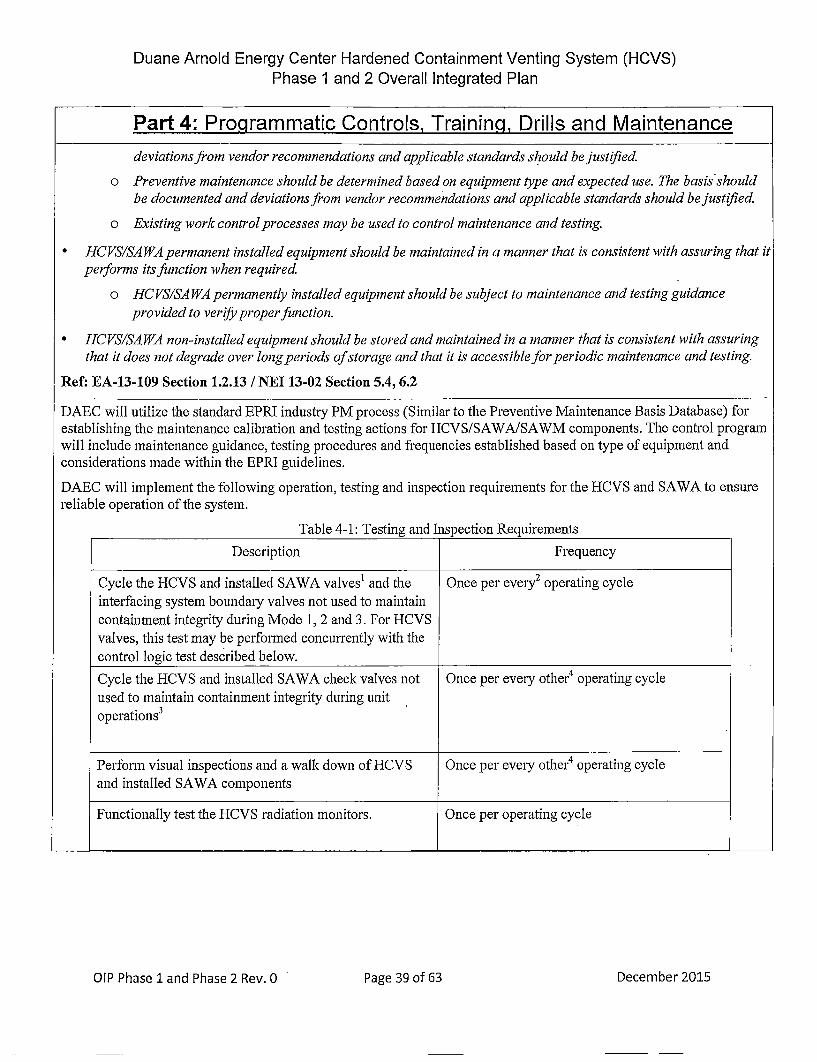
Duane Arnold Energy Center Hardened Containment Venting System (HCVS)Phase 1 and 2 Overall Integrated Plan
Part 4: ProQrammatic& Controls, Trainina. Drills and Maintenancedeviations from vendor recommendations and applicable standards should be justified.
o Preventive maintenance should be determined based on equipment type and expected use. The basis shouldbe documented and deviations from vendor recommendations and applicable standards should be justified.
o Existing work control processes may be used to control maintenance and testing.
* HCVS/SA WA permanent installed equipment should be maintained in a manner that is consistent with assuring that itperforms its function when required.
o HCVS/SA WA permanently installed equipment should be subject to maintenance and testing guidance
provided to verify proper function.
* HCVS/SA WA non-installed equipment should be stored and maintained in a manner that is consistent with assuring
that it does not degrade over long periods of storage and that it is accessible for periodic maintenance and testing.
Ref: EA-13-109 Section 1.2.13 / NET 13-02 Section 5.4, 6.2
DAEC will utilize the standard EPRI industry PM process (Similar to the Preventive Maintenance Basis Database) forestablishing the maintenance calibration and testing actions for HCVS/SAWA/SAWM components. The control programwill include maintenance guidance, testing procedures and frequencies established based on type of equipment andconsiderations made within the EPRI guidelines.
DAEC will implement the following operation, testing and inspection requirements for the IHCVS and SAWA to ensurereliable operation of the system.
Table 4-1: Testing and Inspection Requirements
Description Frequency
Cycle the HCVS and installed SAWA valves' and the Once per evely2 operating cycleinterfacing system boundamy¢ valves not used to maintaincontainment integrity during Mode 1, 2 and 3. For HCVSvalves, this test may be performed concurrently with thecontrol logic test described below.Cycle the HCVS and installed SAWA check valves not Once per evemy• other4 operating cycleused to maintain containment integrity during unitoperations3
Perform visual inspections and a walk down of HCVS Once per every other4 operating cycleand installed SAWA components
Functionally test the HCVS radiation monitors. Once per operating cycle
OIP Phase 1 and Phase 2 Rev. 0Pae3of6Dcmbr21Page 39 of 63 December 2015

Duane Arnold Energy Center Hardened Containment Venting System (HCVS)Phase 1 and 2 Overall Integrated Plan
Part 4: Programmatic Controls, Training, Drills and MaintenanceLeak test the HCVS. 1. Prior to first declaring the system
functional;
2. Once eveiy three operating cyclesthereafter; and
3. After restoration of any breach of systemboundary within thebuildings
Validate the HCVS operating procedures by conducting Once per every other operating cyclean open/close test of the HCVS control function from itscontrol location and ensuring that all HCVS vent pathand interfacing system boundary valves5 move to theirproper (intended) positions.
1 o required for HCVS and SAWA check valves.2 Atrtwo consecutive successful performances, the test frequency may be reduced to a maximum of once per eveiy,
other operating cycle.3 o required if integrity of check function (open and closed) is demonstrated by other plant testing requirements.
4Aertwo consecutive successful performances, the test frequency may be reduced by one operating cycle to a maximumof once per every fourth operating cycle.5 Interfacing system boundary valves that are normally closed and fail closed under ELAP conditions (loss of powerand/or air) do not require control function testing under this part. Performing existing plant design basis function testingor system operation that reposition the valve(s) to the HCVS required position will meet this requirement without the needfor additional testing.
Notes:
OIP Phase 1 and Phase 2 Rev. 0Pge4of6Dcmer21 December 2015

Duane Arnold Energy Center Hardened Containment Venting System (HCVS)Phase 1 and 2 Overall Integrated Plan
Part 5: Milestone ScheduleProvide milestone sch'edule
This schedule should include:
* Modifications timeline* Procedure guidance development complete
o HCVS Actionso Maintenance
* Storage plan (reasonable protection)* Staffing analysis completion* Long term use equipment acquisition timeline* Training completion for the HCVS ActionsThe dates specifically required by the order are obligated or committed dates. Other dates are planned dates subject tochange. Updates will be provided in the periodic (six month) status reports.
Ref: EA-13-109 Section D.1, D.3 / NEI 13-02 Section 7.2.1
The following milestone schedules are provided. The dates are planning dates subject to change as designand implementation details are developed. Any changes to the following target dates will be reflected in thesubsequent 6 month status reports.
Phasee 1 Milestone Schedule:
Milestone Target Activity CommentsCompletion Status {Include date changqes in
Date this column}
Issue preliminarylconceptual design Report Jun, 2014 Complete
Submit Overall Integrated Implementation Plan Jun 2014 Complete
Initial Outage for Phase 1 Planning Nov, 2014 Complete
Submit 6 Month Status Report Dec. 2014 Complete
Submit 6 Month Status Report Jun. 2015 Complete
Submit 6 Month Status Report Dec. 2015 Complete Simultaneous with Phase 2with this OIPsubmittal
Design Complete Phase 1 Mar. 2016 Started
Submit 6 Month Status Report Jun. 2016 Not Started This status report willinclude both Phase 1 and 2scope.
Operations Procedure Changes Developed Oct. 2016 Not Started
Site Specific Maintenance and Testing Procedures Developed Oct. 2016" Not Started
Training Complete Oct. 2016 Not Started
Implementation Outage End of Not StartedRFO25
OIP Phase 12 and Phase 2 Rev. 0Pae4of6Dcmbr21 December 2015

Duane Arnold Energy Center Hardened Containment Venting System (HCVS)Phase 1 and 2 Overall Integrated Plan
Part 5: Milestone ScheduleProcedure Changes Active End of Not Started
RFO25
Walk Through Demonstration/Functional Test End of Not StartedRFO25
Submit Completion Report 60 days after Not StartedRFO25
.: e 2-7 • . .• . ',v .,,. .'•- °,: .: ' ! *• . -' .: ,.> . '. •3 " " • : .. •, ''d • • : " • •,":.' '',<:•- -•;< ' ' -i ' .•,•, '% ." •;;
Phase 2 Milestone Schedule
Milestone Target Activity CommentsCompletion Status {lnclude date changes in
Date this column}
Submit Overall Integrated Implementation Plan Dec 201.5 Complete Simultaneous with Phase 1
with this OIPsubmittal
Hold preliminary/conceptual design meeting June 2016
Submit 6 Month Status Report June 2016 This status report willinclude both Phase 1 and 2scope.
Submit 6 Month Status Report Dec 2016
Submit 6 Month Status Report June 2017
Design Engineering On-site/Complete Jan 2018
Submit 6 Month Status Report Dec 2017
Submit 6 Month Status Report June 2017
Operations Procedure Changes Developed Oct 2018
Site Specific Maintenance Procedure Developed Oct 2018
Training Complete Oct 2018
Implementation Outage RFO 26
Procedure Changes Active RFO26
Walk Through Demonstration/Functional Test RFO 26
Submit Completion Report RFO 26
Notes:
OIP PhaselIand Phase 2Rev.0 Pae40f6 eebr21Page 42 of 63 December 2015

Duane Arnold Energy Center Hardened Containment Venting System (HCVS)Phase 1 and 2 Overall Integrated Plan
Attachment 1: HCVSISAWA Portable Equipment
BDBEE Severe Performance Maintenance / PM requirementsList portable equipment Venting Accident Criteria
____ ___ ____ ___ ____ ___ ____ ___ ___Venting
Nitrogen Cylinders X X Required Check periodically for pressure,volume is 11 replace or replenish as neededbottlesassumingreplenishmentafter first 24hours usingestimatednumber ofvalve openingsand purge ofvent line
FLEX DG (and associated equipment) X X TBD Per Response to EA-12-049
FLEX (SAWA) Pump (and associated equipment) X X 272 gpm for Per Response to EA-1 3-1 09
first 4 hoursand 55 gpmfor thesustainedoperating
______________________________________________ _________period ___________________
OIP Phase 1land Phase 2 Rev. 0Pae3of6Dcmbr21 December 2015
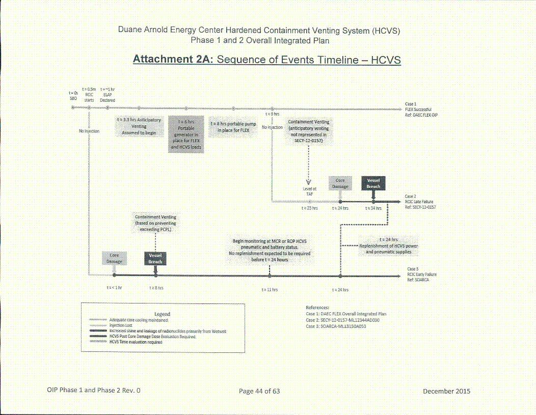
Duane Arnold Energy Center Hardened Containment Venting System (HCVS)Phase 1 and 2 Overall Integrated Plan
Attachment 2A: Seqiuence of Events Timeline - HCVS
t~a3m t=~1hrRCIC ClAP
starts Dedare~
lnjet~
t 9 hrst h3.3hrs Artipatory
Verntin tsflhrsportablepump Nin place forfLEX
______FW( SuccessfuRef: OAEC FLEX OiP
Contairnment Venting(antipatory vetignot reprsetd in
SECY-12-0157]
Containment venting(based on preventing
exceein PCPL)
Levelat ......
TAF £ ase 2• ,,, ROC2 Late Failure
* St•24hirs-.... Replenishment of lICVS power
iuired and pneumatic suppliesCore
Damage
Begin monitoring• at MCR or ROP HIpneumatic and battery sttus.
No replenishment expected to be re•beforet = 24 hours
p p ReF: SOARcA
t 81st r~ Sit hrt I 24 hrt
Legen~d...-.....Adequate core maoir Bntainsd
1 IiV Post Core Danage Dosre EwvalJo qireX CVS en evam ,luation requred
References:Cae 1: DAte FLEX Overall Integrated PlanCase 2: SECY-I2-GI57-MLI2344A[D03OCase 3: SOARCA-ML1315OAO53
OIP Phase 1 and Phase 2 Rev. 0Pae4of3Dembr21 Page 44 of 63 December 2015
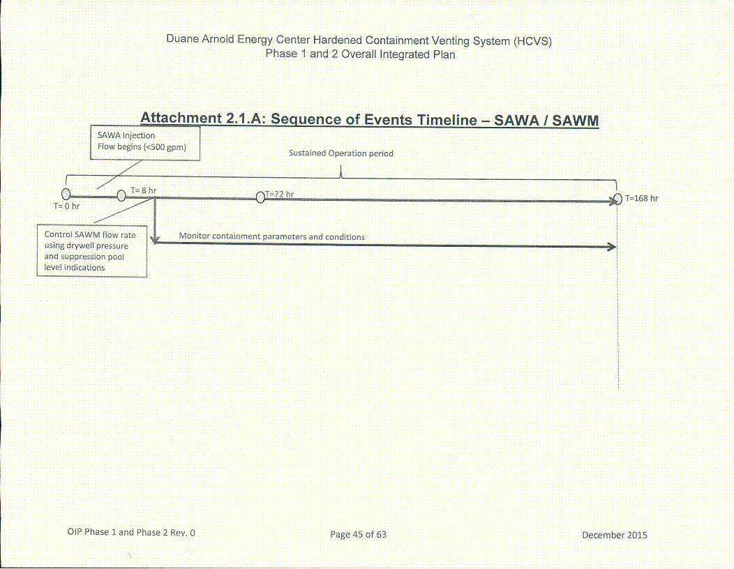
Duane Arnold Energy Center Hardened Containment Venting System (HCVS)Phase 1 and 2 Overall Integrated Plan
achment 2.1 .A: Sequence of Events Timeline - SAWA I SAWM
I) gpm) Sustained Operation period
('•T=72 hr • T=168 hr
alP Phase 1 and Phase 2 Rev. 0Pge4of6Dcmbr21

Duane Arnold Energy Center Hardened Containment Venting System (HCVS)Phase 1 and 2 Overall Integrated Plan
Attachment 2.1.B: Seqiuence of Events Timeline - SADV
N/A
OIP Phase 1 and Phase 2 Rev. O ae4 f6 eebr21December 2015

Duane Arnold Energy Center Hardened Containment Venting System (HCVS)Phase 1 and 2 Overall Integrated Plan
Attachment 2.1 .C: SAWA / SAWM Plant-Specific Datum
Wetwell WR Level instrument range= 0'- 98'
Wetwell vent Torus Free Volume= 1,163,663 gal
p. -q p.-
Additional freeboardheight= 9'- 3"
f•
7
Sloerheight = 1 '- 3 3/4'Drywell floor
vel
Freeboard height= S'- 7"(303,000 gal)
Max. Normal Wetwell-Level =10'- 5" (460,020
.................................. I
Wetwell NR Level instrument:range= 1.5'-16' (763,020 gal) / I
I gal)
Wetwell bottom height = 0'
NOTES:1. Narrow Range Torus Level Indicator Range is 1.5' - 16'. Wide Range
Level Indicator range is 0'- 98'.2. The maximum expected SAWA water level (23') is a conservative
calculation based on water addition only. This does not reflect anymass loss due to venting. This is intended to provide a conservativeand bounding torus water level.
3. SAWA injection flowrates are 272 gpm for 4 hours and 55 gpm for thesustained operating period (7 days). Based on these flowrates, the toruslevel is expected to change as follows:
* Flowrate of 272 gpm results in a rate of rise of approx.
0.285 fl/hr.* Flowrate of 55 gpm results in a rate of rise of approx. 0.058
ft/hr.4. Calculated volumes are preliminary, and will be validated by analysis.
December 2015OIP Phase 1 and Phase 2 Rev. 0Pae7of6

Duane Arnold Energy Center Hardened Containment Venting System (HCVS)Phase 1 and 2 Overall Integrated Plan
Attachment 2.1.D: SAWM SAMG Approved LancquacqeThe following general cautions, priorities and methods will be evaluated for plant specific applicability andincorporated as appropriate into the plant specific SAMGs using administrative procedures for EPG/SAG changecontrol process and implementation. SAMGs are symptom based guidelines and therefore address a wide variety ofpossible plant conditions and capabilities while these changes are intended to accommodate those specificconditions assumed in Order EA-13-109. The changes will be made in a way that maintains the use of SAMGs in asymptom based mode while at the same time addressing those conditions that may exist under extended loss of ACpower (ELAP) conditions with significant core damage including ex-vessel core debris.
Actual Approved Language that will be incorporated into site SAMG*Cautions:* Addressing the possible plant response associated with adding water to hot core debris and the resulting
pressurization of the primary containment by rapid steam generation.* Addressing the plant impact that raising suppression pool water level above the elevation of the suppression
chamber vent opening elevation will flood the suppression chamber vent path.Priorities:With significant core damage and RPV breach, SAMGs prioritize the preservation of primary containment integritywhile limiting radioactivity releases as follows:
* Core debris in the primary containment is stabilized by water addition (SAWA)* Primary containment pressure is controlled below the Primary Containment Pressure Limit (Wetwell venting)* Water addition is managed to preserve the Mark 1/Il suppression chamber vent paths, thereby retaining the
benefits of suppression pool scrubbing and minimizing the likelihood of radioactivity and hydrogen release into thesecondary containment (SAWM)
Methods:Identify systems and capabilities to add water to the RPV or drywell, with the following generic guidance:
• Use controlled injection if possible.* Inject into the RPV if possible.• Maintain injection from external sources of water as low as possible to preserve suppression chamber vent
capability.* Actual language may vary by acceptable site procedure standards, but intent and structure should follow this guidance.
OIP Phase 1 and Phase 2 Rev. 0Pae4of6Dcmbr21 December 2015

Duane Arnold Energy Center Hardened Containment Venting System (HCVS)Phase 1 and 2 Overall Integrated Plan
Attachment 3: Conceptual Sketches(Conceptual sketches, as necessary to indicate equipment which is installed or equipment hookups necessary for the HCVSActions)
Sketch 1: Electrical Layout of System (preliminary)
* Instrumentation Process Flow* Electrical Connections
Sketch 2: P&ID Layout of WW Vent (preliminary)
* Piping routing for vent path - VWVV Vent* Demarcate the valves (in the vent piping) between the currently existing and new ones• WW Vent Instrumentation Process Flow Diagram* Egress and Ingress Pathways to ROS, Battery Transfer Switch, DG Connections and Deployment location• Site layout sketch to show location/routing of WW vent piping and associated components. This should include
relative locations both horizontally and vertically
Sketch 3: P&ID Layout of SAWA (preliminary)
*Piping routing for SAWA path• SAWA instrumentation process paths• SAWA connections* Include a piping and instrumentation diagram of the vent system. Demarcate the valves (in the vent piping) between
the currently existing and new ones.* Ingress and egress paths to and from control locations and manual action locations* Site layout sketch to show locations of piping and associated components. This should include relative locations
both horizontally and vertically
OIP Phase 1land Phase 2 Rev. 0Pae4of6Dcmbr21 December 2015
Duane Arnold Energy Center Hardened Containment Venting System (HCVS)Phase 1 and 2 Overall Integrated Plan
4BOVAC IrndCcntRr
153
FLE~( 490 ~AC
Generator
SAWA
FLEX 120 VACPortatjkŽ
Gener~tOr~
Sketch 1: Electrical Layout of SystemReferences:
EC 281991, HCVS Modification
EC 280490, FLEX Electrical Modification
alP Phase 1 and Phase 2 Rev. 0Pae5of6Dcmbr21 Page 50 of 63 December 2015

Duane Arnold Energy Center Hardened Containment Venting System (HCVS)Phase 1 and 2 Overall Integrated Plan
YD4T TO ATp~R~
BECH-M143<1>
Reference EC 281991, HCVSModification
Sketch 2a: Layout of Planned HCVS
OIP Phase 1 and Phase 2 Rev. 0Pae5of6Dcmbr21Page 51 of 63 December 2015
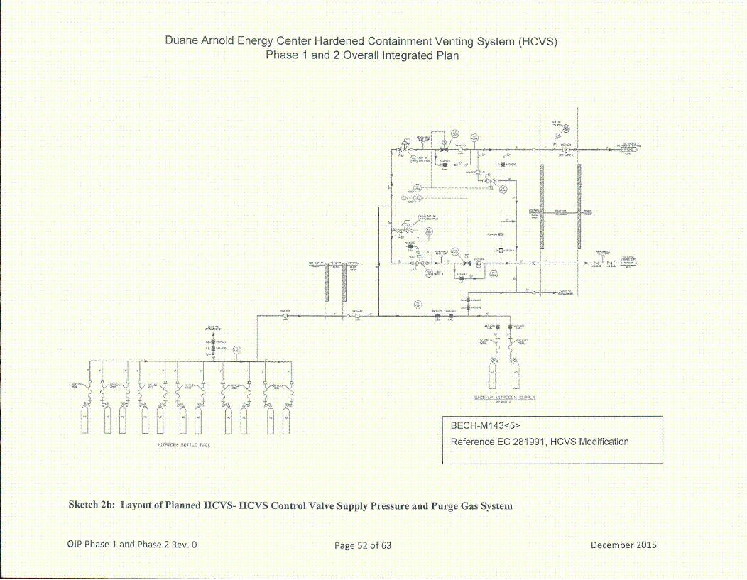
Duane Arnold Energy Center Hardened Containment Venting System (HCVS)Phase 1 and 2 Overall Integrated Plan
'9',
p p
A
'I 'I ~I I I I It ~N -'
qr~ >tjjU iLi BECH-M143<5>
Reference EC 281991, HCVS Modification
Sketch 2b: Layout of Planned HCVS- HCVS Control Valve Supply Pressure and Purge Gas System
OIP Phase 1land Phase 2 Rev. 0Pae2of3Dcmbr01 December 2015
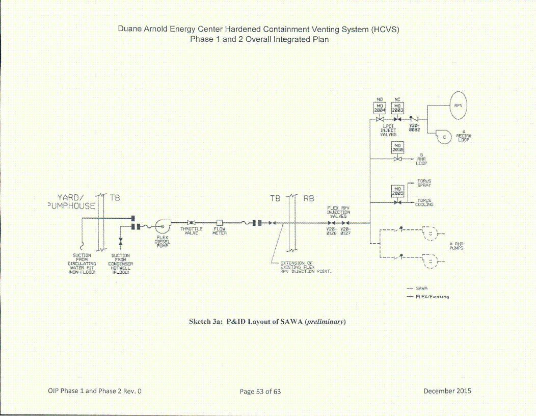
Duane Arnold Energy Center Hardened Containment Venting System (HCVS)Phase 1 and 2 Overall Integrated Plan
PECIPILOCP
RSL~O0
TZPRAY
Y~RfD/WMPHGUSE
SUCTIONFR H
CIRCWATINQWATER PIT
tNON-FLOOD~
A TB
FLEX AE MEE
DIESEL
UC TEONFROM
CONOENSERH TWELL
TB RBFLEX RPV~XJECT1ON
V~LVES
V21t- V 0'-•fl26 I2I7
-- 4 • RHRI PUMPS
E~TEN'~1O~ UF2xJUTI~2 FLEXF~P~ Ir~JECTW'~ POINT.
- FLEX/E~isvir~
Sketch 3a: P&ID Layout of SAWA (preliminary)
OIP Phase 1land Phase 2 Rev. 0Pae5of6Dcmbr21 December 2015
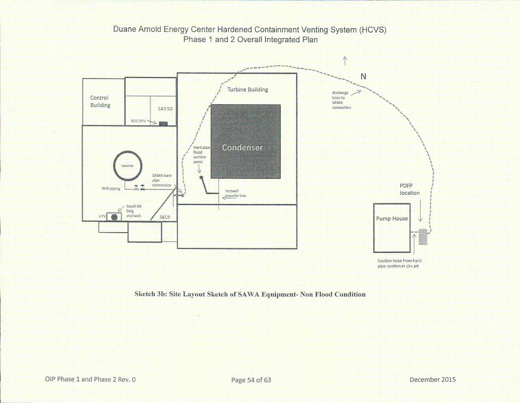
Duane Arnold Energy Center Hardened Containment Venting System (HCVS)Phase 1 and 2 Overall Integrated Plan
,I
ffine Building discharge •d•%,
hose to N'
SAWA• I• connection
I/
/I
I
/# H-ard pipe
•'floodSUCtion
point
a a- -
N
I HotwellI-ne
\
PDFPloa io
Pup ouse}1
Suction hose from hardpipe suction in circ pit
Sketch 3b: Site Layout Sketch of SAWA Equipment- Non Flood Condition
OIP Phase 1 and Phase 2 Rev. 0Pae5of6Dcmbr21 December 2015

Duane Arnold Energy Center Hardened Containment Venting System (HCVS)Phase 1 and 2 Overall Integrated Plan
IN
Turbine Building
ControlBuilding
1A3 SG
ROS HPV -
Hard pipeflood suctionpoint •
Hotwell•transfer line
- -
I- -
Suction hose fromheater bay
PDFP positionduring Flood
I
Sketch 3c: Site Layout Sketch of SAWA Equipment- Flood Condition
OIP Phase 1 and Phase 2 Rev. 0Pae5of3Dcmbr21 Page 55 of 63 December 2015
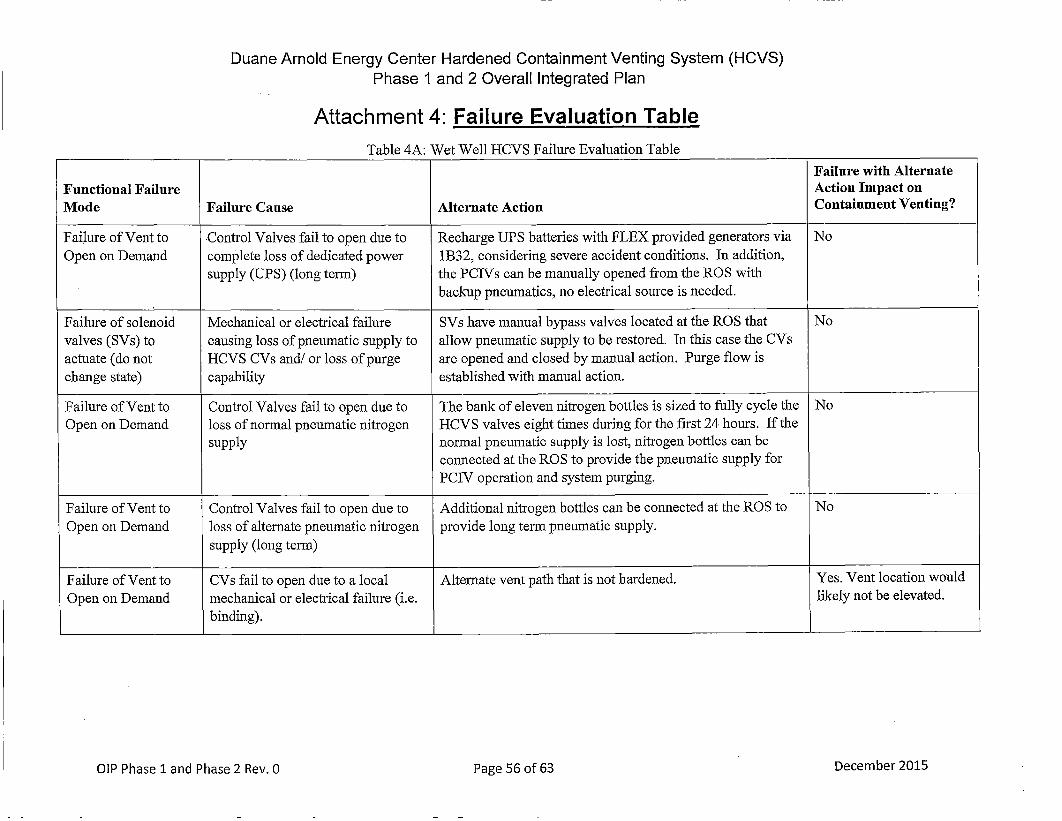
Duane Arnold Energy Center Hardened Containment Venting System (HCVS)Phase 1 and 2 Overall Integrated Plan
Attachment 4: Failure Evaluation Table
Table 4A: Wet Well HCVS Failure Evaluation TableFailure with Alternate
Functional Failure Action Impact onMode Failure Cause Alternate Action Containment Venting?
Failure of Vent to Control Valves fail to open due to Recharge UPS batteries with FLEX provided generators via NoOpen on Demand complete loss of dedicated power 1B32, considering severe accident conditions. In addition,
supply (UPS) (long term) the PCIVs can be manually opened from the ROS withbackup pneumatics, no electrical source is needed.
Failure of solenoid Mechanical or electrical failure SVs have manual bypass valves located at the ROS that Novalves (SVs) to causing loss of pneumatic supply to allow pneumatic supply to be restored. In this case the CVsactuate (do not HCVS CVs and!/or loss of purge are opened and closed by manual action. Purge flow ischange state) capability established with manual action.
Failure of Vent to Control Valves fail to open due to The bank of eleven nitrogen bottles is sized to fully cycle the NoOpen on Demand loss of normal pneumatic nitrogen HCVS valves eight times during for the first 24 hours. If the
supply normal pneumatic supply is lost, nitrogen bottles can beconnected at the ROS to provide the pneumatic supply forPCIV operation and system purging.
Failure of Vent to Control Valves fail to open due to Additional nitrogen bottles can be connected at the ROS to NoOpen on Demand loss of alternate pneumatic nitrogen provide long termn pneumatic supply.
supply (long term)
Failure of Vent to CVs fail to open due to a local Alternate vent path that is not hardened. Yes. Vent location wouldOpen on Demand mechanical or electrical failure (i.e. likely not be elevated.
binding).
OIP Phase 1land Phase 2 Rev. 0Pae6of3Dcmbr21 December 2015

Duane Arnold Energy Center Hardened Containment Venting System (HCVS)Phase 1 and 2 Overall Integrated Plan
Attachment 5: References1. Generic Letter 89-16, Installation of a Hardened Wetwell Vent, dated
September 1, 1989
2. Order EA-12-049, Mitigation Strategies for Beyond-Design-Basis ExternalEvents, dated March 12, 2012
3. Order EA-12-050, Reliable Hardened Containment Vents, dated March 12,2012
4. Order EA-12-051, Reliable SFP Level Instrumentation, dated March 12,2012
5. Order EA-1 3-1 09, Severe Accident Reliable Hardened Containment Vents,dated June 6, 2013
6. JLD-ISG-2012-01, Compliance with Order EA-12-049, MitigationStrategies for Beyond-Design-Basis External Events, dated August 29,2012
7. JLD-ISG-2012-02, Compliance with Order EA-12-050, Reliable HardenedContainment Vents, dated August 29, 2012
8. JLD-ISG-2013-02, Compliance with Order EA-1 3-1 09, Severe AccidentReliable Hardened Containment Vents, dated November 14, 2013•
9. NRC Responses to Public Comments, Japan Lessons-Learned ProjectDirectorate Interim Staff Guidance J LD-ISG-2012-02: Compliance with Order EA-12-050, Order Modifying Licenses with Regard to Reliable HardenedContainment Vents, ADAMS Accession No. ML12229A477, dated August 29,2012
10. NEI 12-06, Diverse and Flexible Coping Strategies (FLEX) ImplementationGuide, Revision 0, dated August 2012
11. NEI 13-02, Industry Guidance for Compliance with Order EA-1 3-109,Revision 1, Dated April 2015
12. NEI 13-06, Enhancements to Emergency Response Capabilities forBeyond Design Basis Accidents and Events, Revision 0, dated March2014
13. NEI 14-01, Emergency Response Procedures and Guidelines for ExtremeEvents and Severe Accidents, Revision 0, dated March 2014
14. NEI HCVS-FAQ-01, HCVS Primary Controls and Alternate Controls andMonitoring Locations
15. NEI HCVS-FAQ-02, HCVS Dedicated Equipment
16. NEJ HCVS-FAQ-03, HCVS Alternate Control Operating Mechanisms
OIP Phase 1land Phase 2 Rev. 1 Pg 7o 3Spebr2,21Page 57 of 63

Duane Arnold Energy Center Hardened Containment Venting System (HCVS)Phase 1 and 2 Overall Integrated Plan
17. NEI HCVS-FAQ-04, HCVS Release Point
18. NEI HCVS-FAQ-05, HCVS Control and 'Boundary Valves'
19. NEI HCVS-FAQ-06, FLEX Assumptions/HCVS Generic Assumptions
20. NEI HCVS-FAQ-07, Consideration of Release from Spent Fuel PoolAnomalies
21 . NEI HCVS-FAQ-08, HCVS Instrument Qualifications
22. NEI HCVS-FAQ-09, Use of Toolbox Actions for Personnel
23. NEI White Pap3er HCVS-WP-01, HCVS Dedicated Power and Motive Force
24. NEI White Pap3er HCVS-WP-02, HCVS Cyclic Operations Approach
25. NEI White Pap3er HCVS-WP-03, Hydrogen/CO Control Measures
26. NEI White Pap3er HCVS-WP-04, Missile Evaluation for HCVS Components30 Feet Above Grade
27. IEEE Standard 344-2004, IEEE Recommended Practice for SeismicQualification of Class I1E Equipment for Nuclear Power GeneratingStations,
28. DAEC EA-12-049 (FLEX) Overall Integrated Implementation Plan, Rev 0,February 2013
29. DAEC EA-12-050 (HCVS) Overall Integrated Implementation Plan, Rev 0,February 2013
30. DAEC EA-12-051 (SFPLI) Overall Integrated Implementation Plan, Rev 0,February 2013
31. JLD-ISG-2015-01, Compliance with Phase 2 of Order EA-13-1 09, OrderModifying Licenses with Regard to Reliable Hardened Containment VentsCapable of Operation under Severe Accident Conditions, dated March2015
32. Consideration of Additional Requirements for Containment VentingSystems for Boiling Water Reactors with Mark I and Mark II Containments,SECY-12-0157, ML12344A030
33. NUREG/CR-71 10, VI, R1, State-of-the-Art Reactor ConsequenceAnalyses (SOARCA) Project: Peach Bottom Integrated Analysis,ML1 31 50A053
34. NEI HCVS-FAQ-10, Severe Accident Multiple Unit Response
35. NEI HCVS-FAQ-1 1, Plant Response During a Severe Accident
36. NEI HCVS-FAQ-12, Radiological Evaluations on Plant Actions Prior toHCVS Initial Use
O[P Phase 1 and Phase 2 Rev. 1 ae5 f6 epebr2,21Page 58 of 63
Duane Arnold Energy Center Hardened Containment Venting System (HCVS)Phase I and 2 Overall Integrated Plan
37. NEI HCVS-FAQ-13, Severe Accident Venting Actions Validation
38. NRC Endorsement of "Hardened Containment Venting System (HCVS)Phase 1 and 2 Overall Integrated Plan Template," Revision 1, datedSeptember 22, 2015, and Frequently Asked Questions (FAQs) 10, 11, 12,and 13 (ADAMS Accession No. ML15273A141), dated October 8, 2015
OIP Phase 1land Phase 2 Rev. 1 Pg 9o 3Spebr2,21Page 59 of 63

Duane Arnold Energy Center Hardened Containment Venting System (HCVS)Phase 1 and 2 Overall Integrated Plan
Attachment 6: ChancqeslUpdates to this Overall Integqrated Implementation Plan
This Overall Integrated Plan has been updated in format and content to encompass both PhaseI and Phase 2 of Order EA-I 3-1 09. Any significant changes to this plan will becommunicated to the NRC staff in the 6 Month Status Reports.
OIP Phase l and Phase 2 Rev. 1 ae6 f6 epebr2,21
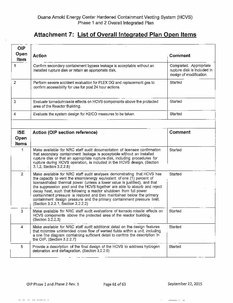
Duane Arnold Energy Center Hardened Containment Venting System (HCVS)Phase 1 and 2 Overall Integrated Plan
Attachment 7: List of Overall Integrated Plan Open Items
OIPOpen Action CommentItem1Confirm secondary containment bypass leakage is acceptable without an Completed. Appropriate
installed rupture disk or retain an appropriate disk. rupture disk is included indesign of modification.
2 Perform severe accident evaluation for FLEX DG and replacement gas to Startedconfirm accessibility for use for post 24 hour actions.
3 Evaluate tornado/missile effects on HCVS components above the protected Startedarea of the Reactor Building.
4 Evaluate the system design for H2/CO measures to be taken. Started
ISE Action (OIP section reference) CommentOpenItems
1 Make available for NRC staff audit documentation of licensee confirmation Startedthat secondary containment leakage is acceptable without an installedrupture disk or that an appropriate rupture disk, including procedures forrupture during HCVS operation, is included in the HCVS design. (Section3.1.2, Section 3.2.2.8)
2 Make available for NRC staff audit analyses demonstrating that HCVS has Startedthe capacity to vent the steam/energy equivalent of one (1) percent oflicensed/rated thermal power (unless a lower value is justified), and thatthe suppression pooi and the HCVS together are able to absorb and rejectdecay heat, such that following a reactor shutdown from full powercontainment pressure is restored and then maintained below the primarycontainment design pressure and the primary containment pressure limit.(Section 3.2.2.1, Section 3.2.2.2)
3 Make available for NRC staff audit evaluations of tornado missile effects on StartedHCVS components above the protected area of the reactor building.(Section 3.2.2.3)
4 Make available for NRC staff audit additional detail on the design features Startedthat minimize unintended cross flow of vented fluids within a unit, includinga one line diagram containing sufficient detail to confirm the description inthe OlP. (Section 3.2.2.7)
5 Provide a description of the final design of the HCVS to address hydrogen Starteddetonation and deflagration. (Section 3.2.2.6)
OIP Phase 1land Phase 2 Rev. 1 Pg 1o 3Spebr2,21Page 61 of 63

Duane Arnold Energy Center Hardened Containment Venting System (HCVS)Phase 1 and 2 Overall Integrated Plan
6 Provide a description of the strategies for hydrogen control that minimizes Startedthe potential for hydrogen gas migration and ingress into the reactorbuilding or other buildings. (Section 3.2.2.6)
7 Make available for NRC staff audit documentation that demonstrates Not Startedadequate communication between the remote HCVS operation locationsand HCVS decision makers during ELAP and severe accident conditions.(Section 3.2.2.5)
8 Make available for NRC staff audit an evaluation of temperature and Startedradiological conditions to ensure that operating personnel can safely accessand operate controls and support equipment. (Section 3.2.1, Section 3.2.2.3,Section 3.2.2..4, Section 3.2.2.5, Section 3.2.2.10, Section 3.2.4.1, Section3.2.4.2, Section 3.2.5.2 and Section 3.2.6)
9 Make available for NRC staff audit the final sizing evaluation for HCVS Startedbatteries/battery charger including incorporation into FLEX DG loadingcalculation. (Section 3.2.2.4, Section 3.2.3.1, Section 3.2.3.2, Section 3.2.4.1,Section 3.2.4.2, Section 3.2.5.1 and Section 3.2.5.2)
10 Make available for NRC staff audit the final sizing evaluation for pneumatic StartedN2 supply. (Section 3.2.2.4, Section 3.2.3.1, Section 3.2.3.2, Section 3.2.4.1,Section 3.2.4.2, Section 3.2.5.1 and Section 3.2.5.2)
11 Make available for NRC staff audit documentation of an evaluation Eliminatedverifying the existing containment isolation valves, relied upon for the As stated in NG-15-0169,HCVS, will open under the maximum expected differential pressure during Six Month Status Update,BDBEE and severe accident wetwell venting. (Section 3.2.2.9) due to design changes in
vent location and routing,existing containmentisolation valves will nolonger be used forventing. New vent designwill utilize a spare toruspenetration with two newprimary containmentisolation valves and arupture disk.An evaluation will be doneto ensure the two newcontainment isolationvalves will open under themaximum expecteddifferential pressureduring BDBEE and severeaccident wetwell venting.
12 Make available for NRC staff audit descriptions of all instrumentation and Startedcontrols (existing and planned) necessary to implement this orderincluding qualification methods. (Section 3.2.2.10)
13 Make available for NRC staff audit the descriptions of local conditions Started(temperature, radiation and humidity) anticipated during ELAP and severeaccident for the components (valves, instrumentation, sensors,
OIP Phase 1. and Phase 2 Rev. 1 Pg 2o 3Spebr2,21Page 62 of 63

Duane Arnold Energy Center Hardened Containment Venting System (HCVS)Phase I and 2 Overall Integrated Plan
transmitters, indicators, electronics, control devices, and etc.) required forHCVS venting including confirmation that the components are capable ofperforming their functions during ELAP and severe accident conditions.(Section 3.2.2.3, Section 3.2.2.5, Section 3.2.2.9, Section 3.2.2.10)
-I- F
14 Provide a justification for deviating from the instrumentation seismicqualification guidance specified in NEI 13-02, endorsed, in part, by JLD-ISG-2013-02 as an acceptable means for implementing applicablerequirements of Order EA-1 3-1 09. (Section 3.2.2.9)
EliminatedAs stated in NG-15-0169,Six Month Status Update,the qualification methodused for each HCVSinstrument will be to theIEEE 344-2004 standardor a substantially similarindustrial standard andtherefore will not bedeviating from NE! 13-02or JLD-ISG-201 3-02.
OIP Phase 1 and Phase 2 Rev. 1 Pg 3o 3Spebr2,21