ductile – brittle transition test programme. purpose and scope. to establish a hounsefield impact...
TRANSCRIPT

DUCTILE – BRITTLE DUCTILE – BRITTLE TRANSITION TEST TRANSITION TEST
PROGRAMMEPROGRAMME

PURPOSE AND SCOPE.PURPOSE AND SCOPE.
To establish a Hounsefield Impact To establish a Hounsefield Impact Machine Test Procedure. Machine Test Procedure.
This procedure will determine the use of This procedure will determine the use of the machine when conducting Ductile-the machine when conducting Ductile-Brittle Transition Tests. Brittle Transition Tests.
The programme will determine safety The programme will determine safety issues related to the test programme. issues related to the test programme.

Hounsefield Impact MachineHounsefield Impact MachineTest ProceduresTest Procedures
1.1. Raise the test-piece pendulum to the lock-in position Raise the test-piece pendulum to the lock-in position to the right of the base.to the right of the base.
2.2. Raise the hammer pendulum to the lock-in position Raise the hammer pendulum to the lock-in position to the left of the base.to the left of the base.
3.3. Set the release mechanism lever to the lock-in Set the release mechanism lever to the lock-in position.position.
4.4. Set the dial to zero on the scale.Set the dial to zero on the scale.5.5. Place the test-piece in the test-piece holder with the Place the test-piece in the test-piece holder with the
notch positioned with the lock-in bar.notch positioned with the lock-in bar.6.6. Release the release mechanism lever to activate the Release the release mechanism lever to activate the
test.test.7.7. Record the energy absorbed in N/m from the scale Record the energy absorbed in N/m from the scale
on the dial.on the dial.8.8. Eject the fractured test-piece and determine the Eject the fractured test-piece and determine the
fracture appearance. fracture appearance. 9.9. Unlock the test machine.Unlock the test machine.

Microsections of received Microsections of received barbar
Carbon SteelCarbon Steel
Lateral viewLateral view
Transverse viewTransverse view
Images to followImages to follow

Heat Treatment of Heat Treatment of received barreceived bar
0.1% Carbon Steel0.1% Carbon Steel Case HardeningCase Hardening
At 930 At 930 ooC C
For 20 minutesFor 20 minutes
Water QuenchedWater Quenched Chemical Chemical
Composition:Composition:
…………....

Microsections of Microsections of Heat Treated Material: 1Heat Treated Material: 1
Normalised @ 900 Normalised @ 900 00c c longitudinal longitudinal x 400x 400
Normalised @ 900 Normalised @ 900 00c c transverse transverse x 400 x 400 edge of sampleedge of sample

Microsections of Microsections of Heat Treated Material: 2Heat Treated Material: 2
Normalised @ 900 Normalised @ 900 00cc
transverse transverse
x 400 x 400
mid T of samplemid T of sample
Normalised @ 900 Normalised @ 900 00cc
transverse transverse
x 400 x 400
centre of samplecentre of sample

Sample PreparationSample Preparation
Impact test pieces Impact test pieces
with Notchwith Notch
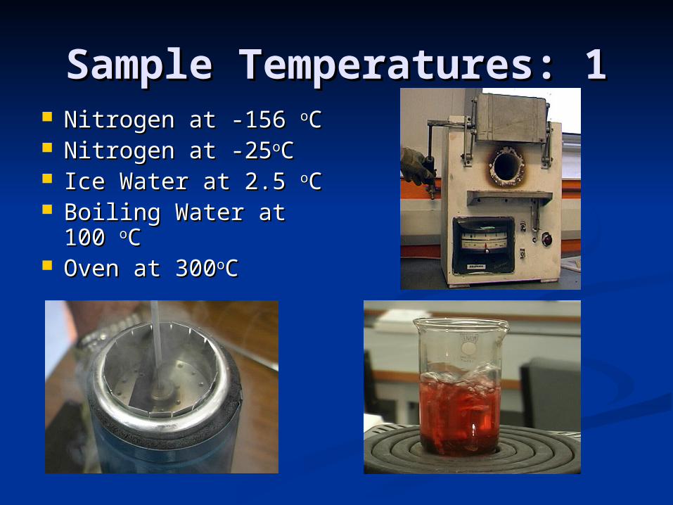
Sample Temperatures: 1Sample Temperatures: 1 Nitrogen at -156 Nitrogen at -156 ooCC Nitrogen at -25Nitrogen at -25ooCC Ice Water at 2.5 Ice Water at 2.5 ooCC Boiling Water at 100 Boiling Water at 100
ooCC Oven at 300Oven at 300ooCC

Sample Temperatures: 2Sample Temperatures: 2
Record Record temperaturetemperature

HandlingHandling
Health and Safety Health and Safety IssuesIssues
Leave at target Leave at target temperature for temperature for
7 minutes7 minutes
Retrieve sample Retrieve sample
using tongsusing tongs

Test Procedure 1Test Procedure 1
Raise the test-piece Raise the test-piece pendulum to the lock-in pendulum to the lock-in position to the right of position to the right of the base.the base.
Raise the hammer Raise the hammer pendulum to the lock-in pendulum to the lock-in position to the left of the position to the left of the base.base.
Set the release Set the release mechanism lever to the mechanism lever to the lock-in position.lock-in position.
Set the dial to zero on Set the dial to zero on the scale.the scale.

Test Procedure 2Test Procedure 2
Place the test-Place the test-piece in the test-piece in the test-piece holder with piece holder with the notch the notch positioned with positioned with the lock-in bar.the lock-in bar.

Test Procedure 3Test Procedure 3
Release the Release the release release mechanism lever mechanism lever to activate the to activate the test.test.

Test Procedure 4Test Procedure 4
Record the Record the energy absorbed energy absorbed in N/m from the in N/m from the scale on the dial.scale on the dial.

Test Procedure 5Test Procedure 5
Eject the fractured Eject the fractured test-piece and test-piece and determine the determine the fracture fracture appearance. appearance.
Unlock the test Unlock the test machine.machine.

ResultsResults
Example of GraphExample of Graph
0
10
20
30
40
50
60
70
80
90
N/ M
Sample 1Sample 2Sample 3

Microsections of Microsections of FractureFracture
Observe micro-Observe micro-photograph.photograph.

ConclusionsConclusions
Compare and Contrast ResultsCompare and Contrast Results
Compare with Predicted ResultsCompare with Predicted Results
OutcomesOutcomes
RecommendationsRecommendations

Test Procedure VideoTest Procedure Video
Impact2.mpg 35 Seconds 5.5 MB MPEG1