dukc® chart overlay - iho 6/twlwg 6-4.3-duk… · - wave response - changes in tidal residual ......
TRANSCRIPT

DUKC® Chart Overlay
Presentation to IHO TWL and DQ Working Groups
Wollongong, March 2014

Outline
• Who is OMC?
• DUKC® description & methodology.
• DUKC® Chart Overlay concept.
• Chart Overlay application example.
• Where to from here...?
• OMC Wish List

Who is OMC International?
• Provide under-keel clearance advice
• Inventor and sole supplier of DUKC®
• Installed at 21 Australian, NZ and EU ports

DUKC Users

What is DUKC®?
• “Decision support system for the planning and monitoring of deep draft vessel movements in shallow waters”.
• Provides under keel clearance and sailing advice: – On-shore, and – On-board
• Used by: – Schedulers / planners – VTS officers – Mariners (pilots & masters) – Regulators

What is DUKC®? An example

Dynamic vs. Static
DATUM
“X” % OF DRAFT
DRAFT
DEPTH
PREDICTED TIDE
“X” MUST ACCOUNT FOR
- WAVE RESPONSE
- CHANGES IN TIDAL RESIDUAL
- SQUAT
- SAFETY ALLOWANCES

DUKC® Methodology
DUKC® Bathymetry
Nodes

predicted tide & currents
predicted waves
predicted wind & pressure
ship in given load state
latest sounded depths
8
ship speed envelopes astronomical tides
DUKC® Methodology
NOTE: Minimum depth anywhere in the DUKC®
“Bathymetry Node”
Minimum Keel Elevation

CHART OVERLAY
DUKC® Chart Overlay
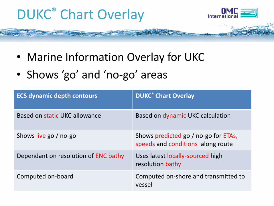
• Marine Information Overlay for UKC
• Shows ‘go’ and ‘no-go’ areas
ECS dynamic depth contours DUKC® Chart Overlay
Based on static UKC allowance Based on dynamic UKC calculation
Shows live go / no-go Shows predicted go / no-go for ETAs, speeds and conditions along route
Dependant on resolution of ENC bathy Uses latest locally-sourced high resolution bathy
Computed on-board Computed on-shore and transmitted to vessel

Computing the 2D overlay
High resolution sounded depths
Minimum depth
10m x 10m overlay grid
DUKC® Bathymetry
Nodes
Compare DUKC® minimum keel elevation to overlay grid
cell depth
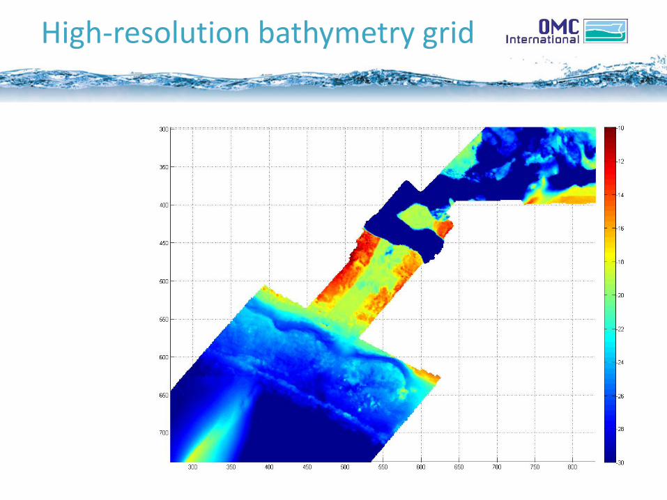
High-resolution bathymetry grid
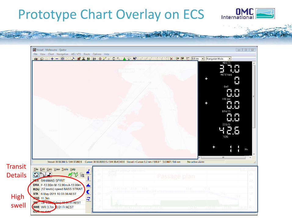
Prototype Chart Overlay on ECS
• High waves / Low waves
High swell
Passage plan
Transit Details

What If – Low Waves...?
• High waves / Low waves
Low swell

Prototype Chart Overlay on ECS
• High waves / Low waves
High swell

Deep-draught transit
• Bahamas Spirit (Tanker)
– LBP 247m, Beam 42m
– Draught 13.9m
Place: Port Phillip Bay Date Taken: 2011-05-06 11:04
Use in Passage Planning
• Forecast effect of departure time and transit speed.
• Hypothetical example in Port of Melbourne.
• Planning a deep draft tanker movement.

What If – 14.7m at 16 knts?

What If – 14.7m at 14 knts?

What If – 14.7m at 12 knts?

Early implementation
• Initial integration with QPS’ Qastor ECS.
• Qastor used by pilots at Melbourne and Port Hedland.
• Integration not exclusive to Qastor.
• Deployed to Port Hedland December 2013.
• Web map version under delivery to AMSA for Torres Strait by June 2014. On-board trial proposed.

System Architecture
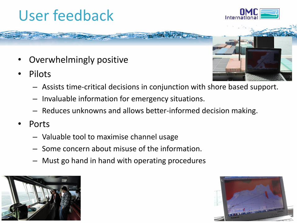
User feedback
• Overwhelmingly positive
• Pilots – Assists time-critical decisions in conjunction with shore based support.
– Invaluable information for emergency situations.
– Reduces unknowns and allows better-informed decision making.
• Ports – Valuable tool to maximise channel usage
– Some concern about misuse of the information.
– Must go hand in hand with operating procedures

WHERE TO FROM HERE?

Where to from here?
• Predictive UKC overlay concept has been proved
• Merge with ongoing e-navigation developments
• Improve integration and robustness
• “Live” UKC?

Relevant standards
• Exchange of:
– Wave and tide (spatial) forecasts.
– Vessel passage plan (and updates).
• High resolution bathymetry data.
• Datum definitions and separation models

E-navigation elements
• Vessel static and loading details.
• Vessel dynamic motion models.
• Ship – shore – ship data communications.
• Integration with ECS or ECDIS display software.

Design decisions
• Which calculations on-board?
• Which calculations on-shore?
• Low bandwidth communications.
• Reliability of results (ensuring accurate, up to date input data).
• Robustness of system to communications or hardware failure.
• Speed / simplicity / useability of the system.
• Degree of coordination required with 3rd party developers.

Outstanding issues
• Custom hardware must be taken on-board (by pilot).
• Display of time dimension on ECS.
• Better integration of passage planning with ECS desirable.
• Transmission and display of space and time varying forecasts.
• Standard approaches to using high resolution bathymetry data.
• Relies on 3G phone coverage for updates.
• Lack of international standard for transmitting UKC data.
• Possible discrepancy between navigational systems.
• Lack of fall-back systems.

What does OMC need? Specifics
• Details on data uncertainty: – total water depth (depth + tide) – Spatial variability (like ZOC)
• Details on vertical datum and datum relations – E.g. CD to WGS84 – Example: Real-time UKC measurement through GPS – Spatial variations
• Details on bathymetry: – Shoal biased? Rounded? – Bed material – Tide reduction method applied (to ensure OMC applies same method) – Ideally can be queried in CD and WGS84 – Ideally an indication of seabed mobility
• Tide data: – Measurement location – Vertical datum of measurement – Relation to WGS84 ellipsoid – At least 2 decimal places… – Has filtering been applied to provided data? – Spatial variation – Astronomical predictions – Tidal streams (observations and predictions)
