dulcoflex peristaltic pump dfda70 - prominentprominent.us/promx/pdf/dfd_70_om.pdf · dulcoflex...
TRANSCRIPT

INSTRUCTIÓN MANUAL DFD70
1
INSTRUCTION MANUAL
DulcoFlex Peristaltic Pump DFDa70 This manual forms an integral part of the pump and must accompany it until its demolition. The peristaltic pump is a machine destined to work in industrial areas and as such the instruction manual must form part of the legislative dispositions and the applicable technical standards and does not substitute any installation standard or eventual additional standard.
The person in charge of safety should therefore guarantee that - The pump is transported, installed, put in service, used, maintained and repaired by qualified personnel who should therefore possess: - Specific training and sufficient experience. - Knowledge of the technical standards and applicable laws. - Knowledge of the general national and local safety standards and also of installation. Any work carried out on the electrical part of the pump should be authorised by the person responsible for safety. Given that the pump is destined to form part of an installation, it is the responsibility of whoever supervises the installation to guarantee absolute safety, adopting the necessary measures of additional protection.
GENERAL SAFETY WARNING
Pumps are machines that due to their functioning under pressure and moving parts can present dangers. - Improper use - Removing the protections and/or disconnecting the protection device - The lack of inspections and maintenance
CAN CAUSE SERIOUS DAMAGE OR INJURY

INSTRUCTIÓN MANUAL DFD70
2
INDEX
Page Nº Cover
01
Index
02
Identification record of equipment
03
Transport, storage and elevation
04
General safety standards
05
General description
07
Installation
08
Roller pressure adjustment
08
Work conditions
08
Performance curves
09
Checks before starting up the machine
10
Maintenance
10
Reposition of the hose – dismantling
11
Reposition of the hose – mounting
11
Problems, causes and solutions
12
Diagram of components parts
13
Spare parts code
14
Certificate of approval
15
Guarantee
16

INSTRUCTIÓN MANUAL DFD70
3
IDENTIFICATION RECORD OF EQUIPMENT
MANUFACTURER:
MODEL OF PUMP: DFD70 SERIAL NUMBER:
DRIVER MARK: DRIVER POWER / SPEED: REDUCER MARK & MODEL:
REDUCTION RATIO:
GEAR REDUCER WITHOUT MOTOR: MECHANICAL VARIATOR + GEAR REDUCER:
GEAR REDUCER WITH ELECTRONIC INVERTER:
WORK SPEED: MAXIMUM SPEED: MINIMUM SPEED:
WORKING MANOMETRIC PRESSURE: MAXIMUM DESIGN PRESSURE: 216 PSI
HOSE MATERIAL: CONNECTIONS MATERIAL:
IMPORTER / SUPPLIER:

INSTRUCTIÓN MANUAL DFD70
4
TRANSPORT, STORAGE and ELEVATION
TRANSPORT
The pump is protected by a wood packaging.
The packaging materials are recyclable. STORAGE
Avoid areas open to inclement weather or excessive humidity.
For storage periods of longer than 60 days, protect the coupling surfaces (clamps, reducers, motors) with adequate anti-oxidant products.
Spare tubes should be stored in a dry place away from direct light. ELEVATION It’s necessary to use elevation belts for the transport and the elevation of the pump. In the
next figure it’s shown the way to use the elevation belts:

INSTRUCTIÓN MANUAL DFD70
5
GENERAL SAFETY STANDARDS
The instructions of this manual, whose inobservance is determined as a failure to meet safety standards, are identified by this symbol
The instructions of this manual, whose inobservance compromises electrical safety, are identified by this simbol.
The instructions of this manual, whose inobservance compromises the correct working of the pump, are identified with this symbol.
Do not start the pump without first having installed the front cover.
For any manipulation of the equipment, it is necessary to make certain that the pump is stopped and the electricity supply disconnected.
Changing the hose should be done with the pump stopped.
Do not exceed the nominal pressure, speed or temperature of the pump, or use the pump for applications other than that originally planned without first consulting the manufacturer or distributor.
WARNING!
WARNING!

INSTRUCTIÓN MANUAL DFD70
6
Cleaning the pipe, including the hose, should be done with fluids compatible with the mentioned drive pump and at its maximum temperature recommended.
Do not start the pump without it being properly secured to the floor.
Do not carry out any maintenance operations or dismantle the pump without first making sure that the pipes are not under pressure and are empty or isolated.
The start system of the motor should be provided with a direction inverter, stop-go button and emergency stop button (together with the pump), in such a way that the pump can be manipulated with total safety.
As the peristaltic pump is volumetric and its functioning is positive displacement, it is necessary to prevent a possible overload of pressure, an example would be the accidental closure of a valve. For this reason it is advisable to fit a safety device such as: a safety valve, pressure limiter, etc. ...
Check the turning direction of the pump, as it is reversible it could generate pressure in the suction and compromise the safety of the installation. The circulation of the fluid should be in the same direction as the turning direction of the pump as seen from the inspection plate situated on the front cover.
The durability of the hose cannot be defined precisely so it is necessary to foresee the possibility of a rupture and subsequent leakage of fluid. If the tube rupture detection probe is fitted (optional part), it can cause the pump to stop or actuate an electric valve.
As the hose having an indeterminate life, and due to the possibility of its
breakage or deterioration, the user is responsible for the prevention of a possible (although most unlikely ) incorporation of breaks from the hose into the product being pumped, once the breakage phase or its deterioration has begun, either by means of filtration or a detection and removal of the possible breaks.
For C.I.P., or S.I.P. process, or similar, it’s necessary to contact with the
manufacturer, because it’s necessary to use a determinate installation, and cleaning conditions.
WARNING!
WARNING!

INSTRUCTIÓN MANUAL DFD70
7
GENERAL DESCRIPTION PERISTALTIC PUMP
Construction of the pump. The outer casing terminates with flanged connections. Inside the casing are found the rotor, completed with two shoes. As this is revolving it compresses the reinforced tube and in this way generates a pumping action. A change in the direction of rotation will give rise to a change in direction of the pumped fluid.
1
2
4
3
INSTALLATION
Installation should normally be made in a well-ventilated area away from heat sources. If it is
necessary to place the pump outside it should be provided with a cover to protect it from sunlight and inclement weather.
The positioning of the pump should allow easy access for all kinds of maintenance operations.
Suction. The pump should be as near as possible to the supply of liquid so that the suction pipe is as short and straight as possible. The suction pipe should be perfectly airtight and made of suitable material so that it does not collapse due to the internal drop in vacuum. The minimum diameter should be similar to that of the tubular element. With viscous fluids a larger diameter is recommendable. (Consult manufacturer or distributor). The pump has positive suction and does not need an inlet valve. The pump is reversible, and so the suction connection can be either one of the two available connections. (Normally the one which adapts itself physically better to the installation would be chosen). It is recommendable to use a flexible connection between the piping and the collars of the pump in order to avoid the transmission of vibration to the piping.
Impulsion. To reduce power being absorbed, use the straightest and shortest piping possible. The diameter should be the same as the nominal diameter of the pump, excepting precise calculations of load losses. With viscous fluids a bigger diameter is needed. (Consult the manufacturer or distributor). Connecting the fixed piping to the pump with a length of flexible pipe facilitates maintenance and avoids vibrations and loads on the pump. Fix the piping firmly. The discharge will pulsate: To avoid such effect, it is advisable to install adequate pulsation dampeners. (See accessories.)

INSTRUCTIÓN MANUAL DFD70
8
PRESSURE ADJUSTMENT
The peristaltic pump, includes a shims (Figure 7 ), that are used to adjust the exact pressing distance of the shoe ( figure 5 ).
5
7
4
The shims are installed from factory to work at the work conditions indicated ( in function of the speed and the work pressure), and following the next tables:
DULCO Flex 15/16000
Rpm 0-19 20-39 40-59 60-79 80-99
PSI
7.25 3 2 1 0 0
36.25 4 3 2 1 --
72.5 6 5 4 3 --
108.75 7 6 5 -- --
145 9 8 7 -- --
181.25 10 9 8 -- --
217.5 12 11 -- -- --
WORK CONDITIONS
There are a limits of temperatures and pressures, in function of the hose selected. Those limits are the next:
MATERIAL TEMPERATURE MIN. (ºF)
TEMPERATURE MAX. (ºF)
AMBIENT TEMPERATURE MIN. (ºF)
PRESSURE MAX. (PSI)
NR -4 176 -40 217.5
NBR 14 176 -40 217.5
EPDM 14 176 -40 217.5
NR-A 14 176 -40 217.5
NBR-A 14 176 -40 217.5
INSTRUCTIÓN MANUAL DFD70
9
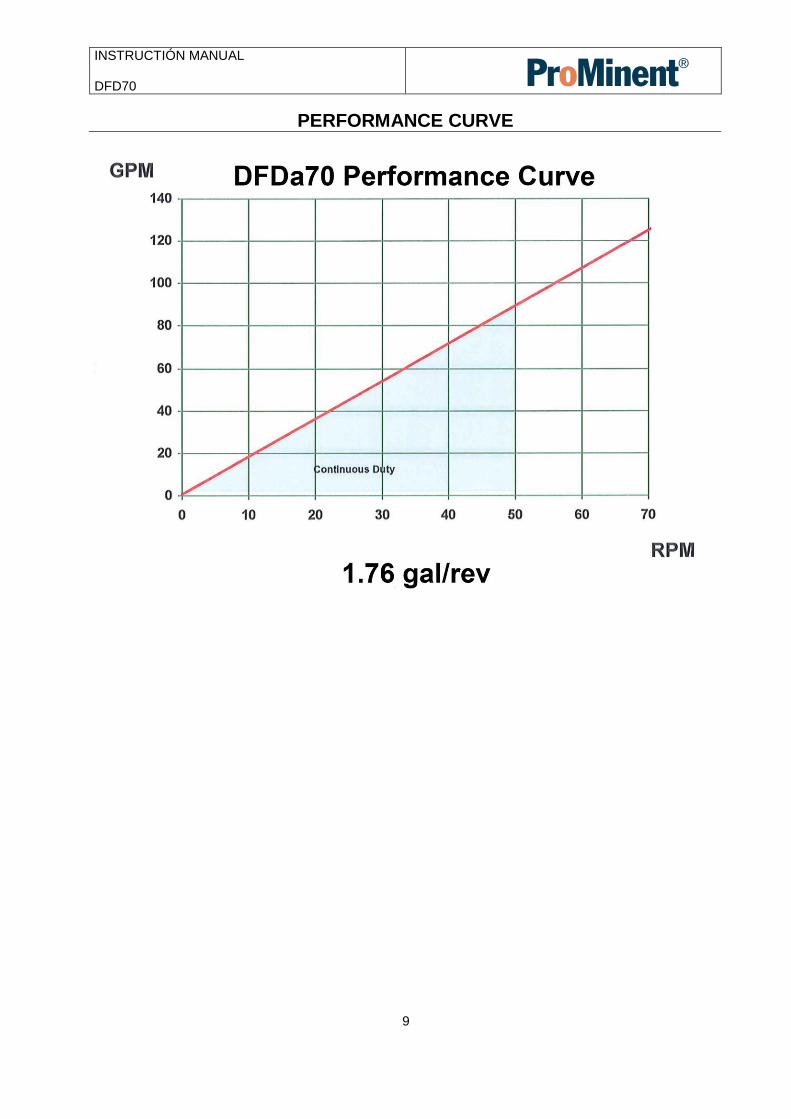
PERFORMANCE CURVE

INSTRUCTIÓN MANUAL DFD70
10
CHECKS BEFORE SWITCHING ON THE PUMP
Check that the pumping equipment has not suffered any damage during transportation or storage, any damage should be notified to the supplier immediately. Check that the network voltage is suitable for the motor. Make sure that the hose is suitable for the fluid to be pumped and that it will not be chemically affected, check also that the temperature of the fluid does not exceed that recommended. Lubrication. Check that the level of the lubricant in the casing of the pump is correct.(DFD70 = 25 liters) The specially formulated DulcoLube lubricant can be obtained from the authorized distributor. The use of the aforementioned lubricant ensures a longer life of the pipe. Check that the protectors of the moving parts are correctly assembled.
Check that the thermal protector corresponds with that of the values on the plate on the motor.
Check that the direction of rotation is correct. (Rotation test). Check that the optional electrical components are connected to the control panel and test that they function correctly. In cases of doubt of the valuation of discharge pressure (e.g. high viscosity), mount a pressure gauge on the discharge. Check in predicted working conditions that the values of flow, pressure and absorbed power of the motor correspond to the project.
MAINTENANCE
Any work carried out on the pump must be done when the pump is stationary and disconnected from the electricity supply.
Lubrication. Check that the lubricant level is correct. The correct level is shown on the lower inspection cover installed on the front cover of the body of the pump. Add lubricant as necessary. Check that the lubricant level in the gear reducer and/or the variator are correct and carry out periodic changes of lubricant according to the maintenance manual.

INSTRUCTIÓN MANUAL DFD70
11
REPOSITIONING OF HOSE - DISMANTLING
First, all valves must be closed to prevent losses of the product.
The outer body of the pump must be drained of all lubricating liquid, removing both the interior drain plug and the upper suction plug. The plugs are found on the back part of the casing.
Disconnect the suction and outlet pipes.
Disconnect suction/outlet collars, removing the bolts . At this point the closing rings can remain fixed to the ends of the hose. They can be easily separated by using a flat ended tool (e.g. a screwdriver) in the groove of the sealing ring to gently open it and then extract it from the hose.
Start the motor to remove the hose from the body. (The front cover should remain installed).
See repositioning of hose – fitting.
REPOSITIONING OF HOSE - MOUNTING
Clean the internal surfaces of the pump body. All contamination should be removed. Lubricate the
internal faces of the body of the pump where there could be friction with the hose. To carry out this operation correctly it is advisable to remove the front cover.
Inspect the shoe, checking that there is no damage to the pressure surface
Fit the front cover.
The exterior surface of the new hose should now be cleaned and lubricated, applying manually one coat of lubricant.
Insert the hose in the hole of the body without a collar and start the motor to feed the hose through the body of the motor. (It is necessary to carry out this operation with the front cover already installed). Continue until the hose just touches the preinstalled collar. Stop the motor the moment that the collar moves due to the movement of the hose.
Remove the collar and slide the closing ring over the end of the hose, which will now protrude 10 mm., until the back of the closing ring fits together with the end of the hose.
Having arrived at this point, the fitting of the collar should be verified and completed. The connection should be pushed inside the collar.
The mounting of the collar should now be completed carefully bolting it to the casing. Tighten the four bolts of the collar.
Fix the lower drain plug.
Fill the body of the pump with lubricant via the upper filling and inspection cover.
Reconnect suction/outlet pipes.

INSTRUCTIÓN MANUAL DFD70
12
PROBLEMS, CAUSES AND SOLUTIONS PROBLEM POSSIBLE CAUSE SOLUTIÓN
Elevated Temperature
Use of non-original lubricant Low level of lubricant Elevated temperature of product Poor or bad suction conditions Excessive number of shims Excessive pumping speed
Use original lubricant Fill according to manufacturer’s table Reduce pumping temperature Check there are no obstructions Recalculate sections and lengths Confirm the number of necessary shims Reduce velocity of pump
Reduction of Capacity/pressure
Suction or impulsion valve closed. Insufficient number of shims. Rupture of the hose (the product leaks to the casing) Partial obstruction of suction piping Insufficient product amount in suction reservoir Insufficient diameter of suction piping Excessive length of suction pipe High viscosity of product Entry of air via the suction connections High pulsation on suction
Open valves Confirm the number of necessary shims Replace hose Clean piping Fill reservoir Increase section length/reduce pump speed Shorten suction piping Reduce viscosity Increase section length of piping Confirm that the pump is suitable Tighten collar joints and accessories Mount pulsation dampening equipment Reconsider application (speed etc.)
Vibrations in Pump and piping
The piping is not correctly fixed together Excessive pumping speed Insufficient diameter of piping Bedplate of pump loose Elevated pulsation of pump
Re-fix piping Reduce the speed of the pump Increase pipe diameter Fix the bedplate firmly Add pulsation dampener
Short hose life Chemical attack High speed of pump High pumping temperature High working pressure Abnormal elevation of temperature Unsuitable lubricant Insufficient quantity of lubricant Cavitation of the pump
Confirm compatibility of the hose with the pumped fluid and the cleaning fluid Reduce speed of pump Reduce temperature of product Reduce speed of pump Increase section diameter of piping Check number of shims Use original lubricant Top up lubricant Reconsider suction conditions
Stretching of the hose inside the pump
Insufficient lubricant High suction pressures (>3 Bar) Hose full of sediment Brackets insufficiently tightened
Top up lubricant Reduce suction pressure Clean hose Retighten brackets
The pump does not start
Insufficient starter power Insufficient power from frequency convertor Blockage in the pump Disalignment of the equipment
Increase starter power Increase power Check that the voltage is adequate Do not drop below a frequency of 10Hz (confirm this point with the distributor) The starting up will occur at at least 10Hz. Check there are no obstructions in the pipe Revise alignment of the pump and motor

INSTRUCTIÓN MANUAL DFD70
13
1
2
3
4
65
7
8
9
10
11
12
61
3
14
15
17
18
19
20
21
22
24
25
26
27
28
29
30
31
32

INSTRUCTIÓN MANUAL DFD70
14
ITEM DESCRIPTION Q CODE Prom part # Material
1 Pump body 1 112.00.01 7761291
2 Ball bearing box 1 111.00.03 7761263
3 Rotor shaft 1 111.00.04 7761264
4 Rotor 1 114.00.01 7761341
5 Shoe 2 114.00.02 7761342
6 Shim 114.00.03 7761343
7 Front cover 1 114.00.04 7761344
8 Press flange 2 114.00.05 7761345
9 Press ring 2 112.00.10 7761300
10 Connection flange DIN DN-65 INOX 2 112.00.11 NA
Connection flange ANSI 2 1/2” SS 2 112.00.12 7761301
Connection flange DIN DN-65 PP 2 112.00.14 NA
Connection flange ANSI 2 1/2” PP 2 112.00.15 7761302
Connection flange DIN DN-65 PVDF 2 112.00.16 NA
Connection flange ANSI 2 1/2” PVDF 2 112.00.17 7761303
Connection DIN 11851 NW-65 2 112.00.13 NA
Connection TRI-CLAMP 2 112.00.43 7761319
11 Peristaltic hose NR 1 114.00.18 1037241
Peristaltic hose NBR 1 114.00.19 1037242
Peristaltic hose NBR-A 1 114.00.20 1037245
Peristaltic hose EPDM 1 114.00.21 1037243
Peristaltic hose HYPALON 1 114.00.22 1037246
12 Shaft cap 1 111.00.08 7761268
13 Base left 1 112.00.24 7761304
Base left S.S. 1 112.00.36 7761316
14 Base right 1 112.00.25 7761305
Base right S.S. 1 112.00.37 7761317
15 Base middle 3 112.00.26 7761306
Base middle S.S. 3 112.00.38 7761318
16 Stud 2 112.00.44 7761320
17 Driver 1
18 Ball bearing anterior 2 111.00.28 7761275
19 Ball bearing posterior 1 111.00.29 7761276
20 Ring elastic for shaft 1 111.00.30 7761277
21 Lip seal box 1 111.00.31 7761278
23 Drain plug 2 114.00.06 7761346
24 O-ring front cover 1 112.00.35 7761315
25 Gasket ball bearing box 1 111.00.45 7761290
26 Inspection window 1 114.00.11 7761351
27 Gasket inspection window 1 114.00.12 7761352
28 Gasket shaft 1 111.00.44 7761289
29 Air breather tube 1 114.00.07 7761118
30 Air brether cap 1 114.00.08 7761119
31 O-ring flange 2 114.00.09 7761349
32 O-ring connection 2 114.00.10 7761350

INSTRUCTIÓN MANUAL DFD70
15
DECLARATION OF CONFORMITY
The company:
Declares under its own sole responsibility that the next industrial peristaltic pump:
Model: DFDa70
Serial number:
CE DECLARATION OF CONFORMITY ( Ann. II.A, 98/37/CE)
The pump is conform to the safety requirements according to the 98/37/CE norms and
amendments.
MANUFACTURER DECLARATION ( Ann. II.B, 98/37/CE )
The pump cannot be operated before the machine in which is assembled the pump, will
be declared in conformity with the safety requirements according to the 98/37/CE norms
and amendments.
FOOD PRODUCTS-CONTACT SUITABILITY DECLARATION
The pump is made with materials suitable to come in contact with food grade product
according to the 89/109/EEC norms and amendments.
Caldes de Montbui, on:
The technical Director.
INSTRUCTIÓN MANUAL DFD70
16
GUARANTEE The contractor shall obtain from the manufacturer its warranty that the equipment shall be warranted for a period of one (1) year from the date of start-up or 18 months from signed delivery acknowledgement, whichever comes first, to be free from defects in materials and workmanship. This guarantee does not include the hose or the lubricant as these are elements that have a normal function wear, irrespective of their duration.
- This guarantee is valid as long as the equipment functions within the parameters indicated in the technical information card supplied with every pump or on subsequent changes authorised.
- This guarantee includes materials and work but not the transportation of materials to or from our warehouses, being necessary to do so arising from the necessities of the client, the corresponding costs of displacement and expenses will be charged.