dulhunty industries pty. ltd. founded in · pdf filedulhunty industries pty. ltd. founded in...
TRANSCRIPT

Dulhunty Industries Pty. Ltd. founded in 1991 and
Dulhunty Engineering (China) Ltd. founded in 1996
Acquired by AIL in 2003 and listed on Australian Stock Exchange

Locations:
Sydney, Australia
Yangzhou, People’s Republic of China
Bangkok, Thailand
Kuala Lumpur, Malaysia
Auckland, New Zealand
Kiln, MS, USA
Hong Kong
Staff: 150+ people

Dulhunty Power China

Dulhunty Power Thailand
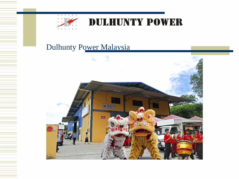
Dulhunty Power Malaysia

Production and warehouse area
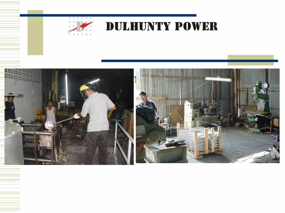
Production and warehouse area

Production and warehouse area
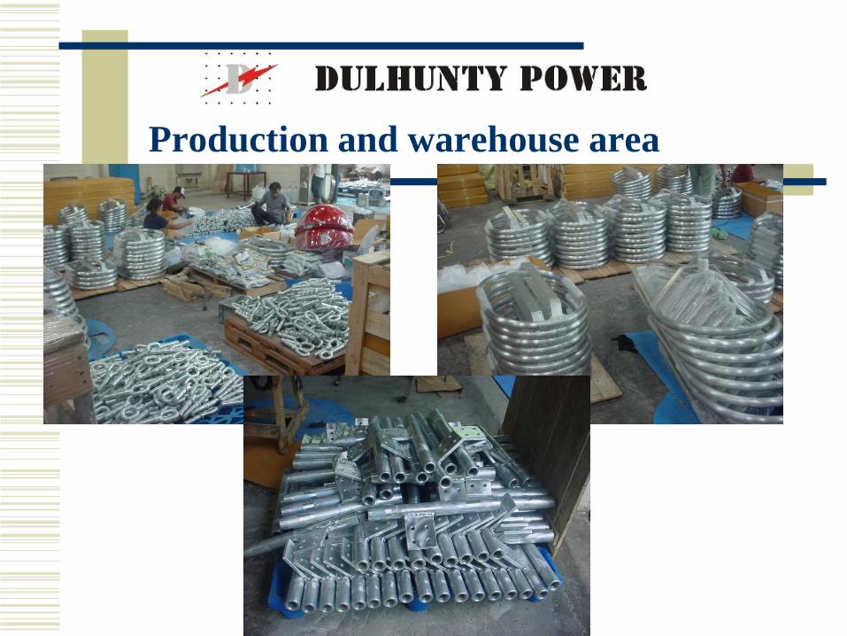
Production and warehouse area

Key Personnel include:
MR. PHILIP DULHUNTY Founder of Dulhunty Power
Life Honorary Member of CIGRE and IEEE who has over 50 years experience in the Electricity Supply Industry, and holds many patents for vibration control products.
PHILIP DULHUNTY- founded Dulmison in 1948
- Dulmison grew to be the largest manufacturer of products for power transmission and distribution products outside USA with factories in USA, UK, Thailand, Indonesia,Hong Kong
- Developed world class vibration control products
- Dulmison was sold to AWA in 1986, then sold to Morgan Crucible, UK in 1992 and then to Tyco USA in 2000.

Jack Roughan
- Former Global Engineering Manager for Dulmison for Tyco Energy division products with over 30 years experience in Electricity Supply Industry.
- Hired to expand the product range and markets for Dulhunty Group

Dr. Sarah Sun Chao is a specialist in
modelling of vibration phenomena.
Mr. Brian Mathieson is a specialist in field testing of vibration of transmission lines. Brian was formerly Dulmison New Zealand and Dulmison UK General Manager and has over 30 years experience in Electricity Supply Industry.

Mr Yun Wang
- specialist in aluminium gravity die casting and in casting
and heat treatment of cast iron.

CONSULTANTS
Tom Smart former Dulmison UK and PLP UK Engineering Manager with over 30 years experience in design of vibration control products.
Don McLean laboratory test instrumentation specialist

VIBRATION CONTROL: - Produce one of the best range of vibration control products in
the world
- Provide computer analysis of damper and spacer damper
performance
- Laboratory test facilities
- Field test services

Reference List
Dulhunty has sold its Vibration Control products to:
Australia Transgrid (NSW)
Powerlink (Queensland)
SPI Powernet (Victoria)
ETSA (SA)
Western Power (WA)
New Zealand Transpower

Reference List (continued)
USA AEP Jacksons Ferry – Wyoming 765kV
Dominion Power - 500kV project
Allegheny Power - Trail Project
Thailand EGAT
Malaysia TNB, SESCO
China Various power authorities.
Canada, Mexico, Peru

Vibration Dampers, Spacers,
and Spacer Dampers

CONDUCTOR VIBRATION
- Aeolian Vibration
- Subconductor Oscillation
- Galloping

Types of Vibration
Aeolian Vibration
Caused by Vortex shedding
Subconductor Oscillation
Wake induced movement
Galloping
Caused by ice buildup
AEOLIAN VIBRATION
Most common type of vibration affecting transmission lines.
Caused by low speed laminar wind flows that shed vortices from upper and lower surfaces alternately resulting in alternating lift forces on the conductor.
Frequency of vortex shedding is dependent on wind speed.

Vibration frequency is proportional to wind speed and
inversely proportional to conductor diameter.
Winds of 0.5 to 7 m/sec over flat terrain or large bodies
of water are most conducive to Aeolian Vibration.
Aeolian vibration occurs in the frequency range 5 to
100 Hz with maximum amplitudes approaching one
conductor diameter at the lower end of the frequency
range.

Vibration amplitude is determined by wind energy input
and the energy dissipated by the self damping of the
conductor, fittings, and external damping devices.

Vibration Damage
Vibration can cause serious damage

Vortex Shedding

Vortex Shedding

Vortex Shedding
0.5 to 6.5 m/sec
Frequency = 185 * v
d
v = wind speed (m/sec)
d = conductor diameter (mm)

Resonant Response
Resonant Response of Transmission Line
Conductors
Similar to guitar string
Lowest resonance (Fundamental) when
whole conductor moves like a guitar string

Fundamental Resonance
Frequency = *
S = Span Length
T = Tension
M = Mass
√ T / m1
2*S

Resonant Response
Resonant Response at each increment of
fundamental frequency

Resonant Response
At resonance, a small force will result in a
large vibration amplitude
Resonance occurs at every ¼ Hz
Lock in of vortex shedding to resonant
frequency

Vibration Damage
Vibration can cause serious damage

Vibration Dampers
Vibration Dampers are used to control
aeolian vibration
Vibration Dampers work by absorbing
energy

Standing Waves
The resonant pattern is called a Standing Wave
Standing waves are formed by the combination of
travelling wavesIncident Wave
Reflected Wave

A+B
NodeAntinode
Standing Waves

Spacing
(ED)Energy absorbed and
dissipated by Damper
(ER)
Reflected
Energy
(EI)
Incident
Energy
Energy absorbed
by span end (ESE)
Standing Waves with Damper
Node (Has non zero displacement amplitude)
Antinode
A+B
A-B

Damper placement
Factors affecting placement
- Range of Temperature
- Span Length
- Conductor Tension
- Terrain Considerations
- Wind Speed Range

0
10
20
30
40
50
60
0 5 10 15 20 25 30 35 40 45 50
Frequency (Hz)
Eff
icie
nc
y (
%)
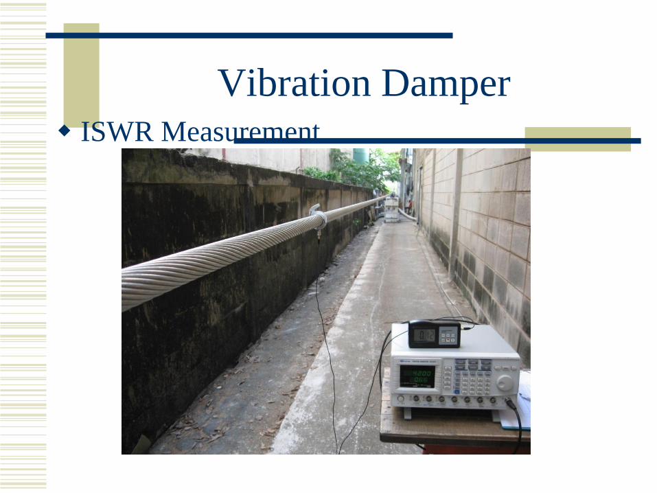
Vibration Damper
ISWR Measurement

Spacing
(ED)Energy absorbed and
dissipated by Damper
(ER)
Reflected
Energy
(EI)
Incident
Energy
Energy absorbed
by span end (ESE)
Energy Balance
Energy is put into the conductor by the wind
Energy is dissipated by the Dampers
and by conductor self damping

Energy Balance
• Vibration amplitude will increase until the energy
from the wind is balanced by the energy dissipated
by the dampers plus the energy lost in self damping
• PW = PD +PSD
• PW = f(Y/d) f3 d4
• PSD = f(Y4)
• PD = η * ½ √(T.m)

Energy Balance
Used to calculate
damper
requirements

Impedance Testing

Impedance Testing

Field Testing

Field Testing
Compare measured vibration with
“Safe” Amplitude
Estimate lifetime from comparison with
Fatigue curve.

Fatigue Life

Aeolian Vibration
Caused by Vortex Shedding
Characterised by
Low speed winds
5 to 50 Hz vibration
Up to 1 conductor diameter movement
May result in serious damage to conductor
strands

THE “4D SERIES” VIBRATION DAMPERS
FROM DULHUNTY POWER

THE “4D SERIES” VIBRATION DAMPERS
FROM DULHUNTY POWER
Designed to absorb vibration by dissipating the energy
of the vibration as heat in the messenger cable.
To work effectively, the damper impedance closely
matches to the characteristic impedance of the
conductor.

4D Dampers have four resonant
frequencies covering the whole spectrum
of vibration

Patented method of attachment the result of our research and development program with Australian Defense Industries (ADI).
Involves use of specially designed messenger cable that is pre and post formed to Dulhunty Power’s standard.
Weights are attached using a patented cementing process that only attaches outer strands of the messenger to the weight, thus allowing the inner strands to slide
longitudinally during dynamic bending.
Every 4D damper is proof tested for pull-off strength
performance in tests shows the method of attachment to be superior to dampers where weights are wedged, cast, or compressed on.

Tests conducted at Australia Defense Industries laboratories confirm the high efficiency of Dulhunty dampers over the full range of frequencies.
Field recordings confirm the performance of the Dulhunty 4D Dampers.

Spiral Dampers
Effective on
Small conductors
Steel earthwires
Location is not critical

Wire Products
Armour rods
Help to prevent damage at suspension points

Bundled Conductors
Bundled Conductors are subject to
Aeolian Vibration
Subconductor Oscillation
Galloping

Bundled Conductors
Aeolian Vibration
Same issues as for single conductors
Controlled in Bundle Conductors by energy
dissipation in Spacer Dampers
Number of Spacer dampers in each span
determined by energy balance

Subconductor Vibration
Wake Induced Movement on Bundled
conductors
Characterised by
Medium to Strong winds
Low frequency (up to 2 Hz )
Large amplitude circular motion

SUBCONDUCTOR OSCILLATION
Occurs on any bundled conductor configuration having
pairs of sub-conductors lying in the same horizontal
plane.
The upstream conductor sheds a turbulent wake which
results in complex interaction of aerodynamic and
mechanical forces on the downstream conductor –
thus causing sub-conductor oscillation.

SUBCONDUCTOR OSCILLATION
Sub-conductor oscillation is often seen as an anti-
phase elliptical motion of the sub-conductors with the
major axis of the ellipse in the horizontal plane.

Subconductor Oscillation
Complex Motion
Combined motion
produces “orbit”
of subconductors

Vibration frequency determined by mechanical
characteristics of bundle/spacer system and amplitude
by the balance between energy input by the wind and
energy dissipated by the aerodynamic and mechanical
damping of the system.

Subconductor Oscillation
Threshold Windspeed
Many Variables
Number of Subconductors
Spacing of Subconductors
Angle of Attack (Tilt) of Bundle
Type of Spacer Dampers
Location of Spacer Dampers

Usually occurs in wind speeds of 5 to 25 m/sec over
flat terrain or large bodies of water which results in
vibration frequencies of 0.5 to 4 Hz with amplitudes
sufficient to cause sub-conductor clashing in the
middle of sub spans.

Subconductor oscillation is a function of Wind Velocity
(V) and its Turbulence level, the Angle of Attack (OC)
the conductor Separation to Diameter Ratio (S/D) and
can occur on sections of the line or individual spans
and individual phases within a span.

Other than anti-phase, motion can be represented by
“bundle rocking” and “bundle snaking” (a bulk
sideways motion of the sub-conductors).

Subconductor Movement

Subconductor Vibration
Subconductor Oscillation may cause
subconductor clashing
Wear of suspension assemblies
Breakage or damage to spacer dampers

Subconductor Oscillation
Other Variables
Conductor Surface
Suspension and Tension String arrangements
Conductor Tension

Control of Subconductor Oscillation
Spacer Dampers
Reduce amplitude of Movement
Unequal Subspan Spacing
Increase threshold windspeed
S/D Ratio
Increase threshold windspeed

GALLOPING
Affects both single and bundled conduction.
Characterised by a low frequency (< 1 Hz), high amplitude
(several meters), and bulk vertical motion of a phase span with 1,
2 or 3 half wavelengths per span.
Can occur in both icing and non-icing conditions with normal wind
flows of approximately 5 – 40 m/sec over flat, unobstructed
terrain.

Galloping
Usually caused by ice buildup on conductors
Characterised by
Low frequency (1-2 Hz )
Movement may cause rapid damage to the
conductor and serious structural damage to
towers
Galloping
Areodynamic instability of conductors
May occur on single conductors or bundled
conductors
Large amplitudes of motion
May result in line outages due to flashover

Galloping

Galloping Damage
Breakage of Spacer Damper

Galloping Damage
Tower Failure

Galloping
Controlled by
Remove the ice, or prevent if from forming
Use of interphase spacers
Use of detuning pendulum on conductors
Use of aerodynamic drag dampers.

Galloping
Detuning Pendulum

Galloping
Aerodynamic Drag Damper
Spacer Dampers
Spacer Dampers are Designed to Control
Subconductor Oscillation
Aeolian Vibration
Assist with control of Galloping

SPACER-DAMPERS
Maintain separation of sub-conductors
Control aeolian vibration
Control subconductor oscillation

Contoured to eliminate corona and minimize
R.I.V.
Allow maximum clamping pressure without
damage to the conductor

SPACER DAMPERS
Twin, Triple, Quad and Hex Configurations

Subspan Spacing
Staggered Spacing for control of Subconductor
oscillation.
End span spacing for rollover recovery.
Testing of Spacer Dampers
Mechanical Test facilities at Dulhunty
Power Thailand and China factory
locations
Electrical Tests in EGAT Bang Na
Laboratory, and also Wuhan HV
research institute.

Testing of Spacer Dampers
Damping Performance
Log Decrement Test
Strength
Compression & Tension
Fatigue performance
Fatigue tests
Field Tests

Compression Test Tension Test
Testing of Spacer Dampers

SPACER DAMPER TEST RIG for
Longitudinal Deflection Test
Vertical Deflection Test
Clamp Slip Test

SPACER DAMPER TEST RIG for
Transverse (Torsional) Deflection Test

Fatigue Tests
Vertical Longitudinal Transverse
Testing of Spacer Dampers

Field Testing of Spacer Dampers

QUAD SPACER DAMPERFlexible Hinge
- Provide articulation in all
directions
- High Fatigue endurance
- High resistance to weathering
and ageing
- Impervious to Ozone
- Wide temperature range
- Controlled Resistance
- Optimised stiffness and
Damping
Clamps
- Minimum Corona & RI
- High Slip Strength without
damage to
conductor
- Galvanised, Stainless or
Aluminium
Shearhead bolts
- Belleville washers available
Construction
- high strength Aluminium Alloy
- arms angled to give horizontal
and vertical flexibility
- Optimised mass and rotational
inertia
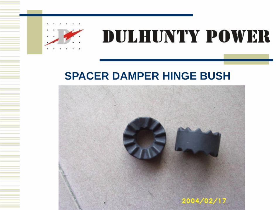
SPACER DAMPER HINGE BUSH

DULHUNTY TOP
03
TOP
03
030
3
03
03
CLAMP KEEPER
DAMPING DISC
STEEL GRADE 8.8 GALV. THREAD LENGTH 26mm
THREAD TAPPED 0.4mm OVERSIZE AFTER GALV.
6SD:PKE:014
6
SD:DD:015 12
10
11
6
6
12
Notes:
10
11
ARM MOVEMENT±7.5° NOMINAL
2
5
1
12
CLAMP LINER12SD:PCL:F16
HINGE PIN6SD:PHP:017
FASTENER PIN68
'O' RING69
ARM MOVEMENT±15° NOMINAL
4
6
3
8
7
9
Ø762mm (30") P
CD
40
SD:PFP:01

TRIPLE SPACER DAMPER

TWIN SPACER DAMPER

TWIN SPACER

AEP Spacer Dampers
Specification included high requirement for
vibration control
55m max subspan length
Staggered Subspan lengths
Conductor clamp
Use quick action clamps for ease of installation

Delivery
Samples 6 weeks
Production 1600 per week after approval of samples


Spacer Damper for NGC
Logarithmic
decrement
= 0.98
