duopexgas manual - auspex · duopexgas manual wm-021044 wm-022149 smkp 25517. the duopex gas pipe...
TRANSCRIPT

DUOPEXGASMANUAL
WM-021044WM-022149
SMKP 25517
The Duopex Gas pipe anD fiTTinG sysTem is DesiGneD To make every job quick anD easy. iT proviDes a revoluTionary alTernaTive for The professional plumber anD GasfiTTer.
Duopex Gas manual
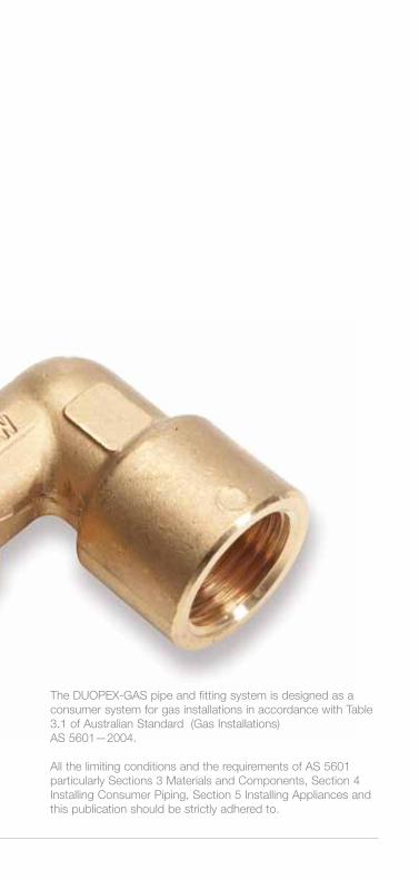
The Duopex-Gas pipe and fitting system is designed as a consumer system for gas installations in accordance with Table 3.1 of australian standard (Gas installations)as 5601—2004.
all the limiting conditions and the requirements of as 5601 particularly sections 3 materials and components, section 4 installing consumer piping, section 5 installing appliances and this publication should be strictly adhered to.

The pipe has been tested in accordance with as4176 and carries license number 21044 and standardsmark.
The Duopex Gas pipe has many advantages. some are listed below:
• Impermeabilitytooxygenandgasesingeneral.
• Formstabilityduringinstallation,foranexamplein a curve.
• Lowthermalconductivitylevel.
• Lightweightduringtransportandinstallation.
• Thermalexpansionislowerthanthatofothertubes.
• Verygoodbehaviourinthepresenceoffirethanks to the metal layer and low steam emission during combustion.
• Lowerpressurelossthankstothesmoothinnerlayer.
DUOPEX GAS PIPE
The Duopex Gas pipe is a multi layer or composite pipe system.
it consists of an inner layer of cross-linked polyethylene (pe-x), an adhesive layer, an aluminium layer, an adhesive layer, an outer layer of cross-linked polyethylene, which is effectively a 5-layer pipe.
02_Duopex Gas manual
outer layer Cross-linked polyethylene
adhesive layermiddle layer Aluminium
inner layer Cross-linked polyethylene
adhesive layer
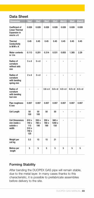
Forming Stability
after bending the Duopex Gas pipe will remain stable, due to the metal layer. in many cases thanks to this characteristic, it is possible to prefabricate assemblies before delivery to the site.
Duopex Gas manual_03
Dimension 16x2 20x2 26x3 32x3 40x3.5 50x4 63x4.5
Coefficient of 0.026 0.026 0.026 0.026 0.026 0.026 0.026 Linear Thermal Expansion in mm/m x K
Thermal 0.45 0.45 0.45 0.45 0.45 0.45 0.45 Conductivity in W/M x K
Water contents 0.113 0.201 0.314 0.531 0.855 1.385 2.29 in 1/m
Radius of 5 x d 5 x d - - - - - curvature without aids mm
Radius of 2 x d 3 x d - - - - - curvature with bending spring mm
Radius of - - 3.6 x d 3.6 x d 4.0 x d 4.0 x d 4.5 x d curvature with bending tool mm
Pipe roughness 0.007 0.007 0.007 0.007 0.007 0.007 0.007 K mm
Coil Length 50 50 50 50 - - - 100 100
Coil Dimensions 610 x 550 x 550 x 940 x - - - mm inside x 740 x 780 x 780 x 1200 x outside x 115 190 190 150 width 510 x 740 x 120
Weight per 5.5 15 15 21 coil kg
Metres per 5 5 5 5 5 5 5 length
Data Sheet

Minimum Bending Radiibending can be made manually however if tighter bends are required bending springs or bending tools can be used.
04_Duopex Gas manual
DUOPEX GAS PIPE
Pipe Dimension Max Pipe clip (mm) clearance (cm)
16x2.0 100 20x2.0 125 26x3.0 150 32x3.0 200 40x3.5 200 50x4.0 250 63x4.5 250
Thermal Changes in Lengthheating and cooling cause pipe length changes.
ThecoefficientofexpansionofDUOPEXGAScompositepipesis0.026mm/mxk
Spacing of Supporting Devises see also as5601 Table 4.2
Pipe Bending Bending radii Dimension radii without with internal (mm) tools pipe bending spring
16x2.0 5xda 2.0xda
20x2.0 5xda 3.0xda
Bending radii with bending tools 26x3.0 3.6xda
32x3.0 3.6xda
40x3.5 4.0xda
50x4.0 4.0xda
63x4.5 4.5xda
Thermal changes in length
pipe length changes are caused by heating and cooling.
The coefficient of expansionofDUOPEX
composite pipes is 0.026mm/mxK.
Example Temperature
differential 5T 50kpipe length l 5 mCoefficientofexpansiona 0.026mm/m.KLinearexpansion5l 6.5 mm
5L =axLx5T =0.0026mm/m.Kx5mx50K = 6.5 mm
synthetic clips must be used.

Fire and Excessive Heatkeep Duopex Gas pipe a minimum of 500mm from sources of high heat such as heating appliances and flues from heating appliances.
keep Duopex Gas pipe 1500mm from slow combustion type stoves and flues used to heat hot water or cooking. (Wet back type).
leave 300mm minimum space between Duopex pipe and recessed electric light fittings.
Duopex pipe should not be positioned within 150mm of gas or central heating vents or flues.
UV ResistanceDuopex Gas pipes must be protected against direct sunlight or uv radiation. consequently, Duopex Gas pipes must be covered during transport or storage if they have been removed from their original packaging. When Duopex Gas pipes are used in a protective tube adequate uv protection is assured during the installation phase. furthermore, jackets made from insulating material can undertake the function of uv protection with Duopex Gas pipes.
Chemical ResistanceThe chemical properties of polyethylene are significantly improved by cross-linking. multi layer pipe with cross-linked polyethene has been approved for use in as5601. This includes natural gas and lpG. for specific gasesotherthanthesepleasecontacttheDuopexrepresentative.
Duopex Gas manual_05
DUOPEX GAS PIPE
Gas Standard AS 5601
4.11.4 - composite pipe installed above ground shall beprotectedagainstdegradationfromexposuretoultra violet light.note: a typical means of protection is sleeving or wrapping with a suitable protective material.

DUOPEX GAS pipes are resistant to the following media:• Concrete,plaster,mortar,andcement.
• DisinfectantsandcleaningagentsaccordingtoDVGWworksheet W 291 and Din 2000.
• Allnaturalpotablewaterconstituents.
• Corrosion-protectionagentsaccordingtoDIN1988part 4.
DUOPEX GAS pipes must be protected against: • Directcontactwithbitumenorbitumenstrips.
• Pipesmustbeprotectedagainstgreases,solvents and oils.
• ContaminatedareasasdefinedbyAS5601andas3500.
if the Duopex Gas pipe installation system is used in areaswhere,forexample,aggressivegases,permanentlyacting moistures or building materials containing chlorine are to be encountered, the fittings have to be protected using suitable jacketing. This also applies to contact with screed, concrete, mortar or plaster.
always consult the manufacturer for details.
The pipes have been tested in accordance with aTs 5200.478,whichwaswrittentoaddressthedimensionallimitations within as4176. The testing requirements of this technical specification match those in as4176. The pipes carry standards mark and licence number 21044.
06_Duopex Gas manual
DUOPEX GAS PIPE

DUOPEX GAS FITTINGS
The Duopex Gas fittings are manufactured from dezincification resistance (Dr) brass with a stainless steel crimp ring and joined to the pipe using a precision and specific crimping tool.
The fittings have been tested in accordance with aTs 5200.478.Thetestingrequirementsofthistechnicalspecification match those in as4176. The fittings carry watermark and licence number 21069.
To increase joint performance all Duopex Gas crimp fittings are characterised by a plastic holding ring which has 2 important functions:
1. as a locating ring that matches the Duopex Gas jaws for a perfect crimp position.
2. it allows the installer to visually check when the pipe is correctly fitted on the fitting.
These pipe fittings are available for Duopex Gas in sizes ranging from 16 to 63mm.
Duopex Gas crimp fittings are classified as a permanent joint in accordance with as 5601.
Duopex Gas manual_07
Female BSP Tee Forthecompleterangeoffittingsseepages18to24.
08_Duopex Gas manual
AUSPEX JOINTING TOOLS
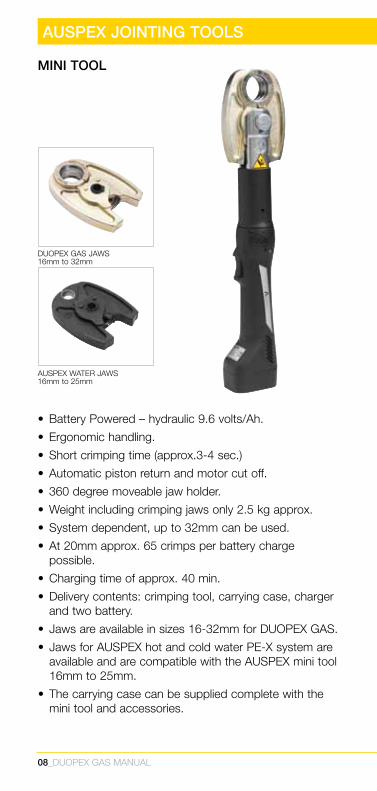
MINI TOOL
• BatteryPowered–hydraulic9.6volts/Ah.
• Ergonomichandling.
• Shortcrimpingtime(approx.3-4sec.)
• Automaticpistonreturnandmotorcutoff.
• 360degreemoveablejawholder.
• Weightincludingcrimpingjawsonly2.5kgapprox.
• Systemdependent,upto32mmcanbeused.
• At20mmapprox.65crimpsperbatterychargepossible.
• Chargingtimeofapprox.40min.
• Deliverycontents:crimpingtool,carryingcase,chargerand two battery.
• Jawsareavailableinsizes16-32mmforDUOPEXGAS.
• JawsforAUSPEXhotandcoldwaterPE-Xsystemareavailable and are compatible with the auspex mini tool 16mm to 25mm.
• Thecarryingcasecanbesuppliedcompletewiththemini tool and accessories.
auspex WaTer jaWs 16mm to 25mm
Duopex Gas jaWs 16mm to 32mm
Duopex Gas manual_09
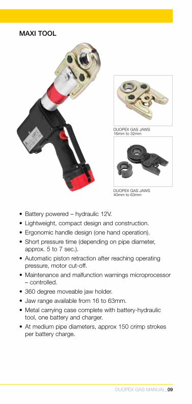
MAXI TOOL
• Batterypowered–hydraulic12V.
• Lightweight,compactdesignandconstruction.
• Ergonomichandledesign(onehandoperation).
• Shortpressuretime(dependingonpipediameter,approx.5to7sec.).
• Automaticpistonretractionafterreachingoperatingpressure, motor cut-off.
• Maintenanceandmalfunctionwarningsmicroprocessor–controlled.
• 360degreemoveablejawholder.
• Jawrangeavailablefrom16to63mm.
• Metalcarryingcasecompletewithbattery-hydraulictool, one battery and charger.
• Atmediumpipediameters,approx150crimpstrokesper battery charge.
Duopex Gas jaWs 40mm to 63mm
Duopex Gas jaWs 16mm to 32mm

MAkING A JOINT
It is most important that the tool manual supplied with the tool is read in its entirety and the user becomes familiar with the maintenance, precautions and the proper use of this tool.
The following describes, in general terms, the jointing procedures using the auspex mini Tool but should not be regarded as a substitute for reading and applying the detailed instructions contained in the tool manual.
1 ensure that the battery is fully charged and attach it to the tool.
2 select the jaw size to suit the fitting to be crimped. Thejawsmustbeexaminedintermsofpossibledamage, or dirt in the compression area.
3 To change the jaw push the pin in and at the same time twist it in an anti-clockwise direction. The pin should then spring back.
4 insert the jaws and line up the holes in the tool with the hole in the jaw.
5 push the pin through the hole in the jaw until it locks in position.
10_Duopex Gas manual

Duopex Gas manual_11
6 cut the pipe to the required length with the recommended multi layer pipe cutters.
7a clean the pipe by using the deburring tool. insert the calibrating tool into the pipe, and alternately turn in a clockwise and in a counter-clockwise direction.
7b insert the calibrating/deburring tool into the pipe, and then alternately turn in a clockwise and in a counter-clockwise direction.
OR

12_Duopex Gas manual
8 insert the pipe into the fitting and under the stainless steel ring and push the pipe until it is visible in the slots of the plastic ring. This ensures you have pushed the pipe home.
10 With the jaws open place the fitting inside the jaws so that the raised section of the plastic ring fits into the slot in the jaws. release the jaws so they fit snugly over the fitting ensuring that the raised section of the plastic ring fit into the slots in the jaw.
9 by squeezing the back of the jaw the jaws will open. if you look at the machined profile on the inside of the jaws you will note a slot on each side of the profile.
MAkING A JOINT
witnesshole
Duopex Gas manual_13
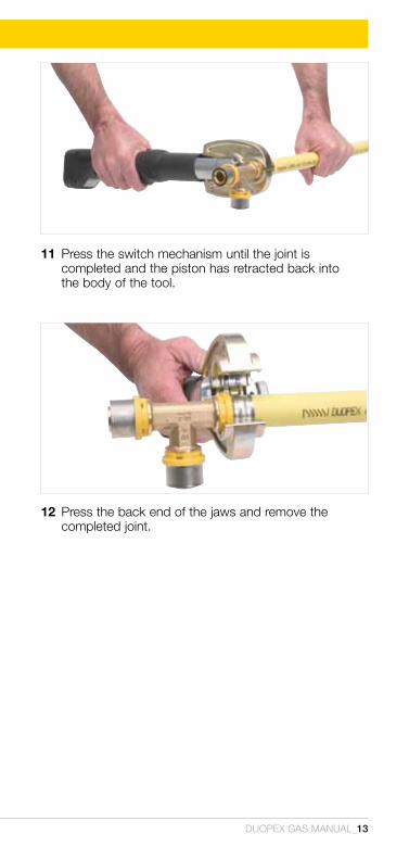
11 press the switch mechanism until the joint is completed and the piston has retracted back into the body of the tool.
12 press the back end of the jaws and remove the completed joint.
14_Duopex Gas manual
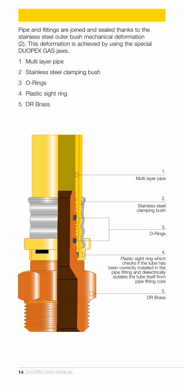
pipe and fittings are joined and sealed thanks to the stainless steel outer bush mechanical deformation (2). This deformation is achieved by using the special Duopex Gas jaws.
1 multi layer pipe
2 stainless steel clamping bush
3 o-rings
4 plastic sight ring
5 Dr brass
1.
multi layer pipe
2.
stainless steel clamping bush
3.o-rings
4.plastic sight ring which checks if the tube has
been correctly installed in the pipe fitting and dielectrically isolates the tube itself from
pipe fitting core
5.Dr brass
Duopex Gas manual_15
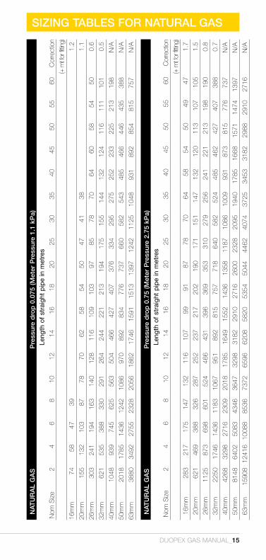
SIzING TABLES FOR NATURAL GASN
ATU
RA
L G
AS
Pre
ssur
e d
rop
0.0
75 (M
eter
Pre
ssur
e 1.
1 kP
a)Le
ngth
of
stra
ight
pip
e in
met
res
Nom
Siz
e2
46
810
1214
1618
2025
3035
4045
5055
60C
orre
ctio
n
(+ m
t for
fittin
g)
16m
m74
5847
391.
2
20m
m15
513
210
387
7870
6258
5450
4741
381.
1
26m
m30
324
119
416
314
012
811
610
910
397
8578
7064
6058
5450
0.6
32m
m62
153
538
833
029
126
424
422
121
319
417
515
514
413
212
411
611
110
10.
5
40m
m10
4893
974
562
556
350
446
642
740
737
633
429
527
525
223
322
521
319
8N
/A
50m
m20
1817
8514
3612
4210
8697
089
283
477
673
766
058
254
348
546
644
643
538
8N
/A
63m
m38
8034
9227
5523
2820
5618
6217
4615
9115
1313
9712
4211
2510
4893
189
285
481
575
7N
/A
NAT
UR
AL
GA
S
Pre
ssur
e d
rop
0.7
5 (M
eter
Pre
ssur
e 2.
75 k
Pa)
Leng
th o
f st
raig
ht p
ipe
in m
etre
s
Nom
Siz
e2
46
810
1214
1618
2025
3035
4045
5055
60C
orre
ctio
n
(+ m
t for
fittin
g)
16m
m28
321
717
514
713
211
610
799
9187
7870
6458
5450
4947
1.7
20m
m62
146
938
832
628
725
223
721
720
219
017
115
114
713
212
011
310
710
51.
5
26m
m11
2587
369
860
152
446
643
139
636
935
331
027
925
624
122
121
319
819
00.
8
32m
m22
5017
4614
3611
8310
6795
189
281
575
771
864
058
252
448
546
242
740
738
80.
7
40m
m42
6832
9827
1623
0920
1817
8516
4915
5214
3613
5811
8710
8610
0993
187
381
577
673
7N
/A
50m
m81
4864
0250
8343
4636
4732
9831
8229
1027
1626
0023
2820
9519
4017
8516
6815
7114
7413
97N
/A
63m
m15
908
1241
610
088
8536
7372
6596
6208
5820
5354
5044
4462
4074
3725
3453
3182
2988
2910
2716
N/A
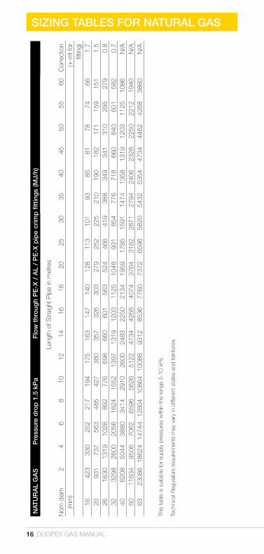
SIzING TABLES FOR NATURAL GAS
16_Duopex Gas manual
This
tabl
e is
sui
tabl
e fo
r su
pply
pre
ssur
es w
ithin
the
rang
e 5-
10 k
Pa
Tech
nica
l Reg
ulat
ors
requ
irem
ents
may
var
y in
diff
eren
t sta
tes
and
terri
torie
s
NAT
UR
AL
GA
S
Pre
ssur
e d
rop
1.5
kP
a
Flo
w t
hro
ugh
PE
-X /
AL
/ P
E-X
pip
e cr
imp
fitt
ing
s (M
J/h)
Leng
th o
f Stra
ight
Pip
e in
met
res
Nom
dia
m2
4 6
810
12
14
1618
20
2530
35
4045
50
5560
Cor
rect
ion
(mm
)(+
mt f
or
fittin
g)16
423
330
252
217
194
175
163
147
140
128
113
101
9385
8178
7466
1.7
2093
173
756
348
542
738
035
732
630
327
925
222
521
019
018
217
115
915
11.
526
1630
1319
1028
892
776
698
660
601
563
524
466
419
388
349
341
310
295
279
0.8
3232
9826
0020
5618
2415
5213
9713
1912
0311
2510
4893
185
477
671
866
064
060
158
20.
740
6208
5044
3880
3414
2910
2600
2483
2250
2134
1959
1785
1591
1474
1358
1319
1203
1125
1086
N/A
5011
834
9506
7062
6596
5626
5122
4734
4268
4074
3764
3182
2871
2794
2406
2328
2250
2212
1940
N/A
6323
086
1862
414
744
1280
410
864
1008
893
1285
3677
6073
7265
9658
2054
3253
5447
3444
6242
6838
80N
/A

SIzING TABLES FOR LPG
Duopex Gas manual_17
LP
G
Pre
ssur
e D
rop
0.2
5kP
a (P
ress
ure
Sup
ply
2.7
5kP
a) F
low
thr
oug
h P
E-X
/AL/
PE
-X p
ipe
crim
p fi
ttin
gs
(MJ/
h)Le
ngth
of S
traig
ht P
ipe
in m
etre
sN
om S
ize
24
68
1012
1416
1820
2530
3540
4550
5560
Cor
rect
ion
(mm
)(+
mt f
or
fittin
g)16
238
190
152
128
114
100
95N
AN
AN
AN
AN
AN
AN
AN
AN
AN
AN
A1.
720
532
418
333
285
247
219
204
190
166
169
147
133
119
114
105
100
95N
A1.
526
998
760
618
523
447
418
380
352
323
314
276
247
223
209
190
181
171
166
0.8
3219
9515
3012
3510
4592
285
576
071
366
562
756
149
444
742
839
938
035
234
20.
740
3800
2945
2375
2043
1805
1615
1473
1378
1283
1235
1055
950
874
808
760
713
665
646
NA
5072
2056
0545
6038
9534
2030
4028
5026
6024
7023
7520
9018
8117
1016
1515
6814
2513
3012
45N
A63
1330
010
925
8930
7600
6650
5890
5605
5130
4750
4655
3990
3610
3230
3040
2850
2755
2565
2470
NA
LPG
P
ress
ure
Dro
p 1
0kP
a
(Pre
ssur
e S
upp
ly 7
0kP
a) F
low
thr
oug
h P
E-X
/AL/
PE
-X p
ipe
crim
p f
ittin
gs
(MJ/
h)Le
ngth
of S
traig
ht P
ipe
in m
etre
sN
om S
ize
24
68
10
1214
16
1820
25
30
3540
4550
55
60C
orre
ctio
n (m
m)
(+ m
t for
fittin
g)16
2090
1615
1292
1064
950
855
798
732
684
627
570
513
475
428
409
390
361
342
2041
8034
2028
5023
7520
9019
0016
6316
1515
2014
2512
3511
4010
4595
090
385
579
876
026
7600
6175
5130
4275
3800
3420
3135
2850
2755
2565
2280
2090
1900
1805
1663
1615
1473
1425
3216
150
1235
010
450
8550
7600
6745
6270
5700
5510
5130
4560
3990
3800
3515
3325
3135
2945
2850
4029
450
2375
019
760
1615
014
250
1282
512
065
1111
510
450
9500
8550
7790
7125
6650
6175
5890
5605
5320
5052
250
4560
038
000
3087
527
550
2470
022
800
2090
019
950
1852
516
625
1615
013
775
1282
511
875
1140
010
545
1026
063
9975
087
780
7220
060
800
5510
047
500
4417
541
800
3800
036
100
3230
028
975
2707
524
700
2327
522
325
2090
019
950

18_Duopex Gas manual
DUOPEXGASPRODUcT
LiST
PIPES
available in 5m lengths
Threaded fittings should not be heat re-fabricated. use approved pastes/jointing compounds.
UV SLEEViNG
Gpm401605Gsl suitable for 16mm DuopexGaspipe
Gpm412005Gsl suitable for 20mm DuopexGaspipe
Gpm422605Gsl suitable for 26mm DuopexGaspipe
PiPE STRAiGhT
16mm x 5m Gpm40160520mm x 5m Gpm41200526mm x 5m Gpm42260532mm x 5m Gpm43320540mm x 5m Gpm44400550mm x 5m Gpm45500563mm x 5m Gpm466305
PiPE cOiLS
16 x 50m Gpm40165016 x 100m Gpm401610020 x 50m Gpm41205020 x 100m Gpm412010026 x 50m Gpm42265032 x 50m Gpm433250
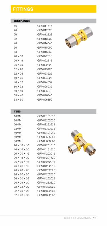
FITTINGS
Duopex Gas manual_19
cOUPLiNGS
16 Gpm011616
20 Gpm012020
26 Gpm012626
32 Gpm013232
40 Gpm014040
50 Gpm015050
63 Gpm016363
20 x 16 Gpm022016
26 x 16 Gpm022616
26 x 20 Gpm022620
32 x 20 Gpm023220
32 x 26 Gpm023226
40 x 26 Gpm024026
40 x 32 Gpm024032
50 x 32 Gpm025032
50 x 40 Gpm025040
63 x 40 Gpm026340
63 x 50 Gpm026350
TEES
16mm Gpm03161616
20mm Gpm03202020
26mm Gpm03262626
32mm Gpm03323232
40mm Gpm03404040
50mm Gpm03505050
63mm Gpm03636363
20 x 16 x 16 Gpm04201616
16 x 16 x 20 Gpm04161620
20 x 20 x 16 Gpm04202016
20 x 16 x 20 Gpm04201620
26 x 20 x 16 Gpm04262016
26 x 26 x 16 Gpm04262616
20 x 20 x 26 Gpm04202026
26 x 20 x 20 Gpm04262020
26 x 20 x 26 Gpm04262026
26 x 26 x 20 Gpm04262620
32 x 32 x 20 Gpm04323220
32 x 26 x 26 Gpm04322626
32 x 26 x 32 Gpm04322632
20_Duopex Gas manual
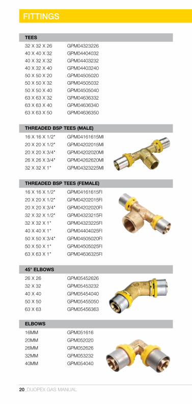
FITTINGS
TEES
32 x 32 x 26 Gpm04323226
40 x 40 x 32 Gpm04404032
40 x 32 x 32 Gpm04403232
40 x 32 x 40 Gpm04403240
50 x 50 x 20 Gpm04505020
50 x 50 x 32 Gpm04505032
50 x 50 x 40 Gpm04505040
63 x 63 x 32 Gpm04636332
63 x 63 x 40 Gpm04636340
63 x 63 x 50 Gpm04636350
ThREADED BSP TEES (MALE)
16 x 16 x 1/2" Gpm04161615mi
20 x 20 x 1/2" Gpm04202015mi
20 x 20 x 3/4" Gpm04202020mi
26 x 26 x 3/4" Gpm04262620mi
32 x 32 x 1" Gpm04323225mi
ThREADED BSP TEES (FEMALE)
16 x 16 x 1/2" Gpm04161615fi
20 x 20 x 1/2" Gpm04202015fi
20 x 20 x 3/4" Gpm04202020fi
32 x 32 x 1/2" Gpm04323215fi
32 x 32 x 1" Gpm04323225fi
40 x 40 x 1" Gpm04404025fi
50 x 50 x 3/4" Gpm04505020fi
50 x 50 x 1" Gpm04505025fi
63 x 63 x 1" Gpm04636325fi
45° ELBOwS
26 x 26 Gpm05452626
32 x 32 Gpm05453232
40 x 40 Gpm05454040
50 x 50 Gpm05455050
63 x 63 Gpm05456363
ELBOwS
16mm Gpm051616
20mm Gpm052020
26mm Gpm052626
32mm Gpm053232
40mm Gpm054040

These fittings are not for heat related re-fabrication. Do not braze onto threads. use approved pastes/jointing compounds.
Duopex Gas manual_21
ELBOwS
50mm Gpm055050
63mm Gpm056363
ThREADED BSP ELBOwS (FEMALE)
16 x 1/2" Gpm051615fi
20 x 1/2" Gpm052015fi
20 x 3/4" Gpm052020fi
26 x 3/4" Gpm052620fi
32 x 1" Gpm053226fi
40 x 1 1/4" Gpm054032fi
50 x 1 1/2" Gpm055040fi
ThREADED BSP ELBOwS (MALE)
16 x 1/2" Gpm051615mi
20 x 1/2" Gpm052015mi
20 x 3/4" Gpm052020mi
26 x 3/4" Gpm052620mi
32 x 1" Gpm053225mi
40 x 1 1/4" Gpm054032mi
50 x 1 1/2" Gpm055040mi
63 x 2" Gpm056350mi
LUGGED ELBOwS (MALE)
16 x 1/2" (73mm) Gpm061615s
16X1/2"(88MM) GPM061615L
20 x 3/4" (200mm) Gpm062020
FITTINGS
FITTINGS
22_DUOPEX GAS MANUAL
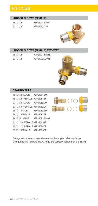
LUGGED ELBOwS (FEMALE)
16 x 1/2" Gpm071615fi
20 x 1/2" Gpm072015
LUGGED ELBOwS (FEMALE) TwO wAy
16 x 1/2" Gpm07161615
20 x 1/2" Gpm07202015
BRAZiNG TAiLS
16X1/2"MALE GPM0816M
16X1/2"FEMALE GPM0816F
20X3/4"MALE GPM0820M
20 x 3/4"FEMALE GPM0820F
26X1"MALE GPM0826M
26X1"FEMALE GPM0826F
26 x 3/4" male GPM082520M
32 x 1 1/4FEMALEGPM0832F
40 x 11/2FEMALEGPM0840F
50X2"FEMALE GPM0850F
o rings and stainless steel sleeve must be applied after soldering and quenching. ensure that o rings are correctly located on the fitting.
DUOPEX GAS MANUAL_23
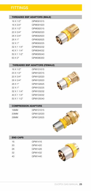
ThREADED BSP ADAPTORS (MALE)
16 x 1/2" Gpm091615
16 x 3/4" Gpm091620
20 x 1/2" Gpm092015
20 x 3/4" Gpm092020
26 x 3/4" Gpm092620
26 x 1" Gpm092625
32 x 1" Gpm093225
32 x 1 1/4" Gpm093232
40 x 1 1/4" Gpm094032
50 x 1 1/2" Gpm095040
63 x 2" Gpm096350
ThREADED BSP ADAPTORS (FEMALE)
16 x 1/2" Gpm101615
20 x 1/2" Gpm102015
20 x 3/4" Gpm102020
26 x 3/4" Gpm102620
26 x 1" Gpm102625
32 x 1" Gpm103225
32 x 1 1/4" Gpm103232
40 x 1 1/4" Gpm104032
50 x 1 1/2" Gpm105040
cOMPRESSiON ADAPTORS
16mm Gpm131615
20mm Gpm132020
26mm Gpm132625
END cAPS
16 Gpm1416
20 Gpm1420
26 Gpm1426
32 Gpm1432
40 Gpm1440
FITTINGS
24_Duopex Gas manual
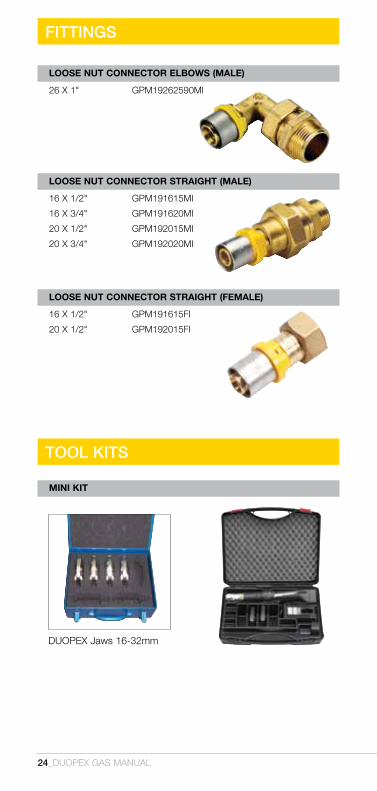
TOOL kITS
Duopex jaws 16-32mm
MiNi KiT
LOOSE NUT cONNEcTOR ELBOwS (MALE)
26 x 1" Gpm19262590mi
LOOSE NUT cONNEcTOR STRAiGhT (MALE)
16 x 1/2" Gpm191615mi
16 x 3/4" Gpm191620mi
20 x 1/2" Gpm192015mi
20 x 3/4" Gpm192020mi
LOOSE NUT cONNEcTOR STRAiGhT (FEMALE)
16 x 1/2" Gpm191615fi
20 x 1/2" Gpm192015fi
FITTINGS

TOOL kITS
Duopex Gas manual_25
ACCESSORIES
Duopex jaws 40-63mm
cUTTiNG TOOL cALiBRATiNG TOOL
cALiBRATiNG/DEBURRiNG TOOLS
50mm
Gpm21x50
63mm
Gpm21x63
MAXi KiT
Tool specific for multi layered pipe
16-40mm
GPM7498X1640DP
Gpm231026

Duopex Gas and Auspex are Trademarks belonging to the GSA Group of Companies
PO BOX 4271 Dandenong South Victoria 3164Telephone (03) 9770 3600 Facsimile (03) 9768 3415
www.duopex.com.au
WM-021044WM-022149
All statements, information and data given herein are believed to be accurate and reliable but are presented without guarantee or responsibility of any kind, expressed or implied, on our part.
Neither Auspex nor any of its employees, contractors or agents will be liable in tort, contract or in any other way for any direct or indirect claim, loss, damage, cost, injury or death (“Claim”) suffered by any party whether due to any action or inaction of Auspex to the extent that the Claim is caused or contributed to by:
1. the customer or any other party, including by giving Auspex incorrect or incomplete information or instruction.2. an error in any relevant Australian Standard an event that is otherwise beyond the reasonable control of Auspex
V3
SMKP 25517