durability-design of pre-cast concrete structural … · literature of the probabilistic analysis...
TRANSCRIPT

BUDAPEST UNIVERSITY OF TECHNOLOGY AND ECONOMICS FACULTY OF CIVIL ENGINEERING
DEPARTMENT OF STRUCTURAL ENGINEERING 1111 Budapest, Bertalan Lajos u. 2.
DURABILITY-DESIGN OF PRE-CAST CONCRETE STRUCTURAL MEMBERS
PhD thesis
Kálmán Koris civil engineer, MSC
Supervisor: Dr. István Bódi, PhD Associate Professor
Budapest, September 2008.

Kálmán KORIS Durability-design of pre-cast concrete structural members
- 1 -
TABLE OF CONTENT 1. INTRODUCTION.......................................................................................................................2
1.1. Statement of the problem......................................................................................................2 1.2. Probabilistic methods in structural engineering ...................................................................3
1.2.1. Historical review ......................................................................................................3 1.2.2. Analytical methods ...................................................................................................3 1.2.3. Numerical methods ...................................................................................................5 1.2.4. Literature of the probabilistic analysis of concrete structures ................................6
2. PROBABILISTIC APPROACH FOR THE DURABILITY-DESIGN ......................................8 2.1. Definition of the probability of failure .................................................................................8 2.2. Expected probability of failure...........................................................................................10 2.3. Evaluation of the probability of failure ..............................................................................11 2.4. Evaluation of the mean value of structural resistance........................................................12
2.4.1. Application of finite element method......................................................................12 2.4.2. Non-linear behavior of reinforced and prestressed concrete.................................14 2.4.3. Evaluation of the bending moment-curvature diagrams ........................................16
2.5. Evaluation of scatter of structural resistance by stochastic finite element method............17 2.5.1. The variational approach .......................................................................................17 2.5.2. Stochastic finite element formulation .....................................................................19
2.6. Terms of application...........................................................................................................21 3. DETERMINATION OF PROCESS PARAMETERS ..............................................................22
3.1. Initial value of material properties .....................................................................................22 3.2. Evaluation of process parameters as a function of time.....................................................30
3.2.1. Effective prestressing stress ...................................................................................31 3.2.2. Geometry of the cross-section ................................................................................32 3.2.3. Strength of materials ..............................................................................................32 3.2.4. Carbonation induced corrosion of steel bars and tendons ....................................33 3.2.5. Load effect ..............................................................................................................35
4. APPLICATION OF THE IMPLEMENTED DESIGN METHOD...........................................37 4.1. Verification of the method by bending tests ......................................................................37
4.1.1. Analyzed beams and test results .............................................................................37 4.1.2. Results of SFEM analysis .......................................................................................38
4.2. Durability-design of prestressed concrete beams...............................................................46 4.2.1. Analyzed beam types and the calculation algorithm..............................................46 4.2.2. Analysis of beam type “4000”................................................................................49 4.2.3. Analysis of beam type “4700”................................................................................59 4.2.4. Numerical example for the durability-design of beam “4000”..............................68 4.2.5. Durability analysis of existing structural members................................................69
5. NEW RESULTS OF THE PHD THESIS .................................................................................71
6. POSSIBLE ENHANCEMENTS OF THE METHOD ..............................................................73
7. REFERENCES ..........................................................................................................................74
8. APPENDIX ...............................................................................................................................80
Kálmán KORIS Durability-design of pre-cast concrete structural members
- 2 -
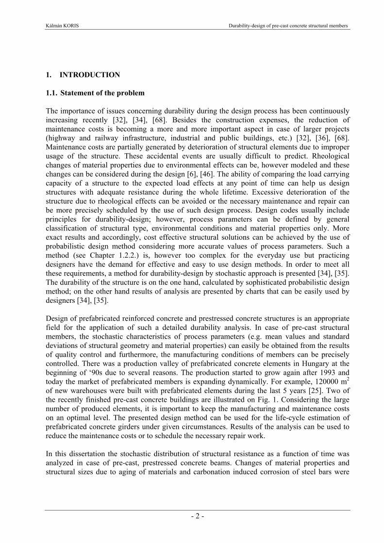
1. INTRODUCTION 1.1. Statement of the problem The importance of issues concerning durability during the design process has been continuously increasing recently [32], [34], [68]. Besides the construction expenses, the reduction of maintenance costs is becoming a more and more important aspect in case of larger projects (highway and railway infrastructure, industrial and public buildings, etc.) [32], [36], [68]. Maintenance costs are partially generated by deterioration of structural elements due to improper usage of the structure. These accidental events are usually difficult to predict. Rheological changes of material properties due to environmental effects can be, however modeled and these changes can be considered during the design [6], [46]. The ability of comparing the load carrying capacity of a structure to the expected load effects at any point of time can help us design structures with adequate resistance during the whole lifetime. Excessive deterioration of the structure due to rheological effects can be avoided or the necessary maintenance and repair can be more precisely scheduled by the use of such design process. Design codes usually include principles for durability-design; however, process parameters can be defined by general classification of structural type, environmental conditions and material properties only. More exact results and accordingly, cost effective structural solutions can be achieved by the use of probabilistic design method considering more accurate values of process parameters. Such a method (see Chapter 1.2.2.) is, however too complex for the everyday use but practicing designers have the demand for effective and easy to use design methods. In order to meet all these requirements, a method for durability-design by stochastic approach is presented [34], [35]. The durability of the structure is on the one hand, calculated by sophisticated probabilistic design method; on the other hand results of analysis are presented by charts that can be easily used by designers [34], [35]. Design of prefabricated reinforced concrete and prestressed concrete structures is an appropriate field for the application of such a detailed durability analysis. In case of pre-cast structural members, the stochastic characteristics of process parameters (e.g. mean values and standard deviations of structural geometry and material properties) can easily be obtained from the results of quality control and furthermore, the manufacturing conditions of members can be precisely controlled. There was a production valley of prefabricated concrete elements in Hungary at the beginning of ‘90s due to several reasons. The production started to grow again after 1993 and today the market of prefabricated members is expanding dynamically. For example, 120000 m2 of new warehouses were built with prefabricated elements during the last 5 years [25]. Two of the recently finished pre-cast concrete buildings are illustrated on Fig. 1. Considering the large number of produced elements, it is important to keep the manufacturing and maintenance costs on an optimal level. The presented design method can be used for the life-cycle estimation of prefabricated concrete girders under given circumstances. Results of the analysis can be used to reduce the maintenance costs or to schedule the necessary repair work. In this dissertation the stochastic distribution of structural resistance as a function of time was analyzed in case of pre-cast, prestressed concrete beams. Changes of material properties and structural sizes due to aging of materials and carbonation induced corrosion of steel bars were

Kálmán KORIS Durability-design of pre-cast concrete structural members
- 3 -
considered during the analysis. Stochastic parameters of structural resistance were calculated by stochastic finite element method (SFEM). The implemented method was used to create design charts for prestressed beams. The probability of failure as a function of time is presented on these charts. They can be used for easy and effective life-cycle design of pre-cast members [34], [35].
Airport maintenance base, Ferihegy Shopping center in Nyíregyháza
Fig. 1. Recently finished buildings made of prefabricated concrete members 1.2. Probabilistic methods in structural engineering 1.2.1. Historical review Probabilistic methods in engineering practice were first applied in the field of hydrology. Mathematical statistics was later also used by transportation engineers and finally structural engineers started to use probabilistic approach for the design. A. M. Freudenthal was the first person to evaluate a safety factor by stochastic approach for the design of airplanes. However, the allowed level of risk was still not defined for the calculations. Kazinczy was the first Hungarian engineer who introduced a probabilistic method for structural design in 1942. He used normal distribution for the evaluation of the probability of failure and tried to maximize the takings of the structure. Up to date probabilistic methods in structural engineering include several analytical and numerical methods as described below. 1.2.2. Analytical methods If we consider non-linear response of the structure under static loads, the available analytical methods are the following:
- General solution of the response equation - Second-moment analysis - Stochastic finite element method (SFEM) - Simplified use of extremum principles
Kálmán KORIS Durability-design of pre-cast concrete structural members
- 4 -
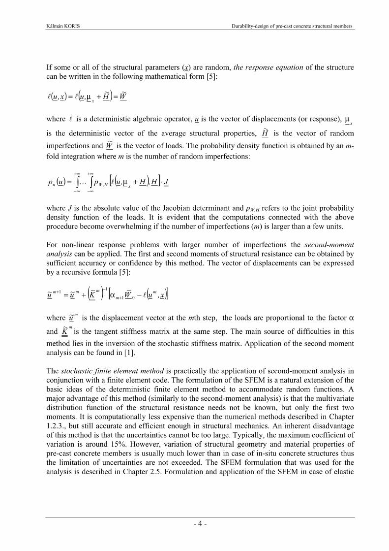
If some or all of the structural parameters (x) are random, the response equation of the structure can be written in the following mathematical form [5]:
( ) ( ) W~H~,ux,ux
=+μ= ll where l is a deterministic algebraic operator, u is the vector of displacements (or response),
xμ
is the deterministic vector of the average structural properties, H~ is the vector of random imperfections and W~ is the vector of loads. The probability density function is obtained by an m-fold integration where m is the number of random imperfections:
( ) ( )[ ]∫ ∫+∞
∞−
+∞
∞−
⋅+μ= JH,H,upupxH,Wu lK
where J is the absolute value of the Jacobian determinant and pW,H refers to the joint probability density function of the loads. It is evident that the computations connected with the above procedure become overwhelming if the number of imperfections (m) is larger than a few units. For non-linear response problems with larger number of imperfections the second-moment analysis can be applied. The first and second moments of structural resistance can be obtained by sufficient accuracy or confidence by this method. The vector of displacements can be expressed by a recursive formula [5]:
( ) ( )[ ]x,uW~K~u~u~ mm
mmml−α+= +
−+01
11 where mu~ is the displacement vector at the mth step, the loads are proportional to the factor α
and m
K~ is the tangent stiffness matrix at the same step. The main source of difficulties in this method lies in the inversion of the stochastic stiffness matrix. Application of the second moment analysis can be found in [1]. The stochastic finite element method is practically the application of second-moment analysis in conjunction with a finite element code. The formulation of the SFEM is a natural extension of the basic ideas of the deterministic finite element method to accommodate random functions. A major advantage of this method (similarly to the second-moment analysis) is that the multivariate distribution function of the structural resistance needs not be known, but only the first two moments. It is computationally less expensive than the numerical methods described in Chapter 1.2.3., but still accurate and efficient enough in structural mechanics. An inherent disadvantage of this method is that the uncertainties cannot be too large. Typically, the maximum coefficient of variation is around 15%. However, variation of structural geometry and material properties of pre-cast concrete members is usually much lower than in case of in-situ concrete structures thus the limitation of uncertainties are not exceeded. The SFEM formulation that was used for the analysis is described in Chapter 2.5. Formulation and application of the SFEM in case of elastic

Kálmán KORIS Durability-design of pre-cast concrete structural members
- 5 -
or plastic materials can be found in [7], [13], [14], [15], [16], [23], [24], [42], [51], [58], [69] and [70] while the brittle fracture reliability analysis is explained in [9]. In the framework of probabilistic structural analysis, extremum principles furnish procedures for calculating the probability that the response vector u falls in some special subset of the set of possible responses. The lower bound to the probability of successful performance can be expressed as [5]:
( ) ( ) jjmm PuobPruobPr ≥Φ∈≥∈ l where Φj is a possible region for responses and Pj is a given probability for the actual region. The method of extremum principles can be used for example to evaluate plastic deformations of structures with random yield strength or to obtain the bounds of the collapse load of rigid-plastic random strength structures. 1.2.3. Numerical methods Analytical solution procedures are either unavailable or inefficient for many structural engineering problems with random variables or functions (including non-linear problems, dynamic analyses and damage accumulation problems). These engineering problems can be solved by one of the available numerical methods:
- Monte-Carlo simulation - Special Monte-Carlo techniques
Stratified sampling Correlated sampling Importance sampling
- Hybrid simulation procedures Monte-Carlo simulation is a numerical method for solving mathematical problems by the modeling of random quantities [57]. This simulation method essentially assumes that the statistics of the input random quantities are known. Each experiment consists of a set of input quantities provided by random number generator according to the given statistics. A deterministic structural analysis is performed on these quantities to obtain a set of output (response) quantities. The experiment is repeated n times and the response statistics are finally calculated from the sample of responses. The advantage of this method is that it can be practically applied in case of any engineering problem with existing deterministic solution. However, the variance of the estimate is in inverse proportion to the number of experiments (n):
( ) ( )22 1
xgxgm sn
s =
where ( )xgms 2 is the variance of the estimate and ( )
2xgs is the variance of input quantities. It means
that accurate solution can be achieved by higher number of experiments (n) only. In case of complex structures, this can be too time-consuming. The Monte-Carlo simulation is used in

Kálmán KORIS Durability-design of pre-cast concrete structural members
- 6 -
Chapter 4.1.2. to evaluate the resistance of a prestressed concrete beam on cross-sectional level. Application of the Monte-Carlo simulation for concrete structures can also be found in [2], [9], [28], [30], [53]. As the computational effort is proportional to the numbers of experiments (n), special Monte-Carlo simulation techniques can be used to reduce the variance of the estimate in case of lower values of n [5]. In case of stratified sampling the range of the random variables is divided into conveniently chosen class intervals and it is assumed that the probabilities associated with the class intervals are known a priori. The sample values are usually stochastically independent in case of Monte-Carlo simulation. However, if these values are correlated, the variance of estimate can be reduced by using the method of correlated samples. The method of importance sampling attempts to estimate the response statistics by the sample average. Hybrid simulation makes use of simulation techniques only to yield samples of structural responses whose size is selected to ensure good accuracy on the estimation of the central values of the quantities of interest [5]. In this case, analytical model can be used to translate statistical information into probabilistic statements and reliability evaluations. Hybrid simulation can, for example, be used for the simulation of damage accumulation under a sequence of independent pulses (e.g. traffic loads on a bridge). 1.2.4. Literature of the probabilistic analysis of concrete structures The probabilistic analysis of structures has an extensive literature, however, many of these contributions deal with the mathematical formulation and solution of the problem only. Numerical example to the calculation of structures by probabilistic approach can be found much less frequently. Some contributions to this topic are listed in Tab. 1. K. Handa and K. Andersson analyzed a steel cantilever beam and a wooden roof truss by stochastic finite element method (SFEM), considering the variation of applied load, moment of inertia and Young’s modulus [24]. J. Almási proposed a probabilistic method for the analysis of reinforced and prestressed concrete structures combining finite element method (FEM) with Monte-Carlo simulation (MCS). He considered random structural geometry and material properties as well as non-linear behavior of materials and steel to concrete interaction [3]. W. K. Liu and T. Belytschko used SFEM for the analysis of a cantilever beam subjected to large deflection. They considered Saint Venant-Kirchoff model for nonlinear elasticity, random load, random Young’s modulus as well as random cross-sectional height [42]. G. Dasgupta and S. Yip calculated a cantilever beam by SFEM considering randomness of Young’s modulus [14]. G. H. Besterfield, W. K. Liu and M. A. Lawrence analyzed brittle fracture reliability of a concrete beam (without reinforcement) by SFEM. Young’s modulus, applied load and crack length were considered as random quantities [9]. G. Deodatis examined the bounds on response variability in case of a three-bay frame by SFEM considering random elastic modulus and structural geometry [15]. J. G. Teigen, D. M. Frangopol, S. Sture and C. A. Felippa calculated a simply supported beam by SFEM considering random loads and material properties as well as non-linear material characteristics [58]. S. E. Ruiz and J. C. Aguilar examined the reliability of short and slender reinforced concrete columns by MCS. They applied non-linear material behaviour, random geometry, material properties and loads during the analysis [53]. J. Eibl and B. Schmidth-Hurtienne demonstrated the use of SFEM on a two-span reinforced concrete beam and on a reinforced column [18]. They considered
Kálmán KORIS Durability-design of pre-cast concrete structural members
- 7 -
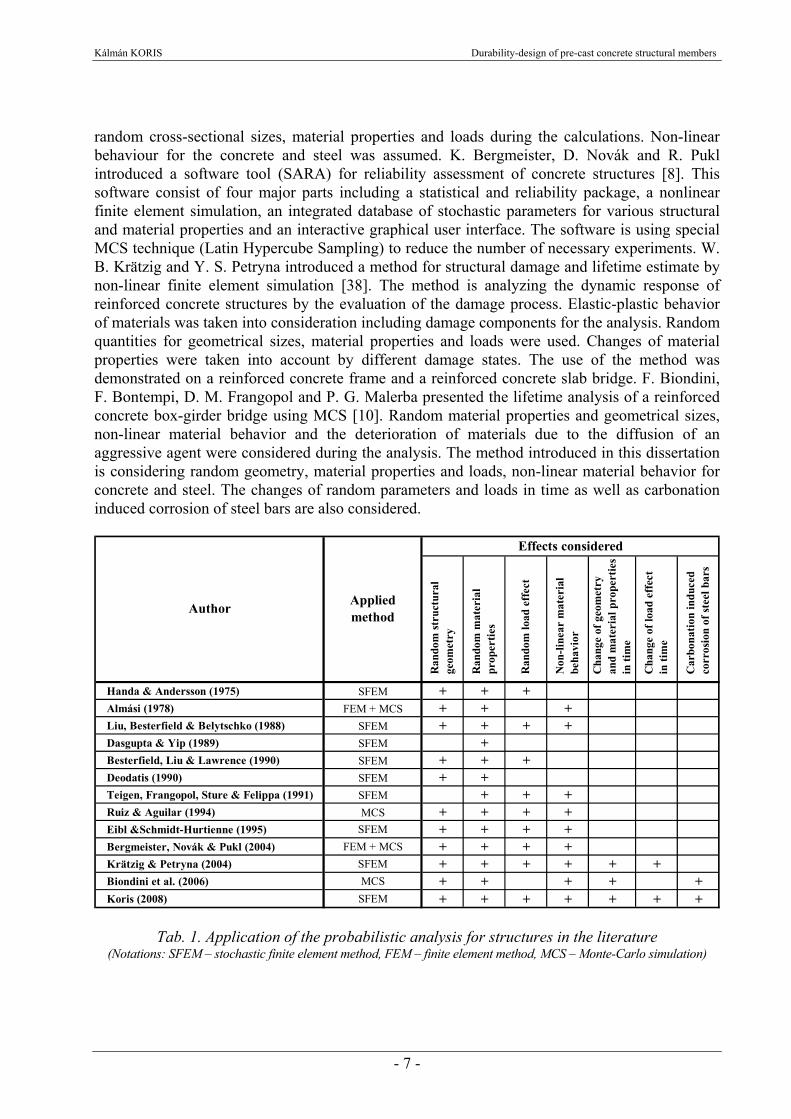
random cross-sectional sizes, material properties and loads during the calculations. Non-linear behaviour for the concrete and steel was assumed. K. Bergmeister, D. Novák and R. Pukl introduced a software tool (SARA) for reliability assessment of concrete structures [8]. This software consist of four major parts including a statistical and reliability package, a nonlinear finite element simulation, an integrated database of stochastic parameters for various structural and material properties and an interactive graphical user interface. The software is using special MCS technique (Latin Hypercube Sampling) to reduce the number of necessary experiments. W. B. Krätzig and Y. S. Petryna introduced a method for structural damage and lifetime estimate by non-linear finite element simulation [38]. The method is analyzing the dynamic response of reinforced concrete structures by the evaluation of the damage process. Elastic-plastic behavior of materials was taken into consideration including damage components for the analysis. Random quantities for geometrical sizes, material properties and loads were used. Changes of material properties were taken into account by different damage states. The use of the method was demonstrated on a reinforced concrete frame and a reinforced concrete slab bridge. F. Biondini, F. Bontempi, D. M. Frangopol and P. G. Malerba presented the lifetime analysis of a reinforced concrete box-girder bridge using MCS [10]. Random material properties and geometrical sizes, non-linear material behavior and the deterioration of materials due to the diffusion of an aggressive agent were considered during the analysis. The method introduced in this dissertation is considering random geometry, material properties and loads, non-linear material behavior for concrete and steel. The changes of random parameters and loads in time as well as carbonation induced corrosion of steel bars are also considered.
Ran
dom
stru
ctur
al
geom
etry
Ran
dom
mat
eria
l pr
oper
ties
Ran
dom
load
eff
ect
Non
-line
ar m
ater
ial
beha
vior
Cha
nge
of g
eom
etry
and
mat
eria
l pro
pert
ies
in ti
me
Cha
nge
of lo
ad e
ffec
tin
tim
e
Car
bona
tion
indu
ced
corr
osio
n of
stee
l bar
sHanda & Andersson (1975) SFEM + + +Almási (1978) FEM + MCS + + +Liu, Besterfield & Belytschko (1988) SFEM + + + +Dasgupta & Yip (1989) SFEM +Besterfield, Liu & Lawrence (1990) SFEM + + +Deodatis (1990) SFEM + +Teigen, Frangopol, Sture & Felippa (1991) SFEM + + +Ruiz & Aguilar (1994) MCS + + + +Eibl &Schmidt-Hurtienne (1995) SFEM + + + +Bergmeister, Novák & Pukl (2004) FEM + MCS + + + +Krätzig & Petryna (2004) SFEM + + + + + +Biondini et al. (2006) MCS + + + + +Koris (2008) SFEM + + + + + + +
AppliedmethodAuthor
Effects considered
Tab. 1. Application of the probabilistic analysis for structures in the literature (Notations: SFEM – stochastic finite element method, FEM – finite element method, MCS – Monte-Carlo simulation)

Kálmán KORIS Durability-design of pre-cast concrete structural members
- 8 -
2. PROBABILISTIC APPROACH FOR THE DURABILITY-DESIGN The durability of a structural member is satisfactory if the probability of failure does not exceed a certain value during the lifetime. Failure of the structure can be defined by different limit states such as ultimate or serviceability limit state. The probability of reaching such a limit state is the function of different stochastic parameters and the values of these parameters are changing in time due to the deterioration of materials. The purpose is to predict the value of process parameters in any given point of time and to evaluate the probability of failure using the appropriate quantities. The adequacy of the structure can be decided by the comparison of calculated and expected probability of failure. A possible way for the determination of expected probability of failure is presented in Chapter 2.2. 2.1. Definition of the probability of failure The ability of a structure to resist the acting loads can be described by a G performance function. This function can be usually written as [12]: G = R - S where structural resistance (R) and the loads (S) are deterministic functions of certain parameters. At a positive value of G the structure is functioning properly, a negative value refers to structural failure and in case of G = 0 the structure is in ultimate limit state. Load carrying capacity of a structure and the acting loads are probabilistic values, thus the G performance function will be a probabilistic value too and it can be described by an FG distribution function. Assuming that the parameters of the distribution are known, the probability of failure (pG) can be calculated as [39], [49], [52]:
∫∞−
=0
dG)G(fpG
where f(G) is the probability density function of G. In case of engineering structures, the system is usually too complex thus we are not able to evaluate the probability of failure by one performance function. The system must be decomposed to smaller subsystems, the performance functions of the subsystems must be calculated separately and the failure of the structure can be evaluated by the combination of these separate performance functions. The combination depends on the type of the system. We can distinguish serial, parallel and mixed systems. In case of serial systems the failure event will be the union of subset failure events while for parallel systems the product of the subset failure events must be used. However, in case of buildings and other structures, these subsystems are statistically not independent, thus the application of the above method could be difficult. A possible solution for such systems is the geometrical approach, where we use the geometry of the range of integration [40]. In this case the G performance function can be written as linear function of xi normally distributed random variables:
xccxcxcxccG Tnn +=++++= 022110 K
Kálmán KORIS Durability-design of pre-cast concrete structural members
- 9 -
It is assumed that Mx and sx are the mean value and standard deviation of the xi variable, ρij is the coefficient of correlation between xi and xj as well as MG and sG are the mean value and standard deviation of G performance function. Let us standardize the xi random variables so we get:
( )xT MxTLr −⋅⋅= −1
where L is a diagonal matrix composed from the eigenvalues of the covariance matrix and columns of matrix T are the eigenvectors of covariance matrix. Using the standardized variables (r), the performance function can be written as:
( )xT MrLTccG +⋅⋅+= 0
With the use of standardized variables, the G = 0 ultimate limit state defines a hypersurface of n-1 dimensions in a space of n dimensions. The closest point of this surface to the origin of coordinates means the failure of highest probability. The minimum distance between the origin and the hypersurface is [40]:
β==⋅⋅⋅⋅⋅
+
G
G
TT
xT
sM
cTLLTc
Mcc0
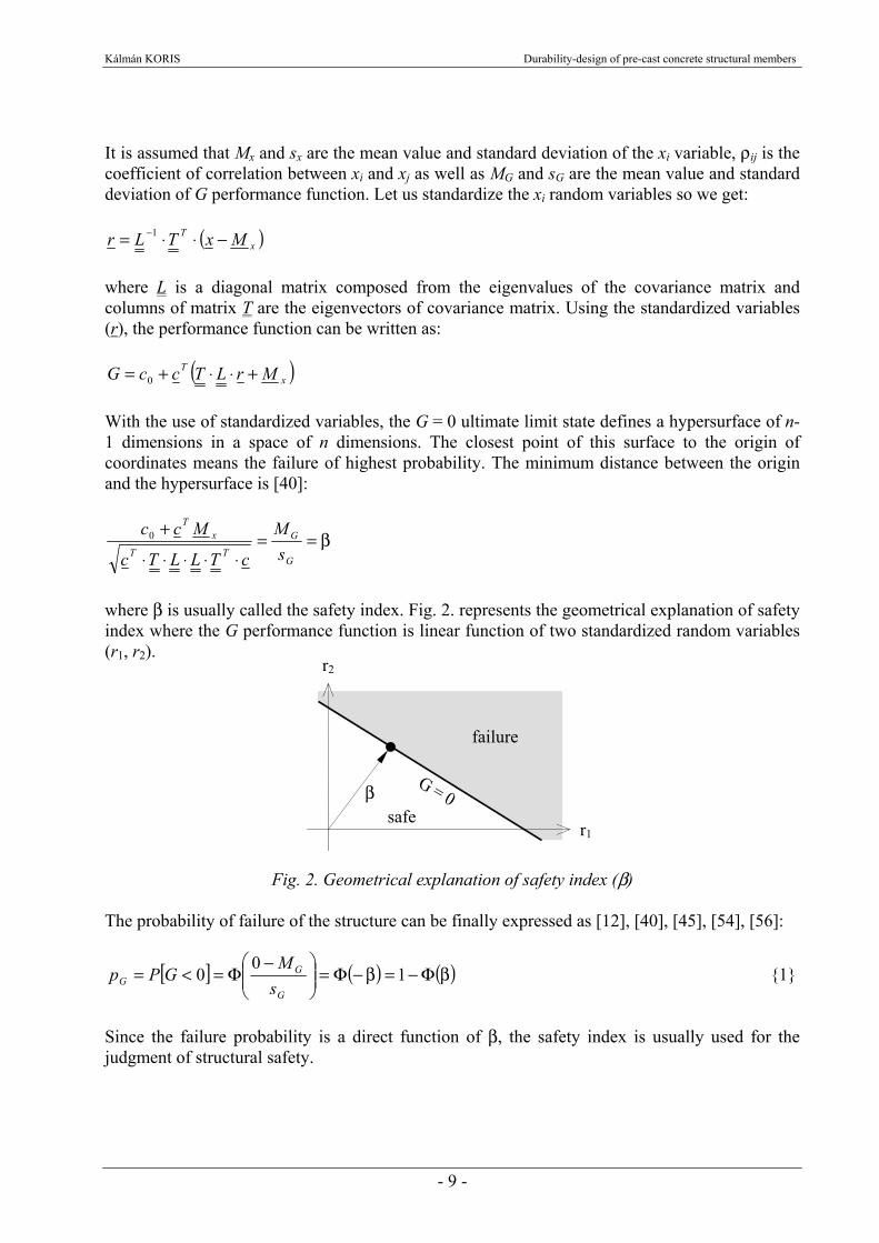
where β is usually called the safety index. Fig. 2. represents the geometrical explanation of safety index where the G performance function is linear function of two standardized random variables (r1, r2).
Fig. 2. Geometrical explanation of safety index (β) The probability of failure of the structure can be finally expressed as [12], [40], [45], [54], [56]:
[ ] ( ) ( )βΦ−=β−Φ=⎟⎟⎠
⎞⎜⎜⎝
⎛ −Φ=<= 1
00
G
GG s
MGPp {1}
Since the failure probability is a direct function of β, the safety index is usually used for the judgment of structural safety.
r2
β
failure
r1safe
Kálmán KORIS Durability-design of pre-cast concrete structural members
- 10 -
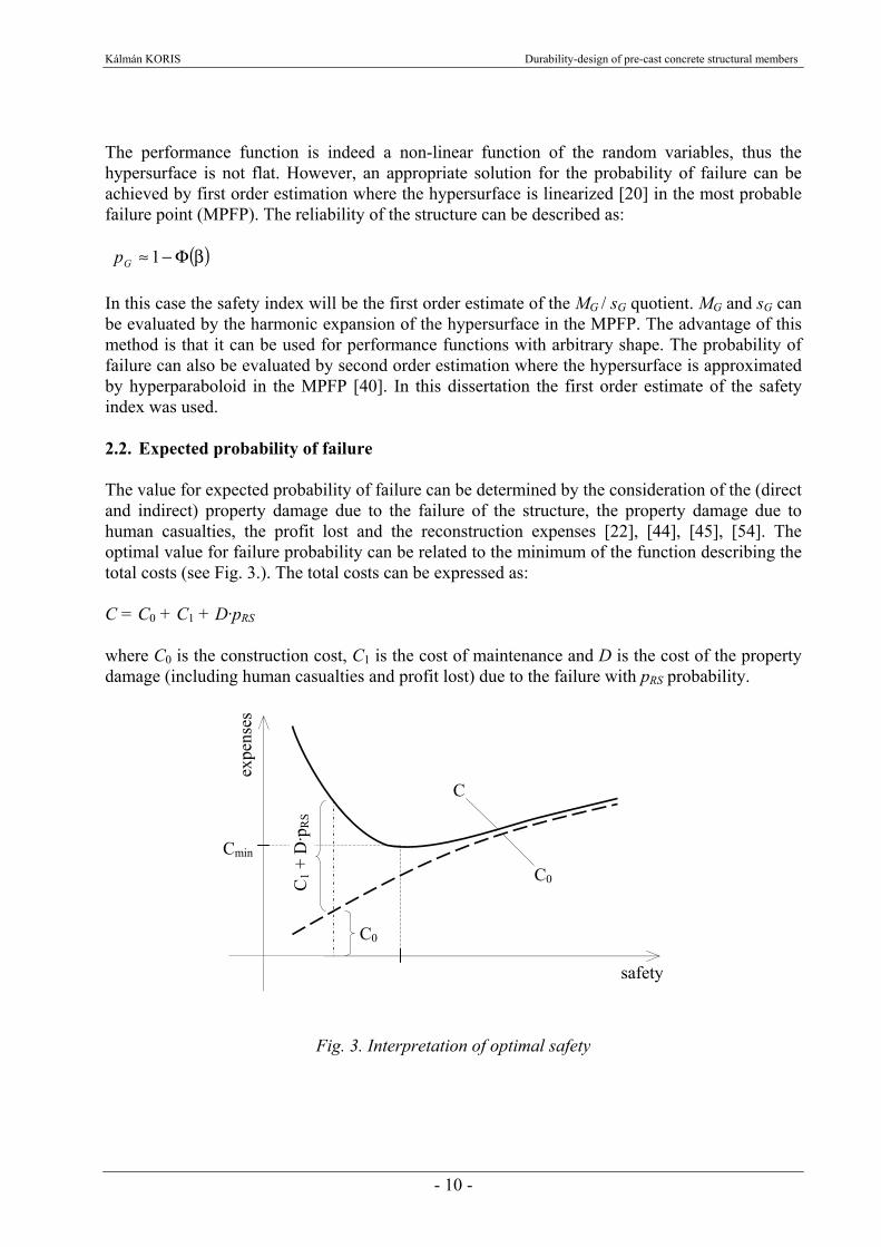
The performance function is indeed a non-linear function of the random variables, thus the hypersurface is not flat. However, an appropriate solution for the probability of failure can be achieved by first order estimation where the hypersurface is linearized [20] in the most probable failure point (MPFP). The reliability of the structure can be described as: ( )βΦ−≈ 1Gp In this case the safety index will be the first order estimate of the MG / sG quotient. MG and sG can be evaluated by the harmonic expansion of the hypersurface in the MPFP. The advantage of this method is that it can be used for performance functions with arbitrary shape. The probability of failure can also be evaluated by second order estimation where the hypersurface is approximated by hyperparaboloid in the MPFP [40]. In this dissertation the first order estimate of the safety index was used. 2.2. Expected probability of failure The value for expected probability of failure can be determined by the consideration of the (direct and indirect) property damage due to the failure of the structure, the property damage due to human casualties, the profit lost and the reconstruction expenses [22], [44], [45], [54]. The optimal value for failure probability can be related to the minimum of the function describing the total costs (see Fig. 3.). The total costs can be expressed as: C = C0 + C1 + D·pRS where C0 is the construction cost, C1 is the cost of maintenance and D is the cost of the property damage (including human casualties and profit lost) due to the failure with pRS probability.
Fig. 3. Interpretation of optimal safety
expe
nses
C
safety
C0 Cmin
C0
C1 +
D·p
RS

Kálmán KORIS Durability-design of pre-cast concrete structural members
- 11 -
The optimum value of the expected failure probability considering human casualties was first defined by Tamás Kármán in 1964 as [22], [55], [56]:
δ⋅=
bpopt
1 {2}
where δ = D/C0 is the damage ratio and b is the coefficient considering the type of structural material, terms of use and the type of analysis method. The values δ = 125 and b = 80 are typical for building constructions. Substituting these values into {2} the optimum value of the expected failure probability is popt = 10-4. It is worthy of note that Eurocode uses the same value as the level for desired risk for structures. 2.3. Evaluation of the probability of failure According to {1} the failure probability can be calculated by means of the first two parameters (MG, sG) of the G performance function [39], [45], [56]. These parameters can be calculated from the distributions of structural resistance and acting loads. In case of structural resistance, first two parameters of the distribution can only be evaluated by the stochastic finite element method and therefore skewness is neglected [4]. Mean value of the G performance function can be calculated from: MG(t) = MR(t) – MS(t) where MR(t) and MS(t) are mean values of structural resistance and acting loads as a function of time (t) respectively. Standard deviation of G can be evaluated by the Gaussian law of error distribution [49], [52]:
( ) ( ) ( )22 tststs RRG += where sR(t) and sS(t) are the standard deviations of structural resistance and acting loads at time point t respectively. Mean value and standard deviation of structural resistance were calculated by SFEM in function of time while the distribution of load effect was assumed by [45] (see also Chapter 3.2.5.). Change of these distributions in time is presented on Fig. 4. Normal distribution can be assumed for the resistance of G performance function and thus the probability of failure of a given pre-cast structural member can be calculated in a desired point of time (t) from [49], [52]:
( )( )
( )( )( ) dxe
tstp
xtstMx
GG
G
G
∫∞−
⋅−
−
⋅⋅π
=2
2
2
21 {3}

Kálmán KORIS Durability-design of pre-cast concrete structural members
- 12 -
Fig. 4. Change of the distributions of structural resistance and load effect in time
Adequacy of the structure can be decided by the comparison of the probability of failure pG(t) and the expected value of failure probability popt. The structural resistance is adequate against the acting loads if the following equation is satisfied: pG (T) ≤ popt where T is the expected life-span. The calculation method of expected life-span (or optimal life-span) in case of different structures can be for example found in [48]. can be It is important to mention that the value of popt is usually decreasing in time. However the use of a constant popt value, that is valid at the end of the life-span, is satisfactory in practical cases. 2.4. Evaluation of the mean value of structural resistance Mean value of the analyzed prestressed concrete beams were determined by finite element method considering non-linear behavior of materials [17], [19]. 2.4.1. Application of finite element method The finite element method [11] was used to analyze simply supported beam subjected to bending and compression. Mean values of input parameters (structural geometry, material properties) were used for the analysis. Deformation of the beam can be calculated from the equation [11]:
quK = {4} where K is the stiffness matrix of the structure, q is the vector of external loads and u is the vector of unknown nodal displacements. The stiffness matrix of the structure can be compiled from the stiffness matrices of individual elements considering the support conditions. The stiffness matrix of a single element for beams can be calculated from the following expression:
P P
load
eff
ect
resi
stan
ce
time t1 t2
R(t1) R(t2)
S(t1) S(t2)
Kálmán KORIS Durability-design of pre-cast concrete structural members
- 13 -
dxBDBKL
Te ∫=
where B is the product of the operator matrix (L) and the interpolation matrix (N) while D is the matrix describing the connection between internal forces and deformations. Shear deformations were neglected in the calculation since they are significantly lower than the flexural deformations in case of reinforced concrete. Another reason for neglecting shear deformations was that failure of the structure due to shear force was not considered during the analysis. The operator matrix of a beam without shear deflections can be written as:
⎥⎥⎥⎥⎥⎥
⎦
⎤
⎢⎢⎢⎢⎢⎢
⎣
⎡
−
=
2
2
2
2
00
00
00
dxd
dxd
dxd
L
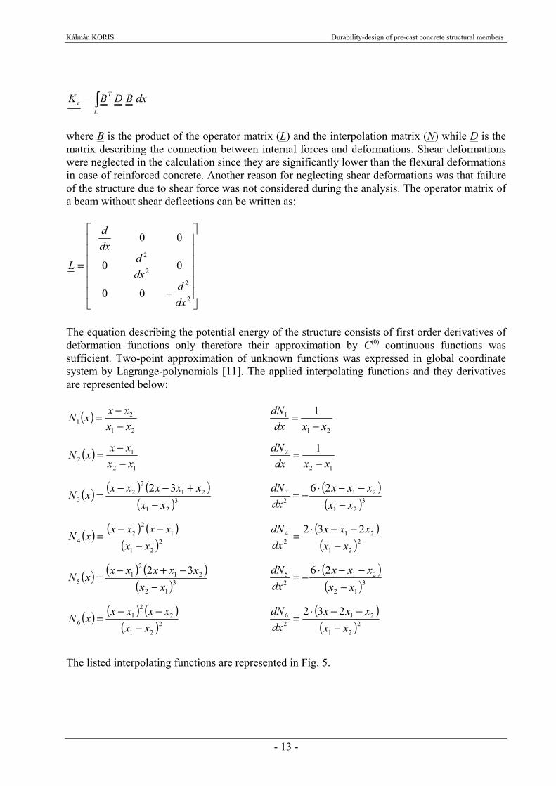
The equation describing the potential energy of the structure consists of first order derivatives of deformation functions only therefore their approximation by C(0) continuous functions was sufficient. Two-point approximation of unknown functions was expressed in global coordinate system by Lagrange-polynomials [11]. The applied interpolating functions and they derivatives are represented below:
( )21
21 xx
xxxN−−=
21
1 1xxdx
dN−
=
( )12
12 xx
xxxN−−=
12
2 1xxdx
dN−
=
( ) ( ) ( )( )3
21
212
23
32xx
xxxxxxN−
+−−= ( )( )3
21
2123 26
xxxxx
dxdN
−−−⋅−=
( ) ( ) ( )( )2
21
12
24 xx
xxxxxN−
−−= ( )( )2
21
2124 232
xxxxx
dxdN
−−−⋅=
( ) ( ) ( )( )3
12
212
15
32xx
xxxxxxN−
−+−= ( )( )3
12
2125 26
xxxxx
dxdN
−−−⋅−=
( ) ( ) ( )( )2
21
22
16 xx
xxxxxN−
−−= ( )( )2
21
2126 232
xxxxx
dxdN
−−−⋅=
The listed interpolating functions are represented in Fig. 5.

Kálmán KORIS Durability-design of pre-cast concrete structural members
- 14 -
Fig. 5. The applied interpolating Lagrange-polynomials Using the Lagrange-polynomials described above, the interpolating matrix can be expressed as:
⎥⎥⎥
⎦
⎤
⎢⎢⎢
⎣
⎡
−−=
6543
6543
21
00000000000000000000
NNNNNNNN
NNN
2.4.2. Non-linear behavior of reinforced and prestressed concrete While no forming of cracks has occurred in the concrete, the material can be considered homogenous and isotropic. Due to the low level of stresses, linear stress-strain relationship can be used. The stiffness matrix of a finite element holds elastic cross-sectional properties, resulting in a linear connection between forces and deformations. In case of beams subjected to bending and compression, this connection can be expressed in the following form:
ε=⎥⎥⎥
⎦
⎤
⎢⎢⎢
⎣
⎡
κκε
⋅⎥⎥⎥
⎦
⎤
⎢⎢⎢
⎣
⎡
⋅⋅
⋅=
⎥⎥⎥
⎦
⎤
⎢⎢⎢
⎣
⎡
=σ DIE
IEAE
MMN
y
x
y
x
y
x
000000
where N is the axial force, Mx and My are the bending moments acting in different directions, E·A is the axial stiffness, E·Ix and E·Iy are the flexural stiffnesses, ε is the value of compression strain and κx and κy are the curvature in vertical and horizontal plains. After the formation of cracks in concrete, the problem cannot be handled with assumption of plane state of stress. Stiffness of the structure significantly decreases, the material properties, such as Young modulus, shear modulus, Poisson's ratio, etc. cannot be interpreted. A given kind of unit deformation will be affected by all kinds of stresses, thus the stiffness properties will depend on the acting forces [17]. It means that the D matrix contains elements also outside its principal diagonal. After the formation of cracks, D can be generally written in the following way:
x1 x2
N11
x1 x2
N2 1
x1 x2
N3-1
x1 x2
N5-1
x1 x2
N4
x1 x2
N6
1

Kálmán KORIS Durability-design of pre-cast concrete structural members
- 15 -
ε=⎥⎥⎥
⎦
⎤
⎢⎢⎢
⎣
⎡
κκε
⋅⎥⎥⎥
⎦
⎤
⎢⎢⎢
⎣
⎡
=⎥⎥⎥
⎦
⎤
⎢⎢⎢
⎣
⎡
=σ DKKKKKKKKK
MMN
y
x
MyMyMyMxMyN
MxMyMxMxMxN
NMyNMxNN
y
x
Stiffness values (Kij) in the D matrix are not constant anymore, they depend on the values of internal forces (N, Mx, My) thus D matrix will be a function of the vector of internal forces (σ). In case of non-linear material behavior, the stiffness values included in D matrix are usually too difficult to be evaluated directly. Under these conditions, deformations can be calculated using the method of increments. During the analysis the load was increased in steps and for each load increment, the chord of the stiffness matrix (Fig. 6.) was evaluated and used.
Fig. 6. Interpretation of bending stiffness before and after forming of cracks The matrix describing the connection between internal forces and deformations for a given load level was evaluated using the internal forces (N, Mx, My). These forces were evaluated by stiffness values corresponding to the previous load level. The bending moment-curvature relationship of the given prestressed concrete cross-section was used to calculate current values of deformations (ε, κx, κy). The D matrix was expressed using these deformations:
⎥⎥⎥
⎦
⎤
⎢⎢⎢
⎣
⎡
κκ
ε=
yy
xx
/M/M
/ND
000000
{5}
A single-parameter load was applied during the analysis (Fig. 7.) that is the load was expressed as product of the load-intensity (F) and a load-distribution vector (Φ). The value of the load-intensity was increased in steps until structural failure. The chord of the stiffness matrix was calculated according to {5} for each load increment. Using mean values of input parameters, the highest level of applicable load without structural failure was considered as the mean value of structural resistance. Failure of the structure was specified by a Π damage indicator. The value of damage indicator can be appropriately defined by the following expression [38]:
M
κ
K=E·I
M
κ
κ= M
chK
form
ing
of
crac
ks
Uncracked cross-section Cracked cross-section

Kálmán KORIS Durability-design of pre-cast concrete structural members
- 16 -
undamaged
damaged
λλ
−=Π 1
where λdamaged is the eigenvalue of the stiffness matrix in case of structural damage while λundamaged refers to the eigenvalue of current stiffness matrix at a given load level. Failure of the structure occurs in case of Π ≤ 0.
Fig. 7. Scheme for single-parameter loading of the structure 2.4.3. Evaluation of the bending moment-curvature diagrams The bending moment-curvature diagram of a given prestressed concrete cross-section was evaluated according to the principles in [21], [26], [29], [33], [41] and [56]. Fig. 8. represents the stress-strain relations of materials [21] that were used during the calculation.
Fig. 8. Stress-strain relation for concrete (a), steel bars (b) and prestressing tendons (c)
The cross-section of pre-cast, prestressed concrete beams is usually not rectangular but rather “T” or “I” shaped for more efficient use of concrete. For this reason, the width of the cross-section was defined as a function of the distance (ξ) from the top of the section as b = b(ξ). While no
load-intensity (F)
Fi = F·Φi
σc
εc
fc
εcu εcl fct εct
a.)
εs
fy
εsu
Es
σs compression and tension
εsy
b.)
εp
fp
εpu
σp
εpy
Ep
compression and tension
c.)

Kálmán KORIS Durability-design of pre-cast concrete structural members
- 17 -
forming of cracks occurred, the bending moment in the cross-section was considered to be proportional to the curvature as: MI(κ) = κ·Ec·Ix + Mp where Ec is the coefficient of elasticity for concrete, Ix is the inertia of the cross-section and Mp is the bending moment due to effective prestressing force. After forming of cracks the internal forces acting in the concrete were calculated by numerical integration over the appropriate part of the cross-section. The position of neutral axis (x) in case of a given value of curvature (κ) was calculated from the equilibrium of external and internal forces:
( ) ( ) ( ) ( ) ( ) ( ) pmptppcpstsscs
h
c NA,xA,xA,xA,xdb,,xc
=⋅κσ−⋅κσ−⋅κσ−⋅κσ+ξξ⋅ξκσ∫0
where σc, σs and σp are the stresses in the concrete, steel bars and prestressing tendons according to given stress-strain curves, Asc and Ast are the cross-sectional areas of compressed and tensioned steel bars, Apc and Apt are the cross-sectional areas of “compressed” and tensioned tendons respectively, Npm is the effective prestressing force and hc = x + εct / κ is the height of working concrete zone. The bending moment M(κ) with respect to the given κ curvature can be evaluated from the equilibrium of external and internal bending moments.
( ) ( ) ( ) ( ) ( ) ∑∑∫ −⋅+−⋅+ξξ−⋅ξ⋅κσ=κj
pipji
sisi
h
cII xdFxdFdxb,xMc
0
where Fsi is the force acting in compressed or tensioned steel bars, Fpi is the force acting in “compressed” or tensioned tendons, dsi and dpi are the effective height of cross-section with respect to steel bars and tendons. Bending moment-curvature diagrams of different cross-sections are presented in Fig. 25., Fig. 44. and Fig. 56. 2.5. Evaluation of scatter of structural resistance by stochastic finite element method 2.5.1. The variational approach Material properties and geometrical sizes of a pre-cast member are fluctuating around an expected value (Mx) due to inhomogeneousity of materials and errors in manufacturing. These fluctuations can be described by a continuous random variable. Scatter of these input parameters (x) can be described by the continuous random variable α(ζ) as: x = Mx·[1+α(ζ)] The continuous α(ζ) function can be discretized along the finite elements by the use of stochastic finite element method (see Fig. 9.). The α(ζ) function can be approximated by the interpolation functions (Ni) for any given finite element:

Kálmán KORIS Durability-design of pre-cast concrete structural members
- 18 -
( ) ( ) ( ) 101
≤ξ≤α⋅ξ=α ∑=
n
i
kii
k ,N
It is reasonable to assume a constant shape for the approximate α(k) function within separate elements (Ni(ξ) = 1) so the probabilistic degree of freedom of the system will be equal to the number of finite elements. The random variable for a given element can be written as: α(k) = ( )k
iα⋅1 = αk Discretization of a continuous α(ζ) random variable is presented on Fig. 9.
Fig. 9. Discretization of a continuous α(ζ) random variable The covariance of the structural resistance can be expressed by the covariance of input parameters by using the SFEM. The covariance (Cx) of a given random input parameter (x) can be written in the following form [18], [24]:
Txxx sCsC ⋅⋅= ρ {6}
where xs includes the values of standard deviations along the principal diagonal and ρC is the
correlation matrix. The correlation between different elements can be described by an exponentially decaying function of the distance between two elements and the length of correlation. The value of correlation between the elements number i and j can be evaluated from:
ρi,j = λζΔ
− j,i
e
αk
lk α
ξ·lk ζ
α(ζ)
ζ
α(ζi)
Kálmán KORIS Durability-design of pre-cast concrete structural members
- 19 -
where Δζi,j is the distance between the centre point of the elements and λ is the length of correlation. It was assumed during the analysis that random variables are correlated along the span of the beams so the correlation length was equal to the span. If the vector of external loads ( q ) is a function of an x random parameter with a standard
deviation of sx, its standard deviation can be approximately expressed by the first term of Taylor’s series [18], [23], [34], [35]:
xq sx
qs ⋅
∂
∂= {7}
Substituting {7} into {6} the covariance of the load vector can be formed [24]:
x
qC
x
qC
T
xq ∂
∂⋅⋅
∂
∂= {8}
If we evaluate the covariance of the load vector for the highest level of applicable load without structural failure, we practically get the covariance matrix of structural resistance itself. Standard deviation of the resistance can be obtained as the square root of the diagonal elements of qC .
2.5.2. Stochastic finite element formulation The equation {4} describes the expression for the deterministic finite element system of equations in a displacement format. The displacements are influenced by the variation of stiffness properties and the scatter of load-intensity and they can be split up into its mean and fluctuating components: ( ) ( ) ( )qquuKK δ+=δ+⋅δ+ {9} From equation {9} we get:
qquKuKuKuK δ+=δ⋅δ+⋅δ+δ⋅+⋅ {10} The product of uK δ⋅δ can be neglected from {10}, since its influence on the results is expected to be insignificant. Considering {4}, the fluctuating components can be separated into an independent system of equations:
uKquK δ⋅−δ=⋅δ {11}

Kálmán KORIS Durability-design of pre-cast concrete structural members
- 20 -
It is assumed that the variation of the displacement (δui) is zero at the node i where the structure fails in ultimate limit state, so the expression {11} can be transformed into the following equation [18], [24], [27]:
⎥⎥⎥⎥⎥⎥⎥⎥⎥
⎦
⎤
⎢⎢⎢⎢⎢⎢⎢⎢⎢
⎣
⎡
δ
δδ
δ
δ
⋅
⎥⎥⎥⎥⎥⎥⎥⎥⎥
⎦
⎤
⎢⎢⎢⎢⎢⎢⎢⎢⎢
⎣
⎡
Φ
ΦΦΦ
Φ
−=δ⋅−=⋅δ−
n
1+i
1i
1
nn,1+in,n1-in,n,1
n1,+i1+i1,+i1+i1-i1,+i1,1+i
ni,1+ii,i1-ii,i,1
n1,-i1+i1,-i1-i1-i1,-i1,1-i
n1,1+i1,11-i1,1,1
u
uF
u
u
kk-kk
kk-kkkk-kkkk-kk
kk-kk
M
M
LL
MMMMM
LL
LL
LL
MMMMM
LL
q~K~uK {12}
In {12} the column number i of the stiffness matrix was replaced by the load-distribution vector while the variation of load-intensity was substituted into the vector δu. From reordering {12}, the variation of load-intensity (δF) can be evaluated from:
uKK~q~ ⋅δ⋅−=δ−1
{13} In {13} the variation of the load-intensity was expressed, however, the variation of the stiffness matrix (δK) is still not known. Assuming that the stiffness matrix K is a function of an α random input variable, δK can be approximately expressed by the first term of its Taylor’s series:
δα∂α∂
=δK
K {14}
where δα is the variation of α. It should be noted, that higher order partial derivatives have been neglected from {14}. This approximation is reasonable if the variation of the stiffness matrix is less than about 15% [24]. As already discussed in Chapter 1.2.2. this limitation does not apply to pre-cast concrete members analyzed in this thesis. The first order partial derivative of the stiffness matrix was calculated numerically using the following approximation:
αΔΔ
≈∂α∂ KK
Substituting {14} into {13} and forming the covariance matrix according to {8} we get [18], [27]:
TT
TT1
q
−
ρ
−⋅
∂α∂
⋅⋅αδ⋅⋅αδ⋅⋅∂α∂
⋅=δ⋅δ= K~K
uCuK
K~q~q~C T~

Kálmán KORIS Durability-design of pre-cast concrete structural members
- 21 -
where δα includes the standard deviations of random input variables (e.g. structural dimensions and material properties). During the analysis the covariance matrix above was evaluated in ultimate limit state and the standard deviation of structural resistance was derived as square root of the diagonal elements of
q~C . It is important to note that the standard deviation of structural
resistance was evaluated on structural level instead of cross-sectional level. Finally the stochastic distribution of structural resistance can be described by {3} using the mean value and standard deviation evaluated in Chapter 2.4. and Chapter 2.5. 2.6. Terms of application Pre-cast, prestressed concrete beams were analyzed using the implemented method therefore the effects of axial force and bending moment are considered only. Structures with considerable shear force or torsion cannot be analyzed. The structural failure can be caused by the crushing of the concrete or by the splitting of steel bars or tendons. It is supposed that the amount of shear and additional reinforcement of the beam is adequate to resist the shear forces and other local effects since they are not considered during the analysis. It is also assumed that lack of stability does not occur due to proper geometry of the structure. Serviceability limit states are not examined during the analysis. The applied load can be static, concentrated or distributed load.

Kálmán KORIS Durability-design of pre-cast concrete structural members
- 22 -
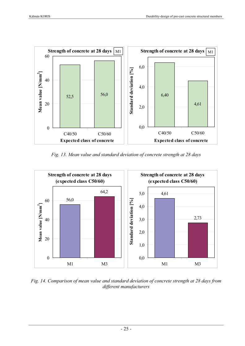
3. DETERMINATION OF PROCESS PARAMETERS Result of any probabilistic structural analysis can be accurate enough only if the appropriate values of input parameters are used [45]. Many efforts have been made on the determination of the process parameters (e.g. [3], [47]) before, but the applicability of such results is quite limited. In case of pre-cast concrete members, the quality of used materials as well as the properties of the final product are usually measured and documented. The use of the documents regarding to the quality control can assure an appropriate basis for the durability-design of these concrete members by stochastic approach. The list of input parameters that can be obtained from these test record sheets (see Appendix A1) includes the strength and elastic modulus of applied materials (concrete, steel bars, prestressing tendons) as well as the geometry of the final product (length, height, width, concrete cover). For the analysis described in Chapter 2., input parameters were obtained from destructive material tests and measurements on pre-cast members performed by industrial prefabricating companies. Products of 7 different Hungarian companies were considered. Company names are not mentioned upon request so they will be just referred as M1, M2, M3, etc. For the appropriate durability analysis, changes of the initial input values over a given time period must also be known. Consideration of the effect of time on the input parameters is described in Chapter 3.2. 3.1. Initial value of material properties Concrete strength was obtained from uniaxial compression tests carried out on 150×150×150 mm cubes (see Fig. 10.) [59], [61] and [63]. 78 specimens of 4 different expected concrete classes were tested at the age of 7 days and 732 specimens of 2 different classes were tested at 28 days in the laboratories of 3 different prefabricating companies. Cube strength was measured during the test which was transformed to cylinder strength for the calculations. Mean value and standard deviation of concrete strength was calculated for the different expected classes. The strength values at the age of 7 days were used for the control of prestressed beams after the transfer of the prestressing force. Concrete strengths measured at the age of 28 days were used as initial values for the calculations. Results on the concrete strength at 7 days are represented in Fig. 11. and Fig. 12., results at 28 days are illustrated in Fig. 13. and Fig. 14. Comparing the results at 7 and 28 days (Fig. 14.) it can be stated that mean value of concrete strength is increasing while its standard deviation is decreasing according to the expected strength development of concrete. Mean value and standard deviation of strength was compared in case of concrete prepared by different manufacturers. The expected class was C50/60 for both set of specimens, however, the difference between the mean values of strength was about 15% and the difference between standard deviations was almost 69%. A difference of this scale can result in considerable change of the variance of structural resistance (see Chapter 4.1.) and the probability of failure. In this manner the use of corresponding input parameters is essential for the accuracy of the results. The number of tested concrete specimens in case of different concrete classes and different manufacturing companies are listed in Tab. 2.
Fig. 10. Concrete cube specimenafter compression test

Kálmán KORIS Durability-design of pre-cast concrete structural members
- 23 -
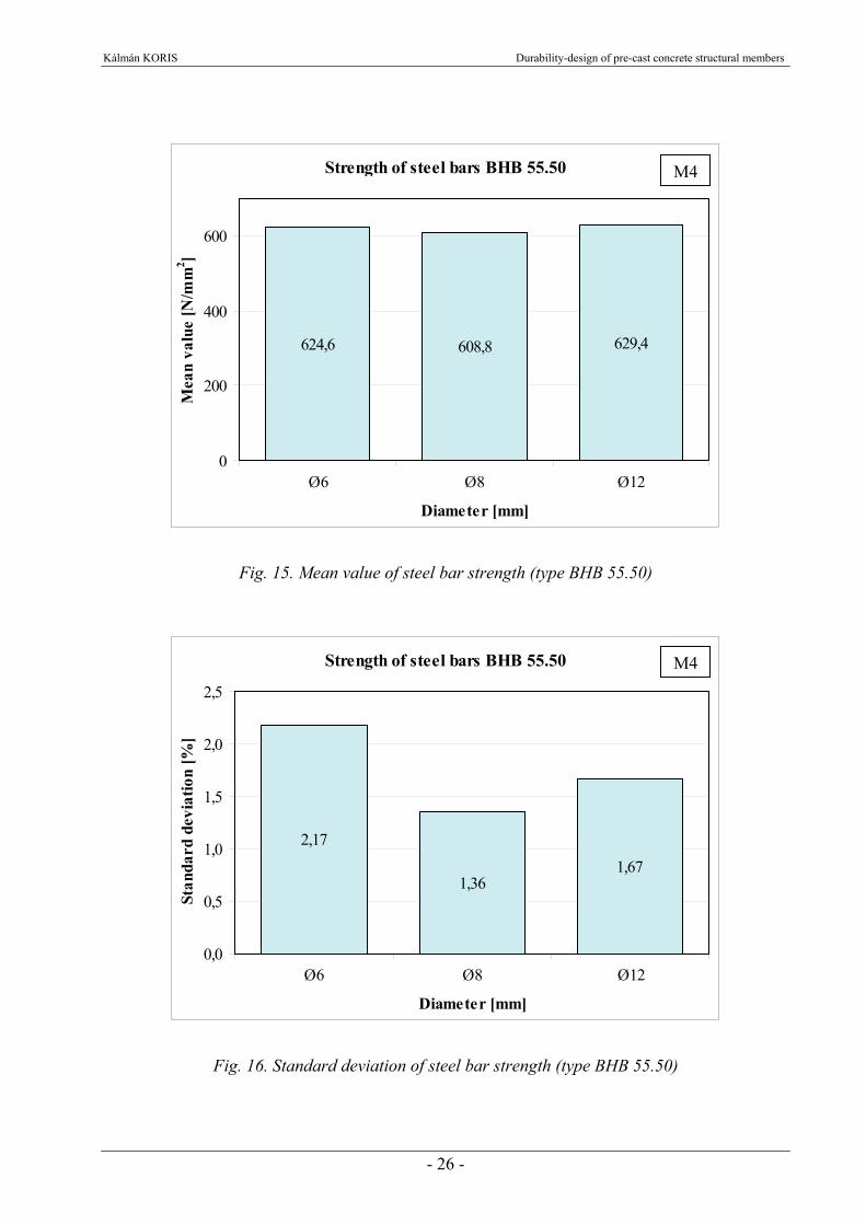
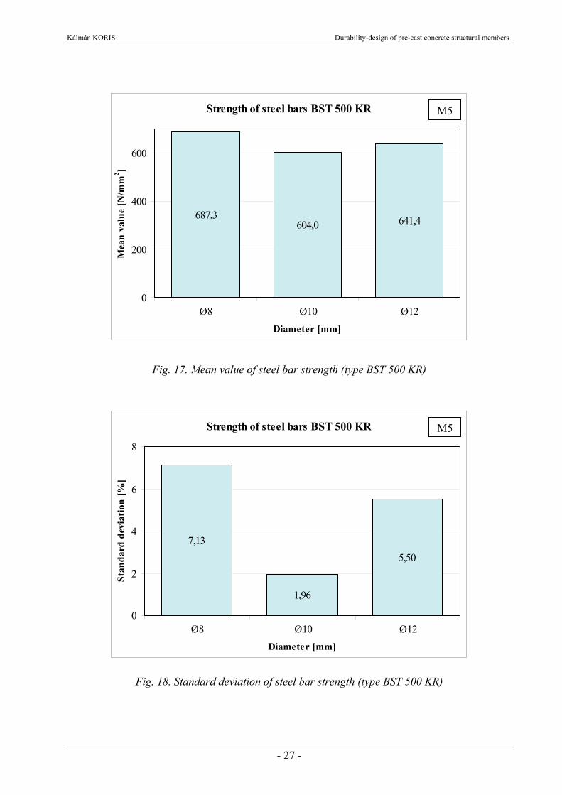
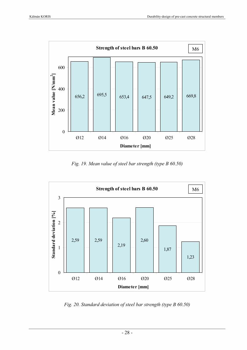
Laboratory tensile tests were carried out to determine material properties of reinforcing steel [64], [65] and [66]. Steel bars from 3 different manufacturers were analyzed on altogether 291 specimens. The numbers of tested steel bar specimens in case of different steel grades and different manufacturing companies are listed in Tab. 2. (see also Appendix A1). The modulus of elasticity, strength and the ultimate strain of the samples were measured. Mean value and standard deviation of these quantities were evaluated. Results on mean values and standard deviations of steel strength are presented graphically in case bars with different diameter (Fig. 15., Fig. 16., Fig. 17., Fig. 18., Fig. 19., Fig. 20.). In case of Young’s modulus and ultimate strain, only the mean values were used for the calculation.
ManufacturerNumber of
tested/measured specimens
C40/50, 28 days M1 54C50/60, 28 days M1 42C30/37, 7 days M2 9C35/45, 7 days M2 12C40/50, 7 days M2 54C60/75, 7 days M2 3C50/60, 28 days M3 636BHB55.50, Ø6 M4 3BHB55.50, Ø8 M4 4BHB55.50, Ø12 M4 5BST 500 KR, Ø8 M5 52BST 500 KR, Ø10 M5 28BST 500 KR, Ø12 M5 5B60.50, Ø12 M6 20B60.50, Ø14 M6 15B60.50, Ø16 M6 20B60.50, Ø20 M6 89B60.50, Ø25 M6 45B60.50, Ø28 M6 5Fp 38/1770-R2 M7 3Fp 100/1770-R2 M7 20EE-42 M2 7EE-48 M2 11EE-54 M2 5EE-66 M2 44000 M1 114700 M1 10
Prestressed beam
Type of material or beam
Concrete
Steel bar
Prestressing tendon
Tab. 2. List of tested materials and prestressed beams

Kálmán KORIS Durability-design of pre-cast concrete structural members
- 24 -
Strength of concrete at 7 days
37,8
49,044,4
49,9
0
10
20
30
40
50
C30/37 C35/45 C40/50 C60/75
Expected class of concrete
Mea
n va
lue
[N/m
m2 ]
Fig. 11. Mean value of concrete strength at 7 days
Strength of concrete at 7 days
6,04,9
11,0
1,40
2
4
6
8
10
12
C30/37 C35/45 C40/50 C60/75
Expected class of concrete
Stan
dard
dev
iatio
n [%
]
Fig. 12. Standard deviation of concrete strength at 7 days
M2
M2
Kálmán KORIS Durability-design of pre-cast concrete structural members
- 25 -
Strength of concrete at 28 days
52,5 56,0
0
20
40
60
C40/50 C50/60Expected class of concrete
Mea
n va
lue
[N/m
m2 ]
Strength of concrete at 28 days
6,40
4,61
0,0
2,0
4,0
6,0
C40/50 C50/60Expected class of concrete
Stan
dard
dev
iatio
n [%
]
Fig. 13. Mean value and standard deviation of concrete strength at 28 days
Strength of concrete at 28 days (expected class C50/60)
56,0
64,2
0
20
40
60
M1 M3
Mea
n va
lue
[N/m
m2 ]
Strength of concrete at 28 days(expected class C50/60)
4,61
2,73
0,0
1,0
2,0
3,0
4,0
5,0
M1 M3
Stan
dard
dev
iatio
n [%
]
Fig. 14. Comparison of mean value and standard deviation of concrete strength at 28 days from different manufacturers
M1M1
Kálmán KORIS Durability-design of pre-cast concrete structural members
- 26 -
Strength of steel bars BHB 55.50
624,6 608,8 629,4
0
200
400
600
Ø6 Ø8 Ø12
Diameter [mm]
Mea
n va
lue
[N/m
m2 ]
Fig. 15. Mean value of steel bar strength (type BHB 55.50)
Strength of steel bars BHB 55.50
2,17
1,361,67
0,0
0,5
1,0
1,5
2,0
2,5
Ø6 Ø8 Ø12
Diameter [mm]
Stan
dard
dev
iatio
n [%
]
Fig. 16. Standard deviation of steel bar strength (type BHB 55.50)
M4
M4
Kálmán KORIS Durability-design of pre-cast concrete structural members
- 27 -
Strength of steel bars BST 500 KR
687,3604,0 641,4
0
200
400
600
Ø8 Ø10 Ø12Diameter [mm]
Mea
n va
lue
[N/m
m2 ]
Fig. 17. Mean value of steel bar strength (type BST 500 KR)
Strength of steel bars BST 500 KR
7,13
1,96
5,50
0
2
4
6
8
Ø8 Ø10 Ø12Diameter [mm]
Stan
dard
dev
iatio
n [%
]
Fig. 18. Standard deviation of steel bar strength (type BST 500 KR)
M5
M5
Kálmán KORIS Durability-design of pre-cast concrete structural members
- 28 -
Strength of steel bars B 60.50
656,2 695,5 653,4 647,5 649,2 669,8
0
200
400
600
Ø12 Ø14 Ø16 Ø20 Ø25 Ø28
Diameter [mm]
Mea
n va
lue
[N/m
m2 ]
Fig. 19. Mean value of steel bar strength (type B 60.50)
Strength of steel bars B 60.50
2,59 2,592,19
2,60
1,87
1,23
0
1
2
3
Ø12 Ø14 Ø16 Ø20 Ø25 Ø28
Diameter [mm]
Stan
dard
dev
iatio
n [%
]
Fig. 20. Standard deviation of steel bar strength (type B 60.50)
M6
M6
Kálmán KORIS Durability-design of pre-cast concrete structural members
- 29 -
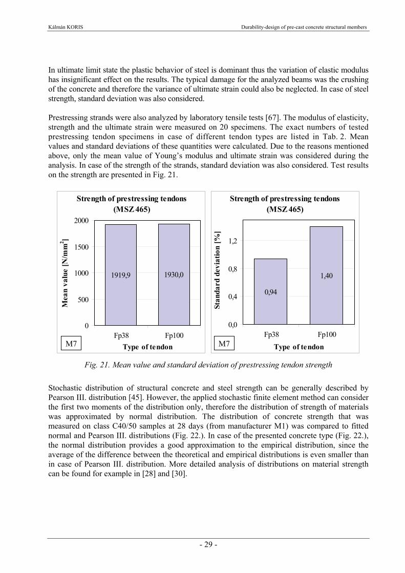
In ultimate limit state the plastic behavior of steel is dominant thus the variation of elastic modulus has insignificant effect on the results. The typical damage for the analyzed beams was the crushing of the concrete and therefore the variance of ultimate strain could also be neglected. In case of steel strength, standard deviation was also considered. Prestressing strands were also analyzed by laboratory tensile tests [67]. The modulus of elasticity, strength and the ultimate strain were measured on 20 specimens. The exact numbers of tested prestressing tendon specimens in case of different tendon types are listed in Tab. 2. Mean values and standard deviations of these quantities were calculated. Due to the reasons mentioned above, only the mean value of Young’s modulus and ultimate strain was considered during the analysis. In case of the strength of the strands, standard deviation was also considered. Test results on the strength are presented in Fig. 21.
Strength of prestressing tendons (MSZ 465)
1919,9 1930,0
0
500
1000
1500
2000
Fp38 Fp100Type of tendon
Mea
n va
lue
[N/m
m2 ]
Strength of prestressing tendons (MSZ 465)
0,94
1,40
0,0
0,4
0,8
1,2
Fp38 Fp100Type of tendon
Stan
dard
dev
iatio
n [%
]
Fig. 21. Mean value and standard deviation of prestressing tendon strength
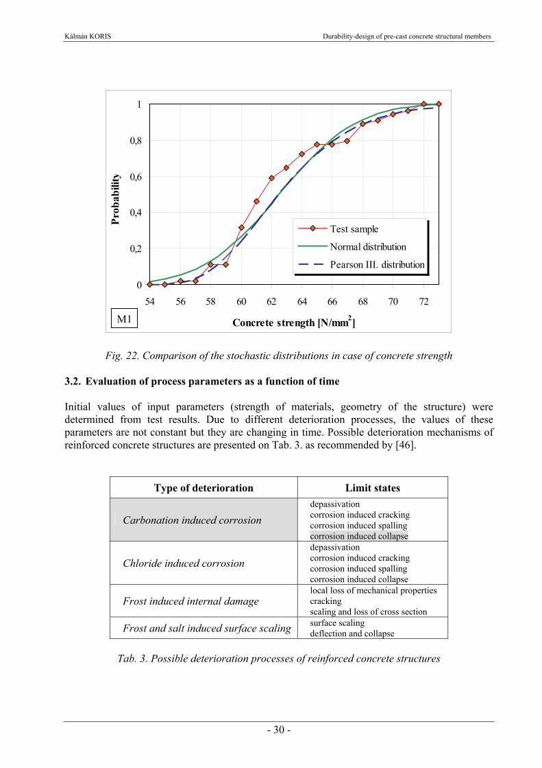
Stochastic distribution of structural concrete and steel strength can be generally described by Pearson III. distribution [45]. However, the applied stochastic finite element method can consider the first two moments of the distribution only, therefore the distribution of strength of materials was approximated by normal distribution. The distribution of concrete strength that was measured on class C40/50 samples at 28 days (from manufacturer M1) was compared to fitted normal and Pearson III. distributions (Fig. 22.). In case of the presented concrete type (Fig. 22.), the normal distribution provides a good approximation to the empirical distribution, since the average of the difference between the theoretical and empirical distributions is even smaller than in case of Pearson III. distribution. More detailed analysis of distributions on material strength can be found for example in [28] and [30].
M7M7
Kálmán KORIS Durability-design of pre-cast concrete structural members
- 30 -
0
0,2
0,4
0,6
0,8
1
54 56 58 60 62 64 66 68 70 72
Concrete strength [N/mm2]
Prob
abili
ty
Test sample
Normal distribution
Pearson III. distribution
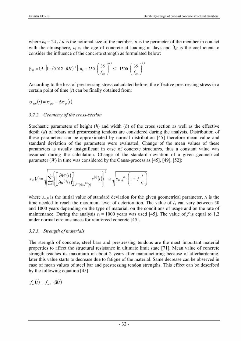
Fig. 22. Comparison of the stochastic distributions in case of concrete strength 3.2. Evaluation of process parameters as a function of time Initial values of input parameters (strength of materials, geometry of the structure) were determined from test results. Due to different deterioration processes, the values of these parameters are not constant but they are changing in time. Possible deterioration mechanisms of reinforced concrete structures are presented on Tab. 3. as recommended by [46].
Type of deterioration Limit states
Carbonation induced corrosion depassivation corrosion induced cracking corrosion induced spalling corrosion induced collapse
Chloride induced corrosion depassivation corrosion induced cracking corrosion induced spalling corrosion induced collapse
Frost induced internal damage local loss of mechanical properties cracking scaling and loss of cross section
Frost and salt induced surface scaling surface scaling deflection and collapse
Tab. 3. Possible deterioration processes of reinforced concrete structures
M1

Kálmán KORIS Durability-design of pre-cast concrete structural members
- 31 -
In frames of the dissertation, the collapse of the structure due to carbonation induced corrosion was analyzed. The process of carbonation is getting slower as the concrete strength is increasing. For concrete classes higher than C40/50 (which is common for pre-cast concrete members) the carbonation induced corrosion first evolves after 40-50 years only. However pre-cast concrete members are also used for structures with a life-span of 50-150 years (e.g. bridges) so it is important to consider the effect of carbonation as well. Determination method of time-dependent parameters is described below. 3.2.1. Effective prestressing stress The initial value of prestressing stress (σp0) is usually determined so that plastic deformations of prestressing tendons are avoided [29]. The usual value for this stress is about 1200-1300 N/mm2 depending on the established custom of the manufacturer. During the calculations, the value σp0 = 1300 N/mm2 was used. The loss of prestressing stress was determined according to [21] in a give point of time (t):
( ) ( )
( )[ ]t,zIA
AA
t,Et
cpc
c
c
pp
QP,cpprpcsp
ϕ+⋅⎟⎟⎠
⎞⎜⎜⎝
⎛+α+
σ⋅ϕ⋅α+σΔ+⋅ε=σΔ
80111
80
2
where εcs is the shrinkage strain, Δσpr is the value of relaxation loss, ϕ(t) is the creep coefficient, Ep is the modulus of elasticity for the prestressing steel, σc,QP is the stress in the concrete adjacent to the tendons due to self-weight and initial prestress, zcp is the distance between the centre of gravity of the concrete section and the tendons. Using normal or rapid hardening cements, the shrinkage strain can be obtained from the following equation [21]:
⎪⎭
⎪⎬⎫
⎪⎩
⎪⎨⎧
⎥⎥⎦
⎤
⎢⎢⎣
⎡⎟⎠⎞
⎜⎝⎛−⋅−⋅⋅⋅=ε
⋅−−3
101206
100155110561 RH,e
cmf,
cs
where RH is the ambient relative humidity in [%] and fcm is the mean value of concrete strength. The relaxation loss can be calculated from [21]:
( )μ−μ⋅
⎟⎟⎠
⎞⎜⎜⎝
⎛⋅⋅ρ
σ=σΔ
1750
10000
10001000
,pBp
pr
teA
where the value of A is equal to 5,39 in case of prestressing wires and 0,66 in case of strands, the value of B is 6,7 in case of wires and 9,1 in case of strands, tp is the time elapsed since prestressing in hours, μ = σp0/fpm and ρ1000 is the relaxation loss after 1000 hours at a temperature of 20 ºC, fpm is the mean value of tendon strength, finally ρ1000 = 8% can be considered in case of wires and ρ1000 = 2,5% in case of strands. The creep coefficient can be obtained from [21]:
( )30
0
020
0
2070
30 10
1816353510
10011,
H,
cm
,
cm
,
cm tttt
t,f,
ffh,/RHt ⎥
⎦
⎤⎢⎣
⎡−+β
−⋅
+⋅⋅⎟⎟
⎠
⎞⎜⎜⎝
⎛⋅
⎥⎥⎦
⎤
⎢⎢⎣
⎡⎟⎟⎠
⎞⎜⎜⎝
⎛⋅
⋅−+=ϕ
Kálmán KORIS Durability-design of pre-cast concrete structural members
- 32 -
where h0 = 2Ac / u is the notional size of the member, u is the perimeter of the member in contact with the atmosphere, t0 is the age of concrete at loading in days and βH is the coefficient to consider the influence of the concrete strength as formulated below:
( )[ ]5050
018 351500352500120151
,
cm
,
cmH ff
hRH,, ⎟⎟⎠
⎞⎜⎜⎝
⎛⋅≤⎟⎟
⎠
⎞⎜⎜⎝
⎛⋅+⋅⋅+⋅=β
According to the loss of prestressing stress calculated before, the effective prestressing stress in a certain point of time (t) can be finally obtained from:
( ) ( )tt pppm σΔ−σ=σ 0 3.2.2. Geometry of the cross-section Stochastic parameters of height (h) and width (b) of the cross section as well as the effective depth (d) of rebars and prestressing tendons are considered during the analysis. Distribution of these parameters can be approximated by normal distribution [45] therefore mean value and standard deviation of the parameters were evaluated. Change of the mean values of these parameters is usually insignificant in case of concrete structures, thus a constant value was assumed during the calculation. Change of the standard deviation of a given geometrical parameter (W) in time was considered by the Gauss-process as [45], [49], [52]:
( ) ( )( ) ( ) ( ) ( ) ( ) ( )
( ) ( ) ⎟⎟⎠
⎞⎜⎜⎝
⎛+⋅≅
⎪⎭
⎪⎬⎫
⎪⎩
⎪⎨⎧
⎥⎦
⎤⎢⎣
⎡∂∂= ∑
= = 1
20
0
2
1ttfsts
tutWts ,W
n
i
i
tutuiW
ii
where sw,0 is the initial value of standard deviation for the given geometrical parameter, t1 is the time needed to reach the maximum level of deterioration. The value of t1 can vary between 50 and 1000 years depending on the type of material, on the conditions of usage and on the rate of maintenance. During the analysis t1 = 1000 years was used [45]. The value of f is equal to 1,2 under normal circumstances for reinforced concrete [45]. 3.2.3. Strength of materials The strength of concrete, steel bars and prestressing tendons are the most important material properties to affect the structural resistance in ultimate limit state [71]. Mean value of concrete strength reaches its maximum in about 2 years after manufacturing because of afterhardening, later this value starts to decrease due to fatigue of the material. Same decrease can be observed in case of mean values of steel bar and prestressing tendon strengths. This effect can be described by the following equation [45]:
( ) ( )tftf mm β⋅= 0
Kálmán KORIS Durability-design of pre-cast concrete structural members
- 33 -
where f(t) is the mean value of strength at the time t, f0 is the initial mean value of strength and β(t) is the function describing the decrease of the strength. Assuming a time period t0 in which the strength of the material decreases to zero, β(t) can be expressed by the first few terms of its Taylor-series [45]:
( )4
0
3
0
2
0 31
31
311 ⎟⎟
⎠
⎞⎜⎜⎝
⎛−⎟⎟
⎠
⎞⎜⎜⎝
⎛−⎟⎟
⎠
⎞⎜⎜⎝
⎛−≅β
tt
tt
ttt {15}
The value of t0 can usually vary between 50 and 1000 years depending on the type of material, on the conditions of usage and on the rate of maintenance. During the analysis, t0 = 500 years was assumed. Standard deviation of material strength also changes during time. This effect can be again described by the Gauss-process [45]:
( )⎥⎥⎦
⎤
⎢⎢⎣
⎡⎟⎟⎠
⎞⎜⎜⎝
⎛+⋅=
k
ff ttbsts0
20 1 {16}
where sf(t) is the standard deviation of strength at the time t, sf0 is the initial value of standard deviation, b and k are constants describing the increase of standard deviation. The exact values of constants b and k can be usually determined empirically (see Chapter 4.2.5.). In case of concrete, the values b = 1,5 and k = 1 were used, for steel bars and tendons the values b = 1,4 and k = 1,2 were applied during the analysis based on the recommendations of [45]. 3.2.4. Carbonation induced corrosion of steel bars and tendons Decrease of steel bar and tendon diameter due to carbonation induced corrosion was also considered in the calculation. The carbonation depth at the time t can be expressed from the following equation [46]:
( ) ( ) ( )tWtCRkkktx st,ACCtcec ⋅⋅⋅ε+⋅⋅⋅⋅= −102 {17}
where ke is the environmental function, kc is the execution transfer parameter, kt = 1,25 is the regression parameter, 1
0,−ACCR is the inverse effective carbonation resistance of concrete derived
from accelerated test (ACC), εt = 315,5 (mm2/years)/(kg/m3) is the error term considering inaccuracies which occur conditionally when using ACC test method, Cs is the CO2 concentration and W(t) is the weather function that takes the effect of rain events on the concrete carbonation into account. The environmental function can be expressed as:
52
5
5
100651
1001
,
real
e
RH
k
⎟⎟⎟⎟⎟
⎠
⎞
⎜⎜⎜⎜⎜
⎝
⎛
⎟⎠⎞
⎜⎝⎛−
⎟⎠⎞
⎜⎝⎛−
=
Kálmán KORIS Durability-design of pre-cast concrete structural members
- 34 -
where RHreal [%] is the relative humidity of the carbonated layer. The relative humidity of the carbonated layer was assumed to be same as the relative ambient humidity (RH). The relative ambient humidity is one of the most important factors to influence the process of carbonation and its value can be measured or controlled during the service life of the structure, therefore it was used as a variable parameter in the further calculations. The execution transfer parameter can be calculated from the following expression:
5670
7
,c
ct
k−
⎟⎠⎞
⎜⎝⎛=
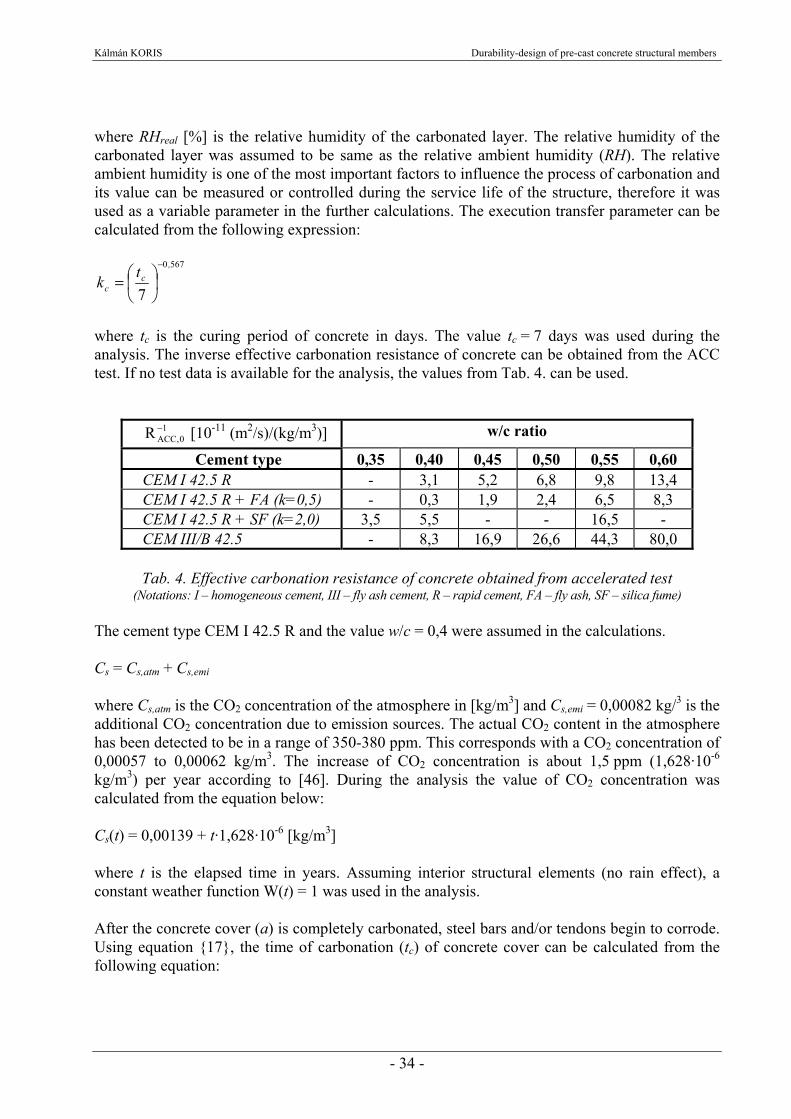
where tc is the curing period of concrete in days. The value tc = 7 days was used during the analysis. The inverse effective carbonation resistance of concrete can be obtained from the ACC test. If no test data is available for the analysis, the values from Tab. 4. can be used.
10,ACCR − [10-11 (m2/s)/(kg/m3)] w/c ratio
Cement type 0,35 0,40 0,45 0,50 0,55 0,60 CEM I 42.5 R - 3,1 5,2 6,8 9,8 13,4 CEM I 42.5 R + FA (k=0,5) - 0,3 1,9 2,4 6,5 8,3 CEM I 42.5 R + SF (k=2,0) 3,5 5,5 - - 16,5 - CEM III/B 42.5 - 8,3 16,9 26,6 44,3 80,0
Tab. 4. Effective carbonation resistance of concrete obtained from accelerated test
(Notations: I – homogeneous cement, III – fly ash cement, R – rapid cement, FA – fly ash, SF – silica fume) The cement type CEM I 42.5 R and the value w/c = 0,4 were assumed in the calculations. Cs = Cs,atm + Cs,emi where Cs,atm is the CO2 concentration of the atmosphere in [kg/m3] and Cs,emi = 0,00082 kg/3 is the additional CO2 concentration due to emission sources. The actual CO2 content in the atmosphere has been detected to be in a range of 350-380 ppm. This corresponds with a CO2 concentration of 0,00057 to 0,00062 kg/m3. The increase of CO2 concentration is about 1,5 ppm (1,628·10-6 kg/m3) per year according to [46]. During the analysis the value of CO2 concentration was calculated from the equation below: Cs(t) = 0,00139 + t·1,628·10-6 [kg/m3] where t is the elapsed time in years. Assuming interior structural elements (no rain effect), a constant weather function W(t) = 1 was used in the analysis. After the concrete cover (a) is completely carbonated, steel bars and/or tendons begin to corrode. Using equation {17}, the time of carbonation (tc) of concrete cover can be calculated from the following equation:
Kálmán KORIS Durability-design of pre-cast concrete structural members
- 35 -
a = xc(tc) The process of corrosion is an electrochemical reaction. The relation between the diameter of rusted steel bar and corrosion time under normal atmospheric conditions is outlined as [72]:
( ) ( )∫−∅=∅t
corr dtti,t0
0 02320
where t is the time of corrosion measured from the time point tc, Ø0 [mm] is the diameter of steel bar before corrosion and icorr(t) represents current corrosion density at time t.
( ) ( ) 290641
8501837 ,,
corr t,acw,ti −
−
⋅⋅−=
where w/c is the water/cement ratio of the concrete. The area of steel bars or tendons in a certain point of time can be obtained from:
( ) ( )4
2 π⋅∅= ttA p,s
where t is the elapsed time since the time point tc as described above. Steel bars are usually closer to the surface of the concrete than the prestressing tendons, therefore they start to corrode earlier (see Fig. 42. and Fig. 54.). 3.2.5. Load effect The effect of self-weight and imposed load was considered during the analysis. The mean value of self-weight was described as a function of structural geometry and the volume density of reinforced concrete:
( ) ( )[ ]rc,th,tbf)t(g ρ= where b(t) and h(t) are the width and height of the cross-section as a function of time, ρrc = 25 kN/m3 is the volume density of reinforced concrete. The standard deviation of self-weight was calculated from the standard deviations of its input parameters [45]:
( ) ( ) ( )[ ] ( ) ( )[ ] ( ) ( )[ ] 222
⎟⎟⎠
⎞⎜⎜⎝
⎛ρ∂
ρ∂+⎟⎟
⎠
⎞⎜⎜⎝
⎛∂
ρ∂+⎟⎟
⎠
⎞⎜⎜⎝
⎛∂
ρ∂= ρs
,th,tbfs
h,th,tbf
sb
,th,tbfts
rc
rch
rcd
rcg
where sb, sh and sρ are the standard deviation of cross-sectional width and height and the volume density of concrete respectively. The relative standard deviation of volume density can be assumed to 4% in case of concrete.
Kálmán KORIS Durability-design of pre-cast concrete structural members
- 36 -
In case of imposed loads, the distribution is not independent from the length of examination period. It means that these loads are stochastic functions of time. The load part equivalent to 10% of the time-span probability was supposed to be permanent load [45]. The yearly maximums of imposed load were described by type I. extreme value distribution and the change of its mean value in time can be written as [45], [49], [52]:
( )λ
+λ
+⋅= tln,qtqm577216010
where q0 is the initial mean value of imposed load, t is the time in years and λ is the parameter of the distribution. In case of the applied imposed load, the λ parameter can be obtained from:
3579306 ,⋅π=λ
The standard deviation of the applied imposed load can be calculated as a function of the initial value of standard deviation (sq0):
2
2
0 6λπ= qq ss
The mean value of design load as a function of time was obtained from the sum of the self-weight and the imposed load: pm(t) = gm(t) + qm(t) The value of standard deviation of the design load was approximately calculated as a function of time by the Gaussian law of error distribution:
( ) ( ) 22qgp ststs +=

Kálmán KORIS Durability-design of pre-cast concrete structural members
- 37 -
4. APPLICATION OF THE IMPLEMENTED DESIGN METHOD 4.1. Verification of the method by bending tests
4.1.1. Analyzed beams and test results
Bending tests on prestressed concrete beams were carried out to determine the ultimate load [62]. 4 different kinds of beam type “EE” were tested in the laboratory at age of 28 days. “EE” beams (see Fig. 23.) are often used for the construction of roofs in houses [50]. These types of beams are popular due to their relatively light weight, easy assemblage and reasonable price. The total number of tested beams was 26. The test arrangement and the cross-section of the beam are presented in Fig. 24. Length of beam, height of the cross-section, width of the top and bottom flange and the concrete cover of the prestressing wires were measured before the test. Beams were loaded until failure in steps by four forces of equal value. The loading force
and the corresponding deflection of the midspan were recorded for each load step. The ultimate load was also documented for each beam. The mean values of measured geometrical sizes and ultimate loads in case of different beams are presented in Tab. 5. Standard deviation of structural geometry and ultimate load for different beams are presented in Tab. 6. Parameters concerning geometrical sizes were considered during the SFEM analysis. Results on the ultimate load obtained from the analysis were compared to test results to verify the implemented method.
Fig. 24. Bending test arrangement of beam type EE-42
Cross-section (EE-42)
bf
ba
h a
h f a p
b
h d p
Concrete: C40/50 Prestressing wires: d = 5mm 1770/1540
L
L/5 L/5L/5L/5 L/5
F/4 F/4 F/4 F/4
Test arrangement
Lb
Fig. 23. Beams of type “EE” after manufacture

Kálmán KORIS Durability-design of pre-cast concrete structural members
- 38 -
Type of beam L[m]
Number of wires
Lbm
[m]hm
[mm]bf,m
[mm]ba,m
[mm]ap,m
[mm]dp,m
[mm]Fu,m
[kN]EE-42 4,27 1+4 4,40 189,8 80,8 144,1 37,8 168,5 49,28EE-48 4,87 1+6 5,01 195,2 80,6 145,4 30,8 175,4 53,93EE-54 5,47 1+6 5,64 196,1 81,7 144,4 39,5 176,5 51,60EE-66 6,67 1+6 6,85 197,1 79,8 142,3 45,7 175,3 47,50
Tab. 5. Mean values of geometrical sizes and ultimate load (Fu) of different “EE” beams
Type of beam L[m]
Number of wires
νLb
[%]νh
[%]νbf
[%]νba
[%]νap
[%]νdp
[%]νFu
[%]EE-42 4,27 1+4 0,171 1,60 3,13 1,59 18,21 1,73 6,92EE-48 4,87 1+6 0,224 1,86 1,30 1,49 19,48 0,86 3,86EE-54 5,47 1+6 0,119 2,72 1,96 1,98 11,32 2,07 6,32EE-66 6,67 1+6 0,084 2,27 0,48 0,23 4,42 0,92 6,93
Tab. 6. Standard deviations of geometrical sizes and ultimate load (Fu) of different “EE” beams
4.1.2. Results of SFEM analysis The mean value and standard deviation of the presented “EE” beams were calculated by the method described in Chapter 2. Mean values and standard deviations of structural sizes were obtained from the test results (Tab. 5. and Tab. 6.). In case of beam length, the mean value was considered only, since its standard deviation was insignificant (~0,1-0,2%). Mean value and standard deviation of concrete and prestressing wire strengths were obtained from material test results described in Chapter 3.1. The concrete class of the beams was C40/50 thus the values fc,m = 52,5 N/mm2 and νfc = 6,4 % were used (see Fig. 13.). In case of wires, the values fp,m = 1919,9 N/mm2 and νfp = 0,94 % were applied (see Fig. 21.). The bending moment-curvature diagrams calculated for different beam types are presented in Fig. 25. As it was described in Chapter 2.4.2., the stiffness of the beam depends on the values of internal forces. The decrease of bending stiffness (Ec·Ix in case of elastic deformations or Mx/κx in case of plastic deformations) during SFEM analysis in case of beam type “EE-42” is presented in Fig. 26. It can be stated that plastic behavior of prestressed concrete is dominant along the beam in ultimate limit state. According to Chapter 2.4.2. the method of load increments was used during the analyses. For each load step the appropriate deflection of the midspan and the variation of load-intensity were calculated. The load-deflection curves including the standard deviation of the load-intensity in case of beam types “EE-42” and “EE-48” are presented in Fig. 27. and Fig. 28. Mean value of structural resistance (Fu,m) calculated by SFEM are compared to test results in case of different beams in Fig. 29. It can be stated that there is a coherent difference (15-30 %) between the calculated and measured values. This difference is caused by the calculation method used to determine the failure of the cross-sections. The failure is usually related to the crushing of the concrete when the strain εcu = 3,5 ‰ is reached, or splitting of the reinforcement when the ultimate strain (εsu, εpu) is exceeded in the bars.
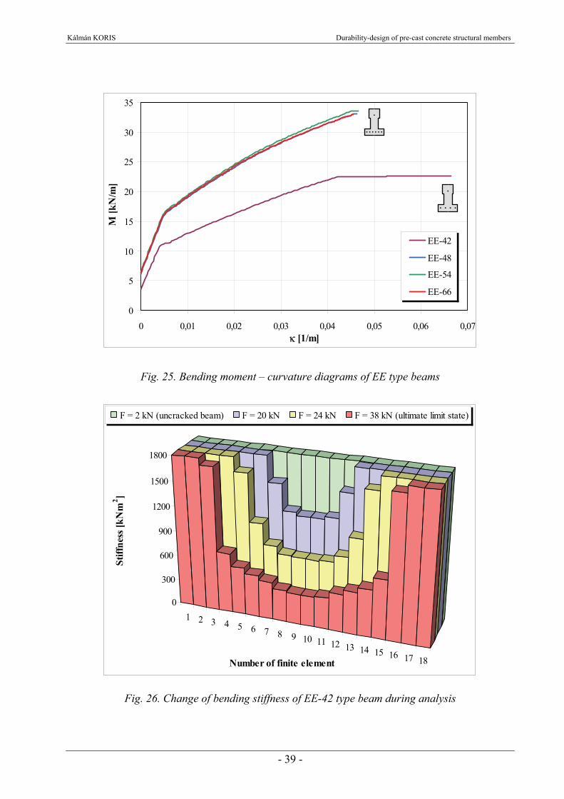
Kálmán KORIS Durability-design of pre-cast concrete structural members
- 39 -
0
5
10
15
20
25
30
35
0 0,01 0,02 0,03 0,04 0,05 0,06 0,07κ [1/m]
M [k
N/m
]
EE-42
EE-48
EE-54
EE-66
Fig. 25. Bending moment – curvature diagrams of EE type beams
1 2 3 4 5 6 7 8 9 10 11 12 13 14 15 16 17 18
0
300
600
900
1200
1500
1800
Stiff
ness
[kN
m2 ]
Number of finite element
F = 2 kN (uncracked beam) F = 20 kN F = 24 kN F = 38 kN (ultimate limit state)
Fig. 26. Change of bending stiffness of EE-42 type beam during analysis

Kálmán KORIS Durability-design of pre-cast concrete structural members
- 40 -
Load-deflection curve for beam type EE-42
0
5
10
15
20
25
30
35
40
45
-0,02 0,00 0,02 0,04 0,06 0,08 0,10
u [m]
F [k
N]
Mean value
Mean value + standard deviation
Mean value – standard deviation
Fig. 27. Load-deflection diagram of EE-42 type beam calculated by SFEM
Load-deflection curve for beam type EE-48
0
10
20
30
40
50
-0,02 0,00 0,02 0,04 0,06 0,08 0,10
u [m]
F [k
N]
Mean value
Mean value + standard deviation
Mean value – standard deviation
Fig. 28. Load-deflection diagram of EE-48 type beam calculated by SFEM
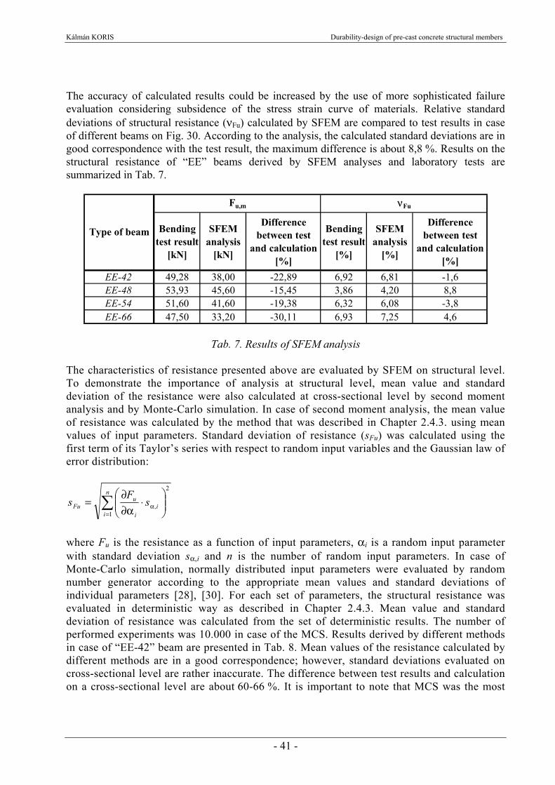
Kálmán KORIS Durability-design of pre-cast concrete structural members
- 41 -
The accuracy of calculated results could be increased by the use of more sophisticated failure evaluation considering subsidence of the stress strain curve of materials. Relative standard deviations of structural resistance (νFu) calculated by SFEM are compared to test results in case of different beams on Fig. 30. According to the analysis, the calculated standard deviations are in good correspondence with the test result, the maximum difference is about 8,8 %. Results on the structural resistance of “EE” beams derived by SFEM analyses and laboratory tests are summarized in Tab. 7.
Bending test result
[kN]
SFEM analysis
[kN]
Difference between test
and calculation [%]
Bending test result
[%]
SFEM analysis
[%]
Difference between test
and calculation [%]
EE-42 49,28 38,00 -22,89 6,92 6,81 -1,6EE-48 53,93 45,60 -15,45 3,86 4,20 8,8EE-54 51,60 41,60 -19,38 6,32 6,08 -3,8EE-66 47,50 33,20 -30,11 6,93 7,25 4,6
Fu,m νFu
Type of beam
Tab. 7. Results of SFEM analysis
The characteristics of resistance presented above are evaluated by SFEM on structural level. To demonstrate the importance of analysis at structural level, mean value and standard deviation of the resistance were also calculated at cross-sectional level by second moment analysis and by Monte-Carlo simulation. In case of second moment analysis, the mean value of resistance was calculated by the method that was described in Chapter 2.4.3. using mean values of input parameters. Standard deviation of resistance (sFu) was calculated using the first term of its Taylor’s series with respect to random input variables and the Gaussian law of error distribution:
∑=
α ⎟⎟⎠
⎞⎜⎜⎝
⎛⋅
α∂∂
=n
ii,
i
uFu s
Fs
1
2
where Fu is the resistance as a function of input parameters, αi is a random input parameter with standard deviation sα,i and n is the number of random input parameters. In case of Monte-Carlo simulation, normally distributed input parameters were evaluated by random number generator according to the appropriate mean values and standard deviations of individual parameters [28], [30]. For each set of parameters, the structural resistance was evaluated in deterministic way as described in Chapter 2.4.3. Mean value and standard deviation of resistance was calculated from the set of deterministic results. The number of performed experiments was 10.000 in case of the MCS. Results derived by different methods in case of “EE-42” beam are presented in Tab. 8. Mean values of the resistance calculated by different methods are in a good correspondence; however, standard deviations evaluated on cross-sectional level are rather inaccurate. The difference between test results and calculation on a cross-sectional level are about 60-66 %. It is important to note that MCS was the most
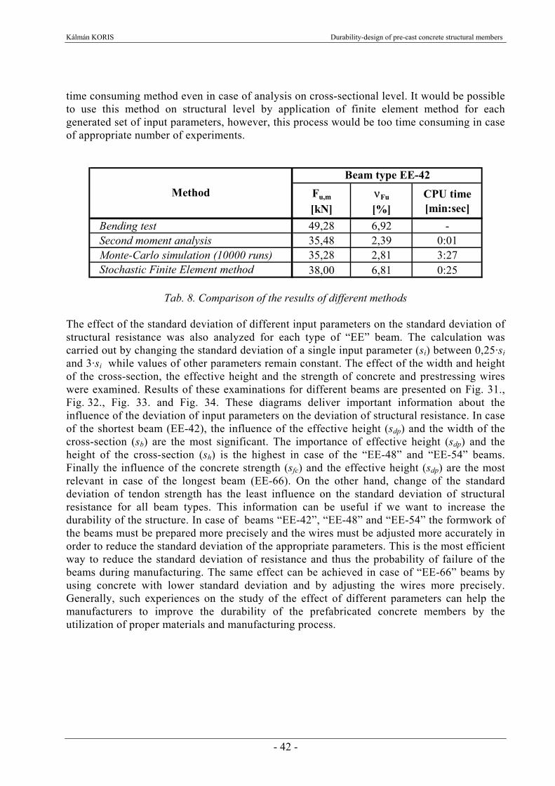
Kálmán KORIS Durability-design of pre-cast concrete structural members
- 42 -
time consuming method even in case of analysis on cross-sectional level. It would be possible to use this method on structural level by application of finite element method for each generated set of input parameters, however, this process would be too time consuming in case of appropriate number of experiments.
Fu,m
[kN]νFu
[%]CPU time [min:sec]
Bending test 49,28 6,92 -Second moment analysis 35,48 2,39 0:01Monte-Carlo simulation (10000 runs) 35,28 2,81 3:27Stochastic Finite Element method 38,00 6,81 0:25
MethodBeam type EE-42
Tab. 8. Comparison of the results of different methods The effect of the standard deviation of different input parameters on the standard deviation of structural resistance was also analyzed for each type of “EE” beam. The calculation was carried out by changing the standard deviation of a single input parameter (si) between 0,25·si and 3·si while values of other parameters remain constant. The effect of the width and height of the cross-section, the effective height and the strength of concrete and prestressing wires were examined. Results of these examinations for different beams are presented on Fig. 31., Fig. 32., Fig. 33. and Fig. 34. These diagrams deliver important information about the influence of the deviation of input parameters on the deviation of structural resistance. In case of the shortest beam (EE-42), the influence of the effective height (sdp) and the width of the cross-section (sb) are the most significant. The importance of effective height (sdp) and the height of the cross-section (sh) is the highest in case of the “EE-48” and “EE-54” beams. Finally the influence of the concrete strength (sfc) and the effective height (sdp) are the most relevant in case of the longest beam (EE-66). On the other hand, change of the standard deviation of tendon strength has the least influence on the standard deviation of structural resistance for all beam types. This information can be useful if we want to increase the durability of the structure. In case of beams “EE-42”, “EE-48” and “EE-54” the formwork of the beams must be prepared more precisely and the wires must be adjusted more accurately in order to reduce the standard deviation of the appropriate parameters. This is the most efficient way to reduce the standard deviation of resistance and thus the probability of failure of the beams during manufacturing. The same effect can be achieved in case of “EE-66” beams by using concrete with lower standard deviation and by adjusting the wires more precisely. Generally, such experiences on the study of the effect of different parameters can help the manufacturers to improve the durability of the prefabricated concrete members by the utilization of proper materials and manufacturing process.

Kálmán KORIS Durability-design of pre-cast concrete structural members
- 43 -
49,28
53,9351,60
47,50
38,0
45,6
41,6
33,2
10
20
30
40
50
60
EE-42 EE-48 EE-54 EE-66
Type of beam
Fu,m
[kN
]
Bending test result
SFEM analysis
Fig. 29. Measured and calculated mean values of ultimate load
7,25
6,93
3,86
6,92
6,32
6,08
4,20
6,81
3,5
4,0
4,5
5,0
5,5
6,0
6,5
7,0
7,5
EE-42 EE-48 EE-54 EE-66
Type of beam
νFu [
%]
Bending test result
SFEM analysis
Fig. 30. Measured and calculated standard deviations of ultimate load

Kálmán KORIS Durability-design of pre-cast concrete structural members
- 44 -
Beam type EE-42
6,0
6,5
7,0
7,5
8,0
8,5
9,0
9,5
10,0
10,5
11,0
0,25·s 0,5·s 0,75·s s 1,5·s 2·s 3·s
νFu [
%]
width of cross section
height of cross section
effective depth of wires
strength of concrete
strength of wires
Fig. 31. Effect of the standard deviation of different input parameters to the standard deviation of ultimate load in case of beam type EE-42
Beam type EE-48
3,5
4,0
4,5
5,0
5,5
6,0
6,5
7,0
7,5
0,25·s 0,5·s 0,75·s s 1,5·s 2·s 3·s
νFu [
%]
width of cross section
height of cross section
effective depth of wires
strength of concrete
strength of wires
Fig. 32. Effect of the standard deviation of different input parameters to the standard deviation of ultimate load in case of beam type EE-48
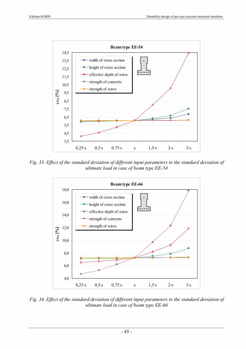
Kálmán KORIS Durability-design of pre-cast concrete structural members
- 45 -
Beam type EE-54
3,5
4,5
5,5
6,5
7,5
8,5
9,5
10,5
11,5
12,5
13,5
14,5
0,25·s 0,5·s 0,75·s s 1,5·s 2·s 3·s
νFu [
%]
width of cross section
height of cross section
effective depth of wires
strength of concrete
strength of wires
Fig. 33. Effect of the standard deviation of different input parameters to the standard deviation of ultimate load in case of beam type EE-54
Beam type EE-66
4,0
6,0
8,0
10,0
12,0
14,0
16,0
18,0
0,25·s 0,5·s 0,75·s s 1,5·s 2·s 3·s
νFu [
%]
width of cross section
height of cross section
effective depth of wires
strength of concrete
strength of wires
Fig. 34. Effect of the standard deviation of different input parameters to the standard deviation of ultimate load in case of beam type EE-66
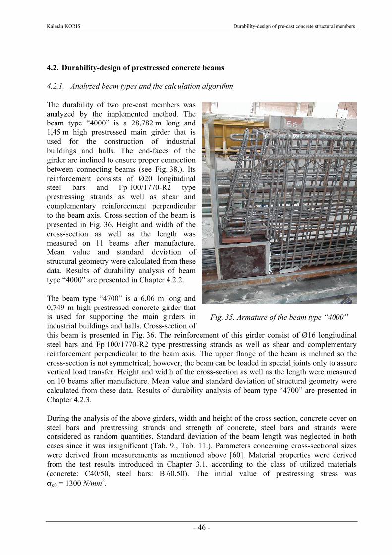
Kálmán KORIS Durability-design of pre-cast concrete structural members
- 46 -
4.2. Durability-design of prestressed concrete beams 4.2.1. Analyzed beam types and the calculation algorithm The durability of two pre-cast members was analyzed by the implemented method. The beam type “4000” is a 28,782 m long and 1,45 m high prestressed main girder that is used for the construction of industrial buildings and halls. The end-faces of the girder are inclined to ensure proper connection between connecting beams (see Fig. 38.). Its reinforcement consists of Ø20 longitudinal steel bars and Fp 100/1770-R2 type prestressing strands as well as shear and complementary reinforcement perpendicular to the beam axis. Cross-section of the beam is presented in Fig. 36. Height and width of the cross-section as well as the length was measured on 11 beams after manufacture. Mean value and standard deviation of structural geometry were calculated from these data. Results of durability analysis of beam type “4000” are presented in Chapter 4.2.2. The beam type “4700” is a 6,06 m long and 0,749 m high prestressed concrete girder that is used for supporting the main girders in industrial buildings and halls. Cross-section of this beam is presented in Fig. 36. The reinforcement of this girder consist of Ø16 longitudinal steel bars and Fp 100/1770-R2 type prestressing strands as well as shear and complementary reinforcement perpendicular to the beam axis. The upper flange of the beam is inclined so the cross-section is not symmetrical; however, the beam can be loaded in special joints only to assure vertical load transfer. Height and width of the cross-section as well as the length were measured on 10 beams after manufacture. Mean value and standard deviation of structural geometry were calculated from these data. Results of durability analysis of beam type “4700” are presented in Chapter 4.2.3. During the analysis of the above girders, width and height of the cross section, concrete cover on steel bars and prestressing strands and strength of concrete, steel bars and strands were considered as random quantities. Standard deviation of the beam length was neglected in both cases since it was insignificant (Tab. 9., Tab. 11.). Parameters concerning cross-sectional sizes were derived from measurements as mentioned above [60]. Material properties were derived from the test results introduced in Chapter 3.1. according to the class of utilized materials (concrete: C40/50, steel bars: B 60.50). The initial value of prestressing stress was σp0 = 1300 N/mm2.
Fig. 35. Armature of the beam type “4000”

Kálmán KORIS Durability-design of pre-cast concrete structural members
- 47 -
Fig. 36. Cross-sections of beams “4000” and “4700” Failure probability was calculated for both girders in different points of time. Selected times for the analysis were t = 10, 25, 50, 75 and 100 years. In each point of time 3 different values of the ambient relative humidity were considered. The examined cases were: RH = 50%, 65% and 80%. The initial value of imposed load (q0) was also changed during the analysis. For each beam, 5 different values were considered. Values q0 = 16, 18, 20, 22 and 24 kN/m were used for beam “4000” and q0 = 115, 120, 125, 130 and 135 kN/m were applied for beam “4700”. Current values of input parameters and the load effect were calculated as a function of time, relative humidity and initial imposed load by the method described in Chapter 3.2. Changes of geometrical sizes and material strengths with regard to the mean value and standard deviation are presented in Fig. 39., Fig. 40. and Fig. 41. in case of beam “4000”. Same diagrams for the beam “4700” are presented in Fig. 51., Fig. 52. and Fig. 53. The mean value of structural resistance was calculated by finite element method while its standard deviation was evaluated by stochastic finite element method using current values of input parameters. The implemented calculation method is described in Chapter 2.4. and 2.5. To perform the calculations, the computer software PFEM2008 (see Appendix A2) was developed using the Matlab® software package. The flowchart of the calculation process that was used by the PFEM2008 software is presented in Fig. 37. Using the mean value and standard deviation of structural resistance and current load effect, the probability of failure was calculated. Considering 5 different times, 3 humidity levels and 5 different values for initial imposed load, the number of runs was 5×3×5 = 75 for each beam. Charts for the durability-design were created using the evaluated failure probabilities. These charts and example for their use are presented in Chapters 4.2.2. and 4.2.3.
35
7,5
74,9
3×4
5 3
12,5
2
67,4
60
30
22
14 6
145
8 5
5 1
3×4
5
3
Beam “4000”
Beam “4700”

Kálmán KORIS Durability-design of pre-cast concrete structural members
- 48 -
Initial values of input parameters derived from measurements and material tests:
- material properties fi,0 - structural geometry xi,0 - initial prestress σp0 - imposed load q0
t = t0
Recalculating stiffness properties according to M–κ curve
Fi+1 = Fi + ΔF
No
ti+1 = ti + Δt
Calculation of prestress loss and current values of input parameters:
- material properties fi(t) - structural geometry xi(t) - effective prestress σpm(t) - design load p(t) = g(t) + q(t)
Evaluation of D from elastic stiffness properties (Ec·Ai, Ec·Ixi, Ec·Iyi)
Initial value of load intensity: F = F0
Evaluation of load vector: q = F·Φ Evaluation of stiffness matrix of the structure: K Solving the FE equation system: u = K-1· q
Structural failure occurred?
Yes
Calculation of mean value and standard deviation of structural resistance: pu, spu
Evaluation of the failure probability
t = tmax was reached?
Yes
End of analysis
No
Fig. 37. Flowchart of the calculation process

Kálmán KORIS Durability-design of pre-cast concrete structural members
- 49 -
4.2.2. Analysis of beam type “4000” Geometry of beam “4000” was evaluated by measurements on 11 fabricated samples. The result of measurements is presented in Tab. 9. Geometrical sizes without measuring result were taken from the plan of formwork. Standard deviation of effective height was calculated from the standard deviation of concrete cover which was about 10%.
Number of strands L hm bf,m
Mean value[mm] 27691 1442 604
Standard deviation [%] 0,028 0,533 1,1772+16
Tab. 9. Mean values and standard deviations of measured geometrical sizes for beam “4000” Material properties were derived from the test results introduced in Chapter 3.1. According to the class of utilized materials, the following strength values were used for the calculation: fc,m = 52,5 N/mm2, νfc = 6,4 %, fs,m = 647,5 N/mm2, νfs = 2,6 %, fp,m = 1930 N/mm2 and νfp = 1,4 %. The side view and the considered cross section of beam “4000” are presented in Fig. 38. An evenly distributed load (p = self weight + imposed load) was applied to the beam during the analysis.
Fig. 38. Side view and simplified cross section of beam type “4000”
L
Concrete: C40/50 Steel bars: 4Ø20+2Ø20 B60.50 Prestressing strands: 16+2 Fp-100/1770-R2
p
bf
ba
h a
b
h f
h
Side view Cross-section

Kálmán KORIS Durability-design of pre-cast concrete structural members
- 50 -
Changes of the mean values of concrete, steel bar and prestressing tendon strength as a function of time at a relative humidity level of RH = 65% are presented in Fig. 39. After 100 years, the decrease of strength is about 1,6% for all materials according to {15}. Change of the standard deviation of material strength in time at RH = 65% are demonstrated in Fig. 40. The increase of standard deviation after 100 years compared to the initial values is about 12,5% in case of concrete and about 9,7% in case of steel bars and tendons. Increase of the standard deviation of structural geometry at a humidity level of RH = 65% is presented in Fig. 41. The amount of increase compared to the initial values is about 4,9% after 100 years.
Change of steel bar strength
635
638
641
644
647
650
10 25 50 75 100Time [years]
f s,m
[N/m
m2 ]
Change of tendon strength
1880
1890
1900
1910
1920
1930
1940
10 25 50 75 100
Time [years]
f p,m
[N/m
m2 ]
Change of concrete strength
51,0
51,5
52,0
52,5
53,0
10 25 50 75 100Time [years]
f c,m
[N/m
m2 ]
Fig. 39. Change of the mean value of strength in case of different materials in time at RH=65%
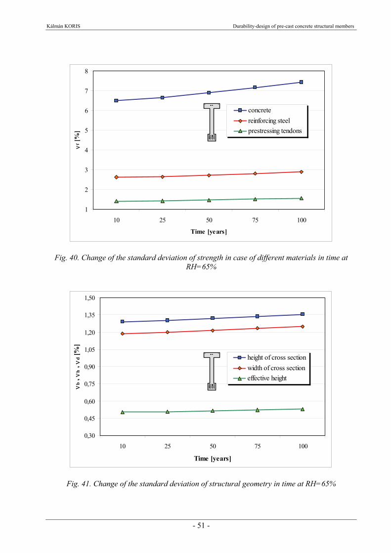
Kálmán KORIS Durability-design of pre-cast concrete structural members
- 51 -
1
2
3
4
5
6
7
8
10 25 50 75 100
Time [years]
νf [%
]
concretereinforcing steelprestressing tendons
Fig. 40. Change of the standard deviation of strength in case of different materials in time at RH=65%
0,30
0,45
0,60
0,75
0,90
1,05
1,20
1,35
1,50
10 25 50 75 100
Time [years]
νb ,
νh ,
νd [%
]
height of cross sectionwidth of cross sectioneffective height
Fig. 41. Change of the standard deviation of structural geometry in time at RH=65%

Kálmán KORIS Durability-design of pre-cast concrete structural members
- 52 -
1100
1200
1300
1400
1500
1600
1700
10 20 30 40 50 60 70 80 90 100
Time [years]
As ,
Ap [
mm
2 ]
steel bars
prestressing tendons
start of steel bar corrosion
start of tendon corrosion
Fig. 42. Change of cross-sectional area of steel bars and prestressing tendons in time at RH=65%
1100
1150
1200
1250
1300
10 20 30 40 50 60 70 80 90 100
Time [years]
As [
mm
2 ]
RH=50%
RH=65%
RH=80%
Fig. 43. Change of cross-sectional area of steel bars in time at different relative humidity levels

Kálmán KORIS Durability-design of pre-cast concrete structural members
- 53 -
The decrease of cross-sectional areas of steel bars and prestressing tendons due to carbonation induced corrosion at a relative humidity level of RH = 65% is presented in Fig. 42. Corrosion of steel bars starts after 42 years while tendons in the lowest position start to corrode after 71 years only due to the larger concrete cover on them. The amount of area loss is about 10,5% in case of steel bars and 1,2% in case of tendons after 100 years. The effect of the ambient relative humidity on the process of carbonation and corrosion is demonstrated in Fig. 43. In case of lower humidity levels, the process of carbonation is faster so the corrosion of steel bars starts earlier. Higher levels of humidity result in slower carbonation thus corrosion starts later. However, higher level of humidity also means higher rate of corrosion after the depassivation. Changes of process parameters described above were considered during the analysis of the beam “4000”. The effect of elapsed time and humidity level on the behavior of the cross-section is demonstrated by the corresponding bending moment-curvature (M-κ) diagrams (Fig. 44.). It can be stated that the mean value of load carrying capacity decreases with the decrease of humidity level and progress of time. Mean value (pu,m) and standard deviation (νpu) of structural resistance at different times and relative humidity levels were calculated by SFEM as described in Chapter 4.2.1. Results concerning mean value of the resistance are presented in Fig. 45. Standard deviation of resistance under different conditions is presented in Fig. 46.
0
1000
2000
3000
4000
5000
0 0,005 0,01 0,015 0,02 0,025κ [1/m]
M [k
N/m
]
t=10 years, RH=50%t=10 years, RH=80%
t=100 years, RH=50%t=100 years, RH=80%
Fig. 44. Bending moment – curvature diagrams for beam type “4000” at different ages and humidity levels

Kálmán KORIS Durability-design of pre-cast concrete structural members
- 54 -
51,5
52,0
52,5
53,0
53,5
54,0
54,5
55,0
10 20 30 40 50 60 70 80 90 100
Time [years]
p u,m
[kN
]
RH=50%RH=65%RH=80%
Fig. 45. Change of mean value of structural resistance in time at different RH levels
4
5
6
7
8
9
10
10 20 30 40 50 60 70 80 90 100
Time [years]
νpu [
%]
RH=50%RH=65%RH=80%
Fig. 46. Change of standard deviation of structural resistance in time at different RH levels

Kálmán KORIS Durability-design of pre-cast concrete structural members
- 55 -
According to Fig. 45. the mean value of resistance decreases in time. The rate of decrease is higher in case of lower levels of relative humidity. Standard deviation of structural resistance increases in time but the effect of humidity is opposite than in case of mean values. The value of standard deviation is increasing with the growth of humidity level. The changes of mean value and standard deviation of load effect over a period of 100 years are presented in Fig. 47. The increase of the mean value of design load (pm) is about 13,4% after 100 years. The standard deviation of load effect is increasing due to the increasing variation of geometrical sizes; however, relative standard deviation (νp) is decreasing in time because the growth rate of mean value is higher. The probability of failure as a function of time, relative humidity and initial imposed load is presented in Fig. 48. Different diagrams refer to different levels of humidity. The horizontal axis refers to the time elapsed since the manufacture of the beam, while the probability of failure is displayed on the vertical axis. Different curves within one diagram refer to different initial imposed load values. We can state that the probability of failure is
- increasing as time is passing by, - increasing as the level of relative humidity is increasing, - increasing as the initial value of imposed load is increasing.
These trends were of course theoretically expected but the results of analysis could verify the expectations. The effect of relative humidity as environmental condition on the probability of failure in case of initial imposed load q0 = 20 kN/m is demonstrated in Fig. 49. Detailed results of this comparison are presented in Tab. 10. including mean values and standard deviations of structural resistance (pu), load (p) and the summated distribution (pu – p), the safety index (β) and the probability of failure. Use of the presented diagrams (Fig. 48.) for the purposes of durability-design is demonstrated by numerical example in case of beam “4000” in Chapter 4.2.4.
32
33
34
35
36
37
38
10 25 40 55 70 85 100Time [years]
p m [k
N]
4,0
4,5
5,0
5,5
6,0
10 25 40 55 70 85 100Time [years]
νp [%
]
Fig. 47. Change of the mean value and standard deviation of loads in time
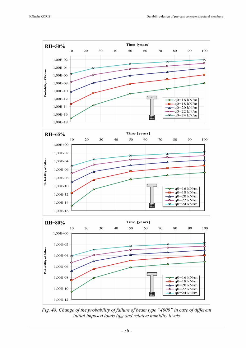
Kálmán KORIS Durability-design of pre-cast concrete structural members
- 56 -
1,00E-18
1,00E-16
1,00E-14
1,00E-12
1,00E-10
1,00E-08
1,00E-06
1,00E-04
1,00E-02
10 20 30 40 50 60 70 80 90 100
Time [years]Pr
obab
ility
of f
ailu
re
q0=16 kN/mq0=18 kN/mq0=20 kN/mq0=22 kN/mq0=24 kN/m
1,00E-16
1,00E-14
1,00E-12
1,00E-10
1,00E-08
1,00E-06
1,00E-04
1,00E-02
1,00E+0010 20 30 40 50 60 70 80 90 100
Time [years]
Prob
abili
ty o
f fai
lure
q0=16 kN/mq0=18 kN/mq0=20 kN/mq0=22 kN/mq0=24 kN/m
1,00E-12
1,00E-10
1,00E-08
1,00E-06
1,00E-04
1,00E-02
1,00E+0010 20 30 40 50 60 70 80 90 100
Time [years]
Prob
abili
ty o
f fai
lure
q0=16 kN/mq0=18 kN/mq0=20 kN/mq0=22 kN/mq0=24 kN/m
Fig. 48. Change of the probability of failure of beam type “4000” in case of different
initial imposed loads (q0) and relative humidity levels
RH=50%
RH=65%
RH=80%
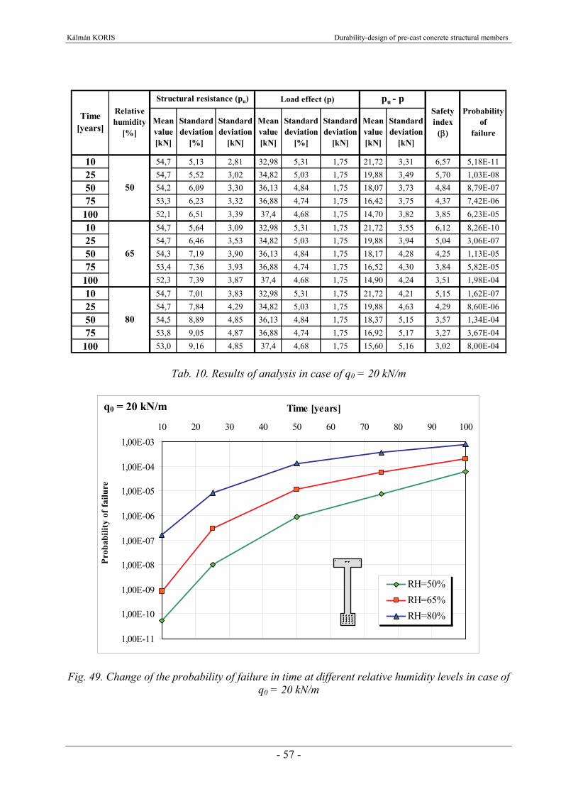
Kálmán KORIS Durability-design of pre-cast concrete structural members
- 57 -
Mean value [kN]
Standard deviation
[%]
Standard deviation
[kN]
Mean value [kN]
Standard deviation
[%]
Standard deviation
[kN]
Mean value [kN]
Standard deviation
[kN]
10 54,7 5,13 2,81 32,98 5,31 1,75 21,72 3,31 6,57 5,18E-1125 54,7 5,52 3,02 34,82 5,03 1,75 19,88 3,49 5,70 1,03E-0850 54,2 6,09 3,30 36,13 4,84 1,75 18,07 3,73 4,84 8,79E-0775 53,3 6,23 3,32 36,88 4,74 1,75 16,42 3,75 4,37 7,42E-06
100 52,1 6,51 3,39 37,4 4,68 1,75 14,70 3,82 3,85 6,23E-05
10 54,7 5,64 3,09 32,98 5,31 1,75 21,72 3,55 6,12 8,26E-1025 54,7 6,46 3,53 34,82 5,03 1,75 19,88 3,94 5,04 3,06E-0750 54,3 7,19 3,90 36,13 4,84 1,75 18,17 4,28 4,25 1,13E-0575 53,4 7,36 3,93 36,88 4,74 1,75 16,52 4,30 3,84 5,82E-05
100 52,3 7,39 3,87 37,4 4,68 1,75 14,90 4,24 3,51 1,98E-04
10 54,7 7,01 3,83 32,98 5,31 1,75 21,72 4,21 5,15 1,62E-0725 54,7 7,84 4,29 34,82 5,03 1,75 19,88 4,63 4,29 8,60E-0650 54,5 8,89 4,85 36,13 4,84 1,75 18,37 5,15 3,57 1,34E-0475 53,8 9,05 4,87 36,88 4,74 1,75 16,92 5,17 3,27 3,67E-04
100 53,0 9,16 4,85 37,4 4,68 1,75 15,60 5,16 3,02 8,00E-04
Safety index
(β)
Probabilityof
failure
pu - pLoad effect (p)
80
Structural resistance (pu)
Time [years]
Relative humidity
[%]
50
65
Tab. 10. Results of analysis in case of q0 = 20 kN/m
1,00E-11
1,00E-10
1,00E-09
1,00E-08
1,00E-07
1,00E-06
1,00E-05
1,00E-04
1,00E-0310 20 30 40 50 60 70 80 90 100
Time [years]
Prob
abili
ty o
f fai
lure
RH=50%RH=65%RH=80%
Fig. 49. Change of the probability of failure in time at different relative humidity levels in case of q0 = 20 kN/m
q0 = 20 kN/m

Kálmán KORIS Durability-design of pre-cast concrete structural members
- 58 -
Results on the beam “4000” were also compared to the Eurocode 2 (EC2) standard [21]. The concrete cover on the longitudinal steel bars is a = 40 mm. A cyclic wet and dry environment with relative humidity level RH = 80% was assumed for the analysis. These conditions refer to exposure class XC4 according to [21]. Considering exposure class XC4 and the concrete cover a = 40 mm, the structure belongs to the structural class S6 with a service life of 100 years [21]. The bending moment resistance calculated according to the principles of EC2 and using the above conditions is MRd = 3611,3 kNm. The maximum design value of imposed load can be calculated from the bending moment resistance:
m/kN,,,
,gLM
q dRd
EC.d 572613116827
336118822 =−⋅=−
⋅=
The characteristic value of imposed load considering the safety factor γq = 1,5: qk.EC = qd.EC / 1,5 = 17,72 kN/m Using EC2, the mean value of imposed load assuming normal distribution and a relative standard deviation νq = 5% can be expressed in the following form [56]:
qm.EC = q
EC.k
,q
ν⋅+ 64511= 16,37 kN/m
Let us now evaluate the maximum applicable imposed load according to the introduced method. It is supposed that the probability of failure is 10-4 according to the regulations of EC2. Using the third chart in Fig. 48. (considering RH = 80% and t = 100 years) the initial mean value of imposed load can be: qm = 18,13 kN/m This value is about 10% higher than the value obtained from calculation according to EC2. Comparing the design values, we get the same result. Design value of imposed load in case of the implemented method is: qd = 1,5·qm·(1+1,645·νq) = 29,4 kN/m The difference between the design values is:
=−⋅ 100100EC.d
d
qq 10,7%
Considering the result above, it can be stated that more economical design can be achieved by the use of the implemented durability-design method compared to EC2.
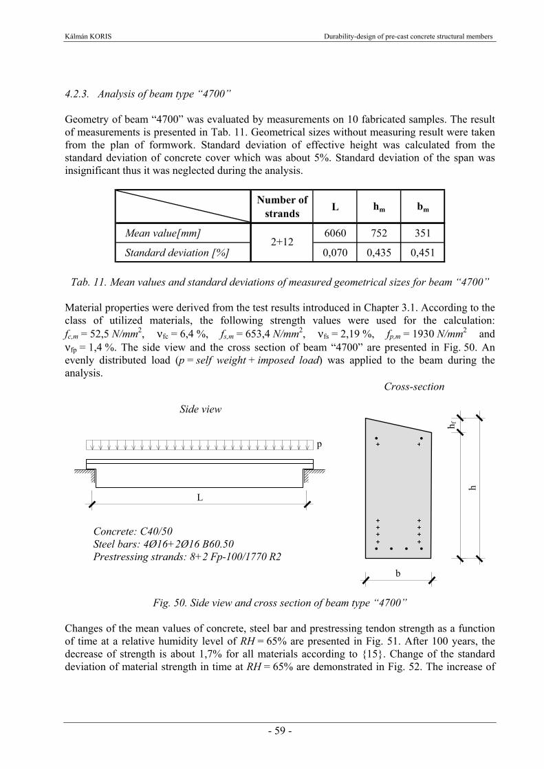
Kálmán KORIS Durability-design of pre-cast concrete structural members
- 59 -
4.2.3. Analysis of beam type “4700” Geometry of beam “4700” was evaluated by measurements on 10 fabricated samples. The result of measurements is presented in Tab. 11. Geometrical sizes without measuring result were taken from the plan of formwork. Standard deviation of effective height was calculated from the standard deviation of concrete cover which was about 5%. Standard deviation of the span was insignificant thus it was neglected during the analysis.
Number of
strands L hm bm
Mean value[mm] 6060 752 351
Standard deviation [%] 0,070 0,435 0,4512+12
Tab. 11. Mean values and standard deviations of measured geometrical sizes for beam “4700” Material properties were derived from the test results introduced in Chapter 3.1. According to the class of utilized materials, the following strength values were used for the calculation: fc,m = 52,5 N/mm2, νfc = 6,4 %, fs,m = 653,4 N/mm2, νfs = 2,19 %, fp,m = 1930 N/mm2 and νfp = 1,4 %. The side view and the cross section of beam “4700” are presented in Fig. 50. An evenly distributed load (p = self weight + imposed load) was applied to the beam during the analysis.
Fig. 50. Side view and cross section of beam type “4700”
Changes of the mean values of concrete, steel bar and prestressing tendon strength as a function of time at a relative humidity level of RH = 65% are presented in Fig. 51. After 100 years, the decrease of strength is about 1,7% for all materials according to {15}. Change of the standard deviation of material strength in time at RH = 65% are demonstrated in Fig. 52. The increase of
Cross-section
b
h f
h
L
Concrete: C40/50 Steel bars: 4Ø16+2Ø16 B60.50 Prestressing strands: 8+2 Fp-100/1770 R2
p
Side view
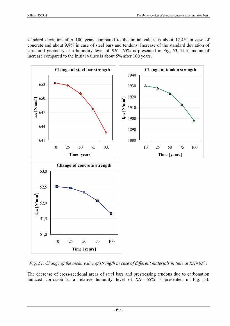
Kálmán KORIS Durability-design of pre-cast concrete structural members
- 60 -
standard deviation after 100 years compared to the initial values is about 12,4% in case of concrete and about 9,8% in case of steel bars and tendons. Increase of the standard deviation of structural geometry at a humidity level of RH = 65% is presented in Fig. 53. The amount of increase compared to the initial values is about 5% after 100 years.
Change of steel bar strength
641
644
647
650
653
10 25 50 75 100Time [years]
f s,m
[N/m
m2 ]
Change of tendon strength
1880
1890
1900
1910
1920
1930
1940
10 25 50 75 100
Time [years]
f p,m
[N/m
m2 ]
Change of concrete strength
51,0
51,5
52,0
52,5
53,0
10 25 50 75 100
Time [years]
f c,m
[N/m
m2 ]
Fig. 51. Change of the mean value of strength in case of different materials in time at RH=65% The decrease of cross-sectional areas of steel bars and prestressing tendons due to carbonation induced corrosion at a relative humidity level of RH = 65% is presented in Fig. 54.

Kálmán KORIS Durability-design of pre-cast concrete structural members
- 61 -
1
2
3
4
5
6
7
8
10 25 50 75 100
Time [years]
νf [%
] concretereinforcing steelprestressing tendons
Fig. 52. Change of the standard deviation of strength in case of different materials in time at RH=65%
0,38
0,40
0,42
0,44
0,46
0,48
0,50
0,52
0,54
10 25 50 75 100
Time [years]
νb ,
νh ,
νd [%
]
height of cross sectionwidth of cross sectioneffective height
Fig. 53. Change of the standard deviation of structural geometry in time at RH=65%
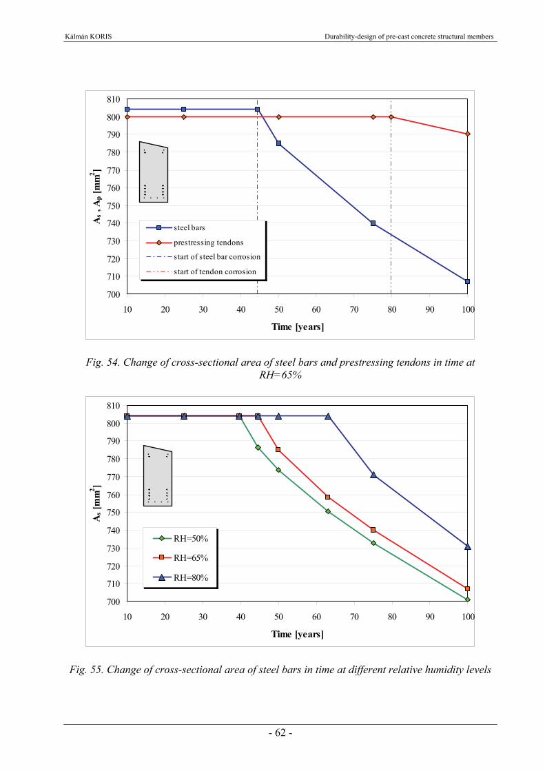
Kálmán KORIS Durability-design of pre-cast concrete structural members
- 62 -
700
710
720
730
740
750
760
770
780
790
800
810
10 20 30 40 50 60 70 80 90 100
Time [years]
As ,
Ap [
mm
2 ]
steel bars
prestressing tendons
start of steel bar corrosion
start of tendon corrosion
Fig. 54. Change of cross-sectional area of steel bars and prestressing tendons in time at RH=65%
700
710
720
730
740
750
760
770
780
790
800
810
10 20 30 40 50 60 70 80 90 100
Time [years]
As [
mm
2 ]
RH=50%
RH=65%
RH=80%
Fig. 55. Change of cross-sectional area of steel bars in time at different relative humidity levels

Kálmán KORIS Durability-design of pre-cast concrete structural members
- 63 -
Corrosion of steel bars starts after 44,5 years while tendons in the lowest position start to corrode after 80 years only due to the larger concrete cover on them. The amount of area loss is about 13,8% in case of steel bars and 1,2% in case of tendons after 100 years. The effect of the ambient relative humidity on the process of carbonation and corrosion is demonstrated in Fig. 55. In case of lower humidity levels, the process of carbonation is faster so the corrosion of steel bars starts earlier. Higher levels of humidity result in slower carbonation thus corrosion starts later. However higher level of humidity also means higher rate of corrosion after the depassivation in case of this beam, too. Changes of process parameters described above were considered during the analysis of the beam “4700”. The effect of elapsed time and humidity level on the behavior of the cross-section is demonstrated by the corresponding bending moment-curvature (M-κ) diagrams (Fig. 56.). It can be again stated that the mean value of load carrying capacity decreases with the decrease of humidity level and progress of time. Mean value (pu,m) and standard deviation (νpu) of structural resistance at different times and relative humidity levels were calculated by SFEM as described in Chapter 4.2.1. Results concerning mean value of the resistance are presented in Fig. 57. Standard deviation of resistance under different conditions is presented in Fig. 58.
0
200
400
600
800
1000
1200
0 0,005 0,01 0,015 0,02κ [1/m]
M [k
N/m
]
t=10 years, RH=50%t=10 years, RH=80%
t=100 years, RH=50%t=100 years, RH=80%
Fig. 56. Bending moment – curvature diagrams for beam type “4700” at different ages and humidity levels

Kálmán KORIS Durability-design of pre-cast concrete structural members
- 64 -
232
234
236
238
240
242
244
246
248
250
10 20 30 40 50 60 70 80 90 100
Time [years]
p u,m
[kN
]
RH=50%RH=65%RH=80%
Fig. 57. Change of the mean value of structural resistance in time at different relative humidity levels
1,5
2,0
2,5
3,0
3,5
4,0
4,5
5,0
5,5
6,0
6,5
10 20 30 40 50 60 70 80 90 100
Time [years]
νpu [
%]
RH=50%RH=65%RH=80%
Fig. 58. Change of the standard deviation of structural resistance in time at different relative humidity levels
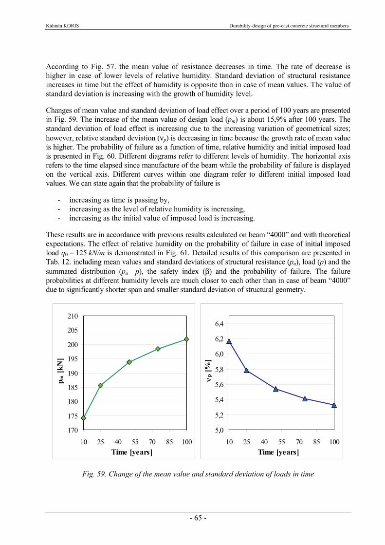
Kálmán KORIS Durability-design of pre-cast concrete structural members
- 65 -
According to Fig. 57. the mean value of resistance decreases in time. The rate of decrease is higher in case of lower levels of relative humidity. Standard deviation of structural resistance increases in time but the effect of humidity is opposite than in case of mean values. The value of standard deviation is increasing with the growth of humidity level. Changes of mean value and standard deviation of load effect over a period of 100 years are presented in Fig. 59. The increase of the mean value of design load (pm) is about 15,9% after 100 years. The standard deviation of load effect is increasing due to the increasing variation of geometrical sizes; however, relative standard deviation (νp) is decreasing in time because the growth rate of mean value is higher. The probability of failure as a function of time, relative humidity and initial imposed load is presented in Fig. 60. Different diagrams refer to different levels of humidity. The horizontal axis refers to the time elapsed since manufacture of the beam while the probability of failure is displayed on the vertical axis. Different curves within one diagram refer to different initial imposed load values. We can state again that the probability of failure is
- increasing as time is passing by, - increasing as the level of relative humidity is increasing, - increasing as the initial value of imposed load is increasing.
These results are in accordance with previous results calculated on beam “4000” and with theoretical expectations. The effect of relative humidity on the probability of failure in case of initial imposed load q0 = 125 kN/m is demonstrated in Fig. 61. Detailed results of this comparison are presented in Tab. 12. including mean values and standard deviations of structural resistance (pu), load (p) and the summated distribution (pu – p), the safety index (β) and the probability of failure. The failure probabilities at different humidity levels are much closer to each other than in case of beam “4000” due to significantly shorter span and smaller standard deviation of structural geometry.
170
175
180
185
190
195
200
205
210
10 25 40 55 70 85 100Time [years]
p m [k
N]
5,0
5,2
5,4
5,6
5,8
6,0
6,2
6,4
10 25 40 55 70 85 100Time [years]
νp [%
]
Fig. 59. Change of the mean value and standard deviation of loads in time
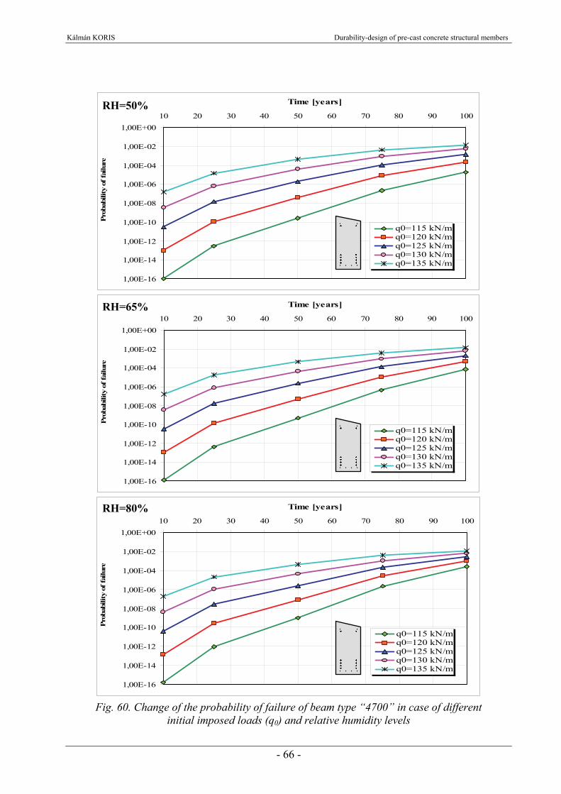
Kálmán KORIS Durability-design of pre-cast concrete structural members
- 66 -
1,00E-16
1,00E-14
1,00E-12
1,00E-10
1,00E-08
1,00E-06
1,00E-04
1,00E-02
1,00E+0010 20 30 40 50 60 70 80 90 100
Time [years]Pr
obab
ility
of f
ailu
re
q0=115 kN/mq0=120 kN/mq0=125 kN/mq0=130 kN/mq0=135 kN/m
1,00E-16
1,00E-14
1,00E-12
1,00E-10
1,00E-08
1,00E-06
1,00E-04
1,00E-02
1,00E+0010 20 30 40 50 60 70 80 90 100
Time [years]
Prob
abili
ty o
f fai
lure
q0=115 kN/mq0=120 kN/mq0=125 kN/mq0=130 kN/mq0=135 kN/m
1,00E-16
1,00E-14
1,00E-12
1,00E-10
1,00E-08
1,00E-06
1,00E-04
1,00E-02
1,00E+0010 20 30 40 50 60 70 80 90 100
Time [years]
Prob
abili
ty o
f fai
lure
q0=115 kN/mq0=120 kN/mq0=125 kN/mq0=130 kN/mq0=135 kN/m
Fig. 60. Change of the probability of failure of beam type “4700” in case of different
initial imposed loads (q0) and relative humidity levels
RH=50%
RH=65%
RH=80%

Kálmán KORIS Durability-design of pre-cast concrete structural members
- 67 -
Mean value [kN]
Standard deviation
[%]
Standard deviation
[kN]
Mean value [kN]
Standard deviation
[%]
Standard deviation
[kN]
Mean value [kN]
Standard deviation
[kN]
10 248,7 1,70 4,23 174,1 6,168 10,738 74,60 11,54 6,46 2,92E-1125 248,6 1,76 4,37 185,7 5,785 10,743 62,90 11,60 5,42 1,41E-0850 245,5 1,85 4,54 193,9 5,540 10,742 51,60 11,66 4,42 1,92E-0675 240,4 2,62 6,29 198,5 5,410 10,739 41,90 12,45 3,37 1,11E-04
100 234,3 3,22 7,54 201,8 5,323 10,742 32,50 13,12 2,48 1,42E-03
10 248,6 1,73 4,30 174,1 6,168 10,738 74,50 11,57 6,44 3,37E-1125 248,5 1,83 4,55 185,7 5,785 10,743 62,80 11,67 5,38 1,74E-0850 246,3 2,12 5,23 193,9 5,540 10,742 52,40 11,95 4,39 2,22E-0675 241,5 3,03 7,32 198,5 5,410 10,739 43,00 12,99 3,31 1,29E-04
100 235,2 4,36 10,25 201,8 5,323 10,742 33,40 14,85 2,25 2,14E-03
10 248,5 1,75 4,35 174,1 6,168 10,738 74,40 11,59 6,42 3,84E-1125 248,4 1,98 4,93 185,7 5,785 10,743 62,70 11,82 5,31 2,61E-0850 247,7 2,50 6,19 193,9 5,540 10,742 53,80 12,40 4,34 2,61E-0675 243,9 4,03 9,82 198,5 5,410 10,739 45,40 14,55 3,12 2,11E-04
100 238,9 6,08 14,53 201,8 5,323 10,742 37,10 18,07 2,05 2,68E-03
80
Structural resistance (pu)
Time [years]
Relative humidity
[%]
50
65
Safety index
(β)
Probabilityof
failure
pu - pLoad effect (p)
Tab. 12. Results of analysis in case of q0 = 125 kN/m
1,00E-11
1,00E-10
1,00E-09
1,00E-08
1,00E-07
1,00E-06
1,00E-05
1,00E-04
1,00E-03
1,00E-0210 20 30 40 50 60 70 80 90 100
Time [years]
Prob
abili
ty o
f fai
lure
RH=50%
RH=65%
RH=80%
Fig. 61. Change of the probability of failure in time at different relative humidity levels in case of q0 = 125 kN/m
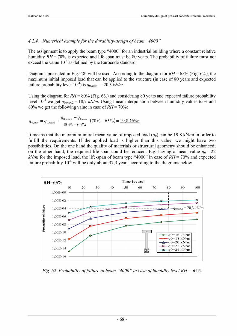
Kálmán KORIS Durability-design of pre-cast concrete structural members
- 68 -
4.2.4. Numerical example for the durability-design of beam “4000” The assignment is to apply the beam type “4000” for an industrial building where a constant relative humidity RH = 70% is expected and life-span must be 80 years. The probability of failure must not exceed the value 10-4 as defined by the Eurocode standard. Diagrams presented in Fig. 48. will be used. According to the diagram for RH = 65% (Fig. 62.), the maximum initial imposed load that can be applied to the structure (in case of 80 years and expected failure probability level 10-4) is q0,max,1 = 20,3 kN/m. Using the diagram for RH = 80% (Fig. 63.) and considering 80 years and expected failure probability level 10-4 we get q0,max,2 = 18,7 kN/m. Using linear interpolation between humidity values 65% and 80% we get the following value in case of RH = 70%:
( ) =−−−
+= %%%%
qqqq max,,max,,
max,,max, 65706580
1020100 19,8 kN/m
It means that the maximum initial mean value of imposed load (q0) can be 19,8 kN/m in order to fulfill the requirements. If the applied load is higher than this value, we might have two possibilities. On the one hand the quality of materials or structural geometry should be enhanced; on the other hand, the required life-span could be reduced. E.g. having a mean value q0 = 22 kN/m for the imposed load, the life-span of beam type “4000” in case of RH = 70% and expected failure probability 10-4 will be only about 37,3 years according to the diagrams below.
1,00E-16
1,00E-14
1,00E-12
1,00E-10
1,00E-08
1,00E-06
1,00E-04
1,00E-02
1,00E+0010 20 30 40 50 60 70 80 90 100
Time [years]
Prob
abili
ty o
f fai
lure
q0=16 kN/mq0=18 kN/mq0=20 kN/mq0=22 kN/mq0=24 kN/m
Fig. 62. Probability of failure of beam “4000” in case of humidity level RH = 65%
RH=65%
q0,max,1 = 20,3 kN/m

Kálmán KORIS Durability-design of pre-cast concrete structural members
- 69 -
1,00E-12
1,00E-10
1,00E-08
1,00E-06
1,00E-04
1,00E-02
1,00E+0010 20 30 40 50 60 70 80 90 100
Time [years]Pr
obab
ility
of f
ailu
re
q0=16 kN/mq0=18 kN/mq0=20 kN/mq0=22 kN/mq0=24 kN/m
Fig. 63. Probability of failure of beam “4000” in case of humidity level RH = 80%
4.2.5. Durability analysis of existing structural members Besides the durability-design of new structural members, the presented method (see Chapters 2. and 3.) is also suitable for the analysis of existing structural elements. The expectable service life or the necessary strengthening of old or damaged structural members can be designed by measuring the current values of structural geometry and strength of materials (preferably by non-destructive methods) and by applying the described design method. This kind of analysis is demonstrated by the following numerical example. Let us suppose that we have to analyze a set of beams type “4000” (see Chapter 4.2.1.) that are already 50 years old. The relative ambient humidity level is RH=65%, the initial value of imposed load was q0 = 20 kN/m and the service life (considering popt=10-4) of the beams is 87 years according to the original calculations. Put the case that we measure the concrete strength of beams by Schmidt-hammer and we get a mean value fc,m = 52,45 N/mm2 and a standard deviation sfc = 3,4 N/mm2. These values slightly differ from the values that were predicted by the method described in Chapter 3.2.3. (see also Fig. 39. and Fig. 40.). Using the results of non-destructive concrete strength test, values of some process parameters in equations {15} and {16} can be refined to get more exact numerical results:
− The time period t0 in which the strength of the material decreases to zero can be modified from 500 years to 814 years,
− the value of constant b can be modified from 1,5 to 1,0 and − the value of constant k can be modified from 1,0 to 1,35.
Using these modified parameters, the numerical analysis will deliver the same mean value and standard deviation of concrete strength as we derived from non-destructive test at the age of 50 years. The effect of the modified process parameters on the failure probability of beam “4000” is
RH=80%
q0,max,2 = 18,7 kN/m
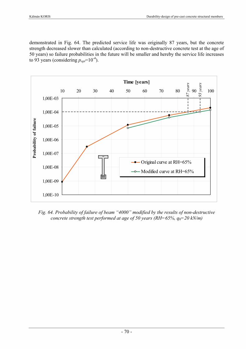
Kálmán KORIS Durability-design of pre-cast concrete structural members
- 70 -
demonstrated in Fig. 64. The predicted service life was originally 87 years, but the concrete strength decreased slower than calculated (according to non-destructive concrete test at the age of 50 years) so failure probabilities in the future will be smaller and hereby the service life increases to 93 years (considering popt=10-4).
1,00E-10
1,00E-09
1,00E-08
1,00E-07
1,00E-06
1,00E-05
1,00E-04
1,00E-0310 20 30 40 50 60 70 80 90 100
Time [years]
Prob
abili
ty o
f fai
lure
Original curve at RH=65%
Modified curve at RH=65%
Fig. 64. Probability of failure of beam “4000” modified by the results of non-destructive concrete strength test performed at age of 50 years (RH=65%, q0=20 kN/m)
87 y
ears
93 y
ears

Kálmán KORIS Durability-design of pre-cast concrete structural members
- 71 -
5. NEW RESULTS OF THE PHD THESIS New result #1. I developed a method based on probabilistic approach for the durability-design of prefabricated concrete structural members [34], [35]. This method can predict the probability of failure of the members at any given point of time. The deterioration of material strengths and geometrical sizes, the effect of carbonation induced corrosion as well as the change of load effect in time can be taken into account during the analysis. Random input parameters that are considered by the developed method are the strength of concrete, steel bars and prestressing tendons, the height and width of cross section, effective height of steel bars and tendons and the load effect. New result #2. I compared the standard deviation of load carrying capacity of prestressed concrete beams derived from bending test results to the results of numerical analyses. I proved by this comparison that the developed method is appropriate for the analysis of the standard deviation of load carrying capacity in case of pre-cast concrete structural members [37]. I demonstrated that results of the numerical analysis can be used for practical purposes if the values of input parameters are derived from material test results and geometry measurements on the corresponding members. New result #3. I performed parametric numerical analyses on pre-cast, prestressed concrete beams with the following results [37]: a.) I determined the effect of standard deviations of different input parameters (height and
width of cross-section, effective depth of tendons, strength of concrete and tendons) on the standard deviation of load carrying capacity of examined beams. The influence of the standard deviations of effective depth and concrete strength is the most significant, while change of the standard deviation of tendon strength has the least influence on the standard deviation of load carrying capacity in case of all examined beam types.
b.) I proved that the failure probability of pre-cast, prestressed concrete beams is increasing as
time is passing by; it is increasing as the level of relative humidity is increasing and it is increasing as the initial value of imposed load is increasing. I demonstrated the increase rate of failure probability as a function of different parameters graphically. Durability-design of examined girders can be performed by the presented charts.

Kálmán KORIS Durability-design of pre-cast concrete structural members
- 72 -
c.) I proved that the application of the presented method results in a more economic design
(higher load carrying capacity or smaller member sizes) of the examined pre-cast, prestressed concrete beams than the use of the relevant Eurocode 2 standard.
d.) I proved that the presented method can be efficiently applied for the durability analysis of
existing pre-cast, prestressed concrete members using geometry measurements and material tests on the examined members.
Kálmán KORIS Durability-design of pre-cast concrete structural members
- 73 -
6. POSSIBLE ENHANCEMENTS OF THE METHOD The implemented stochastic finite element method proved to be adequate for the evaluation of the scatter of load carrying capacity if input parameters are properly given. However the described method can be improved in order to increase the accuracy of the life-span estimation. Some possible enhancements of the method are listed below. Knowing the exact process parameters is one of the most important factors for a proper probabilistic analysis. Initial values of these parameters can be derived from the result of quality control in case of pre-cast concrete members but their changes in time can be only approximately described. Calculation method of the process parameters in a given point of time should be verified by measurements on existing concrete members of different age, exposed to different environmental conditions. Evaluation of concrete and steel strength, level of carbonation and corrosion, the amount of concrete cover loss under actual conditions could provide information for more accurate analysis. Deteriorations, such as chloride or frost induced damage (with or without de-icing agent) could be considered during the analysis to improve the adequacy of results [46]. This would be especially important in case of pre-cast members for traffic infrastructure (e.g. prefabricated bridge girders) [32] or for industrial buildings under aggressive environmental conditions. As it was outlined in Chapter 4.1.2. a more accurate method for the calculation of the load carrying capacity should be used considering subsidence of the stress strain curve of materials. This way, the mean value of structural resistance could be calculated more precisely to give a better estimate for the probability of failure. The possibility of shear failure and other failure mechanisms for reinforced or prestressed concrete members, as well as the serviceability limit states, could be considered to provide a complex analysis for members. The effect of shear and torsion could be considered by the application of Thimosenko beam elements in the FE calculation. The behavior of reinforced concrete beams in case of combined actions (compression, bending, shear, torsion) could be, for example, described by the methods proposed in [27], [31], [32] or [43]. The proper stochastic distributions of structural resistance and load effect could be considered during the evaluation of failure probability. The structural resistance of reinforced concrete members can be, for example, described by the Weibull distribution [28], [30], [45], [71]. In case of the load effect, self weight can be described by lognormal distribution while type I. extreme value distribution can be used for imposed loads [45].

Kálmán KORIS Durability-design of pre-cast concrete structural members
- 74 -
7. REFERENCES [1] Al-Harthy, A. S.; Frangopol, D. M.: Reliability Assessment of Prestressed Concrete Beams;
Journal of Structural Engineering, Vol. 120. No. 1, 1992. [2] Almási J.: Application of mathematical statistics in the analysis of R. C. and P. C.
structures by the method of Finite Elements; FIP VIII Congress London, 1978. [3] Almási J.: Adatok a vasbeton oszlop-keresztmetszetek véletlen geometriai eltéréséhez;
Mélyépítéstudományi Szemle, XXXVII. évfolyam 9. szám, 1987. [4] Ang, A. H.-S.; Amin, M.: Safety Factors and Probability in Structural Design; Proceedings
of the American Society of Civil Engineers, Journal of the Structural Division, July 1969. [5] Augusti, G.; Baratta, A.; Casciati, F.: Probabilistic Methods in Structural Engineering;
Taylor & Francis, 1984. [6] Balázs L. Gy.: A tartósság fogalma és növelésének módszerei; Betonszerkezetek tartóssága.
Szerkesztők: Balázs Gy.; Balázs L. Gy., p.7-19, Műegyetemi Kiadó, Budapest, 2008. [7] Belytschko, T.; Liu, W. K.; Mani, A.: Random Field Finite Elements; International Journal
for Numerical Methods in Engineering, Vol. 23., p.1831-1845, John Wiley & Sons 1986. [8] Bergmeister, K.; Novák, D.; Pukl, R.: SARA: An advanced engineering tool for reliability
assessment of concrete structures; Proceedings of the Second International Conference on Structural Engineering, Mechanics and Computation, Capetown, 5-7 July 2004.
[9] Besterfield, G. H.; Liu, W. K.; Lawrence, M. A.; Belytschko, T. B.: Brittle Fracture
Reliability by Probabilistic Finite Elements; Journal of Engineering Mechanics, Vol. 116, No. 3, March 1990.
[10] Biondini, F.; Bontempi, F.; Frangopol, D. M.; Malerba, P. G.: Lifetime Nonlinear Analysis
of Concrete Structures under Uncertainty; IABMAS ’06 - 3rd International Conference on Bridge Maintenance, Safety and Management, Porto, July 16-19, 2006.
[11] Bojtár I.; Gáspár Zs.: Végeselem-módszer építőmérnököknek; TERC, Budapest, 2003. [12] Bolotin, V. V.: Statisztikai módszerek a szerkezetek mechanikájában; Műszaki
Könyvkiadó, 1970. [13] Dallhaus, F.: Stochastische Untersuchungen von Silobeanspruchungen; Schriftenreihe des
Instituts für Massivbau und Baustofftechnologie, Heft 25, Universität Karlsruhe, 1995. [14] Dasgupta, G.; Yip, S.: Stochastic Strain-Displacement Matrices for Finite Elements with
Random Constitution; ICOSSAR ’89 - 5th International Conference on Structural Safety and Reliability, 1989.

Kálmán KORIS Durability-design of pre-cast concrete structural members
- 75 -
[15] Deodatis, G.: Bounds on Response Variability of Stochastic Finite Element Systems;
Journal of Engineering Mechanics, Vol. 116, No. 3, March 1990. [16] Deodatis, G.: Weighted Integral Method - I: Stochastic Stiffness Matrix; Journal of
Engineering Mechanics, Vol. 117, No. 8, August 1991. [17] Eibl, J.; Häußler, U.; Retzepis, I.: Zur numerischen Ermittlung der Spanngliedkräfte bei
Vorspannung ohne Verbund; Bauingenieur 65. (1990), p.227-233, Springer-Verlag, Berlin - Heidelberg 1990.
[18] Eibl, J.; Schmidt-Hurtienne, B.: Grundlagen für ein neues Sicherheitskonzept; Bautechnik
72 (1995), Heft 8., Ernst & Sohn 1995. [19] Eligehausen, R.; Fabritius, E.: Grenzen der Anwendung nichtlinearer Rechenverfahren bei
Stabtragwerken und einachsig gespannten Platten; Abschlußbericht zum Forschungsvorhaben IV 1-5-584/89, Institut für Werkstoffe im Bauwesen, Universität Stuttgart, Sept. 1995.
[20] Elishakoff, I.: Method of Stochastic Linearization Revised and Improved; Computational
Stochastic Mechanics, Editors: Spanos, P. D. and Brebbia, C. A., Computational Mechanics Publications & Elsevier Applied Science.
[21] Eurocode 2 (prEN 1992-1-1): Design of concrete structures - Part 1: General rules and
rules for buildings. [22] Farkas Gy.; Szalai K.; Kovács T.: A valószínűségi elven történő méretezés történeti
előzményei hazánkban, BME Hidak és Szerkezetek Tanszéke Tudományos Közleményei, szerk.: Tassi G.; Hegedűs I.; Kovács T., Budapest, 2004.
[23] Ghanem, R. G.; Spanos, P. D.: Stochastic Finite Elements: A Spectral Approach; Springer-
Verlag, New York 1991. [24] Handa, K.; Andersson, K., Application of Finite Element Methods in the Statistical
Analysis of Structures, ICOSSAR ’75 - 3rd International Conference on Structural Safety and Reliability, p. 409-417, 1975.
[25] Képes J.; Novák L.; Polgár L.: Előregyártott vasbeton szerkezetek Magyarországon;
Vasbetonépítés, IX. Évfolyam, 1. szám, Budapest, 2007. [26] Kollár L. P.: Vasbeton-szilárdságtan az EUROCODE 2 szerint; Műegyetemi kiadó, 1997. [27] Koris K.: Safety of reinforced concrete beams subjected to combined stress; Proceedings,
1st International Ph.D. Symposium, Budapest, 1996.
Kálmán KORIS Durability-design of pre-cast concrete structural members
- 76 -
[28] Koris K.: Stochastic distribution of structural resistance of reinforced concrete beams; Proceedings, 2nd International Ph.D. Symposium, Budapest, 1998.
[29] Koris K.: Előfeszített vasbeton gerenda ellenőrzése az EC2 szerint; Beton évkönyv
1998/1999, főszerkesztő: Dr. Szalai Kálmán, 5.5 fejezet, p.88-116, Magyar ÉpítőAnyagipari Szövetség, Budapest, 1998.
[30] Koris K.: Vasbeton gerenda teherbírásának sztochasztikus vizsgálata; BME
Vasbetonszerkezetek Tanszéke Tudományos Közleményei, p.91-96, Budapest, 1998. [31] Koris K.: Vasbeton gerenda alakváltozása összetett igénybevételek hatására; BME
Vasbetonszerkezetek Tanszéke Tudományos Közleményei, p.161-168, Budapest, 1999. [32] Koris K.: Durability-design of reinforced concrete traffic infrastructure; Proceedings of the
Second International Conference on Structural Engineering, Mechanics and Computation; p.182, Capetown, South Africa, 5-7. July 2004.
[33] Koris K.: Erdődi L.; Bódi I.: Parametric analyses of pre-cast concrete structural members;
Proceedings of the fib Symposium "Keep Concrete attractive"; p.717-722, Budapest, Hungary 23-25. May 2005.
[34] Koris K.: Előregyártott vasbeton szerkezeti elemek tartóssága; BME Hidak és Szerkezetek
Tanszéke Tudományos Közleményei, p.127-136, Budapest, 2006. [35] Koris K.: Durability-design of pre-cast concrete members; Proceedings of the fib Congress
"Innovative materials and technologies for concrete structures"; p.407-412, Budapest, Hungary 16-18. September 2007.
[36] Koris K.; Salamak, M.: Prefabricated bridge girders in Hungary; (in Polish)
Drogownictwo, p.367-371, November, 2007. [37] Koris K.: Life-span analysis of prefabricated concrete beams; BME Hidak és Szerkezetek
Tanszéke Tudományos Közleményei, Budapest, 2008. (Accepted for publication) [38] Krätzig, W.B.; Petryna, Y.S.: Structural damage and lifetime estimates by nonlinear FE
simulation; Proceedings of the Second International Conference on Structural Engineering, Mechanics and Computation, Capetown, 5-7 July 2004.
[39] Kubo, M.; Nakahara, H.; Ishikawa, Hide.; Ishikawa Hiro.: A Curve-Fitting Method of
Combined Distribution in Probabilistic Modeling of Random Variables; Computational Stochastic Mechanics, Editors: Spanos, P. D. and Brebbia, C. A., Computational Mechanics Publications & Elsevier Applied Science.
Kálmán KORIS Durability-design of pre-cast concrete structural members
- 77 -
[40] Lawrence, M.: An Introduction to Reliability Methods; Computational Mechanics of Probabilistic and Reliability Analysis, edited by Belytschko, T. and Liu, W. K., Department of Mechanical Engineering, Northwestern University, Evanston, Elmpress International 1989.
[41] Leonhardt, F.; Mönnig, E.: Vorlesungen über Massivbau, Erster Teil - Grundlagen zur
Bemessung im Stahlbetonbau; Springer-Verlag, Berlin - Heidelberg - New York 1973. [42] Liu, W. K.; Besterfield, G. H.; Belytschko, T.: Variational Approach to Probabilistic Finite
Elements; Journal of Engineering Mechanics, Vol. 114, No. 12, December 1988. [43] Lucero-Cimas, H. N.: Zur Berechnung prismatischer Stahlbetonbalken mit verschiedenen
Querschnittsformen für allgemeine Beanspruchungen; Bericht-Nr. F 90/1, Universität Hannover, 1990.
[44] Maes, M. A., Stewart, M. G.: Optimizing structural safety levels on the basis of lifetime
utility objectives of the individual; Proceedings of the Second International Conference on Structural Engineering, Mechanics and Computation, Capetown, 5-7 July 2004.
[45] Mistéth E.: Méretezéselmélet; Akadémiai kiadó, Budapest, 2001. [46] Model Code for Service Life Design; fib bulletin 34, Sprint-Digital-Druck, Stuttgart, 2006. [47] Nowak, A. S.; Yamani, A. S.; Tabsh, S. W.: Probabilistic Models for Resistance of
Concrete Bridge Girders; ACI Structural Journal, V. 91, No. 3, May-June 1994. [48] Orbán S.: Építmények élettartamának tervezése; Műszaki Könyvkiadó, Budapest 1978. [49] Prékopa A.: Valószínűségelmélet; Műszaki Könyvkiadó, Budapest, 1962. [50] Product manual of pre-cast, prestressed concrete beam type “EE” by manufacturer M2. [51] Reh, S.; Böhm, F.; Brückner-Foit, A.; Riesch-Oppermann, H.: First Order Reliability
Analysis Using Stochastic Finite Element Methods; Computational Stochastic Mechanics, Editors: Spanos, P. D. and Brebbia, C. A., Computational Mechanics Publications & Elsevier Applied Science.
[52] Reimann J.: Ismerkedés a valószínűségszámítással; Zrínyi Katonai Kiadó, Budapest, 1972. [53] Ruiz, S. E.; Aguilar, J. C.: Reliability of Short and Slender Reinforced-Concrete Columns;
Journal of Structural Engineering, Vol. 120, No. 6, June, 1994. [54] Schuëller, G. I.: Einführung in die Sicherheit und Zuverlässigkeit von Tragwerken; Ernst &
Sohn, Berlin – München 1981.
Kálmán KORIS Durability-design of pre-cast concrete structural members
- 78 -
[55] Szalai K.; Lenkei P.: A vasbeton szerkezetek méretezésére vonatkozó EUROCODE-2 euro-szabvány magyarországi előzményei és a szabályozás tapasztalatai; Közlekedésépítés- és mélyépítéstudományi szemle, XLIII. évfolyam, 5. szám, 1993.
[56] Szalai K.: Vasbeton szerkezetek - Vasbeton szilárdságtan; Tankönyvkiadó, Budapest 1990. [57] Szobol, I. M.: A Monte-Carlo módszerek alapjai; Műszaki Könyvkiadó, Budapest, 1981. [58] Teigen, J. G.; Frangopol, D. M.; Sture, S.; Felippa, C. A.: Probabilistic FEM for Nonlinear
Concrete Structures. I-II.; Journal of Engineering Mechanics, Vol. 117, No. 9, September 1991.
[59] Test record sheet of compression tests on 150×150 mm concrete cubes by manufacturer M1.
(see Appendix A1). [60] Test record sheet of measurements on prestressed concrete beams “4000” and “4700” by
manufacturer M1. (see Appendix A1). [61] Test record sheet of compression tests on 150×150 mm concrete cubes by manufacturer M2.
(see Appendix A1). [62] Test record sheet of measurements on prestressed concrete beams “EE-42”, “EE-48”,
“EE-54” and “EE-66” by manufacturer M1. (see Appendix A1). [63] Test record sheet of compression tests on 150×150 mm concrete cubes by manufacturer M3.
(see Appendix A1). [64] Test record sheet of tensile tests on BHB 55.50 steel bars by manufacturer M4.
(see Appendix A1). [65] Test record sheet of tensile tests on BST 500 KR steel bars by manufacturer M5.
(see Appendix A1). [66] Test record sheet of tensile tests on B 60.50 steel bars by manufacturer M6.
(see Appendix A1). [67] Test record sheet of tensile tests on prestressing tendons by manufacturer M7.
(see Appendix A1). [68] Ujhelyi J.: A tartósságra való tervezés gazdaságossági kérdései; Betonszerkezetek
tartóssága. Szerkesztők: Balázs Gy.; Balázs L. Gy., p.315-327, Műegyetemi Kiadó, Budapest, 2008.
[69] Vanmarcke, E.; Grigoriu, M.: Stochastic Finite Element Analysis of Simple Beams; Journal
of Engineering v Mechanics, Vol. 109, No. 5, October 1983.

Kálmán KORIS Durability-design of pre-cast concrete structural members
- 79 -
[70] Vanmarcke, E.; Shinozuka, M.; Nakagiri, S.; Schuëller, G. I.; Grigoriu, M.: Random Fields and Stochastic Finite Elements; Structural Safety 3. p.143-166, Elsevier Science Publishers, 1986.
[71] Weibull, W.: A Statistical Theory of the Strength of Materials; Ingeniörs-
vetenskapsakademiens Handlingar Nr. 151, Generalstabens Litografiska Anstals Förlag, Stockholm 1939.
[72] Zhao, D.; Fan, L.: Numerical analysis of carrying capacity deterioration and repair
demand of existing reinforced concrete bridge; Proceedings of the Fifth international conference on current and future trends in Bridge design, construction and maintenance, Bejing, 17-18 September 2007.
Kálmán KORIS Durability-design of pre-cast concrete structural members
- 80 -
8. APPENDIX The following appendices can be found on the enclosed CD-Rom:
A1. Test record sheets
− Test record sheet of compression tests on 150×150 mm concrete cubes by manufacturer M1
− Test record sheet of measurements on prestressed concrete beams “4000” and “4700” by
manufacturer M1
− Test record sheet of compression tests on 150×150 mm concrete cubes by manufacturer M2
− Test record sheet of measurements on prestressed concrete beams “EE-42”, “EE-48”, “EE-54”
and “EE-66” by manufacturer M1
− Test record sheet of compression tests on 150×150 mm concrete cubes by manufacturer M3
− Test record sheet of tensile tests on BHB 55.50 steel bars by manufacturer M4
− Test record sheet of tensile tests on BST 500 KR steel bars by manufacturer M5
− Test record sheet of tensile tests on B 60.50 steel bars by manufacturer M6
− Test record sheet of tensile tests on prestressing tendons by manufacturer M7
A2. Source code of the “PFEM2008” software