durability of engineering structures - dr.mohamed … of engineering...ever since i became involved...
TRANSCRIPT


Durability of engineering structures

This page intentionally left blank

Durability ofengineering
structures
Design, repair and maintenance
Jan Bijen
Cambridge England

Published by Woodhead Publishing Limited, Abington Hall, Abington Cambridge CB1 6AH, Englandwww.woodhead-publishing.com
Published in North America by CRC Press LLC, 2000 Corporate Blvd, NW Boca Raton FL 33431, USA
First published 2003, Woodhead Publishing Ltd and CRC Press LLC© 2003, Woodhead Publishing LimitedThe author has asserted his moral rights.
This book contains information obtained from authentic and highly regardedsources. Reprinted material is quoted with permission, and sources are indicated.Reasonable efforts have been made to publish reliable data and information, butthe author and the publishers cannot assume responsibility for the validity of allmaterials. Neither the author nor the publishers, nor anyone else associated withthis publication, shall be liable for any loss, damage or liability directly orindirectly caused or alleged to be caused by this book.
Neither this book nor any part may be reproduced or transmitted in any formor by any means, electronic or mechanical, including photocopying, microfilmingand recording, or by any information storage or retrieval system, withoutpermission in writing from the publishers.
The consent of Woodhead Publishing and CRC Press does not extend tocopying for general distribution, for promotion, for creating new works, or forresale. Specific permission must be obtained in writing from Woodhead Publishingor CRC Press for such copying.
Trademark notice: Product or corporate names may be trademarks or registeredtrademarks, and are used only for identification and explanation, without intent toinfringe.
British Library Cataloguing in Publication DataA catalogue record for this book is available from the British Library.
Library of Congress Cataloging in Publication DataA catalog record for this book is available from the Library of Congress.
Woodhead Publishing ISBN 1 85573 695 0CRC Press ISBN 0-8493-1770-3CRC Press order number: WP1770
Typeset by SNP Best-set Typesetter Ltd., Hong KongPrinted by TJ International Ltd, Padstow, Cornwall, England
Contents
Preface viiAbout the author ixAcknowledgements xi
1 Introduction 1
2 Metals 3
2.1 General 32.2 Corrosion mechanisms 32.3 Corrosion types 152.4 Metal corrosion in practice 282.5 Protection of metals 362.6 References 53
3 Concrete 54
3.1 Introduction 543.2 Chemical degradation mechanisms 553.3 Frost–thaw and de-icing salt damage 713.4 Reinforcement corrosion 773.5 Principles of protection and repair of concrete structures 933.6 Repair mortars 1043.7 Crack repair methods 1073.8 Protective surface treatments 1083.9 Cathodic protection systems 1233.10 Practical cases of repair 1303.11 References 137
4 Wood 139
4.1 Introduction 1394.2 Deterioration 140
v
4.3 Protection 1474.4 Hazard and durability classes 1524.5 Maintenance and restoration 1544.6 Repair 1554.7 References 156
5 New high-performance materials 158
5.1 Introduction 1585.2 High-performance concrete 1595.3 High-performance steel 1685.4 Fibre-reinforced polymers 1685.5 References 177
6 Strategies for durability design, maintenance and repair 179
6.1 Introduction 1796.2 Definitions 1806.3 Listing of deterioration mechanisms and effects 1846.4 Approaches to design for service life 1866.5 Probabilistic approach to service life design 1926.6 Redundancy and over-design 2136.7 Maintenance strategies 2146.8 Life-cycle costing 2186.9 Environmental life-cycle assessment 2316.10 References 234
7 Case studies 236
7.1 Introduction 2367.2 Specification 2367.3 Case study 1: steel and concrete bridges in a warm marine
environment 2387.4 Repair of reinforced concrete floors 2467.5 Wooden piles 2537.6 References 257
Index 258
vi Contents
Ever since I became involved in durability, maintenance and repair of civilengineering structures some 30 years ago, I have been appalled by the errorsmade. While the knowledge on sound design for durability for a specifiedservice life without unexpected maintenance and repair was availablethrough consultants such as me, it was often not applied by designers orcontractors. By spending a few thousand euro on a consultant and approxi-mately ten thousand euro on additional measures, millions could be saved.Ranging from the Deira–Shindagah tunnel in Dubai to the Eastern ScheldtBarrier in the Netherlands, knowledge was available but not applied.
Why? In my opinion mainly because the basic knowledge with regard topotential problems was not present in the design teams. Perhaps the knowl-edge was occasionally present, but not given priority, probably becauseproblems involving durability generally occur long after completion of theworks, which makes the people directly responsible for the works less alert.Over the past decade, the importance of design for service life has increasedeven more because service life is a dominant factor in a building’s envi-ronmental impact. Some architects even claim that durable buildings aresustainable buildings!
Nevertheless, there have been exceptions where full attention was givento aspects of durability. In 1981, I became involved as an expert in the so-called ‘Durability Group’ of the contractor who won the tender for thebuilding of the King Fahad Causeway, a 25km long causeway linking SaudiArabia to Bahrain. Half of the causeway consisted of a segmental pre-stressed concrete bridge. The initial specifications, written by Worldbankexperts, were changed substantially and the changes were based on the recommendations of the Durability Group. This bridge is still in excellentcondition 17 years after completion and I am convinced that this is due tothe efforts made to design for a 75 year service life without major repairon the concrete structure.
However, experts in durability, such as corrosion engineers and repairconsultants, often do not become involved until problems with durability
Preface
vii
become apparent; corrosion is visible, structures have failed and owners aredistressed. To restore the performance of structures up to a level where aninitial requirement (specified or not) for a design service life can be met,can, after all, be very expensive. For instance, the repair costs of the Deira–Shindagah tunnel in Dubai amounted to about half the initial direct invest-ment of building the tunnel, and recoating the steel plates of the EasternScheldt Barrier in the Netherlands requires €40 million.
These repairs are, of course, interesting jobs for experts, both with respectto the complexity of the problem, as well as to the fees involved, whichgreatly exceed the fees for advice on durable building.
I have taught MSc students of Civil Engineering at the Faculty of CivilEngineering and Geosciences on the subject of durability, maintenance andrepair for almost 20 years. The present book is an extension and translationof my lecture notes in Dutch. My lectures are organized in a somewhatunusual manner; they include five days of excursion to various projects andinstitutes such as the Eastern Scheldt Barrier where students can see forthemselves what it means to recoat 30000m2 of steel above sea-level andlook at concrete repair work and see the implications of poor design andworkmanship.The students have to compile three case studies, based on myown experience in practice. Some of these case studies have been describedin this book.
I have found there are no books available that discuss the durabilityaspects of civil engineering structures in an integrated manner. This hasmotivated me to compile this book. I expect that those who have read thebook thoroughly will have acquired the basic knowledge to design forservice life, either by themselves or by involving experts.
Jan Bijen
viii Preface
Jan Bijen is a former Professor of Materials Science in the Civil Engineer-ing Materials Section of the Faculty of Civil Engineering and Geosciences of the Delft University of Technology. He was the Director of INTRONBV, the institute for quality assessment in the Dutch building industry,for 20 years. He is the Director of FEMMASSE BV, a supplier of softwarefor materials and structural engineering for the building industry,and Director of BouwQ BV, an association between four bodies in theNetherlands: Geodelft, INTRON BV, TNO-Bouw and Wagemaker BV,focusing on the quality assessment of building structures.
He is an expert in civil engineering materials, including durability prob-lems and environmental aspects of building materials, and was a consultantworking on design for durability in major projects, such as the building ofthe Saudi Arabia–Bahrain Causeway and the Great Belt bridges inDenmark. In the areas of maintenance and repair, he worked on the Deira–Shindagah tunnel in Dubai, the Al Hamdi Suez Canal tunnel, the conser-vation of the Zeeland bridge in the Netherlands, the arbitration of theDubai Dry Docks, and the conservation of the steel structures of theEastern Scheldt Barrier and the Maeslant Barrier in the Netherlands.
He is an active member of many national and international scientificcommittees and is Chairman of the Dutch Standard Committee on Environmental Profiles of Building Products and Chairman of the DutchNational Committee on Sustainable Building.
About the author
ix

This page intentionally left blank

My sincere thanks are due to all those listed hereunder.Prof Dr J H W de Wit (co-author of Chapter 2) is part time professor in
corrosion technology at Delft University of Technology. He has written 320refereed publications in scientific journals and books and is editor of thebooks Case Studies in Manufacturing with Advanced Materials, Volume I,1992 and Volume II, 1995. He has contributed to several chapters in dif-ferent books on materials science and technology. From 1996 until 2002 hewas Chief Technology Officer of Corus (formerly Hoogovens). SinceNovember 2002 he has been a member of the TNO Board of Managementand as such supervises several TNO institutes in the area of advanced prod-ucts, processes and systems. Prof de Wit is a member of many national andinternational scientific committees such as the Royal Dutch ChemicalSociety and a program-committee Innovative Research Program (IOP-Zware Metalen) for the Ministry of Economic Affairs. Among other things,he is chairman of the Board of the Netherlands Corrosion Centre (NCC)and of the Industrial Platform Metals as well as a member of the Execu-tive Board of the Netherlands Institute for Metals Research (NIMR). Inter-nationally, for instance, he is chairman of the International CorrosionCouncil (ICC), chairman of the Program and Planning committee of theEuropean Industrial Research Management Association (EIRMA) andpresident-elect of the Governing Board of the EIRMA. He also is amember of the Scientific Board of the Max Planck Institut für Eisen-forschung Düsseldorf.
André Jorissen (co-author of Chapter 4) is a specialized structural engi-neer at ABT Structural Engineers in Velp and is active in the research fielddealing with wood at SHR Timber Research in Wageningen.
He is an expert on timber engineering, having completed a PhD study on bolted timber connections from which the results were used in codes on timber structures. He is active in several national and international committees and is National Technical Contact for the Eurocode on timberstructures.
Acknowledgements
xi

Mink Ros (co-author of Chapter 5) is Research Engineer, StructuralDevelopment Department in Design, Tribology and Corrosion Preventionfor the reduction of Life Cycle Costs of Civil Constructions. He works atthe Bouwdienst Rijkswaterstaat, the Civil Engineering Division of theDutch Ministry of Transport, Public Works and Water Management.
In this job he promotes the simplifying of movable retaining works bysliding guidance and hydrofeet instead of wheel guidance, by the use ofalternative coatings and construction materials: fibre reinforced plastic(FRP) and high strength concrete C110 . . . C200. Lock-doors and bridgesmade of FRP have been designed and erected as well as movable bridgesand retaining works of high strength concrete.
Ton Siemes (co-author of Chapter 6) is senior researcher at the instituteTNO Building and Construction Research (TNO-Bouw) in Delft, theNetherlands. He has a long experience on durability and fatigue aspects ofnew and existing concrete structures. Recently he has contributed to a newservice life design method ‘DuraCrete’ for concrete structures. The newmethod is based on performances, limit states and reliability and is as sucha further development of the structural design method. In the Netherlandsthis new design method is applied in important new concrete infrastruc-tures such as the Western Scheldt Tunnel, the Green Heart Tunnel andothers in the High Speed Railway Link between Amsterdam and Brussels.
He is a member of national and international scientific committees ondurability. He contributed, for example, to the work of RILEM 130 Calcu-lation methods for service life design of concrete structures, CEB V Concretein operation and use, CIB W80/RILEM 175SLM Service life methods, andfib TG 5.6 Model Code on Service Life Design of Concrete Structures.
Thanks are also due to: Charles Hendriks, my colleague and Professor ofMaterials Science at the Civil Engineering Materials Section of the Facultyof Civil Engineering and Geosciences of the Delft University of Technol-ogy, Head of Section. He was the one who asked me to convert my lecturenotes into the present book and obtained the funds for the drawings andthe correction of the English text. Gerard Reimerink of the ‘Stichting Doel-matig Verzinken’ (Foundation of Effective Galvanization), who commentedon the sections on galvanizing. Peter Nuiten of BIM BV, a repair and main-tenance company, who assisted us with the case study on cathodic protec-tion in practice. Colleagues of my former company INTRON BV, whoassisted us on various subjects: Jacques Boosten on the concrete chapter,Jo van Montfort and Martin de Jonker on the case study chapter. Walde-mar Homan and René Klaassen of the ‘Stichting Hout Research’ (Foun-dation for Wood Research), who commented on the chapter on wood. JoostGulikers of the Dutch Ministry of Transport, Public Works and Water Management for providing information on biological corrosion and RalphHamerlinck of Bouwen met Staal (Building with Steel), who provided the
xii Acknowledgements

literature on high-performance steel. VanderVelde Protection BV, WilliePeelen and Jeanette Visser of TNO-Bouw, and Andreas Heutink of theoffice for conservation knowledge of the Dutch Ministry of Transport,Public Works and Water Management for making photographs available.
I would also like to thank Jeanny Wessels, the librarian of INTRON, whohelped me a great deal by gathering the literature and Iris van Woggelumof the Civil Engineering Materials Section, who did a significant part of thetyping, Margaux van de Fliert, who corrected the English and Jan Broos ofJ B Illustrations BV, who made the drawings. Special thanks go to OguzhanCopuroglu, my PhD co-worker, who was responsible for the administrativeaspects of the book, and of course my wife Hannie, who once again toler-ated a husband who spent far too much time in his study.
Acknowledgements xiii

This page intentionally left blank

1Introduction
The performance of engineering structures changes with time. In general,deterioration mechanisms cause decreasing performance. This is of coursequite natural, but is often forgotten or not given full attention during thedesign stage. Unfortunately, most standards for structural design and build-ing products do not cover design for continuous compliance with structuraland other requirements during service life, or do so only to a limited extent.Designing for durability is left to the structural designer or the architectwho often do not have the required skills. The result can be failure withunforeseen maintenance and repair often at high costs and, in the mostsevere case, human casualties.
Another negative aspect of unforeseen maintenance is that the environ-mental impact of a structure, considered over its whole service life time, isincreased substantially due to the unforeseen measures to be taken. Knowl-edge of the long-term behaviour of materials, building components andstructures is the basis for avoiding such problems. On the basis of the knowl-edge of durability, it is possible to assess a structure over its whole designservice life, including the usage phase. Life-cycle costing and environmen-tal life-cycle assessment become possible. It is this book’s intention toprovide such knowledge for civil engineering structures.
An engineer may be confronted with a deteriorating structure whererepair is required to maintain it and to restore its performance to such alevel that structural integrity and other safety requirements are warranted.In such a case the knowledge of the principles of repair, the products andthe durability of the repaired structure is then as important as for struc-tures that are newly built. Interaction between the existing structure andthe repair materials can complicate the durability assessment. It becomeseven more complicated when the deterioration process affects structuralsafety. Does the structure have to be abandoned? Are temporary measuresrequired to safeguard stability during repair? Which measures must betaken to restore structural safety? Does the repair affect other performance
1

requirements, such as fire safety? A second objective of this book is toprovide knowledge on repair techniques and their durability.
The book is aimed at students as well as at engineers who are involvedin the maintenance and repair of structures. It intends to provide sufficientknowledge for decisions to be made with respect to design for service life,maintenance strategies and repair techniques. It is not intended as a manualfor maintenance and repair. In general, it provides technical knowledge forassessing the service life of structures and for taking measures to safeguardthe functioning of a structure during service life. For detailed analysis andspecifications, specialists should be involved.
The main man-made materials used in civil engineering construction arediscussed:
• Metals, steel and aluminium (Chapter 2).• Concrete (Chapter 3).• Wood (Chapter 4).
Furthermore, some relatively new so-called high-performance materials arediscussed in Chapter 5; they include high-performance concrete, high-performance steel and fibre-reinforced polymers (FRP).
Deterioration mechanisms and the measures to counteract these, as wellas subsequent maintenance and repair techniques are considered for allthese materials. Chapter 6 discusses strategies for durability, maintenanceand repair, including life-cycle costing and environmental life-cycle assess-ment methods. Finally, practical cases are discussed in Chapter 7; they areexamples of the case studies my students have to compile within the frame-work of the ‘durability of engineering structures, design, maintenance,repair’ course.
Please note that specifications given in this book are not suitable for usewithout adjustments to the specific environmental situation in which struc-tures are built.
2 Durability of engineering structures
2Metals
2.1 General
Steel is an important material in structural engineering and is also usedextensively in non-structural applications such as corrugated steel roofing,cladding and steel window frames. Aluminium is used less as a structuralengineering material, but its use in non-structural applications is growingquickly, due largely to its non-corrosive behaviour in most natural climates.
This chapter will discuss:
• Corrosion mechanisms.• Corrosion forms.• Corrosion in practice.• Protection of metals.
2.2 Corrosion mechanisms
2.2.1 Introduction
Corrosion can be defined as the degradation or destruction of metals result-ing from their chemical interaction with the environment. We can distin-guish two types of corrosion: direct reaction of the corrosive compound withthe metal and corrosion that occurs through the water present at the metalsurface.
The first type of corrosion is referred to as dry or high-temperature cor-rosion. An example of this is a metal that reacts directly with oxygen. In themetals aluminium and steel this occurs only at higher temperatures duringthe production process (see Fig. 2.1 a) when a layer of corrosion productsis formed.The density of this layer is very important in determining whetherfurther corrosion will take place at ambient temperatures and humidity. Ifthe layer is very dense it can protect the metal against further wet corro-sion, as in the case of aluminium. In non-alloyed steel, this layer is called
3
mill-scale; it is porous and permeable and does not protect the steel againstcorrosion.
In civil engineering structures, corrosion in a wet environment is muchmore common than is dry corrosion. Water is, of course, present at thesurface of metal structures immersed in water or in wet soils. Yet structuresexposed to the atmosphere will also generally have a (thin) layer of waterat the surface. This is due to the high surface energy of the metals, whichcan be decreased by water adsorption. Only in very dry climates will therebe no water layer and thus no risk of corrosion. Water in itself is not thereactant, but it is the medium for the corrosion reaction. Wet corrosion isan electrochemical reaction; the metal ions dissolve in water and conduc-tion of current through water is due to the ions dissolved in water.The metalin itself is also a good conductor so that the current chain is closed (see Fig.2.1 b).
In this chapter we will start by explaining the corrosion mechanism andthen go on to discuss the corrosion rate by means of reaction kinetics.Finally, some typical electrochemical corrosion systems will be discussed.References 1 and 2 give further information.
2.2.2 Corrosion mechanisms
2.2.2.1 Metals
Assuming no reaction takes place between water and the metal, the fol-lowing equilibrium will be established when the metal is in contact withwater:
4 Durability of engineering structures
Metal Metal
Waterfilm
Oxide
Air(O2)
O2
OH–
Mn+
e
e
(a) (b)
2.1 (a) High temperature oxidation. (b) Electrochemical corrosion.
[2.1]
The reaction from the left to the right is referred to as oxidation, where themetal (M) is converted into the metal ion (Mn+).The latter dissolves in water(see Fig. 2.2 a) and the electrons remain in the metal. The oxidizing reac-tion is also referred to as the anodic reaction (see Fig. 2.2 b). The reversereaction where metal ions are converted into metal at the metal surface isreferred to as a reduction reaction or cathodic reaction and here electronsare extracted from the metal. This reaction system is called a redox system.It will achieve equilibrium when isolated from other systems and withoutexternal influences. This means that the quantity of metal formed in thereduction reaction is equal to the quantity of metal oxidized into Mn+ ions(see Fig. 2.2 c).
2.2.2.2 Nernst law
From thermodynamics we know that a system consisting of one or moreredox systems tends to the lowest enthalpy possible. For electrochemicalreactions the Nernst law is applicable:
[2.2]
Where: E = the electrochemical potential[Mn+] = molar concentration of metal ionsn = valence of metal ionR = gas constantT = absolute temperature
E E RT nF ln M0n= + [ ]+
M M neox
red
næ Ææ¨ ææ ++
Metals 5
Mn+
Ia
e
M
(a)
Mn+
Ic
(b)
Mn+
Ic
Ia
(c)
e
M
e
M
2.2 Subsequent stages of the oxidation process.

F = Faraday constantE0 = standard potential, which corresponds to a situation where
[Mn+] = 1
In the case where the redox system is in equilibrium, as shown in [2.1], theelectrochemical potential is called the equilibrium potential, Ee. The equi-librium potential, Ee, standard potential, E0, and corrosion potential, Ecor,(to be discussed later) frequently fall within the range of -1.5 to +1.5 voltsand can be determined by means of a voltmeter with a high impedance anda reference electrode with a known potential.
2.2.2.3 Non-metal redox systems
Not only do metals in contact with water have an electrochemical poten-tial, other systems do as well. In civil engineering practice, the most impor-tant ones are:
[2.3]
[2.4]
The standard potential for a number of systems is given in Table 2.1.
2.2.3 Thermodynamics and corrosion
Corrosion only occurs if a metal is in contact with another redox system ofwhich the equilibrium potential, Ee,OX, is larger than that of the metalsystem, Ee,m. This system then oxidizes the metal and is itself reduced.
A metal in contact with another redox system will adopt one potential,called the mixed potential or, in the case of metals, the corrosion potential.This potential will be between the two equilibrium potentials (see Fig. 2.3).This means that the metal system, M/Mn+ receives a potential that is higher
2H 2e H2+ + Æ
O 2H O 4e 4OH2 2+ + Æ -
6 Durability of engineering structures
Table 2.1 Standard potentials (or electromotive force)
Reaction Standard potential E0 in volts
Mg ∫ Mg2+ + 2e -2.34Al ∫ Al3+ + 3e -1.67Zn ∫ Zn2+ + 2e -0.76Fe ∫ Fe2+ + 2e -0.44H2 ∫ 2H+ + 2e 0.00Cu ∫ Cu2+ + 2e +0.344OH-∫ O2 + 4e + H2O +0.40Ag ∫ Ag+ + 1e +0.80
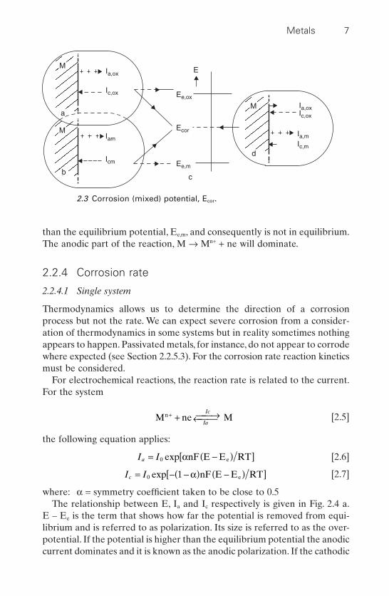
than the equilibrium potential, Ee,m, and consequently is not in equilibrium.The anodic part of the reaction, M Æ Mn+ + ne will dominate.
2.2.4 Corrosion rate
2.2.4.1 Single system
Thermodynamics allows us to determine the direction of a corrosionprocess but not the rate. We can expect severe corrosion from a consider-ation of thermodynamics in some systems but in reality sometimes nothingappears to happen. Passivated metals, for instance, do not appear to corrodewhere expected (see Section 2.2.5.3). For the corrosion rate reaction kineticsmust be considered.
For electrochemical reactions, the reaction rate is related to the current.For the system
[2.5]
the following equation applies:
[2.6]
[2.7]
where: a = symmetry coefficient taken to be close to 0.5The relationship between E, Ia and Ic respectively is given in Fig. 2.4 a.
E – Ee is the term that shows how far the potential is removed from equi-librium and is referred to as polarization. Its size is referred to as the over-potential. If the potential is higher than the equilibrium potential the anodiccurrent dominates and it is known as the anodic polarization. If the cathodic
I Ic = - -( ) -( )[ ]0 1exp a nF E E RTe
I Ia = -( )[ ]0 exp anF E E RTe
M ne Mn+ + æ Ææ¨ ææIc
Ia
Metals 7
M
a
Ia,ox
Ecor
Ee,ox
Ee,m
Ic,ox
M
d
Ia,oxIc,ox
Ia,m
Ic,m
M
b
Iam
Icm
E
c
2.3 Corrosion (mixed) potential, Ecor.
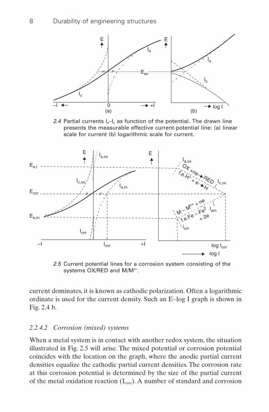
current dominates, it is known as cathodic polarization. Often a logarithmicordinate is used for the current density. Such an E–log I graph is shown inFig. 2.4 b.
2.2.4.2 Corrosion (mixed) systems
When a metal system is in contact with another redox system, the situationillustrated in Fig. 2.5 will arise. The mixed potential or corrosion potentialcoincides with the location on the graph, where the anodic partial currentdensities equalize the cathodic partial current densities. The corrosion rateat this corrosion potential is determined by the size of the partial currentof the metal oxidation reaction (Icorr). A number of standard and corrosion
8 Durability of engineering structures
E E
–I 0 +I(a) (b)
Eev
Ia
Ia
Ic
Ic
log I
2.4 Partial currents Ia–Ic as function of the potential. The drawn linepresents the measurable effective current-potential line: (a) linearscale for current (b) logarithmic scale for current.
Ee,l
E E
Ic,oxIa,m
Ia,oxOX +ne
Ic,ox
Iam
icmIcm
Icor log Icor
log I
–I +I
Ia,ox
Ecor
Ee,mM – M
n+ + ne
f.e.Fe – Fe2
+ 2e
f.e.H + + eH
RED
2.5 Current potential lines for a corrosion system consisting of thesystems OX/RED and M/Mn+.
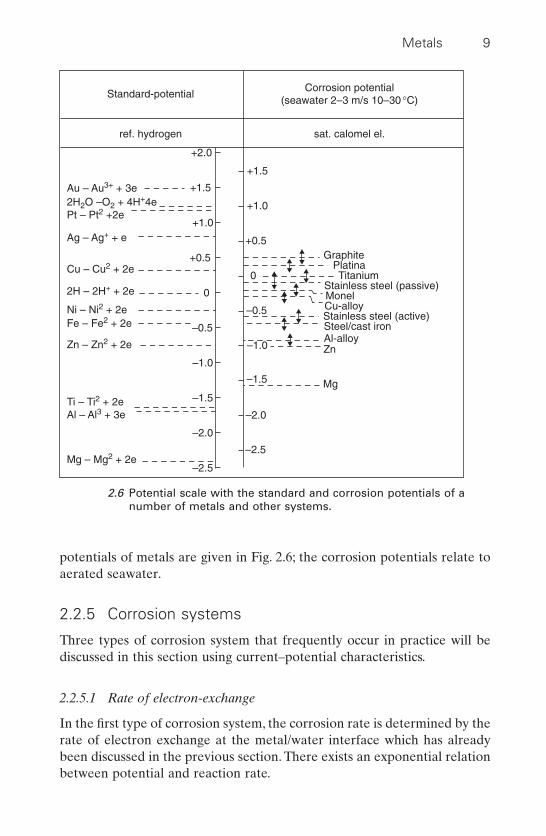
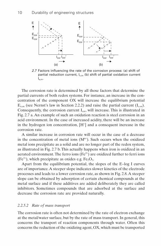
potentials of metals are given in Fig. 2.6; the corrosion potentials relate toaerated seawater.
2.2.5 Corrosion systems
Three types of corrosion system that frequently occur in practice will bediscussed in this section using current–potential characteristics.
2.2.5.1 Rate of electron-exchange
In the first type of corrosion system, the corrosion rate is determined by therate of electron exchange at the metal/water interface which has alreadybeen discussed in the previous section. There exists an exponential relationbetween potential and reaction rate.
Metals 9
Standard-potential
ref. hydrogen
Au – Au3+ + 3e
Ag – Ag+ + e
Cu – Cu2 + 2e
2H – 2H+ + 2e
Ni – Ni2 + 2eFe – Fe2 + 2e
Zn – Zn2 + 2e
Ti – Ti2 + 2eAl – Al3 + 3e
Mg – Mg2 + 2e–2.5
–2.5
–2.0
–2.0
–1.5
–1.5
–1.0
–1.0
–0.5
–0.5
0
0
+0.5
+0.5
+1.0
+1.0
+1.5
+1.5
+2.0
2H2O –O2 + 4H+4ePt – Pt2 +2e
GraphitePlatinaTitanium
Stainless steel (passive)
Stainless steel (active)
MonelCu-alloy
Steel/cast ironAl-alloyZn
Mg
Corrosion potential(seawater 2–3 m/s 10–30 °C)
sat. calomel el.
2.6 Potential scale with the standard and corrosion potentials of anumber of metals and other systems.
The corrosion rate is determined by all those factors that determine thepartial currents of both redox systems. For instance, an increase in the con-centration of the component OX will increase the equilibrium potentialEe,ox (see Nernst’s law in Section 2.2.2) and raise the partial current (Ic,ox).Consequently, the corrosion current Icor, will increase. This is illustrated inFig. 2.7 a. An example of such an oxidation reaction is steel corrosion in anacid environment. In the case of increased acidity, there will be an increasein the hydrogen ion concentration, [H+] and a consequent increase in thecorrosion rate.
A similar increase in corrosion rate will occur in the case of a decreasein the concentration of metal ions (Mn+). Such occurs when the oxidizedmetal ions precipitate as a solid and are no longer part of the redox system,as illustrated in Fig. 2.7 b. This actually happens when iron is oxidized in anaerated environment. The ferro ions (Fe2+) are oxidized further to ferri ions(Fe3+), which precipitate as oxides e.g. Fe2O3.
Apart from the equilibrium potential, the slopes of the E–log I curvesare of importance.A steeper slope indicates slower kinetics of the electrodeprocesses and leads to a lower corrosion rate, as shown in Fig. 2.8.A steeperslope can be obtained by adsorption of certain chemical compounds at themetal surface and if these additives are added deliberately they are calledinhibitors. Sometimes compounds that are adsorbed at the surface anddecrease the corrosion rate are provided naturally.
2.2.5.2 Rate of mass transport
The corrosion rate is often not determined by the rate of electron exchangeat the metal/water surface, but by the rate of mass transport. In general, thisconcerns the transport of reaction components through water. Often thisconcerns the reduction of the oxidizing agent, OX, which must be transported
10 Durability of engineering structures
E
Ecor¢Ecor
Icor
E
Ecor
Ecor¢
(a) (b)
Icor¢ Icor Icor¢
2.7 Factors influencing the rate of the corrosion process: (a) shift ofpartial reduction current, Ic,ox (b) shift of partial oxidation currentIa,m.

through water to the metal and if electron transfer at the interface is veryfast all OX particles that arrive at the metal surface will be reduced imme-diately. The magnitude of the current density is then determined by the dif-fusion rate of OX through the boundary layer at the metal surface. Theboundary current density Ibound is independent of the potential, as is illus-trated in Fig. 2.9. The partial current–potential lines of a corrosion systemthat belongs to this type is shown in Fig. 2.10. A well-known example is thecorrosion of steel in aerated, neutral water (pH ª 7), in which the oxygendissolved in the water acts as OX. In many cases in practice, precipitationof salts, lime or fouling of marine life on the steel surface can also inhibitOX transport to the metal surface and thus have a similar effect.
Metals 11
E
Ecor¢Ecor
Icor
(a)
Icor¢log I
E
Ecor¢
Ecor
Icor
(b)
Icor¢log I
E
Ecor¢Ecor
Icor
(c)
Icor¢log I
2.8 Change in slope polarization curves: (a) change in angle reductionprocess (b) change in angle oxidation process (c) both.
E
Electron transfer OX RED rate restricting
Transfer zone
Mass transport OX rate restricting
log I
Boundarycurrent
Ibound
2.9 Reduction process where mass transport restricts the rate.
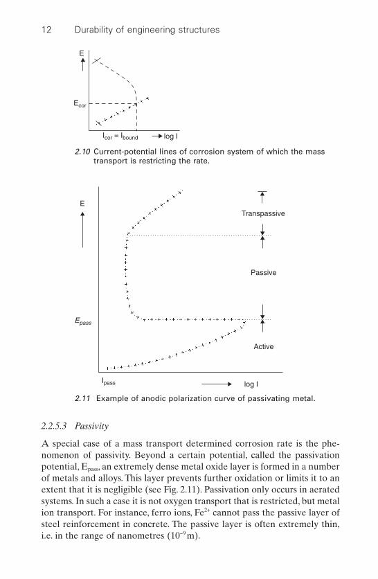
2.2.5.3 Passivity
A special case of a mass transport determined corrosion rate is the phe-nomenon of passivity. Beyond a certain potential, called the passivationpotential, Epass, an extremely dense metal oxide layer is formed in a numberof metals and alloys. This layer prevents further oxidation or limits it to anextent that it is negligible (see Fig. 2.11). Passivation only occurs in aeratedsystems. In such a case it is not oxygen transport that is restricted, but metalion transport. For instance, ferro ions, Fe2+ cannot pass the passive layer ofsteel reinforcement in concrete. The passive layer is often extremely thin,i.e. in the range of nanometres (10-9 m).
12 Durability of engineering structures
E
Ecor
Icor = Ibound log I
2.10 Current-potential lines of corrosion system of which the masstransport is restricting the rate.
ETranspassive
Epass
Ipass
Passive
Active
log I
2.11 Example of anodic polarization curve of passivating metal.
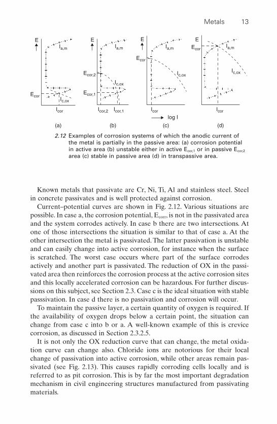
Known metals that passivate are Cr, Ni, Ti, Al and stainless steel. Steelin concrete passivates and is well protected against corrosion.
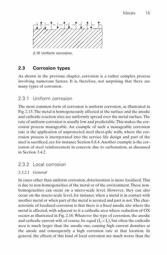
Current–potential curves are shown in Fig. 2.12. Various situations arepossible. In case a, the corrosion potential, Ecorr, is not in the passivated areaand the system corrodes actively. In case b there are two intersections. Atone of those intersections the situation is similar to that of case a. At theother intersection the metal is passivated. The latter passivation is unstableand can easily change into active corrosion, for instance when the surfaceis scratched. The worst case occurs where part of the surface corrodesactively and another part is passivated. The reduction of OX in the passi-vated area then reinforces the corrosion process at the active corrosion sitesand this locally accelerated corrosion can be hazardous. For further discus-sions on this subject, see Section 2.3. Case c is the ideal situation with stablepasssivation. In case d there is no passivation and corrosion will occur.
To maintain the passive layer, a certain quantity of oxygen is required. Ifthe availability of oxygen drops below a certain point, the situation canchange from case c into b or a. A well-known example of this is crevice corrosion, as discussed in Section 2.3.2.5.
It is not only the OX reduction curve that can change, the metal oxida-tion curve can change also. Chloride ions are notorious for their localchange of passivation into active corrosion, while other areas remain pas-sivated (see Fig. 2.13). This causes rapidly corroding cells locally and isreferred to as pit corrosion. This is by far the most important degradationmechanism in civil engineering structures manufactured from passivatingmaterials.
Metals 13
EIa,m
Ic,ox
Icor
Ecor
(a)
EIa,m
Ic,ox
Icor,2 Icor,1
Ecor,1
Ecor,2
(b)
EIa,m
Ic,ox
Icor
log I
Ecor
(c)
EIa,m
Ic,ox
Icor
Ecor
(d)
2.12 Examples of corrosion systems of which the anodic current ofthe metal is partially in the passive area: (a) corrosion potentialin active area (b) unstable either in active Ecor,1 or in passive Ecor,2
area (c) stable in passive area (d) in transpassive area.

2.2.5.4 Deliberate shift in potential
In all corrosion systems, a decrease in corrosion rate can be achieved bydecreasing the potential (Fig. 2.14). At this decreased potential, the oxida-tion current, Ia,m is no longer compensated by the reduction current Ic,ox.The difference in current, Ic,p, has to be supplied to the metal externally.This method is referred to as cathodic protection, because the artificial shiftto the lower potential causes the cathodic or reduction reaction to domi-nate. Cathodic protection is extensively applied to metal structures that arenon-passivating or show unstable passivating. This will be discussed furtherin Section 2.5.5. From the foregoing it appears that the corrosion processnot only depends on the metal, but also on the environment. Both have tobe taken into account when considering the necessity of maintenance andpreventive measures.
14 Durability of engineering structures
E
Ep
a
b
log I
2.13 Polarization curve of: a passivated metal, b the same metal but inthe presence of chloride ions.
E
Ecor
Ic,ox
Ia,m
Ic,pE¢
Icor¢ log IIcor
DE
2.14 Artificial shift from Ecor to E.
2.3 Corrosion types
As shown in the previous chapter, corrosion is a rather complex processinvolving numerous factors. It is, therefore, not surprising that there aremany types of corrosion.
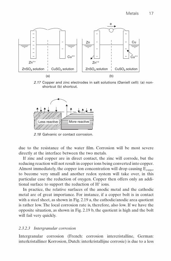
2.3.1 Uniform corrosion
The most common form of corrosion is uniform corrosion, as illustrated inFig. 2.15.The metal is homogeneously affected at the surface and the anodicand cathodic reaction sites are uniformly spread over the metal surface.Therate of uniform corrosion is usually low and predictable.This makes the cor-rosion process manageable. An example of such a manageable corrosionrate is the application of unprotected steel sheet-pile walls, where the cor-rosion process is incorporated into the service life design and part of thesteel is sacrificed, see for instance Section 6.8.4.Another example is the cor-rosion of steel reinforcement in concrete due to carbonation, as discussedin Section 3.4.2.
2.3.2 Local corrosion
2.3.2.1 General
In cases other than uniform corrosion, deterioration is more localized. Thisis due to non-homogeneities of the metal or of the environment.These non-homogeneities can occur on a micro-scale level. However, they can alsooccur on the macro-scale level, for instance when a metal is in contact withanother metal or when part of the metal is aerated and part is not.The char-acteristic of localized corrosion is that there is a fixed anodic site where themetal is affected, with adjacent to it a cathodic area where reduction of OXoccurs as illustrated in Fig. 2.16. Whatever the type of corrosion, the anodicand cathodic current will, of course, be equal (Ia = Ic), but often the cathodicarea is much larger than the anodic one, causing high current densities atthe anode and consequently a high corrosion rate at that location. Ingeneral, the effects of this kind of local corrosion are much worse than the
Metals 15
2.15 Uniform corrosion.

uniform corrosion discussed in the previous section. Its intensity is difficultto predict and to control.
2.3.2.2 Galvanic corrosion
Galvanic corrosion (French: corrosion galvanique, German: galvanischeKorrosion, Dutch: galvanische of contact corrosie). When two metals are incontact with each other there will be a potential difference between them.In the case of zinc in contact with copper, the copper is the less reactivemetal. According to Table 2.1, the standard potentials are: E0,copper =+0.34V and E0,zinc = -0.76V.
These metals can be short-circuited as in the Daniell cell shown in Fig.2.17 with the copper electrode in contact with a copper sulphate solution,the zinc electrode in contact with a zinc sulphate solution and the two solu-tions in electrical contact through a semi-permeable wall. Here there willbe a current where the zinc is the anode and is oxidized, and the copperions are reduced and precipitate on the copper electrode, the cathode. Thepotential difference V is:
[2.8]
In time, the potential difference will decrease because the copper ion con-centration, Cu2+, will decrease and the zinc ion concentration Zn2+ willincrease. The corrosion current not only depends on the potential differ-ence, but also on the ohmic resistance between the electrodes. In civil engi-neering practice, metals are mostly in direct contact, as illustrated in Fig.2.18. The less noble metal will corrode. The electrical circuit goes throughthe metals and the water film at the metal surface. The current density alsodepends on the resistance of the electrical circuit, which, in turn, is mainly
V = E E E E Cu Zncopper zinc 0,copper 0,zinc- = - + -+ +RTF
RTF2 2
2 2ln ln
16 Durability of engineering structures
(a)
(b)
2.16 (a) uniform and (b) local corrosion.
due to the resistance of the water film. Corrosion will be most severedirectly at the interface between the two metals.
If zinc and copper are in direct contact, the zinc will corrode, but thereducing reaction will not result in copper ions being converted into copper.Almost immediately, the copper ion concentration will drop causing Ecopper
to become very small and another redox system will take over, in this particular case the reduction of oxygen. Copper then offers only an addi-tional surface to support the reduction of H+ ions.
In practice, the relative surfaces of the anodic metal and the cathodicmetal are of great importance. For instance, if a copper bolt is in contactwith a steel sheet, as shown in Fig. 2.19 a, the cathodic/anodic area quotientis rather low. The local corrosion rate is, therefore, also low. If we have theopposite situation, as shown in Fig. 2.19 b, the quotient is high and the boltwill fail very quickly.
2.3.2.3 Intergranular corrosion
Intergranular corrosion (French: corrosion intercristalline, German:interkristalliner Korrosion, Dutch: interkristallijne corrosie) is due to a less
Metals 17
Zn++ Zn++
ZnSO4 solution CuSO4 solution
Cu++ Cu++
(a)
Zn
e
ZnSO4 solution CuSO4 solution
Cu
(b)
2.17 Copper and zinc electrodes in salt solutions (Daniell cell): (a) non-shortcut (b) shortcut.
More reactiveLess reactive
2.18 Galvanic or contact corrosion.

favourable microstructure, as illustrated in Fig. 2.20. The anodic areas arelocated along the grain boundaries while the crystal planes are acting ascathodes. Corrosion can penetrate into the metal along the grain bound-aries and grains can lose their bonds with adjacent grains.
The anodic areas can be the result of local separations within the metal.A well-known example is the precipitation of chromium carbides at thegrain boundaries in various austenitic steels, where the alloys stay too longin the 500–800°C temperature area due to welding. Because of the phaseseparation, there are areas at the grain boundaries that lack chromium andwill no longer passivate.This phenomenon is of great importance in weldingwhere this kind of phase separation can easily occur.
Many aluminium alloys are susceptible to intergranular corrosion as well.The heating regime during manufacturing is also of great importance withrespect to this type of corrosion.
2.3.2.4 Pit corrosion
Pit corrosion (French: corrosion par piqûres, German: Lochfrass, Dutch:putcorrosie) is a type of highly localized deterioration where pits developwith a diameter that is generally small in comparison to depth (see Fig.
18 Durability of engineering structures
Steel Cu
(a) (b)
Cu
Incorrect design
Steel
2.19 Galvanic corrosion: (a) low rate (b) high rate.
2.20 Intergranular corrosion.

2.21). This phenomenon is caused by pores in the layer that protects themetal against corrosion. In general, this concerns passivation layers but pitcorrosion is also observed under cracks in coated metals. The pit is theanode, while the environment that is still protected can act as a cathodicarea. Because the pits are only present locally there exists a largecathodic/anodic surface area.This causes a high current density at the anodeand consequently fast corrosion in the pit.
Progress of the corrosion process depends on the type of protective layer.
1 Non-conductive layersAt locations where a continuous pore extends to the surface of themetal, corrosion will occur, e.g. enamel on steel or organic coatings onsteel. If this happens in a neutral or alkaline environment, rust willdevelop in the pore, which slows down the corrosion process. In acidenvironments, corrosion products are transported further away andremoved from the pore. Consequently, the corrosion process willproceed unhampered and rapid pit formation can occur.
In the Netherlands, a well-known example is pit formation under thecracked organic high solids epoxy coating on barriers along the NorthSea coast. Figure 2.22 shows cracks of such a coating on the steel barrierdoors of the Eastern Scheldt barrier. The cracks bridge the full depth ofthe coating and beneath the crack the steel shows pit corrosion. In achloride-rich environment, corrosion products are the result of the com-plexing character of the chlorides transported easily outside of the porewhich therefore do not hamper the corrosion process. See Section 2.5.3for further details of organic protection systems.
Metals 19
2.21 Pit corrosion.

2 Metallic layersThere are two types of metallic layer:• The protection layer metal is less noble than the substrate metal, e.g.
zinc on steel. In such cases, pores or other defects do not cause pitcorrosion. At the location of the defect, zinc offers cathodic protec-tion to the steel as long as electrical conductance over the defect iswarranted.
• The protection metal is more noble than the substrate metal, e.g. tin(stannum) on steel. In the case of defects, the defect will act as ananode and the surrounding less reactive protection layer as acathode. Fast pit corrosion occurs.
3 Passive metal oxide layersMetals that owe their corrosion resistance to a passive oxide layer, suchas stainless steel and aluminium and steel in concrete, can be subject topit corrosion when in contact with water containing chloride.This threatexists for structures in marine environments and in colder climates inthe case of contact with de-icing salts. The process starts with needle-type holes that deepen and widen rapidly. At the surface, the pit is oftencovered with a porous metal oxide layer. In the case of steel, this is rust.There is no generally accepted model for the initiation of defects in thepassive layer. One of the models available shows that chloride ions areadsorbed at locations with imperfections. Anodic reactions can thentake place at the ‘poisoned’ locations. Reactions such as:
[2.9]
and
[2.10]M H O Cl MOHCL H 3e2+ + Æ + +- + +
M MOH MOH H 2e+ Æ + ++ +
20 Durability of engineering structures
2.22 Cracks in high solids epoxy coating of Eastern Scheldt barrier inthe Netherlands beneath which pit corrosion is present.

will occur at the pit, which in turn leads to local acidification and attractschloride ions from the environment so as to maintain electrical neu-trality. This will hamper repassivation of the area. In most cases, thepassive metal oxide layer is conductive, thus allowing for a cathodicreaction around the pit, e.g. oxygen reduction. Since the cathodic areais generally huge in comparison to the anodic area, the current densityin the pit can be very high. This happens, for instance, when chloridesattack stainless steel or steel in concrete.
In pure aluminium, the passive aluminium oxide layer is not conduc-tive, so the reduction reaction at the surface proceeds very slowly. Pitformation of pure aluminium in contact with chloride advances slowly.Less pure aluminium often reacts differently and conduction can bemuch better! In some products, an aluminium alloy exhibiting bettermechanical properties than pure aluminium is clad with pure aluminiumto enhance corrosion resistance.
Pit corrosion in passivated metals can also be caused by the presence ofinclusions, such as sulphides in stainless steels or precipitation of less reac-tive metal particles at the surface (for instance, copper particles on alu-minium, as shown in Fig. 2.23).
2.3.2.5 Crevice corrosion
A mechanism similar to pit corrosion occurs in crevice corrosion (French:corrosion dans les crevasses, German: Spaltkorrosion, Dutch: spleetcor-
Metals 21
2H2O + O2 + 4e 4OH–
Cu2 + 2e Cui
i
i
Al2O3
Copper particle
Hads
Habs
H+
Cl–
HClAlCl3
Al3
DE
H2Environment
H2O
Na+,Cu2+,O2
Cl–
2H+ + 2e H2
H+ + e Hads Habs
Al3+ + 2H2O = Al (OH)2+ + H+
Al Al3+ + 3e
Acidfication !
pH = 3
Al2O3Al (OH)
2.23 Pit corrosion of aluminium due to copper particles.
rosie). As the name suggests, corrosion takes place in crevices, for instancebetween bolts and nuts, between O-rings and their surroundings andbetween masonry and stainless steel lintels. In crevices where the oxygenconcentration drops to a very low level, the oxidation current density andthe reduction lines generally no longer intersect in the passivation area (Fig.2.12). The area in the crevice acts as an anode. Outside the crevice, passi-vation is intact and this area functions as a cathode. As in the case of pitcorrosion, the environment within the crevice will gradually become moreacidic and develop a higher chloride concentration. Crevice attack can alsooccur below deposits of dirt and salts and is then referred to as depositattack.
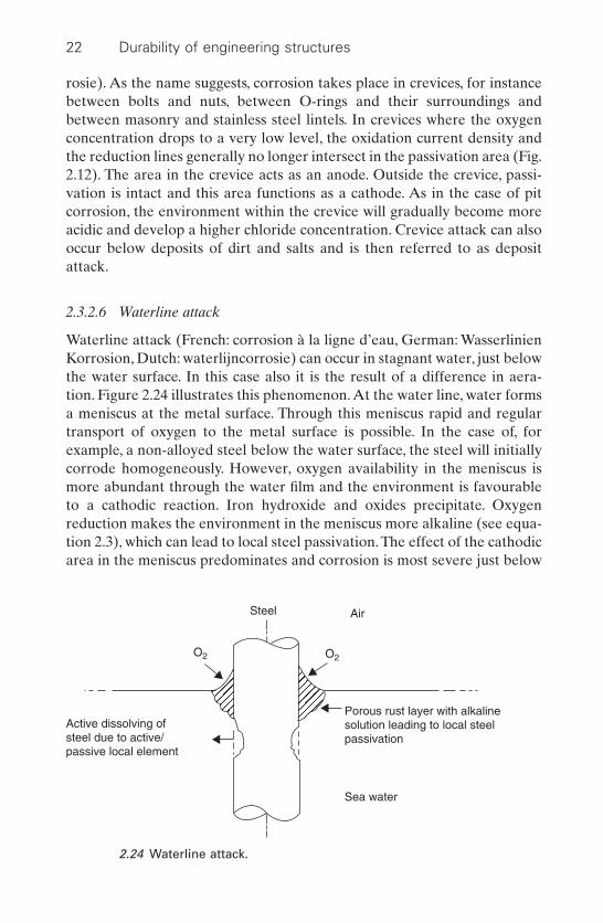
2.3.2.6 Waterline attack
Waterline attack (French: corrosion à la ligne d’eau, German: WasserlinienKorrosion, Dutch: waterlijncorrosie) can occur in stagnant water, just belowthe water surface. In this case also it is the result of a difference in aera-tion. Figure 2.24 illustrates this phenomenon.At the water line, water formsa meniscus at the metal surface. Through this meniscus rapid and regulartransport of oxygen to the metal surface is possible. In the case of, forexample, a non-alloyed steel below the water surface, the steel will initiallycorrode homogeneously. However, oxygen availability in the meniscus ismore abundant through the water film and the environment is favourableto a cathodic reaction. Iron hydroxide and oxides precipitate. Oxygenreduction makes the environment in the meniscus more alkaline (see equa-tion 2.3), which can lead to local steel passivation.The effect of the cathodicarea in the meniscus predominates and corrosion is most severe just below
22 Durability of engineering structures
Steel Air
Porous rust layer with alkalinesolution leading to local steelpassivation
O2 O2
Sea water
Active dissolving ofsteel due to active/passive local element
2.24 Waterline attack.
the water line. Due to the ohmic resistance of the electrolyte, the corrosionrate decreases the greater the distance from the surface. Gradually, the cor-rosion rate diminishes to a level determined by mass transport of oxygen,Ibound (see Section 2.2.5.2).
2.3.2.7 Filiform corrosion
Filiform corrosion (French: corrosion filiforme, German: Filgrankorrosion-fadenformige Korrosion, Dutch: draadvormige corrosie) can occur oncoated steel and aluminium. It has no bearing on the structural safety ofbuildings and is mainly a problem of appearance.
2.3.2.8 Erosion corrosion
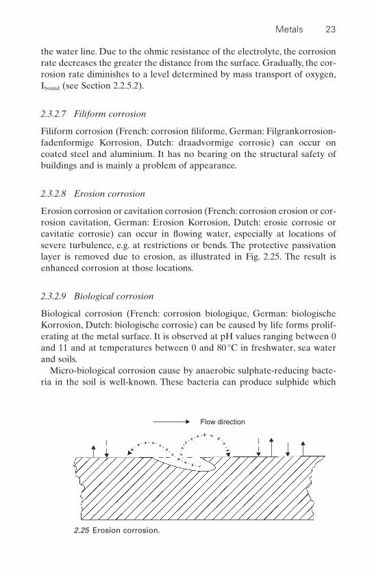
Erosion corrosion or cavitation corrosion (French: corrosion erosion or cor-rosion cavitation, German: Erosion Korrosion, Dutch: erosie corrosie orcavitatie corrosie) can occur in flowing water, especially at locations ofsevere turbulence, e.g. at restrictions or bends. The protective passivationlayer is removed due to erosion, as illustrated in Fig. 2.25. The result isenhanced corrosion at those locations.
2.3.2.9 Biological corrosion
Biological corrosion (French: corrosion biologique, German: biologischeKorrosion, Dutch: biologische corrosie) can be caused by life forms prolif-erating at the metal surface. It is observed at pH values ranging between 0and 11 and at temperatures between 0 and 80°C in freshwater, sea waterand soils.
Micro-biological corrosion cause by anaerobic sulphate-reducing bacte-ria in the soil is well-known. These bacteria can produce sulphide which
Metals 23
Flow direction
2.25 Erosion corrosion.

accelerates steel corrosion. Such corrosion can also contribute to hydrogenembrittlement in prestressed steel. Bacteria that form sulphuric acid, whichalso accelerates corrosion, can oxidize sulphur compounds in aerobic envi-ronments. This phenomenon can, for instance, occur in oil pipes and sewersand can result in rapid pipe failure. Another type of biological corrosion isdue to macro-organisms living in water, such as fungi that produce acidssuch as acetic acid and increase the corrosion rate. Algae, barnacles andmussels adhere to the metal and cover the metal surface. This is calledfouling and leads to differential aeration and attacks of the crevice corro-sion type.
2.3.2.10 Stress corrosion cracking
Stress corrosion cracking (French: corrosion fissurante sous tension,German: Spannungsrisskorrosion, Dutch: scheurvormende spanningscor-rosie) can occur in almost all construction metals. In the case of specificenvironmental conditions, even relatively innocent tensile stresses (stresseslower than the limit state values) can lead to failure.
Material loss in the corrosion process is minor and cannot usually beobserved with the naked eye. Because of this, it is difficult to inspect andfailure can occur without warning. A well-known case is the failure of stain-less steel straps of hanging ceilings in swimming pools (see Section 2.4.3).Another case is the occurrence of stress corrosion cracking in prestressedor post-tensioned steel cables in prestressed concrete.A condition for stresscorrosion cracking is the presence of tensile stresses in the metal. It is notthe average tensile stress that is important, but the local tensile stress in themetal in the area where the crack is initiated or where it continues. Ingeneral, this occurs at defects, such as pits, scratches, or at an already exist-ing crack tip. Such a local stress state is characterized by means of a stressintensity factor K.
Stress distribution at a crack tip is illustrated in Fig. 2.26. A crack withdepth a proceeds due to a tensile stress with an average size S. Stress dis-tribution in the vicinity of the crack can be determined by means of stressmechanics:
[2.11]
where: p = the size of the area in direction x, which shows plastic defor-mation when exceeding the yield stress
KI = the stress intensity factor I indicates that the stress is perpen-dicular to the crack plane
In the case considered here:
s
pyx
if x p= ≥KI
2
24 Durability of engineering structures

[2.12]
where: f(a/w) = a function of a/w
If the crack proceeds, KI can exceed a critical value (KIc) beyond which thecrack opening displacement rate will increase rapidly. KIc is lowered by cor-rosion. Consequently, crack propagation will proceed at lower stresseswhere there is corrosion than in those cases where there is none.
For engineering structures attention should be paid to stress corrosioncracking of austenitic stainless steels (see Section 2.4.3) and aluminium inchloride-containing environments. For unalloyed and low-alloyed steel,stress corrosion can occur in special environments such as in the case ofcontact with nitrate fertilizers. The sensitivity for stress corrosion occurs atincreasing concentrations and temperatures.
2.3.2.11 Hydrogen embrittlement
Hydrogen embrittlement (French: fragilisation hydrogène, German:Wasserstoff Versprödung, Dutch: waterstofverbrossing) can occur if metalsare under stress and hydrogen atoms are diffused from the surface into themetal. Hydrogen can be formed by reduction of H+. The metal is weakenedby hydrogen that has penetrated which will result in brittle failure. If hydro-gen atoms are formed, they normally recombine to form hydrogen
K fI = ◊ ( )S a wpa
Metals 25
a P
w
x
s
sy
sy
2.26 Stress distribution in the vicinity of a crack tip.

molecules but this recombination is ‘poisoned’ in some environments andsulphides are notorious examples of this type of poisoning. Welding can beanother cause of hydrogen embrittlement. Hydrogen embrittlement is occa-sionally put forward as the cause of steel cable failure in structures, butthere is little proof of this. In general, high strength steels are more sensi-tive to hydrogen embrittlement than are lower strength steels.
2.3.2.12 Corrosion fatigue
Corrosion fatigue (French: fatigue sous corrosion, German: Schwing-ungskorrosion, Korrosionermüdung, Dutch: corrosie-vermoeiing) can occurwhen metals are subjected to dynamic loading. They fail at lower stressesthan when loaded statically. This decrease in loading capacity is larger in acorrosive environment. In the case of sinusoidal loading, shown in Fig. 2.27,we can find a relationship between load S (Smax or Sa) and the number ofload cycles N, as shown in Fig. 2.28. The load-bearing capacity stabilizes insteel beyond a certain number of cycles. There is no such boundary limitfor aluminium. The effect of a corrosive environment is illustrated in Fig.2.29. In such a corrosive environment, load cycle frequency appears to beimportant, as shown in Fig. 2.30.
In practice, structures showing corrosion fatigue are designed accordingto the fail-safe principle. It is thus assumed that metal construction parts always have defects, such as inclusions, hair cracks due to welding andcorrosion pits, where fatigue cracks will initiate. Service life is then deter-mined by measuring the progress of crack propagation under practical conditions.
26 Durability of engineering structures
S
Smax
Sa
Smin
Time
One load cycle
2.27 Sinusoidal dynamic loading pattern.

Corrosion fatigue of metals can occur in a low corrosive medium, e.g.water, provided the stress level is substantial. Steel bridge decks are vul-nerable to corrosion fatigue cracking. The frequency and the amplitude ofloading appear to be unfavourable and especially high axle loading shouldbe avoided. The probability of fatigue corrosion cracking can be decreasedby the following measures: applying a non-corroding steel, e.g. a stainlesssteel, reduction of the amplitude of the dynamic loading, e.g. by increasingthe stiffness, avoiding crevices where corrosive compounds can accumulate,
Metals 27
Steel
Aluminium alloy
S
N
103 104 105 106 107 108 109 1010
2.28 Load-cycle number (S–N) curve for steel and aluminium alloy inair.
Steel
Increasing corrosive environment
S
N103 104 105 106 107 108 109
2.29 Effect of a corrosive environment on the S–N curve.

passive protection with an organic coating or active protection with metal-lic coatings or cathodic protection.
2.3.2.13 Fretting corrosion2,3
Fretting corrosion (French: fretting-corrosion, German: Reibkorrosion,Dutch: fretting) can aggravate fatigue corrosion cracking substantially. It isdue to moving surfaces of metals in contact with each other. Critical move-ments are in the range of 0.1–300 mm2. Some metal is removed from the con-tacting surface and fast corrosion occurs. Examples of cases where frettinghas occurred are in prestressed cables and tendons. Also the anchoring ofpost-tensioned steel is known to be vulnerable to fretting. Measures toprevent fretting include the use of lubricants, coating with aluminium orzinc or full protection of the steel against a corrosive environment.
2.4 Metal corrosion in practice
2.4.1 Structural steel
Steel is iron with an approximate carbon content of less than 2% and lowerpercentages of silicon. Cast iron has a higher carbon content. Structuralsteel contains less than 0.25% of carbon.
28 Durability of engineering structures
Steel in seawater
Influence of decreasingfrequency of loading
N
S
2.30 Effect frequency in dynamic loading on the S–N curve in acorrosive environment.
2.4.1.1 Atmospheric corrosion
Structural steel corrodes when exposed to air. At the cathode, hydrogen isformed. In general, reduction of H+ ions dominates in atmospheric corro-sion because the atmosphere is slightly acidic and there is an adequatewater film present at the metal surface to maintain an electrochemicalcurrent. The time of exposure to wetness of the steel surface is of particu-lar interest with respect to corrosivity of the atmospheric environment. Cli-mates are occasionally so dry that this film is absent and corrosion of baresteel and cast iron is negligible.A well-known example is the cast iron statuein New Delhi, India that has stood for over a hundred years. However, dueto air pollution, the corrosion rate has increased steeply over the past fewdecades.
Salt and dust particles can promote condensation of moisture. If precip-itated on metal surfaces, salt and dirt particles can locally increase the mois-ture conditions at the surface and decrease the electrical resistance of thewater film. Consequently, the corrosion rate will increase. For instance, SO2
is oxidized into sulphate and the iron sulphate solution is highly conduc-tive. Another negative effect of these contaminants can be a change in rustlayer morphology. SO2 and the chloride content in the air largely determinecorrosivity of the environment and its effect on structural steel. The SO2
concentration in Western countries increased steadily during most of thetwentieth century, but has fallen since the 1980s due to tough emission limitsimposed on industry. Due to the concurrent decrease of dust particles inthe air, the corrosivity of the atmospheric environment has decreased overthe past twenty years. Chloride in the air is bound to aerosol particles andis restricted to maritime areas; it decreases substantially within the first 10kilometres from the coast.
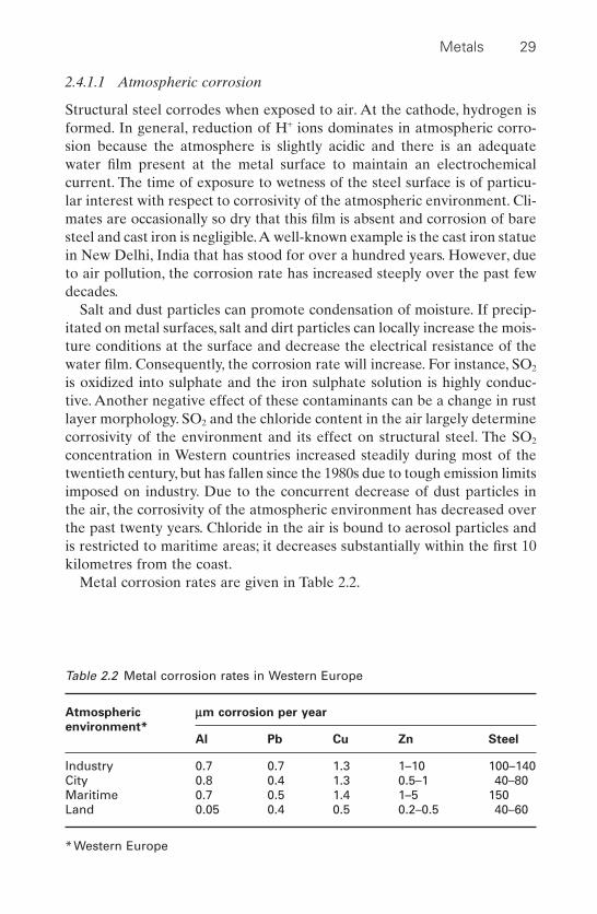
Metal corrosion rates are given in Table 2.2.
Metals 29
Table 2.2 Metal corrosion rates in Western Europe
Atmospheric mm corrosion per year
environment*Al Pb Cu Zn Steel
Industry 0.7 0.7 1.3 1–10 100–140City 0.8 0.4 1.3 0.5–1 40–80Maritime 0.7 0.5 1.4 1–5 150Land 0.05 0.4 0.5 0.2–0.5 40–60
*Western Europe

2.4.1.2 Corrosion of structural steel in water
The corrosion rate of steel (French: acier, German: Stahl, Dutch: staal) inneutral water (drinking water, seawater, most surface water) is determinedby the cathodic reaction rate:
[2.13]
The rate of this reaction depends on the time required for the water-basedoxygen gas to reach the metal surface. This process is determined by thediffusion rate and can be calculated by means of the first Fick’s law:
[2.14]
where: Dd = decrease in metal thickness in mm per yearCO2
= concentration of oxygen dissolved in mg/l waterd = thickness of the water layer over which the transport has to
proceed by diffusion
2.4.1.3 Underground corrosion
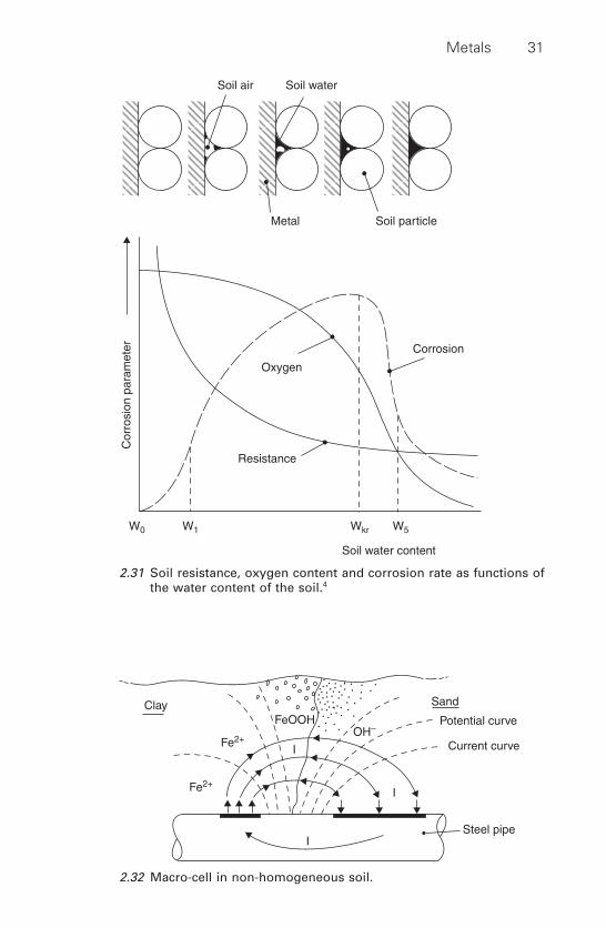
Underground corrosion processes are similar to those occurring in theatmosphere or in water. The actual rate of corrosion depends strongly onthe water content and on the salts dissolved in the water. In Fig. 2.31 typicalcorrosion parameters are shown as functions of the water content of thesoil.4 In water-saturated soil and in dry soil the corrosion can be neglected.Between these two extremes corrosive situations can arise. In sandy soilsair is usually sufficiently available to maintain the corrosion process andoften a kind of pit corrosion is observed. Clay soils often have high watercontent and contain less air and so corrosion is restricted. Dissolved saltsincrease the conductivity of the soil and increase the corrosion rate. Theelectric conductivity is considered an important criterion for the corrosiv-ity of soils.
In the case of steel going through different types of soil or in the samesoil but with layers of different levels of consolidation a macro cell can beformed with fast corrosion at the anode. Figure 2.32 shows a steel pipepassing through a sand and clay layer.5 The steel in the well-aerated sandis acting as the cathode, while the part in the clay acts as the anode. In non-aerated soils sometimes hydrogen sulphide, (H2S), is present which incontact with steel is highly corrosive.
2.4.2 Corrosion of cast iron
Cast iron (French: fonte, German: Gusseisen, Dutch: gietijzer) can be castinto intricate shapes because of its excellent fluidity at relatively low
DdCo= 14 3 2.d
O 2H O 4e OH2 2+ + -∫ 4
30 Durability of engineering structures
Metals 31
Corrosion
Oxygen
Soil water content
Resistance
W0 W1 Wkr W5
Cor
rosi
on p
aram
eter
Soil air Soil water
Metal Soil particle
2.31 Soil resistance, oxygen content and corrosion rate as functions ofthe water content of the soil.4
ClayFeOOH
Fe2+
Fe2+
I
I
I
OH–
Steel pipe
Potential curve
Current curve
Sand
2.32 Macro-cell in non-homogeneous soil.

melting point. It was used extensively for construction purposes in the nine-teenth century and the early part of the twentieth century. Today, its use instructural engineering is restricted to specific purposes. There are varioustypes of cast iron: white, grey, malleable and nodular. They all contain lessthan 3% of carbon and silicon. In general, the corrosion resistance of castiron is better than that of structural steel. With proper alloying, the resis-tance can be as good as that of stainless steel.
Cast iron shows all the types of corrosion discussed in Section 2.3. Onetype is graphite corrosion which is observed in grey cast iron. Selectiveleaching of iron takes place because graphite is cathodic to iron and so agraphite network is left, looking like a sponge under the microscope. Fre-quently, no dimensional change is observed for this type of corrosion andhence no advance warning is given, which can lead to unexpectedly hazardous situations. By alloying, cast irons can be made more corrosion-resistant. High-silicon cast irons with more than 14% of silicon show anexcellent resistance to corrosion that can even be improved in environ-ments containing chloride by further alloying with molybdenum.
2.4.3 Stainless steels
Stainless steels (French: acier inoxydable, German: Edelstahl rostfrei,Dutch: roestvast staal) are iron-based alloys containing at least 10.5% ofchromium, Cr. There are many stainless steel alloys available. For everyenvironment there are one or more stainless steel alloys that are resistant.On the other hand, not every stainless steel is resistant in any environment.The selection of a stainless steel grade for a particular application involvesconsideration of the environment in question as well as the grade’s resis-tance to that environment.
Stainless steels are categorized in five distinct families according to theircrystal structure. Within each family, there is a range of grades that variesin composition, corrosion resistance and cost. These families are: the fer-ritic, the martensic, the austenitic, the duplex and the precipitation harden-ing stainless steels. The best-known system for designating stainless steelsis that of the American Iron and Steel Institute (AISI) numbering system.Another system is the Unified Numbering System (UNS). In Europe, thedesignation according to EN 10088 is used increasingly.
Proper stainless steel grades do not corrode due to steel’s passivity underatmospheric conditions. As long as passivity is maintained, stainless steelwill perform for a very long time with minimal corrosion. However, an inad-equate grade can corrode more rapidly than plain carbon steel and will failby uniform corrosion.
In the construction industry, the austenitic grade AISI type 304 (EN1.4301) is the most commonly used but this grade is not corrosion-resistant
32 Durability of engineering structures
in a chloride environment. It shows pit corrosion and can suffer stress cor-rosion. Improved resistance against corrosion is usually obtained by alloy-ing with molybdenum, yet many of those alloys are still prone to stresscorrosion, such as the much applied AISI 316 (EN 1.4401) stainless steel,which is prone to chloride-induced stress corrosion cracking, notably in theabsence of regular cleaning, either intentionally or by rain.
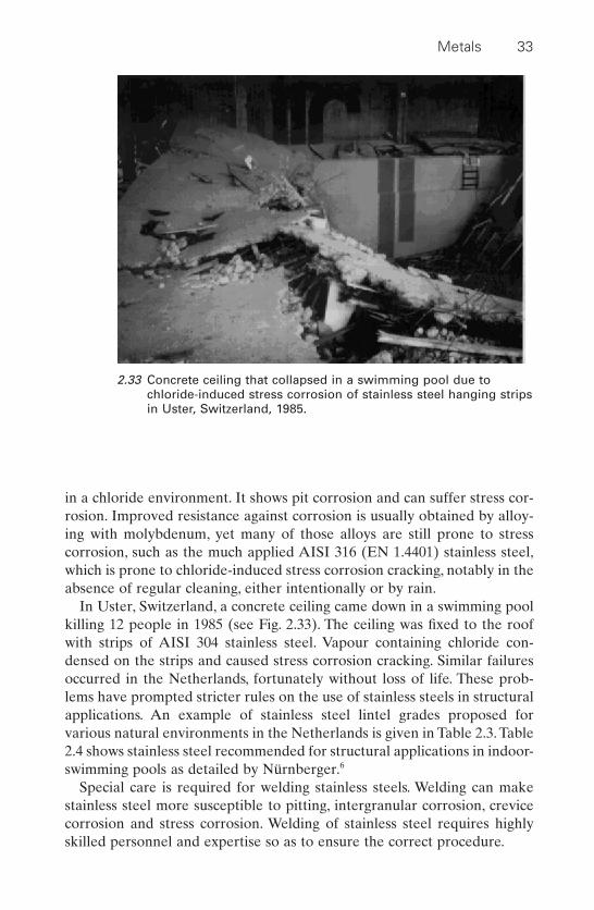
In Uster, Switzerland, a concrete ceiling came down in a swimming poolkilling 12 people in 1985 (see Fig. 2.33). The ceiling was fixed to the roofwith strips of AISI 304 stainless steel. Vapour containing chloride con-densed on the strips and caused stress corrosion cracking. Similar failuresoccurred in the Netherlands, fortunately without loss of life. These prob-lems have prompted stricter rules on the use of stainless steels in structuralapplications. An example of stainless steel lintel grades proposed forvarious natural environments in the Netherlands is given in Table 2.3. Table2.4 shows stainless steel recommended for structural applications in indoor-swimming pools as detailed by Nürnberger.6
Special care is required for welding stainless steels. Welding can makestainless steel more susceptible to pitting, intergranular corrosion, crevicecorrosion and stress corrosion. Welding of stainless steel requires highlyskilled personnel and expertise so as to ensure the correct procedure.
Metals 33
2.33 Concrete ceiling that collapsed in a swimming pool due tochloride-induced stress corrosion of stainless steel hanging stripsin Uster, Switzerland, 1985.
2.4.4 Weathering steel7
Ordinary steel rust does not protect the steel against further corrosion andit is generally accepted that the corrosion continues. Weathering steel(French: acier patinable, German: wetterfeste Stahl, Dutch: weerbestandstaal) corrodes but the rust layer becomes a barrier restricting furtheringress of moisture and oxygen. A stable condition without any furthernoticeable corrosion can be reached within a few years. This does not applyto environments where salts can be deposited, notably in marine environ-ments or those which are in contact with de-icing salts. Nor does it apply instrongly chemically-polluted environments nor where construction partswould be continuously wet or damp.
34 Durability of engineering structures
Table 2.3 Recommended stainless steel grades for lintels directly exposed tothe exterior in the Netherlands
Environment AISI/UNS EN no EN name
<10km from AISI 317LMN 1.4439 X2CrMoCuNthe coast 25.20.5
– 1.4529 X1NiCrMoCuN25.20.7
AISI 904L 1.4539 X1NiCrMoCu25.20.5
UNS 32305 1.4462 –AISI 316La 1.4404 –AISI 316Tia 1.44571 –
>10km from AISI 316 1.4401 X5CrNiMo 17.12.2the coast
AISI 304 1.4301 X5CrNi 18.10
a provided design does not allow crevice corrosion and welding is strictlycontrolled
Table 2.4 Recommended stainless steel alloys for structural elements in anindoor swimming-pool atmosphere without regular cleaning6
Domestic water (Cl £ 250mg/l)
AISI/UNS EN no EN nameAISI 317LMN 1.4439 X2CrMoCuN 25.20.5
Chloride-enriched water (e.g. saline water)
– 1.4565 X2CrNiMnMoNbN 23.17.5.3AISI 904L 1.4529 X1NiCrMoCuN 25.20.7– 1.4547 X1CrNiCuN 20.18.7

Weathering steel gains its corrosion resistance from the alloying ele-ments, usually chromium, copper and silicon. The total content of thesealloys is between 1 and 2.5%. In general, for building construction purposestwo grades are used, S235 and S355, according to the standard EN 10155.The rusting of weathering steel, although it decreases in time, should betaken into account in structural design. Allowance for loss of thicknessshould be given, depending on the environment, from fractions of milli-metres up to two millimetres.
With respect to connections with bolts and nuts large crevices should beavoided. Bolts should be of a similar weathering steel alloy. Ordinary highstrength bolts should not be used. Zinc plating is sacrificial to weatheringsteel and would result in rapid severe corrosion. Direct contacts with othermetals should be avoided because of galvanic corrosion. The fatiguestrength of weathering steel is similar to that for steel. Weathering steelshows some rusting and the rust can stain adjacent materials when rust-laden water runs off. Some materials are prone to severe staining and aredifficult or impossible to clean: concrete and stucco, galvanized steel,unglazed brick, stone and wood.
2.4.5 Aluminium
Pure aluminium has very good corrosion resistance due to the protectivepassive layer and, in general, aluminium alloys are much less corrosionresistant. The environment, alloy composition, temperature treatment andthe presence of contaminants are major factors influencing the deteriora-tion rate. The effect of the environment on the corrosion rate is given inTable 2.2.The combination of high SO2 concentration and dust can be espe-cially detrimental. Surface pollution causes higher moisture contents, betterconductivity, and local differences in aeration.Along the coast, the presenceof chloride also increases the corrosion rate.
Casting alloys, such as AlSi and AlZn, have good to moderate corrosionresistance. The wrought alloys from the 2000 and 7000 series (AlCu andAlZnMg, respectively), that are more important to the building industry,have poor to moderate resistance. Resistance can, however, be improvedeffectively by solution heat treatment, although this does affect strength.Aluminium alloys show pitting when attacked.
Aluminium, while being a more reactive metal, is sensitive to galvaniccorrosion; in particular, contact with copper must be avoided. Small copperparticles that precipitate on aluminium can cause serious trouble. Pittingcorrosion of aluminium cladding elements has been observed within 200mdistance from overhead electric railway and tramlines. Even contact withwood impregnated with copper salts must be avoided. Direct contact withsteel or iron can also enhance corrosion. In these cases, electrical insulation
Metals 35
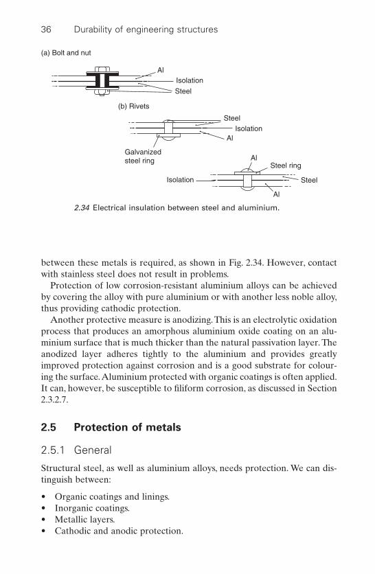
between these metals is required, as shown in Fig. 2.34. However, contactwith stainless steel does not result in problems.
Protection of low corrosion-resistant aluminium alloys can be achievedby covering the alloy with pure aluminium or with another less noble alloy,thus providing cathodic protection.
Another protective measure is anodizing.This is an electrolytic oxidationprocess that produces an amorphous aluminium oxide coating on an alu-minium surface that is much thicker than the natural passivation layer. Theanodized layer adheres tightly to the aluminium and provides greatlyimproved protection against corrosion and is a good substrate for colour-ing the surface.Aluminium protected with organic coatings is often applied.It can, however, be susceptible to filiform corrosion, as discussed in Section2.3.2.7.
2.5 Protection of metals
2.5.1 General
Structural steel, as well as aluminium alloys, needs protection. We can dis-tinguish between:
• Organic coatings and linings.• Inorganic coatings.• Metallic layers.• Cathodic and anodic protection.
36 Durability of engineering structures
(a) Bolt and nut
AlIsolation
Isolation
Isolation
(b) Rivets
Steel
Steel
Al
Al
Al
Steel
Galvanizedsteel ring
Steel ring
2.34 Electrical insulation between steel and aluminium.

2.5.2 Surface preparation
Surface preparation is a very important aspect of metal protection. Neglect-ing adequate surface preparation is penalized by early failure of the pro-tective system. Selection of the system used to protect a metal from anenvironment usually determines the requisite surface preparation.
Some systems are very sensitive to any trace of oil, fat, or remaining rust;other systems are much more tolerant. We will not discuss the sensitivity ofthe various systems.
In industrial applications complications of a fluctuating environment(weather conditions) can be avoided and in general good quality surfacepreparation is easier to achieve than is outdoor application. Good qualitysurface preparation needs skilled labour and should be carried out in accor-dance with the specifications given in such standards as ISO 12944-4, Paintand varnishes – corrosion protection of steel structures by protective paintsystems. Part 4: types of surface and surface preparation and applied strictlyaccording to the instructions given by the supplier.
A variety of surface preparation methods are available:
• Mechanical cleaning.• Solvent and chemical cleaning.• Cryogenic cleaning (not discussed here).
2.5.2.1 Mechanical cleaning
Mechanical cleaning occurs by applying a force to the surface. It can bedone by hand tool, power tool, water blasting and abrasive blasting.8
Hand tool cleaning
Hand tool cleaning is used only for removing loosely adherent paint, rust,or mill scale. Since this method is laborious, it is primarily used for spotcleaning. Hand tools include scrapers, wire brushes, abrasive pads, chisels,knives, and chipping hammers. The disadvantages of using these tools, inaddition to their slowness, are that they will not remove tightly adherentcontaminants and that they may increase burrs or dent the surface, actuallycausing some damage to the surface. In addition, these tools will not providea surface profile.
Power tool cleaning
Surface preparation using power tools is faster than hand tool cleaning; itremoves loose paint, rust, and scale, and it is good for the preparation ofwelded surfaces. Power tool cleaning is also good for removing old paint
Metals 37
that has been lifted by rust. It provides a duplication of hand tools in power-driven equipment (electric or pneumatic), such as sanders, wire brushes,grinders, clippers, needle guns, and rotary descalers. Power tools do notleave as much residue or produce as much dust as abrasive blasting does,and they are frequently used where blasting dust could damage sensitivesurroundings. However, they may polish the surface too much if used at toohigh a speed or kept in one spot for too long.
Abrasive blast cleaning
Abrasive blast cleaning is the preferred surface preparation method forpaints and coatings that require an anchor pattern and a high degree ofcleanliness. Blast cleaning is the only method that can completely removeintact mill scale and give an even roughness with a controlled anchorpattern. Abrasive blasting is the propelling, or shooting, of grit or othertypes of small, hard particles at a surface. In nozzle blasting, the force thatpropels the abrasive is compressed air. In the past, silica sand was commonlyused; however, because of the risk of silicosis, it has been banned in manycountries.
In centrifugal wheel blasting, the cleaning principle is the same. The spin-ning of large paddle wheels creates the force that throws the abrasive atthe surface. This method is usually confined to industrial use. In contrastwith open blast cleaning, the abrasives used are recyclable steel grit or shot.Vacuum blasting is another option for dust-free blast cleaning. With thistechnique, a brush surrounds the blast nozzle, and a vacuum is createdwithin the annular space. The spent abrasive and removed paint, rust, anddebris are contained by the brush, removed by the vacuum, and transportedto a separator. The debris and fine particles are removed, and the abrasiveis returned for reuse.
Water blast cleaning
Water blast cleaning (sometimes called hydro-blasting) may be high- orlow-pressure, hot or cold, and with or without a detergent, depending onthe type of cleaning desired. This process removes loose flaky rust, paint,and mill scale. It has gained wide acceptance where abrasive blast cleaning,dust, and contamination present a hazard either to personnel or to machinery.
Low-pressure washing (<14MPa or 2000psi) is effective in removing dirt,mildew, and chalk from the coating surface. Low-pressure water blast unitsuse the same components as high-pressure water blast equipment. Low-pressure cleaning is referred to as power washing and should be recognized
38 Durability of engineering structures
as such. For the cleaning of steel, water pressures as high as 69MPa (10000psi) are used.
Water alone does not etch a metal surface or remove tight paint, rust, ormill scale. Therefore, abrasives can be injected into the water stream toremove tightly adhering materials, to hasten the cleaning or to roughen thesurface profile. Any type of abrasive that is commonly used with abrasiveblast cleaning can be used in water blast cleaning. Injecting abrasives intothe water eliminates the dust that normally accompanies dry use of suchabrasives.
Flash rusting is a concern when using these methods. Flash rust is a lightrust layer that forms on steel after cleaning, particularly after water or wetabrasive blasting, or in humid marine environments.
2.5.2.2 Solvent and chemical cleaning
Solvent cleaning
Oil and grease can be removed using solvents. Many of the solvents usedare volatile, highly flammable and toxic. In general, their use is only per-mitted in an enclosed working space with natural ventilation, wheremechanical exhaust ventilation is present and if vapour concentrations arewithin legal boundaries during the entire work period. Solvent emissionsare increasingly restricted so as to protect the environment.
Chemical cleaning
In chemical cleaning, two types of agent are distinguished: those that do not affect the metal surface and those that do. In the former, use is madeof either detergents or alkaline cleaning agents for steel.
Agents that affect the surface are strong acids, such as hydro-chloric acid, sulphuric acid and phosphoric acid. This is called pickling (French: décapage, German: beizen, Dutch: beitsen). An inhibitor is usuallyadded to prevent too much removal of the metal. Agents are used toprepare the steel surface. Aluminium is chemically cleaned using alkalineagents.
Steam cleaning
High-temperature high-velocity wet steam is used in steam cleaning toremove heavy soil, oil, or grease. It does not remove rust or mill scale, nordoes it etch or roughen the surface. Commercial detergents can be addedto the steam to improve cleaning.
Metals 39
2.5.3 Organic coatings
We can distinguish three types of organic protectors of metals:
• Paints or coatings• Powder coatings• Linings (these are less relevant for civil engineering structures)
2.5.3.1 Paints or coatings
Conversion coatings
A conversion coating is often applied to enhance corrosion resistance andto improve adhesion. Conversion coatings are formed by the reaction ofchemical agents applied on the metal surface. The conversion coatingusually contains metal ions of the substrate metal. Often the conversioncoating is applied directly after cleaning the metal.
The following conversion coatings are used as a substrate for organiccoatings.
On steel• iron phosphate• zinc phosphate
On zinc• zinc phosphate• zinc chromate (not recommended due to harmful environmental
effects)On aluminium
• anodizing (see Section 2.4.5)• aluminium chromate (not recommended due to harmful environ-
mental effects)• aluminium phosphate
Organic paints or coatings
The most common method for protecting metals against corrosion consistsin applying an organic coating or paint.
Paints comprise the following constituents:
• Binders which are responsible for cohesion of the film and adhesion onthe metal surface. To ensure protection against corrosion, binder per-meability to aggressive compounds such as salts, is of primary impor-tance. Over the past decade, the binders used have changed a great dealdue to environmental and health reasons.
• Pigments fulfil various functions. In prime coatings that are in directcontact with the substrate, corrosion protective coatings are of interest.
40 Durability of engineering structures
Zinc-bearing paints containing zinc dust and ZnO2 are used extensively.The zinc protects the steel sacrificially if in electrical contact with thesteel. Zinc-rich coatings with 92–95% zinc in the dry film have much incommon with zinc layers applied by galvanizing as discussed in Section2.5.4. In top coatings, sheet-type pigments, such as glass or aluminiumflakes, can prevent penetration of aggressive compounds. Some pig-ments used in the past are now banned because of environmental andhealth reasons, for instance, pigments containing cadmium. Apart fromcorrosion protection, pigments are also used for aesthetic reasons.
• Solvents and thinners are usually constituents of the unhardened paintonly. They evaporate or react with the binder during curing. Theyprovide the required flow ability (viscosity). After applying paint on thesubstrate, solvents and thinners lose their function. Organic solvents andthinners, like turpentine, ethyl acetate and toluene cause air pollutionand, on evaporation, pose a health hazard to the workforce. Govern-ments in various countries have banned the use of these organic solvents.
Paints are often distinguished according to the manner of film formation:
• Physical film formation, with no change in the binder’s chemical composition.
• Chemical film formation where chemical reactions occur in the filmforming process.
A survey of various ways of film formation of paint binders is given in Table2.5 and examples of various paint systems used to protect metals in struc-tures are given in Table 2.6.
As a result of growing social pressure to decrease emissions of evaporatingsolvents and thinners, major developments have occurred in paint technol-ogy. These concern:
• The development of water-borne paints, i.e. water is used as the solventor medium for emulsions (see Table 2.5, ‘coagulation’).
• High built coatings; these are coating systems with a strongly reducedsolvent content.
• Powder coatings. Powder coat systems are generally applied by electro-static spraying. The powder particles are subsequently melted and thenmay undergo further reactions, depending on the type of organic com-pounds applied. Solidification and baking mentioned in Table 2.5 aretechniques that can be used for film formation of paint systems appliedas powder coatings.
These new paints systems must be investigated thoroughly prior to appli-cation in practice as must all new developments. High built epoxy coatings
Metals 41
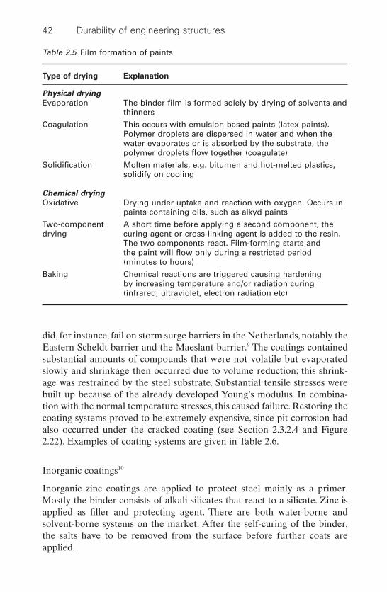
did, for instance, fail on storm surge barriers in the Netherlands, notably theEastern Scheldt barrier and the Maeslant barrier.9 The coatings containedsubstantial amounts of compounds that were not volatile but evaporatedslowly and shrinkage then occurred due to volume reduction; this shrink-age was restrained by the steel substrate. Substantial tensile stresses werebuilt up because of the already developed Young’s modulus. In combina-tion with the normal temperature stresses, this caused failure. Restoring thecoating systems proved to be extremely expensive, since pit corrosion hadalso occurred under the cracked coating (see Section 2.3.2.4 and Figure2.22). Examples of coating systems are given in Table 2.6.
Inorganic coatings10
Inorganic zinc coatings are applied to protect steel mainly as a primer.Mostly the binder consists of alkali silicates that react to a silicate. Zinc isapplied as filler and protecting agent. There are both water-borne andsolvent-borne systems on the market. After the self-curing of the binder,the salts have to be removed from the surface before further coats areapplied.
42 Durability of engineering structures
Table 2.5 Film formation of paints
Type of drying Explanation
Physical drying
Evaporation The binder film is formed solely by drying of solvents andthinners
Coagulation This occurs with emulsion-based paints (latex paints). Polymer droplets are dispersed in water and when the water evaporates or is absorbed by the substrate, the polymer droplets flow together (coagulate)
Solidification Molten materials, e.g. bitumen and hot-melted plastics, solidify on cooling
Chemical drying
Oxidative Drying under uptake and reaction with oxygen. Occurs in paints containing oils, such as alkyd paints
Two-component A short time before applying a second component, the drying curing agent or cross-linking agent is added to the resin.
The two components react. Film-forming starts and the paint will flow only during a restricted period (minutes to hours)
Baking Chemical reactions are triggered causing hardening by increasing temperature and/or radiation curing (infrared, ultraviolet, electron radiation etc)
2.5.3.2 Paint coats
The probability of defects or holidays can be much reduced by applyingmore coats, as illustrated in Fig. 2.35. The tendency in the past decades todecrease the number of coats is not a fortunate one!
2.5.3.3 Coating failure
Potential causes of coating systems failure are:• Insufficient cleaning of the metal surface. In the case of salt residue, such
features as corrosion pits that stay behind will act as corrosion centresunder the paint system applied. In general, coating systems are notimpermeable to water and oxygen, which means that corrosion canoccur in the case of corrosive materials present at the metal surface.Theuse of conversion coats or zinc-pigmented primers will decrease the vulnerability to cleaning quality.
• Coating systems can occasionally crack or delaminate, as occurred in the high built epoxy coats applied on the Dutch storm surge barriers
Metals 43
Table 2.6 Examples of protective systems on metal structures
Application/environment Coating system
Aluminium cladding Degreasing by solvent cleaning, phosphatingelements (conversion layer) one or two layers powder coat
(TGIC, epoxy)
Senzimir zinc-coated Degreasing by solvent cleaning, epoxy-polyamide steel cladding elements base layer, top layer of alkyd-melamine or acrylic
coating, alternatively PVDF top layer
Steel pylon Hot dipped zinc-coating, phosphating in case of chlorinated rubber paint and an alkyd-polyurethane coat in the case of in-factory production
Transformer boxes Abrasive blast clean, zinc-spraying, two layer of in situ protection two components epoxy coat, top layer of
polyurethane for durable gloss
Steel structures Abrasive blast cleaning, epoxy zinc coat, epoxy top layerAlternatively, high built epoxy coatings or polyurethane coating can be applied containing less solvent (see comments in previous paragraph)
Steel structures in water Abrasive blast cleaning, zinc-silicate or epoxy-zinc works coat
Underground steel Abrasive blast cleaning, epoxy-zinc coat. Epoxy containers and ducts high built top coat, cathodic protection system with
monitoring facilities to detect corrosion

discussed above. This is a basic failure of the system applied, while theprevious case is due to inadequate quality of the system’s application.
• Defects or holidays in the coating. The probability of continuous defects, as discussed in the previous section, can best be avoided byapplying the coating system in at least three coats. If a defect is present,it is the nucleus for corrosion. Due to the underrust mechanism, this willnot be restricted to the area of the defect, but expand over the surface.Along the circumference of the defect just under the coating, anodeswill form while the ‘open’ defect area will act as the cathode (see Fig.2.36).
44 Durability of engineering structures
Top coat
Middle coat
Basic layer
Steel
2.35 The effect of the number of coats on the probability of a defectpassing the whole coating system.
Paint
Steel
Anode
2H+ + 1/2O2 + 2e H2O (Cathode)
Rust
Fe Fe++ + 2e
Fe2+ + 2HO– Fe (OH)2
2H2O 2H+ + OH–
2.36 Underrust at the holiday in an organic steel coating.

2.5.3.4 Standards
ISO Standard 12944 Parts 1–8 Paints and varnishes – Protection of steelstructures against corrosion by means of paint systems is the most frequentlyused standard for the protection of steel structures. Specific protectionsystems have been standardized for specific products, such as EN 845 Specification for ancillary components for masonry.
2.5.3.5 Performance requirements
Coating systems in many countries are changing a great deal as a result ofenvironmental regulations.The old prescriptive standards and specificationsthat specify the type of coating and thickness to be applied often are notrelevant to these new systems and can lead to failure if adopted uncritically.A better approach is the specification of performance requirements. Theserequirements could, for instance, include at least five years of proven goodexperience under similar exposure conditions and resistance to acceleratednatural weathering tests. This forces manufacturers to investigate their newsystems thoroughly before putting them on the market.
In the Netherlands, the Ministry of Transport, Public Works and WaterManagement has adopted such a performance-based system for the protection of steel works. This system is discussed under Section 6.4.2.2.
2.5.4 Protection of metals by metallic coatings
2.5.4.1 Types
Protection of steel by metallic coatings is of great importance in the con-struction industry and zinc especially is important. Besides zinc, aluminiumfor spraying applications will be discussed in this chapter. Protection byother metals such as nickel, chromium, tin and lead will not be considered.
2.5.4.2 Galvanizing
Principles
Zinc is less noble than steel and will corrode prior to steel if applied as asteel coating. In such a case, zinc protects steel cathodically, as an active pro-tection (see Sections 2.2.5.4 and 2.5.5). This protection would have a shortlife if zinc could not passivate in the air but zinc forms a dense skin of zinchydroxides and carbonates (zinc-patina). Due to passivation, the corrosionrate of zinc is very low. Thus, if the zinc coat fully covers the steel surface,it will also protect in a way similar to passive organic coats. Whenever adefect occurs in the zinc layer, the area not covered with zinc will be cathod-ically protected, as illustrated in Fig. 2.37.
Metals 45

Under water, zinc is not passivated and protects only cathodically andcan thus be consumed rapidly. Zinc bars are used for cathodic protectionof steel of under-water structures, as discussed in Section 2.5.5. The corro-sion rate of zinc in the air depends on the climate. Table 2.2 shows corro-sion rates. Obviously, these are high in industrial and in marineenvironments. Industrial climates are sometimes highly polluted. Figuresgiven in Table 2.2 are for the 1970s; however, air pollution has decreasedconsiderably since then, especially in the case of SO2 emissions that areaggressive to zinc. In western countries, a marine environment is, at present,considered most aggressive to zinc. In the Netherlands, corrosion rates canbe as high as 5mm per annum along the coast. This means that, in such anenvironment, a 75mm thick zinc coat will be corroded away within 15 years.
Zinc alloys
Zinc alloys can show better corrosion resistance than does pure zinc. Exam-ples of alloys with a higher corrosion resistance are: galfan and aluzinc with3% of aluminium,and galvalume with 50% of aluminium and 1.5% of silicon.
Organic coating on zinc
Zinc can be protected by applying an organic coating (duplex system). Thisprovides an extra protection. Such a duplex system is required for a servicelife of steel parts along the coast of approximately 50 years.
Environmental pressure
The use of zinc steel has come under pressure in the Netherlands becauseof zinc leaching into the surface water. For this reason the use of zinc for
46 Durability of engineering structures
Oxygencarbonic acid
Filling up of pores and defects
Water
Protective layer ofzinc salts
Zinc (anode)
Steel (cathode)
2.37 Cathodic protection of steel by zinc coat at defect.

roofing and roof-gutters is discouraged because rainwater pollution due tozinc in solution is considered too high. Duplex systems of a zinc coat andon top of that an organic coat do not have this drawback.
Methods of galvanizing
The following methods of galvanizing are used in the protection of steel:
Hot dip galvanizing, discontinuousCleaned steel objects are completely immersed in a molten zinc bath.A relatively thick zinc coat is formed. The thickness depends on the steelthickness, but is usually thicker than 50mm. At the steel interface, aniron–zinc alloy is formed. Pure zinc is present at the surface.
Examples of hot dip galvanized steel construction products are given inTable 2.7.
Hot dip galvanizing, continuousCoils of sheet or threads are cleaned in a continuous process and trans-ported through a molten zinc bath. Because of the short period in themolten zinc bath, coat thickness is relatively thin, generally in the range of7 to 35 mm. The advantage of such a thin zinc layer is that the sheet steelcan be worked easily. The disadvantage is that corrosion resistance isreduced. The process is also referred to as Sendzimir galvanizing. The zinccoat is mostly deposited on both sides but it is also possible to galvanize onone side only.
To increase corrosion resistance, the galvanized coiled sheet is frequentlyfinished with an organic coat. Such a duplex system has a much longerservice life. One has to be aware, however, that at places where the sheetis processed further, e.g. coring a hole, the protective coat will not be presentand cathodic protection will often not suffice at these locations.
Metals 47
Table 2.7 Typical examples of hot-dip galvanized steel applications in theconstruction industry
Construction steel Cable ductsFrames Crush barriersSteel ducts Reinforcement bars (incidentally)Crash barriers Fire-escape stairsFences

ElectrogalvanizingIn electrogalvanizing a thin zinc layer is electrodeposited on the steel. Steelobjects are immersed in a water bath in which zinc salts have been dissolved. The steel objects are connected to the negative pole and the zinc anodes to the positive pole of a direct current source. The thickness ofthe zinc coat varies between 3 and 30 mm. Often corrosion resistance is improved by applying conversion layers, such as phosphates or chromates.Applications in the construction industry are for bolts and nuts, screws,sheets and pipes.
Thermal-sprayed coatings of zinc and aluminiumZinc and aluminium and their alloys are used widely for thermal sprayinganti-corrosion coats on steel structures. This technique has no limitationswith respect to the size of the structure and can be applied on site. For main-tenance of structures, the latter offers a major advantage. Zinc spraying ismore widely used, but the importance of aluminium as a spraying materialis growing due to better corrosion resistance and improved applicationtechniques. An example of a structure with a thermal sprayed aluminiumcoat is given in Fig. 2.38.
Molten zinc or aluminium is sprayed in small droplets onto the steelsurface. When the droplets land on the surface they adhere but do not flowtogether. The coat is, therefore, rather rough and porous. Thickness variesconsiderably over the surface and can be varied in a wide band betweenvarious applications, i.e. between 50 and 400 mm. Although pores in the zincor aluminium sprayed coat will be protected cathodically, it is commonpractice to apply organic topcoats or sealers to extend the service life andto improve appearance. In general, at least two coats are applied. Theprocess is used for bridges, lock doors, storm surge barriers, pipe systems,steel window frames and other items.
Other application techniques
Other less important techniques where a zinc coat is applied on construc-tion products are electrodeless zinc plating and mechanical plating.
2.5.5 Cathodic protection
2.5.5.1 Principles
In this type of protection, the potential of the metal is decreased to a levelclose to the equilibrium potential Ee,M of the metal (see Fig. 2.5).The anodicor corrosion current is then low. This method can be used if the metal to beprotected is embedded in a highly conductive environment, e.g. if it isimmersed in water or in conductive soil.
48 Durability of engineering structures

There are two types of cathodic protection:
• Sacrificial anode (French: protection cathodique par anode sacrificielle,German: kathodisches Schutz mit Opfer-anode, Dutch: kathodischebescherming met opofferanode) or passive systems where the metal isshort-circuited with a much more reactive metal.
• Impressed-current (French: protection par courant imposé, German:kathodischer Schutz mit Fremdstrom, Dutch: kathodische beschermingmet opgedrukte stroom) or active systems. The metal is connected to anexternal direct current source.
Both types are widely used.
2.5.5.2 Protection criteria
Full protection can be achieved if the metal potential is polarized to Ee,M.In practice, this is not easy to achieve, nor is it necessary. In general, polar-izing to a level half-way between the corrosion potentials Ecor and Ee,M
suffices to lower the corrosion rate to an acceptable level. In most cases, if
Metals 49
2.38 Sluice door of Zandkreeksluis in the Netherlands with thermalsprayed aluminium (courtesy: Ministry of Transport, Public Worksand Water Management, Department of Conservation, theNetherlands).
the potential of the metal is 100mV higher than Ee,M it will lower the anodiccurrent to a level below 0.1mA/m2 (about 10-4 mm metal/year). This is usedas a criterion for cathodic protection.
The protection current density depends on the corrosion system. In acidenvironments with high H+ concentrations, high current densities arerequired to achieve the required protection potential. In such cases, hydro-gen gas is developed at the metal surface with the risk of hydrogen embrit-tlement (Section 2.3.2.11). Under those circumstances, cathodic protectionmakes less sense. A much better option here is an aerated neutral or alka-line environment as, for instance, sea water, fresh-water, non-acid soils andsteel bars in concrete. In those cases, the corrosion rate is determined bythe diffusion rate of oxygen through water to the metal surface and thecurrent density necessary for protection can be low. Thus, current densitiesof 90–140mA/m2 are recommended for non-coated offshore structures inthe North Sea.
2.5.5.3 Sacrificial anodes
A metal can be used to protect another metal if, given the circumstances,it is more reactive.The standard potentials shown in Table 2.1 indicate whenthat is the case. Cathodic protection is mostly used for steel structures. Com-mercial sacrificial anodes include magnesium, zinc and aluminium alloys.These anodes can only be used in environments where no passivationoccurs, for example in sea water. Zinc bars connected to steel structuresexposed to the atmosphere make no sense!
The quantity of sacrificial anodes required depends on the protectioncurrent required, the size of the surface to be protected and the designservice life. There are various applications of cathodic protection by sacri-ficial anodes. The anodes can be placed at some distance from the object tobe protected, as illustrated in Fig. 2.39 for an underground fuel tank. Theprotection current can be measured over the connecting conducting wire.The sacrificial anode is embedded in a conductive backfill, for instance a porous cloth bag with a mixture of gypsum, bentonite clay and sodiumsulphate.
In the case of the protection of underwater pipe systems, the anodes areoften placed directly on the pipes, as shown in Fig. 2.40.
2.5.5.4 Impressed current
Figure 2.41 shows a buried pipeline cathodically protected by an impressedcurrent system. The buried anodes and the pipeline are both connected toan electrical rectifier. The rectifier supplies direct current to the pipelineand the anode. Similar systems are applied to underwater structures. Most
50 Durability of engineering structures
Metals 51
Oil tank
Zn Zn2+ + 2e
Embedding mass
2.39 Cathodic protection of a buried fuel tank using an embeddedburied zinc anode.
Anode braceletassembly
Brazed cableconnection forelectrical contact
Zn
Concrete coating
Steel pipeline
Anode segment
2.40 Zinc bracelet anode on an offshore pipeline.
V
ΩHigh
Si-diodes Choke-coil
220 V
Adjustable transformer
A
Counter electrode
Embedding massPipe
Referenceelectrode
Cu/CuSO4
2.41 Buried pipeline cathodically protected by an impressed currentsystem.
impressed current anodes are made from non-consumable electrode mate-rials, which are not easily affected by the current or the environment. Some-times scrap steel is used, such as old rails. Impressed current systems aremore complex than sacrificial anode systems. The capital expenses neces-sary to supply a direct current to the system are higher than for a simpleconnection between an anode and a cathode.
The voltage differences in sacrificial anode systems are limited to approx-imately 1V, whereas higher voltages (5–8V) are common in impressedcurrent systems.These higher voltages make it possible to protect large sur-faces with only one anode. It is also useful in low-conductivity areas, suchas in fresh water and in concrete (Section 3.9). However, there is the dis-advantage of likely over-protection. This is especially hazardous in high-strength steels and can cause hydrogen embrittlement. In the case of coatedsteel, hydrogen generation can also cause the coat to debond. The mostcommon source of electricity is a local power utility. Remote locations canuse solar cells, special fuel-driven generators and windmills. Cathodic pro-tection design is conducted by consulting companies who specialize incathodic protection systems and corrosion control.
2.5.5.5 Cathodic protection in combination with organic coatings
Cathodic protection is often applied in combination with an organic coatingsystem. An organic coat and zinc anodes protect steel ship hulls, forinstance. The cathodic protection only has to be active in areas where the
52 Durability of engineering structures
Minimal costs foroptimal protection
1000% Covered metal
Paint system
Cathodic protection
c.b. + paint
Costs
2.42 Cost optimization of a combination of cathodic protection andprotection by organic coating.

coating system protects insufficiently (defects, holidays). Pipeline systemsburied in the sea are protected by textile or glass fibre reinforced bitumi-nous or organic coats (epoxies etc.) in addition to cathodic protection.Frequently, the entire system is protected against falling stones by a layerof concrete. Attempts must be made at such a double protection system ofcost optimization. At decreasing defect rates, costs will increase, while thecosts of cathodic protection of the pipeline will decrease concurrently.Figure 2.42 shows such cost optimization. One has to be aware that the costsof pipeline failure are extremely high. An unfailing system for the expectedservice life is, therefore, a prerequisite.
An example of life cycle cost optimization for sheet-pile walls is given inSection 6.8.4.
2.6 References
1 Gellings P J, IJsseling F P, Corrosie en corrosiebestrijding. Dl. 1. Algemene inleiding (Corrosion and Corrosion Prevention, Part 1 General Introduction),Rotterdam, Nederlands Corrosie Centrum, 1988.
2 Nürnberger U, Korrosion und Korrosionschutz im Bauwesen (Corrosion andCorrosion Protection in Building), Wiesbaden, Bauverlag, Band 1 and 2 1995.
3 Waterhouse R B, Fretting Corrosion, Oxford, Pergamon Press, 1974.4 Markovic T, Bodenkorrosion und ihre Verhütung (underground corrosion and
prevention), Wiesbaden-Berlin, Bauverlag, 1963.5 Böhni H, Stalder F, ‘Korrosionsprobleme erdvergrabener Metalle (corrosion
problems in soil buried metals)’, Sweizer Ingenieur und Artchirect, 1981 33–4,703–10.
6 Nürnberger U, ‘Durability of stainless steel connections with Respect to Corrosion’, Int. Symp. Connections of Steel and Concrete, Stuttgart, RILEM Publications, 2001.
7 The Use of Weathering Steel in Bridges Brussels, ed. European convention forConstructional Steelwork ECCS CECM EKS, no 81.
8 Metals Handbook vol. 13 Corrosion, Ohio, ASM International, 1987.9 Bijen J, Montfort J, ‘Cracking of high solids epoxy coatings on steel structures
in the Netherlands’, Materials Performance, 1999 38(5) 46–51.10 Munger C G, Corrosion Prevention by Protective Coatings, Houston,TX, NACE,
1999.
Metals 53
3Concrete
3.1 Introduction
For many decades, concrete (French: béton, German: Beton, Dutch: beton)structures were regarded as virtually indestructible. Concrete was a main-tenance-free material. It was thought that the useful life of buildings wasnot determined by concrete, but by other factors. This image has changedover the last few decades. Multibillion dollar damage to bridge decks inNorth America due to corrosion caused by de-icing salts, severe wear ofconcrete structures in the Arabian Gulf Area caused by chloride-initiatedcorrosion, degradation of sewers due to sulphuric acid attack and deterio-ration caused by alkali–silica reactions in a great many countries are someof the most striking examples of concrete’s tarnished image.
Typically, where problems arise people will try to solve them. In the caseof concrete this has led to the development of measures to prevent corro-sion, corrective actions when the structural performance is affected (repairtechniques), techniques to detect corrosion and to monitor the performanceof structures.
The following subjects will be discussed in this chapter:
• Degradation mechanisms– chemical reactions in concrete;– frost/thaw (de-icing salts) damage;– corrosion of reinforcement.
• Principles of protection and repair.• Repair mortars.• Protective surface treatments.• Cathodic protection systems.• Practical cases of repair.
Much of the information provided in this chapter is taken from References1 and 2.
54

3.2 Chemical degradation mechanisms
A distinction can be made into four types of chemical reaction leading toconcrete degradation. These are:
1 Degradation of cement stone by acids (French: dégradation acide,German: Säure Angriff, Dutch: aantasting door zuren).
2 Degradation of cement stone by salts (French: dégradation saline,German: Salz Angriff, Dutch: aantasting door zouten).
3 Degradation by expansive salts (French: dégradation saline expansive,German: expansive Salz Angriff, Dutch: aantasting door expansievezouten).
4 Degradation by expansive alkali–silica reactions (French: alkali silicareaction, German: Alkali Silica Dehnung, Dutch: alkali silica reactie).
Occasionally, several of these degradation mechanisms occur simultaneously.
3.2.1 Degradation by acids
Cement stone is mainly composed of lime and silica. Since silica forms avery weak acid in water and lime is a strong base, oxides with a weaklyacidic reaction, such as carbon dioxide, can convert these cement pastes,into calcium carbonate and silica-gel. In principle, the deterioration rate isdetermined by the pH of the acid. The European Standard EN 206-1 Con-crete, Specification, Performance and Conformity presents limiting valuesfor classes of exposure to chemical attack from natural soil and groundwater. ‘Determination of the aggressiveness of water, soils and gases’ sup-plies aggressiveness criteria, as shown in Table 3.1. The most aggressiveacids are strong mineral acids, such as sulphuric acid, hydrochloric acid andnitric acid. Even if much diluted, these acids still come under class XA3:‘highly aggressive chemical environment’.
3.2.1.1 Biogenic sulphuric attack
Hydrogen sulphide forms a weak mineral acid in water. It can be found inwaste water, especially in sewer systems, but also in manure. This acid is tooweak to attack concrete severely. However, in the case of closed systems,like sewer systems, it could condense on concrete surfaces above wastewater level and subsequently oxidize biogenically to form sulphuric acid.
Sewage water systems
Various sulphur compounds are present in sewage water, both in inorganicand organic form. The most important inorganic sulphur compounds are
Concrete 55

sulphates and sulphites. Sulphates are found predominantly in domesticwaste water. Sulphites can also be present in industrial sewage water.Organic sulphur compounds are found in proteins, amino-acids and certainother compounds and can be present in domestic waste water, as well as in waste water from the food industries. Sulphate-reducing bacilli,
56 Durability of engineering structures
Table 3.1 Limiting values for classes of exposure to chemical attack fromnatural soil and ground water according to EN 206-1 Concrete, Specification,Performance and Conformity
Chemical Reference XA1d XA2d XA3d
characteristic test method
Ground water
SO42- mg/l EN 196-2 ≥200 and £600 >600 and £3000 >3000 and
£6000
pH ISO 4316 £6.5 and ≥5.5 <5.5 and ≥4.5 <4.5 and ≥4.0
CO2 mg/l prEN ≥15 and £40 >40 and £100 >100 up toaggressive 13577:1999 saturation
NH+4 mg/l ISO 7150-1 or ≥15 and £30 >30 and £60 >60 and £100
ISO 7150-2
Mg2+ mg/l ISO 7980 ≥300 and £1000 >1000 and >12000 and £3000 £24000
Soil
SO42- mg/kga EN 196-2b ≥2000 and £ >3000c and £ >12000 and
total 3000c 12000 £24000
Acidity ml/kg DIN 4030-2 >200 Not encountered in practiceBaumann Gully
a Clay soils with a permeability below 10-5 m/s may be moved to a lower class.b The test method prescribes the extraction of SO4
2- by hydrochloric acid;alternatively, water extraction can be used if experience on the in situ use ofconcrete is available.cThe 3000mg/kg limit shall be reduced to 2000mg/kg where there is a risk ofaccumulation of sulphate ions in concrete due to drying and wetting cycles orcapillary suction.d XA1 Slightly aggressive chemical environment.XA2 Moderately aggressive chemical environment.XA3 Highly aggressive chemical environment.
The aggressive chemical environments classified above are based on naturalsoil and ground water at water/soil temperatures between 5°C and 25°C anda water velocity sufficiently slow to approximate static conditions.
The most onerous value for any single chemical characteristic determines theclass.
Where two or more aggressive characteristics lead to the same class, theenvironment shall be classified into the next higher class, unless a specialstudy for this specific case proves that this is unnecessary.

Desulphovibrio desulphuricans and others reduce sulphates to sulphide.Organic sulphur compounds are also reduced to sulphides or mercaptans.These bacilli can be found in:
• Waste water.• The mud layer on the bottom of a sewage structure.• The slime layer on the wall below sewage water level.
The slime layer in particular is biogenically active. This layer can be dividedinto various zones as shown in Fig. 3.1. In the case where the oxygen contentof the sewage water is greater than 1mg/l, three layers can be distinguished.The outer layer in contact with water is aerobic.The middle and inner layersare anaerobic. Reduction of sulphur compounds can take place in themiddle layer. These sulphur compounds diffuse from the waste water intothe slime layer. When reduced, the sulphide diffuses backwards into thewaste water, but is oxidized again in the aerobic slime layer. There will,therefore, be no net reaction. However, if the waste water itself is anaero-bic, i.e. if the oxygen concentration is lower than 0.1mg/l, the aerobic slimelayer will not be present so that sulphide will enter the waste water by back-ward diffusion. Here it can form hydrogen sulphide that can escape as agas. The rate of escape is especially high in areas of turbulence.
Domestic waste water generally contains 50 to 100mg sulphate per litreand 15 to 30mg of hydrogen sulphide per litre can be formed from the sul-phate. Proteins and amino-acids can contribute another 5mg of hydrogensulphide per litre. Thus, the total hydrogen sulphide content can amount to20–35mg/litre of waste water. Above the water level, a humid atmosphere
Concrete 57
H2SAir
Waste water
[O2] < 0.1 mg/l
Sulphide present
Lam
inai
re fl
owA
naer
obe
sulp
hide
laye
rIn
ert a
naer
obe
laye
rS
lime
laye
r
Pip
e w
all
Waste water
[O2] > 1 mg/l
Aer
obe
laye
rA
naer
obe
sulp
hide
laye
rIn
ert a
naer
obe
laye
r
Pip
e w
all
Air
Oxygen penetratesinto the water
3.1 Slime layer in:(a) anaerobic sewage water(b) aerobic sewage water.
will be present, especially in the case of closed structures. Concrete walls and ceilings will be constantly wet and hydrogen sulphide gas will dis-solve in this moisture.When other sources of nourishment are present, suchas ammonia and carbon dioxide, aerobic bacilli can initiate sulphide oxida-tion. These aerobic bacilli are present because the above water level envi-ronment is often relatively oxygen-rich. Various species of bacilli are ableto convert sulphates into sulphides. As a result of this conversion, the con-crete surface environment will become more acid. When the acidity of theenvironment increases, some bacilli populations will die, but other bacilliwill encounter favourable growth conditions. The most acidic bacillus,thio-oxidans (also called Bacillus concretivorus), can exist at pH levels aslow as 1. This acidity has indeed been measured in practice. The aggres-siveness of sulphuric acid will depend on its concentration. In general, con-crete is not resistant to an acid environment with a pH lower than 4. Thismeans that it is certainly not resistant to a pH of 1 as measured in closedsewage systems. The degradation observed is therefore mainly due to thedissolving of the cement paste by a strong acid.
Rate of deterioration
At high hydrogen sulphide concentrations, the rate of degradation appearsto depend mainly on the lime content of the concrete. Pomeroy3 defines therate of deterioration of concrete by sulphuric acid as follows:
[3.1]
where:
C = Corrosion rate in mm/yearK = factor taking into account possible losses during reactionfsw = Sulphide flux to the surface of the sewer system in g/m2 hourA = the quantity of acid required to neutralize a certain amount of
concrete in comparison to a quantity of acid neutralized by the same mass of calcium carbonate
In a highly aggressive hydrogen sulphide environment, standard concretedurability parameters, such as the water/cement ratio, no longer seem toapply. However, at lower levels of aggressiveness, the familiar parametersagain seem to dominate. The transition from mildly to highly aggressivehydrogen sulphide environments is not very clear. It is, therefore, quite difficult to take the most appropriate measures for safeguarding service life design.
CK swA
=◊11 5. f
58 Durability of engineering structures

Preventive measures
In terms of volume, aggregate is the most important constituent of concrete.According to the above formula, less acid will be available for the attackon cement paste if this aggregate is able to also neutralize sulphuric acid.Therefore, in sewage systems subject to high hydrogen sulphide loading, theuse of limestone or dolomite aggregates is a measure that can decrease therate of deterioration.
At higher hydrogen sulphide levels, ordinary concrete in closed sewagestructures must be protected and one protective measure is to increase thecover. At an average degradation rate of 3mm/year, an extra cover of 60mm will be required to warrant 20 years of service without the mainstructure being affected. In large parts of the Netherlands, the soil has a lowload-bearing capacity and so an increase in concrete pipe deadweight is not regarded favourably. However, there are many alternative protectivemeasures, as discussed in Section 3.8.
Manure silos
Because of severe restrictions on the use of manure, thousands of manuresilos have been built in the Netherlands and in other European countries.There is a ban on spreading manure onto the fields during the winterbecause of percolation by rainwater and because leaching of manure canpollute the soil, especially with nitrates. Since manure also contributes toacid rain due to evaporation of ammonia, the silos have to be closed so thatammonia cannot escape into the atmosphere.
Contents of liquid manure constituents aggressive to concrete are givenin Table 3.2.4 The constituents of the manure itself are not especially aggres-sive, but as in the sewage systems, hydrogen sulphide can be formed by sulphate-reducing bacilli. An investigation into existing manure silos hasshown that in low-quality concrete a similar degradation can occur as insewage systems. In general, however, this degradation is less severe becausethe hydrogen sulphide largely escapes when manure is stirred periodically.
Concrete 59
Table 3.2 Contents of aggressive constituents in liquid manure (mg/l)4
Cattle Poultry Pig
Mg 810–1570 1260–2380 640–2000Cl 1810–4180 80–3220 640–3360N 3800–7600 5950–15750 4320–11520SO3 2000–3000 2000–4000 1000–2000
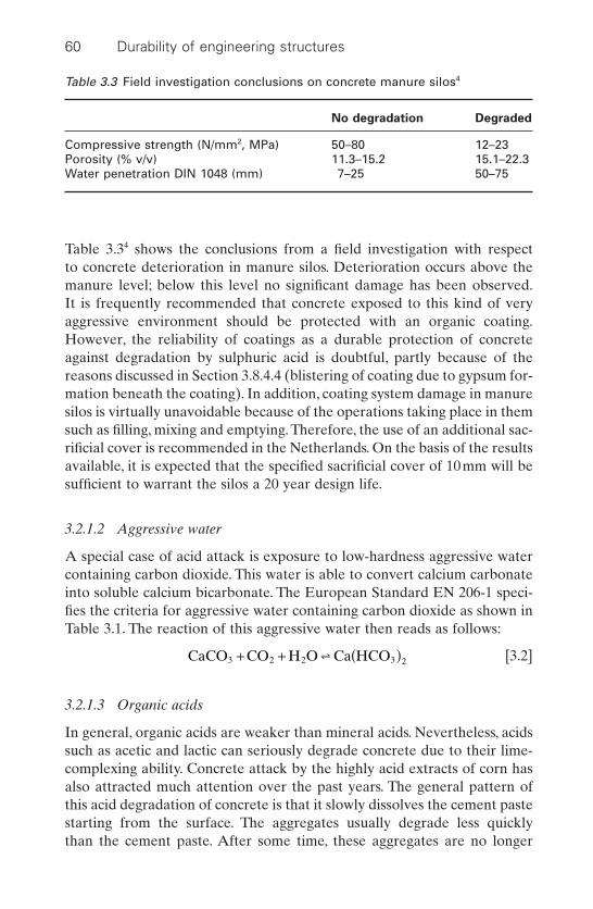
Table 3.34 shows the conclusions from a field investigation with respect to concrete deterioration in manure silos. Deterioration occurs above themanure level; below this level no significant damage has been observed.It is frequently recommended that concrete exposed to this kind of veryaggressive environment should be protected with an organic coating.However, the reliability of coatings as a durable protection of concreteagainst degradation by sulphuric acid is doubtful, partly because of thereasons discussed in Section 3.8.4.4 (blistering of coating due to gypsum for-mation beneath the coating). In addition, coating system damage in manuresilos is virtually unavoidable because of the operations taking place in themsuch as filling, mixing and emptying. Therefore, the use of an additional sac-rificial cover is recommended in the Netherlands. On the basis of the resultsavailable, it is expected that the specified sacrificial cover of 10mm will besufficient to warrant the silos a 20 year design life.
3.2.1.2 Aggressive water
A special case of acid attack is exposure to low-hardness aggressive watercontaining carbon dioxide. This water is able to convert calcium carbonateinto soluble calcium bicarbonate. The European Standard EN 206-1 speci-fies the criteria for aggressive water containing carbon dioxide as shown inTable 3.1. The reaction of this aggressive water then reads as follows:
[3.2]
3.2.1.3 Organic acids
In general, organic acids are weaker than mineral acids. Nevertheless, acidssuch as acetic and lactic can seriously degrade concrete due to their lime-complexing ability. Concrete attack by the highly acid extracts of corn hasalso attracted much attention over the past years. The general pattern ofthis acid degradation of concrete is that it slowly dissolves the cement pastestarting from the surface. The aggregates usually degrade less quickly than the cement paste. After some time, these aggregates are no longer
CaCO CO H O Ca HCO3 2 2 3 2+ + ( )∫
60 Durability of engineering structures
Table 3.3 Field investigation conclusions on concrete manure silos4
No degradation Degraded
Compressive strength (N/mm2, MPa) 50–80 12–23Porosity (% v/v) 11.3–15.2 15.1–22.3Water penetration DIN 1048 (mm) 7–25 50–75

embedded in the cement paste. Sometimes, the aggregate itself is alsodegraded. Which happens, for instance, when limestone or dolomite aggre-gates are used. In this case degradation initially looks more severe, but whendegradation proceeds, the situation reverses because lime or dolomite pro-vides an additional alkaline buffer that can neutralize the acid.
3.2.2 Degradation of cements by salts
3.2.2.1 Ammonium salts
The ammonium ion (NH +4) is quite innocent in itself. However, the cation
is always found in combination with an anion and this anion usually reactswith cement hydrates. As calcium salts are formed, the ammonium ionchanges to and is released as gaseous ammonia. The release of ammoniashifts the reaction to the right, as shown, for instance, in the reaction withammonium nitrate:
[3.3]
Both water-soluble calcium nitrate and ammonia can easily leave concrete.With respect to ammonia, EN 206 specifies the classes of aggressiveness asshown in Table 3.1. Although the table suggests that ammonium salts areaggressive even in small concentrations, some ammonium salts are less haz-ardous, e.g. ammonium carbonate, oxalates and fluoride. Even though thesesalts attack the cement paste, the reaction products are insoluble and non-expansive and therefore less aggressive than salts such as ammoniumnitrate and ammonium sulphate. Ammonium sulphate can react withcement paste to produce calcium sulphate. Subsequently, this sulphate canlead to ettringite formation.
3.2.2.2 Magnesium salts
Magnesium salts react first with calcium hydroxide, forming low solublemagnesium hydroxide. However, magnesium is also able to react withcalcium silicate hydrate gel, as shown in the following reaction:
[3.4]
Non-cementing reaction products, such as brucite, are formed in this reac-tion. However, if the magnesium salt is magnesium sulphate, an additionaldegradation factor due to sulphate deterioration can, of course, occur. EN206 specifies classes of aggressiveness as shown in Table 3.1.
3.2.2.3 Fertilizers/nutrients
Greenhouse foundations are mostly made of concrete.They consist of smallprecast concrete piles embedded in concrete poured in situ as shown in Fig.
CSHgel Mg Mg OH Ca SiO H O22
22 2+ Æ ( ) + + ++ +
CSHgel 2NH NO Ca NO 2NH SiO H O4 3 3 2 3 2 2+ Æ ( ) + ≠ + +
Concrete 61

3.2.1 A temperature of 20 to 25°C is maintained in greenhouses. Nourish-ment solutions are sprayed onto the soil continuously or at regular inter-vals and they have the composition shown in Table 3.4. They contain muchnitrate, sometimes sulphate, always some ammonium, calcium, and magne-sium as well. These nourishment solutions penetrate the soil, are absorbedby the concrete and transported through the pore system down to theground level where the water evaporates and the salts remain. Severe dete-rioration has been observed at ground level. Expansion was occasionallyobvious. The concrete always appeared to have lost its integrity, oftenwithout signs of expansion. Figure 3.3 shows a deteriorated pile.
A reaction of ammonium salts and magnesium salts with the calcium sil-icate hydrate gel of the cement paste can take place and ettringite forma-tion has also been observed.An accumulation of the most mobile ions couldbe observed above ground level, whereas the less mobile ions were concentrated below ground level. Expansion due to ettringite formation(Section 3.2.3.1) was occasionally present; in other cases ettringite could bedetected but no expansion was observed. In the latter case it was consid-ered likely that cement paste degradation occurred first, while ettringite for-mation took place later on. Ettringite formation occurred when there wasenough space to release the expansive ettringite forces. The results of theresearch into hothouse concrete foundations has been used for the formu-lation of CUR Recommendation 8 Durability of concrete foundations ingreenhouses.5 The most important requirements in this Recommendation
62 Durability of engineering structures
Deterioratedzone
Evaporation
Steel column
Plant nourish-ment solution
Mg++ SO4– –
NH4+ NO3
– K+
Ground level
Pile
Pour
± 400
± 40
0±
400
± 30
0
3.2 Greenhouse foundation showing salt transport.1
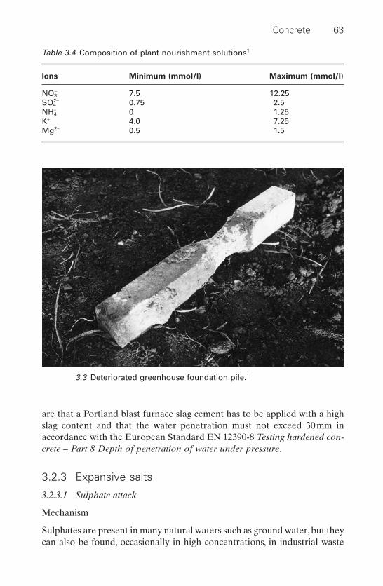
are that a Portland blast furnace slag cement has to be applied with a highslag content and that the water penetration must not exceed 30mm inaccordance with the European Standard EN 12390-8 Testing hardened con-crete – Part 8 Depth of penetration of water under pressure.
3.2.3 Expansive salts
3.2.3.1 Sulphate attack
Mechanism
Sulphates are present in many natural waters such as ground water, but theycan also be found, occasionally in high concentrations, in industrial waste
Concrete 63
Table 3.4 Composition of plant nourishment solutions1
Ions Minimum (mmol/l) Maximum (mmol/l)
NO3- 7.5 12.25
SO42- 0.75 2.5
NH+4 0 1.25
K+ 4.0 7.25Mg2+ 0.5 1.5
3.3 Deteriorated greenhouse foundation pile.1
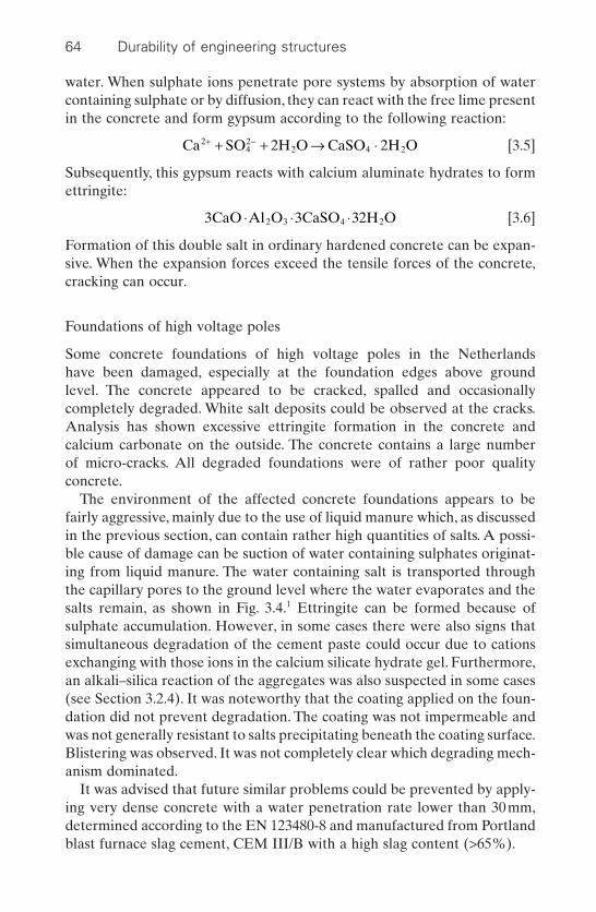
water. When sulphate ions penetrate pore systems by absorption of watercontaining sulphate or by diffusion, they can react with the free lime presentin the concrete and form gypsum according to the following reaction:
[3.5]
Subsequently, this gypsum reacts with calcium aluminate hydrates to formettringite:
[3.6]
Formation of this double salt in ordinary hardened concrete can be expan-sive. When the expansion forces exceed the tensile forces of the concrete,cracking can occur.
Foundations of high voltage poles
Some concrete foundations of high voltage poles in the Netherlands have been damaged, especially at the foundation edges above ground level. The concrete appeared to be cracked, spalled and occasionally completely degraded. White salt deposits could be observed at the cracks.Analysis has shown excessive ettringite formation in the concrete andcalcium carbonate on the outside. The concrete contains a large number of micro-cracks. All degraded foundations were of rather poor quality concrete.
The environment of the affected concrete foundations appears to befairly aggressive, mainly due to the use of liquid manure which, as discussedin the previous section, can contain rather high quantities of salts. A possi-ble cause of damage can be suction of water containing sulphates originat-ing from liquid manure. The water containing salt is transported throughthe capillary pores to the ground level where the water evaporates and thesalts remain, as shown in Fig. 3.4.1 Ettringite can be formed because of sulphate accumulation. However, in some cases there were also signs thatsimultaneous degradation of the cement paste could occur due to cationsexchanging with those ions in the calcium silicate hydrate gel. Furthermore,an alkali–silica reaction of the aggregates was also suspected in some cases(see Section 3.2.4). It was noteworthy that the coating applied on the foun-dation did not prevent degradation. The coating was not impermeable andwas not generally resistant to salts precipitating beneath the coating surface.Blistering was observed. It was not completely clear which degrading mech-anism dominated.
It was advised that future similar problems could be prevented by apply-ing very dense concrete with a water penetration rate lower than 30mm,determined according to the EN 123480-8 and manufactured from Portlandblast furnace slag cement, CEM III/B with a high slag content (>65%).
3CaO Al O 3CaSO 32H O2 3 4 2◊ ◊ ◊
Ca SO 2H O CaSO 2H O242
2 4 2+ -+ + Æ ◊
64 Durability of engineering structures

Sulphate attack in sea water
Sulphate resistance has long been advocated as an essential quality ofmarine structure durability. However, in the case of the joint presence of chlorides and sulphates, strong evidence was found that the hazards ofsulphates are negligible. Although ettringite is found, it appears not to be expansive.
3.2.3.2 Thaumasite
Another expansive sulphate double salt is thaumasite for which the formulais:
[3.7]
Formation of this salt not only requires sulphate, but also calcium carbon-ate. Calcium carbonate is not always present in concrete, but could be thereif the carbonation frontier advances (Section 3.4.2) or when using limestoneaggregates. Thaumasite formation is especially expansive at low tempera-tures. Damage that can be ascribed to thaumasite formation as a deterio-rating salt is only of recent date. During thaumasite formation, ettringiteoccurs as an intermediate salt. EN 206 specifies the classes of aggressive-ness for water containing sulphate as given in Table 3.1.
CaSiO CaSO CaCO 15H O3 4 3 2◊ ◊ ◊
Concrete 65
Rain
Evaporation
Manure
Ground level
Ground water
Porous coating
3.4 Degradation mechanism in high-voltage pole foundations.1
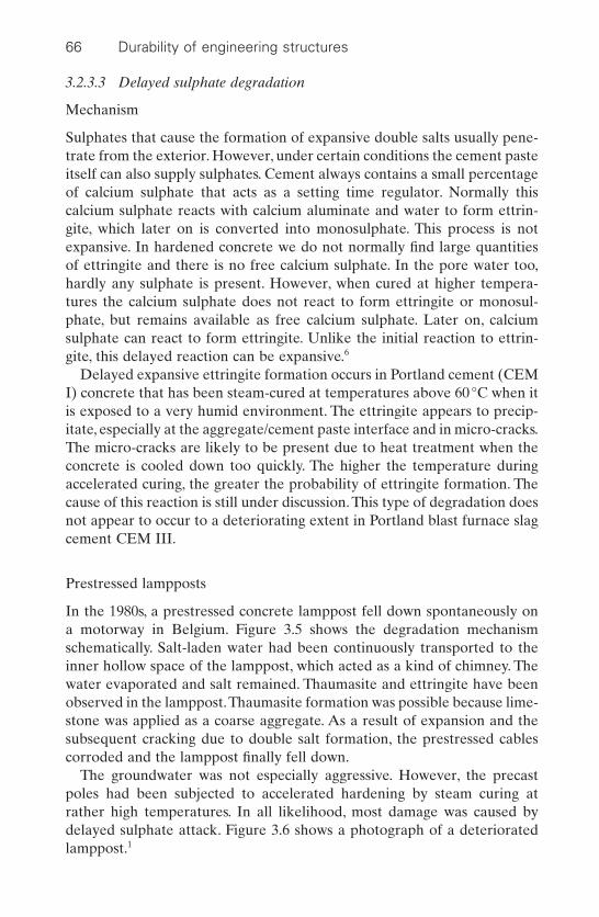
3.2.3.3 Delayed sulphate degradation
Mechanism
Sulphates that cause the formation of expansive double salts usually pene-trate from the exterior. However, under certain conditions the cement pasteitself can also supply sulphates. Cement always contains a small percentageof calcium sulphate that acts as a setting time regulator. Normally thiscalcium sulphate reacts with calcium aluminate and water to form ettrin-gite, which later on is converted into monosulphate. This process is notexpansive. In hardened concrete we do not normally find large quantitiesof ettringite and there is no free calcium sulphate. In the pore water too,hardly any sulphate is present. However, when cured at higher tempera-tures the calcium sulphate does not react to form ettringite or monosul-phate, but remains available as free calcium sulphate. Later on, calciumsulphate can react to form ettringite. Unlike the initial reaction to ettrin-gite, this delayed reaction can be expansive.6
Delayed expansive ettringite formation occurs in Portland cement (CEMI) concrete that has been steam-cured at temperatures above 60°C when itis exposed to a very humid environment. The ettringite appears to precip-itate, especially at the aggregate/cement paste interface and in micro-cracks.The micro-cracks are likely to be present due to heat treatment when theconcrete is cooled down too quickly. The higher the temperature duringaccelerated curing, the greater the probability of ettringite formation. Thecause of this reaction is still under discussion. This type of degradation doesnot appear to occur to a deteriorating extent in Portland blast furnace slagcement CEM III.
Prestressed lampposts
In the 1980s, a prestressed concrete lamppost fell down spontaneously ona motorway in Belgium. Figure 3.5 shows the degradation mechanismschematically. Salt-laden water had been continuously transported to theinner hollow space of the lamppost, which acted as a kind of chimney. Thewater evaporated and salt remained. Thaumasite and ettringite have beenobserved in the lamppost.Thaumasite formation was possible because lime-stone was applied as a coarse aggregate. As a result of expansion and thesubsequent cracking due to double salt formation, the prestressed cablescorroded and the lamppost finally fell down.
The groundwater was not especially aggressive. However, the precastpoles had been subjected to accelerated hardening by steam curing at rather high temperatures. In all likelihood, most damage was caused bydelayed sulphate attack. Figure 3.6 shows a photograph of a deterioratedlamppost.1
66 Durability of engineering structures
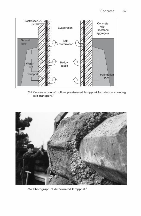
Concrete 67
Evaporation
Saltaccumulation
Hollowspace
Prestressedcable
Groundlevel
Water+ salt
Transport Foundationpour
Concretewith
limestoneaggregate
3.5 Cross-section of hollow prestressed lamppost foundation showingsalt transport.1
3.6 Photograph of deteriorated lamppost.1

3.2.3.4 Salt weathering
Another type of salt attack in concrete structures is surface salt weather-ing, also referred to as physical salt attack. In the tidal and spray zones, saltswill be deposited at the concrete structure surface during dry–wet cycles.Sea salt is deposited on the concrete and partly sucked into the concretesurface skin. Crystallization and hydration of salts cause swelling, which candisrupt the surface and lead to a washed-out surface texture, especially inthe spray-zone.A salt well known for its hydration pressure is the thenarditeform of sodium sulphate (Na2SO4), that reacts with water to form mirabil-lite (Na2SO4 · 10H2O).
[3.8]
This reaction frequently takes place where the ground water is often verysalty and the evaporation rate high, for instance in the Gulf area.
3.2.4 Alkali silica reaction
3.2.4.1 Reaction mechanism
Some aggregates appear to react expansively with cement. Beyond a certainexpansion rate, concrete cracks. This expansion is mainly caused by solublesilica minerals in the aggregates.
The following phenomena can be observed:
• Expansion of the concrete.• Small crack formation at the surface.• Spalling of concrete.• Expulsion of alkali–silica gel.
Figure 3.7 shows an example of a structure affected by an alkali–silica reaction. Two reaction mechanisms can be distinguished in thisprocess: the silica solution that reacts with alkalis and the expansionprocess. Silica dissolves because of the highly alkaline environment of the pore water in the concrete where the pH can be as high as 14. A sodium silicate and potassium silicate solution is then formed. The second part of the mechanism concerns an osmotic process. The silicatesolution tries to equalize its salt concentration with the surrounding porewater system. However, around the aggregate a semi-permeable barrier ispresent in which calcium plays a role. The silicates cannot pass this barrier,but water can so the silicate solution attracts water and, the silicate com-pound swells.
The rate of this expansive reaction depends on silica solubility.
Na SO 10H O NaSO 10H O2 4 2 4 2+ ¤ ◊
68 Durability of engineering structures
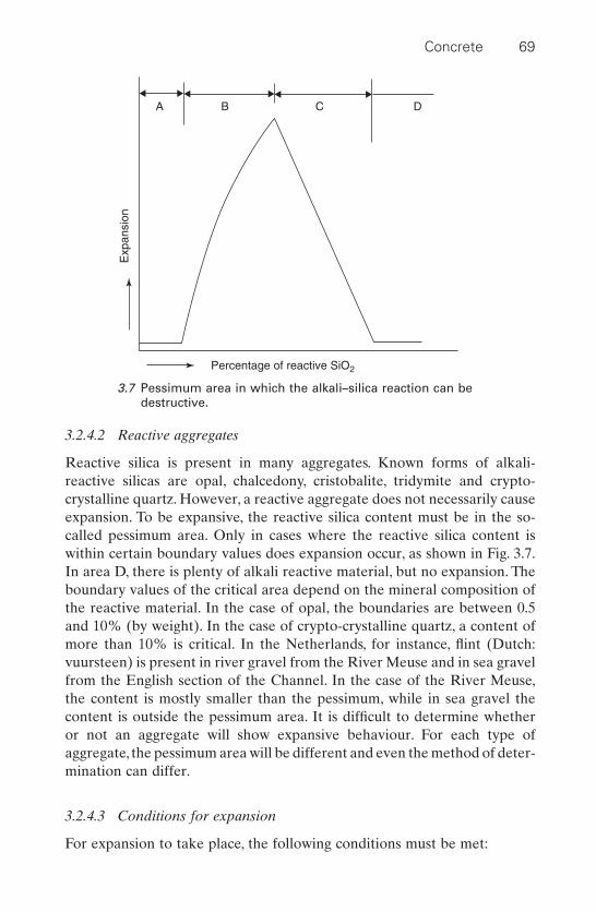
3.2.4.2 Reactive aggregates
Reactive silica is present in many aggregates. Known forms of alkali-reactive silicas are opal, chalcedony, cristobalite, tridymite and crypto-crystalline quartz. However, a reactive aggregate does not necessarily causeexpansion. To be expansive, the reactive silica content must be in the so-called pessimum area. Only in cases where the reactive silica content iswithin certain boundary values does expansion occur, as shown in Fig. 3.7.In area D, there is plenty of alkali reactive material, but no expansion. Theboundary values of the critical area depend on the mineral composition ofthe reactive material. In the case of opal, the boundaries are between 0.5and 10% (by weight). In the case of crypto-crystalline quartz, a content ofmore than 10% is critical. In the Netherlands, for instance, flint (Dutch:vuursteen) is present in river gravel from the River Meuse and in sea gravelfrom the English section of the Channel. In the case of the River Meuse,the content is mostly smaller than the pessimum, while in sea gravel thecontent is outside the pessimum area. It is difficult to determine whetheror not an aggregate will show expansive behaviour. For each type of aggregate, the pessimum area will be different and even the method of deter-mination can differ.
3.2.4.3 Conditions for expansion
For expansion to take place, the following conditions must be met:
Concrete 69
Percentage of reactive SiO2
Exp
ansi
onA B C D
3.7 Pessimum area in which the alkali–silica reaction can bedestructive.

• Presence of alkali-reactive aggregates.• Sufficient water present in concrete. Destructive expansion only occurs
in the case of continuously or intermittently wet conditions.• Sufficient alkali content in the concrete’s pore water. Alkali content is
expressed in Na2O-equivalency. It is the sum of the sodium oxide (Na2O)content plus 0.658 times the potassium oxide (K2O) content. At anNa2O-equivalency of less than 0.6%, it was shown that no alkali–silicareaction occurs in Portland cement. This will, however, be different inother cements. In blast furnace slag cements, such as CEM III/A and B, the limit can be substantially higher because the alkali percentagethat dissolves in pore water is substantially lower than in Portlandcements.
• Even when the initial alkali content is below the boundary values, thealkali content can increase due to alkali ingress from the exterior as will,for instance, be the case when de-icing salts are used.
• Ion mobility must be sufficient. A high diffusion resistance will preventor decrease the expansion rate. Blast furnace cement CEM III/A and Band Portland fly-ash cement (CEM II/B-V according to EN 197) do havea substantially lower mobility than Portland cement, CEM I.
A decrease of the water/cement ratio also increases the diffusionresistance. However, the effect of the water/cement ratio on the diffusion resistance is much less than the effect of the cement type.Moreover, at decreasing water/cement ratios, alkalinity increases, whichpromotes alkali–silica reactions.
• There must be free lime in the vicinity of the aggregates. If free lime isnot available, there is no expansion, probably because the semi-impermeable layer around the aggregate is not formed. This can beanother reason why blast furnace cement and Portland fly ash cementdo not show destructive expansion, whereas Portland cement does. Ithas been observed that the interfacial zone between the cement pasteand aggregate is substantially less thick and less free lime is present inblast furnace cement and Portland fly ash cement.
3.2.4.4 Measures to prevent ASR damage
Measures to prevent damage by alkali–silica reaction are:
• Use of non alkali-reactive aggregates.• Restricting the alkali content in concrete or cement, e.g. the use of low-
alkali Portland cements with an alkali content (Na2O equivalency) lower than 0.6%, but this does help sufficiently in the case of alkalis penetrating from the exterior.
• The use of additions as in blast furnace slag cements (CEM III) andPortland fly ash cement (CEM II/B-V) as discussed in the previous
70 Durability of engineering structures
section. In that case restrictions on the alkali content could be allevi-ated as shown in Table 3.5 which presents Dutch recommendations.7
• Restricting the access of water to the concrete: this restriction is oftentoo demanding.
3.3 Frost–thaw and de-icing salt damage
3.3.1 Frost–thaw
Frost–thaw damage (French: gel et dégel, German: Frost–Tau, Dutch:vorst–dooi) is due to expansion that occurs when water is converted intoice and to the difference in the temperature coefficients.At decreasing tem-peratures, the water present in the largest pores will start to freeze first.When water turns into ice, the expansion is 9%. If concrete is saturated withwater, this will cause forces exceeding the tensile strength. Consequently,the concrete will crack. Fortunately, concrete is seldom fully saturated andthe larger pores will be filled with water to a lesser degree, as shown in Fig. 3.8. There will, therefore, be space available for expansion and nodamage will occur. Expanding ice pushes away the surrounding water intothe smaller pores.This causes hydraulic pressure in the pore system. In somemodels, this hydraulic pressure is considered the cause of expansion, buthere we will consider a model based on the assumption that damage occursnot during freezing, but during thawing. This model is illustrated in Figs. 3.9and 3.10.
When water in the large pores freezes, water will be attracted from adja-cent smaller pores, both in fluid and in vapour form. The smaller pores are
Concrete 71
Table 3.5 Requirements to be met by cements so as to prevent ASR accordingto Dutch CUR Recommendation 897
CEM II/B-V CEM II/B-V CEM III/A CEM III/B
Cement, fly ash, slag ≥25 ≥25 ≥50 ≥66content (% by weight), resp.
Na2O-equivalency of fly 1 £ x £ 2 2 < x £ 3 – –ash (% by weight)
Maximum alkali content of cement (% by weight)• In the case of alkali 1.1 1.3 1.1 1.5
contribution, otherconstituents £0.6kg/m3
• In the case of alkali 0.9 1.1 0.9 1.3contribution, otherconstituents £1.2kg/m3
72 Durability of engineering structures
T > 0 °C.
H2O
3.8 Water in cement stone pores, temperature above freezing point.
ice
T < 0 °C
3.9 Frozen water in large pores.
more or less freeze-dried by the ice in the larger pores. Consequently, theice in the larger pores will grow. This is similar to the process of ice lensgrowth observed in soil. If temperatures subsequently rise, the ice willexpand and since the temperature expansion coefficient of ice is five timeslarger than that of concrete, it will exert a force. It can then be calculatedthat a tensile force will be introduced that can be expressed as 0.36 ¥DTN/mm2. This means that at a change in temperature of 15°C, the tensilestrength of concrete will be exceeded. (It should be stressed that the fore-going describes only one of the models that explains the frost–thaw dete-rioration of concrete.)
Because of the complexity of the frost–thaw process, it is understandablethat it is difficult to develop laboratory tests that give results representativeof practice. Most of the tests concern water immersion cycles and subse-quent freezing. In these tests, the water content of the concrete will increasewith each cycle. Consequently, the severity of frost–thaw loading willincrease with an increasing number of cycles.
3.3.2 Frost–thaw de-icing salt deterioration
In most Western European countries, frost–thaw damage hardly occurs, butfrost–thaw de-icing salt damage does. The combination of frost–thawloading and the use of de-icing salts appear to be more serious. De-icingsalts have a number of effects that influence the deterioration rate:
Concrete 73
Warming up
3.10 Expansion of ice in pores during warming-up.
• Salts penetrate the pores and increase the average water content of thepores due to the hygroscopic character of the salts.
• The salts do lower the freezing point. The freezing point will decreaselinearly with the salt concentration in the pore water. As shown in Fig. 3.11, this can lead to situations where there is a thin unfrozen layersandwiched between two frozen layers. The unfrozen layer will freezewhen the temperature drops further. However, there is then no spaceleft for the freezing water to be transported out when the ice expands.This explains the well-known scaling off of concrete surfaces that aresubject to frost–thaw de-icing salt deterioration.
• The difference in vapour pressure between ice and water decreases atincreasing salt concentrations in the water. The freezing-drying ofsmaller pores by ice in the larger pores will diminish.
• Another difference between frost–thaw and frost–thaw de-icing saltdeterioration is that surfaces where de-icing salts are used are generallyhorizontal and often wet and therefore more prone to damage.
In general, Portland cements, CEM I, show better resistance to frost– thaw (de-icing) salts loading than do blast furnace slag cements, CEM III.This appears to be related to the effects of carbonation on the microstruc-ture of the concrete.8 In Portland cements, carbonation makes the concretedenser, while in blast furnace slag cements, CEM III, the surface becomesmore permeable. CEM II/B-V Portland fly ash cements show a performancethat is similar to CEM I cements. In concrete with powder coal fly ash, resis-tance depends on the quantity of fly ash applied. In high-strength concretesin which fine and highly reactive additions, such as silica fume, are used, theeffect on the frost–thaw (de-icing salt) resistance is not clear. Both positiveand negative effects have been reported, see Section 5.2.2.2.
74 Durability of engineering structures
Depth
Depth
0
0
Temperature (°C)
Temperature (°C)
Temperature of concrete
Temperature of concrete
Freezing point ofpore water decreasedby dissolved chloride
Freezing point ofpore water
Concrete surface
Concrete surface
Frozenlayers
Frozenlayers
3.11 Frozen layer with intermediate unfrozen layer leading toblistering.
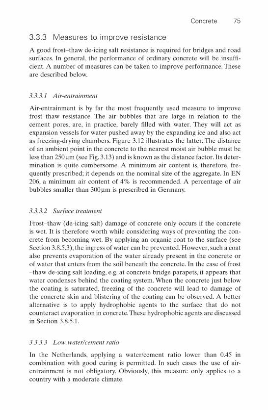
3.3.3 Measures to improve resistance
A good frost–thaw de-icing salt resistance is required for bridges and roadsurfaces. In general, the performance of ordinary concrete will be insuffi-cient. A number of measures can be taken to improve performance. Theseare described below.
3.3.3.1 Air-entrainment
Air-entrainment is by far the most frequently used measure to improvefrost–thaw resistance. The air bubbles that are large in relation to thecement pores, are, in practice, barely filled with water. They will act asexpansion vessels for water pushed away by the expanding ice and also actas freezing-drying chambers. Figure 3.12 illustrates the latter. The distanceof an ambient point in the concrete to the nearest moist air bubble must beless than 250 mm (see Fig. 3.13) and is known as the distance factor. Its deter-mination is quite cumbersome. A minimum air content is, therefore, fre-quently prescribed; it depends on the nominal size of the aggregate. In EN206, a minimum air content of 4% is recommended. A percentage of airbubbles smaller than 300 mm is prescribed in Germany.
3.3.3.2 Surface treatment
Frost–thaw (de-icing salt) damage of concrete only occurs if the concreteis wet. It is therefore worth while considering ways of preventing the con-crete from becoming wet. By applying an organic coat to the surface (seeSection 3.8.5.3), the ingress of water can be prevented. However, such a coatalso prevents evaporation of the water already present in the concrete orof water that enters from the soil beneath the concrete. In the case of frost–thaw de-icing salt loading, e.g. at concrete bridge parapets, it appears thatwater condenses behind the coating system. When the concrete just belowthe coating is saturated, freezing of the concrete will lead to damage of the concrete skin and blistering of the coating can be observed. A betteralternative is to apply hydrophobic agents to the surface that do not counteract evaporation in concrete.These hydrophobic agents are discussedin Section 3.8.5.1.
3.3.3.3 Low water/cement ratio
In the Netherlands, applying a water/cement ratio lower than 0.45 in combination with good curing is permitted. In such cases the use of air-entrainment is not obligatory. Obviously, this measure only applies to acountry with a moderate climate.
Concrete 75

76 Durability of engineering structures
After cooling down T < 0 °C.
Ice
(b)
T > 0 °C.
Air bubble
H2O
(a)
3.12 (a) Air bubble and pore system filled with water and air; (b) airbubble and pore system filled with ice, water and air.
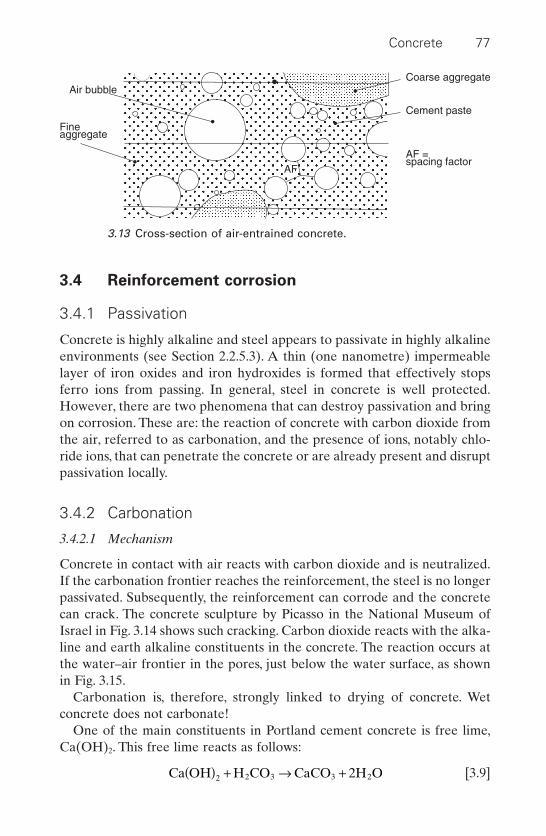
3.4 Reinforcement corrosion
3.4.1 Passivation
Concrete is highly alkaline and steel appears to passivate in highly alkalineenvironments (see Section 2.2.5.3). A thin (one nanometre) impermeablelayer of iron oxides and iron hydroxides is formed that effectively stopsferro ions from passing. In general, steel in concrete is well protected.However, there are two phenomena that can destroy passivation and bringon corrosion. These are: the reaction of concrete with carbon dioxide fromthe air, referred to as carbonation, and the presence of ions, notably chlo-ride ions, that can penetrate the concrete or are already present and disruptpassivation locally.
3.4.2 Carbonation
3.4.2.1 Mechanism
Concrete in contact with air reacts with carbon dioxide and is neutralized.If the carbonation frontier reaches the reinforcement, the steel is no longerpassivated. Subsequently, the reinforcement can corrode and the concretecan crack. The concrete sculpture by Picasso in the National Museum ofIsrael in Fig. 3.14 shows such cracking. Carbon dioxide reacts with the alka-line and earth alkaline constituents in the concrete. The reaction occurs atthe water–air frontier in the pores, just below the water surface, as shownin Fig. 3.15.
Carbonation is, therefore, strongly linked to drying of concrete. Wet concrete does not carbonate!
One of the main constituents in Portland cement concrete is free lime,Ca(OH)2. This free lime reacts as follows:
[3.9]Ca OH H CO CaCO 2H O2 2 3 3 2( ) + Æ +
Concrete 77
Air bubble
Fineaggregate
AF
Coarse aggregate
Cement paste
AF =spacing factor
3.13 Cross-section of air-entrained concrete.
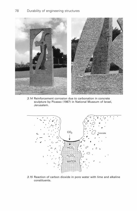
78 Durability of engineering structures
3.14 Reinforcement corrosion due to carbonation in concretesculpture by Picasso (1967) in National Museum of Israel,Jerusalem.
HCO2
CO2
H2CO3
WATER
Concrete
3.15 Reaction of carbon dioxide in pore water with lime and alkalineconstituents.

However, not only is the free lime carbonated, lime–silica gel, CSH-gel, themain binding component, is also converted. This reaction does not affectconcrete strength, but changes alkalinity and the pore system. In general,the pores in Portland cement (CEM I) concrete will become smaller. In thecase of cements containing additions, like fly ash, however, this can resultin a coarser pore system. Figure 3.16 schematically shows carbonation pro-gressing into concrete. As soon as the alkalinity decreases below pH 10,steel will no longer be passivated. In the case of exposure to constant relative humidity and temperatures, the carbonation frontier follows Fick’s second law and can be expressed as follows:
[3.10]
where: X = the penetration depth of the carbonation frontierA = constantt = time
Figure 3.17 illustrates this relationship. In practice, penetration occurs less quickly. This is due to the continuous changes in humidity and temperature, which slow down drying of the concrete and consequently carbonation.
3.4.2.2 Rate of carbonation, concrete parameters
The rate of carbonation depends on:
X A t=
Concrete 79
Concentrationof CO2
pH
~13.4
~8.3
Distance fromthe concretesurface
Distance fromthe concretesurface
3.16 Simplified model of carbonation penetration.
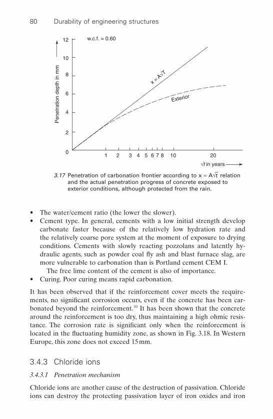
• The water/cement ratio (the lower the slower).• Cement type. In general, cements with a low initial strength develop
carbonate faster because of the relatively low hydration rate and the relatively coarse pore system at the moment of exposure to dryingconditions. Cements with slowly reacting pozzolans and latently hy-draulic agents, such as powder coal fly ash and blast furnace slag, aremore vulnerable to carbonation than is Portland cement CEM I.
The free lime content of the cement is also of importance.• Curing. Poor curing means rapid carbonation.
It has been observed that if the reinforcement cover meets the require-ments, no significant corrosion occurs, even if the concrete has been car-bonated beyond the reinforcement.10 It has been shown that the concretearound the reinforcement is too dry, thus maintaining a high ohmic resis-tance. The corrosion rate is significant only when the reinforcement islocated in the fluctuating humidity zone, as shown in Fig. 3.18. In WesternEurope, this zone does not exceed 15mm.
3.4.3 Chloride ions
3.4.3.1 Penetration mechanism
Chloride ions are another cause of the destruction of passivation. Chlorideions can destroy the protecting passivation layer of iron oxides and iron
80 Durability of engineering structures
12
10
8
6
4
2
01 2 3 4 5 6 7 8 10 20
w.c.f. = 0.60
÷t in years
x = A√T
Exterior
Pen
etra
tion
dept
h in
mm
3.17 Penetration of carbonation frontier according to x = A÷t–
relationand the actual penetration progress of concrete exposed toexterior conditions, although protected from the rain.
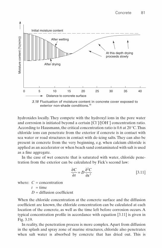
hydroxides locally. They compete with the hydroxyl ions in the pore waterand corrosion is initiated beyond a certain [Cl-]/[OH-] concentration ratio.According to Hausmann, the critical concentration ratio is 0.6 at 20°C.Thuschloride ions can penetrate from the exterior if concrete is in contact withsea water or road structures in contact with de-icing salts. They can also bepresent in concrete from the very beginning, e.g. when calcium chloride isapplied as an accelerator or when beach sand contaminated with salt is usedas a fine aggregate.
In the case of wet concrete that is saturated with water, chloride pene-tration from the exterior can be calculated by Fick’s second law:
[3.11]
where: C = concentrationt = timeD = diffusion coefficient
When the chloride concentration at the concrete surface and the diffusioncoefficient are known, the chloride concentration can be calculated at eachlocation of the concrete, as well as the time left before corrosion occurs. Atypical concentration profile in accordance with equation [3.11] is given inFig. 3.19.
In reality, the penetration process is more complex. Apart from diffusionin the splash and spray zone of marine structures, chloride also penetrateswhen salt water is absorbed by concrete that has dried out. This is
∂∂
=∂∂
Ct
DC
x
2
2
Concrete 81
At this depth dryingproceeds slowly
Initial moisture content
After wetting
After drying
0 5 10 15 20 25 30 35 40
Distance to concrete surface
Moi
stur
e co
nten
t (%
(m/m
))
3.18 Fluctuation of moisture content in concrete cover exposed toexterior non-shade conditions.10

schematically shown in Fig. 3.20. Transport then is much faster than trans-port by pure diffusion. After the water has been absorbed, concrete driesout again until attacked by a new splash of salt water. In Western Europeancountries, penetration due to salt water absorption appears to be restrictedto the outer 15mm. Beyond that 15mm, diffusion is the controlling mechanism. Models and computer programs are available to calculate chloride penetration, while taking account of these mechanisms.11
Another complicating factor in the modelling of chloride ingress in concrete is that part of the chloride is bound to the solid cement phase.In general, more than 50% of the chloride is bound. Only free chloride in the pore water poses a direct threat to the reinforcement. A further factor is that carbonation changes the pore structure and the binding capacity. This leads to a typical chloride penetration profile as shown in Fig. 3.21.12
3.4.3.2 Penetration factors
The chloride ion penetration rate is determined by the factors listed below.
82 Durability of engineering structures
Reinforcement
Criticallimit
Penetration depth (mm)
0 10 20 30 40 50
3
2
1
CI– c
onte
nt(%
by
mas
s of
cem
ent)
3.19 Typical chloride concentration profile.

Concrete 83
Absorptionof salt water
Diffusion
Cl–
Cl–
3.20 Transport of chloride ions by suction and diffusion.
Distance to concrete surface (mm)
Chl
orid
e co
nten
t
2.5
2.0
1.5
1.0
0.5
0 10 20 30 40 50 60 70 80
Carbonation frontier
3.21 Influence of carbonation on chloride profile according to Tuutti.12

The cement type
The diffusion rate can be extremely slow in blast furnace cement CEMIII/A, B, and C and Portland concrete with silica fume, yet it can beextremely fast in concrete with sulphate-resistant Portland cement of thesame water/cement ratio and strength class. This is mainly due to differ-ences in the pore structure of these hardened cements. The pore structureis coarse in sulphate-resistant Portland cement and fine in blast furnace slagcements and silica fume concrete.
Another difference is the capacity of hardened cements to bind chlorides,a capacity that is small in sulphate-resistant Portland cement. The effect onchloride initiation is shown in Fig. 3.22. It concerns a calculation made bythe author in 1981 for the building of the 25km long Saudi Arabia–BahrainCauseway (nowadays called the King Fahad Causeway).13 It shows the
84 Durability of engineering structures
400
360
320
280
240
200
160
120
80
40
0
0 20 40 60 80 100 120 140
III = Portland blast furnaceslag cement
I = Suphate-resistingPortland cement
II = Ordinary Portlandcement
Concrete cover (mm)
Initi
atio
n tim
e (y
ears
)
I: Dc = 4.5.10–12 m2/sII: Dc = 2.0.10–12 m2/s
III: Dc = 2.0.10–12 m2/s
3.22 Illustration of estimated corrosion initiation time due topenetration of chloride ions at 35°C for concrete produced withsulphate-resistant Portland cement (CEM 1 HS), ordinary Portlandcement (CEM I), and blast furnace slag cement with 65% byweight of slag (CEM III/B), respectively.13
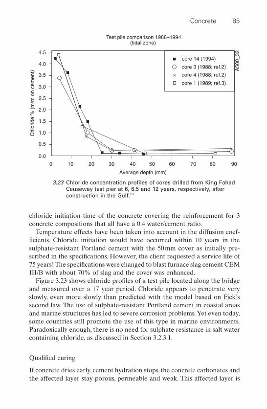
chloride initiation time of the concrete covering the reinforcement for 3concrete compositions that all have a 0.4 water/cement ratio.
Temperature effects have been taken into account in the diffusion coef-ficients. Chloride initiation would have occurred within 10 years in the sulphate-resistant Portland cement with the 50mm cover as initially pre-scribed in the specifications. However, the client requested a service life of75 years! The specifications were changed to blast furnace slag cement CEMIII/B with about 70% of slag and the cover was enhanced.
Figure 3.23 shows chloride profiles of a test pile located along the bridgeand measured over a 17 year period. Chloride appears to penetrate veryslowly, even more slowly than predicted with the model based on Fick’ssecond law. The use of sulphate-resistant Portland cement in coastal areasand marine structures has led to severe corrosion problems.Yet even today,some countries still promote the use of this type in marine environments.Paradoxically enough, there is no need for sulphate resistance in salt watercontaining chloride, as discussed in Section 3.2.3.1.
Qualified curing
If concrete dries early, cement hydration stops, the concrete carbonates andthe affected layer stay porous, permeable and weak. This affected layer is
Concrete 85
Average depth (mm)
0 10 20 30 40 50 60 70 80 90
4.5
4.0
3.5
3.0
2.5
2.0
1.5
1.0
0.5
0.0
Chl
orid
e %
(m
/m o
n ce
men
t)
core 14 (1994)
core 3 (1988; ref.2)
core 4 (1988; ref.2)
core 1 (1989; ref.3)
A50
0_32
Test pile comparison 1988–1994(tidal zone)
3.23 Chloride concentration profiles of cores drilled from King FahadCauseway test pier at 6, 6.5 and 12 years, respectively, afterconstruction in the Gulf.13

easy to penetrate. Such an effect can also be seen in the chloride profilesof Fig. 3.23. Penetration appears to have been fast for the first 10mm andhas subsequently slowed down considerably, perhaps even stopped.
The temperature
The higher the temperature, the faster penetration occurs. As the chloridediffusion coefficient increases, concrete dries out faster and the capacity tobind chloride decreases. Results from moderate climates should, therefore,be interpreted with caution when used in harsh climates.
3.4.4 Corrosion due to stray currents
Stray currents can also cause corrosion. The source of stray currents can bealternating current transmission lines from direct sources, such as fromdirect current traction systems, or cathodic protection systems that areoperated in the vicinity of the reinforced concrete. To avoid corrosion dueto stray currents, all reinforcement must be electrically connected and aspecial earthing system must be considered.
3.4.5 Corrosion propagation
Once the passivation layer dissolves, corrosion occurs and the corrosionpropagation phase starts, as illustrated in Figure 3.24.12 Even when corro-sion has been initiated, the corrosion rate can be very low and negligible.
86 Durability of engineering structures
Penetrationtowardsreinforcement
Degreeof cor-rosion
Acceptabledegree ofcorrosion
Propagation
Lifetimeor time before repair
Initiation
O2
(t1) (t2)
(CO2) Cl–
Ds
3.24 Schematic drawing of the corrosion process of steel inconcrete.12
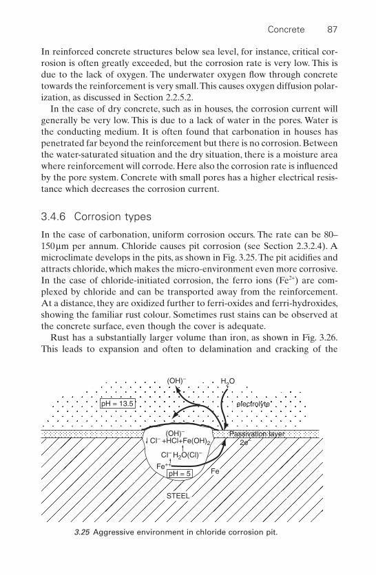
In reinforced concrete structures below sea level, for instance, critical cor-rosion is often greatly exceeded, but the corrosion rate is very low. This isdue to the lack of oxygen. The underwater oxygen flow through concretetowards the reinforcement is very small.This causes oxygen diffusion polar-ization, as discussed in Section 2.2.5.2.
In the case of dry concrete, such as in houses, the corrosion current willgenerally be very low. This is due to a lack of water in the pores. Water isthe conducting medium. It is often found that carbonation in houses haspenetrated far beyond the reinforcement but there is no corrosion. Betweenthe water-saturated situation and the dry situation, there is a moisture areawhere reinforcement will corrode. Here also the corrosion rate is influencedby the pore system. Concrete with small pores has a higher electrical resis-tance which decreases the corrosion current.
3.4.6 Corrosion types
In the case of carbonation, uniform corrosion occurs. The rate can be 80–150mm per annum. Chloride causes pit corrosion (see Section 2.3.2.4). Amicroclimate develops in the pits, as shown in Fig. 3.25. The pit acidifies andattracts chloride, which makes the micro-environment even more corrosive.In the case of chloride-initiated corrosion, the ferro ions (Fe2+) are com-plexed by chloride and can be transported away from the reinforcement.At a distance, they are oxidized further to ferri-oxides and ferri-hydroxides,showing the familiar rust colour. Sometimes rust stains can be observed atthe concrete surface, even though the cover is adequate.
Rust has a substantially larger volume than iron, as shown in Fig. 3.26.This leads to expansion and often to delamination and cracking of the
Concrete 87
pH = 13.5
(OH)– H2O
electrolyte
Passivation layer(OH)–
CI– +HCl+Fe(OH)2
CI– H2O(Cl)–
pH = 5Fe++
2e–
STEEL
Fe
3.25 Aggressive environment in chloride corrosion pit.

concrete. This will naturally happen first at a location where the coverquality is lowest or the microclimate most aggressive. The first crack is alsoa first warning. It gives us some time to analyse the problem. In the case ofchloride-initiated corrosion, this warning can be deferred because of theabove-discussed phenomenon of transporting the chloride away from thereinforcement towards the surface.
3.4.7 Preventive measures
Even in the most aggressive natural climates, reinforcement corrosion canbe avoided by the right choice of cement type, concrete composition, rein-forcement cover and adequate curing quality. Carbonation is not discussedin this section. Corrosion of steel reinforcement in concrete can be avoidedby simply following the standards in place and by meeting the requirementsof minimum cover.
3.4.7.1 Cement type
The binder type is of the utmost importance, as illustrated in Fig. 3.22. Con-crete with blast furnace slag cement (CEM III/B and CEM III/C), with apowder coal fly ash content of at least 30% fly ash, silica fume or other pozzolanic additions can show high resistance to chloride ingress. Maritimeconcrete structures in the Netherlands are almost exclusively built withblast furnace slag cement and their performance over a 75 year period isexcellent.14 Other Western European countries also have a long and posi-
88 Durability of engineering structures
Fe
Fe3O4
Fe(OH)2
Fe(OH)3
Fe(OH)3· 3H2O
0 1 2 3 4 5 6
(cm3)
3.26 Volume of various corrosion products in comparison with iron.
tive experience with this type of cement. The results shown in Fig. 3.23 forthe King Fahad Causeway between Saudi Arabia and Bahrain indicate thatperformance can be excellent in hot maritime climates also.
Silica fume is used in many countries as an addition to manufacturedhigh-durability concrete. An advantage is that the percentage of silica fumeis generally lower than 10%, which makes it more easily tradable than slagcement with slag percentages of up to 80%. A disadvantage is that experi-ence in practice is limited, while there are also some questions with respectto the critical corrosion concentration and the vulnerability to autogeneousshrinkage.
3.4.7.2 Water/cement ratio
Another important factor with respect to chloride penetration is thewater/cement ratio, although the effect of the water/cement ratio is muchless than that of the cement type. Thus the effect on the chloride diffusioncoefficient of decreasing the water/cement ratio of 0.5 to 0.35 is about afactor of 4, while changing the binder from Portland cement, CEM I, to oneof the binder types discussed in the previous section can make a differenceof a factor of 50.
In marine concrete structures, the water/cement ratio specified is mostlylower than 0.45 and can be as low as 0.3. The use of superplasticizers andwell-adjusted grain size distribution in the fine particle area are required toachieve these low water/cement ratios. Increasing the binder content is,of course, another possibility for decreasing the water/cement ratio. Thisincrease is restricted by the increase in hydration heat, hydration develop-ment, shrinkage and creep of the concrete, which makes the concrete moresensitive to cracking.
A reduction of the water/cement ratio can also be achieved by applyingcontrolled permeability formwork. A popular product has become apolypropylene liner on the formwork with the trade name Zemdrain, thewater at the surface drains partly into the liner, which reduces thewater/cement ratio of the skin of the concrete and consequently improvesthe carbonation and chloride penetration resistance.15
3.4.7.3 Cover
Figure 3.22 illustrates the importance of cover. In structures subject to chlo-ride loading, the cover has to be at least 50mm thick. One has to be awarethat the concrete skin is often of poorer quality than the concrete core dueto imperfect curing and so a layer of up to 10mm that is affected and offersless resistance to chloride ingress is not unusual.
Concrete 89
3.4.7.4 Curing
When concrete dries out, the cement stops reacting and the concrete car-bonates. The earlier drying out occurs during cement hydration giving amore negative effect on concrete. Careful curing according to specificationsis, therefore, of the utmost importance. In practice, this is not alwaysobserved.
Binder types with pozzolanic or latently hydraulic additions, such aspowder coal fly ash and slag are usually more vulnerable to curing than isPortland cement, CEM I.
3.4.7.5 Additional preventive actions
In countries where Portland cements are applied exclusively and the use ofcements with pozzolanic or latently hydraulic additions are not common,various preventive measures have been developed to protect the rein-forcement against chloride-initiated corrosion. Examples of such preven-tive measures are the addition of inhibitors or the use of epoxy-coatedrebars or of stainless steel reinforcement.
Inhibitors
Anodic inhibitors are applied in the United States. The most popular oneis calcium nitrite, Ca(NO2)2, which is mixed into the concrete. Once the rein-forcement starts corroding, nitrite oxidizes the ferro (Fe2+) ions, into ferri(Fe3+), thus forming a dense layer with hydroxyl ions, and this repairs thelocally disrupted passivation to some degree.
Chloride ions and nitrite ions compete with each other. A sufficient concentration of nitrite has to be present so as to attain a certain level ofprotection. One of the drawbacks of nitrite is that if the chloride concen-tration exceeds the effective nitrite concentration, pit corrosion can beaccelerated.
This uncertainty has probably restricted widespread use of calciumnitrite. Another reason for its restriction is the toxicity of nitrite. This hasprompted the development of less toxic inhibitors. Justness claims16 thatcalcium nitrate has a good potential as an inhibitor but is non-toxic. Organicadsorptive types that curb both anodic and cathodic reactions are also onthe market. Inhibitors are applied in North America but hardly at all inEurope.
Epoxy coated rebar
The use of the so-called fuse bonded epoxy coated rebar (powder coating)has become popular in North America. The system’s durability is, however,
90 Durability of engineering structures
increasingly contested. It appears that small defects in the coating canharbour pit corrosion. Measuring techniques that determine the quality ofthe epoxy coated rebar are lacking.17,18
Stainless steel rebar
Stainless steel is advocated as the universal remedy. A good grade of chloride-resistant stainless steel (see Section 2.4.3) can indeed be a techni-cally sound solution, although an expensive one! As discussed, there is noneed to use these expensive materials because the reinforcement is wellprotected by using plain concrete, applying the right cement type or addi-tion, cover thickness, and water/cement ratio.
3.4.8 Prestressed concrete
3.4.8.1 General
Prestressing of concrete is an elegant technique to exploit the high com-pressive strength of concrete in order to alleviate its weakness: the lowtensile strength. By loading the steel reinforcement in tension the concreteis put under compression. This technique is widely applied for buildingstructures. Post-tensioning and pre-tensioning stressing are distinguished.The term prestressing is applied to both.
In pre-tensioning, steel is stressed in a stiff steel frame before the con-crete is cast around it.
There are two main types of post-tensioning:
• Unbonded and bonded (grouted). An unbonded tendon is one in whichthe prestressing steel is not actually bonded to the concrete that sur-rounds it except at the anchorages. The most common unbondedsystems are monostrand (single strand) tendons, which are used in slabsand beams for buildings, parking structures and slabs-on-ground. Amonostrand tendon consists of a strand consisting of a number of wirescoated with a corrosion-inhibiting grease and encased in an extrudedplastic protective sheathing. The anchorage consists of an iron castingand a conical, two-piece wedge that grips the strand.
• Bonded systems. Here, two or more strands are inserted into a metal orplastic duct that is embedded in the concrete. When the concrete hasdeveloped a certain strength the strands are stressed with a large, multi-strand jack and anchored in a common anchorage device. The duct isthen filled with a cementing grout that provides corrosion protection tothe strand and bonds the tendon to the concrete surrounding the duct.Bonded systems are more commonly used in bridges, both in the super-structure and in cable-stayed bridges.
Concrete 91
With respect to durability prestressed concrete has advantages in compar-ison with ordinary reinforced concrete:
• There are no cracks.• There is less dynamic movement.
A disadvantage is that the durability of those structures depends stronglyon the durability of the prestressing steel and that failure can occur withoutany warning.
3.4.8.2 Deterioration mechanisms of prestressing steel
The failures observed in practice are due to stress corrosion cracking andhydrogen embrittlement. Both can occur suddenly and without any warningas discussed in Sections 2.3.2.10 and 2.3.2.11.19 The vulnerability of the pre-stressing steel for these types of failure is higher than for ordinary rein-forcement because high strength steels are in general more sensitive tostress corrosion and hydrogen embrittlement.
Corrosion can be initiated during the construction stage, during transportand on the site when the tendons are left unprotected; even contact withwater can induce corrosion. Contact with salt water or salt-laden air inmarine environments can be especially detrimental.
For the completed structure corrosion can be induced by:
• Chlorides; either in marine environments or where de-icing salts areapplied. Hot marine environments represent the most severe types ofexposure.
• Carbonation; the latter can occur if the grout in ducts is not filled com-pletely or the cover is of low quality. The failure of a part of the roof ofthe Berlin congress hall in 1980 was due to hydrogen embrittlementafter carbonation.20
The anchorages of prestressing tendons are vulnerable, especially in thecase of unbonded post-tensioned concrete, where stress transfer occurs inthis zone.
3.4.8.3 Prevention of corrosion
Construction of prestressed concrete
In the case of post-tensioned bonded concrete measures should be takento prevent early failure during the construction state. The tendons shouldbe protected from water and condensation during transport, storage andthe period in the post-tensioning ducts when tendons are not protected bythe grout. Examples of protection systems are packing in watertight plastic
92 Durability of engineering structures

with enclosed siccatives or a vapour-based inhibitor and use of greases thatshould be compatible with the grout applied. When the tendons are placedin the ducts no leakage of water should occur; and there should not be bleeding water from the surrounding concrete, because even this alka-line water can easily be neutralized by carbonation and then cause corro-sion. The tendons should not be left long unprotected by the grout in theduct.
In the case of grouting a full and complete filling up of the duct and com-plete embedment of the tendons are essential. The grouting technology ishighly developed and it requires skilled labour to execute the groutingoperation. The duct should be filled and full embedment of the strandsshould be achieved. Naturally, grouts should not contain any corrosive com-pounds such as chloride and thiocyanates.
Structures in use
In the case of aggressive environments concretes should be used with a highpenetration resistance to chlorides and high cover (see Section 3.4.7). Forpost-tensioned members the use of non-corroding dense ducts, such as poly-ethylene ducts, help to halt the progress of chlorides towards the tendons.This was, for instance, successfully applied in the building of the King FahadCauseway.21
Special attention should be given to joints between prestressed membersand to the anchorages of the tendons. Anchorage appears to be often vul-nerable to chloride penetration along the interface of the filled-in interfaceof box-outs. Good adherence of the box-out fill up mortar and the concreteshould be warranted. Especially vulnerable are the anchorages of unbondedpost-tensioned systems, because they are the sole areas of stress transferbetween tendons and concrete. Applying sufficient cover, a low water/cement ratio and good curing can prevent carbonation problems. It shouldbe realized that repair of affected prestressed systems is difficult, if notimpossible, to carry out (see Section 7.3.3 for further information).22
3.5 Principles of protection and repair of
concrete structures
3.5.1 General
The principles for protection and repair of concrete structures as given inEN 1504, Part 9, General principles for the use of products and systems arefollowed in this chapter. Protection systems and repair products are dis-cussed in Sections 3.6, 3.7, 3.8 and 3.9 and two practical repair cases aregiven in Section 3.10. EN 1504 distinguishes between principles and
Concrete 93
methods related to defects in concrete and those related to reinforcementcorrosion. The emphasis will be on the latter in this section. The repair ofdefects in concrete structures will be discussed briefly.
3.5.2 Principles and methods related to defects in concrete
EN 1504, Principles 1 to 7, listed in Table 3.6, cover defects in concrete orconcrete structures caused by the following actions that take place eitherseparately or in combination:
1 Mechanical actions, e.g. impact, overloading, movement caused by set-tlement, and blast.
2 Chemical and biological actions from the environment.3 Physical actions, e.g. frost–thaw action, thermal cracking, moisture
movement, salt crystallization and erosion.
Principle 1 [PI]; protection against ingress
CracksCrack widths that do not exceed the limit, for instance 0.2 or 0.3mm, andthat are kept in check by the reinforcement are allowed in many reinforcedconcrete applications. Cracks may form for several reasons, e.g. due tomechanical loading, plastic shrinkage, thermal contraction, hydration heator as a result of overloading.
It must then be established which are the causes of cracking and the effecton the structure of ingress or seepage. If an adverse effect is found, treat-ment can be carried out using one or more of Methods 1.1 to 1.7, given inTable 3.6.Thus a crack below the water table will not have an adverse effecton reinforced concrete durability, but a similar crack above the water tablecan be detrimental.A crack due to thermal contraction of concrete may notaffect the performance of a large foundation slab, but is does affect thewater-tightness of a tunnel.
Note: Some cracks form in hardened concrete as a result of corrosion thatis already under way. These cracks usually form over the reinforcement andare often the first visual sign that there is a corrosion problem. Crackscaused by corrosion cannot be stopped simply by filling or sealing. Thesedefects should be repaired by methods that take account of the corrosioncause, according to Principles 7 to 11, as discussed in Section 3.5.3.
The possibility of further cracking after applying Methods 1.2 and 1.4 mustbe taken into consideration. Information on live and dead cracks is givenin EN 1504–5. In the case of live cracks, account must be taken of the fact
94 Durability of engineering structures
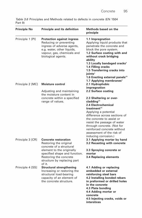
Concrete 95
Table 3.6 Principles and Methods related to defects in concrete (EN 1504 Part 9)
Principle No Principle and its definition Methods based on the
principle
Principle 1 [PI] Protection against ingress 1.1 Impregnation
Reducing or preventing Applying liquid products that ingress of adverse agents, penetrate the concrete and e.g. water, other liquids, block the pore system.vapour, gas, chemicals and 1.2 Surface coating with and
biological agents. without crack bridging
ability
1.3 Locally bandaged cracksa
1.4 Filling cracks
1.5 Transferring cracks into
jointsa
1.6 Erecting external panelsab
1.7 Applying membranesa
Principle 2 [MC] Moisture control 2.1 Hydrophobic
impregnation
Adjusting and maintaining 2.2 Surface coating
the moisture content in concrete within a specified 2.3 Sheltering or over-
range of values. claddingab
2.4 Electrochemical
treatmentab
Applying a potentialdifference across sections of the concrete to assist or resist the passage of waterthrough concrete. (Not forreinforced concrete withoutassessment of the risk ofinducing corrosion.)
Principle 3 [CR] Concrete restoration 3.1 Applying mortar by hand
Restoring the original 3.2 Recasting with concrete
concrete of a structural element to the originally 3.3 Spraying concrete or
specified shape and function. mortar
Restoring the concrete 3.4 Replacing elements
structure by replacing partof it.
Principle 4 [SS] Structural strengthening 4.1 Adding or replacing
Increasing or restoring the embedded or external
structural load-bearing reinforcing steel bars
capacity of an element of 4.2 Installing bonded rebars
the concrete structure. in preformed or drilled holes
in the concrete
4.3 Plate bonding
4.4 Adding mortar or
concrete
4.5 Injecting cracks, voids or
interstices

that completely filling up those cracks will always lead to new crackingwithin the crack filler on the crack filler/concrete interface or within theconcrete. Injection products and methods are discussed in Section 3.7.
Principle 2 [MC]; moisture control
GeneralPrinciple 2 is relevant when the moisture content in concrete should belower than a critical value beyond which deterioration could occur.All Prin-ciple 2 methods require the carrying out of a maintenance programme inaccordance with EN 1504, Part 10. Since the protection systems may notlast for the design life of the concrete structure, renewal and repairabilityare important considerations in the choice of protection system. Methodsand products are discussed in Sections 3.8 and 3.9.7.
Control of alkali–aggregate reactionsThe main cause of alkali–aggregate reactions, besides the presence of sig-nificant quantities of alkali–reactive aggregate particles and alkalis, is thepresence of sufficient quantities of moisture. By reducing moisture to a con-trolled low limit, alkali–silica gel will not be able to expand sufficiently tocause the concrete to crack.
96 Durability of engineering structures
Table 3.6 Continued
Principle No Principle and its definition Methods based on the
principle
4.6 Filling cracks, voids or
interstices
4.7 Prestressing – (post
tensioning)a
Principle 5 [PR] Physical resistance 5.1 Overlays or coatings
Increasing resistance to 5.2 Impregnation
physical or mechanicalattack.
Principle 6 [RC] Resistance to chemicals 6.1 Overlays or coatings
Increasing resistance of the 6.2 Impregnation
concrete surface to deteriorations by chemicalattack.
a These methods may make use of products and systems not covered by theEN 1504 series and are not discussed in this bookb Inclusion of methods in EN 1405 does not imply these methods have beenapproved

The alkali–aggregate reaction takes place over a certain period of time,after which the rate of expansion tends to decrease. After this period,protection and repair may be of the same type as for concrete with non-expanding cracks. In order to make sure that the cracks are of the non-expanding type, the crack width should be measured over an adequateperiod of time.
Protection against frost–thaw damageWhere defects are caused only by the more severe frost–thaw action of saltwater, and not by fresh water, protection can be achieved in accordancewith Principle 1 [PI] by preventing ingress of chlorides.
Principle 3 [CR]; concrete restoration
The mortar or concrete can be cement-bound, polymer-modified cementi-tious, or polymer-bound (see Section 3.6).
Principle 4 [SS]; structural strengthening
It is essential when using Principle 4 that repairs should never producestresses that are harmful to the original structure. Method 4.7, wheretendons are installed through or around a concrete structural element andsubsequently tensioned so as to confine the element or carry the loadsapplied to it, can create internal stresses which increase the effects of deterioration. With the exception of the strengthening of structures withfibre-reinforced composites (Section 5.4), methods for structural strength-ening are not discussed in this book. Reference is made to the relevant literature.23,24
Principle 5 [PR]; physical resistance
Methods 5.1 ‘overlays or coatings’ and 5.2 ‘impregnation’ that serve tostrengthen the physical resistance of the concrete surface are discussed inSection 3.8.
Principle 6 [RC]; resistance to chemicals
Concrete in accordance with EN 206 and products and systems in accor-dance with the EN 1504 series can be used for concrete that has beenattacked in the past by chemicals or is being attacked at present by thosechemicals covered by the provisions of EN 206 (see Table 3.1). Productsand systems for protecting concrete are discussed in Section 3.8.
Concrete 97

3.5.3 Principles and methods related to reinforcement corrosion
According to EN 1504, Part 9, Principles 7 to 11, in Table 3.7 cover rein-forcement corrosion is caused by:
1 Physical loss of the protective concrete cover.2 Chemical loss of alkalinity in the protective concrete cover as a result
of the reaction with atmospheric carbon dioxide (‘carbonation’)(Section 3.4.2).
3 Contamination of the protective concrete cover with corrosive agents(usually chloride ions) that were incorporated in the concrete when itwas mixed or that have penetrated into the concrete from the environ-ment (Section 3.4.3).
4 Stray electrical currents conducted or induced in the reinforcementfrom neighbouring electrical installations (Section 3.4.4).
In general, corrosion caused by chloride ingress is more difficult to coun-teract than corrosion by carbonation. Protection and repair in situationswhere reinforcement corrosion poses a risk are based on the Principlesbelow. Where reinforcement corrosion exists or there is a risk that corro-sion will occur in the future, one or more of the corrosion protection orrepair Principles 7 to 11 below, shall form the basis of the method applied.In addition to the above, the concrete itself shall be repaired where necessary, according to Principles 1 to 6.
Principle 7 [RP]; preserving or restoring passivity
GeneralAll methods of restoring passivity are effective only to a certain depth andthere may be a risk of contamination from the environment and adjacentcontaminated concrete.
Method 7.1 increasing cover to reinforcement with additionalcementitious mortar or concreteBy increasing the cover with a cementitious mortar or concrete an additional barrier against ingress is shaped. Furthermore, in the case of carbonation by diffusion re-alkalization can occur both from the additionalcover as well as from the background concrete, see also Method 7.4.Chloride profiles existing in the original cover will level out not onlytowards the core of the concrete in the direction of the reinforcement but also towards the additional cover which decreases the threat for the reinforcement.
98 Durability of engineering structures

Concrete 99
Table 3.7 Principles and Methods related to reinforcement corrosion (EN 1504Part 9)
Principle No Principle and its definition Some examples of methods
based on the principle
Principle 7 [RP] Preserving or restoring 7.1 Increasing the
passivity reinforcement cover with
additional cementitious
Creating chemical conditions mortar or concrete
in which the surface of thereinforcement is maintained 7.2 Replacing contaminated
in, or is returned to, a or carbonated concrete
passive condition. 7.3 Electrochemical
re-alkalization of carbonated
concretea
7.4 Re-alkalization of
carbonated concrete by
diffusion
7.5 Electrochemical chloride
extractiona
Principle 8 [IR] Increasing resistivity 8.1 Limiting moisture
content by surface
Increasing the electrical treatments, coatings or
resistivity of the concrete. sheltering
Principle 9 [CC] Cathodic control 9.1 Limiting oxygen content
(at the cathode) by
Creating conditions in which saturation or surface
potentially cathodic areas of coatingb
reinforcement are unable to drive an anodic reaction.
Principle 10 [CP] Cathodic protection 10.1 Applying electrical
potentiala
Principle 11 [CA] Control of anodic areas 11.1 Applying reinforcement
coatings containing active
Creating conditions in which pigments
potentially anodic areas of the reinforcement are unable 11.2 Applying barrier
to take part in the corrosion coatings to the
reaction. reinforcement
11.3 Applying inhibitors to
the concreteab
a These methods may make use of products and systems not covered by theEN 1504 seriesb Inclusion of methods in EN 1504 Part 9 does not imply these methods havebeen approved
Method 7.2 replacing contaminated or carbonated concreteIn some cases, it may be necessary to replace both reinforcement and con-crete.Attention should be given to the possibility that adjacent to the repairarea the concrete can still be contaminated, which later on can lead to cor-rosion. It is possible that the repaired area can act as a cathodic area, whichaggravates the corrosion progress around the repaired area. This is knownas the incipient anode effect. It is often desirable to protect the repairedand adjacent concrete against ingress, as outlined in Principle 1. This is oneof the principles applied to the repair of the Deira–Shindagah tunnel, asdiscussed in Section 3.10.1.
Method 7.3 electrochemical re-alkalization of carbonated concreteIn this method a strongly alkaline paste (soda, cellulose fibres, gel etc.) isapplied on the surface of the concrete. An anode mesh is embedded in thepaste and electrically connected to the reinforcement via a DC source. Arelatively high voltage is applied. The alkaline solution is drawn into theconcrete due to electrolytic osmotic forces. Concurrently also the pH israised by the cathodic reaction at the reinforcement. Because the alkalinebuffer built up is small the method has to be completed with a CO2 resis-tant surface treatment.
Method 7.4 re-alkalization of carbonated concrete by diffusionThis method requires the application of cementitious concrete or mortar tothe surface of carbonated concrete so that it can be re-alkalized throughdiffusion, see Method 7.1. It depends upon conditions that permit sufficientdiffusion and on the ability of the repair layer to prevent carbonation atthe reinforcement throughout the required design life of the member. Itshould be noted that in case of carbonated concrete around the reinforce-ment, repassivation is possible by increasing the cover with a concrete layeror a barrier coating. Moreover, as soon as moisture fluctuations cease, thecorrosion rate will slow down substantially.
Method 7.5 electrochemical chloride extractionFigure 3.27 shows schematically the extraction progress of chlorides fromconcrete. The voltage applied over the temporary anode at the concrete/reinforcement surface is substantially higher than in the case of cathodicprotection. Electrochemical chloride removal is only possible for concretesituated between the reinforcement and the surface and immediately sur-rounding the reinforcement. There is a risk of recontamination of this con-crete from ions within the concrete from behind the reinforcement.
100 Durability of engineering structures

Principle 8 [IR]; increasing resistivity
Principle 8 [IR] requires the moisture content of the concrete to be lowenough to restrict the flow of ions to a very low value. Inside dry buildings,corrosion is seldom a problem, even if concrete is carbonated at the reinforcement depth. This is because the low moisture content in enclosedbuildings tends to raise concrete resistivity to a level where the corrosionrate is insignificant.
Under suitable circumstances, it may be possible to create similar condi-tions externally by reducing the moisture content through the applicationof ventilated external claddings, water-repellent surface treatments or pore-filling impregnation or surface coatings. When such methods of protectionare used, it is necessary to consider the specific application in detail so asto ensure that moisture cannot be created by condensation at cold spotsand that it cannot enter the concrete from the ground, faulty drainage orother sources. Moisture must, however, be allowed to escape freely.
Principle 9 [CC]; cathodic control
Principle 9 [CC] requires the access of oxygen to all potentially cathodicareas to be restricted to the point where corrosion cells are disabled andcorrosion is prevented by inactivity of the cathodes.
Saturation of the whole of a self-contained reinforced concrete unit, witha reinforcement that has no electrical connection with reinforcement in anyother unit and that has oxygen access, is an example of how this principle
Concrete 101
H2OCI–
OH– + H2
OH– –
–
+
Electrolyte Temporary anode
ConcreteReinforcement
3.27 Extraction of chlorides from concrete.
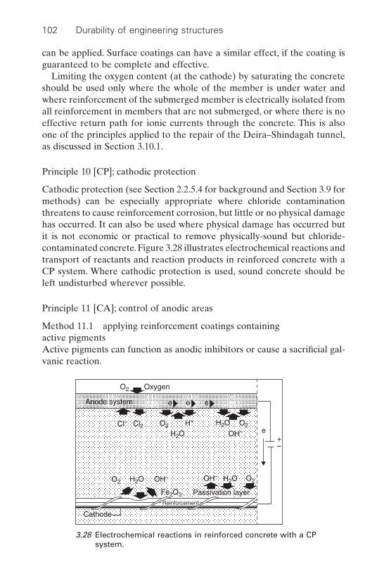
can be applied. Surface coatings can have a similar effect, if the coating isguaranteed to be complete and effective.
Limiting the oxygen content (at the cathode) by saturating the concreteshould be used only where the whole of the member is under water andwhere reinforcement of the submerged member is electrically isolated fromall reinforcement in members that are not submerged, or where there is noeffective return path for ionic currents through the concrete. This is alsoone of the principles applied to the repair of the Deira–Shindagah tunnel,as discussed in Section 3.10.1.
Principle 10 [CP]; cathodic protection
Cathodic protection (see Section 2.2.5.4 for background and Section 3.9 formethods) can be especially appropriate where chloride contaminationthreatens to cause reinforcement corrosion, but little or no physical damagehas occurred. It can also be used where physical damage has occurred butit is not economic or practical to remove physically-sound but chloride-contaminated concrete. Figure 3.28 illustrates electrochemical reactions andtransport of reactants and reaction products in reinforced concrete with aCP system. Where cathodic protection is used, sound concrete should beleft undisturbed wherever possible.
Principle 11 [CA]; control of anodic areas
Method 11.1 applying reinforcement coatings containing active pigmentsActive pigments can function as anodic inhibitors or cause a sacrificial gal-vanic reaction.
102 Durability of engineering structures
Cathode
Reinforcement
Anode system
OxygenO2
O2
O2
O2
O2
H2O
Fe2O3
H2OH2O
H2OCl2Cl–
OH–
OH–OH–
H+
Passivation layer
e
e e e
+–
3.28 Electrochemical reactions in reinforced concrete with a CPsystem.
Inhibitors are chemical agents that discourage the formation of anodicregions on the reinforcement.
There is controversy about the medium- and long-term effectiveness ofthis type of treatment.
Coating the reinforcement with a substance that is an electrical conduc-tor with a lower electrode potential than steel causes the cations of thecoating material (rather than the steel) to dissolve under corrosive condi-tions. Ions of the coating metal are also attracted to any accidentallyexposed (negatively charged) parts of the steel, at which locations theyrepair the protective layer. A typical example is the use of zinc powder asa filler. Other methods include phosphating with diluted phosphoric acid,followed by a sealing coat (see also Section 2.5.3).
Method 11.2 applying barrier coatings to the reinforcementIsolating the reinforcement from the surrounding concrete with a coatingthat is an electrical insulator should prevent metal cations from escapingfrom the steel and should also prevent incoming anions from being dis-charged there. This method can only be effective if the steel is clean andthe coating complete, i.e. the bar must be completely encapsulated and thecoating undamaged (see Section 2.5.3). The method should only be con-templated if the whole of the circumference of the bar can be coated. Theeffect of coating on the bond should be considered. A barrier coating of thereinforcement was applied in the repair of the Deira–Shindagah tunnel, asdiscussed in Section 3.10.1. It should be emphasized that effective repairshould not depend solely on a barrier coating applied on the reinforcementin a marine environment when the problems with epoxy-coated rebar rein-forced concrete are recognized.17,18
Method 11.3 applying inhibitors to concrete by impregnation or diffusionInhibitors can be applied as a surface treatment or by electrochemicalmeans. They may also be added to repair products and systems. Inhibitorsact by chemically changing the surface of the steel or by forming a passivefilm on top. Inhibitors applied to the surface of the concrete rely on theirability to penetrate the concrete down to the steel level so as to be effec-tive, given the fact that concrete is permeable to inhibitors that generatehigh vapour pressure and have good diffusion characteristics. This methodis under development and will not be discussed in this book.
Concrete 103
3.6 Repair mortars
3.6.1 Classification
Repair mortars are classified here according to binder type:
• Cement-bound mortars are referred to as cement concrete (CC)mortars. These are cement-bound mortars with less than 5% of poly-mers and other organic admixtures in relation to the cement mass.
• Polymer-modified cement-bound mortars are referred to as polymer-cement concrete (PCC) mortars. These are cement-bound mortars with5 to 20% of polymer in relation to the cement mass.
• Resin-bound mortars are referred to as polymer concrete (PC) mortars.The resin is the only binder in these mortars.
These mortars contain aggregates, additions, fillers and admixtures.
3.6.2 Cement-bound mortars, CC
Cement-bound mortars are applied by casting, trowelling and spraying.
3.6.2.1 Casting
Casting is used for larger repairs of horizontal and vertical surfaces, forinstance when a full edge of a balcony is repaired, as will be discussed inSection 3.10.2. A problem with casting application can be the adhesion tothe old concrete. Due to shrinkage of the repair mortar, shear or tensileforces are generated at the interface and debonding occurs occasionally.
Sometimes non-shrinkage or swelling mortars are advocated to avoid thedrying shrinkage stresses of cementitious mortars. However, one must beaware that these mortars swell during the initial phase of hardening, whenthe Young’s modulus is still low. Drying shrinkage will still occur afterswelling and will only be compensated by previous swelling when com-pressive stresses have built up in the mortar. This will only occur to a sub-stantial degree when mortar is enclosed in all directions, which is usuallynot the case when repairing.
3.6.2.2 Sprayed concrete
Sprayed concrete is often applied in repair work. A distinction can be made into dry sprayed concrete (dry shotcrete or gunite concrete) and wetsprayed concrete.
In the dry process, the solid constituents are mixed dry. The dry mixtureis pumped to a spray nozzle where water and other fluid constituents are
104 Durability of engineering structures

added. The mixture is then sprayed against the substrate with great force.Part of the material is rebound, especially the larger particles of the mortar.This leads to a cement-rich layer at the substrate surface, as shown in Fig.3.29, which improves adhesion.
Wet sprayed concrete has become more popular because the workingconditions are better than for the dry sprayed concrete. Rebound and dustdevelopment are substantially less.
In sprayed concrete, adhesion strength on the substrate is an importantproperty. A typical requirement is an average adhesion strength of at least1.3N/mm2 with a minimum value of 0.6N/mm2.
3.6.3 Polymer-modified cement mortars, PCC
To improve the rather poor performance of repairs with cement/sand patch-ing mortars and, simultaneously, maintain their positive effects, especiallythe (re)passivating capacity and the fact that cement mortars have proper-ties such as Young’s modulus and linear expansion coefficient that aresimilar to the concrete substrate, polymer-modified mortars (also calledlatex-cement mortars) have grown popular in repair work.
These polymers consist of elastomeric polymers or thermoplastic poly-mers such as polyvinylidene chloride, polyvinyl propionate, styrene butadi-ene, styrene acrylates and polyvinyl versatate.Thermosetting resins are alsoused, mainly water-emulsified epoxy resins. When applied with a percent-age of less than 5% by weight of cement, these mortars are referred to as
Concrete 105
1000
800
600
400
2000 10 20 30 40
Distance to substrate surface (mm)
Cem
ent c
onte
nt (
kg/m
3 )
3.29 Cement content as a function of the distance to the substratesurface for dry sprayed concrete.
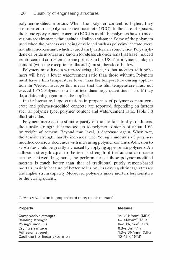
polymer-modified mortars. When the polymer content is higher, they are referred to as polymer cement concrete (PCC). In the case of epoxies,the name epoxy cement concrete (ECC) is used.The polymers have to meetvarious requirements that include alkaline resistance. Some of the polymersused when the process was being developed such as polyvinyl acetate, werenot alkaline-resistant, which caused early failure in some cases. Polyvinyli-dene chloride mortars are known to release chloride ions that have inducedreinforcement corrosion in some projects in the US. The polymers’ halogencontent (with the exception of fluoride) must, therefore, be low.
Polymers must have a water-reducing effect, so that mortars with poly-mers will have a lower water/cement ratio than those without. Polymersmust have a film temperature lower than the temperature during applica-tion. In Western Europe this means that the film temperature must notexceed 10°C. Polymers must not introduce large quantities of air. If theydo, a defoaming agent must be applied.
In the literature, large variations in properties of polymer cement con-crete and polymer-modified concrete are reported, depending on factorssuch as polymer type, polymer content and water/cement ratio. Table 3.8illustrates this.1
Polymers increase the strain capacity of the mortars. In dry conditions,the tensile strength is increased up to polymer contents of about 10% by weight of cement. Beyond that level, it decreases again. When wet,the tensile strength hardly increases. The Young’s modulus of polymer-modified concrete decreases with increasing polymer contents. Adhesion tosubstrates could be greatly increased by applying appropriate polymers. Anadhesion strength equal to the tensile strength of the substrate concrete can be achieved. In general, the performance of these polymer-modifiedmortars is much better than that of traditional purely cement-basedmortars, mainly because of better adhesion, less drying shrinkage stressesand higher strain capacity. Moreover, polymers make mortars less sensitiveto the curing quality.
106 Durability of engineering structures
Table 3.8 Variation in properties of thirty repair mortars1
Property Measure
Compressive strength 14–69N/mm2 (MPa)Bending strength 6–14N/mm2 (MPa)Young’s modulus 8–25kN/mm2 (GPa)Drying shrinkage 0.3–2.0mm/mAdhesion strength 1.3–3.6N/mm2 (MPa)Coefficient of linear expansion 10–17 ¥ 10-6/K

In some countries, the use of polymer-modified sprayed concrete iscommon practice, such as in Germany. It is referred to as SPCC.
3.6.4 Resin bound mortars, PC
Polymer-bound mortars or polymer concrete (PC) are often used in hand-patching. Epoxy resins, acrylics or polyurethanes are usually used as abinder in these mortars. Polyester resins are not recommended because oftheir high hardening shrinkage, their moisture sensitivity as well as theirproneness to saponification when applied to concrete.Adhesive primers arealways applied in this type of mortar. These often contain anti-corrosiveagents if treating the reinforcement, although it is not certain that the useof these agents is necessary.
The patching operation is rather critical because polymer mortar has tobe applied to the polymer primer when wet.
In a field study in the Netherlands, most of the polymer mortars investi-gated showed debonding, this was due to insufficient preparation of the substrate. Certain other factors, such as differences in temperature-expansion and exceeding the glass–rubber transition temperature of theepoxy, could also have contributed to this. It is often thought that applyinga PC mortar on a cleaned-up rusted bar will prevent renewed corrosion butthis is not usually the case. Open space is always present around the barand the reinforcement is not passivated.
3.7 Crack repair methods
3.7.1 General
Cracks must be repaired for the following reasons:
• To reduce or prevent ingress of adverse agents, e.g. water, other liquids, vapour, gas, chemicals and biological agents; Principle 1 in Table3.6.
• To increase or restore the structural load-bearing capacity of an elementof the concrete structure; Principle 4 in Table 3.6.
While crack injection agents are usually applied other measures can or must be taken occasionally in order to repair a crack. In deciding upon themethod to be applied, much depends on which function must be restoredand whether or not the cause of cracking is still present and may be reactivated. In the case of live cracks, one must be aware that completelyfilling up those cracks by injection will always lead to new cracking withinthe crack filler, on the interface with the cracked concrete or within the old
Concrete 107
concrete.*1 In such cases, increasing or restoring the structural bearingcapacity is not possible using the methods described in this section andstructural strengthening with tendons or plate bonding must be considered.
3.7.2 Crack injection agents
Requirements for concrete crack injection products are specified in EN1504, Part 5. The product used depends not only on the function to be dis-charged, but also on the conditions of the crack, notably the presence orabsence of water. The type of crack must be distinguished; it can be dry,humid, water transporting without pressure or water transporting underpressure. Under the more complicated conditions of water pressure, wateringress at the crack is closed off first, for instance by a polyurethane resinthat forms a foam in contact with water. Subsequently, the crack is filled upwith a massive resin. Table 3.9 presents a survey of the injection agentsapplied.2
3.7.3 Other methods that prevent ingress through cracks
In the case of cracks that have to be sealed off to reduce or prevent ingressof adverse agents, the following methods can be used to seal off the joints:
• Applying elastic sealants. Cracks can be widened at the surface toreduce the stresses in the sealant due to movements of the concrete, asshown in Fig. 3.30.
• Sealing at the surface with flexible rubber strips, as shown in Fig. 3.31.
3.8 Protective surface treatments
3.8.1 General
A survey of concrete surface protection systems is given in this section. Suchissues as why and how to protect the surface, the general requirementsregarding surface protective agents and commercially available agents areconsidered.
108 Durability of engineering structures
*It is often thought that filling up of the crack with a flexible injection agent willsolve the problem. However, materials that show flexible behaviour (low modulusof elasticity, high deformation capacity and elastic behaviour) in uniaxial loadingbehave inflexibly if three-dimensionally restrained as in a crack.
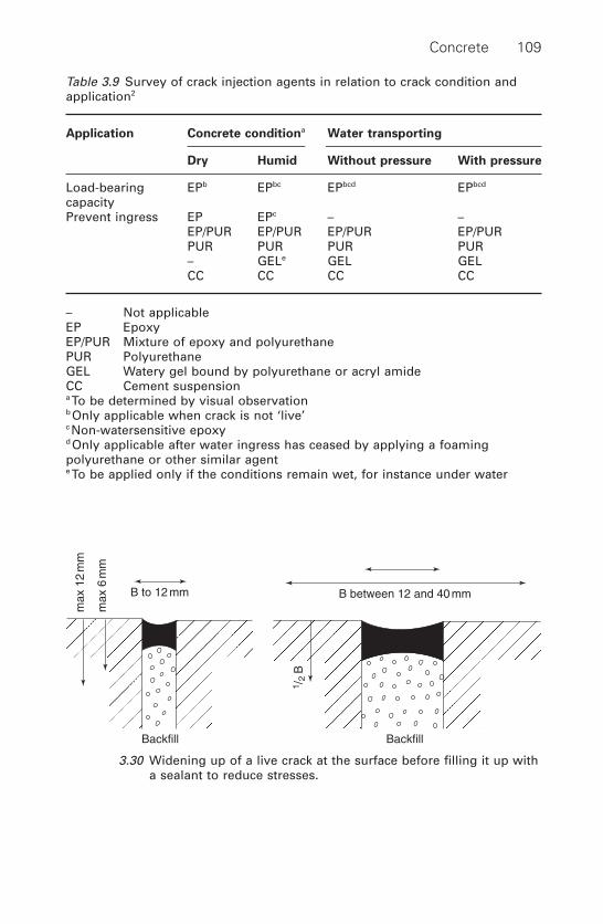
Concrete 109
B between 12 and 40 mm
BackfillBackfill
B to 12 mm
max
12
mm
max
6 m
m
1 /2
B
3.30 Widening up of a live crack at the surface before filling it up witha sealant to reduce stresses.
Table 3.9 Survey of crack injection agents in relation to crack condition andapplication2
Application Concrete conditiona Water transporting
Dry Humid Without pressure With pressure
Load-bearing EPb EPbc EPbcd EPbcd
capacityPrevent ingress EP EPc – –
EP/PUR EP/PUR EP/PUR EP/PURPUR PUR PUR PUR– GELe GEL GELCC CC CC CC
– Not applicableEP EpoxyEP/PUR Mixture of epoxy and polyurethanePUR PolyurethaneGEL Watery gel bound by polyurethane or acryl amideCC Cement suspensiona To be determined by visual observationb Only applicable when crack is not ‘live’c Non-watersensitive epoxyd Only applicable after water ingress has ceased by applying a foamingpolyurethane or other similar agente To be applied only if the conditions remain wet, for instance under water

3.8.2 Types
The following types of surface protection can be distinguished according toEN 1504, Part 2, Surface Protection Systems (see Fig. 3.32).
• Hydrophobic impregnation.• Impregnation that partially or completely fills up the pores.• Coating.
In practice, hydrophobic impregnation and coating are the most important.When concrete is made water-repellent by hydrophobing, the walls of the
concrete pores are lined with a hydrophobic agent by means of the suctionof the agent into the concrete. This process is sometimes aided by previousartificial drying. Hydrophobing does not significantly influence transport ofwater vapour, but can considerably reduce water absorption.
110 Durability of engineering structures
Impregnate/hydrophobe
Impregnate/partly filling up
Impregnate/fully filling up (sealing)
Surface layers
3.32 Types of surface protection.
Adhesive
Concrete
Rubber band
Steel plate
Steel sheet (glued)
3.31 Closing off live crack to prevent adverse agent ingress.

In cases of impregnation and filling up of pores, the concrete surface ispenetrated by an agent that fills up the pores. Impregnation can be per-formed by making use of the absorptive capacity of concrete, which can bepromoted by drying the surface and/or evacuating the air. A distinction canbe made between agents that fill up the pores by reacting with constituentsof concrete and agents that do not react with concrete.
At locations where the pores of the concrete surface layer become totallyfilled up by impregnation, the process is referred to as sealing. By applyinga coating, the concrete protection is based on the layer covering the con-crete. Coatings are distinguished by thickness:
• Thin coatings: layers less than 100 mm thick.• Thick coatings: layers between 100 and 500mm thick.• Plasters both with an organic and an inorganic basis that have thick-
nesses of between 500 mm and 5mm.
A survey of the various methods of surface protection is given in Table 3.10. The last four surface protection methods are not considered in thischapter.
3.8.3 Reasons for protection
There are a number of reasons for protecting concrete, as explained inSection 3.5, Tables 3.6, and 3.7 and summarized in Table 3.11.
3.8.4 Durability of protection
3.8.4.1 General
An important aspect with respect to protective measures is their durabil-ity. Durability can be affected by external factors that can cause degrada-tion of the protection agent. These include UV radiation and oxidation. Ofspecial interest, however, is the internal compatibility of the substrate, i.e.of the ‘old’ concrete with the surface protection system applied.
3.8.4.2 Degradation by UV radiation and oxidation
Organic materials degrade when exposed to UV radiation and to air.Hydrophobic agents will lose their performance within 10 to 15 years.Epoxy coatings will start to deteriorate at the surface and the polymer struc-ture will break down leaving a whitish and dusty surface showing the fillers.Although this does not usually affect the protective performance of thecoating, it is often unacceptable for aesthetic reasons.A better UV-resistanttop coat, such as a polyurethane coat, is therefore frequently applied (seeSections 3.8.5.3 and 3.10.1).
Concrete 111
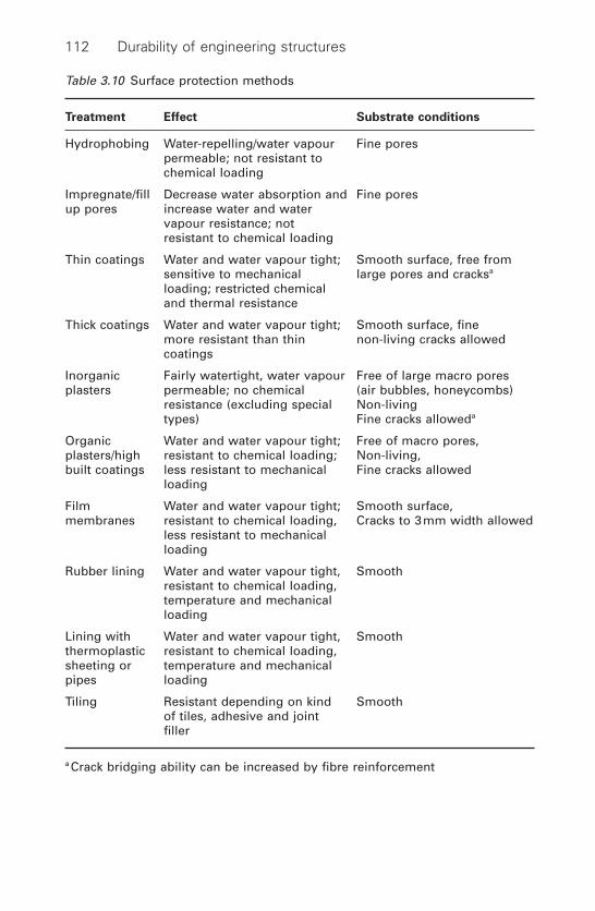
112 Durability of engineering structures
Table 3.10 Surface protection methods
Treatment Effect Substrate conditions
Hydrophobing Water-repelling/water vapour Fine porespermeable; not resistant tochemical loading
Impregnate/fill Decrease water absorption and Fine poresup pores increase water and water
vapour resistance; not resistant to chemical loading
Thin coatings Water and water vapour tight; Smooth surface, free from sensitive to mechanical large pores and cracksa
loading; restricted chemical and thermal resistance
Thick coatings Water and water vapour tight; Smooth surface, fine more resistant than thin non-living cracks allowedcoatings
Inorganic Fairly watertight, water vapour Free of large macro pores plasters permeable; no chemical (air bubbles, honeycombs)
resistance (excluding special Non-livingtypes) Fine cracks alloweda
Organic Water and water vapour tight; Free of macro pores,plasters/high resistant to chemical loading; Non-living,built coatings less resistant to mechanical Fine cracks allowed
loading
Film Water and water vapour tight; Smooth surface,membranes resistant to chemical loading, Cracks to 3mm width allowed
less resistant to mechanicalloading
Rubber lining Water and water vapour tight, Smoothresistant to chemical loading,temperature and mechanicalloading
Lining with Water and water vapour tight, Smooththermoplastic resistant to chemical loading,sheeting or temperature and mechanicalpipes loading
Tiling Resistant depending on kind Smoothof tiles, adhesive and jointfiller
a Crack bridging ability can be increased by fibre reinforcement
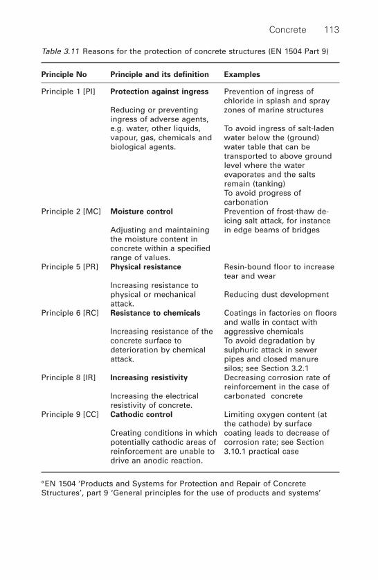
Concrete 113
Table 3.11 Reasons for the protection of concrete structures (EN 1504 Part 9)
Principle No Principle and its definition Examples
Principle 1 [PI] Protection against ingress Prevention of ingress of chloride in splash and spray
Reducing or preventing zones of marine structuresingress of adverse agents, e.g. water, other liquids, To avoid ingress of salt-laden vapour, gas, chemicals and water below the (ground) biological agents. water table that can be
transported to above ground level where the waterevaporates and the saltsremain (tanking)To avoid progress ofcarbonation
Principle 2 [MC] Moisture control Prevention of frost-thaw de-icing salt attack, for instance
Adjusting and maintaining in edge beams of bridgesthe moisture content inconcrete within a specifiedrange of values.
Principle 5 [PR] Physical resistance Resin-bound floor to increase tear and wear
Increasing resistance to physical or mechanical Reducing dust developmentattack.
Principle 6 [RC] Resistance to chemicals Coatings in factories on floorsand walls in contact with
Increasing resistance of the aggressive chemicalsconcrete surface to To avoid degradation by deterioration by chemical sulphuric attack in sewer attack. pipes and closed manure
silos; see Section 3.2.1Principle 8 [IR] Increasing resistivity Decreasing corrosion rate of
reinforcement in the case of Increasing the electrical carbonated concreteresistivity of concrete.
Principle 9 [CC] Cathodic control Limiting oxygen content (at the cathode) by surface
Creating conditions in which coating leads to decrease of potentially cathodic areas of corrosion rate; see Section reinforcement are unable to 3.10.1 practical casedrive an anodic reaction.
a EN 1504 ‘Products and Systems for Protection and Repair of ConcreteStructures’, part 9 ‘General principles for the use of products and systems’

3.8.4.3 Compatibility with concrete substrate
Frost–thaw de-icing salt damage
When the protective treatment renders the surface very dense, as in thecase of sealings or moisture-impermeable coatings, a high moisture contentcan build up under the protective layer that can make the concrete vul-nerable to frost attack.This appears to occur especially on surfaces with fre-quent frost–thaw cycles,25 e.g. edge beams of bridge decks exposed tode-icing salts. To avoid these problems, Künzel has proposed the followinglimit values:
[3.12]
where:
W = water absorption coefficientSd = water vapour diffusion resistance
To express this concept in words: the protection must not allow waterabsorption, but must permit water vapour to leave the concrete. Figure
W
S
S W
£ ◊( )£◊ £ ◊( )
0.5kg m h
2m
0.1kg m h
2 1 2
d
d1 2
114 Durability of engineering structures
00
0.3
0.5
1
2
0.1 0.2 0.3 0.4
W [kg/m2 · h0.5]
W.Sd = 0.1 [kg/m · h0.5]
W.Sd = 0.2 [kg/m · h0.5]
Sd
(m)
0.5
Silicon coatingSilicon resin/high built coating
Dispersion coatingElastomeric coatingSilicate/dispersion paintLime cement paste
3.33 Künzel relation between water absorption coefficient (W ) andwater vapour diffusion resistance (Sd) and positions of variousprotective agents.26
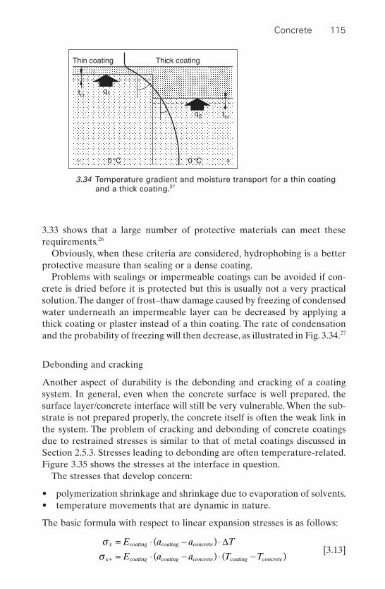
3.33 shows that a large number of protective materials can meet these requirements.26
Obviously, when these criteria are considered, hydrophobing is a betterprotective measure than sealing or a dense coating.
Problems with sealings or impermeable coatings can be avoided if con-crete is dried before it is protected but this is usually not a very practicalsolution.The danger of frost–thaw damage caused by freezing of condensedwater underneath an impermeable layer can be decreased by applying athick coating or plaster instead of a thin coating. The rate of condensationand the probability of freezing will then decrease, as illustrated in Fig. 3.34.27
Debonding and cracking
Another aspect of durability is the debonding and cracking of a coatingsystem. In general, even when the concrete surface is well prepared, thesurface layer/concrete interface will still be very vulnerable. When the sub-strate is not prepared properly, the concrete itself is often the weak link inthe system. The problem of cracking and debonding of concrete coatingsdue to restrained stresses is similar to that of metal coatings discussed inSection 2.5.3. Stresses leading to debonding are often temperature-related.Figure 3.35 shows the stresses at the interface in question.
The stresses that develop concern:
• polymerization shrinkage and shrinkage due to evaporation of solvents.• temperature movements that are dynamic in nature.
The basic formula with respect to linear expansion stresses is as follows:
[3.13]s
sx coating coating concrete
x coating coating concrete coating concrete
E a a T
E a a T T
= ◊ -( ) ◊= ◊ -( ) ◊ -( )+
D
Concrete 115
Thin coating Thick coating
tcr
tcr
q1
0 °C– +0 °C
q2
3.34 Temperature gradient and moisture transport for a thin coatingand a thick coating.27
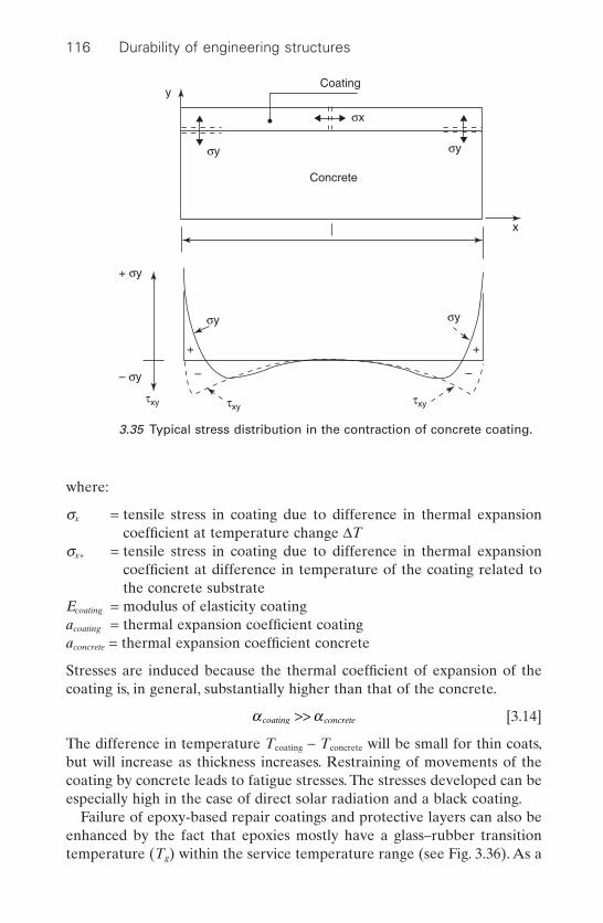
where:
sx = tensile stress in coating due to difference in thermal expansioncoefficient at temperature change DT
sx+ = tensile stress in coating due to difference in thermal expansioncoefficient at difference in temperature of the coating related tothe concrete substrate
Ecoating = modulus of elasticity coatingacoating = thermal expansion coefficient coatingaconcrete = thermal expansion coefficient concrete
Stresses are induced because the thermal coefficient of expansion of thecoating is, in general, substantially higher than that of the concrete.
[3.14]
The difference in temperature Tcoating - Tconcrete will be small for thin coats,but will increase as thickness increases. Restraining of movements of thecoating by concrete leads to fatigue stresses. The stresses developed can beespecially high in the case of direct solar radiation and a black coating.
Failure of epoxy-based repair coatings and protective layers can also beenhanced by the fact that epoxies mostly have a glass–rubber transitiontemperature (Tg) within the service temperature range (see Fig. 3.36). As a
a acoating concrete>>
116 Durability of engineering structures
Coatingy
Concrete
x
σy σy
σy
σx
σy
+ σy
– σy
τxy τxyτxy
+ +
– –
3.35 Typical stress distribution in the contraction of concrete coating.

consequence, the coating can show ‘plastic’ deformation at temperaturesabove Tg. When subsequently cooled down suddenly, for instance by rain,the deformation becomes more or less frozen in and this induces stresses.This phenomenon is repeated over time so that fatigue failure can occurafter a certain period. A protective polymer material in a Western European climate must, therefore, have a Tg of at least 65°C.
Crack bridging
In the case of cracks in concrete, only dead cracks can be successfullybridged by coatings.
Live cracks cannot be bridged unless the cracks are widened and the areato be bridged is made larger so that stresses in the coat are reduced (seeSection 3.7). A coating system on concrete can never bridge a newly devel-oping crack.
Saponification
An important condition for every protecting agent to be applied on con-crete is that it must be resistant to the highly alkaline environment of con-crete. A well-known binder used in the past that was not alkaline-resistantwas polyvinyl acetate.
Concrete 117
1010
109
108
107
106
105
104
103
Tg = 55 °C
Temperature
Mod
ulus
of e
last
icity
3.36 Glass–rubber transition temperature (Tg) of a typical epoxy resin.
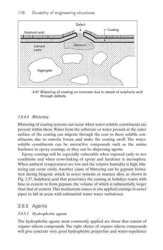
3.8.4.4 Blistering
Blistering of coating systems can occur when water-soluble constituents arepresent within them. Water from the substrate or water present at the outersurface of the coating can migrate through the coat to these soluble con-stituents, due to osmotic forces, and make the coating swell. The water-soluble constituents can be unreactive compounds such as the aminehardener in epoxy coatings, or they can be dispersing agents.
Epoxy coatings will be especially vulnerable when exposed early to wetconditions and when cross-linking of epoxy and hardener is incomplete.When ambient temperatures are low and the relative humidity is high, blis-tering can occur easily. Another cause of blistering can be gypsum forma-tion during biogenic attack in sewer systems or manure silos, as shown inFig. 3.37. Sulphuric acid that penetrates the coating at holidays reacts withlime in cement to form gypsum, the volume of which is substantially largerthan that of cement.This mechanism causes in situ applied coatings in sewerpipes to fail in areas with substantial waste water turbulence.
3.8.5 Agents
3.8.5.1 Hydrophobic agents
The hydrophobic agents most commonly applied are those that consist oforgano–silicon compounds. The right choice of organo–silicon compoundswill give concrete very good hydrophobic properties and water-repellence
118 Durability of engineering structures
Sulphuric acid
Defect
Coating
Gypsum
Aggregate
Cementpaste
Aggregate
3.37 Blistering of coating on concrete due to attack of sulphuric acidthrough defects.
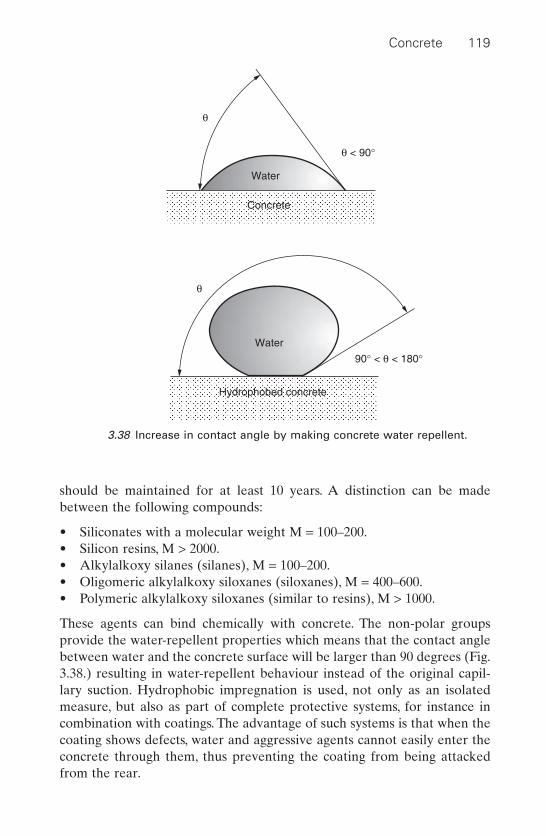
should be maintained for at least 10 years. A distinction can be madebetween the following compounds:
• Siliconates with a molecular weight M = 100–200.• Silicon resins, M > 2000.• Alkylalkoxy silanes (silanes), M = 100–200.• Oligomeric alkylalkoxy siloxanes (siloxanes), M = 400–600.• Polymeric alkylalkoxy siloxanes (similar to resins), M > 1000.
These agents can bind chemically with concrete. The non-polar groupsprovide the water-repellent properties which means that the contact anglebetween water and the concrete surface will be larger than 90 degrees (Fig.3.38.) resulting in water-repellent behaviour instead of the original capil-lary suction. Hydrophobic impregnation is used, not only as an isolatedmeasure, but also as part of complete protective systems, for instance incombination with coatings. The advantage of such systems is that when thecoating shows defects, water and aggressive agents cannot easily enter theconcrete through them, thus preventing the coating from being attackedfrom the rear.
Concrete 119
Water
Water
Concrete
Hydrophobed concrete
90° < q < 180°
q < 90°
q
q
3.38 Increase in contact angle by making concrete water repellent.
Siliconates
Siliconates are water-soluble or alcohol-soluble products (often with about40% of solids). When applied to concrete they react with carbon dioxideaccording to the reaction:
[3.15]
The R-group in the reaction formula is ethyl or propyl. To be effective, sil-iconates need carbon dioxide from the air. The K2CO3 released during thereaction with carbon dioxide may blemish the concrete but blemishing willbe temporary because it will be washed away by rain. Siliconates are seldomused for concrete surface protection.
Silicon resins
The second generation of water-repellent impregnants for concrete or otherstone-like building materials are the silicon resins. These resins are dis-solved in an aliphatic-soluble agent (typically containing about 5% ofsolids). This agent does not have the disadvantage of K2CO3 formation. Theresin reacts and is able to bond (cross-link) with the pore walls in place. Adisadvantage is that this resin can only be applied effectively on dry mate-rials with relatively coarse pores and these silicon resins can easily lead tosticky surfaces. They are not very suitable for application on concrete,mainly because the pores in this material are too fine.
Silanes
Alkylalkoxy silanes are dissolved in aliphatic or aromatic solvents. Thesilane content is relatively high, i.e. 40%. Moisture and a catalyst arerequired so as to enable the reaction to polysiloxanes. Concrete catalyzesthe polymerization.
The advantages of silanes in comparison with hydrophobic agents are asfollows:
• Better and deeper impregnation as a consequence of the low-viscositysolvent when compared to siliconates and the small molecules in rela-tion to silicon resins.
• The high percentage of active material, which is about 40%, as com-pared to 5 to 10% for silicon resins.
R
OK
SiHOCO2
–K2CO3SiHO OHOH silicone resin
R
OH
condensation
evaporationH2O
potassium siliconate
120 Durability of engineering structures
A disadvantage of silanes is that the material itself is volatile and can evap-orate together with the solvent, which makes the impregnation results veryweather dependent.
As a result of environmental pressure to reduce the evaporation ofvolatile organic compounds this type of treatment is no longer consideredacceptable in many countries.
Oligomeric alkylalkoxy siloxanes
To overcome the problem of evaporation of silanes, slightly polymerizedsilanes have been developed. These are known as olygomeric alkylalkoxysiloxanes, or siloxanes for short. The advantages of silanes have been main-tained, while the agents are less volatile. Siloxanes are available as solutionsin aliphatic agents or in alcohols. Their active material content rangesbetween 5 and 10%. The reaction is:
Concrete 121
R
OR
Si SiOR¢O OR¢ HO
+H2O+cath
–R¢OH
condensation
evaporation
R
OR¢ n = 1 – 4 n = 1 – 4 solvent
R
OH
Si SiO OH silicone resin
R
OH
[3.16]
Polymeric alkylalkoxy siloxanes
When silanes or siloxanes are polymerized further, long chain moleculesare developed. These polymer chains look very much like silicon resins, butare very sticky if no catalyst is applied. Polymeric alkylalkoxy siloxane arerarely used for concrete.
Silicon micro-emulsions
To overcome the environmental drawbacks of volatile organic solvents,micro-emulsions of silicon resins have been developed. Micro-balls of thesilicon resin are dispersed in water and the emulsion particles are smallenough to penetrate the pores.
3.8.5.2 Impregnation/filling up of pores
There are various impregnating agents available to fill up pores. Since concrete degradation often happens through the pores, this filling-up canmake the concrete less vulnerable. Only filling up with organic compoundsis discussed here.

The monomer, methacrylic-acid-methyl ester, easily penetrates dry con-crete. Once it has penetrated, it can be polymerized to form polymethyl-methacrylate (PMMA). In Germany, this method is used to restore orpreserve statues. The procedure for this preservation is as follows:
• Drying.• Evacuating.• Impregnating under pressure.• Heating up for hardening.
This method may show good results, but is restricted in its applicationbecause the size of the objects is governed by maximum limits. For concretestructures that cannot be evacuated and impregnated under pressure,results are generally rather poor because the impregnation does not fully fill up the pores and the required drying can cause cracks in the concrete.
Another organic compound that can be applied to impregnation is a one-component polyurethane. This involves a prepolymer that polymerizesfurther by reacting with moisture from the air or from the concrete.Concrete must be relatively dry during application to prevent excessivefoaming.
3.8.5.3 Coatings
In general, coatings comprise the following constituents:
• Binders.• Fillers (sometimes).• Pigments.• Additives.• Dispersing agents.• Solvents/diluents.
Binding is achieved through polyaddition or polymerization reactionsbetween the binding components (resins) or by drying as a result of evap-oration of the solvents and dispersing agents. The most important resins forconcrete structure protection are:
• Epoxy resins (EP): Epoxy resins usually provide good adhesion to concrete. Epoxy resins show minor polymerization shrinkage and areresistant to light chemical attack. However, they do not show a goodresistance to UV radiation (see Section 3.8.4.2).
To reduce the emission of volatile organic solvents, new epoxy coat-ings have been developed, for instance the so-called high built epoxycoats. Some problems with these new types of coats are discussed inSection 2.5.3.1.
122 Durability of engineering structures
• Two component polyurethanes (PUR): These adhere well to dry concrete surfaces, are almost shrinkage-free and are resistant to lightchemical attack. However, they are not very resistant in high alkalineenvironments and must therefore not be applied to surfaces that will becontinuously wet, unless an alkaline resistant primer is used. PUR coat-ings usually show a good resistance to UV radiation and are often usedas topcoats on epoxy resin base coats. PUR resins occasionally show dis-coloration (yellowing).
• Tar epoxy and tar PUR resins: These have some advantages, such ashigher flexibility in comparison to EP and better alkaline resistancewhen compared with PUR.A disadvantage is that they do not have sucha good resistance to UV radiation, oxidation and temperature extremes.Tar is banned in some countries (e.g. the Netherlands), because of thepresence of aromatic compounds.
• Polymethylmethacrylate (PMMA): PMMA resins show very goodadherence to concrete substrates. However, there is considerable shrink-age during polymerization of the polymer. Other features are their highmechanical strength and a good resistance to light chemical attack.
Drying types of binders are:
• Acrylics: in solution as well as in dispersion. Acrylics generally have agood adherence to concrete and a good resistance to alkalis, oxidationand weathering.
Further drying type agents are the following: chlorinated rubber, cyclo-rubber, vinylchloride copolymers, vinylfluoride copolymers, silicon resinsand polymeric alkylalkoxy siloxanes.The latter are applied not only to coat-ings, but also to impregnation, as discussed previously. Combinations ofdrying binders are also available on the market, such as acrylics combinedwith polyvinyl(tetra)fluoride.
3.9 Cathodic protection systems
3.9.1 General
Cathodic protection (French: protection cathodique, German: kathodischeKorrosionschutz, Dutch: kathodische bescherming) is a well-establishedanti-corrosion method for protecting steel exposed to aggressive liquids(e.g. sea water) and soils. Over the last decades, cathodic protection of steel-reinforced concrete structures has also become popular.28 Cathodic protec-tion seems to provide a reliable way to stop the corrosion process. In theUnited States, the Federal Highway Administration (FHWA) has come tothe following conclusion: ‘The only rehabilitation technique that has proven
Concrete 123
to stop corrosion in salt contaminated bridge-decks regardless of the chlo-ride content of concrete is cathodic protection.’29
The European Standard EN 12696 Cathodic Protection of Steel in Con-crete, Part 1, Atmospherically Exposed Concrete specifies performancerequirements both for existing and new structures. In practice, cathodic pro-tection is usually applied to existing structures suffering from reinforcementcorrosion. However, it is also used occasionally in new structures, e.g. byensuring electrical continuity on the steel reinforcement so that later oncathodic protection systems can easily be applied if required (see Section2.5.5).
3.9.2 Components
Cathodic protection systems with impressed current comprise the follow-ing components:
• A DC source.• An anode system.• A conductive electrolyte: concrete. The moisture content has a domi-
nant influence on conductivity.• A cathodic system: the steel reinforcement that must be electrically
continuous.• Electrical connecting cables that must be mechanically and chemically
durable.• Control and monitoring devices (reference electrodes, data compilers,
control units, etc.).
3.9.3 Anodes
The anodic system serves to supply the protecting current homogeneously.It has to meet the following requirements:
• It must be able to resist the mechanical, physical and chemical influ-ences of the environment.
• The lifetime must be longer than that of the covering layer, with aminimum of at least 20 years.
• The anode surface must be large enough to ensure that the currentdensity is sufficiently low to prevent failure of the system due to degra-dation of the anode or its interface layer in the surrounding concrete.
• It must be economically feasible.
3.9.3.1 Types of anode system
Anode systems that can be distinguished are:
124 Durability of engineering structures

• Conductive overlays: a layer acting as an anode covering the entire con-crete surface.
• Distributed anodes: discrete anodes that are spread evenly over the con-crete surface. Only part of the concrete surface is covered with activeanode material.
• Sacrificial metal layer: a covering metal layer that acts as a sacrificialanode.
Conductive overlays
Anodes that cover the entire surface of the concrete usually consist of acombination of primary and secondary anodes. The primary anode consistsof an inert metal. The secondary anode is an overlay consisting of a mortar,asphalt, or paint made conductive by adding carbon particles or consistingof a conductive polymer.
Examples of systems of this type are:
• Silicon iron anodes in combination with an overlay of conductiveasphalt. This is the oldest cathodic protection system of concrete. Theasphalt is made conductive by applying coke-breeze as a filler. Theprimary anodes are 300mm discs, 10mm thickness or 150 ¥ 230mm2
squares on which a conductive asphalt overlay is applied as a secondaryanode. The system is shown in Fig. 3.391 and has been used on bridgedecks in the United States since 1973. The system can only be appliedon top of horizontal surfaces.
• Meshed AD-wire of titanium often applied with a mixed rare earthmetal oxide film at the surface. The meshed AD-wires are covered witha conductive asphalt or conductive cement mortar.
Concrete 125
Reinforcement Concrete
Asphalt concrete Cokes asphalt Iron–silicon anode
D.C.source
3.39 Cathodic protection in a bridge deck. The iron–silicon anodeshave been embedded in a layer of conductive coke breezeasphalt.1

• Conductive paint (coating) systems. A series of conductors that act asprimary anodes on the concrete surface to dissipate the current. Theconductors must be of a material that resists anodic reactions, e.g.platinum-coated or platinum-clad titanium or niobium with a coppercore, or mixed metal oxide-coated titanium.They are fixed to the surfaceand sometimes protected by glass fibre mats over which a conductivepaint is applied as a secondary anode, as shown in Fig. 3.40. The paintis a dense coating made conductive by using graphite as a filler. Con-ductive polymers are also used. For aesthetic reasons, the black paint isoften covered with paint in the desired colour. This type of anode isappropriate for both ceilings and vertical and horizontal surfaces, butnot for surfaces that are exposed to wear and tear. The durability of thispaint system is estimated to be 10years. After that period, the concretemust be cleaned and coated with a new paint system. Advantages ofpaint systems are the relative ease of application, the ease of repair ofpossible defects, and the favourable ratio of the anode surface to theconcrete surface (one to one). Because of the latter factor, acid deteri-oration of the concrete below the paint coat will proceed relativelyslowly due to the low current density at the anode. However, minordegradation at the interface can severely damage the effectiveness ofthe system. In addition, a combination of a dense paint system with awater-rich concrete layer underneath will show sensitivity to de-icingsalts (see Section 3.8.4.3).
A practical case of a conductive paint system is discussed in Section 3.10.2.
126 Durability of engineering structures
Glass-fibre mat
Platinum anode
Conducting coating
Reinforced concrete
3.40 Principle of covering anode system with conductive paint.

Sacrificial anodes
An example of a sacrificial anode is the flame-sprayed zinc anode. A zinccoat of about 200 mm is sprayed onto the concrete and connected electri-cally to the reinforcement. This is known as a sacrificial anode because it does not need an external potential source. Another type of sacrificialanode occurs where a zinc foil is adhered to the concrete surface.
3.9.3.2 Durability
For the sake of durability, all parts of a cathodic protection system mustperform well throughout the design life. Some defects have appeared in a number of pioneering projects. These include: corroding of connectingcables on primary anodes, damage of the electrical control unit, erosion ofconducting asphalt layers, debonding of a sprayed concrete cover anddegradation of graphite-loaded polymer protection around copper wires.Not all of them are typical of cathodic protection systems. However, atten-tion needs to be paid to a number of phenomena that occur in concretefitted with an activated cathodic protection system.
Anode consumption
One of the possible degradation mechanisms takes place at the anodewhere various reactions occur as previously described in this chapter. Ifgraphite is used for anode cables, conductive mortars etc., the followingreactions can occur:
[3.17]
This means that the anode will slowly lose its thickness. The anodic currentdensity should, therefore, be restricted and the maximum anodic value rec-ommended by NACE is 0.1A/m2 current density. The titanium mesh anodeappears to behave considerably better in this respect.
Acid production
Another durability aspect of cathodic protection is the production of acidat the anode. As a consequence of the reactions previously described in thischapter, alkalinity at the anode/concrete interface will decrease, thusincreasing acidity. The anode materials may show very good resistance toacid. However, the surrounding cement mortar will not be resistant to acidformation. It is likely that a thin layer of concrete will be degraded.
2C O 2CO
C O CO2
2 2
+ Æ+ Æ
Concrete 127
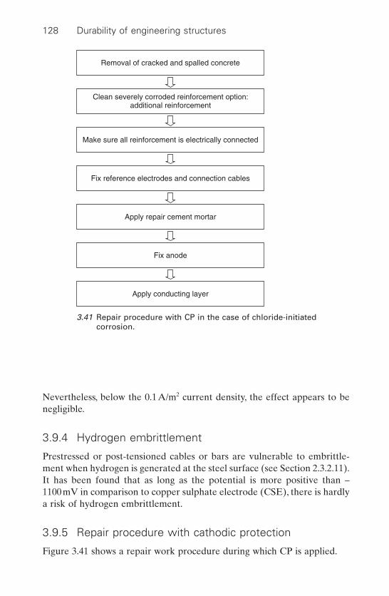
Nevertheless, below the 0.1A/m2 current density, the effect appears to benegligible.
3.9.4 Hydrogen embrittlement
Prestressed or post-tensioned cables or bars are vulnerable to embrittle-ment when hydrogen is generated at the steel surface (see Section 2.3.2.11).It has been found that as long as the potential is more positive than –1100mV in comparison to copper sulphate electrode (CSE), there is hardlya risk of hydrogen embrittlement.
3.9.5 Repair procedure with cathodic protection
Figure 3.41 shows a repair work procedure during which CP is applied.
128 Durability of engineering structures
Removal of cracked and spalled concrete
Make sure all reinforcement is electrically connected
Fix reference electrodes and connection cables
Apply repair cement mortar
Fix anode
Apply conducting layer
Clean severely corroded reinforcement option:additional reinforcement
3.41 Repair procedure with CP in the case of chloride-initiatedcorrosion.

3.9.6 Protection criteria
Various cathodic protection criteria for steel-reinforced concrete are advo-cated. The following criteria are given in EN 12696-1:
• An instant off potential (measured between 0.1 s and 1 s after switchingon the d.c. circuit) that is more negative than –720mV with respect toAgIAgCl/0.5M KCl.
• A potential decay over a maximum 24 hour period of at least 100mVfrom instant off.
• A potential decay over an extended period (typically 24 hours or longer)of at least 150mV from the instant off subject to a continuing decay andthe use of reference electrodes for measurements extended beyond a 24 hour period.
Overprotection must be avoided, not because of the increased cost due to elevated currents that do not usually exceed a 100W per thousand m2
of concrete surface, but because overprotection results in high current densities with a subsequent risk to the durability of the system.
3.9.7 Pulsed electro-osmosis
Electro-osmosis is a technology for drying concrete between electrodesembedded in the concrete and located at the concrete surface. The solidCSH–gel concrete surface is negatively charged and attracts positive ionsfrom the pore water. When a voltage is applied to the positive anode andnegative cathode electrodes, an electrical field is created between them.Consequently, the positive ions are attracted to the negative cathode anddrag the water with them. Locating a positive electrode close to the rein-forcement and a negative electrode at a distance from the reinforcementcan reduce humidity at the reinforcement. Polarization can then be avoidedby applying a pulsed voltage over the electrodes with a short rest period ofno applied voltage.
It has been claimed that the humidity can be decreased to a level lowerthan 60 to 70%, which is a level below which corrosion is stopped. This cor-responds to the Principle 8 ‘increasing resistivity’ of Table 3.7. The patentedmethod is offered in combination with a pulsed cathodic protection systemof the reinforcement, in which case both cathodic protection and theincreased resistivity of the drying concrete will contribute to decreased cor-rosion. The method is also recommended to counteract alkali silica expan-sion that corresponds to the Principle 2 ‘moisture control’, Method 2.4‘electrochemical treatment’ of Table 3.6.
Concrete 129

3.10 Practical cases of repair
3.10.1 Repair of the Deira–Shindagha tunnel in Dubai
3.10.1.1 Case description
A sea arm cuts off Dubai from the Arabian Gulf and, in 1975, a 561m longtunnel crossing the Dubai Creek was completed. A cross-section of thetunnel construction is shown in Fig. 3.42. The concrete was cast in place andconsisted of a sulphate-resistant Portland cement, porous limestone, coarseaggregate, beach sand with occasional chloride fractions, and tap water.Thefree water/cement ratio varied and could be as high as 0.6. The concretestructure was built in sections with a rubber water stop in the dilation joints and construction joints. The space in the dilations joints was filled upwith bituminized cork and finished with a Neferma strip.The exterior of thetunnel was covered with Bitu-Thene sheets that were to act as a water andsalt ingress barrier. A latex-cement (PC) coating with an aesthetic functionwas applied on the concrete inner-wall.
During construction, the cofferdam on top of the already constructedtunnel section slipped away under water pressure and damaged the water-impermeable Bitu-Thene layers. Although repairs were carried out, thismay have caused permanent damage.
130 Durability of engineering structures
Shindagha
Sun vizors
Entrance to the pedestrian andservice tunnel
A
A
Pedestrian tunnel
Servicetunnel
3.66 m 9.22 m
Cross section A-A
Sun vizors
North boreDeira
South bore
Total length 929.6 m
18 x 9.15 m 60 x 9.15 m 22 x 9.15 m
9.22 m
South bore North bore
North bore
3.42 Schematic view of the Deira–Shindagha tunnel in Dubai.

3.10.1.2 Causes of damage
Soon after completion, water leakage of Creek water through the joints wasobserved and reinforcement corrosion was reported within a few years.Obviously, this was due to the local presence of chloride-contaminatedbeach sand and to the highly permeable character of the concrete appliedwith respect to chloride ingress (see Section 3.4).
In 1983, Nedeco (a Dutch joint venture of consulting engineers) wasasked by the Municipality of Dubai to assess the damage and to advise onthe possibilities of repair. Later on, Nedeco was also appointed residentengineer for the repair works. The author was the senior expert of theNedeco team for material and corrosion aspects. On inspection, seriouscracking and spalling of concrete was observed. Concrete adjacent to jointswas often pushed away from the reinforcement for several centimetres and80mm diameter rebars had completely corroded in some locations.Although the leakage rate was not substantially higher than leakage ratesin similar tunnels in the Netherlands, the effect in this particular case provedto be highly detrimental. Obviously, this was due to the presence of the saltyCreek water, the low resistance to chloride ingress of the concrete, and thehigh ambient temperatures. Previous repair work with epoxy repair mortarshad failed. Rebars beneath the repaired sections had continued to corrodeand corrosion had probably been aggravated where it was next to the repairwork. A structural design check showed that there was no immediate struc-tural safety problem due to substantial overdesign. Most of the concreteappeared to be in compression.
3.10.1.3 Repair principles
It was recommended to repair the tunnel by applying various repair prin-ciples. It was considered that the recommended combination of principles(of Tables 3.6 and 3.7) could substantially extend the service life of thetunnel.
1 Stop leakage (Principle 1).Concrete around the rubber waterstop in the joints was injected withan epoxy injection agent, as schematically shown in Fig. 3.43. Thisappeared to stop effectively most of the leakage.
2 Removal of the affected concrete and areas severely contaminated withchloride (Principle 7, Method 7.2). This occurred up to a 50mm distancebehind the reinforcement but on locations that were in a critical struc-tural area, this had to be restricted to the reinforcement level.
3 Cleaning or replacing reinforcing steel bars (Principle 4, Method 4.1).4 Coating the cleaned reinforcement and replacing the rebars with
an epoxy barrier coating (Principle 11, Method 11.2). Figure 3.44
Concrete 131
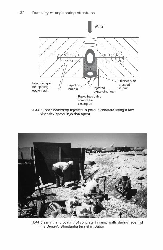
132 Durability of engineering structures
Rubber pipepressedin joint
Injectionneedle
Rapid-hardeningcement forclosing off
Injectedexpanding foam
Injection pipefor injectingepoxy resin
Water
3.43 Rubber waterstop injected in porous concrete using a lowviscosity epoxy injection agent.
3.44 Cleaning and coating of concrete in ramp walls during repair ofthe Deira-Al Shindagha tunnel in Dubai.

shows the cleaning and coating operation of concrete walls in the ramps.
5 Replacing the removed concrete (Principle 7, Method 7.2). Initially,a polymer-modified shotcrete with blast furnace slag cement CEM III/B as the cementitious binder was applied (called SPCC, see Section3.6.3). Later on, the polymer was replaced by silica fume for operationalreasons.
6 The reinforcement cover was extended by 20mm (Principle 7, Method7.1) with the same shotcrete.
7 An airtight coating was applied limiting oxygen flow to the reinforce-ment (Principle 9, Method 9.1). An oxygen-diffusion resistance of thecoating system of 4000m was required. In general, cutting off oxygeningress in concrete is difficult to achieve in repair works. In the actualcase of the submerged tunnel, it was, however, considered feasible iftaken in conjunction with other measures.
The coating system consisted of two epoxy coatings and apolyurethane topcoat.The topcoat showed better resistance to UV radi-ation, which was a specific requirement for the tunnel ramps, and alsohad a crack-bridging ability. Prior to applying the coating, the surfacewas smoothed with an epoxy-based equalization slurry.
Repair using cathodic protection had also been considered. There were,however, two reasons for rejecting this method. In the first place, experi-ence with cathodic protection systems in concrete structures was limited inthe 1980s. In addition, electro-continuity of the reinforcement was difficultto achieve. Rebars were placed in an irregular fashion and sometimes evenabsent.
3.10.1.4 Execution of the works
The repairs started with a trial repair, which led to modifications in the spec-ifications. An extensive survey of the concrete was made, including crackmapping and chloride profiles. Repairs started in 1986 and were completedin 1988. During the whole operation, repairs were guided by calculationson the structural safety of the sections where concrete was removed andwhere rebars were replaced. Quality control was very strict and regardedas essential to repair work success.
Part of the contract consisted in drafting a maintenance manual for thetunnel and it was regarded essential to maintain the tunnel according tostrict rules. Obviously, not all affected areas could be repaired due to struc-tural reasons and renewed cracking in these areas could not be excluded.A thorough inspection regime would therefore take immediate action ifdefects were observed so as to avoid progressive deterioration. In 2002
Concrete 133

when this book was drafted, the tunnel appeared to be in excellent condi-tion. No major repairs have been necessary since the completion of thetunnel wall repairs in 1988.
3.10.2 Cathodic protection repairs in multi-storey buildingson the Dutch coast
3.10.2.1 Case description
Balcony slabs of two multi-storey buildings in Zantvoort, a holiday resortin the Netherlands along the North Sea coast close to Amsterdam, showedsevere cracking due to chloride-initiated corrosion. The edges of thebalcony slabs were affected in particular. This was not only due to the pro-truding position of the edge rims, but also to the presence of a water-holeat the ceiling of the balcony slab. Reinforcement adjacent to this water-holeonly had a cover of about 15mm (see sketch in Fig. 3.45). The buildingswere erected in the 1970s. In one of the buildings prefabricated slabs wereapplied. The slabs of the other buildings were cast on site. The specifiedcover was 25mm and the slabs were produced from a Portland cement con-crete. In the past, local repairs had been carried out several times, butappeared to have failed. It was observed that adjacent to the epoxy repairmortars, the initial concrete showed cracks and the reinforcement was oftenseriously affected (see Fig. 3.46). This was probably due to the fact that therepaired area had access to oxygen and functioned as a cathodic area (incipient anode effect, see Section 3.5.3). Rebars that had been coated inprevious repair work showed renewed corrosion.
3.10.2.2 Measurements
Chloride profiles were determined on several occasions. They showed thatthe chloride content at the reinforcement had exceeded the critical corro-
134 Durability of engineering structures
Cover
3.45 Water-hole in balcony slab ceiling causing locally reducedreinforcement cover.
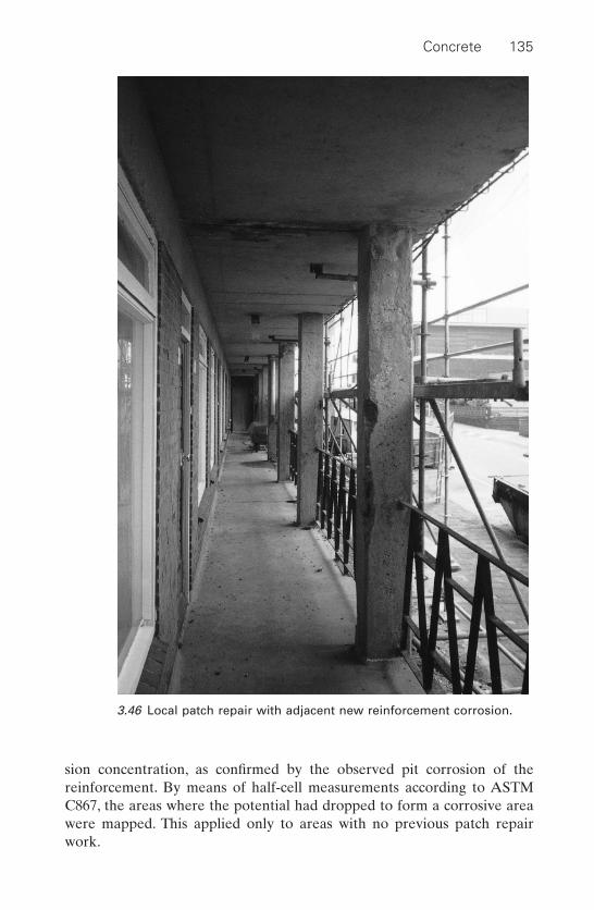
Concrete 135
3.46 Local patch repair with adjacent new reinforcement corrosion.
sion concentration, as confirmed by the observed pit corrosion of the reinforcement. By means of half-cell measurements according to ASTMC867, the areas where the potential had dropped to form a corrosive areawere mapped. This applied only to areas with no previous patch repairwork.
3.10.2.3 Conventional repair or cathodic protection?
The tendering contractors were requested to table two proposals. One fora ‘conventional repair’ consisting of removing all concrete at the rein-forcement that was contaminated beyond the critical level, cleaning of thereinforcement etc, and an alternative proposal using cathodic protection.The owner chose the cathodic protection proposal because:
1 The contractor to whom the contract was awarded was able to provethat the life time cost of cathodic protection repairs was lower than thatof the conventional repair system, even though the initial repair cost washigher. In particular, the maintenance cost of the conventional repairsystem, including expected recurring small repairs, was estimated to behigher.
2 Cathodic protection causes less trouble to building users during repairwork execution because noisy and dusty concrete removal could beavoided.
3 The owner had had a bad experience with the previous local patchrepairs in which the principles applied were similar to the conventionalrepair work on offer.
3.10.2.4 Method applied
All cracked concrete was removed and the reinforcement cleaned up orreplaced, as shown in Fig. 3.47. Most of the concrete on the edge rim wasremoved and the lower reinforcement, which was severely affected, wasreplaced. New concrete was cast. Connecting the reinforcement to safe-guard electro-continuity turned out to be a substantial job. The rebars of the upper reinforcement of the edge rim had, for instance, been cut frequently due to coring of concrete to fix the balcony rail.
Cables for connecting the DC current were attached to the reinforcementand silver/silver chloride reference cells were fixed near the reinforcement.Locally removed concrete was replaced with a cement grout by hand trow-elling.The ceiling of the balcony slab was grit-blasted. Subsequently, currentdissipator wires were pinned to the ceiling surface of the slabs and beams.The wires were titanium-based with a mixed rare metal oxides coat. A con-ducting acrylic coating filled with carbon particles and small copper fibreswas applied. The cables were connected to a rectifier supplying 1–2V DC.The applied potential and current were adjusted regularly during the firstmonth. A minimum 100mV instant off potential shift over a 24 hour periodwas applied as the cathodic protection criterion. Finally, a topcoat wasapplied.
136 Durability of engineering structures
3.11 References
1 Bijen J, Maintenance and Repair of Concrete Structures, Delft, Heron, Delft University of Technology, 1989 34 2.
2 Durability and Maintenance of Concrete Structures, CUR Report 172 (in Dutch),Gouda, CUR, 1994.
3 Pomeroy R D, The problem of hydrogen sulphide in sewers, Cheshar, Bucks, ClayPipe Development Association, 1977.
4 Bijen J, ‘Material aspects of manure silos (materiaalkundige aspecten mest-bassins)’, (in Dutch), Materialen 1988 9 32–9.
5 Durability of concrete foundations in greenhouses (duurzaamheid van betonnenpoeren in tuinbouwkassen), CUR Recommendation 8 (in Dutch), Gouda,1985.
6 Heinz D, Damaging Formation of Ettringite-like Phases in Heat-treated Mortars and Concrete (Schädigende Bildung ettrigitähnliche-Phasen in wärme-behandelter Mörteln und Beton), Dissertation RWTH, Aachen, Germany, 1986.
7 Measures to prevent damage due to alkali-silica reaction, CUR Recommendation89 (in Dutch), Gouda, 2002.
8 Stark J, Ludwig H M, ‘Freeze De-icing Salt Resistance of Concretes ContainingBlast Furnace Slag Cement,’ in Freeze Thaw Durability of Concrete, (ed) SakaiK et al. London, E & F N Spon, 1997.
9 Chemical Admixtures for Concrete, ACI manual of Concrete Practice, Part 1:Materials and General Properties of Concrete, Detroit, ACI 212.3R-91, 1994.
10 Carbonation, Corrosion and Moisture, CUR Report 90–3 (in Dutch), Gouda,1990.
11 Meijers S, Computational Modeling of Chloride Ion Ingress in Reinforced Con-crete, Delft, Dissertation, Delft University of Technology, 2003.
Concrete 137
3.47 Removed concrete and replaced reinforcement at the edge of abalcony slab.
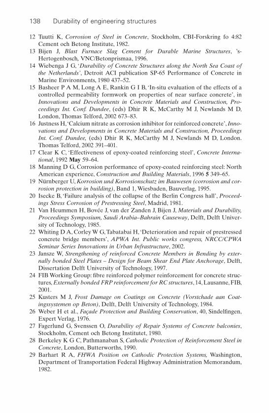
12 Tuutti K, Corrosion of Steel in Concrete, Stockholm, CBI-Forskring fo 4:82Cement och Betong Institute, 1982.
13 Bijen J, Blast Furnace Slag Cement for Durable Marine Structures, ’s-Hertogenbosch, VNC/Betonprismaa, 1996.
14 Wiebenga J G, ‘Durability of Concrete Structures along the North Sea Coast ofthe Netherlands’, Detroit ACI publication SP-65 Performance of Concrete inMarine Environments, 1980 437–52.
15 Basheer P A M, Long A E, Rankin G I B, ‘In-situ evaluation of the effects of acontrolled permeability formwork on properties of near surface concrete’, inInnovations and Developments in Concrete Materials and Construction, Pro-ceedings Int. Conf. Dundee, (eds) Dhir R K, McCarthy M J, Newlands M D,London, Thomas Telford, 2002 673–83.
16 Justness H, ‘Calcium nitrate as corrosion inhibitor for reinforced concrete’, Inno-vations and Developments in Concrete Materials and Construction, ProceedingsInt. Conf. Dundee, (eds) Dhir R K, McCarthy M J, Newlands M D, London.Thomas Telford, 2002 391–401.
17 Clear K C, ‘Effectiveness of epoxy-coated reinforcing steel’, Concrete Interna-tional, 1992 May 59–64.
18 Manning D G, Corrosion performance of epoxy-coated reinforcing steel: NorthAmerican experience, Construction and Building Materials, 1996 5 349–65.
19 Nürnberger U, Korrosion und Korrosionschutz im Bauwesen (corrosion and cor-rosion protection in building), Band 1, Wiesbaden, Bauverlag, 1995.
20 Isecke B, ‘Failure analysis of the collapse of the Berlin Congress hall’, Proceed-ings Stress Corrosion of Prestressing Steel, Madrid, 1981.
21 Van Heummen H, Bovée J, van der Zanden J, Bijen J, Materials and Durability,Proceedings Symposium, Saudi Arabia–Bahrain Causeway, Delft, Delft Univer-sity of Technology, 1985.
22 Whiting D A, Corley W G, Tabatabai H, ‘Deterioration and repair of prestressedconcrete bridge members’, APWA Int. Public works congress, NRCC/CPWASeminar Series Innovations in Urban Infrastructure, 2002.
23 Jansze W, Strengthening of reinforced Concrete Members in Bending by exter-nally bonded Steel Plates – Design for Beam Shear End Plate Anchorage, Delft,Dissertation Delft University of Technology, 1997.
24 FIB Working Group: fibre reinforced polymer reinforcement for concrete struc-tures, Externally bonded FRP reinforcement for RC structures, 14, Lausanne, FIB,2001.
25 Kusters M J, Frost Damage on Coatings on Concrete (Vorstchade aan Coat-ingssystemen op Beton), Delft, Delft University of Technology, 1984.
26 Weber H et al., Façade Protection and Building Conservation, 40, Sindelfingen,Expert Verlag, 1976.
27 Fagerlund G, Svenssen O, Durability of Repair Systems of Concrete balconies,Stockholm, Cement och Betong Institutet, 1980.
28 Berkeley K G C, Pathmanaban S, Cathodic Protection of Reinforcement Steel inConcrete, London, Butterworths, 1990.
29 Barhart R A, FHWA Position on Cathodic Protection Systems, Washington,Department of Transportation Federal Highway Administration Memorandum,1982.
138 Durability of engineering structures
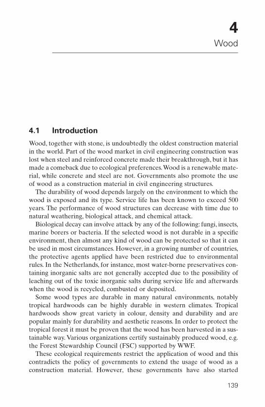
4Wood
4.1 Introduction
Wood, together with stone, is undoubtedly the oldest construction materialin the world. Part of the wood market in civil engineering construction waslost when steel and reinforced concrete made their breakthrough, but it hasmade a comeback due to ecological preferences.Wood is a renewable mate-rial, while concrete and steel are not. Governments also promote the useof wood as a construction material in civil engineering structures.
The durability of wood depends largely on the environment to which thewood is exposed and its type. Service life has been known to exceed 500years. The performance of wood structures can decrease with time due tonatural weathering, biological attack, and chemical attack.
Biological decay can involve attack by any of the following: fungi, insects,marine borers or bacteria. If the selected wood is not durable in a specificenvironment, then almost any kind of wood can be protected so that it canbe used in most circumstances. However, in a growing number of countries,the protective agents applied have been restricted due to environmentalrules. In the Netherlands, for instance, most water-borne preservatives con-taining inorganic salts are not generally accepted due to the possibility ofleaching out of the toxic inorganic salts during service life and afterwardswhen the wood is recycled, combusted or deposited.
Some wood types are durable in many natural environments, notablytropical hardwoods can be highly durable in western climates. Tropicalhardwoods show great variety in colour, density and durability and arepopular mainly for durability and aesthetic reasons. In order to protect thetropical forest it must be proven that the wood has been harvested in a sus-tainable way. Various organizations certify sustainably produced wood, e.g.the Forest Stewardship Council (FSC) supported by WWF.
These ecological requirements restrict the application of wood and thiscontradicts the policy of governments to extend the usage of wood as a construction material. However, these governments have also started
139

developing new processes to protect wood without the environmental draw-backs of the old methods, especially for wood from the temperate climate zone.
In this chapter, the following topics will be discussed:
• Deterioration mechanisms.• Protection of wood.• Hazard classes.• Durability classes.• Maintenance.• Repair of affected structures.
The terminology used is that of the European standards for wood.
4.2 Deterioration
4.2.1 Decay by fungi
4.2.1.1 Mechanisms
Fungi (French: moisi, German: Pilze, Dutch: schimmels) cause decay ofwood.1 They pose the most serious threat to wooden structures that are notsubmerged in water.The life cycle of fungi is shown in Fig. 4.1.2 The hyphae,fine tubes, grow into a dense network called a mycelium that affects thewood.The hyphae produce enzymes that disintegrate the cellulose or lignin,
140 Durability of engineering structures
Fungus Life cycle of fungi Hyphae
Spores
Mycelium
4.1 Life cycle of fungi.2
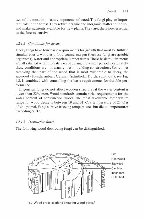
two of the most important components of wood. The fungi play an impor-tant role in the forest. They return organic and inorganic matter to the soiland make nutrients available for new plants. They are, therefore, essentialto the forests’ survival.
4.2.1.2 Conditions for decay
Decay fungi have four basic requirements for growth that must be fulfilledsimultaneously: wood as a food source, oxygen (because fungi are aerobicorganisms), water and appropriate temperatures. These basic requirementsare all satisfied within forests, except during the winter period. Fortunately,these conditions are not usually met in building constructions. Sometimesremoving that part of the wood that is most vulnerable to decay, thesapwood (French: aubier, German: Splintholz, Dutch: spinthout), see Fig.4.2, is combined with controlling the basic requirements for durable per-formance.
In general, fungi do not affect wooden structures if the water content islower than 22% m/m. Wood standards contain strict requirements for thewater content of construction wood. The most favourable temperaturerange for wood decay is between 19 and 31°C; a temperature of 25°C isoften optimal. Fungi survive freezing temperatures but die at temperaturesexceeding 60°C.
4.2.1.3 Destructive fungi
The following wood-destroying fungi can be distinguished:
Wood 141
Pith
Heartwood
Sapwood
Cambium
Inner bark
Outer bark
4.2 Wood cross-sections showing wood parts.3
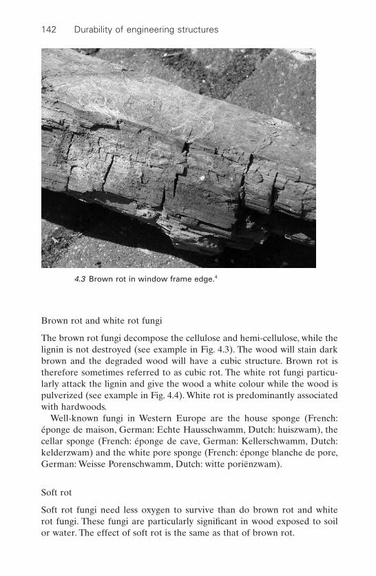
Brown rot and white rot fungi
The brown rot fungi decompose the cellulose and hemi-cellulose, while thelignin is not destroyed (see example in Fig. 4.3). The wood will stain darkbrown and the degraded wood will have a cubic structure. Brown rot istherefore sometimes referred to as cubic rot. The white rot fungi particu-larly attack the lignin and give the wood a white colour while the wood ispulverized (see example in Fig. 4.4). White rot is predominantly associatedwith hardwoods.
Well-known fungi in Western Europe are the house sponge (French:éponge de maison, German: Echte Hausschwamm, Dutch: huiszwam), thecellar sponge (French: éponge de cave, German: Kellerschwamm, Dutch:kelderzwam) and the white pore sponge (French: éponge blanche de pore,German: Weisse Porenschwamm, Dutch: witte poriënzwam).
Soft rot
Soft rot fungi need less oxygen to survive than do brown rot and white rot fungi. These fungi are particularly significant in wood exposed to soil or water. The effect of soft rot is the same as that of brown rot.
142 Durability of engineering structures
4.3 Brown rot in window frame edge.4
Wood-disfiguring fungi
The most important are the fungi causing mould or blue stain. These fungiare not a structural threat but do affect the aesthetic appearance. They cangrow through decorative coatings and degrade them.
Moulds are not specific to wood and can grow on any material with ahigh moisture content.
4.2.2 Degradation by insects
This can involve attack by beetles, termites and ants.
Beetles
The wood-affecting beetles are insects capable of flying that lay their eggsin wood pores or cracks and have larvae that attack the wood.The life cycleof wood-boring beetles is shown in Fig. 4.5. They are present throughoutEurope. Only those beetles that affect seasoned (dried) wood will be dis-cussed. The most important ones are: the Death Watch beetle (Xestobium
Wood 143
4.4 White rot predominantly affecting lignin.5
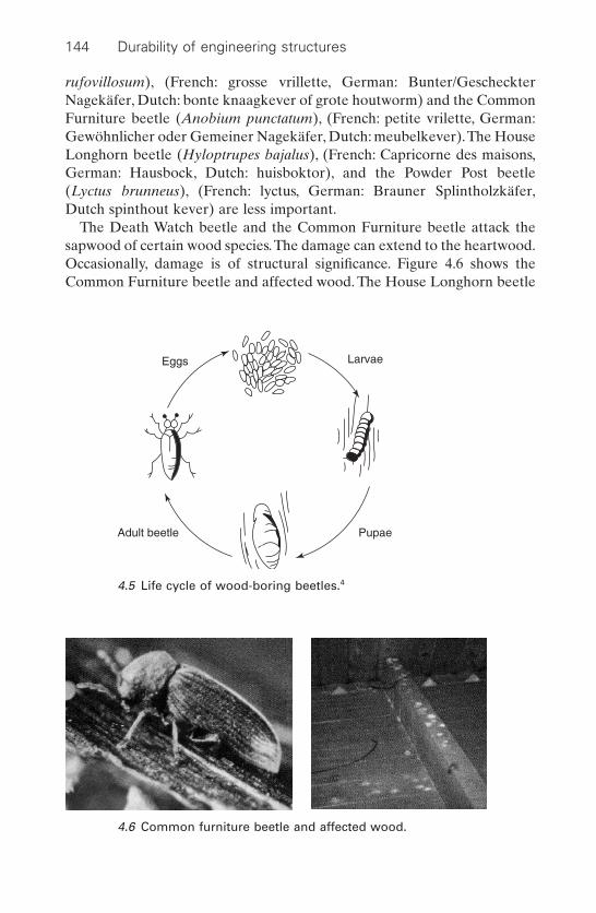
rufovillosum), (French: grosse vrillette, German: Bunter/GescheckterNagekäfer, Dutch: bonte knaagkever of grote houtworm) and the CommonFurniture beetle (Anobium punctatum), (French: petite vrilette, German:Gewöhnlicher oder Gemeiner Nagekäfer, Dutch: meubelkever).The HouseLonghorn beetle (Hyloptrupes bajalus), (French: Capricorne des maisons,German: Hausbock, Dutch: huisboktor), and the Powder Post beetle(Lyctus brunneus), (French: lyctus, German: Brauner Splintholzkäfer,Dutch spinthout kever) are less important.
The Death Watch beetle and the Common Furniture beetle attack thesapwood of certain wood species.The damage can extend to the heartwood.Occasionally, damage is of structural significance. Figure 4.6 shows theCommon Furniture beetle and affected wood. The House Longhorn beetle
144 Durability of engineering structures
4.6 Common furniture beetle and affected wood.
Eggs
Adult beetle Pupae
Larvae
4.5 Life cycle of wood-boring beetles.4

is found throughout Europe, but less so in the north and north-west. Itattacks mainly softwood species. The Powder Post beetle primarily attacksthe sapwood of hardwoods, such as oak, ash and walnut. Powder Postbeetles are usually discovered when small piles of fine bore dust areobserved on or below the surface.The name ‘powder post’ refers to the phe-nomenon that, in heavily damaged wood, the sapwood is reduced to a massof powdered wood held in place by a thin outer wood surface.
Termites
Termites (Isoptera or white ants) do by far the greatest amount of insect-related damage to wood. They have been confined to tropical and near-tropical areas but probably due to climatic changes, they are spreadingnorthwards. In Europe, termites have been observed in Paris, Hamburg andthe UK.
There are thousands of species of termites, but in Europe only four species are found. Most dangerous for buildings are the subterraneanspecies, principally Reticuliterms lucifugus and Reticulitermes santonensis.Termites live in colonies; because of their large concentrations, damage pro-ceeds quickly as soon as buildings become infested. Wood damaged by sub-terranean termites may show few, if any, signs of deterioration. Bypounding, hollow infested areas can be detected and when broken up, thelive termites are discovered.
4.2.3 Attack by marine borers
With the exception of a few resistant tropical woods, any untreated woodput to use or stored in salt or brackish water, throughout most of the world,is subject to damage by marine borers.The speed with which damage occursdepends upon climate, pollution, borer species, and other factors. Damageoccurs most rapidly in warmer climates.
The most important marine borers with respect to wood damage are mol-luscan borers called shipworms (Banksia spp. and Teredo spp.) (French:taret, German: Schiffsbauwurm, Dutch: paalworm) and crustacean borerscalled gribble (Limnori). They use wood for food as well as for shelter.Shipworms are the most destructive. The immature forms enter the woodthrough pinhole-sized openings that never increase in size. The shipwormsexcavate tunnels; eventually they may honeycomb the interior of infestedwood with little exterior evidence of attack. The ant-sized gribbles extendtheir small tunnels into the outer few centimetres of the wood. The surfaceof infested wood becomes sponge-like in appearance and erodes away, par-ticularly at the waterline.
Wood 145

4.2.4 Bacterial attack
Bacteria degrade all wood in almost all environments. However, theirenzyme production is slow and they therefore cause relatively little damage in comparison with other degraders. Bacteria are able to degradepreserved wood or highly durable species in conditions of low oxygen concentrations.
Bacteria mainly attack cellulose. Because the cellulose and hemi-cellulose are protected by lignin, this kind of attack is usually restricted.Where soft rot can cause deterioration within months, bacterial attackshows significant damage only after many years. Nevertheless, in theNetherlands where many houses and buildings are built on wooden foun-dation piles, serious problems have arisen with slowly deteriorating woodenpiles under ground water level due to bacterial attack. The bacteria canfunction even under conditions of little aeration. A minor drain of oxygenfrom the top of the pile, which is beyond the water table, can suffice. Scotchfir (Pinus sylvestris) piles, also called Scots pine (French: sapin ecossaise,German: Scottische Tanne, Dutch: grenen) appears to be more sensitive tothis attack than are other softwoods. However, knowledge of this type ofdeterioration is restricted.
4.2.5 Weathering
Natural outdoor weathering occurs due to combined exposure to sunlightand moisture. The absorption of UV radiation from the sun causes degra-dation of the lignin, which can subsequently be washed out by water. Asilver-grey surface remains primarily consisting of cellulose components.Changes in moisture content, especially when exposed to rain, cause mois-ture gradients and consequently stresses in the wood that can aggravate theprocess. The completely weathered grey layer is only a few tenths of mil-limetres thick and, within two millimetres from the surface, the wood is notaffected any more. The effect of weathering on strength properties is verylimited. Surface abrasion resistance is reduced and toughness is somewhatdiminished in a continuous process. This means that weathering as such isnot a threat to structural applications. However, if the moisture content inuse exceeds 20% of decay and degradation by insects, this will endangerwood durability, as discussed above.
4.2.6 Chemical attack
In general, wood shows good resistance to a variety of chemicals. Its resis-tance to acids is superior in comparison with that of steel and concrete. Itis therefore used for tanks and other containers. Strong acids and strongalkaline solutions do, however, deteriorate wood.
146 Durability of engineering structures
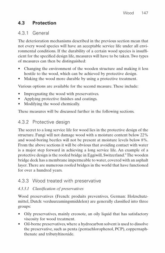
4.3 Protection
4.3.1 General
The deterioration mechanisms described in the previous section mean thatnot every wood species will have an acceptable service life under all envi-ronmental conditions. If the durability of a certain wood species is insuffi-cient for the specified design life, measures will have to be taken. Two typesof measures can then be distinguished:
• Changing the environment of the wooden structure and making it lesshostile to the wood, which can be achieved by protective design.
• Making the wood more durable by using a protective treatment.
Various options are available for the second measure. These include:
• Impregnating the wood with preservatives.• Applying protective finishes and coatings.• Modifying the wood chemically.
These measures will be discussed further in the following sections.
4.3.2 Protective design
The secret to a long service life for wood lies in the protective design of thestructure. Fungi will not damage wood with a moisture content below 22%and wood-boring beetles will not be present at moisture levels below 8%.From the above sections it will be obvious that avoiding contact with wateris a major step forward in achieving a long service life. An example of aprotective design is the roofed bridge in Eggiwill, Switzerland.6 The woodenbridge deck has a membrane impermeable to water, covered with an asphaltlayer. There are numerous roofed bridges in the world that have functionedfor over a hundred years.
4.3.3 Wood treated with preservative
4.3.3.1 Classification of preservatives
Wood preservatives (French: produits preventives, German: Holzschutz-mittel, Dutch: verduurzamingsmiddelen) are generally classified into threegroups:
• Oily preservatives, mainly creosote, an oily liquid that has satisfactoryviscosity for wood treatment.
• Oil-borne preservatives, where a hydrocarbon solvent is used to dissolvethe preservative, such as penta (pentachlorophenol, PCP), coppernaph-thenate and tributyltinoxide.
Wood 147
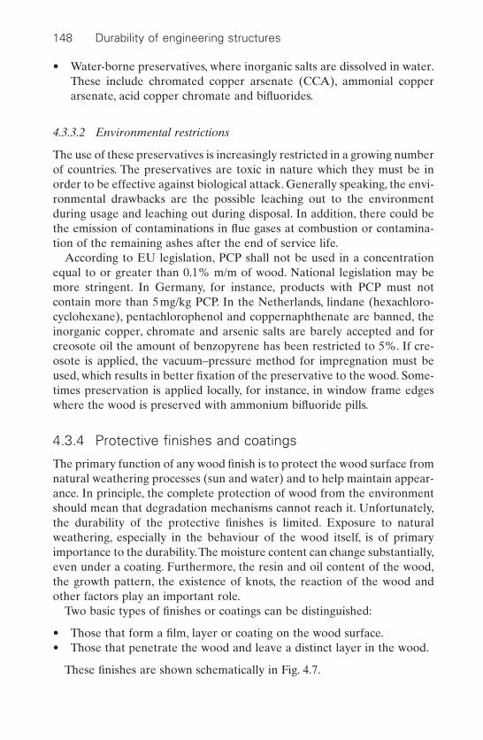
• Water-borne preservatives, where inorganic salts are dissolved in water.These include chromated copper arsenate (CCA), ammonial copperarsenate, acid copper chromate and bifluorides.
4.3.3.2 Environmental restrictions
The use of these preservatives is increasingly restricted in a growing numberof countries. The preservatives are toxic in nature which they must be inorder to be effective against biological attack. Generally speaking, the envi-ronmental drawbacks are the possible leaching out to the environmentduring usage and leaching out during disposal. In addition, there could bethe emission of contaminations in flue gases at combustion or contamina-tion of the remaining ashes after the end of service life.
According to EU legislation, PCP shall not be used in a concentrationequal to or greater than 0.1% m/m of wood. National legislation may bemore stringent. In Germany, for instance, products with PCP must notcontain more than 5mg/kg PCP. In the Netherlands, lindane (hexachloro-cyclohexane), pentachlorophenol and coppernaphthenate are banned, theinorganic copper, chromate and arsenic salts are barely accepted and forcreosote oil the amount of benzopyrene has been restricted to 5%. If cre-osote is applied, the vacuum–pressure method for impregnation must beused, which results in better fixation of the preservative to the wood. Some-times preservation is applied locally, for instance, in window frame edgeswhere the wood is preserved with ammonium bifluoride pills.
4.3.4 Protective finishes and coatings
The primary function of any wood finish is to protect the wood surface fromnatural weathering processes (sun and water) and to help maintain appear-ance. In principle, the complete protection of wood from the environmentshould mean that degradation mechanisms cannot reach it. Unfortunately,the durability of the protective finishes is limited. Exposure to naturalweathering, especially in the behaviour of the wood itself, is of primaryimportance to the durability.The moisture content can change substantially,even under a coating. Furthermore, the resin and oil content of the wood,the growth pattern, the existence of knots, the reaction of the wood andother factors play an important role.
Two basic types of finishes or coatings can be distinguished:
• Those that form a film, layer or coating on the wood surface.• Those that penetrate the wood and leave a distinct layer in the wood.
These finishes are shown schematically in Fig. 4.7.
148 Durability of engineering structures

4.3.4.1 Film-forming finishes
Within the family of film-forming finishes, a distinction can be madebetween paints and varnishes, on the one hand, and lacquers, on the other.The essential difference between these two classes is that the first class con-tains pigments that will eliminate UV degradation by sunlight.
Paints are commonly divided into oil-based or solvent-borne systems andlatex or water-borne systems. Latex paints are used more frequently thanoil-based paints for finishing wood, particularly for exterior use. Because ofoccupational health concerns, the usage of solvent-borne paints is notallowed for the interior of dwellings in a number of countries. Paint is,however, not a preservative; it will not prevent decay if conditions arefavourable to fungal growth. Clear varnishes or lacquers (French: laque ouvernis, Germann: Lack oder Firnis, Dutch: vernis of lak) give wood anattractive initial appearance. Other treatments either change the colour ofthe wood or cover it completely. Unfortunately, varnish finishes used onwood exposed to sun and rain require frequent maintenance so as to retain a satisfactory appearance. The addition of colourless UV lightabsorbers to clear finishes has had only moderate success in aiding reten-tion of natural colour and original surface structure. It is generally acceptedthat opaque pigments found in paints and stains provide the most effectiveand long-lasting protection against light. Eventually, the varnish will flake and crack off, taking with it wood fibres that have been degraded photochemically.
Wood 149
woodCoating
Varnish or lacquer
Penetrating waterrepellent
wood
wood
4.7 Wood protection finishes.2

4.3.4.2 Penetrating finishes
Penetrating water repellents (French: brou, German: Beize, Dutch: beits)reduce absorption of water and decrease the moisture content of the wood. The result is that the wood becomes more resistant to biologicalattack.Where pigments are added to the water-repellent products the woodis stained, while still permitting much of the wood grain to show through.Oily and oil-borne preservatives also have water-repellent properties. Partof the enhanced resistance of wood treated with these agents is due to thiseffect.
4.3.5 Wood modification
A distinction can be made between treatments where the pores are filledup and those where the wall cell is modified. The wall cells can be changedby chemical and thermal modification.
The wood microstructure is depicted in Fig. 4.8.Where the pores are filledup the wood is penetrated with a resin that fills up the lumina. Sometimes,the cell wall cavities can also be partly filled. In modified wood systems, thechemistry of the cell wall is changed. The most abundant functional groupin wood is the hydroxyl group. The hydrophilic nature of this group is themain cause of the moisture-sensitive behaviour of wood, as shown in Fig.4.9. In the modified wood treatment, the hydroxyl groups are substitutedby hydrophobic groups or are cross-linked, as shown in Fig. 4.10.
Chemical modification treatments, such as acetylation, esterification,etherification, treatments with urethane, oxidation and silanization of wood,look very promising. Most widely applied are acetylation and esterification.Figure 4.11 shows wood leaving an acetylating tank. The most developedcross-linking processes are thermal and hydrothermal treatments. Woodmodification processes upgrade most woods so they become highly
150 Durability of engineering structures
Cell lumen
Cell wall
4.8 Wood structure and distribution of chemical components withinthe cell wall.7
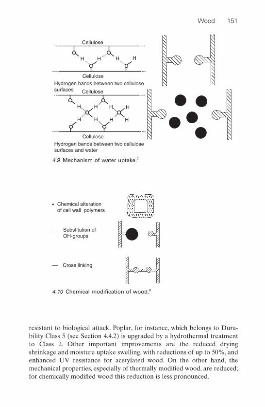
resistant to biological attack. Poplar, for instance, which belongs to Dura-bility Class 5 (see Section 4.4.2) is upgraded by a hydrothermal treatmentto Class 2. Other important improvements are the reduced drying shrinkage and moisture uptake swelling, with reductions of up to 50%, andenhanced UV resistance for acetylated wood. On the other hand, themechanical properties, especially of thermally modified wood, are reduced;for chemically modified wood this reduction is less pronounced.
Wood 151
H H H H
Cellulose
CelluloseHydrogen bands between two cellulosesurfaces
H
H H H
H
H
H H
Cellulose
CelluloseHydrogen bands between two cellulosesurfaces and water
4.9 Mechanism of water uptake.7
Cross linking
Substitution ofOH-groups
Chemical alterationof cell wall polymers
4.10 Chemical modification of wood.8

4.4 Hazard and durability classes
4.4.1 Hazard classes
The European standard EN 335 Durability of wood and wood-based prod-ucts – Definition of hazard classes of biological attack identifies the hazardclass (French: classe de risque, German: Gefährdungsklasse, Dutch: risi-coklasse) of a given service environment and geographical location.
The definition of the hazard classes is given in Table 4.1.
4.4.2 Durability classes
The European standard EN 350 Durability of wood and wood-based prod-ucts – natural durability of solid wood classifies natural durability in rela-tion to the various agencies of biological attack. There is a five-grade scalefor resistance to fungal attack (Table 4.2), a two-grade scale (susceptible
152 Durability of engineering structures
4.11 Wood leaving an acetylating tank, AKBV plant, Arnhem, theNetherlands, 1998.

Wood 153
Table 4.1 Hazard classes and occurrence of biological agencies according toEN 335-1
Hazard Exposure Biological attack Examples
class
1 Above ground, covered beetles, termitesa indoor applications, (dry) such as wooden frames
of houses covered by roofs and cladding.
2 Above ground, covered fungi, beetles, carports, window (risk of occasional termitesa frames, the roofed wetting) bridge discussed in
Section 4.3.23 Above ground, not fungi, beetles, bridge beams and
covered (risk of termitesa decks, sheds, cladding frequent wetting) of buildings without
protection4 In contact with soil or fungi, beetles, fences, piers, sheet pile
fresh water termitesa, walls, sluice doors(permanently) bacteria
5 In salt water fungi, beetles, mooring posts, piers, (permanently) termites,a breakwaters, sea-
marine borers defence walls
a termites are only present locally in Southern Europe
Table 4.2 Classes of natural durability of wood exposed to fungal attackaccording to EN 350 and examples of wood species
Durability Description Examples
class
1 Highly durable teak, azobe, iroko, jarrah, bilinga2 Durable Balau/bangkirai, karri, merbau, western red
cedar, European oak (French: chêne rouvre,German: Eiche, Dutch eik), robinia (French:robinet faux acacia, German: Robinie, Dutch:robinia)
3 Moderately red merati, Douglas firdurable
4 Slightly durable Norway spruce (French: epicea, German: Fichte,Dutch: spar)
5 Not durable beech (French: hêtre, German: Buche, Dutch:beuk), ash (French: frêne, German: Esche, Dutch:es), poplar (French: peuplier, German: Pappel,Dutch: populier)

and durable) for resistance to dry wood-destroying beetles and a three-grade scale (susceptible, moderately durable and durable) for resistance totermites and marine borers. Determination of the classification of a woodspecies requires the performance of the wood in standardized tests. Ingeneral, sapwood is not durable. The examples of wood given in Table 4.2are all for heartwood.
4.4.3 Matching hazard class and durability class
For each application in a specific service environment and geographicallocation, wood of a specific minimum durability class must be chosen. Table4.3 offers guidance.
4.5 Maintenance and restoration
4.5.1 Preventive maintenance
If wood performance declines as expected according to the design of thestructure, but is still beyond an acceptable level, we can improve it so that the service life of the wooden product or structure is extended for another period, as described in Section 6.7. This is known as preventive
154 Durability of engineering structures
Table 4.3 Guidance in choosing wood of a specific durability class for a specifichazard class2
Hazard class Durability class
1 2 3 4 5
1 S S S S S2 S S S (S) (S)3 S S (P) (S)–(P)4 S (P) P P5 S P (P) P P
S : Natural durability sufficient(S) : Natural durability in principle sufficient, but under special service
conditions the wood must be preserved(S)–(P): Natural durability can be sufficient, but the choice of wood, the
treatability of the wood by preservatives and the application determinewhether or not the wood should be preserved
(P) : Treatment is applied, but under some service conditions, the naturaldurability can be sufficient
P : Treatment is required
maintenance. If the wood was unprotected it can be protected according to one of the methods presented in Section 4.3. If the skin of the wood is weathered, it should be removed before a protective finish or coating isapplied.
4.5.2 Curative restoration
When the observed decline in wood performance has not been foreseen,but performance is still beyond a critical level, as shown in Fig. 6.1, curativemeasures are required to stop deterioration. In the case of wood affectedby fungi or insects, destroying them should halt the erosion. This can bedone either by increasing the temperature, by ultrasonic treatment (beetlesonly) or by applying fumigants. Increasing the temperature beyond 60°Ckills fungi (not the spores) and beetles. This is not applicable to every struc-ture, but the remedy can usually be applied in houses.
Fumigants used to protect wood fall into two broad categories: those thatrapidly destroy the insects or fungi, but do not remain in the wood for long,and agents that will stay in the wood for many years. The latter will, ofcourse, retain their function, while in the former, new colonizing can occurunless other protective measures are taken. An example of a short-termfumigant is methyl bromide. All fumigants are toxic chemicals and are haz-ardous for human beings when misapplied. Long-term fumigants can evap-orate slowly and can endanger the indoor climate. In many countries theuse of these fumigants for curative wood restoration is banned or subjectto strict rules.
4.6 Repair
When a wooden structure is seriously decayed, it is best replaced. However,the wood is often only locally affected and replacement of the wholewooden building component could be cumbersome and expensive. Occa-sionally, when it concerns monuments, replacement is considered undesir-able because preservation of the cultural heritage must be considered.Instead there exists a well-known technique to remove the affected woodand replace it with a new, better decay-resistant wood and connect the oldand the new wood by gluing. However, for structural applications this isoften not safe enough. Frequently, reinforcement must be added tostrengthen the connections, which, as shown in Fig. 4.12,9 enhances the loadtransfer between the old and new wood. The reinforcement can consist ofcarbon rebars, stainless steel rebars or other such items.
Sometimes, the affected wood is not completely replaced, but repairs arecarried out using an epoxy mortar.Another possibility is to repair and apply
Wood 155
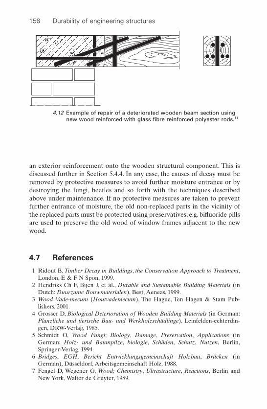
an exterior reinforcement onto the wooden structural component. This isdiscussed further in Section 5.4.4. In any case, the causes of decay must beremoved by protective measures to avoid further moisture entrance or bydestroying the fungi, beetles and so forth with the techniques describedabove under maintenance. If no protective measures are taken to preventfurther entrance of moisture, the old non-replaced parts in the vicinity ofthe replaced parts must be protected using preservatives; e.g. bifluoride pillsare used to preserve the old wood of window frames adjacent to the newwood.
4.7 References
1 Ridout B, Timber Decay in Buildings, the Conservation Approach to Treatment,London, E & F N Spon, 1999.
2 Hendriks Ch F, Bijen J, et al., Durable and Sustainable Building Materials (inDutch: Duurzame Bouwmaterialen), Best, Aeneas, 1999.
3 Wood Vade-mecum (Houtvademecum), The Hague, Ten Hagen & Stam Pub-lishers, 2001.
4 Grosser D, Biological Deterioration of Wooden Building Materials (in German:Planzliche und tierische Bau- und Werkholzschädlinge), Leinfelden-echterdin-gen, DRW-Verlag, 1985.
5 Schmidt O, Wood Fungi; Biology, Damage, Preservation, Applications (inGerman: Holz- und Baumpilze, biologie, Schäden, Schutz, Nutzen, Berlin,Springer-Verlag, 1994.
6 Bridges, EGH, Bericht Entwicklungsgemeinschaft Holzbau, Brücken (inGerman), Düsseldorf, Arbeitsgemeinschaft Holz, 1988.
7 Fengel D, Wegener G, Wood; Chemistry, Ultrastructure, Reactions, Berlin andNew York, Walter de Gruyter, 1989.
156 Durability of engineering structures
4.12 Example of repair of a deteriorated wooden beam section usingnew wood reinforced with glass fibre reinforced polyester rods.11

8 Homan W J, Chemical Modification of Wood, Wageningen, SHR TimberResearch, 1997.
9 Paul O, The Beta-method; Applicability and Development (in German: Das Beta-Verfahren Bewährung und Neuentwicklung), Bautenschutz & Bausanierung,1996, 12 17–22.
Wood 157
5New high-performance materials
5.1 Introduction
New materials for structural applications developed in other industrialsectors have been adopted in civil engineering practice, but in the con-struction industry itself there are also incentives to develop new materials.These incentives are:
• Failing durability of structures manufactured from traditional materials.Thus the US Federal Highway Administration estimates that nearly30% of all bridges are either structurally deficient or functionally obsolete.
• Improved sustainability. Higher-strength materials allow for a leanerstructural design with more durable materials resistant to various envi-ronments and with an extended service life, which generally decreasesthe environmental impact of building.
• Cost optimization over the entire life cycle (see Section 6.8). Thus low-maintenance structures are generally favoured because of the high costof maintenance, repair or replacements, especially in countries with highlabour costs.
Materials that perform better during the building process are more easilyapplied and are more resistant or have a higher strength than the tradi-tional materials discussed in the previous chapter. They are called high-performance materials.
For the construction industry, the following materials for structural appli-cations will be considered:
• High-performance concrete.• High-performance steel and other metals.• Fibre-reinforced polymers (FRP).
These materials will be discussed briefly in terms of their general proper-ties and their durability will be described in greater depth.
158
5.2 High-performance concrete
5.2.1 Introduction
Any concrete that satisfies certain criteria aimed to overcome limitationsof conventional concrete can be called high-performance concrete (HPC).This includes concrete that shows:
• A much improved resistance to environmental influences (durability inservice): high-durability concrete.
• A substantially increased structural capacity while maintaining ade-quate durability: high-strength concrete.
• A significantly reduced construction time, e.g. to permit rapid openingor reopening of roads to traffic, without compromising long-term ser-viceability: high early-strength concrete.
• The ability of the fresh concrete to flow easily to fill form work and encapsulate reinforcing bars through grout action only while maintaining homogeneity: self-compacting or self-consolidating concrete (SCC).
It is, therefore, not possible to provide a unique definition of HPC withoutconsidering the performance requirements of the intended use of the concrete.
A definition of high-strength concrete according to the US FederalHighway Administration is given in Table 5.1. According to this table, itappears that an increase in strength coincides with improved durabilityparameters. This relationship will only be valid within a range of composi-tions made with the same raw materials; for instance, a change in cementtype can cause a major change in the durability parameters, e.g. the chlo-ride penetration rate, without a major change in strength.
An important topic covered in this book is design for durability.Design for durability of concrete structures is discussed in Chapter 3. Asstated in Section 3.4.7, for natural weathering conditions, even for aggres-sive ones, highly durable concrete structures can be made that are essentially corrective-maintenance free (Section 6.7.4) for a very long time,with no other measures than a dense plain concrete, albeit with the application of cements or concretes with additions. An example is the con-crete used in the Eastern Scheldt barrier in the Netherlands that wasdesigned for a 200 year period with the cover to be replaced after 75 years2.This concrete can be regarded as a high-performance concrete although itis, in fact, a normal-strength concrete. Its strength class is C35/45 accordingto EN 206-1. High resistance against chloride penetration is realized byapplying a CEM III/B blast furnace slag cement according to EN 197-1 (seeSection 3.4.7). This discussion is restricted to the durability aspects of
New high-performance materials 159
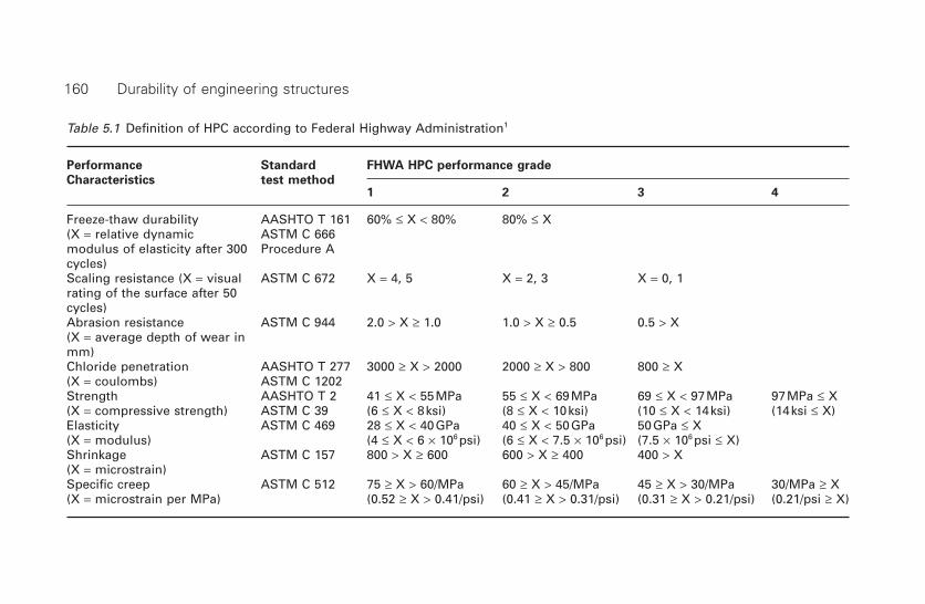
Table 5.1 Definition of HPC according to Federal Highway Administration1
Performance Standard FHWA HPC performance grade
Characteristics test method1 2 3 4
Freeze-thaw durability AASHTO T 161 60% £ X < 80% 80% £ X(X = relative dynamic ASTM C 666modulus of elasticity after 300 Procedure Acycles)Scaling resistance (X = visual ASTM C 672 X = 4, 5 X = 2, 3 X = 0, 1rating of the surface after 50cycles)Abrasion resistance ASTM C 944 2.0 > X ≥ 1.0 1.0 > X ≥ 0.5 0.5 > X(X = average depth of wear inmm)Chloride penetration AASHTO T 277 3000 ≥ X > 2000 2000 ≥ X > 800 800 ≥ X(X = coulombs) ASTM C 1202Strength AASHTO T 2 41 £ X < 55MPa 55 £ X < 69MPa 69 £ X < 97MPa 97MPa £ X(X = compressive strength) ASTM C 39 (6 £ X < 8ksi) (8 £ X < 10ksi) (10 £ X < 14ksi) (14ksi £ X)Elasticity ASTM C 469 28 £ X < 40GPa 40 £ X < 50GPa 50GPa £ X (X = modulus) (4 £ X < 6 ¥ 106 psi) (6 £ X < 7.5 ¥ 106 psi) (7.5 ¥ 106 psi £ X)Shrinkage ASTM C 157 800 > X ≥ 600 600 > X ≥ 400 400 > X(X = microstrain)Specific creep ASTM C 512 75 ≥ X > 60/MPa 60 ≥ X > 45/MPa 45 ≥ X > 30/MPa 30/MPa ≥ X(X = microstrain per MPa) (0.52 ≥ X > 0.41/psi) (0.41 ≥ X > 0.31/psi) (0.31 ≥ X > 0.21/psi) (0.21/psi ≥ X)
160 Durability of engineering structures
high-strength concrete, high early-strength concrete and self-compactingconcrete.
Since high strength and high durability can coincide, it is possible to usehigh-performance concrete for applications that normally are the exclusivedomain of steel. For instance, high-strength concrete is used in steel bridgedecks sensitive to fatigue corrosion in the Netherlands, as discussed inSection 2.3.2.12. The high-strength concrete dissipates the stresses due towheel loads. Another example is the intention of the Dutch Ministry ofTransport, Public Works and Water Management to develop a lift-bridge inhigh-strength reinforced concrete because it requires less maintenance thandoes a steel bridge.3
5.2.2 High-strength concrete
5.2.2.1 Composition and microstructure
High-strength concretes are obtained by the following measures:
• Low water/cement ratio (< 0.4).• Use of high-range water reducers, sometimes referred to as
superplasticizers.
The effect of these measures on the microstructure is a decrease in theaverage pore size, especially a decrease in the capillary pores (0.03–1 mm),and a more homogeneous cement paste. However, it has to be noticed thatnot every high-range water reducer has a positive effect. Mohammed et al.4
report that concrete with a polycarboxyl type of high-range water reducerhas shown relatively high ingress of chloride ions in test samples.
It is optional whether the following are applied:
• Highly reactive pozzolans, such as silica fume and metakaoline. Theirreactivity is partly due to their very fine nature (particles smaller thana few micrometres).
• Dense particle packing in the micron and sub-micron area.The very finereactive pozzolanic particles are able to fill up the open spaces betweencement particles, as shown in Fig. 5.1.
The effects of these applications are: a decrease in the average pore size, asubstantial decrease in the thickness of the porous interfacial zone aroundaggregates (see Fig. 5.2), a decrease of the free lime content (Ca(OH)2) andan increase of the CSH-gel of the concrete. The use of highly reactive poz-zolans, such as silica fume, decreases pore water alkalinity. The effects onthe microstructure and on the chemical composition in terms of durabilityare discussed in the following section.
New high-performance materials 161
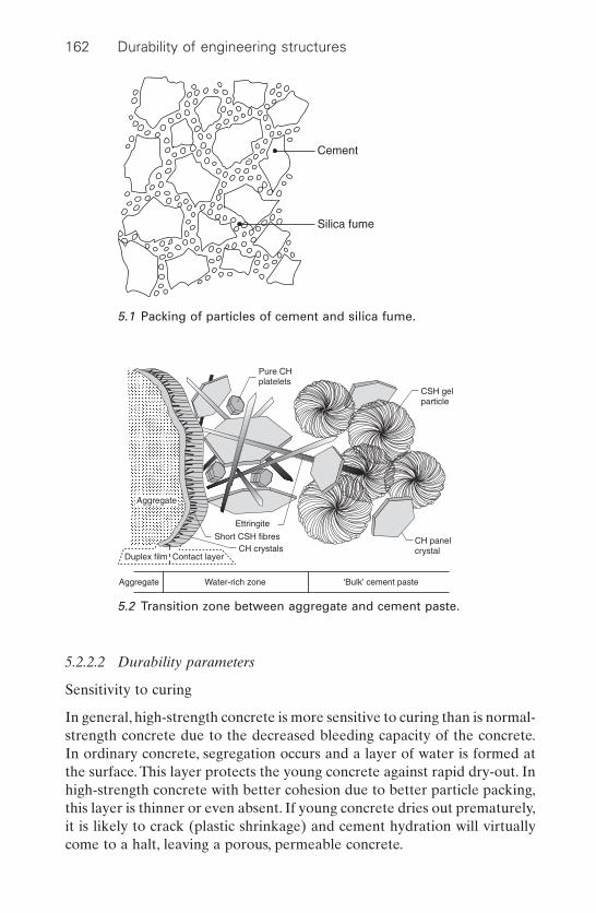
162 Durability of engineering structures
5.2.2.2 Durability parameters
Sensitivity to curing
In general, high-strength concrete is more sensitive to curing than is normal-strength concrete due to the decreased bleeding capacity of the concrete.In ordinary concrete, segregation occurs and a layer of water is formed atthe surface. This layer protects the young concrete against rapid dry-out. Inhigh-strength concrete with better cohesion due to better particle packing,this layer is thinner or even absent. If young concrete dries out prematurely,it is likely to crack (plastic shrinkage) and cement hydration will virtuallycome to a halt, leaving a porous, permeable concrete.
Pure CHplatelets
CSH gelparticle
Ettringite
Short CSH fibresCH crystals
CH panelcrystal
Duplex film Contact layer
Aggregate Water-rich zone ‘Bulk’ cement paste
Aggregate
5.2 Transition zone between aggregate and cement paste.
Cement
Silica fume
5.1 Packing of particles of cement and silica fume.

New high-performance materials 163
Autogeneous shrinkage
High-strength concrete shows a strong increase in autogeneous shrinkage,which can lead to cracking, especially when highly reactive pozzolans, suchas silica fume, are applied. This shrinkage is due to the decrease of solidmaterial volume during the reaction with water. It causes self-desiccationwith increased sensitivity to cracking. Cracks in concrete have a negativeeffect on the penetration rate, although in general the effect appears to besmall as long as the cracks are less than 0.3mm wide, as required in moststandards.
Chloride-initiated corrosion
An important parameter for the rate of chloride ingress is the chloride diffusion coefficient (see Section 3.4.3.1). The effect of decreasing the water/cement ratio on the resistance to chloride penetration is minor;possibly by a factor of 2 over the range of interest. However, reactive poz-zolans can have a much greater effect. Examples of the effect of variousmeasures to decrease the chloride diffusion coefficient are given in Table5.2.5 The use of highly reactive pozzolans, like silica fume, decreases porewater alkalinity, which in turn decreases the threshold chloride concentra-tion required for the onset of corrosion (see Section 3.4.5). Concurrently,the percentage of chloride bound to the cement can be diminished and con-sequently the free chloride concentration is increased. This effect is verynoticeable with silica fume. A positive effect of the changes in microstruc-ture is the increase in the electrical resistivity of concrete, as shown in Fig. 5.3.6
Frost–thaw de-icing salt resistance
In general, it can be stated that both the frost–thaw resistance and the de-icing salt scaling resistance increase at greater concrete strengths. However,results and conclusions are somewhat conflicting.7 Lack of correlationbetween existing laboratory performance tests and field experience makesa definite assessment difficult. Some researchers are of the opinion that airentrainment is not required for high-strength concrete, but others con-tradict this. In ordinary concrete, air-entrainment is used to enhance thefrost–thaw resistance (see Section 3.3.3). However, air entrainmentdecreases strength, which is in conflict with the aim of producing a high-strength concrete. If air-entrainment is applied, the required spacing factorappears to be smaller because of the reduced permeability of the concrete,which hinders water access to the air bubbles.
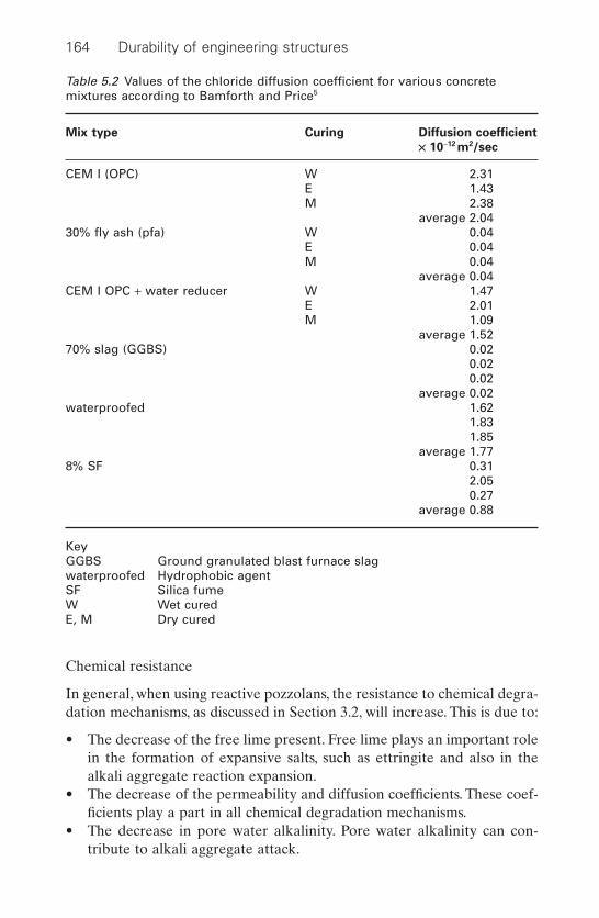
164 Durability of engineering structures
Chemical resistance
In general, when using reactive pozzolans, the resistance to chemical degra-dation mechanisms, as discussed in Section 3.2, will increase. This is due to:
• The decrease of the free lime present. Free lime plays an important rolein the formation of expansive salts, such as ettringite and also in thealkali aggregate reaction expansion.
• The decrease of the permeability and diffusion coefficients. These coef-ficients play a part in all chemical degradation mechanisms.
• The decrease in pore water alkalinity. Pore water alkalinity can con-tribute to alkali aggregate attack.
Table 5.2 Values of the chloride diffusion coefficient for various concretemixtures according to Bamforth and Price5
Mix type Curing Diffusion coefficient
¥ 10-12 m2/sec
CEM I (OPC) W 2.31E 1.43M 2.38
average 2.0430% fly ash (pfa) W 0.04
E 0.04M 0.04
average 0.04CEM I OPC + water reducer W 1.47
E 2.01M 1.09
average 1.5270% slag (GGBS) 0.02
0.020.02
average 0.02waterproofed 1.62
1.831.85
average 1.778% SF 0.31
2.050.27
average 0.88
KeyGGBS Ground granulated blast furnace slagwaterproofed Hydrophobic agentSF Silica fumeW Wet curedE, M Dry cured

New high-performance materials 165
• A reduction in the thickness of the water-rich, porous interfacial zone(see Fig. 5.2). This zone plays an important part in both expansive ettringite formation and alkali–silica expansion.
Abrasion–erosion resistance
High abrasion or erosion resistance can be required for various concretestructures in situations such as:
• Fast flowing water at dams that generate hydroelectricity.• Tidal movements along dams and bridge piers where abrasion occurs
by sand particles.• Drifting ice along concrete piles.• Pavements and bridge decks subject to studded tyres.
There appears to be a linear relationship between compressive strength andabrasion as shown in Fig. 5.4.8
0
20
40
60
80
100
120
140
10
Condensed silica fume content (weight of cement)
Res
istiv
ity (
kW c
m)
20
400 kg cement/m3
250 kg cement/m3
100 kg cement/m3
5.3 Effect of silica fume on the electrical resistivity of cement.6
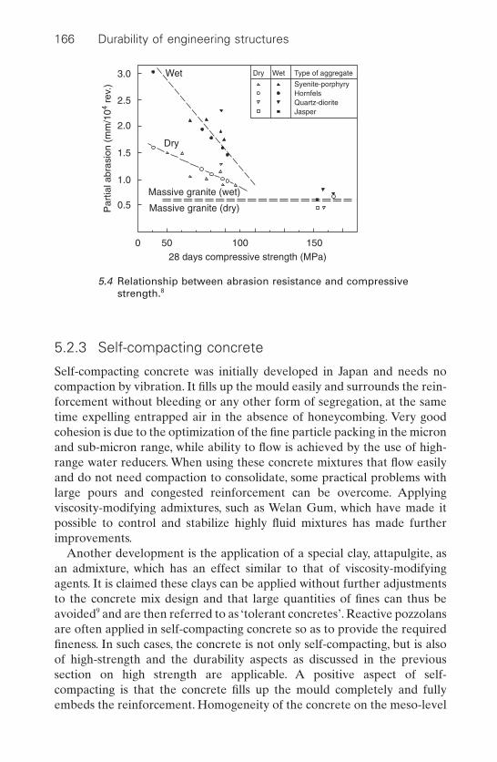
166 Durability of engineering structures
5.2.3 Self-compacting concrete
Self-compacting concrete was initially developed in Japan and needs nocompaction by vibration. It fills up the mould easily and surrounds the rein-forcement without bleeding or any other form of segregation, at the sametime expelling entrapped air in the absence of honeycombing. Very goodcohesion is due to the optimization of the fine particle packing in the micronand sub-micron range, while ability to flow is achieved by the use of high-range water reducers. When using these concrete mixtures that flow easilyand do not need compaction to consolidate, some practical problems withlarge pours and congested reinforcement can be overcome. Applying viscosity-modifying admixtures, such as Welan Gum, which have made itpossible to control and stabilize highly fluid mixtures has made furtherimprovements.
Another development is the application of a special clay, attapulgite, asan admixture, which has an effect similar to that of viscosity-modifyingagents. It is claimed these clays can be applied without further adjustmentsto the concrete mix design and that large quantities of fines can thus beavoided9 and are then referred to as ‘tolerant concretes’. Reactive pozzolansare often applied in self-compacting concrete so as to provide the requiredfineness. In such cases, the concrete is not only self-compacting, but is alsoof high-strength and the durability aspects as discussed in the previoussection on high strength are applicable. A positive aspect of self-compacting is that the concrete fills up the mould completely and fullyembeds the reinforcement. Homogeneity of the concrete on the meso-level
Wet
Dry
Massive granite (wet)
Massive granite (dry)
0
0.5
1.0
2.0
3.0
1.5
2.5
50 10028 days compressive strength (MPa)
Par
tial a
bras
ion
(mm
/104
rev.
)
150
Dry Wet Type of aggregate
Syenite-porphyryHornfelsQuartz-dioriteJasper
5.4 Relationship between abrasion resistance and compressivestrength.8
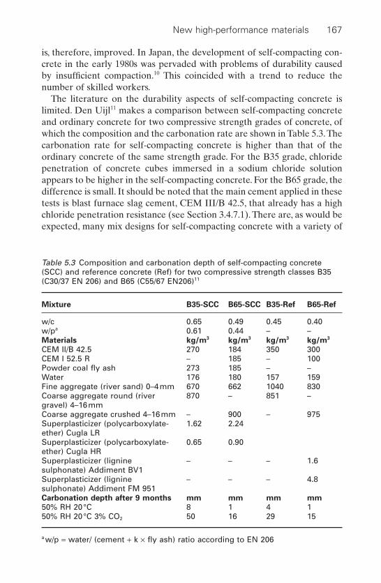
New high-performance materials 167
is, therefore, improved. In Japan, the development of self-compacting con-crete in the early 1980s was pervaded with problems of durability causedby insufficient compaction.10 This coincided with a trend to reduce thenumber of skilled workers.
The literature on the durability aspects of self-compacting concrete islimited. Den Uijl11 makes a comparison between self-compacting concreteand ordinary concrete for two compressive strength grades of concrete, ofwhich the composition and the carbonation rate are shown in Table 5.3.Thecarbonation rate for self-compacting concrete is higher than that of theordinary concrete of the same strength grade. For the B35 grade, chloridepenetration of concrete cubes immersed in a sodium chloride solutionappears to be higher in the self-compacting concrete. For the B65 grade, thedifference is small. It should be noted that the main cement applied in thesetests is blast furnace slag cement, CEM III/B 42.5, that already has a highchloride penetration resistance (see Section 3.4.7.1). There are, as would beexpected, many mix designs for self-compacting concrete with a variety of
Table 5.3 Composition and carbonation depth of self-compacting concrete(SCC) and reference concrete (Ref) for two compressive strength classes B35(C30/37 EN 206) and B65 (C55/67 EN206)11
Mixture B35-SCC B65-SCC B35-Ref B65-Ref
w/c 0.65 0.49 0.45 0.40w/pa 0.61 0.44 – –Materials kg/m3 kg/m3 kg/m3 kg/m3
CEM II/B 42.5 270 184 350 300CEM I 52.5 R – 185 – 100Powder coal fly ash 273 185 – –Water 176 180 157 159Fine aggregate (river sand) 0–4mm 670 662 1040 830Coarse aggregate round (river 870 – 851 –gravel) 4–16mmCoarse aggregate crushed 4–16mm – 900 – 975Superplasticizer (polycarboxylate- 1.62 2.24ether) Cugla LRSuperplasticizer (polycarboxylate- 0.65 0.90ether) Cugla HRSuperplasticizer (lignine – – – 1.6sulphonate) Addiment BV1Superplasticizer (lignine – – – 4.8sulphonate) Addiment FM 951Carbonation depth after 9 months mm mm mm mm
50% RH 20°C 8 1 4 150% RH 20°C 3% CO2 50 16 29 15
a w/p = water/ (cement + k ¥ fly ash) ratio according to EN 206
raw materials. Nevertheless, the results indicate that the durability of self-compacting concrete is not superior to that of ordinary concrete compositions.
5.3 High-performance steel
High-strength steels have existed for many years but have not been verysuccessful in the construction market because of poor weldability and lowtoughness. The steel industry has put a considerable amount of effort intothe development of new high-performance steels with the following char-acteristics in relation to conventional steel:
• Higher strength and toughness.• Improved weldability and decreased sensitivity to hydrogen-induced
cracking.• The same or improved corrosion resistance.
This has been achieved by reducing substantially the carbon and sulphurcontents and by applying the techniques of ‘thermo-mechanical rolling con-trolled processing’ (TMCP), and ‘quench and temper’ (QT).12,13 Steel gradessuch as S355 and S460 (EN10113) that are made using these techniquesshow good weldability in comparison with conventional steels, notwith-standing their high yield stress. Even higher strength grade steels appear tobe possible without losing the characteristics targeted.
As discussed in Section 2.3.2.12 and Section 6.7.6 fatigue resistance andfracture toughness are of special interest for bridges and more particularlyfor bridge decks.These high-performance steels show a much better fracturetoughness than conventional steels, while the fatigue resistance is similar orbetter. The corrosion resistance appears to be similar or slightly better thanthat of conventional steel, although long-term atmospheric corrosion testsare not available at present (durability, mainly focussing on the corrosionresistance of steel and steel alloys, is discussed in Chapter 2). High-perfor-mance steels can therefore be used to increase the service life of structures,especially where dynamic loading is applied, such as in bridge decks, as wellas for a leaner construction where it is likely that the higher costs of this steelare easily compensated by a lower quantity of material used.
5.4 Fibre-reinforced polymers
5.4.1 General
Fibre-reinforced polymers (FRP) are composed of fibres and a polymermatrix. The fibres provide the primary strength and the matrix holds thereinforcement in its proper orientation for optimum properties. The fibres
168 Durability of engineering structures
used in civil engineering structures are made from glass (GFRP), carbon(CFRP) and poly-aramid (AFRP). The polymer resins are either thermo-plastic or thermosetting resins. They are extensively used in diverse areasranging from boats, consumer goods, aircraft, automotive components andindustrial applications. Their use in civil engineering applications is rela-tively modest but growing.
FRP composites offer the following properties when compared withother materials used for structural applications: Their advantages are:
• Good resistance against natural weathering conditions.• Low to no maintenance.• Light-weight.• High strength to weight ratio.• Flexibility in design.• High electrical resistance, but adjustable.• Easy to tool.• Colour and finish moulded-in.
Their disadvantages are:
• Low fire resistance.• Lower stiffness.• Higher initial production cost.
With respect to the fire resistance, it should be noticed that due to the lowheat conductivity of FRPs, failure in a fire could take more time than itwould in a comparable steel structure.
When considering the durability of engineering structures, the followinguses of FRP are considered important:
• As the main composite construction material in structures with func-tions similar to those traditionally made of steel, concrete or wood. Thecomposite shows some similarities to reinforced concrete. Higher concentrations of reinforcement will be applied where there is a requirement for tensile strength, whereas higher polymer content willbe applied where there is no such requirement. In general, the averagefibre content will not exceed 20%.
• As a composite material so as to reinforce existing structures, either torestore the minimum performance requirements or to extend the func-tion of the structure.The fibre percentage will be in the order of 50–70%for strips and 25–35% for sheets.
• As bars and tendons to replace steel cables, tendons and bars embeddedin concrete structures. The fibre percentage can then be as high as 80%.
Fibres can be manufactured in a continuous or discontinuous (chopped)form. Continuous fibres are used for structural applications, occasionally in
New high-performance materials 169
combination with chopped fibres. The fibres are often produced as strandsconsisting of hundreds of individual fibres, each individual fibre having adiameter ranging from 5 to 20 mm. Various matrices can be applied but fibrepolyester for glass, vinyl ester for aramid and epoxy for carbon fibres areused most frequently. It is these three composites that will be discussed.Thefirst issue under consideration is their durability and subsequently, theirpractical application will be described.
5.4.2 Durability aspects of FRP composites
5.4.2.1 Manufacturing process
Apart from the constituent material, FRP properties, notably durability,depend on the manufacturing process and quality control. Manufacturingprocesses can vary considerably and determine durability to a large extent.Sensitivity to deteriorating mechanisms, as discussed in the following sections, can be substantially higher for FRP manufactured on site whenrepairing structures using processes like wet lay-up with low-temperaturecure epoxies than for FRP products manufactured using autoclave mould-ing in a factory with high-temperature epoxies. Differences can result fromthe level of bonding between fibre and resin, the void content, the degreeof cure and the level of process-induced stresses.14
5.4.2.2 Strength
Glass, carbon and polyaramid fibres are very strong and stiff.Table 5.4 com-pares the properties of these fibres with those of mild steel. Figure 5.5 showsthe uniaxial tensile stress strain curve for these materials.15 Fibres arestronger than steel, less stiff than or as stiff as steel and show a more brittlebehaviour; i.e. there is linear elastic behaviour until failure, while steelyields. The variation in strength and stiffness depends on the type of carbonfibres used. These fibres are normally based on either pitch or polyacry-lonitrile (PAN) used as a raw material. Pitch fibres are fabricated fromrefined petroleum or coal pitch. PAN fibres are made of polyacrylonitrilethat is carbonized through burning. The PAN fibres offer the higheststrength and/or E-modulus.
5.4.2.3 Moisture sensitivity of polymer
FRP composites have a long history of use in marine vessels, piping, cor-rosion equipment and underground storage tanks. Experience has shownthat they can be successfully engineered to have long service lives in contactwith moisture and aqueous solutions. However, it is a misconception that
170 Durability of engineering structures

New high-performance materials 171
FRP composites and polymers are ‘water-proof’ since moisture diffuses intoall organic polymers, leading to changes in properties. The primary effectof absorption is on the resin itself through hydrolysis and saponificationthat cause both reversible and irreversible changes in the polymer struc-ture. Apart from a change in the mechanical properties, osmotic effects inthe case of a poorly cured resin can cause surface blistering, as discussed in
Table 5.4 Typical properties of fibres for FRP14
Material Modulus of Tensile strength Ultimate tensile
elasticity (GPa) (MPa) strain (%)
Carbon fibreHigh strength 215–235 3500–4800 1.4–2.0Ultra-high strength 215–235 4500–6000 1.5–2.3High modulus 350–500 2500–3100 0.5–0.9Ultra-high modulus 500–700 2100–2400 0.2–0.4
Glass fibreE 70 1900–3000 3.0–4.5S 85–90 3500–4800 4.5–5.5
Aramid fibreLow modulus 70–80 3500–4100 4.3–5.0High modulus 115–130 3500–4000 2.5–3.5
Mild steel 200 400 25*
*Yield strain = 0.2%
CFRP
0.02
2
4
6s (GPa)
0.04
Mild steel
AFRP
GFRP
e
5.5 Uniaxial tension stress–strain diagrams for different unidirectionalFRPs and mild steel.15 CFRP = carbon FRP, AFRP = aramid FRP,GFRP = glass FRP.

Section 3.8.4.4. The absorption of moisture can also cause deleteriouseffects to the fibre-matrix bond resulting in loss of integrity. Furthermore,it causes a depression in the glass transition temperature14 (see Section5.4.2.7).
5.4.2.4 Alkaline and acid attack
Glass fibres used for continuous fibre reinforcement can be classified intothree types: E-glass fibres, S-glass fibres and alkali-resistant AR-glass fibres.E-glass fibres have a low alkali resistance. S-glass fibres are stronger andstiffer than E-glass, but still not resistant to alkali. To prevent glass fibrefrom being eroded by cement alkali, a considerable amount of zircon isadded to AR-glass fibres.
The alkaline resistance of glass fibres is important when such fibres arein contact with an alkaline material, such as concrete.Where stagnant watercomes into contact with glass alkalis, constituents can leach out of the glassand build up a highly alkaline environment in the water that will in turnaffect the silicate structure of the glass. This phenomenon is known to have occurred in glass fibre communication cables. Carbon fibres do notdeteriorate in a cementitious highly alkaline environment, but aramid fibres embedded in a vinyl ester alkaline medium may be susceptible.
All three composites resist acids well.
5.4.2.5 Stress corrosion, stress rupture, creep, fatigue
The effect of alkaline attack, as discussed in the previous section, is aggravated if the glass fibres are under stress and suffer stress corrosion.Stress corrosion depends on the fibre, the matrix, the stress level, the timeand the environment. GFRP and AFRP can exhibit tensile rupture undersustained stress, a phenomenon known as stress rupture. The tensilestrength of GFRP can drop to low values when the material is under per-manent tension.
Carbon fibres are relatively unaffected by stress corrosion up to highstress levels. GFRP and AFRP are both sensitive to creep. Fatigue behav-iour of the three FRPs discussed in this chapter is, in general, superior tothat of steel.
5.4.2.6 UV radiation
Polymeric materials degrade when exposed to UV radiation, which cancause dissociation of chemical bonds. The radicals formed then react withoxygen and chains in the polymeric materials become broken, cross-linkingcan occur and side-chains split off. The polymer matrix deteriorates first
172 Durability of engineering structures

because it surrounds the fibres. Of the fibres discussed here, glass andcarbon fibres are largely unaffected by UV radiation, while aramid fibresare only slightly affected. In general, FRP deterioration is only minor anddetermined by the resin matrix applied. A polyester matrix is more sensi-tive to UV radiation than is an epoxy one.
If FRP composites are exposed to the sun, it is recommended that theFRP composites are protected against UV radiation by applying paint.Acrylic-based and polyurethane paints generally show good UV resistance.The colour of the paint is also important; white paint reflects most of thesun’s radiation, while black paint absorbs most of it. On a sunny day, thiscan mean a temperature difference of 20 degrees centigrade between ablack- and white-coated FRP, which can have a major effect on the perfor-mance of the reinforcement of existing structures with FRP strips or sheetsfixed to the surface with an adhesive (see Section 5.4.4).
5.4.2.7 Glass transition temperature
As previously stated (in Section 3.8.4.3), thermo-resins have a glass–rubbertransition temperature in the usage temperature range of structures. Abovethe glass transition temperature, the modulus of elasticity decreases dra-matically and this results in reduced stress transfer. The ultimate load-carrying capacity can decrease by 30–40%.13 It is therefore important toensure that the glass transition temperature is higher than the maximumservice temperature of the structure or that part of the structure that con-tains the FRP reinforcement. One also has to be aware that water absorp-tion can cause a substantial decrease of the transition temperature. Henceit is critical that the FRP composite has a transition temperature that is atleast 30 degrees above the maximum service temperature so as to allow forthis potential depression.14 If the FRP is exposed to the sun, applying awhite coat of paint can reduce its maximum temperature.
5.4.3 Applications in structures with functions similar tothose of traditional materials
A growing number of mostly small span bridges are built partly or com-pletely using FRP. Especially in the USA, where the failure of bridges madefrom reinforced concrete is widespread, this relatively new material hasbeen welcomed as a solution to the problems of corrosion and de-icing saltdeterioration. Thus the 11m long and 8m wide Tech-21 bridge that consistsfully of FRP composites is being built in Butler County, Ohio, a state wherede-icing salt damage is severe. The different sections all consist of glassfibres embedded in various matrices. The total bridge weight is only about12 tons.
New high-performance materials 173
Another example is an FRP sluice door in the Netherlands.The door con-sists of a horizontal corrugated sheet manufactured by hand lay-up andfixed in a U-frame. In general, stiffness is not very important for sluice doorsso the relatively low stiffness of FRP is therefore not a disadvantage in thisapplication. Here again, the better corrosion resistance of FRP is a decid-ing factor, although initial costs are substantially higher. The Ramspol bal-gstuwkering (bellows water barrier) in the ‘Zwarte Meer’ (‘Black Lake’) inthe Netherlands is intended to protect the land against flooding. At timesof a high risk of flooding, a bellow made of fibre-reinforced polymer canvasis inflated with air. The inflated bellow floats on the water and forms abarrier against water ingress.The bellow is mostly under the water level andonly in times of incipient flooding will it be exposed to the air. The bellowis made of a fibre-reinforced rubber, which is, in fact, not strictly speaking,an FRP.
In general, structural use of FRP is subject to highly conservative safetyfactors, thus a strength safety factor of 4 to 5 is applied based on the com-bined action of stress rupture and fatigue, whereas much lower factors arethe rule for steel. This is a very careful approach, considering that, undersustained loading, glass fibre-reinforced composites can be used at a stresslevel of 25–30% of the ultimate stress.
In most of the applications of FRP described, long-term durabilitydepends strongly on the use of an appropriate gel-coat on the FRP surfacethat can effectively protect the underlying FRP against the deteriorationmechanisms discussed.
5.4.4 FRP as reinforcement in existing structures
5.4.4.1 General
The most extensive use of FRP in civil engineering is as reinforcement inexisting structures where, usually, the FRP is externally bonded. Extensiveinformation on the design and use of externally bonded fibre-reinforcedpolymer reinforcement (FRP EBR) in reinforced concrete structures isgiven in Reference 15. FRP can also be used for reinforcing steel and woodstructures. Carbon fibre reinforced CFPR strips are the most frequentlyapplied for reasons already given (Section 5.4.2.2).
Systems used to connect the FRP reinforcement to the existing structureare:
• Wet lay-up.• Adhesion of prefabricated elements.• Specials systems such as wrapping, prestressing.
Adhesion of prefabricated elements is the most frequently applied tech-nique and is similar to externally bonded steel reinforcement. However, the
174 Durability of engineering structures

use of FRP solves some of the problems associated with steel plates, suchas difficulties in positioning the heavy steel plates, the need for scaffoldingdue to weight, limited length, the threat of corrosion and the need to protectthe steel plates.
Another application of FRP is the reinforcement of concrete columns bywrapping FRP sheets around them.16 An alternative approach that has beenadopted for column strengthening is the use of prefabricated compositeshells, also called jackets. The annulus between the FRP shell and the exist-ing column is filled up with a cementitious grout or an epoxy material. Ifthese techniques are used on columns that are subject to chloride-initiatedreinforcement corrosion, it is essential that the corrosion be stopped priorto applying the FRP reinforcement. Although laboratory tests showed adecrease in the rate of corrosion after wrapping,17 practice has shown thatcorrosion continues.18 Corrosion could be stopped by applying a cathodicprotection system, for instance, by applying a zinc mesh as a sacrificialanode system inside the jacket, as discussed by Davison et al.19
5.4.4.2 Durability
The adhesive has the function of transferring the load from the structureto the FRP, so that full composite action can develop. Generally, the adhe-sive is epoxy resin-based.An epoxy resin is then mixed with a hardener and,depending on the application, other constituents, such as fillers or tough-ening or softening agents. The craftsmanship of surface preparation and theapplication of adhesive and reinforcing material are of great importance tothe quality of the external reinforcement.
Durability aspects of the FRP composites were discussed in Section 5.4.2where the adhesive and the interface between the structure and the FRPwere investigated. The effects discussed are also applicable to wet lay-up where the fibre/polymer composite is manufactured by applying bothfibre and polymer onto the surface; hardening of the matrix occurs afterapplication.
Attention should be paid to a number of aspects.
Glass transition temperature
As for the FRP itself, the adhesive must also have a glass transition tem-perature beyond the maximum service temperature. The effect of moistureabsorption by the resin at the transition temperature, as discussed in Section5.4.2.4, should be taken into account. This may present difficulties, par-ticularly if the strengthened member of the structure is subjected to hightemperatures.
New high-performance materials 175

Temperature dependence
The properties of the adhesive as well as the matrix of the FRP are tem-perature dependent.This should be taken into account by assessing the per-formance of a plate-bonded composite beam. In general, load tests haveshown that failure occurs in the adhesive at higher temperatures in theservice range, while interlaminar plate failure in the FRP has been observedat low temperatures.
Fire protection
In case of fire, the FRP external reinforcement will lose its function quickly.The adhesive will weaken and the polymer matrix will also be affected.When fire protection is provided, the FRP will stay in function longer. Thelength of the functional period has to be determined empirically.
Alkaline attack of adhesive
Since the adhesive of prefabricated FRP reinforcement is in direct contactwith the concrete substrate, the adhesive must be alkaline resistant. Ingeneral, epoxy resins show good resistance to alkaline attack.
Frost–thaw
Most tests show that the performance of externally bonded FRP is littleaffected in freeze–thaw cycles. Problems may arise if the quality of the con-crete is poor.12
5.4.5 FRP rods and tendons for reinforcing concrete
Pultruded FRP rods and tendons can reinforce concrete replacing steelrebars or prestressed concrete which in turn replace prestressing or post-tensioning cables or tendons. Pultrusion is possible in combination withfibre mats at an angle of 45 degrees. The use of FRP rods or tendons ismainly advocated for durability reasons, notably for corrosion resistance.Occasionally there can be other reasons such as their use in rooms wheresteel in walls and floors is not allowed because of installed magnetic reso-nance devices.
There has been much attention paid in the literature to the bond strengthbetween the FRP reinforcement and concrete. Stress transfer between con-crete and reinforcement is, however, warranted by friction. In the case ofsteel also, there is no chemical bond and the pull-out strength is greatlyenhanced by proper geometry of the rebar. ‘Bonding’ can thus be greatlyimproved, for instance, by having ribbons on the rebars by winding part of
176 Durability of engineering structures

the fibres around the rod and by sanding. In the case of concrete wherecracking occur due to tension loading, the cracks in FRP-reinforced con-crete would be substantially larger than in steel reinforced concrete becauseof the lower Young’s modulus of the FRP. This also depends on the FRPapplied, as shown in Fig. 5.5, which means that the modulus of elasticitydoes not have to be lower.
In general, the relevant deterioration mechanisms are discussed inSection 5.4.4.2. Of special interest is the resistance of the FRP to alkalinitybecause the cementitious binder in concrete considerably increases alka-linity. UV resistance is, however, of no consequence for reinforcementembedded in concrete.
5.5 References
1 Zia P, Ahmad S, Leming H, High-performance Concretes: a State-of-Art Report(1989–1994), FHWA-RD-97-030, Washington DC, Federal Highway Adminis-tration, 1996.
2 Bijen J, Blast Furnace Slag Cement for Durable Marine Structures, ‘s-Hertogenbosch, VNC/Betonprisma, 1996.
3 Kaptein N,‘Future developments in high strength concrete (toekomstige ontwik-kelingen in zeer-hogesterkte beton)’, Cement, 2002 54 256–63.
4 Mohammed T U, Fukute T, Yamaji T, Hamada H, ‘Long term durability of con-crete made with different water reducing chemical admixtures under marineenvironment’, Concrete for Extreme Conditions, Proceedings Int. Conf. Dundee,(eds) Dhir R K, McCarthy M J, Newlands M D, London, Thomas Telford, 2002233–43.
5 Bamforth P B, Price W F, ‘Factors influencing chloride ingress into marine struc-tures’, Proceedings Concrete 2000, Dundee, September 1993.
6 Vennesland O, Gjorv O E, ‘Silica concrete – protection against corrosion ofembedded steel’, Detroit, ACI SP-79, 1983 2 719–29.
7 Gjorv O E, ‘Durability’ in High Performance Concretes and Applications, (eds)Shah S P, Ahmad S K, London, Edward Arnold, 1994.
8 Gjorv O E, Baerland T, Ronning H R, ‘Abrasion resistance of high-strength con-crete pavements’, Concrete International, 1990 12(1) 45–8.
9 Concrete containing superplasticiser and palygorskite, Patent application PCTInternational Publication Number WO 00/35824, June 2000.
10 Okamura H, Ouchi M, ‘Self-compacting concrete. Development, present andfuture use; Proceedings of First International RILEM Symposium on Self-Compacting Concrete in Stockholm, Paris, RILEM, 1999 3–14.
11 Den Uijl J A, ‘Properties of self-compacting concrete (eigenschappen vanzelfverdichtend beton)’, Cement, 2002 6 88–94.
12 High Performance Steel Designers Guide, 2nd ed, American Iron and Steel Institute, 2002.
13 Hubo R, Hanus F E, ‘Thermomechanisch gewalst staal (thermo-mechanicallyrolled steel), Bouwen met staal 128, Jan/Feb 1996 12–15.
14 Karbhari V M, ‘Durability of FRP composites for civil infrastructure – myth,mystery or reality’ in Advanced Polymer Composites for Structural Applications
New high-performance materials 177
in Construction’, (eds) Shenoi R A, Moy S S J, Hollaway L C, London, ThomasTelford, 2002.
15 Externally bonded FRP Reinforcement for RC Structures, Lausanne, fib, bulletin14, 2001.
16 Loudon N, ‘A review of the use of fibre reinforced composites by the UKHighway Agency’, Composites Materials in Concrete Construction, ProceedingsInt. Conf. Dundee, (eds) Dhir R K, McCarthy M J, Newlands M D, London,Thomas Telford, 2002 189–200.
17 Debaiky A S, Green M F, Hope B B, ‘Carbon fibre-reinforced wraps for corro-sion control and rehabilitation of reinforced concrete columns’, ACI MaterialsJournal, 2002 99 129–37.
18 Hartt W H, Rapa M, Powers R G, ‘A condition assessment of pile jackets uponFlorida coastal bridge substructures’, Concrete for Extreme Conditions, Pro-ceedings Int. Conf. Dundee, (eds) Dhir R K, McCarthy M J, Newlands M D,London, Thomas Telford, 2002 263–76.
19 Davison N, Roberts A C,Taylor J M, ‘Electrochemical systems for repair of rein-forced concrete structures’, Repair, Rejuvenation and Enhancement of Concrete,Proceedings Int. Conf. Dundee, (eds) Dhir R K, McCarthy M J, Newlands M D,London, Thomas Telford, 2002 305–16.
178 Durability of engineering structures

6Strategies for durability design,
maintenance and repair
6.1 Introduction
Engineering Structures are designed to perform over a stated period of timewhich means that their functions must remain intact during the design servicelife. Essential functions, such as structural safety, should be met with a speci-fied reliability, not only on completion of the work but during the wholeservice life.This may look obvious, but in reality it is one of the most cumber-some aspects of the designing process. It is the rule rather than the excep-tion that structures show unforeseen defects in one or more functions duringthe design service life.As far as the design is concerned, this is due to the lackof prompt knowledge about the performance of structures and materials,which is reflected in the standards where guidance to determine the servicelife of products is generally very limited.Another factor is that a long servicelife is beyond the horizon of designers and builders, who are often not liablefor more than ten years, while many defects, such as reinforcement corrosionin concrete, manifest themselves only after this period. For these reasons thedesigners do not really have the incentive to attend to such matters.
Several durability problems are not due to the designer but to low-qualityjob execution. However, sometimes the design is less amenable to variabil-ity in the construction process. For instance, if very dense reinforcement is applied in concrete, it will be difficult to avoid segregation and honey-combing of the concrete, and if the thickness of a steel coating must fallwithin narrow boundaries, e.g. 300–100 mm to avoid cracking, this cannot beachieved at the edges and welds and cracking is then likely to occur regard-less of the quality of the application.
Design for durability should include the structure’s maintenance pro-gramme during service life. Often parts of the structure will have to bereplaced or repaired to maintain performance at an acceptable level during the design service life. This also includes inspection programmes tomonitor the structure’s performance. For instance, if steel with an organiccoating is applied to a structure that is exposed to the exterior, we know
179
this coating has to undergo regular maintenance during the service life ofthe structure.
In actuality most structures are designed without specifying the servicelife and the functions to be fulfilled and the structure is completed withoutoffering the client a maintenance programme. In theory, this could meanthat there is no maintenance required during the service life, but reality isdifferent, particularly in cases where durability is not intentionally takeninto account in the design process. In such cases, maintenance is a questionof an ad hoc reaction whenever a defect manifests itself. This reaction cancome too late in the case of a sudden decline in performance, e.g. in thecase of stress corrosion of steel tendons. Often, the moment unexpecteddefects appear, maintenance activities are triggered off, including the drafting of a maintenance programme for the future.
Design for durability is a matter of preventing deterioration of perfor-mance below a specified level of reliability and there are many ways ofdoing this. A variety of building products is often available to perform acertain function in the structure, e.g. steel, reinforced concrete or timberbeams in a bridge. Within a generic type of material or product, a varietyof qualities is available, e.g. high-performance concrete or plain concrete.The choice sometimes depends on the preference of the designer or client,but is more often a matter of cost. Costs have to be considered over thewhole service life; life-cycle costing is, therefore, attracting more and moreattention. An optimum has to be found while still meeting the minimumvalues of performance requirements. The environmental impact of struc-tures is becoming another aspect of optimization. Environmental life-cycleassessment of structures will gain importance in the near future. Sometimesthe environmental loading is capitalized and is made part of the costs.
In this chapter attention is paid to the following.
• Definitions.• Listing the threats endangering the structure and their associated effects.• Deem-to-satisfy approach and performance-based design.• Probabilistic approach to service life design.• Maintenance strategies.• Life-cycle costing.• Environmental life-cycle assessment.
6.2 Definitions
6.2.1 Functions and performance
Function: a function is a task that a product (building material, buildingelement or structure) has to comply with, e.g. a concrete pile has to bearthe load of a bridge.
180 Durability of engineering structures
Functional requirement: a requirement related to the function that theproduct has to meet.
Performance: behaviour related to use.
Performance requirement: a statement of the performance required.Performance requirements include structural safety, fire safety, weathertightness, energy demand and environmental burdens.
Often several features (characteristic properties) of the product arerequired so as to comply with a function. For instance, to carry loads abridge needs strength and stiffness. In this case one functional requirementis translated into two performance requirements.
Failure: A product fails if a performance requirement is no longer met.
Performance indicator: an indicator covers a specific aspect of the structure,e.g. bending of a beam.
6.2.2 Quality and reliability
Quality: Conformance to specification.1
Reliability: The probability that a product (building material, buildingelement or structure) will perform a required function, under stated con-ditions, for a stated period of time. Reliability is therefore the extension ofquality into the time domain and may be paraphrased as ‘the probability of non-failure in a given period’.1 Reliability = [1 – probability of failure(PFi)], see Section 6.5.
Reliability index: limit value given in codes for the minimum reliability tobe met.
6.2.3 Redundancy
Redundancy: the provision of more than one means of achieving a function.Active redundancy: all items remain operational prior to failure. Standbyredundancy: replicated items do not operate until needed.1
6.2.4 Service life and durability
Service life: the period of time during which the product performs the func-tions for which it is designed and used. This period can be restricted due totechnical reasons e.g. the product no longer meets the specified technicalfunctional requirements (technical service life) but it can also be that thenon-technical functional requirements of the product are no longer met,
Strategies for durability design, maintenance and repair 181

e.g. economic requirements (economic service life) or that the functionalrequirements themselves are changed in time.
Technical service life: the period of time during which all essential techni-cal properties meet or exceed minimum acceptable values when routinelymaintained. The technical service life must be in accordance with therequired service life.
Required service life: the service life specified to meet users’ requirements.
Design service life: the period of use intended by the designer. This designservice life should be no shorter than the required service life.
Serviceability: a product’s capability to perform the functions for which itis designed and used.
Serviceability limit state (SLS): if this limit state is exceeded the function-ing of the structure must be restricted. In structural codes this is, forinstance, the case if the deflection of a reinforced concrete beam exceeds acertain limit, e.g. 20mm. This principle can also be used for non-structuralitems, such as watertightness of a tunnel where the serviceability limit statethen is a certain amount of leakage water allowed.
Ultimate limit state (ULS): if this limit state is exceeded, the structure does not function. In structural engineering this means the structure hascollapsed, is fractured, etc.
Durability: the capability of a building, assembly, component, product orstructure to maintain its functions over at least a specified period of time.
Explicit design for durability: a design in which each relevant deteriorationmechanism is taken into account with the result that the probability offailure as a result of a decline in performance will not exceed a defined limitvalue within the design life.2
Implicit design for durability: a design where an exposure or environmen-tal class given in standard specifications for the specific application is chosenwith the prescriptive product requirements specific to that class. In a deem-to-satisfy approach, it is assumed that if these requirements are met, therequired design service life will be achieved.
Life-cycle cost: the total discounted cost of owning,operating,maintaining,anddisposing of or recycling a building or a building system over a period of time.
6.2.5 Maintenance and repair
Maintenance: refers to all activities aimed at maintaining and/or restoringa specified performance of a product (building materials, building elements
182 Durability of engineering structures
or structures). Such activities comprise not only execution of activities, butalso preparation and design. Maintenance activities can be divided into corrective, preventive and inspective maintenance.
Corrective maintenance (also called essential maintenance): concerns repairto restore functioning of the product (building materials, building elementsor structures) where the performance is unduly affected.
Preventive maintenance (prescribed): maintenance that is carried out peri-odically from the as new state, even in the absence of any sign of deterioration.
Preventive maintenance (reactive): regards preventive measures when sig-nificant loss of performance is found through condition monitoring and/orassessment,but on a level at which its performance is still not unduly affected.
Inspective maintenance: involves activities performed to assess the presentperformance of the product (building materials, building elements or struc-tures). It can be regarded as part of preventive maintenance.
Repair: restoring the functioning of products (building materials, buildingelements or structures).
Damage: in the case of damage, the performance of products (buildingmaterials, building elements or structures) is affected, the occurrence ofwhich was not predicted in the service life design. Figure 6.1. illustrates this.Curve a presents the predicted performance in time. Curve b is the actualperformance versus the time function. The maintenance required to keepperformance above the critical level has not been predicted with the resultthat damage has occurred. For instance, a concrete structure suffering fromreinforcement corrosion is damaged. The defect was not foreseen in thedesign and was not expected. A steel structure that needs a new topcoat for
Strategies for durability design, maintenance and repair 183
a
b
Criticallimit
Time
Design service life
Per
form
ance
6.1 Performance of building material, building component or structurein time:(a) no corrective or preventive maintenance required, no damage(b) corrective maintenance was necessary, damage.
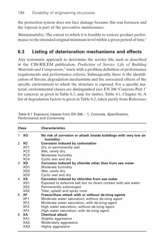
the protection system does not face damage because this was foreseen andthe topcoat is part of the preventive maintenance.
Maintainability: The extent to which it is feasible to restore product perfor-mance to the intended original minimum level within a given period of time.1
6.3 Listing of deterioration mechanisms and effects
Any systematic approach to determine the service life, such as described in the CIB-RILEM publication, Prediction of Service Life of Building Materials and Components,3 starts with a problem definition of performancerequirements and performance criteria. Subsequently, there is the identifi-cation of threats, degradation mechanisms and the associated effects of thespecific environment to which the structure is exposed. For a specific ma-terial, environmental classes are distinguished (see EN 206 ‘Concrete-Part 1’for concrete as given in Table 6.1, and, for timber, Table 4.1, Chapter 4). Alist of degradation factors is given in Table 6.2, taken partly from Reference
184 Durability of engineering structures
Table 6.1 Exposure classes from EN 206 - 1, Concrete, Specification,Performance and Conformity
Class Characteristics
1 XO No risk of corrosion or attack (inside buildings with very low air
humidity)
2 XC Corrosion induced by carbonation
XC1 Dry or permanently wetXC2 Wet, rarely dryXC3 Moderate humidityXC4 Cyclic wet and dry
3 XD Corrosion induced by chloride other than from sea water
XD1 Moderate humidityXD2 Wet, rarely dryXD3 Cyclic wet and dry
4 XS Corrosion induced by chlorides from sea water
XS1 Exposed to airborne salt but no direct contact with sea waterXS2 Permanently submergedXS3 Tidal, splash and spray zone
5 XF Freeze/thaw attack with or without de-icing agents
XF1 Moderate water saturation, without de-icing agentXF2 Moderate water saturation, with de-icing agentXF3 High water saturation, without de-icing agentXF4 High water saturation, with de-icing agent
6 XA Chemical attack
XA1 Slightly aggressiveXA2 Moderately aggressiveXA3 Highly aggressive
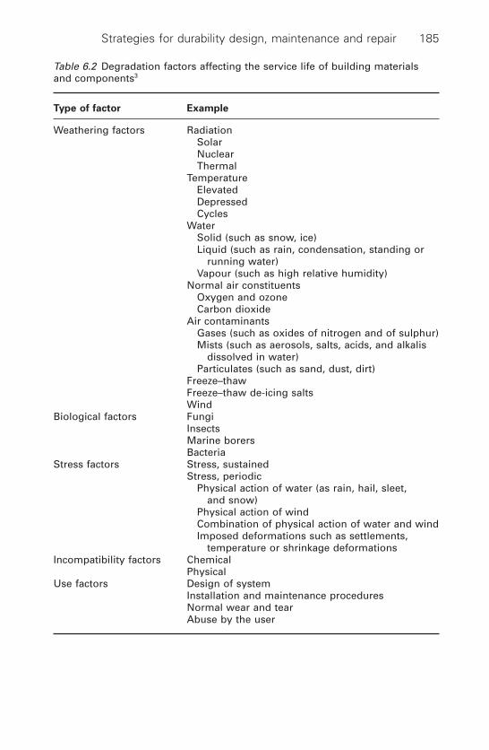
Strategies for durability design, maintenance and repair 185
Table 6.2 Degradation factors affecting the service life of building materialsand components3
Type of factor Example
Weathering factors RadiationSolarNuclearThermal
TemperatureElevatedDepressedCycles
WaterSolid (such as snow, ice)Liquid (such as rain, condensation, standing or
running water)Vapour (such as high relative humidity)
Normal air constituentsOxygen and ozoneCarbon dioxide
Air contaminantsGases (such as oxides of nitrogen and of sulphur)Mists (such as aerosols, salts, acids, and alkalis
dissolved in water)Particulates (such as sand, dust, dirt)
Freeze–thawFreeze–thaw de-icing saltsWind
Biological factors FungiInsectsMarine borersBacteria
Stress factors Stress, sustainedStress, periodic
Physical action of water (as rain, hail, sleet,and snow)
Physical action of windCombination of physical action of water and windImposed deformations such as settlements,
temperature or shrinkage deformationsIncompatibility factors Chemical
PhysicalUse factors Design of system
Installation and maintenance proceduresNormal wear and tearAbuse by the user
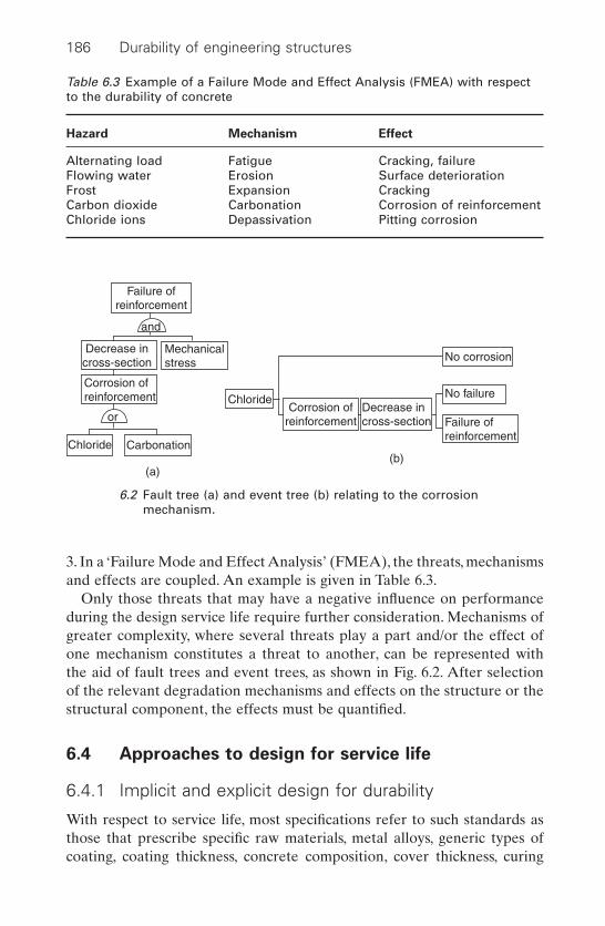
3. In a ‘Failure Mode and Effect Analysis’ (FMEA), the threats, mechanismsand effects are coupled. An example is given in Table 6.3.
Only those threats that may have a negative influence on performanceduring the design service life require further consideration. Mechanisms ofgreater complexity, where several threats play a part and/or the effect ofone mechanism constitutes a threat to another, can be represented with the aid of fault trees and event trees, as shown in Fig. 6.2. After selection of the relevant degradation mechanisms and effects on the structure or thestructural component, the effects must be quantified.
6.4 Approaches to design for service life
6.4.1 Implicit and explicit design for durability
With respect to service life, most specifications refer to such standards asthose that prescribe specific raw materials, metal alloys, generic types ofcoating, coating thickness, concrete composition, cover thickness, curing
186 Durability of engineering structures
Table 6.3 Example of a Failure Mode and Effect Analysis (FMEA) with respectto the durability of concrete
Hazard Mechanism Effect
Alternating load Fatigue Cracking, failureFlowing water Erosion Surface deteriorationFrost Expansion CrackingCarbon dioxide Carbonation Corrosion of reinforcementChloride ions Depassivation Pitting corrosion
Failure ofreinforcement
and
Mechanicalstress
Decrease incross-section
Corrosion ofreinforcement
or
Chloride Carbonation
Chloride
(a)(b)
No corrosion
No failure
Failure ofreinforcement
Corrosion ofreinforcement
Decrease incross-section
6.2 Fault tree (a) and event tree (b) relating to the corrosionmechanism.
conditions, allowable crack width and type of wood in specific environ-ments. It is assumed that meeting these specifications will ensure a longservice life.
Often, service life length is not specified. If the service life is specified or imposed by building regulations (e.g. reliability indices for structuralsafety safeguarded over 50 years), it is then implicitly assumed in a deem-to-satisfy approach that if these prescriptive requirements are met while in use, the specified design service life will be achieved. In the case of a long term proven record in similar structures with similar materials and insimilar environments, this can be an effective approach. Initial testing and either deterministic or probabilistic calculations of service life are thennot required. If no such similarity exists, this approach can easily lead tofailure.
There are a number of reasons why there is a tendency to design explic-itly for service life by means of performance-based design instead of implic-itly by means of prescriptive specifications. These reasons are:
• Often the product standards do not sufficiently warrant the durabilityrequired to meet the service life requirements, e.g. applying the European Standard EN 206 to concrete is no guarantee that a rein-forced concrete structure in a marine environment will have, forinstance, a 75 year service life without reinforcement corrosion.
• Competition between different kinds of materials on the basis of dur-ability cannot be done objectively with the present deem-to-satisfyapproaches, as these are not based on the same starting points.
• Adoption of western standard prescriptive specifications for harsher climates in, for instance, the Gulf and other coastal areas with a hotclimate, has led to major economic damage.
• The variety of materials available for structural applications and theirprotection systems has grown rapidly over the last decade. As a resultof environmental pressure, new protective coating systems have beendeveloped for metals. In concrete, additions, admixtures, and secondaryaggregates, such as concrete granulates and new compositions such as self-levelling concrete have properties that are insufficiently covered or not covered at all by the old prescriptive requirements. Modifiedwoods are being developed due to a ban on preservatives for wood. Inall these cases it is not self-evident that the old prescriptive standardsstill apply.
• The market favours tailor-made materials and products; prescriptiverequirements can be a barrier to such developments.
• Responsibility for product performance is increasingly shifted to themanufacturer who can no longer hide behind standard prescriptive specifications.
Strategies for durability design, maintenance and repair 187

6.4.2 Performance-based design
6.4.2.1 Practice, test or model
Performance-based design for durability can be based on:
1 Monitoring the performance of structures or testing structures under in-use conditions.
2 Determination of the resistance in a standardized artificial environmentwhich accelerates the deterioration process, and which is selected afterconsideration of the relevant degradation mechanisms, e.g. a Weather-O-meter test for steel coating systems, frost–thaw de-icing salt tests forconcrete or for wood, ENV 12038, a test method for determining theresistance against wood-destroying Basidiomycetes (fungi, see Section4.2.1). This can also concern a phase in the deterioration process, e.g.an accelerated carbonation test for concrete, where only the initiationphase of the corrosion process is considered.
3 A performance indicator that is different from the actual one, which isregarded as representative for the resistance against a threat, e.g. com-pressive strength as an indicator of concrete durability.
4 A model that describes performance over time, as previously discussed.Input parameters in the model are determined in prescribed tests.
5 Combination of two or more of the above approaches.
Further comments can be made on the methods listed above.
• Re 1: Method, monitoring the performance of the structure when in useover time offers the most reliable results. However, it is not feasible forapplication to new products. Another problem is that the history of thestructures is often not or poorly documented. Nevertheless, it is the goodperformance of steel and concrete structures in use that have resultedin market confidence in the reliability of these materials.Systematic monitoring of the performance of test structures and ofmaterials under practical conditions is done on exposure farms.
• Re 2: In accelerated deterioration testing, the key feature is to ensurethat the accelerated or short-term tests bear a safe and economic rela-tion to the structure’s long-term performance.Especially in new materials and new protection systems, it appears thatexisting accelerated test methods often do not relate well to practice.For instance, frost–thaw de-icing tests such as CDF, SS 137244 andASTM C672 methods are well suited to predicting the resistance of concrete with dense aggregates, e.g. river gravel, yet when concrete granulate (crushed concrete coarse aggregate) is applied, concrete fails in the frost–thaw de-icing salt test, while in practice it does not.4
The frequently applied salt-spray test (ASTM B 117) for metal and
188 Durability of engineering structures
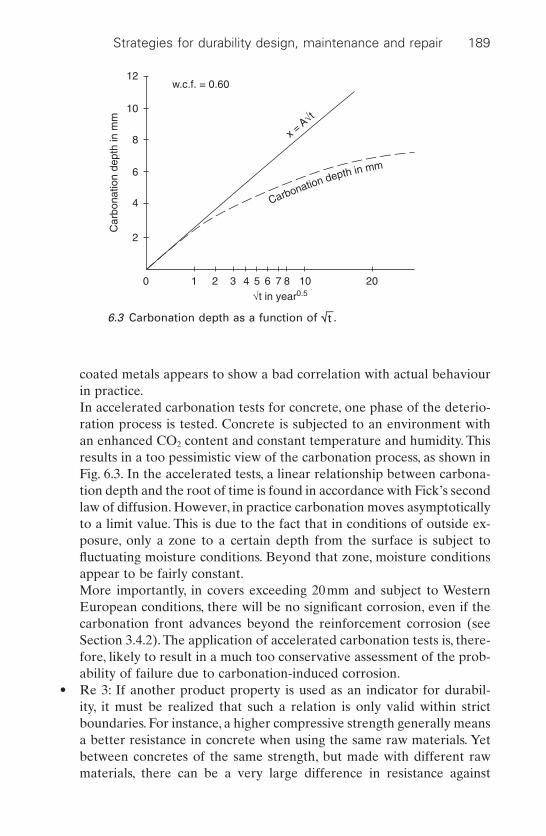
coated metals appears to show a bad correlation with actual behaviourin practice.In accelerated carbonation tests for concrete, one phase of the deterio-ration process is tested. Concrete is subjected to an environment withan enhanced CO2 content and constant temperature and humidity. Thisresults in a too pessimistic view of the carbonation process, as shown inFig. 6.3. In the accelerated tests, a linear relationship between carbona-tion depth and the root of time is found in accordance with Fick’s secondlaw of diffusion. However, in practice carbonation moves asymptoticallyto a limit value. This is due to the fact that in conditions of outside ex-posure, only a zone to a certain depth from the surface is subject to fluctuating moisture conditions. Beyond that zone, moisture conditionsappear to be fairly constant.More importantly, in covers exceeding 20mm and subject to WesternEuropean conditions, there will be no significant corrosion, even if thecarbonation front advances beyond the reinforcement corrosion (seeSection 3.4.2). The application of accelerated carbonation tests is, there-fore, likely to result in a much too conservative assessment of the prob-ability of failure due to carbonation-induced corrosion.
• Re 3: If another product property is used as an indicator for durabil-ity, it must be realized that such a relation is only valid within strictboundaries. For instance, a higher compressive strength generally meansa better resistance in concrete when using the same raw materials. Yetbetween concretes of the same strength, but made with different rawmaterials, there can be a very large difference in resistance against
Strategies for durability design, maintenance and repair 189
Carbonation depth in mm
0
2
4
6
8
10
12
1 2 3 4 5 6 7√t in year0.5
Car
bona
tion
dept
h in
mm
8 10 20
w.c.f. = 0.60
x = A√t
6.3 Carbonation depth as a function of ÷t–.
degradation mechanisms. Strength does not appear to be a dominantfactor for durability!
• Re 4: An example of a test that determines durability model parame-ters is discussed in Section 6.5.5.2. The input parameters can be the chloride diffusion coefficient and the cover thickness but a number ofconstants must also be determined at some stage. The key question hereis how well the model relates to actual chloride penetration when in use.The model does not take direct account of the convection of chlorideinto concrete due to water absorption, which, in Western Europe, is themost important penetration mechanism in the first 15mm from thesurface. Where the service lifetime is calculated by means of a model,there is always the question of how representative the model is in practice.
• Re 5: A combination of methods in most cases offers the best approach(see e.g. the next section).
6.4.2.2 Practical case: protection of steel structures
There is serious cracking of newly developed high solids epoxy-coatings onsea defence structures along the Dutch coast; this is discussed in Sections2.5.3.1 and 2.5.3.3.5 The specifications for these projects were mainly prescriptive and copied from previously applied epoxy-tar coatings, yetappeared to be unsuited to the new more environmentally-friendly coatingsystems applied. This prompted the Dutch government to change its spec-ification policy.A performance-based method was drafted consisting of foursteps:
1 The first step is problem definition. It describes the structure in relationto the protection to be applied. Threats, degradation mechanisms andthe associated effects are identified while taking into account the specific environment to which the structure is exposed.
2 The functional requirements are defined and translated into perfor-mance requirements.
3 Actual data gathering and testing of protection systems is carried out.4 The data gathered is analysed in relation to the performance require-
ments and conclusions about conformance are reached.
In step 2, a distinction is made into three classes of performance requirements:
• Proven good performance in practice.The protective system should have at least five years of proven experi-ence in similar applications. Criteria with regard to frequency and sizeof defects, such as blistering, cracking etc, are given.
190 Durability of engineering structures

• Accelerated degradation testsCurrently used accelerated weathering tests are:– TNO corrosion cabinet;– Weather-O-Meter (WOM) test;– salt water spray test ASTM B 117;– fresh water immersion test IS0 2812-2;– salt water immersion test ISO 2812-1.
• Modelling of cracking behaviour
A preliminary model is as follows:
[6.1]
whereu = Poisson coefficient of the coatingEcoating = mean E-modulus of the coating over the usage temper-
ature intervalC = mean relaxation coefficient over the usage temperature
intervalacoating = mean temperature expansion coefficient of coating
system over the usage temperature intervala steel = temperature expansion coefficient of steelDT = temperature changeeshrinkage = shrinkage of coating systemstensile strength = mean tensile strength of the coating over the usage tem-
perature interval
If there has been no practical experience over a minimum period of fiveyears and there are no alternatives, conformance to specifications has to bebased on accelerated deterioration tests and modelling. In such cases, theopinion of the expert must weigh heavily in the decision-making process.In generic new protection systems, the above performance criteria for accel-erated weathering and modelling must be considered thoroughly withregard to their representativeness in practice.
6.4.2.3 Responsibility
Performance requirements with respect to durability at the structural levelare mostly general in character. For instance, if a reinforced concrete bridgeis to have a maintenance-free service life of 75 years, such a requirementmeans that the designer and the contractor have the responsibility to design and construct a concrete structure with a service life of 75 years. Forinstance, the contractor of the King Fahad Causeway between Saudi Arabiaand Bahrain was asked to show that the durability of the concrete struc-ture was adequate for a service life of 75 years when routinely maintained.
1 1 -( ) ◊ -[ ] ◊ + ◊( ) £u a a D e sE T Ccoating coating steel shrinkage tensile strength
Strategies for durability design, maintenance and repair 191
This prompted the contractor to conduct an in-depth investigation intodurability in this harsh environment. As a result, the contractor proposedmajor changes to the design, most of which were accepted by the client.6
If performance requirements by the designer are set at the material level,e.g. strength of concrete must be grade 40 or the diffusivity of chloride ionsmust be 10-12 m2/s, then the designer is responsible for ensuring this specifi-cation warrants a maintenance-free service life of 75 years. The contractordoes not need to consider the 75 years but must only ensure that the require-ments at the material level are met. The legal possibility to claim indemnityfrom either designer or contractor differs greatly between countries.
6.4.2.4 Deterministic and probabilistic service life predictions
Service life predictions can be carried out in a deterministic or probabilisticway. Deterministic service life predictions take into account mean values.Theprobabilistic approach takes mean values and uncertainties into considera-tion and calculates the probability of failure or reliability. This is discussedin the next section. Sometimes it will be clear that a design is highly reliable.The structure is, for example, protected against an aggressive environmentby such items as tanking, membranes and coatings or corrosion is inhibitedby cathodic protection. In such cases, reliability calculations can be omitted.
6.5 Probabilistic approach to service life design
6.5.1 Analysis
In a probabilistic approach to service life design, the probability of failureand the extent of damage in case of failure must be assessed. The combi-nation of probability and damage, expressed as the mathematical productof the two, is called the risk. A condition for structural design is that theprobability of failure of a function will be lower than a limit value withinthe design service life. Limit values for the probability of failure in stan-dards for structural safety are very low. Table 6.4 gives an example of limitvalues for the probability of failure of buildings subject to wind loadingaccording to Dutch standards NEN 6700 and 6702. For other functionswhere there is no direct danger of loss of human life or the structure canremain operational while being repaired, e.g. rain tightness of buildingenvelopes, limit values can be much higher.
The durability design guide follows the same principles (reliability andperformances) as a structural design code.7 This means that durabilitydesign will be based upon:
• Realistic and sufficiently accurate definitions of environmental actions(different micro-environmental aggressiveness classes) depending onthe ensuing type of degradation.
192 Durability of engineering structures

• Material parameters.• Mathematical models for degradation processes.• Performances expressed as limit states.• Reliability.
6.5.2 Structural design
In modern codes, such as the Eurocode, the limit state function expressesthe basis of the conventional design procedure for structural safety and ser-viceability. This limit state defines the boundary between an adverse state(such as collapse, buckling, deflection, vibration) and the desired state. Thelimit state can, in principle, be formulated as:
[6.2]
where:R = a function that describes the load bearing capacity of the structureS = a function that describes the influence of the load on the structureXi = a basic variable for the functions R or S
The structural design procedure is elaborated in such a way that theprobability of failure is restricted:
[6.3]
where:P failure or Pf = the probability of failure of the structurePtarget = the accepted maximum value of the probability of failuref = standard normal distribution function (mean = 0 and
standard deviation = 1)b = reliability index (parameter normally used instead of the
probability of failure)
This probability of failure can be calculated with the aid of probabilistictechniques. In practice, however, the design has been simplified to a semi-probabilistic level with characteristic values and partial factors g calibratedin such a way that the target reliability will be achieved:
P failure P P R S Pf target = = - < < = -( )0 f b
R S R X X X S X X Xn n n m- = ( ) - ( ) =+ +1 2 1 2 0, , . . . , , , . . . ,
Strategies for durability design, maintenance and repair 193
Table 6.4 Limit values for probability of failure during reference time,compared with design service life in the case of predominant wind loading(according to Dutch standards 6700 and 6702)
Safety class 1 2 3
R = 15 years 6.9 10-4 3.4 10-4
R = 50 years 3.4 10-4 1.6 10-4
R = 100 years 1.6 10-4
[6.4]
whereRc = load-bearing capacity of the structure based on characteristic
valuesgR = material factorSc = characteristic value of the influence of loadinggS = load factor.Rd = design value of the load-bearing capacitySd = design value of the load
Calculation example for structural design
A relatively simple calculation example of such a limit state function canbe derived from Fig. 6.4.The beam has two supports and a rectangular cross-section. A concentrated load F loads the beam in the middle section. Thespan is l, the width b and the height h.
The maximum bending moment Mmiddle occurs in the middle section:
[6.5]
in case of linear elastic material behaviour, capacity Mmax of the middlesection is:
[6.6]
where:W = the section modulusf = the material strength (in this example either tensile or compressive
strength)
R M Wf bh fmax= = = 1 6 2
S M F l Flmiddle= = ¥ =2 2 14
R S R Sc R c S d dg g- ◊ = - > 0
194 Durability of engineering structures
F
F/2 F/2
l
b
h
6.4 Beam on two supports.

Equilibrium is possible as long as relationship [6.7] applies:
[6.7]
An overview of the parameters, including their stochastic characteristics, isgiven by way of example in Table 6.5. On the basis of this information, areliability index b = 4.0 can be calculated. For an ultimate limit state,Eurocode 1 has defined a reliability index of at least b = 3.8. The conclu-sion therefore is that this design is safe.
6.5.3 Time-dependent design
In performance-based structural design, both resistance R and load S areconsidered to be time independent. In many situations this is not realistic.The load can be time dependent or the capacity can change in time due to degradation. Relationship [6.2] should then be rewritten as a time-dependent limit state function8 taking such effects into consideration:
[6.8]
A special case for this limit state function occurs if either R or S is nottime dependent. These relationships do, in principle, not differ from thosein [6.2]. Relationship [6.8] applies to all values of t in the time interval (0,T).T is the intended service period (i.e. reference period). From a mathemati-cal point of view, it can be stated that relationship [6.8] can be used for durability design. The service life concept can be expressed in a designformula, similar to [6.2]:
[6.9]
where:Pf(T) = the probability of failure of the structure within TT = intended service period.
It will probably be possible to simplify relationship [6.9] at a later stage toone similar to that used in the conventional design procedure [6.4].
P T P R S Pf T ta rget( ) = - < < = -( )0 f b
R t S t( ) - ( ) > 0
R S or bh f Fl- > - >0 1 6 02 14
Strategies for durability design, maintenance and repair 195
Table 6.5 Parameters in the calculation example
Basis Description Distribution Mean Standard
variable deviation
b Beam width Deterministic 150mm –h Beam height Deterministic 400mm –F Concentrated load Normal 250kN 75kNl Span Deterministic 5000mm –f Material strength Normal 200N/mm2 20N/mm2
The mathematical model for describing the event ‘failure’, i.e. passing adurability limit state, comprises a load variable S and a resistance variableR (see Fig. 6.5). Failure occurs if the resistance is smaller than the load. Theprobability of failure within the period of time [0;T] Pf(T) is defined as theprobability that the load does not exceed the resistance within the givenperiod T.
[6.10]
The first step of this design will be the definition of the desired/requiredperformance(s) of the structure. The client or the owner of the structure isasked to define their requirements for quality and target service life.Further requirements can be given in building codes. The definition of per-formance criteria will be related to a limit state criterion.
Figure 6.6. shows an example of the performance (damage function) ofa concrete structure with respect to reinforcement corrosion and relatedlimit states. This example is taken from Reference 9, where a description isgiven of the Western Scheldt Tunnel in the Netherlands (see also Section6.5.5.2). The tunnel lining is loaded by salt (sea) water from the outside andsalt leakage water and de-icing salts from the inside. Due to the ingress ofchloride ions, depassivation of the reinforcement will occur and corrosioncan be initiated. If enough corrosion products have been formed, the con-crete cover will crack. Finally, spalling of the concrete cover will occur. Inthe last stage, the reduction of the cross-section of the reinforcing barsinvolved will end in the collapse of the structure. Depassivation and crack-ing in principle represent serviceability limit states related to durability.
P T P R t S t t Tf ( ) = - ( ) > ( ) " Œ[ ] 1 0;
196 Durability of engineering structures
Target service lifeService life distribution
Distributionof S(t) Mean service life
Distribution of R(t)
R, S
Time
Failure probabilityPf
Pf
R (t)
S (t)
6.5 Failure probability and target service life (illustrative presentation).

Collapse represents an ultimate limit state, whereas spalling can involveboth serviceability and safety related to durability.
Calculation example including a degradation model
The second step of the durability design is to analyse the environmentalactions and to identify the relevant degradation mechanisms. Mathemati-cal models describing the time-dependent degradation processes and the resistance of the material to it are needed. The big step forward in performance-related durability design is that these models enable thedesigner to evaluate the time-related changes in materials and structures,depending on specific material and environmental conditions. In this cal-culation example, we will simplify the approach by assuming only degra-dation of the material.
Further to the example given in Fig. 6.4, we assume that the dimensionsof the cross-section are reduced by xmm per year (see Fig. 6.7). This meansthat after a period t, the width is reduced to (b–xt) and the height to (h–xt).The original relationship [6.7] changes due to this degradation to:
[6.11]
In Table 6.6 a new set of parameters is defined, based on the parameterslisted in Table 6.5 and including the new parameter x. A probabilistic cal-culation based on these parameters results in the reliability indices given inFig. 6.8. For t = 0 we again come up with the original result b = 4.0. Thisvalue decreases in the course of time. After about 3.3 years, the value b =3.8 is exceeded. After about 65 years, the remaining reliability b = 0.0;meaning a 50% probability of failure.
R t S or b xt h xt f Fl( ) - > -( ) -( ) - >0 1 6 02 1
4
Strategies for durability design, maintenance and repair 197
DepassivationCracking
Initiation Propagation
Spalling
Collapse
Time
Damage
6.6 Determination of service life and limit states with respect toreinforcement corrosion (after Reference 9).

6.5.4 Case 1: Durability of a gallery slab
6.5.4.1 Introduction
A reinforced concrete outdoor gallery slab will be investigated so as to illus-trate optimization analysis in relation to durability.The slab is shown in Fig.6.9. In order to keep the problem within conveniently manageable limits,only the threat due to carbon dioxide will be considered. The mechanismconcerned is the carbonation of free lime and the effect is corrosion of themain reinforcement at the underside, manifesting itself in spalling of theconcrete cover.Four design situations are to be distinguished:
1 Cover of 15mm, no coating.2 Cover of 30mm, no coating.
198 Durability of engineering structures
Table 6.6 Parameters of the calculation example, including the rate of degradation
Basis Description Distribution Mean Standard
variable deviation
b Beam width Deterministic 150mm –h Beam height Deterministic 400mm –F Concentrated load Normal 250kN 75kNl Span Deterministic 5000mm –f Material strength Normal 200N/mm2 20N/mm2
x Rate of degradation Lognormal 1mm/year 0.05mm/year
hh–xt
b–xt
Original cross section
Cross section after a period tof degradation
b
6.7 Calculation example with a degraded cross-section.
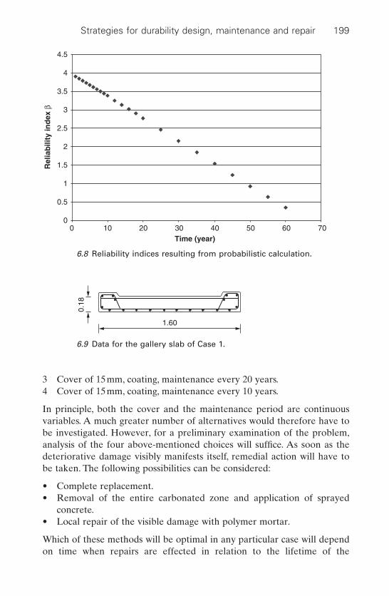
3 Cover of 15mm, coating, maintenance every 20 years.4 Cover of 15mm, coating, maintenance every 10 years.
In principle, both the cover and the maintenance period are continuousvariables. A much greater number of alternatives would therefore have tobe investigated. However, for a preliminary examination of the problem,analysis of the four above-mentioned choices will suffice. As soon as thedeteriorative damage visibly manifests itself, remedial action will have tobe taken. The following possibilities can be considered:
• Complete replacement.• Removal of the entire carbonated zone and application of sprayed
concrete.• Local repair of the visible damage with polymer mortar.
Which of these methods will be optimal in any particular case will dependon time when repairs are effected in relation to the lifetime of the
Strategies for durability design, maintenance and repair 199
0
0.5
1
1.5
2
2.5
3
3.5
4
4.5
0 10 20 30 40 50 60 70Time (year)
Rel
iab
ility
ind
ex β
6.8 Reliability indices resulting from probabilistic calculation.
1.60
0.18
6.9 Data for the gallery slab of Case 1.
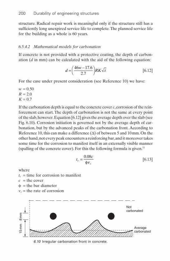
structure. Radical repair work is meaningful only if the structure still has asufficiently long unexpired service life to complete. The planned service lifefor the building as a whole is 60 years.
6.5.4.2 Mathematical models for carbonation
If concrete is not provided with a protective coating, the depth of carbon-ation (d in mm) can be calculated with the aid of the following equation:
[6.12]
For the case under present consideration (see Reference 10) we have:
w = 0.50R = 2.0K = 0.7
If the carbonation depth is equal to the concrete cover c, corrosion of the rein-forcement can start. The depth of carbonation is not the same at every pointof the slab,however.Equation [6.12] gives the average depth over the slab (seeFig. 6.10). Corrosion initiation is governed not by the average depth of car-bonation, but by the advanced peaks of the carbonation front. According toReference 10, this can make a difference (D) of between 5 and 10mm. On theother hand,not every peak encounters a reinforcing bar,and it moreover takessome time for the corrosion to manifest itself in an externally visible manner(spalling of the concrete cover). For this the following formula is given.11
[6.13]
wheretc = time for corrosion to manifestc = the coverf = the bar diametervc = the rate of corrosion
tc
cc
=0 08.fn
dw
RK t=-Ê
ˈ¯
46 17 62 7
..
200 Durability of engineering structures
Notcarbonated
Averagecarbonated
8 m
m15
mm
6.10 Irregular carbonation front in concrete.
In general, the time that elapses before corrosion damage becomesvisible can be calculated from the following formula, with replacement ofd in equation [6.12] by (d - D) or (c - D), because c is the cover thickness:
[6.14]
The influence of fluctuations in carbonation depth is taken into account by means of D for which an average value of about 5mm can be adopted.The corrosion rate vc is affected by considerable scatter. In the literature(Tuutti12 and Gonzales et al.13), values ranging from 0.015 to 0.09mm/yearare found. The constant is 0.08mm. Its purpose is to make equation [6.14]non-dimensional.
The question as to which is the appropriate model to be adopted fordescribing the carbonation process in concrete is still a subject of much discussion. By presenting equation [6.14], it is not the intention of thepresent report to take a position in this discussion. The only purpose is toshow that reliability analysis can be used for solving durability problems.The formula in question has, in this context, been chosen more or less arbitrarily.
In the slab considered in this example, the nominal cover is 15mm. Theactual cover can be assumed to be somewhat greater: let it be 20mm. Thereinforcement consists of 8mm diameter bars (f = 8mm) spaced at 150mmfrom centre to centre. If the previously stated values are adopted for w, R,K and E and if A and vc are taken as 5mm and 0.04mm/year, respectively,the following result is obtained for the service life:
The main contribution comes from the first term, the so-called initiationtime. If, in accordance with the second design alternative, the cover is takenas 30mm nominally (35mm in practice), then:
In that case, there is a marked increase in durability.If the underside of the concrete slab is provided with a coating that is
highly impermeable to carbon dioxide (chlorinated rubber or epoxy paint),the time period up to initiation of reinforcement attack can be consider-ably increased. It can be derived from the formulae given in Reference 10that this increase is expressed by:
[6.15]DD
td s
fL =-( )
180
tL = + =115 7 122 years
tL =-( )¥ ¥ -
ÊË
ˆ¯ +
¥¥
= + =20 5
2 0 0 72 7
46 0 5 17 60 08 208 0 04
29 5 342
2 2
2
. ..
. ..
.years
tcR K w
cL
c
=-( )
-ÊË
ˆ¯ +
D 2
2 2
22 7
46 17 60 08.
..fn
Strategies for durability design, maintenance and repair 201

where s is the thickness of the coating and f is the fraction of the surfacenot covered by the coating. As an example, an epoxy paint with s = 0.18mmand f = 10-5 is considered. Then:
[6.16]
The protective action of the coating is thus clearly demonstrated. This doespresuppose, however, that the values of s and f do not vary in the course oftime and also that the coating remains intact. This (ideal) situation can beapproximated if frequent inspection and maintenance are carried out.
As regards the thickness s of the coating, a rate of surface disintegrationof 3mm/year is mentioned by de Sitter10 based on the work of Klopfer.14 Fora normal maintenance cycle of 8–12 years, this rate is virtually negligiblei.e. the thickness of the coating would decrease for example from 0.18 mmto 0.15mm in 10 years. Only when longer intervals between maintenanceoperations are considered does this aspect become important.
Of greater significance is the time-dependent behaviour of f, at least ifphenomena such as damage and scaling-off are taken into account. Thereare, however, at present no data available on this. Meanwhile, pendingfurther information on the subject, the behaviour of f as a function of timewill be assumed to be as presented in Fig. 6.11. Based on this assumption,the logarithm of f increases linearly with time and the coating will haveentirely disappeared after about 50 years. This is expressed by the formula:
[6.17]f t f e t( ) = -0
a
DtL =-( )¥
=-
20 5 0 18180 10
15005
.years
202 Durability of engineering structures
0
95% confidence
m (L)
1
Impe
rfec
tion
frac
tion
f
10 20 30 40 50 60Time t (years)
10–1
10–2
10–3
10–4
10–5
10–6
Average
6.11 Assumed behaviour of the fraction f as a function of time t if nomaintenance is carried out.

If maintenance is carried out periodically, f(t) will show the familiar saw-tooth behaviour as presented in Fig. 6.12.
When calculating the corresponding service life, it will be assumed thatthe contribution made by the concrete itself is negligible in comparison withthe extra time gained by the coating. Since f(t) is time dependent, it is notpossible to make direct use of equation [6.17]. Some differential calculuswill have to be applied. During a very short period dt, the carbonation frontwill advance a very short distance dy. In analogy with equation [6.15], wethen have:
or:
Integration of both sides of the equation, from carbonation initiation (t =0, y = 0) to the point in time it reaches the reinforcement (t = tL, y = d -D),yields:
[6.18]
The right-hand integral is equal to s(d -D)/180. For the integral on the leftit is necessary to take account of the logarithmic saw-tooth pattern dis-played by f(t) according to Fig. 6.12. If the maintenance period is T, thenumber of maintenance cycles during service life is tL/T, so that the fol-lowing approximation can be made for this integral:
f t dtsdyt dL
( ) =Ú Ú-
0 0 180
D
f t dtsdy( ) =180
dtsdy
f t= ( )180
Strategies for durability design, maintenance and repair 203
01
T = 10 years
Fra
ctio
n f
10 20 30 40 50
t (years)
10–1
10–2
10–3
10–4
10–5
01
Fra
ctio
n f
10 20 30 40 50
t (years)
10–1
10–2
10–3
10–4
10–5
T = 20 years
6.12 Behaviour of f as a function of time t for maintenance every 10and 20 years respectively (saw-tooth model).
[6.19]
By equating the two expressions [6.18] and [6.19], we obtain the followingformula for the service life:
[6.20]
For T = 10 years: aT = (T/T0) lnf0 = (10/50) (-11.15) = -2.3, whence weobtain:
The earlier estimate of 1500 years for the service life is thus reduced to:
For T = 20 years: aT = (T/To) ln f0 = (20/50) ¥ (-11.5) = -4.6
For this 20 year maintenance period, the resistance that the concrete itselfoffers to the advance of carbonation, previously neglected, would certainlyappear worth taking into account. The carbonation times are allowed to beadded up, thus:
6.5.4.3 Quantification of uncertainties
In probabilistic calculations, a variable is described with the aid of a prob-ability density function. Such a function is in many cases characterized bya particular type of distribution (e.g. a normal distribution or a Weibull dis-tribution), a mean value m and a standard deviation s. Instead of the stan-dard deviation, the coefficient of variation (V = s/m) is often used. In theideal case, there are statistical data available for all the variables, enablingthe type of distribution, the mean value and the standard deviation to beunambiguously determined. In most cases, however, as in this example, theopposite applies, namely, there are no or, at best, scanty data available. Thestatistical properties will then have to be estimated. It is possible for manyvariables, based on information published in the literature, on experienceor on intuition, to specify values within which the variable in question islikely to fall. It is well known that, for the normal distribution, there is a
for T = 20 years: t yearsL = + =70 40 110
for T = 10 years: t yearsL = + =390 40 40
tL =-( ) ¥
¥= ¥ =-
20 5 0 18180 10
1500 0 047 705
.. years
tL =-( ) ¥
¥= ¥ =-
20 5 0 18180 10
0 26 1500 0 26 3905
.. . years
td s
fL =-( )D
1800 26
0.
td s
fTe
L T=
-( )-
ÊË
ˆ¯-
D180 10
aa
f t dttT
f e dttT
fe
tL t
TL T
L
( ) = = -( )Ú Ú - -
0
0
0
0 1a a
a
204 Durability of engineering structures
95% probability that a variable will have a value ranging m - 2s to m + 2s.It is thus possible to estimate the mean value and the standard deviation:
[6.21]
[6.22]
In a log-normal distribution, the corresponding formulae, if xhigh/xlow < 10,are:
[6.23]
[6.24]
The choice between using the normal or the log-normal distribution willdepend on the physical nature of the stochastic variable. Many variablesare by nature unable to take on negative values, and in such cases the log-normal distribution is to be preferred. For small values of the coefficient ofvariation (V < 0.10), the difference between normal and log-normal is neg-ligible for practical purposes. Where it is necessary to decide betweennormal or log-normal, on the one hand, and other potentially available distributions (e.g., extreme value distributions), on the other, the presentexample hardly seems to provide relevant arguments. The consequences ofchoosing a particular type of distribution for the stochastic variables will beconsidered later.
In Table 6.7, a choice has been made for the type of distribution, the meanvalue and the standard deviation for the various problem variables. Someof these variables have been taken as deterministic because the scatteraffecting them is considered to be very small. The mean values adopted arethose values rated as providing the best estimates in the preceding section.The coefficients of variation are largely based on estimates of the type indi-cated above. Only in the case of the concrete cover is it possible to use sta-tistical information obtained from measurements of cover depths in existingstructures.11
The least scatter is presumed to occur in the water/cement ratio.The coef-ficient of variation V(w) = 0.05 indicates with a 95% probability that thevalue of w is between 0.45 and 0.55. The scatter in, for example, R and K,is considered to be much greater. For the rate of corrosion vc the values0.015 and 0.09 have already been mentioned as the upper and lower limit.When applying equations [6.23] and [6.24], we obtain:
V vc( ) = =14
6 0 45ln .
m vc( ) = ¥ =0 015 0 090 0 036. . . mm year
V xxx
high
low
( ) = ÊË
ˆ¯
14
ln
m x x xhigh low( ) = -
s x x xhigh low( ) = -( )14
m x x xhigh low( ) = +( )12
Strategies for durability design, maintenance and repair 205
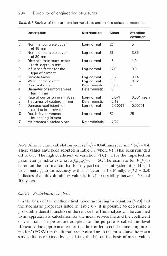
Note:A more exact calculation yields m(vc) = 0.040mm/year and V(vc) = 0.4.These values have been adopted in Table 6.7, where V(vc) has been roundedoff to 0.50. The high coefficient of variation V(f0) = 1 for the imperfectionparameter f0 indicates a ratio f0(high) /f0(low) = 50. The estimate for V(f0) is based on the information that for any particular paint system it is difficultto estimate f0 to an accuracy within a factor of 10. Finally, V(T0) = 0.50 indicates that this durability value is in all probability between 20 and 100 years.
6.5.4.4 Probabilistic analysis
On the basis of the mathematical model according to equation [6.20] andthe stochastic properties listed in Table 6.7, it is possible to determine aprobability density function of the service life.This analysis will be confinedto an approximate calculation for the mean service life and the coefficientof variation. The procedure adopted for the purpose is called the ‘levelII/mean value approximation’ or the ‘first order, second moment approxi-mation’ (FOSM) in the literature.15 According to this procedure, the meanservice life is obtained by calculating the life on the basis of mean values
206 Durability of engineering structures
Table 6.7 Review of the carbonation variables and their stochastic properties
Description Distribution Mean Standard
deviation
d Nominal concrete cover Log-normal 20 5of 15mm
d Nominal concrete cover Log-normal 35 3.85of 30mm
D Distance maximum–mean Log-normal 5 1.0carb. depth in mm
R Influence factor for the Log-normal 2.0 0.3type of cement
K Climate factor Log-normal 0.7 0.14w Water–cement ratio Log-normal 0.5 0.025E Constant mm Deterministic 0.08 –f Diameter of reinforcement Deterministic 8
bar in mmvc Rate of corrosion in mm/year Log-normal 0.0–1 0.50*means Thickness of coating in mm Deterministic 0.18 –f0 Damage coefficient for Log-normal 0.00001 0.00001
coating in mm/yearT0 Durability parameter Log-normal 50 25
for coating in yearT Maintenance period year Deterministic 10/20

for all the variables.The standard deviation is determined by linearizing thefunction t with the aid of a Taylor series. We then obtain:
[6.25]
in which tG = the target service life. The partial derivatives ∂tL/∂Xj are calcu-lated for the mean values of the stochastic variables.This calculation has beenperformed for all four alternatives and the results are given in Table 6.8.
The scatter in service life is found to be very great. Table 6.9 shows whichvariables are most responsible for this scatter. Thus it appears that withalternative (1) particularly, the depth of cover is of major influence. If thecover is increased, criteria such as the water/cement ratio and the climatefactor become more important. If a coating is applied, the durability valueT0 predominates if maintenance is carried out every 20 years, whereas theinitial imperfection coefficient f0 predominates if maintenance is carried outevery 10 years. It is particularly these variables that are affected by a highdegree of scatter that should receive most attention in further research.Table 6.9 reveals that a probability analysis is essentially a sensitivity analy-sis where the sensitivity ∂t/∂Xj of the variable Xj is weighed with a measurefor the variation, the standard deviation s(Xj), in relation to the scatter inthe service life.
s s2
2
1
ttX
XLL
jj
j
tG
( ) =∂∂
( )ÏÌÓ
¸˝˛=
Â
Strategies for durability design, maintenance and repair 207
Table 6.8 Calculation of
Variable Alternative
Xj Description 1 2 3 4d Cover 415 1561 1905 21994D Distance between max. 15 59 72 864
and mean carbonation depth
R Influence factor for type of 74 1187 74 74cement
K Climate factor 132 2111 132 132W Water/cement ratio 150 2395 150 150f Bar diameter – – – –vc Rate of corrosion 6 19 6 6s Coating thickness – – – –f0 Imperfection coefficient for – – 2304 112084
coatingT0 Durability value for coating – – 16178 89366T Maintenance period – – – –
s2(tL) 792 7333 20820 224672
s∂∂
s2
2
1
ttX
XLL
jj
j
tG
( ) = ( )ÏÌÓ
¸˝˛=
Â
By means of the calculations in previous sections, the mean value and thestandard deviation of the service life tL have now been determined.The dis-tribution of tL is as yet not known.The log-normal distribution should firstlybe considered as a possible choice: the service life definitely appears to bepositive and the scatter is large. On the basis of theoretical considerations,it can be shown that the distribution cannot be exactly log-normal. Accord-ing to equation [6.20], the service life is composed of three terms. For eachindividual term the log-normal distribution seems appropriate, multiplica-tion or division of variables conforming to this distribution will again yielda log-normally distributed variable. However, the sum of log-normally dis-tributed variables will certainly not follow a log-normal distribution but forthe present purpose what is exactly correct is less important than what will provide a serviceable model. To this end, the probability that the fouralternative solutions will fail within the intended service life of 60 years hasbeen calculated both on the basis of the log-normal model and with the aidof the ‘first order, second moment method’ (FOSM).15 In problems of thistype, the FOSM method provides an almost exact calculation of the prob-ability of failure. The results are presented in Table 6.10. From these resultsit can be inferred that the log-normal distribution yields good results fordetermining the probability of failure and given a mean value and standarddeviation. Finally, the service life distributions obtained for the first twoalternative design models are presented in Fig. 6.13 by way of illustration.
208 Durability of engineering structures
Table 6.9 Relative contributions of the stochastic variables to the service lifevariance for the four design alternatives
Variable Alternative
Xj Description 1 2 3 4d Cover 62 21 9 10D Distance between max. and 2 1 1 1
mean carbonation depthR Influence factor for type of 9 16 0 0
cementK Climate factor 17 29 1 0w Water/cement ratio 19 33 1 0f Bar diameter – – – –vc Rate of corrosion 1 0 0 0s Coating thickness – – – –f0 Imperfection coefficient for – – 11 50
coatingT0 Durability value for coating – – 78 40T Maintenance period – – – –
Total 110% 100% 100% 100%

6.5.5 Case 2: Western Scheldt tunnel, service life design
6.5.5.1 Introduction
In the previous case described in Section 6.5.4, it was concluded that it ispossible to use the same consistent design for safety, serviceability and dura-bility of structures with the aid of probabilistic analysis.The framework andthe design method for such a design were elaborated in the late 1990s in aEU research project named DuraCrete.16 The basis for this research wasthe result of previous work done by international organizations such asRILEM,8 IABSE17 and CEB.18 The first structure where the service life wasbased on the principles of this design method is the Western Scheldt Tunnelin the southern delta area of the Netherlands. The tunnel is fundamentallya bore tunnel made of prefabricated segments and two ramps made in situ,both in reinforced concrete. The tunnel offers a north–south road trafficconnection between peninsulas in the Dutch province of Zeeland, without
Strategies for durability design, maintenance and repair 209
Cover 15 mmm = 34 years
0 50 100
Cover 30 mmm = 123 years
Time t (years)
Pro
babi
lity
dens
ity f t
(t)
6.13 Service life distribution of two alternatives.
Table 6.10 Comparison of results on the basis of the log-normal distributionwith results obtained by the FOSM method
Design m(tL) s(tL) P(tL < 60) P(tL < 60)
alternative (year) (year) (log-normal (FOSM)
distribution)
1 34 28 0.86 0.762 123 86 0.20 0.133 103 144 0.50 0.394 417 474 0.05 0.05
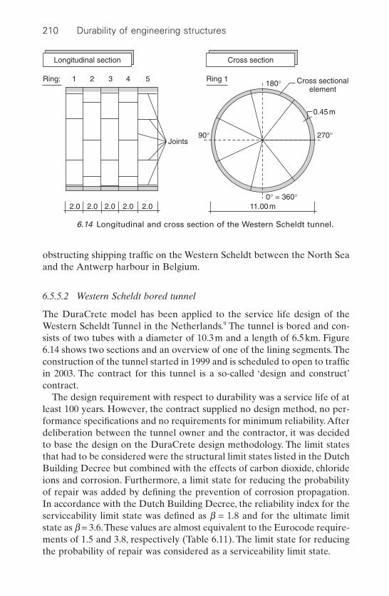
obstructing shipping traffic on the Western Scheldt between the North Seaand the Antwerp harbour in Belgium.
6.5.5.2 Western Scheldt bored tunnel
The DuraCrete model has been applied to the service life design of theWestern Scheldt Tunnel in the Netherlands.9 The tunnel is bored and con-sists of two tubes with a diameter of 10.3m and a length of 6.5km. Figure6.14 shows two sections and an overview of one of the lining segments. Theconstruction of the tunnel started in 1999 and is scheduled to open to trafficin 2003. The contract for this tunnel is a so-called ‘design and construct’ contract.
The design requirement with respect to durability was a service life of atleast 100 years. However, the contract supplied no design method, no per-formance specifications and no requirements for minimum reliability. Afterdeliberation between the tunnel owner and the contractor, it was decidedto base the design on the DuraCrete design methodology. The limit statesthat had to be considered were the structural limit states listed in the DutchBuilding Decree but combined with the effects of carbon dioxide, chlorideions and corrosion. Furthermore, a limit state for reducing the probabilityof repair was added by defining the prevention of corrosion propagation.In accordance with the Dutch Building Decree, the reliability index for theserviceability limit state was defined as b = 1.8 and for the ultimate limitstate as b = 3.6.These values are almost equivalent to the Eurocode require-ments of 1.5 and 3.8, respectively (Table 6.11). The limit state for reducingthe probability of repair was considered as a serviceability limit state.
210 Durability of engineering structures
Ring: 1 2 3 4 5 Ring 1
Longitudinal section Cross section
2.0 2.0 2.0 2.0 2.0 11.00 m
0.45 m
0° = 360°
90° 270°
180°
Joints
Cross sectionalelement
6.14 Longitudinal and cross section of the Western Scheldt tunnel.
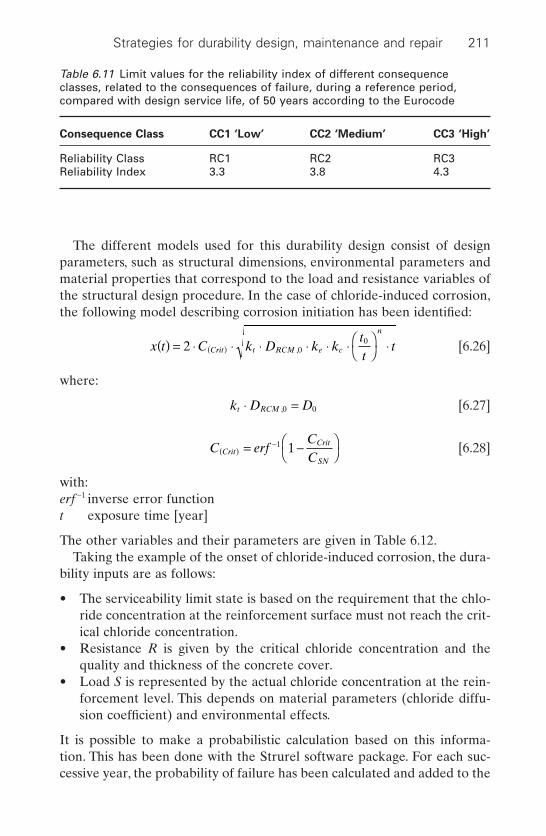
The different models used for this durability design consist of designparameters, such as structural dimensions, environmental parameters andmaterial properties that correspond to the load and resistance variables ofthe structural design procedure. In the case of chloride-induced corrosion,the following model describing corrosion initiation has been identified:
[6.26]
where:
[6.27]
[6.28]
with:erf -1 inverse error functiont exposure time [year]
The other variables and their parameters are given in Table 6.12.Taking the example of the onset of chloride-induced corrosion, the dura-
bility inputs are as follows:
• The serviceability limit state is based on the requirement that the chlo-ride concentration at the reinforcement surface must not reach the crit-ical chloride concentration.
• Resistance R is given by the critical chloride concentration and thequality and thickness of the concrete cover.
• Load S is represented by the actual chloride concentration at the rein-forcement level. This depends on material parameters (chloride diffu-sion coefficient) and environmental effects.
It is possible to make a probabilistic calculation based on this informa-tion. This has been done with the Strurel software package. For each suc-cessive year, the probability of failure has been calculated and added to the
C erfCCCrit
Crit
SN( )
-= -ÊË
ˆ¯
1 1
k D Dt RCM◊ =,0 0
x t C k D k ktt
tCrit t RCM e c
n
( ) = ◊ ◊ ◊ ◊ ◊ ◊ ÊË
ˆ¯ ◊( )2 0
0,
Strategies for durability design, maintenance and repair 211
Table 6.11 Limit values for the reliability index of different consequenceclasses, related to the consequences of failure, during a reference period,compared with design service life, of 50 years according to the Eurocode
Consequence Class CC1 ‘Low’ CC2 ‘Medium’ CC3 ‘High’
Reliability Class RC1 RC2 RC3Reliability Index 3.3 3.8 4.3
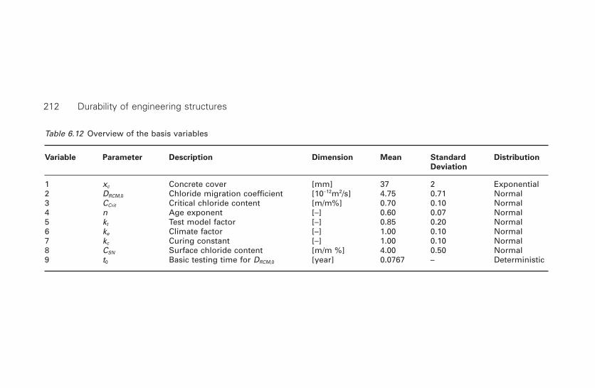
Table 6.12 Overview of the basis variables
Variable Parameter Description Dimension Mean Standard Distribution
Deviation
1 xc Concrete cover [mm] 37 2 Exponential2 DRCM,0 Chloride migration coefficient [10-12m2/s] 4.75 0.71 Normal3 CCrit Critical chloride content [m/m%] 0.70 0.10 Normal4 n Age exponent [–] 0.60 0.07 Normal5 kt Test model factor [–] 0.85 0.20 Normal6 ke Climate factor [–] 1.00 0.10 Normal7 kc Curing constant [–] 1.00 0.10 Normal8 CSN Surface chloride content [m/m %] 4.00 0.50 Normal9 t0 Basic testing time for DRCM,0 [year] 0.0767 – Deterministic
212 Durability of engineering structures
probabilities of failure of previous years. Furthermore, this value has beentransferred to the reliability index b.The result is presented in Fig. 6.15.Thefigure shows that the reliability index b = 1.5 after a period of 100 years.The design requirement was, however, b = 1.8 which meant that additionaldurability measures had to be applied.
6.6 Redundancy and over-design
Structures sometimes contain sections that are essential to safety, but giveno warning of imminent failure; they simply fail. Stress corrosion of thestainless steel hanging strips discussed in Section 2.4.3 caused sudden col-lapse of the swimming pool ceiling. When the first hangers failed, the otherstrips were not able to bear the load and failed too. Collapse of the south-ern part of the roof of the Berlin Congress Hall in 1980 happened withoutany warning and was due to stress corrosion of the prestressed cables.19
In maintenance strategies for manufacturing processes, the principle ofredundancy is widely accepted for those process steps for which failurewould have dramatic effects. The redundancy principle means that parallelto the critical section of the structure, another similar or different type ofsection with the same function is installed. This can take over the wholefunction as soon as the first section fails (standby redundancy). Alterna-tively, the two structural elements can both function (active redundancy),but if one of the two fails the other one can take over the full function.Figure 6.16 shows the effect of redundancy on reliability and failure rate.1
This principle is applied in civil engineering, but its application does notmake sense in terms of topmost durability. An example of the applicationof the redundancy principle is in the tensile piles of the retaining walls in
Strategies for durability design, maintenance and repair 213
20 30 40 50 60
Time of exposure in [a]
Rel
iabi
lity
inde
x b
[–]
70 80 90 1000
0.60
1.201.501.80
2.40
3.00
3.60
6.15 Reliability Index versus Time of Exposure.

the foundation of the new Alexandria library in Egypt. Double reinforce-ment is applied allowing one of the reinforcements to corrode away, whilestill leaving the redundant reinforcement to function in this harsh marineenvironment.20
If a structure design is inadequate and no deterioration processes havebeen taken into account, any decrease in the structural properties of struc-tural materials, such as corrosion in steel or fungal attack in wood, will leadto a situation where the safety requirements are no longer met. However,in most instances there is some overdesign present; for instance finiteelement calculations on the Deira–Shindagah tunnel in Dubai (see Section3.10) showed that the safety was still safeguarded, although some rebars 80mm in diameter were fully corroded. Owing to the (non-intentional) over-design, the tunnel does not have to be taken out of operation immediately.
6.7 Maintenance strategies
6.7.1 Maintenance as part of the design
Service life design should include maintenance of the structure. During thedesign stage a choice can be made between minimizing maintenance, opti-mizing the life-cycle costs, or optimizing the environmental effects of thestructure. In reality, maintenance is often not part of the design and a main-tenance programme at a later date is only begun as defects become obvious.
6.7.2 Objectives
In practice, maintenance of engineering structures has various objectives:
• Prevention of corrective maintenance and ensuring that the structurealways performs above a specified minimum level during its designservice life.
214 Durability of engineering structures
Reliability
Series
Time Time
2 Units
5 Units
5 Units
2 UnitsFailurerate
Series
0
l
6.16 Effect of redundancy on reliability and failure rate.1

• Repairing the structure in the best possible way.• Repairing the structure as quickly as possible.• Repairing the structure at the lowest cost.• Repairs should cause the least inconvenience to the users of the
structure.• Those parts that are affected should be replaced, preferably with stan-
dard spare parts rather than allowing repairs to take place.• Repairs should be made in such a way that further corrective or pre-
ventive maintenance is no longer required during the remaining servicelife.
• Repairing the structure and at the same time extending or adding newfunctions to the structure.
• Optimizing the maintenance cost at a specified state of performance.• Optimizing the cost for the time the structure is non-operational
because of repairs.• Optimizing the cost of maintenance and non-operation.• Optimizing the life-cycle costs of the structure.
Cost-optimizing strategies will be discussed in Section 6.8.
6.7.3 Factors influencing the choice of strategy
The maintenance strategy chosen depends largely on the structure, thedegradation mechanism(s) and the situation in question. If the structure isan office building, nuisance to the users will be an important factor. Duringthe repairs on the Deira–Shindagh tunnel, discussed in Section 3.10, one ofthe tunnel bores had to remain in use because there were no nearby alter-natives for traffic to pass the Dubai Creek. Replacement of the steel barrierplates in the Eastern Scheldt storm-surge barriers with fibre-reinforcedpolymer (FRP) sheets or thin high-strength reinforced concrete slabs hasbeen considered, yet the consequence of having to change the wholehydraulic lifting system is problematic in terms of dimensions and weight.
If the degradation mechanisms are such that the structure shows signsthat something is wrong, for instance the appearance of cracks over thereinforcement indicating corrosion or blisters on the steel structure coating,it is time to develop an optimum maintenance programme. If a sudden col-lapse of the structure is possible, however, for instance if stress corrosion isdetected in the steel tendons of a suspension bridge, immediate action isrequired.
6.7.4 Inspective, preventive and corrective maintenance
Inspection is part of any maintenance management system. The type ofinspection to be carried out depends on the structure in question, the
Strategies for durability design, maintenance and repair 215

inspection techniques available and the maintenance strategy objectives, asdiscussed in Section 6.4.2. Visual inspection is still the most advancedmethod of inspection, but it can be assisted by other methods, such as half-cell measurements for reinforcement corrosion, rebound hammering todetect any deterioration of wood or concrete and built-in corrosion cellsenabling continuous monitoring of chloride penetration in concrete structures.
Inspection frequency can take account of the high occurrence or so-calledbath-tub curve of the failure rate, shown in Fig. 6.17. This concerns all kindsof failures in various parts of a structure. Directly after completion of thestructure, the failure rate is high, i.e. so-called early failures or infant mor-tality failures. In engineering structures, this concerns incidents such asfailing joints and electrical devices that do not function. Thus the failinghigh-solids epoxy coating on the Eastern Scheldt barrier, as discussed inSection 2.5.3.1, can be regarded as an early failure. The failure rate subse-quently decreases to a lower level, where it remains until the end of theservice life, when the failure rate increases again. Failures at the end of theservice life are different in nature to those at the beginning. They arestrongly related to ageing, e.g. reinforcement corrosion will manifest itselfat those locations where the cover was underspecified or the concretequality less. The bath-tub curve can also occur at intermediate time-intervals, e.g. when the technical service life of a protective coating systemon steel comes close to its end.
To avoid declining performance and the exceeding of a critical perfor-mance level limit, an inspective maintenance programme can be carried outthat monitors the structure against specific performance indicators. Whendeclining performance is observed and defects appear that indicate failurein the near future but performance is still below a critical level, preventivemeasures (reactive) can be taken to bring performance to a higher level sothe structure can continue to function during the remaining service life. Itcan also be the strategy to prescribe a preventive maintenance pro-gramme after completion of the structure or after repairing the structure.
216 Durability of engineering structures
Failurerate
Early failures
Useful life
Wear outfailures
Time
6.17 Bath-tub curve.
That means that maintenance is carried out regardless of actual perfor-mance, e.g. regular painting of steel structures. Action must be taken onceperformance falls below the acceptable level. This is called corrective main-tenance or essential maintenance (see Figure 6.1). Inspective maintenanceand prescribed preventive maintenance are part of a maintenance man-agement strategy. An optimum strategy depends on the objectives of main-tenance, as discussed in Section 6.7.2.
6.7.5 Maintainability and repairability
The definition of maintainability is: ‘The extent to which it is feasible thatthe performance of a product will be restored to the intended originalminimum level within a given period of time’. Repairability can be definedin a similar manner and is part of maintainability.
There are two factors determining maintainability:
• Accessibility of the structure to inspection so as to allow for proper diagnosis.
• Ease of remedial action to restore structural performance.
Diagnosis is promoted by:
• A simple and transparent design concept and execution.• Built-in or easy-to-apply test devices.• As-built drawings and maintenance manuals adjusted to the needs of
maintenance personnel.• Availability of expert maintenance personnel and foreign expertise.
Remedial actions are made easier:
• If vulnerable parts can be easily repaired, removed and replaced. Exam-ples are the following:– sliding bearing plates of steel, rubber and Teflon on bridge pier
heads show decreasing performance in time. If there is sufficientspace and bearing capacity on the pier heads, the bridge can be jack-eted and replacement can be carried out easily;
– easy replacement of bridge deck joints that have a service life ofpossibly 15 years;
– the possibility of easy instalment of a cathodic protection system byensuring electrical continuity of the reinforcement (e.g. in the GreatBelt Tunnel in Denmark) when reinforcement corrosion becomesan (unexpected) threat;
• If maintenance personnel are continuously available and spare parts arein stock. In the case of the King Fahad Causeway (see Section 3.4.3.2),for instance, a very strict maintenance programme is applied, mainte-nance materials are in stock and immediate action is taken when adefect is observed.
Strategies for durability design, maintenance and repair 217
6.7.6 Maintenance and performance models
In the case of performance-based design for durability, models are occa-sionally used to predict the service life, e.g. the diffusion model for chlo-ride-initiated corrosion discussed in Section 6.5.5.2. Practice can bedifferent from theory. Moreover, many durability problems with structuresare not due to failing designs, but to the inadequate quality of job execu-tion. It is, therefore, wise to monitor performance in structures against theseindicators, even if a maintenance-free service life was designed for. By mon-itoring chloride penetration, for instance, the design predictions can bechecked and adjusted if required.
In steel structures under dynamic loading, such as heavy traffic steelbridge decks, service life prediction is subject to considerable uncertain-ties.21 The models applied are unreliable. By monitoring stresses and strainsin practice, performance can be followed properly and predictions aboutbehaviour can be highly reliable.21 This obviously means that there is noreal durability design, but adequate maintenance is possible.
6.8 Life-cycle costing
6.8.1 General
Within the framework of specified requirements of structural performanceover the design service life, cost will be an important item to optimize. It isquite common when designing structures to consider only the investmentcosts of the building process, yet there is a growing awareness that this isonly part of the process. Low investments can mean high operational costsand maintenance costs where the total can exceed high investments withlow operational and maintenance costs. Considering the cost of structuresover the whole life cycle is becoming increasingly popular.
Life-cycle costing is defined as the total discounted cost of owning, oper-ating, maintaining, and disposing or recycling a structure or a buildingsystem over a period of time.
In this section we will restrict ourselves to owning, operating and main-tenance costs, while elaborating on the probabilistic approach given inSection 6.5.
6.8.2 Principles of cost analysis
6.8.2.1 Capitalizing costs
The cost analysis of a building can be based on annual cost or on capital-ized cost. In the former case, the investment cost of the building is trans-
218 Durability of engineering structures

lated into an annual amount comprising interest and redemption. In thelatter case, i.e. involving capitalization of cost, every future expenditure isconverted back to an amount that can be added to the direct investments.In principle, both approaches lead to the same conclusions.
In some cases, termination of the service life of a part, member or com-ponent of a structure is determined solely by its ability to perform its func-tion: as soon as it fails to satisfy the functional requirements (and assumingthat repair is too expensive), it is replaced (window-pane, electric bulb,motor). External factors can also determine the service life, however. Forexample, an offshore drilling platform need not have a service life of morethan 30 years because the oil well in question will be exhausted by the endof that period. All that is required of the structure and its members is thatthey will not give rise to problems within the service life.A similar approachmay be adopted with regard to housing or industrial building construction,based on an intended service life of, for example, 50 years. If a member ofthe structure fails in one way or another within that period, it means thatdamage will occur, necessitating replacement or repair.
In the present section on capitalized cost, only the case of intended‘target’ service life will be considered. For many purposes, it will suffice toconceive the anticipated capitalized cost as being composed of three terms:the direct investment (initial expenditure), the cost of maintenance and therisk (anticipated loss, being the cost incurred when remedying deteriora-tion or damage). Both maintenance cost and loss due to deterioration ordamage must be calculated for each year of planned service life and thenbe capitalized and added up:
[6.29]
whereECcap = Expectation of the capitalized cost Ccap
S = Direct investmentVj = Maintenance cost and administration expenses for year jPFj = Probability of failure in year jDj = Loss due to failure in year jr¢ = Real rate of interest (nominal rate minus inflation)tG = Target service life (in years)
The probability of failure PF in year j follows from the probability distri-bution for service life tL (in years) (see Figs 6.18 and 6.19).
[6.30]
Alternatively, we can start from the probability density function ftL(t) asfollows:
P F P j t j F j F jj L t tL L = -( ) £ < = ( ) - -( )1 1
E C SV
r
P F D
rcap
j
jj
tj j
jj
tG G
= ++ ¢( )
+
+ ¢( )= =Â Â
1 11 1
Strategies for durability design, maintenance and repair 219
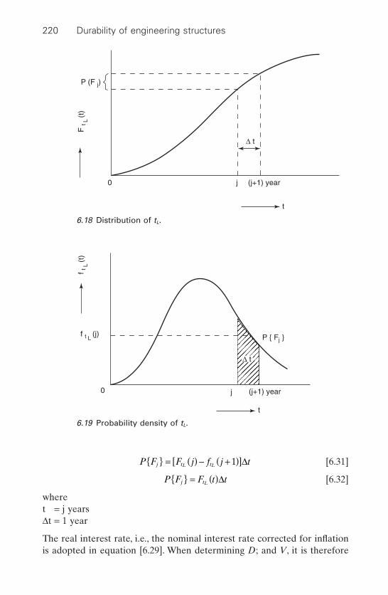
[6.31]
[6.32]
wheret = j yearsDt = 1 year
The real interest rate, i.e., the nominal interest rate corrected for inflationis adopted in equation [6.29]. When determining D; and V, it is therefore
P F F t tj tL = ( )D
P F F j f j tj t tL L = ( ) - +( )[ ]1 D
220 Durability of engineering structures
0 j (j+1) year
t
F t
L (t
)P (F j)
∆ t
6.18 Distribution of tL.
∆ t
f t L (j)
f t L
(t)
0 j
t
(j+1) year
P Fj
6.19 Probability density of tL.
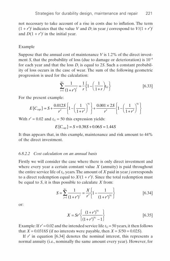
not necessary to take account of a rise in costs due to inflation. The term(1 + r¢)j indicates that the value V and D; in year j correspond to V/(1 + r¢)j
and D(1 + r¢)j in the initial year.
Example
Suppose that the annual cost of maintenance V is 1.2% of the direct invest-ment S, that the probability of loss (due to damage or deterioration) is 10-4
for each year and that the loss Dj is equal to 2S. Such a constant probabil-ity of loss occurs in the case of wear. The sum of the following geometricprogression is used for the calculation:
[6.33]
For the present example:
With r¢ = 0.02 and tG = 50 this expression yields:
It thus appears that, in this example, maintenance and risk amount to 44%of the direct investment.
6.8.2.2 Cost calculation on an annual basis
Firstly we will consider the case where there is only direct investment andwhere every year a certain constant value X (annuity) is paid throughoutthe entire service life of tG years.The amount of X paid in year j correspondsto a direct redemption equal to X/(1 + r¢)j. Since the total redemption mustbe equal to S, it is thus possible to calculate X from:
[6.34]
or:
[6.35]
Example: If r¢ = 0.02 and the intended service life tG = 50 years, it then followsthat X = 0.0318S (if no interests were payable, then X = S/50 = 0.02S).
If r¢ in equation [6.34] denotes the nominal interest, this represents anormal annuity (i.e., nominally the same amount every year). However, for
X Srr
r
t
t
G
G= ¢
+ ¢( )+ ¢( ) -
ÏÌÓ
¸˝˛
1
1 1
Sr
Xr r
jj
t
t
G
G=
+ ¢( )=
¢-
+ ¢( )ÏÌÓ
¸˝˛=
 1
11
1
11
E C S S S Scap = + + =0 38 0 06 1 44. . .
E C SS
r rS
r rcap
t tG G
= +¢
-+ ¢
ÊË
ˆ¯
ÏÌÓ
¸˝˛
+¥¢
-+ ¢
ÊË
ˆ¯
ÏÌÓ
¸˝˛
0 0121
11
0 001 21
11
. .
1
1
11
111 + ¢( )
= -+
ÊË
ˆ¯
ÏÌÓ¸˛=
Âr r r
ti G
i
tG
Strategies for durability design, maintenance and repair 221

the purpose of this book, it is preferable to work with the real interestbecause the annual increase of an amount then keeps pace with the pricelevel.
The cost of maintenance and risk can, if they are the same for each year, be directly added on. But if these costs are not constant, they must becapitalized and added to S, after which the value of X can be determinedwith the aid of equation [6.35]. The capitalized cost is, therefore, often amore suitable criterion for the optimization problems considered in thisbook.
In the foregoing, the real interest has always been incorporated and costincreases due to inflation have been left out. The drawback of this proce-dure is that the calculated amounts of money do not directly correspond tothe amounts actually payable.
Example
By way of illustration, an optimization problem will be dealt with in thissection. Here a simple carbonation problem is discussed where, for a givenservice life, the optimum depth of concrete cover is determined (see alsoSection 6.4.2).
Carbonation refers to the combining of free lime in concrete with carbondioxide from the atmosphere, as a result of which the pH in concrete islowered. If concrete thus ceases to have sufficient alkalinity, it loses its pro-tection and the reinforcing steel can corrode, which can be regarded as con-stituting the end of the service life.The following approximation (simplifiedmodel with respect to equation 6.12) for carbonation progress is used:
[6.36]
whered = the depth of carbonation (mm)A = a constant (mm2/year)t = the exposure time (years)
The service life tL is attained when carbonation depth d becomes equal tothe depth of concrete cover c:
[6.37]
For A = 10mm2/year, the service life tL of the concrete is given as a func-tion of c in Fig. 6.20. It appears from this diagram that a 24mm cover cor-responds to a service life of 60 years. Conversely, to obtain a service life of60 years, it will be necessary to provide a 24mm cover. If the cost of thecover is 0.20 euro per m2 of slab surface and per mm of cover thickness
tc
L =2
A
d t2 = A
222 Durability of engineering structures

(which is a reasonable figure for a concrete gallery slab), the required coverwill cost:
It is, however, not very realistic to conceive t service life as a deterministicquantity, for carbonation does not proceed everywhere at the same rate,and the depth of cover itself will never exactly conform to the nominal valueindicated on the drawing.
Assuming that Fig. 6.20 represents mean service life and that the actualvalues display a scatter in relation to this with a coefficient of variation of0.33, we obtain Fig. 6.21.
Ccap = ¥ =24 0.20 4.80 per m of slab2€
Strategies for durability design, maintenance and repair 223
20
10
0
Cov
er c
(m
m)
10 20 30 40 50 60
Service life tL (years)
6.20 Service life tL as a function of the cover c.
0
Cov
er c
(m
m)
10
20
30
10 20 30 40 50 60
Service life tL (years)
f L
m (tL)
6.21 Service life of the cover as a stochastic quantity.
Now, for a given depth of concrete cover, it is possible to calculate with what probability the entire cover will become carbonated within a certain period. The total capitalized cost according to equation [6.29] then is:
With S = 0.2c; Vj = 0; Dj = D and an intended service life tG = 60 years thisreduces to:
Because PFj is not constant, summation is difficult to carry out. The fol-lowing approximation can, therefore, be suitably adopted for equation[6.29.]:
[6.38]
What this approximation comes down to technically, i.e. from the financialpoint of view, is that every 60 years, failure is assumed to occur in the six-tieth year. The associated financial loss is somewhat underestimated.
The sum of the probabilities PFj for the years 1 to 60 is equal to theprobability of the service life being less than 60 years, so that:
[6.39]
If a normal distribution is adopted for tL, the probability that tL is less than60 years can be determined from:
[6.40]
where:F = standard normal distribution (m = 0 and s = 1)
For example, assuming c = 24mm (as found earlier on), we obtain m(tL) = 60 years, so that b = 0. The probability of failure then is 50%.For loss amounting to €25/m2 and a real interest rate r¢ = 0.02, it followsthat:
If a 30mm depth of concrete cover is chosen, the following results areobtained:
E Ccap = + = + =4 8025
1 020 50 4 80 3 80 8 6
602.
.. . . .€ 0 / m
P tL <( ) = -( )60 F b
E C cD
rP tcap L = +
+ ¢( )<( )0 2
160
60.
E C cD
rP tcap L = +
+ ¢( )<( )0 2
160
60.
E C c DP F
rcap
j
jj
= + + ¢( )=
Â0 211
60
.
E C SV
r
P F D
rcap
j
jj
tj j
jj
tG G
= ++ ¢( )
+
+ ¢( )= =Â Â
1 11 1
224 Durability of engineering structures

Increasing the cover results in an increase in direct cost and risk reduction,while the total cost expectation decreases.The optimum cover can be foundby repeating this calculation for a number of values of c, as indicated in Fig. 6.22. The optimum is obtained for c = 32mm, the probability of failurethen being 10%, in the present example.
6.8.3 Example of gallery slab maintenance costs
The lifetime costs for the various durability design alternatives of thebalcony slab discussed in Section 6.5.4.1 are calculated by way of example.
For the purpose of economic optimization, it is necessary to obtain insightinto the cost of the increased concrete cover, the application and mainte-nance of protective paint coatings and repairs. The cost figures adopted inthis example are given in Table 6.13. Uncertainties in these costs, and also
E Ccap = ¥ + = + =0 2 3025
1 020 16 6 1 2 7 2
60.
.. . . € m2
P t yearL < = -( ) = -( ) =60 1 0 16F Fb .
bm
s=
( ) -( ) =
-=
tt
L
L
60 90 6030
1
s tL( ) = ¥ =0 33 90 30. years
m tcaL( ) = = =2 900
1090 years
Strategies for durability design, maintenance and repair 225
0
10
20
10 20 30 40 50
Concrete cover c (mm)
32 mm
Total cost
14.30
Capitalizedrisk
Investment
EC
cap
(f)
6.22 Optimization of the depth of the cover with respect tocarbonation.
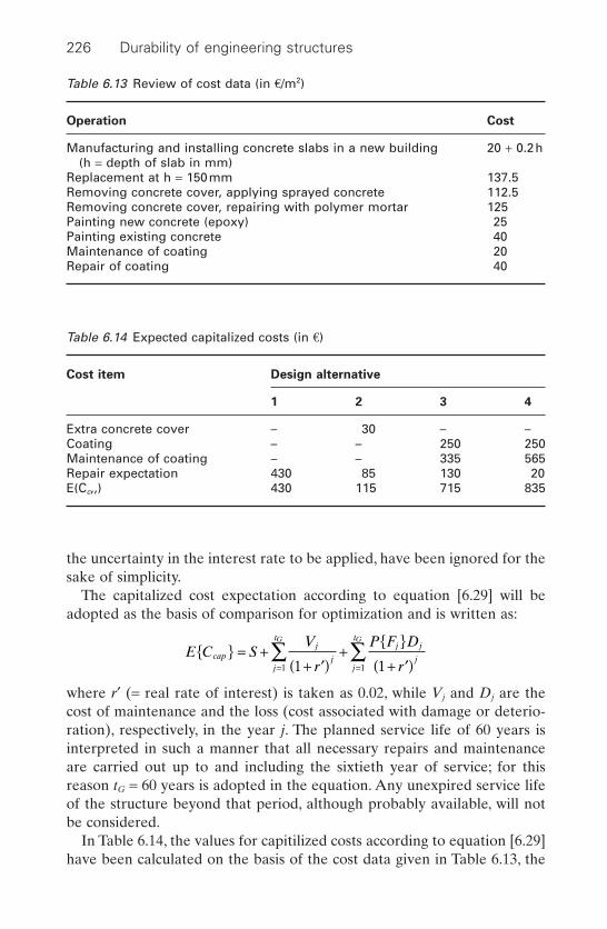
the uncertainty in the interest rate to be applied, have been ignored for thesake of simplicity.
The capitalized cost expectation according to equation [6.29] will beadopted as the basis of comparison for optimization and is written as:
where r¢ (= real rate of interest) is taken as 0.02, while Vj and Dj are thecost of maintenance and the loss (cost associated with damage or deterio-ration), respectively, in the year j. The planned service life of 60 years isinterpreted in such a manner that all necessary repairs and maintenanceare carried out up to and including the sixtieth year of service; for thisreason tG = 60 years is adopted in the equation. Any unexpired service lifeof the structure beyond that period, although probably available, will notbe considered.
In Table 6.14, the values for capitilized costs according to equation [6.29]have been calculated on the basis of the cost data given in Table 6.13, the
E C SV
r
P F D
rcap
j
jj
tj j
jj
tG G
= ++ ¢( )
+
+ ¢( )= =Â Â
1 11 1
226 Durability of engineering structures
Table 6.13 Review of cost data (in €/m2)
Operation Cost
Manufacturing and installing concrete slabs in a new building 20 + 0.2h(h = depth of slab in mm)
Replacement at h = 150mm 137.5Removing concrete cover, applying sprayed concrete 112.5Removing concrete cover, repairing with polymer mortar 125Painting new concrete (epoxy) 25Painting existing concrete 40Maintenance of coating 20Repair of coating 40
Table 6.14 Expected capitalized costs (in €)
Cost item Design alternative
1 2 3 4
Extra concrete cover – 30 – –Coating – – 250 250Maintenance of coating – – 335 565Repair expectation 430 85 130 20E(Cc,,) 430 115 715 835

service life data given in Section 6.5.4.4 and a few additional assumptionsconcerning the extent of deterioration or damage.
The slab is 1.60m wide and 6.30m long, so that its surface area is 10m2.A slab with a 15mm concrete cover, without coating, represents the pointof reference for the cost comparison. For this slab no extra cost is incurredfor increasing durability. For the slab considered as alternative (2), with a30mm cover, a sum of 15 ¥ 0.2 = €3/m2, i.e., a total of €30 per slab, is spenton improving durability. Applying a coating to new concrete costs €25/m2,i.e. €250 for the whole slab. This extra investment occurs also in the alter-natives (3) and (4).
Maintenance is carried out only in the case of these two last-mentionedalternatives. First, consider alternative (4) with maintenance at 10 yearintervals. Maintenance costs €20/m2, i.e., €200 for the slab. The calculationof the capitalized cost of maintenance proceeds as follows:
For alternative (3), it is assumed that maintenance at 20 year intervals will,in 50% of cases carried out, involve repair work costing €400 instead of€200, i.e., €300 on average. Hence the capitalized cost of maintenance is:
The final item to be determined is the loss, i.e. the cost associated withremedying damage or deterioration. In a more or less arbitrary manner,the following possible cost amounts can be distinguished (see also Section 6.5.4):
• Complete replacement: 10 ¥ 137.5 = €1375• Major repairs with sprayed concrete over an area of 4m2: 4 ¥ 112.5 =
€450• Minor repairs with polymer mortar over an area of 2m2: 2 ¥ 125 = €250
As a rule, the loss arising from refurbishment to remedy the effects ofdamage or deterioration will be between €250 and €450. Major repairs orcomplete replacement occur less frequently. In further calculations, anaverage figure of €500 will be adopted for this loss. An exception is theoccurrence of premature damage in the case of alternative (1). If a slab witha 15mm cover and no coating is found to be giving trouble (due to deteri-oration) in a number of places within perhaps a 30 year period, it is evidentthat complete replacement is often likely to offer the most rational remedy.
V
r
j
jj
tG
1
3001 02
3001 02
337 51
20 40+ ¢( )= + =
=Â . .
.€
V
r
j
jj
tG
1
2001 02
2001 02
2001 02
2001 28
2001 49
2001 81
2002 21
2003 69
5 65
110 20 50+ ¢( )
= + + + =
+ + + + + =
=Â . .
. . ..
. . . .. . .
..€
Strategies for durability design, maintenance and repair 227

Otherwise, it is fairly certain that more trouble will occur at other locationsin the slab with time. For alternative (1) and tL < 30 years, the loss is accord-ingly taken as €1000.
To calculate the risk, we must calculate the probability of failure in eachyear. For the sake of convenience, six 10 year periods will be considered:
The probability P(50 < tL < 60) is equal to P(tL < 60–P(tL < 50). All the dataneeded for assessing the risk are thus available. For alternative (1), i.e., a15mm cover and no coating, we obtain:
For the period 0 < tL < 30, the loss has been taken as €1000 and for tL > 30,it has been taken as €500, as explained above. The factors 0.09, 0.25, etc. arethe probabilities of failure in the period 0–10 years, 10–20 years, etc. Thecalculation for the other design alternatives is entirely similar (except that the loss is then €500 for the entire service life). The results are givenin Table 6.14.
Conclusion
By far the most advantageous solution is found to consist in increasing theconcrete cover depth. The direct cost that this entails is low (€30), whiledeterioration or damage occurs only after a long time. To remedy thesedefects, it is often sufficient to carry out relatively simple repairs, while theinterest ensures a substantial decrease in the capitalized cost.
It is notable that applying and maintaining the coating is more expensivethan alternative (1), despite the marked reduction in the probability of dete-rioration or damage. In view of this result, the coating should be appliedprimarily for aesthetic reasons, its protective effect being an additionalbonus.Alternatively, cheaper paints for application to concrete may be usedif the object is simply to improve the appearance of the structure; suchpaints are in general not impermeable to carbon dioxide, however, so thatin this respect they offer little or no protection. An advantage associated
P F D
r
j j
jj
tG + ¢( )
=¥
+¥
+
¥+
¥+
¥+
¥
= + + + + + =
=Â
1
1000 0 091 02
1000 0 251 02
1000 0 291 02
500 0 151 02
500 0 091 02
500 0 041 02
75 168 133 34 16 6 432
110 20
30 40 50 60
..
..
..
..
..
..
€
P F D
r
D
rP t
D
rP t
D
rP t
j j
jj
t
L
L L
G + ¢( )
=+ ¢( )
£ <( ) +
+ ¢( )£ <( ) + +
+ ¢( )£ <( )
=Â
1 10 10
110 20
150 60
1
10
10
20
20
60
60. . .
228 Durability of engineering structures
with the use of protective coatings is the reduced probability of inconve-nience to the residents or users of the building caused by repair work. Thisapplies only to the alternatives requiring frequent maintenance.
6.8.4 Sheet-pile wall alternatives
The Dutch Ministry of Transport, Public Works and Water Management hasmade life-cycle costing calculations concerning seven alternatives for sheet-pile walls to be applied along the Dutch coast for two design service livesof 20 and 50 years, respectively. Five of the alternatives concern steel sheetpiles with various protection systems.The other two are manufactured fromhigh-strength concrete.The walls had to be 13m high, exceeding the highesttidal level by 2m and allowing for a tidal movement of 3m. The sheet pilesare driven into the soil to a depth of 6m.
The following protective measures are considered for the five steel alternatives:
• Organic coating, which should be recoated every 15 years.• Sacrificial steel layer; a layer of steel is allowed to corrode away.• Thermally sprayed aluminium.• Cathodic protection with sacrificial anode (CPSA).• Cathodic protection with impressed current (CPIC).
The protective measures and their capitalized costs are given in Table 6.15.One high-strength concrete concerns a reinforced concrete of strength classC55/67 according to the European concrete standard EN 206-1 Concrete,Specification, Performance and Conformity. The other high-strength con-crete can be referred to as a super high-strength concrete of class C200(beyond the range given in EN 206). The very high strength allows a sub-stantial reduction in thickness of the sheet pile in relation to the C55/67grade, i.e. 240kg/m2 and 560kg/m2, respectively.
The alternative sheet-pile walls considered are:
1 Steel coated, type AZ26 of 155kg steel/m2 of which the coating consistsof 3 layers of a water-borne epoxy system. It is assumed that the steelmust be recoated every 15 years over a length of 7.5m from the top.Recoating must take place below the tidal zone and in the tidal zonealso, which requires the creation of a dry area around the sheet-pile wallduring execution.
2 Steel with a sacrificial steel layer, type AZ36 of 194kg steel/m2. The extrasacrificial thickness of the steel is to suffice for 20 years. A higher thick-ness was not available. For the design service life of 50 years, a 300 mmaluminium layer is thermally sprayed on the steel after a 20 year periodfor the top 5m. (See Section 2.5.4 for protection by metallic coatings.)
Strategies for durability design, maintenance and repair 229
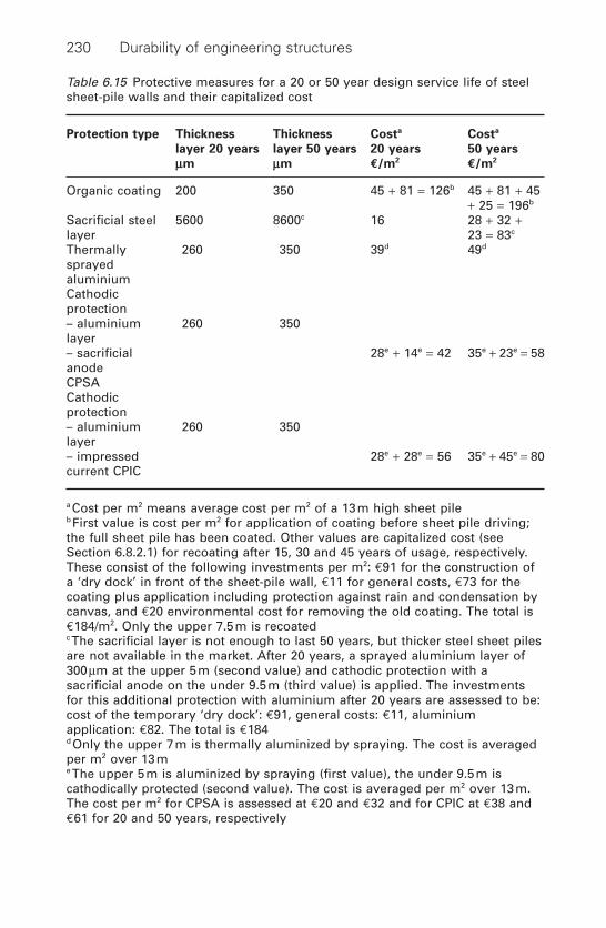
230 Durability of engineering structures
Table 6.15 Protective measures for a 20 or 50 year design service life of steelsheet-pile walls and their capitalized cost
Protection type Thickness Thickness Costa Costa
layer 20 years layer 50 years 20 years 50 years
mm mm €/m2€/m2
Organic coating 200 350 45 + 81 = 126b 45 + 81 + 45+ 25 = 196b
Sacrificial steel 5600 8600c 16 28 + 32 +layer 23 = 83c
Thermally 260 350 39d 49d
sprayedaluminiumCathodicprotection– aluminium 260 350layer– sacrificial 28e + 14e = 42 35e + 23e = 58anodeCPSACathodicprotection– aluminium 260 350layer– impressed 28e + 28e = 56 35e + 45e = 80current CPIC
a Cost per m2 means average cost per m2 of a 13m high sheet pileb First value is cost per m2 for application of coating before sheet pile driving;the full sheet pile has been coated. Other values are capitalized cost (seeSection 6.8.2.1) for recoating after 15, 30 and 45 years of usage, respectively.These consist of the following investments per m2: €91 for the construction ofa ‘dry dock’ in front of the sheet-pile wall, €11 for general costs, €73 for thecoating plus application including protection against rain and condensation bycanvas, and €20 environmental cost for removing the old coating. The total is€184/m2. Only the upper 7.5m is recoatedc The sacrificial layer is not enough to last 50 years, but thicker steel sheet pilesare not available in the market. After 20 years, a sprayed aluminium layer of300mm at the upper 5m (second value) and cathodic protection with asacrificial anode on the under 9.5m (third value) is applied. The investmentsfor this additional protection with aluminium after 20 years are assessed to be:cost of the temporary ‘dry dock’: €91, general costs: €11, aluminiumapplication: €82. The total is €184d Only the upper 7m is thermally aluminized by spraying. The cost is averagedper m2 over 13me The upper 5m is aluminized by spraying (first value), the under 9.5m iscathodically protected (second value). The cost is averaged per m2 over 13m.The cost per m2 for CPSA is assessed at €20 and €32 and for CPIC at €38 and€61 for 20 and 50 years, respectively
Strategies for durability design, maintenance and repair 231
Below these 5m, cathodic protection using a sacrificial anode system(CPSA) is applied (see Section 2.5.5.3).
3 Steel with an aluminium layer on the front surface, with the exceptionof the section embedded in the soil (6m).The thickness of the thermallysprayed aluminium is 260 mm for 20 years and 350mm for the 50 yeardesign service life.
4 Steel with an above-water aluminium layer and underwater cathodic pro-tection with sacrificial (CPSA) anode. Thermally sprayed aluminium forthe upper 5 metres with 260 mm for 20 years and 350mm thickness of thealuminium for the 50 year design service life. Below the upper 5 metres,CPSA is also applied in the soil.
5 Steel with an above-water aluminium layer and underwater cathodic pro-tection with impressed current (CPIC).Thermally sprayed aluminium forthe upper 5 metres with 260 mm for 20 years and 350mm thickness of thealuminium for the 50 year design service life. Below the upper 5 metres,CPIC is also applied in the soil.
6 High-strength concrete C55/67 (EN 206), type A60016C of 560kg/m2.7 Super high-strength concrete C200 of 240kg/m2.
The capitalized costs for the seven alternative sheet-pile walls (see Section6.8.2.1) are given in Table 6.16.The real rate of interest applied is 4%. Figure6.23 shows the total costs.
6.9 Environmental life-cycle assessment
Sustainable development is a key issue in many countries. The Europeanbuilding industry is responsible for about 40% of the total environmentalimpact. Environmental benefits in this industry will, therefore, make a sub-stantial contribution to sustainability. On the basis of the ISO 14040 serieson life-cycle assessment, standards are being developed to assess the envi-ronmental impacts from buildings. Life-cycle costing involves an approachthat covers the whole lifetime. An ISO standard called Sustainability inBuilding Construction – Framework of Assessment of EnvironmentalImpacts from Buildings will be available in the near future. For the build-ing materials and components an ISO standard is being developed calledSustainability in Building Construction – Environmental Product Declara-tion. At the national level, methods have been developed on how to deter-mine environmental impacts of materials, components and buildings inmore detail.
Applying these methods results in environmental impacts and effects.The latter concerns, for instance, the contribution to greenhouse gases,smog, human toxicity and acidification. To simplify the use of those effectsthey are sometimes aggregated to one or a few eco-indicators. These

232 Durability of engineering structures
Table 6.16 Integral capitalized costs of seven alternatives for sheet-pile walls
Sheet-pile alternative Cap. cost in €/m2 Cap. cost in €/m2
20 year service life 50 year service life
Steel-coated 110a + 15b + 126c = 110a + 15b + 196c =251 321
Steel with sacrificial thickness 110a + 16b + 16c = 110a + 16b + 83c =142 209
Steel with aluminium 110a + 15b + 39c = 110a + 15b + 49c =169 174
Steel with above-water aluminium 110a + 15b + 42c = 110a + 15b + 58c =and underwater CPSA 167 183
Steel with above-water aluminium 110a + 15b + 56c = 110a + 15b + 80c =and underwater CPIC 181 205
Concrete C50/67 89a + 36b = 89a + 36b =125 125
Super concrete C200d <278a + 18b = <278a + 18b =<296e <296e
a Cost of steel or concrete sheet-pile without protectionb Cost of sheet-pile drivingc See Table 6.15d A durability assessment over a 50 year period is not really possible at thismomente Material cost for a C200 concrete grade is likely to decrease in future
50 year20 year
350
300
250
200
150
100
50
0
Capitalized cost sheet-pile walls ( /m2)
Ste
el +
add
.ste
el
194/
215k
g/m
2 , afte
r
Ste
el +
Coa
ting
155
kg/m
2
20y
alum
iniu
m +
CP
SA
Ste
el +
alu
min
ium
fron
tsid
e
Ste
el +
alu
min
ium
dry
+ C
PS
A
wet
Ste
el +
alu
min
ium
dry
+ C
PIC
wet
Con
cret
e B
65 5
60
Kg/
m2
Con
cret
e B
200
240
Kg/
m2
6.23 Capitalized costs of seven sheet-pile wall alternatives.
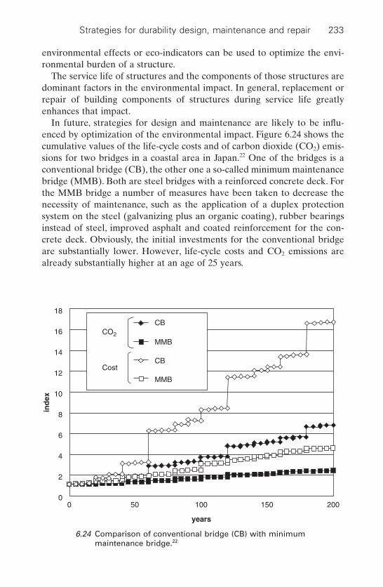
Strategies for durability design, maintenance and repair 233
environmental effects or eco-indicators can be used to optimize the envi-ronmental burden of a structure.
The service life of structures and the components of those structures aredominant factors in the environmental impact. In general, replacement orrepair of building components of structures during service life greatlyenhances that impact.
In future, strategies for design and maintenance are likely to be influ-enced by optimization of the environmental impact. Figure 6.24 shows thecumulative values of the life-cycle costs and of carbon dioxide (CO2) emis-sions for two bridges in a coastal area in Japan.22 One of the bridges is aconventional bridge (CB), the other one a so-called minimum maintenancebridge (MMB). Both are steel bridges with a reinforced concrete deck. Forthe MMB bridge a number of measures have been taken to decrease thenecessity of maintenance, such as the application of a duplex protectionsystem on the steel (galvanizing plus an organic coating), rubber bearingsinstead of steel, improved asphalt and coated reinforcement for the con-crete deck. Obviously, the initial investments for the conventional bridgeare substantially lower. However, life-cycle costs and CO2 emissions arealready substantially higher at an age of 25 years.
CO2
Cost
CB
MMB
CB
MMB
18
16
14
12
10
8
6
4
2
00 50 100 150 200
years
ind
ex
6.24 Comparison of conventional bridge (CB) with minimummaintenance bridge.22
6.10 References
1 Smith D J, Reliability, Maintainability and Risk Oxford, Butterworth-Heinemann, 2001.
2 Discussion Document, Developments in Durability Design and performance-based Specification of Concrete, Concrete Society Special Publication CS 109,Slough, Concrete Society, 1996.
3 Prediction of Service Life of Building Materials and Components, CIB WorkingCommission W80 and RILEM Technical Committee 71-PSL, CIB Report Pub-lication 96, Rotterdam, CIB, 1986.
4 Bakker R F M, Hendriks Ch F, Merkuur Th C, ‘Frost and de-icing salt damageof concrete road decks’, (in Dutch), Wegen, 1982, 790 March 80–9.
5 Bijen J, Montfort J, ‘Cracking of high solids epoxy coatings on steel structuresin the Netherlands’, Materials Performance, 1999 38(5) 46–51.
6 Van Heummen H, Bovée J, van der Zanden J, Bijen J, Materials and Durability,Proceedings Symposium, Saudi Arabia – Bahrain Causeway, Delft, Delft Uni-versity of Technology, 1985.
7 Kraker de A, Tichler J W, Vrouwenvelder A C W M, ‘Safety, reliability andservice life of structures’, Heron, 27(1) 1982.
8 Andrade C, Sarja A, Siemes A J M, Vesikari E, Durability Design of ConcreteStructures, RILEM Report Series 14. London, E & FN Spon, 1996 180–91.
9 Breitenbücher R, Gehlen Chr, Schiessl P, van den Hoonaard J, Siemes T,‘Service life design for the Western Scheldt tunnel, Proceedings 8DBMC, 19993–15.
10 Sitter de W R, Berekening van de levensduur van gewapend beton met het oogop corrosie van de wapening, HBG Report S387 (in Dutch), Rijswijk, HBGRiyswijk, 1982.
11 Vrouwenvelder A C W M, Statistische gegevens t.b.v. het project Veiligheid vanBouw constructies,TNO-IBBC Report No.BI-82-25 (in Dutch),Delft,TNO,1982.
12 Tuutti K, Corrosion of Steel in Concrete CBI Forskring Research f.o. 4.82,Stockholm, Cement och Betong Institute, 1982.
13 Gonzales J, Algaba A S, Andrade C, ‘Corrosion of reinforced bars in carbonatedconcrete’, British Corrosion Journal, 1980 15(3) 12–15.
14 Klopfer H, Anstrichschäden, Wiesbaden, Bauverlag, 1976.15 Sentler L, Service Life Prediction of Concrete Structures, Report TVBK-30 18,
Lund, Lund Institute of Technology, 2001.16 DuraCrete Probabilistic and Performance Based Design Manual for New and
Existing Concrete Structures, Brite/EuRAm project BE95-1347, CURDuraCrete Report R17, Gouda, 1999.
17 Siemes T, Rostam S, ‘Durable safety and serviceability – a performance-basedDesign format’, IABSE Report 74, Proceedings IABSE colloquium Basis ofDesign and Actions on Structures – Background and Application of Eurocode 1,Delft, Zurich, ABSE ETH Hoenggerberg, 1996 41–50.
18 Hergenröder M, Künzel H M, Möller J S, Nilsson L-O, Schiessl P, Siemes T, NewApproach to Durability Design – An example of carbonation-induced corrosion,CEB Bulletin 238, Laussane, CEB, May 1997.
19 Schlaich J, Kordina K, Engell H J, ‘Teileinsturz der Kongresshalle Berlin –Schadenursachen Zusammenfassendes Gutachten’ (in German), Beton undStahlbetonbau, 1980 12 281–94.
234 Durability of engineering structures
20 Raupach M, Dauberschmidt C, ‘Stahlbeton mit Plannmässiger Nutzungsdauervon 100 Jahren (reinforced concrete with a design service life of 100 years),Beton 2002 5 236–42.
21 Peil U, Medhianpour M, Frenz M, ‘Fatigue prediction of steel structures bymeans of monitoring and testing’, in Life-Cycle Cost Analysis and Design of CivilInfrastructure Systems, (eds) Frangopol D M, Furata H, Reston, Virginia,ASCE/SEI, 2001.
22 Itoh, Y, Nagata H, Liu C, Nishikawa K, ‘Comparative study of optimised andconventional bridges: life cycle cost and environmental impact’, Life-Cycle CostAnalysis and Design of Civil Infrastructure Systems’, (eds) Frangopol D M,Furata H, Reston, Virginia, ASCE/SEI, 2001.
Strategies for durability design, maintenance and repair 235
7Case studies
7.1 Introduction
This final chapter discusses three case studies that are typical examples ofpractical problems. For two of these case studies, specification is requestedof the most important requirements that structures have to meet in termsof durability. Durability must then be regarded in relation to reaching theUltimate Limit State and the Serviceability Limit State over the designservice life. This can be extended into other functional requirements, suchas fire safety and energy performance requirements.
In the next section the targets that should be met in writing specificationsare considered because this is an area in which student engineers are oftendeficient.
The case studies discussed are:
• Steel and concrete bridges in a warm marine environment.• Repair of reinforced concrete floors.• Wooden piles.
Disclaimer: The specifications given in this chapter are unsuitable for use without adjustment to the specific environment and the specific structure.
7.2 Specification
7.2.1 Targets
Targets contained in a specification must:
• Relate to a single performance measure of a particular output.• Be expressed in a simple manner.• Specify a time frame or milestone.• Be specified for each measure selected.
236
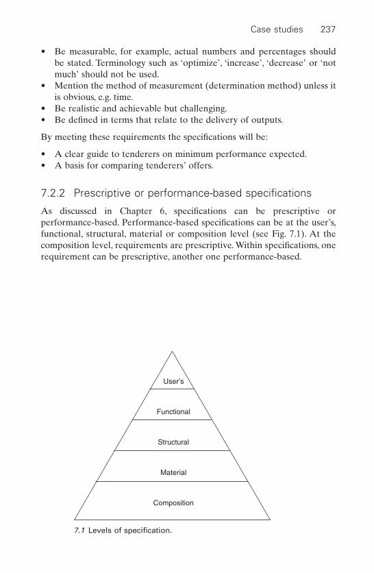
Case studies 237
• Be measurable, for example, actual numbers and percentages should be stated. Terminology such as ‘optimize’, ‘increase’, ‘decrease’ or ‘notmuch’ should not be used.
• Mention the method of measurement (determination method) unless itis obvious, e.g. time.
• Be realistic and achievable but challenging.• Be defined in terms that relate to the delivery of outputs.
By meeting these requirements the specifications will be:
• A clear guide to tenderers on minimum performance expected.• A basis for comparing tenderers’ offers.
7.2.2 Prescriptive or performance-based specifications
As discussed in Chapter 6, specifications can be prescriptive or performance-based. Performance-based specifications can be at the user’s,functional, structural, material or composition level (see Fig. 7.1). At thecomposition level, requirements are prescriptive. Within specifications, onerequirement can be prescriptive, another one performance-based.
User’s
Functional
Structural
Material
Composition
7.1 Levels of specification.

238 Durability of engineering structures
7.3 Case study 1: steel and concrete bridges in a
warm marine environment
7.3.1 Description, problem definition and instructions
Two bridges must be designed; they span creeks on the coast of Mumbai(Bombay) in India. One is a cable-suspended bridge and the other a can-tilever bridge. In the suspension bridge, the pylons are manufactured fromreinforced concrete and the bridge deck is made of steel. The cantileverbridge will be manufactured from prefabricated concrete segments of whichthe hollow piers and the superstructure are post-tensioned (it is a post-tensioned precast segmental bridge). The bridges should have a service lifeof 75 years without corrective (essential) maintenance.
Note: The aim of this case study is to draft material specifications concern-ing durability/service life of these bridges, as well as the maintenancerequired over a 75-year period.
Specific points are:
• To describe the relevant deterioration mechanisms.• To write specifications for the following bridge components:
– Cable-suspended: the concrete pylons, the suspension cables andthe steel bridge-deck;
– Cantilever: the piers and the superstructure.• To specify required maintenance (frequency, type) for the steel bridge
deck.
7.3.2 Relevant deterioration mechanisms
7.3.2.1 Exposure conditions
The exposure conditions of the bridges should be known so as to determinethe relevant deterioration conditions. The climate of Mumbai can be char-acterized as a warm marine environment. It is warm and humid all yearround; temperatures are relatively stable due to the moderating influenceof the sea.
Because of the position of the bridges along the coast, we can assumethat chloride loading will be high, drying-out of concrete will be limited andair pollution will be low.
7.3.2.2 Concrete: pylons, cantilever bridge
Based on Chapter 3 ‘Concrete’, the following mechanisms are relevant tothe concrete parts of the structures:
Case studies 239
• Chloride-initiated corrosion of reinforcement in concrete in tidal,splash, spray and atmospheric zones (see Section 3.4.3).
• Salt weathering (see Section 3.2.3.4). It should be noted that due to gen-erally high humidity, deterioration will be less than in warm arid marineclimates, such as along the Gulf.
Attention should be paid to:
• Alkali–silica attack; however, this is only relevant if alkali-reactiveaggregates are applied.
Not relevant are:
• Carbonation, because of high humidity.• Sulphate expansion, because the sulphate salts formed in a marine envi-
ronment, like ettringite, are non-expansive (see Section 3.2.3.1).
7.3.2.3 Post-tensioning tendons
For discussion on stress corrosion of post-tensioned tendons in the can-tilever bridge see Section 3.4.8. Corrosion of tendons in post-tensionedprecast segmental bridges is generally due to:
• Voids present within the grout used to fill the tendon ducts and protectthe prestressing steel. Inadequate grouting may allow water to penetrateinto the ducts, initiate corrosion of the tendons and potentially lead tofailure of the structure.
• Failing corrosion protection of tendons where they pass through thebridge segment joints. For these joints, match-cast epoxy is usuallyapplied.
Although global experience has been highly positive, a number of fail-ures have been known to happen. Thus in the UK for instance, there wasthe sudden collapse of the Bickton Meadows footbridge in 1967 and of theYnys-y-Gwas Bridge in 1985 due to corrosion of tendons. This, in additionto other documented problems with post-tensioned bridges led to a ban in1992 on the construction of new bonded post-tensioned bridges by the UKMinistry of Transport. In 1996, the moratorium on grouted post-tensionedcast-in-place construction was lifted, but remains in force for segmentalconstruction.1
7.3.2.4 Steel bridge deck
The following deterioration mechanisms should be taken into account (theyare based on the discussion in Chapter 2):
240 Durability of engineering structures
• Corrosion fatigue (see Section 2.3.2.12). This is by far the most fre-quently occurring problem in steel bridge decks.
• Uniform corrosion in unprotected steel (see Section 2.3.1).• Pit corrosion can occur in the case of non-conductive protective layers,
such as organic coatings (see Section 2.3.2.4).
7.3.2.5 Suspension stay cables
The following deterioration mechanisms are relevant (they are based onthe discussion in Chapter 2)
• Stress corrosion (see Section 2.3.2.10).• Hydrogen embrittlement (see Section 2.3.2.11).
7.3.3 Specifications for durability
7.3.3.1 Concrete: pylons, cantilever bridge
Prescriptive
Prescriptive specifications for the concrete in pylon and cantilever bridgesis given in Table 7.1. In this specification, the contractor has only to makesure that the requirements are met in practice. If the specifications appearto be insufficient to safeguard durability, the designer is responsible.
NB: Possible legal action to claim indemnity from either designer or con-tractor greatly differs between countries.
Note: For concrete bridge decks in many countries polymer or bituminousmembranes are applied beneath the bituminous asphalt to protect the con-crete against ingress of chlorides. In the case of concrete meeting the spec-ifications of Table 7.1 this measure is not required. In the Netherlands theMinistry of Transport, Public Works and Water Management sometimesprescribes treatment with a hydrophobic agent of the concrete surfacebefore applying the asphalt top.3
Performance
A simple requirement at the user’s level can be: ‘The service life of the concrete structure must be 75 years. In this period, no major maintenance/repair will be required.’ In this case, the design for durabilityis left to the contractor, who will be held responsible if the requirement isnot met in practice.
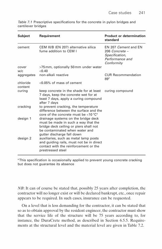
Case studies 241
NB: It can of course be stated that, possibly 25 years after completion, thecontractor will no longer exist or will be declared bankrupt, etc., once repairappears to be required. In such cases, insurance can be requested.
On a level that is less demanding for the contractor, it can be stated thatso as to obtain approval by the resident engineer, the contractor must showthat the service life of the structure will be 75 years according to, forinstance, the DuraCrete method, as described in Section 6.5.5. Require-ments at the structural level and the material level are given in Table 7.2.
Table 7.1 Prescriptive specifications for the concrete in pylon bridges andcantilever bridges
Subject Requirement Product or determination
standard
cement CEM III/B (EN 207) alternative silica EN 207 Cement and ENfume addition to CEM I 206 Concrete –
Specification, Performance andConformity
cover >75mm, optionally 50mm under waterw/c <0.40aggregates non-alkali reactive CUR Recommendation
892
chloride <0.05% of mass of cementcontentcuring keep concrete in the shade for at least curing compound
7 days, keep the concrete wet for at least 7 days, apply a curing compound after 7 days
cracking to prevent cracking, the temperaturedifference between the surface and thecore of the concrete must be <10 °Ca
design 1 drainage systems on the bridge deck must be made in such a way that the bridge deck ceiling or piers shall not be contaminated when water and gutter discharge fall down
design 2 auxiliaries, such as metal lamp posts and guiding rails, must not be in direct contact with the reinforcement or the prestressed steel
a This specification is occasionally applied to prevent young concrete crackingbut does not guarantee its absence

242 Durability of engineering structures
Not recommended
The following measures must not be selected:
• Sulphate-resistant Portland cement: this cement shows rapid chloridepenetration, whereas there is no sulphate attack (see Section 3.4.3.2).
• Cover ≥100mm: there is no need for it and a thicker concrete covermeans more weight and will make it more difficult to prevent cracking.
• Cover £50mm: this thickness will be critical, especially when vulnera-bility for curing is taken into account; 10mm of the cover can be ‘lost’easily due to poor curing.
• Coating on concrete: it will deteriorate rapidly and is not necessary (seeSection 3.8.4.3).
• Coated rebars: not reliable (see Section 3.4.7.5).• Stainless steel rebars: not necessary and expensive.
7.3.3.2 Cantilever bridge prestressing tendons
Prescriptive
• The prestressing steel should be delivered packaged in a waterproofwrapping. The package should include a siccative or a vapour-basedinhibitor.
• Apply high-density polyethylene (HDPE) or polypropylene corrugatedducts according to References 3 and 4.
Table 7.2 Performance specifications for the concrete in pylon bridges andcantilever bridges
Subject Requirement Product or determination
standard
chloride penetration charge (coulomb) ASTM C1202 ‘electrical (of the concrete of £1000 indication of concrete’s ability tothe structure) resist chloride penetration’cover >75mm, optionally
50mm under wateraggregates non-alkali reactive CUR Recommendation 89a
chloride content <0.05% of mass ofcement
cracking cracking of youngconcrete is notallowed
a Reference 2

Case studies 243
• Contact between the environment and cables during the constructionstage is not allowed. This should be achieved by applying a protectivegas, e.g. nitrogen.
• Grouts should fully embed the tendons.• Composition of the grouts:
– W/C grout <0.35;– Portland cement with silica fume (8% of mass of cement);– non-bleeding (segregation and separation of water is not allowed).
• Box-outs at tendon anchoring should be especially attended to with aview to chloride penetration, e.g. by coating the steel parts of the anchor-ing system and by applying epoxy bonding agents between the concrete,steel and the box-fill-in.
Reference can be made to the AASHTO Standard Specifications forHighway Bridges. Precast segmental bridges also fall under the jurisdictionof the AASHTO Guide Specifications for Design and Construction of Segmental Concrete Bridges. For grouting, reference can be made to theRecommended Practice for Grouting of Post-tensioned Prestressed Concreteof the Post-Tensioning Institute (PTI). Alternatively, reference can be made to FIP recommendations5 and guidelines.6
7.3.3.3 Steel bridge deck
Prescriptive
The protection system specified in Table 7.3 can be applied to the steel. Atypical protection system applied in the Netherlands applied on steel bridgedecks with heavy traffic is shown in Fig. 7.2 and specifications are given inTable 7.4.7
Performance
As for the concrete pylons and cantilever bridge, a performance specifica-tion can be at a functional level. The following is the author’s proposedspecification: ‘The coating system will show no failures within 15 years,unless caused by accidents. Maintenance after 15 years will be restricted tothe application of a new topcoat. Full recoating will not be required beforea 30 year period has passed’.
More definitive is the specification method used by the Dutch Ministryof Transport, Public Works and Water Management, as discussed in Section6.4.2.2, which includes:
• Proven performance in practice.• Surviving representative accelerated ageing without damage, such as
cracks and blisters.
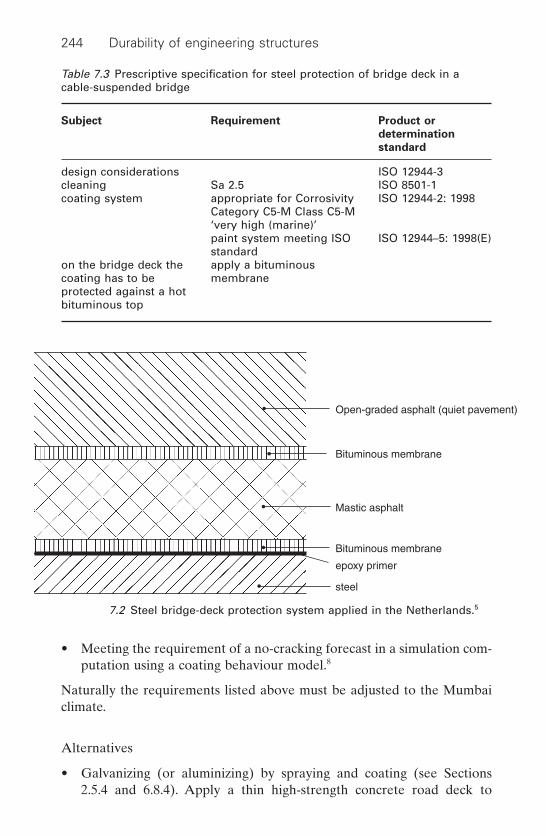
244 Durability of engineering structures
• Meeting the requirement of a no-cracking forecast in a simulation com-putation using a coating behaviour model.8
Naturally the requirements listed above must be adjusted to the Mumbaiclimate.
Alternatives
• Galvanizing (or aluminizing) by spraying and coating (see Sections 2.5.4 and 6.8.4). Apply a thin high-strength concrete road deck to
Table 7.3 Prescriptive specification for steel protection of bridge deck in acable-suspended bridge
Subject Requirement Product or
determination
standard
design considerations ISO 12944-3cleaning Sa 2.5 ISO 8501-1coating system appropriate for Corrosivity ISO 12944-2: 1998
Category C5-M Class C5-M ‘very high (marine)’paint system meeting ISO ISO 12944–5: 1998(E)standard
on the bridge deck the apply a bituminous coating has to be membraneprotected against a hotbituminous top
Open-graded asphalt (quiet pavement)
Bituminous membrane
Bituminous membrane
Mastic asphalt
epoxy primer
steel
7.2 Steel bridge-deck protection system applied in the Netherlands.5
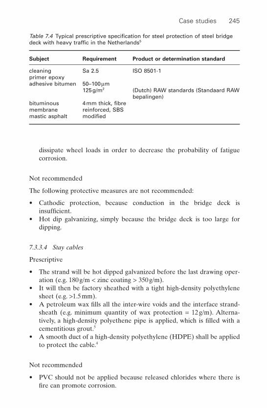
Case studies 245
dissipate wheel loads in order to decrease the probability of fatigue corrosion.
Not recommended
The following protective measures are not recommended:
• Cathodic protection, because conduction in the bridge deck is insufficient.
• Hot dip galvanizing, simply because the bridge deck is too large fordipping.
7.3.3.4 Stay cables
Prescriptive
• The strand will be hot dipped galvanized before the last drawing oper-ation (e.g. 180g/m < zinc coating > 350g/m).
• It will then be factory sheathed with a tight high-density polyethylenesheet (e.g. >1.5mm).
• A petroleum wax fills all the inter-wire voids and the interface strand-sheath (e.g. minimum quantity of wax protection = 12g/m). Alterna-tively, a high-density polyethene pipe is applied, which is filled with acementitious grout.5
• A smooth duct of a high-density polyethylene (HDPE) shall be appliedto protect the cable.4
Not recommended
• PVC should not be applied because released chlorides where there isfire can promote corrosion.
Table 7.4 Typical prescriptive specification for steel protection of steel bridgedeck with heavy traffic in the Netherlands5
Subject Requirement Product or determination standard
cleaning Sa 2.5 ISO 8501-1primer epoxyadhesive bitumen 50–100mm
125g/m2 (Dutch) RAW standards (Standaard RAWbepalingen)
bituminous 4mm thick, fibremembrane reinforced, SBSmastic asphalt modified
246 Durability of engineering structures
• Cathodic protection is not an option due to failing conductance,although galvanizing provides a kind of cathodic protection.
7.3.4 Maintenance
7.3.4.1 Concrete structures
Although concrete is designed in such a way that preventive or correctivemaintenance should not be necessary, it is, naturally, unwise to refrain fromany inspection because errors could have been made in both the design andexecution of the works. It is generally recommended to carry out a visualinspection, once a year in the first two years and once every two years afterthat. If any defect is observed, it should be examined in greater depth. Ifthe frequency of defects increases, the inspection rate should be increased(see discussion on ‘the bath-tub curve’ in Section 6.7.4). Vulnerable parts,such as expansion joints and the applied expansion joint bridging systems,must be inspected each year. If there are defects in the system, e.g. failingmoving parts, action must be taken (applying new grease or replacingparts). Bearing plates also need yearly inspections.
7.3.4.2 Steel bridge deck
• Stresses and strains in the bridge deck should be monitored regularly.This can be done continuously by applying strain gauges. Stresses andstrains should stay within the serviceability limit state.
• Visual inspection of defects in the applied coating system; frequently inthe first year and once a year after that.
7.4 Repair of reinforced concrete floors
7.4.1 Description, problem definition and questions
Part 1
A structural engineer and concrete maintenance expert are requested toinvestigate the ground floor of a school. The floor is a Kwaaitaal floor.A preliminary inspection by the maintenance department of the school has disclosed that there is corrosion of reinforcement. A procedure is to be drafted to investigate the damage and make a diagnosis based on theinvestigation.

Case studies 247
Part 2
Following the investigation, it is concluded that neither structural safety norserviceability is endangered within a 10 year period, but beyond that periodthis state is no longer warranted because of the ongoing corrosion process.However, the school has to be in service for a minimum period of 25 years.The possibilities to safeguard the structural safety and serviceability over aperiod of at least 25 years will be discussed and a motivated choice madebetween two methods.
7.4.2 Background
Kwaaitaal precast reinforced concrete floors were manufactured in theNetherlands between 1965 and 1982. A typical cross-section of the floorwith the damage observed is given in Fig. 7.3. A typical precast floorsegment consists of two ribs. Calcium chloride was mixed into the concreteto accelerate cement hardening. The main problem was that the calciumchloride was applied in the form of flakes, which did not mix in well, leadingto a very inhomogeneous chloride distribution throughout the concrete.This differential concentration has caused a highly corrosive situation.Typical corrosion phenomena are shown in Fig. 7.4. Because the Kwaaitaalprecast floors and a competitive system called Manta, with the sameproblem, had been used on a massive scale in dwellings, schools and super-markets, the size of damage was substantial. This prompted the Dutch government to investigate the problem in depth. The results are given inReferences 9 and 10.
Rust Cracks Concrete cover
7.3 Cross-section of Kwaaitaal floor with type of damage observed.

248 Durability of engineering structures
7.4 Photographs of damage of Kwaaitaal floors in crawl space.
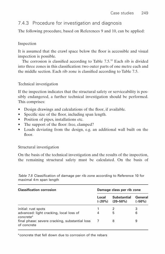
Case studies 249
7.4.3 Procedure for investigation and diagnosis
The following procedure, based on References 9 and 10, can be applied:
Inspection
It is assumed that the crawl space below the floor is accessible and visualinspection is possible.
The corrosion is classified according to Table 7.5.10 Each rib is dividedinto three zones in this classification: two outer parts of one metre each andthe middle section. Each rib zone is classified according to Table 7.5.
Technical investigation
If the inspection indicates that the structural safety or serviceability is pos-sibly endangered, a further technical investigation should be performed.This comprises:
• Design drawings and calculations of the floor, if available.• Specific size of the floor, including span length.• Position of pipes, installations etc.• The support of the floor: free, clamped?• Loads deviating from the design, e.g. an additional wall built on the
floor.
Structural investigation
On the basis of the technical investigation and the results of the inspection,the remaining structural safety must be calculated. On the basis of
Table 7.5 Classification of damage per rib zone according to Reference 10 formaximal 4m span length
Classification corrosion Damage class per rib zone
Local Substantial General
(<20%) (20–50%) (>50%)
initial: rust spots 1 2 3advanced: light cracking, local loss of 4 5 6concretea
final phase: severe cracking, substantial loss 7 8 9of concrete
a concrete that fell down due to corrosion of the rebars

250 Durability of engineering structures
structural calculations on Kwaaitaal floors with a span not exceeding 4m,as given in References 9 and 10, the structural damage can be classified asa rule of thumb assessment using the classification given in Table 7.6.
7.4.4 Possibilities to extend the service life by 25 years
From the investigation described in the previous section, it is concluded that expectations are that the floor is still structurally safe and that the serviceability during a ten year period will not be endangered. However,it is expected that beyond the ten year period, this will no longer be thecase.
Note: In making this conclusion it is assumed that the environmental con-ditions, notably humidity, in the crawl space will not change.
However, the school has to be in service for another 25 years. Within tenyears, therefore, remedial action (preventive, reactive maintenance) will berequired. There are several methods to extend the service life. They aredetailed below.
Replacement
Replacing the ground floor by a new floor (Method 3.4, Table 3.6). Obvi-ously, the ground floor will be out of operation during this operation.
Table 7.6 Classification of damage and time span of action
Classification of damage Time span of
action required
• in fields of six adjacent ribs:– An average decrease of the rebar cross- immediate
section of more than 15%– Two or more adjacent ribs: damage class 7–9 immediate
and load-bearing capacity <30%:• three adjacent ribs with class 7–9 and remaining load immediate
capacity 30–60%• one of the outer floor fields (two ribs) shows damage immediate
class 7–9• floor with ribs of a damage class not exceeding 4–6 within 5 to 10
years • floor with ribs of a damage class not exceeding 1–3 no time
limit, regularinspections

Case studies 251
Structural strengthening methods
• Placing prestressing tendons underneath the floor elements and post-tensioning them (Method 4.7, Table 3.6), see Fig. 7.5. The tendons areprestressed at the school walls above the foundations and sometimesthese foundations have to be reinforced. The walls act as a rim beam forthe tensioning.
• Placing support beams (steel, aluminium, wood) underneath the floor.The beams are supported by making holes in the walls under the floor.
• Placing support beams in the crawl space on specially manufacturedfoundations.
7.5 Prestressing tendons underneath Kwaaitaal floor.
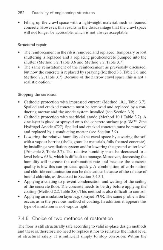
252 Durability of engineering structures
• Filling up the crawl space with a lightweight material, such as foamedconcrete. However, this results in the disadvantage that the crawl spacewill not longer be accessible, which is not always acceptable.
Structural repair
• The reinforcement in the rib is removed and replaced.Temporary or lostshuttering is replaced and a replacing grout/concrete pumped into theshutter (Method 3.2, Table 3.6 and Method 7.2, Table 3.7).
• The same reinstatement of the reinforcement as previously discussed,but now the concrete is replaced by spraying (Method 3.3,Table 3.6. andMethod 7.2, Table 3.7). Because of the narrow crawl space, this is not arealistic option.
Stopping the corrosion
• Cathodic protection with impressed current (Method 10.1, Table 3.7).Spalled and cracked concrete must be removed and replaced by a con-ducting mortar and the anode system installed (see Section 3.9).
• Cathodic protection with sacrificial anode (Method 10.1 Table 3.7). Azinc layer is glued or sprayed onto the concrete surface (e.g. 3MTM ZincHydrogel Anode 4727). Spalled and cracked concrete must be removedand replaced by a conducting mortar (see Section 3.9).
• Lowering the relative humidity of the crawl space by covering the soilwith a vapour barrier (shells, granular materials, foils, foamed concrete),by installing a ventilation system and/or lowering the ground water level(Principle 8, Table 3.7). The relative humidity must be decreased to alevel below 65%, which is difficult to manage. Moreover, decreasing thehumidity will increase the carbonation rate and because the concretequality is low this can proceed quickly. A combination of carbonationand chloride contamination can be deleterious because of the release ofbound chloride, as discussed in Section 3.4.3.1.
• Applying a coating to prevent condensation and wetting of the ceilingof the concrete floor. The concrete needs to be dry before applying thecoating (Method 2.2, Table 3.6). This method is also difficult to control.
• Applying an insulation layer, e.g. sprayed PUR. The same problem thenoccurs as in the previous method of coating. In addition, it appears thistype of insulation is not vapour tight.
7.4.5 Choice of two methods of restoration
The floor is still structurally safe according to valid in-place design methodsand there is, therefore, no need to replace it nor to reinstate the initial levelof structural safety. It is sufficient simply to stop corrosion. Within the

Case studies 253
methods to stop corrosion, as discussed in the previous section, cathodicprotection is the most reliable. Removing spalled and cracked concrete andreplacing it with a well-conducting cementitious mortar and subsequentlygluing a sacrificial zinc foil anode over the ribs is the simplest method toapply in the narrow crawl space (see Fig. 7.6.). However, there are somedoubts with respect to the application and the durability of cathodic pro-tection for this case. Removing and replacing of concrete in the narrowcrawl space is difficult. There is no long term experience with the durabil-ity of the adhesive of the zinc foil and the effect of possible changes inhumidity are not known. Therefore, in the Netherlands, structural strength-ening is usually the preferred option. This does not stop corrosion, but pro-vides another load-bearing capacity that can replace the function of therebars in the Kwaaitaal floors.
The method of prestressing tendons is frequently applied in the Nether-lands. The tendons are applied parabolically; they give an upward force onthe floor that compensates the load. Points to which attention should bepaid are:
• The loads in combination with the tension on the tendons should notcause too high tension stress in the walls (rim beams).
• Upward stresses due to the tensioning system should be counterbal-anced by the floor load.
• The ends of the floor elements should be well-clamped structurally.• Cold transportation can occur at the joint of the floor and the outer wall
of the school, where the tendons are anchored.
7.5 Wooden piles
7.5.1 Description, problem definition and questions
A housing corporation requests wooden foundation piles to be used withinthe framework of sustainable building. However, during the last few years
Junction Box
Zinc connectorZincAdhesive
Electricalconnection
Rebar
7.6 Zinc foil with glue and conducting layer (courtesy 3MTM).
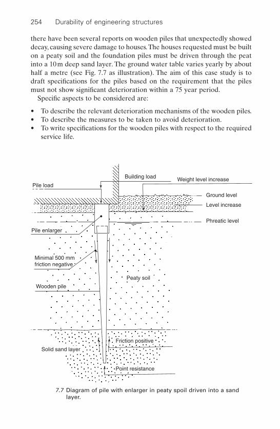
254 Durability of engineering structures
there have been several reports on wooden piles that unexpectedly showeddecay, causing severe damage to houses.The houses requested must be builton a peaty soil and the foundation piles must be driven through the peatinto a 10m deep sand layer. The ground water table varies yearly by abouthalf a metre (see Fig. 7.7 as illustration). The aim of this case study is todraft specifications for the piles based on the requirement that the pilesmust not show significant deterioration within a 75 year period.
Specific aspects to be considered are:
• To describe the relevant deterioration mechanisms of the wooden piles.• To describe the measures to be taken to avoid deterioration.• To write specifications for the wooden piles with respect to the required
service life.
Pile load
Phreatic level
Level increase
Ground level
Weight level increaseBuilding load
Pile enlarger
Minimal 500 mmfriction negative
Wooden pile
Solid sand layer
Point resistance
Friction positive
Peaty soil
7.7 Diagram of pile with enlarger in peaty spoil driven into a sandlayer.
Case studies 255
7.5.2 Relevant deterioration mechanisms
Relevant deterioration mechanisms are:
• Decay by fungi (see Section 4.2.1). However, beneath the lowest watertable, the piles will not be affected.
• Attack by bacteria (see Section 4.2.4). In general, this is a slow process,but this deterioration process can occur even below the water table and,depending on the wood species, can cause serious problems.These prob-lems are observed in the sapwood of Scotch fir (Pinus sylvestris)(French: sapin ecossaise, German: Scottische Tanne, Dutch: grenen) inparticular.
7.5.3 Prevention measures
• Attack by fungi can be avoided by applying the wood below the watertable only. In the Dutch standard NEN 6711, Article 6.2, it is prescribedthat the top of the wooden pile should be at least 400mm below thelowest ground water table. In practice, designers usually situate it at 500mm below.
In general, a concrete pile-enlarger (Dutch: oplanger) is applied ontop of the wooden pile, which bridges the zone with the fluctuating watertable (see Fig. 7.8). Alternatively, wooden enlargers of Durability Class1 or 2 according to EN 350 (Table 4.2.) can also be applied
• To avoid deterioration by bacteria, the following wood species appearedto be resistant, provided the sapwood content is minimized:– Norway spruce (Picea abies) (French: epicea, German: Fichte,
Dutch: vuren);– Japanese larch (Larix leptolepis), (French: mélèze, German: Lärche,
Dutch: lariks);– Douglas fir (Pseudotsuga menziesii);
• Alternatively, modified wood can also be applied, if available (currentlynot available at pile length) (see Section 4.3.5).
Not recommended
Not to be applied are:
• Painted wood or wood treated with water-repellents, because of damageduring pile driving.
• Wood protected with oily preservatives, such as creosote or water-bornetoxic salts, because the request specified sustainability and, moreover, itis not necessary.
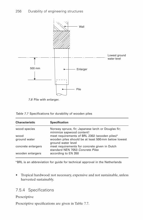
256 Durability of engineering structures
• Tropical hardwood: not necessary, expensive and not sustainable, unlessharvested sustainably.
7.5.4 Specifications
Prescriptive
Prescriptive specifications are given in Table 7.7.
500 mm
Pile
Enlarger
Lowest groundwater level
Wall
7.8 Pile with enlarger.
Table 7.7 Specifications for durability of wooden piles
Characteristic Specification
wood species Norway spruce, fir; Japanese larch or Douglas fir;minimize sapwood content!
wood meet requirements of BRL 2302 (wooden piles)a
ground water wooden piles should be at least 500mm below lowestground water level
concrete enlargers meet requirements for concrete given in Dutchstandard NEN 7053 Concrete Piles
wooden enlargers according to EN 350
a BRL is an abbreviation for guide for technical approval in the Netherlands

Case studies 257
7.6 References
1 Durability of Precast Segmental Bridge, Final Report, NHCRP web document15, 1998.
2 Measures to Prevent Damage Due to Alkali–Silica Reaction, CUR Recommen-dation 89 (in Dutch) Gouda, 2002.
3 Durable Bonded Post-Tensioned Concrete Bridges, Technical Report No 47,Slough, The Concrete Society, 1996.
4 Corrugated Plastic Ducts for Internal Bonded Post-tensioning, bulletin 7,Lausanne, Fib, 2000.
5 ‘Corrosion Protection of Prestressing Steel’, Recommendation, Lausanne, FIP,September 1996.
6 ‘Preparation of Specifications of Post Tensioning Work’, Guide to Practice,Lausanne, FIP, October 1992.
7 Manual of Civil Engineering Structures, (in Dutch), The Hague, Netherlands, tenHagenStam publishers, 1999.
8 Bijen J, Montfort J, ‘Cracking of high solids epoxy coatings on steel structuresin the Netherlands’, Materials Performance, 1999 38(5) 46–51.
9 Damage of Concrete Floors of Kwaaitaal and Manta in Dwellings, CUR Report2000-1 (in Dutch), Gouda, 2000.
10 Assessment of Kwaaitaal and Manta Ground Floors, CUR Recommendation 79(in Dutch), Gouda, 2001.

cable suspended/ stayed bridge, 91, 238–46calcium carbonate, 60, 64, 65calcium chloride, 81, 247calcium nitrite, 90capitalising cost, 218–31carbonation, 15, 65, 74, 77–80, 87, 89, 92, 93,
98, 100, 167, 188, 189, 198–209, 209–22,239, 252
corrosion, 15, 77–80, 87, 89, 92, 93, 98–100,167, 188, 189, 198–209, 239, 252
frost-thaw de-icing salt resistance, 74modelling, 79repair, 98–100, 222–9thaumasite, 65
carbon dioxide/CO2, 58, 77, 98, 198, 201, 210,222, 228, 233
cast iron, 29, 30, 32cathodic control, 101, 102cathodic protection, 14, 20, 28, 26, 46, 48–53,
86, 102, 123–9, 133, 134–6, 175, 192, 217,229, 230, 245, 252, 253
anodes, 124–8, 136criteria, 50–2, 123–9, 136hydrogen embrittlement, 20, 46, 128impressed current, 50–2, 123–9, 136repair, 134–6, 175, 252, 253sacrificial, 50, 127, 229, 230stray current, 86
cathodic reaction, 5, 15, 21, 22, 30cellulose, 140, 141, 146cement, 66, 70, 71, 74, 77, 80, 85, 88, 89, 130,
133, 159, 167, 241, 242CEM I Portland Cement, 66, 70, 74, 77,
89CEM III Blast Furnace Slag Cement, 63,
64, 66, 70, 74, 80, 88, 133, 159, 167, 241CEM II Portland fly ash cement, 70, 71,
74, 80low alkali Portland cement, 70sulphate resistant Portland cement, 85,
130, 242chalcedony, 69
Index
abrasion, 146, 165air content, 75air-entrainment, 75–7, 163alkali silica reaction, 55, 64, 68–71, 96, 129,
164, 239alkaline attack, 146, 172, 176alkylalkoxy silanes, 118–24aluminium, 3, 18, 20, 21, 23, 26, 40, 251
aluminising, 244anodising, 36, 40spraying, 45, 48
ammonium bifluoride pills, 148, 156ammonium, 61, 62, 148anchorage, 91–3anodes, 124–8, 136anodic reaction, 5, 20, 126
bacterial attack, 146bathtub curve, 216beetles, 143–5, 153–5binders, 40–2, 88, 89, 104, 107, 117, 122biological attack, 139, 148, 150, 151, 154biological decay, 24, 141–7, 153–5, 255
fungi, 24, 141–3, 147, 155, 255insects, 144–5, 155marine borers, 145, 153, 154bacteria, 146, 255
blast furnace slag cement, 63, 64, 66, 70, 74,80, 88, 133, 159, 167, 241
bleeding, 93, 162, 166, 243blistering, 60, 64, 75, 118, 171, 190bridges, 27, 75, 84, 85, 91, 114, 124, 125, 147,
158, 161,165, 168, 173, 191, 215, 217, 233bearing plates, 217, 246cable suspended/stayed, 91, 238–46cathodic protection, 124, 125concrete, 75, 84, 85, 114, 124, 125, 165, 191,
238–46FRP, 173steel, 27, 161, 162, 215, 233, 238–46wood, 147
brown rot, 142
258

Index 259
chemical degradation mechanisms,55–68, 118, 126, 127, 146, 148, 172, 239,242
acid rain, 60acids, 55–61, 126, 127, 146, 148, 172aggressive water, 60alkaline, 172biogenic sulphuric attack, 55–9, 118manure silos, 59organic acid, 60–1salts, 55, 61–3salt weathering, 68, 239seawater, 65sewage water, 55–9, 118sulphate attack, 63–8, 242
cleaning, 37–9chloride, 29, 35, 54, 80–6, 87, 90. 93, 94, 98,
130, 131, 134, 161, 163, 167, 174, 196,100–1, 216, 218, 239, 240, 242, 243
aluminium, 35corrosivity, 29extraction, 100–1ingress, 80–6, 93, 94, 98, 130, 131, 161, 163,
167, 174, 196, 216, 240, 242, 243initiated corrosion, 54, 87, 90, 134, 163,
218, 239mixed-in, 131, 247penetration, 80–6, 93, 94, 98, 130, 131, 161,
163, 167, 174, 196, 216, 240, 242, 243coating, 37–43, 60, 64, 75, 90, 91,100, 103,
104, 107, 115–17, 122, 123, 126, 131,133, 136, 148, 149, 216, 225–8, 229–30,255
barrier, 100, 103, 131binder, 40–2, 104, 107, 117, 122blistering, 60, 64, 75, 118, 171, 190cleaning, 37–9, 40, 43, 131, 133conductive, 126, 136cost, 225–9epoxy, 41, 43, 90, 107, 11, 118, 122, 123,
131, 133, 201, 216, 229–30epoxy high built, 41, 43, 90, 107, 122,
216inorganic, 42metallic, 45–8organic, 40–5passive, 28, 45pigments, 40–1, 102–3, 122, 149powder, 40, 41, 90, 91surface preparation, 37–9tar-epoxy, 123, 190thermal compatibility, 115–17transition temperature, 116wood, 148–9, 255
conductive coating, 126, 136corrective maintenance, 159, 183, 214–17,
246corrosion critical concentration, 81, 89, 134,
211
corrosion environment, 29, 30, 168, 239atmospheric, 29, 168, 239underground, 30under water, 30
corrosion inhibitors, 10, 90, 103corrosion mechanisms, 4–6corrosion potential (mixed), 6–9corrosion propagation, 86–7, 210corrosion rate, 7–9, 100, 101, 175, 200, 205corrosion types, 13, 15–28, 30, 33, 35, 36, 42,
87, 90, 91, 128, 135, 161, 168, 180, 213,239, 240, 245
biological, 23–4crevice, 13, 21–2, 24, 27, 33, 34erosion, 23fatigue, 26–8, 161, 168, 240, 245filiform, 23, 36fretting, 28galvanic, 16–17hydrogen embrittlement, 24, 25–6, 128,
240intergranular, 17–18, 33local, 15–28pit, 18–24, 26, 30, 33, 35, 42, 87, 90, 91, 135stress corrosion cracking, 24–5, 180, 213, 239uniform, 15, 87, 240waterline attack, 22–3
cost, 52, 118–229capitilized, 52, 118–229life cycle, 218–31maintenance, 225–9
crack, 24, 25, 94, 96, 107, 108, 117, 131bridging, 117filler, 96, 108injection, 107, 108, 131propagation, 24–5repair, 107–8width, 94, 97
crevice corrosion, 13, 21–2, 24, 27, 33, 34curing, 66, 75, 80, 85, 88, 90, 93, 106, 162, 186,
242curative restoration, 155
damage, 183, 196debonding, 104, 107, 115, 127decay by fungi, 140–3, 148–51deem-to-satisfy approach, 182, 187delayed ettringite formation, 66deterministic, 187, 192, 205, 223distance factor, 75dry corrosion, 4durability class, 140, 152–4, 255durability design implicit and explicit, 182,
186–7
electrochemical reaction, 5, 6environmental
assessment, 179–80, 231–3class, 182, 189, 192

environmental (cont.)friendly, 190pressure, 46, 121, 187restrictions, 40, 41, 45, 139, 140
epoxy, 41, 43, 90, 91, 107, 111, 118, 122,123, 131, 133, 201, 216, 229–30,243
bonding agent, 243coated rebar, 90–1, 242coating, 41, 43, 90, 107, 111, 118, 122, 123,
131, 133, 201, 216, 229–30high built, 41, 43, 90, 107, 122, 216injection agent, 109, 131repair mortar, 107
equilibrium potential, 6–7erosion, 23, 165
abrasion, 165corrosion, 23
ettringite, 61, 63–7, 164, 239explicit design for durability, 182, 186–7extraction of chloride, 100–1
failure mode and effect analysis, 186fertilizers, 25, 61–3fatigue, 116, 117, 168, 172, 174fatigue corrosion, 26–8, 161, 168, 240, 245fibre reinforced polymer FRP, 53, 168–77Fick’s law, 30, 79, 81, 85, 189filiform corrosion, 23, 36filling cracks, 94–6, 107–8finish wood, 148–50formwork, 89free lime, 64, 70, 77, 80, 161, 164, 198,
222freezing point, 74frost thaw, 20, 34, 59, 70, 74–7, 114, 126, 163,
173, 188, 196air entrainment, 75–7, 163de-icing salt attack, 20, 34, 59, 70, 73–5,
114, 126, 163, 173, 188, 196distance factor, 75spacing factor, 163resistance, 74, 75–6, 163
FRP, 155–77durability, 170–3rebars, 155–6, 176–7rods, 176–7strength, 170strips, 169, 173tendons, 176–7
fungi, 24, 141–3, 214, 255
galvanic corrosion, 16–17galvanizing, 41, 45–8, 244, 245grout, 91–3, 136, 172, 239, 243, 252gypsum, 60, 64, 118
hausmann criterion, 81hazard class, 140, 152–4
260 Index
high performance concrete, 159–68high strength, 161–6self-compacting/self-consolidating, 166–8
high performance steel, 168hydrogen embrittlement, 24, 25–6, 128, 240hydrophobic agents, 110, 111, 118–22, 240hyphea, 140
ice, 71–7implicit design for durability, 182, 186–7impregnation, 96, 97, 101, 110–12, 119–23,
148impressed current, 50–2, 124, 230–1, 252ingress chloride, 80–6, 93, 94, 98, 130, 131,
161, 163, 167, 174, 196, 216, 240, 242, 243inhibitors, 10, 90, 103injection agents, 107, 108, 131inorganic coating, 42insects, 143–5, 152–5interfacial zone, 70, 161, 165intergranular corrosion, 17–18, 33
latex cement, 105–7, 130latex paint, 149leakage, 93, 131, 182life cycle, 52, 179–80, 218–33, 231–3
cost, 52, 218–33environmental assessment, 179–80, 231–3
limit state, 24, 182, 193–7, 210–13, 236, 246lintels, 33–4local corrosion, 15–28low alkali Portland cement, 70
magnesium sacrificial anode, 50magnesium salt attack, 61–3maintainability, 184, 217maintenance, 154, 159, 214, 215–17, 225–9,
238, 246, 250cost, 225–9corrective, 159, 214, 215–17, 238, 246essential, 159, 214, 215–17, 238, 246inspective, 214, 215–17preventive, 154, 214, 215–17, 246, 250reactive, 214, 250strategy, 215–17
marine borers, 145marine environment, 20, 34, 39, 46, 85, 87,
214, 236, 238–46mechanical cleaning, 37–8membrane, 240metallic coating, 45–8mirabillite, 68mixed-in chloride, 131, 247mixed (corrosion) potential, 6–9moisture sensitivity, 107, 175monosulphate, 66
nernst’s law, 5–6nutrients, 141
Index 261
oil-borne and oily preservatives, 147–8, 150opal, 69organic coating, 40–5oxygen diffusion polarisation, 10–12, 87
paints, see coatingpassive, 20, 21, 28, 35, 45, 49, 103
coating, 28, 45film, 103layer, 20–1, 35systems, 49
passivity, 12–14, 98–9penetration chloride, see chloride
penetrationperformance, 45, 124, 159, 181, 184, 188–92,
195, 216, 218, 237, 243based design, 186, 188–92, 195, 218, 237,
243indicator, 181, 188, 216requirement, 45, 124, 159, 181, 184, 190,
191pigments, 40–1, 102–3, 122, 149piles, 15, 61, 62, 146, 165, 214, 229–31, 253–56
concrete, 61–2, 165, 214steel, 15, 229–31wood, 146, 253–6
pit corrosion, 18–24, 26, 30, 33, 35, 42, 87, 90,91, 135
polarisation, 7–8, 10–11, 87, 129polarisation oxygen diffusion, 10–12, 87polymer cement concrete (PCC), 97, 104,
105–7, 133polymer concrete (PC), 97, 104, 107, 199,
227polymer fibre reinforced, see FRPpolymer modified concrete, see polymer
cement concretepolymethylmethacrylate (PMMA), 122–3polyurethane, 107, 108, 11, 123, 133, 173post-tensioning, see prestressingpowder coating, 40, 41, 90, 91prestressed concrete, 91–3, 239, 242, 253
anchorage, 91, 93, 253grouts, 91–3, 239, 243,
prestressing, 91–3, 176–7, 239, 251, 253pre-tensioning, 91–3preservatives, 139, 147–8, 150, 255
oil-borne and oily, 147–8, 150water-borne, 139, 148, 255
propagation corrosion, 86–7, 210probabilistic analysis, 192–213protection cathodic, see cathodic
protectionprotection of concrete, 108–23protection of metals, 36–53, 190–1, 229–31,
233protection of wood, 147–51pulsed electro-osmosis, 129PVC, 245
quality control, 133, 170, 181
rate of corrosion, 7–9, 100, 101, 175, 200, 205rate of mass transport, 10–12reactive aggregates, 69, 70, 96, 239reactive maintenance, 214, 250rebar, 90–1, 155–6, 176–7, 242
epoxy coated, 90–1, 242stainless steel, 90–1, 242frp, 155–6, 176–7
redox system, 5–10, 17redundancy, 181, 213–14reinforcement corrosion, 77–93, 94, 98–103,
130–6, 195–206, 209–13, 187, 189, 221–9,238–43
reliability, 181, 187, 192–7, 200, 211–13repairability, 96, 217repair, cathodic protection, 134–6, 175, 252,
253repair corroding reinforcement concrete, 94,
98–103, 124, 130–6, 246–53repair mortars, 97, 104, 104–5, 107, 133, 199,
227cement-bound (CC), 104–5polymer modified cement, see polymer
cement concreteresin bound, see polymer concreteepoxy-cement binder (ECC), 107polymer cement concrete (PCC), 97, 104,
105–7, 133polymer concrete (PC), 97, 104, 107, 199,
227repair of cracks, 107–8repair of wood, 155–6repair structural, 97, 250–2replacement, 155–6, 199, 215, 217, 219, 227,
233, 250responsibility, 187, 191–2restoration, 95, 97, 154–5rods FRP, 176–7rot (white, brown, soft, disfiguring), 140–4,
148–51
sacrificial anodes, 50, 127, 229, 230safety factor, 174salt weathering, 68sea water, 9, 23, 30, 50, 65, 81, 124self-compacting concrete, 166–8serviceability, 182, 250serviceability limit state, 24, 182, 193–5,
210–13, 236, 246service life, 206–13, 218–23, 238, 250sewage water, 55–9, 118sheet-pile wall, 15, 229–31silicate coating, 42silicate, alkali reaction, 68–71siliconates, 120silicon resin, 118–21sodium oxide equivalency, 70

soft rot, 142solvent and chemical cleaning, 39spacing factor, 163specification, 45, 181–2, 187–92, 236–7,
240–6, 256sprayed concrete, 104, 107, 127, 199, 227, 252spraying aluminium, 45, 48spraying zinc, 45, 48, 127, 252stainless steel corrosion, 13, 20, 21, 24, 25,
27, 32–4, 213stainless steel rebar, 90–1, 242steel, weathering, 34–5strategy, maintenance, 215–17stray current, 86strengthening of structures, 95, 97, 108,
174–5, 251–3stress corrosion cracking, 24–5, 180, 213, 239stress intensity factor, 24strips frp, 169, 173structural investigation, 249structural safety, 130, 133, 179, 181, 187, 192,
193, 247, 249, 252structural strengthening, 95, 97, 108, 174–5,
251–3sulphate attack, 63–8, 242superplasticizer, 89, 166surface preparation, 37–9, 175surface treatments, 75, 99–101, 103, 108–23sustainability, 158, 231–3, 255–6
tar-epoxy, 123, 190temperature compatibility coating, 115–17tendons, 28, 91–3, 97, 108, 169, 176–7, 215,
239, 242–3, 251, 253termites, 145, 152–5test, 163, 188–9, 191
accelerated carbonation, 188–9freeze thaw de-icing, 163, 188salt spray, 189, 191weathering, 191
thaumasite, 65–6
262 Index
thenardite, 68thinner, 41thiocyanate, 93transition temperature, 116tunnel repair, 130–4tunnel service life design, 209–13
ultimate limit state, 182, 195, 197, 210–13uniform corrosion, 15, 87, 240uv-radiation, 111, 123, 172–3
water, aggressive, 60water absorption, 110, 114, 173, 190water-borne preservatives, 139, 148, 255water/cement ratio, 58, 70, 75, 80, 89, 91, 93,
106, 130, 161, 163waterline attack, 22–3water reducer, 106, 161, 166water-repellent, 101, 110, 118–21, 150, 255water vapour, 110, 114weathering, 68, 123, 146, 191, 239weathering steel, 34–5white rot, 142wood chemical treatment, 147–8wood coating, 148–9, 255wood decay, 140–4, 148–51wood modification, 150–2wood piles, 146, 253–6wood preservatives, 139, 147–8, 150, 255wood protection, 147–51wood repair, 155–6worms, 144, 145
zinc alloys, 46, 50zinc-aluminium, 46, 50zinc bearing paints or coatings, 41, 43, 103zinc coating, 45–8zinc environmental pressure, 46zinc foils, 127, 252–3zinc sacrificial anode, 50–1, 127, 175, 252zinc spraying, 45, 48, 127, 252