durham e-theses dynamic aalysis of a small weaving loom · dynamic analysis of a small weaving loom...
TRANSCRIPT

Durham E-Theses
Dynamic aalysis of a small weaving loom
Gülen, Serdar
How to cite:
Gülen, Serdar (1976) Dynamic aalysis of a small weaving loom, Durham theses, Durham University.Available at Durham E-Theses Online: http://etheses.dur.ac.uk/9561/
Use policy
The full-text may be used and/or reproduced, and given to third parties in any format or medium, without prior permission orcharge, for personal research or study, educational, or not-for-pro�t purposes provided that:
• a full bibliographic reference is made to the original source
• a link is made to the metadata record in Durham E-Theses
• the full-text is not changed in any way
The full-text must not be sold in any format or medium without the formal permission of the copyright holders.
Please consult the full Durham E-Theses policy for further details.
Academic Support O�ce, Durham University, University O�ce, Old Elvet, Durham DH1 3HPe-mail: [email protected] Tel: +44 0191 334 6107
http://etheses.dur.ac.uk

Dynamic Analysis o f a
Small Weaving Loom
by
Serdar GUlen B.Sc.
Thesis submitted f o r the degree of Master of Science i n the U n i v e r s i t y of Durham.
August, 1976
24 K0Vv-

ABSTRACT
The p r o j e c t deals w i t h an i n v e s t i g a t i o n t o determine e x p e r i m e n t a l l y the
a x i a l and bending s t r a i n s (normal t o the plane o f the mechanism) i n the
two connecting rods of the weaving mechanism of a small t e x t i l e loom.
A complete t h e o r e t i c a l , kinematic, force and s t r e s s a n a l y s i s has been
made on the s i x - b a r chain c o n s t i t u t i n g the mechanism. The peak t o peak
s t r a i n values have been measured a t various d i f f e r e n t crank speeds. The
nature o f the bending s t r a i n s i n a d i r e c t i o n normal t o the plane o f the
mechanism have been f u r t h e r examined by s t a t i c t e s t s which have been
performed on the mechanism. Measured dynamic s t r a i n data f o r the
connecting rods i s presented and comparison i s made between c a l c u l a t e d
and measured values. Experimental r e s u l t s f o r a x i a l peak t o peak and
c y c l i c s t r a i n v a r i a t i o n showed good agreement w i t h the c a l c u l a t e d values.
i i
ACKNOWLEDGMENTS
I wish t o express my sincere g r a t i t u d e t o Professor G.R. Higginson
and Dr. P.A.T. G i l l f o r t h e i r guidance, advice and continuous
encouragement du r i n g the preparation o f t h i s work.
I would also l i k e t o express my thanks t o Mr. T. Sweeting f o r
h i s constant help d u r i n g the experimental stage of the p r o j e c t and t o
Miss J. Campbell f o r t y p i n g t h i s t h e s i s .
I am indebted t o my parents f o r p r o v i d i n g me w i t h f i n a n c i a l
support.

i i i
CONTENTS
Page
Abstrac t i
Acknowledgements . . . . . . i i
Contents i i i
Nomenclature
I n t r o d u c t i o n
1 Stages encountered d u r i n g the
development of the p r o j e c t 1
2 H i s t o r i c a l background t o the
i n v e s t i g a t i o n 2
3 Plane mechanisms i n general,
c u r r e n t research and short
b i b l i o g r a p h i c a l review .. . . . . 3
Chapter 1
De s c r i p t i o n of the machine .. .. . . -6
1.1 Power transmission system .. . . . . 6
1.2 Mechanism Unit box 8
Chapter 2
Kinematic a n a l y s i s of the mechanism
2.1 I n t r o d u c t i o n t o kinematic a n a l y s i s
of the mechanism .. .. . . 22
2.2 Geometry o f the mechanism .. .. .. 22
2.3 V e l o c i t y and a c c e l e r a t i o n
Analysis - A n a l y t i c method 24
2.4 Algebraic approach 36
2.5 A p p l i c a t i o n of Raven's An a l y s i s 48
i v
2.6 Graphical Approach 54
2.7 Energy v a r i a t i o n of the system 55
Chapter 3
Force and Stress Analysis
3.1 K i n e t o s t a t i c Approach 58
3.2 A p p l i c a t i o n of v i r t u a l work
method t o the mechanism 65
3.3 The Power equation .. .. .. 66
3.4 Graphical approach 70
3.5 S i m p l i f i e d Force A n a l y s i s 73
3.6 Stress Analysis 75
Chapter 4
Instr u m e n t a t i o n , Experiments and
experimental Results
4.1 Instrumentation 86
4.2 Elements of the experimental
set up 90
4.3 S t r a i n gauges and gauge
i n s t a l l a t i o n s 91
4.4 Experiments
1 Dynamic s t r a i n measurements 94
2 S t a t i c bending-strain
measurements .. .. .. 95
3 Stress d i s t r i b u t i o n i n
l i n k s 3 and 5 95
4 T e n s i l e Test 99
4.5 Dynamic s t r a i n measurement
r e s u l t s 103
V
4.6 Speed F l u c t u a t i o n 103
Table 4.1 105
Table 4.2 116
Table 4.3 128
Chapter 5
Discussion o f Results
5.1 Determination of A x i a l
working stress f o r l i n k 5 -
A t h e o r e t i c a l approach 145
5.2 T h e o r e t i c a l and experimental
s t r e s s range v a r i a t i o n w i t h
the crank speed i n l i n k 5 151
5.3 C a l c u l a t i o n of e c c e n t r i c i t y
from experimental data, f o r
l i n k s 5 and 3 154
5.4 E c c e n t r i c i t y - dynamic case 156
5.5 Determination of A x i a l working
stress f o r l i n k 3 - a theor
e t i c a l approach \ 157
5.6 T h e o r e t i c a l and experimental
a x i a l s t r e s s range v a r i a t i o n
w i t h the crank speed i n l i n k 3 158
5.7 Bending stresses i n a d i r e c t i o n
normal t o the plane o f the
mechanism 159
5.8 Stress d i s t r i b u t i o n I n the l i n k s 160
Table 5.4 t o 5.7 1 6 1 - 1 6 4
5.9 General Considerations 168

v i
Chapter 6
Conclusion 169
Appendix ( A l ) 171
Appendix (A2)
Appendix (A3) "'186
References , . . . . . . 187
v i i
L i s t o f Figures, Tables and Plates
Page
Fi g . 1.1 7
Table 1.1 s p e c i f i c a t i o n of l i n k s 8
F i g . 1.2 Mechanism 9
Pla t e 1.1 Power transmission system 10
Pl a t e 1.2 Mechanism u n i t box l e f t end 10
F i g . 1.3 Mechanism shown as p i n j o i n t e d rods 11
Pl a t e 1.3 Mechanism box r i g h t end 12
Pla t e 1.4 Mechanism complete w i t h connecting rods 12
Pl a t e 1.5 Connecting rods, r i g i d t r i a n g u l a r l i n k 4
and l i n k 6 13
Pla t e 1.6 Main d r i v e s h a f t 13
Table 1.2 s p e c i f i c a t i o n o f s h a f t s 14
F i g . 1.4 Main d r i v e s h a f t crank arm end d e t a i l e d
drawing 15
F i g . 1.5 Link 6 and s h a f t 0 w i t h the comb 16
F i g . 1.6 r i g i d t r i a n g u l a r l i n k 4 17
F i g . 1.7 S i m p l i f i e d weaving mechanism. H o r i z o n t a l
p o s i t i o n i n g o f sh a f t s 0 , 0 o and 0 18 1 A o
P l a t e 1.7 Top view - mechanims u n i t box 20
Pl a t e 1.8 s h a f t 0 , s h a f t bearings and t h e bevel
gears 20
Pla t e 1.9 Needle arms 21
Pl a t e 1.10 s h a f t 0 , comb and bearings 21
F i g . 2.1 23
F i g . 2.2 V a r i a t i o n of angle gama w i t h the crank angle 25

v i i i
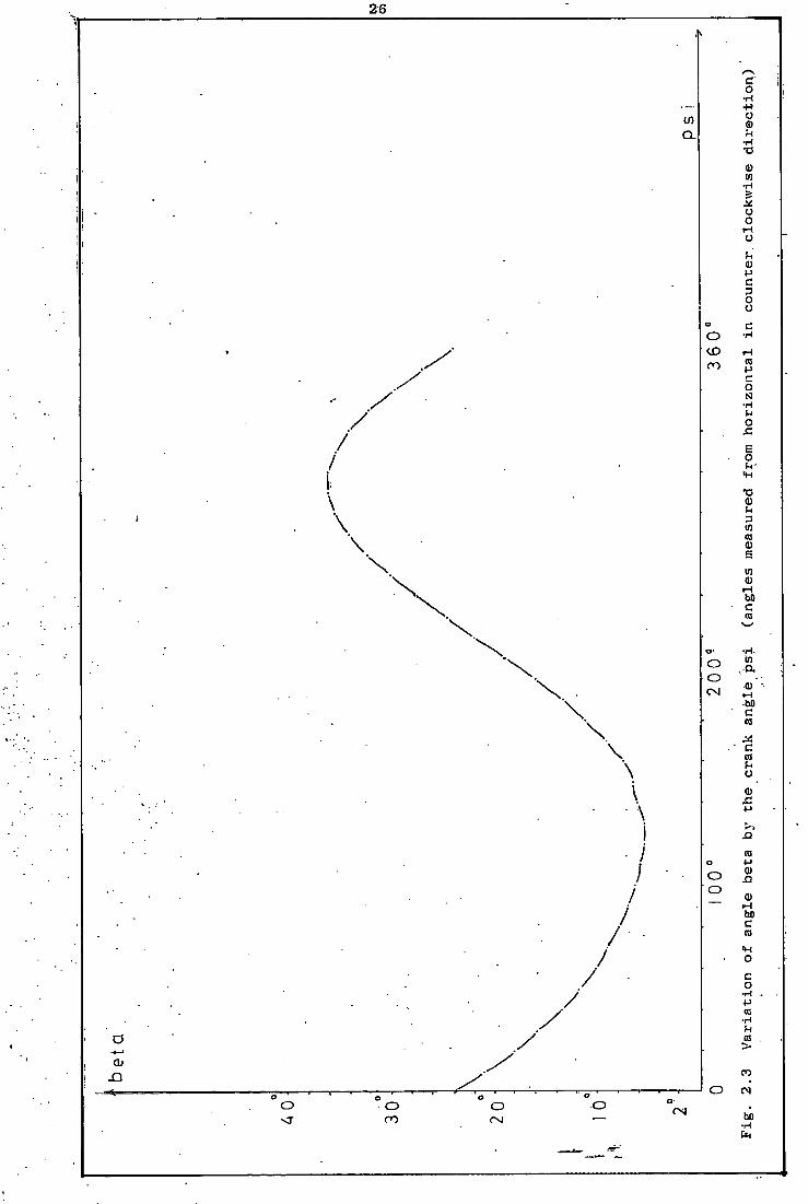
F i g . 2.3 V a r i a t i o n of angle beta w i t h the crank
angle 26
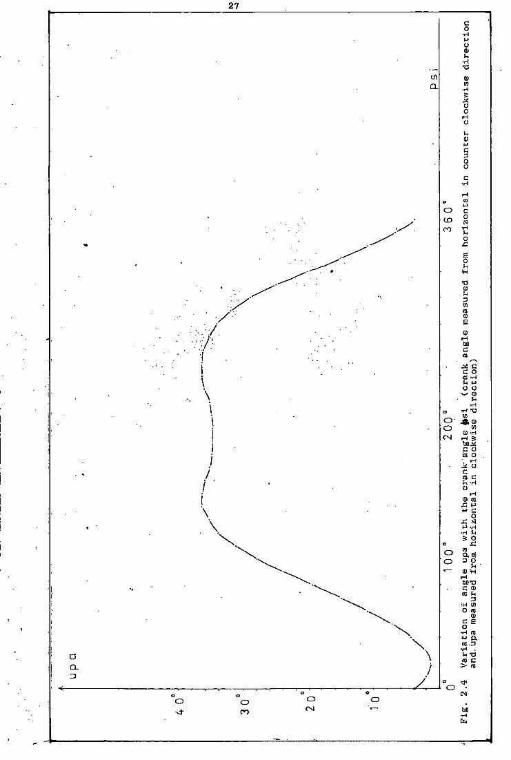
F i g . 2.4 V a r i a t i o n of angle upa w i t h the crank
angle 27
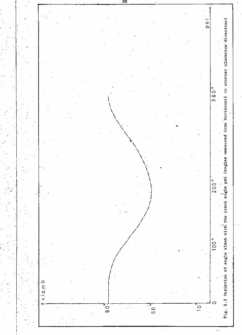
F i g . 2.5 V a r i a t i o n of angle xlamb w i t h the crank
angle 28
F i g . 2.6 V a r i a t i o n of transmission angles c a l and
yum w i t h the crank angle 29
F i g . 2.7 A n a l y t i c a l v e l o c i t y and a c c e l e r a t i o n
a n a l y s i s 35
F i g . 2.8 V a r i a t i o n of angular a c c e l e r a t i o n of
l i n k 3 w i t h the crank angle 37
F i g . 2.9 V a r i a t i o n of angular a c c e l e r a t i o n o f l i n k
4 w i t h the crank angle 38
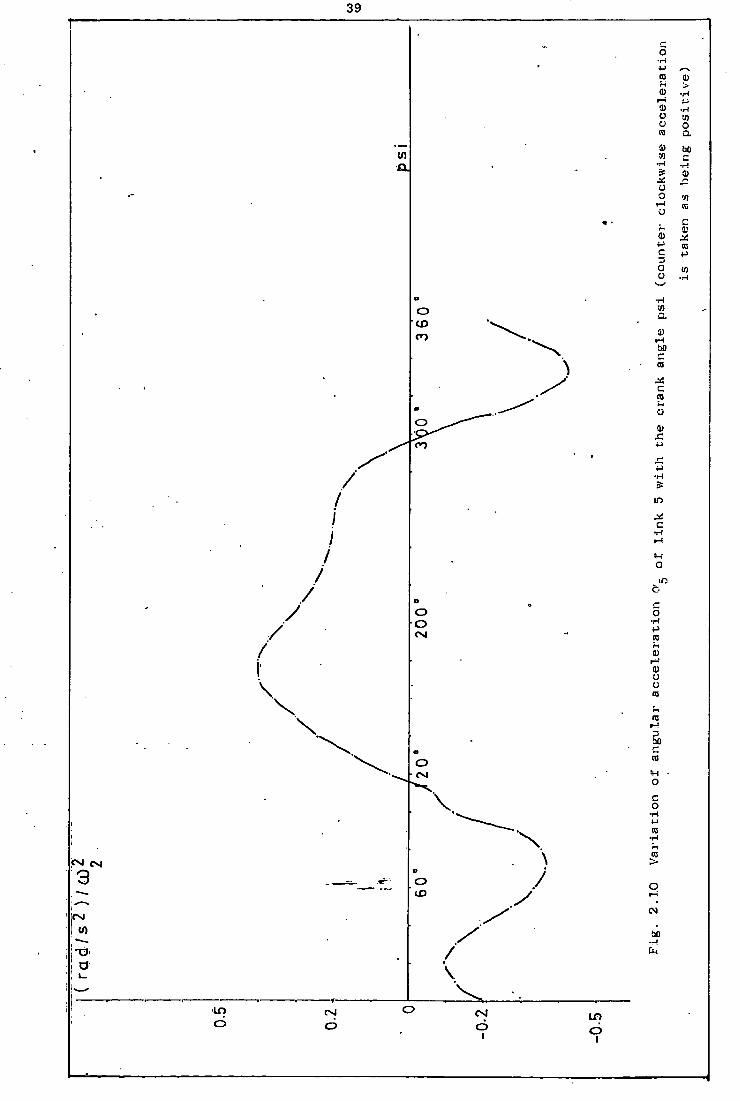
F i g . 2.10 V a r i a t i o n of angular a c c e l e r a t i o n o f l i n k
5 w i t h the crank angle 39
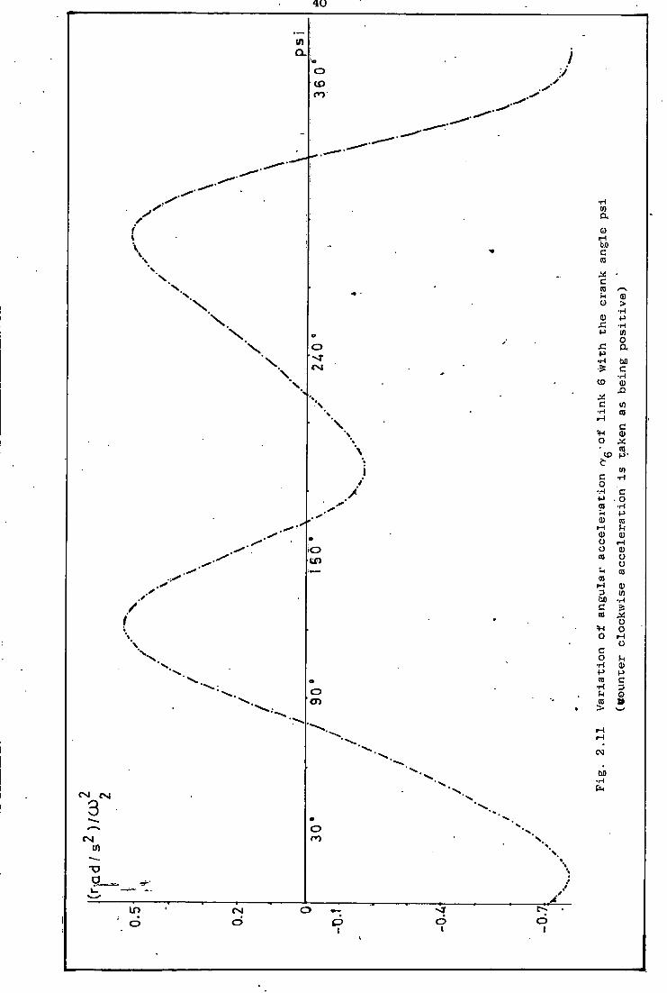
F i g . 2.11 V a r i a t i o n of angular a c c e l e r a t i o n o f l i n k
6 w i t h t h e crank angle 40
F i g . 2.12 Angular v e l o c i t y curves 41
F i g . 2.13 V a r i a t i o n o f angular v e l o c i t y r a t i o w i t h
the crank angle 42
F i g . 2.14 (a-b) 44
F i g . 2.15 Dead-centre p o s i t i o n s f o r l i n k s 4 and 6 45
F i g . 2.16 49
F i g . 2.17 V a r i a t i o n o f k i n e t i c energies o f s h a f t s
0„, 0' and l i n k s 3 and 4 w i t h the crank
angle 56
F i g . 2.18 V a r i a t i o n of the k i n e t i c energy w i t h the
crank angle 57
X
P l a t e 4.1 88
Plate 4.2 88
P l a t e 4.3 E l e c t r i c motor and speed v a r i a t o r u n i t 89
F i g . 4.3 S t a t i c b e n d i n g - s t r a i n measurement 96
F i g . 4.4 S t a t i c b e n d i n g - s t r a i n t e s t f o r l i n k 5 97
F i g . 4.5 S t a t i c b e n d i n g - s t r a i n t e s t f o r l i n k 3 98
F i g . 4.6 100
F i g . 4.7 101
F i g . 4.8 Tensile t e s t f o r l i n k s 3 and 5 102
Table 4.1 Speed f l u c t u a t i o n 105
F i g . 4.9 T h e o r e t i c a l and experimental v a r i a t i o n
of a x i a l s t r e s s range i n l i n k 5 w i t h the
crank speed 106
F i g . 4.10 Experimental v a r i a t i o n o f bending s t r e s s
range i n l i n k 3 w i t h the crank speed 107
F i g . 4.11 Experimental v a r i a t i o n of bending s t r e s s
range i n l i n k 5 w i t h the crank speed 108
F i g . 4.12 T h e o r e t i c a l and experimental v a r i a t i o n
of a x i a l s t r e s s range i n l i n k 3 w i t h the
.crank speed 109
F i g . 4.13 V a r i a t i o n o f peak t o peak stresses i n
l i n k s 3 and 5 w i t h the square o f the
crank speed 110
F i g . 4.14 Experimental s t r a i n p a t t e r n s I l l
F i g . 4.15 Experimental and t h e o r e t i c a l v a r i a t i o n
of a x i a l s t r e s s i n l i n k 3 w i t h the crank
angle 114
F i g . 4.16 T h e o r e t i c a l and e x p e r i m e n t a l . v a r i a t i o n o f
a x i a l s t r e s s i n l i n k 5 w i t h the crank angle 115
i x
F i g . 3.1 62
F i g . 3.2 Free body diagrams 63
F i g . 3.3 V a r i a t i o n of torque t r a n s m i t t e d by l i n k 4
w i t h the crank angle 67
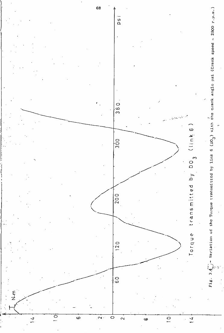
F i g . 3.4 V a r i a t i o n of torque t r a n s m i t t e d by l i n k 6
w i t h the crank angle 68
F i g . 3.5 V a r i a t i o n of Power t r a n s m i t t e d by l i n k s 4
and 6 w i t h the crank angle 69
F i g . 3.6 Graphical f o r c e a n a l y s i s by instantaneous
centres method 71
F i g . 3.7a 74
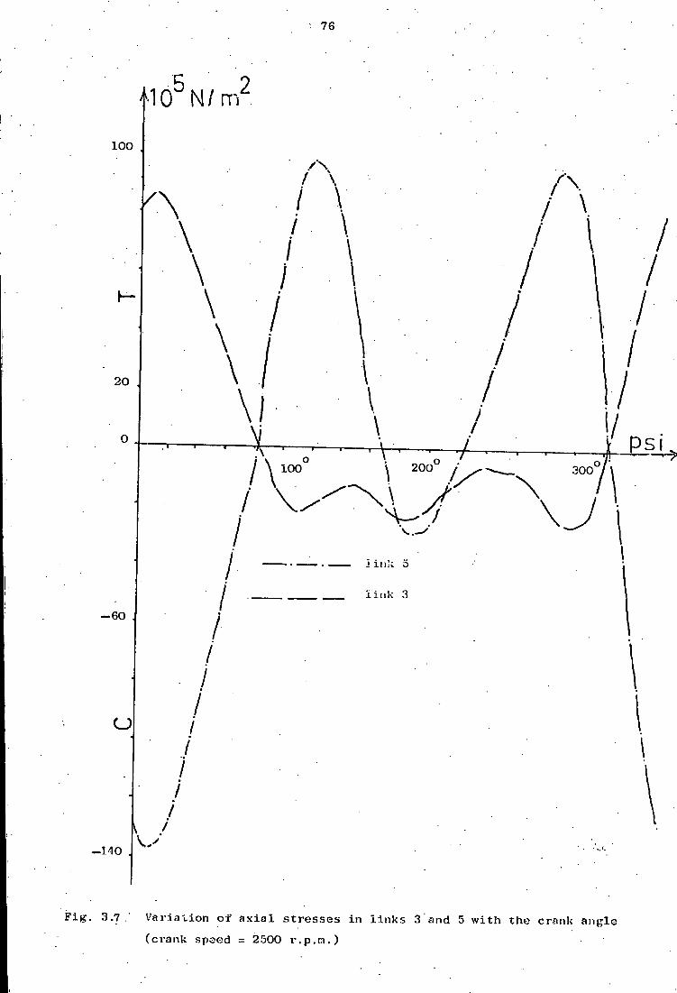
F i g . 3.7b V a r i a t i o n o f a x i a l stresses i n l i n k s 3 and
5 w i t h the crank angle 76
F i g . 3.8 T h e o r e t i c a l v a r i a t i o n of a x i a l s t r e s s
range w i t h the square o f the crank speed 77
F i g . 3.9 Connecting rod - l i n k 3 79
F i g . 3.10 Link 5 80
F i g . 3.11 V a r i a t i o n of the e x t e r n a l torque T g
required t o d r i v e the mechanism w i t h the
crank angle 81
F i g . 3.12 V a r i a t i o n o f a x i a l f o r c e - l i n k 5 w i t h
the crank angle 82
F i g . 3.13 V a r i a t i o n o f a x i a l f o r c e - l i n k 3 w i t h
the crank angle 83
F i g . 3.14 V a r i a t i o n of t h e o r e t i c a l maximum a x i a l
t e n s i l e and compressive stresses i n
l i n k s 3 and 5 w i t h the crank speed 84
F i g . 4.1 Experimental set-up Block diagram 86
F i g . 4.2 87

x i
Table 4.2 Dynamic s t r a i n measurement r e s u l t s 116
Table 4.3 S t a t i c b e n d i n g - s t r a i n measurement r e s u l t s 128
F i g . 5.1 146
F i g . 5.2 147
F i g . 5.3 , 150
Table 5.1 152
Table 5.2a and
5.2b 156
Table 5.3 . 159
Table 5.4 161
Table 5.5 162
Table 5.6 163
Table 5.7 , 164
F i g . 5.4 165
F i g . 5.5 '.. 166
F i g . 5.6 167
Fi g . 5.7 167
Appendix A3 186

x i i
Nomenclature
• = p s i
0 = Beta
Y = gama
x\ = xlamb
upa
<- AAT
AAR
*B = ABT
AB = ABR
A B f t = ABAT
*L = ABAR »l = ADR V = ADT *^ = ADCR DC A* = ADCT DC
= ADCT
On -2 0/ = 3 ANGC3
"4 = ANGC4
a -5 ANGC5
a = ANGC6 6
crank angle i n degrees - i n a d i r e c t i o n counterclockwise from
the h o r i z o n t a l
angle i n degrees between l i n k 3 and the h o r i z o n t a l , i n a
counterclockwise d i r e c t i o n from the h o r i z o n t a l
angle i n degrees between the side O C of the r i g i d t r i a n g u l a r
l i n k 4 and the h o r i z o n t a l i n a d i r e c t i o n counterclockwise
from the h o r i z o n t a l
angle i n degrees between l i n k 5 and the h o r i z o n t a l i n a
d i r e c t i o n counterclockwise from the h o r i z o n t a l
angle i n degrees between l i n k 6 and the h o r i z o n t a l i n a
d i r e c t i o n clockwise from the h o r i z o n t a l / 2
Tangential a c c e l e r a t i o n component o f A-m/s 2
Radial a c c e l e r a t i o n component of A-m/s 2
Tangential a c c e l e r a t i o n component o f B-m/s 2
Radial a c c e l e r a t i o n component of B-m/s , 2
Tangential a c c e l e r a t i o n component o f B w i t h respect t o A-m/s 2
Radial a c c e l e r a t i o n component of B w i t h respect t o A-m/s , 2
Radial a c c e l e r a t i o n component of D-m/s 2
Tangential a c c e l e r a t i o n component o f D-m/s 2
Radial a c c e l e r a t i o n component of D w i t h respect t o C-m/s 2
Tangential a c c e l e r a t i o n component of D w i t h respect t o C-m/s / 2
Angular a c c e l e r a t i o n of l i n k 2 - rad/s 2
Angular a c c e l e r a t i o n o f l i n k 3 - rad/s , 2
Angular a c c e l e r a t i o n o f l i n k 4 - rad/s 2
Angular a c c e l e r a t i o n of l i n k 5 - rad/s 2 Angular a c c e l e r a t i o n o f l i n k 6 - rad/s

x i i i
VA ' v e l o c i t y o f A-m/s
VB = VB v e l o c i t y o f B-m/s
V : = VBA v e l o c i t y of B w i t h respect t o A-m/s
VD = VD v e l o c i t y of D-m/s
VDC : = VDC v e l o c i t y o f D w i t h respect t o C-m/s
^ = OMEGA2 angular v e l o c i t y o f l i n k 2-rad/s
(JU = 3 OMEGA3 angular v e l o c i t y of l i n k 3-rad/s
00 = 4 OMEGA4 angular v e l o c i t y o f r i g i d t r i a n g u l a r l i n k 4-
U) = 5 OMEGA5 angular v e l o c i t y o f l i n k 5-rad/s
U5 = 6 OMEGA6 angular v e l o c i t y of l i n k 6-rad/s
I n
Mass moment of i n e r t i a o f the corresponding
t h e i r mass centres - kg - m
where- n = 2,3,4,5,6 2 I Mass moment of i n e r t i a of the corresponding s h a f t s - kg - m on
where n = 1,2,3 2 2
EN1 K i n e t i c energy due t o r o t a t i o n - l i n k 4 - kgm /s 2 2
EN2 K i n e t i c energy due t o r o t a t i o n - shaf t 0 - kgm /s 2 2
EN3 K i n e t i c energy due t o r o t a t i o n - sh a f t 0 - kgm /s 2 2
EN4 K i n e t i c energy due t o r o t a t i o n - l i n k 3 - kgm /s 2 2
EN5 K i n e t i c energy due t o r o t a t i o n - l i n k 5 - kgm /s . 2 2
EN6 K i n e t i c energy due t o r o t a t i o n - l i n k 6 - kgm /s
RT1 (Angular v e l o c i t y o f l i n k 3)/(angular v e l o c i t y of crank arm)
RT2 (Angular v e l o c i t y o f l i n k 4 )/(angular v e l o c i t y of crank arm)
RT3 (Angular v e l o c i t y o f l i n k 5)/(angular v e l o c i t y of crank arm)
RT4 (Angular v e l o c i t y o f l i n k 6)/(angular v e l o c i t y of crank arm)
CAL Angle of transmission i n degrees - angle ABO
YUM Angle of transmission i n degrees - angle CDO

1
I n t r o d u c t i o n
1 Stages encountered d u r i n g the development of the P r o j e c t
The primary o b j e c t i v e was t o determine both t h e o r e t i c a l l y and exper
i m e n t a l l y the a x i a l forces and t h e corresponding stresses i n two o f the
link a g e members o f the mechanism. For t h i s purpose p a i r s o f s t r a i n gauges
were placed on opposing faces o f the rods i n a c o n f i g u r a t i o n capable of
measuring a x i a l s t r a i n s as w e l l as bending s t r a i n s i n a d i r e c t i o n normal
t o the plane o f the l i n k s . Bending s t r a i n s i n the plane o f the linkage
could not be measured because o f space l i m i t a t i o n s and the complex shape
of the connecting rods which p r o h i b i t e d a l t e r n a t i v e p l a c i n g of the gauges.
Two d i f f e r e n t J bridge 120 0 strain-gauge c i r c u i t s were a v a i l a b l e t o measure
a x i a l and bending s t r a i n s independently. The bending strains.were expected
t o be zero. However i n the course of the measurements i t became apparent
t h a t s u b s t a n t i a l bending stesses were present i n these members. To confirm
the dynamic s t r a i n measurement r e s u l t s and t o determine the nature and cause
of the bending s t r a i n s a set o f s t a t i c t e s t s was c a r r i e d out on the mechanism.
The steps taken t o achieve these o b j e c t i v e s were:
1 - A d e t a i l e d examination and d e s c r i p t i o n of the machine
2 - A complete t h e o r e t i c a l kinematic, f o r c e and s t r e s s a n a l y s i s
3 - Preparation of the experimental set-up
4 - Determination of basic m a t e r i a l p r o p e r t i e s f o r the two connecting rods
5 - Measurement of dynamic s t r a i n s
6 - S t a t i c t e s t s on the mechanism aiming t o f i n d out the nature and
cause o f bending s t r a i n s i n a d i r e c t i o n normal t o the plane of
the mechanism
7 ~ Comparison and discussion o f experimental and c a l c u l a t e d r e s u l t s .
2
2 H i s t o r i c a l background t o the I n v e s t i g a t i o n
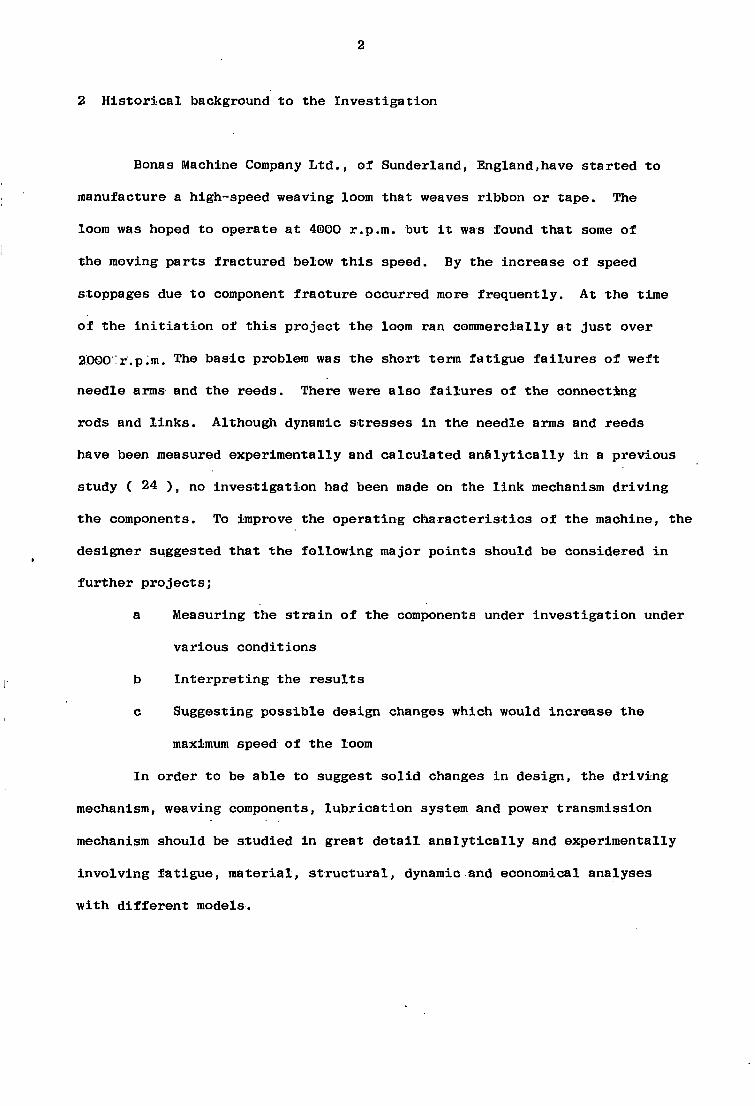
Bonas Machine Company L t d . , o f Sunderland, England,have s t a r t e d t o
manufacture a high-speed weaving loom t h a t weaves ribbon or tape. The
loom was hoped t o operate a t 4000 r.p.ra. but i t was found t h a t some o f
the moving p a r t s f r a c t u r e d below t h i s speed. By the increase of speed
stoppages due t o component f r a c t u r e occurred more f r e q u e n t l y . At the time
o f the i n i t i a t i o n of t h i s p r o j e c t the loom ran commercially at j u s t over
2000:r.p;m. The basic problem was the short term f a t i g u e f a i l u r e s o f weft
needle arms and the reeds. There were a l s o f a i l u r e s of t h e connectjsng
rods and l i n k s . Although dynamic stresses i n the needle arms and reeds
have been measured experim e n t a l l y and c a l c u l a t e d a n a l y t i c a l l y i n a previous
study ( 24 ) , no i n v e s t i g a t i o n had been made on the l i n k mechanism d r i v i n g
the components. To improve the op e r a t i n g c h a r a c t e r i s t i c s o f the machine, the
designer suggested t h a t the f o l l o w i n g major p o i n t s should be considered i n
f u r t h e r p r o j e c t s ;
a Measuring the s t r a i n o f the components under i n v e s t i g a t i o n under
various c o n d i t i o n s
b I n t e r p r e t i n g the r e s u l t s
c Suggesting p o s s i b l e design changes which would increase t h e
maximum speed of the loom
I n order t o be able t o suggest s o l i d changes i n design, the d r i v i n g
mechanism, weaving components, l u b r i c a t i o n system and power transmission
mechanism should be st u d i e d i n great d e t a i l a n a l y t i c a l l y and experimentally
i n v o l v i n g f a t i g u e , m a t e r i a l , s t r u c t u r a l , dynamic and economical analyses
w i t h d i f f e r e n t models.

3
3 Plane Mechanisms i n G e n e r a l , c u r r e n t r e s e a r c h and s h o r t b i b l i o g r a p h i c a l
review
I f a l l p o i n t s of the curves of motion of a l l the l i n k s of a mechanism
l i e i n one and on the same plane, the mechanism i s c a l l e d a plane mechanism.
A mechanicsm can simply be d e f i n e d as a combination of machine elements
arranged to a c h i e v e a c e r t a i n motion. S i n c e i t d e a l s w i t h the composition
of members of a machine i n t o an assemblage to perform a t a s k , to produce
a new and unusual r e s u l t , mechanisms a r e one of the most f a s c i n a t i n g t o p i c s
i n the f i e l d of mechanical e n g i n e e r i n g . Machine design i s a c r e a t i v e a r t
i n v o l v i n g the p o s s e s s i o n of c a r e f u l a n a l y t i c a l a b i l i t y , good judgement and
a broad e x p e r i e n c e . The b a s i c f a c t o r s which must be taken i n t o c o n s i d e r a t i o n
i n g e n e r a l machine design a r e : u t i l i t y , s a f e t y , c o s t , s t r e n g t h , r i g i d i t y ,
d e f l e c t i o n , f r i c t i o n , l u b r i c a t i o n , wear, heat, n o i s e , f l e x i b i l i t y , c o n t r o l
and appearance. A tremendous amount of work has been p u b l i s h e d on v a r i o u s
a s p e c t s of mechanisms e s p e c i a l l y i n the l a s t two decades. The i n t r o d u c t i o n
of computers i n t o design work has a c c e l e r a t e d the r e s e a r c h a g r e a t d e a l .
Numerous new methods have been developed. Today the techniques f o r s t u d y i n g
the dynamics of mechanisms can be c l a s s i f i e d a s k i n e t o - s t a t i c or time
response approaches ( 4 ) . Current r e s e a r c h t o p i c s i n the f i e l d a r e
concentrated on:
( a ) Optimum mechanism d e s i g n combining k i n e m a t i c and dynamic f o r c e
c o n s i d e r a t i o n s .
( b ) S y n t h e s i s of l i n k a g e f u n c t i o n generators by means of mathematical
methods, models and computers.
( c ) Shaking and b e a r i n g f o r c e o p t i m i z a t i o n .
(d) Experimental and t h e o r e t i c a l study of connection f o r c e s and
frequency response c h a r a c t e r i s t i c s .
4
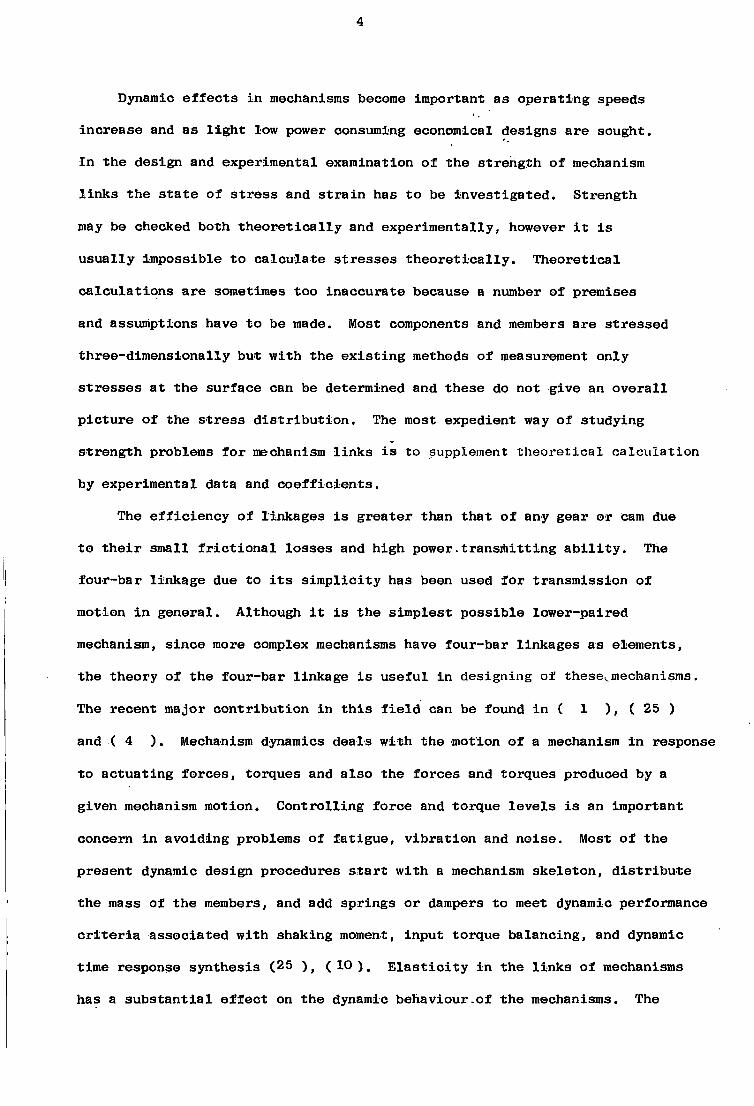
Dynamic e f f e c t s i n mechanisms become important as o p e r a t i n g speeds
i n c r e a s e and as l i g h t low power consuming economical designs a r e sought.
I n the design and experimental examination of the s t r e n g t h of mechanism
l i n k s the s t a t e of s t r e s s and s t r a i n has t o be i n v e s t i g a t e d . S t r e n g t h
may be checked both t h e o r e t i c a l l y and e x p e r i m e n t a l l y , however i t i s
u s u a l l y i m p o s s i b l e to c a l c u l a t e s t r e s s e s t h e o r e t i c a l l y . T h e o r e t i c a l
c a l c u l a t i o n s a r e sometimes too i n a c c u r a t e because a number of premises
and assumptions have t o be made. Most components and members a r e s t r e s s e d
t h r e e - d i m e n s i o n a l l y but w i t h the e x i s t i n g methods of measurement only
s t r e s s e s a t t h e s u r f a c e can be determined and t h e s e do not give an o v e r a l l
p i c t u r e of the s t r e s s d i s t r i b u t i o n . The most expedient way of s t u d y i n g
s t r e n g t h problems f o r mechanism l i n k s i s to supplement t h e o r e t i c a l c a l c u l a t i o n
by experimental data and c o e f f i c i e n t s .
The e f f i c i e n c y of l i n k a g e s i s g r e a t e r than t h a t of any gear or cam due
t o t h e i r s m a l l f r i c t i o n a l l o s s e s and high power.transmitting a b i l i t y . The
four-bar l i n k a g e due to i t s s i m p l i c i t y has been used f o r t r a n s m i s s i o n of
motion i n g e n e r a l . Although i t i s the s i m p l e s t p o s s i b l e l o w e r - p a i r e d
mechanism, s i n c e more complex mechanisms have four-bar l i n k a g e s as elements,
the theory of the four-bar l i n k a g e i s u s e f u l i n d e s i g n i n g of these^mechanisms.
The r e c e n t major c o n t r i b u t i o n i n t h i s f i e l d can be found i n ( 1 ) , ( 25 )
and ( 4 ) . Mechanism dynamics d e a l s w i t h the motion of a mechanism i n response
to a c t u a t i n g f o r c e s , torques and a l s o the f o r c e s and torques produced by a
given mechanism motion. C o n t r o l l i n g f o r c e and torque l e v e l s i s an important
concern i n a v o i d i n g problems of f a t i g u e , v i b r a t i o n and n o i s e . Most of the
present dynamic design procedures s t a r t w i t h a mechanism s k e l e t o n , d i s t r i b u t e
the mass of the members, and add s p r i n g s or dampers to meet dynamic performance
c r i t e r i a a s s o c i a t e d w i t h shaking moment, input torque b a l a n c i n g , and dynamic
time response s y n t h e s i s (25 ) f ( 10 ) . E l a s t i c i t y i n the l i n k s of mechanisms
has a s u b s t a n t i a l e f f e c t on the dynamic behaviour.of the mechanisms. The
5
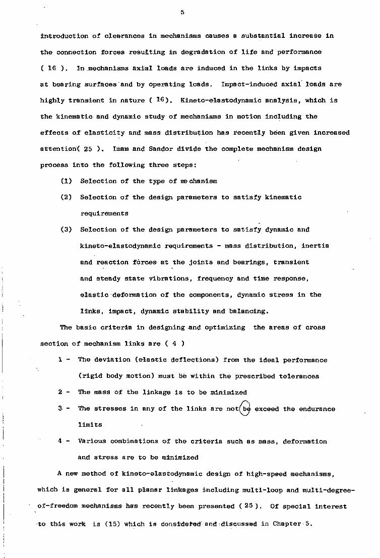
i n t r o d u c t i o n of c l e a r a n c e s i n mechanisms causes a s u b s t a n t i a l i n c r e a s e i n
the connection f o r c e s r e s u l t i n g i n degradation of l i f e and performance
( 16 ) . I n mechanisms a x i a l loads a r e induced i n the l i n k s by impacts
a t b e a r i n g s u r f a c e s and by o p e r a t i n g loads. Impact-induced a x i a l loads a r e
h i g h l y t r a n s i e n t i n nature ( 1 6 ) . Kineto-elastodynamic a n a l y s i s , which i s
the k i n e m a t i c and dynamic study of mechanisms i n motion i n c l u d i n g the
e f f e c t s o f e l a s t i c i t y and mass d i s t r i b u t i o n has r e c e n t l y been given i n c r e a s e d
a t t e n t i o n ^ 25 ) . Imam and Sandor d i v i d e the complete mechanism design
process i n t o the f o l l o w i n g t h r e e s t e p s :
( 1 ) S e l e c t i o n of the type of mechanism
(2) S e l e c t i o n of the design parameters to s a t i s f y k i n e m a t i c
requirements
( 3 ) S e l e c t i o n of the design parameters to s a t i s f y dynamic and
k i n e t o - e l a s t o d y n a m i c requirements - mass d i s t r i b u t i o n , i n e r t i a
and r e a c t i o n f o r c e s a t the j o i n t s and b e a r i n g s , t r a n s i e n t
and steady s t a t e v i b r a t i o n s , frequency and time response,
e l a s t i c deformation of the components, dynamic s t r e s s i n the
l i n k s , impact, dynamic s t a b i l i t y and b a l a n c i n g .
The b a s i c c r i t e r i a i n d e s i g n i n g and o p t i m i z i n g the a r e a s of c r o s s
s e c t i o n of mechanism l i n k s a r e ( 4 )
1 - The d e v i a t i o n ( e l a s t i c d e f l e c t i o n s ) from the i d e a l performance
( r i g i d body motion) must be w i t h i n the p r e s c r i b e d t o l e r a n c e s
2 - The mass of the l i n k a g e i s to be minimized
4 - Various combinations of the c r i t e r i a such as mass, deformation
and s t r e s s a r e to be minimized
A new method of kineto-elastodynamic design of high-speed mechanisms,
which i s general f o r a l l p l a n a r l i n k a g e s i n c l u d i n g m u l t i - l o o p and multi-degree-
of-freedom mechanisms has r e c e n t l y been presented ( 25 ) . Of s p e c i a l i n t e r e s t
to t h i s work i s (15) which i s considered and d i s c u s s e d i n Chapter 5.
3 The s t r e s s e s i n any of the l i n k s a r e notfbe exceed the endurance 0 ) l i m i t s

6
Chapter 1.
D e s c r i p t i o n of the Machine.
The machine i s a s m a l l v a r i a b l e high-speed ., weaving loom designed
to manufacture ribbon or tape. The main body c o n s i s t s of a r i g i d s t e e l
case e n c l o s i n g the sump and l u b r i c a t i n g mechanism above which i s mounted
_an-H=shaped mechanism u n i t box. The whole complex i s mounted on a
17 - shaped J box s e c t i o n s t e e l platform. The main c o n t r o l box i s mounted
~~on~~the^right s i d e of the body w h i l e the opposing f a c e i s r e s e r v e d f o r the
power t r a n s m i s s i o n . An i n s p e c t i o n cover i s f i t t e d t o the f r o n t of the main
body. The important weaving components a r e mounted e x t e r n a l l y to the r e a r
and top of the mechanism u n i t box. The main body and b a s i c f e a t u r e s a r e
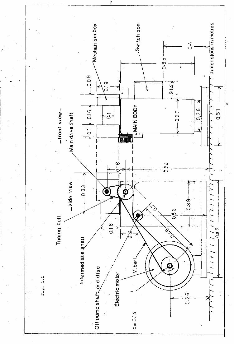
shown i n F i g . (1.1) and P l a t e (1.1)
1.1 Power T r a n s m i s s i o n System
O r i g i n a l l y an " E l e k t r i m 1410 r.p.m., 1.1 kw. 1.5 HP, 415 V. 2.5 amp"
constant speed e l e c t r i c motor was f i t t e d to the r e a r of the main body. The
replacement was a 3 phase, 2 HP v a r i a b l e speed (480-4320 output r.p.m.)
e l e c t r i c motor. The motor was mounted on the r e a r end of the jj -shaped
platform, complete w i t h an a d j u s t a b l e c a r r i a g e which enabled b e l t adjustment
to be c a r r i e d out. AC c u r r e n t i s taken d i r e c t l y from the f l o o r by an i n s u l a t e d
c a b l e fed i n t o the s w i t c h box. A "Fenner B 1800 B69" V - b e l t was used to
tr a n s m i t the power t o the in t e r m e d i a t e s h a f t . F i t t e d to the i n t e r m e d i a t e
s h a f t was a 40 tooth p u l l e y d r i v i n g v i a a timin g b e l t the 20 tooth p u l l e y
f i t t e d t o the main d r i v e s h a f t . The ti m i n g b e l t used was "Fenner 240 L 100"
The V - b e l t a l s o drove the oil-pump s h a f t end d i s c . ( F i g . 1.1). A handwheel/
fl y w h e e l was a t t a c h e d to the main d r i v e s h a f t . The in t e r m e d i a t e V - b e l t
p u l l e y was manufactured to s u i t the a v a i l a b l e b e l t . A l l p u l l e y s were f i t t e d
to t h e i r r e s p e c t i v e s h a f t s u s i n g " t a p e r - l o c k " d r i v e d e v i c e . The two i n t e r
mediate p u l l e y s were f i r s t screwed together before f i t t i n g to the s h a f t .
1
CO CD
CD
ifl CO 10 CO CD to
CD CD
CD
o 7 s
to CD CD O 0) o o
CO CD
co
CD
CD •—
CD CD
c9 7? 1/ CD
CO O)
«0
CO
V / CD
CO / CD
CD
CO
/ 1 CD
CD CO CN
CD O CO l±J
II

8
At speeds i n e x c e s s of 2500 r.p.m. (main d r i v e s h a f t speed) s l i p was
det e c t e d between " t a p e r - l o c k " d e v i c e and the main d r i v e s h a f t . Due t o
v e r t i c a l e c c e n t r i c i t y i n the axes o f t h e motor p u l l e y , i n t e r m e d i a t e
s h a f t and main d r i v e s h a f t excess wear was observed on the v - b e l t and on
the t i m i n g b e l t .
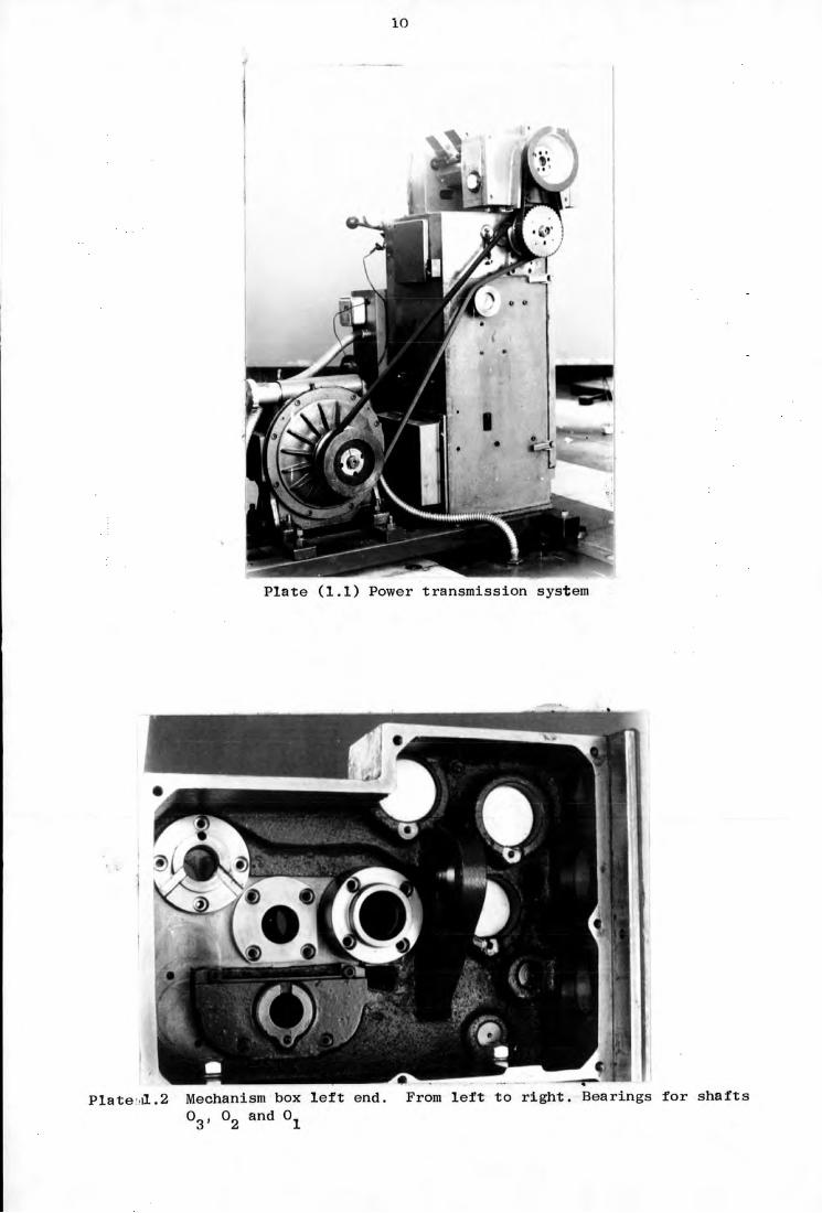
1.2 Mechanism U n i t box.
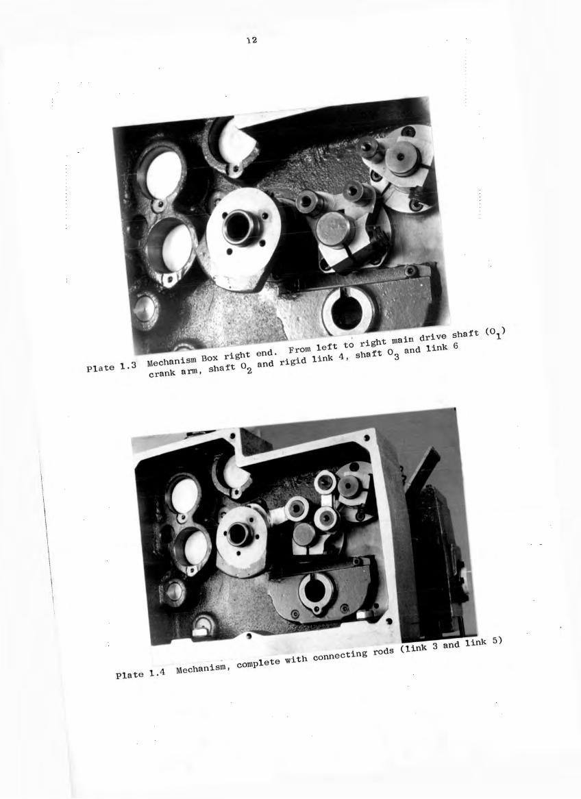
The l e f t ( d r i v e ) and r i g h t (output) end s e c t i o n s of the mechanism u n i t
box, w i t h covers removed, a r e shown i n P l a t e s (1.2) and ( 1 . 3 ) . P l a t e (1.4)
shows the r i g h t end. s e c t i o n complete w i t h connecting rods. I n f i g u r e s (1.2)
and (1.3) the mechanism i s shown as a c t u a l s h a f t s and l i n k s and as p i n
j o i n t e d rods r e s p e c t i v e l y . The main d r i v e s h a f t goes through 0 1 c a u s i n g
the crank arm O^A to r o t a t e w i t h constant angular v e l o c i t y . The r o t a r y
motion o f the crank arm i s t r a n s m i t t e d to the r i g i d t r i a n g u l a r l i n k 4 v i a
the coupler ( l i n k 3 ) . The crank arm;, coupler and r i g i d l i n k 4 re p r e s e n t
an o f f s e t c r a n k - r o c k e r mechanism. The o s c i l l a t o r y motion o f l i n k 4 i s
t r a n s m i t t e d t o s h a f t 0 g v i a the connecting rod l i n k 5 and l i n k 6. The
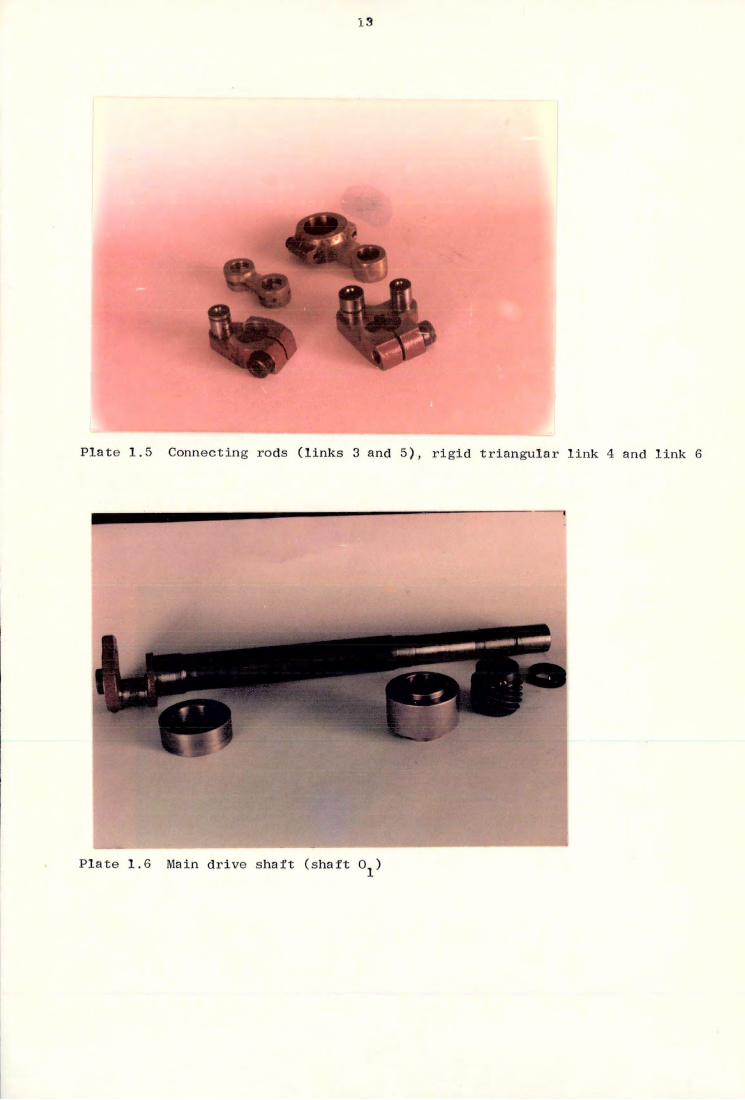
connecting rods, r i g i d l i n k 4 and l i n k 6 a r e shown i n P l a t e ( 1 . 5 ) . The
s p e c i f i c a t i o n o f the l i n k s a r e given i n the f o l l o w i n g t a b l e :
.Table 1.1
L i n k No.
M a t e r i a l Experimental L o c a t i o n o f Mass c e n t r e s
Experimental Moment of i n e r t i s about mass centre kg - m 2
Experimental BHN
3 Phosphor Bronze a l l o y
12 mm from A 5.84 x 1 0 - 5 117
4 Carbon S t e e l 7. 5 mm jfrom 0_ 30O from "2 C 2
"4.35 x 10~ 5 -
5 Phosphor Bronze a l l o y 1.45 mm from C
-6 7.5 x 10 142
6 Carbon s t e e l 1 mm from 0g .2.26 x 10" 5 -

9
CD
CO
/ CO
CO CD CM
/ c
bi:
CM
03 CO
ID
CO
\
en
c & m »- CO
10
\
P l a t e (1.1) Power t r a n s m i s s i o n system
i
P l a t e i l . 2 Mechanism box l e f t end. From l e f t to r i g h t . Bearings f o r s h a f t s 0_ and 0 0

I I
if)
O \—
"O
"c
c a
c o
"c U J C u
E E E I I <
E E
CN
I I QQ <
E E
CN CN
I I u
CN O cn fN I I CN U CN III CO
O Q O 00 O O
E E
E E o
12
I
"«V i ^ ^ ^ ^ ^ r i v e s h a f t (O.) ' , From l e « to r i ^ - ^ 6
?
•
• i
3 and rods d i n * W i t h connecting
complete 4 Mechani SID P l a t e 1
13
if •
P l a t e 1.5 Connecting rods ( l i n k s 3 and 5 ) , r i g i d t r i a n g u l a r l i n k 4 and l i n k 6
P l a t e 1.6 Main d r i v e s h a f t ( s h a f t 0.)
14
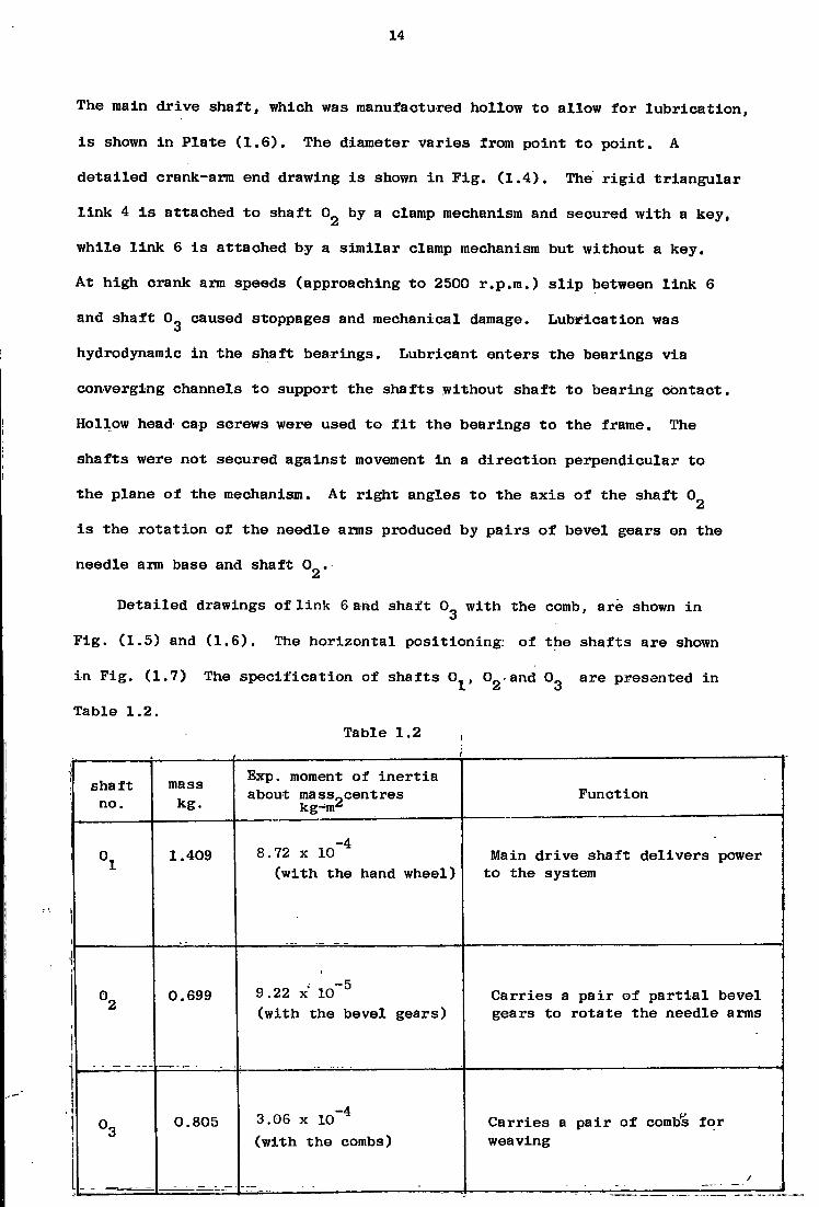
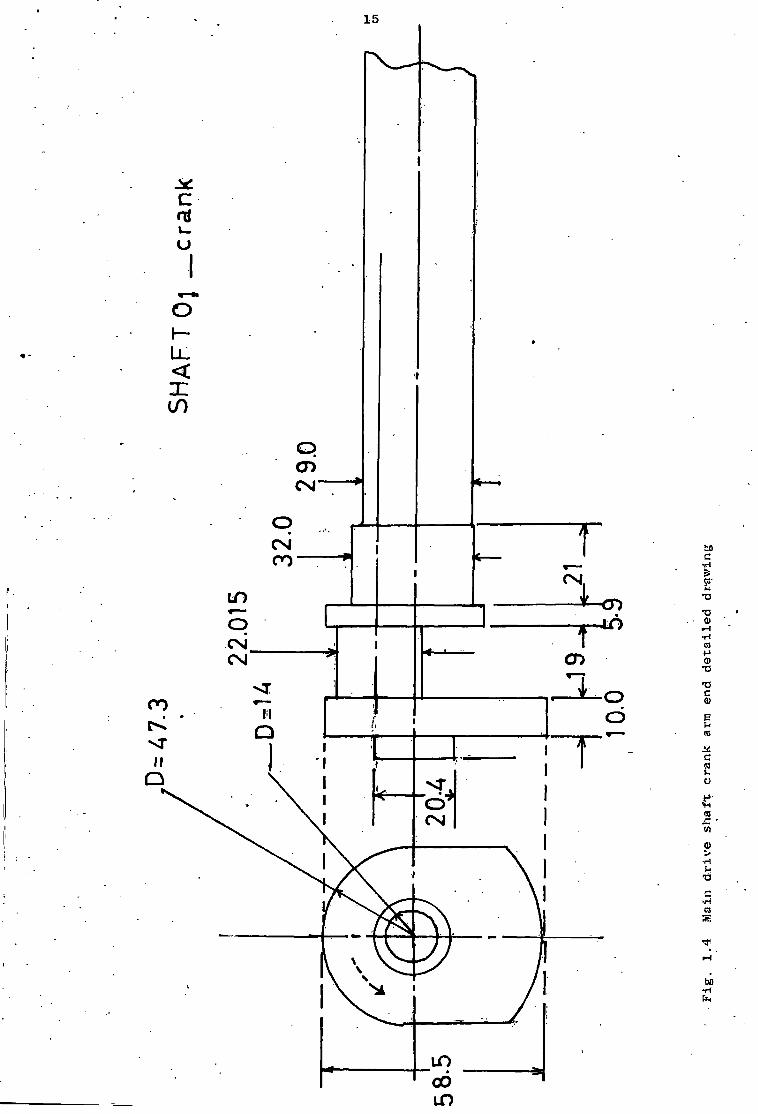
The main d r i v e s h a f t , which was manufactured hollow to allow f o r l u b r i c a t i o n ,
i s shown i n P l a t e ( 1 . 6 ) . The diameter v a r i e s from point t o p o i n t . A
d e t a i l e d crank-arm end drawing i s shown i n F i g . ( 1 . 4 ) . The r i g i d t r i a n g u l a r
l i n k 4 i s attached t o s h a f t 0 by a clamp mechanism and secured w i t h a key,
w h i l e l i n k 6 i s a t t a c h e d by a s i m i l a r clamp mechanism but without a key.
At high crank arm speeds (approaching t o 2500 r.p.m.) s l i p between l i n k 6
and s h a f t 0^ caused stoppages and mechanical damage. L u b r i c a t i o n was
hydrodynamic i n the s h a f t b e a r i n g s . L u b r i c a n t e n t e r s the bearings v i a
converging channels t o support the s h a f t s without s h a f t t o b e a r i n g c o n t a c t .
Hollow head cap screws were used to f i t the b e a r i n g s to the frame. The
s h a f t s were not secured a g a i n s t movement i n a d i r e c t i o n p e r p e n d i c u l a r to
t h e plane of the mechanism. At r i g h t angles to the a x i s o f the s h a f t 0
i s the r o t a t i o n of the needle arms produced by p a i r s o f b e v e l gears on the
needle arm base and s h a f t 0 .
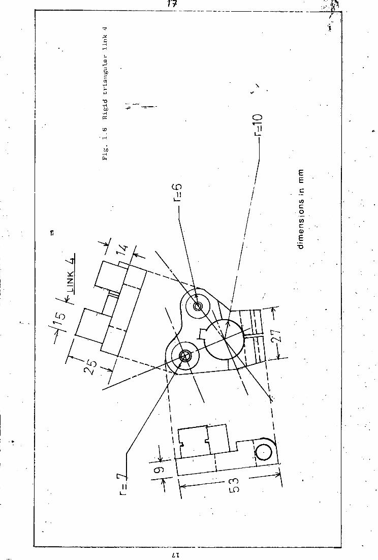
D e t a i l e d drawings of l i n k 6 and s h a f t 0 g w i t h the comb, a r e shown i n
F i g . (1.5) and ( 1 . 6 ) . The h o r i z o n t a l p o s i t i o n i n g : of the s h a f t s a r e shown
i n F i g . (1.7) The s p e c i f i c a t i o n of s h a f t s 0 , 0 - and 0 a r e presented i n
Table 1.2. Table 1.2 ,
sha f t no.
mass kg.
Exp. moment of i n e r t i a about m a s s 0 c e n t r e s
kg^nr Fu n c t i o n
°1 1.409 8.72 x l o " 4
( w i t h the hand wheel) Main d r i v e s h a f t d e l i v e r s power
to the system
°2 0.699 9.22 x 1 0 ~ 5
( w i t h the bevel g e a r s ) C a r r i e s a p a i r of p a r t i a l bevel gears to r o t a t e the needle arms
°3 0.805 3.06 x 1 0 - 4
( w i t h the combs) C a r r i e s a p a i r of combs f o r weaving
15
«r—«•
o I — L L
if)
CD CNI
CNI bo
04
•a •a (D to
CNI CD CN a)
i T3 0) CO
I
> I I
(0 CN V)
0
bo
LO CO LO

16
o
n O)
in to
a) n CO
II T 3
I
- t
o LO
ftf
-H en K
1 r n -a
17
bO
o *— II
CO I
CO
7
\ t o
r <0
\ 0
CD CO
i i LO
LI

18
CO
tr
LU 1
ID LD
I
1
CO OQ
ID
en
Q C3 EC
LL U J
o \ CO
M l
C3 \ COl
\
Vd
\
NI n ( J 17}
he Cfl
UJ UJ > cc Q
19
The experimental moment of i n e r t i a values presented i n Tables 1.1
and 1.2 are determined by a t r i f i l a r suspension. The needle arms and
shaft Og with the comb and bearings are shown in Plates 1..9 and 1.10.
The masses of l i n k s 3, 4, 5 and 6 are: 0.116 kg, 0.116 kg, 0.0283 kg and
0.0749 kg respectively. The mass centres of the l i n k s are determined by
using a knife edge. The top view of the mechanism unit box and shaft 0
are shown in plates 1.7 and 1.8 respectively.

20
• I i
Mechanism u n i t box. Bevel gears c a r r i e d by l i n k 0 P l a t e 1.7 Top view weft needle arm, s h a f t 0_ and the reed
P l a t e 1.8 Shaft 0 s h a f t bearings, a nd the bevel gears

21
V
P l a t e 1.9 Needle arms
is
P l a t e 1.10 Shaft 0 comb and bearings

22
Chapter 2
Kinematic Analysis of the Mechanism
2.1. Introduction to Kinematic Analysis of the Mechanism
Recently a variety of methods have been developed for dynamic and
kinematic analysis of mechanisms such as methods based on kinematic
constraints, motor'a'lgebra, matrix methods, quaternion and dual-number
methods, r e l a t i v e motion and incremental equations u t i l i z i n g numerical
methods, i n addition to the c l a s s i c a l methods. Other basic methods are;
Quinn's energy d i s t r i b u t i o n method, Lagrangian method, solutions employing
complex polar notation and complex numbers, kineto-elastodynamic analysis,
Raven's analysis, velocity analysis by instantaneous centres, velocity
analysis by components, velocity and acceleration image method, graphical
and a n a l y t i c a l velocity and acceleration analysis and various algebraic
methods. In the following sections a complete kinematic analysis of the
mechanism i s presented to specify the motion of the mechanism and to
determine the kinematic values. I t i s assumed that a l l the l i n k s of the
mechanism move in the same plane and the crank speed i s constant.
2.2 Geometry of the Mechanism
From F i g . (2.1); for . 0° ^360°
C L E cos( f.) (0.0.11)
AE s i n ( « ) (0.0JL1)
AF AE + 0.005
0.048 - 0,E
AO (AF) + (0„F) 2
AF tan -1

23
CM
(JJO •H p4
6 Z 0-0

24
-1 0.00128 - ( A 0 o ) 2
zek = cos 2
(-0.044) ( A 0 2 ) 2
-1 0.002248 - ( A 0 „ ) 2
c a l = cos 2
(0.001848
<x = 180° - (zek + c a l )
B = a - Tl
Y = 180° - ( 71+ zek + 75° )
_ ! 0.032 - s i n ( y ) (0.022) 9 = tan
0.042 - cos (y) (0.022)
0.032 - s i n (y ) (0.022) CO 3
van == cos
si n ( fi .)
-1 ( 0 . 0 2 9 ) 2 + ( C 0 3 ) 2 - ( 0 . 0 2 ) 2
( 0 . 0 2 9 ) 2 (co ) 3
x \ = van + fl
-1 ( 0 . 0 2 ) 2 + ( C 0 o ) 2 - ( 0 . 0 2 9 ) 2
CO = cos 3 (0 .04) ( C 0 3 )
upa = c o - teta
yum = 180° -(x^ + upa)
a l l the angles are i n degrees. Relationships between ^ , y> x X a m * u P a
depend upon the lin k lengths. Numerical variation of y, Q, x\ and upa with
^ are given i n (A 1 ) and are shown graphically i n Figures ( 2 . 2 ) , (2*3)
(2 .4 ) and ( 2 . 5 ) . Variation of the transmission angles, c a l and yum with
^ are shown in F i g . (2 .6)
2 .3 Velocity and Acceleration Analysis - Analytic method
Angular positions of l i n k s 3 ,4 ,5 and 6 are determined r e l a t i v e to the
x axis

25
in CL 0
0
0
CD
i.0
in as CD
in 0 bO
/ /
in / 0)
\ bo as
CO CD
0
cs
bo 0 bo
as O CD
\ \ as
as
CM / LO LO
bO
28
30
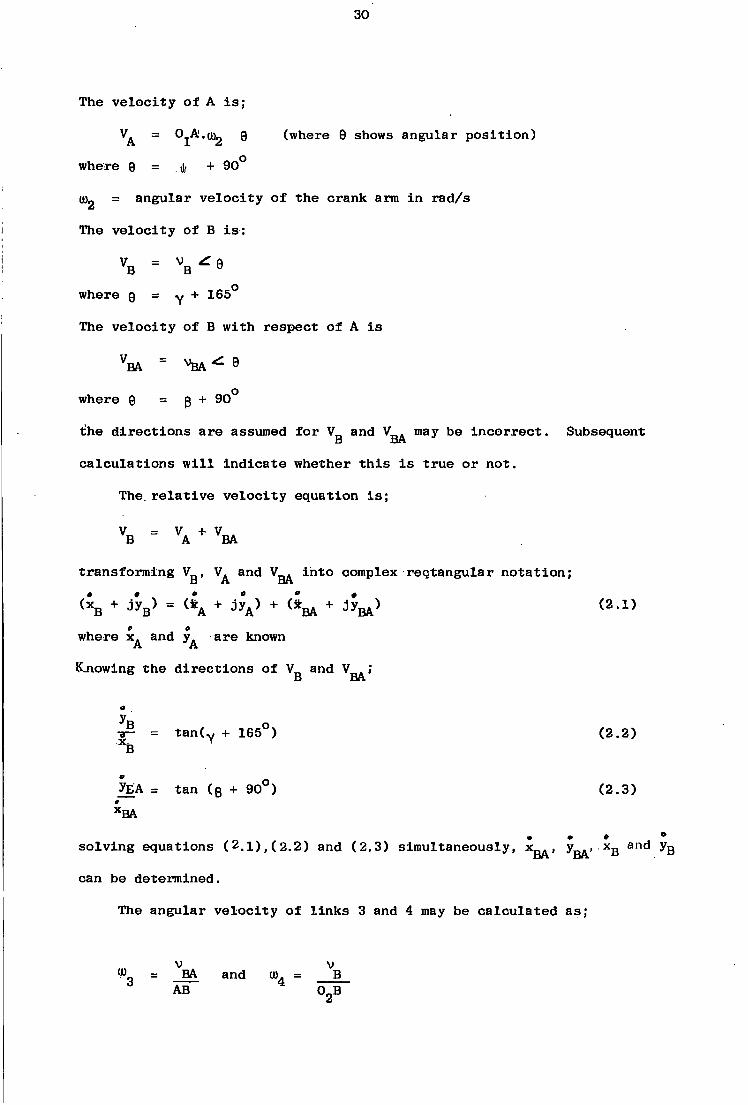
The velocity of A i s ;
VA = OjA'.tug q (where 9 shows angular position)
where 9 = j, + 90°
(Bg = angular velocity of the crank arm i n rad/s
The velocity of B i s :
where 9 = y + 165°
The veloci t y of B with respect of A i s
V- = V b a ^ 9
where 9 = g + 90°
the directions are assumed for V and V . may be incorrect. Subsequent
calculations w i l l indicate whether t h i s i s true or not.
The. r e l a t i v e velocity equation i s ;
V = V. + V A B A BA
transforming V^, and into complex rectangular notation;
+ j y B ) = <* A + j y A ) + ( * M + j y M ) (2.1) c o
where and y^ are known
K_nowing the directions of V and V ; B BA
y B 0
TF- = t a n ( Y + 165 ) (2.2) *B
y£A = tan (g + 90°) (2.3) *BA
* • »
solving equations ( 2 . 1 ) , (2.2) and (2.3) simultaneously, x ^ , y^, x Q and
can be determined.
The angular velocity of l i n k s 3 and 4 may be calculated as;
v v ® 3 = _BA and u>4 = B AB 0 oB

31
from the geometry of the mechanism;
v = v ( i n magnitude) B C
C C
where
e = y • K 9 0 °
the velocity of D i s ;
V = V ^ a D D where
6 = 90° - u p a
the velocity of D with respect of C i s ;
V v A DC DC 0
where
0 = x x + 90° the r e l a t i v e velocity equation i s ;
% " VC + V transforming into complex rectangular notation;
(*D + JV = (*C + J' yC ) + (*DC + j y D C ) ( 2 ' 4 )
knowing the directions of and V
yD = tan (90 - upa) (2.5)
XD
y JXL = tan (x\ + 90°) (2.6) x DC
solving equations (2.4),(2.5) and (2.6) simultaneously, 0 0 # V •v v v and y„ c a n be determined DC' yDC' D D
thus, the angular velocity of l i n k s 5 and 6 are;

32
U) = DC and OJ = ^ o o — DC DO o
the components of acceleration can be obtained as follows;
A A * = °1 A *2 * 0
where o
e = t + 90
A A* = 0, since = 0
V = °1 A- ">22 8
where
9 = -(180° - .* )
ABA r = A B - ^ 9
where
9 = -(180° " 3)
A B r = °2 B' » 4 2 Z - 0
where
9 = "[180° - (75° + Y)1
from the geometry of the mechanism;
r r A = A_ (i n magnitude)
A * = A * ( i n magnitude) B L
t t both A A and A„ are unknown and are to be dete'raiined BA B The r e l a t i v e acceleration equation i s ;
A * + A nr = A * + A A
r + A * + A „ Ar (2.7) B B A A BA BA
transforming the acceleration components into complex rectangular notation
and substituting into equation (2.7) produces

33
t , t <x B + dy B ) + ( x Br + j y B
r ) = ( x Ar + j y / ) + ( x ^ + J y ^ * ) + + j y / )
(2.8)
the required slopes of these components are such that;
" t = tan (v + 1 6 5°) < 2- 9>
V r X B
t V n A „ o -p- = tan (90 + p) (2.io) "flA
by equating the re a l and imaginary parts of equation (2.8) and solving t ** t " t " t simultaneously with equations (2.9) and (2.10) gives x , y , x and y_,A B Q Bn BA
The acceleration of B i s ;
A n = A * + A r
B B B
where . t " t V t A„ = x„ + j y B B J , B
acceleration of l i n k 3 i s ;
ABA = AW + ABk where • •
A t t t BA = XBA + j yBA
the angular acceleration of l i n k s 3 and 4 are;
a t a t Of = BA 01 = B
AB 0 2B
si m i l a r l y , the r e l a t i v e acceleration equation for l i n k s 4, 5 and 6 can be
written as
A * + A * = A „ r + A * + A * + A _ r
D D C C DC DC (2.11)
34
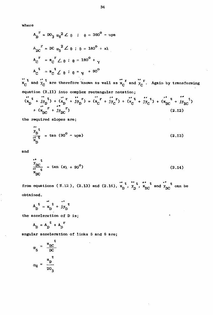
where
A Dr = D0 3 u ) 6
2 Z e ; e = 360° - upa
A D Cr = DC u, 5
2 Z e ; 0 = 180° + xX
cr = a
cr Z 9 ; 9 = 1 8 Q ° + y
t t , o c = a c
A~ = a- Z 9 9 = - + 9 0
x c and y c are therefore known as well as x c and y c . Again by transforming
equation (2.11) into complex rectangular notation; " t ** t " r " r r " T " t *" t J° t ** t
< XD + J yD } + U D + j y D r ) = < X C r + J yC
r ) + ( X C + ™C > + ( XDC + J yDC > + ^ + ^ D C ^ ( 2 - 1 2 )
the required slopes are;
y x
J l _ = tan (90° - upa) (2.13) 'XD
and
•• t y
= t a n ( x x + goO) ( 2 1 4 ) XDC
t *" t " t "* t from equations ( 2 . 1 2 ) , (2.13) and (2.14), X
D » y D » a«d C J» n b e
obtained. • o
A t t , . t AD = ^ + j yD
the acceleration of D i s ; A = A * + A r
D D D angular acceleration of l i n k s 5 and 6 are;
t
5 DC t
aD D 0 3

50 35
US G3
\ CO
J
1
73 t I \
(3
\
\ \
Q. \
CM
bp
/ /
/
O CD
CD
S
CQL_
36
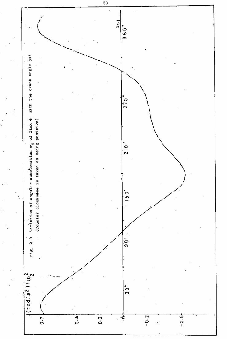
Variation of the angular acceleration of l i n k s 3,4,5 and 6 with crank angle i|f are shown in F i g . (2.8). F i g . (2.9), F i g . (2.10) and in F i g . (2.11). Variation of angular v e l o c i t i e s of l i n k s 3,4,5 and 6 with the crank angle ty. are given i n Fig. (2.12) for a crank speed of 2500 r.p.m. Ratio of angular velocity of the individual l i n k s to crank arm angular velocity i s shown in F i g . (2.13), for a complete revolution of the crank arm. A l l the kinematic values calculated above, are presented i n (Al)
for a crank speed of 2500 r.p.m.
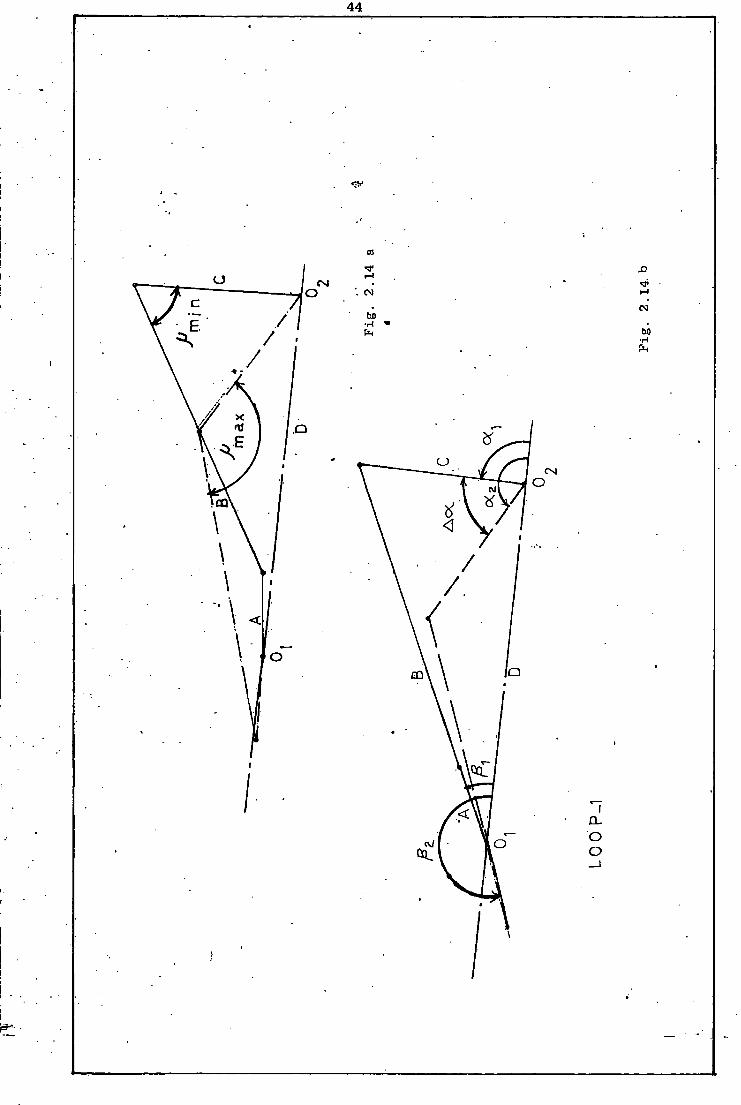
2.4 Algebraic Approach
The system i s separated into two loops, Fig. (2.14, a and b) F i g . (2.15)
The f i r s t loop represents a crank-rocker mechanism:, also known as a crank-
lever mechanism, which i s a popular type of the well known four-bar linkage
for converting continuous rotary motion to o s c i l l a t i o n . The second loop i s a
four-bar chain attached to the r i g i d l i n k 4 of the f i r s t loop at point C.
The two extreme positions of the output lever ( l i n k 4) of the f i r s t loop are
expected to occur when crank arm ( l i n k 2) i s in l i n e with the coupler. i
Proportions of the mechanism s a t i s f y Grashoff's c r i t e r i o n as in the following:
Base l i n k ^coupler + (output lever-driving crank)
4.8 <" 5.3
Base l i n k ^ coupler - (output lever - driving crank)
4.8> 3.1
Let A,B,C and D be lengths of input crank, coupler l i n k , output lever, and
base l i n k of the f i r s t loop, F i g . (2.14a) O , ff2 = a n S l e s showing dead-centre positions of output l i n k
Aff = o>2 - m1
A 6 = 0 2 ~ '01 ~ TT
the unit of angles being i n degrees.

CO. U
S-l CO
38
Q_ O I CO
•H in a
a> r-i ho c co
a c
H o
a>
•p .
s: p •H
TP
> c • H
•H P i-i •H in o o a
* r bO b c
•H c o
•H .P m •TO CO
a) c .>-< (0
o CO o p co
U) •i •H
CD i - l a> 3 U) bO -6 G CO
o ! H o o 1-1 o c o u •H <D
. P p CO c
•H 3 * h o
CO o
> Oi CN
h i •H
I™ CM 3
I'M
XJ
X \ \
o CM
\
\ o \
\ \ \
o in
/
/ /
o
/ , o
r -t o
o CM O
CN O I
I D
O I
39
40
in
CD
ft t-JO
CO
G)
ft
CD
10 eg 0)
cq CO p
in
TO CD
0) CO UP)
CO 10
(!) so - H CO
CD Cu
CD
CM
t>0
evi CSI
tn

[/)
u O u CD -•—> C D O u
0» n
a •4—»
If) CL If) a: c o o > O — LD u CNJ
'<7i II v_ o a v . Q.
U) t, J£
C jf a V—
u
CO LU > tr ZD u

42
so TO
CN 5
CM CN 5 $
LO CD
\ \
\ o CO CO X CN X CO
X /X. ; x X /
X o \ o X CM X
X X /
CN / \ O i
/ CD / /
o
X o X CD \ / o o CD LD
o o o o o
43
By using complex algebraic notation, the displacement equations can be
expressed as;
i fl. ±oij (A + B) e = D + C e (2.15)
iB2 i(02 " TT) iog Ae + Be = D + Ce (2.16)
equating r e a l and imaginary parts of equations (2.15) and (2.16) respectively;
(A + B) cosg 1 - C cosc^ = D (2.17)
(A + B) s i n p x - C sinofj = 0 (2.18)
(A - B) cos0 2 - C cosa 2 = D (2.19)
(A - B) s i n 0 2 - C sinor 2 = 0 (2.20)
from equations (2.17) and (2.18);
C sine?. D + C COSQT-A + B = = - (2.21)
s i n COSQJ.
from equations (2.19) arid (2.20)
C sino/g D + C coscv„ A - B = = (2.22)
sinf3 2 c o s B 2
from equation (2.21)
C 5 i n 9 l
sxn (a1 " B x)
from equation (2.22)
C sing
D s i n ( a 2 - p 2)
equations (2.23) and (2.24) are combined to give;
(2.23)
(2.24)
44
CO
CM CM
CM ho
bO /
.1
/
8"
\ CN o
CD
/ / I
CD
o
_J

45
ID
01
in
in
•j)
0)
3)
CM W)
\
I I I
in O
«T3 i - cn
46
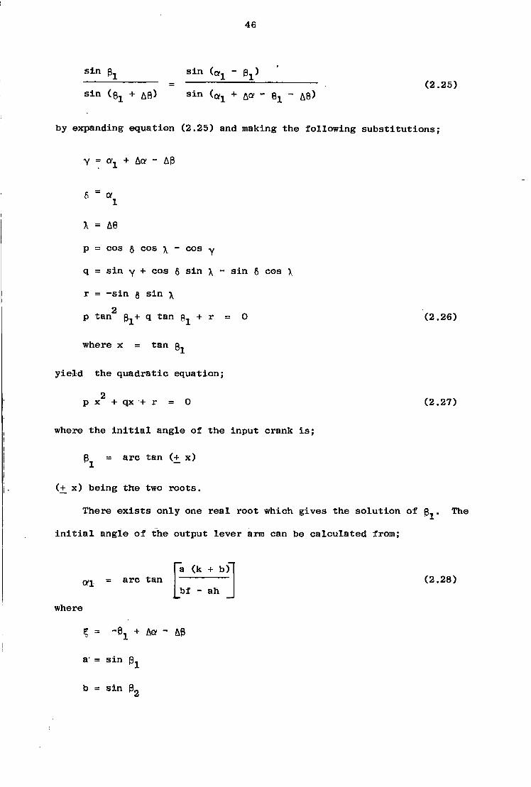
s i n 0 s i n - 0 X)
s i n ( e i + A s ) s i n (Q^ + & Q R - ^ - A B ) (2.25)
by expanding equation (2.25) and making the following substitutions;
Y = ffj + Ac? - AP
6 = Q f l
X = AS
p = cos 5 cos \ - cos Y
q = s i n y + cos 6 s i n \ - s i n 6 cos \
r = - s i n g s i n \ 2
p tan q tan + r = 0
where x = tan 3^
y i e l d the quadratic equation;
2
p x + qx •+ r = 0
where the i n i t i a l angle of the input crank i s ;
(2.26)
(2.27)
3, arc tan (+ x)
(+ x) being the two roots.
There e x i s t s only one r e a l root which gives the solution of Sj
i n i t i a l angle of the output lever arm can be calculated from;
The
<*1 arc tan a (k + b)
bf - ah (2.28)
where
Z = -0 X + Aa - A0
a' = s i n
b = s i n 0r

47
f = cos 0 h = cos ft
k c s i n 5
from equations (2.15) to (2.28), the following values have been calculated
for loop 1;
P 2 - 2 0 1 °
3, = 25°
ft o
«2 " 1 5 1
I t i s desirable to have the transmission angle d e v i a t i o n a s small as possibl
throughout the range of operation. The minimum permissible transmission
angle depends on the magnitude of the transmitted forces, j o i n t f r i c t i o n
and manufacturing tolerances. The extreme values of the transmission angle
are shown in F i g . (2.14 b). Prom .the c o s i n e law;
u, . = arc cos mm B 2 + C 2 - (D - A ) 2
2 BC (2.29)
= arc cos max
B 2 + C 2 - (D + A ) 2
2 BC
and .2 2 2 2 A + D = B + C
while;
C = i i n P l sxn
D or C = 02
(2.30)

48
A =
where;
s i n a. s i n au r = 1 r = ^ 1 2 s i n 0 X s i n p g
s 2 = s i n (» 2 - p 2)
substituting numerical values into equations (2.29) and (2.30)
u . = 62° nnin
(J-min — 1 3 4 °
Ap, ^ p, - p, , =72° max min
In order to have a smooth motion throughout the whole range of operation,
transmission angle i s o f t h e utmost i m p o r t a n c e . F r e u ' d e n s t e i n (1 ) n a s
shown that a good choice of transmission angle also coincides with minimum
^ overtones of the output lever, although a large transmission angle does
not n e c e s s a r i l y guarantee low fluctuation of torques. The force transmission
from the coupler to the output lever i s i d e a l l y e f f e c t i v e when the transmission o o angle i s nearly 90 or deviates as l i t t l e as possible from 90 . A good
discussion of the equations and procedure applied above are given in ( 1 ) .
Dead-centre positions of l i n k 6 and l i n k 4 are shown in F i g . (2.15). Variation
of the transmission angle, yum, with crank angle p s i has been presented i n
F i g . (2.6). O s c i l l a t i n g motion exercised by l i n k 4 i s transferred to l i n k
6 via the intermediate l i n k 5.
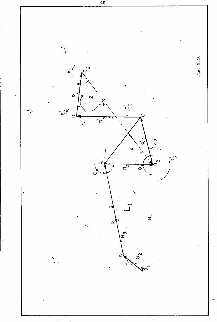
2.5 Application of Raven's Analysis
As shown i n F i g . (2.16) each l i n k i s replaced by i t s position vector.
Two seperate reference frames have been taken, x-y and x^-y^ corresponding
to two seperate but dependent loops, loop 1 and loop :2, writing the summation
law for the f i r s t loop, gives
49
+
CO
CM
CO CD
\ \
or r CO v y CD y \ -7" CD
a:
I CD CM CD
CD
co — I or
or
00 CP
CD

50
R + R 2 + R g + R 4 = 0 . (2.31)
Transforming to complex notation,
5 + r 2 e + r 3 e
In d i f f e r e n t i a t i n g eq. (3.31a)
r^e + r 2 e + r 3 e + r 4 e = 0 (2.31a)
j r 2 0 2 e + jr 3Gge + j r ^ e = 0 (2.32)
r^» r2» r3» r4 and 0^ are constants. • » 0
Letting 9 2 = uig , 9g = u)g and 9 4 = u>4 , gives
19 2 J 63 J e 4
j r 2 u ) 2 e + jr 3U)ge + j r ^ e = 0 (2.32a)
Equation (2.32a) contains the following quantities;
VA = r2u^' VBA = '3*3' VB = W
and i s the solution of the equation
V B = VA + V
After a transformation to complex rectangular notation and a separation of
the r e a l and imaginary terms eq. (2.32a) becomes;
r2 t u2 c o s 0 2 + X3W3 c o s Q 3 + T4W± c o s 9 4 = 0 ( 2.33a)
2 ® 2 s i n 0 2 - r 3 u ) 3 sin0g - r ^ s i n 9 4 = O (2.33b) - r,
The unknown quantities i n equations (2.33a) and 2.33b) are^g and ^ .
Since there are two equations and two unknowns, UJ„ and m. can be determined.
By d i f f e r e n t i a t i n g equation (2.32a), using a uniform angular velocity
of 2, gives
.2 • . 2 . . J 3 .2 « J 3 . « J 4 .2 • 4 0
J r2a>292° + J ^ S 6 + j r 3 ° 3 % e + + 3 W4 9 = °
(2.34)
51
2 . • = Q n where j = -1 and ^ = Qf
2 j e 2 j e 3 2 j e 3 ^ ^ - TgUJg e + j r <* e - r ^ e + r ^ e - r4<o4 e = 0 (2.34a)
the terms a r e i d e n t i f i e d a s ;
r 2 a a = r2<«2
r 2 3 B A = r3 U J3
r 2 A B ~ r4t«4
A B A T = r3,«3
V = r4 f f4
a * = 0 a
equation 2.34a corresponds to the vector equation,
AT.* + A „ R = A.* + A , R + A,,.* + A.r. . B B A A BA BA
corresponding t o t h e a c c e l e r a t i o n p o l y g o n .
using the equation
J 9 e = COSQ + j s i n 9
equation (2.34a) can be transformed into complex rectangular notation.
Separating the re a l and imaginary terms gives;
- r 2 u ) 22 cose 2 - r 3cv 3 sinOg - r ^ 2 cos0 3 - s i n 9 4 r ^ 2 cos0 4 = 0
(2.35a)
2 2 2 " r2Sfe S i n 9 2 + r 3 a 3 c o s 9 3 ~ r3{D3 s i n 0 3 + r 4 a 4 c o s 8 4 " r ^ s i n 9 4 = 0
(2.35b)
52
the only unknowns i n equations (2.35a) and (2.35b) are Q?3 and Q >4. The
simultaneous solution of these equations u t i l i s i n g determinants y i e l d
values of a and o^-
Writing the summation law for the second loop gives,
„ 1 1 1 1 R l + R 2 + R 3 + R4 = °
Transforming to complex notation 1 1 1 1
x J Q 1 x J Q 2 J6"3 J9.4 r, e + r. e + r_ e + r . e = 0 (2.36) 1 2 3 4
1 1 1 1 ^ 1 ^ where , , , r^ and 9^ are constant
d i f f e r e n t i a t i n g equation (2.36) gives 1 1 1
J 9 2 J 0 3 J 94 j r 2 0 2 e + j r 3 °Q3 e + e = 0 (2.37)
0 1 Letting 0 U ) 4
n 1
6 3 = w5
' 1 4 6
J82 1 J03 1 j e 4 X
J ' 2l u ) 4 e + j : r 3 l u ) 5 e + J r 4 l t B 6 e = 0 (2.37a)
equation (2.37a) contains the following quantities;
V c = r 2 ^ 4
VDC =
VD = U \
and i s the solution of the equation
V = V + V D C DC

53
After a transformation to complex rectangular notation and a seperation of
the r e a l and imaginary terms eq. (2.37a) becomes;
1 1 1 1 1 1 / n 0 0 . R
2 U ) 4c o s e 2
+ R3 U ) 5 C O S e 3
+ R4 « M 6
c o s e 4 = 0 (2.38a)
- r2
1 ( B 4 s i n 9 2 1 ~ r 3 1 ° l > 5 s l n e 3 1 ~ r 4 l u ) 6 S i n B 4 1 = ° (2.38b)
The unknown quantities in equations (2.38a) and (2.38b) are (u_ and u)e • 5 o
Solving them simultaneously gives o)§ ^nd (0g- D i f f e r e n t i a t i n g equation
(2.37) gives;
1 1 1 1 1 J 02 ^ 2 ^ 3 ^ 3
. 1Q 1 1«1 2 . l " 1 1«1 2 . 1'* 1 J r 2 62 6 " r2 9 2 6 + J r 3 9 3 6 " r3 9 3 6 + J I 4 94 G
1
where i : i 2 0 2 = ff4 9 2 = (n4
B 1 a fl1 2 - in 2 93: = 5 9 3 " '"s
e 4 i = « 6 01 42 = ^ 2
, 1 . 1 . 1 . 1 .1 . 1 J 9 2 1 2 J02 , 1 J0.3 1 2 J 9 3 . 1 a
J f i 4 J r 2 a 4 6 " r2 ^ 6 + J r 3 a 5 e • r 3 ""S 6 + J r 4 ff6°
1
- V ^ 4 = ° < 2 - 4 0 )
the terms are i d e n t i f i e d as;
r 1 2 a c ~ r2 «4
t 1 a c = r2 «4
r 1 2 — r
DC 3 «5
54
t 1 Dc " r 3 a5 r 1 2
aD = r4 <»6 t 1
3D = r4 a6
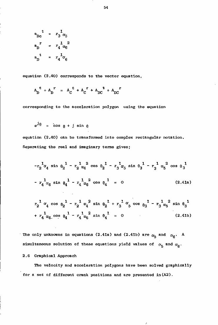
equation (2.40) corresponds to the vector equation,
A * + A r = A * + A „ r + A * + A * D D C C DC DC
corresponding to the acceleration polygon using the equation
e J9 = cos 0 + j s i n 9
equation (2.40) can be transformed into complex rectangular notation.
Seperating the r e a l and imaginary terms gives;
- r 2 a 4 s i n 9 2 - r 2 ^ cos 9 2 - r g ^ s i n 9 3 - r 3 ^ cos 9 3
" S i n 9 4 X ~ T<k®G C O S ^ = ° (2.41a)
1 1 1 2 . 1 1.. 1 1 2 . . 1 r 2 cv4 cos e 2 - r 2 ^ s m 9 2 + r g a g cos g 3 - r g ^ s i n 9 3
+ ' ^ f f e - 0 0 - 8 9 4 X " r 4 1 ( U 6 2 S i n 9 4 X = 0 (2.41b)
The only unknowns in equations (2.41a) and (2.41b) are a 5 and a^. A
simultaneous solution of these equations y i e l d values of ov and oia.
2.6 Graphical Approach
The velocity and acceleration polygons have been solved graphically
for a set of different crank positions and are presented in(A2).

55
2 . 7 Energy variation of the system
The t o t a l k i n e t i c energy of the system at any instant i s composed of
the k i n e t i c energy of translation about the mass centres of the li n k s and
the k i n e t i c energy of rotation about the mass centres of the l i n k s and
shafts. This can be expressed as i n the following form;
2 2 2 2 2 2 2 Total k i n e t i c energy = \ T I Q J U ) + I 3u> 3 + I 0 2 u 5 4 + I4t"4 + I5^5 + I6 U )6 + I 0 3 U J 6 ^ 1
2 2 2 2 2 + 4 Tm-V _ + m_V _ + m.V . + m_V + m„V 1 ( 2 AO\ 2 2 g2 3 g3 4 g4 5 g5 6 g6 1 K*.**)
where V , ' = l i n e a r v e l o c i t i e s of the mass centres of the corresponding gl-»6 l i n k s
2 2
in equation ( 2 . 4 2 ) IQ^OVJ A N ° " M 2 VG 2 a r e c o n s t a n t s (since cv = 0 ) . The var
i a t i o n of the k i n e t i c energies due to rotation of shafts 0^, 0^, l i n k 4 and
link 3 with the crank angle as shown in F i g . 2 . 1 7 . The t o t a l k i n e t i c energy
due to translation i s negligible i n comparison with the k i n e t i c energy due
to rotation. Therefore equation 2 . 4 2 can be reduced to;
2 2 2 2 2 2 Total k i n e t i c energy? K I
3 0 ) 3 +- , I
0 2«>4 + I4")4 + I5«»5 + I6 U )6 + I03 U )6 ^ + C
where C = \ I
( 2 . 4 3 )
2
01«2
variation of the t o t a l k i n e t i c energy (excluding C) with the crank angle i s
shown in F i g . 2 . 1 8

56
B CO V)
M 9
CM co i «-> CO
0 e m to
e c u O CB
ro CS CO c c ( Y°
«
ro
\ / I
i
\ CNJ
e n
c 4 6)
if) CM CM

5 7
F i g . 2.18 V a r i a t i o n of the k i n e t i c energy w i t h the crank angle
/
\
1 crank speed= 2500rp. A=3.712
1 I
\ \ \ / / \ 1/
pS| i i 300" 360° 90° 210'

58
Chapter 3 Force and S t r e s s A n a l y s i s 3.1 Kinetostatic Approach
The motion of the mechanism i s completely specified and the. purpose
i s to compute the bearing reactions, shaking forces, shaking moments as
well as the forces and the torque required to produce the motion. The
s i z e , shape and material of each l i n k are known. The i n e r t i a forces
are taken as i f they acted at a point on the l i n k s , although they are
distributed along the l i n k s and are not concentrated at one point. In
the following analysis the concern i s only with the forces at points
where the l i n k s are paired with other l i n k s . These forces are treated
as external forces on the l i n k s . The shapes of the l i n k s are assumed to
be r i g i d and the pin j o i n t s are considered to be f r i c t i o n l e s s . The
i n e r t i a e f f e c t s of the individual l i n k s , in comparison with the i n e r t i a
e f f e c t s of the shafts through 0 and 0 are reasonably negligible and
t h i s aspect of the dynamic analysis has been shown i n further steps.
However for a detailed dynamic analysis of the system, which i s beyond the
scope of the objective, the d i s t r i b u t i o n of the i n e r t i a forces along the
l i n k can be important. In most advanced engineering cases the stresses
due to i n e r t i a forces are determined by breaking the link into equal
length sections. The i n e r t i a force for each section i s determined from
the mass of the section and the acceleration of the midpoint of the
section which represents the d i s t r i b u t i o n of the i n e r t i a forces along the
l i n k (21 ) . In cases where the l i n k s are not of uniform cross section
the accuracy of t h i s approximation depends upon the number of sections
that the l i n k i s broken into. By increasing the number of sections a
greater accuracy can be achieved.
59
A solution to the dynamic force analysis of a four-bar planar
mechanism has recently been presented ( 4 ) , as a set of algebraic
equations. The forces along the li n k s 3 and 5 cause pure normal
stresses, and the normal forces cause bending st r e s s e s . In the actual
case the normal stress e s vary along the l i n k s because of the i n e r t i a
forces. The system has a single degree of freedom, the angular pos
i t i o n s of l i n k s 3, 4, 5 and 6, given by 0 g ( t ) =3, 0 4 ( t ) = y + 75°
0g ( t ) = x\ , and 0g ( t ) = 360° - upa, are functions of the angular
position 0 2 ( t ) = ty., and the length of the l i n k s . The lin k lengths
are denoted by 1^ , i = 2, 3, 4, 5 and 6, and each of the moving l i n k s
has mass , i = 2, 3, 4, 5, 6 and a moment of i n e r t i a 1^ with respect
to the centre of mass. The locations of the centres of mass of the
members are defined by parameters 1^ and 0^. The bearing reaction F ^ j
i s the force of member i on member j . The D'Alembert couple on lin k i i s ;
C 4 = r I . 0. i 11
The x and y components of the D'Alembert force being;
ix m. aj l i x
and
m. a. i i y
where a ^ and a ^ are the corresponding acceleration components of the
centre of mass of member i . The motion of the mechanism i s known and the
i n e r t i a loading on the system i s defined. T i s the external torque on
the input l i n k 2, required to produce the prescribed motion. The dynamic

60
equilibrium equations for the fi v e moving l i n k s y i e l d the following
system of f i f t e e n l i n e a r algebraic equations:
where
ti
where
D2x + F12x " F23x = ° ( 3 - 1 }
D2y + F12y " F23y = 0 < 3 2 > D3x + F23x " F34x = ° ( 3 ' 3 )
D 3 y + F23y - F34y = ° ^ ( 3 " 4 )
4x 34x 14x 45x
% + F34y + F14y " F45y = ° ( 3 " 6 )
D5x + F45x " F56x = ° ( 3 ' 7 )
D. + F - F = 0 (3.8) 5y 45y 56y
D + F - F = 0 (3.9) 6x 56x 67x D + F - F = 0 (3.10) 6y 56y 67y
C 2 = " h *2 C 2 = -hlk
C 2 = " ( I 2 + m 2 r 2 + V \
*01 = M o m e n t °* i n e i " t i a °f the driving shaft through 0^
C - D r s i n 0 + D r cos 0 + T + F 1 s i n 0 - F 1 cos0' 2 2x r2 v2 2y 2 ^2 2 23x 2 ^2 23y 2 2
op C = - 1 0 3 3*3
C 3 " D 3 Xr 3 S l n 0 3 + D 3 y r 3 C ° S 0 3 + F 3 4 x 1
3S i n 0 3 " F 3 4 y 1
3C ° S 0 3 = °
c4 = - 1 A C' = - I 0 4 02 4
I „ = Moment of i n e r t i a of the shaft through 0 Oa 2
C4 = - ( I 4 + V 4 + I O 2 ) 0 4
61
where
C \ ' " D / l r y l S l n ^ / l + 9/1 > + D / l T A C O S (0/1 + 9, > 4 4x 4 4 4 4y 4 4 4
- F_. l . s i n 0. + F_. 1. cos 0. - F.._ 1. s i n 0* 34x 4 4 34y 4 4 45x 4 4 + F,. 1, cos 0! = 0 (3.13)
45y 4 4 C = - I 0
5 5*5
C 5 " D 5 x r 5 S i n 0 5 + D 5 y r 5 C O S 0 5 + Ws81" 0 5
-F56yhC°S05 = ° (3-14>
C 6 = -h*6
°6 =
I Q g = Moment of i n e r t i a of the shaft through 0^
C 6 = " ( I 6 + m 6 r 6 2 + I 0 3 ) 0 6
C 6 " D 6 x r 6 S i n < ' 0 6 " D 6 y r 6 C O S 0 6 " F 6 5 x L 6 S i n 0 6
+ F 6 5 y 1 6 C ° S 0 6 = °
(dot denotes d i f f e r e n t i a t i o n with respect to time t )
The configuration of the mechanism and the free-body diagrams are
shown i n Fig.(3.1-3.2) f o r 0 g ( t ) = . ty. = 50°. Relations of the form
F ^ ^ = ~ F34x' e t c , » n a v e D e e n employed in the formulation of these
equations. The shaking force F g J i s the resultant force on the frame.
The x and y components of the shaking force are;
F = F + F + F = -F - F - F sx 21x 41x 67x 12x 14x 76x
= D2x + D3x + °4x + D5x + D6x ( 3 " 1 6 )
and
F = F + F + F =-F - F - F = sy 21y + r41y 67y *12y *14y r76y
D_ + D 0 + D + D_ + D c (3.17) 2y 3y 4y 5y 6y

62
o
(D
\
\ LO
CN -O CD CD •-J
\ \
ro \ \ \ \
rxJ ro
01 CM CN

64
The shaking moment M about an a r b i t r a r y point 'p' on the frame Fig. sp
i s
M s P = " T2 " F 4 1 x e i S l n *1 + F 4 1 y e i C O S h
- F21x e2 S i n *2 + F21y e2 C O S *2 " F67x 63 S ± n *I
+ F 6 7 y e 3 C O S *3 ( 3 1 8 )
The effect of gravitational p u l l on the l i n k s has been neglected.
The compressive and/or t e n s i l e forces ac.ting on the l i n k s can be
determined by resolving the forces acting on the l i n k s along themselves.

65
3.2 - Application of V i r t u a l Work Method to the Mechanism
Energy methods can be used to short-cut the previous kine t o s t a t i c
approach. The following solution, u t i l i s i n g the method of v i r t u a l work
introduces greatest timesaving to the analys i s . The main advantage of the
method i s that, i t eliminates the l i n k - t o - l i n k treatment, and permits
an examination of the whole system at one time. A good discussion of
thi s method i s given in (8), and ( 9 ) .
For any mechanism composed of n members, the method of v i r t u a l work i s
written:
T . 0- + F .V + (-m A '.V ) n n n n n Gn Gn
• < - v „ ^ > = ° < 3 - w )
which can normally be solved for one quantity. Since the terms are vector
quantities, the solution includes both the magnitude and direction of the
unknown. I t s major disadvantage i s that s i n c e eq 3.19 c o n t a i n s only
the a p p l i e d f o r c e s and torques, i t can not be used to solve for internal
forces or the reactions between members of the mechanism.. Formulation of
eq. 3.19 u t i l i z e s an imaginary small displacement of the mechanism, being
consistent with the constraints of the mechanism. The work done by the
v i r t u a l displacements i s referred to as v i r t u a l work and i f the system
i s in s t a t i c equilibrium under the action of the applied forces and
torques then the work done with a v i r t u a l displacement i s zero.
Application of eq. 3.19 to the mechanism yie l d s .
66
T 2 °2 + ( " m 2 a 2 - V 2 ) + ( " m 3 V V + < _"4 V V + ^sVV + (- m6 V V + ( _ I 3 a3 °3 } + + [ _ ( ( I 4 + m 4 r 4 2 ) <*4 ^
+ ^ ( ( I 6 + m6 r 6 2 ) + I 0 3 ) *6 = ° ( 3 ' 2 0 )
F V = 0 n n
Substituting the appropriate values for 'ijr' equation (3.20) i s
used to calculate the external torque T . In the formulation of equation
(3.19) the gravitational effects are neglected. A modified form of t h i s
equation taking account of gravitational e f f e c t s i s given i n ( 8 )
3.3 The Power equation
The power equation for the system can be written as;
T2 mj " T6(J06 = T ( U (3.21)
where
T = external torque applied on input l i n k 2
T = the torque transmitted by DO o o Tu) = power necessary to accelerate or to decelerate the system
^ = angular velocity of the shaft to which torque T i s referred
Equation (3.21) corresponds to the dynamical r e l a t i o n :
Rate of work done by external forces = Rate of change of k i n e t i c
energy of the system
or a l t e r n a t i v e l y :
Rate of work done by external forces = Rate of work done by ef f e c t i v e
forces
The variation of the.torques transmitted by r i g i d l i n k 4 and DO^ are shown
i n Fig.(3.3) and i n Fig.(3.4 ) . The corresponding transmitted power i s
shown in F i g (3.5 )

67
E a
x ' C c •H O -< o
l O tj (N •H bO II •H Sj T J
•O a> a> p in :>> £ c
ca <D O (J w •H -H E m (n a c
a 0
a as C7 .M H C O to ' O
b o
CL
o I CD I m
a
ca •H
n /
O O cn
•rl o .to r s i
/
/ \ \
/
O o
o S.
i
C
n
E in c 03
X X o CO
O CD
O •vf
O O O
X "5"
\ i •
o CD
I .
CD
•
C
ro O Q >> n T3 0)
E 0) c
o
cr
o o lO CM
O a in
o
d o
re
05
•a o •H a
•H
hi. •H
to CXI O
i
70
3.4 Graphical Approach
At any i n s t a n t the motion o f any i n d u v i d u a l l i n k i s equivalent t o the
r o t a t i o n of the l i n k as a Vhole about a f i x e d p o i n t i n space. By determining
instantaneous centres of r o t a t i o n , (as shown i n .Figure (3.6 ) g r a p h i c a l
f o r c e a n a l y s i s ) , , i t i s possible t o determine the dynamic forces
a c t i n g on the mechanism. A d e t a i l e d a n a l y s i s o f t h i s procedure i s presented
i n ( 2 1 ) , ( 1 4 ) , ( 1 2 ) , (13) and ( 3 ) .
R e f e r r i n g t o F i g . ( 3 . " f f ) , 0 ab 0 and 0 cd 0 can be t r e a t e d as two
separate but dependent four-bar chains, I and I are the l o c a t i o n s of the
instantaneous centres of r o t a t i o n . Both the l i n e a r v e l o c i t y of the mass
centres and the angular v e l o c i t y of r o t a t i o n vary from i n s t a n t t o i n s t a n t .
The l i n e of a c t i o n o f the fo r c e a p p l i e d t o the l i n k s does not pass through
t h e i r mass centres. The i n d i v i d u a l l i n k s are constrained t o move i n a
d e f i n i t e way by the adjacent l i n k s t o which they are connected, and the
r e s u l t a n t of a l l the forces applied through those connections i s equal t o
the f o r c e r e q u i r e d t o accelerate the l i n k , the e f f e c t i v e f o r c e R . The
magnitudes o f the e f f e c t i v e f o r c e i s replaced by another f o r c e equal t o
-m. a .., displaced from the mass centre a distance h.. This f i c t i t i o u s i c g i x fo r c e replaces the combined e f f e c t s o f the i n e r t i a torque and the i n e r t i a
f o r c e , ab i s a l i n k w i t h pins a t A and B, constrained t o move along the
paths shown. Since the weight of the l i n k s i s small i n comparison t o the
other forces which act on the l i n k , the e f f e c t of g r a v i t y i s
ignored as p r e v i o u s l y . The magnitude and l i n e s o f a c t i o n of R i s
determined. A s i m i l a r procedure i s a p p l i e d t o l i n k cd. The f o r c e F^ which
i s a p p l i e d t o the l i n k AB a t p i n A, by the crank arm O A w i l l have a
component F \ t a n g e n t i a l t o the path of A and also a component F i n perpendicular t o the path o f A. F does the u s e f u l work on the l i n k . F a a i
constrains the pin.. A t o f o l l o w the given path. This assumption i s
s i m i l a r l y v a l i d f o r the forces a c t i n g at b,c and d:. By c a l c u l a t i n g the


72
component i n the t a n g e n t i a l d i r e c t i o n , the component i n the normal d i r e c t i o n
and. the two other components a c t i n g on the next p i n are found from the
e q u i l i b r i u m c o n d i t i o n s of the l i n k , namely, the vector sum of a l l the forces
which act on the l i n k being zero, and the a l g e b r a i c sum of the moments of
the forces about any p o i n t din t h e i r plane being zero. Components of F , a
F , F and F , normal t o the paths of a, b, c and d are known. For l i n k b e d ab, the moments are taken about I , the p o i n t of i n t e r s e c t i o n of the l i n e s
of a c t i o n of F and F and f o r l i n k cd, about I , the i n t e r s e c t i o n b a 1 of the l i n e s of a c t i o n of F and F The equations f o r F * and F *
c d b d aire then
F 1 = "CM } R 3 ( I 2 X ) (3.22)
F d
<M 2>
i R 5( z I ) "
( d i x ) (3.23)
where
R 3 = m 3 3g3 h 3 = ha3 " R3
R 4 = - m4 3g4 h 4 =
" R4
R 5 = " m5 ag5 h 5 = V 5 " R5
R e = - r a6 a
g 6 h e = V e
• " R6
The moment o f i n e r t i a values f o r the s h a f t s are included i n the above
expressions as a p p r o p r i a t e l y . A f t e r the magnitudes of » F^^^, a n d F** are obtained by drawing the f o r c e polygon. The torque which must be d a p p l i e d by the crank arm O^a, to the whole system, i n order t o overcome
the combined e f f e c t s o f i n e r t i a i s given by the product F 0 a. a l
73
As i n the e a r l i e r s e ctions, the crank i s assumed t o r o t a t e a t constant
angular v e l o c i t y
3.5 S i m p l i f i e d Force A n a l y s i s
As mentioned i n s e c t i o n 3.1 n e g l e c t i n g the i n e r t i a e f f e c t s o f l i n k s
3,4,5 and 6, which are r e l a t i v e l y small i n comparison w i t h the .
i n e r t i a e f f e c t s of s h a f t s through 0 and 0 , the f o r c e a n a l y s i s can be
s i m p l i f i e d t o a l a r g e e x t e n t . From Fig.(3.7 ),the f o r c e a p p l i e d t o l i n k
5 by l i n k 6, F , i s determined by t a k i n g moment about 0 o 3
T 6 = - W * 6 = F 5 k l ( 3 ' 2 4 )
where k^ = Moment arm
from equation (3.24)
F 5 =
k l
Repeating the same procedure f o r 0
_ ID2 «4 + F 5 k 2 + F 3 k 3 = ° ( 3 ' 2 5 )
F 5 1 = " F5
F 3 X = " F3
from equation (3.25)
F 3 = I02°'4 " F 5 k 2 k 3
Torque r e q u i r e d t o d r i v e the mechanism i s then,
T 2 = F 3 k 4
Although the a n a l y s i s presented above does not give very accurate
r e s u l t s , i t o f f e r s a quick and reasonable method t o determine the a x i a l
l o a d i n g range on l i n k s 3 and 5.

74
CO
P CO
CO
Li) in L l . I D IX) LL-
CM I CO u :
CM
CO L L , CO
CO bD
CO
I I CO
CO
o
75
3.6 Stress An a l y s i s
The a x i a l s t r e s s v a r i a t i o n f o r l i n k s 3 and 5 are determined from;
a = ^AX a n d a _ F3AX 5AX A 3AX A_
From F i g . (3.9) and (3.10) -5 2
A^ = cross s e c t i o n a l area . - l i n k 3 - BB = 10 x 14.95 m _5 o
A 2 = cross s e c t i o n a l area - l i n k 5 - CC = 10 x 6.32 m
The l i n k s do not have a uniform c r o s s - s e c t i o n a l area thus a x i a l s t r e s s
v a r i e s accordingly. Stresses are p r o p o r t i o n a l w i t h the square of the crank
speed. V a r i a t i o n of a x i a l stresses f o r A and A are shown i n F i g . (3.7;) J. £»
f o r a complete c y c l e , a t a crank speed o f 2500 r.p.m.
The peak t o peak (maximum t o minimum) s t r e s s values are r e f e r r e d t o
as st r e s s range, and the v a r i a t i o n of t h i s range w i t h respect t o the square
of the crank-arm angular v e l o c i t y i s given i n F i g . ( 3 . 8 ) . Plane bending
s t r e s s values f o r the same cross-sections o f l i n k s 3 and 5 can be c a l c u l a t e d
from M_y . F _ . \ l /2) y _ ? 5 Jc5 _ 5b \ 5 Jc5 , . /
a = ~1 " 7 l (3.26) 5b c5 ^ " c5
where y , = distance from the n e u t r a l a x i a l - c r o s s - s e c t i o n CC Jc5 I _ = Moment of i n e r t i a of the cross-section CC c5
and
0- = - S - b l = 3b 3 b3 (3.27) 3 b XB3 ^ 3
where y^„ = distance from the n e u t r a l a x i s - c r o s s - s e c t i o n BB bo I„„ = Moment of i n e r t i a o f the cross-section BB
and F = f o r c e component a c t i n g normal t o l i n k 5 5b F = f o r c e component a c t i n g normal t o l i n k 3 3b
76
110 N/m
100
i * i \ / \ /
/ • \ \ 7 \ / \ / \ / 20
7 o I
A 200 100 300
I V
ink o
l i n k 3 60
/
/
/ /
110
F i g . 3.7 V a r i a t i o n o f a x i a l stresses i n l i n k s 3 and 5 w i t h the crank angle (crank speed = 2500 r.p.m.)
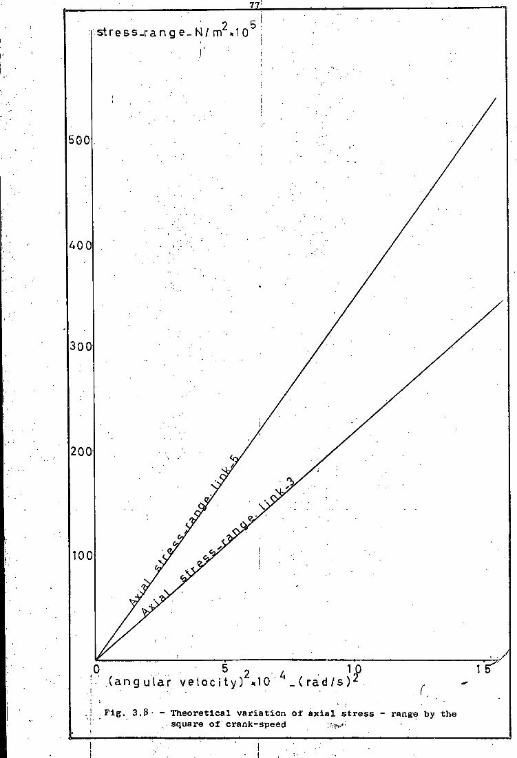
77
s t r e s s _ r a n g e _ N / m « 1 0
i
500
4 0 f l
3 0 0
200
100
10 ( r a d / s ) 2 ( a n g u l a r v e l o c i t y ) *10
f
F i g . 3.9 T h e o r e t i c a l v a r i a t i o n o f a x i a l s t r e s s range by the square of crank-speed

78
The l i n k s are t r e a t e d t o be beams of non-uniform c r o s s - s e c t i o n , and
magnitude of s t r e s s and d e f l e c t i o n i s assumed t o be d i r e c t l y p r o p o r t i o n a l
t o the load.
Resultant s t r e s s over a cross-section i s then given by:
nax My cn
- I cn (3.28)

79
LINK 3-connecting rod
,-D=U.985
T 22.5 L
A +B *
7 n B.B cross.sAA
Oi e >0 r
D = 22 69.2
i
A l l dimensions are i n mm
F i g . 3.9 Link 3

!
so;
LINK-5
f ron tv iew
i
cross s e c c c
scale. x2 !
• F i g . 3.10

81
0
0 01
0)
0> i n
a ii
ho
CD C3 10
a> 0)
in •H
CO
to CNJ
V. \ o
to
CM
<r /vi i O ^ <r to 0 4 i i ^ i i
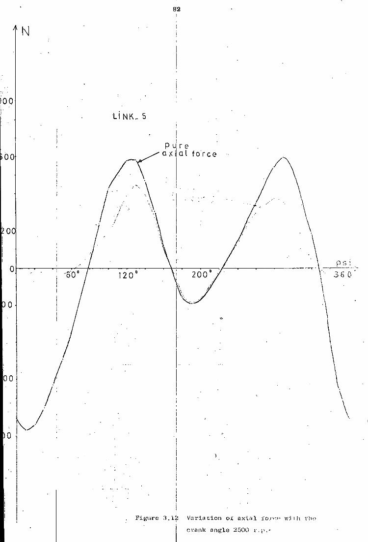
82
11 NK- 5
P 'J| r e a X i! a I f o r c e
Figure 3.1JS V a r i a t i o n o i axin.l crank angle 2500

83
P u r e a x i a l f o r c e
200° .1 00
/ \ ./
2500rp
LINK-3
Figure 3.13 V a r i a t i o n of a x i a l f o r c e a t crank angle
I
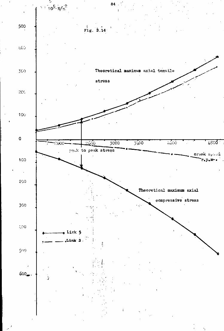
84 1 aJ- W:
500 F i g . 3.14
i.
Theoretxcal maximum a x i a l t e r t s i l 500
s t r e s s
10C
.'•DO 3000 -.000 to peak s t r e s
100 r.p.mr •
200
Theoretical maximum a x i a l
compressive s t r e s s 300
Link 5
Link 3
6 0 0 -

85
Chapter 4
Instrumentation, Experiments and Experimental Results
4.1 Instrumentation
The s t r a i n gauge i n s t a l l a t i o n and a n c i l l a r y equipment i s shown i n
Figs. ( 4 . 1 ) , ( 4 . 2 ) , P l ate (4.1) and P l a t e ( 4 . 2 ) . Each p a i r of gauges i s
w i r e d i n various c o n f i g u r a t i o n s on the extension box t o measure
only a x i a l . and only . bending (z d i r e c t i o n ) s t r a i n s . The
output from the extension box i s fed i n t o the c a r r i e r - a m p l i f i e r where
a (met re i S used i n con j u n c t i o n w i t h the balance knobs on the extension ^»»
box t o balance the bridge c i r c u i t . The output from the a m p l i f i e r i s fed
through a lead t o an u l t r a - v i o l e t recorder where dynamic records are
produced on p h o t o - s e n s i t i v e paper. To prevent f a i l u r e due t o overloading
r e s i s t e r s and a fuse are connected i n the leads t o the u.v. recorder. I f
a record was not r e q u i r e d i t was convenient t o d i s p l a y the response o f the
s t r a i n gauges on the o s c i l l o s c o p e t o examine the s t r a i n pattern.A s l o t t e d metal
d i s c i s attached t o the d r i v e s h a f t and an electro-magnetic pick-up u n i t
i s placed close t o the d i s c t o produce a v a r i a b l e voltage. This v a r i a b l e
voltage showed one b l i p f o r each r e v o l u t i o n of the s h a f t which i s recorded
by the u.v. recorder a t the same time as the t r a c e from the s t r a i n gauges
was recorded, which enabled the speed o f the s h a f t t o be determined, f o r
each recording. A variable-speed 2HP e l e c t r i c motor i s used t o d r i v e the loom
P l a t e ( 4 . 2 ) . The wires l e a d i n g from the t a g s t r i p s on the specimens t o the
extension box were p a r t i a l l y p r o t e c t e d by p l a s t i c tubes against f a t i g u e
f a i l u r e . I n order t o prevent damage due t o f r a c t u r e at h i g h o p e r a t i n g speeds,
a sheet s t e e l cover i s used over the combs. The basic p r i n c i p l e a p p l i e d i n
the design o f the dynamic measuring system i s t h a t the whole set-up w i l l
f a i t h f u l l y measure the s t r a i n no matter how i t v a r i e s w i t h time. Since
the s i g n a l from the strain-guage c i r c u i t s i s small a c a r r i e r a m p l i f i e r i s
engaged, which i s capable of r e c i e v i n g s i g n a l s i n the m i l l i v o l t range and
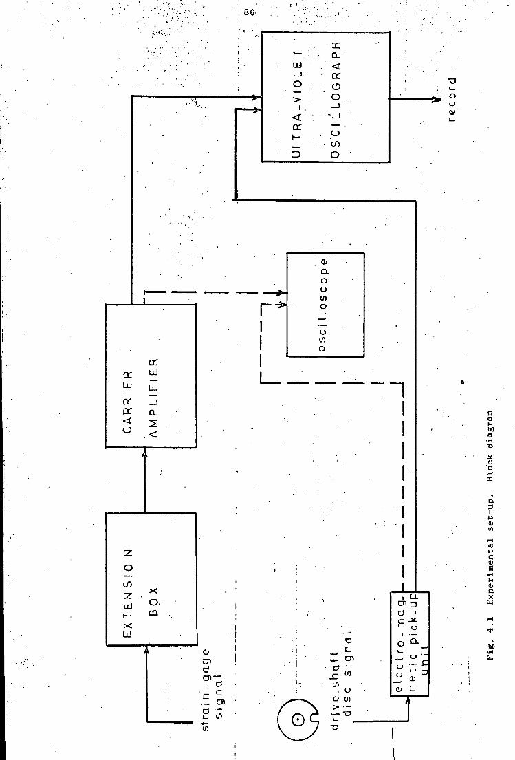
8&
X t — . : CL LU <
cc o o ' > •
1 _ l < ..._j • cr — •
i CO => o
o u
CC LU
LU U_
_ l cr Q_ < o <
i \
z
o
co X
LU o . t — X LU
CD
cn i
._ cn
if)
0> U)
1 CL cn r) a i £ u 1 o CL
< O — c
a> CD C
e a u M « •a
o o i-i m
3 I P
t-> c <D E •H o a •a w
bO •H

87
I
CO X LU
CO a O LU CO Q •7 CO UJ
co o CL CL
I 7;
o CO UJ LU
CO DC CO UJ 1 1
I UJ
GC fC LU
t—
LU
i l l
UJ
CO LU
UJ o cc or. u. cc O
to
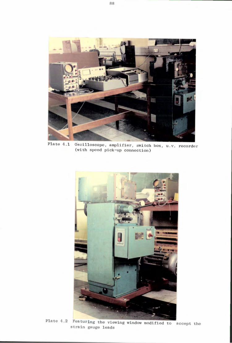
89
' 1
r
t i * Li I
P l a t e 4.1 O s c i l l o s c o p e , a m p l i f i e r , s w i t c h box, u.v. r e c o r d e r ( w i t h speed p i c k - u p c o n n e c t i o n )
s t r a i n gauge le a d s s t r a i n gauge l e a d s

89
ft
1 s i
i l l
r •r
I
P l a t e 4.3 2 HP E l e c t r i c motor and speed v a r i a t o r u n i t

90
of s u p p l y i n g a s i g n a l i n the v o l t range. The r e c o r d i s on s e n s i t i z e d paper
which r e q u i r e s no developing. A p o l a r o i d land-type camera i s f i t t e d to
the o s c i l l o s c o p e to photograph the experiemntal s t r a i n p a t t e r n . The r e s u l t s
a r e a l l taken from records produced by the u.v. r e c o r d e r . I t i s assumed
t h a t the only r e s i s t i v e elements i n the s t r a i n - g a u g e c i r c u i t a r e the gauges
themselves ( t h e presence of l e a d s which a f f e c t s e n s i t i v i t y and c a l i b r a t i o n
a r e n e g l i g a l a l e ) .
4.2 Elements of the Experimental Set-up.
1. C a r r i e r - A m p l i f i e r ; A U n i v e r s a l c a r r i e r - a m p l i f i e r , type 581 DNH-Peekel,
i s used. E l e v e n gauge f a c t o r s were a v a i l a b l e , ranging from 1.75 to 2.25,
w i t h an accuracy of 0.5%. H a l f and q u a r t e r - b r i d g e (120 Q) c i r c u i t s a r e
employed. There a r e s i x i n t e r n a l c a l i b r a t i o n v a l u e s , 30, 100, 300, 1000,
3000 and 10000 m i c r o s t r a i n . Bridge v o l t a g e i s 5 v o l t s , on the most
s e n s i t i v e range (3 JJ,S , f u l l - s c a l e d e f l e c t i o n ) f o r one a c t i v e s t r a i n - g u a g e .
The output g i v e s 1 v o l t f o r f u l l s c a l e of the metre and remains l i n e a r
f o r dynamic measurements even up to 10 v o l t s . The s p e c i f i e d a c c u r a c y of
the equipment f o r dynamic measurements i s + 0.75% f o r a l l ranges. Time
delay i s 0.5 ms f o r 5000 Hz. L i n e a r i t y of the r e c o r d e r output i s + 0.05%
f o r 2 v o l t s peak-to-peak output and + 0 . 1 % f o r 20 v o l t s peak-to-peak
output, provided t h a t the input i s balanced f o r c a p a c i t y . D r i f t i s approx
imately 1 p, s t r a i n / d a y
2. U l t r a - V i o l e t Recorder; A "Southern Instruments" u l t r a v i o l e t o s c i l l o g r a p h
10-100 s e r i e s i s used f o r continuous d i r e c t r e c o r d i n g of input s i g n a l s .
S i g n a l i s fed to a minature t u b u l a r galvanometer which r e f l e c t s a spot-.of
i n t e n s e u l t r a v i o l e t l i g h t onto the p h o t o s e n s i t i v e r e c o r d paper. The def
l e c t i o n of the galvanometer i s a f u n c t i o n of the amplitude of the i n p u t -
s i g n a l c u r r e n t . A c h o i c e of e i g h t paper speeds i s a v a i l a b l e . Two of the
input s o c k e t s a r e used. F i r s t one f o r the c a r r i e r - a m p l i f i e r o u t p u t - s i g n a l
and the second one f o r the e l e c t r o m a g n e t i c pick-up u n i t o u t p u t - s i g n a l . A

91
paper speed of 37 mm/s i s used f o r c a l i b r a t i o n w h i l e paper speeds of 111
and 333 m/s a r e a l t e r n a t i v e l y used dueing a c t u a l measurements. Four f i x e d
time i n t e r v a l s a r e a v a i l a b l e , 0.01, 0.1, 1 and 10 seconds, and the s p e c i f i e d
a c c u r a c y of t h e p r i n t e d l i n e s i s w i t h i n +• 2%. Paper speed s t a b i l i t y i s + 3%.
S i n c e , i n s t e a d o f pen-aim, an u l t r a v i o l e t l i g h t beam of zero mass i s i n t r o
duced, d i r e c t r e c o r d i n g o f f r e q u e n c i e s up to 10 KHz can be performed. SMI,
Type SMI/N, S e r . No. 1480-2 galvanometer i s employed f o r r e c o r d i n g .
3. E x t e n s i o n Box: A "Peekel 4-channel 4 UD" type s w i t c h box i s used.
There a r e four input channels, f o r f u l l - b r i d g e , h a I f - b r i d g e or q u a r t e r -
bridge, 120 o c o n f i g u r a t i o n s . Each channel has four b a l a n c i n g c o n t r o l s ,
t h r e e f o r r e s i s t i v e b a l a n c i n g and one f o r c a p a c i t i v e b a l a n c i n g of the
bridge c i r c u i t . The s p e c i f i e d t y p i c a l e r r o r of s w i t c h c o n t a c t s i s 1 - 2
m i c r o s t r a i n . Ranges of r e s i s t i v e and c a p a c i t i v e b a l a n c i n g a r e + 6000 p,s
and + 1000 pf r e s p e c t i v e l y .
4. O s c i l l o s c o p e : A cathode ray o s c i l l o s c o p e i s employed to d i s p l a y the
r a p i d l y v a r y i n g s t r a i n waveform. S i n c e the output of the s t r a i n gauge
c i r c u i t i s connected to v e r t i c a l a m p l i f i e r s , v e r t i c a l d e f l e c t i o n i s r e l a t e d
to s t r a i n . The i n t e r n a l sweep c i r c u i t a l l o w s the t r a c e to be d r i v e n h o r i
z o n t a l l y a t a p r e s e l e c t e d r a t e .
4.3 S t r a i n gauges and gauge i n s t a l l a t i o n s 5 i
S i n c e s t r a i n gauges a r e used to measure v a r y i n g and repeated s t r a i n s ,
s p e c i a l c a r e i s e x e r c i s e d i n gauge s e l e c t i o n , i n gauge bonding and i n l e a d . *
attachment. "Timsley, T e l c o n " elements type 7/120/EC, of d i f f e r e n t batch i
numbers, gauge f a c t o r = 2.18 Range = 120 q + 1%, electrical..' s t r a i n gauges a r e
employed. The r e s i s t i v e element i s f i x e d to a tr a n s p a r e n t p l a s t i c base,
and i s bonded to the po i n t a t which s t r a i n i s measured. The gauges a r e
pla c e d on the specimens as shown i n F i g . ( 4 . 2 ) . Although i t was f e l t t h a t
h e l i c a l l y wound w i r e gauges and " I s o e l a s t i c " w i r e gauges o f f e r a s u p e r i o r
92
f a t i g u e l i f e , r e c e n t r e s e a r c h has shown th a t other standard gauges have as
great or even g r e a t e r f a t i g u e l i f e ( 6 ) . F l a t - g r i d , w i r e and f o i l
metal gauges on paper back and bonded w i t h c e l l u l o s e n i t r a t e cement have
been s t r a i n c y c l e d (+ 1000 p,s / i n f o r 1,250,000 c y c l e s without f a i l u r e
( 6 ) ) . Epoxy-backed f o i l metal gauges bonded w i t h epoxy cements a r e
capable of more than 300,000 c y c l e s a t + 1500 ^ s . However i t i s g e n e r a l l y
agreed t h a t as the magnitude of c y c l i c s t r a i n i n c r e a s e s from 1500 J J , S ,
the f a t i g u e l i f e i s reduced very r a p i d l y ( 6 ) . A w e l l e s t a b l i s h e d
f a c t i s t h a t the connection of the l e a d w i r e s i s one of the most c r i t i c a l
s t e p s i n the i n s t a l l a t i o n of a gauge f o r c y c l i c s t r a i n s e r v i c e .
C y a n o a c r y l a t e ( L o c k t i t e , I S - 12 a d h e s i v e ) i s used to bond the base to
the specimen. However s i n c e i t i s a poor gap f i l l e r the s u r f a c e of
the specimen i s f i l e d to o b t a i n a smooth area and i s cleaned w i t h carbon
t e t r a c h o l o r i d e and/or acetone. Dove and Adams ( 6 ) have used cyano-
a c r y l a t e to measure dynamic s t r a i n s ( r i s e time 1 m i l l i s e c o n d ) as high
as 2000 |j,s. C y a n o a c r y l a t e cement bonds under the a c t i o n of modest
contact p r e s s u r e , and works s a t i s f a c t o r i l y up to temperatures of 120°C.
Cement cur e s by chemical p o l y m e r i z a t i o n , and o b t a i n s i t s optimum
adhesive s t r e n g t h a f t e r about 48 hours. I n v i b r a t i o n environments
the weak po i n t of the gauge i s the point a t which the f i l a m e n t i s
connected to the gauge l e a d . The gauges a r e checked f o r c o r r e c t bonding,
gauge r e s i s t a n c e and guage-to-specimen r e s i s t a n c e by u s i n g a low-voltage
type of mega ohm metre. The t r a n s v e r s e s e n s i t i v i t y of the gauge i s
n e g l i g i b l e , and i t i s assumed t h a t , s i n c e the specimens have a r e l a t i v e l y
high modulus of e l a s t i c i t y , the s t r a i n i s uniform, through the c r o s s -
s e c t i o n s a t which the gauges a r e a p p l i e d . The minor e f f e c t of l o c a l i s e d
s t i f f e n i n g on the s u r f a c e , producing d i s t o r t i o n of the s t r a i n p a t t e r n
i s n e g l e c t e d . The gauge f a c t o r i s taken to be c onstant,
s i n c e p r a c t i c a l l y i t i s unchanged even i n the p l a s t i c region. U n l e s s , thermal
or mechanical shock i s expected, c y a n o a c r y l a t e cement i s regarded as s u p e r i o r

93
t o other gauge bonding m a t e r i a l s f o r dynamic s t r a i n measurements. The o i l
temperature does not vary i n s h o r t term operations and i s assumed to s t a y
c o n s t a n t .
The bonded gauges were f i r s t p r o t e c t e d w i t h A r a l d i t e a g a i n s t o i l . How
ever o r d i n a r y A r a l d i t e c o a t i n g i s a t t a c k e d by the o i l (Mobil Vactra o i l ) and
f a i l e d to hold the i n s t a l l a t i o n . T h i s major i n s t a l l a t i o n problem i s s o l v e d
by u s i n g "Micro Measurement I n c . M-Coat G Compound". I n order to be a b l e
t o measure the s t r a i n s a c c u r a t e l y , gauge i n s t a b i l i t y and mechanical damage
a r e minimized. B a s i c mechanical damages were due to v i b r a t i o n , high
o p e r a t i n g speed and l i m i t e d a v a i l a b l e space. During measurements s t r a i n -
gauge i n s t a l l a t i o n s have been r e p l a c e d s e v e r a l times because of mechanical
damage and i n s t a b i l i t y . O i l a c t t o reduce the gauge-to-surface r e s i s t a n c e
or p a r t i a l l y to s h o r t - c i r c u i t s e c t i o n s of the gauge i t s e l f . The e f f e c t of
o i l i s to p l a c e a r e s i s t a n c e path i n p a r a l l e l w i t h the s t r a i n gauge, prod
u c i n g a change i n r e s i s t a n c e e q u i v a l e n t to s t r a i n . T h i s e f f e c t i s very
important s i n c e the change a s s o c i a t e d w i t h s t r a i n i s very s m a l l . The
c o a t i n g m a t e r i a l employed i s a two-part 100% s o l i d s p o l y s u l p h i d e modified
epoxy compound, which provides a tough f l e x i b l e l a y e r , o f f e r i n g good
p r o t e c t i o n a g a i n s t commercial o i l s , greases, g a s o l i n e , most a c i d s , a l k a l i s
and most s o l v e n t s . I t cures to a f i r m , tack f r e e c o n d i t i o n i n s i x hours
a t 24°C. F u l l cure i n 24 hours again a t 24°C. I t can be s a f e l y used up to
an o i l temperature of 82°C. An incomplete p r o t e c t i o n around l e a d w i r e s was very
f r e q u e n t and a common cause of o i l p e n e t r a t i o n i n t o the gauge i n s t a l l a t i o n s . By
i n t r o d u c i n g p r a c t i c a l s o l u t i o n s , and g e t t i n g f a m i l i a r w i t h the v i t a l
problems c r e a t e d by h o s t i l e environment, the number of i n s t a l l a t i o n
f a i l u r e s a re reduced, and longer terms of s t a b i l i t y and a c c u r a c y i n readings
a r e achieved. Coatings a r e a p p l i e d t o cleaned s u r f a c e s , s i n c e c o a t i n g s
extending i n t o unclean a r e a s w i l l loosen w i t h time. G e n e r a l l y a t h i c k
c o a t i n g o f f e r s a more d i f f i c u l t path f o r o i l p e n e t r a t i o n than a t h i n one.
M-Coat G forms a f l e x i b l e rubbery c o a t i n g , and i t s chemical r e s i s t a n c e may
94
be f u r t h e r improved by a one hour bake a t 93° C. The s o l d e r j o i n t s and
w i r i n g t e r m i n a l s a r e covered w i t h a t h i n l a y e r of M-Coat D (an a i r - d r y i n g
s o l v e n t thinned a c r y l i c c o a t i n g ) before a p p l y i n g M-Coat G i n order to
prevent any e l e c t r i c a l leakage under adverse c o n d i t i o n s . The prime coat
d r i e s i n 15 minutes under normal ambient c o n d i t i o n s . I n a p p l y i n g M-Coat G
c a r e i s taken to avoid a i r pockets and the c o a t i n g i s extended out as f a r
as p o s s i b l e on a l l s i d e s beyond the edges of the M-Coat D l a y e r . O i l , most
of t e n , e n t e r s coated s t r a i n - g a u g e i n s t a l l a t i o n s along i n s u l a t e d l e a d w i r e s
producing s i g n a l s which a r e u n r e l a t e d to, but h a r d l y d i s t i n g u i s h a b l e from s t r a i n .
F or t h i s reason w i r e s a r e completely coated as f a r back from the i n s t a l l a t i o n
as p r a c t i c a l , which i s u s u a l l y not more than one cm, due t o space l i m i t a t i o n s .
However, most of the time i n s u l a t e d w i r e does not bond w e l l to the c o a t i n g .
4.4. Experiments
1. Dynamic S t r a i n Measurements
As shown i n P l a t e ( 4-3 ) , a v a r i a b l e speed (480-4320 output, r.p.m.),
2 HP, 3 phase 50 c y c l e s e l e c t r i c motor i s used to run the loom, r e p l a c e d
by the o r i g i n a l 1.1 Kw, 1410 r.p.m., 1.5 HP, 3 phase 50 c y c l e s motor. A
tachometer i s used t o check d r i v e s h a f t speed i n a d d i t i o n to the u.v.
r e c o r d e r . The motor i s c a l i b r a t e d a g a i n s t the d r i v e s h a f t speed by u s i n g
the v a r i a c speed s e l e c t o r unit- The bending s t r a i n s measured a r e
i n the z d i r e c t i o n , p e r p e n d i c u l a r to t h e x-y plane of the mechanism. The
s t r a i n s due to plane bending a r e not measured, ( a s e x p l a i n e d i n
the i n t r o d u c t i o n , see S e c t i o n 1 ) .
The r e s u l t s of the dynamic s t r a i n measurements a r e given i n Table ( 4 . 2 ) .
Measurement p e r i o d s , u s u a l l y d i d not exceed 15 minutes. The d r i v e s h a f t
speed i s g r a d u a l l y i n c r e a s e d from approximately 1050 r.p.m to 2550 r.p.m.
The c i r c u i t i s rebalanced f o r r e s i s t a n c e and c a p a c i t a n c e before each run,
and a c a l i b r a t i o n t r a c e has been recorded. The b a s i c problems encountered
during dynamic-measurements a r e :
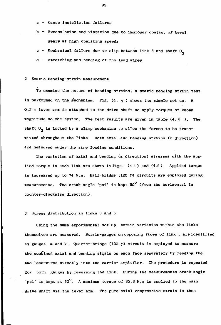
95
a - Gauge i n s t a l l a t i o n f a i l u r e s
b - E x c e s s n o i s e and v i b r a t i o n due to improper contact of b e v e l
gears at high o p e r a t i n g speeds
c - Mechanical f a i l u r e due to s l i p between l i n k 6 and s h a f t 0
d - s t r e t c h i n g and bending of the l e a d w i r e s
2 S t a t i c B e n d i n g - s t r a i n measurement
To examine the nature of bending s t r a i n s , a s t a t i c bending s t r a i n t e s t
i s performed on the mechanism. F i g . ( 4 . 3 ) shows the simple s e t up. A
0.3 m l e v e r arm i s a t t a c h e d to the d r i v e s h a f t t o apply torques of known
magnitude to the system. The t e s t r e s u l t s a r e given i n t a b l e (4.3 ) . The
s h a f t Og i s locked by a clamp mechanism to a l l o w the f o r c e s to be t r a n s
mitted throughout the l i n k s . Both a x i a l and bending s t r a i n s ( z d i r e c t i o n )
a r e measured under the same l o a d i n g c o n d i t i o n s .
The v a r i a t i o n of a x i a l and bending (z d i r e c t i o n ) s t r e s s e s w i t h the app
l i e d torque i n each l i n k a r e shown i n f f i g s . (4.4) and (4.5). A p p l i e d torque
i s i n c r e a s e d up to 74 N.m. Half - b r i d g e (120 0) c i r c u i t s a r e employed during
measurements. The crank angle ' p s i ' i s kept 90° (from the h o r i z o n t a l i n
c o u n t e r - c l o c k w i s e d i r e c t i o n ) .
3 S t r e s s d i s t r i b u t i o n i n l i n k s 3 and 5
Using the same experimental set-up, s t r a i n v a r i a t i o n w i t h i n the l i n k s
themselves a r e measured. Strain-gauges on opposing f a c e s of l i n k 5 a r e i d e n t i f i e d
as gauges m and k. Quarter-bridge (120 p) c i r c u i t i s employed to measure
the combined a x i a l and bending s t r a i n on each f a c e s e p a r a t e l y by feeding the
two l e a d - w i r e s d i r e c t l y i n t o the c a r r i e r a m p l i f i e r . The procedure i s repeated
f o r both gauges by r e v e r s i n g the l i n k . During the measurements crank angle
' p s i ' i s kept a t 90°. A maximum torque of 35.3 N.m i s a p p l i e d to the main
d r i v e s h a f t v i a the lever-arm. The pure a x i a l compressive s t r a i n i s then

96
65
CD
CO
bO
CQ co CD
CO i
CD
CO CD
CO CO Co CD
CO
CO
D)
CD
CO
CO
CO
CNI
CD
CD
CD
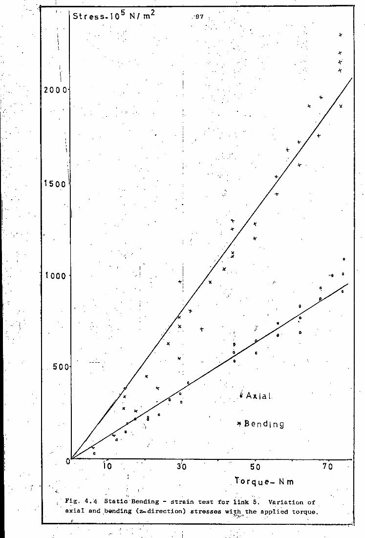
S t r e s s . 1 0 ° N/ m
2 0 0 0
50
T o r q u e - N m
F i g . 4.4 S t a t i c Bending - s t r a i n t e s t f o r l i n k 5. V a r i a t i o n of a x i a l and bending ( z - d i r e c t i o n ) s t r e s s e s w i t h the a p p l i e d torque
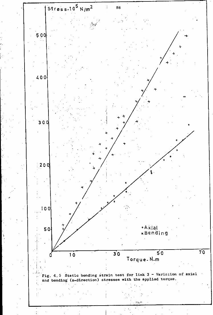
S t r e s s . 1 0 5 N / m 2 98
f
5oq
4 0 0
i
20
100
A x i a l 5 0 B e n d i n g
70 5 0 3 0 10 T o r q u e - Nl-m
• F i g . 4.5 S t a t i c bending s t r a i n t e s t f o r l i n k 3 - V a r i a t i o n of a x i a l and bending ( z - d i r e c t i o n ) s t r e s s e s w i t h the a p p l i e d torque.
99
measured by u s i n g a h a l f - b r i d g e c i r c u i t . S t r a i n gauges on opposing f a c e s of
l i n k 3 a r e i d e n t i f i e d as gauges c and d, and the above procedure i s
s i m i l a r l y a p p l i e d to determine the s t r a i n v a r i a t i o n . R e s u l t s a r e shown
i n F i g u r e s (4.6) and ( 4 . 7 ) .
4. T e n s i l e T e s t
Separate t e n s i l e t e s t s a r e performed on l i n k s 3 and 5. A "Servomex
C o n t r o l s L t d . , tensometer, m e t r i c type-E" i s used i n combination w i t h a
"Peekel 4-channel 4 UD" e x t e n s i o n - box and a "Peekel type 581 DNH" U n i v e r s a l
c a r r i e r - a m p l i f i e r . The t e s t machine i s provided w i t h a u n i t which automat
i c a l l y draws a t e n s i l e t e s t diagram r e p r e s e n t i n g the r e l a t i o n between the
load and the e x t e n s i o n . Two s t r a i n gagues a r e f i x e d on opposing f a c e s of
the l i n k s , connected to the extension box. A h a l f - b r i d g e 120 Q c i r c u i t i s
used to measure the t e n s i l e s t r a i n . A 2500 N c a p a c i t y l o a d c e l l i s employed.
Motor speed was 600 r.p.m.and the cross-head speed tfas 9 mm/inin. A p a i r of
s p e c i a l l y manufactured chucks a r e used f o r each l i n k to g r i p them between
the moving c r o s s head and the base. The chucks were> f i t t e d w i t h heat t r e a t e d
s t e e l p i n s , having diameters as c l o s e as p r a c t i c a l to the i n n e r end bore
diameters of the l i n k s . The chucks were designed to ensure a c e n t r a l a p p l i c
a t i o n of the load. The d i r e c t i o n of the paper movement \ws the_same.as t h a t
of the crosshead. The event marker s w i t c h i s used from time t o time to
record the a c t u a l a p p l i e d load a t c e r t a i n s t r a i n v a l u e s r e g i s t e r e d on the
c a r r i e r a m p l i f i e r . The moduli of e l a s t i c i t y and y i e l d p o i n t s t r e n g t h s a r e
determined from the experimental data shown i n F i g . 4.8 f o r c r o s s - s e c t i o n s
BB and AA of the l i n k s 3 and 5 r e s p e c t i v e l y .

100
s t r U f
ga iJc je - m •A
a x i a l ' v b f e h
i LI N.K-5 7 0 0
5 0 0 i
i CL
200 a.
30 10 n To rq ue. N_m
30 0
5 0 0 i
i 70 0
gauge-m 1 0 0 0 1
s4 i I I
12 00
c a s e.T c a s e»2 (I j n k. r e v e r s e td ) •
F i g . .4.6;
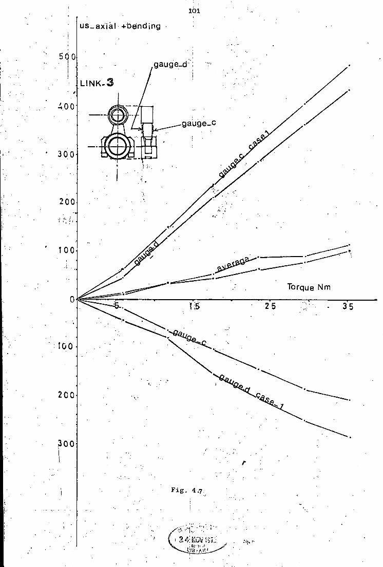
101
us_ axial +be'nding
i
500 gauge_d
L I N K-3
400
gauge_c
300
00
100
Torque Nm 0 I S 25 35
100
200
300
F i g . 4.7 i
24:K0Vi
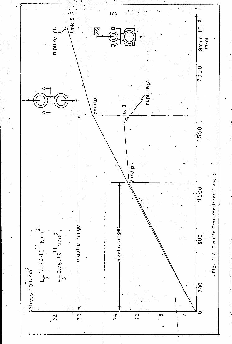
102 CO
03 CO
CD CO
I—« 0)
L O
(0 CO (A
V) 0
CNJ CD
in CD
CO (/) 00 CO TO CD CU 0)
CO l bo CN
II I I L O CO LU O CO CO 0)
CO CD
CM

103
4.5 Dynamic S t r a i n Measurement Results
Since two a c t i v e gauges are connected i n a h a l f - b r i d g e c i r c u i t f o r
each set of r e s u l t s , the reading from the bridge i s twice t h a t which would
be expected i f only one a c t i v e gauge were used. The r e s u l t s are t h e r e f o r e
d i v i d e d by two t o ob t a i n the r e a l s t r a i n and s t r e s s values shown i n Table (4.2)
The v a r i a t i o n of the peak t o peak stresses (both a x i a l and bending) w i t h
the crank speed f o r l i n k s 3 and 5 are shown i n Figures 4..9 t o 4. 13
Experimental sample s t r a i n p a t t e r n s obtained, are shown i n F i g . 4.14, a - f f o r
various crank speeds. Experimental v a r i a t i o n of the c y c l i c a x i a l stresses
i n both l i n k s w i t h the crank angle .. are presented i n Figures 4.1'5and 4.16.
4.6 Speed F l u c t u a t i o n
Crank arm speed i s assumed t o remain constant d u r i n g a measurement.
However the f o l l o w i n g s i m p l i f i e d t h e o r e t i c a l c a l c u l a t i o n based on t o t a l
k i n e t i c energy of the system i s made t o p r e d i c t an e s t i m a t i o n ;
Let
= Moment of i n e r t i a o f the main d r i v e s h a f t w i t h the flywhe e l
I = Moment o f i n e r t i a o f s h a f t 0 o
I g = Moment of i n e r t i a o f sha f t 0^
From F i g . 3.6 (Torque diagram, f o r the crank speed = 2500 r.p.m.), Let o
be the angular v e l o c i t y of the crank arm at the crank angle . ijf = 50 . Also l e t Q. and 0- be the angular v e l o c i t i e s of s h a f t s 0 and 0„ at the
2 2 2
same crank angle. Then 2 ( T o t a l K i n e t i c energy) + *2^4 + I3^6 = c o n s t a n t
or
2 (K.E) 2 -„ . " • i - — — » - ( 4 : i ) 02
104
The v a r i a t i o n o f are shown i n Table 4.1 f o r various crank angles, 0°-^360°
by 10° i n t e r v a l s a t an average crank speed o f 2500 r.p.m. = 261.798 rad/s.
From t a b l e 4.1, c o e f f i c i e n t of speed f l u c t u a t i o n i s ;
^nax " °min 2 6 7 - 4 3 ~ 2 5 3 - 9 5 C = = 0.0515
S 0 261.798 av
speed f l u c t u a t i o n i s also measured experimentally by using the u.v recorder
and the speed pick-up u n i t i n combination as explained i n 4.1. The
experimental average value o f c o e f f i c i e n t o f speed f l u c t u a t i o n obtained
was 0.082

1.05
Table 4.1
crank angle p s i (degrees) °2 rad/s
crank angle p s i (degrees)
o 2
rad/s
0 263.95 190 267.43
10 266.68 200 267.41
20 267.43 210 267.19
30 266.26 220 266.88
40 263.82 230 266.56
50 260.93 240 266.25
60 258.29 250 265.91
70 256.39 260 265.39
80 255.58 270 264.53
90 255.99 280 263.10
100 257.50 290 260.96
110 259.64 300 258.26
120 261.81 310 255.61
130 263.52 320 253.95
140 264.63 330 254.12
150 265.35 340 256.35
160 265.97 350 260.05
170 266.60 360 263.95
180 267.14

5 2 s t r e s s . 10 N / m
24 0
2 0 0
150
100
50
106
1. Theoretical
2. Experimental
-r-S> 1000 1 500 2000
crank "speed r;'p:m; 2 5 0 0
F i g . 4.9 T h e o r e t i c a l and experimental v a r i a t i o n of a x i a l s t r e s s range (peak t o . peak s t r e s s ) i n l i n k 5 w i t h the crank -speed.

1 0 " N/m 107
3oa
25a
200
I
150
no
•000 1500 " ' ' 2000' ' ' ' 2500 crank speed r.p.m
F i g . 4.1Q Experimental v a r i a t i o n of bending (;&-direction) peak t o peak stress ( s t r e s s range) i n l i n k 3 w i t h the crank speed.
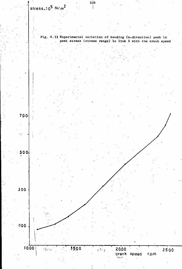
108 s t r e s s . 1 0 5 N / rn 2 I
F i g . 4.11 Experimental v a r i a t i o n of bending ( z - d i r e c t i o n ) peak t o peak st r e s s ( s t r e s s range) i n l i n k 5 w i t h the crank speed
i
700
500
300
M'OO
I 1000 ,V5;Q0 2 0.00 25 00 crank speed r P m
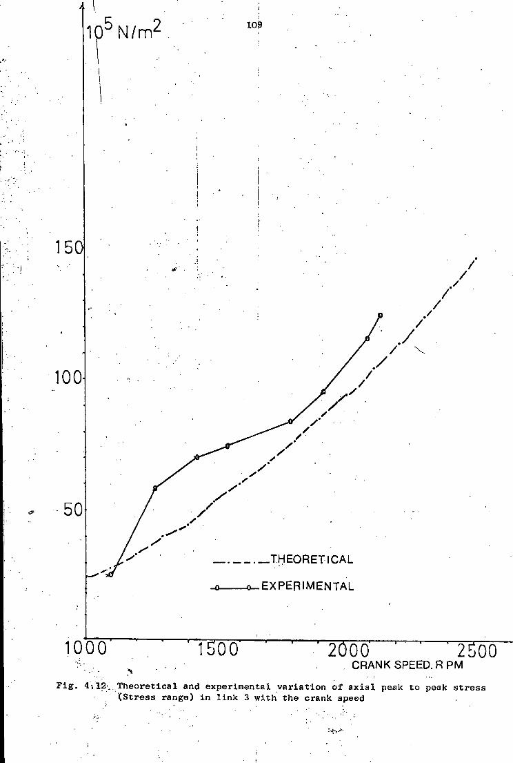
1 0 5 N / m 2 109
T H E O R E T I C A L
-o_ E X P E R I M E N T A L
1000 1500 2000 " r~250Q CRANK SPEED. R P M
F i g . 4i12. T h e o r e t i c a l and experimental v a r i a t i o n of a x i a l peak t o peak st r e s s (Stress range) i n l i n k 3 w i t h the crank speed
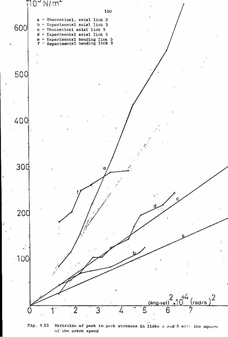
iCTN/m 110
T h e o r e t i c a l , a x i a l l i n k 3 a Experimental a x i a l l i n k 3 b 600 I h c o r e t i c a l a x i a l l i n k 5 Experimental a x i a l l i n k 5 Experimental bending l i n k 5
f - Experimental bending l i n k 3
500
400
30G
f
/ 20C
100
2 ..+4 (ang-vel) *1 0 ( r a d / s )
7 0
F i g . 4.13, V a r i a t i o n of peak t o pt\nk stresses i n l i n k s .1 dud'5 w i n tho sqiuiro of the crank speed

i n ;
F i g . 4.14 Experimental s t r a i n p atterns
:a Record 80. Link 5. Experimental bending ( z _ d i r e c t i o n ) s t r a i n r j a t t e r n . Crank speed = 1573 r.p.m. & Bridge ( 1 2 0 o ) 2 c i r c u i t . Peak t o peak s t r a i n = IS7.4 us, Peak t o peak st r e s s = 205 x 10 5 N/m
b Reco'rd 99. Link 5. Experimental bending ( z - d i r e c t i o n ) s t r a i n p a t t e r n . Crank speed = 2023 r.p.m. £ Bridge (120O) c i r c u i t . Peak t o peak s t r a i n = 417.5 u« Peak t o peak st r e s s = 433.8 x 10& N/m

112
AUS
wmvm 5 H r- l-cycle
c Record 131 Link 5 Experimental a x i a l s t r a i n p a t t e r n . Crank speed = 2130 ' \ Bridge (.1200) c i r c u i t . Peak t o peak s t r a i n a 203.9 |j,s. Peak t o peak
str e s s = 211.8 x 10⁵. N/m
AUS
d Record 16. Link 5. Experimental a x i a l s t r a i n p a t t e r n . Crank speed = 1634 r.p £ Bridge (120n) c i r c u i t . Peak t o peak s t r a i n = 86.7 p,s, Peak t o peak s t r e s s = 90 x 10 5 N/m
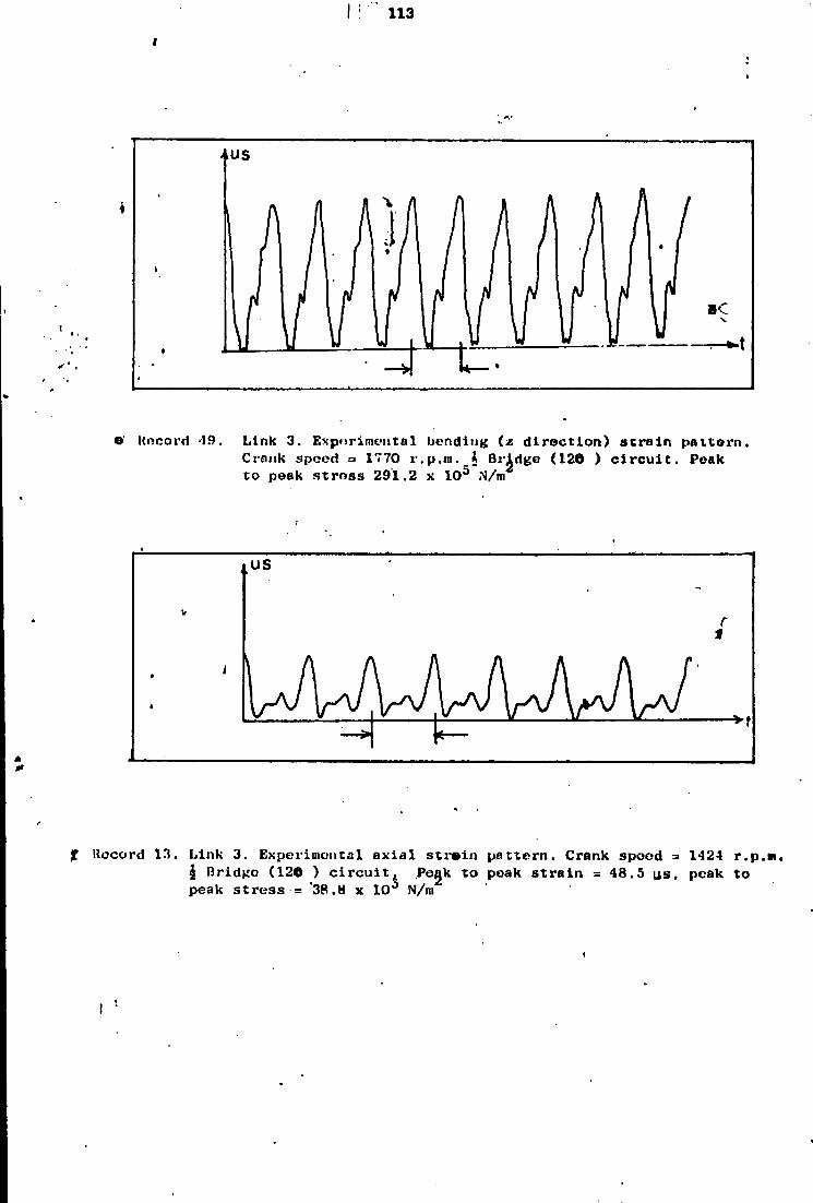
I : " 113
>,US
j « m
9' Uncord '19 Link 3. Exporime-tital bending (z d i r e c t i o n ) s t r a i n pat t o r n . Crank speed - 1770 r . p . j n . f t Bridge (126 ) c i r c u i t . Peak t o peak s t r e s s 291.2 x 10 J N/m
US
Record 13. Link 3. Experimental a x i a l s t r a i n p a t t e r n . Crank spoed - 1424 r.p | Bridge (120 ) c i r c u i t j, Pegk t o peak s t r a i n = 48.5 us, peak t o peak s t r e s s = *38.8 x 10° N/m
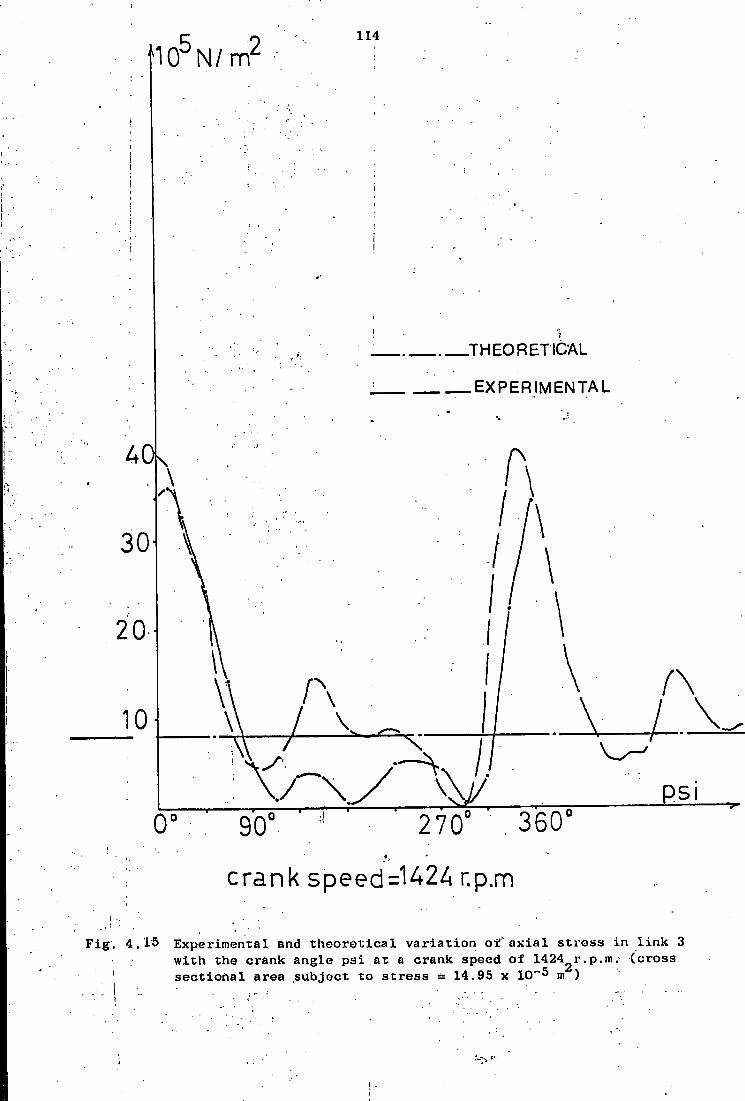
f 1 0 5 N / m 2
114
Ad
30
20
10
K
0'
T H E O R E T I C A L
E X P E R I M E N T A L
90
• A
. A
270 .360
crank speed=142A r.p.m
F i g . 4.15 Experimental and t h e o r e t i c a l v a r i a t i o n o f ' a x i a l s t r e s s i n l i n k 3 w i t h the crank angle p s i a t a crank speed of 14242r.p.m.- (cross
' s e c t i o n a l area subject t o st r e s s = 14.95 x 10~5 m )
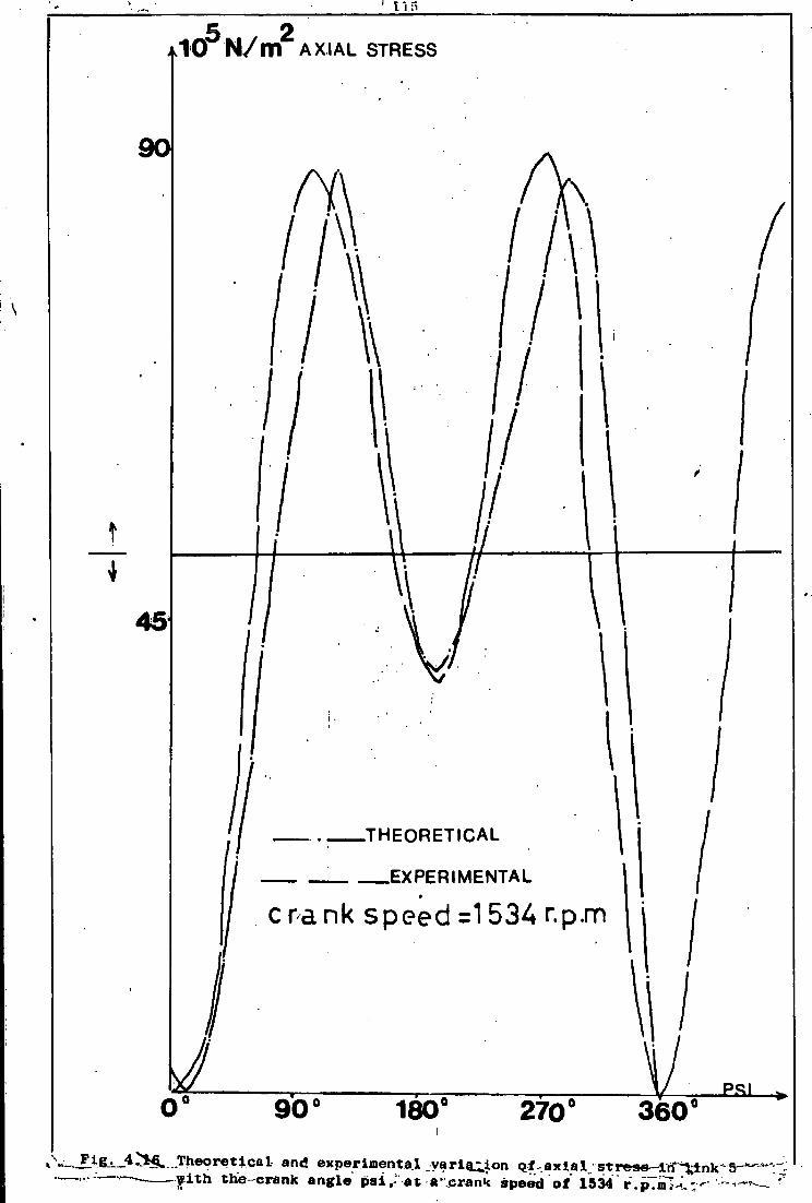
JktO N / m A X I A L S T R E S S
II' \ \ I W I /
t
. • l i
'jf . T H E O R E T I C A L ^ I
11 '. EXPERIMENTAL /
J c r a n k speed =1534 r.p.m | j
u M 0°
ESI 90° 270° 180° 360° » s ,»:-J^*i- 4^*§*..Theoretical and experimental v a r i a t i o n q f . a x l a l j s t r e s e - l n ^ i n k - 5 ^ J ^
•• . — - v i t h the crank angle psi,- at a .crank speed of* 1534r. pTinlU.-.' ~

116
CM
...m/N o 0 l * 6 S
iH r- CO cn CO CM i-H oo m co QSUBJC s s 3 J 3 g
p^ CO co CM
oo CM
CO CM
m O CM
cn i n l-H
co m
p-i CO PH I - I CM
| 250.
oo CO
CM co CTJ CM M< CO co 00 I-H i n
; s n O S U B J U T P J I S
O CO
m oo O CO
i n co
cn CM
l> m CM
CO m m i n m
,PH
l-H |H
cn ' O
CO
313.
248.
•UJUI S S U B J pjooay m o" CO
co CM
i-H CO
in CO
I n
cn CM
co CM
CO co m | 15.5
42.5
m en CM CO
m p-i
• i i iui u o f a o a i i a p ^ X B O S T [ n j
i 151.5
= o i n •H
:
151.5
s o i n i-H
=
153.3
=
154.5
• m m - T B U S X S uoxaeiqfXBo in 6 m O m
i f l
o" m
r = O m r
46.0
= - 51.5
• sn U O t a B J t q T T B O
o o i .r 1000
O O iH
OOOT
O O rH
= o o CO
r O o P-I
•sn l -oa p a i i T q s aSuBJ
o, o: co 10
00
3000
3000
O o CO 30
00
O o co 30
00
1000
s
3000
1000
• sn aSuej: T B T I T U T
o o CO
r r
3000 o
O CO
= 3000 O
O CO -
1000
-o o co
u o T f i B j n 3 T j u o » Two
tive
arms-:..
. . . - , _
aSpxjg - o
p a j n s B a i i i u i B J a s j o adXj, Ax
ial
Bend
ing
Axia
l
;
Bend
ing
r
1 —
Axia
l
Bend
ing
' r =
Axia
l
' UIUI S J 8 A O O aToXo x
m co r r t>
• m CD m
iH : r 14
.5
m i-H =
• ttioi = o a s T
aui"[ jam pa l i i ' i j j 00 i - i i - i
cn iH l-H
pH CM i-l
CO I - I pH
CO m CO
: m CO
CD m CO
r • =
•wd'a j a a a m o i i O B j ,
1080
= : r 1440 : = r r
• w r l - j 'T B U S T S dn - i j o T.d paads j a p j o o o j " A n 10
89
r = 1037
1089
1424
= 1416
1424
1473
1424 j
• s / m i i r paads ja d e d T. BUT. WON
I - I rH r-l
: = r -CO CO CO
1 111
co co co
r r
3 T . B O S joaon O CM CM.
: = r • r t o o CM
= r : =
j a q u i n u i [ U T ' j m = CO = r • r m = s - CO CO CO
. i s q u i n u pjoooy i I CM
I CO
1 1 m co i
t - oo cn 1 O p-i
1 rH PH
CM pH
1 CO rH

,117
. U,/N „0I* o S
aiiuBJ ssa.i3[j 70.6
92.8
' 1
o en r-l CM i H
r 100.8
1
-i
141.3
1
48.7
j
99.2
1 38.6
{
- f H CM I H
CM •
rH
rH
•sn aSuBJ uxeaas
67.9
89.3
86.7
116.5 = r> a> CO
CO 1-1
46.9
95.5
37.2
s
116.5
j 135.9
• uiu! aSue.i paooay i > CM
en 26.81
CM i H
r O | H rH 14
.5
29.5
11.5
CM I H rH
• m m uoxq.oaT.iap i 15
4-
5i
•u iu i" T B U S X S uoxae.lqxT.eo
i n
i H m
• sn u o x i B . 1 q x T . B 3
8 rH
• s n *oi p&ljxqs aSuBJ 30
00
r 1000
3000
= = • = 1000
-• = = 3000
=
• sn aSusj T . B X I T U X
8 CO
uoxiBjrnSxjuoo aSpxjQ Ac
tive
arms.'
pa.inseaui U I B J I S j o ad^x Ax
ial
= = : = = : - =
' UlUi S J 3 A O 0 3TOiCo 7.
m f H
<*< i - i
CO P-I 12
.5
CM i - l = 10
.5
i> rH 12
.5 m
CO s CM H
rH f H
• u i w = oas r aui [ a a u i T i u i d j
m CO
r r CO m CO
r m CO
r CD m CO
s 00 rH rH
. O CM r H
m CO
CD m CO
•ui'd^a .xaiauioqoBj,
1440
1560
- 1800
= 1680
1980
1320
1680
1080
=
1800
1980
• i u - d - j " T E U S T S
d n - j j o x d paads .iapjooaj " A n 14
16
1517
1
1634
1709
1780
1770
2023
1256
1709
1089
1108
1770
1942
• s / i m u • paads jaded T. BUT WON
CO CO CO
: r = = = r = 111 CO
CO CO
=
aiBos aoaow 8 CM
O a> i H
= o co pH
: m oo i H
lO c~ | H
O i H CM
m oo rH
O CM CM
• o oo f H
i n i > i H
aaqmnu ^ u x q i n
j a q u i n u pjoosy i
i H
i m i H
co rH
l > f H
1 CO i H
i
i H
1 o CM
1 rH CM
CM CM
1 CO CM
1
CM
1 m CM
1 CO CM

118
. ?
l u / N g 0 i x
G B U B J s s a j a s 156.
4
186.
6
1 18
1.5
j
77.6
89.3
= m T-t T-i 1
24
.24
163.
4
38.8
j
16.8
58.2
73.7
•sn aS i iEJ 150.
5
179.
6
174.
7 e'en 11
6.6
11
6.5
143.
7
155.
3
157.
3
i-i CM 72
.8
92.2
• UIITJ O 3 U B J pjooa>i in in f-i
in •
oo H
co i-i O T-t
in I-I i-i CD
CO
CO •
T-i
co r-i 16
.2
m r-i
in CO
m •
m en
•uim u o x i o a x j a p £>XBOS u n j 15
4.5
• mm • T BU3XS uoxaB.iqxx&0
IO t-t m = = = = - : - =
=
• sn U O T l B J q i l B O
OOT
1000
o o r-i 10
00 o
o r4
r = = - =
ooot
=
•sn "oa p a i i x q s S S U B J 30
00
r = 10
00
3000
OOOT
r
3000
r
• sn aSuea XBT1T U I
O O CO 30
00
O o CO
r
3000
o O CO =
3000
O
3000
U O X I B J I T S X I U O O a3pxjg
CO > in 0 -H e. 1 | J fi ft O CO
:
= = = • = = -
pajnseaui U X B - I I S j o adA"j,
Ax
ial
• = = = - = - r -
' UIUI B J O A O O Q T O X O X 1
0.5
r H r-i i-i
=
T-i T-t
O f-l T-t t-t
. o CM 1
9.5
17.5
in f-i
• IUIU = oas x CD m CO
in CO
t £ T-t T-t
co m CO
m CO
CD m CO
m CO - • = -
=
•m-d'a aajaiuoiiOBx
2040
2160
=
1560
1800
1920
2040
2160
2040
1080
1320
1440
•ui'd'.i • T B U 3 T S dn-jpxd paads
j o p j o o a a *An 2034
2023
1931
1517
1785
1942
2136
2124
1942
1062
1089
1214
1416
• s/miir paads j a d e d XEUXUION
CO CO CO
t r
111
CO CO CO
r = • =
r r
ox BOS aoao(\| o r-r-i
m CD - O en
I-I
O CO I-I
m t> i-i o [> r-i
m CO r-i
o 1-1
o CM CM
8 o f-l CM
O O CM
.raquinu ^uxq m '- CO : j = m CO r - =
.laqiunu pjoooji 1 r» CM
i oo CM
i en CM
i o CO
1 T-t CO
i CM CO
1 CO CO CO
i m CO
1 CD CO
1 t-CO
CO CO
1 en CO.

119
• Z
U 1 / N g0I>=
69
.9
j
77
.6
|
TOT 1
88
.9
!
20
9.7
23
6.9
co •
CM
1 2
50
.8
28
7.3
29
1.2
[
oo •
l> CM 2
91
.2
I
i> a.
o co
•sn a3injj U T B j a s 87
.4
t> cn 1
26
.2
23
6.2
26
2.1
29
6.1
30
5.8
31
3.5
35
9.2
to CO 3
39
.8
co CO
•
• uiiu ctSutix p jooajj cn O CO CO t>
t> CM
in 8
in fH CO
PJ CM CO
c-co
• t-co
i m CO
ift •
co CM
•mm uocqoox.iap 1
54
.5
• urm * TBu3xs L!OT: .IBJC[ I; [63
IH iH lO
• sn
uoTiB-iqixeo o O iH 10
00
=
o O iH
I r - s - r
• sn ' o t pa i j . xqs aSuBJ 30
00
=
1000
3000
- - = =
r
OQ
OT
• sn a3uB.i X B T 1 T U T
o o CO 30
00
=
o o CO r . r i s -
uoxiBJcnSijuoo aSp.Tjg
\ T
wo
Acti
ve
arm
s
paanseam U T B . H S j o adiCj, A
xia
l
=
Ben
din
g
= c - i
= = =
' IUUI S J 3 A O D aTOA"o 1 1
3.5
CM i-l 11
.5
O CM 1
5.5
13
.5
12
.5
CM i-l r CO f-1
CM
m •
en |H
• uiiu = oas i aux"! jauica U O J J
CM m CO
to in CO
m CO
: =
O m CO
m CO
co m CO
CO m CO
>* m CO
CM in CO
^ * in CO
CO m CO
•ui"d".x jcaaauioqoej, O to m O O oo
O co cn O 00' o
6 CM CO
O "CP M<
O co in O oo CO
O O 00
O CO en
O co m O O 00
o 00 o
• in • d • .1 • T BUS T s dn->pxd paads
.iap.ioc>G.i - An co in
O oo o i> CO
CM CO o
en CM
m m CO
CO m
en O i>
m CO t>
O o t> m CM co
O o t> in cn O
• s/iiiur paads j a d e d TEUTUION
CO CO CO
ox BOS aoiow O en i-t .
O co m o o CM CM
O CM
8 CM
O en m CO
• O 00
m t> b cn o co
O CM CM
joquinu JJUTT CO
jaqiunu pjooay • i O iH
<*
1 CM
1 CO
1 in i co t> 1
co i
cn i
O in
i iH m
1 CM in
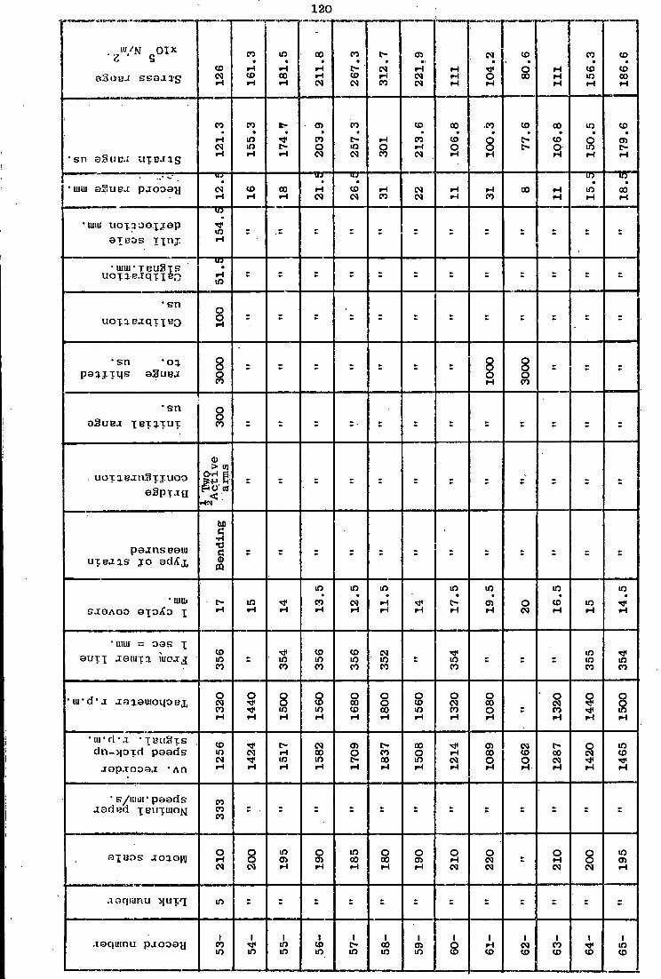
120
Z 9
8 3 U B . £ s s o a a s co CM r-l 1
61
.3
1 1
81
.5
j
21
1.8
'
j
26
7.3
31
2.7
22
1.9
111
10
4.2
! i
80
.6
| —
J
111
15
6.3
j
| 1
86
.6
• sn oSuc.j u x c n g 12
1.3
15
5.3
17
4.7
20
3.9
25
7.3
rH O CO
1 2
13
.6
10
6.8
i 1
00
.3
77
.6
10
6.8
15
0.5
17
9.6
• uiui QSUBS paooay .
CM iH
co |H
co I - I
• |H CM
. co CM
fH co
CM CM
iH iH
fH CO
co •H iH
m •
i n rH
m •
CO iH
*UnU U O T 3 0Q.XJSP
S T U D S i x n j 154.
5
" UIIU ' T B l l 3 x S uoTiB.lqxxfeo
i n •
m - r t r s : s r
= : : -
• s n
uoxaBjqxxtso o o r-4
• s n " o j p a i i x q s a S u s j 30
00
= = r - s ; r
1000
3000
- t -
• s n
aSuea "[Bxq.TuT o o CO
uoxaBjn3xj.uco a S p x j f j
h T
wo
Acti
ve
' ar
ms
p a j n s B a u i
U X B J I S j o ad/Cx, Ben
din
g
' UIIU S J S A O O STOiCo x
t-fH
i n fH i-l 1
3.5
12
.5
11
.5
iH 17
.5
19
.5
o CM 1
6.5
i n fH 1
4.5
• unit = oas x auxx l a i i i f i iuo j j co
m CO =
m CO
co m CO
CO m CO
CM i n CO
s m CO
: -m i n CO
m CO
• u i " d " j jaaswoqoBx
1320
1440
1500
1560
1680
1800
1560
1320
1080
r
1320
1440
1500
• u r d - . i " x B i i a x s
dn->pxd p a a d s
.iop.Tooa.1 'An
co i n CM
CM r-I-I m
CM CO m
cn O o r> CO oo
oo O m |H CM
a> CO O
CM co
o
o oo CM
O CM
m co
• s/miii' p a a d s j a d e d xewxuiON
CO CO CO
- - = - = = = = -
a [ B O S J O I O I \ I o I-l CM
8 CM
m Oi I-I
o CD iH
m co fH
o oo |H
o cn |H
o fH CM
o CM CM
r o fH CM
o o CM
m 0) iH
joqiiinu >iuxq i n
.xaqumu p j o o a y i
CO m m
i m m
1 co m m
1 CO i n i n
1 O CD
1 PH co
I CM co
1 CO CO
41
CO i n co

121
"</N 01 x Z S
O3UB.I s s o a a g 22
1.9
26
7.3
31
2.7
!
• •
t>-fH 1
95
.7
j
cn CM csi 2
48
.5
|
^ < CD CM 2
79
.6
|
75
.6
|
102.
5
14
4.5
• sn o3uea uxeaas 21
3.6
25
7.3
rH
21
8.4
24
4.6
j
28
6.4
310.
7 j
o CO CO
•
j 3
49
.5 00
•> CSI o 9
8.7
13
9.1
• mi:; aSuua p jooay CM CM
m •
CD CM
iH CO
m •
CM <M
CM •
m CSl
m •
en CM
CM CO CO
CD CO 2
2.5
30
.5
co
• HIM uoT0.ooT.iap o i B O S T t n j 1
54
.5
• UUU " T BuS-TS uoxaBiqTXfeD
m •
fH m
• sn l iOTiBJqiXBO
O O t-i
•sn 'o% poq.iT.us aSuBJ
3000
s - = ; : - -
1000
-
• s n aSUBJ 1 BT J.TUT o
UOTlBjnSTIUOO a3pxj:g h
Tw
o A
cti
ve
arm
s
- - = = = = = = = = = -
poanseaui uteaas T O adXx B
end
ing
- UIUI
sjaAoo oroXo i iH CM iH
= O CM rH
in rH fH
CO fH 1
2.5
csi rH
o csi 1
7.5
m iH
• IUUI = oas j 3UTT aauiTa U I O J J m
CO s
CD m CO
cn m CO
co in CO • =
r =
m CO
CD m CO = - m
CO
' u r d ' a jaaaiuoiioex o CD
m
O X CD
O 8
O CO
o
O CM CO
O •* ^ O s
o CD
m
O CO CO
o o 00
o oo O
o CM CO
o
d n - i | O T d paads o iH m
o r>
o CO
r> c-o
CO m CM
<d<
CD CM m
CO
co cn cn CD
o 00 t> oo co O
rH CM CM
CO fH
• s/uiur poads . isded IBWTIUOK
CO CO CO
3TBOK .I010HI O crs fH
m oo wi
o CO H
o CM CSl
O fH est
O O CM
m cn rH
O cn rH
m 00 rH
o oo rH
O CM CSI
O rH CM
o o CM
joqiunu J I U T T m = =
CO : = = = =
m = =
•ioqiunu pjtooaji CD CD CD
1 co CD
1 cn CD
o o I
fH r>
1 CM r>
1 CO r>
in r-i co
t -
1 t> t -
1 oo

122
sSuc. i ssoaqg 16
4:8
m O 2
06
; 7 iH
CM m CM
r> CM iH CO 3
68
.1
80
.7
22
1.9
|
oo o CO
o in 60
.5
*• o CO 11
1
•sn a a u B J U T B . H S
CD
CO m t-i 1
97
.4
cn cn iH 2
42
.7
fH O CO 3
54
.3
CO
r> r>
21
3.6
CD - CO
m • oo 5
8.2
77
.7 8*901
• IUUI S S U E . I p jooay 01 t~t CO 2
0.5
m CM
rH CO 3
6.5
co m
• CM CM 3
7.5
in CD oo rH fH
•uni i uoxaoaxjap P I BOS T in . !
IB
m .
• u m r T E U S T S u o x i B i q x t BQ rH
m
• sn U O T . a B j q T . T G 3
O o t-t
• sn ' o j p o i i x u s 8 3 U B J
1000
• sn a S ' J B J T B T 1 T U T
o o CO
uoxiB-rnSxiuoo a S p x j g
Vco O H f i
= = - = = = = = r
pejnsBaui U T B I I S j o acMx B
endin
g
= : . : r
= - s
Ax
ial
s = -
' UIUI S J 8 A O O aToAo x 1
4.5
13
.5
CO t-i
CM fH 1
1.5
fH rH
o CM 1
3.5
11
.5
o CM
t-fH
m fH
CO fH
• mm = oas x
auxx aoiuxa mnaj CD m CO
m CO
: - -CD in CO
m CO
O • in CO
m CO
CD in CO
CD «3< CO
m CO
• u i ' d ' j jaiauioqoBx
1500
1560
r
1680
1800
1
1980
1080
1560
1980
1080
1320
1440
1560
• w d " . i •TBiiSxs d n - > [ o x d paads
aopjooaj; "An
CO c-
CO
m ^ < CO co
O r> r> r> «* CO
rH CO cn
CO CD O
CO r~ m
co CM 00
CM co o
CO m CM
CO CO
CO CO
• s/mw paads . z a d B d XBUXUIOM
CO CO CO , =
r : = = =
: s - =
a X « o s J O I O I V m cn t-i .
o cn t-\ =
in CO fH
O oo fH
m r> fH
o CM CM
o cn H
in o fH
O CM CM
O rH CM
o o CM
o en rH
.laquinu : > i u x q m =
r = = = - £ - r
= = =
jaqmnu pjooay cn o o 00
fH oo
CM 00
CO 00
i co
1 in CO
CD 00 00
00 00
cn CO
o en
1 fH cn

123
"'U/N „ 0 i x Z S O 3 U G J s s o . u g
iH CM rH 13
1.1
70.5
161.
3
211.
8 |
1 31
2.7
| 37
3.2
433.
8 { >
| 90
.8
1 i
i 186
.6
! >
<
j 27
7.4
j
363.
1
418.
7
• B l l a S u E J UTBJaS
116.
5
126.
2
67.9
155.
3
203.
9
rH O CO 35
9.2
41
7.5
87.4
!
179.
6 1
o CO CM 34
9.5
CO
o
• I U I U p j o o a y CM rH
CO fH
CO iH
•H CM
rH CO
t> co
CO 05 18.5
27.5
1
co CO 41
.5
• U I U I uoxaoaxiap 3 T B O S \\x\j.
j 15
4.5 i
• uim" T B U S T S U O X I B . I q f T B O
51.5
• sn U O X. 1 B J CJ T. •£ B Q
o
a
• sn ' O l
p a a j x q s a3uBJ
i
3000
• sn aSUBJ T E X I T U X
o o CO = = = -
u o x i B j n S x T U G O
aSpxag
<D X O
- = = = s
i
r r =
p a a n s B a u r
U T B J J S 10 adAx
Ax
ia
l
:
Ben
din
g
-= = =
-= '
r
• mm S . I 9 A O O 3 X O A " 0 i
12.5
CSI fH O
CSI 15.5
fH 12.5
11.5
10.5
O CM
m iH 13
.5
CM rH 11
.5 |
' \mu = o a s i O U X T . x a u i x a i i i o j c j
CO
• m * d ' j jaaamoqoBx
1680
1800
1080
l
1440
1560
1800
1980
2040
j
1080
1440
1560
J 18
00
1920
• i u ' d - j ' • X B U S X S
d n - M . o x d paads j a p . i o o a j " A n 16
99
1770
1062
1370
1517
1699
1847
2023
1062
1416
j 17
70
= 1847
• s / u i u r paads j a d B d [ B U X U I O N
CO CO CO
ax B O S a ojoiv lO CO H
o co fH
O CM CM
o o CM
o o fH
O CO rH
m C -|H
o o rH
O CM CM
O O CM
O 05 rH
o co rH
i n r> rH
. r a q u i n u >IUXT m = - = = -
a a q i u n u p a o o a y . CM
a> 1
CO 05
1 1 lO OJ
CD 0)
l > 0)
CO 05
o> 05
1 o o
rH O
1 CM O
CO o
i
O

124
. U l / N „ 0 i x Z 9
O H U B J s s a j ^ g 48
4.2
55
4.8
56
4.9
48
9.3
|
40
3.4
{
63
5.4
50.4
60
.5
80
.7
111
1 136.1
|
151.
3
176.6
|
' sn aSuBJ u x E J i g
co co «#
CO m 5
43
.7
47
0.9
388.3
611.
6
48
.5
1 58.2
77
.7
1
106.8
rH CO rH 1
45.6
O t-rH
• mm aSutj.i p j o o a n co m m
co m 4
8.5
O CO co
m co CO rH rH 1
3.5
m rH 1
7.5
•unu uoxaoaxjap a T B O S r x n j 1
54.5
= = = - = - r - r =
• IIIIU • T B U S T S 10
•
r-l
m
- = = = : ; t r - • - =
• sn UOXJBjqfXBQ
0 0 rH
r • : : s
• sn - o j p a a j x q s aSuBJ
3000
- = - r =
r = =
• s n aSuBJ xexaxux
O O CO =
r r . =
r =
r . - r
u o x i B j n S x j u o o aSpxj t j
t i T
wo
A
cti
ve
arm
s
= = - s - r = =
pajnseaui U X B J I S j o ad/Cj, B
end
ing
r = = - = A
xia
l
r =
- r : r
' UIIU
S J 8 A O O B T O X O x 10.5
•
m cn O
i-H 10.5
11.5
in cn 1
9.5
16.5
m 1-1
CO rH 11
.5
rH rH 1
0.5
j • Mill = D O S T
auxx joiuxq. m o j j r e m CO
1 : r r r =
: = =
• u r d ' j aaaauioqoBi
2040
2160
= 2040
1980
23
75
1080
1320
1440
1560
1800
1980
2040
•lu-d-.r • T B U 3 X S
d n - > p x d paads j a p j o o a j -An 2
023
22
36
2124
2023
1847
22
36
1089
1287
1416
1634
1847
1
1931
2023
• s/iiiur paads j a d e d [ E U X U I O J J
CO CO CO = • r r t t r r - - =
r
ax B O S J O I O J V 0 c-iH
in CO rH =
O t-rH
m t-t-i O co 1-1
O CM CN
O rH CM
O O CM
O en rH
O co rH m t> rH
O t>
jaquinu J j u x q in = = - • = = = =
r =
jaquinu pjooay
105-
106-
107-
108-
-601 1
10-
111-
112-
113-
114-
115-
116-
117-

125
u i / N n i x
aSuuj ssaa'a-g
c-rH en iH 21
6.8
<M M< CM
CM CO CM 21
1.7
65
5.7
52.1
j
146.
2
CM CM iH
CM r-t r-t
90.8
211.
8 |
186.
6
•sn aSuea U X E J I S
184.
5
20
8.7
CO CO CM 2
23
.3
203.8
r-t CO CO
iH
o m 140.
8 j
117.
5
107.
7
87
.4
20
3.9
179.
6
' uiiu O S I I B J p a o o a y
•H. 21.5
* f CM
CO CM
CM
r-t CM
m •
cn 15.5
m
r-t 12.1
r-t r-t ->
en rH CM 1
8.5
•umi uoxaoaxjap a i B O S T r n j 15
4.5
j = CO i n
m re m iH
r £ £ =
" UIUl • T B U S T S UOTlBJqTIBO •
t-t m = = CM
i n 51.5
- - = £
= -
• sn . uoxaBaqxxBO
OOT
r = - = 1 =
• £ £
•sn ' oa p o a j x q s eSuBJ 30
00
= r
OOOT - 3000
= £
= £
• sn aSus-i X B T 1 T U T
ooe
uoxaB . in3xjuoo aSpxag 4
Tw
o A
ctiv
e ar
ms
= -
pojcnscaiu u x s a a s . 1 0 adA"j, A
xia
l
= =
Ben
ding
-
Ax
ial
= £
Ben
ding
Ax
ial
• urm S J 8 A O O aToXo x o
iH
m m
en en
m •
co o CM
CM
i n
T-t CO
i n •
m CO
CM •
o
• I U U I = o a s x
auxx aauixa u i o a j <* m CO = - t 0 )
r-t r-t
m CO
CO m CO
m m CO
<3< ; i n CO
lO m CO
m CO
CD m CO
• u r d ' j j : a i a m o i . [ O B j ,
2160
2375
2450
2500
1600
2550
1075
1810
= 1600
1355
1600
2050
• u i ' d M "TEuaxs dn->pxd p a a d s
j f > p . i o o a a - A n 2124
2236
2360
r
1785
2499
1068
1775
1847
1639
1370
1 16
43
2094
• K / I U U I * p a a d s . x a d E d X B U X I U O ^ CO
CO CO
r - r
111
CO CO CO
- = £
= £ £
aXBOs Joao|/\| i n co r-t •
O co PH
m m r-t
CO i n rt
O 05 rH
o m iH
o CM CM
O CO r-t
o en r-t
o o CM
o cn iH
o rH
jaqunu M u T r I i n = - r
= s = - £ =
. £ £ £
aaqiunu pjooay
118-
119-
120-
121-
122-
123-
124-
.
125-
126-
127-
128-
129-
130-

126
. G < V N g 0 i x
aSuns ssoang 211.
8
50.4
40
3.5
]
TT
S
co
rH r> m
1 21
1.8
I 1 9
5.8
I >
rH CM rH 16
1.4
376.
6
302.
6
63
5.5
|
722.
9
•sn a B u B J u x B J i g 20
3.9
48
.5
388.3
491.
9
550.
1
20
3.9
92
.2
116.
5 |
155.
3
36
2.5
291.
3
611.
6
695.
8
* uiiL1 a S u e j p a o o a y i H CM
m rH
CM rH 15
.2
r> f H
f H CM
i n • •
cn CM f H
CO r H
CM
rH f H
cn
CO
co
m
rH CM
• u n a u o x a o a T . i a p
a t e o s u n j 154.
5 s
= - = = r
• UiUI" T B U S X S U O t l B J q X T B O 51
.5
= =
• sn U O X I B J q T T B O
O O r - i
. , , . , . ,
=
•sn ' o j
p a u . i x q s a S u B J 3000
1000
1000
0
= r
3000
L000
0
s
oooos
00001
• sn aSus.i X B T 1 T U T
o o CO =
: •f r -=
- t r -
U O T a B J n S T J U O O
aSpxag
£ T
wo
Act
ive
arm
s
t - = - z s -
p a a n s B a u i u i B J i s j o adXj, A
xia
l
Ben
ding
= = r i
= = - = -
' UIUI
s a a A o o 3 T O A " O x o f H
o CM
O rH
cn
co •
co CO i H
co
m
m m f H i H
CM i H
cn
m
co
• I U U I = o a s x
a u x x aaiiiTa i u b a j i n m CO
CD m CO
m CO
co i n CO
i n i n CO
co m CO
cn f H i H =
O CM rH
CO m CO
- = m CO
• u r d * j j a a a u i o q o B X
2124
1075
2050
2375
2375
1600
1075
1230
1355
2050
1810
2450
i
• u i - d M - T B U 3 X S
d n - > ] o x d p a a d s
. i a p . i o o o . 1 • A n 2130
1068
2124
2373
2421
1643
1190
1298
1440
1942
1780
2373
2499
• s / i m i r p a a d s
.tadgd X I ? U T I U O N CO CO CO = : : r s
111
r - CO CO CO
r - s
a x B O S aoaoiv i n co rH
o CM CM
O t -f H
O CO i H
i n i n f H
o cn rH
o CM CM
O f H CM
8 CM
o
i H
O CO f H
m m f H
i n
rH
. l a q u i n u > i i j x r f m = =
j a q u i n i i p j o o o y 131-
132-
133-
134-
135-
136- 1 t>
CO f H 13
8-
j 13
9-
140-
141-
142-
143-

127
m/N cOTX
571.
6 j
504.
4
1271
1076
• s n aSuej u i B J i g 550.
2
48
5.4
"
1122
3.3
i 1
1035
.6
j
• uiui a S u R j p a o o a y r -rH
m rH co co
rH
• U I U I u o x a o a T j s p
P T B O S T | n j
! 15
4.5
t - r
• UIUI • T B ' U S T S U O I i B J q f T B Q
lO
I - I m = =
=
• s n
U O I l B J q T T B O
O O rH
-=
• s n •o^ paa . iT .qs aSuej 10
000
= 3000
0 i
1000
0
• s n
a 3 u B . i i^TJT U T o o CO
s
U O T 3 . B J n 3 T . I U O O
aSpxjg
CD >w O H a ftoas
CO 1 4
on
e acti
ve
arm
=
p a . t n s B a u i
u f B U B j o acIAj,
Ben
ding
s
Ax
ial
+
Ben
ding
= '•
' UIIU
S J 8 A O O aToXo x cn =
m
CM
co
CM
• uiui = o a s x
aufx J G ' U T I U K . U J co m CO =
CO rH H =
• u r d ' j J o r i a u i o q o B j , i
2375
i i
• u r d - a " T B u a x s
d n - > | O T d p a a d s
j a p j o o a j ' A n 2373
s
2832
2723
• s / u u i r p a a d s
j a d e d X B U T U I O N
111
CO CO CO 11
1
;
a X B O S joaow i n m rH
o CO rH
m CO rH
O rH
jaquinu . J J U ' I T i n m 1 0 i n
jaquinu p j o o a y rH
m rH
CO <*" rH rH
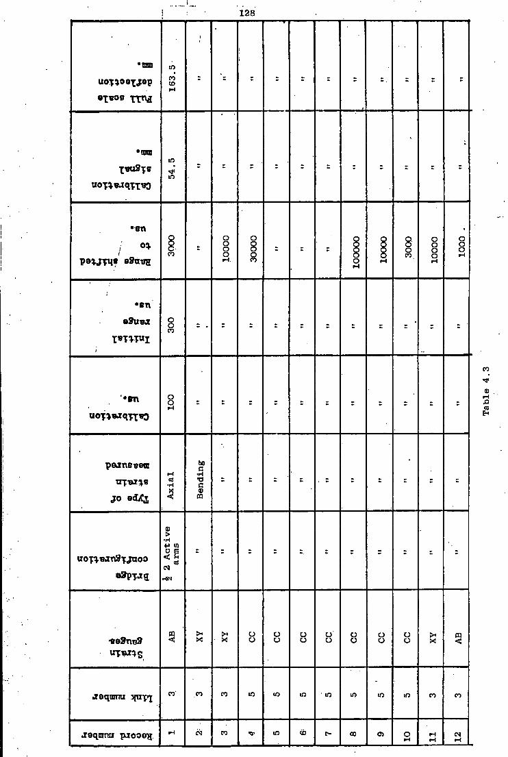
128
•mm
uoTioexjep
16
3.5
1
' = r
*ron
54.5
- = = =
•en
/ °* 3000
r
OO
OO
t 3000
0
= = =
1000
00 OOOOT 30
00
1000
0
1000
.
•
•en
...
o o CO
- J =
r s . •
•en
uoT*«xqTt*3
OOT
peanEBern
j o edA*i Ax
ial
Ben
ding
•
uo-paBanSTjuoo
<D >
•H +J (0 O E < K
OS CM
CP < X!
>* • X
u o o o o o C J '
o o C J
o O o o X! m <
•isqitmu ypiyi CO' CO co m m m m m m m co CO
.reqnmu pjootrg rH CM CO m ib r - CO en O i H
rH rH
CM rH

129
uo-f ioexjop
163.
5
163.
3"
163.
5
-
•tntn m
m 05 54
.5
= = =
•sn O o o o o o O O O 8 - - s . 8 o
o s o
: . 0 - 8 O
CO O rH CO o O co T-t CO T-i
•en o o
O O
o o
co I H CO
•«n o o
O CO
o o
T-i i H
bO C i H •
• H CO t t T l M l B •D
c • H = - : : : - -
CO < 1
j o scLCi •
> • H in +»a
U O T I W H S T J U O O <fl CO
CM
H N
ee9n«9 o o
>> X
= < =
cj o
= • r - r X <
aeqnmu 3ftiT»i m ' co CO co CO m • m . m m m CO CO
Jaq.tsnu pjooe^ CO in CD co 05 i o
1 N 1 -M CM
CO CM CM

i 130 1
•mo
163.
5
i
•nun lO
lO
-=
•en
.< ° * peojifus eStxtrg 30
000
1000
0
r 30
00
• sn
e9u«x O o CO
r
•
•
•0T\ o o f-l
: =
•
peanenetn
j o 8<LCi Ben
ding
r
Ax
ial
uoTiBJn3xjuoo
J 2
Act
ive
arm
s : =
:«e3ntj9 o o ><
X! X ! . X
•xequmu stxixfj . lO" CO CO CO
jsqmrtu racoon i n CM
ID CM
C -CM
CO CM
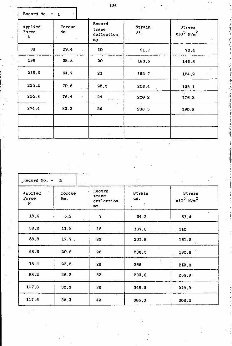
131
Record No. - l
A p p l i e d Force
N
Torque . Nm
Record t r ace d e f l e c t i o n nun
S t r a i n us .
Stress x l O 5
N / m
2
98 29.4 10 91.7 73.4
196 58.8 20 183.5 146.8
215.6 64.7 21 192.7 154.2
235.2 70.6 22.5 206.4 165.1
254.8 76.4 24 220.2 176.2
274.4 82.3 26 238.5 190.8
Record No. - 2
A p p l i e d Force
N
Torque Nm.
Record t r ace d e f l e c t i o n mm
S t r a i n us.
Stress
x l O 5 N/m 2
19.6 5.9 7 64.2 51.4
39.2 11.8 15 137.6 110
58.8 17.7 . 22 201.8 161.5
68.6 20.6 26 238.5 190.8
78.4 23.5 29 266 212.8
88.2 26.5 32 293.6 234.9
107.8 32.3 38 348.6 278.9
117.6 35.3 42 385.3 308.2

132 Record No. - 3
A p p l i e d Force
N
Torque . Nm
Record t r ace d e f l e c t i o n mm
S t r a i n us.
Stress
x l O 5 N/m 2
98 29.4 9 275.2 220.2
117.6 35.3 10 305.8 244.6.
137.2 41.2 12 367 293.6
156.8 47 14 428 .1 342.5
166.6 50 .15 458.7 367
176.4 52.9 18 550.5 440.4
196 58.8 18.5 565.7 452.6
205.8 61.7 19 581 464.8
215.6 64.7 20 611.6 489.3
Record No. - 4
A p p l i e d Force
N •
Torque Nm.
Record t r a c e d e f l e c t i o n mm
S t r a i n us.
Stress
x l O 5 N/m 2 -
49 14.7 3.5 321.1 333.6
147 4 4 . 1 13.5 1238.5 1286.8
245 73.5 23 2110 2192.4
264.6 79.4 25 2293.6 2383
284.2 85.3 27 2477 2573.6
303.8 91 .1 29 2660.5 2764;3

133 Record No. - 5
A p p l i e d Force
N
Torque Nm
Record t r ace d e f l e c t i o n mm
S t r a i n us .
Stress
x l O 5 N/m 2
98 29.4 7.5 688 714.9
147 4 4 . 1 11.5 1055 1096.2
166.6 50 12.5 1146.8 1191.5
186.2 55.9 16 1467.9 1525.1
205.8 61.7 .18 1651.4 1715.8
Record No. - 6
A p p l i e d Force
N
Torque Nm.
Record t r a c e d e f l e c t i o n mm
S t r a i n us .
Stress
x l O 5 N/m 2
49 . 14.7 3.5 321.1 333.6
147 4 4 . 1 . 13 1192.6 1239.2
245 73.5 22.5 2064.2 2144.7
264.6 79.4 24.5 2247.7 2335.4
284.2 85.2 27 2477 2573.6
303.8 91 .1 29 2660.5 2764.3

134
Record No. - 7
App l i e d Force
N
Torque Nm
Record t r a c e d e f l e c t i o n mm
S t r a i n us.
S t r e s s x l O 5 N/m2
49 14.7 4 366.9 381.3
147 44.1 13 1192.7 1239. 2*.
245 73.5 22 2018.3 2097
264.6 79.4 24 2201.8 2287.7
284.2 85.2 •25.5 2339.4 2430.7
303.8 91.1 26.5 2431.2 2526
Record No. - 8
A p p l i e d Force
N
Torque Nm.
Record t r a c e d e f l e c t i o n mm
S t r a i n us. •
S t r e s s x l O 5 N/m2
98 29.4 3 917.4 953.2
147 44.1 3.5 1070.3 1112
166.6 50 4 1223.2 1271
186.2 55.9 4.5 1376.1 1429.8
205.8 61.7 . 5 1529 1588.7
225.4 67.6 5.5 1682 1747.5
245 73.5 6 1834.8 1906.4

135
Record No. - 9
Ap p l i e d Force
N
Torque . . Nm
Record t r a c e d e f l e c t i o n mm
S t r a i n us.
S t r e s s x l O 5 N/m2
19.6 5.9 2 61.1 63.5
39.2 11.7 4 122.3 127
58.8 17.6 8 244.6 254.2
78.4 23.5 12 367 381.3
98 29.4 17. 520 540.1
117.6 35.3 22 672.8 699
Record No. - 10
A p p l i e d Force
N
19.6
39.2
49
58.8
Torque Nm.
5.9
11.7
14.7
17.6
Record t r a c e d e f l e c t i o n mm
6.5
22
30.5
41
S t r a i n us.
59.6
201.8
279.8
376.1
S t r e s s x l O 5 N/m2
62
209.7
290.7
390.8
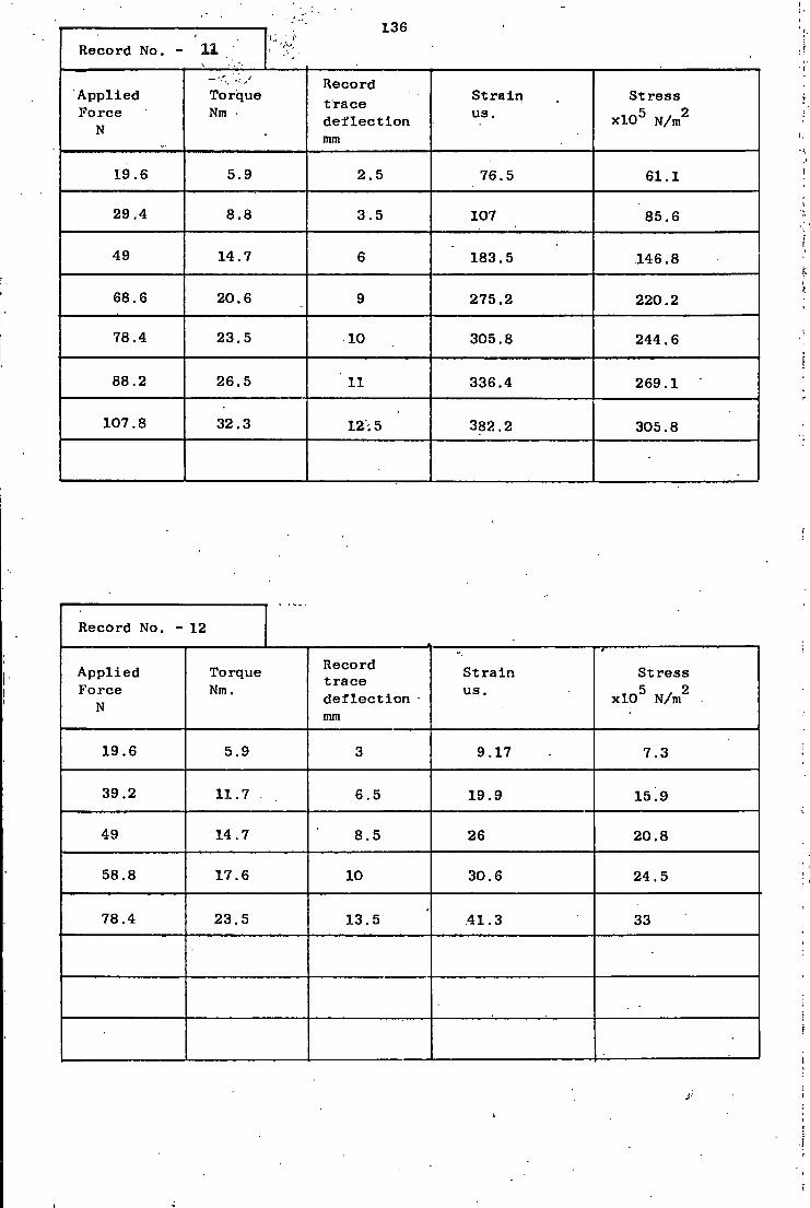
136
Record No. - 11
A p p l i e d Force
N
Torque Nm •
Record t r a c e d e f l e c t i o n mm
S t r a i n us.
S t r e s s x l O 5 N/m2
19.6 5.9 2.5 76.5 61.1
29.4 8.8 3.5 107 85.6
49 14.7 6 183.5 146.8
68.6 20.6 9 275.2 220.2
78.4 23.5 10 305.8 244.6
88.2 26.5 11 336.4 269.1
107.8 32.3 12.5 382.2 305.8
Record No. - 12
A p p l i e d Force
N
Torque Nm.
Record t r a c e d e f l e c t i o n nun
S t r a i n us.
S t r e s s x l O 5 N/m2
19.6 5.9 3 9.17 7.3
39.2 11.7 6.5 19.9 15.9
49 14.7 8.5 26 20.8
58.8 17.6 10 30.6 24.5
78.4 23.5 13.5 .41.3 33
J'
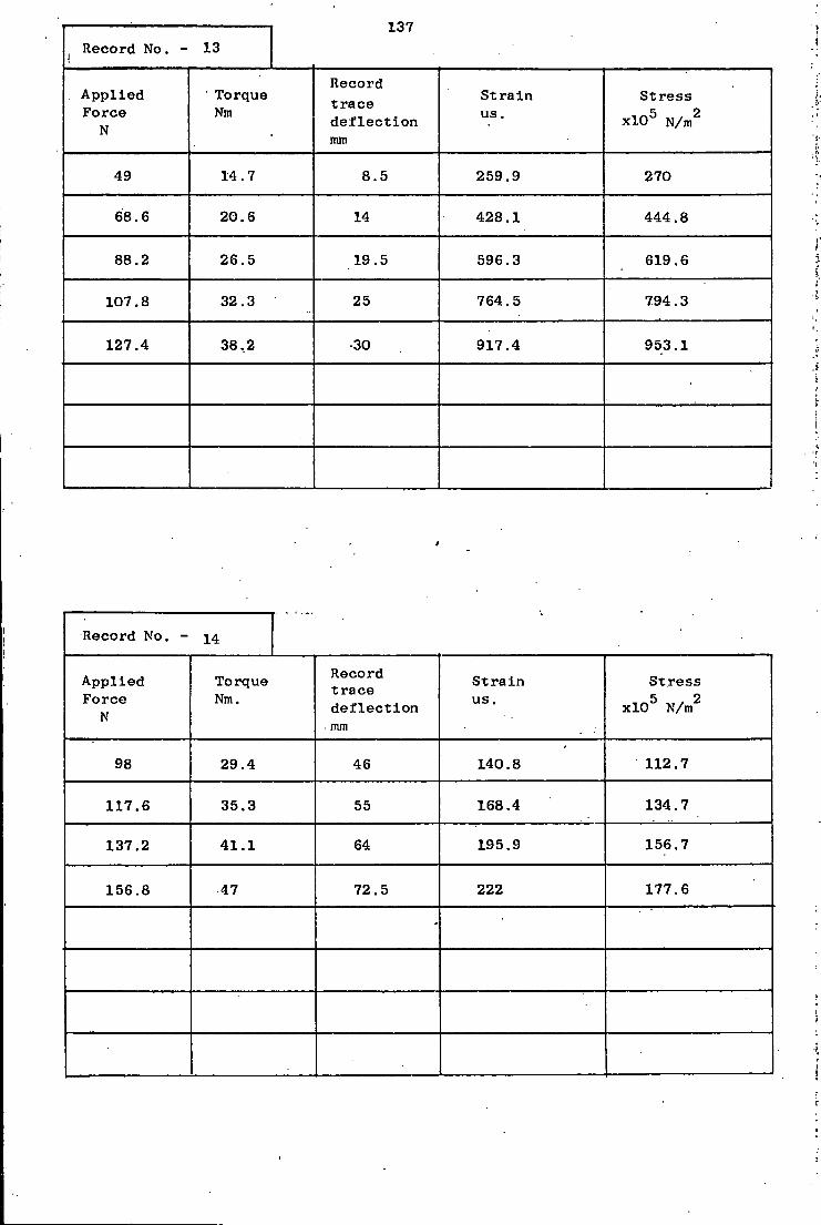
137 Record No. - 13
A p p l i e d Force
N
Torque Nm
Record t r a c e d e f l e c t i o n mm
S t r a i n us.
S t r e s s x l O 5 N/ m
2
49 14.7 8.5 259.9 270
68.6 20.6 14 428.1 444.8
88.2 26.5 19.5 596.3 619.6
107.8 32.3 25 764.5 794.3
127.4 38,2 •30 917.4 953.1
Record No. - 14
App l i e d F o r c e
N
98
117.6
137.2
156.8
Torque Nm.
29.4
35.3
41.1
47
Record t r a c e d e f l e c t i o n mm
46
55
64
S t r a i n us.
140.8
168.4
195.9
S t r e s s x l O 5 N/m2
112.7
72.5 222
134.7
156.7
177.6
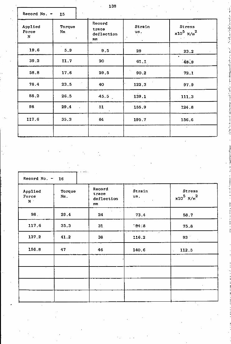
138 Record No. - 15
A p p l i e d Force
N
Torque Nm
Record t r a c e d e f l e c t i o n mm
S t r a i n us.
S t r e s s x l O 5 N/m2
19.6 5.9 9.5 29 23.2
39.2 11.7 20 61.1 •
48i 9
58.8 17.6 29.5 90.2 72.1
78.4 23.5 40 122.3 97.9
88.2 26.5 •45.5 139.1 111.3
98 29.4 51 155.9 124.8
117.6 35.3 64 195.7 156.6
Record No. - 16
A p p l i e d Force
N
Torque Nm.
Record t r a c e d e f l e c t i o n mm
S t r a i n us.
S t r e s s x l O 5 N/m2
98. 29.4 24 73.4 58.7
117.6 35.3 31 •94-; 8 75.8
137.2 41.2 38 116.2 93
156.8 47 46 140.6 112.5
•

139 Record No. - 17
A p p l i e d Force
N
Torque Nm
Record t r a c e d e f l e c t i o n mm
S t r a i n us.
S t r e s s x l O 5 N/m2
19.6 5.9 2 6.1 4.9
39.2 11.7 6 18.3 14.7
58.8 17.6 13.5 41.3 33
78.4 23.5 21.5 65.8 52.6
98 29.4 30 91.7 73.4
117.6 35.3 40 122.3 97.9
Record No. - 18
A p p l i e d Force
N
Torque Nm.
Record t r a c e d e f l e c t i o n mm
S t r a i n us.
S t r e s s x l O 5 N/m2
19.6 5.9 2.5 22.9 23.8
39.2 11.7 10.5 96.3 100
58.8 17.6 22 201.8 209.7
68.6 20.6 22 201.8 209.7
78.4 23.5 24.5 224.8 233.5
98 29.4 31.5 289 300.3

Record No. - 19 140
A p p l i e d Force
N
* Torque . Nm
Record t r a c e d e f l e c t i o n mm
S t r a i n us.
S t r e s s x l O 5 N/m2
98 29.4 3 275.2 286
147 44.1 5.5 504.6 524.3
166.6 50 6 550.5 571.9
186.2 55.8 7 642.2 667.2
205.8 61.7 8 733.9 762.6
225.4 67.6 9 825.7 857.9
245 73.5 9.5 871.5 905.5
. r
Record No. - 20
A p p l i e d Force
N
Torque Nm.
Record t r a c e d e f l e c t i o n mm
S t r a i n us.
S t r e s s x l O 5 N/m2
49 14.7 2 183.5 190.6
147 44.1 6.5 596.3 619.6
. 245 73.5 10.5 963.3 1000.9
264.6 79.4 - - —
-
•
i.

141
Record No. - 21
App l i e d Force
N
Torque Nm
Record t r a c e d e f l e c t i o n mm
S t r a i n us.
S t r e s s x l O 5 N/m2
98 29.4 11 336.4 349.5
147 44.1 18 550.5 571.9
166.6 50 20 611.6 635.5.
186.2 55.9 23 703.3 730.8
205.8 61.7 26 795.1 826.1
225.4 62.6 29 886.8 921.4
235.2 70.5 31 948 985
245 73.5 34 . 1039.7 1080.3
.'• 1 T !
Record No. - 22
A p p l i e d Force
N
Torque Nm.
Record t r a c e d e f l e c t i o n mm
S t r a i n us.
S t r e s s x l O 5 N/m2
49 14.7 4.5 137.6 143
68.6 20.6 7 214 222.4
88.2 26.5 10 305.8 317.7
107.8 32.3 13 397.5 413
205.8 61.7 21.5 657.5 683.1

142
Record No. - 23
Ap p l i e d Force
N
Torque Nm
Record t r a c e d e f l e c t i o n mm
S t r a i n us.
S t r e s s x l O 5 N/m2
98 29.4 10.5 96.3 77
117.6 35.3 19 174.3 139.4
137.2 41.2 21.5 197.2 157.8
156.8 47 24.5 224.8 179.8
176.4 52.9 28 256.9 205.5
186.2 55.9 29 266 212.8
196 58.8 31 284.4 227.5
205.8 61.7 34 311.9 249.5
Record No. - 24
Ap p l i e d Force
N
Torque Nm.
Record t r a c e d e f l e c t i o n mm
S t r a i n us.
S t r e s s x l O 5 N/m2
19.6 5.9 6 5.5 4.4
39.2 11.7 25 22.9 18.3
58.8 17.6 50 45.9 36.7
78.4 23.5 77 70.6 56.5
98 29.4 115 105.5 84.4
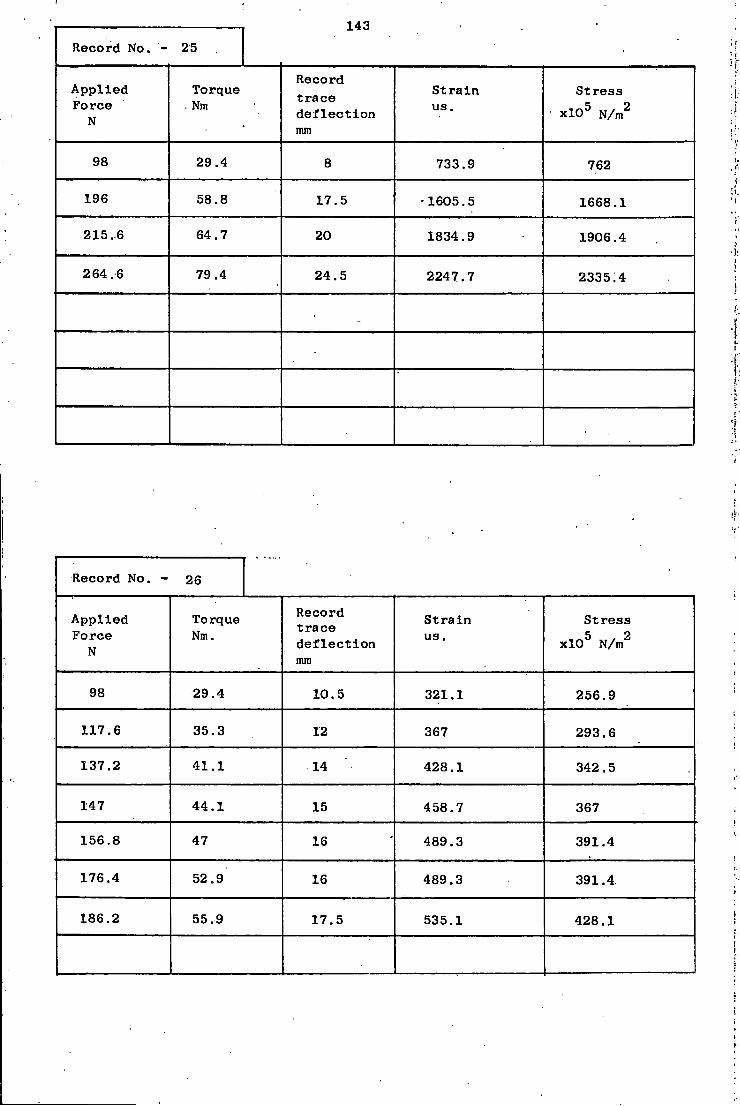
Record No. - 25 143
A p p l i e d Force
N
Torque . Nm
Record t r a c e d e f l e c t i o n mm
S t r a i n us.
S t r e s s x l O 5 N/m2
98 29.4 8 733.9 762
196 58.8 17.5 -1605.5 1668.1
215.6 64.7 20 1834.9 1906.4
264.6 79.4 24.5 2247.7 233514
Record No. - 26
A p p l i e d Force
N
Torque Nm.
Record t r a c e d e f l e c t i o n mm
S t r a i n us.
S t r e s s x l O 5 N/m2
98 29.4 10.5 321.1 256.9
117.6 35.3 12 367 293.6
137.2 41.1 14 428.1 342.5
147 44.1 15 458.7 367
156.8 47 16 489.3 391.4
176.4 52.9 16 489.3 391.4
186.2 55.9 17.5 535.1 428.1

144
Record No. - 27 •
A p p l i e d Force
N
Torque . Nm
Record t r a c e d e f l e c t i o n mm
S t r a i n us.
S t r e s s x l O 5
N/m2
98 29.4 9.5 290.5 232.4
117.6 35.3 11 336.4 269.1
127.4 38.2 11.5 351.7 281.3
137.2 41.1 12 367 293.6
156.8 47 .13.5 412.8 330.3
Record No. - 28
A p p l i e d Force
N
Torque Nm,
Record t r a c e d e f l e c t i o n mm
S t r a i n us.
S t r e s s x l O 5 N/m2
98 29.4 17.5 160.5 128.4
196 58.8 34 311.9 249.5
215.6 64.7 39 357.8 286.2
-
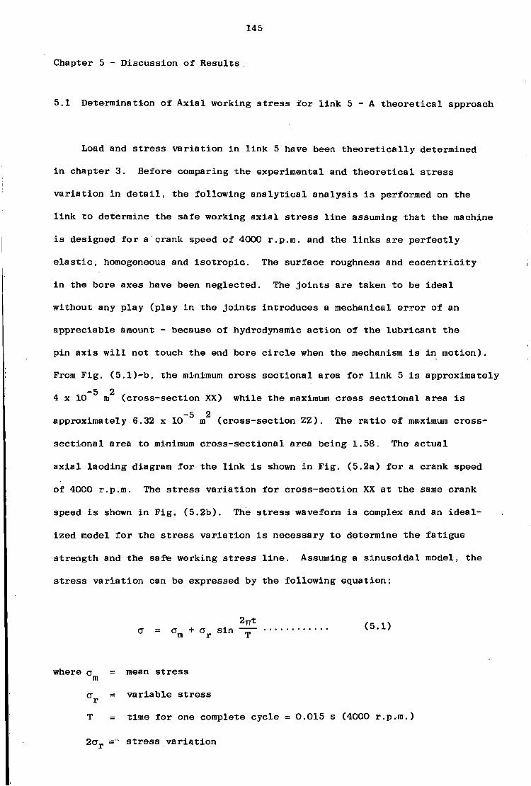
145
Chapter 5 - D i s c u s s i o n of R e s u l t s
5.1 Determination of A x i a l working s t r e s s f o r l i n k 5 - A t h e o r e t i c a l approach
Load and s t r e s s v a r i a t i o n i n l i n k 5 have been t h e o r e t i c a l l y determined
i n chapter 3. Before comparing the experimental and t h e o r e t i c a l s t r e s s
v a r i a t i o n i n d e t a i l , the f o l l o w i n g a n a l y t i c a l a n a l y s i s i s performed on the
l i n k to determine the s a f e working a x i a l s t r e s s l i n e assuming t h a t the machine
i s designed f o r a crank speed of 4000 r.p.m. and the l i n k s a r e p e r f e c t l y
e l a s t i c , homogeneous and i s o t r o p i c . The s u r f a c e roughness and e c c e n t r i c i t y
i n the bore axes have been neglected. The j o i n t s a r e taken to be i d e a l
without any p l a y ( p l a y i n the j o i n t s i n t r o d u c e s a mechanical e r r o r of an
a p p r e c i a b l e amount - because of hydrodynamic a c t i o n of the l u b r i c a n t the
p i n a x i s w i l l not touch the end bore c i r c l e when the mechanism i s i n motion).
From F i g . (5.1)-b, the minimum c r o s s s e c t i o n a l area f o r l i n k 5 i s approximately -5 2
4 x 10 m ( c r o s s - s e c t i o n XX) w h i l e the maximum c r o s s s e c t i o n a l area i s -5 2
approximately 6.32 x 10 m ( c r o s s - s e c t i o n Z Z ) . The r a t i o of maximum c r o s s -
s e c t i o n a l area to minimum c r o s s - s e c t i o n a l area being 1.58. The a c t u a l
a x i a l l a o d i n g diagram f o r the l i n k i s shown i n F i g . (5.2a) f o r a crank speed
of 4000 r.p.m. The s t r e s s v a r i a t i o n f o r c r o s s - s e c t i o n XX a t the same crank
speed i s shown i n F i g . ( 5 . 2 b ) . The s t r e s s waveform i s complex and an i d e a l
i z e d model f o r the s t r e s s v a r i a t i o n i s n e c e s s a r y to determine the f a t i g u e
s t r e n g t h and the s a f e working s t r e s s l i n e . Assuming a s i n u s o i d a l model, the
s t r e s s v a r i a t i o n can be expressed by the f o l l o w i n g equation:
2 n t (5.1) a = o + o" s i n m r T
where a mean s t r e s s m
ex. v a r i a b l e s t r e s s r T time f o r one complete c y c l e = 0.015 s (4000 r.p.m.)
s t r e s s v a r i a t i o n

; 146 F i g 5.1
l i n k 3 and Link 5 (clearances are extremely exaggerated)
i U
14 U
ATOSS section of the 7 BOLT
A Cross section UU
'A A >
'A 23 Cross section XX
A Scale x2
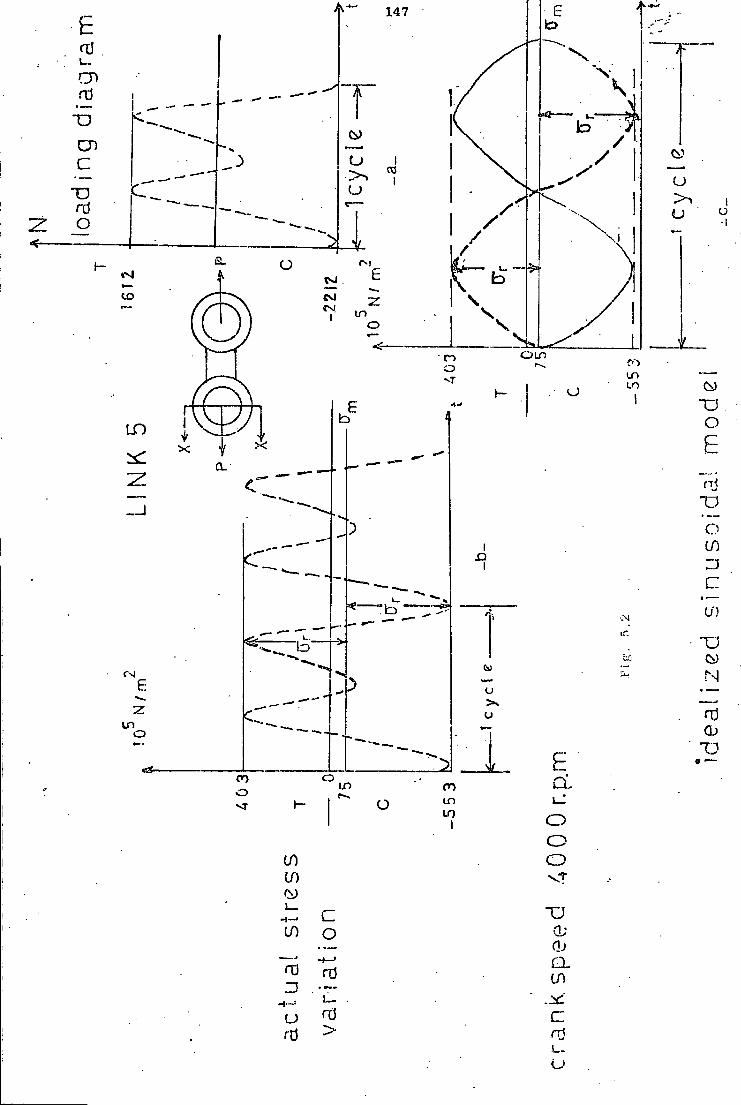
147
A
u
o v .
a. f— $4 « 5
O L D
o LO £ a.
H3 D J a
0)
CM
o a CO L i )
o O O if)
If) v?
CO o -4—> Q.
If)

148
S u b s t i t u t i n g the numerical v a l u e s eq. (5.1) y i e l d s :
a = -75 x 10° + 478 x 10 s i n 2 n t
0T015 (4000 r.p.m.)
which i s shown i n F i g . (5.3)
S t r e s s r a t i o i s determined as:
n crm,„ 553 x 10 . _„ R = mm = - = -1.37 Jmax 103 x 10
The f a c t o r of s a f e t y F.S can now be c a l c u l a t e d as:
max y-p F.S
F.S. = 17.6 x 1 0 7 = 3.18 553 x 1 0 5
where the y i e l d point s t r e n g t h o* = 17.6 x 10 i s taken from F i g . (4.8)
There a r e a number of d i f f e r e n t e m p i r i c a l f a i l u r e equations d e f i n i n g
the r e l a t i o n between the v a r i a b l e and mean s t r e s s e s . Three of the most
commonly used r e l a t i o n s a r e employed to c a l c u l a t e the endurance s t r e n g t h <j
as i n the f o l l o w i n g :
a - Gerber p a r a b o l i c r e l a t i o n ;
c re/ + VW = 1
7 2 where CT = u l t i m a t e t e n s i l e s t r e n g t h = 22.4 x 10 N/m (From F i g . ( 4 . 8 ) )
u l t
CT = + 4.78 x 1 0 7 N/m2
e —

149
b - Modified Goodman R e l a t i o n ;
m + u l t
+ 4.62 x 10 N/m
Soderberg r e l a t i o n
m yp
CT = + 4.58 x 1 0 7 N/m2
e
The s a f e working a x i a l s t r e s s l i n e , employing Soderberg's c r i t e r i a i s
shown i n F i g . ( 5 . 3 ) . The a x i a l s t r e s s a t a crank speed of 4000'r.p.m. can
h a r d l y be approximated by Gerber's c r i t e r i a and i s above the approximate
l i n e s of f a i l u r e by Soderberg and modified Goodman methods, w h i l e the
a x i a l s t r e s s a t a crank speed of 25000'^.p.m. i s s l i g h t l y under the conser- /<:
v a t i v e s a f e s t r e s s l i n e approximated by Soderberg c r i t e r i a . A good d i s c u s s i o n
of the above procedure can be found i n ( 20 ) ( 26 ) and ( 5 ) . I t
should be noted t h a t the v a l u e s c a l c u l a t e d a r e only rough e s t i m a t e s . No
standard b a s i s f o r o b t a i n i n g working f a t i g u e s t r e s s r e l a t i o n s has been
u n i v e r s a l l y accepted. The f a t i g u e s t r e n g t h i s a l s o a f f e c t e d by the c l e a r a n c e
between the p i n and hole, the d i s t r i b u t i o n of shear s t r e s s around the hole
boundary, l u b r i c a t i o n , p i n m a t e r i a l and p i n bending e f f e c t s , s u r f a c e c o n d i t i o n s ,
p r i o r overloads, environmental e f f e c t s , m a t e r i a l and manufacturing e f f e c t s .
The c a l c u l a t e d endurance l i m i t s t r e s s , o" , i s the maximum completely r e v e r s i n g
s t r e s s t h a t the l i n k can s u s t a i n f o r an u n l i m i t e d number of c y c l e s without
f a t i g u e f a i l u r e . I f the completely r e v e r s e d s t r e s s i s h i g h e r than a , the
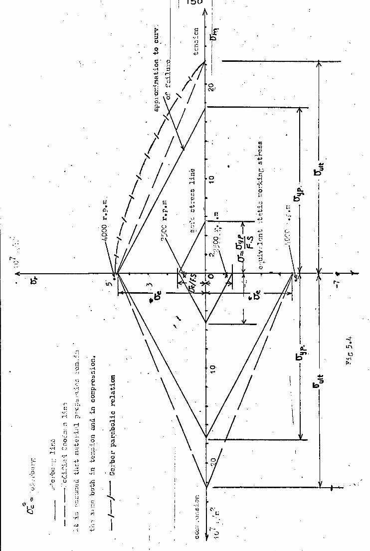
i I O U
1 a:
4 +» r-l
•r. HH / CM'
a.
10
/ 10 £1
/ 11
\ I.)
VJ O- 3JW o
'S
•
t 3
Id
•J o
\ I
ri
t
0}
) r

151
f a i l u r e can be expected to take p l a c e a f t e r some f i n i t e number of c y c l e s .
The higher the s t r e s s the fewer w i l l be the c y c l e s before f a i l u r e can be
expected.
5.2 T h e o r e t i c a l and experimental a x i a l s t r e s s range v a r i a t i o n w i t h the
crank speed i n l i n k 5
The v a r i a t i o n of the experimental a x i a l s t r e s s range f o r l i n k 5 w i t h
the crank speed and w i t h the square of the crank speed a r e presented i n
F i g u r e s 4.9 and 4.13 r e s p e c t i v e l y . Due to gauge i n s t a l l a t i o n and s t r u c t
u r a l f a i l u r e s (due to s l i p ) , c a u s i n g s e v e r e mechanical damage; the maximum
crank arm speed could not be i n c r e a s e d beyond about 25000 r.p.m. although
v a r i o u s u n s e c c e s f u l attempts have been made to reach 3000 r.p.m. or more.
The speed f l u c t u a t i o n e f f e c t has been n e g l e c t e d ( a s e x p l a i n e d i n chapter 4,
+ 0.08 experimental speed f l u c t u a t i o n c o e f f i c i e n t has been regarded as
being of no importance). The b a s i c f a c t o r s i n t r o d u c i n g e r r o r a r e i d e n t i f i e d
as f o l l o w s ;
1 - S e n s i t i v i t y and a c c u r a c y of the measuring d e v i c e s employed i n the
experimental set-up.
2 - E f f e c t of the h o s t i l e enivronment
3 - E f f e c t of the a d d i t i o n a l moment of i n e r t i a introduced by the
s t r a i n - g a u g e s and t h e i r l e a d s on the l i n k s
4 - E r r o r i n experimental determination of the c r o s s - s e c t i o n a l a r e a s
and v a l u e s of Young's moduli.
5 - P e r s o n a l e r r o r i n i n t e r p r e t i n g the data (u.v. T r a c e s ) .
I n g e neral the experimental r e s u l t s a r e i n good agreement w i t h the
c a l c u l a t e d a x i a l s t r e s s range v a l u e s f o r l i n k 5. By a p p l y i n g method of
l e a s t squares the experimental a x i a l s t r e s s range curve i s approximated by
the f o l l o w i n g s t r a i g h t l i n e
100 n
y = 38.6 x - 7.7
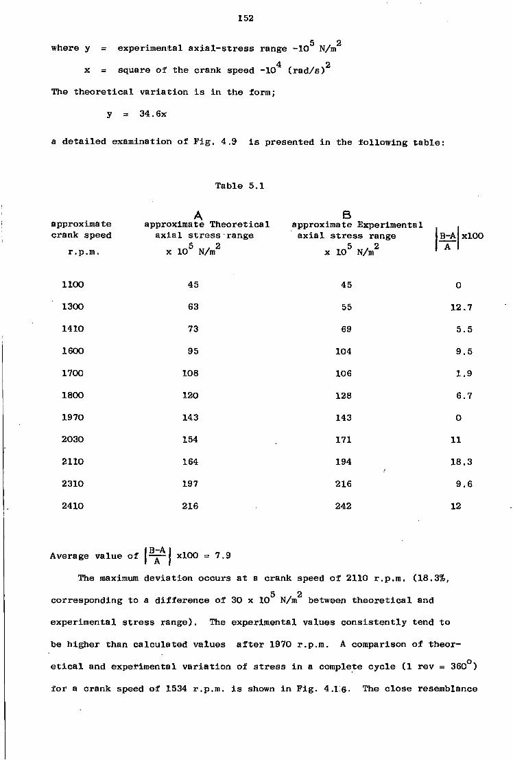
152
5 2 where y = experimental a x i a l - s t r e s s range -10 N/m
4 2
x = square o f the crank speed -10 ( r a d / s )
The t h e o r e t i c a l v a r i a t i o n i s i n the form;
y = 34.6x a d e t a i l e d examination of F i g . 4.9 i s presented i n the f o l l o w i n g t a b l e :
T able 5.1
A B approximate approximate T h e o r e t i c a l approximate Experimental . crank speed a x i a l s t r e s s range a x i a l s t r e s s range |B-A|xlOO
r.p.m. x 1 0 5 N/m2 x 1 0 5 N/m2
1100 45 45 0
1300 63 55 12.7
1410 73 69 5.5
1600 95 104 9.5
1700 108 106 1.9
1800 120 128 6.7
1970 143 143 0
2030 154 171 11
2110 164 194 18.3
2310 197 216 9.6
2410 216 242 12
Average v a l u e of | xlOO = 7.9
The maximum d e v i a t i o n occurs a t a crank speed o f 2110 r.p.m. (18.3%, 5 . 2
corresponding to a d i f f e r e n c e of 30 x 10 N/m between t h e o r e t i c a l and
experimental s t r e s s range). The experimental v a l u e s c o n s i s t e n t l y tend to
be higher than c a l c u l a t e d v a l u e s a f t e r 1970 r.p.m. A comparison of theor
e t i c a l and experimental v a r i a t i o n of s t r e s s i n a complete c y c l e (1 rev = 360°)
f o r a crank speed of 1534 r.p.m. i s shown i n F i g . 4.16. The c l o s e resemblance
153
between the waveforms i s s i g n i f i c a n t . An approximate s h i f t of 20 i s
observed a t the two peak t e n s i l e s t r e s s v a l u e s , between the two waveforms.
The sample of the recorded a x i a l s t r e s s waveform over one c y c l e shown i n
F i g . 4 . I S i s i n b e t t e r agreement w i t h the c a l c u l a t e d waveform than the
experimental waveform presented and compared w i t h the c a l c u l a t e d waveform
by Alexander and Lawrence( 15), f o r bending s t r a i n v a r i a t i o n i n the coupler
o f a. model four-bar p l a n a r mechanism.

' 154
5.3 C a l c u l a t i o n of e c c e n t r i c i t y from experimental data, f o r l i n k s 5 and 3
a - L i n k 5
From F i g . 4.4 - s t a t i c bending s t r a i n t e s t f o r l i n k 5, the equation
of the l i n e approximating a x i a l s t r e s s v a r i a t i o n w i t h the a p p l i e d torque i s
a ax = 12.7
. „ . , _ _ A x i a l f o r c e where cr = a x x a l s t r e s s on the c r o s s sectxon = ax c r o s s - s e c t i o n a l area
T = Torque a p p l i e d to the crank arm v i a the l e v e r
and the equation of the s t r a i g h t l i n e approximating the bending s t r e s s
v a r i a t i o n w i t h the a p p l i e d torque i s :
a J T £ = 26.6
M where cr = bending s t r e s s = C
I
where I = Moment of i n e r t i a of the c r o s s s e c t i o n
c = Maximum d i s t a n c e from the n e u t r a l a x i a M = F .d ax
where d = e c c e n t r i c i t y
The r a t i o of the bending s t r e s s to a x i a l s t r e s s i s
K = °"b = 2 CTax
The e c c e n t r i c i t y d can now be c a l c u l a t e d a s :
K = CTb = 2 = d.c.A. (5 2 ) CTax 1
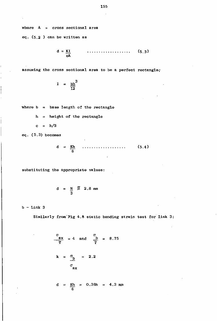
155
where A = c r o s s s e c t i o n a l area
eq. (5.2 ) can be w r i t t e n as
d = KI (5.3) cA
assuming the c r o s s s e c t i o n a l area to be a p e r f e c t rectangle.;-
I = b h 3
12
where b = base le n g t h of the r e c t a n g l e
h = h e i g h t of the r e c t a n g l e
c = h/2
eq. (5.3) becomes
d = Kh (5.4) 6
s u b s t i t u t i n g the a p p r o p r i a t e v a l u e s :
d = H ~ 2.8 mm 3
b - L i n k 3
S i m i l a r l y from F i g 4.R s t a t i c bending s t r a i n t e s t f o r l i n k 3
a a ax = 4 and _b = 8.75 T T
k = o"b = 2.2
a ax
d = Kh = 0.36h = 4.3 mm 6
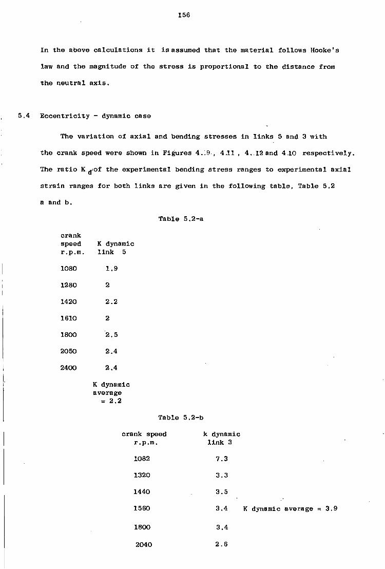
156
I n the above c a l c u l a t i o n s i t i s assumed t h a t the m a t e r i a l f o l l o w s Hooke's
law and the magnitude of the s t r e s s i s p r o p o r t i o n a l to the d i s t a n c e from
the n e u t r a l a x i s .
5.4 E c c e n t r i c i t y - dynamic c a s e
The v a r i a t i o n of a x i a l and bending s t r e s s e s i n l i n k s 5 and 3 w i t h
the crank speed were shown i n F i g u r e s 4.!9 , 4.11 , 4..12 and 4.10 r e s p e c t i v e l y .
The r a t i o K ^ o f the experimental bending s t r e s s ranges to experimental a x i a l
s t r a i n ranges f o r both l i n k s a r e given i n the f o l l o w i n g t a b l e , Table 5.2
a and b.
Tab l e 5.2-a
crank speed K dynamic r.p.m. l i n k 5
1080 1.9
1280 2
1420 2.2
1610 2
1800 2.5
2050 2.4
2400 2.4
K dynamic average
= 2.2
Tab l e 5.2-b
crank speed k dynamic r.p.m. l i n k 3
1082 7.3
1320 3.3
1440 3.5
1560 3.4 K dynamic average = 3.9
1800 3.4
2040 2.6

157
Average value of K dynamic f o r l i n k 5 i s i n good agreement w i t h the K
v a l u e f o r the s t a t i c c a s e w h i l e the average value of K dynamic f o r l i n k 3
i s about 1.77 times of the K v a l u e obtained f o r the s t a t i c c a s e
5. 5 Determination of A x i a l working s t r e s s f o r l i n k 3 - A t h e o r e t i c a l approach
Applying the same assumptions and method shown i n s e c t i o n 5.1., the
working s t r e s s i s determined f o r the minimum c r o s s s e c t i o n a l area ( c r o s s
s e c t i o n UU, F i g . 5.1) as i n the f o l l o w i n g ;
The loading diagram and a x i a l c y c l i c s t r e s s v a r i a t i o n a r e shown i n F i g . 5.4
f o r the c r o s s s e c t i o n a t a crank speed of 4000 r.p.m. -5 2
A = c r o s s s e c t i o n a l area 11 x 10 m
CT = 302 x 1 0 5 N/m2
max a . = -88 x 1 0 5 N/m2
min a 107 x 1 0 5 N/m2
m °~r = 195 x 1 0 5 N/m2
2a = 390 x 1 0 5 N/m2
'r 0.015 s
u s i n g eq. (5.1) the a c t u a l s t r e s s p a t t e r n i s approximated by the f o l l o w i n g
s i n u s o i d a l model:
CT = 107 x 1 0 5 + 195 x 1 0 5 s i n 2 n t 0.015
which i s shewn i n F i g . (5.4)
The s t r e s s r a t i o i s :
min R = = -0.3
CT max

158
From F i g (4.8)
o- = 11.4 x 1 0 7 N/m2
CTult = 1 2 , 4 x 1 q 7 N / i " 2
The f a c t o r of s a f e t y can be c a l c u l a t e d as
max F.S
F.S * 3.77
7 2 Soderberg r e l a t i o n g i v e s an endurance s t r e n g t h of 2.15 x 10 N/m . c&
7 2
c a l c u l a t e d by modified Goodman r e l a t i o n i s 2.13 x 10 N/m . The working
s t r e s s diagram i s shown i n F i g . (5.5 ) . A x i a l s t r e s s a c t i n g on the
c r o s s s e c t i o n i s above the Soderberg l i n e . C r o s s s e c t i o n MM . ( F i g .
5.1) i s i l s o represented on the same diagram.
5.6 T h e o r e t i c a l and experimental a x i a l s t r e s s range v a r i a t i o n w i t h the
crank speed i n l i n k 3.
The v a r i a t i o n of the experimental a x i a l s t r e s s range f o r l i n k 3 w i t h
the crank speed and w i t h the square of the crank speed a r e presented i n
F i g u r e s 4.12 and 4.13: r e s p e c t i v e l y . Crank speed could not be i n c r e a s e d
beyond about 2100 r.p.m. (due t o gauge i n s t a l l a t i o n f a i l u r e s , and d r i f t i n
the u.v. t r a c e s ) . By ap p l y i n g the method of l e a s t squares the experimental
a x i a l s t r e s s range curve i s approximated by the s t r a i g h t l i n e
y = 21.8x + 11.4
5 , 2 where y = experimental a x i a l s t r e s s range -10 N/m
4 2 x = square of the crank speed -10 ( r a d / s )

159
the ' t h e o r e t i c a l v a r i a t i o n i s i n the form:
y = 21.4x
a d e t a i l e d examination of F i g . 4.12 i s presented i n the f o l l o w i n g t a b l e :
T able 5.3
approximate crank speed
r.p.m.
1100
1260
1430
1550
1790
1910
2080
2130
Approximate t h e o r e t i c a l a x i a l s t r e s s range
5 . 2 10 N/m
27
36
47
57
75
85
100
105
B Approximate experimental
a x i a l s t r e s s range
1 0 5 N/m2
24
57
70
74
83
94
114
123
B-A 100
11.1
58.3
49
30
10.6
10.6
14
17.1
average value of B-A| xlOO = 25 I A I
which i s about 3 times higher than t h a t of l i n k 5. The experiment v a l u e s
a r e g e n e r a l l y higher than the c a l c u l a t e d v a l u e s . The maximum d e v i a t i o n occurs
a t a crank speed of 1260 r.p.m. ( 5 8 . 3 % ) . A comparison of t h e o r e t i c a l and
experimental c y c l i c a x i a l s t r e s s v a r i a t i o n i s shown i n F i g . 4.15
5.7 Bending s t r e s s e s i n a d i r e c t i o n normal to plane of the mechanism
The v a r i a t i o n of peak to peak bending s t r e s s e s w i t h the crank speed
f o r l i n k s 3 and 5 are shown i n F i g u r e s 4.30 and 4.1-1 r e s p e c t i v e l y .

160
The bending s t r e s s range curves can be approximated by the s t r a i g h t l i n e s :
y = 37x + 150 ( l i n k 3)
y = 104x - 58 ( l i n k 5)
where aga i n :
5 2 y = bending a x i a l s t r e s s range - 10 N/m
2 x = square of crank speed -10 ( r a d / s )
At a crank speed of 4000 r.p.m. the expected bending s t r e s s range v a l u e s 5 2 5 2 f o r the l i n k s 3 and 5 can be c a l c u l a t e d as 800 x 10 N/m and 1767 x 10 N/m
r e s p e c t i v e l y . The expected a x i a l s t r e s s ranges a t the same crank speed f o r the
l i n k s a r e 395 x 1 0 5 N/m2 ( l i n k 3) and 670 x 1 0 5 N/m2 ( l i n k 5 ) ( v a l u e s based
on experimental d a t a ) . The v a r i a b l e s t r e s s v a l u e s a r e w e l l above the endur
ance s t r e n g t h of the l i n k s . The combined e f f e c t of bending and a x i a l
s t r e s s e s (method of s u p e r p o s i t i o n ) a t a crank speed of 4000 r.p.m. would
i n d i c a t e a s t a t e of f a i l u r e .
5.8 S t r e s s d i s t r i b u t i o n i n the l i n k s
The main o b j e c t i v e of the t e s t e x p lained i n s e c t i o n 4.4^:3 was to determine
whether the bending s t r e s s e s a r e due to an i n i t i a l permanent l i n k deformation,
an o f f s e t , or due to the p i n s , t o l e r a n c e and/or c l e a r a n c e e f f e c t s or" other
misalignments which a r e f a c t o r s e x t e r n a l to the l i n k s themselves. A d e t a i l e d
examination of F i g u r e s 4.6 and 4.7 a r e presented i n T a b l e s (5.4 - 7 ) .
R e s u l t s of the t e s t s f o r both l i n k s show t h a t the bending s t r e s s ( z - d i r e c t i o n )
a r e due to e f f e c t s which a r e e x t e r n a l to the l i n k s . The b a s i c f a c t o r s i n t r o
ducing e r r o r to the r e s u l t s a r e i d e n t i f i e d as f o l l o w s :
1 - E f f e c t s of d e v i a t i o n i n the crank angle (90° + 5°)
2 - F r i c t i o n i n the bearings
3 - E f f e c t s of e l a s t i c i t y of the s h a f t s and l i n k s
The p o s s i b l e bending mechanisms a r e shown i n F i g u r e s (5.6) and (5.7)

161
ui • N
Z luomoiu Sufpuag
T a u a u i o u i Suxpuag
as 6
o
eg
CO
CM
: w CO m
i> in
CO
to co
05
UIIII
00 CM
m co CO
m co
CD
co co co
M = Z a Z Xixocjauaooa
co CO
m co
CM
CO
CO
CO
co CO co
IlllU
uiq T U. D = -Q
co CM
CO
CO
CO
CO
CO
CO CO CD
CO
= X B D _ 2 duioOjo ( G A T S S a j d l U O O )
ssoi.ias Suxpuaq aaN o o
co CM
CD O CO m i>
(M oo co
uiq D
. = X BX) + T. d l U O O D
(a^T-suaa s B o a n s Suxpuaq aaf[
o o l> CM
CD m CO 00 O
2 diuooxj = ssa.ias Suxpuaq
+ T 1 3 T X B ( " O f
• s s f u d u i n o ) >i a S n e g
co m co CO
CM oo m o O oo
oo O
CD «# CM
1 (.IlllOO D = s s a j t i s Suipuoq pile T B I X B
( U O T . S U S J , ) m a3neo
(N m
co CD
O ao CM
( Q A i : B S 0 j d u i o o ) .
V / d = XED
CM m o CO
r-
m O
en co CM
O in
O co
m m CD
CD co
• in • N
'onb.to.i, paxTddy co CM
oo m co CM
O co in co
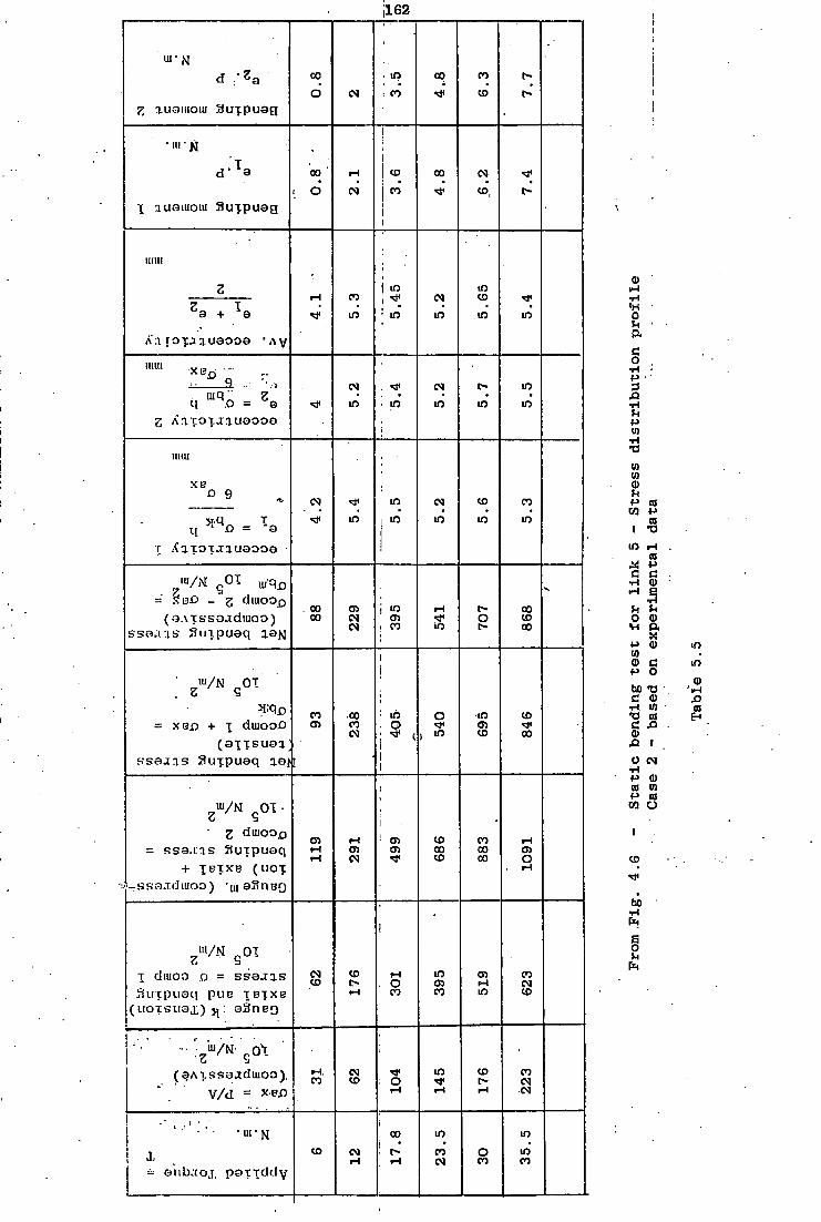
162
'
d :-V co • »Q 00 CO o 6 CM | CO CO
7, xuomoiu 3ufpuag 1
d ; i a oo ' PH CD co CM
: d CM CO CD, t-r auaiuoiu Suxpuag i
1
uiiii 1
Z iH CO
m 5.45
CM
m m CD m m
A'a t o i J i u a o o a ' A y
mui .„_ . ... 9 . /»
U m q o = Z a CM
m . * CM
in c-m
m m
g Ariro j.lauaooa i
IU(U
XB * 9 CM m CM CD CO
V.U T L ( * M X J = "a
^ < m m m in in
r XaT^TJiuaooa
™/N g0 T- uiq f l
(a.vcssojdmoo) ssa. u s Sui.puaq aaN
. co oo 05 CM CM
05 ! " m
t-O t-
co CD oo
• iu/N Ot . Z S
1 i
W e = X B . 0 + i duiooO
CO •oo CO CM
: in O
! ( i
o m 0) CD
CD
co
s s a j j s Suxpuaq iaf I 1 1
Z
WM goi • i
• 2 duioox) = ssa.ins Suipuaq
+ T E T X E ( H O T
CT> <H PH
M CD CM
1 05 en
CD co CD
CO co co 1091
- B K a . T d i u o o ) 'uiaSnBO
Zm/N g0T
1
[ diuoo D = s s a j a s 3 u i : p u a q pue T B T X B
CM CO
CO l> iH
I H , o
CO
m en CO
crs m
CO CM CD
( u o T S i i s x ) : aSneo
( a A t s s a a d u i o o ) .
V/d = * B f l
iH, CO
CM CO ; O
iH
m CD i>
CO CM CM
• ' • ui • N i co m in
= anb.toj, patTddv CD CM
PH ! o
iH CO CM
o CO
m CO
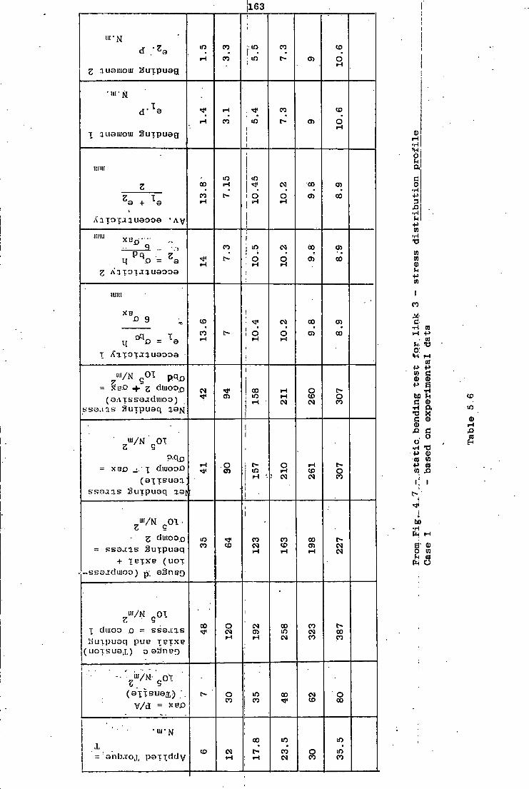
111 • M
Z suauioui Suxpuag
T auouioui Suipuag
CO
CO
CO
163
m
m
CO
co
e'
en
co 6
CO
6
iiiur
Z a + T-e
oo CO
m ! w CM
d
An tocanuaooa "Ay
oo cn
CO
M o = °a 2 A i i a i J i u a o o a
co m o"
CM
O oo cn
co
xe D 9 CO
CO d CM
d r-i
CO en oo
» ' / N g 0 I _ p q j D
= S B . C + g d i u o o £ )
( Q A i s s a j d i u o o ) S B O . U B Sujpuaq q.9M
CM cn
oo m CM
O co CM
O CO
ii/N 0T Z S
= X B f l _!. 1 d l U O O D
( a ^ T s u a a
s s a a n s Suipuaq aaff
.o <n m O CM
CD CM
O CO
3 duioo D
= ssa.ias Suipuaq + T B T X B ( u o x
-ssajdwoo) p, aSiiBQ
m co CO CO CM
CO co
oo cn CM CM
[ diuoo D = s s a a a s Suipuaq put? T E T X I ? (uofsua.x) oaSneo
co o CM
CM cn
co m CM
( a i T s u a x ) V/d = xec
co CM CO
o CO
m co oo CM CD
co co
O co
•UCN
' a n b . t o j , p a T . T d d v CD CM
co m eo CM
O co m m co
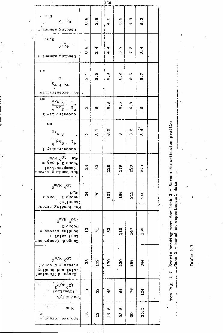
• "1'N
g a u o i u o i u SJuipueg
\ .luoiuo'ui Suipueg
co o
oo CM
164
CO CO
CO t> CO
co 6 CM
l>
lO
CO
l> co
IIIHI co CO
CM
CO
CO
CO in Z a + V
An.totjauaooa *AV IUUI
q .o = °a CD co co
m
CO co co co
1IIIU
X B D 9
q £> = 9
T /f a x o T j a u a o o a
m en CD
m
co
1<
m
= . g diuooo ( a A T S s a a d i u o o )
ssa.us Surpuaq ao>j CM
CO oo
CD CM O
CO CM CM
O CM
p'Qo = X B X ) J 1 C lu iOOD
( a - [ T S u a i s s o a j s Suxpuaq a a j t
CM o CM CO CO
CM H CM
O CM
Z
WM fioi-2 duioo.0
= ssa.:ras auxpuaq + TI3TXB ( U O T
-Bsajduioo) p aSneo
co in I " ! co m o CO
CO
[ CIlUOO D = S S 0 J 3 . S
j > U i p u a C | p i I B T B T X B (Morsiiax) p o3neQ
m co
CM
o o O CO CM
co oo CM
I 1
CO
•zu/&- Q O t (Gitsuaj,) Y/d = X B D
CM CO
CO CO
CD o
o n b . x o j , p a T.xddv CO- CM
00 m
co CM
o CO
m co
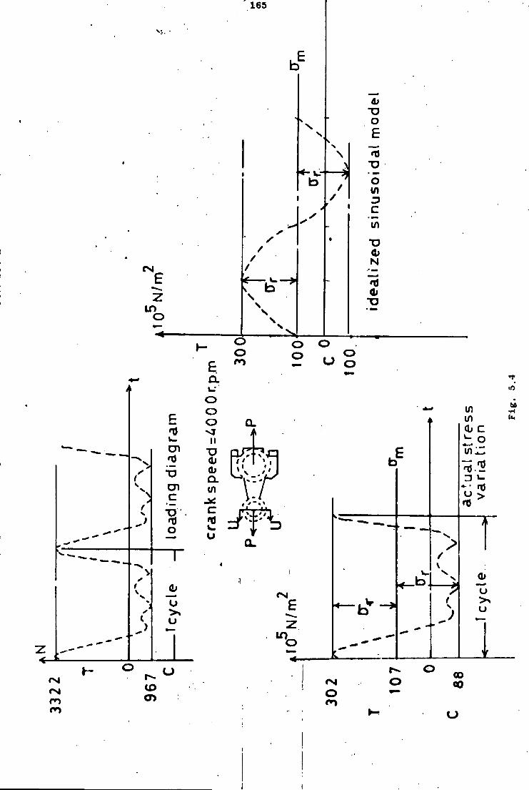
165
V)
in
N
I D
bfi U1
ii in
i
c n in
u
CO CO CD CM CD ro
i
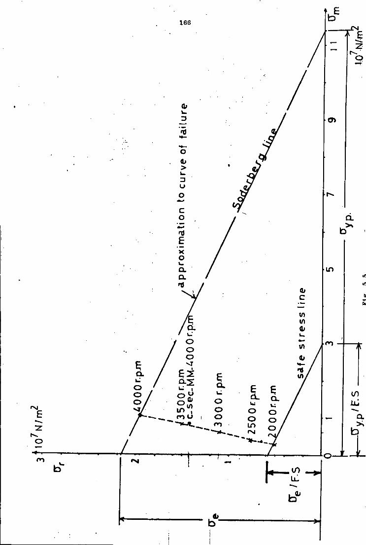

167 I
| F 1 (b.excess c learance
I
^1
7
/ I
/ I
ink shape
F i g . 5 . r
M
71 F i g . 5.7
c .s ingle or double. pin deformation
168
5.9 General C o n s i d e r a t i o n s
During the a c t u a l weaving operation the s t r e s s e s would i n c r e a s e due to
the e x t e r n a l r e s i s t a n c e introduced by the threads on the combs and needle
arms. The va l u e of t h i s expected i n c r e a s e i s unknown. The hardness and
t e n s i l e t e s t s performed on the connecting rods showed th a t t h e r e i s a
d i f f e r e n c e between m a t e r i a l p r o p e r t i e s of the two l i n k s although they were
expected to be the same (phosphor bronze a l l o y ) . Mechanical damage ( s c r a t c h e s
i n s i d e the l i n k bores and fl a n g e s i d e s ) i s detected on both l i n k s . The
e f f e c t of f r i c t i o n has completely been ne g l e c t e d i n the a n a l y t i c a l c a l c u l
a t i o n s . S t r e s s waveform p a t t e r n i s complex i n s t r u c t u r e f o r both l i n k s and
i s very d e s t r u c t i v e i n nature from a - f a t i g u e point of view.

169
Chapter 6 - Conclusion
Bending s t r e s s e s i n a d i r e c t i o n normal to the plane of the mechanism
a r e present i n both of the l i n k s i n v e s t i g a t e d and have a dominating e f f e c t .
The a x i a l c y c l i c and peak to peak s t r e s s v a r i a t i o n i n both l i n k s i s g e n e r a l l y
i n good agreement w i t h the c a l c u l a t e d v a l u e s . The bending s t r e s s e s normal
to the plane of the mechanism a r e due to misalignment e f f e c t s which a r e
e x t e r n a l to the connecting rods themselves. The dominating c h a r a c t e r i s t i c
of the dynamic bending s t r e s s e s has been confirmed w i t h s t a t i c t e s t s
c a r r i e d out on the mechanism. Even by n e g l e c t i n g the bending s t r e s s e f f e c t s
on the l i n k s the present design i s found to be u n s a t i s f a c t o r y a t a crank
speed o f 4000 r.p.m. s i n c e the a x i a l s t r e s s v a l u e s a r e above the working
a x i a l s t r e s s l i n e approximated by the Soderberg c r i t e r i a . I n the presence
of bending s t r e s s e s f a t i g u e f a i l u r e can be expected to occur a t approximately
2000 r.p.m. However i f bending s t r e s s e s a r e n e g l i g i b l e the present design
can be used up to a crank speed of 2500 r.p.m. (See Appendix A3)
To i n c r e a s e the speed of the mechanism the f o l l o w i n g general b a s i c
major p o i n t s a r e suggested:
1. A d e t a i l e d d e f l e c t i o n t o l e r a n c e and c l e a r a n c e a n a l y s i s to reduce
the bending s t r e s s e s due to misalignments t h e o r e t i c a l l y to zero
which would a u t o m a t i c a l l y i n c r e a s e the crank speed range up to
2500 r.p.m.
2. F a t i g u e t e s t s on the l i n k s to determine the experimental endurance
s t r e n g t h .
3. The s t r e s s c o n s t r a i n t s a r e determined. Any i n c r e a s e i n the c r i t i c a l
c r o s s s e c t i o n s of the connecting rods w i l l decrease the s t r e s s e s , and
t h e r e f o r e would y i e l d a higher o p e r a t i n g speed.
4. I t was found t h a t extreme, a x i a l s t r e s s e s i n a complete c y l e of
input crank r o a t a t i o n o ccurs a t d i f f e r e n t a n g les of input crank
170
r o t a t i o n f o r the two connecting rods. Any s l i g h t changes i n
l i n k l e n g t h s and geometry to decrease the extreme angular
a c c e l e r a t i o n v a l u e s f o r l i n k s 4 and 6 w i l l a c c o r d i n g l y decrease
the a x i a l s t r e s s e s on the two connecting rods and change the
c y c l i c a x i a l s t r e s s p a t t e r n .
Without changing the c o n f i g u r a t i o n of the mechanism, any
s u i t a b l e m a t e r i a l change w i t h a higher endurance and y i e l d point
l i m i t w i l l a c c o r d i n g l y permit an i n c r e a s e i n the crank speed.

171
Appendix A - l
<
LL! U l o
Li.I
L i . C ! i/i
CT-
CO —
_ ) LU
< LLl
< ^
tn u~, j ; |
LlJ
a: LL. h - o t o
• c3
a. LiJ U ; r_3 C i c £ c LL.
s < CJ — r f 1—
c;
LU LL O
— I-U ^ _ l > -
—*;
U.I 5 —-1 — t o Ll-! CC _ J < LU Cu. O
— O LiJ I K u t o
CJ
I—!
^ - ^ , •.,
CM ra
CD CM
CM CO
C3 00
I 1-1 —
; > II r-~, < a UJ
> o
H M A « i .n L D r ~ OC DO OO C H H r i H H H H H r i H H H H r - . ' N C M CM CM C-! r
t—! -—
• r a : o i-H CM i—i CM CM
/ \ / \ ^ / \ / \ /"\ / X
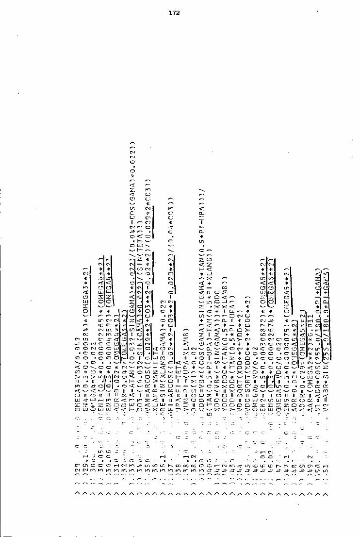
172
C-l
r - i
o • o *
to
c o
I C J
o •):
<M
c; o
o < o • \ — v
O LlJ
-»w» I— *— CM
O
* Cu. *
-—• r~ a: + C3
c c J; * <r 2 1 C i l d
* * cs (7) rsi * h - < * 1*—s ^ —
c i * C * _! * C-J •=3 * • • c ; X
•< »—* o + < * < r-o co C5 C. [ • — CO a t q
< LiJ LlJ C Cv] < n O UJ UJ <r. + + 1 CD < c * 1 CD * C) « ? • •—• ^—. C! — —
LU o O * C J C4 LTl Q C4 0 c5 I x l 0. c
T" V — CSI * • X < * * •!!
O • I : »•—• a + O * — ' + + CL, . * * * O V - ' - »-—• CS o • r-~-. t o — ZZ- C J C j .—V C J •
• i . LTi C-J cs # 27* + O + C_ f * O CJ * • } : «-l O ^ — . I C cr * — CSi * * — * O I- - •H i C 1 0 0
CJ in •Si t-' LO <: * + -•— 1- < ir, a. O > - 00 i r ; L n + Lr, i
ex; C-J < 1 * <; CS! CO 1 O + t o C J c - <r f 3 - v . C I L n cr- < CD C I » — ' * •J." —* <" > - CM 0 CJ 0 IS. C3 1* 1 °
C C J tc c CD (.1.1 r-O CSI * <r d o - • + * f O 0 CS! cr < UJ • 1 * c v C J o C5 U.l O — O <-r c3 C J _ j Q! C I * CSJ 0 0 CD ••>• C « LT, ILT!
t o o O T o • t'J • h- 1 o t o _J * 0 0 0 0 • 0 L i ! b •k U1 O o • o o c5 I c : LU CO • + • o i — h - r=r. * 0 • c 0 ~ ' * C ! Bcs! — • • « S—' '* CSI V ' h- " ~ < < CJ — t o <r a o 0 • * « O * C J v '
< c o a * cs » — ' r r , •- + 1 - c * i •): 1- a x cr. CJ C: < t o t o * * CM O t o _ l LL! •K V — ' C J - w x «- • * 0 * •H CS! CD 0 • —
7> JLO CJ • O to 1- ~ * LTl + O * w 1-. LTll ' • n l > C l O UJ CO II • II • • • 1- C C.5 > N ' c [ ( X • C : Q II •I II • 0 • T" * •it
f-n er; o • < «. • II — — •fc - > X O t o e=, i n • O O or. CrJ s—• II II < EL! — LL. t o l l II X o - </) < •*«--• 0 II >— • |-Q
l~> II o II II II cs. < i l II t o < II II b o II O II t o II II II c5 II 11 Q' II U ! -i- LiJ i-H m I ' <; II II o CD <-r- o C i C l II O LlJ C J UJ i .n G: C.5 c c if II
* - ST !Z! LL! c < _ J LU — II O 1- Q O O Cl CJ ^7 -~ a O
IJ-I O L:j •_ c._> X LL. — • >- o ' ' X > :>- : > > • O LIJ L i J O LU <T '• - ~i c -'.1 t o 'J"
- --• "1 " .
I A t£> - - - ' ' - - - - - ? i - i C l
1—t J 0 C l - l t—i CS! C- I - I z
• • • _". _: • - • • cz- t~ " or • • • *
c c: 0 1—1 C ! L n I C i i f : CO 00 CO ^0 i—> r J Lt- L U t<:> r- c"; cr. 0 1—1 C J C J 10 N-i hO N-l m t-n - • - -d- ^ j - •4- -Jb J " LO U S
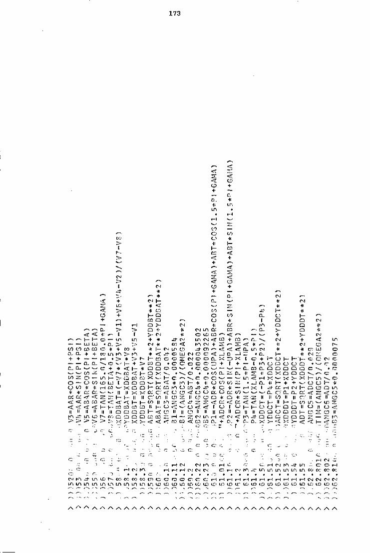
173
+
o. •): i n
C"' +
* i n
I
t o — 6 co o * * r -
I — CD. Cl < < + + —•
^7> < • I C-! +
* + — — * — a .
+ CJ j — * <
CL *—'
L'.J CJ j — * <
< * t o —
+ 1 - Q o t o + c a a o *
— i H r - ! o >- * f—v /—. D - y> + CvJ a: < < * 1 t CJ o c a t—^ <
r—- t - h- — LP. m + * J- CV.' i n r - j c a + — LU UJ • CJ * Ch'J < + ^_ 00 t o CD CO <~ * + CO + * 1 - j - <s < a. CL + + CO LA m * < c LU o o <: 1
+ + — — r - l • ^> * ^;. 1 - CO C o o D.. — — CL 1 - '+ C l • o c o o o •—^ + ( a. N V - + * < \— * C2 C j • C : o — >—- t o • CC r- i >•: • • • t o CI. to o •— LTi !~~ £li CO X \ o o >—• —
o — o CO CO L J " l Q C3 C ! r— <^ * f - i I - - * •»: o V} t o CJ t o 1: r H CO * - x C j O -t— Ct CG o * c *
* a : cr. II II X x D: C: o o o O tx. o < r < r II it 00 II C5 ~>~ n a * a
<: < rrt < < . < h - h - t o II l O Z: ' < r 2 ; <z <r <; < < r r£ ca II 1 - O < r ' o < r o l "
II II' II n ii II Q CJ / • ^ h - c~ II II o II n II C J II K"' LP, t o O'J CJ O C3 co i H — Lr, i—i <f C--J ~"' 2* ^ » --' > • >- < < r CO < in 0 . +" D .
^—*
C3
+
^T. D . •»: S
C l
* C I
. + * a . DC
DT
C J a Q
a. + YD
* CV
r ^ + < * •I: C J o LTi * * cr. LU o • D . 1— C-l I;' o
+ 1 - C J 1 - C c; C -( Cj f'~l c.;-C_> O •
CO a. O o Q Q Q *— • ^~ l : tZ! X O O Q r—- m
X »— X >- X h - i n o . • CL • I : h - + + ^ • CJ V- •is X 1 .71-cs: CM 1 - CJ CD o
v^- C - o' D_ a . C i «r < C J II II CO II II C:' II < II o
< h - 1- - II H l - t o LT. V ^
1 - c :-o t~ Q II o II o <• II Q C l o O C i h - ll"
Q CJ C ! Q C i —- t-~-. a . X >- >- 1 -
r H CJ K 1 . J - i n CJ o
••j i — ! C J r - i 1—•- r - i c ; CM C J c t—f C J K' . i n W: m i n LP, i n CC oc-
C-J m l O r--- CO CC or? CC O o O c cr. c- i—I r-H l-H i—1 l - ^ t—1 x~\ r-i r-t I—1 r-H C J CM C l m m i n LO m u-\ i n i n i n m LT. l£J t c I D i c ID t o IT; IT' ID I E I D (D LO IfJ l O i n ITJ I D LO
*— --- - — . — - e—. — . ----- -- . —
-- — -—\

174
CO
t/3 <r o _ J
<• * a. CJ —
*— ^ > — • © en CM •
* * — © <r m * + ~ LC- I D r. + _J
cc <! m CJ C.3 CJ * *—• X LTi CD < < f CD CD CD CD en *—- _ j ©• L L l CD c i : ~: 7z Z • © LL> U.! < CM C-I V
•—\ o 2! LT, * * * »^. i CO C-J © * O O cn J - en. CO CO — o * o c i * • LO r ~ L n IT, < < < < c D: /•— CJ.
r~- . * c O •»: * r-~. C-: C CD CD CD CD o * Cr.- * i n tr> o : 1— •*: CD J " LT. i n m LA en r-- LTl ID LU UJ LU U l * C-J © . C-J CC- hn. CO r- c v CM cr-- c- cr. r-- C I CTi \ " • © CM o CM ci- < < LT c < < < < N <N m r~- r-- m r-- c o o o CO i-H • ©
© o + CD •it o © CD CD CD i ^ - • r - en r-- r-- c- r-- r-- * * •is * © • o C CM UJ Ln © IJJ IjLi LU LU L n L n ui in L n LT. i n C-I C>4 ^ > CO r—. C I i n r 5
© © O 2! r» . © © > * > C ' LPi cr- • c en • c> CT! CD O r-- <r o m * c © * O o © © C O O o CM + CM CM OJ LTi CC CD CD *—' • i c CO t >•-.' • a a: © • • • • • • • • C-l m c o CS' L L l CD ©• * en CD
c: o © ca e c Ln CD r-- > * * r-- CD —•• c C-J v . - CO L L j i n
* •i-- * < o c •ft * < < < < in i n < m i n o © r n © IX. o LO CO © L L " > L T ! CD LD *»_' CD © o (5 CD * * l - +: * * * o o © © * • • 1 + o O o h - T2! • • • LlJ UJ i.U U ! — >=: U-l < l < o c o © + c:: + © c N ' i-n CD CD CD CC <t © © " ~ ? " to II ID in Q. <r U-l 1 - o © U) i - »— ( II CO
Cf II II II II O o c o fi II TJ CJ II tv! L!J • • • • II II >< II II >-< CO C-i m II II II l i l l II <c II II II 11 © o o © II II »—- II r H CM cv'j t n II
>-li II l i " II c- i h n — h - < -J • ~ < r II II II II .oc II cr m ; r CC. c c — — — — H - h - r - H </:• _J LU CL. <t LU h - l - l C-! t A
^ > L u C l 1— O O LL d i n CC CO < Q- a. c c LX o„ X > - LO ~ . CD l.'-i < < << I-" tn J_ U-
."~ c i •• i J : c: c . ,7.' Ml '.: C- C" • • -
c : -• ( T — .-. - j — -cr J • ... - -
C c •,7 z. c 12 -- .1- -. •-c V 7. - ©
.71. c i t~~. c 1 C © -17 I - © © C.T •* — -'S l-H C-J J " m i - H CM *- i n CCi
CM |J-. © i—i i l l" i - l r-- ": r7 •111 - ' m m i n m m i n U"' m i n m ir. m i n CC- OCl CO m r-~ o l C> G" cr. T-t I—' C-J rn K i r o i n R-i O l O l C7> CT. © C i C :
CM CM CM K l K ' t*-. K\ i o N"> i n LO CO CO CO 0 0 CO CO CO CO K ; CO CO 0 0 CO CO oc OT: CO LC I D LC ID IC CD ID CO LC CO CO LC LO cc' CD CD LC' CC CO CO Cfi CD CO LfJ ct: CC' CD CD I D
4 t - • L r-~'- -— *— • -• .- ^ • ^ ,
- —. - ,~. 1"N —
A A A A A A A A A A A A A A A A A A A A A A A A A A A A A A A A A A

175
i n
ci s
i n •
CJ 1-1 L L ,
*—. C l CN H
* li., • o
I D a " •
* II r - LTi co cc ' •
'—. or U J >. i n
< r— LU + • • • i LO v CJ
X O + Z i—i a /•—* LU CS CJ L L
CO l l - l + N s o a C l — CJ * * • II
* t o CJ * LU > I D CTl J - LO + U . CN m • 0": < — O c I D • CO -
• CJ •is -It' L U II X c < CO t - l Cv! i n + — C l
o c CO * m err t o U i o LU • T7" CO i n
—• c cr. CO LC U . I ft. — • d • 1— * r - l T N CJ
LO * o 00 i— CO * i-H C l l-H c %— CO m K C-' LL U.) .J.. + LU II •—- II I x l 0'J U.I CD
CM C CO II LU cr: II v_- 1 - — II CC II 00 r n ZJ 1 - h - r— U.J <: II — •
>" II i H LLI 00 C> CO CO O I — o 1 - O -LC cr a: II li l ~ — c; o o LT. LL] O 1 - l - c un cc: o ^ . O J— U . O'CL co t o (— L L LL LU LL t/J LU
: V - "J •J-
- CJ 1-1 o , - r_- -
-CJ f ' m LC
LP. r-- co cr- r i i O CT: O CTl en C l O i C i IT: c - - • -
00 CO 0C> CO o o CO CO or. CO C D C-i t n — i LP I T L C LO l.o I D LO i c LD LO r - . r-- r~-
1— #•--. —- ^- * .»•-• --• ----- ^ • ^ '--
' " -
/ \ / \ / N / \ / \

176
r-I l - l l £ ! © i C 00 I T . c LC r - l © • O CM r H m © r-» r r CC r n © i oc r-- o cc- LCV i n J - r H LTi CM LO © CM LA LCD O ! r-~ cr. i n r-- r - l r~. O ! CO -=>- I D r - l t o I D r ~ i «rj* CM c r - l r n CM L!"'. CM CP. cr CM CT r-.1 OJ CO J - J - - t CTl r - r n C " r - l r H © © • r - l © © • i n m © • i n I C LfJ © O l CM K CM CM m o r-n CM r - . r H r H K-, CM CM r H r H i n r H cc L/1 r H CM
r-1 C © r—1 C-3 CM CM f—1 i - l © © ° O © © © o °. © r H r H CM CM CM r H
II II I I I I I I II II 1! II II I I II I I ll II ll I I I I II II I I II II I I II o O o o P O O C-J C J CS a D O CJ o C i > > - J > > ;> ^ > ~* > ;> --' > • >
© K . i>- LTi O ' LTi OJ I V l —'• r-~ LO Lf\ oc LO c:. i n © LO r H m r - l CR (T! © cr. m LP. © m LTi CO © j - c - IC- 00 © cr- r-H I D . r r o r CT, ©• o o o C ! CO m © r-- r-- NT m CTi LO r H LO cr N " . c n cr K i -•J I D r - i CC' C" I D CP r - . r-1 © I — ' o ; CJ I D o;. iV". CM C i c r LO u: CM t n O H LTi © -•i- C-3 C l CM i .n r-- O LO i-H I C © -3" r~- r - . r--
II II I I I I I I I I 1! l l l l II 11 II II II l l II I I I I II l l l l II I I l l I I C J O o o o CJ 1 C J o CV CJ- o C J o C J C> C J C.5 c : C": C J
p D Q o CI C , a p O C J o p c C : O Q C : C l O
•i ^ • > :~- > > ^»
r H C J • T i ' CO LD r - i i n ir\ r n r - ~ . r H c n K \ © © LQ cr. O l © O l CO C D i n CTJ LO C I 00 O l i n LC O i L C CT! i n o C7! t n m o c r n o o © i - H I ^ - r H I C © LO r H r - i O j LT, I D o L C r n O l LD r-~ © © t - - r-- © r H m m ©> r H C c r tr\ Oj r H CO r H m OC! o i-H r H
c M r ~ i n cxi Lp c n c r c n LD CM L - \ © LO CM LO © r n cr; © O l r n
r H o © O l O l O l CM O i CM o : r H © © r - < l — ! O j O i OJ CM i>n c-; r H
— .—
II II II II II l l l l II II II l l II II l i II II II II II II II II II l l II CO co CD on ce [JC: CO nrs tic- •r.c DO £J1
^- * - > < r > ^> cr ~~~c
© r H CO o : © OJ O l C-J © O ! CO C-I o? r H 1—1 O 1 r H r n O J C l C J © i n r n o o © f—I r-» C J o - c~. © © i n c n r-- © r H - r f cc- r H m C OT.TH r H o i r-- J - C--' OJ LO © ! © C-l: i n Li", IT, lO l-H c © L,^ ©
I-. O l r n OCi © r H i n © LTi r - l rH c- CO m LC LO C J r H r H • i i ' O ! ©.LT, m r H r H r"i © : i n r-.~ 0C' CM o ; © . r - . m LT, LTi i—; C J
OJ OJ o . : rH r H © © O o © r H C J c m m c CM r H © ©. r - l O ! r n — —-
—- — - . — .—. - 'V •- — -—• '— .-- CTJ
-• - - • - L!.l . - '—: -'-^ - . | . . _
II II II II II II II II II II II II II II II l l II II II l l II II II II l l < LO •rf * t <; < <: <f <r <T <^ < < • » ^ < c5 f CJ C 3 m CQ r.6 L i : r j ira CD — ^. > ^> J * rr> J * r^- T> 7> LJ "- tir E LU r- _ UJ K ! © © © © © © © C ©* c: o © © © © © © © © r -
© © c © © o CT- O © o © cr; © rr : o o © © © © o ©
O © i .n © i n © i n © m © Ln © L n c r m © u-\ © m © m © i n © i n © . - - O — r H i -n CO © O l LTi LO oc c n r H o - i n r-- q r H m LO —
— r - ! rH r H rH r H r H rH O i C-J C-J O i C J CM i-n' r n r n 1-1 H ZZJ II l l l l I! II l l II II II II II II II l l II II II II II II l l II ll II II —*•
o C C l L U CO LO C O oo t o CO CO t o CO in t o t o t o t o CO t o CO t o t o L ' ) Ln t o V< CO h - LU
c . a . CJ. Q . a . IX £5.. r i CL a Q. 0.. 0 . G . CL. Q- D_ n . f i \.\- CL. t o X L J -• U-.i
— • - • - 1 1 :
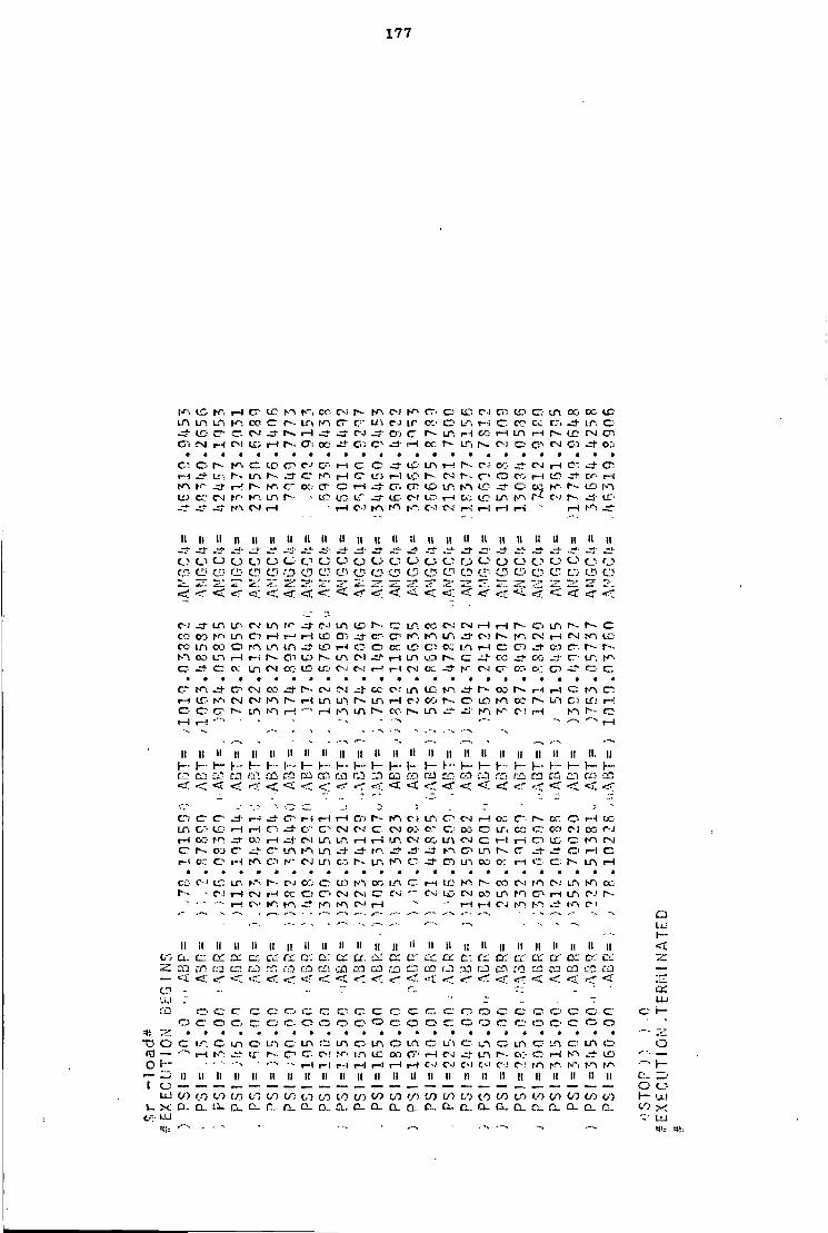
177
t-r; l £ H C" L C tr, CC- CM l-P. LTl LP1, LP, l-P. CO c r r-- i n i>n G~ c m
©I CM r - f CM in r - l r>. (X: OC -=t C l © •
C-J pn cr- o t c CJ Ci o c i n os co i c C J IP : CO ©• LP, r - i C - CO « CT: .3- i r , © c n c f - m I-H c o H i n H N t c M c n J - i — i oc r-- m c-t o c i CM C i J - or;
c - © \.— CO cr- C-' G-- l-H c r O LP i n I - i c< OC- C-J i—t C" CT-1—1 L:-. i n r--. © m | H © LD LC r-- c-; ^- c > o c:. l -H LD r-i h n t p I—-' r-p. © cr f—i © cr. co i n LC c °? I D i>n LO CC.' C-J rn t-n i n r-- LD LD LT CD C-I LC i— i ec LD m r-c CM J " LC'
m CM r H r-H c-; m CM Ci 1 l - l i-H i—i I - I r n
II M II 11 II II II II II II II 1! ii II II II 11 11 II II u II II II II -"Li" -A - j - - i -
o CJ o t; CJ c_ CJ C_1 o O CJ cs o O o C."1 o CD rj> CD CD CD CD CD CD o CD CD CD CD C 5 CD CD CD cr CD CD CD CD CD C 5 r. .~. " i : —i* Z_ 7--" -•'*
< <r~ <£ <- *— < < < < <? < < <£ ETC < *r? <; < <r < <;
C-J j - LTi LP- C\' i n TP C-j i n CO LP: CO C-J CJ »—1 i-H r-- o i n C CO |-P\ i n G": r - l r - ! i-H CD en J - cc- © - r n LP: -ZJ" CM m CM r—i CI LO CO 1/1 C O o r n m m - I t CD I - I O e cc. I D Ci m !~ l c ; a J - CS1! c r~- r--r-n OCi l_n i-H C l CD m CI I - I i n LO I-- c : CO OC - i - LT. © C o: m CM OC- LD LO CJ C-! r H r - i CM OC LT' o : c n ^1- cr>
c- G-- C 4 CO r-- CM CM J - CO C J Lfk LC f^- oo r ~ l - t i - t © r n © i—i LC- C J CM i>n i - l L n LP. r - m i-H C-i o o o LO m CC i n LO i—; o o r r i n t-n i-H r-H i n CC- i n r n C ! i-H ho r-- © i-H I - I - '" - —. l-H
• - - • _ ^ -'^ -- •— -. .—. —
II II II II II II li II II II II II II II II II II II II II II II II II. II i— \~ 1 - i - h - h - 1 - f— r - !-• I - h - 1 - \— 1 - h- (_. H- \~ L... h- H- \—
CL: ire ca Cf! CQ CO CO r J CiTi CO CO co CC5 < < <• < < < r < • <t <r <r; < < < *_<
Ci c r c r •—> L~ r--i r—1 l-H cr> -)
m C i LP: c r CM i-H oc C" r - CC © r - i <K LPi G" LD i H i—l o G- C' ' CM CM cr CN 0 0 c-- o oo © LTi cr; c r CO c i OC C-J I-H C O t-P, -=r i—! - j - C-I LP, LP. i-H i—i LPi CM CO L.n CM C l - t i—i C I LC cr: r n C J c r r-- DO C " C v m s n m - • t — t n J - i>p. c r m r-- c St O l-H C r - i cr; O l-H m t-p C-J i n CO i n o c~. m oo o : t-H © © i n l-H
CO C-J L O LT. t--- C J © CD OG m © i-H I D o o CM C-J m hP, CC-r-- C J I -H C-J r-H OC © ©. C J CM c r C^i C- i i r . ' CM CO i n t-n © I—l i n C ! r -
• ~ - l — ! C V rP . l-p. I-P. m C - ! l-H l-H l - l C J m I P : - J " m C i •-- — - . • f— - ' Q
" - • r*—. •- • — -- - I U L ll il n II II II II II II II II II ll tl II II II II II ll II II ll II ll 1
< i / : . a : © o r cx © CL-; r e D: a : CC. p i J c c CI' CC CL\ en CC c r Dl ' CI" CC c ; CC riir (SJt C7: co CC CD. CL: ca ca CD CO CD :XI cq CC) i.C 1 CO CO co <-p CO —
— - < < < T «:. _ < <- <<; crl < • CD Li 1
- - - iz2 L U
en. © rz c : o © r r © © tz O ©• cv © o © © © • © o © © i— o © © © cn © © © © • © © © o o © © o © © • o © © © ©
o cr IC-. © i n © cr_ i n ir m © • LPi o m © L f l © m © LP, ©• Ln © m © 3 — i—i i - - © © C - ! TP* m L C oo G " i -H C-J m r-- CO cr r H r n L D —
i~ • " - r - l I - I r H r - l r-1 l-H l-H C - I C J CM C J c ; r n hP t-n f p r -117; II II 1! II II ll n II ll II II II II II II II II ll II 1! II II II II II C:_ ^.' CJ O CJ UJ C/J CO CO in CO CO 0 0 0 0 CO to 0 0 CO 0 0 V ) oo 0 0 0 ' ) CO oo OO t o 0 0 in OO t o h - U l X D - a. L l . 0- r._ o . Q . a . CL. CL Q_ C . Ci, D - G . D_ p_ 0 _ C L 0 - co
t--: 1JJ - LU

178
CJ i n 0.1 CO CC r H CD i n 0"i L O CJ LP, ^+ r - . r-H r n CD m CC m t—i I D CO r-4 C l CTi CJ CJ O CO C? C-J —j ot c r r-- r-- m CO i n c K-i ^+ C T •—i LTi CJ Cr. r-~ CZ. . s - IX.- ! -n t - i CTl c~. en r-- i—i CD CO LPi t-P m CM r-- r - ! t n IE c c r - . o r r n OC oo o CO -rJ- r . CC, o I-P r H t > ; r p i n CO C C I f ! r - I D c . CZ i n - i c I D CO c i I D - o r-H —J r H r H
CJ -zi' I D r H ir. o LP, LT'i c c n C-J 1- i n r-- CC m <r I D C D in- r - l m r>- c l—i r - l CO i n CJ r - l r H CJ L A C-J C J o
t- i r H i H r - i i—!
II II II II II II II II II li II II II II II II II II li II II II II II ll i i . ; c c I D L C LC ' L C ic> i n I D L D I D I D L O L T L D L C L O I D I D L D I D L C L D
< < < <: < < < < < < <r < < < < < < r < < < • < < < < CD CD CD en C ' CD CJ? CD CD O CD CD O CD CD CD CD CD CD CD CD CD CD CD C3 L U L U L U LL) UJ L i J L i J UJ L U L U UJ UJ L i J UJ L U U.I L U L U L D L U LU L U L U UJ L J
O O c o o c o o o O o o C C o o O O O o C O C)
c r r n LC:- CM C J i n i n pp. r-- L C LC! r-» C l C-l C J r H r n O C - O LS; C J c n K \ c c~ c : c r m r-- cn fi o o r - l t-Ti LC- CO er> cr- C I r-- C l CXi C i r H r H O o: CO i n o> C l c i—i r>. C J l-P. L D L O i n CT: o n>. r - . un c o C ! C J C J C J •—i CO C J j - m uo r n C m r H C J r H r-4 r - L D CO C J r H i n L O I D C l
CO u-> L'"l tf' C c - c - r H r H O o o O i C J L D cr m r H J - ce O-
i—i r~: LTi r-- r H m C CV' r^. I f CM L I H N"i C L D O N"i N - 1. L D LT> O C J r H r - i i-H t>n LC co c~- c : c n r - m c i c - m r~- en c-i c^. LO r - i
r-i
II II II II M II H II II II II II M II II II II II II II II II II II II m m i n i r I T , m LT, m m i n m i n I T . LT. L O m i r , LTi iS i n LTl LTi <r < < <: < < <t < < < < «rr < < < < < < <r < • < < < < • o CD CD o CD CD CD CD O CD CD CD. CD CD CD d CD CD CD CD CD o CD o L U U J L U L U L U L U L U U.1 L u L U L U U J U J U J L u L U U ! U ! L L ' U J L L l L U U J L U U J
o o O c O C O C O C O o O O d c- d O d d O d o c
c r cr. L C CT' o-j CT! CO r ' CO L D C-J r-- r H OO m t n oo o c CM i n r^. CO CJ-I cz- L C CV! i n I T . L C r~-C T ! c r r--! t—i CT- m c - N-> IT- m j$ C J c -
CM c n C J c cc. U ' l C J c OC O - L O u-i co CM _-t- m C i n . 2 - i n C J O ? r^i r n L O i n C J r C CM r C oo K-l j - C T C ! rn i n cr.- rv . L D I T . m cr. O j LTi ^ j - K l - C J CO C J C ! CO OC' C*J <7: f i C J r H cr ^* O j LC' CO r H m
C " r H j + C l o c : r--! L D r H cr. l—i r H i n _ ^ C J C O C I L D 11". r n r - o C J K . C l o r ~ - i n m r-- en o C J m m CM c m
r H r - i r H l - l r H r H r - l r H r H r H l-H r H r—l
II II II II II II II II II II II II II II II II II II II II II n II II II —u - -•- m=i-
< < r < < < < < <! < < < < < < < < < < < < j <T
CD CD CD CD o CD CD CD CD CD CD CD CD O CD o CD CD CD O CD CD CD d U J U J U J LL! U J U J U J U J U J U J L U L U U J U J L U L U L U L U L U L U U J U J L U L U U !
O O O 6 o c o 5 O O o O C O O O o O O c 5 O C 5 c
r-- r H co CJ c~ i - ! o c - o C-J o r-H LD r - c o c j co f~- i r , N c H r - r > N H O ] I C I f i H K : C H L C H l^i C J O U*-, H O j h H C J C:~ t^< L O r--
CM ^ i - r-~ hr- ID u-i O L C O m LT. L O r H r H r n N". O l r - l U 1 C M C -tt" LTl r H JTT i n C - m LC- LP. O i t^. 17"! r H f J - C~ OC. c r - ; r CT c r LC:> t>- LP, r H C"" C m L D l-P C i P~ CO C T IT, c C J CD L D C J C-J r H l-P. C J L C C J r - r-H r - l
r~ <r c r or r - cc> c r H c-i r-- r H co i n p i n r - H C> «H O-J CO ID C-T r-- i> L C J^- hn c i r - i r - i • c i N-i LTI iT.i r - r~ r - i n r H w i ipi r-- r--
II II II II II II II H II II I II II " II II II II II II II II II K~. f-P K rP. N": K 7 m K N - h~ h-P m l-O |P rPi K ' , K > N^. fP . r P | P . | P i m < ; < < < < < r < < r < ; L < < < r < < < < < < < < < < < < < CD CD O CD CD O d O CD CD CD O O CD d CD CD CD CD CD1 CD CD CD CD CD
CO LU LU U i U - U-i LU U J LU CU L u U J U J LU •— U J U ! U J U j LU LL l Li.I LU U J LL! U J
— o d o o o o o o o o C l .-. _ . . r LU L " .- - - . ; ; .
co c c c c c c o c - o c c : c r o cr. c c : c o cr. er o cr o c c o o o o o o c o c;: r r c - r r o c : o c - o o o c c ; c ; o o
•«=:£.• "C O o LP, er- LP. cr. in, c i n <r.- i r , cr. i r , C. u~r c m o i n LTI O i n cr i n o ro r-i m -3 t c r-- c r c r CJ t n LT-. LD oc. c i r-i c i j - i r ; N » c H r j f ID O r - ' "• "* ' ' "• | H l—! r H r H r - l r H I—I C J C J C o C I C I C - ! r-P r P r P t-p r n
•— r~j II n II n II II II II II II II II II II II II II II II II II II II II II ( CJ
LU CO CO CO (/) CO 00 CO 00 0 0 CO CO O'J 0 0 CO W) 00 0 0 CO CO C O to 00 CO CO CO i - x o. D- L L c a . D_ CL. c\. CL c . CL a . ex. c . u . Q. CL. CL. a . D. C_ t x c_ n . a .
• L P . L U
L U
r -
UJ = I -
o
a . rD o t o r - L U 00 X
:• U.I
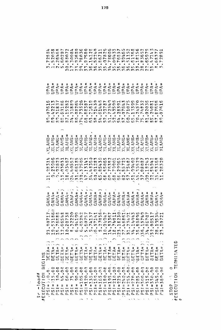
179
J+ 00 K is N jf C C C K C H U5 O fA N CO IX) f"! C N H co Ln t o en I-- oo co IA c c c - -—) csi © IA IA t o i n u r LT>. r~- t~. en K C M C O B C IT; 1-3 CSI M S O J 0 i - i r - ! LQ C l r H I". OO N N i c c K c n oc r s J - c - i ic is. ca c ^ o H H c o 10 L", N CO CJ I S LT, C-J I E OO I A C : I-- CT> r - I LTi CO © - | s © | s | A IT. LC5 r H CC I D LCi I-- ,
IA -—I C-J i n c G" f . IT) i c IT. i n J - m i n LD ID i n IA cc- CJ i n c c I-A I - I I-H o r - : M w c . c . M r IA IA IA IA IA IA rvi c s i r-i
II II II II II II II II II II II II II II II II II II II II II II II II II < <s < < < <r < < <r <r <r <r < < < < <x < < < < c. D. o D . a D. CL o. t i ' a. c. cT a. D.. CI. a. CL CJJ c. a. a .
13 — 1 1 13 ro I'D ZZT" _-• ro ••—•4 13 " 3 i j _ 1 ID - ; '—i •"3
t o IA I S L O Csi cr | s CT: cn CCi | s c r L C r H 1 , i n CT: C C J ID- r - i LC- L D r H I - I f A CO CO oc. L D Csl CO r H r A oo -r}- C"< O " ^ j - r s c n I-- I A I A oo L r . r H I D est 00 i—1 Csl c c C J m I A I D —. r - LT, L A | A , LC- o I A LTl CO C - L C LT-r - Csl r H cr. i n 1—1 cc. hO CO r H r - l r H O") C J I A CO | s r H r-A j + CSi i s I s
c- -=!• I A L D r H I A o | s 0 3 C-J K i I D | A | s C l c | s f~l C J c - O C l o:> ©
<r c - c - co r - _ -»- G CO | A cc. Cs- H C ! | s O i n LT, i—l i n ^ - trce CD CO CO co C j CC i s L D L C i n m i r , LT. L O L A LTi L D I D | s - r - c:- CO o: ee
ll II II II ll II II II II II ll ll ll II II II II II II II II II II II II CO CO c a co c a CO CC! CO CO CO co CO co co CO co CO co co co CO
-T_ < <-r < < -»*•?* <r < < Of <; <; < < • < <51 < < _ 1 _ j _ J _ . i _ l 1 i _ . I _ j _ i _ i ^ i _! -1 H
x x ' K >; * : < 5< > ' X :•< X X X X X X X
I D IA r - i r s C-J m LT'i r—i <—> I A G1 L A CSi I--I i o L A r s C-i c-- I S r A r - i oc. © I - I © csi | A CO i n o J - 00 r A C D o I D Csl CO o C ! CO - S i ' L O C-J
IA C S t o © i n r H IT: r H C i J - O K". cr. C " . | s _-t- i n C- l i n | A I A oo I A cs; | A r A © L O i s | A , CO r H m LTi ir tr< CT. m L A c L A oo o.- | A . CO c v CSI C - ' cr c
-=•" L C ; I A CT: cc- or i s | s . C J LT, t~ C"! I—! m c - C i
r H c-, c~< r A C C ! - ! CJi | s LT, c c c r CC; L D C J r - J W. I S O C I L A l-H ! - ) r H r H C-J I A LT, L.Q L D L O L D L D CO I D m L", *— - r A NT C l r - ! r H
•—-.
II II II II II ll II II II II II II II II II II II ll II II II II II II II
< •sr »_-r ' -4 . <J. < <; < < <; < < < r < < < < r < *~ ---- •cr-
< <? < <C < < < r 5- < <r <! < < < r < <r. < »-r CD CD '3 CD CD CD i CD CD o CD CD CD d CD CD CD CD CD CD CD o CD O CD
i s I D CO 00 oo C J i s | s r - 1 L D r-- r H C r H r - l I A L D Cr, r s ^- r H i - ( OO CO r n CSI cr. m |Ai L£J r H I A L D C". c r J - a .—i r o C- l | s . 1—I i n I s CSI r H C I i s r H i - l C I A O C I o:) CO r - . i s L A L f \ I S o I A I C I D © C J J - r-- r-- r A CO L D r A ^+ I C L A C O CO cr- O O" m r - L D CM K i c?- cr LfJ r- m C- l C f ; LTi r - r - l J - C i i—i 00 t - l C f-: CO
IA CT) LTs Csi a CO L D IC m i n CO o J- oo r A ^- r - l -4. IT; L C C i CC- N". CSI i-H r H i - l r H r H I—1 r H C J C J I A |A- | A | J - , t-n I A C ! C j
y— . ' - r—.
- — • •• •-. CO • - — --• /—1 --- - - ^ L U
II II II II n II II II II ll II n II II II II II II II ll II II II II II l ~
< «r <r < <rr «r «3 - <r < < < <r •=:r < -eJ" <r <: <r 1- r- ' H \
r~ r - r— h - K- 1- P 1 - h - h - V- h - 1 - i— 1 - r - t - r ~ ZT. UJ u: LL! LLJ U l U J L U U J L U U J U J U J U J L U L U U J U.i L U LLI L U U_ U J LU UJ- aj —
- — CO co co rcj CO CO CO CO CO Of- CO CO co CO Ci3 CO r DO CO CO CO
CD - • - • - - -U J - LLl CO o © © c c © © © © ©' © © ©• © © © c © © o r -
© © o © c : © © © © o o © © c : © © © © © © © © © . o © L A c LTi C ; L A c LTi © i n © L A © m c L A c ; LTi © m © LT-. © i n c ,—• O — •- MS Li5 | s © • © C J r A L A U'J or; © . r H C J J - L A | s CO o r - i | A t o —
r H r H r - l r - l i—l r H r H C ) C ! C J Cs! Cs ' C l h A ^ A r A I A I A r -b II II II II II II II II II II II II II II II II II II II ll II ll II II II CL.
O O L U t o t o to t o t o t o t o t o L.0 t o to t o t o oo t o t o t o t o CO t o t o t o t o t o </) 1- U J X 0 . n_ D . C L t i 0_ a . 10. a. IX o.. C i . f i c_ CL. a. a. CL. C u t o X
-tfi- uu • ' LLJ

180
f i m © © L O CM c o c o c r r r r H r - l r - CO I - H CO r H c r CO r - CD O © • - r f eri r - i n r - l LCt r-- m C D i n © « m m CO C" r H CO © . r n C J j - © © m C"i i n cc O! CM CD r - l I D m CM C J L n C" r-- cc O C l L O CO m c n o r~- CM c IT. 1-1 J - CM CO m oo r n en L ' i r - C O CO J- m m m CO ©• co L C tr\ CJ> I-- C J h - C"! CO -=*• I T i CO c o t n oo m r—j m r-- CM CM oc C J L f l ic : CM r-- r- i n o - en r - l C l C I r-l L C CM © i r . r n c C ! ,_- -=f i—i r H -•^ L f , r ~ 1-4 m . H - 00 CO r-- i n © © o co r - l LTi r H c C-- ©• C7> r - i rr> m r~- m C7-. r - i CO © C - l r H c r - l c - r H O L C m C O :— L O m C l © r-t r H ©1 CO CO CC CM i n r - . L C r H j j - C J CTi i n C i n r - CO O": OTJ C J
r - l r H 1-1 r H r H r H r H r H CM C J CM C J i—i
ll ll II II II II II II II 1! II II II II ll ll II II II II II II ll II II m r n r n tr. rr- m m r r m K m r n m m m r n m r n m r n m m m C..i O c j CJ CJ CJ CJ CJ CJ c j O CJ CJ CJ o CJ CJ L J CJ CJ CJ CJ Cv o o o CD CD CD c:> c~ CD CD CD" CD CD CD CD CD CD CD CD CD
2 * ; r — ' — ~ ~~ ~ * S I — * — -
< r < i < < < < < < r < < < < < <C
C l C J o N-i -d- m LTl ^- r - c ; o r H r r . m m r n CO r-1 C O r - l ev J -r-- CO c ; r n LC r H r H CO m —i- cc K - . i - i CO c C l m o c O © C - i r-1 e r o r - -r l - I T . r - l ^3- L f C-: c r LC c - LT, LTi L n C-J IJ:: m r - i O? CO C" cn i n C J CT: o 00 C J cr- o LTi LO K" CJ: LTl C - cr, r r , r H l - ~ . r - m m CO r - l CM K' . r - i r H CT' c : co tr CO r - I CTi CM t-~. o c c CM L O r-- C O i n C J i n
r-- CM r n L O r-- C ! r—1 LTi r-- o C r-- C J C J c o C - l c-; L n c ; l-H C J i n r -C71 c r c r - I -H J - L r . o r--- CO r-- r H or j rr- I D C O r-~. r H CM c o ©
r n J - m m m L ' i CD r-- L O -=r r - i r H r r . ua C C © r H r H RO r r • -
r H i H r - l
II l l l l ll II II II II II II l l II II II l l II l l II II l l l l l l i : II n r— h - 1 - 1— r~ 1 - r - r - H r ~ I— H 1 - r - Y~ v~ 1 - 1 - 1 -
< < <•: <' <: .--^ < <: < r < « I <r < < < < <; <: € • £ < < &:• cC' ca ca co rr:" Cl' or j CO CD CO an CO c6 or. IJIJ t i l
< <: <- < < < < < «rr <; <; <r_ < < <z_ < <. < < r H r-- j - c - © m L O cm r-- CM o oc C J 00
- } L O r H i n r H r H LPl r - i r H
© . C J C-J CO CM © j - r H ©• cr r H © m m — L O c : © © CO © © • © L O L n © r n en m i-H O J LC- L D r H —j CM i n © CC r n © r ~ l c C J r H r H C J © r H r n LTl r - © 1 ^ r - l r - c - r - l L O m r H c r H
•=•'' C J LC' r-- i>- oo m CO m c i—I - 3 - r H CD © r H © rrr © ©
© r H l—1 Cfi C l LC' I T , © CM © © oo C : CC 1 © r n r - . r - l m i n o r H © i n i-H i n C m r n r H <—. r H L O CM © i n r H r H m LT\ m i n CM CM r H -- r H C-i CM c-: C-I r H --* r H C : C l
—• •—- r—. - - •-
' • -— - --. a - • L U
l l II II II l l II II II l l II II II I I II II II II II l l II l l II 11 II II c r Cl Lrl © cr: c : cr. C a: cc c r G : c r C£ a: c : CC CC r , - CC C X o r rx
CO < r < *\~- <• . < <. < < <c <Z~ < < r < < <r' <x. < <r," oo a i [ j cr. 03 r-Tj EC! rr; CC: cn r c co CO CO C3 cc, CO — -
— < • ,:;r- < i <T.' <• < r <r <C <; ..rr < < * CD -': - c_ .- o r LJJ m
© J C". C " r j © © © © c : © c - © o cr c © © CT' © C © c © 1 -„ © J c : ©' O cr; © C: c : © © © © © © © © © c © © © ©
o © LTl c LT. © LTi © c i n © i n © m c i n © i n © i n © i n c i n err— r-H r n . 3 - LO r-- © , © C-J m i n t o co c n I-H o i m oo c r H m or; — t— r - l r-1 r - i r H i—i r H l — ! C l C - I C J CM C- I C J m i n m m
II II II II II II II II II II II l l II II II l l l l l l II II II n II n ll a. Zi C J O C J LU t o ( O t o CO CO t o t o CO CO CO t o CO t o r/> t o t o 1/3 c o CO CO L O t o C/5 t / j c o ;— u j X 1 i 1 t i a . t i G . c a . 0 . CL. G _ t i D . c D . f j - t i a_ C i . t i r i f i C - 0 . o_ a . CO x
=lii -- - '-- L'..*

181
oo t o © r-- J - r-- LT. l-H © CO r A I A C J c LA CO t o r-H C-l LC r-H CO c n I A O l -=r .w- OJ © r—1 OC' 0 0 CJ L A CO c C-J r-H r H JLt CO r - l I A ©• -n- r - CM i n c r t c CM CM oo © r-- © 1-1 i - - OO © LA t A LA OC' tA LA J - c r © r - l r~- r - l L A © tA, r A C ! C-J i_n LA CC © CM c l - l CM t o — r A C-J r r © © c © © C c r l - l C J m - I - C-J
© o © CD cn © © © c r o © © © c o c © C © © © rrr* © ©
II II ll II ll II II II II II II II II II II II li II II II li II ll II II -=f j + -3" -=1" -rf -^fl
r - 1 - h - r - H r - r - l - H h - \~ 1 " p - r - h - h r ~ r ~ \— i r - H -c r cc CC cc cc crr r r CC c r cc cc CC C cc cr cc ,-v c r CC cc DC cc er: CC cc:
r--. CT' CC- CO I - - m Ol' t o t o J - © en L A C - I © t o t c CO © or; t o r - Cf: r-- l - l © i—i LTl t o OC; © C M ©1 CCi CM LA c-r- © I A © l-H t o © O ! © j - I E • — ' C I t o -=T i - l r - l r-- © cr. LA I A t-» t c © © . c~- lu LT. c CM
cr. CM t c —»• rA CM CO ©• L H © ©. cn. © : OC LT. r - i LC. r - l m te C J | A C i © © e o r - l O J | A 1 A r A I A C - I © © cr i—i C-i C-J r A m i n tA C J r-1 ©
O o c cr. C © © © O cr. c © © © © © © © © © .- © • c O
II II II ll II II II II II II II II II II II II II II II II II II II II II tA N". r A f A tA r r » rA IA IA rA r-' K-- r o m tA r A rA rA t»"i rA f-> r - h - r - H- l— I - - r - t - r-- h - h - I - K- r - H K- h— h - \~- 1 - r -a . a : c c cr c c c c a ' D: c : o ; C i D: c : c r c r DT D: D: r £ ©: c c
- ^
© © CM © tA t o C-J tA 0 0 I—1 © i n r n r--. © © t c m r-- L C i n r H c i i n LT. J - CC C-J L A r A cr. C-l CM t o I A CM LC: r n ©1 r A I A m ttr. © ir\
rA r-H t o © : I A © CO LT. LTi CO CP. m © o t c C-J ^ i - © © OJ i n m r~~ CM I A oc. LA © CM © LC' OO tr . C-l © l-H l-H CC L A r - i t o I - I C J or. CO CM C J © l-H C-l t A i n LT. i n tr\ C i 1-H © r - l CM C J tA ^ > J - i n un | A CM
© © r r © © ©
"D
(
© © C c r © © © o ©• © © ti © o © -—•
.-
II II II II II II II II II II II II II II II II ll II ll ll ll ll II ll II CM C 4 CM C-J CM C-! OJ CM CM C-J CM C J C J C - I C-i C J C-J CM C J C.i C-l C-i CM c-: C-J \— h - r - i— \— \— \— H- H J - I - H I - I - H h - I - h - h - H H- h - I - I - - I -c c a . c c Q; a cc cv cr: cr; or: c c E a c t e a c i : c c c : c ; c . ' c c-' c r
l-H L C L A t-H © J" © LA © . O C r A H H O l / l L C M r - © CC f - r H CO r-H r H N c o K i r - - c . CM H c r . oo C-J j - i r i © . r ^ t^- H K ; c r - t c oo K-. C I \r. i -~ j - c c J t n c c i o d ' C C N i n O K M N W c - j i i : r - ©t CJ or: oo I A © i N M M J - C r v - r - l K 1 C O t d © CI r-- C-J un I D 1 A rA CJ CO © CM C-l CM r H r H r - i C © © © © r - l CM C-l CI CJ CM CM r H © © i-H CM C-J CJ
© cr c © ©* © © © © © © © © © © © © © ---- ^-- -- - - -. --- y—-
- • — - . *—- ' — #—• — — , — - CI!
•"- - — ' - --^ -~- LLl
i: II ll n II II II II II II II II II II II ll II II II II II II II II II A'i
CO r - i r - l r - l rH i—i l-H l-H r - l r H r-H I-H i-H l - l r - l r H i-H r H 1-1 i-H I - i r H rH r H r H l-H i . . . 1 - h - H h h - 1 - r - \— H J - r— r— 1— I - - 1— r - 1 - r - h - 1 - 1 - r - —
— c c c r cr; c : cr: cc C c ; CC LC CC CC C- CC CC cc cc c c c c c : CC CC c:> • 2. . 7 1 :'- cr: a j - : 7J CD - © © © o cr © © © © © © © c ; © o © ©. © © © © © © . © r -
© o © © © © © O © © © c © © © © © ' © © © © © © =!!-- r^;
TJ o © L A © Ln © IT. © m c m © LTl C m © i n c : LT, © L A © m © m er- d CD — i-H I D Cr © C J hn i n I D CO © • rH C-J -rr m r-« OS © l-H tA j ' ti'i —
C r— l-H r H r H rH r H r H r - l C J C J C J C-.I C J co m tA f A rA l-r i — ZT> II II II II II It II II II II II II II II II ll ll II ll II ll ll II II II 'ZD
1 O o C J L U to to LO l / J to CO to to CO to LO CO CO to to CO CO to CO CO to to V to r - U J
s_ X a. a. 0.. n.. CL. IX CL. 0 - C _ a . a. D . CL. Ci. CL. D_ 00 -< LU =«= -.
U J =ll.-
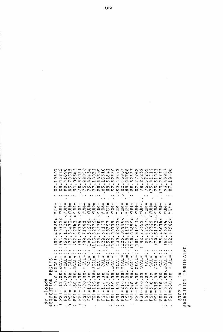
182
H i / i D i n N m c J M c to CM o> C M r~-- CO f-- co CM cr. CM rH CM r-- o
m r-- 10 i n 10 c c j o CM (.a oo (•n j - en ca i^- CM C M Ln c ; N r ; J -O IA H C CO C C C C . O O J - ^ f l O H M C l l D J T J r v Lf> N r< r i « : to ( j ! H c J - h- d ^ c i J - H O P H LP . L ~ : r r ir . r - CM u-\ r*-, c-< -=f r-i
C7! co i n rH en i n i n N o m en CM tn CM c- U D CM cn <_c ir. i_e c"? N~, r~. co oo co cc on r-. r - r». co co co o i en c> t » CO CC i*- r-- r-- co CO
to
CD tu cc
•D O (0 — 0 I—
— : r >
1 o I.1J
i -UJ =tt=
II II II II II II II II n II n ll II II II II II II II II li Ii II II II - i -~ j HI' —-i ZD — 1 ~~< ^) n I T ) -j} ID ZD ZD
>- >- >- > >- >- >- >• ;- 5" >- >- > >• >- >- >• >-
••• r. r'^ ci. -_: cn CM O l-n t-H CS! C I cn r-. i n CM cr« cr-- r-- c - l - l ^+ C1 CO rH cv CO Ln r-- CM rn c - r-f r-t CO C M m C - : i n C-J CM i - l oo i n r«- r~- I-- m CM m CM rH r-l C oo r - oo CT' ic- m i n CO LTs
CD m IT' CM co r-i CM ^± CO rn LTi c<; i - l i n CO CM rH m r-. -=1- i-i N-i CO c hn LTl m C7! CM O r-i o m cc- CO
CM tri C M r-i C O ID m er. CM C-.! m OC o i—t O! -1- C - m CM CM
lO r - CC CP cr- o rH CM C M m K i CM i—1 I - < c co r-- ID irj *-> — -—- •— l-H r-l i - i t-! rH I - I I - I i—i rH rH - •
—- . — — r»- r—• —> —. J— .—. •- .-- - —. r— -. —. - - .
II II II II II II II II II II II II II II II II II II n II II II II II II _ l _ J _ J _ l _ j _ J i _1 _1 1 _ l _ J i _ J _ l 1 _ J _ j _ j <r <; < < <f < • << < <r <r < < <r <; < C_: o o c3 cJ C J ti CJ •Ji cJ. cJ- c j t3
o c - c o c c cr c c c : cr o o c o o cr c c c . c c c o o o c o c . - o r r . o o o c o o o> o o o o o o o o o o
i n c ir-. cr ir-. o m o tr > o m c m o m o m cr m o i n o i n o m o • - - I - H ic- h-- C"= o CM tn m o oo cr> rH c-.i j - t,n oo c H w « to
-> ' " • ' I — ! rH rH r-H rH i—I rH CM C'-' CM CM CM C*J tr*. W> rf- m r^i II II II II II II II II II II II II II II II II II II II II II II II II II
</) co o_ Q- a.
tO CO C O CO 00 I / - . CO CO CO V) (.o to CO CO CO to to ci- G- a. D . O_ tx C L CL. ii. a. ix CL- C L O- a. c. o.
Q I.U
O I -
c CO
3 o LtJ
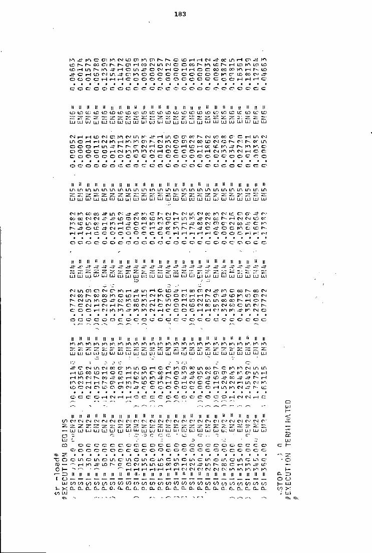
183
On © en On CM to cn on 0 . c LD 1—1 i-H CM ee Ln rH © N1 r-. CO © ! r - r-. cn rH CO CM r-i c © CO on r-- i-i ID On LCI ID
(-C i-H i n 1-n -t i—i © LTl .~*- © CM rH © rH © © oo CO oo on «-l to c r-l to c i ir> © IVl o © © © © © o c © © On © to OC. C-J
o a> o e 1—1 r-H rH © ©• o o © . © o c © © c C c rH i-H i—i ©
cr © c © © c o © © • • c © o © © © • o o tr ©• ©• © © © ©
II II II II II !l II II II II II II II II II II II II II II II II II II II l£) to ID to to to to to 10 tfj t c to l£> t c L£> tC: to ID L O to t c l£T ID tc to
it I?!! 7Z 2 ! — ' •z. 7'-. Zi L±J '.!.! U J L L I UJ U J U J U J U J Ul tiill L J L'J U J UJ LUI UJ U-i UJ LLl L I J LLi LU
CM r-H I C CI © on CM LTi K i-H LT-. © cr o? r» CM tr- OC c © i—' LTi CM LTi O rH r-l CM on rH on On C" f - CM rn © ©i C-J CO to C-5 © . o-~ CM Ot LA © © o f—1 r - CT CM rH O C-J © i-H rH oc tc tn r - on On © O © © C © rH CM on l-n r-n C-l 1-H O C © © r-! rH C-J on on CM t-H © © © © © o c © © © © c © C © ©• © ©• © ©• © © c © © ©•
O © ©• © o © © © ©• © © © © © c © © © O c © © ©
II il II II II ll II II II II II II II II II II II II II II ll II II II II LT: L I i n i n m m Lh i n i n m m i n i n LTi ir , i n m m LT, i n LT, m i n IT. i n 11; — 7~" -•^ ^1 *i~L IZ" lu UJ UJ LU UJ LLI UJ U! LU LU UJ UJ UJ UJ LJJ u- ! UJ LU UJ Lti LU LL!
C M on cc CO J - i n c--: J - K l © r - CM IT. C I CC' rn CM tc cr. CT- r-.1
CO OC CM C-J tc C-J CC- to hn © l-H Ln CM cc r- rH CM CM tC: o: on tc i n OC- •—i i-H c rH f cr © 1—« C>3 C-J CT! C-J CO c i>- J - O LC J - CM r-l © © © l-H or r-- J - © © C © tc r--rH rH rH c O © © © c © © r-i rH r-1 rH rH © © © © I - i t-i
O C © © © © © o © ©. rr- © O © © © © © c- © © © c
II ll II il II II ll ll II ll II II II ll ll II it II II II II II II II II .rj- - j " —i- -S" ^+ -3- .3- -d- •a- 3- _r- -=f
« ^ 5 ~- i : ~~ Ul LLl UJ L U LLJ LLi ul U.I LU • iTi U.1 L L IJJ iLi LU Ul LU UJ L L : L'J LU LU Ul
CM i n en C D CM © on i—i Lfl rH © to l-H OC. © C-J rn C oo r-- oo C-J CM oo OO CO m © to rH CM on © c C--J 1—i r-l o- ^+ to on to ©• CM
r - C-! LTV N-i © cc- on to on rH i n © l-H to CM LTi i n cft C<> r-~ rH o r» C C-J rH C-J l-H © OO CM CM © CM © C-J to CM i n CM C-~- © • LT, c-.;
© © c t-l CM on on on on CM 1—! © © C © rH rH c-? on f i or CM ©
CO C © • o © © • © O © © © ri © © © © © C © © © © • / *•—. -—•- ^ -
ll ll ll II II II II II II ll ll ll II II ll II II II II II II II li II II on on on on on on on on on on on on on on on on on on. on on on i n tn. on on
mi — R x_ s— 5". -LLJ LLI LU l.Lj UJ UJ LU u i UJ UJ LU Ui UJ Ul UJ i l l UJ UJ LU UJ UJ UJ LU LU LLl
J - © CM i n CM OC © on, LTl © rH © c - on ©i 0;5 i n o:. r-- © on on C-l Lfl LTi r-\ to CO to rH © © rH r-i rn ©• oc:> r-l © on —j m c--: ©i © h~, m r-l l—1 on C-I r-. CO oo rH tCs LTi on j - © J - s- c~ J - te ce —j- I - - rH tn C-l rH rH r - cr; rH on r~ to © on r-l © i-H c c rn C-J C-l rH i n C--1 on t c © CM C I tC' C © C-J ji-© © © ©• © c ©. f " I rH LO on CM tc
© c © ©• i—1 CM rH l-H o © © © © © © c © rH C*-l c- . ^ -• • -
•- • — — , - UJ i—
II II II II II II II II II II II II II II II II II II II II II II II ll il (/> C>! C-J C M C-! CM C-J C-.l CM CM r-; CM C-J C-J CM CM CM CM C-! C-l c-f C-J C-i C-l c •
21 2 ; :^ *~* 1 ' 2fT. - I - VL. T" SI 7: . 7 ' — — UJ LL) LiJ UJ LJJ u i LLl Ul U J LU LLJ us i j j L l U J UJ UJ Lu UJ LU Ul UJ LLf UJ- ITT O r.- c. or, " © c: e i U-' U J C2 © © © © © © © © c © © c o © o © c © © © © © © © H~
© © C © r r © © © © © © o © ©• c © © o © © © © ©
O © in © i n © i n © i n o i n © i n © i n © Lfl © LT © m .—• m © Lfl © C fC — rH on ~j- to r - cr © CM on i n to CC © i-f C^l i_n 00 © r-1 on J . tr —
C 1- •-• ,-. I - I rH rH r-l -rH rH rH CM C-J C ! C-J C-i C--.: tn on on on on 1— II II ll II II ll II ll II . ll II II II II II II II II II ll II ll II II II CL r> [ O — o
LU tO t/J tO (/) t/1 tO t/1 t/3 (O LO tO to CO to V) to to to to 00 LO to to to to 1- LU l_. X C L CL. CL. C)_ Cu a. a. CL a. Ci- a. O- D- C L CL a. 0- D. n . a. a. to >:
<rj UJ Ul =*!-- - - - ----- --^
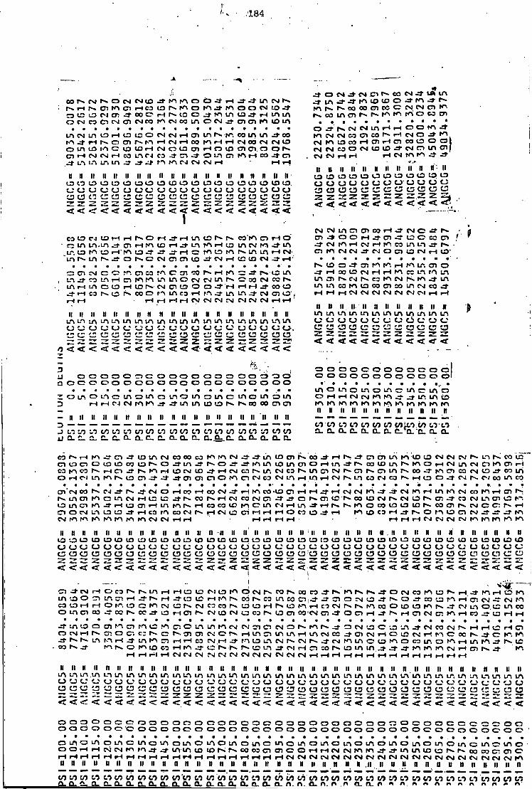
,184
oo i v CNI rv o CM CM ID st rn rA O o - a rH J - J - m CM t v j i n * J to I D o d - w r v I-H rv cn m c i rH CO LO rv m o m m O O CM LO St m r v s w oo en oe c CM CM C? O 13 LO CM o i CO O l - l rv to o .a- i n i n tO rH i n i n co i n c n r v r v r A r n m o c o O CM CO en CM C I CM CO rA CM OO i n O CM - a en cn m L O m
o st r v CM CM i n rH rH o o m m CM W LO rH 13 I D O CM CM rH O"! i n rv co m i n CO m CM CM CO C I CO rv rH N O J m . a rH rv o en r - m rH CM rH CO m t-i rH CM oo CM CM 13 CM m to co i-H m rH en OO LO O o i n LO lO ID rH CM O lO <T> rH o U3 cn en. o O rv CM CM CO O ( S ID 13 J CM o i n C I rH CM CM rH CO L A CM CO -1- C I .a- o i n cn m rH CO - a en . CM CM rH rH rH CM m m .a-j L t W W in ^ ^ j n w r j CM N H
I I I I I I I I I I I I I I I I I I I I I I I I I I I I I I I I I I I I I I I I O l O l O l O l O l O l O l O l O i a i O L O l O l O L O l O l D L O l O l O . c u u c u u u u u u u o u u u u u u u u C D C J C ^ C J C J C D C J C J C D C J C D C J C J C J C D C D C D C J C J C D
< < < < r < < < < r < f < < < < < < < < < < <
o l
I I n ii ii n it ii ii ii ii 1 3 G 0 0 1 3 1 3 0 I 3 1 3 0 U U U C J O O U O U U a c D C D C J C D C J C D C D C J C J Z Z Z Z Z Z Z Z Z Z j
«r < < < < < «f-
I I u LO LO o o CD CJ 2 z <r < < < <
CM CM i n cn cn CO rH St CM C -3-CO to CN L O rH rH rv o rH st rH L A CO r v co rn cn rH o cn J * o o rH J - cn st CO o CO cn
i n L A . i n -if cn rH.*n LO rH J - L A m rH LO m CM m i n St CM r n rH CM rH CO m m J -LO m to i—1 m L O J 1 St rH m LO rn rv. i n i n rH CM en KY CM CM -a- C J o en to CM rH L O
i n rv i n r-~ si o rv c CM en cn L O — CM rH to LO CM J - rH LO o J - cn rn r^. rH r n m cn o
en CM c i—» cn co r n c cn co r v rH t n z: -a- f*. LO i n j - rH 00 LO CM rH rH r n ec m rn i n m . a CO LA rH cn m m LA i n o CM CM m 30 CM CO r~- i n C7) r-^ CM r-. C3 rn CM r< rn St i n i n rH i n c LO rH L O rv CM en LO O o J " rH rH rH J " CO L O m tn cs m L O CO en SO m eg CO •—i rH CO rv LO rv co o rA i n CO rH m J - i n m J - CM cn LO , rH rH rH CM CM CM CM CM CM CM rH rH rH rH rH rH rH rH CM CM CM CM CM CM CM rH rH '
N I I I I I I I I I I I I I I I I I I I I I I I I I I I I I I I I I I D I I I I I I I I I I I I I I I I I I I I I I I I I I m i n m m m i n i n m m i n i n i n
LA i n i n m i n i n m i n m i n m m i n i n i n i n m i n L-> i n C J C J C J C J C J C J C J C J c i C J o C J C J * * o C J C J C J C J C J C J C J C J C J C J C J a C J C J o . r n C3 C3 a c ;
z z 13
( j *— C J try CD t r< c i ID C3 C3 C3 C3 z z z z z z z a c ; z z Z z
Z 2 2 2 Z 2 Z zz z z T 7* z z T* Z Z < < <r < < < 5 < < < «r n < < <
u o a o e o o c j c o o o o o o o o o o o o o Q O C O O O O O O O O O O O O O G O O O O O
loiflOLicinotfiowomsmcinoiflsm D rH rH c-i CM m K > m i n to to i*^ r*. oo oo en cn
- it I I I I I I I I I I I I I I I I I I I I I I n I I I I I I I I I I I I n D 1
J t/i t/} CO 1/5 0 0 0 0 tO CO W W CO 00 tT W CO CO tO CO CO u o . i a . c . c . o . f l . t . c . Q . f l . 1 1 . a - 0 - . c 0 . 0 . 0 . 0 . 0 .
o o o o c o o o o c o o o 0 0 0 0 0 0 0 0 0 0 0 0
m o L.n o m o m o i n er i n o
11 11 11 11 11 11 li 11 11 11 11 it
M M t*} ITi I/) CO COitO.CO M M o . o . o . o. o . o . o . 0 . o . o . o . a .
C3 ST c i J * to i n CM CO 00 CO rA rn CM J - J LTl 10 01 s 00 d - H 0 a en 01 m rn t o LO CM CM CM rv i n pv CO LQ en LO cn 0 t o to CO t o 0 -a- i n .a- r~- 0 m i n DO t o m rv rn 0 rH CM i n CM en rn cr> rH co hn oo r-». I-H O St rH LO CM to J - rH CM co r-» I T . CM co r» m en CM r v cn cn i n iv. CO st m en CO CM t o st CO m O r i N i n rA r - t o C I J - J - st cn cn O O K I en CM co CM LTl i-H i n rH CM rv i n CO C<l CO rv. r-H LO 0 st CM rv CM CO i n co
on 'CM 00 CM St I--. CM O rH CO rH CO CM St m co •to CT rH rH st rH CM CM st st CM rA rH i n N"» CM CO m rH cn i n cn a m CM rH LO to J- tv CO rH CM co CM cn a J O K O I I S r-~ co t o CM p*. CM 0 r » en st CO CM i n cn to
L O i n cn r n st rH to en rH m r n 1 ^ rH CO CO t o m c i n N H i n a n s 0 CO to to LO r v co en rv CM 0 cr. rv. rH CD 0 CM m LO LO St rH CO m CO CM r» rH CM t o C I rH rH rH O CO ID a H to CO rH Pv 0 r-\ t o CT CM St st m CM m m m pn tr\ m m CM CM rH rH rH rH rH rH rH CM CM CM CM rn m m pn
11 11 11 11 I I I I 11 I I I I 11 I I I I 11 I I I I 11 I I I I I I I I I I I I : I I I I I I I I 11 n n I I I I I I I I I I I I I I I I I I I I 11 11 10 to to to to to to to to LO to to to to to to to to to LO t o to to 10 t o to to to to to LO LO LO LO tO to to to to t o to CJ CJ CJ CJ 0 0 CJ CJ CJ CJ CJ CJ CJ O CJ CJ CJ CJ CJ CJ CJ CJ CJ O CJ CJ CJ CJ CJ CJ CJ CJ CJ CJ CJ CJ CJ CJ CJ CJ CJ CJ: to a CJ C3 C3 O CD O C3 O CJ 0 O C ! O u 0 o u 0 0 O CD CD 0 CD CD CD a CD CD CJ cr- CD <S> CJ 0 z z z z z z z z z z z z z z z z Z Z 2 Z Z Z z~ z zz z z z z zz < < < < < <r < < < < << < < < <r < < < <<<<<< < < < < < < < < < < < < < < <t < !
cn st CM rH O CO r v m rH rH LO t o C J LO m 1
O CM r - CO rv CO CO st rv m r*. r*. J - O CM CO m to r»» rH -a rn rH co m i n to 0 C I t n en rH .a- rv rH st lO to rH m rv CO CO i n co Cltst st CT 0 CM LO st O st CO to PA rH en CM -a- CN r n CO to rH rH 0 m LO 0 m CN LO r-» CM C3 CO rv to to rH rv to rs\ rH CO CM rv r v m 00 0 to to m r>» J - CN m 0 . to m co 0 Ln en CO —4 CO r» cc st to rH cn CM tO CM to CO pv to cn CO CM en J " 0 en rH st rv rH cn CM cn rA rH co LO rH rH
J - i n to 0 en rn CI r n to m CI O m m rn CN CN CT cn CM CO rv m rv st O CM to 0 to m st CM CO CM rv rH rH to rH O CM rH CP! 0 cr. C3 rv. r v C I en CM 0 r v rH i n en tn i n rH m CM co st cn CM rH 0 to ( M H M C o e rv -a- c m - a rv i n m rH —4 i n m cn rH rH CO CM rH st m to m CM rv CM r v .a- CM m i n 0 to m 0 co i n 0 m rH i n m st I V . CO r>. J - m I V . 0 m to CO rH m .a- LO tv rv r v 10 i n st CM rH cn co rv to i n m st st st m m m CM rH cn r v st
rH rH r-l rH CM CN CM CM CN CM CM CM CN CN CM CM
I I I I I I I I I I I I I I I I I I I I I I I I I I I I I I I I I I I I I I I I I I I I I I I I I I I I I I I I I I I I I I I I I I I I I I I I I I I I I I I I I I m i n i n . i n L A i n i n i n i n Ln i n m i n i n i n i n i n i n i n i n i n i n i n m w i n i n i n i n i n i n i n tn i n w i n tn tn i n i n i n o CJ u u c U ( J u c j u CJ '~: u CJ L ; ' J ( J u u c j u u c u o u ( J t ) CJ CJ C_> CJ '^J u CJ CJ CJ O C D C J C D C J C D C D C J C D C D C D C D O C J
< < < r < < < < < < 5 < < < < < < < < < < < < < < < < < < < < < < < < < < < < < < <
O O O O O C O O O O O O O C O O O O O O O O O O O O O O O O O O O O O C C C O O C O O 0 0 0 0 0 0 0 O O O O O O O O O O O O O O O O O O O O O O O O O O O O O O O O O O
o i n o i n o L A C i n o t n o i n o t n o L n o i n o i n o L n o i n o u n o i n o w o i n o i n O L A C L n o i n o O O r H r H C M C M r A r n j - J - i 0 U 3 N M » C 5 a 0 1 C O H H ( N N W W a a i f l i n i 0 l 3 N N 0 0 C 0 C : C J l C rH rH rH H H H rH rH rH rH rH rH rH rH rH rH rH rH rH rH CM CM' CM CM CM CM CM CM CM CM CM CM CM CM CM CM CM CM CN CM m 11 11 11 11 11 11 11 11 11 11 11 n 11 11 11 11 11 11 11 11 11 11 11 11 11 11 11 11 11 11 11 11 n u 11 n 11 11 11 11 11
tO 00 00 00 C0 00 tO 00 CO tO tO CO CO tO CO tO M C0 CO CO tO CO CO CO tO tO tO CO M M M M M CO CO CO M M CO M CO C 3 - P . P . O - P . Q . Q . O . Q . Q . Q . Q . Q . P . Q . Q . C U O _ Q . C ^ n . n . O - n . r > r> CL a . n » n r> n n r* r* n n r > » o
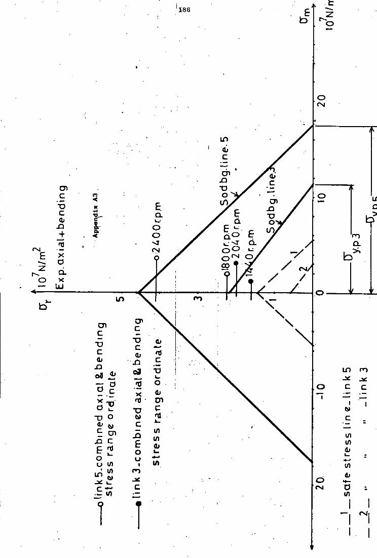
i n
cn
cn in
a o £ / f
b 00
LU ID
in m
TO
(ft
l / l I in in a)
in in
1 " I
187
REFERENCES
( 1 ) Chen, F.Y. An a n a l y t i c a l method for synthesizing the four-bar crank-rocker mechanism. Journal of Engineering for Industry, Trans. ASME February 1969. p. 45-54
(2 ) Lord, P.R. and Mohamed, M.H. An analysis of the picking mechanism of a t e x t i l e loom. Journal of Engineering for Industry, Trans. ASME. May 1975. p. 385-390
( 3 ) Bevan,.'T. The Theory of Machines. Longmans, Green & Co. Ltd., 1964
( 4 ) Conte, F.L., George, G.R., Mayne, R.W., and Sadler, J.P. Optimum Mechanism Design combining Kinematic and Dynamic-Force considerations. Journal of Engineering for Industry, Trans. ASME. May 1975, p. 662-670
( 5 X Spotts, M.F. Design of Machine Elements (4th E d i t i o n ) . Brentice-Hall Inc. Englewood C l i f f s , N.J., U.S.A. 1971
( 6 ) Dove, R.C. and Adams, P.H. Experimental Stress Analysis and Motion Measurement. Charles E. M e r i l l Books. Inc., Ohio, U.S.A. 1964
( 7 ) Marin, J . Mechanical Behaviour of Engineering Materials. Prentice-Hall Inc., Englewood C l i f f s , N.J., U.S.A. 1962
( 8 ) Green, W.G. Theory of Machines (2nd Edition) Blackie & Son Ltd., 1962
( 9^ Shigley, J.E. Theory of Machines (International Student Ed.) McGraw-H i l l Book Co. Inc. 1961
0-10) Tepper, F.R. and Lowen, G.G. Shaking Force Optimisation of Four-bar Linkage with Adjustable Constraints on Ground Bearing Forces. Journal of Engineering for Industry, Trans. ASME. May 1975, p 643-651
(11.) Wojcik, C.K. Synthesis of Four-bar Linkage Function generators by means of Equations of Motion. Journal of Engineering for Industry. Trans. ASME. May 1965. p. 170-176
(12 ) Maxwell, R.L. Kinematics and Dynamics of Machinery. Prentice H a l l , Inc. Englewood C l i f f s , N.J., U.S.A. 1960
(13 ) Prentis, J.M. Dynamics of Mechanical Systems. Longman Group Ltd., Great B r i t a i n 1970
188
(14) Morrison, J.L.M. and Crossland, B. An introduction to the Mechanics of Machines. Longman Group Ltd., Great B r i t a i n . 1970
(15) Alexander, R.M. and Lawrence, K.L. Experimentally Determined Dynamic Strains i n an E l a s t i c Mechanism. Journal of Engineering for Industry, Trans. ASME 1974. Paper No. 74 - DET - 33
(16) Dubowsky, S., and Young, S.C. An Experimental and An a l y t i c a l Study of Connection Forces i n High-Speed Mechanisms. Journal of Engineering for Industry, Trans. ASME 1974. Paper No. 74 - DET - 72
(17) Singer, F.L. Strength of Materials (Second E d i t i o n ) . Harper and Row, Publishers. 1962
(18) Roark, R.J. Formulas for Stress and Stra i n . (Fourth Edition) McGraw-H i l l Book Company 1965
(19) Holister, G.S. Experimental Stress Analysis. Cambridge University Press. 1967.
(20) Heywood, R.B. Designing Against Fatigue. Chapman and Hall Ltd., 1962
(21) Holowenko, A.R. Dynamics of Machinery. John Wiley & Sons. Inc. 1963
(22) Hinkle, R.T. Kinematics of Machines. Prentice-Hall, Inc. Englewood C l i f f s , N.J., U.S.A. 1953
(23) Rayevskii, N.P. The Measurement of Mechanical Parameters in Machines. Pergamon Press. Ltd., 1965
(24) Greenwood*, J.M. Stresses i n the-Reed and Weft Needle Arm. of a Weaving Loom. F i n a l Year Honours Project. May 1974. University of Durham. Department of Engineering Science.
(25) Imam, I . , and Sandor, G.N. High-Speed Mechanicsm Design - A General Ana l y t i c a l Approach. Journal of Engineering for Industry. Trans. ASME. May 1975. Paper No. 74 - DET - 50
(26) Fa i r e s , V.M. Design of Machine Elements (4th E d i t i o n ) . Macmillan Co. 1962, U.S.A.
'2 4'W0VV?76 4
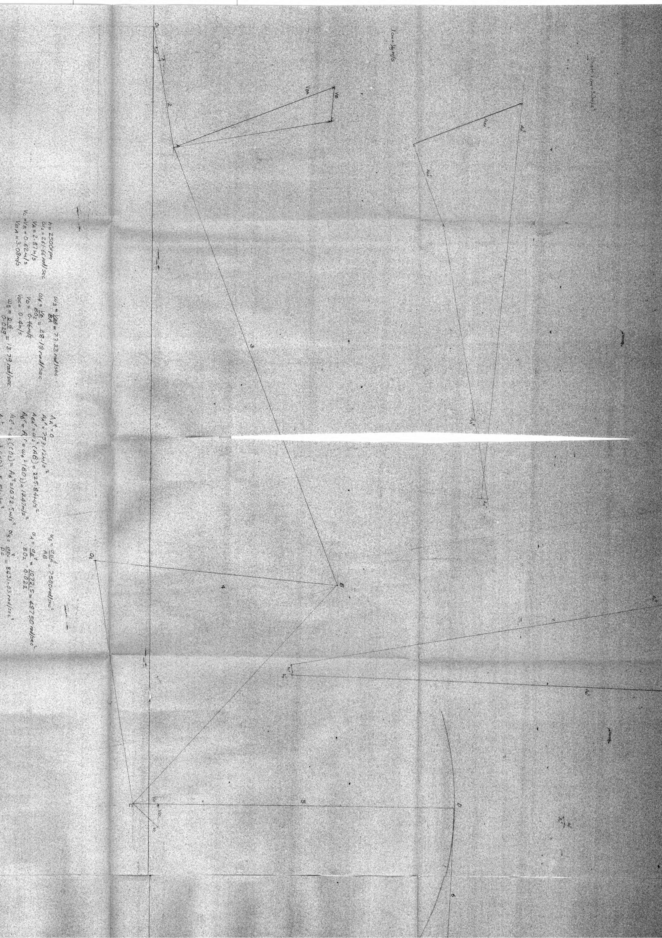
Si
-v.