durus controllers system manual,...
TRANSCRIPT
GE Fanuc Automation Programmable Control Products
DURUS Controllers System Manual GFK-2470
June 2007
GFL-002
Warnings, Cautions, and Notes as Used in this Publication
Warning
Warning notices are used in this publication to emphasize that hazardous voltages, currents, temperatures, or other conditions that could cause personal injury exist in this equipment or may be associated with its use.
In situations where inattention could cause either personal injury or damage to equipment, a Warning notice is used.
Caution
Caution notices are used where equipment might be damaged if care is not taken.
Note Notes merely call attention to information that is especially significant to understanding and operating the equipment.
This document is based on information available at the time of its publication. While efforts have been made to be accurate, the information contained herein does not purport to cover all details or variations in hardware or software, nor to provide for every possible contingency in connection with installation, operation, or maintenance. Features may be described herein which are not present in all hardware and software systems. GE Fanuc Automation assumes no obligation of notice to holders of this document with respect to changes subsequently made.
GE Fanuc Automation makes no representation or warranty, expressed, implied, or statutory with respect to, and assumes no responsibility for the accuracy, completeness, sufficiency, or usefulness of the information contained herein. No warranties of merchantability or fitness for purpose shall apply.
The following are trademarks of GE Fanuc Automation, Inc.
Alarm Master Genius ProLoop Series Six CIMPLICITY Helpmate PROMACRO Series Three CIMPLICITY 90–ADS Logicmaster PowerMotion VersaMax CIMSTAR Modelmaster PowerTRAC VersaPoint Field Control Motion Mate Series 90 VersaPro GEnet PACSystems Series Five VuMaster Proficy Series One Workmaster
©Copyright 2007 GE Fanuc Automation North America, Inc.
All Rights Reserved
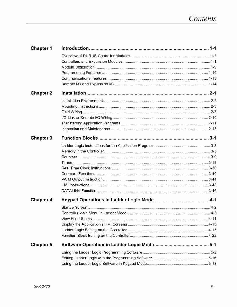
Contents
GFK-2470 iii
Chapter 1 Introduction............................................................................................ 1-1 Overview of DURUS Controller Modules .......................................................................... 1-2 Controllers and Expansion Modules ................................................................................. 1-4 Module Description ........................................................................................................... 1-9 Programming Features ................................................................................................... 1-10 Communications Features .............................................................................................. 1-13 Remote I/O and Expansion I/O ....................................................................................... 1-14
Chapter 2 Installation.............................................................................................. 2-1 Installation Environment.................................................................................................... 2-2 Mounting Instructions ........................................................................................................ 2-3 Field Wiring ....................................................................................................................... 2-7 I/O Link or Remote I/O Wiring ......................................................................................... 2-10 Transferring Application Programs.................................................................................. 2-11 Inspection and Maintenance ........................................................................................... 2-13
Chapter 3 Function Blocks..................................................................................... 3-1 Ladder Logic Instructions for the Application Program ..................................................... 3-2 Memory in the Controller................................................................................................... 3-3 Counters............................................................................................................................ 3-9 Timers ............................................................................................................................. 3-19 Real Time Clock Instructions .......................................................................................... 3-30 Compare Functions......................................................................................................... 3-40 PWM Output Instruction .................................................................................................. 3-44 HMI Instructions .............................................................................................................. 3-45 DATALINK Function........................................................................................................ 3-46
Chapter 4 Keypad Operations in Ladder Logic Mode.......................................... 4-1 Startup Screen .................................................................................................................. 4-2 Controller Main Menu in Ladder Mode.............................................................................. 4-3 View Point States ............................................................................................................ 4-11 Display the Application’s HMI Screens ........................................................................... 4-13 Ladder Logic Editing on the Controller............................................................................ 4-15 Function Block Editing on the Controller ......................................................................... 4-22
Chapter 5 Software Operation in Ladder Logic Mode.......................................... 5-1 Using the Ladder Logic Programming Software ............................................................... 5-2 Editing Ladder Logic with the Programming Software.................................................... 5-16 Using the Ladder Logic Software in Keypad Mode......................................................... 5-18
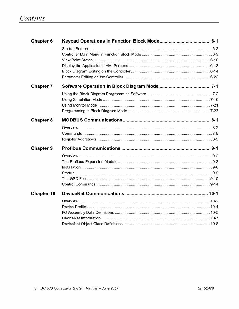
Contents
iv DURUS Controllers System Manual – June 2007 GFK-2470
Chapter 6 Keypad Operations in Function Block Mode....................................... 6-1 Startup Screen .................................................................................................................. 6-2 Controller Main Menu in Function Block Mode ................................................................. 6-3 View Point States ............................................................................................................ 6-10 Display the Application’s HMI Screens ........................................................................... 6-12 Block Diagram Editing on the Controller ......................................................................... 6-14 Parameter Editing on the Controller................................................................................ 6-22
Chapter 7 Software Operation in Block Diagram Mode ....................................... 7-1 Using the Block Diagram Programming Software............................................................. 7-2 Using Simulation Mode ................................................................................................... 7-16 Using Monitor Mode ........................................................................................................ 7-21 Programming in Block Diagram Mode ............................................................................ 7-23
Chapter 8 MODBUS Communications................................................................... 8-1 Overview ........................................................................................................................... 8-2 Commands........................................................................................................................ 8-5 Register Addresses........................................................................................................... 8-9
Chapter 9 Profibus Communications .................................................................... 9-1 Overview ........................................................................................................................... 9-2 The Profibus Expansion Module ....................................................................................... 9-3 Installation ......................................................................................................................... 9-6 Startup............................................................................................................................... 9-9 The GSD File................................................................................................................... 9-10 Control Commands ......................................................................................................... 9-14
Chapter 10 DeviceNet Communications ............................................................... 10-1 Overview ......................................................................................................................... 10-2 Device Profile .................................................................................................................. 10-4 I/O Assembly Data Definitions ........................................................................................ 10-5 DeviceNet Information..................................................................................................... 10-7 DeviceNet Object Class Definitions ................................................................................ 10-8
GFK-2470 1-1
Introduction
This chapter describes the Durus controller family of products. It lists the available modules, and gives their specifications.
Chapter 2, Installation, describes module installation and wiring.
Chapter 3, Program Functions, defines the coils, contacts, logic blocks, and function blocks that can be used in an application program.
Chapter 4, Keypad Operations in Ladder Logic Mode, explains how to navigate the controller LCD screens and make changes using the keypad, in Ladder Logic mode.
Chapter 5, Software Operation in Ladder Logic Mode, explains how use the programming software for programming, simulation, and emulation in Ladder Logic mode.
Chapter 6, Keypad Operations in Function Block Diagram Mode, explains how to navigate the controller LCD screens and make changes using the keypad, in Block Diagram mode.
Chapter 7, Software Operations in Function Block Diagram Mode, explains how use the programming software for programming, simulation, and emulation in Block Diagram mode.
Chapter 8, MODBUS Communications, describes the MODBUS features that can be incorporated into a Durus controller system.
Chapter 9, Profibus Communications, describes how the Profibus-DP Expansion Module can be used to add Profibus slave communications to a Durus controller.
Chapter 10, DeviceNet Communications, describes how the DeviceNet Expansion Module can be used to add DeviceNet slave communications to a Durus controller.
Chapter
1
1-2 DURUS Controllers System Manual – June 2007 GFK-2470
1
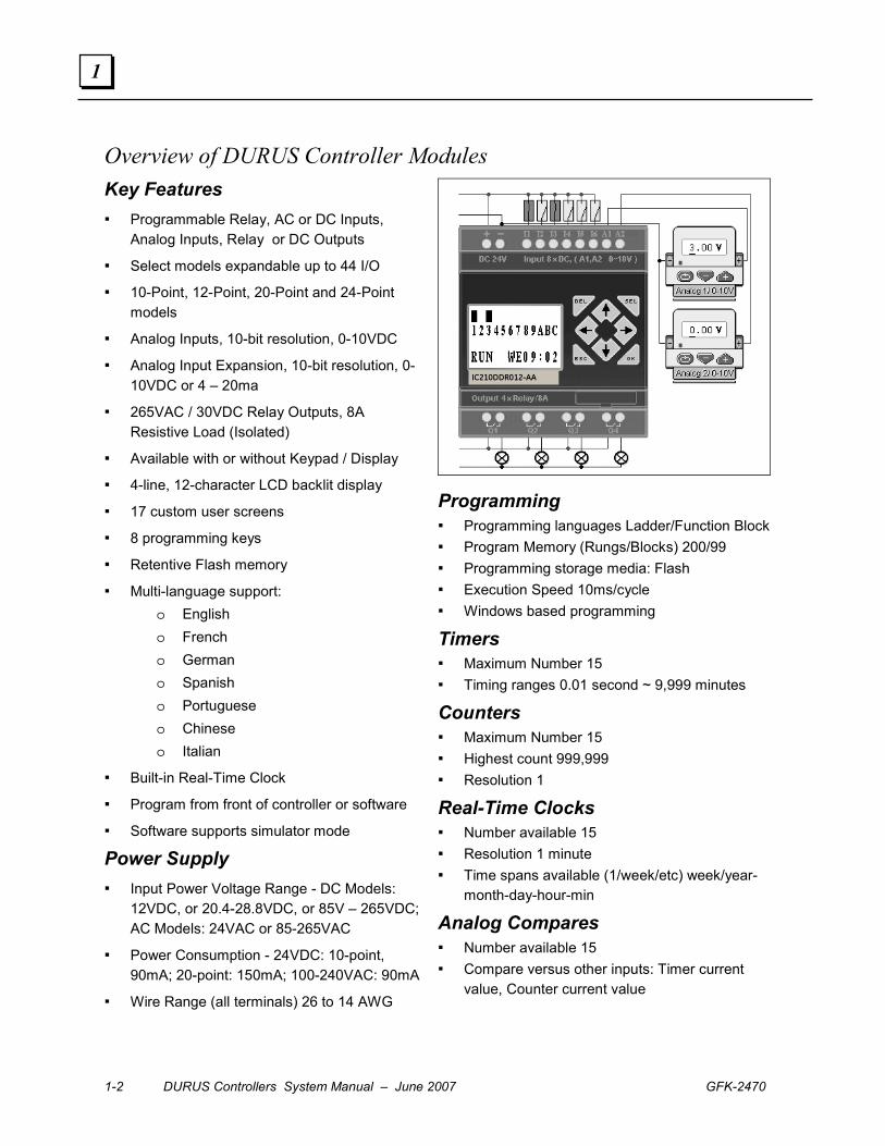
Overview of DURUS Controller Modules Key Features ▪ Programmable Relay, AC or DC Inputs,
Analog Inputs, Relay or DC Outputs
▪ Select models expandable up to 44 I/O
▪ 10-Point, 12-Point, 20-Point and 24-Point models
▪ Analog Inputs, 10-bit resolution, 0-10VDC
▪ Analog Input Expansion, 10-bit resolution, 0-10VDC or 4 – 20ma
▪ 265VAC / 30VDC Relay Outputs, 8A Resistive Load (Isolated)
▪ Available with or without Keypad / Display
▪ 4-line, 12-character LCD backlit display
▪ 17 custom user screens
▪ 8 programming keys
▪ Retentive Flash memory
▪ Multi-language support: o English o French o German o Spanish o Portuguese o Chinese o Italian
▪ Built-in Real-Time Clock
▪ Program from front of controller or software
▪ Software supports simulator mode
Power Supply
▪ Input Power Voltage Range - DC Models: 12VDC, or 20.4-28.8VDC, or 85V – 265VDC; AC Models: 24VAC or 85-265VAC
▪ Power Consumption - 24VDC: 10-point, 90mA; 20-point: 150mA; 100-240VAC: 90mA
▪ Wire Range (all terminals) 26 to 14 AWG
IC210DDR012-AA
Programming ▪ Programming languages Ladder/Function Block ▪ Program Memory (Rungs/Blocks) 200/99 ▪ Programming storage media: Flash ▪ Execution Speed 10ms/cycle ▪ Windows based programming
Timers ▪ Maximum Number 15 ▪ Timing ranges 0.01 second ~ 9,999 minutes
Counters ▪ Maximum Number 15 ▪ Highest count 999,999 ▪ Resolution 1
Real-Time Clocks ▪ Number available 15 ▪ Resolution 1 minute ▪ Time spans available (1/week/etc) week/year-
month-day-hour-min
Analog Compares ▪ Number available 15 ▪ Compare versus other inputs: Timer current
value, Counter current value
GFK-2470 Chapter 1 Installation 1-3
1
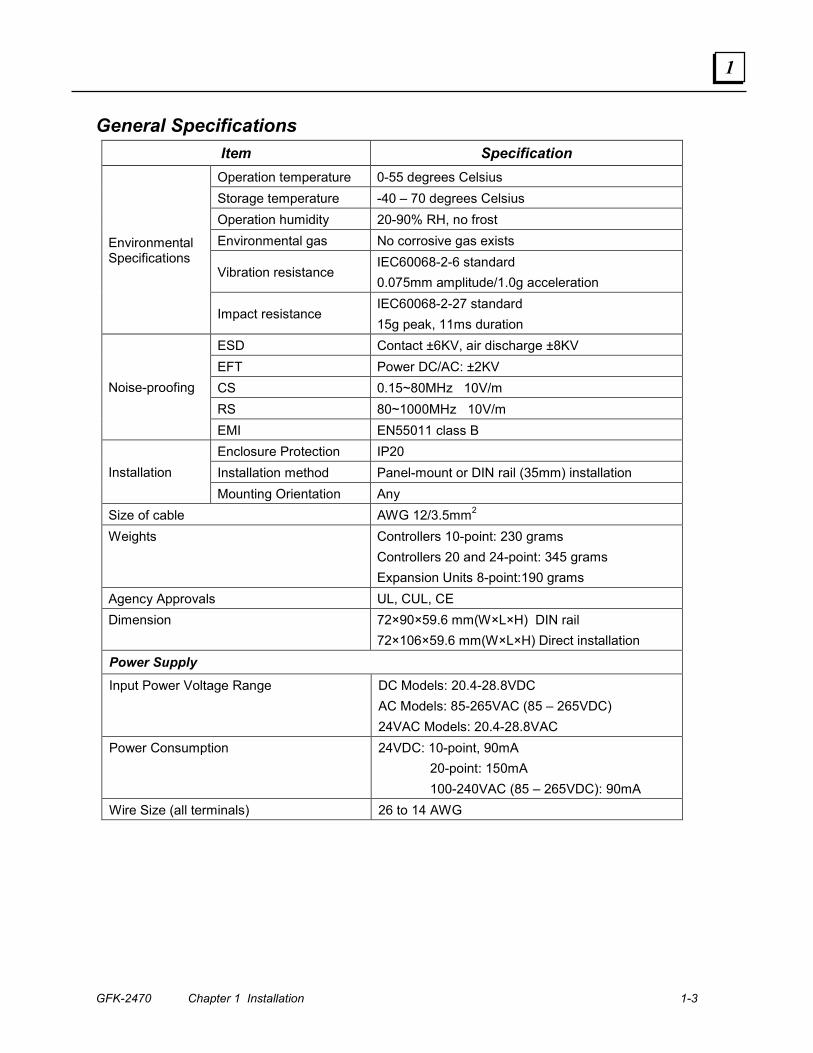
General Specifications Item Specification Operation temperature 0-55 degrees Celsius Storage temperature -40 – 70 degrees Celsius Operation humidity 20-90% RH, no frost Environmental gas No corrosive gas exists
Vibration resistance IEC60068-2-6 standard 0.075mm amplitude/1.0g acceleration
Environmental Specifications
Impact resistance IEC60068-2-27 standard 15g peak, 11ms duration
ESD Contact ±6KV, air discharge ±8KV EFT Power DC/AC: ±2KV CS 0.15~80MHz 10V/m RS 80~1000MHz 10V/m
Noise-proofing
EMI EN55011 class B Enclosure Protection IP20 Installation method Panel-mount or DIN rail (35mm) installation Installation Mounting Orientation Any
Size of cable AWG 12/3.5mm2 Weights Controllers 10-point: 230 grams
Controllers 20 and 24-point: 345 grams Expansion Units 8-point:190 grams
Agency Approvals UL, CUL, CE Dimension 72×90×59.6 mm(W×L×H) DIN rail
72×106×59.6 mm(W×L×H) Direct installation Power Supply Input Power Voltage Range DC Models: 20.4-28.8VDC
AC Models: 85-265VAC (85 – 265VDC) 24VAC Models: 20.4-28.8VAC
Power Consumption 24VDC: 10-point, 90mA 20-point: 150mA 100-240VAC (85 – 265VDC): 90mA
Wire Size (all terminals) 26 to 14 AWG
1-4 DURUS Controllers System Manual – June 2007 GFK-2470
1
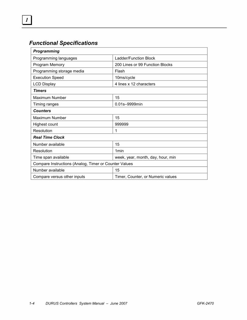
Functional Specifications Programming Programming languages Ladder/Function Block Program Memory 200 Lines or 99 Function Blocks Programming storage media Flash Execution Speed 10ms/cycle LCD Display 4 lines x 12 characters Timers Maximum Number 15 Timing ranges 0.01s–9999min Counters Maximum Number 15 Highest count 999999 Resolution 1 Real Time Clock Number available 15 Resolution 1min Time span available week, year, month, day, hour, min Compare Instructions (Analog, Timer or Counter Values Number available 15 Compare versus other inputs Timer, Counter, or Numeric values
GFK-2470 Chapter 1 Installation 1-5
1
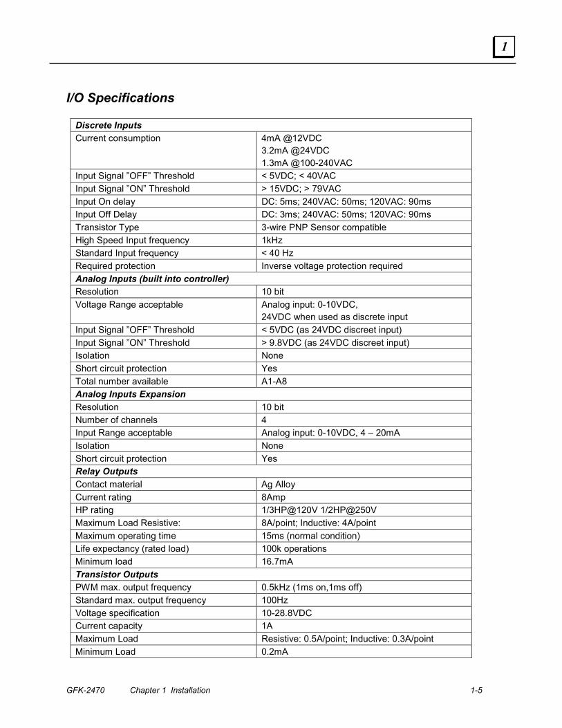
I/O Specifications
Discrete Inputs Current consumption 4mA @12VDC
3.2mA @24VDC 1.3mA @100-240VAC
Input Signal ”OFF” Threshold < 5VDC; < 40VAC Input Signal ”ON” Threshold > 15VDC; > 79VAC Input On delay DC: 5ms; 240VAC: 50ms; 120VAC: 90ms Input Off Delay DC: 3ms; 240VAC: 50ms; 120VAC: 90ms Transistor Type 3-wire PNP Sensor compatible High Speed Input frequency 1kHz Standard Input frequency < 40 Hz Required protection Inverse voltage protection required Analog Inputs (built into controller) Resolution 10 bit Voltage Range acceptable Analog input: 0-10VDC,
24VDC when used as discrete input Input Signal ”OFF” Threshold < 5VDC (as 24VDC discreet input) Input Signal ”ON” Threshold > 9.8VDC (as 24VDC discreet input) Isolation None Short circuit protection Yes Total number available A1-A8 Analog Inputs Expansion Resolution 10 bit Number of channels 4 Input Range acceptable Analog input: 0-10VDC, 4 – 20mA Isolation None Short circuit protection Yes Relay Outputs Contact material Ag Alloy Current rating 8Amp HP rating 1/3HP@120V 1/2HP@250V Maximum Load Resistive: 8A/point; Inductive: 4A/point Maximum operating time 15ms (normal condition) Life expectancy (rated load) 100k operations Minimum load 16.7mA Transistor Outputs PWM max. output frequency 0.5kHz (1ms on,1ms off) Standard max. output frequency 100Hz Voltage specification 10-28.8VDC Current capacity 1A Maximum Load Resistive: 0.5A/point; Inductive: 0.3A/point Minimum Load 0.2mA
1-6 DURUS Controllers System Manual – June 2007 GFK-2470
1
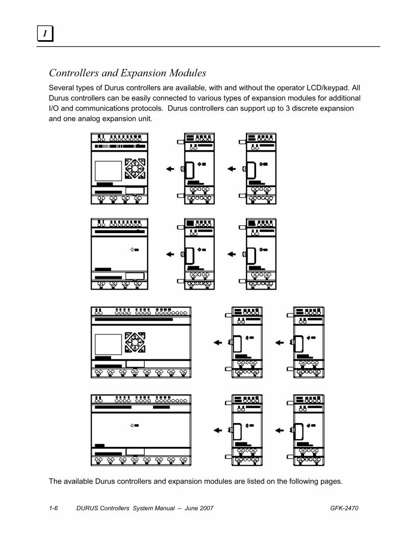
Controllers and Expansion Modules Several types of Durus controllers are available, with and without the operator LCD/keypad. All Durus controllers can be easily connected to various types of expansion modules for additional I/O and communications protocols. Durus controllers can support up to 3 discrete expansion and one analog expansion unit.
The available Durus controllers and expansion modules are listed on the following pages.
GFK-2470 Chapter 1 Installation 1-7
1
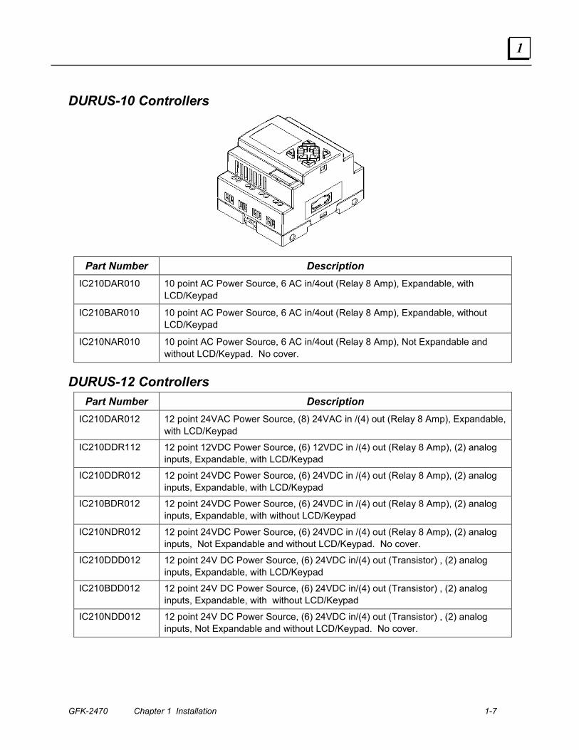
DURUS-10 Controllers
Part Number Description IC210DAR010 10 point AC Power Source, 6 AC in/4out (Relay 8 Amp), Expandable, with
LCD/Keypad
IC210BAR010 10 point AC Power Source, 6 AC in/4out (Relay 8 Amp), Expandable, without LCD/Keypad
IC210NAR010 10 point AC Power Source, 6 AC in/4out (Relay 8 Amp), Not Expandable and without LCD/Keypad. No cover.
DURUS-12 Controllers Part Number Description
IC210DAR012 12 point 24VAC Power Source, (8) 24VAC in /(4) out (Relay 8 Amp), Expandable, with LCD/Keypad
IC210DDR112 12 point 12VDC Power Source, (6) 12VDC in /(4) out (Relay 8 Amp), (2) analog inputs, Expandable, with LCD/Keypad
IC210DDR012 12 point 24VDC Power Source, (6) 24VDC in /(4) out (Relay 8 Amp), (2) analog inputs, Expandable, with LCD/Keypad
IC210BDR012 12 point 24VDC Power Source, (6) 24VDC in /(4) out (Relay 8 Amp), (2) analog inputs, Expandable, with without LCD/Keypad
IC210NDR012 12 point 24VDC Power Source, (6) 24VDC in /(4) out (Relay 8 Amp), (2) analog inputs, Not Expandable and without LCD/Keypad. No cover.
IC210DDD012 12 point 24V DC Power Source, (6) 24VDC in/(4) out (Transistor) , (2) analog inputs, Expandable, with LCD/Keypad
IC210BDD012 12 point 24V DC Power Source, (6) 24VDC in/(4) out (Transistor) , (2) analog inputs, Expandable, with without LCD/Keypad
IC210NDD012 12 point 24V DC Power Source, (6) 24VDC in/(4) out (Transistor) , (2) analog inputs, Not Expandable and without LCD/Keypad. No cover.

1-8 DURUS Controllers System Manual – June 2007 GFK-2470
1
DURUS-20 Controllers
Part Number Description IC210DAR020 20 point AC Power Source, (12) AC in/8 out (Relay, 8 Amp), Expandable, with
LCD/Keypad IC210BAR020 20 point AC Power Source, (12) AC in/8 out (Relay, 8 Amp), Expandable, with
without LCD/Keypad IC210NAR020 20 point AC Power Source, (12) AC in/8 out (Relay, 8 Amp), Not Expandable,
without LCD/Keypad. No cover.
DURUS-24 Controllers Part Number Description
IC210MDR124 24 point 12V DC Power Source, (12) 12VDC in/8 out (Relay, 8 Amp), (4) analog inputs, Expandable, with LCD/Keypad.
IC210DDR024 24 point 24V DC Power Source, (12) 24VDC in/8 out (Relay, 8 Amp), (4) analog inputs, Expandable, with LCD/Keypad
IC210BDR024 24 point 24V DC Power Source, (12) 24VDC in/8 out (Relay, 8 Amp), (4) analog inputs, Expandable, without LCD/Keypad
IC210NDR024 24 point 24V DC Power Source, (12) 24VDC in/8 out (Relay, 8 Amp), (4) analog inputs, not expandable, without LCD/Keypad. No cover.
IC210DDD024 24 point 24V DC Power Source, (12) 24VDC in/(8) out (Transistor), (4) analog inputs, Expandable, with LCD/Keypad
IC210BDD024 24 point 24V DC Power Source, (12) 24VDC in/(8) out (Transistor) , (4) analog inputs, Expandable, without LCD/Keypad
IC210NDD024 24 point 24V DC Power Source, (12) 24VDC in/(8) out (Transistor) , (4) analog inputs, not expandable, without LCD/Keypad. No cover.
IC210MDR024 24 point 24V DC Power Source, (12) 24VDC in/8 out (Relay, 8 Amp), (4) analog inputs, Expandable, with LCD/Keypad. Supports Modbus Slave on port.
IC210MDD024 24 point 24V DC Power Source, (12) 24VDC in/(8) out (Transistor) , (4) analog inputs, Expandable, with LCD/Keypad. Supports Modbus Slave on port.
GFK-2470 Chapter 1 Installation 1-9
1
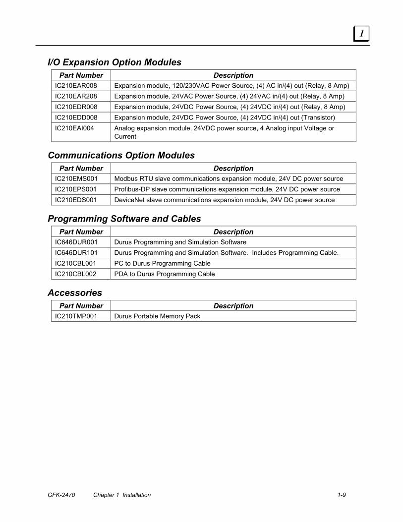
I/O Expansion Option Modules Part Number Description
IC210EAR008 Expansion module, 120/230VAC Power Source, (4) AC in/(4) out (Relay, 8 Amp) IC210EAR208 Expansion module, 24VAC Power Source, (4) 24VAC in/(4) out (Relay, 8 Amp) IC210EDR008 Expansion module, 24VDC Power Source, (4) 24VDC in/(4) out (Relay, 8 Amp) IC210EDD008 Expansion module, 24VDC Power Source, (4) 24VDC in/(4) out (Transistor) IC210EAI004 Analog expansion module, 24VDC power source, 4 Analog input Voltage or
Current
Communications Option Modules Part Number Description
IC210EMS001 Modbus RTU slave communications expansion module, 24V DC power source IC210EPS001 Profibus-DP slave communications expansion module, 24V DC power source IC210EDS001 DeviceNet slave communications expansion module, 24V DC power source
Programming Software and Cables Part Number Description
IC646DUR001 Durus Programming and Simulation Software IC646DUR101 Durus Programming and Simulation Software. Includes Programming Cable. IC210CBL001 PC to Durus Programming Cable IC210CBL002 PDA to Durus Programming Cable
Accessories Part Number Description
IC210TMP001 Durus Portable Memory Pack
1-10 DURUS Controllers System Manual – June 2007 GFK-2470
1
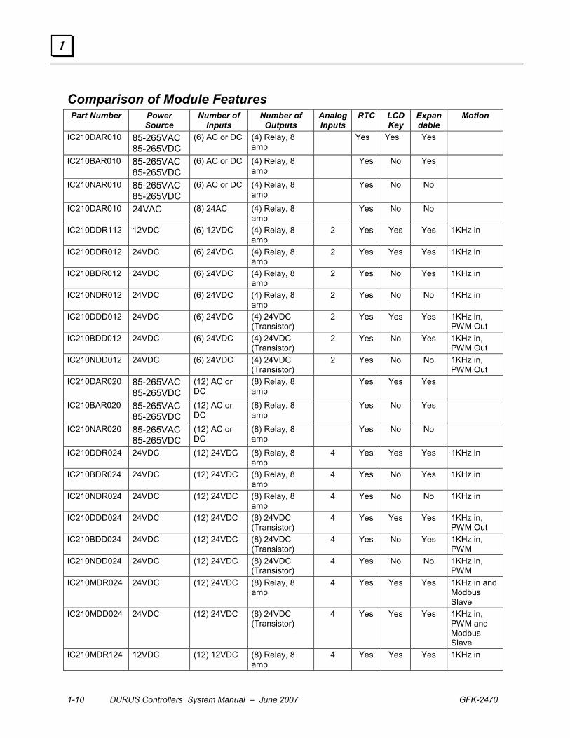
Comparison of Module Features Part Number Power
Source Number of
Inputs Number of
Outputs Analog Inputs
RTC LCD Key
Expandable
Motion
IC210DAR010 85-265VAC 85-265VDC
(6) AC or DC (4) Relay, 8 amp
Yes Yes Yes
IC210BAR010 85-265VAC 85-265VDC
(6) AC or DC (4) Relay, 8 amp
Yes No Yes
IC210NAR010 85-265VAC 85-265VDC
(6) AC or DC (4) Relay, 8 amp
Yes No No
IC210DAR010 24VAC (8) 24AC (4) Relay, 8 amp
Yes No No
IC210DDR112 12VDC (6) 12VDC (4) Relay, 8 amp
2 Yes Yes Yes 1KHz in
IC210DDR012 24VDC (6) 24VDC (4) Relay, 8 amp
2 Yes Yes Yes 1KHz in
IC210BDR012 24VDC (6) 24VDC (4) Relay, 8 amp
2 Yes No Yes 1KHz in
IC210NDR012 24VDC (6) 24VDC (4) Relay, 8 amp
2 Yes No No 1KHz in
IC210DDD012 24VDC (6) 24VDC (4) 24VDC (Transistor)
2 Yes Yes Yes 1KHz in, PWM Out
IC210BDD012 24VDC (6) 24VDC (4) 24VDC (Transistor)
2 Yes No Yes 1KHz in, PWM Out
IC210NDD012 24VDC (6) 24VDC (4) 24VDC (Transistor)
2 Yes No No 1KHz in, PWM Out
IC210DAR020 85-265VAC 85-265VDC
(12) AC or DC
(8) Relay, 8 amp
Yes Yes Yes
IC210BAR020 85-265VAC 85-265VDC
(12) AC or DC
(8) Relay, 8 amp
Yes No Yes
IC210NAR020 85-265VAC 85-265VDC
(12) AC or DC
(8) Relay, 8 amp
Yes No No
IC210DDR024 24VDC (12) 24VDC (8) Relay, 8 amp
4 Yes Yes Yes 1KHz in
IC210BDR024 24VDC (12) 24VDC (8) Relay, 8 amp
4 Yes No Yes 1KHz in
IC210NDR024 24VDC (12) 24VDC (8) Relay, 8 amp
4 Yes No No 1KHz in
IC210DDD024 24VDC (12) 24VDC (8) 24VDC (Transistor)
4 Yes Yes Yes 1KHz in, PWM Out
IC210BDD024 24VDC (12) 24VDC (8) 24VDC (Transistor)
4 Yes No Yes 1KHz in, PWM
IC210NDD024 24VDC (12) 24VDC (8) 24VDC (Transistor)
4 Yes No No 1KHz in, PWM
IC210MDR024 24VDC (12) 24VDC (8) Relay, 8 amp
4 Yes Yes Yes 1KHz in and Modbus Slave
IC210MDD024 24VDC (12) 24VDC (8) 24VDC (Transistor)
4 Yes Yes Yes 1KHz in, PWM and Modbus Slave
IC210MDR124 12VDC (12) 12VDC (8) Relay, 8 amp
4 Yes Yes Yes 1KHz in
GFK-2470 Chapter 1 Installation 1-11
1
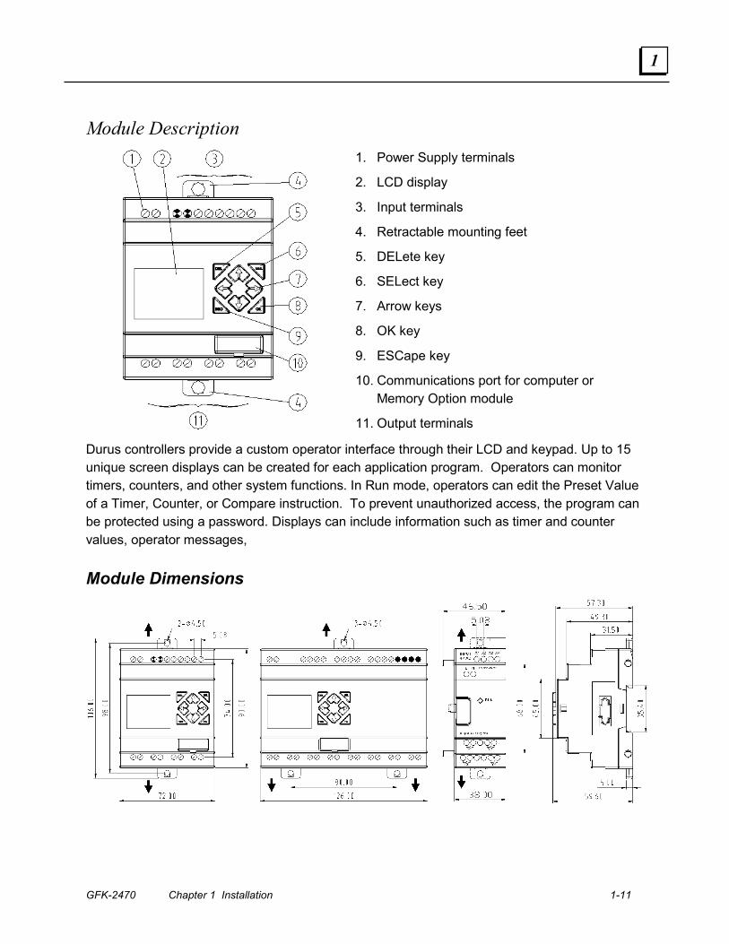
Module Description
1. Power Supply terminals
2. LCD display
3. Input terminals
4. Retractable mounting feet
5. DELete key
6. SELect key
7. Arrow keys
8. OK key
9. ESCape key
10. Communications port for computer or Memory Option module
11. Output terminals
Durus controllers provide a custom operator interface through their LCD and keypad. Up to 15 unique screen displays can be created for each application program. Operators can monitor timers, counters, and other system functions. In Run mode, operators can edit the Preset Value of a Timer, Counter, or Compare instruction. To prevent unauthorized access, the program can be protected using a password. Displays can include information such as timer and counter values, operator messages,
Module Dimensions
1-12 DURUS Controllers System Manual – June 2007 GFK-2470
1
Programming Features Programs can be created using the programming software or directly in the controller, using the keypad and LCD.
Programming Formats Durus Controllers provide two different programming formats, ladder logic and block diagram.
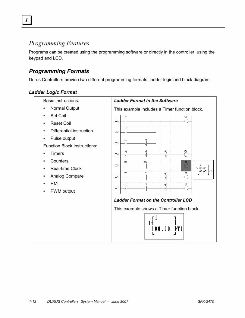
Ladder Logic Format Basic Instructions:
▪ Normal Output
▪ Set Coil
▪ Reset Coil
▪ Differential instruction
▪ Pulse output
Function Block Instructions:
▪ Timers
▪ Counters
▪ Real-time Clock
▪ Analog Compare
▪ HMI
▪ PWM output
Ladder Format in the Software
This example includes a Timer function block.
Ladder Format on the Controller LCD
This example shows a Timer function block.
GFK-2470 Chapter 1 Installation 1-13
1
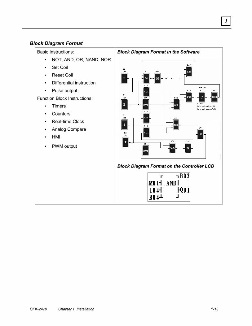
Block Diagram Format Basic Instructions:
▪ NOT, AND, OR, NAND, NOR
▪ Set Coil
▪ Reset Coil
▪ Differential instruction
▪ Pulse output
Function Block Instructions:
▪ Timers
▪ Counters
▪ Real-time Clock
▪ Analog Compare
▪ HMI
▪ PWM output
Block Diagram Format in the Software
Block Diagram Format on the Controller LCD

1-14 DURUS Controllers System Manual – June 2007 GFK-2470
1
Program Transfer Programs can be easily stored and transferred between modules using the optional Memory Pack. The same controller port can also be used for a cable connection to a computer RS-232 port (IC210TMP001).
Controller and Memory Pack Controller with RS-232 Cable

GFK-2470 Chapter 1 Installation 1-15
1
Communications Features Durus controllers provide the communications features listed below.
MODBUS RTU A Durus controller can communicate with a controller or other device via a MODBUS RTU Slave Communications Expansion Module, 24VDC (IC210EMS001). Chapter 8 describes the MODBUS RTU features provided by this module.
Profibus-DP Chapter 9 This chapter describes the Profibus-DP features that can be incorporated into a Durus controller system by including a Profibus-DP Slave Communications Expansion Module, 24VDC (IC210EPS001).
The Profibus-DP Slave Communications Expansion Module, 24VDC (IC210EPS001) always operates as network slave (2 below).
The GSD file can set up five different operating “modules”:
Read / write 14 bytes: Status of all coils, Run/Stop status of controller, function block values Read 7 bytes: Coils (I, X, Q, Y) Read 2 bytes : Coils (M) Write 2 bytes: Coils (M) Write 3 bytes: Coils (Q, Y)
DeviceNet Chapter 10 describes the DeviceNet features that can be incorporated into a Durus controller system by including a DeviceNet Slave Communications Expansion Module, 24VDC (IC210EDS001).
The DeviceNet Slave Communications Expansion Module operates as a DeviceNet Group II Only Slave device, interfacing the Durus controller to a DeviceNet communications bus. If a DeviceNet Communications Expansion Module is installed in the controller, it must be the only communications module present.

1-16 DURUS Controllers System Manual – June 2007 GFK-2470
1
Data Link and Remote I/O The Datalink function on Durus controller models IC210MDR024 and IC210MDD024 uses MODBUS protocol to connect up to eight additional units of the same type as independent slaves. Each slave has its own application logic program and I/O.
W Memory 1 8 9 16 57 64
ID =0 ID =1 ID =7
Each controller on the Datalink network writes 8 bits of data to a specific area of W memory. Each controller can read the W memory areas of other controllers on the Datalink network.
Remote I/O In Remote I/O Mode, two controllers of the same type can be linked as a master and slave. The inputs of the slave are mapped to the X (expansion) inputs of the master, and the outputs of the slave are mapped to the Y (expansion) outputs of the master. The modules are connected via their RS-485 terminals, and exchange data using MODBUS RTU protocol. No application programming is needed to transfer the data. In this type of system, the slave controller module does not run an application program. It is controlled by the application program in the master.
Master Slave
Coil Type L 1 (L1 is assigned to Node ID 0 being programmed) L2 to L8 (Address of remote Nodes ID 1 to ID 7)
Function Mode 1 for Send (Broadcast out from ID 0) 2 for Receive (Receive from other Nodes (ID 1 to ID 7)
Coil Number I01 – 08, X01 – 08, Q01 – 08, Y01 – 08, M01 - 08
Select Address (Number of bits to be masked)
1 to 8
From (Node data) W01 to W64 To (Mapped data from Node)
I01 – 08, X01 – 08, Q01 – 08, Y01 – 08, M01 - 08
GFK-2470 2-1
Installation
This chapter describes the basic installation steps for Durus controller modules;
▪ Installation Environment
▪ Mounting Instructions
▪ Field Wiring
▪ I/O Link or Remote I/O Wiring
▪ Transferring Application Programs
▪ Inspection and Maintenance
2 Chapter

2-2 DURUS Controllers System Manual – June 2007 GFK-2470
2
Installation Environment Modules must not be installed under conditions of:
▪ Ambient temperature above 0-55 degrees Celsius.
▪ Relative humidity outside the range 5-90%.
▪ Excessive dust, salt and iron powder.
▪ Direct sunshine.
▪ The environment is subject to frequent vibration and impact.
▪ The area contains erosive and inflammable gases susceptible to fire.
▪ The area is abundant of volatile oil gas, organic solvent, ammonia, electrolytic gas.
▪ Poor ventilation or close to heating source.
Installation in Hazardous Locations ▪ EQUIPMENT LABELED WITH REFERENCE TO CLASS I, GROUPS A, B, C & D, DIV. 2
HAZARDOUS LOCATIONS IS SUITABLE FOR USE IN CLASS I, DIVISION 2, GROUPS A, B, C, D OR NON-HAZARDOUS LOCATIONS ONLY
▪ WARNING - EXPLOSION HAZARD - SUBSTITUTION OF COMPONENTS MAY IMPAIR SUITABILITY FOR CLASS I, DIVISION 2;
▪ WARNING - EXPLOSION HAZARD - WHEN IN HAZARDOUS LOCATIONS, TURN OFF POWER BEFORE REPLACING OR WIRING MODULES; AND
▪ WARNING - EXPLOSION HAZARD - DO NOT DISCONNECT EQUIPMENT UNLESS POWER HAS BEEN SWITCHED OFF OR THE AREA IS KNOWN TO BE NONHAZARDOUS.
External Protection Devices The following external protection device should be installed:
▪ Emergency-Stop circuit
▪ Protection circuit
▪ Operation circuit for high-voltage components
GFK-2470 Chapter 2 Installation 2-3
2
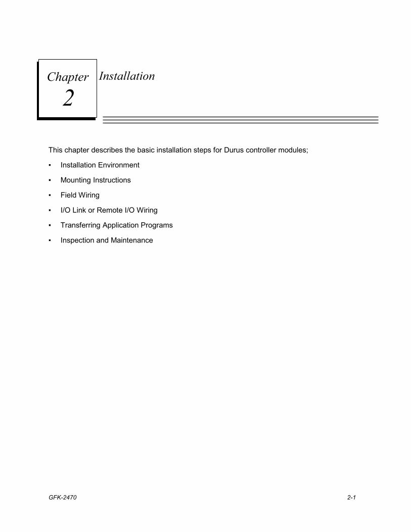
Mounting Instructions DURUS modules can be mounted on a DIN rail, or panel-mounted for greater resistance to mechanical vibration and shock. Modules must be mounted in an upright position on a vertical surface or horizontal DIN rail. The diagrams below show correct mounting orientation. Modules must not be mounted on a horizontal surface or in a rotated orientation.
2-4 DURUS Controllers System Manual – June 2007 GFK-2470
2
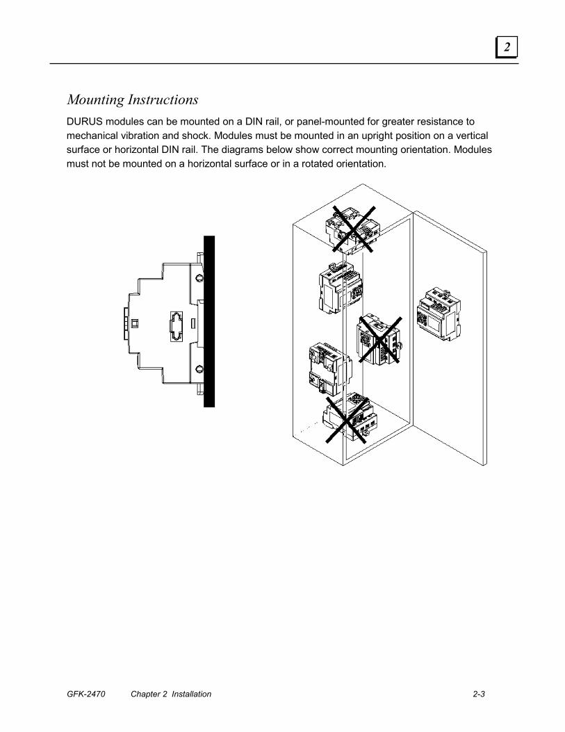
Panel Mounting For panel mounting, extend the module’s retractable mounting tabs and use M4 screws to mount the unit on the panel as shown below.
Connecting An Expansion Module To connect an expansion module (with the expansion connector installed), (1) press the latch on the Expansion module and (2) plug it into the master module as shown below. (3) Mount the Expansion unit on the panel with two screws.
Q1
DC 24V Input 8 x DC(A1,A2 0 ~ 10V)
Output 4 x Relay / 8A
+ AC 100~240V
Q4 Q3 Q2 Y3 Y4
Y2Y1
Output 4 x Relay / 8A
A2 A1 I5 I4 I6 I1 I2 - I3 X4X3X1 X2
Run
NL
Input 4×AC
Latch
Connector
GFK-2470 Chapter 2 Installation 2-5
2
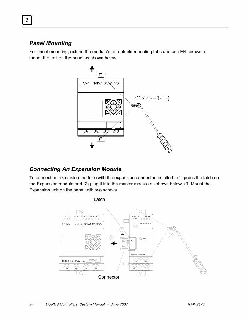
DIN Rail Installation DURUS controllers and expansion modules snap easily onto a DIN rail. With the retractable mounting tabs pushed in: (1) Place the module over the DIN rail so that the upper mounting tab hooks behind the rail. (2) Pivot the module downward until it clicks into place, with the lower tab(s) secured around the rail.
To remove a module from the DIN rail: (1) pull out the retractable mounting tab(s) to release the DIN rail, and (2) pull the module away from the rail.
To add an expansion module (with the expansion connector installed), press the latch on the expansion module and slide it on the DIN rail to connect it to the master unit.
Q2 Q1
Output 4 x Relay / 8A
Q4Q3
DC 24V Input 8 x DC(A1,A2 0 ~10V)
I3 I4 I2 I1 - + A2I6 A1I5
Y4Y3
Y2Y1
AC 100~240V NL
Output 4 x Relay / 8A
Run
X3X2X1 X4 Input 4×AC
Connector
DIN Rail
Latch
Removing Module from a DIN Rail Installing Module on a DIN Rail
2-6 DURUS Controllers System Manual – June 2007 GFK-2470
2
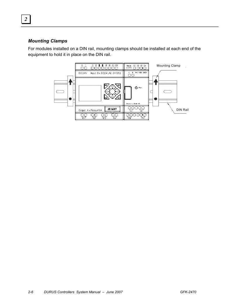
Mounting Clamps For modules installed on a DIN rail, mounting clamps should be installed at each end of the equipment to hold it in place on the DIN rail.
Mounting Clamp
DIN Rail
GFK-2470 Chapter 2 Installation 2-7
2
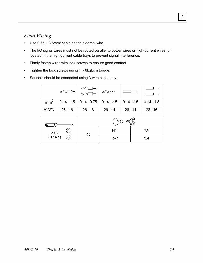
Field Wiring ▪ Use 0.75 ~ 3.5mm2 cable as the external wire.
▪ The I/O signal wires must not be routed parallel to power wires or high-current wires, or located in the high-current cable trays to prevent signal interference.
▪ Firmly fasten wires with lock screws to ensure good contact
▪ Tighten the lock screws using 4 ~ 6kgf.cm torque.
▪ Sensors should be connected using 3-wire cable only.
2-8 DURUS Controllers System Manual – June 2007 GFK-2470
2
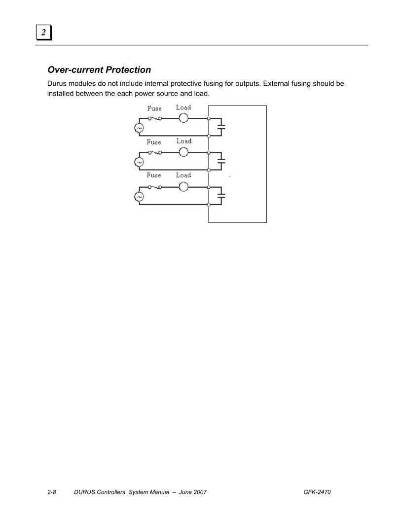
Over-current Protection Durus modules do not include internal protective fusing for outputs. External fusing should be installed between the each power source and load.

GFK-2470 Chapter 2 Installation 2-9
2
Field Wiring for 12-Point and 20-Point, 12/24VDC Input Modules
(1) Fuse (2A)
(2) Surge absorber (36V DC)
Sensor Wiring Use 3-wire, PNP only.
2-10 DURUS Controllers System Manual – June 2007 GFK-2470
2
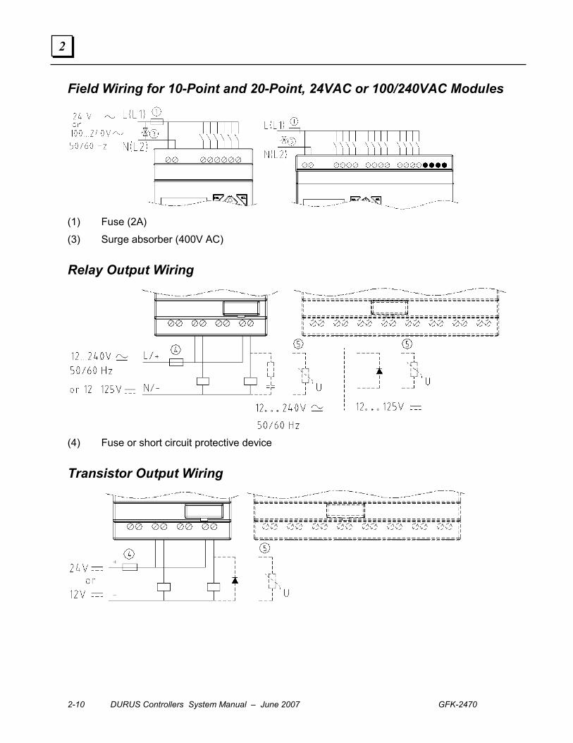
Field Wiring for 10-Point and 20-Point, 24VAC or 100/240VAC Modules
(1) Fuse (2A)
(3) Surge absorber (400V AC)
Relay Output Wiring
(4) Fuse or short circuit protective device
Transistor Output Wiring
GFK-2470 Chapter 2 Installation 2-11
2
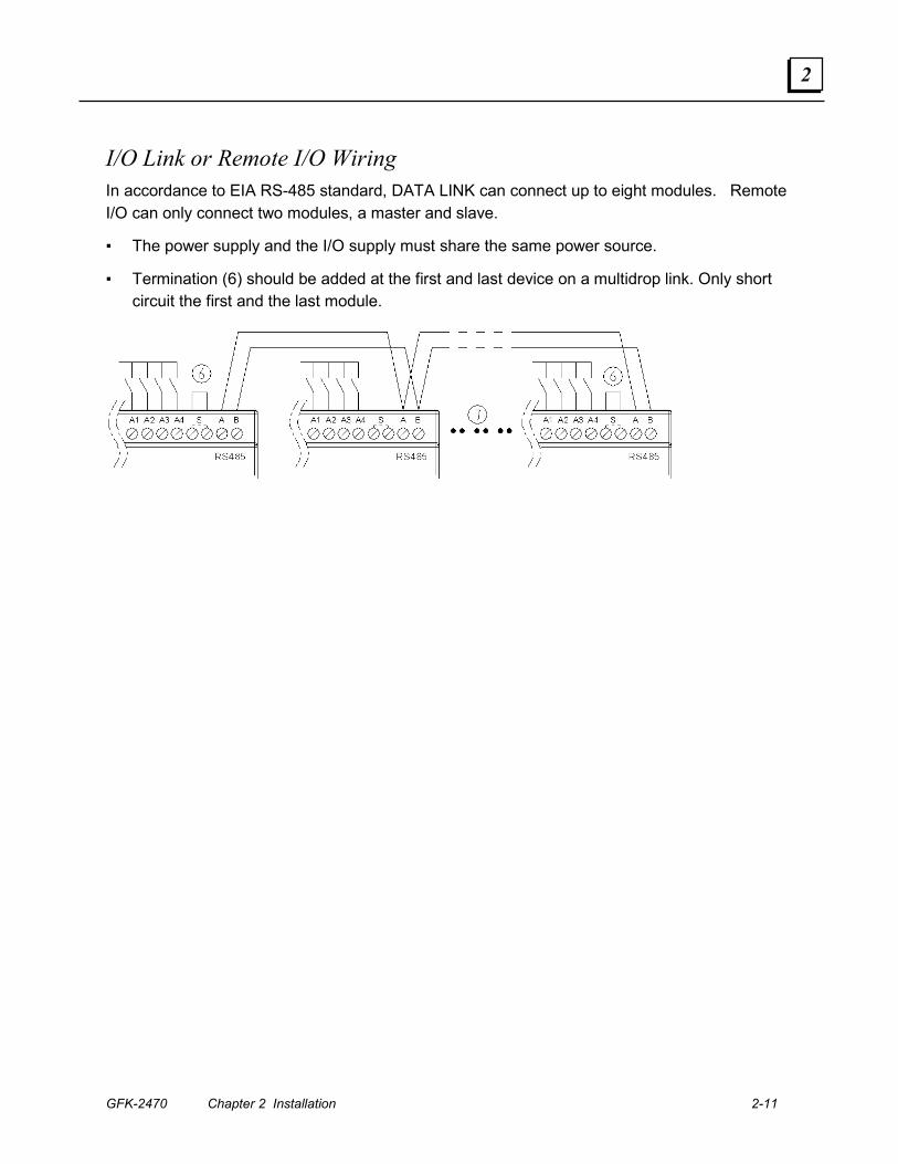
I/O Link or Remote I/O Wiring In accordance to EIA RS-485 standard, DATA LINK can connect up to eight modules. Remote I/O can only connect two modules, a master and slave.
▪ The power supply and the I/O supply must share the same power source.
▪ Termination (6) should be added at the first and last device on a multidrop link. Only short circuit the first and the last module.
2-12 DURUS Controllers System Manual – June 2007 GFK-2470
2
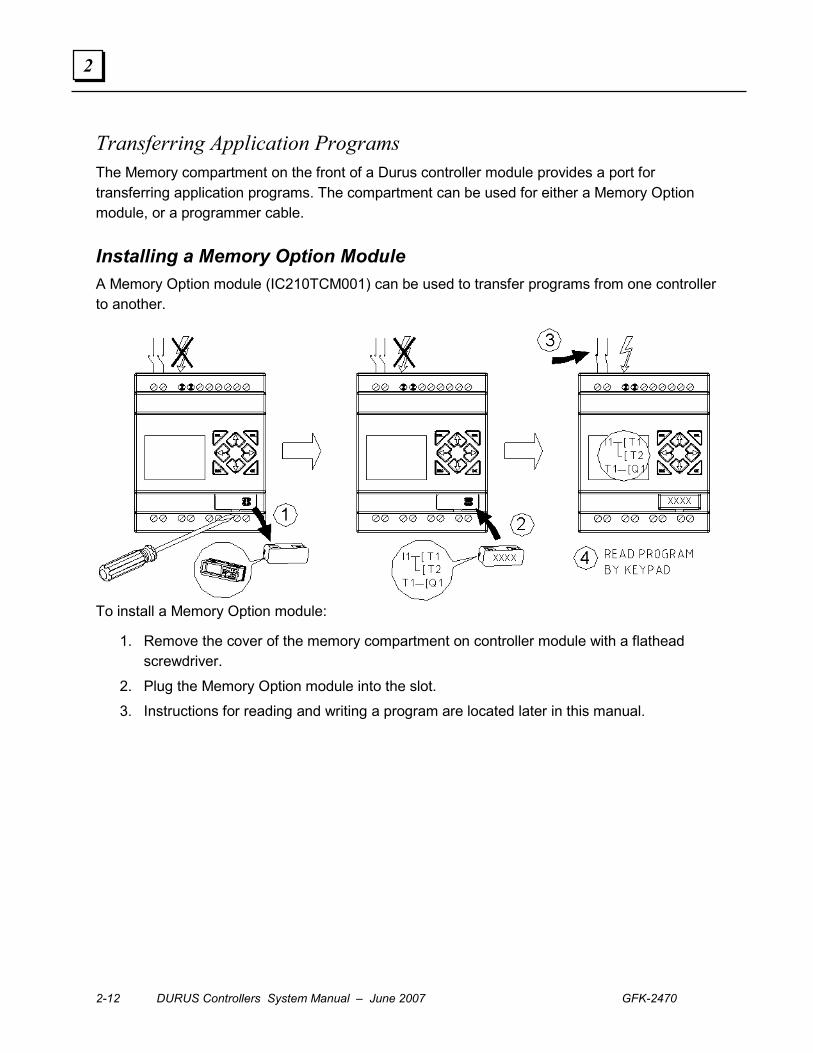
Transferring Application Programs The Memory compartment on the front of a Durus controller module provides a port for transferring application programs. The compartment can be used for either a Memory Option module, or a programmer cable.
Installing a Memory Option Module A Memory Option module (IC210TCM001) can be used to transfer programs from one controller to another.
To install a Memory Option module:
1. Remove the cover of the memory compartment on controller module with a flathead screwdriver.
2. Plug the Memory Option module into the slot.
3. Instructions for reading and writing a program are located later in this manual.
GFK-2470 Chapter 2 Installation 2-13
2
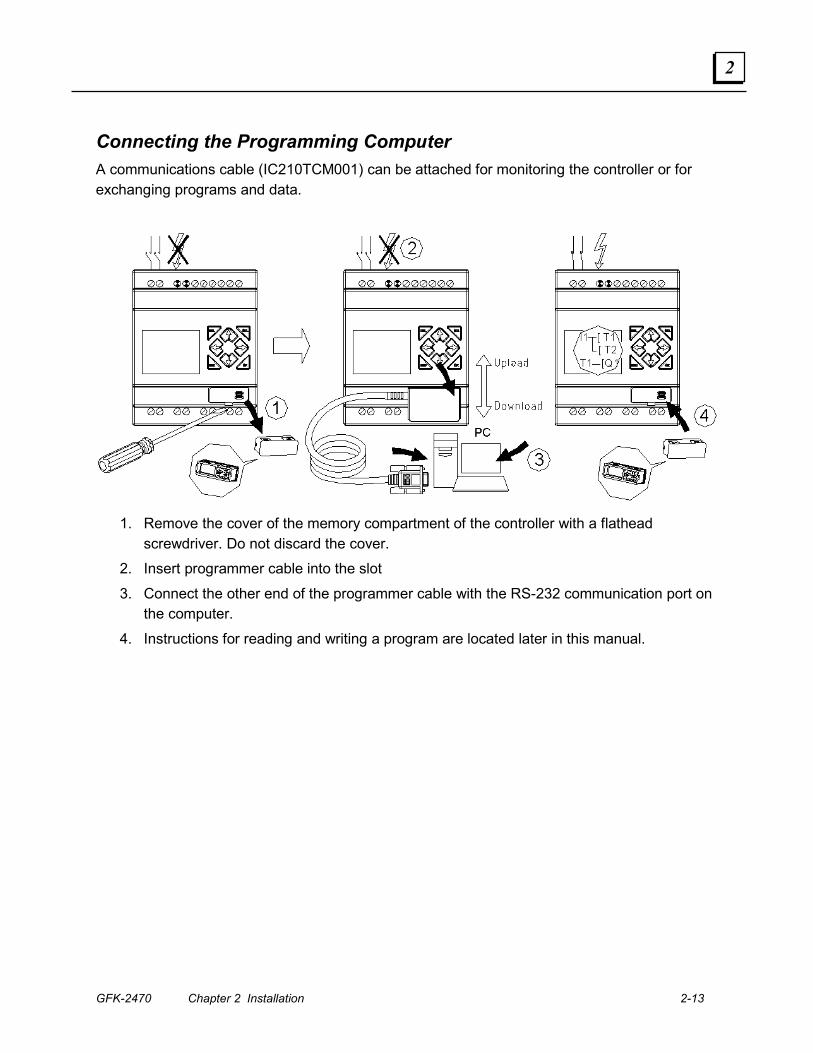
Connecting the Programming Computer A communications cable (IC210TCM001) can be attached for monitoring the controller or for exchanging programs and data.
1. Remove the cover of the memory compartment of the controller with a flathead screwdriver. Do not discard the cover.
2. Insert programmer cable into the slot
3. Connect the other end of the programmer cable with the RS-232 communication port on the computer.
4. Instructions for reading and writing a program are located later in this manual.
2-14 DURUS Controllers System Manual – June 2007 GFK-2470
2
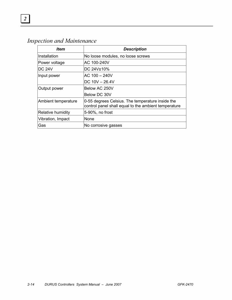
Inspection and Maintenance Item Description
Installation No loose modules, no loose screws Power voltage AC 100-240V DC 24V DC 24V±10% Input power AC 100 – 240V
DC 10V – 26.4V Output power Below AC 250V
Below DC 30V Ambient temperature 0-55 degrees Celsius. The temperature inside the
control panel shall equal to the ambient temperature Relative humidity 5-90%, no frost Vibration, Impact None Gas No corrosive gasses

GFK-2470 3-1
Function Blocks
This chapter describes the Function Blocks that can be included in both ladder logic and
block diagram application programs for a DURUS Micro PLC.
▪ Memory in the Controller
▪ Counters
▪ Timers
▪ Real-Time Clock Instructions
▪ Compare Functions
▪ PWM Output Instruction
▪ HMI Instructions
▪ Datalink Function
Chapter
3
3-2 DURUS Controllers System Manual – June 2007 GFK-2470
3
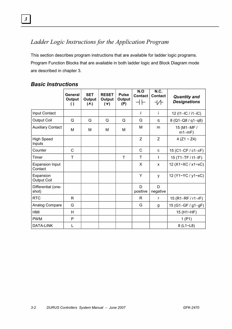
Ladder Logic Instructions for the Application Program
This section describes program instructions that are available for ladder logic programs.
Program Function Blocks that are available in both ladder logic and Block Diagram mode
are described in chapter 3.
Basic Instructions
General Output
( )
SET Output
(����)
RESET Output
(����)
Pulse Output
(P)
N.O Contact
N.C. Contact
Quantity and Designations
Input Contact I i 12 (I1∼IC / i1∼iC)
Output Coil Q Q Q Q Q q 8 (Q1∼Q8 / q1∼q8)
Auxiliary Contact M M M M M m 15 (M1∼MF / m1∼mF)
High Speed Inputs Z Z 4 (Z1 ~ Z4)
Counter C C c 15 (C1∼CF / c1∼cF)
Timer T T T t 15 (T1∼TF / t1∼tF)
Expansion Input Contact X x 12 (X1~XC / x1~xC)
Expansion Output Coil Y y 12 (Y1~YC / y1~xC)
Differential (one-shot) D
positiveD
negative
RTC R R r 15 (R1∼RF / r1∼rF)
Analog Compare G G g 15 (G1∼GF / g1∼gF)
HMI H 15 (H1~HF)
PWM P 1 (P1)
DATA-LINK L 8 (L1~L8)
GFK-2470 Chapter 3 Function Blocks 3-3
3
Memory in the Controller
I Memory: The controller assigns digital inputs to I (input) memory. The number of digital
inputs available (6, 8, or 12) depends on the controller model.
Q Memory: Digital outputs are assigned to Q memory. Depending on the controller
model, either 4 or 8 digital output points are available.
M Memory: Auxiliary relays are assigned to M memory. Auxiliary relays are internal bits
that can be used in programs as either inputs or outputs. They do not represent actual
input or output devices.
T Memory: Timer Status Bits are assigned to T memory. Each Timer Status Bit shows the
relationship between the timer’s Preset Value and its Current Value. A Timer Status bit is
set to 1 when the Current Value is equal to or greater than the Preset Value.
C Memory: Counter Status Bits are assigned to C memory. Each Counter Status Bit
shows the relationship between the counter’s Preset Value and its Current Value. A
Counter Status bit is set to 1 when the Current Value is equal to or greater than the Preset
Value.
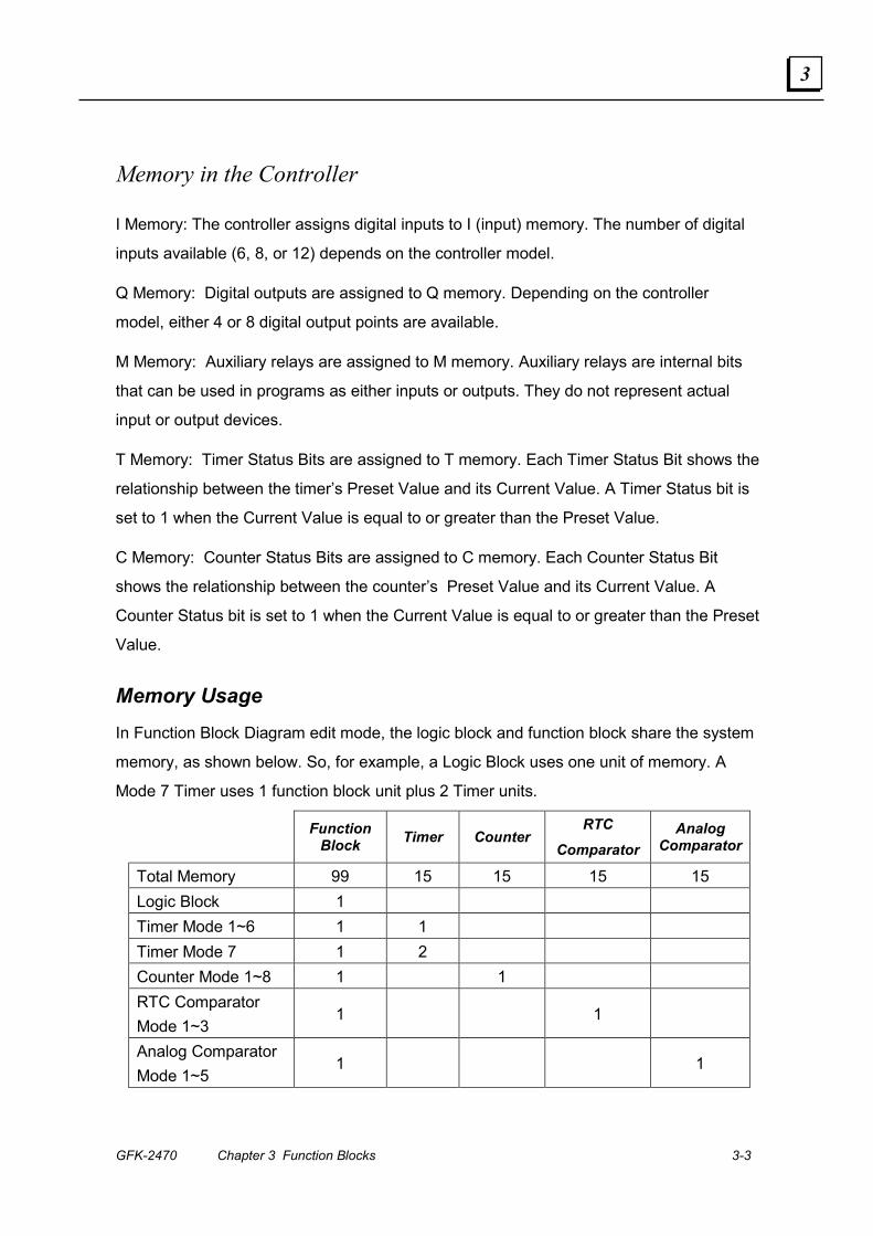
Memory Usage In Function Block Diagram edit mode, the logic block and function block share the system
memory, as shown below. So, for example, a Logic Block uses one unit of memory. A
Mode 7 Timer uses 1 function block unit plus 2 Timer units.
Function Block Timer Counter
RTC Comparator
Analog Comparator
Total Memory 99 15 15 15 15 Logic Block 1 Timer Mode 1~6 1 1 Timer Mode 7 1 2 Counter Mode 1~8 1 1 RTC Comparator Mode 1~3
1 1
Analog Comparator Mode 1~5
1 1
3-4 DURUS Controllers System Manual – June 2007 GFK-2470
3
Example Memory Usage When the Function Block Diagram program contains:
2 AND Logic Blocks
1 OR Logic Block
2 Timers Mode 1
1 Counter Mode
1 RTC Comparator mode 1 Function Block
The total Function Blocks used are 2+1+2+1+1=7. The remainder is 99 (total memory) –7
(Function Blocks) = 92.
The timers used are 2 (Function Blocks) + 2 (Timers ) = 4. The remainder is 15 (total
timers) – 4 = 11.
The counter used is 1, and the remainder is 15 (total timers) –1 = 14.
The RTC comparator used is 1, and the remainder is 15 - 1=14.
The analog comparator is unused, so the remainder is 15.
GFK-2470 Chapter 3 Function Blocks 3-5
3
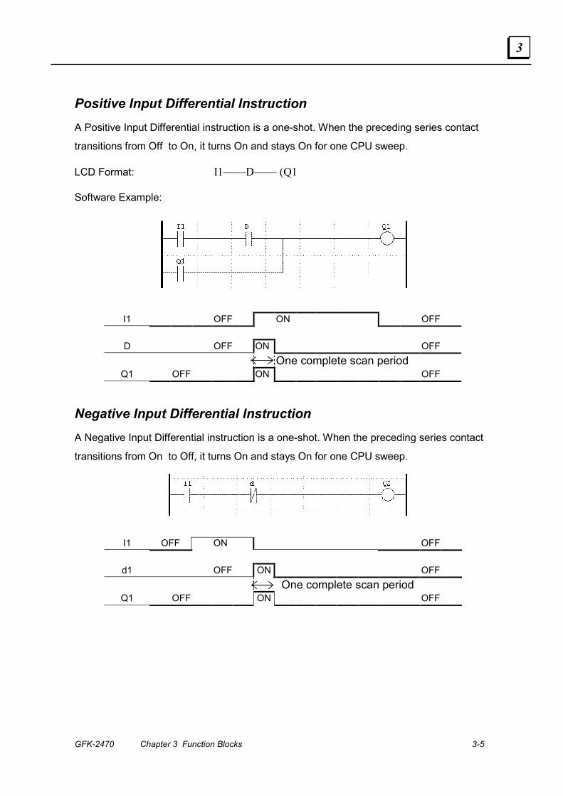
Positive Input Differential Instruction A Positive Input Differential instruction is a one-shot. When the preceding series contact
transitions from Off to On, it turns On and stays On for one CPU sweep.
LCD Format: I1——D—— (Q1
Software Example:
I1 OFF ON OFF
D OFF ON OFF
One complete scan period Q1 OFF ON OFF
Negative Input Differential Instruction A Negative Input Differential instruction is a one-shot. When the preceding series contact
transitions from On to Off, it turns On and stays On for one CPU sweep.
I1 OFF ON OFF
d1 OFF ON OFF One complete scan period
Q1 OFF ON OFF

3-6 DURUS Controllers System Manual – June 2007 GFK-2470
3
Normal Output A Normal output turns On when the preceding input goes On.
LCD Format: I1———— (Q1
Software Example:
I1 OFF ON OFF
Q1 OFF ON OFF
SET Output (Latch) A Set Output turns on either an output (Q) or auxiliary (M) coil when the preceding input
contact transitions from Off to On. The output remains On (set) even if the preceding input
contact goes Off. It remains On until it is set to 0 using a Reset instruction.
LCD Format: I1———— ↑Q1
Software Example:
I1 OFF ON OFF
Q1 OFF ON
GFK-2470 Chapter 3 Function Blocks 3-7
3
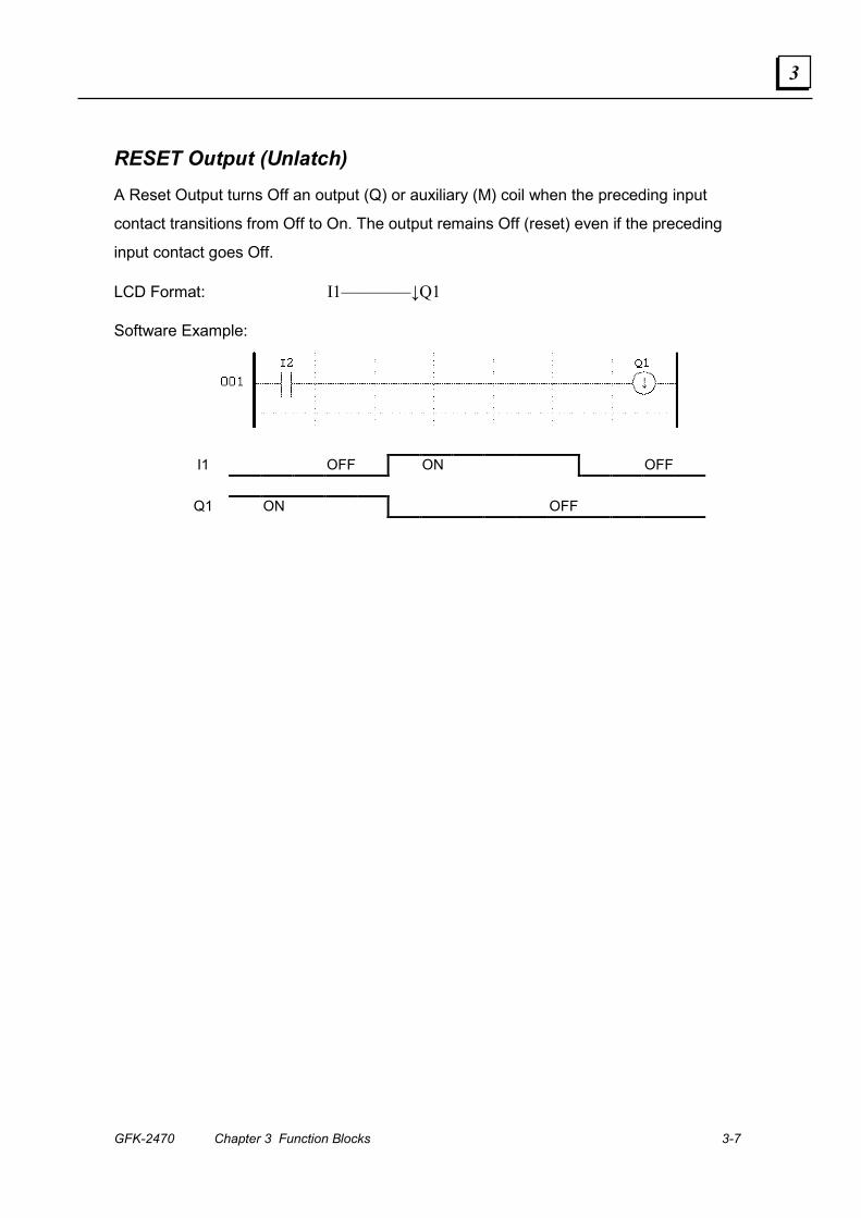
RESET Output (Unlatch) A Reset Output turns Off an output (Q) or auxiliary (M) coil when the preceding input
contact transitions from Off to On. The output remains Off (reset) even if the preceding
input contact goes Off.
LCD Format: I1————↓Q1
Software Example:
I1 OFF ON OFF
Q1 ON OFF
3-8 DURUS Controllers System Manual – June 2007 GFK-2470
3
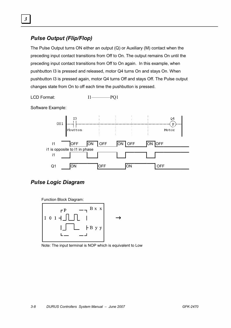
Pulse Output (Flip/Flop) The Pulse Output turns ON either an output (Q) or Auxiliary (M) contact when the
preceding input contact transitions from Off to On. The output remains On until the
preceding input contact transitions from Off to On again. In this example, when
pushbutton I3 is pressed and released, motor Q4 turns On and stays On. When
pushbutton I3 is pressed again, motor Q4 turns Off and stays Off. The Pulse output
changes state from On to off each time the pushbutton is pressed.
LCD Format: I1————PQ1
Software Example:
I1 OFF ON OFF ON OFF ON OFF
i1 is opposite to I1 in phase i1
Q1 ON OFF ON OFF
Pulse Logic Diagram
Function Block Diagram:
→→→→
Note: The input terminal is NOP which is equivalent to Low
GFK-2470 Chapter 3 Function Blocks 3-9
3
Counters
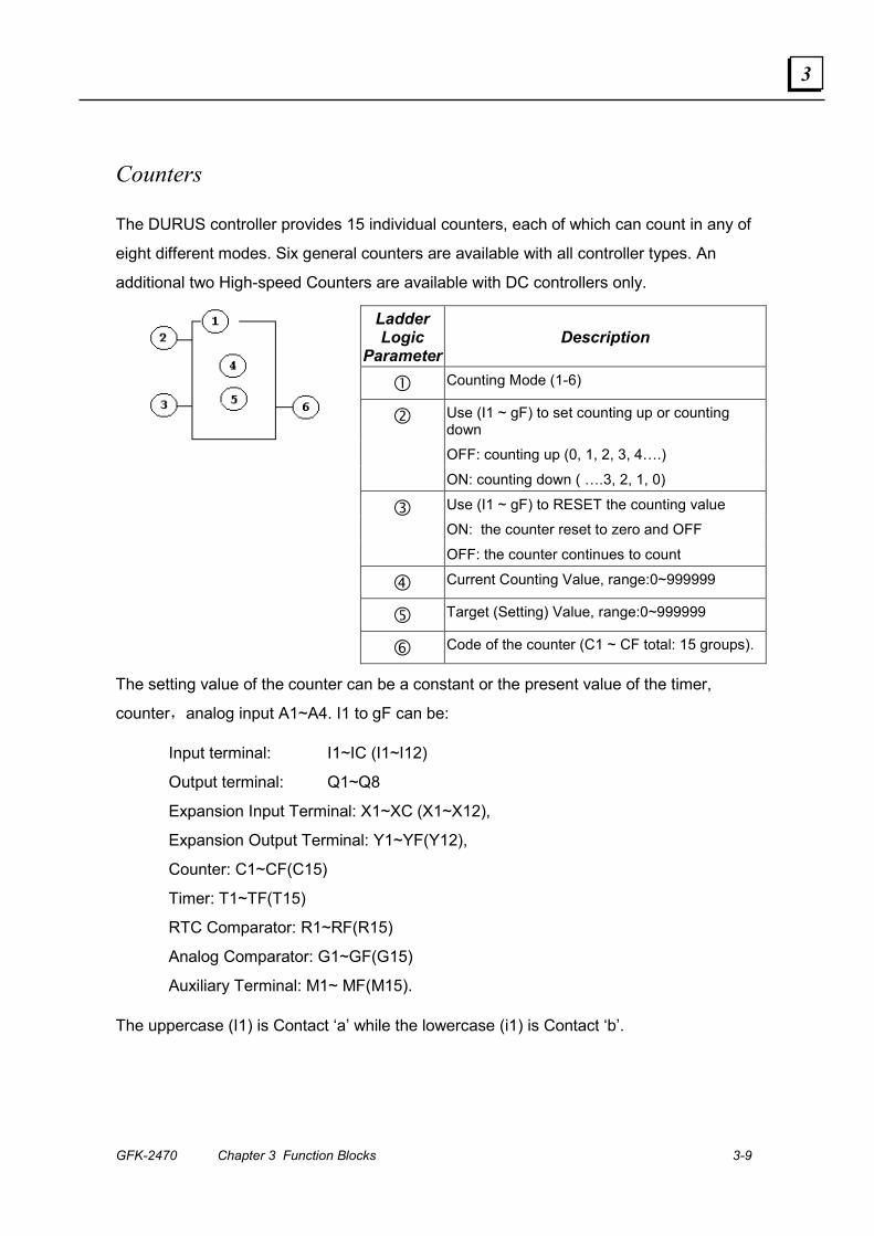
The DURUS controller provides 15 individual counters, each of which can count in any of
eight different modes. Six general counters are available with all controller types. An
additional two High-speed Counters are available with DC controllers only.
Ladder Logic
ParameterDescription
� Counting Mode (1-6)
Use (I1 ~ gF) to set counting up or counting down
OFF: counting up (0, 1, 2, 3, 4….)
�
ON: counting down ( ….3, 2, 1, 0)
Use (I1 ~ gF) to RESET the counting value
ON: the counter reset to zero and OFF �
OFF: the counter continues to count
� Current Counting Value, range:0~999999
� Target (Setting) Value, range:0~999999
� Code of the counter (C1 ~ CF total: 15 groups).
The setting value of the counter can be a constant or the present value of the timer,
counter,analog input A1~A4. I1 to gF can be:
Input terminal: I1~IC (I1~I12)
Output terminal: Q1~Q8
Expansion Input Terminal: X1~XC (X1~X12),
Expansion Output Terminal: Y1~YF(Y12),
Counter: C1~CF(C15)
Timer: T1~TF(T15)
RTC Comparator: R1~RF(R15)
Analog Comparator: G1~GF(G15)
Auxiliary Terminal: M1~ MF(M15).
The uppercase (I1) is Contact ‘a’ while the lowercase (i1) is Contact ‘b’.

3-10 DURUS Controllers System Manual – June 2007 GFK-2470
3
Counter Mode 1: Count Up or Down to Preset, Non-Retentive Counter Mode 1 counts either up from zero to a Preset Value or down from the Preset
Value to zero, and then stops. The rising edge produces count pulses. If the count
direction is Up, the output is On when the Current Value is equal to the Target Value and
a reset sets the counter to zero. If the count direction is Down, the output is on when the
Current Value is equal to zero and a reset sets the Current Value to the Target Value. The
Current Value is non-retentive. It resets when the controller loses power.
Timing Diagram
Block Diagram Example
LCD Example for Counter Mode 1
Counting Input →→→→ Up/Down Counting →→→→
Reset →→→→ Counting Parameter →→→→
GFK-2470 Chapter 3 Function Blocks 3-11
3
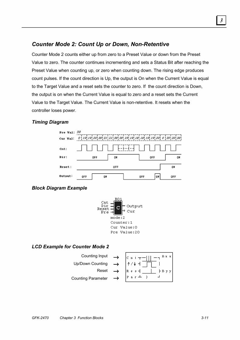
Counter Mode 2: Count Up or Down, Non-Retentive Counter Mode 2 counts either up from zero to a Preset Value or down from the Preset
Value to zero. The counter continues incrementing and sets a Status Bit after reaching the
Preset Value when counting up, or zero when counting down. The rising edge produces
count pulses. If the count direction is Up, the output is On when the Current Value is equal
to the Target Value and a reset sets the counter to zero. If the count direction is Down,
the output is on when the Current Value is equal to zero and a reset sets the Current
Value to the Target Value. The Current Value is non-retentive. It resets when the
controller loses power.
Timing Diagram
Block Diagram Example
LCD Example for Counter Mode 2
Counting Input →→→→ Up/Down Counting →→→→
Reset →→→→
Counting Parameter →→→→
3-12 DURUS Controllers System Manual – June 2007 GFK-2470
3
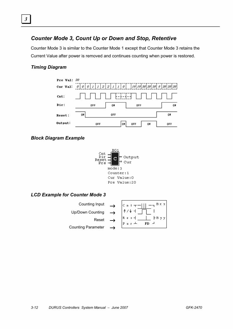
Counter Mode 3, Count Up or Down and Stop, Retentive Counter Mode 3 is similar to the Counter Mode 1 except that Counter Mode 3 retains the
Current Value after power is removed and continues counting when power is restored.
Timing Diagram
Block Diagram Example
LCD Example for Counter Mode 3
Counting Input →→→→ Up/Down Counting →→→→
Reset →→→→
Counting Parameter →→→→
GFK-2470 Chapter 3 Function Blocks 3-13
3
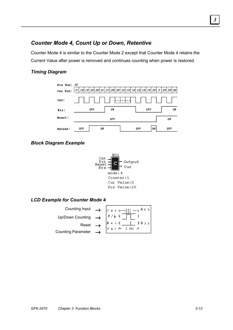
Counter Mode 4, Count Up or Down, Retentive Counter Mode 4 is similar to the Counter Mode 2 except that Counter Mode 4 retains the
Current Value after power is removed and continues counting when power is restored.
Timing Diagram
Block Diagram Example
LCD Example for Counter Mode 4
Counting Input →→→→
Up/Down Counting →→→→
Reset →→→→
Counting Parameter →→→→
3-14 DURUS Controllers System Manual – June 2007 GFK-2470
3
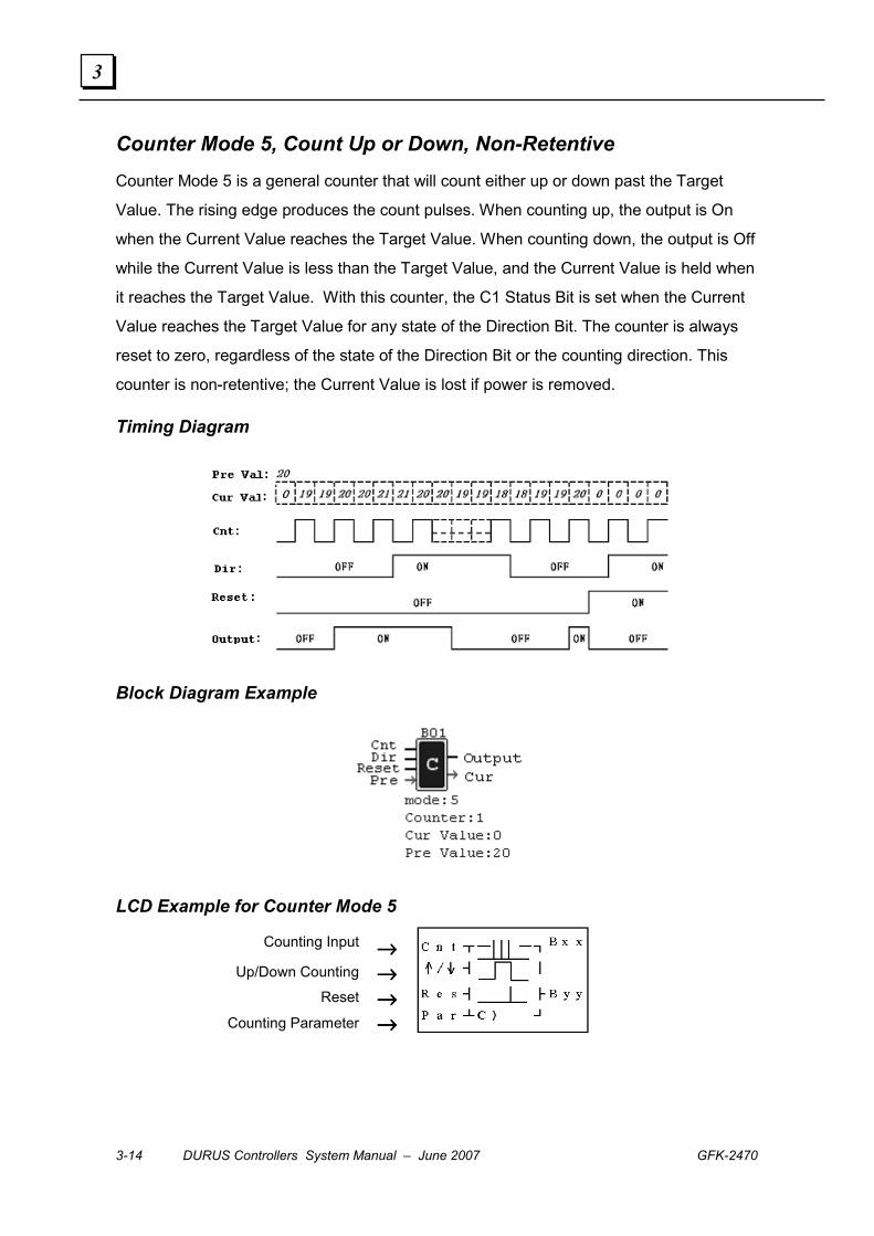
Counter Mode 5, Count Up or Down, Non-Retentive Counter Mode 5 is a general counter that will count either up or down past the Target
Value. The rising edge produces the count pulses. When counting up, the output is On
when the Current Value reaches the Target Value. When counting down, the output is Off
while the Current Value is less than the Target Value, and the Current Value is held when
it reaches the Target Value. With this counter, the C1 Status Bit is set when the Current
Value reaches the Target Value for any state of the Direction Bit. The counter is always
reset to zero, regardless of the state of the Direction Bit or the counting direction. This
counter is non-retentive; the Current Value is lost if power is removed.
Timing Diagram
Block Diagram Example
LCD Example for Counter Mode 5
Counting Input →→→→ Up/Down Counting →→→→
Reset →→→→ Counting Parameter →→→→
GFK-2470 Chapter 3 Function Blocks 3-15
3
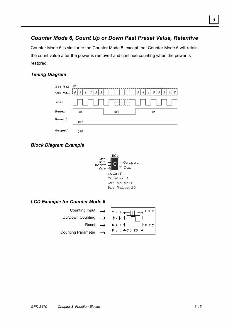
Counter Mode 6, Count Up or Down Past Preset Value, Retentive Counter Mode 6 is similar to the Counter Mode 5, except that Counter Mode 6 will retain
the count value after the power is removed and continue counting when the power is
restored.
Timing Diagram
Block Diagram Example
LCD Example for Counter Mode 6
Counting Input →→→→ Up/Down Counting →→→→
Reset →→→→
Counting Parameter →→→→

3-16 DURUS Controllers System Manual – June 2007 GFK-2470
3
High-Speed Counter (Only on DC Power Supply Models) DC power supply modules have two 1 KHz High-speed input terminals, I1 and I2. These
inputs can be used as either DC inputs or as High-Speed Counter inputs connected to an
input device such as an encoder.
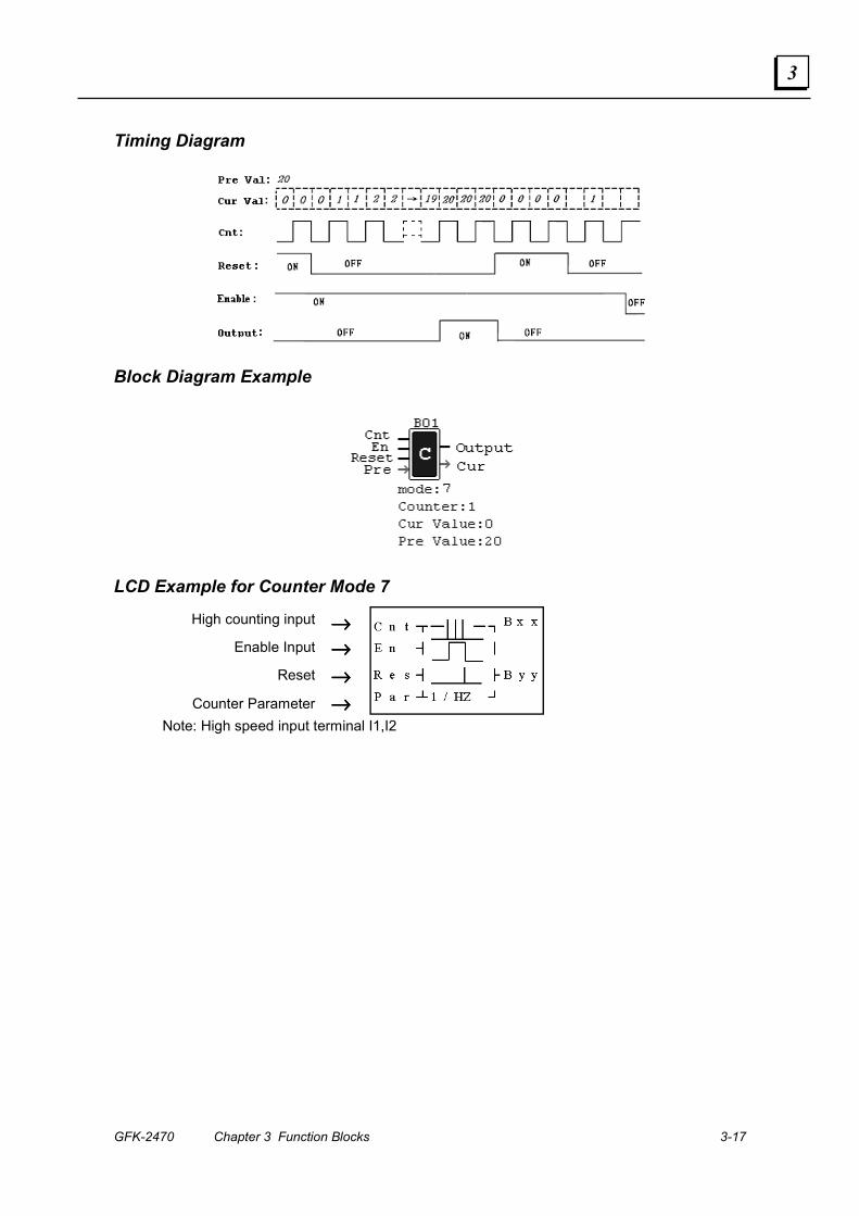
Counter Mode 7, Count Up to Target Value Counter Mode 7 is a High-Speed Up Counter that operates at speeds up to 1KHz at
24VDC. The coil (C1-CF) that is specified by parameter 6 will turn On when the count
reaches the Preset Value (parameter 5), and remain On. The counter is reset when either
the Reset input (parameter 3) is active, or when the preceding ladder logic rung is
inactive.
Parameter Description
� Counting mode(7)—high speed counting
� High speed counting input terminal: only I1, I2 available.
� Use I1~gF to reset counting value.
ON: counter is reset to zero and �OFF
OFF: counter continues to count.
� Counter Current value: 0~999999
� Counter Preset value: 0~999999
Ladder Logic Format
� Code of Counter (C1~CF, Total: 15Groups)
GFK-2470 Chapter 3 Function Blocks 3-17
3
Timing Diagram
Block Diagram Example
LCD Example for Counter Mode 7
High counting input →→→→
Enable Input →→→→
Reset →→→→
Counter Parameter →→→→
Note: High speed input terminal I1,I2
3-18 DURUS Controllers System Manual – June 2007 GFK-2470
3
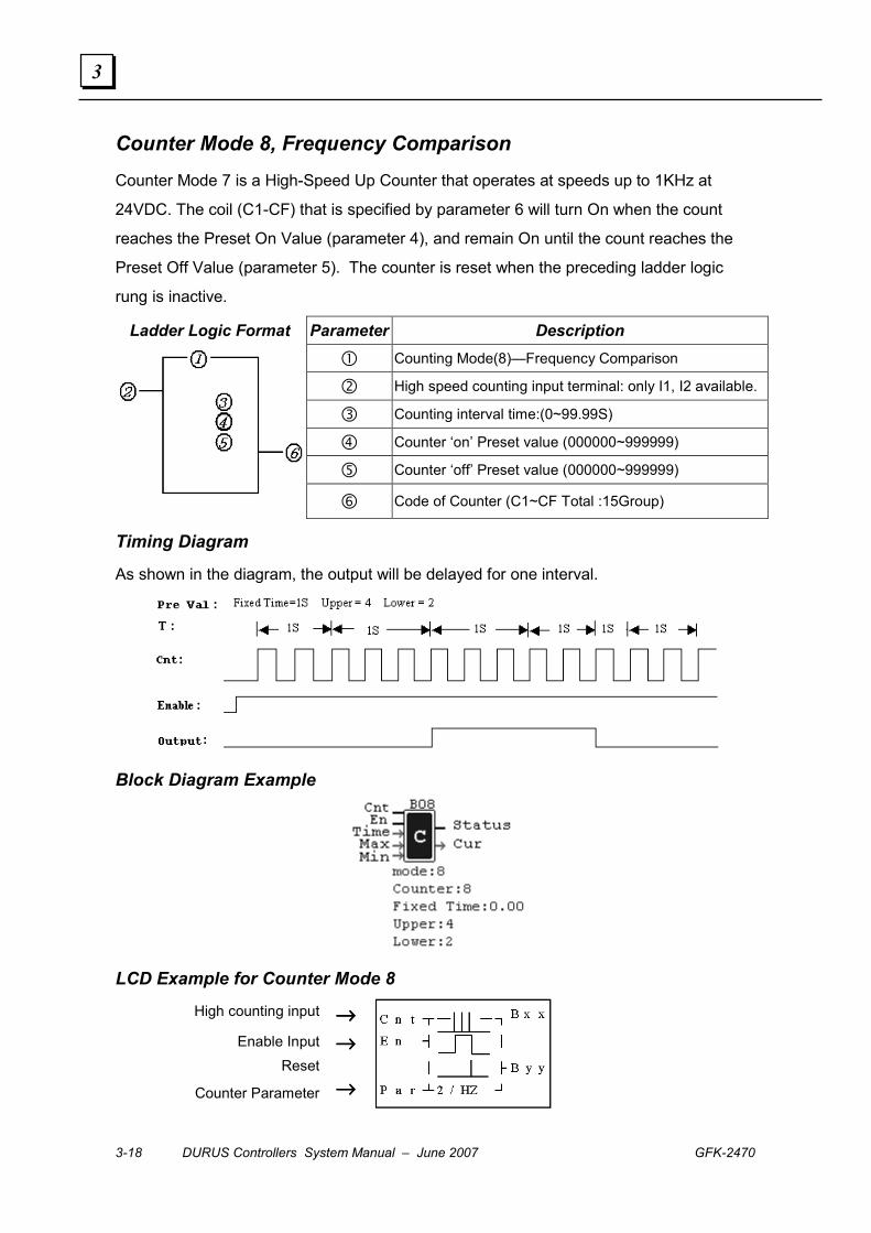
Counter Mode 8, Frequency Comparison Counter Mode 7 is a High-Speed Up Counter that operates at speeds up to 1KHz at
24VDC. The coil (C1-CF) that is specified by parameter 6 will turn On when the count
reaches the Preset On Value (parameter 4), and remain On until the count reaches the
Preset Off Value (parameter 5). The counter is reset when the preceding ladder logic
rung is inactive.
Parameter Description
� Counting Mode(8)—Frequency Comparison
� High speed counting input terminal: only I1, I2 available.
� Counting interval time:(0~99.99S)
� Counter ‘on’ Preset value (000000~999999)
� Counter ‘off’ Preset value (000000~999999)
Ladder Logic Format
� Code of Counter (C1~CF Total :15Group)
Timing Diagram
As shown in the diagram, the output will be delayed for one interval.
Block Diagram Example
LCD Example for Counter Mode 8
High counting input →→→→
Enable Input →→→→ Reset
Counter Parameter →→→→

GFK-2470 Chapter 3 Function Blocks 3-19
3
Timers
The controller provides 15 individual timers, each of which can count in any of seven
different modes. Six general counters types are available for all controller types. An
additional timer can be used as a pulse timer.
Parameter Description
� Timer Mode (1-7)
� Timer Units 1: 0.00~99.99s 2: 0.0~999.9s 3: 0~9999s 4: 0~9999m
� Use I1~gF to reset the timer value.
ON = timer value is reset to Zero and � OFF
OFF = timer continues timing
� Timer Current Value
� Timer Preset Value
Ladder Logic Parameters
� Code of timer (T1~TF total: 15Group)
Note: The setting value of a timer can be a constant, or the present value of the timer,
counter or analog input of A1~A4.
For I1~gF, input terminal:I1~IC (I1~I12), output terminal: Q1~Q8,expansion input
terminal:X1~XC(X1~X12),expansion output terminal:Y1~YF(Y1~Y12),Counter
:C1~CF(C1~C15),Timer :T1~TF(T1~T15) , RTC Comparator:R1~RF(R1~R15), analog
Comparator: G1~GF(G1~G15), Auxiliary terminal:M1~MF�M1~M15�.
The uppercase (I1) is Contact ‘a’ while the lowercase (i1) is Contact ‘b’.
3-20 DURUS Controllers System Manual – June 2007 GFK-2470
3
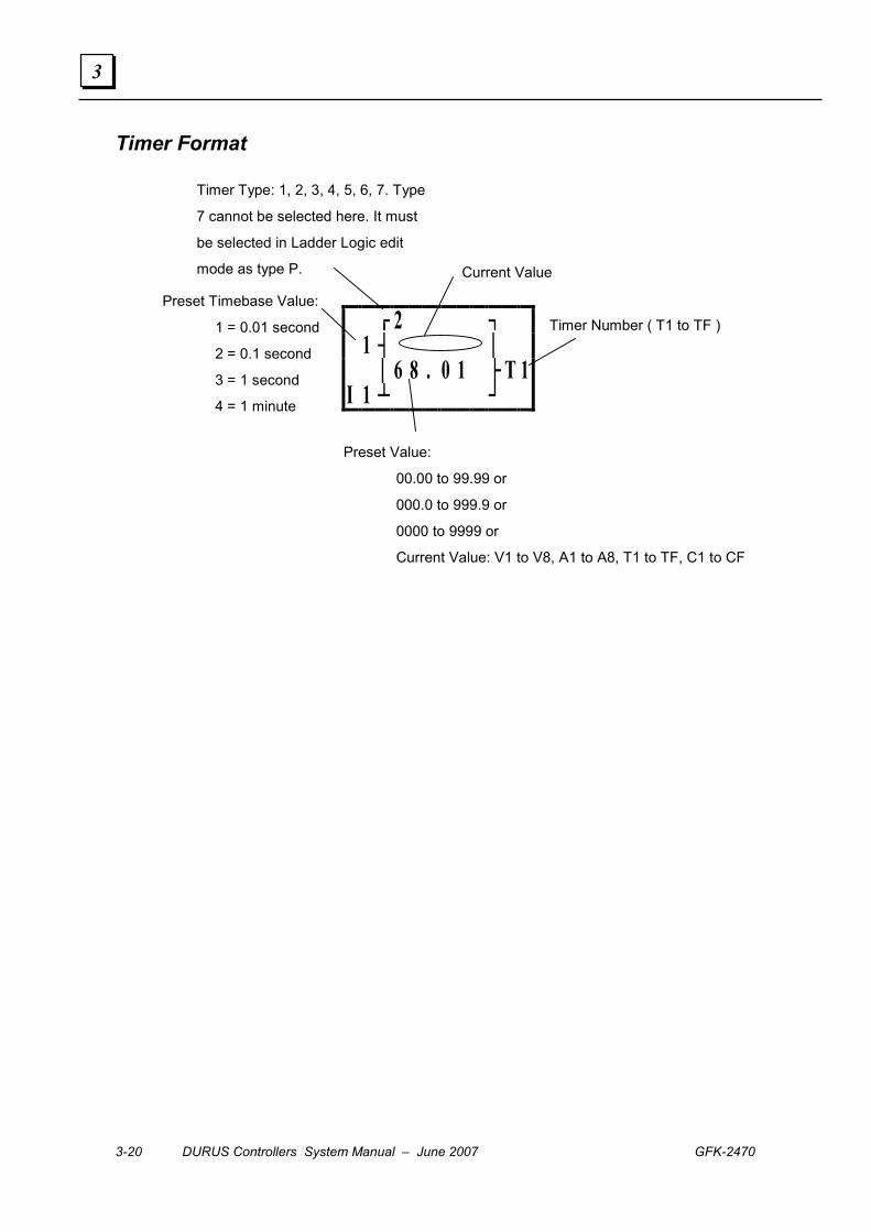
Timer Format
┌┘
2 ┐ 1 ┤ │ │ 6 8 . 0 1 ├ T 1I 1 ┴ ┘
Timer Number ( T1 to TF )
Preset Value:
00.00 to 99.99 or
000.0 to 999.9 or
0000 to 9999 or
Current Value: V1 to V8, A1 to A8, T1 to TF, C1 to CF
Current Value
Timer Type: 1, 2, 3, 4, 5, 6, 7. Type
7 cannot be selected here. It must
be selected in Ladder Logic edit
mode as type P.
Preset Timebase Value:
1 = 0.01 second
2 = 0.1 second
3 = 1 second
4 = 1 minute

GFK-2470 Chapter 3 Function Blocks 3-21
3
Timer Mode 1, On-Delay Mode Timer In Mode 1, the Timer will increment up to the Preset Value then stop. The Current Value of
the timer is non-retentive; it is reset to zero if power is lost. The Timer Status Bit T1 is On
when the Current Value is equal to the Preset Value.
Timing Diagrams
1. The time 't' is the preset value. When the present value reaches the preset value, it
will stop. And the output will be ON till the enable changed to OFF.
2. When the Enable is ON, the present value increases , or the preset value will be
cleared to 0 as the enable is OFF.
Block Diagram Example
LCD Example for Timer Mode 1
Enable Input →→→→
Timing Parameter →→→→

3-22 DURUS Controllers System Manual – June 2007 GFK-2470
3
Timer Mode 2, On Delay with Reset Input Timer Mode 2 is an On-Delay Timer. In Mode 2, the Timer will increment up to the Preset
Value then stop timing. The Current Value of the timer is non-retentive; it is reset to zero if
power is lost or if the Reset input is set to 1. The Timer Status Bit T1 is On when the
Current Value is equal to the Preset Value.
Reaction times of the relay that are less than the minimum units are ignored.
Timing Diagrams
The time 't' is the Current Value. In the first diagram, t=t1+t2.
The Current Value increases until it is equal to the Preset Value and stops. The output is
On until the Reset input is On.
Block Diagram Example
LCD Example for Timer Mode 2
Enable Input →→→→
Reset →→→→
Timing Parameter →→→→
GFK-2470 Chapter 3 Function Blocks 3-23
3
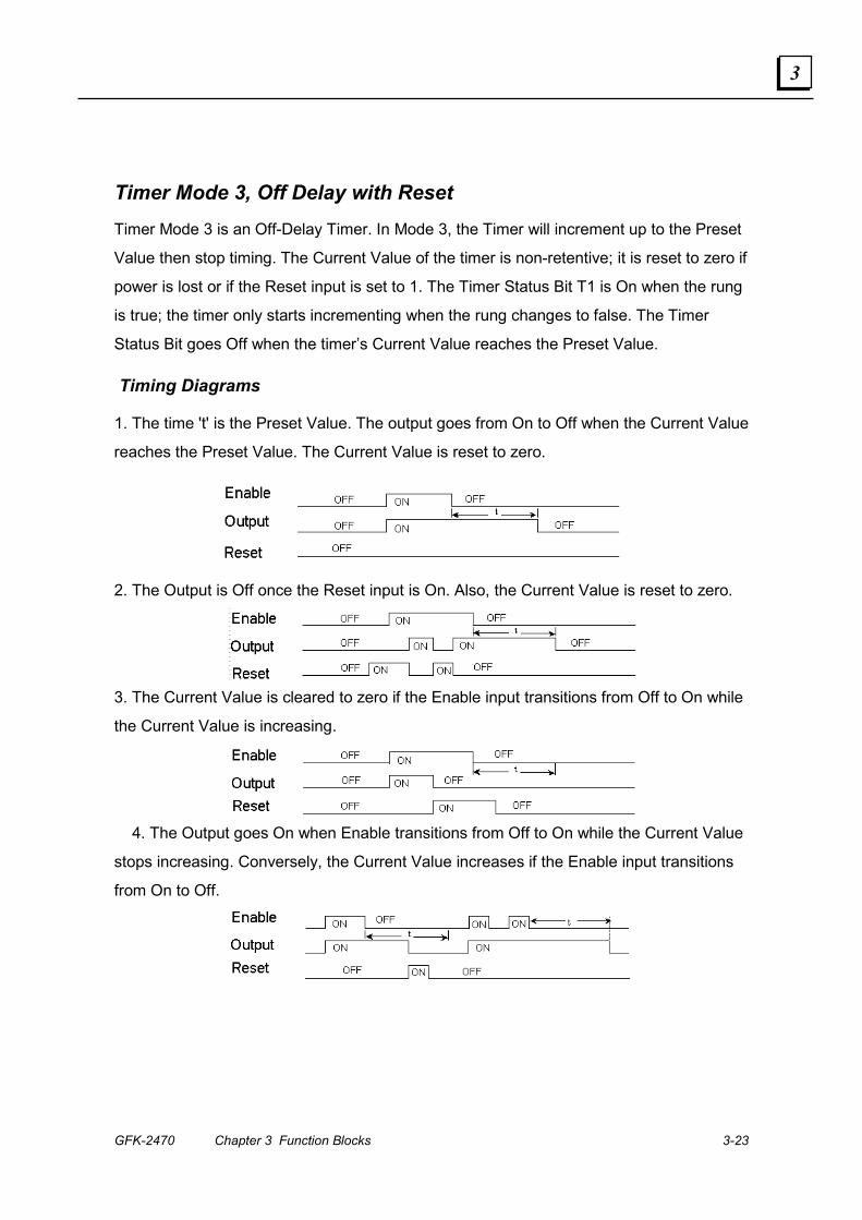
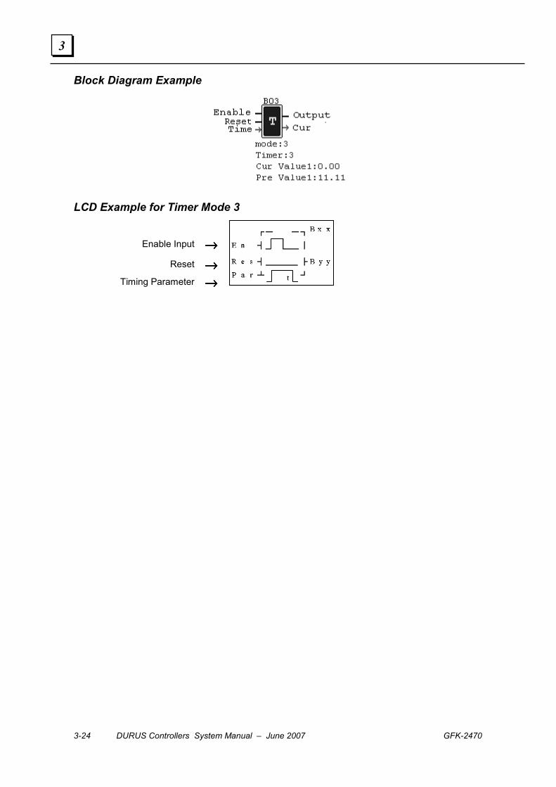
Timer Mode 3, Off Delay with Reset Timer Mode 3 is an Off-Delay Timer. In Mode 3, the Timer will increment up to the Preset
Value then stop timing. The Current Value of the timer is non-retentive; it is reset to zero if
power is lost or if the Reset input is set to 1. The Timer Status Bit T1 is On when the rung
is true; the timer only starts incrementing when the rung changes to false. The Timer
Status Bit goes Off when the timer’s Current Value reaches the Preset Value.
Timing Diagrams
1. The time 't' is the Preset Value. The output goes from On to Off when the Current Value
reaches the Preset Value. The Current Value is reset to zero.
2. The Output is Off once the Reset input is On. Also, the Current Value is reset to zero.
3. The Current Value is cleared to zero if the Enable input transitions from Off to On while
the Current Value is increasing.
4. The Output goes On when Enable transitions from Off to On while the Current Value
stops increasing. Conversely, the Current Value increases if the Enable input transitions
from On to Off.
3-24 DURUS Controllers System Manual – June 2007 GFK-2470
3
Block Diagram Example
LCD Example for Timer Mode 3
Enable Input →→→→
Reset →→→→
Timing Parameter →→→→

GFK-2470 Chapter 3 Function Blocks 3-25
3
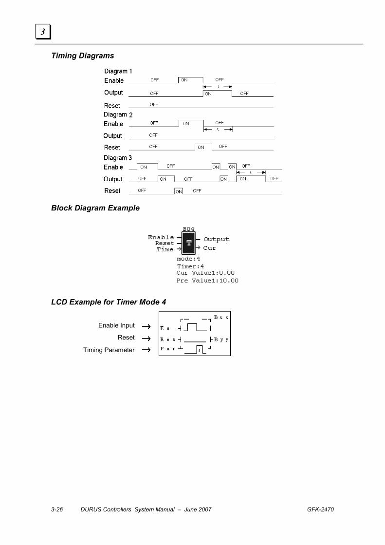
Timer Mode 4, Off Delay with Reset Timer Mode 4 is an Off-Delay Timer with a Reset input parameter. In Mode 4, the Timer
increments up to the Preset Value, then stops. The Current Value of the timer is non-
retentive; it is reset to zero if power is lost or if the Reset input is set to 1. The Timer
Status Bit T1 goes On and the Current Value starts incrementing when the rung
transitions from true to false. When the Current Value reaches the Preset Value, the Timer
Status Bit goes Off and the Preset Value is reset to zero.
If the Reset input goes On, the Present Value resets to zero and the timer output goes Off.
If the Enable input transitions from Off to On while the timer is incrementing, the Current
Value is cleared to zero.
When the Enable input transitions from Off to On, the output is Off and the Current Value
is held. When the Enable input goes from Off to On, the output goes On and the Current
Value starts incrementing.
3-26 DURUS Controllers System Manual – June 2007 GFK-2470
3
Timing Diagrams
Block Diagram Example
LCD Example for Timer Mode 4
Enable Input →→→→
Reset →→→→
Timing Parameter →→→→
GFK-2470 Chapter 3 Function Blocks 3-27
3
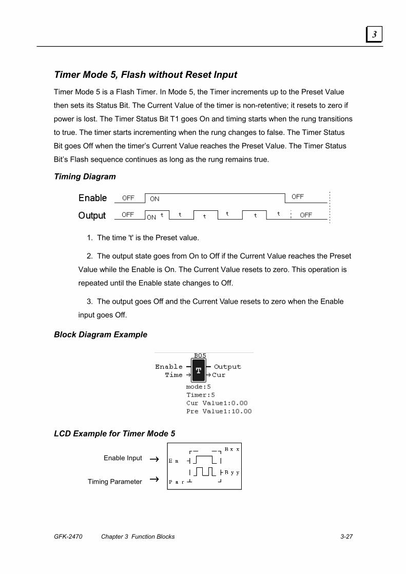
Timer Mode 5, Flash without Reset Input Timer Mode 5 is a Flash Timer. In Mode 5, the Timer increments up to the Preset Value
then sets its Status Bit. The Current Value of the timer is non-retentive; it resets to zero if
power is lost. The Timer Status Bit T1 goes On and timing starts when the rung transitions
to true. The timer starts incrementing when the rung changes to false. The Timer Status
Bit goes Off when the timer’s Current Value reaches the Preset Value. The Timer Status
Bit’s Flash sequence continues as long as the rung remains true.
Timing Diagram
1. The time 't' is the Preset value.
2. The output state goes from On to Off if the Current Value reaches the Preset
Value while the Enable is On. The Current Value resets to zero. This operation is
repeated until the Enable state changes to Off.
3. The output goes Off and the Current Value resets to zero when the Enable
input goes Off.
Block Diagram Example
LCD Example for Timer Mode 5
Enable Input →→→→
Timing Parameter →→→→
3-28 DURUS Controllers System Manual – June 2007 GFK-2470
3
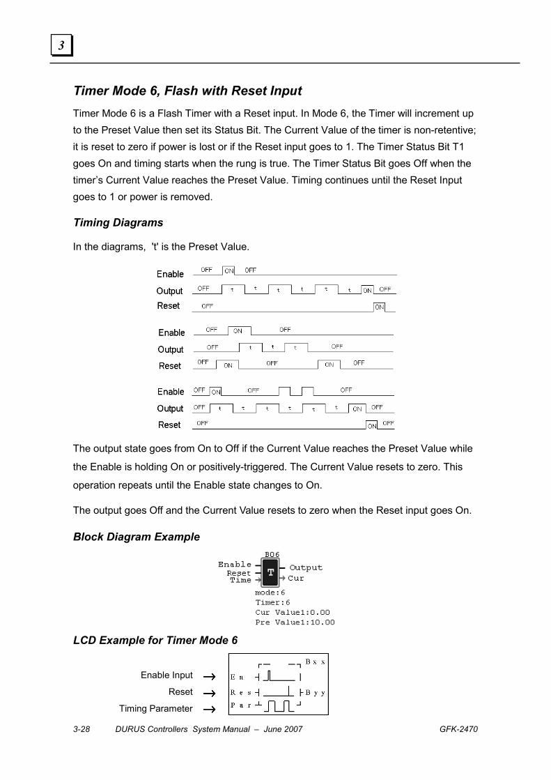
Timer Mode 6, Flash with Reset Input Timer Mode 6 is a Flash Timer with a Reset input. In Mode 6, the Timer will increment up to the Preset Value then set its Status Bit. The Current Value of the timer is non-retentive; it is reset to zero if power is lost or if the Reset input goes to 1. The Timer Status Bit T1 goes On and timing starts when the rung is true. The Timer Status Bit goes Off when the timer’s Current Value reaches the Preset Value. Timing continues until the Reset Input goes to 1 or power is removed.
Timing Diagrams
In the diagrams, 't' is the Preset Value.
The output state goes from On to Off if the Current Value reaches the Preset Value while
the Enable is holding On or positively-triggered. The Current Value resets to zero. This
operation repeats until the Enable state changes to On.
The output goes Off and the Current Value resets to zero when the Reset input goes On.
Block Diagram Example
LCD Example for Timer Mode 6
Enable Input →→→→
Reset →→→→ Timing Parameter →→→→
GFK-2470 Chapter 3 Function Blocks 3-29
3
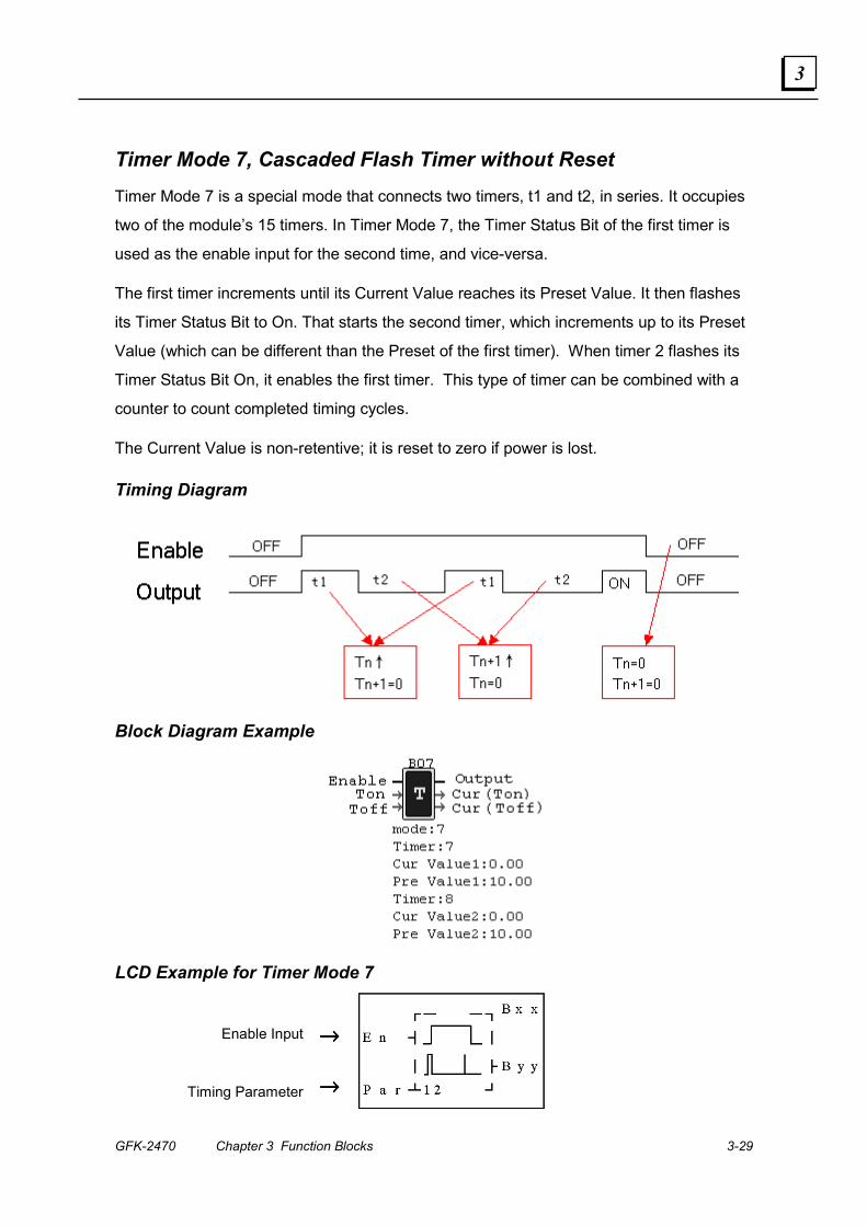
Timer Mode 7, Cascaded Flash Timer without Reset Timer Mode 7 is a special mode that connects two timers, t1 and t2, in series. It occupies
two of the module’s 15 timers. In Timer Mode 7, the Timer Status Bit of the first timer is
used as the enable input for the second time, and vice-versa.
The first timer increments until its Current Value reaches its Preset Value. It then flashes
its Timer Status Bit to On. That starts the second timer, which increments up to its Preset
Value (which can be different than the Preset of the first timer). When timer 2 flashes its
Timer Status Bit On, it enables the first timer. This type of timer can be combined with a
counter to count completed timing cycles.
The Current Value is non-retentive; it is reset to zero if power is lost.
Timing Diagram
Block Diagram Example
LCD Example for Timer Mode 7
Enable Input →→→→
Timing Parameter →→→→
3-30 DURUS Controllers System Manual – June 2007 GFK-2470
3
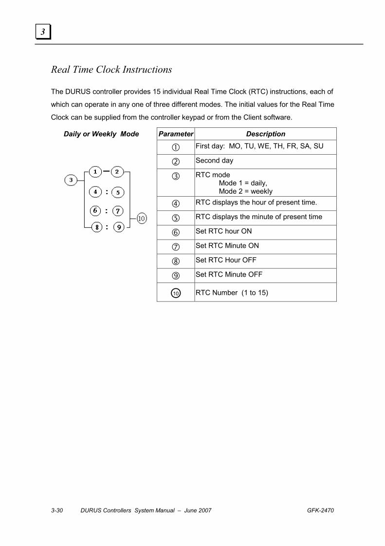
Real Time Clock Instructions
The DURUS controller provides 15 individual Real Time Clock (RTC) instructions, each of
which can operate in any one of three different modes. The initial values for the Real Time
Clock can be supplied from the controller keypad or from the Client software.
Parameter Description
� First day: MO, TU, WE, TH, FR, SA, SU
� Second day
� RTC mode Mode 1 = daily, Mode 2 = weekly
� RTC displays the hour of present time.
� RTC displays the minute of present time
� Set RTC hour ON
� Set RTC Minute ON
� Set RTC Hour OFF
Set RTC Minute OFF
Daily or Weekly Mode
○10 RTC Number (1 to 15)
GFK-2470 Chapter 3 Function Blocks 3-31
3
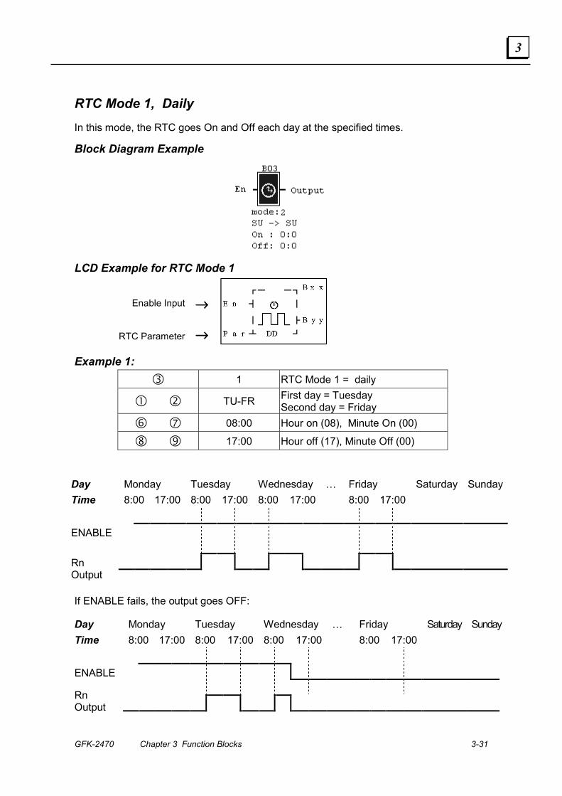
RTC Mode 1, Daily In this mode, the RTC goes On and Off each day at the specified times.
Block Diagram Example
LCD Example for RTC Mode 1
Enable Input →→→→
RTC Parameter →→→→
Example 1: � 1 RTC Mode 1 = daily
� � TU-FR First day = Tuesday Second day = Friday
� � 08:00 Hour on (08), Minute On (00)
� � 17:00 Hour off (17), Minute Off (00)
Day Monday Tuesday Wednesday … Friday Saturday Sunday Time 8:00 17:00 8:00 17:00 8:00 17:00 8:00 17:00 ENABLE
Rn Output
If ENABLE fails, the output goes OFF:
Day Monday Tuesday Wednesday … Friday Saturday Sunday Time 8:00 17:00 8:00 17:00 8:00 17:00 8:00 17:00 ENABLE
Rn Output
3-32 DURUS Controllers System Manual – June 2007 GFK-2470
3
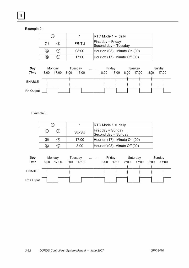
Example 2:
� 1 RTC Mode 1 = daily
� � FR-TU First day = Friday Second day = Tuesday
� � 08:00 Hour on (08), Minute On (00)
� � 17:00 Hour off (17), Minute Off (00)
Day Monday Tuesday … … Friday Saturday Sunday Time 8:00 17:00 8:00 17:00 8:00 17:00 8:00 17:00 8:00 17:00
ENABLE
Rn Output
Example 3:
� 1 RTC Mode 1 = daily
� � SU-SU First day = Sunday Second day = Sunday
� � 17:00 Hour on (17), Minute On (00)
� � 8:00 Hour off (08), Minute Off (00)
Day Monday Tuesday … … Friday Saturday Sunday Time 8:00 17:00 8:00 17:00 8:00 17:00 8:00 17:00 8:00 17:00
ENABLE
Rn Output
GFK-2470 Chapter 3 Function Blocks 3-33
3
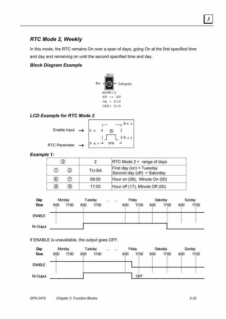
RTC Mode 2, Weekly
In this mode, the RTC remains On over a span of days, going On at the first specified time
and day and remaining on until the second specified time and day.
Block Diagram Example
LCD Example for RTC Mode 2
Enable Input →→→→
RTC Parameter →→→→
Example 1: � 2 RTC Mode 2 = range of days
� � TU-SA First day (on) = Tuesday Second day (off) = Saturday
� � 08:00 Hour on (08), Minute On (00)
� � 17:00 Hour off (17), Minute Off (00)
Day Monday Tuesday … … Friday Saturday Sunday Time 8:00 17:00 8:00 17:00 8:00 17:00 8:00 17:00 8:00 17:00
ENABLE
Rn Output
If ENABLE is unavailable, the output goes OFF.
Day Monday Tuesday … … Friday Saturday Sunday Time 8:00 17:00 8:00 17:00 8:00 17:00 8:00 17:00 8:00 17:00
ENABLE
Rn Output OFF

3-34 DURUS Controllers System Manual – June 2007 GFK-2470
3
Example 2: � 2 RTC Mode 2 = Range of Days
� � TU-SA First day (on) = Tuesday Second day (off) = Saturday
� � 17:00 Hour on (17), Minute On (00)
� � 08:00 Hour off (08), Minute Off (00)
Day Monday Tuesday … … Friday Saturday Sunday Time 8:00 17:00 8:00 17:00 8:00 17:00 8:00 17:00 8:00 17:00
ENABLE
Rn Output
Example 3: � 2 RTC Mode 2 = Range of Days
� � SA-TU First day (on) = Saturday Second day (off) = Tuesday
� � 08:00 Hour on (08), Minute On (00)
� � 17:00 Hour off (17), Minute Off (00)
Day Monday Tuesday … … Friday Saturday Sunday Time 8:00 17:00 8:00 17:00 8:00 17:00 8:00 17:00 8:00 17:00
ENABLE
Rn Output
Example 4:
In this example, because the start time comes before the end time, the RTC goes On and
Off the same Saturday.
� 2 RTC Mode 2 = Range of Days
� � SA-SA First day (on) = Saturday Second day (off) = Saturday
� � 08:00 Hour on (08), Minute On (00)
� � 17:00 Hour off (17), Minute Off (00)
Day Monday Tuesday … … Friday Saturday Sunday Time 8:00 17:00 8:00 17:00 8:00 17:00 8:00 17:00 8:00 17:00
ENABLE
Rn Output
GFK-2470 Chapter 3 Function Blocks 3-35
3
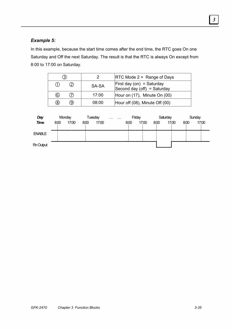
Example 5:
In this example, because the start time comes after the end time, the RTC goes On one
Saturday and Off the next Saturday. The result is that the RTC is always On except from
8:00 to 17:00 on Saturday.
� 2 RTC Mode 2 = Range of Days
� � SA-SA First day (on) = Saturday Second day (off) = Saturday
� � 17:00 Hour on (17), Minute On (00)
� � 08:00 Hour off (08), Minute Off (00)
Day Monday Tuesday … … Friday Saturday Sunday Time 8:00 17:00 8:00 17:00 8:00 17:00 8:00 17:00 8:00 17:00
ENABLE
Rn Output

3-36 DURUS Controllers System Manual – June 2007 GFK-2470
3
RTC Mode 3: Year, Month, Day Operation Year-Month-Day Mode
Block Diagram Example
LCD Example for RTC Mode 3
Enable Input →→→→
RTC Parameter →→→→
Parameter Description
� RTC mode 3 = Year-Month-Day
� Set RTC Year ON
� Set RTC Year OFF
� Display RTC Present time: Year-Month-Day
� Set RTC month ON
� Set RTC Day ON
� Set RTC month OFF
� Set RTC Day OFF
RTC Number (1 to 15)
GFK-2470 Chapter 3 Function Blocks 3-37
3
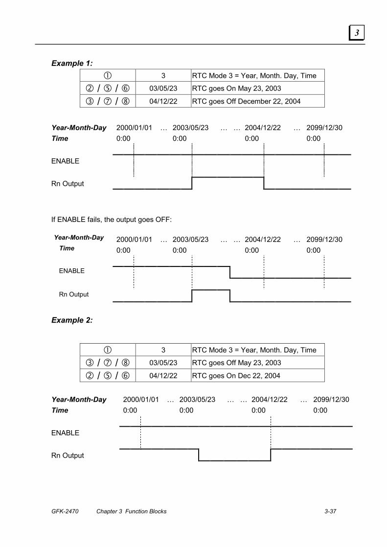
Example 1: � 3 RTC Mode 3 = Year, Month. Day, Time
� / � / � 03/05/23 RTC goes On May 23, 2003
� / � / � 04/12/22 RTC goes Off December 22, 2004
Year-Month-Day 2000/01/01 … 2003/05/23 … … 2004/12/22 … 2099/12/30 Time 0:00 0:00 0:00 0:00 ENABLE Rn Output
If ENABLE fails, the output goes OFF:
Year-Month-Day 2000/01/01 … 2003/05/23 … … 2004/12/22 … 2099/12/30 Time 0:00 0:00 0:00 0:00
ENABLE
Rn Output
Example 2:
� 3 RTC Mode 3 = Year, Month. Day, Time
� / � / � 03/05/23 RTC goes Off May 23, 2003
� / � / � 04/12/22 RTC goes On Dec 22, 2004
Year-Month-Day 2000/01/01 … 2003/05/23 … … 2004/12/22 … 2099/12/30Time 0:00 0:00 0:00 0:00 ENABLE Rn Output
3-38 DURUS Controllers System Manual – June 2007 GFK-2470
3
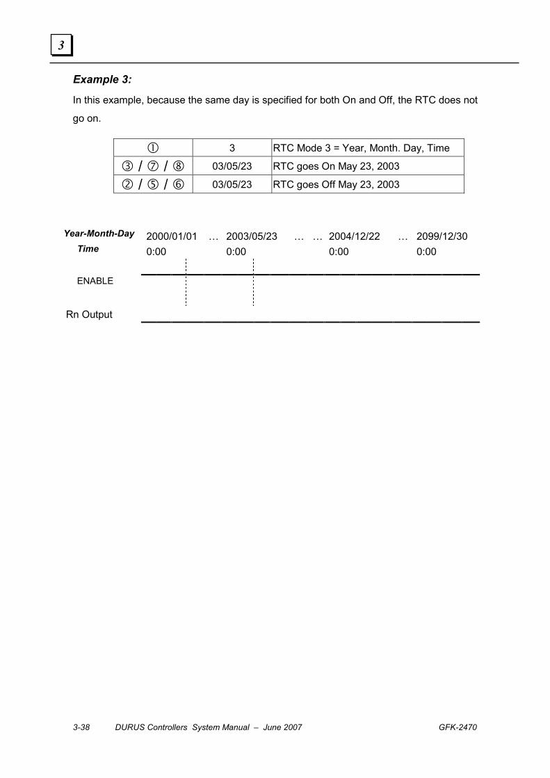
Example 3:
In this example, because the same day is specified for both On and Off, the RTC does not
go on.
� 3 RTC Mode 3 = Year, Month. Day, Time
� / � / � 03/05/23 RTC goes On May 23, 2003
� / � / � 03/05/23 RTC goes Off May 23, 2003
Year-Month-Day 2000/01/01 … 2003/05/23 … … 2004/12/22 … 2099/12/30
Time 0:00 0:00 0:00 0:00 ENABLE
Rn Output
GFK-2470 Chapter 3 Function Blocks 3-39
3
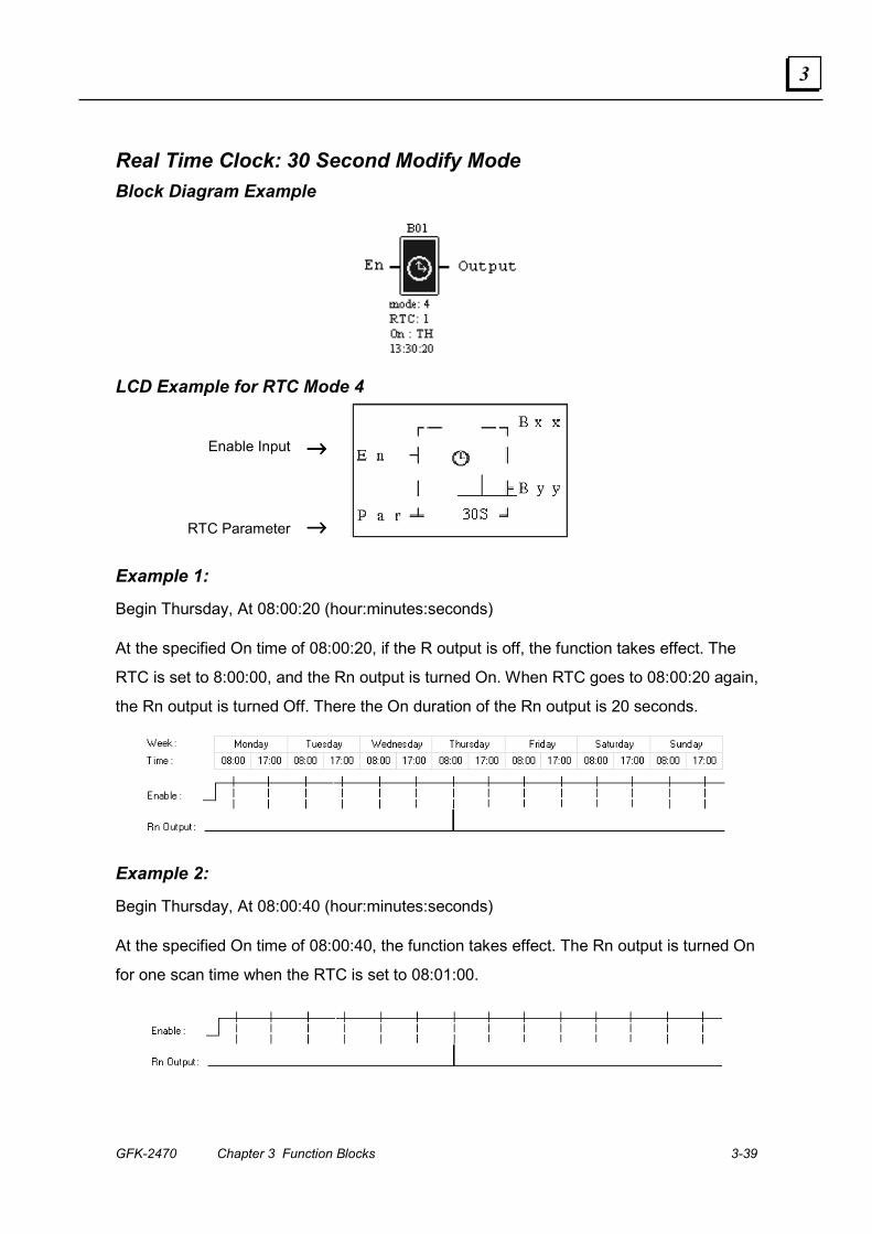
Real Time Clock: 30 Second Modify Mode Block Diagram Example
LCD Example for RTC Mode 4
Enable Input →→→→
RTC Parameter →→→→
Example 1:
Begin Thursday, At 08:00:20 (hour:minutes:seconds)
At the specified On time of 08:00:20, if the R output is off, the function takes effect. The
RTC is set to 8:00:00, and the Rn output is turned On. When RTC goes to 08:00:20 again,
the Rn output is turned Off. There the On duration of the Rn output is 20 seconds.
Example 2:
Begin Thursday, At 08:00:40 (hour:minutes:seconds)
At the specified On time of 08:00:40, the function takes effect. The Rn output is turned On
for one scan time when the RTC is set to 08:01:00.

3-40 DURUS Controllers System Manual – June 2007 GFK-2470
3
Compare Functions
The DURUS controller provide 15 individual Compare instructions. They can be used to
compare analog values, timers, counters and RTC values to each other, or to a specified
parameter value.
The ON or Off state of the output terminal (G1 through GF) depends on the comparison
of inputs of Ax and Ay. There are five Compare modes:
▪ Compare mode 1: If AY - ⑥ ≤ AX ≤ AY + ⑥, turn output terminal ⑦ On
▪ Compare mode 2: If AX ≤ AY, turn output terminal ⑦ On
▪ Compare mode 3: If AX ≥ AY, turn output terminal ⑦ On
▪ Compare mode 4: If AX ≤ ⑥, turn output terminal ⑦ On
▪ Compare mode 5: If AX ≥ ⑥, turn output terminal ⑦ On
Parameter Description
� Compare Mode (1~5)
� AX analog input (A1~A4), the present value of a timer or counter, or a constant.
� AY analog input (A1~A4), the present value of a timer or counter, or a constant.
� AX analog input value(0.00~9.99)
� AY analog input value (0.00~9.99)
� Set reference comparative value: could be constant, or the present value of the timer, counter or analog input.
� Output terminal (G1~GF)
GFK-2470 Chapter 3 Function Blocks 3-41
3
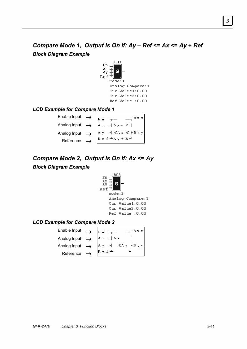
Compare Mode 1, Output is On if: Ay – Ref <= Ax <= Ay + Ref Block Diagram Example
LCD Example for Compare Mode 1
Enable Input →→→→
Analog Input →→→→
Analog Input →→→→ Reference →→→→
Compare Mode 2, Output is On if: Ax <= Ay Block Diagram Example
LCD Example for Compare Mode 2
Enable Input →→→→ Analog Input →→→→ Analog Input →→→→
Reference →→→→

3-42 DURUS Controllers System Manual – June 2007 GFK-2470
3
Compare Mode 3, Output is On if: Ax => Ay Block Diagram Example
LCD Example for Compare Mode 3
Enable Input →→→→ Analog Input →→→→ Analog Input →→→→
Reference →→→→
Compare Mode 4, Output is On if: Ref >= Ax Block Diagram Example
LCD Example for Compare Mode 4 Enable Input →→→→
Analog Input →→→→
Reference →→→→
GFK-2470 Chapter 3 Function Blocks 3-43
3
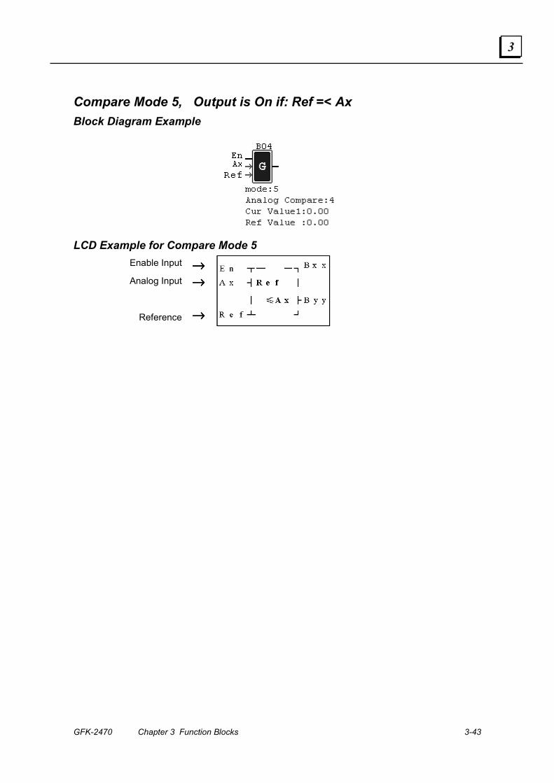
Compare Mode 5, Output is On if: Ref =< Ax Block Diagram Example
LCD Example for Compare Mode 5 Enable Input →→→→ Analog Input →→→→
Reference →→→→
3-44 DURUS Controllers System Manual – June 2007 GFK-2470
3
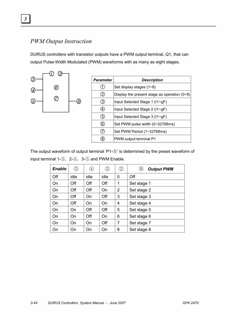
PWM Output Instruction
DURUS controllers with transistor outputs have a PWM output terminal, Q1, that can
output Pulse-Width Modulated (PWM) waveforms with as many as eight stages.
The output waveform of output terminal ‘P1-⑧’ is determined by the preset waveform of
input terminal 1-③,2-④,3-⑤ and PWM Enable.
Enable ⑤ ④ ③ ② ⑧ ⑧⑧ ⑧⑧ Output PWM
Off idle idle idle 0 Off On Off Off Off 1 Set stage 1 On Off Off On 2 Set stage 2 On Off On Off 3 Set stage 3 On Off On On 4 Set stage 4 On On Off Off 5 Set stage 5 On On Off On 6 Set stage 6 On On On Off 7 Set stage 7 On On On On 8 Set stage 8
Parameter Description
� Set display stages (1~8)
� Display the present stage as operation (0~8)
� Input Selected Stage 1 (I1~gF)
� Input Selected Stage 2 (I1~gF)
� Input Selected Stage 3 (I1~gF)
� Set PWM pulse width (0~32768ms)
� Set PWM Period (1~32768ms)
� PWM output terminal P1
GFK-2470 Chapter 3 Function Blocks 3-45
3
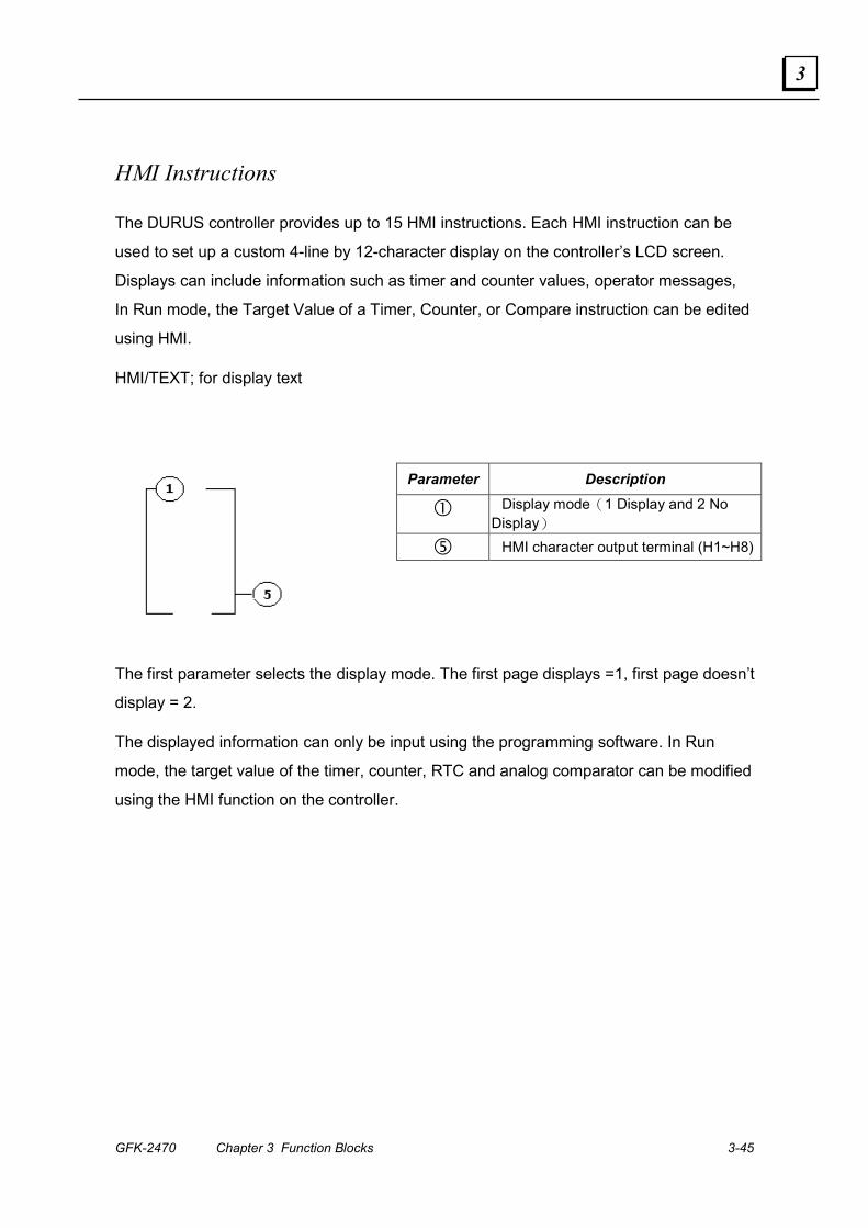
HMI Instructions
The DURUS controller provides up to 15 HMI instructions. Each HMI instruction can be
used to set up a custom 4-line by 12-character display on the controller’s LCD screen.
Displays can include information such as timer and counter values, operator messages,
In Run mode, the Target Value of a Timer, Counter, or Compare instruction can be edited
using HMI.
HMI/TEXT; for display text
The first parameter selects the display mode. The first page displays =1, first page doesn’t
display = 2.
The displayed information can only be input using the programming software. In Run
mode, the target value of the timer, counter, RTC and analog comparator can be modified
using the HMI function on the controller.
Parameter Description
� Display mode(1 Display and 2 No Display)
� HMI character output terminal (H1~H8)
3-46 DURUS Controllers System Manual – June 2007 GFK-2470
3
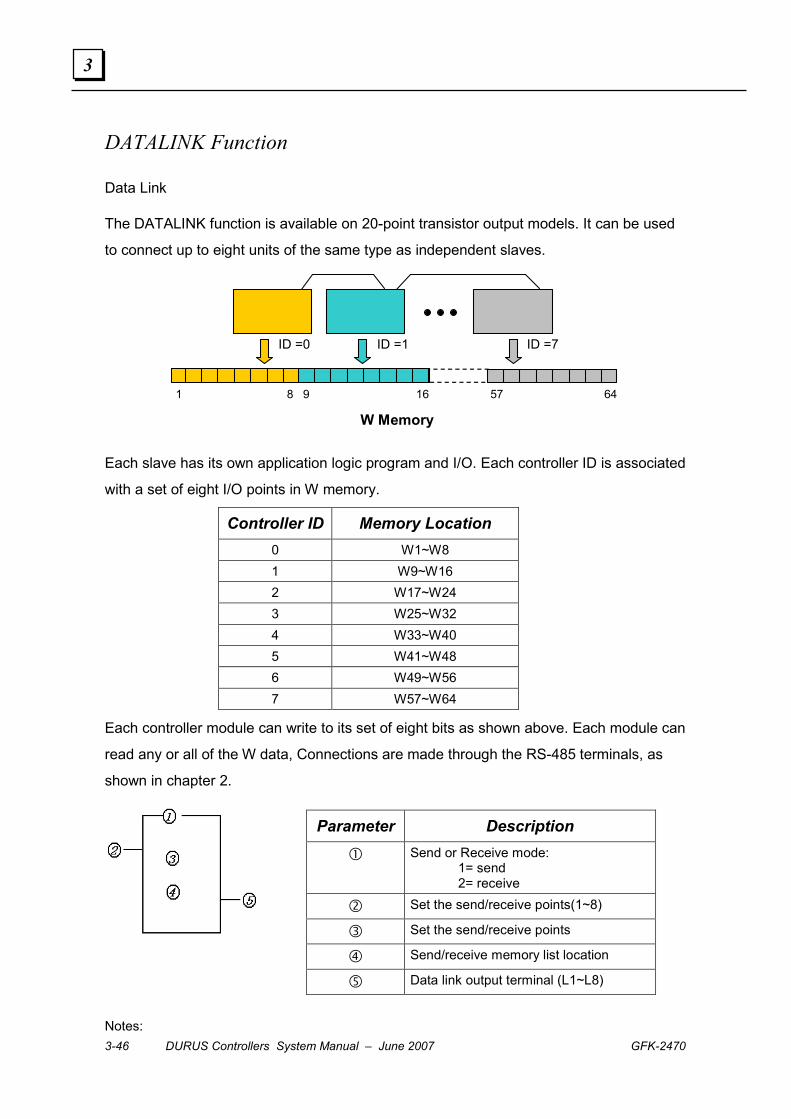
DATALINK Function
Data Link
The DATALINK function is available on 20-point transistor output models. It can be used
to connect up to eight units of the same type as independent slaves.
W Memory
1 8 9 16 57 64
ID =0 ID =1 ID =7
Each slave has its own application logic program and I/O. Each controller ID is associated
with a set of eight I/O points in W memory.
Controller ID Memory Location 0 W1~W8 1 W9~W16 2 W17~W24 3 W25~W32 4 W33~W40 5 W41~W48 6 W49~W56 7 W57~W64
Each controller module can write to its set of eight bits as shown above. Each module can
read any or all of the W data, Connections are made through the RS-485 terminals, as
shown in chapter 2.
Notes:
Parameter Description
� Send or Receive mode: 1= send 2= receive
� Set the send/receive points(1~8)
� Set the send/receive points
� Send/receive memory list location
� Data link output terminal (L1~L8)
GFK-2470 Chapter 3 Function Blocks 3-47
3
① Only one unit can be set up for Send mode. That unit will operate as the Master. The
other units on the link must be set up for Receive mode, and will operate as the Slaves.
② Selecting input points: I1~IC(I12), output points: Q1~Q8, expansion input points:
X1~XC (X12), expansion output points: Y1~YF( Y15), auxiliary points: M1~MF (M15).
③ In Receive mode, the memory range is determined by the controller ID which cannot
be changed.
I1———— (L1
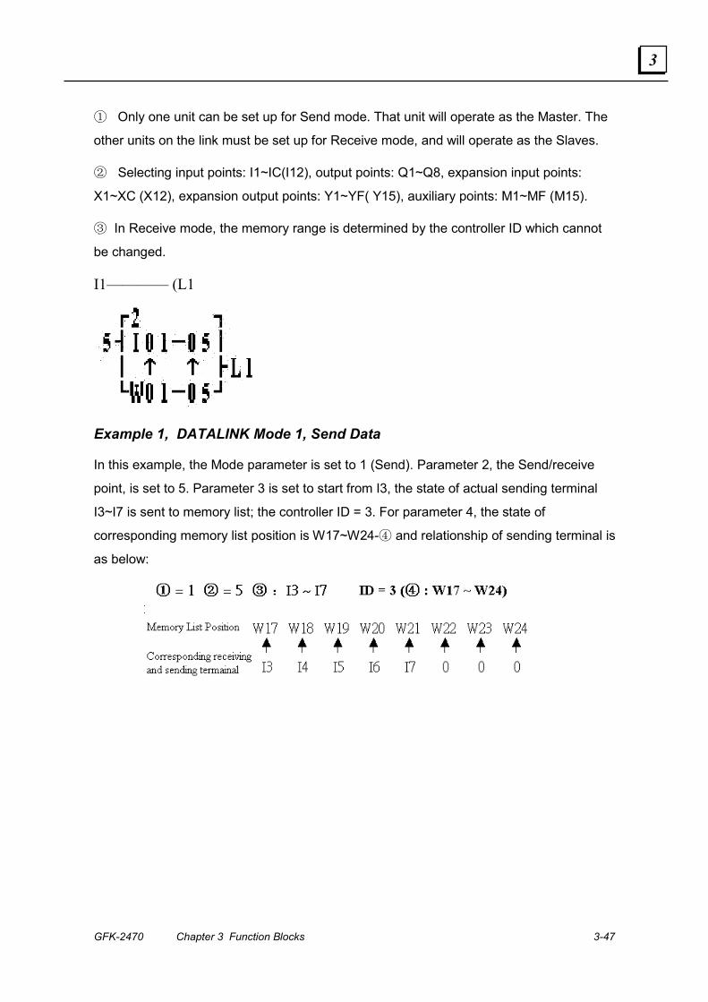
Example 1, DATALINK Mode 1, Send Data
In this example, the Mode parameter is set to 1 (Send). Parameter 2, the Send/receive
point, is set to 5. Parameter 3 is set to start from I3, the state of actual sending terminal
I3~I7 is sent to memory list; the controller ID = 3. For parameter 4, the state of
corresponding memory list position is W17~W24-④ and relationship of sending terminal is
as below:

3-48 DURUS Controllers System Manual – June 2007 GFK-2470
3
Example 2, DATALINK Mode 2, Receive Data
Set parameter 1 to 2 . Set parameter 2 to 5. Set parameter 3 to start from I3. Set
parameter 4 to start from W17. When enabling the Datalink, the state ‘ON/OFF’ of I3~I7 is
controlled by the state of parameter 4, memory list position W17~W21, which is
independent of the actual state of input terminal.

GFK-2470 4-1
Keypad Operations in Ladder Logic Mode
This chapter explains how navigate the controller LCD screens and make changes using
the built-in keypad, in Ladder Logic mode.
▪ Startup Screen
▪ Controller Main Menu in Ladder Mode
▪ Editing Ladder Logic
▪ Editing Function Blocks
▪ Run/Stop the Controller
▪ Clear the Current Program
▪ Write a Program
▪ Change the Controller Setup
▪ Set the Real-time Clock
▪ Enter Analog Gain and Offset
▪ Set or Change a Password
▪ Change the Display Language
▪ View Point States
▪ Display the Application’s HMI Screens
▪ Ladder Logic Editing on the Controller
▪ Function Block Editing on the Controller
Chapter
4

4-2 DURUS Controllers System Manual – June 2007 GFK-2470
4
Startup Screen
By default, the controller LCD screen shows:
Input On / Off States
= On =Off
Run / Stop Mode
Output On / Off States
Point Numbers
Real-Time Clock Day, Date: Month
Use the module keypad to navigate and edit the display:
From this screen, the keypad actions are:
ESC Return to Main Menu
SEL+↑ ↓ In Ladder Edit Mode, display the state of other relays as shown on the next page.
SEL If the HMI function is enabled, HMI screens that have been created using the programming software are displayed if the SEL button is pressed for 3 seconds.
GFK-2470 Chapter 4 Keypad Operations in Ladder Logic Mode 4-3
4
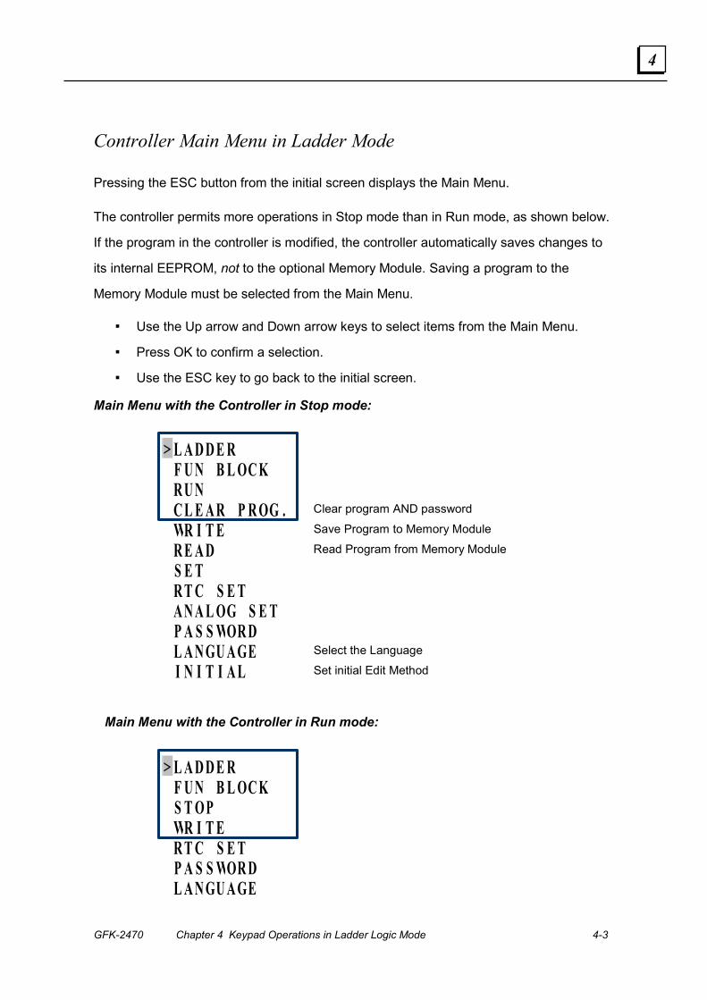
Controller Main Menu in Ladder Mode
Pressing the ESC button from the initial screen displays the Main Menu.
The controller permits more operations in Stop mode than in Run mode, as shown below.
If the program in the controller is modified, the controller automatically saves changes to
its internal EEPROM, not to the optional Memory Module. Saving a program to the
Memory Module must be selected from the Main Menu.
▪ Use the Up arrow and Down arrow keys to select items from the Main Menu.
▪ Press OK to confirm a selection.
▪ Use the ESC key to go back to the initial screen.
Main Menu with the Controller in Stop mode:
> L A D D E R
F U N B L OC K
R U N
C L E A R P R OG . Clear program AND password
WR I T E Save Program to Memory Module
R E A D Read Program from Memory Module
S E T
R T C S E T
A N A L OG S E T
P A S S WOR D
L A N GU A GE Select the Language
I N I T I A L Set initial Edit Method
Main Menu with the Controller in Run mode:
> L A D D E R
F U N B L OC K
S T OP
WR I T E
R T C S E T
P A S S WOR D
L A N GU A GE
4-4 DURUS Controllers System Manual – June 2007 GFK-2470
4
Edit Ladder Logic
Select Ladder and press OK. See Ladder Logic Editing on the Controller later in this
chapter for instructions.
Edit Function Blocks
Select FUNction BLOCK from the menu to edit Timers, Counters, Analog Compare
Functions, and other Function Blocks. See Function Block Editing on the Controller later in
this chapter for instructions.
Run / Stop the Controller
Select RUN or STOP from the menu to set the controller mode.
L A D D E RF U N . B L OC K
> R U NC L E A R P R OG .
Selecting RUN places the controller in Run mode. Selecting STOP places the controller in
Stop mode.
Clear the Current Program
In Stop mode, select Clear Program from the menu to clear the program and passwords.
This function can only be used in Stop mode.
L A D D E RF U N . B L OC KR U N
> C L E A R P R OG .

GFK-2470 Chapter 4 Keypad Operations in Ladder Logic Mode 4-5
4
Write a Program
Select Write from the menu (by scrolling down) to write the program from the controller to
the Memory Option Module.
F U N . B L OC KR U NC L E A R P R OG .
> WR I T E
Read a Program
In Stop mode, select Read from the menu (by scrolling down) to read the program from
the Memory Option Module to the controller.
R U NC L E A R P R OG .WR I T E
> R E A D

4-6 DURUS Controllers System Manual – June 2007 GFK-2470
4
Change the Controller Setup
In Stop mode, select Set from the menu (by scrolling down) to change the setup
parameters for the controller.
C L E A R P R OG .WR I T ER E A D
> S E T
Select the setup parameters:
I D S E T 0 0 RE MOT E I / O NB A C K L I GHT ✗
M KE E P
I / O N U MB E R : 0 I / O A L A R M: �
C K E E P ✗
Z S E T
Set ID Number (00 to 99)
Select Remote I/O: None, Master, Slave
Turn on the LCD screen backlight
Make M instruction status retentive
Number of Expansion modules (0 to 3)
Alarm if Expansion Number not matched
Save Counter Current Value during Run/Stop
Enable Z inputs
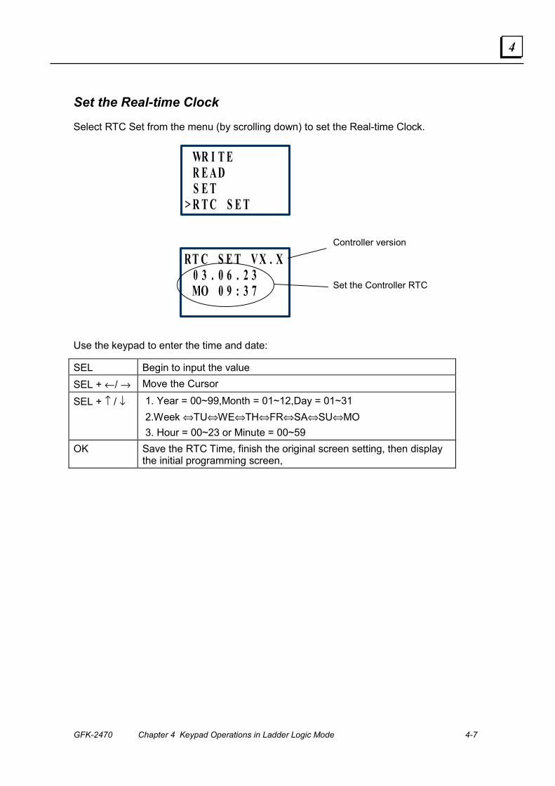
GFK-2470 Chapter 4 Keypad Operations in Ladder Logic Mode 4-7
4
Set the Real-time Clock
Select RTC Set from the menu (by scrolling down) to set the Real-time Clock.
WR I T E R E A D S E T
> R T C S E T
RT C S E T V X . X 0 3 . 0 6 . 2 3 MO 0 9 : 3 7
Controller version
Set the Controller RTC
Use the keypad to enter the time and date:
SEL Begin to input the value SEL + ←/ → Move the Cursor
SEL + ↑ / ↓ 1. Year = 00~99,Month = 01~12,Day = 01~31 2.Week ⇔TU⇔WE⇔TH⇔FR⇔SA⇔SU⇔MO 3. Hour = 00~23 or Minute = 00~59
OK Save the RTC Time, finish the original screen setting, then display the initial programming screen,
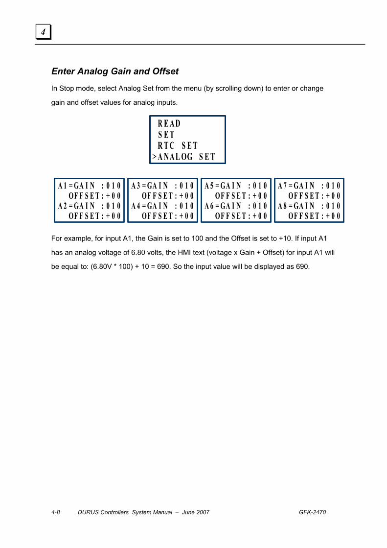
4-8 DURUS Controllers System Manual – June 2007 GFK-2470
4
Enter Analog Gain and Offset
In Stop mode, select Analog Set from the menu (by scrolling down) to enter or change
gain and offset values for analog inputs.
R E A D S E T R T C S E T
> A N A L OG S E T
A 1 = GA I N : 0 1 0 OF F S E T : + 0 0
A 2 = GA I N : 0 1 0 OF F S E T : + 0 0
A 3 = GA I N : 0 1 0 OF F S E T : + 0 0
A 4 = GA I N : 0 1 0 OF F S E T : + 0 0
A 5 = GA I N : 0 1 0OF F S E T : + 0 0
A 6 = GA I N : 0 1 0OF F S E T : + 0 0
A 7 = GA I N : 0 1 0 OF F S E T : + 0 0
A 8 = GA I N : 0 1 0 OF F S E T : + 0 0
For example, for input A1, the Gain is set to 100 and the Offset is set to +10. If input A1
has an analog voltage of 6.80 volts, the HMI text (voltage x Gain + Offset) for input A1 will
be equal to: (6.80V * 100) + 10 = 690. So the input value will be displayed as 690.
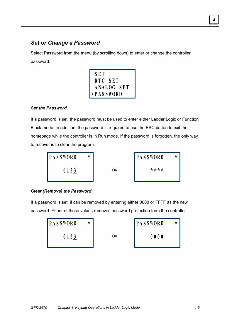
GFK-2470 Chapter 4 Keypad Operations in Ladder Logic Mode 4-9
4
Set or Change a Password
Select Password from the menu (by scrolling down) to enter or change the controller
password.
S E T R T C S E T A N A L OG S E T
> P A S S WOR D
Set the Password
If a password is set, the password must be used to enter either Ladder Logic or Function
Block mode. In addition, the password is required to use the ESC button to exit the
homepage while the controller is in Run mode. If the password is forgotten, the only way
to recover is to clear the program.
P A S S WOR D ✘
0 1 2 3
P A S S WOR D ✘
****
OK
Clear (Remove) the Password
If a password is set, if can be removed by entering either 0000 or FFFF as the new
password. Either of those values removes password protection from the controller.
P A S S WOR D ✘
0 1 2 3
P A S S WOR D ✘
0 0 0 0
OK

4-10 DURUS Controllers System Manual – June 2007 GFK-2470
4
Change the Display Language
Select Language from the menu (by scrolling down) to change the display language.
R T C S E T A N A L OG S E T P A S S WOR D
> L A N GU A GE
> E N GL I S H �
F R A N ç A I S E S P A ÑÑÑÑ OL I T A L I A N O D E U T S C H P OR T U GU E S 筒 体 中 文

GFK-2470 Chapter 4 Keypad Operations in Ladder Logic Mode 4-11
4
View Point States
From the initial screen, use the SELect and Arrow keys to display the point states.
SEL +
1 2 3 4 5 6 7 8 9 ABC
R U N WE 0 9 : 2 4A 1 = 6 . 8 3 VA 2 = 1 . 3 3 VA 3 = 4 . 8 7 VA 4 = 1 . 5 4 V
1 2 3 4 5 6 7 8 9 ABC
D E F G
1 2 3 4 5 6 7 8 9 ABC
D E F R
1 2 3 4 5 6 7 8 9 ABC
D E F C
1 2 3 4 5 6 7 8 9 ABC
D E F T
1 2 3 4 5 6 7 8 9 ABC
D E F M
1 2 3 4 5 6 7 8 9 ABC
0 3 . 1 0 : 0 4
1 2 3 4 5 6 7 8 9 ABC
R U N WE 0 9 : 2 4
Analog Input Values
G Table States: analog comparator
R Table States: RTC
C Table States: Counter
T Table States: Timer
M Table States: Auxiliary coil
RTC in Year, Month, Date Format
SEL +
SEL +
SEL +
SEL +
SEL +
SEL +
SEL +
SEL +
SEL +
SEL +
SEL +
SEL +
SEL +
SEL +
SEL +
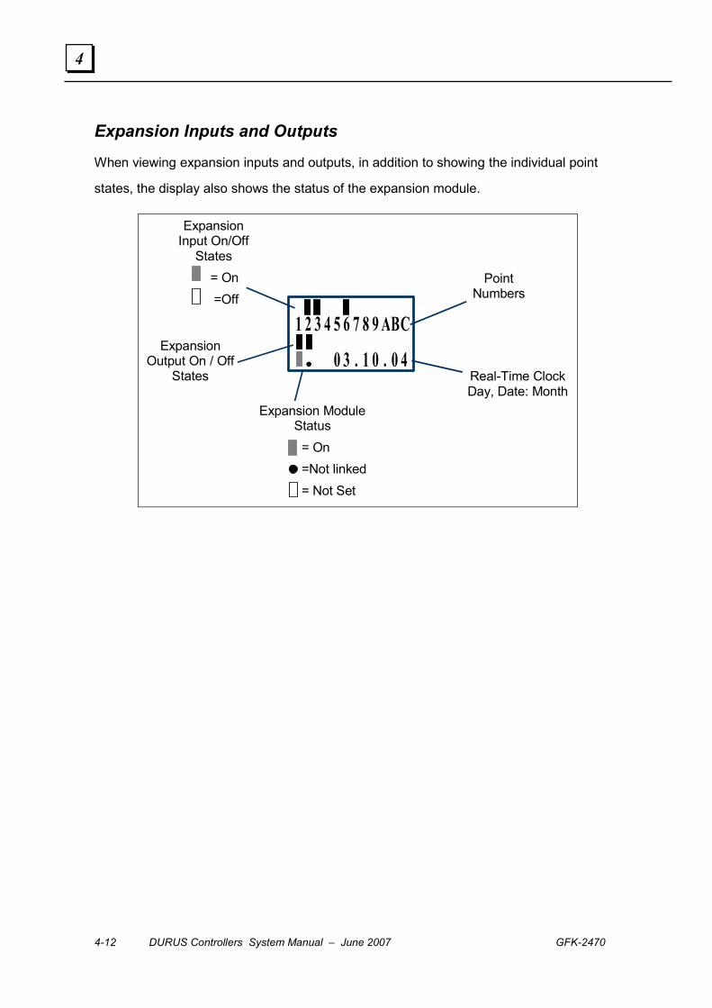
4-12 DURUS Controllers System Manual – June 2007 GFK-2470
4
Expansion Inputs and Outputs
When viewing expansion inputs and outputs, in addition to showing the individual point
states, the display also shows the status of the expansion module.
Expansion Input On/Off
States = On =Off
Expansion Output On / Off
States
Point Numbers
Real-Time Clock Day, Date: Month
1 2 3 4 5 6 7 8 9 ABC
•••• 0 3 . 1 0 . 0 4
Expansion Module Status
= On =Not linked
= Not Set
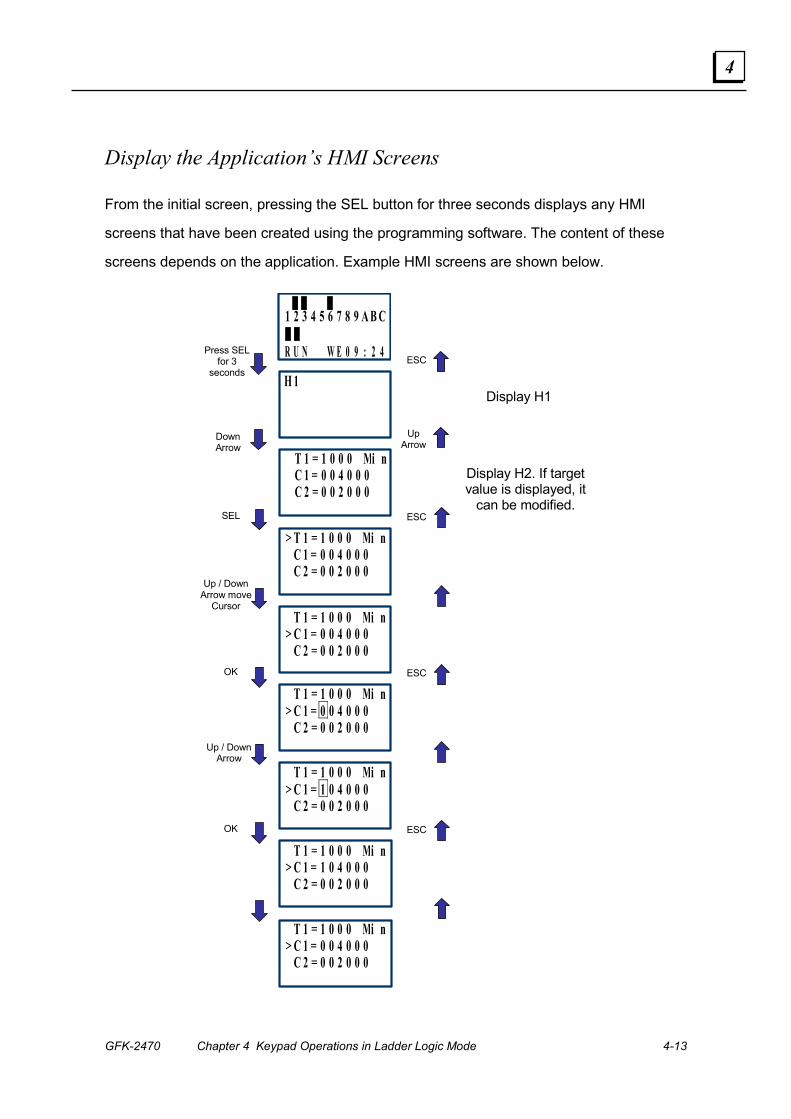
GFK-2470 Chapter 4 Keypad Operations in Ladder Logic Mode 4-13
4
Display the Application’s HMI Screens
From the initial screen, pressing the SEL button for three seconds displays any HMI
screens that have been created using the programming software. The content of these
screens depends on the application. Example HMI screens are shown below.
Press SEL for 3
seconds
1 2 3 4 5 6 7 8 9 A B C
R U N W E 0 9 : 2 4
H 1
Display H1
Display H2. If target value is displayed, it
can be modified. SEL
OK
Up / Down Arrow
OK
ESC
ESC
ESC
ESC
T 1 = 1 0 0 0 Mi n C 1 = 0 0 4 0 0 0 C 2 = 0 0 2 0 0 0
Down Arrow
Up Arrow
> T 1 = 1 0 0 0 Mi n C 1 = 0 0 4 0 0 0 C 2 = 0 0 2 0 0 0 Up / Down
Arrow move Cursor
T 1 = 1 0 0 0 Mi n> C 1 = 0 0 4 0 0 0 C 2 = 0 0 2 0 0 0
T 1 = 1 0 0 0 Mi n> C 1 = 0 0 4 0 0 0 C 2 = 0 0 2 0 0 0
T 1 = 1 0 0 0 Mi n> C 1 = 1 0 4 0 0 0 C 2 = 0 0 2 0 0 0
T 1 = 1 0 0 0 Mi n> C 1 = 1 0 4 0 0 0 C 2 = 0 0 2 0 0 0
T 1 = 1 0 0 0 Mi n> C 1 = 0 0 4 0 0 0 C 2 = 0 0 2 0 0 0
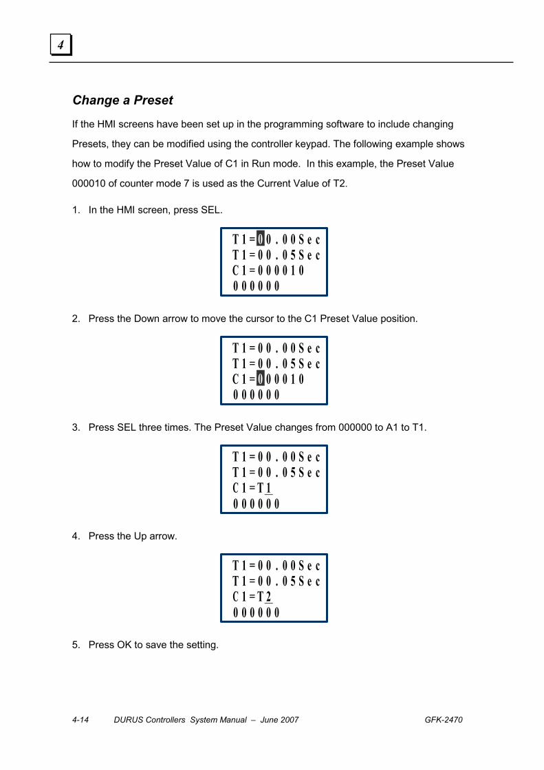
4-14 DURUS Controllers System Manual – June 2007 GFK-2470
4
Change a Preset
If the HMI screens have been set up in the programming software to include changing
Presets, they can be modified using the controller keypad. The following example shows
how to modify the Preset Value of C1 in Run mode. In this example, the Preset Value
000010 of counter mode 7 is used as the Current Value of T2.
1. In the HMI screen, press SEL.
T 1 = 0 0 . 0 0 S e cT 1 = 0 0 . 0 5 S e cC 1 = 0 0 0 0 1 00 0 0 0 0 0
2. Press the Down arrow to move the cursor to the C1 Preset Value position.
T 1 = 0 0 . 0 0 S e cT 1 = 0 0 . 0 5 S e cC 1 = 0 0 0 0 1 00 0 0 0 0 0
3. Press SEL three times. The Preset Value changes from 000000 to A1 to T1.
T 1 = 0 0 . 0 0 S e cT 1 = 0 0 . 0 5 S e cC 1 = T 10 0 0 0 0 0
4. Press the Up arrow.
T 1 = 0 0 . 0 0 S e cT 1 = 0 0 . 0 5 S e cC 1 = T 20 0 0 0 0 0
5. Press OK to save the setting.

GFK-2470 Chapter 4 Keypad Operations in Ladder Logic Mode 4-15
4
Ladder Logic Editing on the Controller
Ordinarily, ladder logic programs are created using the programming software, then stored to the controller. The program presently in the controller can be edited using the keypad as described below. For information about program functions, please refer to chapter 3.
Select Ladder from the Main Menu. In Ladder mode, the 16 horizontal positions on the screen are grouped into eight columns as shown below. Each ‘double’ column contains a character representing a program element (such as I for input), and a digit.
Keypad Functions in Ladder Mode Press Description
Ix ⇒ ix ⇒ ── ⇒ space ⇒ Ix (column 1, 3, or 5.)
Qx ⇒ space ⇒ Qx (column 8). ┬ ⇒ ┴ space ┴ ⇒ ┬ (for all except line 1, column 2, 4, or 6)
SEL
x : Digital: 1~F 1...F, ─
I ⇔ X ⇔ Q ⇔ Y⇔ M ⇔ D ⇔ T ⇔ C ⇔ R ⇔ G ⇔ I Q ⇔ Y ⇔ M ⇔ T ⇔ C ⇔ R ⇔ G ⇔H ⇔ L ⇔P ⇔ Q (Cursor in column 8) ( ⇔ � ⇔ � ⇔ P ⇔ ( Cursor at column 7 when column 8 Q, Y, or M)
SEL + Up Arrow
or Down Arrow
( ⇔ P ⇔ ( Cursor at column 7 when column 8 is set as T) SEL + ←/→ Confirm the input data and move the cursor Arrow keys Move the cursor
DEL Delete an instruction Cancel the instruction or action during editing. ESC Return to Main Menu from the program. Confirm the data and automatically save, the cursor moves to next input position.
OK
When the cursor is on Column 8, press OK to automatically enter the function block and set the parameters.
SEL+DEL Delete a line of an instruction. SEL+ESC Display the number of the lines and controller Run/Stop mode SEL+↑/ ↓ Skip up/ down every 4-line program. SEL+OK Insert a line of space

4-16 DURUS Controllers System Manual – June 2007 GFK-2470
4
Ladder Logic Entry Example Column 1 2 3 4 5 6 7 8
Line 1 > L A D D E R 2 F U N . B L O C K 3 R U N
Initial Screen, with cursor at “Ladder”
4 C L E A R P R O G .
Column 1 2 3 4 5 6 7 8 Line 1
2 3
Step 1: Press ‘OK’ to place the display in Ladder Edit mode.
4
Column 1 2 3 4 5 6 7 8 Line 1 I 1
2 3
Step 2: Press SEL with cursor located at character or digit, press the button to show I1.
4
Column 1 2 3 4 5 6 7 8 Line 1 Q 1
2 3
Step 3: Press Up Arrow twice. (Press SEL + Up / Down and the digit at the cursor position will change from I to Q). 4
Column 1 2 3 4 5 6 7 8
Line 1 q 1 2 3
Step 4: Press SEL to start /end modifying parameter.
4
Column 1 2 3 4 5 6 7 8 Line 1 q 1
2 3
Step 5: Press Right Arrow. (Press SEL + Right / Left Arrow if cursor is located on the digit position in a column). 4
Column 1 2 3 4 5 6 7 8
Line 1 q 4 2 3
Step 6: Press Up Arrow three times. (Press SEL + Up / Down Arrow, the digit will change from 1 to 4)
4

GFK-2470 Chapter 4 Keypad Operations in Ladder Logic Mode 4-17
4
Ladder Logic Example, continued Column 1 2 3 4 5 6 7 8
Line 1 q 4 2 3
Step 7: Press Left Arrow (Press SEL + Left / Right Arrow to move the cursor to the position).
4
OR Column 1 2 3 4 5 6 7 8
Line 1 q 4 2 3
Press OK to move the cursor to character in column 3.
4
OR Column 1 2 3 4 5 6 7 8
Line 1 q 4 2 3
Press Right Arrow to move the cursor to the link location in column 2.
4
Repeat steps1 to 7, and add M1 and I3 instructions to columns 3 and 5.
Column 1 2 3 4 5 6 7 8
Line 1 q 4 M 1 I 3 2 3
Step 8: Press OK in Column 5 to move the cursor to the character in column 8.
4
Column 1 2 3 4 5 6 7 8 Line 1 q 4 M 1 I 3 ( Q 1
2 3
Step 9: Press SEL (with the cursor located at character and digit, press SEL to show –( Q1)
4
Column 1 2 3 4 5 6 7 8
Line 1 q 4 M 1 I 3 ( Q 1 2 3
Step 10: Press OK to save the input program data. The cursor will not move.
4
Automatically Link
Auto Add “ -( ”
Automatically Link
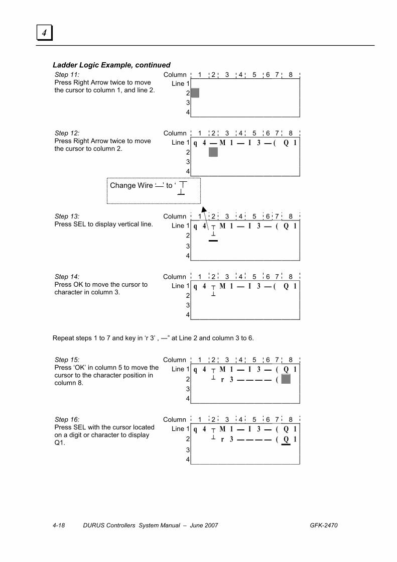
4-18 DURUS Controllers System Manual – June 2007 GFK-2470
4
Ladder Logic Example, continued Column 1 2 3 4 5 6 7 8
Line 1 2 3
Step 11: Press Right Arrow twice to move the cursor to column 1, and line 2.
4
Column 1 2 3 4 5 6 7 8 Line 1 q 4 M 1 I 3 ( Q 1
2 3
Step 12: Press Right Arrow twice to move the cursor to column 2.
4
Column 1 2 3 4 5 6 7 8 Line 1 q 4 ┬ M 1 I 3 ( Q 1
2 ┴ 3
Step 13: Press SEL to display vertical line.
4
Column 1 2 3 4 5 6 7 8 Line 1 q 4 ┬ M 1 I 3 ( Q 1
2 ┴ 3
Step 14: Press OK to move the cursor to character in column 3.
4
Repeat steps 1 to 7 and key in ‘r 3’ , ―” at Line 2 and column 3 to 6.
Column 1 2 3 4 5 6 7 8
Line 1 q 4 ┬ M 1 I 3 ( Q 1 2 ┴ r 3 ( 3
Step 15: Press ‘OK’ in column 5 to move the cursor to the character position in column 8.
4
Column 1 2 3 4 5 6 7 8 Line 1 q 4 ┬ M 1 I 3 ( Q 1
2 ┴ r 3 ( Q 1 3
Step 16: Press SEL with the cursor located on a digit or character to display Q1.
4
Change Wire ‘ ’ to ‘ ’

GFK-2470 Chapter 4 Keypad Operations in Ladder Logic Mode 4-19
4
Ladder Logic Example, continued
Column 1 2 3 4 5 6 7 8
Line 1 q 4 ┬ M 1 I 3 ( Q 1 2 ┴ r 3 ( C 1 3
Step 17: Press Up Arrow four times. (Press SEL + Up/ /Down Arrow) The character Q the cursor location changes to C. 4
Column 1 2 3 4 5 6 7 8
Line 1 q 4 ┬ M 1 I 3 ( Q 1 2 ┴ r 3 ( C 1 3
Step 18: Press Right Arrow key.
4
Column 1 2 3 4 5 6 7 8 Line 1 q 4 ┬ M 1 I 3 ( Q 1
2 ┴ r 3 ( C 7 3
Step 19 : Press Up Arrow key seven times. (Press SEL + Up / Down Arrow). The digit 1 at the cursor location changes to 7)
4
Column 1 2 3 4 5 6 7 8 Line 1 ┌ 1 ┐
2 I 1 ┤ │ 3 │ 0 0 0 0 ├ C 7
Step 20: Press OK to automatically switch to Function Block view and counter input parameter.
4 I 1 ┴ ┘
Column 1 2 3 4 5 6 7 8 Line 1 q 4 ┬ M 1 I 3 ( Q 1
2 ┴ r 3 ( C 7 3
Step 21: Press ESC to return to Ladder Logic mode.
4
Auto Enter Function
Block Edit
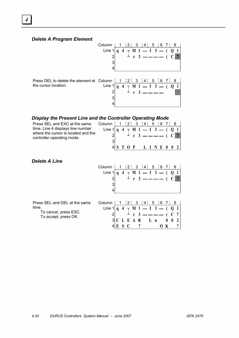
4-20 DURUS Controllers System Manual – June 2007 GFK-2470
4
Delete A Program Element Column 1 2 3 4 5 6 7 8
Line 1 q 4 ┬ M 1 I 3 ( Q 1 2 ┴ r 3 ( C 7 3
4
Column 1 2 3 4 5 6 7 8 Line 1 q 4 ┬ M 1 I 3 ( Q 1
2 ┴ r 3 3
Press DEL to delete the element at the cursor location.
4
Display the Present Line and the Controller Operating Mode Column 1 2 3 4 5 6 7 8
Line 1 q 4 ┬ M 1 I 3 ( Q 1 2 ┴ r 3 ( C 7 3
Press SEL and EXC at the same time. Line 4 displays line number where the cursor is located and the controller operating mode.
4 S T O P L I N E 0 0 2
Delete A Line Column 1 2 3 4 5 6 7 8
Line 1 q 4 ┬ M 1 I 3 ( Q 1 2 ┴ r 3 ( C 7 3
4
Column 1 2 3 4 5 6 7 8 Line 1 q 4 ┬ M 1 I 3 ( Q 1
2 ┴ r 3 ( C 7 3 C L E A R L n 0 0 2
Press SEL and DEL at the same time. To cancel, press ESC. To accept, press OK.
4 E S C ? O K ?

GFK-2470 Chapter 4 Keypad Operations in Ladder Logic Mode 4-21
4
Insert A Line Column 1 2 3 4 5 6 7 8
line 1 q 4 ┬ M 1 I 3 ( Q 1 2 ┴ r 3 ( C 7 3
4
Column 1 2 3 4 5 6 7 8 Line 1 q 4 ┬ M 1 I 3 ( Q 1
2 3 ┴ r 3 ( C 7
Press SEL and OK at the same time.
4
Move Up or Down Four Lines Column 1 2 3 4 5 6 7 8
line 1 q 4 ┬ M 1 I 3 ( Q 1 2 ┴ r 3 ( C 7 3 4
5
Column 1 2 3 4 5 6 7 8 line 1 q 4 ┬ M 1 I 3 ( Q 1
2 ┴ r 3 ( C 7 3 4
Press SEL and Up Arrow or Down Arrow at the same time.
5
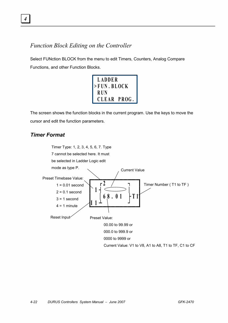
4-22 DURUS Controllers System Manual – June 2007 GFK-2470
4
Function Block Editing on the Controller
Select FUNction BLOCK from the menu to edit Timers, Counters, Analog Compare
Functions, and other Function Blocks.
L A D D E R> F U N . B L OC K
R U NC L E A R P R OG .
The screen shows the function blocks in the current program. Use the keys to move the
cursor and edit the function parameters.
Timer Format
┌┘
2 ┐ 1 ┤ │ │ 6 8 . 0 1 ├ T 1I 1 ┴ ┘
Timer Number ( T1 to TF )
Preset Value:
00.00 to 99.99 or
000.0 to 999.9 or
0000 to 9999 or
Current Value: V1 to V8, A1 to A8, T1 to TF, C1 to CF
Current Value
Timer Type: 1, 2, 3, 4, 5, 6, 7. Type
7 cannot be selected here. It must
be selected in Ladder Logic edit
mode as type P.
Preset Timebase Value:
1 = 0.01 second
2 = 0.1 second
3 = 1 second
4 = 1 minute
Reset Input

GFK-2470 Chapter 4 Keypad Operations in Ladder Logic Mode 4-23
4
Counter Format, Types 1 to 6
┌┘
6 ┐I 6 ┤ │ │ 0 1 2 3 3 3 ├ C 1I 8 ┴ ┘
If an Up Counter is selected, when the Reset Input is On, the Current Value clears to 0.
If the selected Counter Type is type 1, 2, 3, or 4 and down counting is selected, when the
Reset Input is Off, the Current Value is set to the Reset Value.
Counter Format, Type 7
┌┘
7 ┐I 1 ┤ │ │ 6 8 0 1 2 3 ├ C 1I 4 ┴ ┘
Counter Number ( C1 to CF )
Preset Value:
000000 to 999999 or
Current Value: V1 to V8, A1 to A8, T1 to TF, C1 to CF
Current Value Counter Type: 1, 2, 3, 4, 5, 6.
Up / Down
Counter set input
Reset Input
Counter Number ( C1 to CF )
Preset Value:
000000 to 999999 or
Current Value: V1 to V8, A1 to A8, T1 to TF, C1 to CF
Current Value Counter Type: 7
High-speed Set
Input: I1 or I2
Reset Input
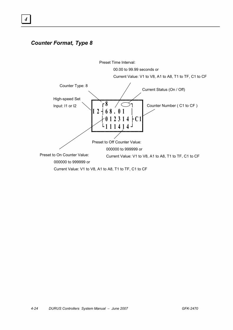
4-24 DURUS Controllers System Manual – June 2007 GFK-2470
4
Counter Format, Type 8
┌┘
8 ┐I 2 ┤ 6 8 . 0 1 │ │ 0 1 2 3 1 4 ├ C 1 └ 1 1 1 4 1 4 ┘
Counter Number ( C1 to CF )
Preset to On Counter Value:
000000 to 999999 or
Current Value: V1 to V8, A1 to A8, T1 to TF, C1 to CF
Current Status (On / Off) Counter Type: 8
High-speed Set
Input: I1 or I2
Preset Time Interval:
00.00 to 99.99 seconds or
Current Value: V1 to V8, A1 to A8, T1 to TF, C1 to CF
Preset to Off Counter Value:
000000 to 999999 or
Current Value: V1 to V8, A1 to A8, T1 to TF, C1 to CF

GFK-2470 Chapter 4 Keypad Operations in Ladder Logic Mode 4-25
4
Real Time Clock Format, Types 1 and 2
┌┘
S A─ M O ┐ 1 ┤ │ │ 0 1 : 2 3 ├ R 1 └ 1 1 : 1 4 ┘
Real Time Clock Format, Type 3
┌┘
6 8 ─ 6 1 ┐ 3 ┤ │ │ 0 1 . 2 3 ├ R 1 └ 1 1 . 1 4 ┘
Real Time Clock Format, Type 4
┌┘
S U ┐ 4 ┤ │ │ 0 7 : 1 1 ├ R 1 └ : 2 0 ┘
Week On / Off setting
RTC Number ( R1 to RF )
Preset On Value (On time setting):
00:00 to 23:59
Current Value
RTC Type: 1 or 2
Preset Off Value (Off time setting):
00:00 to 23:59
Year On / Off setting
RTC Number ( R1 to RF )
Preset On Value (Month and Date):
01.01 to 12.31
Current Value
RTC Type: 3
Preset Off Value (Month and Date):
01.01 to 12.31
Week Set (On)
RTC Number ( R1 to RF )
Preset On Value (Time):
00:00 to 23:59
Current Value
RTC Type: 4
Preset On Value (Seconds):
00 to 59
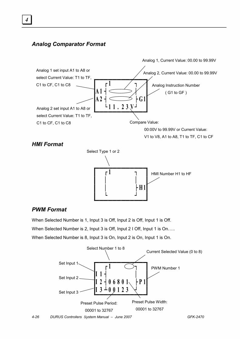
4-26 DURUS Controllers System Manual – June 2007 GFK-2470
4
Analog Comparator Format
┌┘
1 ┐A 1 ┤ │A 2 ┤ ├ G 1 └ 1 1 . 2 3 V┘
HMI Format
┌┘
1 ┐ │ │ │ ├ H 1 └ ┘
PWM Format
When Selected Number is 1, Input 3 is Off, Input 2 is Off, Input 1 is Off.
When Selected Number is 2, Input 3 is Off, Input 2 I Off, Input 1 is On…..
When Selected Number is 8, Input 3 is On, Input 2 is On, Input 1 is On.
┌┘
1 ┐I 1 ┤ │I 2 ┤ 0 6 8 0 1 ├ P 1I 3 ┴ 0 0 1 2 3 ┘
Analog Instruction Number
( G1 to GF )
Analog 1, Current Value: 00.00 to 99.99V
Analog 1 set input A1 to A8 or
select Current Value: T1 to TF,
C1 to CF, C1 to C8
Compare Value:
00:00V to 99.99V or Current Value:
V1 to V8, A1 to A8, T1 to TF, C1 to CF
Analog 2, Current Value: 00.00 to 99.99V
Analog 2 set input A1 to A8 or
select Current Value: T1 to TF,
C1 to CF, C1 to C8
Select Number 1 to 8
PWM Number 1
Preset Pulse Width:
00001 to 32767
Current Selected Value (0 to 8)
Set Input 1
Set Input 2
Set Input 3
Preset Pulse Period:
00001 to 32767
Select Type 1 or 2
HMI Number H1 to HF
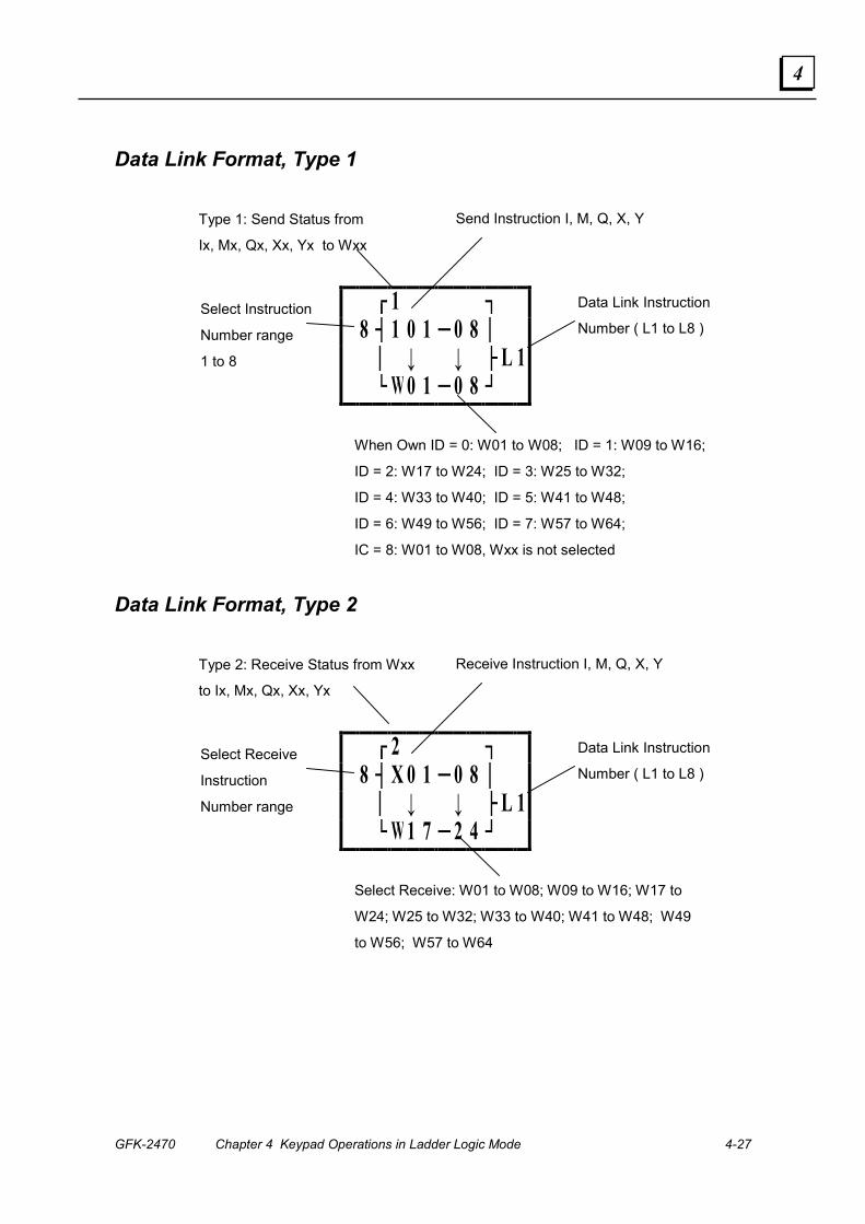
GFK-2470 Chapter 4 Keypad Operations in Ladder Logic Mode 4-27
4
Data Link Format, Type 1
┌┘
1 ┐ 8 ┤ 1 0 1 ─ 0 8 │ │ ↓ ↓ ├ L 1 └ W 0 1 ─ 0 8 ┘
Data Link Format, Type 2
┌┘
2 ┐ 8 ┤ X 0 1 ─ 0 8 │ │ ↓ ↓ ├ L 1 └ W 1 7 ─ 2 4 ┘
Type 1: Send Status from
Ix, Mx, Qx, Xx, Yx to Wxx
Data Link Instruction
Number ( L1 to L8 )
When Own ID = 0: W01 to W08; ID = 1: W09 to W16;
ID = 2: W17 to W24; ID = 3: W25 to W32;
ID = 4: W33 to W40; ID = 5: W41 to W48;
ID = 6: W49 to W56; ID = 7: W57 to W64;
IC = 8: W01 to W08, Wxx is not selected
Select Instruction
Number range
1 to 8
Send Instruction I, M, Q, X, Y
Type 2: Receive Status from Wxx
to Ix, Mx, Qx, Xx, Yx
Data Link Instruction
Number ( L1 to L8 )
Select Receive: W01 to W08; W09 to W16; W17 to
W24; W25 to W32; W33 to W40; W41 to W48; W49
to W56; W57 to W64
Select Receive
Instruction
Number range
Receive Instruction I, M, Q, X, Y

4-28 DURUS Controllers System Manual – June 2007 GFK-2470
4
GFK-2470 5-1
Software Operation in Ladder Logic Mode
The programming software has two separate programming modes: Ladder Logic and
Function Block Diagram. After the Ladder Logic or Function Block Diagram mode is
selected on the software startup screen, all software operations continue in that mode.
This chapter explains how use the programming software for programming, simulation,
and emulation in Ladder Logic mode. Similar instructions for using Function Block
Diagram mode are in chapter 7.
▪ Using the Ladder Logic Programming Software ▪ File menu functions ▪ Edit menu functions ▪ Operation menu functions ▪ View menu functions
▪ Editing Ladder Logic with the Programming Software ▪ Enter or edit an Instruction
▪ Using the Ladder Logic Software in Keypad Mode ▪ Button Functions in Keypad Mode ▪ Using the Computer Keyboard for Keypad Operations
Chapter
5

5-2 DURUS Controllers System Manual – June 2007 GFK-2470
5
Using the Ladder Logic Programming Software
The main Ladder Logic toolbar functions are shown below. Functions that are not currently
accessible are grayed out on the software screen. Functions can also be selected using
the pulldown menus as described on the following pages.
Create new Program File
Open existing Program File
Save the current Program File
Print a Program
Print Preview
Use Controller Keypad for programming / editing
Use the software for Ladder Logic programming / editing
Program / edit the HMI function
Edit Ladder screen using Instruction Symbol
Use Software to monitor instructions and functions
Test and debug the program
Place the controller in Run mode
Place the controller in Stop mode
End Monitor / Simulation mode and start Program mode
Read the program from the controller
Write a program to the controller
Open the online help
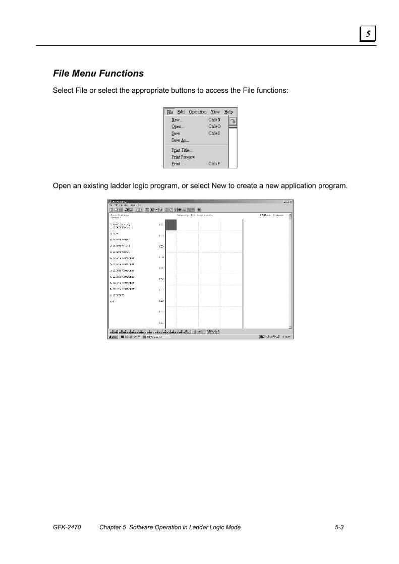
GFK-2470 Chapter 5 Software Operation in Ladder Logic Mode 5-3
5
File Menu Functions Select File or select the appropriate buttons to access the File functions:
Open an existing ladder logic program, or select New to create a new application program.
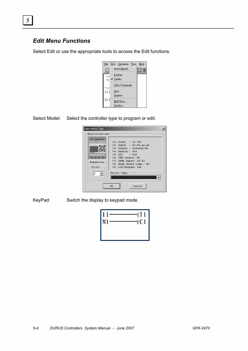
5-4 DURUS Controllers System Manual – June 2007 GFK-2470
5
Edit Menu Functions Select Edit or use the appropriate tools to access the Edit functions.
Select Model: Select the controller type to program or edit.
KeyPad: Switch the display to keypad mode.
I 1 ( T 1M 1 ( C 1
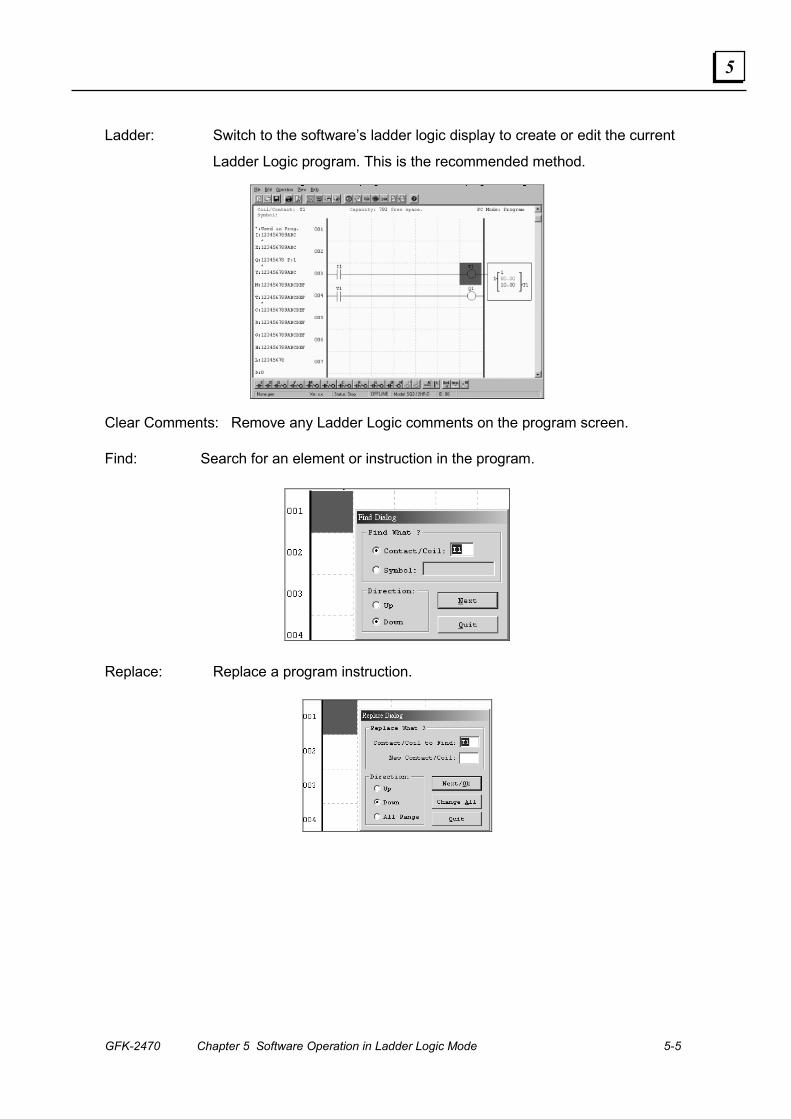
GFK-2470 Chapter 5 Software Operation in Ladder Logic Mode 5-5
5
Ladder: Switch to the software’s ladder logic display to create or edit the current
Ladder Logic program. This is the recommended method.
Clear Comments: Remove any Ladder Logic comments on the program screen.
Find: Search for an element or instruction in the program.
Replace: Replace a program instruction.
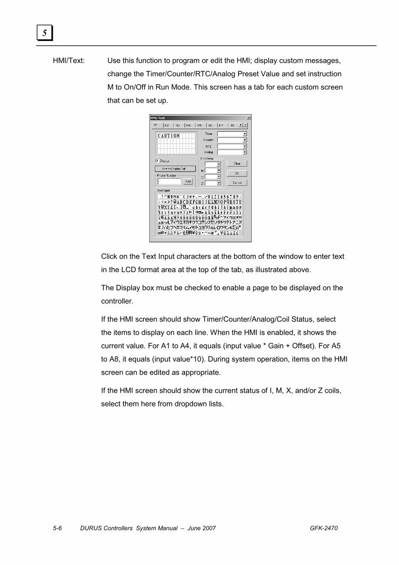
5-6 DURUS Controllers System Manual – June 2007 GFK-2470
5
HMI/Text: Use this function to program or edit the HMI; display custom messages,
change the Timer/Counter/RTC/Analog Preset Value and set instruction
M to On/Off in Run Mode. This screen has a tab for each custom screen
that can be set up.
Click on the Text Input characters at the bottom of the window to enter text
in the LCD format area at the top of the tab, as illustrated above.
The Display box must be checked to enable a page to be displayed on the
controller.
If the HMI screen should show Timer/Counter/Analog/Coil Status, select
the items to display on each line. When the HMI is enabled, it shows the
current value. For A1 to A4, it equals (input value * Gain + Offset). For A5
to A8, it equals (input value*10). During system operation, items on the HMI
screen can be edited as appropriate.
If the HMI screen should show the current status of I, M, X, and/or Z coils,
select them here from dropdown lists.
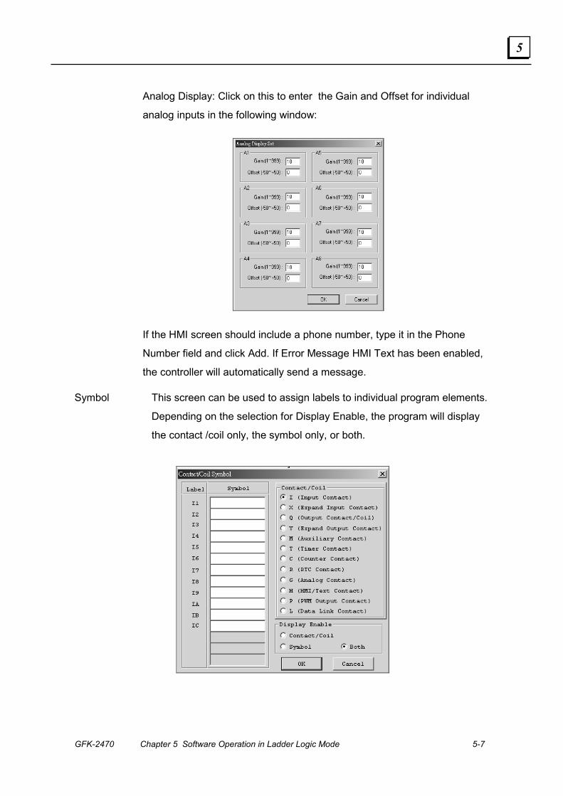
GFK-2470 Chapter 5 Software Operation in Ladder Logic Mode 5-7
5
Analog Display: Click on this to enter the Gain and Offset for individual
analog inputs in the following window:
If the HMI screen should include a phone number, type it in the Phone
Number field and click Add. If Error Message HMI Text has been enabled,
the controller will automatically send a message.
Symbol This screen can be used to assign labels to individual program elements.
Depending on the selection for Display Enable, the program will display
the contact /coil only, the symbol only, or both.
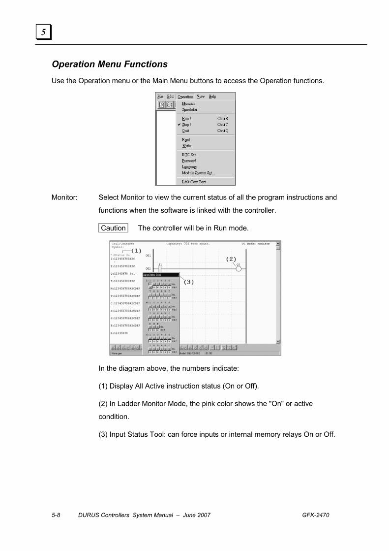
5-8 DURUS Controllers System Manual – June 2007 GFK-2470
5
Operation Menu Functions Use the Operation menu or the Main Menu buttons to access the Operation functions.
Monitor: Select Monitor to view the current status of all the program instructions and
functions when the software is linked with the controller.
Caution The controller will be in Run mode.
In the diagram above, the numbers indicate:
(1) Display All Active instruction status (On or Off).
(2) In Ladder Monitor Mode, the pink color shows the "On" or active
condition.
(3) Input Status Tool: can force inputs or internal memory relays On or Off.
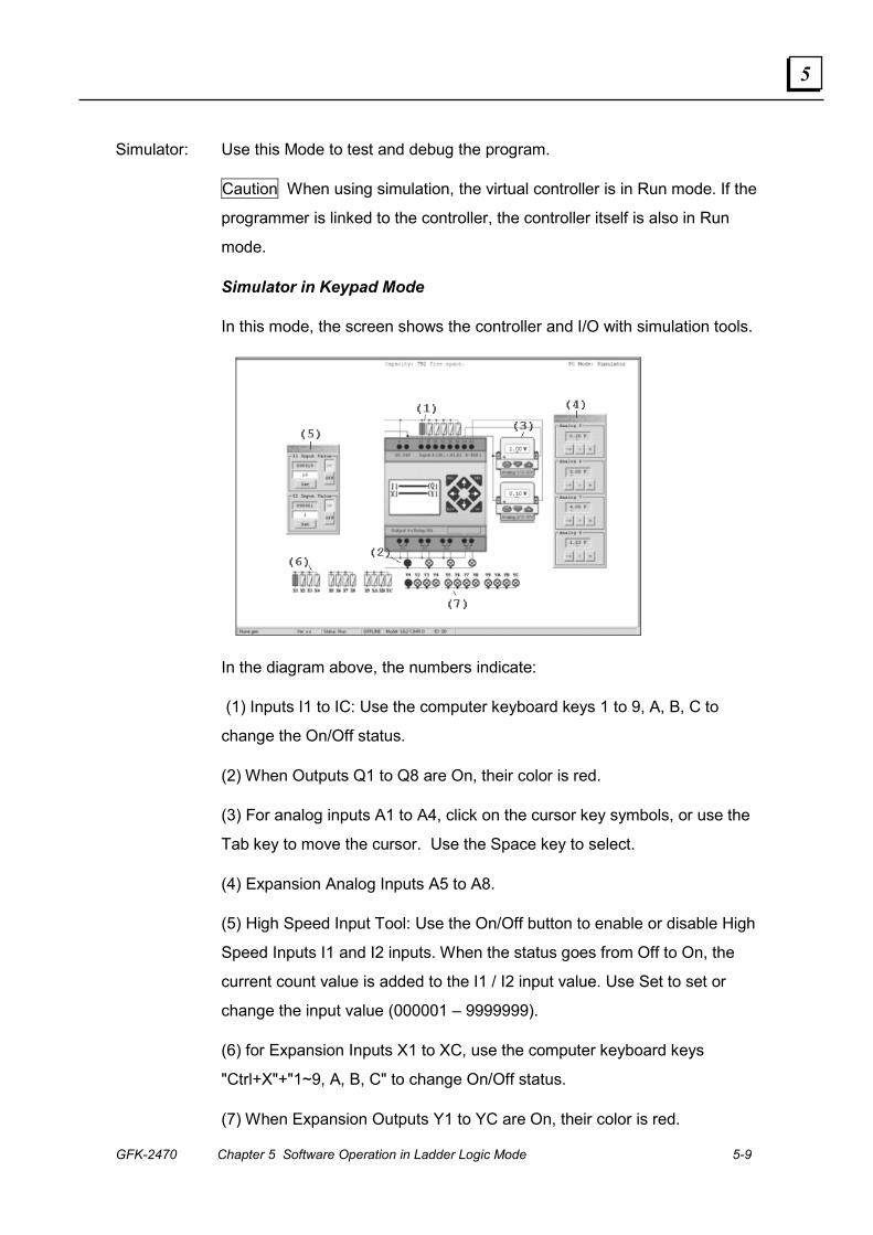
GFK-2470 Chapter 5 Software Operation in Ladder Logic Mode 5-9
5
Simulator: Use this Mode to test and debug the program.
Caution When using simulation, the virtual controller is in Run mode. If the
programmer is linked to the controller, the controller itself is also in Run
mode.
Simulator in Keypad Mode
In this mode, the screen shows the controller and I/O with simulation tools.
In the diagram above, the numbers indicate:
(1) Inputs I1 to IC: Use the computer keyboard keys 1 to 9, A, B, C to
change the On/Off status.
(2) When Outputs Q1 to Q8 are On, their color is red.
(3) For analog inputs A1 to A4, click on the cursor key symbols, or use the
Tab key to move the cursor. Use the Space key to select.
(4) Expansion Analog Inputs A5 to A8.
(5) High Speed Input Tool: Use the On/Off button to enable or disable High
Speed Inputs I1 and I2 inputs. When the status goes from Off to On, the
current count value is added to the I1 / I2 input value. Use Set to set or
change the input value (000001 – 9999999).
(6) for Expansion Inputs X1 to XC, use the computer keyboard keys
"Ctrl+X"+"1~9, A, B, C" to change On/Off status.
(7) When Expansion Outputs Y1 to YC are On, their color is red.
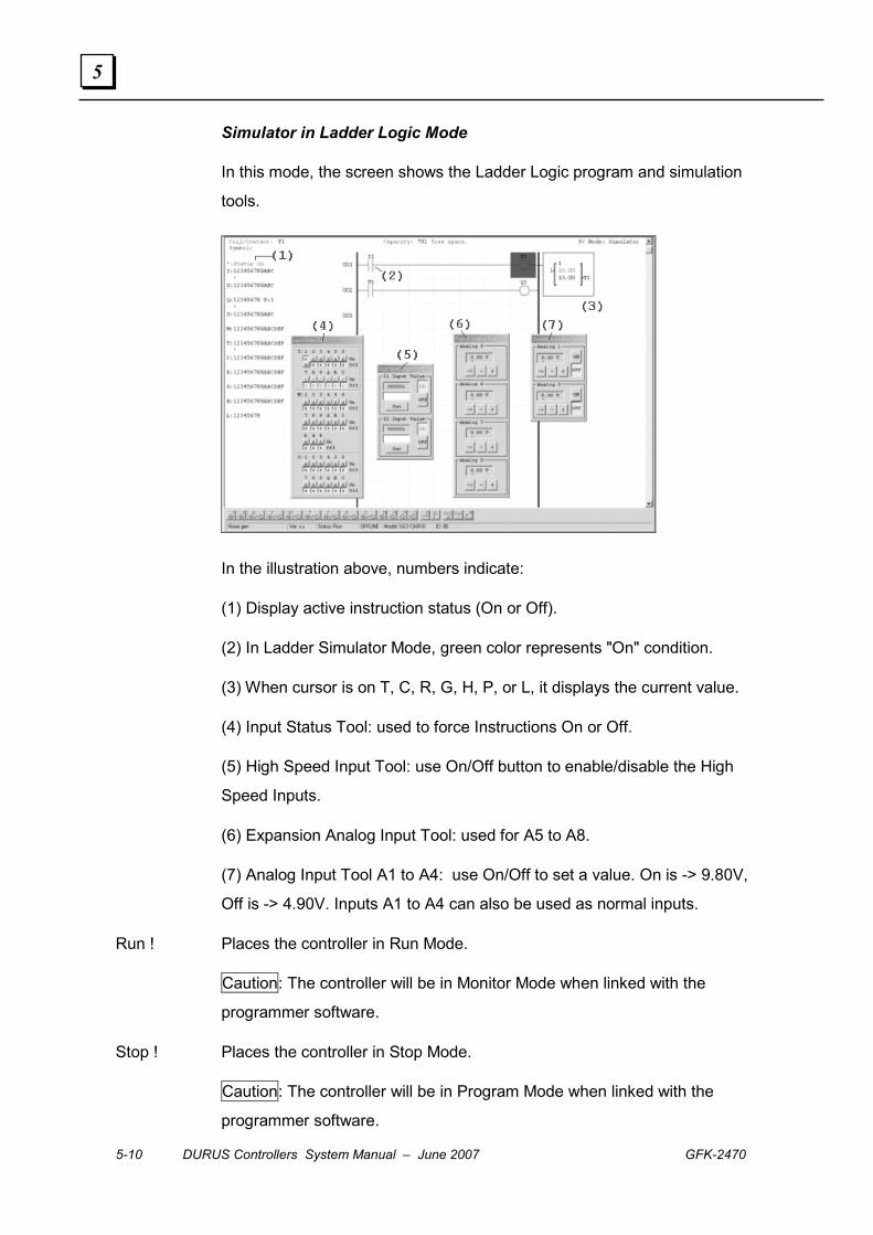
5-10 DURUS Controllers System Manual – June 2007 GFK-2470
5
Simulator in Ladder Logic Mode
In this mode, the screen shows the Ladder Logic program and simulation
tools.
In the illustration above, numbers indicate:
(1) Display active instruction status (On or Off).
(2) In Ladder Simulator Mode, green color represents "On" condition.
(3) When cursor is on T, C, R, G, H, P, or L, it displays the current value.
(4) Input Status Tool: used to force Instructions On or Off.
(5) High Speed Input Tool: use On/Off button to enable/disable the High
Speed Inputs.
(6) Expansion Analog Input Tool: used for A5 to A8.
(7) Analog Input Tool A1 to A4: use On/Off to set a value. On is -> 9.80V,
Off is -> 4.90V. Inputs A1 to A4 can also be used as normal inputs.
Run ! Places the controller in Run Mode.
Caution: The controller will be in Monitor Mode when linked with the
programmer software.
Stop ! Places the controller in Stop Mode.
Caution: The controller will be in Program Mode when linked with the
programmer software.
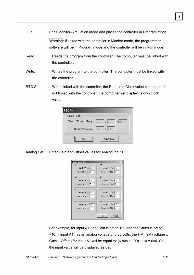
GFK-2470 Chapter 5 Software Operation in Ladder Logic Mode 5-11
5
Quit Ends Monitor/Simulation mode and places the controller in Program mode.
Warning: If linked with the controller in Monitor mode, the programmer
software will be in Program mode and the controller will be in Run mode.
Read: Reads the program from the controller. The computer must be linked with
the controller.
Write: Writes the program to the controller. The computer must be linked with
the controller.
RTC Set: When linked with the controller, the Real-time Clock value can be set. If
not linked with the controller, the computer will display its own clock
value.
Analog Set: Enter Gain and Offset values for Analog inputs.
For example, for input A1, the Gain is set to 100 and the Offset is set to
+10. If input A1 has an analog voltage of 6.80 volts, the HMI text (voltage x
Gain + Offset) for input A1 will be equal to: (6.80V * 100) + 10 = 690. So
the input value will be displayed as 690.
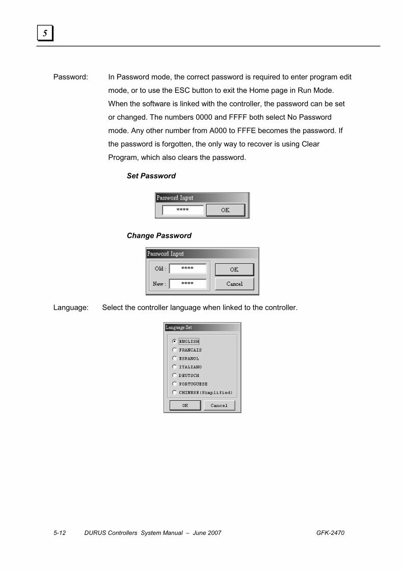
5-12 DURUS Controllers System Manual – June 2007 GFK-2470
5
Password: In Password mode, the correct password is required to enter program edit
mode, or to use the ESC button to exit the Home page in Run Mode.
When the software is linked with the controller, the password can be set
or changed. The numbers 0000 and FFFF both select No Password
mode. Any other number from A000 to FFFE becomes the password. If
the password is forgotten, the only way to recover is using Clear
Program, which also clears the password.
Set Password
Change Password
Language: Select the controller language when linked to the controller.
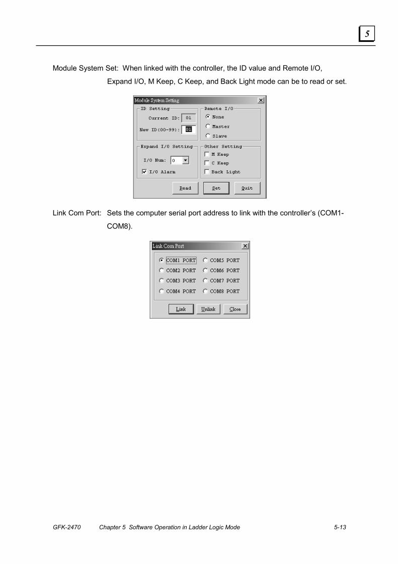
GFK-2470 Chapter 5 Software Operation in Ladder Logic Mode 5-13
5
Module System Set: When linked with the controller, the ID value and Remote I/O,
Expand I/O, M Keep, C Keep, and Back Light mode can be to read or set.
Link Com Port: Sets the computer serial port address to link with the controller’s (COM1-
COM8).

5-14 DURUS Controllers System Manual – June 2007 GFK-2470
5
View Menu Functions The View menu controls what appears on the software screens.
I/O: In Ladder Logic Edit screen and in Program Mode, displays or hides
instructions used in the program.
Function: Moving the cursor onto a function displays the Current and Preset Value.
Capacity: Displays the controller ‘s available program memory.
Input Status Tool: Can be used by the controller in Monitor or Simulation Mode. In
Simulation mode, can turn I , X, and M points On or Off. In Monitor
mode, can turn only M points On or Off.
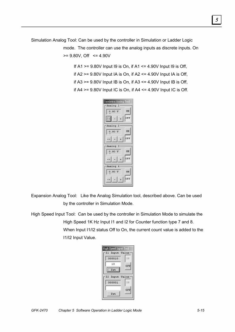
GFK-2470 Chapter 5 Software Operation in Ladder Logic Mode 5-15
5
Simulation Analog Tool: Can be used by the controller in Simulation or Ladder Logic
mode. The controller can use the analog inputs as discrete inputs. On
>= 9.80V, Off <= 4.90V
If A1 >= 9.80V Input I9 is On, if A1 <= 4.90V Input I9 is Off,
if A2 >= 9.80V Input IA is On, if A2 <= 4.90V Input IA is Off,
if A3 >= 9.80V Input IB is On, if A3 <= 4.90V Input IB is Off,
if A4 >= 9.80V Input IC is On, if A4 <= 4.90V Input IC is Off.
Expansion Analog Tool: Like the Analog Simulation tool, described above. Can be used
by the controller in Simulation Mode.
High Speed Input Tool: Can be used by the controller in Simulation Mode to simulate the
High Speed 1K Hz Input I1 and I2 for Counter function type 7 and 8.
When Input I1/I2 status Off to On, the current count value is added to the
I1/I2 Input Value.
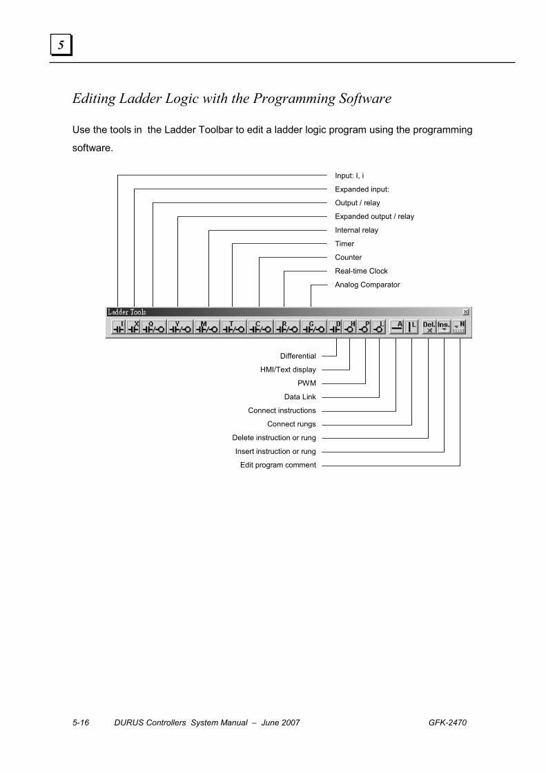
5-16 DURUS Controllers System Manual – June 2007 GFK-2470
5
Editing Ladder Logic with the Programming Software
Use the tools in the Ladder Toolbar to edit a ladder logic program using the programming
software.
Input: I, i
Expanded input:
Output / relay
Expanded output / relay
Internal relay
Timer
Counter
Real-time Clock
Analog Comparator
Differential
HMI/Text display
PWM
Data Link
Connect instructions
Connect rungs
Delete instruction or rung
Insert instruction or rung
Edit program comment

GFK-2470 Chapter 5 Software Operation in Ladder Logic Mode 5-17
5
Enter or Edit an Instruction To modify an instruction in a Ladder Logic program, double-click on the instruction or
press the keyboard Space key. Enter the parameters of the function. Examples:
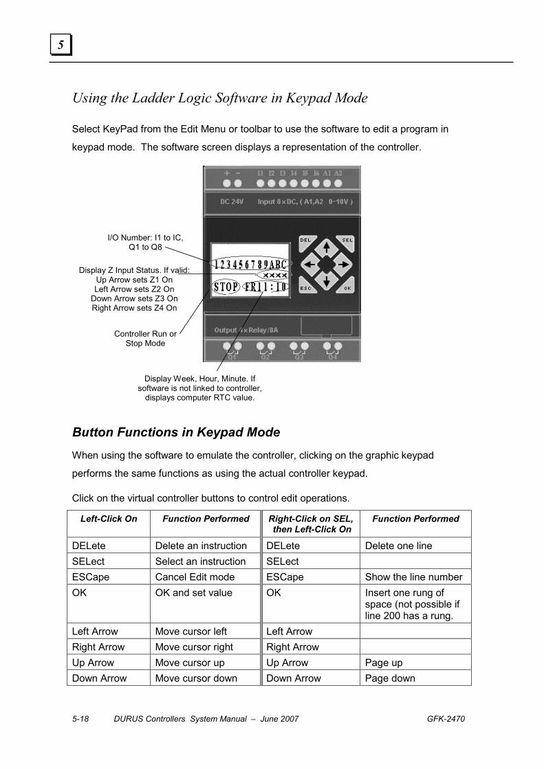
5-18 DURUS Controllers System Manual – June 2007 GFK-2470
5
Using the Ladder Logic Software in Keypad Mode
Select KeyPad from the Edit Menu or toolbar to use the software to edit a program in
keypad mode. The software screen displays a representation of the controller.
I/O Number: I1 to IC, Q1 to Q8
Controller Run or Stop Mode
Display Z Input Status. If valid: Up Arrow sets Z1 On Left Arrow sets Z2 On
Down Arrow sets Z3 On Right Arrow sets Z4 On
Display Week, Hour, Minute. If software is not linked to controller,
displays computer RTC value.
Button Functions in Keypad Mode When using the software to emulate the controller, clicking on the graphic keypad
performs the same functions as using the actual controller keypad.
Click on the virtual controller buttons to control edit operations.
Left-Click On Function Performed Right-Click on SEL, then Left-Click On
Function Performed
DELete Delete an instruction DELete Delete one line SELect Select an instruction SELect ESCape Cancel Edit mode ESCape Show the line number OK OK and set value OK Insert one rung of
space (not possible if line 200 has a rung.
Left Arrow Move cursor left Left Arrow Right Arrow Move cursor right Right Arrow Up Arrow Move cursor up Up Arrow Page up Down Arrow Move cursor down Down Arrow Page down
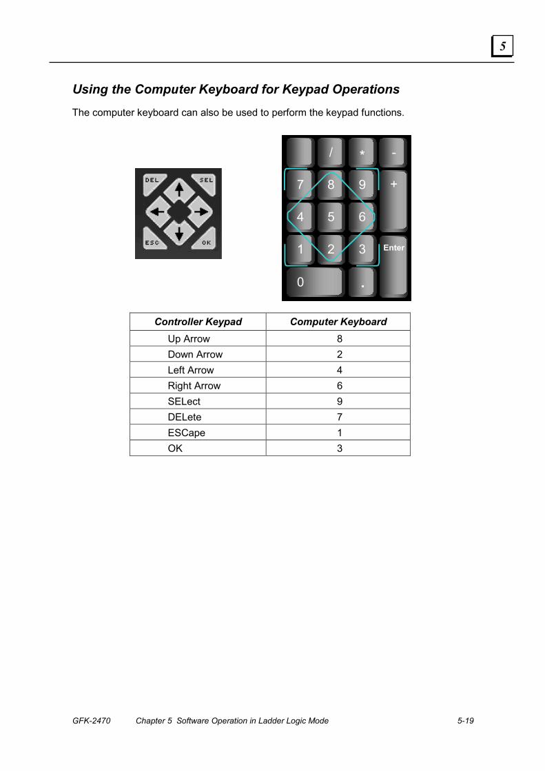
GFK-2470 Chapter 5 Software Operation in Ladder Logic Mode 5-19
5
Using the Computer Keyboard for Keypad Operations The computer keyboard can also be used to perform the keypad functions.
/
7 8
4 5
1 2
- *
9
.
6
3
0
+
Enter
Controller Keypad Computer Keyboard Up Arrow 8 Down Arrow 2 Left Arrow 4 Right Arrow 6 SELect 9 DELete 7 ESCape 1 OK 3

5-20 DURUS Controllers System Manual – June 2007 GFK-2470
5
GFK-2470 6-1
Keypad Operations in Function Block Mode
This chapter explains how navigate the controller LCD screens and make changes using the controller keypad, in Function Block mode.
▪ Startup Screen
▪ Controller Main Menu in Function Block Mode
▪ Edit Function Blocks
▪ Edit Parameters
▪ Run/Stop the Controller
▪ Clear the Current Program
▪ Write a Program
▪ Read a Program
▪ Change the Controller Setup
▪ Set the Real-time Clock
▪ Enter Analog Gain and Offsett
▪ Set or Change a Password
▪ Change the Display Language
▪ View Point States
▪ Display the Application’s HMI Screens
▪ Block Diagram Editing on the Controller
▪ Editing Coils and Contacts
▪ Editing Logic Blocks
▪ Editing Function Blocks
▪ Parameter Editing on the Controller
Chapter
6

6-2 DURUS Controllers System Manual – June 2007 GFK-2470
6
Startup Screen By default, the controller LCD screen shows:
Input On / Off States
= On =Off
Run / Stop Mode
Output On / Off States
Point Numbers
Real-Time Clock Day, Date: Month
Use the module keypad to navigate and edit the display:
ESC Return to Main Menu
↑ ↓ In Function Block Mode, display the state of other relays as shown on the next page.
SEL H Function are displayed if the SEL button is pressed for 3 seconds. If Mode 2 is selected for HMI, the H Function is not displayed.

GFK-2470 Chapter 6 Keypad Operations in Function Block Mode 6-3
6
Controller Main Menu in Function Block Mode Pressing the ESC button from the initial screen displays the Main Menu.
The controller permits more operations in Stop mode than in Run mode, as shown below. If the program in the controller is modified, the controller automatically saves changes to its internal EEPROM, not to the optional Memory Module. Saving a program to the Memory Module must be selected from the Main Menu.
� Use the Up arrow and Down arrow keys to select items from the Main Menu. � Press OK to confirm a selection. � Use the ESC key to go back to the initial screen.
Main Menu with the Controller in Stop mode:
> F U N B L OC K
P A R A ME T E R
R U N
C L E A R P R OG . Clear program AND password
WR I T E Save Program to Memory Module
R E A D Read Program from Memory Module
S E T
R T C S E T
A N A L OG S E T
P A S S WOR D
L A N GU A GE Select the Language
I N I T I A L Set initial Edit Method
Main Menu with the Controller in Run mode:
> F U N B L OC K
P A R A ME T E R
S T OP
WR I T E
R T C S E T
P A S S WOR D
L A N GU A GE
↑ ↓ Move the Cursor to select the Main Menu Items OK Confirm to enter the selected items
ESC Back to original screen

6-4 DURUS Controllers System Manual – June 2007 GFK-2470
6
Edit Function Blocks Select FUNctionBLOCK and press OK. See Function Block Editing on the Controller later in this chapter for instructions.
Edit Parameters Select PARAMETER from the menu to edit block parameters. See Parameter Editing on the Controller later in this chapter for instructions.
Run / Stop the Controller Select RUN or STOP from the menu to set the controller mode.
F U N B L OC KP A R A ME T E R
> R U NC L E A R P R OG .
Selecting RUN places the controller in Run mode. Selecting STOP places the controller in Stop mode.
Clear the Current Program In Stop mode, select Clear Program from the menu to clear the program and passwords. This function can only be used in Stop mode.
F U N B L OC KP A R A ME T E RR U N
> C L E A R P R OG .
Write a Program Select Write from the menu (by scrolling down) to write the program from the controller to the Memory Option Module.
P A R A ME T E RR U NC L E A R P R OG .
> WR I T E
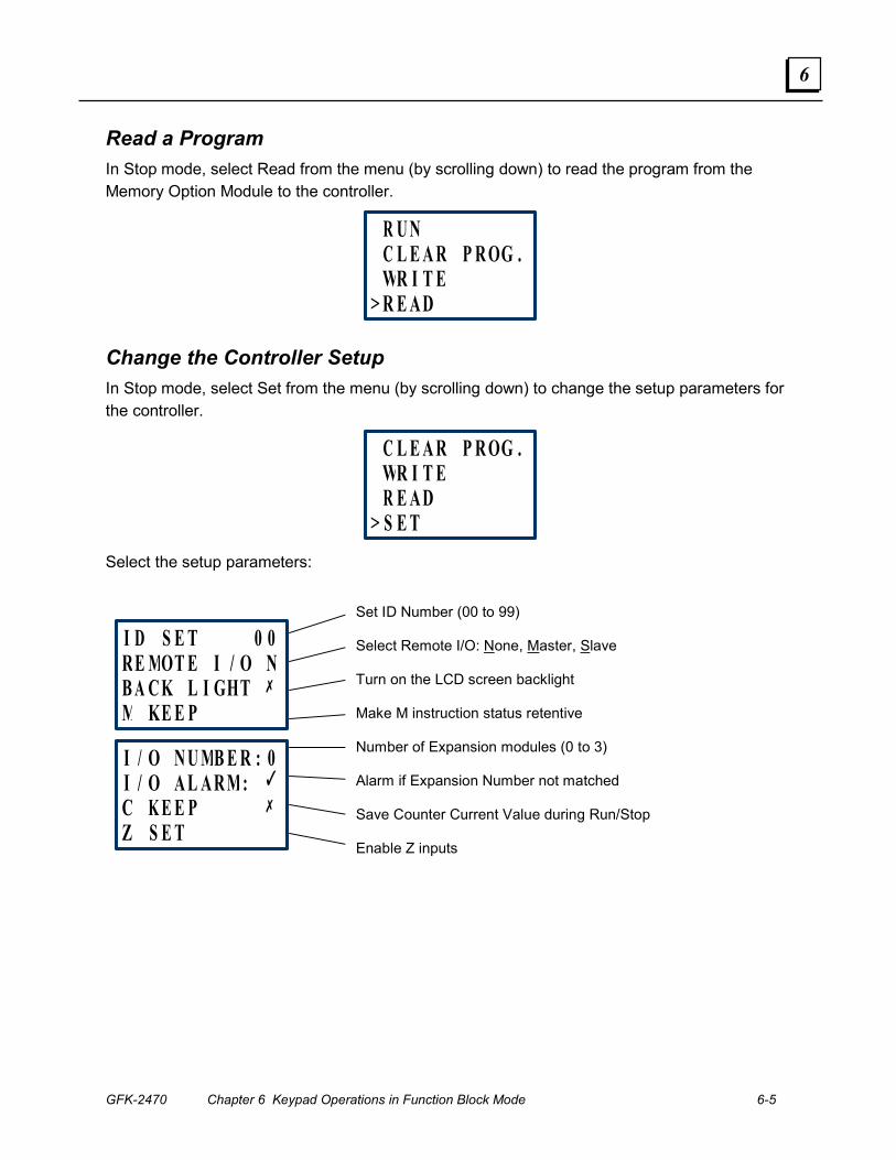
GFK-2470 Chapter 6 Keypad Operations in Function Block Mode 6-5
6
Read a Program In Stop mode, select Read from the menu (by scrolling down) to read the program from the Memory Option Module to the controller.
R U NC L E A R P R OG .WR I T E
> R E A D
Change the Controller Setup In Stop mode, select Set from the menu (by scrolling down) to change the setup parameters for the controller.
C L E A R P R OG .WR I T ER E A D
> S E T
Select the setup parameters:
I D S E T 0 0 RE MOT E I / O NB A C K L I GHT ✗
M KE E P
I / O N U MB E R : 0 I / O A L A R M: �
C K E E P ✗
Z S E T
Set ID Number (00 to 99)
Select Remote I/O: None, Master, Slave
Turn on the LCD screen backlight
Make M instruction status retentive
Number of Expansion modules (0 to 3)
Alarm if Expansion Number not matched
Save Counter Current Value during Run/Stop
Enable Z inputs
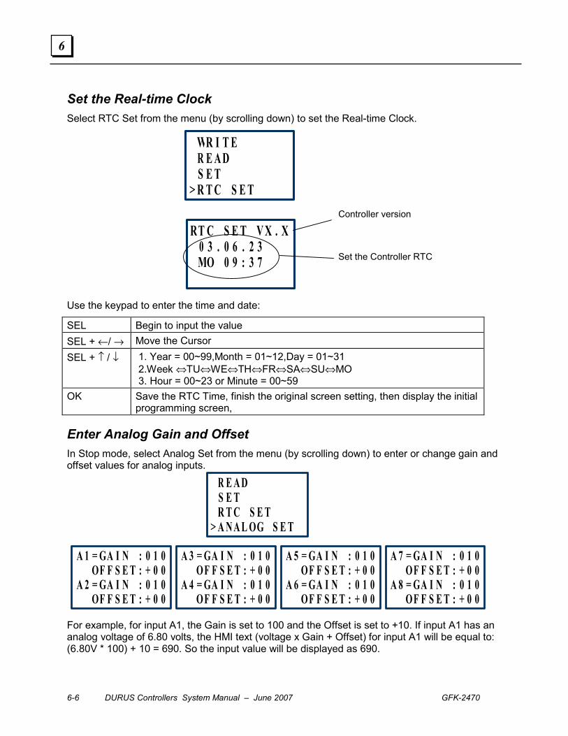
6-6 DURUS Controllers System Manual – June 2007 GFK-2470
6
Set the Real-time Clock Select RTC Set from the menu (by scrolling down) to set the Real-time Clock.
WR I T E R E A D S E T
> R T C S E T
RT C S E T V X . X 0 3 . 0 6 . 2 3 MO 0 9 : 3 7
Controller version
Set the Controller RTC
Use the keypad to enter the time and date:
SEL Begin to input the value SEL + ←/ → Move the Cursor SEL + ↑ / ↓ 1. Year = 00~99,Month = 01~12,Day = 01~31
2.Week ⇔TU⇔WE⇔TH⇔FR⇔SA⇔SU⇔MO 3. Hour = 00~23 or Minute = 00~59
OK Save the RTC Time, finish the original screen setting, then display the initial programming screen,
Enter Analog Gain and Offset In Stop mode, select Analog Set from the menu (by scrolling down) to enter or change gain and offset values for analog inputs.
R E A D S E T R T C S E T
> A N A L OG S E T
A 1 = GA I N : 0 1 0 OF F S E T : + 0 0
A 2 = GA I N : 0 1 0 OF F S E T : + 0 0
A 3 = GA I N : 0 1 0 OF F S E T : + 0 0
A 4 = GA I N : 0 1 0 OF F S E T : + 0 0
A 5 = GA I N : 0 1 0OF F S E T : + 0 0
A 6 = GA I N : 0 1 0OF F S E T : + 0 0
A 7 = GA I N : 0 1 0 OF F S E T : + 0 0
A 8 = GA I N : 0 1 0 OF F S E T : + 0 0
For example, for input A1, the Gain is set to 100 and the Offset is set to +10. If input A1 has an analog voltage of 6.80 volts, the HMI text (voltage x Gain + Offset) for input A1 will be equal to: (6.80V * 100) + 10 = 690. So the input value will be displayed as 690.
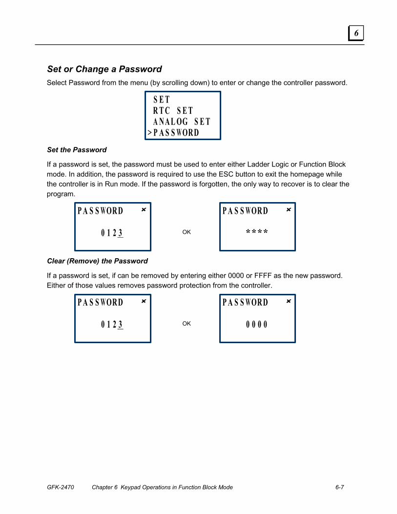
GFK-2470 Chapter 6 Keypad Operations in Function Block Mode 6-7
6
Set or Change a Password Select Password from the menu (by scrolling down) to enter or change the controller password.
S E T R T C S E T A N A L OG S E T
> P A S S WOR D
Set the Password
If a password is set, the password must be used to enter either Ladder Logic or Function Block mode. In addition, the password is required to use the ESC button to exit the homepage while the controller is in Run mode. If the password is forgotten, the only way to recover is to clear the program.
P A S S WOR D ✘
0 1 2 3
P A S S WOR D ✘
****
OK
Clear (Remove) the Password
If a password is set, if can be removed by entering either 0000 or FFFF as the new password. Either of those values removes password protection from the controller.
P A S S WOR D ✘
0 1 2 3
P A S S WOR D ✘
0 0 0 0
OK
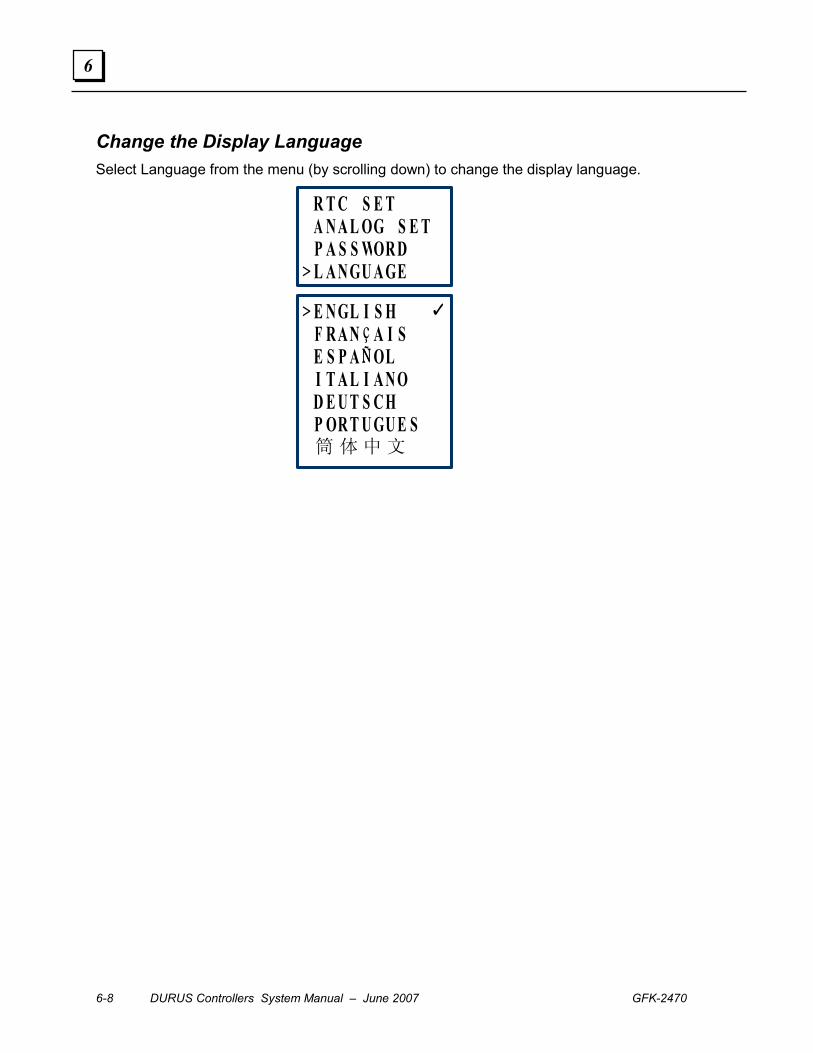
6-8 DURUS Controllers System Manual – June 2007 GFK-2470
6
Change the Display Language Select Language from the menu (by scrolling down) to change the display language.
R T C S E T A N A L OG S E T P A S S WOR D
> L A N GU A GE
> E N GL I S H �
F R A N ç A I S E S P A ÑÑÑÑ OL I T A L I A N O D E U T S C H P OR T U GU E S 筒 体 中 文
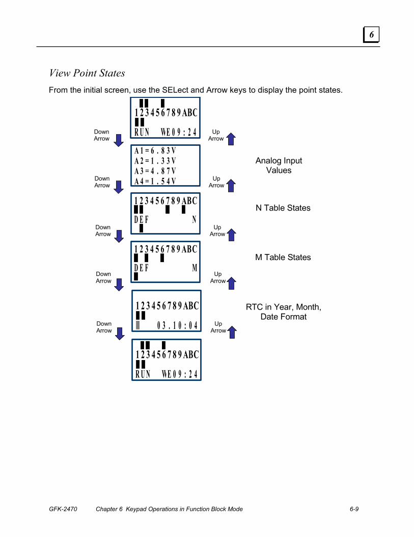
GFK-2470 Chapter 6 Keypad Operations in Function Block Mode 6-9
6
View Point States From the initial screen, use the SELect and Arrow keys to display the point states.
Down Arrow
1 2 3 4 5 6 7 8 9 ABC
R U N WE 0 9 : 2 4A 1 = 6 . 8 3 VA 2 = 1 . 3 3 VA 3 = 4 . 8 7 VA 4 = 1 . 5 4 V
1 2 3 4 5 6 7 8 9 ABC
D E F N
1 2 3 4 5 6 7 8 9 ABC
D E F M
1 2 3 4 5 6 7 8 9 ABC
0 3 . 1 0 : 0 4
1 2 3 4 5 6 7 8 9 ABC
R U N WE 0 9 : 2 4
Analog Input Values
N Table States
M Table States
RTC in Year, Month, Date Format
Up Arrow
Down Arrow
Up Arrow
Down Arrow
Up Arrow
Down Arrow
Up Arrow
Down Arrow
Up Arrow

6-10 DURUS Controllers System Manual – June 2007 GFK-2470
6
Expansion Inputs and Outputs When viewing expansion inputs and outputs, in addition to showing the individual point states, the display also shows the status of the expansion module.
Expansion Input On/Off
States = On =Off
Expansion Output On / Off
States
Point Numbers
Real-Time Clock Day, Date: Month
1 2 3 4 5 6 7 8 9 ABC
•••• 0 3 . 1 0 . 0 4
Expansion Module Status
= On =Not linked
= Not Set
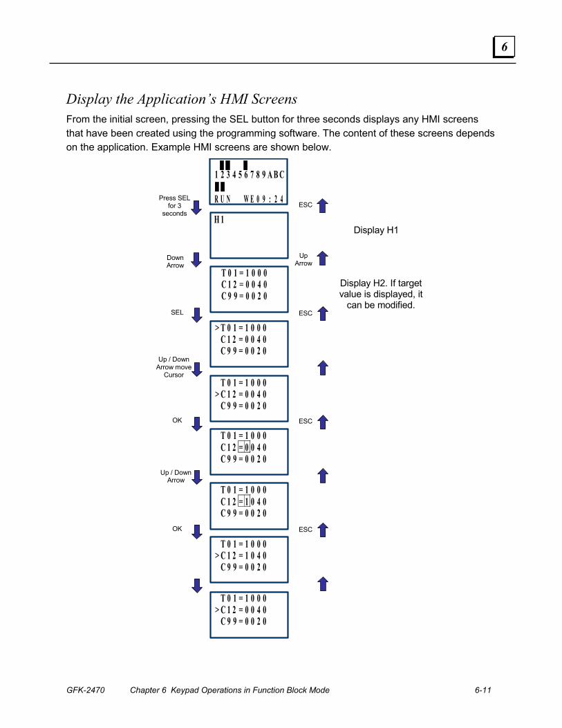
GFK-2470 Chapter 6 Keypad Operations in Function Block Mode 6-11
6
Display the Application’s HMI Screens From the initial screen, pressing the SEL button for three seconds displays any HMI screens that have been created using the programming software. The content of these screens depends on the application. Example HMI screens are shown below.
Press SEL for 3
seconds
1 2 3 4 5 6 7 8 9 A B C
R U N W E 0 9 : 2 4
H 1
Display H1
Display H2. If target value is displayed, it
can be modified. SEL
OK
Up / Down Arrow
OK
ESC
ESC
ESC
ESC
T 0 1 = 1 0 0 0 C 1 2 = 0 0 4 0 C 9 9 = 0 0 2 0
Down Arrow
Up Arrow
> T 0 1 = 1 0 0 0 C 1 2 = 0 0 4 0 C 9 9 = 0 0 2 0 Up / Down
Arrow move Cursor
T 0 1 = 1 0 0 0> C 1 2 = 0 0 4 0 C 9 9 = 0 0 2 0
T 0 1 = 1 0 0 0 C 1 2 = 0 0 4 0 C 9 9 = 0 0 2 0
T 0 1 = 1 0 0 0 C 1 2 = 1 0 4 0 C 9 9 = 0 0 2 0
T 0 1 = 1 0 0 0> C 1 2 = 1 0 4 0 C 9 9 = 0 0 2 0
T 0 1 = 1 0 0 0> C 1 2 = 0 0 4 0 C 9 9 = 0 0 2 0
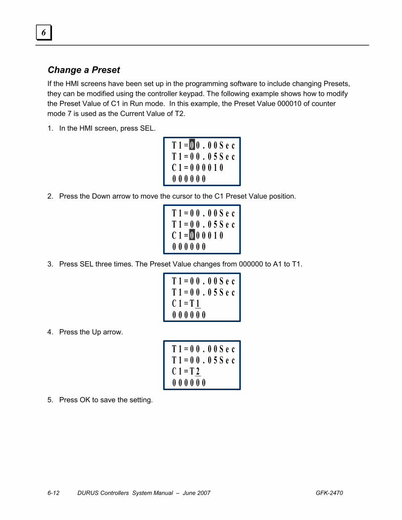
6-12 DURUS Controllers System Manual – June 2007 GFK-2470
6
Change a Preset If the HMI screens have been set up in the programming software to include changing Presets, they can be modified using the controller keypad. The following example shows how to modify the Preset Value of C1 in Run mode. In this example, the Preset Value 000010 of counter mode 7 is used as the Current Value of T2.
1. In the HMI screen, press SEL.
T 1 = 0 0 . 0 0 S e cT 1 = 0 0 . 0 5 S e cC 1 = 0 0 0 0 1 00 0 0 0 0 0
2. Press the Down arrow to move the cursor to the C1 Preset Value position.
T 1 = 0 0 . 0 0 S e cT 1 = 0 0 . 0 5 S e cC 1 = 0 0 0 0 1 00 0 0 0 0 0
3. Press SEL three times. The Preset Value changes from 000000 to A1 to T1.
T 1 = 0 0 . 0 0 S e cT 1 = 0 0 . 0 5 S e cC 1 = T 10 0 0 0 0 0
4. Press the Up arrow.
T 1 = 0 0 . 0 0 S e cT 1 = 0 0 . 0 5 S e cC 1 = T 20 0 0 0 0 0
5. Press OK to save the setting.
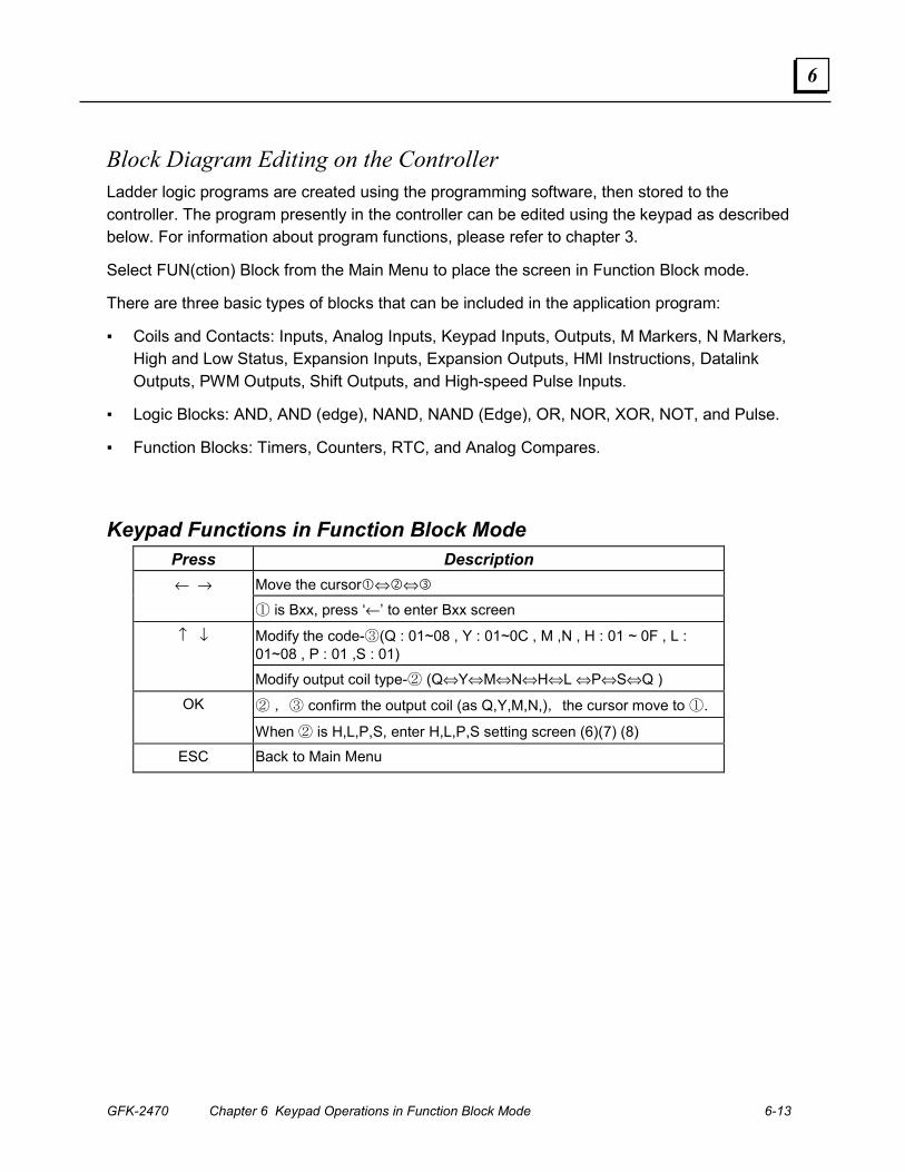
GFK-2470 Chapter 6 Keypad Operations in Function Block Mode 6-13
6
Block Diagram Editing on the Controller Ladder logic programs are created using the programming software, then stored to the controller. The program presently in the controller can be edited using the keypad as described below. For information about program functions, please refer to chapter 3.
Select FUN(ction) Block from the Main Menu to place the screen in Function Block mode.
There are three basic types of blocks that can be included in the application program:
▪ Coils and Contacts: Inputs, Analog Inputs, Keypad Inputs, Outputs, M Markers, N Markers, High and Low Status, Expansion Inputs, Expansion Outputs, HMI Instructions, Datalink Outputs, PWM Outputs, Shift Outputs, and High-speed Pulse Inputs.
▪ Logic Blocks: AND, AND (edge), NAND, NAND (Edge), OR, NOR, XOR, NOT, and Pulse.
▪ Function Blocks: Timers, Counters, RTC, and Analog Compares.
Keypad Functions in Function Block Mode Press Description
Move the cursor�⇔�⇔� ← →
① is Bxx, press ‘←’ to enter Bxx screen
Modify the code-③(Q : 01~08 , Y : 01~0C , M ,N , H : 01 ~ 0F , L : 01~08 , P : 01 ,S : 01)
↑ ↓
Modify output coil type-② (Q⇔Y⇔M⇔N⇔H⇔L ⇔P⇔S⇔Q )
② ,③ confirm the output coil (as Q,Y,M,N,),the cursor move to ①. OK
When ② is H,L,P,S, enter H,L,P,S setting screen (6)(7) (8)
ESC Back to Main Menu
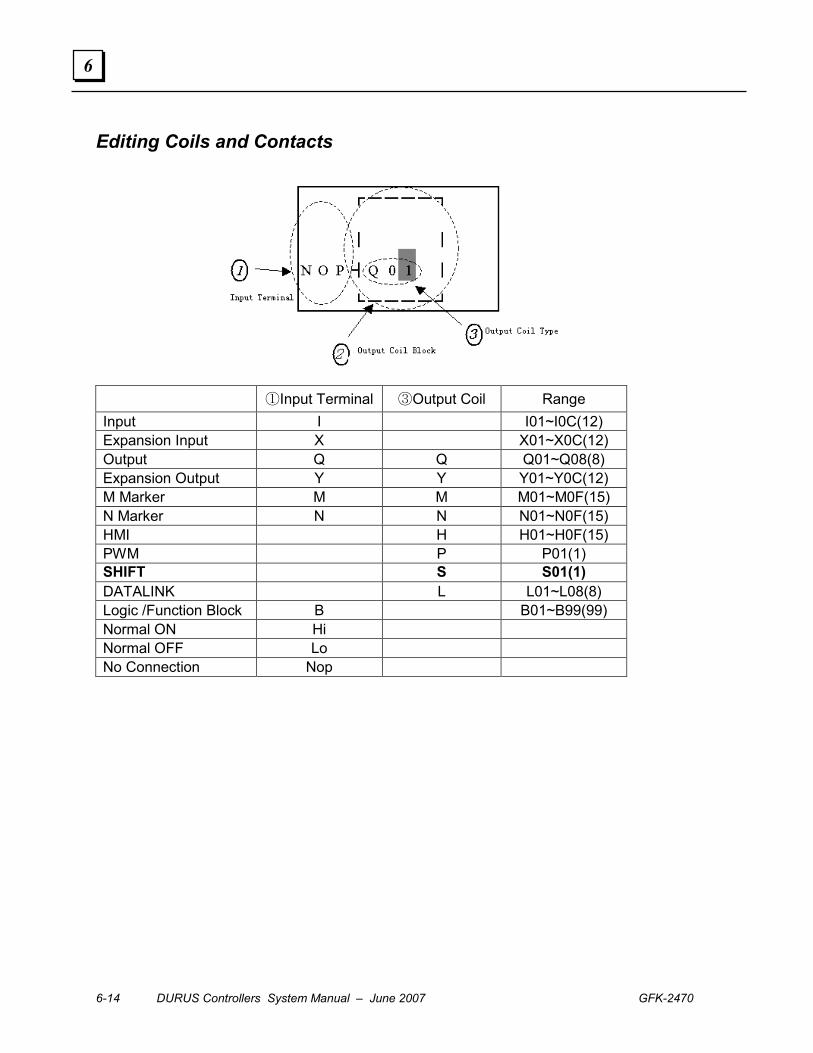
6-14 DURUS Controllers System Manual – June 2007 GFK-2470
6
Editing Coils and Contacts
①Input Terminal ③Output Coil Range Input I I01~I0C(12) Expansion Input X X01~X0C(12) Output Q Q Q01~Q08(8) Expansion Output Y Y Y01~Y0C(12) M Marker M M M01~M0F(15) N Marker N N N01~N0F(15) HMI H H01~H0F(15) PWM P P01(1) SHIFT S S01(1) DATALINK L L01~L08(8) Logic /Function Block B B01~B99(99) Normal ON Hi Normal OFF Lo No Connection Nop
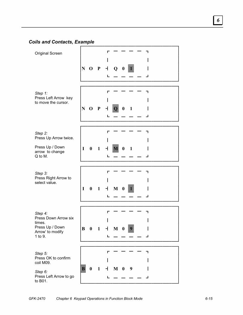
GFK-2470 Chapter 6 Keypad Operations in Function Block Mode 6-15
6
Coils and Contacts, Example
┏ ━ ━ ━ ━ ┓
┃ ┃
N O P ┫ Q 0 1 ┃
Original Screen
┗ ━ ━ ━ ━ ┛
┏ ━ ━ ━ ━ ┓
┃ ┃
N O P ┫ Q 0 1 ┃
Step 1: Press Left Arrow key to move the cursor.
┗ ━ ━ ━ ━ ┛
┏ ━ ━ ━ ━ ┓
┃ ┃
I 0 1 ┫ M 0 1 ┃
Step 2: Press Up Arrow twice. Press Up / Down arrow to change Q to M. ┗ ━ ━ ━ ━ ┛
┏ ━ ━ ━ ━ ┓
┃ ┃
I 0 1 ┫ M 0 1 ┃
Step 3: Press Right Arrow to select value.
┗ ━ ━ ━ ━ ┛
┏ ━ ━ ━ ━ ┓
┃ ┃
B 0 1 ┫ M 0 9 ┃
Step 4: Press Down Arrow six times. Press Up / Down Arrow’ to modify 1 to 9. ┗ ━ ━ ━ ━ ┛
┏ ━ ━ ━ ━ ┓
┃ ┃
B 0 1 ┫ M 0 9 ┃
Step 5: Press OK to confirm coil M09. Step 6: Press Left Arrow to go to B01.
┗ ━ ━ ━ ━ ┛
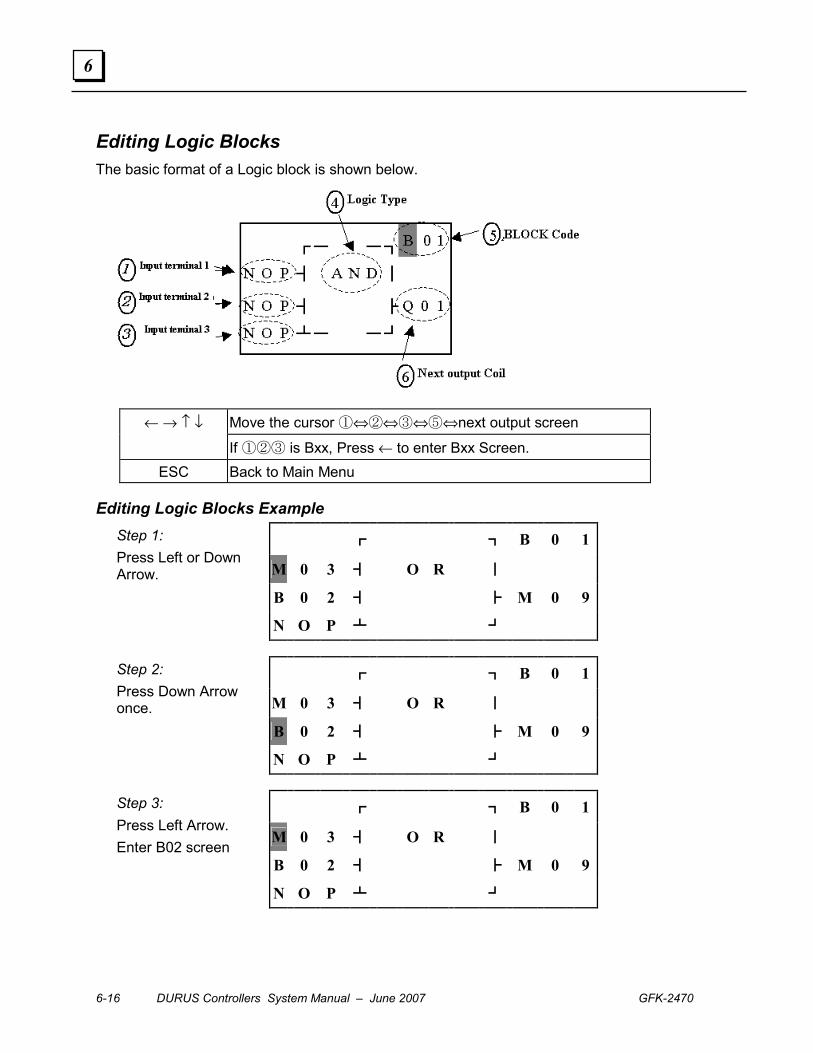
6-16 DURUS Controllers System Manual – June 2007 GFK-2470
6
Editing Logic Blocks The basic format of a Logic block is shown below.
Move the cursor ①⇔②⇔③⇔⑤⇔next output screen ← → ↑ ↓
If ①②③ is Bxx, Press ← to enter Bxx Screen. ESC Back to Main Menu
Editing Logic Blocks Example
┏ ┓ B 0 1
M 0 3 ┫ O R ┃
B 0 2 ┫ ┣ M 0 9
Step 1: Press Left or Down Arrow.
N O P ┻ ┛
┏ ┓ B 0 1
M 0 3 ┫ O R ┃
B 0 2 ┫ ┣ M 0 9
Step 2: Press Down Arrow once.
N O P ┻ ┛
┏ ┓ B 0 1
M 0 3 ┫ O R ┃
B 0 2 ┫ ┣ M 0 9
Step 3: Press Left Arrow. Enter B02 screen
N O P ┻ ┛
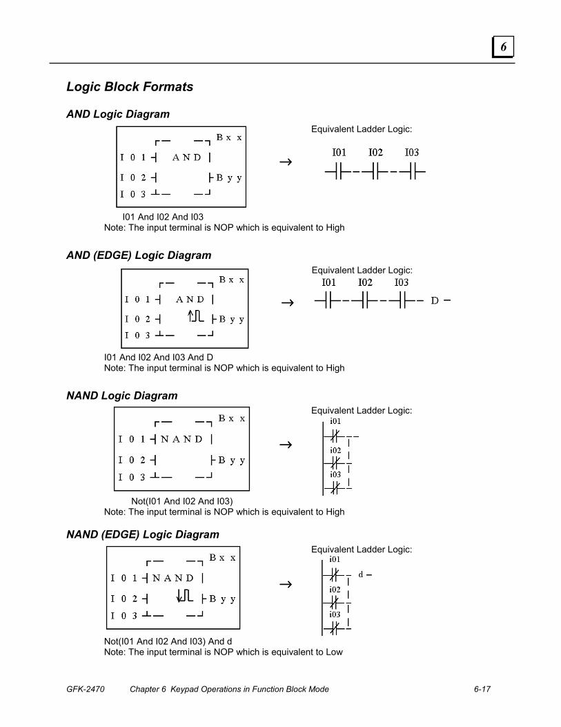
GFK-2470 Chapter 6 Keypad Operations in Function Block Mode 6-17
6
Logic Block Formats
AND Logic Diagram
→→→→
Equivalent Ladder Logic:
I01 And I02 And I03 Note: The input terminal is NOP which is equivalent to High
AND (EDGE) Logic Diagram
→→→→
Equivalent Ladder Logic:
I01 And I02 And I03 And D Note: The input terminal is NOP which is equivalent to High
NAND Logic Diagram
→→→→
Equivalent Ladder Logic:
Not(I01 And I02 And I03)
Note: The input terminal is NOP which is equivalent to High
NAND (EDGE) Logic Diagram
→→→→
Equivalent Ladder Logic:
Not(I01 And I02 And I03) And d Note: The input terminal is NOP which is equivalent to Low
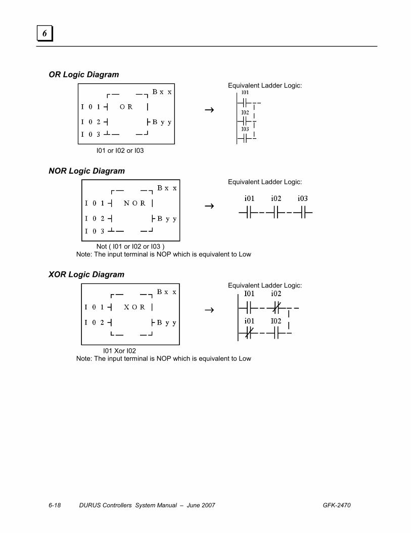
6-18 DURUS Controllers System Manual – June 2007 GFK-2470
6
OR Logic Diagram
→→→→
Equivalent Ladder Logic:
I01 or I02 or I03
NOR Logic Diagram
→→→→
Equivalent Ladder Logic:
Not ( I01 or I02 or I03 ) Note: The input terminal is NOP which is equivalent to Low
XOR Logic Diagram
→→→→
Equivalent Ladder Logic:
I01 Xor I02 Note: The input terminal is NOP which is equivalent to Low
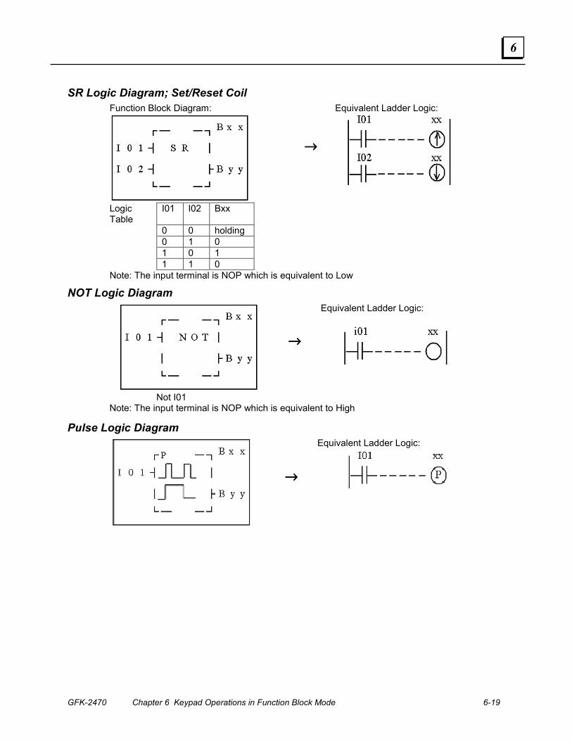
GFK-2470 Chapter 6 Keypad Operations in Function Block Mode 6-19
6
SR Logic Diagram; Set/Reset Coil Function Block Diagram:
→→→→
Equivalent Ladder Logic:
Logic Table
I01 I02 Bxx
0 0 holding 0 1 0 1 0 1 1 1 0 Note: The input terminal is NOP which is equivalent to Low
NOT Logic Diagram
→→→→
Equivalent Ladder Logic:
Not I01 Note: The input terminal is NOP which is equivalent to High
Pulse Logic Diagram
→→→→
Equivalent Ladder Logic:
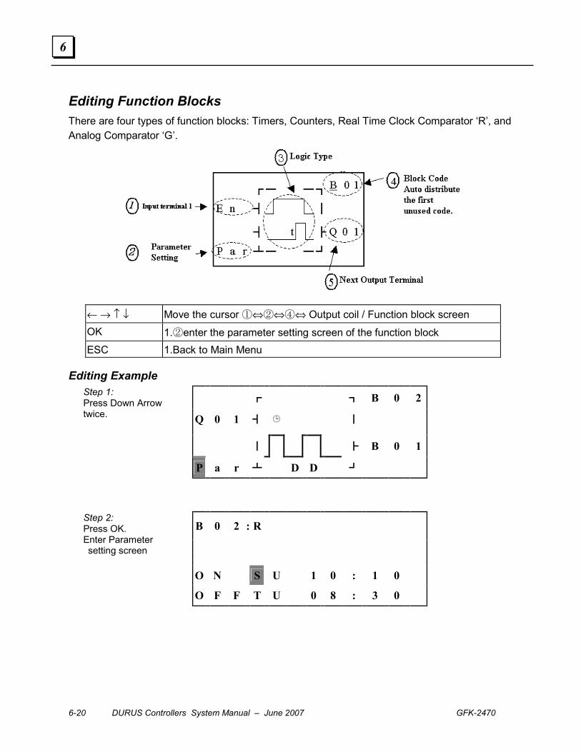
6-20 DURUS Controllers System Manual – June 2007 GFK-2470
6
Editing Function Blocks There are four types of function blocks: Timers, Counters, Real Time Clock Comparator ‘R’, and Analog Comparator ‘G’.
← → ↑ ↓ Move the cursor ①⇔②⇔④⇔ Output coil / Function block screen OK 1.②enter the parameter setting screen of the function block ESC 1.Back to Main Menu
Editing Example
┏ ┓ B 0 2
Q 0 1 ┫ � ┃
┃ ┣ B 0 1
Step 1: Press Down Arrow twice.
P a r ┻ D D ┛
B 0 2 : R
O N S U 1 0 : 1 0
Step 2: Press OK. Enter Parameter setting screen
O F F T U 0 8 : 3 0
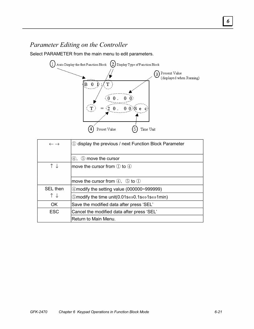
GFK-2470 Chapter 6 Keypad Operations in Function Block Mode 6-21
6
Parameter Editing on the Controller Select PARAMETER from the main menu to edit parameters.
① display the previous / next Function Block Parameter
← →
④,⑤ move the cursor
move the cursor from ① to ④
↑ ↓
move the cursor from ④,⑤ to ①
④modify the setting value (000000~999999) SEL then ↑ ↓ ⑤modify the time unit(0.01s⇔0.1s⇔1s⇔1min) OK Save the modified data after press ‘SEL’
Cancel the modified data after press ‘SEL’ ESC Return to Main Menu.
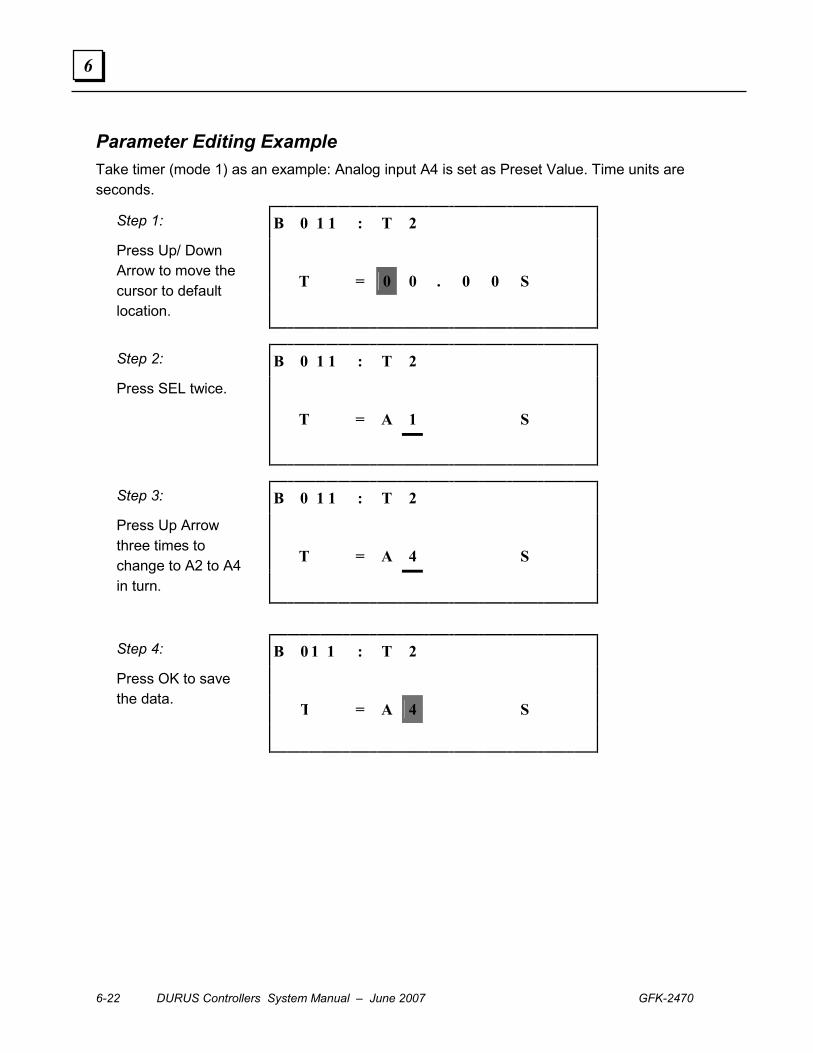
6-22 DURUS Controllers System Manual – June 2007 GFK-2470
6
Parameter Editing Example Take timer (mode 1) as an example: Analog input A4 is set as Preset Value. Time units are seconds.
B 0 1 1 : T 2
T = 0 0 . 0 0 S
Step 1:
Press Up/ Down Arrow to move the cursor to default location.
B 0 1 1 : T 2
T = A 1 S
Step 2:
Press SEL twice.
B 0 1 1 : T 2
T = A 4 S
Step 3:
Press Up Arrow three times to change to A2 to A4 in turn.
B 0 1 1 : T 2
T = A 4 S
Step 4:
Press OK to save the data.
GFK-2470 7-1
Software Operation in Block Diagram Mode
The programming software has two separate programming modes: Ladder Logic and
Function Block Diagram. After the Ladder Logic or Function Block Diagram mode is
selected on the software startup screen, all software operations continue in that mode.
This chapter explains how use the programming software for programming, simulation,
and emulation in Function Block Diagram mode. Similar instructions for using Ladder
Logic mode are in chapter 5.
▪ Using the Block Diagram Programming Software
▪ File Menu Functions
▪ Edit Menu Functions
▪ Operation Menu Functions
▪ View Menu Functions
▪ Using Simulation Mode
▪ Using Monitor Mode
▪ Programming in Block Diagram Mode
▪ Program Editing
▪ Program Elements
▪ Programming Steps
Chapter
7
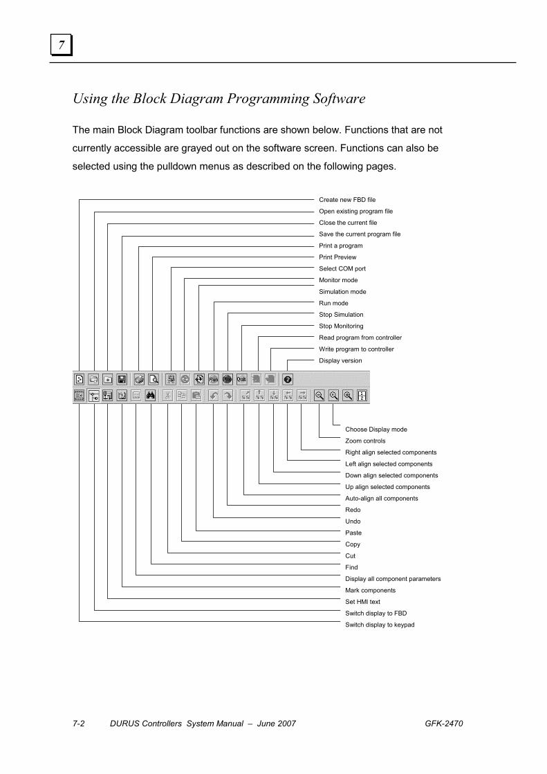
7-2 DURUS Controllers System Manual – June 2007 GFK-2470
7
Using the Block Diagram Programming Software
The main Block Diagram toolbar functions are shown below. Functions that are not
currently accessible are grayed out on the software screen. Functions can also be
selected using the pulldown menus as described on the following pages.
Create new FBD file
Open existing program file
Close the current file
Save the current program file
Print a program
Print Preview
Select COM port
Monitor mode
Simulation mode
Run mode
Stop Simulation
Stop Monitoring
Read program from controller
Write program to controller
Display version
Choose Display mode
Zoom controls
Right align selected components
Left align selected components
Down align selected components
Up align selected components
Auto-align all components
Redo
Undo
Paste
Copy
Cut
Find
Display all component parameters
Mark components
Set HMI text
Switch display to FBD
Switch display to keypad

GFK-2470 Chapter 7 Software Operation in Block Diagram Mode 7-3
7
File Menu Functions Select File or use the appropriate buttons to access the file functions:
New Create a new file. Select a controller model in the dialog box to create a
new FBD program.
Open Select an existing program file to open.
Close Close a program file. A file cannot be closed during Emulation mode or
Supervising mode.
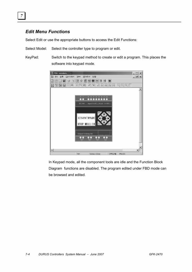
7-4 DURUS Controllers System Manual – June 2007 GFK-2470
7
Edit Menu Functions Select Edit or use the appropriate buttons to access the Edit Functions:
Select Model: Select the controller type to program or edit.
KeyPad: Switch to the keypad method to create or edit a program. This places the
software into keypad mode.
In Keypad mode, all the component tools are idle and the Function Block
Diagram functions are disabled. The program edited under FBD mode can
be browsed and edited.
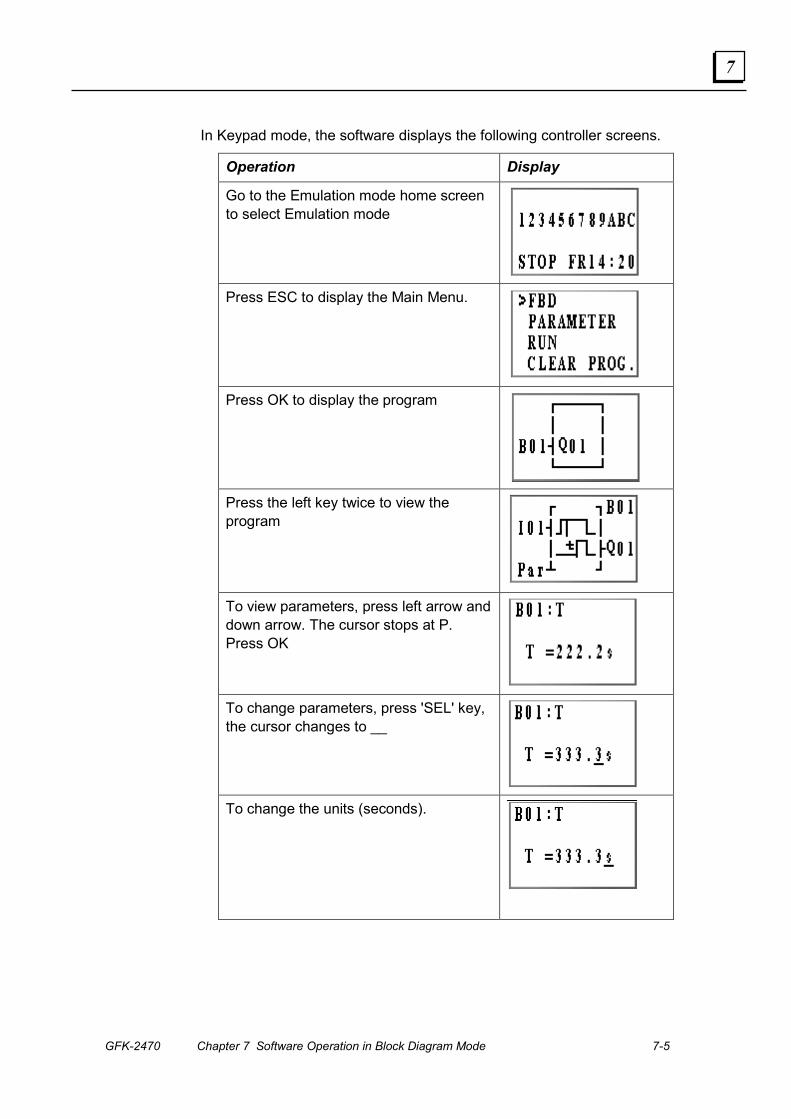
GFK-2470 Chapter 7 Software Operation in Block Diagram Mode 7-5
7
In Keypad mode, the software displays the following controller screens.
Operation Display
Go to the Emulation mode home screen to select Emulation mode
Press ESC to display the Main Menu.
Press OK to display the program
Press the left key twice to view the program
To view parameters, press left arrow and down arrow. The cursor stops at P. Press OK
To change parameters, press 'SEL' key, the cursor changes to __
To change the units (seconds).
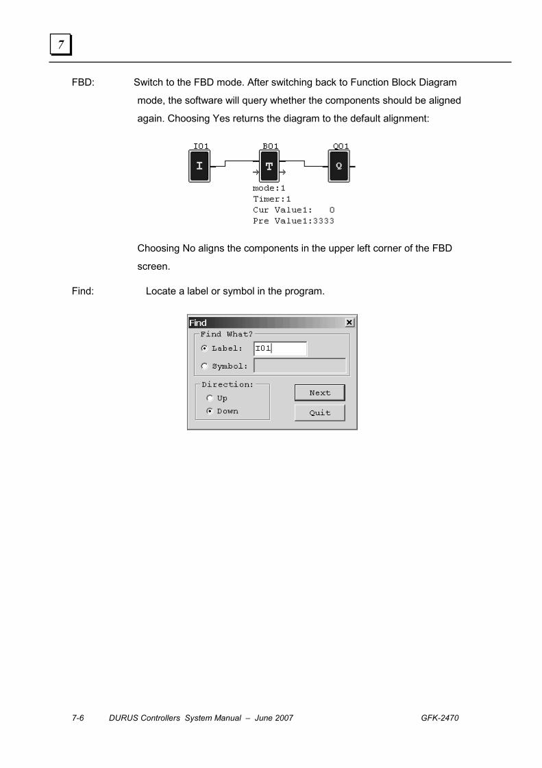
7-6 DURUS Controllers System Manual – June 2007 GFK-2470
7
FBD: Switch to the FBD mode. After switching back to Function Block Diagram
mode, the software will query whether the components should be aligned
again. Choosing Yes returns the diagram to the default alignment:
Choosing No aligns the components in the upper left corner of the FBD
screen.
Find: Locate a label or symbol in the program.
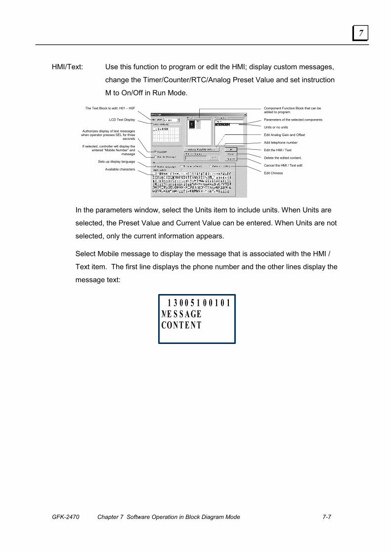
GFK-2470 Chapter 7 Software Operation in Block Diagram Mode 7-7
7
HMI/Text: Use this function to program or edit the HMI; display custom messages,
change the Timer/Counter/RTC/Analog Preset Value and set instruction
M to On/Off in Run Mode.
Component Function Block that can be added to program Parameters of the selected components Units or no units Edit Analog Gain and Offset Add telephone number Edit the HMI / Text Delete the edited content. Cancel the HMI / Text edit Edit Chinese
The Text Block to edit: H01 – H0F
LCD Text Display
Authorizes display of text messageswhen operator presses SEL for three
seconds
If selected, controller will display theentered “Mobile Number” and
message
Sets up display language
Available characters
In the parameters window, select the Units item to include units. When Units are
selected, the Preset Value and Current Value can be entered. When Units are not
selected, only the current information appears.
Select Mobile message to display the message that is associated with the HMI /
Text item. The first line displays the phone number and the other lines display the
message text:
1 3 0 0 5 1 0 0 1 0 1ME S S A GECO N T E N T
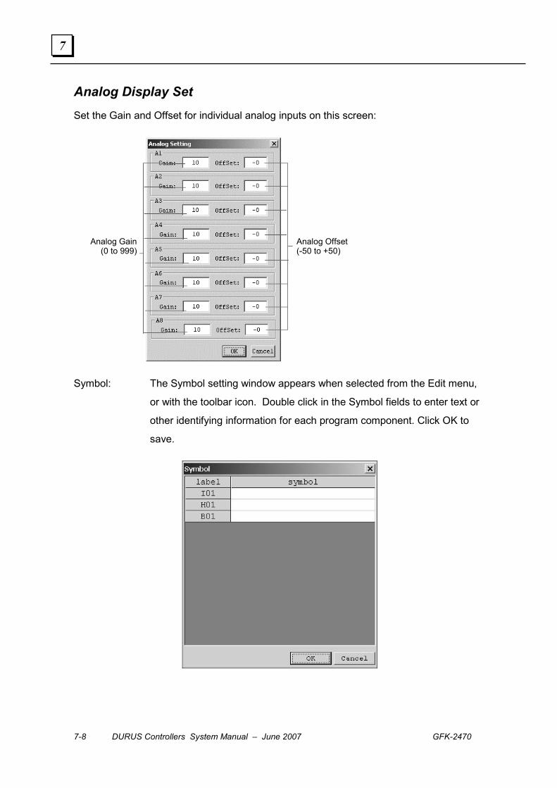
7-8 DURUS Controllers System Manual – June 2007 GFK-2470
7
Analog Display Set Set the Gain and Offset for individual analog inputs on this screen:
Analog Gain (0 to 999)
Analog Offset (-50 to +50)
Symbol: The Symbol setting window appears when selected from the Edit menu,
or with the toolbar icon. Double click in the Symbol fields to enter text or
other identifying information for each program component. Click OK to
save.

GFK-2470 Chapter 7 Software Operation in Block Diagram Mode 7-9
7
Parameters List: To display and modify all the parameters of the components under FBD
mode. Double click the component in the list to modify the parameters.
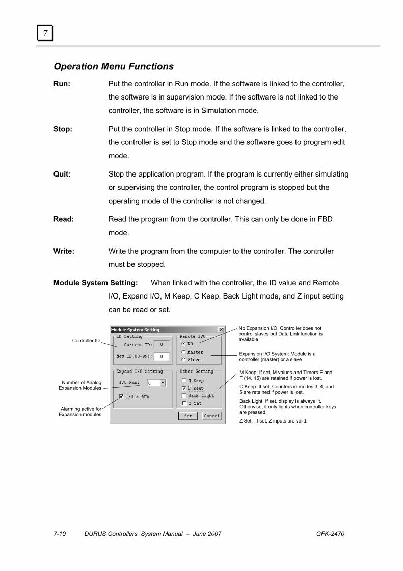
7-10 DURUS Controllers System Manual – June 2007 GFK-2470
7
Operation Menu Functions Run: Put the controller in Run mode. If the software is linked to the controller,
the software is in supervision mode. If the software is not linked to the
controller, the software is in Simulation mode.
Stop: Put the controller in Stop mode. If the software is linked to the controller,
the controller is set to Stop mode and the software goes to program edit
mode.
Quit: Stop the application program. If the program is currently either simulating
or supervising the controller, the control program is stopped but the
operating mode of the controller is not changed.
Read: Read the program from the controller. This can only be done in FBD
mode.
Write: Write the program from the computer to the controller. The controller
must be stopped.
Module System Setting: When linked with the controller, the ID value and Remote
I/O, Expand I/O, M Keep, C Keep, Back Light mode, and Z input setting
can be read or set.
Controller ID
Number of Analog Expansion Modules
Alarming active for Expansion modules
No Expansion I/O: Controller does not control slaves but Data Link function is available
Expansion I/O System: Module is a controller (master) or a slave
M Keep: If set, M values and Timers E and F (14, 15) are retained if power is lost.
C Keep: If set, Counters in modes 3, 4, and 5 are retained if power is lost.
Back Light: If set, display is always lit. Otherwise, it only lights when controller keysare pressed.
Z Set: If set, Z inputs are valid.

GFK-2470 Chapter 7 Software Operation in Block Diagram Mode 7-11
7
RTC Set: When linked with the controller, the Real-time Clock value can be set. If
not linked with the controller, the computer will display its own clock
value.
Day of the Week Hour (0 to 23) Minute (0 to 59) Year (0 to 99) Month (1 to 12) Day of the Month (1 to 31)
Password: In Password mode, the correct password is required to enter program edit
mode, or to use the ESC button to exit the Home page in Run Mode.
When the software is linked with the controller, the password can be set
or changed. The numbers 0000 and FFFF both select No Password
mode. Any other number from A000 to FFFE becomes the password. If
the password is forgotten, the only way to recover is using Clear
Program, which also clears the password.
Set Password
Change Password
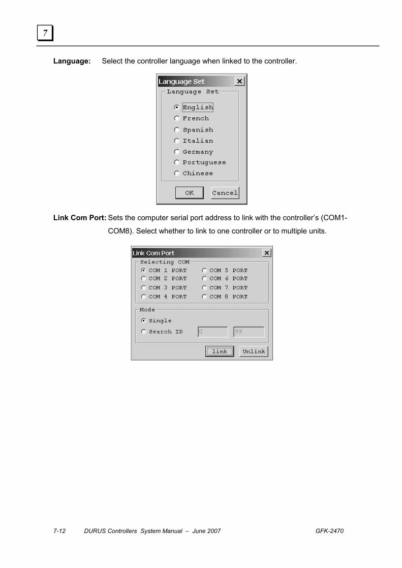
7-12 DURUS Controllers System Manual – June 2007 GFK-2470
7
Language: Select the controller language when linked to the controller.
Link Com Port: Sets the computer serial port address to link with the controller’s (COM1-
COM8). Select whether to link to one controller or to multiple units.

GFK-2470 Chapter 7 Software Operation in Block Diagram Mode 7-13
7
View Menu Functions Input Status Tool: Display/hide the input and output state tool. The tool is only
available in the FBD edit window.
Data Link Status Tool: Display/hide Data Link state tool. The tool is only available in the
window containing 'Data Link' Function.
High Speed Input Tool: Display/hide High Speed Input Tool in the Keypad Edit window.
Can be used by the controller in Simulation Mode to simulate the High
Speed 1K Hz Input I1 and I2 for Counter function type 7 and 8. When
Input I1/I2 status Off to On, the current count value is added to the I1/I2
Input Value.
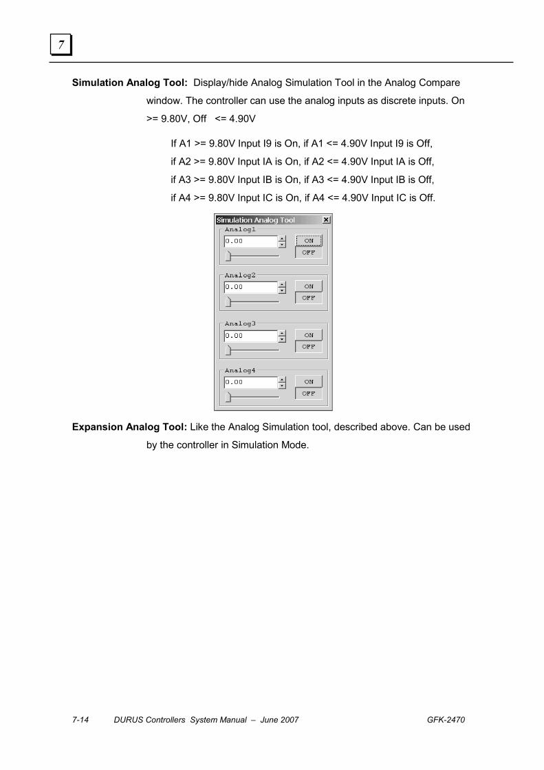
7-14 DURUS Controllers System Manual – June 2007 GFK-2470
7
Simulation Analog Tool: Display/hide Analog Simulation Tool in the Analog Compare
window. The controller can use the analog inputs as discrete inputs. On
>= 9.80V, Off <= 4.90V
If A1 >= 9.80V Input I9 is On, if A1 <= 4.90V Input I9 is Off,
if A2 >= 9.80V Input IA is On, if A2 <= 4.90V Input IA is Off,
if A3 >= 9.80V Input IB is On, if A3 <= 4.90V Input IB is Off,
if A4 >= 9.80V Input IC is On, if A4 <= 4.90V Input IC is Off.
Expansion Analog Tool: Like the Analog Simulation tool, described above. Can be used
by the controller in Simulation Mode.
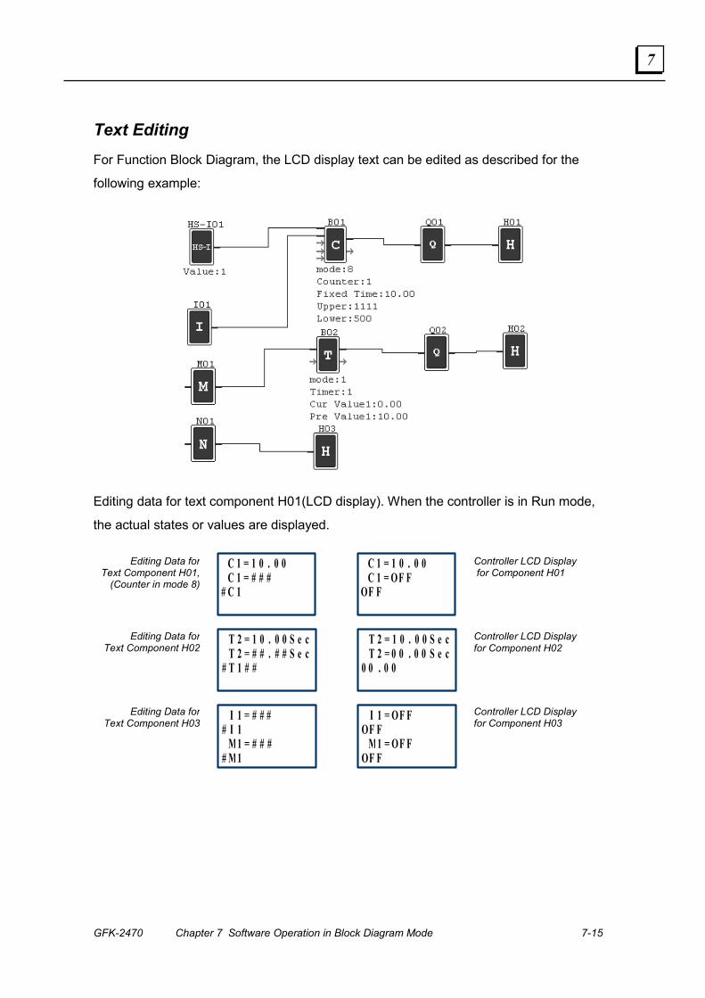
GFK-2470 Chapter 7 Software Operation in Block Diagram Mode 7-15
7
Text Editing For Function Block Diagram, the LCD display text can be edited as described for the
following example:
Editing data for text component H01(LCD display). When the controller is in Run mode,
the actual states or values are displayed.
T 2 = 1 0 . 0 0 S e c T 2 = # # . # # S e c
# T 1 # #
C 1 = 1 0 . 0 0 C 1 = # # #
# C 1
Editing Data for Text Component H01,
(Counter in mode 8)
I 1 = # # # # I 1 M1 = # # #
# M1
Editing Data for Text Component H02
Editing Data for Text Component H03
T 2 = 1 0 . 0 0 S e cT 2 = 0 0 . 0 0 S e c
0 0 . 0 0
C 1 = 1 0 . 0 0C 1 = OF F
OF F
Controller LCD Display for Component H01
I 1 = OF FOF F
M1 = OF FOF F
Controller LCD Display for Component H02
Controller LCD Display for Component H03
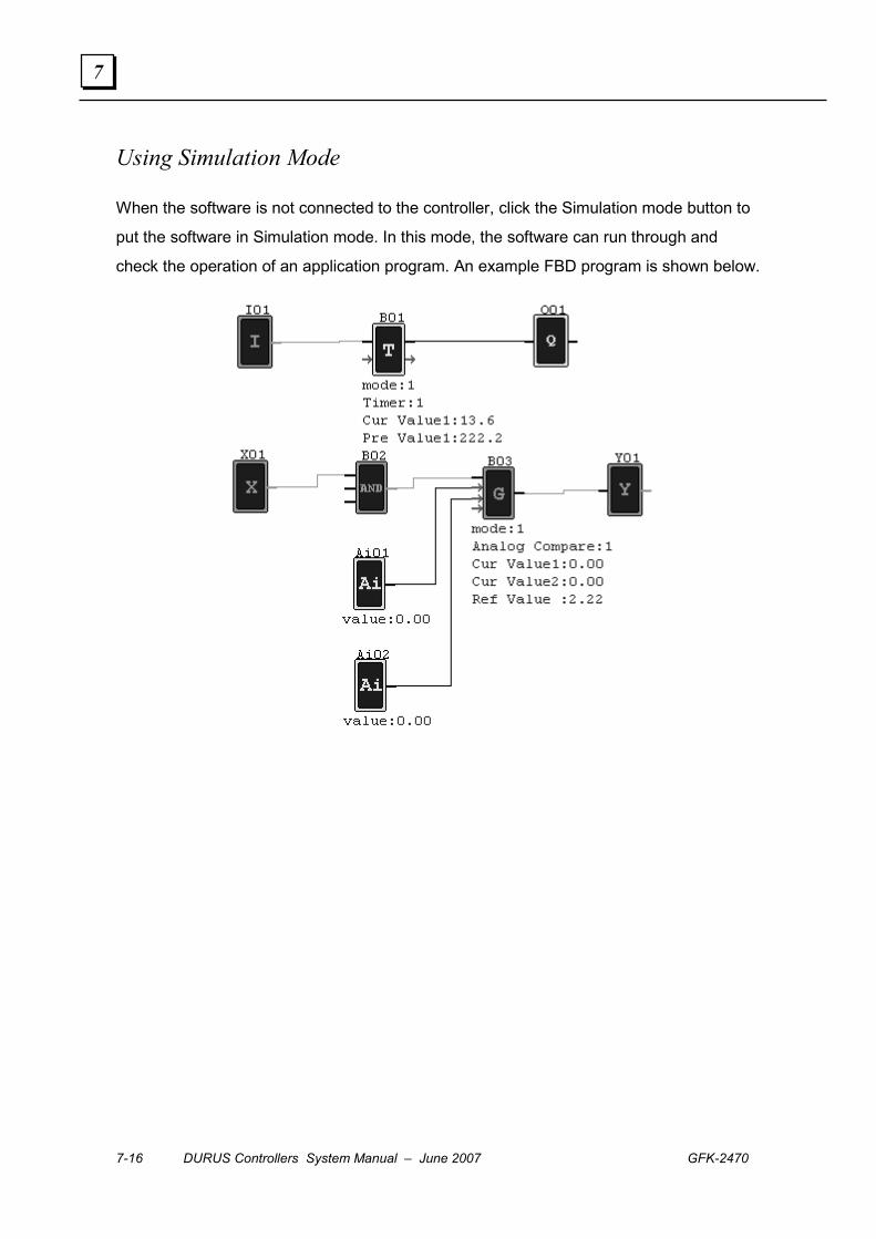
7-16 DURUS Controllers System Manual – June 2007 GFK-2470
7
Using Simulation Mode
When the software is not connected to the controller, click the Simulation mode button to
put the software in Simulation mode. In this mode, the software can run through and
check the operation of an application program. An example FBD program is shown below.
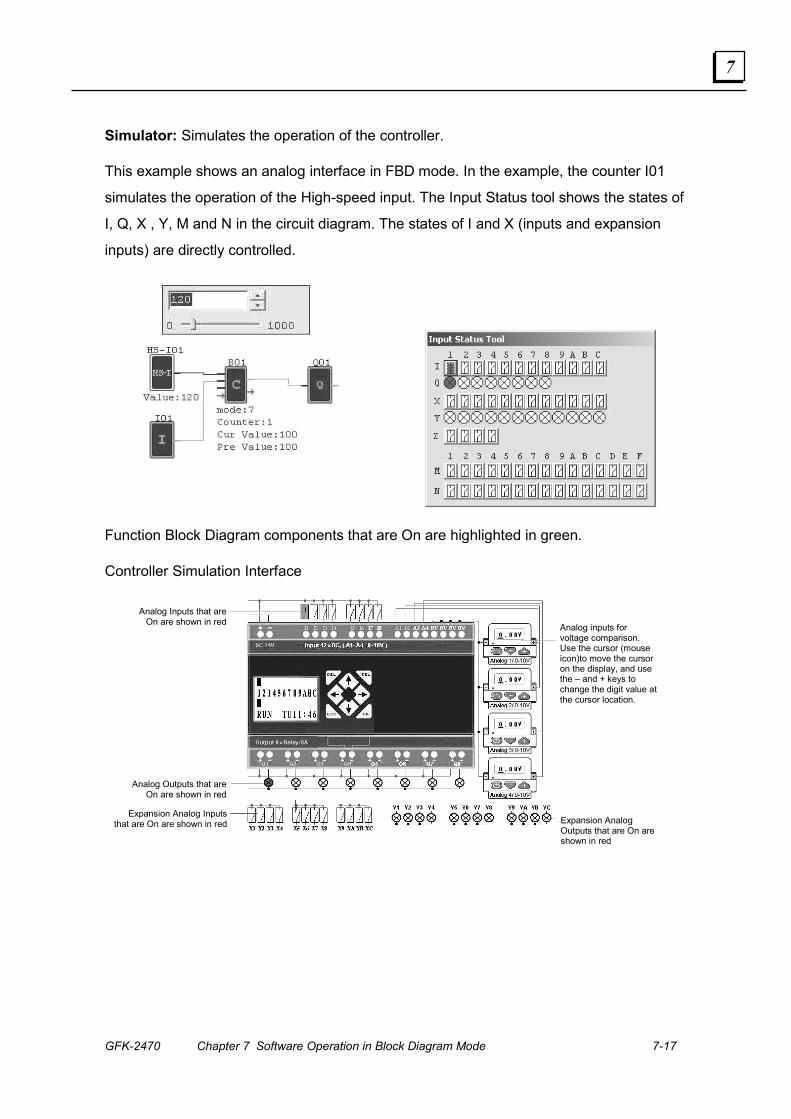
GFK-2470 Chapter 7 Software Operation in Block Diagram Mode 7-17
7
Simulator: Simulates the operation of the controller.
This example shows an analog interface in FBD mode. In the example, the counter I01
simulates the operation of the High-speed input. The Input Status tool shows the states of
I, Q, X , Y, M and N in the circuit diagram. The states of I and X (inputs and expansion
inputs) are directly controlled.
Function Block Diagram components that are On are highlighted in green.
Controller Simulation Interface
Analog Inputs that are
On are shown in red
Analog Outputs that are On are shown in red
Expansion Analog Inputs that are On are shown in red Expansion Analog
Outputs that are On are shown in red
Analog inputs for voltage comparison. Use the cursor (mouse icon)to move the cursor on the display, and use the – and + keys to change the digit value at the cursor location.
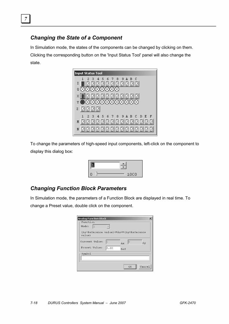
7-18 DURUS Controllers System Manual – June 2007 GFK-2470
7
Changing the State of a Component In Simulation mode, the states of the components can be changed by clicking on them.
Clicking the corresponding button on the 'Input Status Tool' panel will also change the
state.
To change the parameters of high-speed input components, left-click on the component to
display this dialog box:
Changing Function Block Parameters In Simulation mode, the parameters of a Function Block are displayed in real time. To
change a Preset value, double click on the component.

GFK-2470 Chapter 7 Software Operation in Block Diagram Mode 7-19
7
Simulating a Data Link Function If the program has Data Link component, its function can be simulated on the Data Link
tool panel. The program cannot be edited during Simulation mode; press ESC or click on
the Stop button.
When you switch the mode to Keypad interface, the FBD program is available under
Keypad. The Simulation screen is shown below:
On this screen you can:
(1) Click Inputs to change their status.
(2) Click External Inputs to change their status.
(3) Display External Output states
(4) Display Output states.
(5) Click the buttons on the analog modules to change analog values.
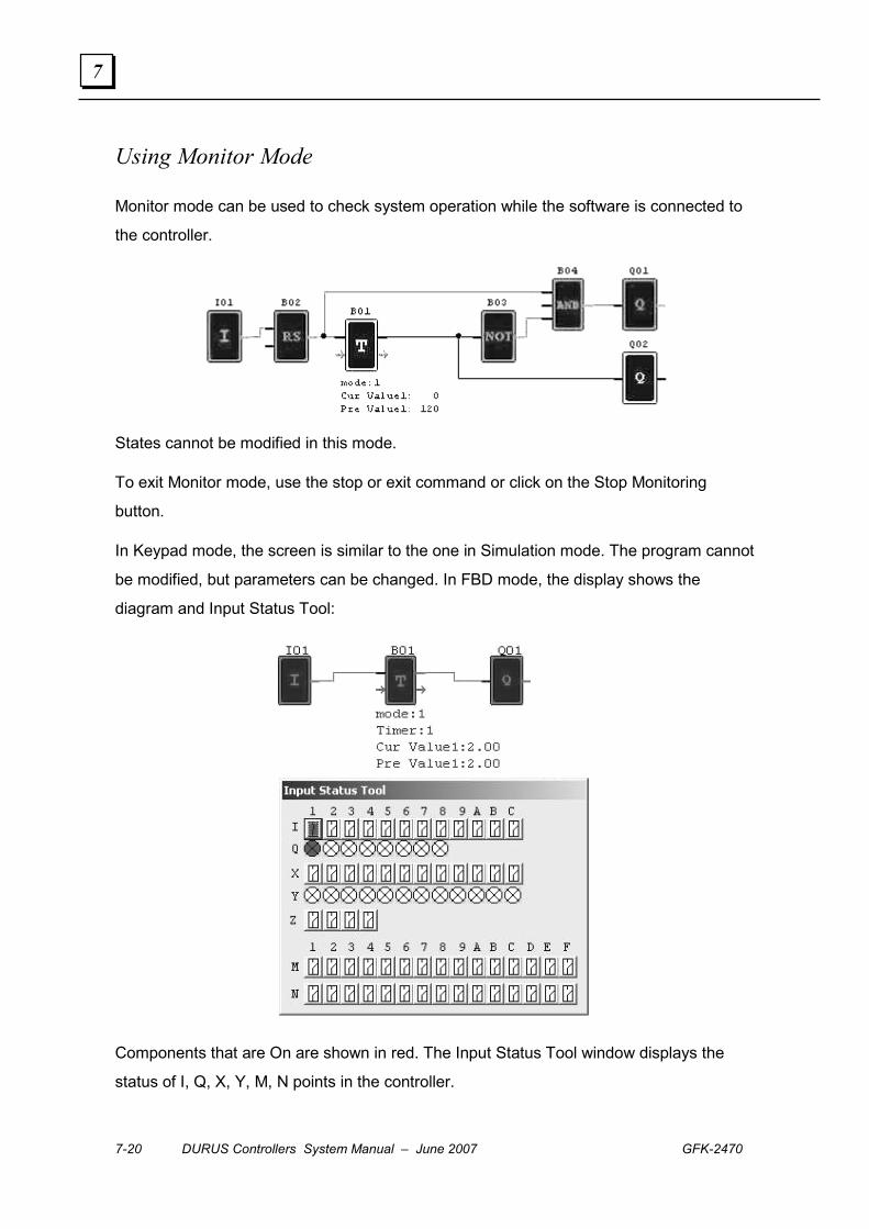
7-20 DURUS Controllers System Manual – June 2007 GFK-2470
7
Using Monitor Mode
Monitor mode can be used to check system operation while the software is connected to
the controller.
States cannot be modified in this mode.
To exit Monitor mode, use the stop or exit command or click on the Stop Monitoring
button.
In Keypad mode, the screen is similar to the one in Simulation mode. The program cannot
be modified, but parameters can be changed. In FBD mode, the display shows the
diagram and Input Status Tool:
Components that are On are shown in red. The Input Status Tool window displays the
status of I, Q, X, Y, M, N points in the controller.
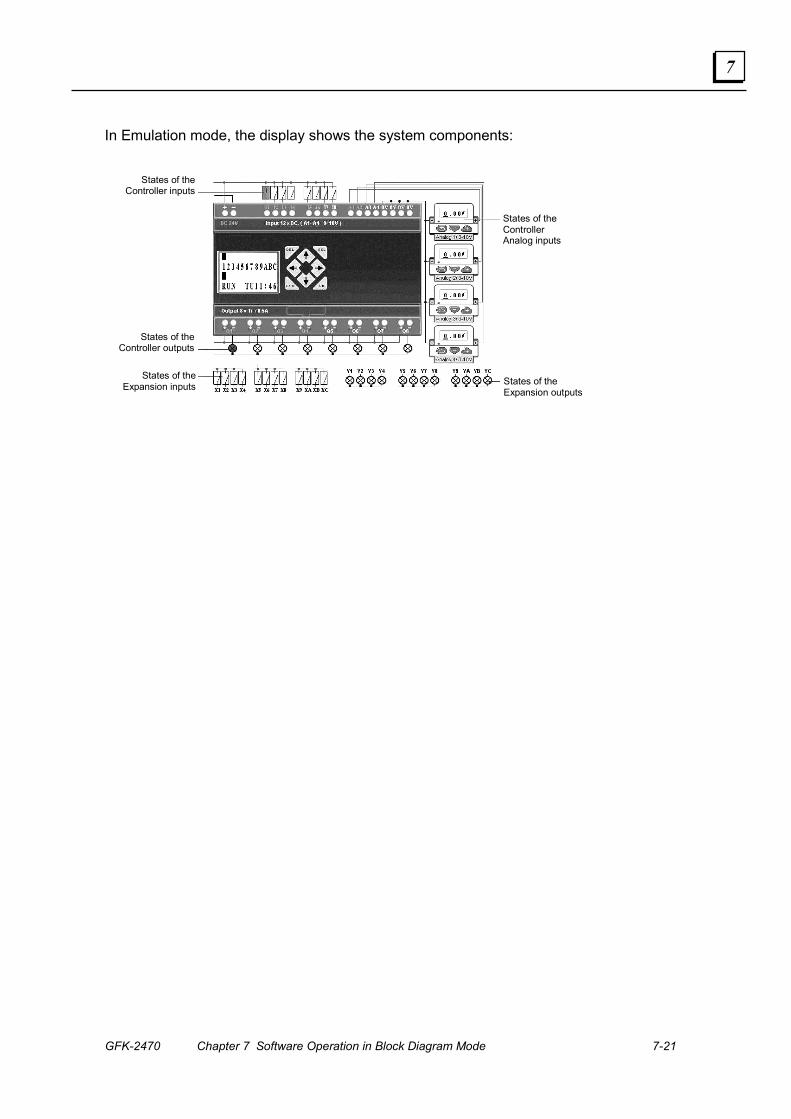
GFK-2470 Chapter 7 Software Operation in Block Diagram Mode 7-21
7
In Emulation mode, the display shows the system components:
States of the Controller inputs
States of the Controller outputs
States of the Expansion inputs States of the
Expansion outputs
States of the Controller Analog inputs
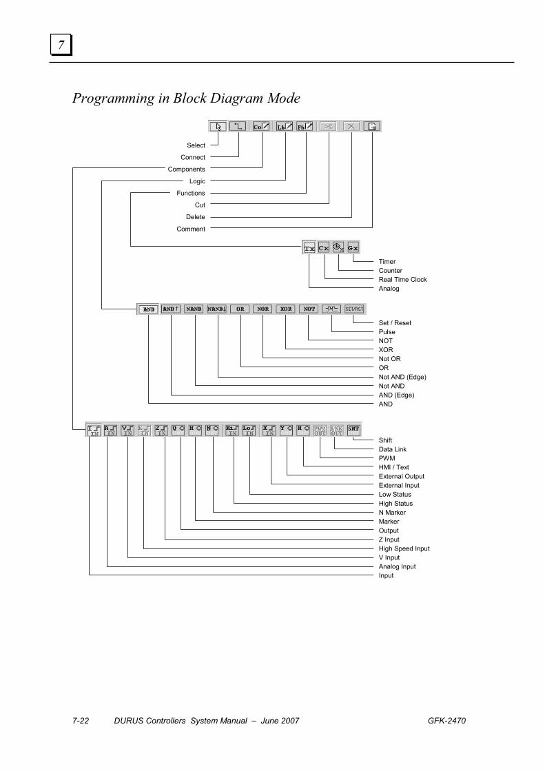
7-22 DURUS Controllers System Manual – June 2007 GFK-2470
7
Programming in Block Diagram Mode
Select
Connect
Components
Logic
Functions
Cut
Delete
Comment
Timer Counter Real Time Clock Analog
Set / Reset Pulse NOT XOR Not OR OR Not AND (Edge) Not AND AND (Edge) AND
Shift Data Link PWM HMI / Text External Output External Input Low Status High Status N Marker Marker Output Z Input High Speed Input V Input Analog Input Input
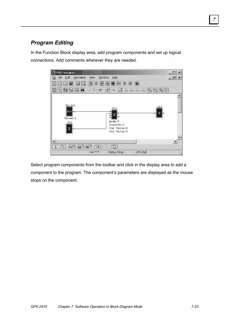
GFK-2470 Chapter 7 Software Operation in Block Diagram Mode 7-23
7
Program Editing In the Function Block display area, add program components and set up logical
connections. Add comments wherever they are needed.
Select program components from the toolbar and click in the display area to add a
component to the program. The component’s parameters are displayed as the mouse
stops on the component.

7-24 DURUS Controllers System Manual – June 2007 GFK-2470
7
Program Elements (1) Function Name
(2) Connector
(3) Parameters
(4) Input
(5) Output
(6) Number
(7) Parameter Output
(8) Parameter Input
▪ For all models, the maximum number of logic blocks and function blocks is 99. Blocks
are numbered as they are added to the program.
▪ Timer mode 7 uses two timers.
▪ The maximum number of Counters in mode 7 and mode 8 that can be used in a
program is two (two mode 7 counters, or two mode 8 counters, or one of each).
▪ The input pin cannot be connected with the output of the same component.
▪ Any input pin only can be connected to an input state.
▪ The output pins can connect with more than one input pin except in the case of high
speed input components.
▪ The output pin on a high speed component can only connect with high speed input
pins on counter mode 7 and 8. Once connected, the output cannot be connected with
the other input pins.
▪ Blocks cannot be linked in a closed loop.
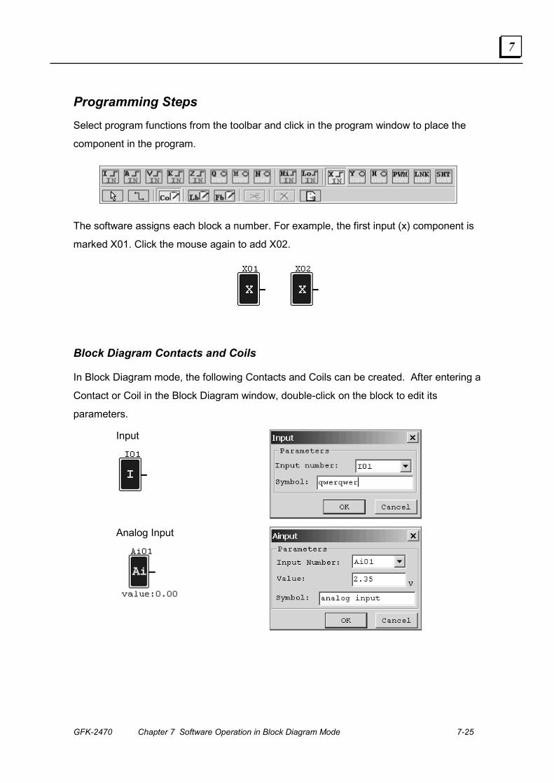
GFK-2470 Chapter 7 Software Operation in Block Diagram Mode 7-25
7
Programming Steps Select program functions from the toolbar and click in the program window to place the
component in the program.
The software assigns each block a number. For example, the first input (x) component is
marked X01. Click the mouse again to add X02.
Block Diagram Contacts and Coils
In Block Diagram mode, the following Contacts and Coils can be created. After entering a
Contact or Coil in the Block Diagram window, double-click on the block to edit its
parameters.
Input
Analog Input

7-26 DURUS Controllers System Manual – June 2007 GFK-2470
7
V Input: Analog input with a value equal to (analog input x gain) = offset
Keypad Input
Output
Marker: Auxiliary Marker
N Marker
High Status
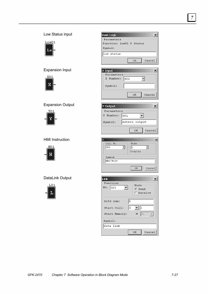
GFK-2470 Chapter 7 Software Operation in Block Diagram Mode 7-27
7
Low Status input
Expansion Input
Expansion Output
HMI Instruction
DataLink Output

7-28 DURUS Controllers System Manual – June 2007 GFK-2470
7
PWM Output
Shift Output
High Speed Input: high speed pulse input
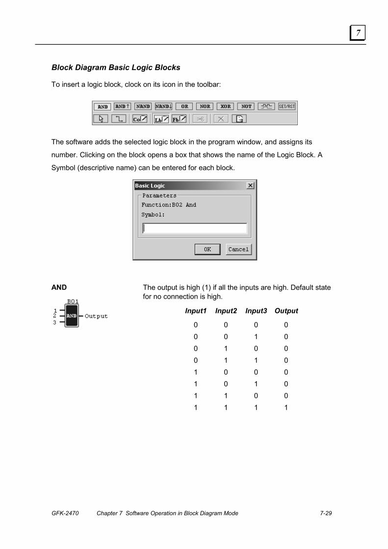
GFK-2470 Chapter 7 Software Operation in Block Diagram Mode 7-29
7
Block Diagram Basic Logic Blocks
To insert a logic block, clock on its icon in the toolbar:
The software adds the selected logic block in the program window, and assigns its
number. Clicking on the block opens a box that shows the name of the Logic Block. A
Symbol (descriptive name) can be entered for each block.
AND
The output is high (1) if all the inputs are high. Default state for no connection is high.
Input1 Input2 Input3 Output
0 0 0 0 0 0 1 0 0 1 0 0 0 1 1 0 1 0 0 0 1 0 1 0 1 1 0 0 1 1 1 1

7-30 DURUS Controllers System Manual – June 2007 GFK-2470
7
AND (Edge)
The output will be high for a period when the present inputs are all 1s and there was at least a '0' input in former period. Then it will be reset to zero. The low will be kept for at least one period before the next high. Default state for no connection is high(1).
NAND
The output is high if at least one input is low. The output is low if all the inputs are high. Default state for no connection is high (1).
Input1 Input2 Input3 Output 0 0 0 1 0 0 1 1 0 1 0 1 0 1 1 1 1 0 0 1 1 0 1 1 1 1 0 1 1 1 1 0
NAND (Edge)
The output is high when there is at least a '0' input in current period and there were all '1' inputs in the previous period. It is then reset to zero. The low is kept for at least one period before the next high. Default state for no connection is high (1).
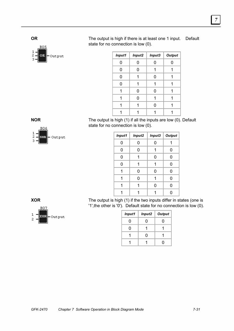
GFK-2470 Chapter 7 Software Operation in Block Diagram Mode 7-31
7
OR
The output is high if there is at least one 1 input. Default state for no connection is low (0).
Input1 Input2 Input3 Output
0 0 0 0 0 0 1 1 0 1 0 1 0 1 1 1 1 0 0 1 1 0 1 1 1 1 0 1 1 1 1 1
NOR
The output is high (1) if all the inputs are low (0). Default state for no connection is low (0).
Input1 Input2 Input3 Output
0 0 0 1 0 0 1 0 0 1 0 0 0 1 1 0 1 0 0 0 1 0 1 0 1 1 0 0 1 1 1 0
XOR
The output is high (1) if the two inputs differ in states (one is '1',the other is '0'). Default state for no connection is low (0).
Input1 Input2 Output
0 0 0 0 1 1 1 0 1 1 1 0
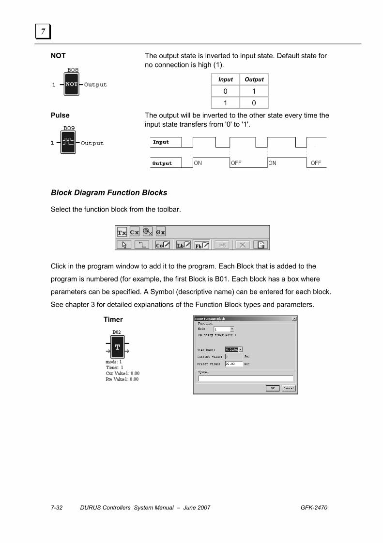
7-32 DURUS Controllers System Manual – June 2007 GFK-2470
7
NOT
The output state is inverted to input state. Default state for no connection is high (1).
Input Output
0 1 1 0
Pulse
The output will be inverted to the other state every time the input state transfers from '0' to '1'.
Block Diagram Function Blocks
Select the function block from the toolbar.
Click in the program window to add it to the program. Each Block that is added to the
program is numbered (for example, the first Block is B01. Each block has a box where
parameters can be specified. A Symbol (descriptive name) can be entered for each block.
See chapter 3 for detailed explanations of the Function Block types and parameters.
Timer

GFK-2470 Chapter 7 Software Operation in Block Diagram Mode 7-33
7
Counter
Real-time Clock
Analog Compare
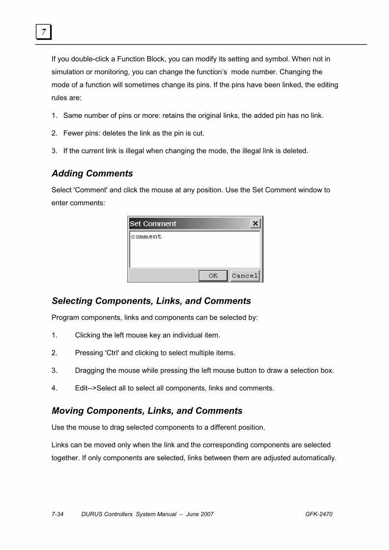
7-34 DURUS Controllers System Manual – June 2007 GFK-2470
7
If you double-click a Function Block, you can modify its setting and symbol. When not in
simulation or monitoring, you can change the function’s mode number. Changing the
mode of a function will sometimes change its pins. If the pins have been linked, the editing
rules are:
1. Same number of pins or more: retains the original links, the added pin has no link.
2. Fewer pins: deletes the link as the pin is cut.
3. If the current link is illegal when changing the mode, the illegal link is deleted.
Adding Comments Select 'Comment' and click the mouse at any position. Use the Set Comment window to
enter comments:
Selecting Components, Links, and Comments Program components, links and components can be selected by:
1. Clicking the left mouse key an individual item.
2. Pressing 'Ctrl' and clicking to select multiple items.
3. Dragging the mouse while pressing the left mouse button to draw a selection box.
4. Edit-->Select all to select all components, links and comments.
Moving Components, Links, and Comments Use the mouse to drag selected components to a different position.
Links can be moved only when the link and the corresponding components are selected
together. If only components are selected, links between them are adjusted automatically.
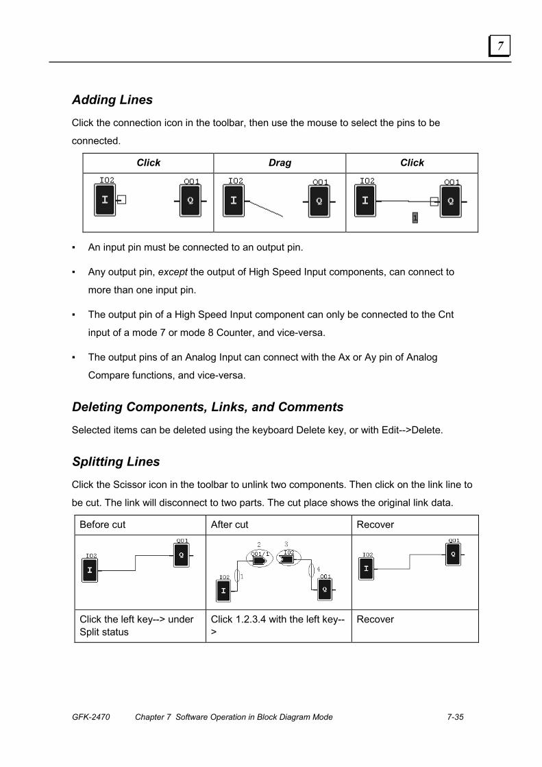
GFK-2470 Chapter 7 Software Operation in Block Diagram Mode 7-35
7
Adding Lines Click the connection icon in the toolbar, then use the mouse to select the pins to be
connected.
Click Drag Click
▪ An input pin must be connected to an output pin.
▪ Any output pin, except the output of High Speed Input components, can connect to
more than one input pin.
▪ The output pin of a High Speed Input component can only be connected to the Cnt
input of a mode 7 or mode 8 Counter, and vice-versa.
▪ The output pins of an Analog Input can connect with the Ax or Ay pin of Analog
Compare functions, and vice-versa.
Deleting Components, Links, and Comments Selected items can be deleted using the keyboard Delete key, or with Edit-->Delete.
Splitting Lines Click the Scissor icon in the toolbar to unlink two components. Then click on the link line to
be cut. The link will disconnect to two parts. The cut place shows the original link data.
Before cut After cut Recover
Click the left key--> under Split status
Click 1.2.3.4 with the left key-->
Recover
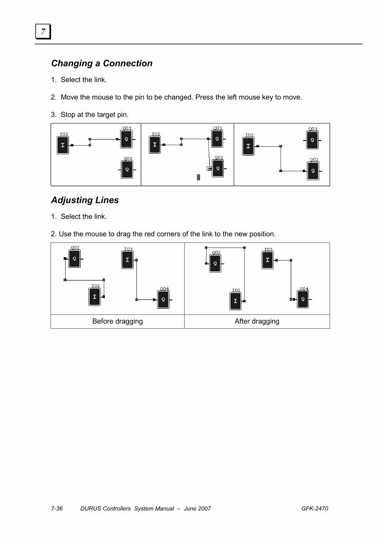
7-36 DURUS Controllers System Manual – June 2007 GFK-2470
7
Changing a Connection 1. Select the link.
2. Move the mouse to the pin to be changed. Press the left mouse key to move.
3. Stop at the target pin.
Adjusting Lines 1. Select the link.
2. Use the mouse to drag the red corners of the link to the new position.
Before dragging After dragging
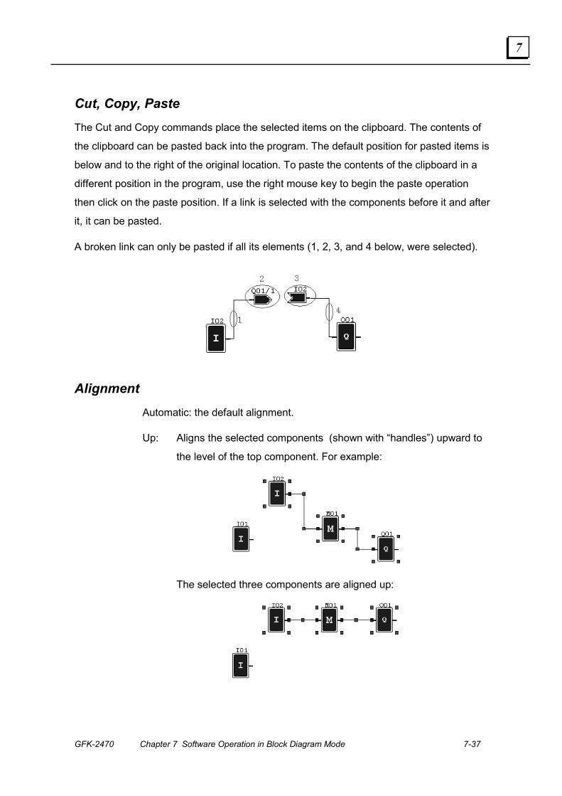
GFK-2470 Chapter 7 Software Operation in Block Diagram Mode 7-37
7
Cut, Copy, Paste The Cut and Copy commands place the selected items on the clipboard. The contents of
the clipboard can be pasted back into the program. The default position for pasted items is
below and to the right of the original location. To paste the contents of the clipboard in a
different position in the program, use the right mouse key to begin the paste operation
then click on the paste position. If a link is selected with the components before it and after
it, it can be pasted.
A broken link can only be pasted if all its elements (1, 2, 3, and 4 below, were selected).
Alignment Automatic: the default alignment.
Up: Aligns the selected components (shown with “handles”) upward to
the level of the top component. For example:
The selected three components are aligned up:
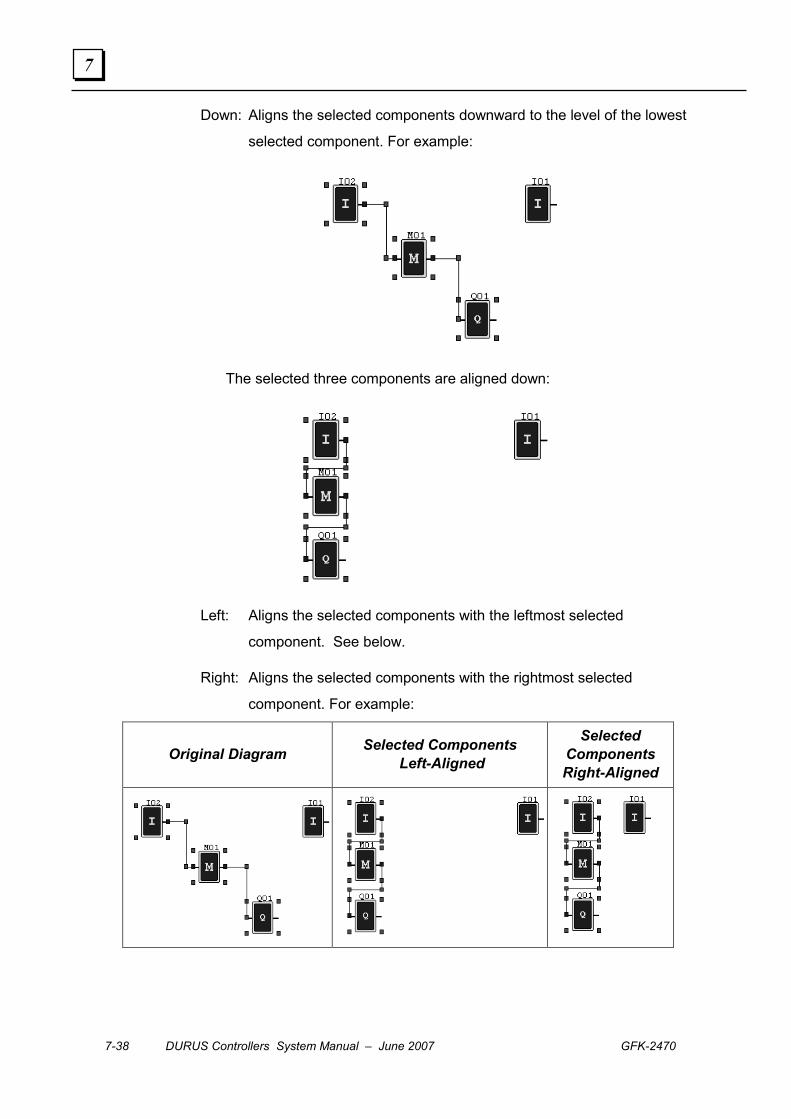
7-38 DURUS Controllers System Manual – June 2007 GFK-2470
7
Down: Aligns the selected components downward to the level of the lowest
selected component. For example:
The selected three components are aligned down:
Left: Aligns the selected components with the leftmost selected
component. See below.
Right: Aligns the selected components with the rightmost selected
component. For example:
Original Diagram Selected Components Left-Aligned
Selected Components Right-Aligned
GFK-2470 8-1
MODBUS Communications
This chapter describes the MODBUS features that can be incorporated into a Durus
controller system by adding a MODBUS RTU Slave Communications Expansion Module,
24VDC (IC210EMS001).
▪ Overview
▪ The Profibus Expansion Module
▪ Specifications
▪ Operation
▪ Installation
▪ Operation
▪ The GSD File
▪ Input / Output Data
▪ Control Commands
Chapter
8
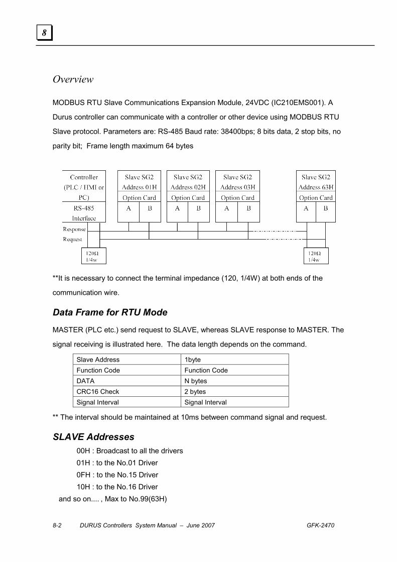
8-2 DURUS Controllers System Manual – June 2007 GFK-2470
8
Overview
MODBUS RTU Slave Communications Expansion Module, 24VDC (IC210EMS001). A
Durus controller can communicate with a controller or other device using MODBUS RTU
Slave protocol. Parameters are: RS-485 Baud rate: 38400bps; 8 bits data, 2 stop bits, no
parity bit; Frame length maximum 64 bytes
**It is necessary to connect the terminal impedance (120, 1/4W) at both ends of the
communication wire.
Data Frame for RTU Mode
MASTER (PLC etc.) send request to SLAVE, whereas SLAVE response to MASTER. The
signal receiving is illustrated here. The data length depends on the command.
Slave Address 1byte Function Code Function Code DATA N bytes CRC16 Check 2 bytes Signal Interval Signal Interval
** The interval should be maintained at 10ms between command signal and request.
SLAVE Addresses 00H : Broadcast to all the drivers 01H : to the No.01 Driver 0FH : to the No.15 Driver 10H : to the No.16 Driver and so on.... , Max to No.99(63H)
GFK-2470 Chapter 8 MODBUS Communications 8-3
8
Supported MODBUS Function Codes
Durus controllers support the following MOCBUS function codes:
01H : Read Coils Status 03H : Read register data 05H : Write single coil 06H : Write a word to register memory 08H : Loopback check 10H : Write register data.
CMS (Checksum and time-out definition)
CRC CHECK:
CRC check code is from Slave Address to end of the data. The calculation method is
illustrated as follows:
(1) Load a 16-bit register with FFFF hex (all1’s). Call this the CRC register.
(2) Exclusive OR the first 8-bit byte of the message with the low-order byte of the 16-bit
CRC register, putting the result in the CRC register.
(3) Shift the CRC register one bit to the right (toward the LSB), Zero-filling the MSB,
Extract and examines the LSB.
(4) (If the LSB was 0): Repeat Steps (3) (another shift) (If the LSB was 1): Exclusive
OR the CRC register with the polynomial value A001 hex (1010 0000 0000 0001).
(5) Repeat Steps (3) and (4) until 8 shifts have been performed. When this is done, a
complete 8-bit byte will be processed.
(6) Repeat Steps (2) through (5) for next 8-bit byte of the message, Continue doing this
until all bytes have been processed. The final content of the CRC register is the
CRC value. Placing the CRC into the message: When the 16-bit CRC (2 8-bit bytes)
is transmitted in the message, the low-order byte will be transmitted first, followed
by the high-order byte. For example, if the CRC value is 1241 hex, the CRC-16 is
(Low) put 41h, if the CRC-16 is (High) put12h.
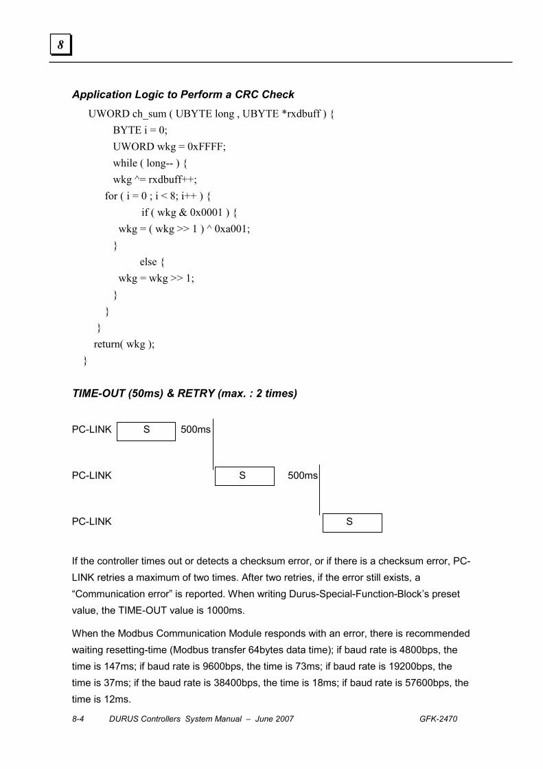
8-4 DURUS Controllers System Manual – June 2007 GFK-2470
8
Application Logic to Perform a CRC Check UWORD ch_sum ( UBYTE long , UBYTE *rxdbuff ) { BYTE i = 0; UWORD wkg = 0xFFFF; while ( long-- ) { wkg ^= rxdbuff++; for ( i = 0 ; i < 8; i++ ) { if ( wkg & 0x0001 ) { wkg = ( wkg >> 1 ) ^ 0xa001; } else { wkg = wkg >> 1; } } } return( wkg ); } TIME-OUT (50ms) & RETRY (max. : 2 times)
PC-LINK S 500ms
PC-LINK S 500ms
PC-LINK S
If the controller times out or detects a checksum error, or if there is a checksum error, PC-LINK retries a maximum of two times. After two retries, if the error still exists, a “Communication error” is reported. When writing Durus-Special-Function-Block’s preset value, the TIME-OUT value is 1000ms.
When the Modbus Communication Module responds with an error, there is recommended waiting resetting-time (Modbus transfer 64bytes data time); if baud rate is 4800bps, the time is 147ms; if baud rate is 9600bps, the time is 73ms; if baud rate is 19200bps, the time is 37ms; if the baud rate is 38400bps, the time is 18ms; if baud rate is 57600bps, the time is 12ms.

GFK-2470 Chapter 8 MODBUS Communications 8-5
8
Commands
Read Coils, Command 01
The MODBUS master can issue MODBUS RTU command 01 to read the value of one or
more coils in the slave Durus controller.
Read Registers, Command 03
The MODBUS master can issue MODBUS RTU command 03 to read the value of one or
more registers in the slave Durus controller.
Master Command Slave Address 01H Function Code 01H
High 05H *Register Address Low 40H
High 00H Nomber of Coils Low 10H
Low 3CH CRC-16 High DEH
Normal Slave Response Address 01H Function Code 01H Byte Count 02H Outputs status M8-1 45H Outputs status MF-9 34H
Low 3AH CRC-16 High BBH
Error Slave Response Address 01H Function Code 81H Exception Code 51H
Low 81H CRC-16 High ACH
Master Command Address 01H Function Code 03H
High 00H *Register Address Low 00H
High 00H Data Length Low 13H Low 04H CRC-16 High 07H
Normal Slave Response Address 01H Function Code 03HData (byte) 00HSend the data
Low ? CRC-16 High ?
Error Slave Response Address 01H Function Code 83H Exception Code 52H
Low C0H CRC-16 High CDH
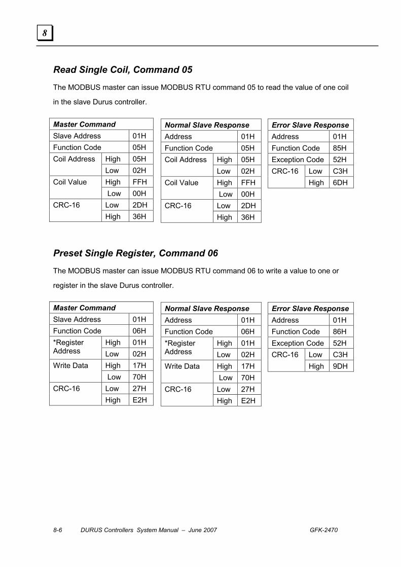
8-6 DURUS Controllers System Manual – June 2007 GFK-2470
8
Read Single Coil, Command 05
The MODBUS master can issue MODBUS RTU command 05 to read the value of one coil
in the slave Durus controller.
Preset Single Register, Command 06
The MODBUS master can issue MODBUS RTU command 06 to write a value to one or
register in the slave Durus controller.
Master Command Slave Address 01H Function Code 05H
High 05H Coil Address Low 02H High FFH Coil Value Low 00H Low 2DH CRC-16 High 36H
Normal Slave Response Address 01H Function Code 05H
High 05H Coil Address Low 02H High FFH Coil Value Low 00H Low 2DH CRC-16 High 36H
Error Slave Response Address 01H Function Code 85H Exception Code 52H
Low C3H CRC-16 High 6DH
Master Command Slave Address 01H Function Code 06H
High 01H *Register Address Low 02H
High 17H Write Data Low 70H Low 27H CRC-16 High E2H
Normal Slave Response Address 01H Function Code 06H
High 01H *Register Address Low 02H
High 17H Write Data Low 70H Low 27H CRC-16 High E2H
Error Slave Response Address 01H Function Code 86H Exception Code 52H
Low C3H CRC-16 High 9DH

GFK-2470 Chapter 8 MODBUS Communications 8-7
8
Loopback Check, Command 08
The MODBUS master can issue MODBUS RTU command 08 to test the slave Durus
controller’s ability to communicate. The content of the Data word is not meaningful.
Write Registers, Command 10
The MODBUS master can issue MODBUS RTU command 10 to write a group of 1 to
approximately 27 registers in the slave Durus controller.
Master Command Slave Address 01H Function Code 08H
High 00H Check Code Low 00H High A5H Data Low 37H Low DAH CRC-16 High 8DH
Normal Slave Response Slave Address 01H Function Code 08H
High 00H Check Code Low 00H High A5H Data Low 37H Low DAH CRC-16 High 8DH
Error Slave Response Slave Address 01H Function Code 88H Exception Code 20H
Low 47H CRC-16 High D8H
Master Command Address 01H Function Code 10H
High 00H *Register Address Low 00H
High 00H Data Length Low 13H
Byte Counters 26H Data Content
Low ? CRC-16 High ?
Normal Slave Response Slave Address 01H Function Code 10H
High 00H *Register Address Low 00H
High 00H Data Length Low 13H High 81H CRC-16 Low C4H
Error Slave Response Slave Address 01H Function Code 90H Exception Code 52H
Low ACH CRC-16 High 3DH
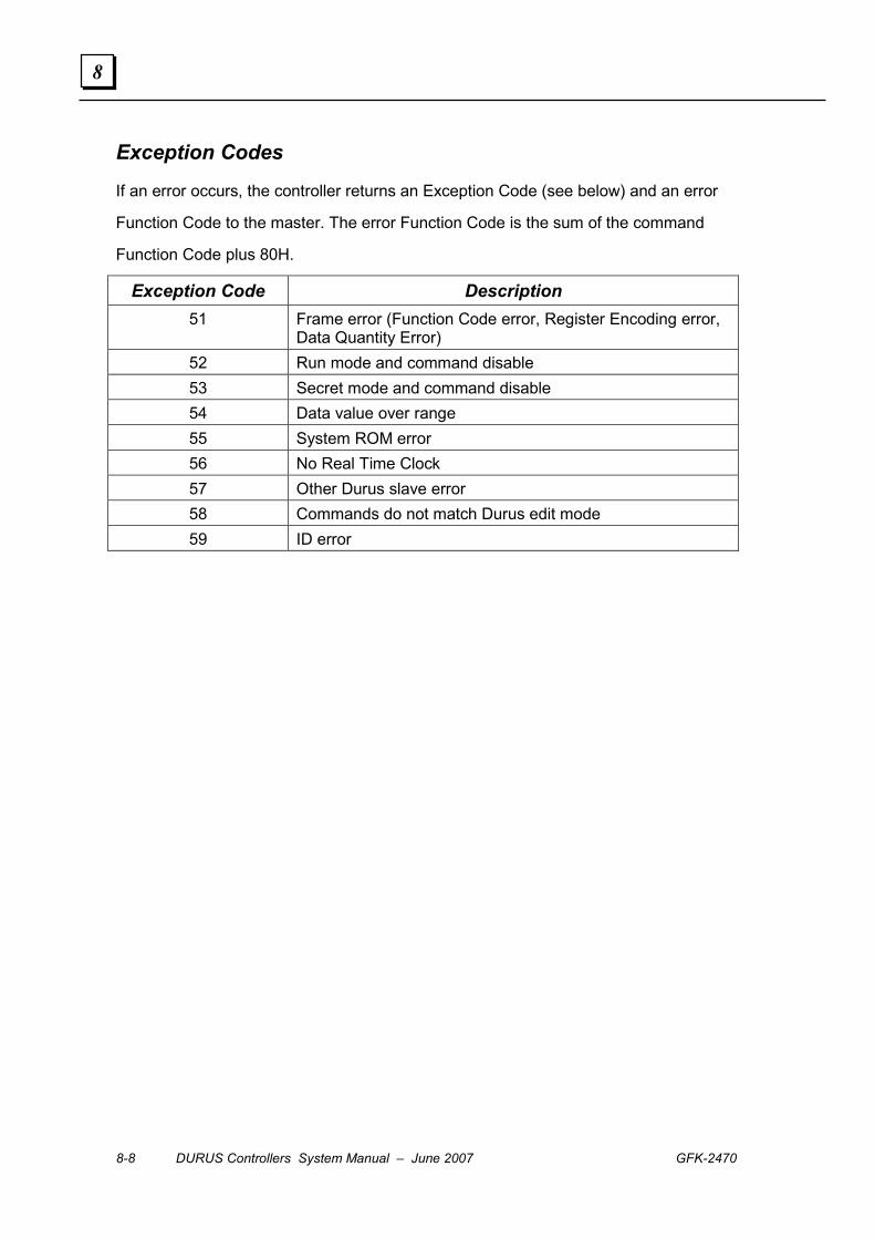
8-8 DURUS Controllers System Manual – June 2007 GFK-2470
8
Exception Codes
If an error occurs, the controller returns an Exception Code (see below) and an error
Function Code to the master. The error Function Code is the sum of the command
Function Code plus 80H.
Exception Code Description 51 Frame error (Function Code error, Register Encoding error,
Data Quantity Error) 52 Run mode and command disable 53 Secret mode and command disable 54 Data value over range 55 System ROM error 56 No Real Time Clock 57 Other Durus slave error 58 Commands do not match Durus edit mode 59 ID error
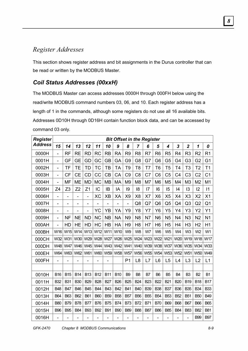
GFK-2470 Chapter 8 MODBUS Communications 8-9
8
Register Addresses
This section shows register address and bit assignments in the Durus controller that can
be read or written by the MODBUS Master.
Coil Status Addresses (00xxH)
The MODBUS Master can access addresses 0000H through 000FH below using the
read/write MODBUS command numbers 03, 06, and 10. Each register address has a
length of 1 in the commands, although some registers do not use all 16 available bits.
Addresses 0D10H through 0D16H contain function block data, and can be accessed by
command 03 only.
Bit Offset in the Register Register Address 15 14 13 12 11 10 9 8 7 6 5 4 3 2 1 0 0000H - RF RE RD RC RB RA R9 R8 R7 R6 R5 R4 R3 R2 R10001H - GF GE GD GC GB GA G9 G8 G7 G6 G5 G4 G3 G2 G10002H - TF TE TD TC TB TA T9 T8 T7 T6 T5 T4 T3 T2 T10003H - CF CE CD CC CB CA C9 C8 C7 C6 C5 C4 C3 C2 C10004H - MF ME MD MC MB MA M9 M8 M7 M6 M5 M4 M3 M2 M10005H Z4 Z3 Z2 Z1 IC IB IA I9 I8 I7 I6 I5 I4 I3 I2 I1 0006H - - - - XC XB XA X9 X8 X7 X6 X5 X4 X3 X2 X10007H - - - - - - - - Q8 Q7 Q6 Q5 Q4 Q3 Q2 Q10008H - - - - YC YB YA Y9 Y8 Y7 Y6 Y5 Y4 Y3 Y2 Y10009H - NF NE ND NC NB NA N9 N8 N7 N6 N5 N4 N3 N2 N1000AH - HD HE HD HC HB HA H9 H8 H7 H6 H5 H4 H3 H2 H1000BH W16 W15 W14 W13 W12 W11 W10 W9 W8 W7 W6 W5 W4 W3 W2 W1
000CH W32 W31 W30 W29 W28 W27 W26 W25 W24 W23 W22 W21 W20 W19 W18 W17
000DH W48 W47 W46 W45 W44 W43 W42 W41 W40 W39 W38 W37 W36 W35 W34 W33
000EH W64 W63 W62 W61 W60 W59 W58 W57 W56 W55 W54 W53 W52 W51 W50 W49
000FH - - - - - - P1 L8 L7 L6 L5 L4 L3 L2 L1
0010H B16 B15 B14 B13 B12 B11 B10 B9 B8 B7 B6 B5 B4 B3 B2 B1
0011H B32 B31 B30 B29 B28 B27 B26 B25 B24 B23 B22 B21 B20 B19 B18 B17
0012H B48 B47 B46 B45 B44 B43 B42 B41 B40 B39 B38 B37 B36 B35 B34 B33
0013H B64 B63 B62 B61 B60 B59 B58 B57 B56 B55 B54 B53 B52 B51 B50 B49
0014H B80 B79 B78 B77 B76 B75 B74 B73 B72 B71 B70 B69 B68 B67 B66 B65
0015H B96 B95 B84 B93 B92 B91 B90 B89 B88 B87 B86 B85 B84 B83 B82 B81
0016H - - - - - - - - - - - - - - B99 B97
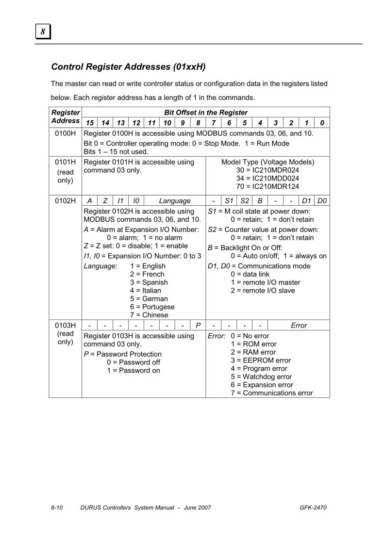
8-10 DURUS Controllers System Manual – June 2007 GFK-2470
8
Control Register Addresses (01xxH)
The master can read or write controller status or configuration data in the registers listed
below. Each register address has a length of 1 in the commands.
Bit Offset in the Register Register Address 15 14 13 12 11 10 9 8 7 6 5 4 3 2 1 0 0100H
Register 0100H is accessible using MODBUS commands 03, 06, and 10. Bit 0 = Controller operating mode: 0 = Stop Mode. 1 = Run Mode Bits 1 – 15 not used.
0101H (read only)
Register 0101H is accessible using command 03 only.
Model Type (Voltage Models) 30 = IC210MDR024 34 = IC210MDD024 70 = IC210MDR124
A Z I1 I0 Language - S1 S2 B - - D1 D00102H Register 0102H is accessible using
MODBUS commands 03, 06, and 10. A = Alarm at Expansion I/O Number: 0 = alarm; 1 = no alarm Z = Z set: 0 = disable; 1 = enable I1, I0 = Expansion I/O Number: 0 to 3 Language: 1 = English 2 = French 3 = Spanish 4 = Italian 5 = German 6 = Portugese 7 = Chinese
S1 = M coil state at power down: 0 = retain; 1 = don’t retain S2 = Counter value at power down: 0 = retain; 1 = don’t retain B = Backlight On or Off: 0 = Auto on/off; 1 = always onD1, D0 = Communications mode 0 = data link 1 = remote I/O master 2 = remote I/O slave
- - - - - - - P - - - - Error 0103H (read only)
Register 0103H is accessible using command 03 only. P = Password Protection 0 = Password off 1 = Password on
Error: 0 = No error 1 = ROM error 2 = RAM error 3 = EEPROM error 4 = Program error 5 = Watchdog error 6 = Expansion error 7 = Communications error
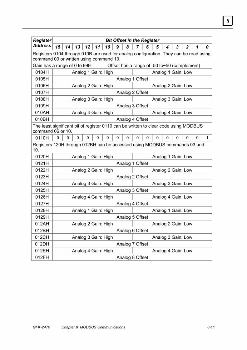
GFK-2470 Chapter 8 MODBUS Communications 8-11
8
Bit Offset in the Register Register Address 15 14 13 12 11 10 9 8 7 6 5 4 3 2 1 0 Registers 0104 through 010B are used for analog configuration. They can be read using command 03 or written using command 10. Gain has a range of 0 to 999. Offset has a range of -50 to~50 (complement)
0104H Analog 1 Gain: High Analog 1 Gain: Low 0105H Analog 1 Offset 0106H Analog 2 Gain: High Analog 2 Gain: Low 0107H Analog 2 Offset 0108H Analog 3 Gain: High Analog 3 Gain: Low 0109H Analog 3 Offset 010AH Analog 4 Gain: High Analog 4 Gain: Low 010BH Analog 4 Offset
The least significant bit of register 0110 can be written to clear code using MODBUS command 06 or 10.
0110H 0 0 0 0 0 0 0 0 0 0 0 0 0 0 0 1
Registers 120H through 012BH can be accessed using MODBUS commands 03 and 10.
0120H Analog 1 Gain: High Analog 1 Gain: Low 0121H Analog 1 Offset 0122H Analog 2 Gain: High Analog 2 Gain: Low 0123H Analog 2 Offset 0124H Analog 3 Gain: High Analog 3 Gain: Low 0125H Analog 3 Offset 0126H Analog 4 Gain: High Analog 4 Gain: Low 0127H Analog 4 Offset 0128H Analog 1 Gain: High Analog 1 Gain: Low 0129H Analog 5 Offset 012AH Analog 2 Gain: High Analog 2 Gain: Low 012BH Analog 6 Offset 012CH Analog 3 Gain: High Analog 3 Gain: Low 012DH Analog 7 Offset 012EH Analog 4 Gain: High Analog 4 Gain: Low 012FH Analog 8 Offset

8-12 DURUS Controllers System Manual – June 2007 GFK-2470
8
Current Values Registers (02xxH)
The master can use MODBUS command 03 to read current function values in the
registers listed below. For the Real-Time Clock current values (0220H – 022AH) only,
MODBUS command 10 can also be used to write clock data.
Register Address
Length Description
0200H 1 Timer 1 Current Value - - - - - - - - - - - - - - - - - - - - - 020EH 1 Timer F Current Value
Registers 0210 through 021E contain the counter current value. Range is 0 to 999999 decimal, 0 to 0F423F hexadecimal.
Counter 1 Value, Middle Counter 1 Value, Low 0210H 2 00 Counter 1 Value, High
0211H 2 Counter 2 Current Value, see Counter 1 format - - - - - - - - - - - - - - - - - - - - - 021EH 2 Counter F Current Value, see Counter 1 format
Registers 0220 through 0223 contain the Real Time Clock Current Value. 0220H 1 Current Year Current Month 0221H 1 Current Day Current Week 0222H 1 Current Hour Current Minute 0223H 1 Current Second 00 0224H 1 00 Current Year 0225H 1 00 Current Month 0226H 1 00 Current Day 0227H 1 00 Current Week 0228H 1 00 Current Hour 0229H 1 00 Current Minute 022AH 1 00 Current Second
Registers 0230 through 0237 contain the analog values. 0230H 1 Analog 1 High Value Analog 1 Low Value
- - - - - - - - - - - - - - - - - - - - - 0237H 1 Analog 8 High Value Analog 8 Low Value
Register 0260 contains the PWM current values.
00 PWM Run Number Pulse Width High Pulse Width Low
0260H 1
Period Time High Period Time Low
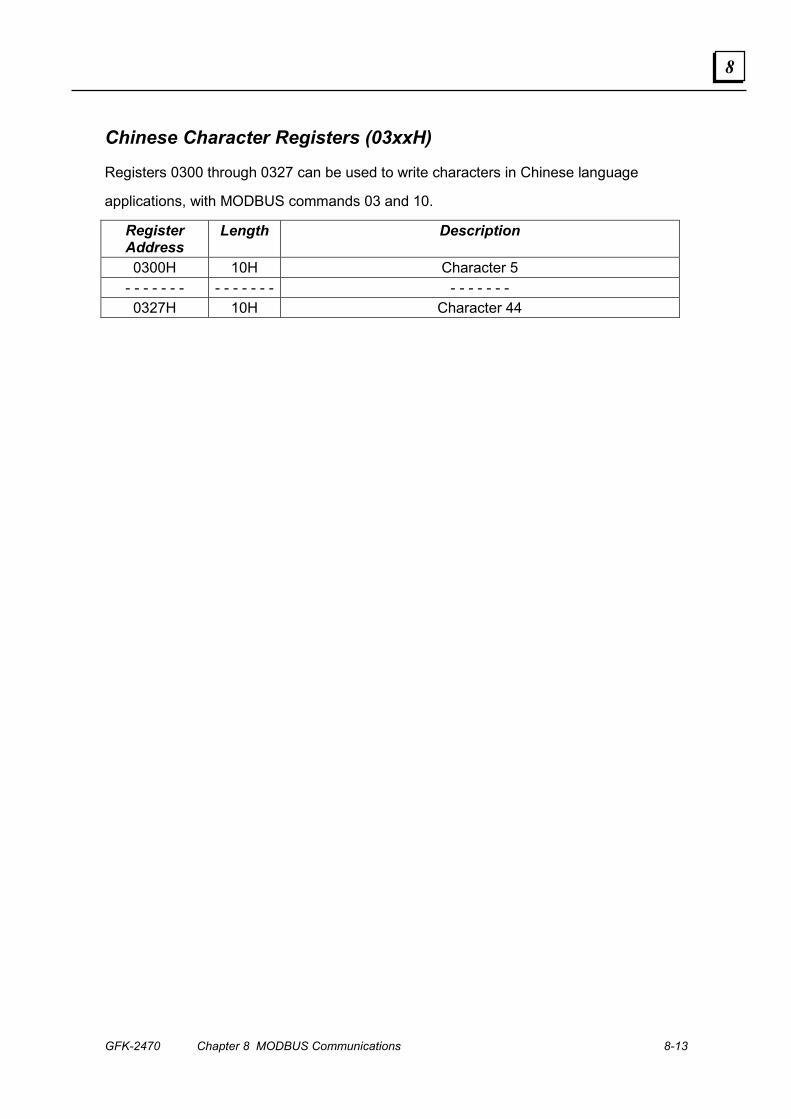
GFK-2470 Chapter 8 MODBUS Communications 8-13
8
Chinese Character Registers (03xxH)
Registers 0300 through 0327 can be used to write characters in Chinese language
applications, with MODBUS commands 03 and 10.
Register Address
Length Description
0300H 10H Character 5 - - - - - - - - - - - - - - - - - - - - - 0327H 10H Character 44

8-14 DURUS Controllers System Manual – June 2007 GFK-2470
8
Preset Values Registers (04xxH)
The master can read or write Preset values in the registers listed below using MODBUS
commands 03 and 10.
Register Address
Length Description
0400H 1 Timer 1 Preset Value - - - - - - - - - - - - - - - - - - - - - 040EH 1 Timer F Preset Value
Registers 0410 through 041E contain Counter Preset value. Range is 0 to 999999 decimal, 0 to 0F423F hexadecimal.
Preset Data Format for Counter Modes 1 to 7 Counter 1 Preset, Middle Counter 1 Preset, Low
2
00 Counter 1 Preset, High Preset Data Format for Counter Mode 8
Fixed Timer High Fixed Timer Low Counter ON Preset, Middle Counter ON Preset, Low
00 Counter ON Preset, High Counter OFF Preset, Middle Counter OFF Preset, Low
0410H
5
00 Counter OFF Preset, High - - - - - - - - - - - - - - - - - - - - - 041EH 2/5 Counter F Preset, see Counter 1 formats
Registers 0420 through 042E contain the Real Time Clock Preset Value. 0420H 3 RTC Mode 1 or RTC Mode 2
Turn On Week (00-06) Turn Off Week (00-06) Turn On Time, Hour (00-23) Turn On Time, Minute (00-59) Turn Off Time, Hour (00-23) Turn Off Time, Minute(00-59) RTC Mode 3 Turn On Year (00-99) Turn Off Year (00-99) Turn On Month (01-12) Turn On Day (01 to 31) Turn Off Month (01-12) Turn Off Day (01-31) RTC Mode 4: 30-second adjustment 00 Round time: week Round time: hour Round time: minute 00 Round time: second
- - - - - - - - - - - - - - - - - - - - - 042EH 3 RTC Preset F, See RTC Preset 1 formats
Registers 0430 through 043E contain the analog values. 0430H 1 Analog 1 High Value Analog 1 Low Value
- - - - - - - - - - - - - - - - - - - - - - - - - - - - 043EH 1 Analog 8 High Value Analog 8 Low Value

GFK-2470 Chapter 8 MODBUS Communications 8-15
8
Preset Values Registers (04xxH) (continued) Registers 0460 to 046E contain the PWM Preset values. Pulse Width Range is 00000 to
32767. Period Time range is 00001 to 32767. They can be accessed using MODBUS
commands 01 and 05.
Register Address
Length Description
0460H 10 Pulse Width 1 High Pulse Width 1 Low 0461H Period Time 1 High Period Time 1 Low 0462H Pulse Width 2 High Pulse Width 2 Low 0463H Period Time 2 High Period Time 2 Low 0464H Pulse Width 3 High Pulse Width 3 Low 0465H Period Time 3 High Period Time 3 Low 0466H Pulse Width 4 High Pulse Width 4 Low 0467H Period Time 4 High Period Time 4 Low 0468H Pulse Width 5 High Pulse Width 5 Low 0469H Period Time 5 High Period Time 5 Low 046AH Pulse Width 6 High Pulse Width 6 Low 046BH Period Time 6 High Period Time 6 Low 046CH Pulse Width 7 High Pulse Width 7 Low 046DH Period Time 7 High Period Time 7 Low 046EH Pulse Width 8 High Pulse Width 8 Low 046FH Period Time 8 High Period Time 8 Low

8-16 DURUS Controllers System Manual – June 2007 GFK-2470
8
Coils Address (05xxH)
The master use MODBUS command 01 or 05 to read or write Coil values in the registers
listed below. Starting address and quantity of coils are multiples of 10H.
Register Address
Length Description
0500H-050FH 10H R1 – RF 050FH reserved 0510H-051FH 10H G1 – GF 051FH reserved 0520H-052FH 10H T1 – TF 052FH reserved 0530H-053FH 10H C1 –CF 053FH reserved 0540H-054FH 10H M1 –MF 054FH reserved 0550H-055FH 10H I1 –IC, Z1 - ZF Z1 to Z4 cannot be written 0560H-056FH 10H X1 –XC 056CH – 056FH reserved 0570H-057FH 10H Q1 –Q8 0578H - 057FH reserved 0580H-058FH 10H Y1 –YC 058CH - 058FH reserved 0590H-059FH 10H N1 –NF 059FH reserved 05A0H-05AFH 10H H1 –HF 0A5FH reserved 05B0H-05BFH 10H W1 –W16 05C0H-05CFH 10H W17 –W32 05D0H-05DFH 10H W33 –W48 05E0H-05EFH 10H W49 –W64
05F0H-05FFH 10H L1 – L8, P1 05F9H - 05FFH reserved

GFK-2470 9-1
Profibus Communications
This chapter describes the Profibus-DP features that can be incorporated into a Durus
controller system by including a Profibus-DP Slave Communications Expansion Module,
24VDC (IC210EPS001).
▪ Overview
▪ The Profibus Expansion Module
▪ Specifications
▪ Operation
▪ Installation
▪ Startup
▪ The GSD File
▪ Control Commands
9 Chapter
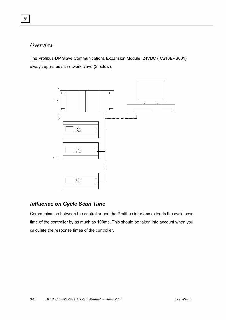
9-2 DURUS Controllers System Manual – June 2007 GFK-2470
9
Overview
The Profibus-DP Slave Communications Expansion Module, 24VDC (IC210EPS001)
always operates as network slave (2 below).
Influence on Cycle Scan Time
Communication between the controller and the Profibus interface extends the cycle scan
time of the controller by as much as 100ms. This should be taken into account when you
calculate the response times of the controller.
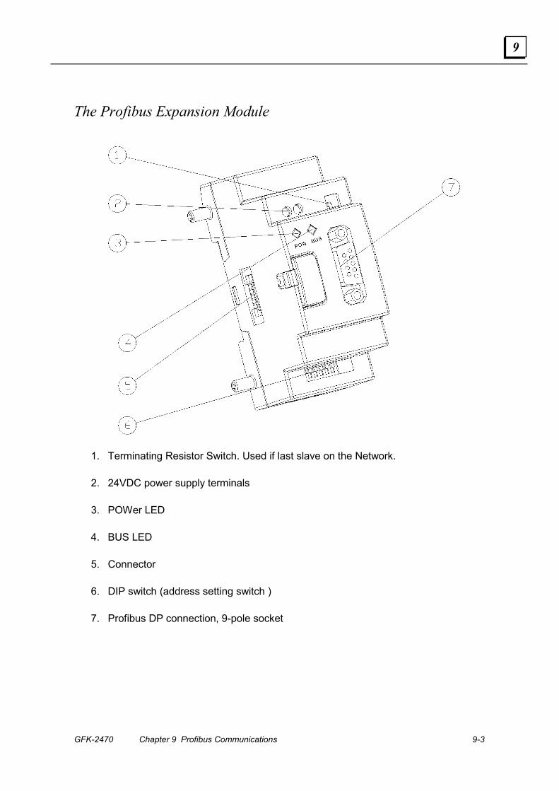
GFK-2470 Chapter 9 Profibus Communications 9-3
9
The Profibus Expansion Module
1. Terminating Resistor Switch. Used if last slave on the Network.
2. 24VDC power supply terminals
3. POWer LED
4. BUS LED
5. Connector
6. DIP switch (address setting switch )
7. Profibus DP connection, 9-pole socket
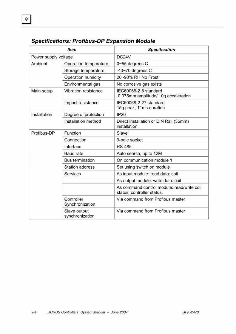
9-4 DURUS Controllers System Manual – June 2007 GFK-2470
9
Specifications: Profibus-DP Expansion Module Item Specification
Power supply voltage DC24V Operation temperature 0~55 degrees C Storage temperature -40~70 degrees C Operation humidity 20~90% RH No Frost
Ambient
Environmental gas No corrosive gas exists Vibration resistance IEC60068-2-6 standard
0.075mm amplitude/1.0g acceleration Main setup
Impact resistance IEC60068-2-27 standard 15g peak, 11ms duration
Degree of protection IP20 Installation Installation method Direct installation or DIN Rail (35mm)
installation Function Slave Connection 9-pole socket Interface RS-485 Baud rate Auto search, up to 12M Bus termination On communication module 1 Station address Set using switch on module Services As input module: read data: coil As output module: write data: coil As command control module: read/write coli
status, controller status. Controller Synchronization
Via command from Profibus master
Profibus-DP
Slave output synchronization
Via command from Profibus master

GFK-2470 Chapter 9 Profibus Communications 9-5
9
Operation
The following data can be transferred if appropriate module in GSD file is selected.
▪ Data that can be read by the Profibus-DP master
All coils: I1-IC, X1-XC, M1-MF, Q1-Q8, Y1-YC, T1-TF, C1-CF, G1-GF, R1-RF
T1-TF’s current value and preset value
C1-CF’s current value and preset value
G1-GF’s current value and preset value
RTC’s current value and R1-RF’s preset value
PWM’s current value and preset value
Controller’s Run/Stop status
▪ Data that can be written by the Profibus-DP master
Coils: M1-MF, Q1-Q8, Y1-YC, T1-TF, C1-CF, G1-GF, R1-RF
T1-TF’s preset value
C1-CF’s preset value
G1-GF’s preset value
RTC’s current value and R1-RF’s preset value
PWM’s preset value
Controller’s Run/Stop status

9-6 DURUS Controllers System Manual – June 2007 GFK-2470
9
Installation
1. Connect the expansion connector to the Profibus-DP Slave expansion module.
2. Connect the expansion module to the controller module. See chapter 2 for
additional installation instructions.
There can be at most three I/O expansion modules and one 4AI expansion modules
between the Profibus-DP Expansion module and the controller.
The number of I/O modules in the setup menu of the controller must match the number of
connected modules.
Power Supply Connection
The module requires an external source of 24VDC power.

GFK-2470 Chapter 9 Profibus Communications 9-7
9
Profibus-DP Bus Connection
Use a 9-pole Profibus-DP plug and cable to connect the Profibus Expansion Module to the
Profibus-DP field bus. The type of cable used has an influence on the maximum available
length of the bus line and thus on the data transfer rate.
Pin Signal name Description 1 Unused 2 Unused 3 RxD/TxD-P (B- Line) Send/receive data (positive) 4 Unused 5 DGND (2M) Data reference potential
6 VP (2 P5) +5V DC
7 Unused 8 RxD/TxD-N (A-Line) Send/receive data (negative) 9 Unused
Bus Termination
The first and last station in a bus segment must be terminated. If the Profibus-DP
Expansion module is at the end of a bus segment, set the termination switches on the
front of the module to the On position.
SW2 – 1 SW2 – 2 Termination Off Off Off On On On
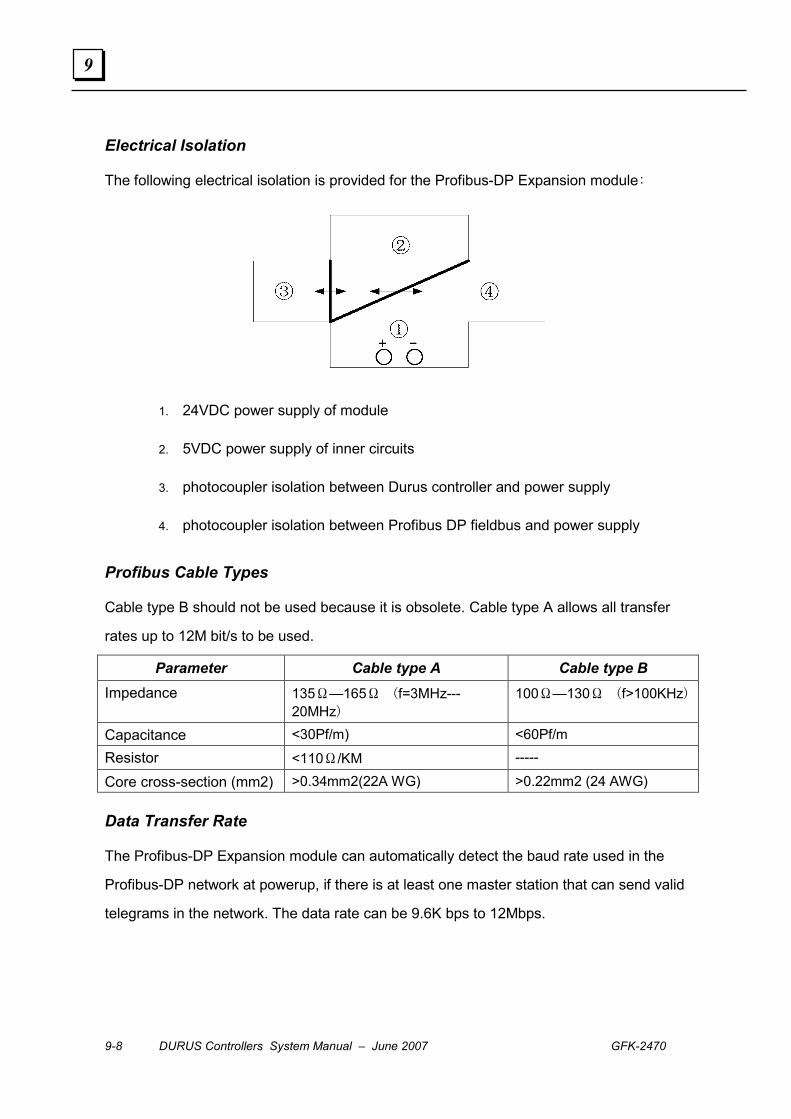
9-8 DURUS Controllers System Manual – June 2007 GFK-2470
9
Electrical Isolation
The following electrical isolation is provided for the Profibus-DP Expansion module:
1. 24VDC power supply of module
2. 5VDC power supply of inner circuits
3. photocoupler isolation between Durus controller and power supply
4. photocoupler isolation between Profibus DP fieldbus and power supply
Profibus Cable Types
Cable type B should not be used because it is obsolete. Cable type A allows all transfer
rates up to 12M bit/s to be used.
Parameter Cable type A Cable type B Impedance 135Ω—165Ω (f=3MHz---
20MHz) 100Ω—130Ω (f>100KHz)
Capacitance <30Pf/m) <60Pf/m
Resistor <110Ω/KM -----
Core cross-section (mm2) >0.34mm2(22A WG) >0.22mm2 (24 AWG)
Data Transfer Rate
The Profibus-DP Expansion module can automatically detect the baud rate used in the
Profibus-DP network at powerup, if there is at least one master station that can send valid
telegrams in the network. The data rate can be 9.6K bps to 12Mbps.
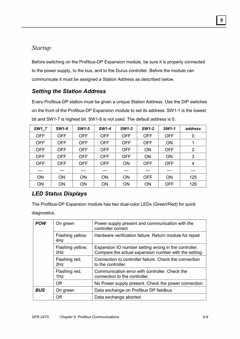
GFK-2470 Chapter 9 Profibus Communications 9-9
9
Startup
Before switching on the Profibus-DP Expansion module, be sure it is properly connected
to the power supply, to the bus, and to the Durus controller. Before the module can
communicate it must be assigned a Station Address as described below.
Setting the Station Address
Every Profibus-DP station must be given a unique Station Address. Use the DIP switches
on the front of the Profibus-DP Expansion module to set its address. SW1-1 is the lowest
bit and SW1-7 is highest bit. SW1-8 is not used. The default address is 0.
SW1_7 SW1-6 SW1-5 SW1-4 SW1-3 SW1-2 SW1-1 address
OFF OFF OFF OFF OFF OFF OFF 0 OFF OFF OFF OFF OFF OFF ON 1 OFF OFF OFF OFF OFF ON OFF 2 OFF OFF OFF OFF OFF ON ON 3 OFF OFF OFF OFF ON OFF OFF 4 --- --- --- --- --- --- --- --- ON ON ON ON ON OFF ON 125 ON ON ON ON ON ON OFF 126
LED Status Displays
The Profibus-DP Expansion module has two dual-color LEDs (Green/Red) for quick
diagnostics.
On green Power supply present and communication with the controller correct
Flashing yellow 4Hz
Hardware verification failure. Return module for repair
Flashing yellow, 2Hz
Expansion IO number setting wrong in the controller. Compare the actual expansion number with the setting.
Flashing red, 2Hz
Connection to controller failure. Check the connection to the controller.
Flashing red, 1Hz
Communication error with controller. Check the connection to the controller.
POW
Off No Power supply present. Check the power connection.On green Data exchange on Profibus DP fieldbus BUS Off Data exchange aborted
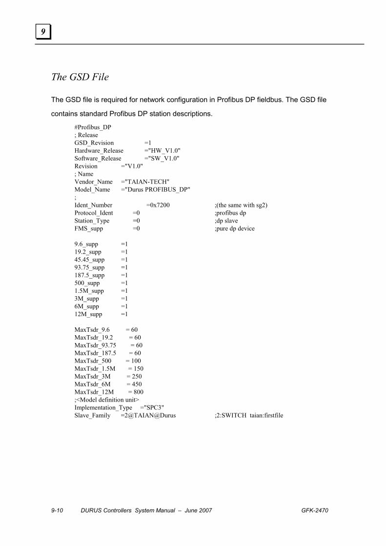
9-10 DURUS Controllers System Manual – June 2007 GFK-2470
9
The GSD File
The GSD file is required for network configuration in Profibus DP fieldbus. The GSD file
contains standard Profibus DP station descriptions.
#Profibus_DP ; Release GSD_Revision =1 Hardware_Release ="HW_V1.0" Software_Release ="SW_V1.0" Revision ="V1.0" ; Name Vendor_Name ="TAIAN-TECH" Model_Name ="Durus PROFIBUS_DP" ; Ident_Number =0x7200 ;(the same with sg2) Protocol_Ident =0 ;profibus dp Station_Type =0 ;dp slave FMS_supp =0 ;pure dp device 9.6_supp =1 19.2_supp =1 45.45_supp =1 93.75_supp =1 187.5_supp =1 500_supp =1 1.5M_supp =1 3M_supp =1 6M_supp =1 12M_supp =1 MaxTsdr_9.6 = 60 MaxTsdr_19.2 = 60 MaxTsdr_93.75 = 60 MaxTsdr_187.5 = 60 MaxTsdr_500 = 100 MaxTsdr_1.5M = 150 MaxTsdr_3M = 250 MaxTsdr_6M = 450 MaxTsdr_12M = 800 ;<Model definition unit> Implementation_Type ="SPC3" Slave_Family =2@TAIAN@Durus ;2:SWITCH taian:firstfile
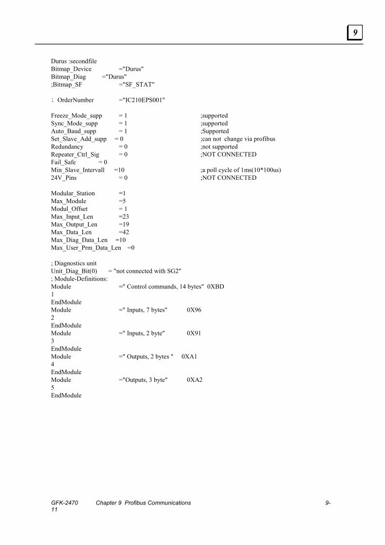
GFK-2470 Chapter 9 Profibus Communications 9-11
9
Durus :secondfile Bitmap_Device ="Durus" Bitmap_Diag ="Durus" ;Bitmap_SF ="SF_STAT" ; OrderNumber ="IC210EPS001" Freeze_Mode_supp = 1 ;supported Sync_Mode_supp = 1 ;supported Auto_Baud_supp = 1 ;Supported Set_Slave_Add_supp = 0 ;can not change via profibus Redundancy = 0 ;not supported Repeater_Ctrl_Sig = 0 ;NOT CONNECTED Fail_Safe = 0 Min_Slave_Intervall =10 ;a poll cycle of 1ms(10*100us) 24V_Pins = 0 ;NOT CONNECTED Modular_Station =1 Max_Module =5 Modul_Offset = 1 Max_Input_Len =23 Max_Output_Len =19 Max_Data_Len =42 Max_Diag_Data_Len =10 Max_User_Prm_Data_Len =0 ; Diagnostics unit Unit_Diag_Bit(0) = "not connected with SG2" ; Module-Definitions: Module =" Control commands, 14 bytes" 0XBD 1 EndModule Module =" Inputs, 7 bytes" 0X96 2 EndModule Module =" Inputs, 2 byte" 0X91 3 EndModule Module =" Outputs, 2 bytes " 0XA1 4 EndModule Module ="Outputs, 3 byte" 0XA2 5 EndModule
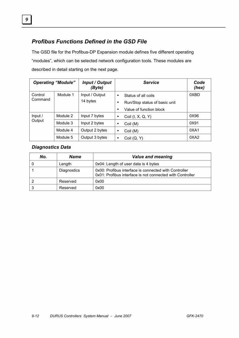
9-12 DURUS Controllers System Manual – June 2007 GFK-2470
9
Profibus Functions Defined in the GSD File
The GSD file for the Profibus-DP Expansion module defines five different operating
“modules”, which can be selected network configuration tools. These modules are
described in detail starting on the next page.
Operating “Module” Input / Output (Byte)
Service Code (hex)
Control Command
Module 1 Input / Output 14 bytes
▪ Status of all coils
▪ Run/Stop status of basic unit
▪ Value of function block
0XBD
Module 2 Input 7 bytes ▪ Coil (I, X, Q, Y) 0X96
Module 3 Input 2 bytes ▪ Coil (M) 0X91
Module 4 Output 2 bytes ▪ Coil (M) 0XA1
Input / Output
Module 5 Output 3 bytes ▪ Coil (Q, Y) 0XA2
Diagnostics Data
No. Name Value and meaning 0 Length 0x04: Length of user data is 4 bytes 1 Diagnostics 0x00: Profibus interface is connected with Controller
0x01: Profibus interface is not connected with Controller 2 Reserved 0x00 3 Reserved 0x00

GFK-2470 Chapter 9 Profibus Communications 9-13
9
Reading and Writing Durus Controller Data
By selecting input and output “modules” in the network configuration, the Profibus-DP
Master can read or write Durus Controller data. See the bit definitions at the bottom of the
page.
Input Module 2 reads 7 bytes of data in the I (input) X (expansion input), Q (output), and
Y (expansion output) tables:
Byte Meaning Value 0 COIL (I_L) TABLE: COIL _I 1 COIL (I_H) TABLE: COIL _I 2 COIL (X_L) TABLE: COIL_X 3 COIL (X_H) TABLE: COIL_X 4 COIL (Q) TABLE: COIL_Q 5 COIL (Y_L) TABLE: COIL_Y 6 COIL (Y_H) TABLE: COIL_Y
Input Module 3 reads 2 bytes of data in the M (internal coils) table:
Byte Meaning Value 0 COIL (M_L) TABLE: COIL _M 1 COIL (M_H) TABLE: COIL _M
Output Module 4 sets or clears bits in 2 bytes of data in the M (internal coils) table:
Byte Meaning Value 0 COIL (M_L) TABLE: COIL _M 1 COIL (M_H) TABLE: COIL _M
Output Module 5: sets or clears bits in 3 bytes of data in the Q (output) and Y (expansion
output) tables.
Byte Meaning Value 0 COIL (Q) TABLE: COIL_Q 1 COIL (Y_L) TABLE: COIL_Y 2 COIL (Y_H) TABLE: COIL_Y
Bit Definitions Within each type of coils table (I, X, Q, Y, M), the bits assignments are:
Byte1 Byte0 Bits Bits
7 6 5 4 3 2 1 0 7 6 5 4 3 2 1 0 0 0 0 0 0 0 0 0 8 7 6 5 4 3 2 1 Coils Q 0 0 0 0 12 11 10 9 8 7 6 5 4 3 2 1 Coils I, X, Y 16 15 14 13 12 11 10 9 8 7 6 5 4 3 2 1 Coils M
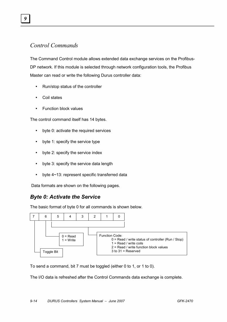
9-14 DURUS Controllers System Manual – June 2007 GFK-2470
9
Control Commands
The Command Control module allows extended data exchange services on the Profibus-
DP network. If this module is selected through network configuration tools, the Profibus
Master can read or write the following Durus controller data:
▪ Run/stop status of the controller
▪ Coil states
▪ Function block values
The control command itself has 14 bytes.
▪ byte 0: activate the required services
▪ byte 1: specify the service type
▪ byte 2: specify the service index
▪ byte 3: specify the service data length
▪ byte 4~13: represent specific transferred data
Data formats are shown on the following pages.
Byte 0: Activate the Service
The basic format of byte 0 for all commands is shown below.
7 6 5 4 3 2 1 0
Function Code: 0 = Read / write status of controller (Run / Stop) 1 = Read / write coils 2 = Read / write function block values 3 to 31 = Reserved
0 = Read 1 = Write
Toggle Bit
To send a command, bit 7 must be toggled (either 0 to 1, or 1 to 0).
The I/O data is refreshed after the Control Commands data exchange is complete.
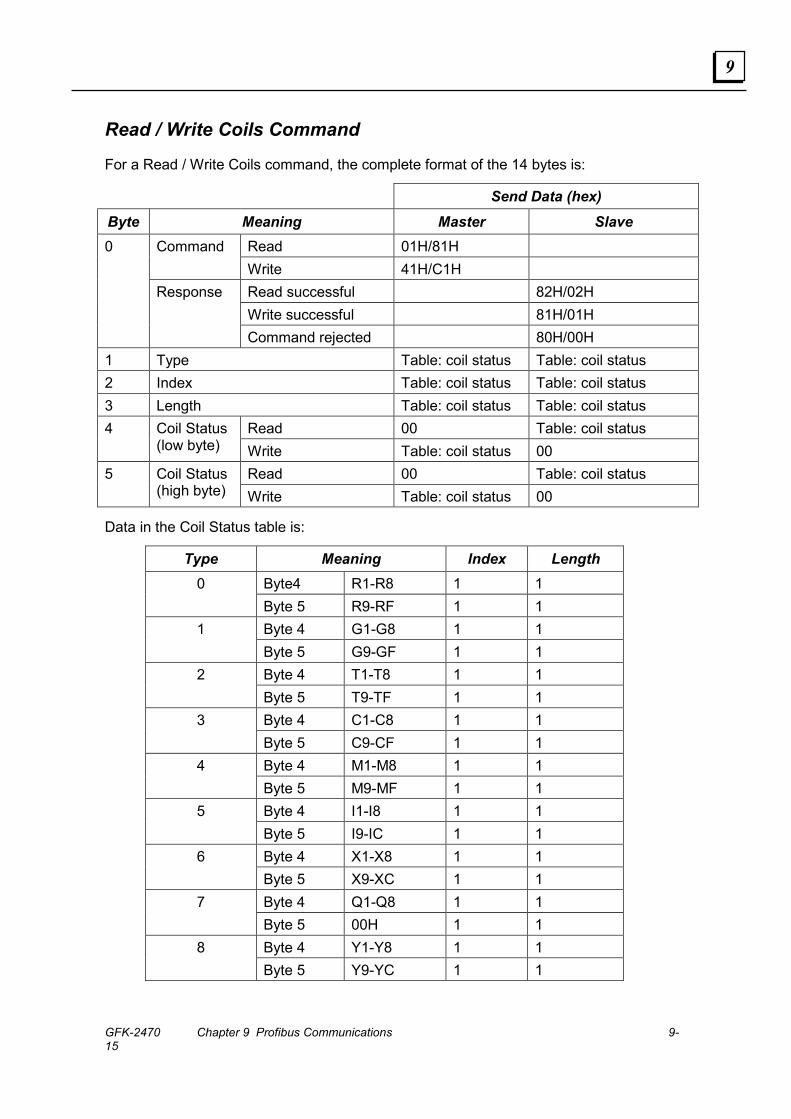
GFK-2470 Chapter 9 Profibus Communications 9-15
9
Read / Write Coils Command
For a Read / Write Coils command, the complete format of the 14 bytes is:
Send Data (hex) Byte Meaning Master Slave
Read 01H/81H Command Write 41H/C1H Read successful 82H/02H Write successful 81H/01H
0
Response
Command rejected 80H/00H 1 Type Table: coil status Table: coil status 2 Index Table: coil status Table: coil status 3 Length Table: coil status Table: coil status
Read 00 Table: coil status 4 Coil Status (low byte) Write Table: coil status 00
Read 00 Table: coil status 5 Coil Status (high byte) Write Table: coil status 00
Data in the Coil Status table is:
Type Meaning Index Length Byte4 R1-R8 1 1 0 Byte 5 R9-RF 1 1 Byte 4 G1-G8 1 1 1 Byte 5 G9-GF 1 1 Byte 4 T1-T8 1 1 2 Byte 5 T9-TF 1 1 Byte 4 C1-C8 1 1 3 Byte 5 C9-CF 1 1 Byte 4 M1-M8 1 1 4 Byte 5 M9-MF 1 1 Byte 4 I1-I8 1 1 5 Byte 5 I9-IC 1 1 Byte 4 X1-X8 1 1 6 Byte 5 X9-XC 1 1 Byte 4 Q1-Q8 1 1 7 Byte 5 00H 1 1 Byte 4 Y1-Y8 1 1 8 Byte 5 Y9-YC 1 1
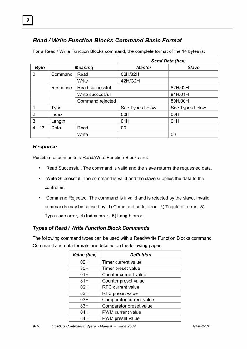
9-16 DURUS Controllers System Manual – June 2007 GFK-2470
9
Read / Write Function Blocks Command Basic Format
For a Read / Write Function Blocks command, the complete format of the 14 bytes is:
Send Data (hex) Byte Meaning Master Slave
Read 02H/82H Command Write 42H/C2H Read successful 82H/02H Write successful 81H/01H
0
Response
Command rejected 80H/00H 1 Type See Types below See Types below 2 Index 00H 00H 3 Length 01H 01H
Read 00 4 - 13 Data Write 00
Response
Possible responses to a Read/Write Function Blocks are:
▪ Read Successful. The command is valid and the slave returns the requested data.
▪ Write Successful. The command is valid and the slave supplies the data to the
controller.
▪ Command Rejected. The command is invalid and is rejected by the slave. Invalid
commands may be caused by: 1) Command code error, 2) Toggle bit error, 3)
Type code error, 4) Index error, 5) Length error.
Types of Read / Write Function Block Commands
The following command types can be used with a Read/Write Function Blocks command. Command and data formats are detailed on the following pages.
Value (hex) Definition 00H Timer current value 80H Timer preset value 01H Counter current value 81H Counter preset value 02H RTC current value 82H RTC preset value 03H Comparator current value 83H Comparator preset value 04H PWM current value 84H PWM preset value
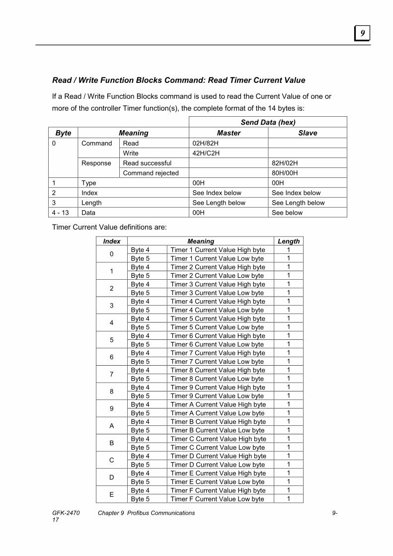
GFK-2470 Chapter 9 Profibus Communications 9-17
9
Read / Write Function Blocks Command: Read Timer Current Value
If a Read / Write Function Blocks command is used to read the Current Value of one or more of the controller Timer function(s), the complete format of the 14 bytes is:
Send Data (hex) Byte Meaning Master Slave
Read 02H/82H Command Write 42H/C2H Read successful 82H/02H
0
Response Command rejected 80H/00H
1 Type 00H 00H 2 Index See Index below See Index below 3 Length See Length below See Length below 4 - 13 Data 00H See below
Timer Current Value definitions are:
Index Meaning Length Byte 4 Timer 1 Current Value High byte 1 0 Byte 5 Timer 1 Current Value Low byte 1 Byte 4 Timer 2 Current Value High byte 1
1 Byte 5 Timer 2 Current Value Low byte 1 Byte 4 Timer 3 Current Value High byte 1
2 Byte 5 Timer 3 Current Value Low byte 1 Byte 4 Timer 4 Current Value High byte 1
3 Byte 5 Timer 4 Current Value Low byte 1 Byte 4 Timer 5 Current Value High byte 1
4 Byte 5 Timer 5 Current Value Low byte 1 Byte 4 Timer 6 Current Value High byte 1
5 Byte 5 Timer 6 Current Value Low byte 1 Byte 4 Timer 7 Current Value High byte 1
6 Byte 5 Timer 7 Current Value Low byte 1 Byte 4 Timer 8 Current Value High byte 1
7 Byte 5 Timer 8 Current Value Low byte 1 Byte 4 Timer 9 Current Value High byte 1
8 Byte 5 Timer 9 Current Value Low byte 1 Byte 4 Timer A Current Value High byte 1
9 Byte 5 Timer A Current Value Low byte 1 Byte 4 Timer B Current Value High byte 1
A Byte 5 Timer B Current Value Low byte 1 Byte 4 Timer C Current Value High byte 1
B Byte 5 Timer C Current Value Low byte 1 Byte 4 Timer D Current Value High byte 1
C Byte 5 Timer D Current Value Low byte 1 Byte 4 Timer E Current Value High byte 1
D Byte 5 Timer E Current Value Low byte 1 Byte 4 Timer F Current Value High byte 1
E Byte 5 Timer F Current Value Low byte 1
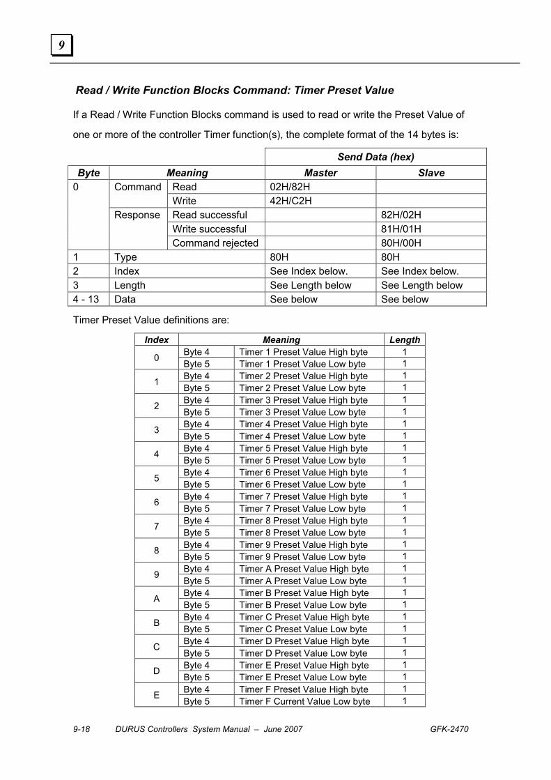
9-18 DURUS Controllers System Manual – June 2007 GFK-2470
9
Read / Write Function Blocks Command: Timer Preset Value
If a Read / Write Function Blocks command is used to read or write the Preset Value of
one or more of the controller Timer function(s), the complete format of the 14 bytes is:
Send Data (hex) Byte Meaning Master Slave
Read 02H/82H Command Write 42H/C2H Read successful 82H/02H Write successful 81H/01H
0
Response
Command rejected 80H/00H 1 Type 80H 80H 2 Index See Index below. See Index below. 3 Length See Length below See Length below 4 - 13 Data See below See below
Timer Preset Value definitions are:
Index Meaning Length Byte 4 Timer 1 Preset Value High byte 1 0 Byte 5 Timer 1 Preset Value Low byte 1 Byte 4 Timer 2 Preset Value High byte 1
1 Byte 5 Timer 2 Preset Value Low byte 1 Byte 4 Timer 3 Preset Value High byte 1
2 Byte 5 Timer 3 Preset Value Low byte 1 Byte 4 Timer 4 Preset Value High byte 1
3 Byte 5 Timer 4 Preset Value Low byte 1 Byte 4 Timer 5 Preset Value High byte 1
4 Byte 5 Timer 5 Preset Value Low byte 1 Byte 4 Timer 6 Preset Value High byte 1
5 Byte 5 Timer 6 Preset Value Low byte 1 Byte 4 Timer 7 Preset Value High byte 1
6 Byte 5 Timer 7 Preset Value Low byte 1 Byte 4 Timer 8 Preset Value High byte 1
7 Byte 5 Timer 8 Preset Value Low byte 1 Byte 4 Timer 9 Preset Value High byte 1
8 Byte 5 Timer 9 Preset Value Low byte 1 Byte 4 Timer A Preset Value High byte 1
9 Byte 5 Timer A Preset Value Low byte 1 Byte 4 Timer B Preset Value High byte 1
A Byte 5 Timer B Preset Value Low byte 1 Byte 4 Timer C Preset Value High byte 1
B Byte 5 Timer C Preset Value Low byte 1 Byte 4 Timer D Preset Value High byte 1
C Byte 5 Timer D Preset Value Low byte 1 Byte 4 Timer E Preset Value High byte 1
D Byte 5 Timer E Preset Value Low byte 1 Byte 4 Timer F Preset Value High byte 1
E Byte 5 Timer F Current Value Low byte 1
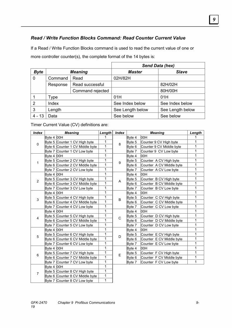
GFK-2470 Chapter 9 Profibus Communications 9-19
9
Read / Write Function Blocks Command: Read Counter Current Value
If a Read / Write Function Blocks command is used to read the current value of one or
more controller counter(s), the complete format of the 14 bytes is:
Send Data (hex) Byte Meaning Master Slave
Command Read 02H/82H Read successful 82H/02H
0 Response
Command rejected 80H/00H 1 Type 01H 01H 2 Index See Index below See Index below 3 Length See Length below See Length below 4 - 13 Data See below See below
Timer Current Value (CV) definitions are:
Index Meaning Length Index Meaning Length Byte 4 00H 1 Byte 4 00H 1 Byte 5 Counter 1 CV High byte 1 Byte 5 Counter 9 CV High byte 1 Byte 6 Counter 1 CV Middle byte 1 Byte 6 Counter 9 CV Middle byte 1 0
Byte 7 Counter 1 CV Low byte 1
8
Byte 7 Counter 9 CV Low byte 1 Byte 4 00H 1 Byte 4 00H 1 Byte 5 Counter 2 CV High byte 1 Byte 5 Counter A CV High byte 1 Byte 6 Counter 2 CV Middle byte 1 Byte 6 Counter A CV Middle byte 1 1
Byte 7 Counter 2 CV Low byte 1
9
Byte 7 Counter A CV Low byte 1 Byte 4 00H 1 Byte 4 00H 1 Byte 5 Counter 3 CV High byte 1 Byte 5 Counter B CV High byte 1 Byte 6 Counter 3 CV Middle byte 1 Byte 6 Counter B CV Middle byte 1 2
Byte 7 Counter 3 CV Low byte 1
A
Byte 7 Counter B CV Low byte 1 Byte 4 00H 1 Byte 4 00H 1 Byte 5 Counter 4 CV High byte 1 Byte 5 Counter C CV High byte 1 Byte 6 Counter 4 CV Middle byte 1 Byte 6 Counter C CV Middle byte 1 3
Byte 7 Counter 4 CV Low byte 1
B
Byte 7 Counter C CV Low byte 1 Byte 4 00H 1 Byte 4 00H 1 Byte 5 Counter 5 CV High byte 1 Byte 5 Counter D CV High byte 1 Byte 6 Counter 5 CV Middle byte 1 Byte 6 Counter D CV Middle byte 1 4
Byte 7 Counter 5 CV Low byte 1
C
Byte 7 Counter D CV Low byte 1 Byte 4 00H 1 Byte 4 00H 1 Byte 5 Counter 6 CV High byte 1 Byte 5 Counter E CV High byte 1 Byte 6 Counter 6 CV Middle byte 1 Byte 6 Counter E CV Middle byte 1 5
Byte 7 Counter 6 CV Low byte 1
D
Byte 7 Counter E CV Low byte 1 Byte 4 00H 1 Byte 4 00H 1 Byte 5 Counter 7 CV High byte 1 Byte 5 Counter F CV High byte 1 Byte 6 Counter 7 CV Middle byte 1 Byte 6 Counter F CV Middle byte 1 6
Byte 7 Counter 7 CV Low byte 1
E
Byte 7 Counter F CV Low byte 1 Byte 4 00H 1 Byte 5 Counter 8 CV High byte 1 Byte 6 Counter 8 CV Middle byte 1 7
Byte 7 Counter 8 CV Low byte 1
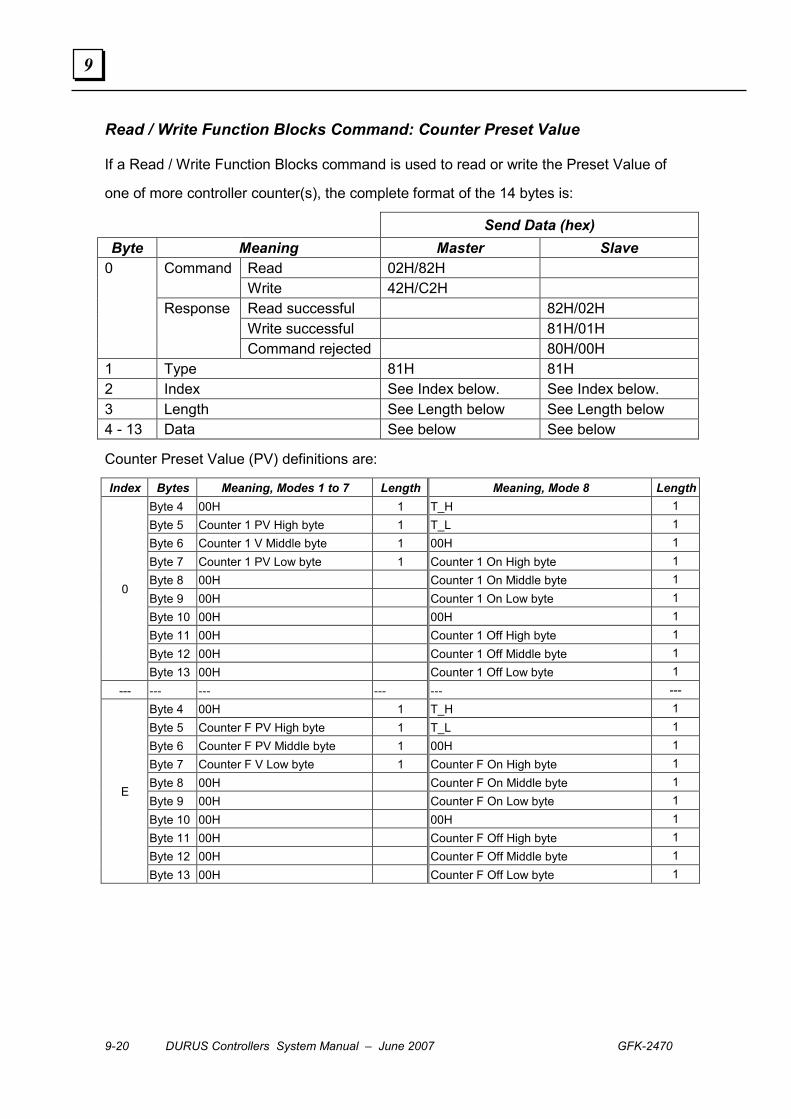
9-20 DURUS Controllers System Manual – June 2007 GFK-2470
9
Read / Write Function Blocks Command: Counter Preset Value
If a Read / Write Function Blocks command is used to read or write the Preset Value of
one of more controller counter(s), the complete format of the 14 bytes is:
Send Data (hex) Byte Meaning Master Slave
Read 02H/82H Command Write 42H/C2H Read successful 82H/02H Write successful 81H/01H
0
Response
Command rejected 80H/00H 1 Type 81H 81H 2 Index See Index below. See Index below. 3 Length See Length below See Length below 4 - 13 Data See below See below
Counter Preset Value (PV) definitions are:
Index Bytes Meaning, Modes 1 to 7 Length Meaning, Mode 8 LengthByte 4 00H 1 T_H 1 Byte 5 Counter 1 PV High byte 1 T_L 1 Byte 6 Counter 1 V Middle byte 1 00H 1 Byte 7 Counter 1 PV Low byte 1 Counter 1 On High byte 1 Byte 8 00H Counter 1 On Middle byte 1 Byte 9 00H Counter 1 On Low byte 1 Byte 10 00H 00H 1 Byte 11 00H Counter 1 Off High byte 1 Byte 12 00H Counter 1 Off Middle byte 1
0
Byte 13 00H Counter 1 Off Low byte 1 --- --- --- --- --- ---
Byte 4 00H 1 T_H 1 Byte 5 Counter F PV High byte 1 T_L 1 Byte 6 Counter F PV Middle byte 1 00H 1 Byte 7 Counter F V Low byte 1 Counter F On High byte 1 Byte 8 00H Counter F On Middle byte 1 Byte 9 00H Counter F On Low byte 1 Byte 10 00H 00H 1 Byte 11 00H Counter F Off High byte 1 Byte 12 00H Counter F Off Middle byte 1
E
Byte 13 00H Counter F Off Low byte 1

GFK-2470 Chapter 9 Profibus Communications 9-21
9
Read / Write Function Blocks Command: Read / Write Real Time Clock Current Value
If a Read / Write Function Blocks command is used to read or write the Current Value of
one or more of the controller Real Time Clock(s), the complete format of the 14 bytes is:
Send Data (hex) Byte Meaning Master Slave
Read 02H/82H Command Write 42H/C2H Read successful 82H/02H Write successful 81H/01H
0
Response
Command rejected 80H/00H 1 Type 02H 02H 2 Index See Index below See Index below 3 Length See Length below See Length below 4 - 13 Data 00H See below
Real Time Clock byte definitions are:
Index Meaning Length Byte 4 Year 1 Byte 5 Month 1 Byte 6 Day 1 Byte 7 Week 1 Byte 8 Hour 1 Byte 9 Minute 1
0
Byte 10 Second 1

9-22 DURUS Controllers System Manual – June 2007 GFK-2470
9
Read / Write Function Blocks Command: Read / Write Real Time Clock Preset Value
If a Read / Write Function Blocks command is used to read or write the Preset Value of
one or more Real Time Clock function(s), the complete format of the 14 bytes is:
Send Data (hex) Byte Meaning Master Slave
Read 02H/82H Command Write 42H/C2H Read successful 82H/02H Write successful 81H/01H
0
Response
Command rejected 80H/00H 1 Type 82H 82H 2 Index See Index below. See Index below. 3 Length See Length below See Length below 4 - 13 Data See below See below
Real Time Clock Preset Value definitions are:
Index Bytes Meaning, Modes 1, 2 Length Meaning, Mode 3 LengthByte 4 R1: On Week 1 R1: On Year 1 Byte 5 R1: Off Week 1 R1: Off Year 1 Byte 6 R1: On Hour 1 R1: On Month 1 Byte 7 R1: Off Hour 1 R1: Off Month 1 Byte 8 R1: On Minute 1 R1: On Day 1
0
Byte 9 R1: Off Minute 1 R1: Off Day 1 --- --- --- --- --- ---
Byte 4 RF: On Week 1 R1: On Year 1 Byte 5 RF: Off Week 1 R1: Off Year 1 Byte 6 RF: On Hour 1 R1: On Month 1 Byte 7 RF: Off Hour 1 R1: Off Month 1 Byte 8 RF: On Minute 1 R1: On Day 1
E
Byte 9 RF: Off Minute 1 R1: Off Day 1

GFK-2470 Chapter 9 Profibus Communications 9-23
9
Read / Write Function Blocks Command: Read Comparator Current Value
If a Read / Write Function Blocks command is used to read the Current Value of one or
more Analog Comparator function(s), the complete format of the 14 bytes is:
Send Data (hex) Byte Meaning Master Slave
Read 02H/82H Command Write 42H/C2H Read successful 82H/02H
0
Response Command rejected 80H/00H
1 Type 03H 03H 2 Index See Index below See Index below 3 Length See Length below See Length below 4 - 13 Data 00H See below
Comparator definitions are:
Index Meaning Length Byte 4 A1 Comparator Value, High 1 Byte 5 A1 Comparator Value, Low 1 Byte 6 A2 Comparator Value, High 1 Byte 7 A2 Comparator Value, Low 1 Byte 8 A3 Comparator Value, High 1 Byte 9 A3 Comparator Value, Low 1 Byte 10 A4 Comparator Value, High 1
0
Byte 10 A4 Comparator Value, Low 1 Byte 4 A51 Comparator Value, High 1 Byte 5 A51 Comparator Value, Low 1 Byte 6 A6 Comparator Value, High 1 Byte 7 A6 Comparator Value, Low 1 Byte 8 A7 Comparator Value, High 1 Byte 9 A7 Comparator Value, Low 1 Byte 10 A8 Comparator Value, High 1
1
Byte 10 A8 Comparator Value, Low 1

9-24 DURUS Controllers System Manual – June 2007 GFK-2470
9
Read / Write Function Blocks Command: Read / Write Comparator Preset Value
If a Read / Write Function Blocks command is used to read or write the Preset Value of one or more Analog Comparator function(s), the complete format of the 14 bytes is:
Send Data (hex) Byte Meaning Master Slave
Read 02H/82H Command Write 42H/C2H Read successful 82H/02H Write successful 81H/01H
0
Response
Command rejected 80H/00H 1 Type 83H 83H 2 Index See Index below. See Index below. 3 Length See Length below See Length below 4 - 13 Data See below See below
Comparator Preset Value definitions are:
Index Meaning Length Byte 4 G1 Preset Value High byte 1 0 Byte 5 G1 Preset Value Low byte 1 Byte 4 G2 Preset Value High byte 1 1 Byte 5 G2 Preset Value Low byte 1 Byte 4 G 3 Preset Value High byte 1 2 Byte 5 G 3 Preset Value Low byte 1 Byte 4 G 4 Preset Value High byte 1 3 Byte 5 G 4 Preset Value Low byte 1 Byte 4 G 5 Preset Value High byte 1 4 Byte 5 G 5 Preset Value Low byte 1 Byte 4 G 6 Preset Value High byte 1 5 Byte 5 G 6 Preset Value Low byte 1 Byte 4 G 7 Preset Value High byte 1 6 Byte 5 G 7 Preset Value Low byte 1 Byte 4 G 8 Preset Value High byte 1 7 Byte 5 G 8 Preset Value Low byte 1 Byte 4 G 9 Preset Value High byte 1 8 Byte 5 G 9 Preset Value Low byte 1 Byte 4 G A Preset Value High byte 1 9 Byte 5 G A Preset Value Low byte 1 Byte 4 G B Preset Value High byte 1 A Byte 5 G B Preset Value Low byte 1 Byte 4 G C Preset Value High byte 1 B Byte 5 G C Preset Value Low byte 1 Byte 4 G D Preset Value High byte 1 C Byte 5 G D Preset Value Low byte 1 Byte 4 G E Preset Value High byte 1 D Byte 5 G E Preset Value Low byte 1 Byte 4 G F Preset Value High byte 1 E Byte 5 G F Current Value Low byte 1
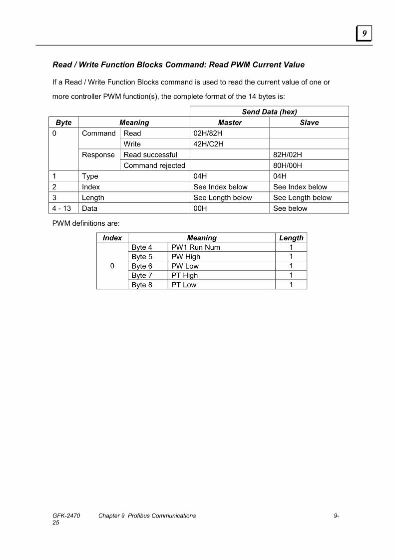
GFK-2470 Chapter 9 Profibus Communications 9-25
9
Read / Write Function Blocks Command: Read PWM Current Value
If a Read / Write Function Blocks command is used to read the current value of one or
more controller PWM function(s), the complete format of the 14 bytes is:
Send Data (hex) Byte Meaning Master Slave
Read 02H/82H Command Write 42H/C2H Read successful 82H/02H
0
Response Command rejected 80H/00H
1 Type 04H 04H 2 Index See Index below See Index below 3 Length See Length below See Length below 4 - 13 Data 00H See below
PWM definitions are:
Index Meaning Length Byte 4 PW1 Run Num 1 Byte 5 PW High 1 Byte 6 PW Low 1 Byte 7 PT High 1
0
Byte 8 PT Low 1
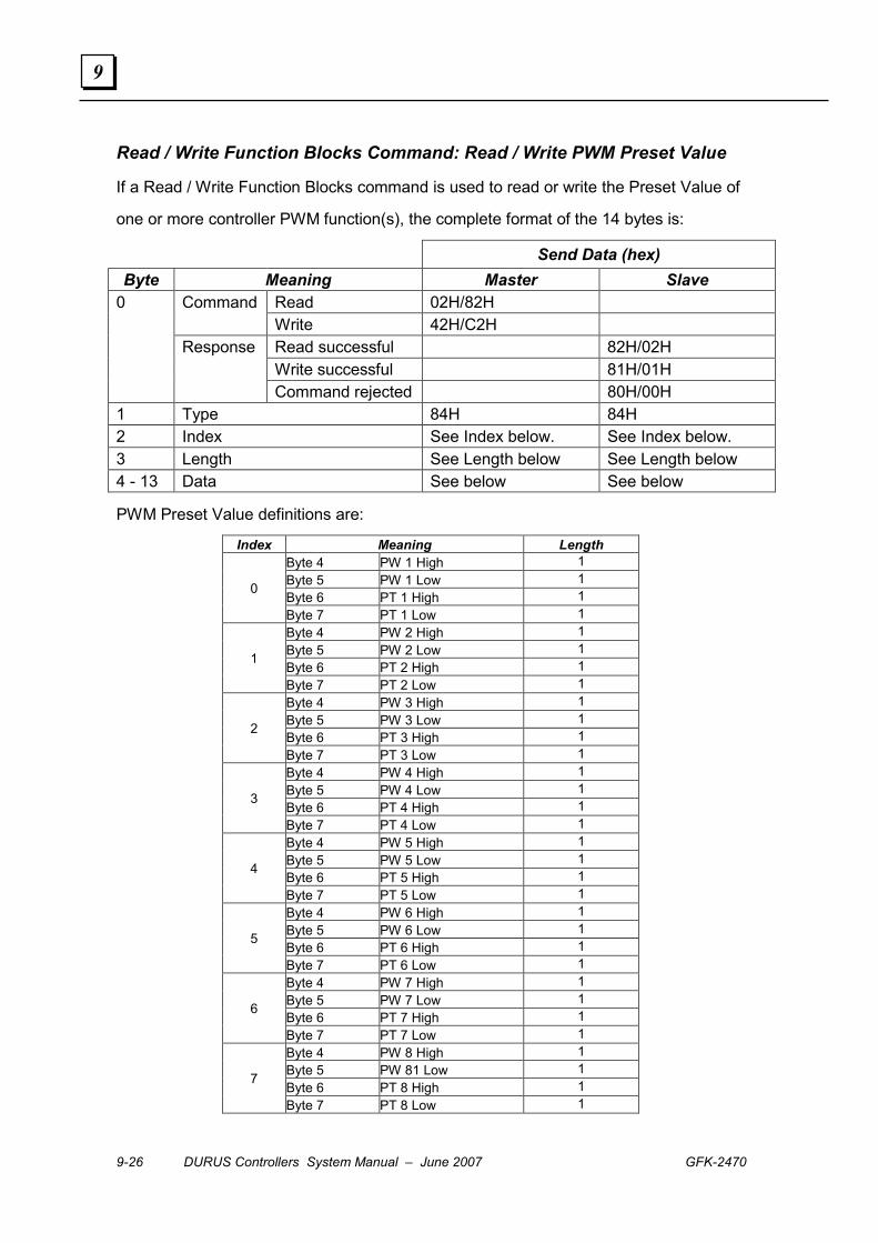
9-26 DURUS Controllers System Manual – June 2007 GFK-2470
9
Read / Write Function Blocks Command: Read / Write PWM Preset Value
If a Read / Write Function Blocks command is used to read or write the Preset Value of
one or more controller PWM function(s), the complete format of the 14 bytes is:
Send Data (hex) Byte Meaning Master Slave
Read 02H/82H Command Write 42H/C2H Read successful 82H/02H Write successful 81H/01H
0
Response
Command rejected 80H/00H 1 Type 84H 84H 2 Index See Index below. See Index below. 3 Length See Length below See Length below 4 - 13 Data See below See below
PWM Preset Value definitions are:
Index Meaning Length Byte 4 PW 1 High 1 Byte 5 PW 1 Low 1 Byte 6 PT 1 High 1 0
Byte 7 PT 1 Low 1 Byte 4 PW 2 High 1 Byte 5 PW 2 Low 1 Byte 6 PT 2 High 1 1
Byte 7 PT 2 Low 1 Byte 4 PW 3 High 1 Byte 5 PW 3 Low 1 Byte 6 PT 3 High 1 2
Byte 7 PT 3 Low 1 Byte 4 PW 4 High 1 Byte 5 PW 4 Low 1 Byte 6 PT 4 High 1 3
Byte 7 PT 4 Low 1 Byte 4 PW 5 High 1 Byte 5 PW 5 Low 1 Byte 6 PT 5 High 1 4
Byte 7 PT 5 Low 1 Byte 4 PW 6 High 1 Byte 5 PW 6 Low 1 Byte 6 PT 6 High 1 5
Byte 7 PT 6 Low 1 Byte 4 PW 7 High 1 Byte 5 PW 7 Low 1 Byte 6 PT 7 High 1 6
Byte 7 PT 7 Low 1 Byte 4 PW 8 High 1 Byte 5 PW 81 Low 1 Byte 6 PT 8 High 1 7
Byte 7 PT 8 Low 1
GFK-2470 10-1
DeviceNet Communications
This chapter describes the DeviceNet features that can be incorporated into a Durus
controller system by including a DeviceNet Slave Communications Expansion Module,
24VDC (IC210EDS001).
▪ Overview
▪ Device Profile
▪ I/O Assembly Data Definitions
▪ DeviceNet Information
▪ DeviceNet Object Class Definitions
Chapter
10
10-2 DURUS Controllers System Manual – June 2007 GFK-2470
10
Overview
The DeviceNet Slave Communications Expansion Module (IC210EDS001) operates as a DeviceNet Group II Only Slave device, interfacing the Durus controller to a DeviceNet communications bus. If a DeviceNet Communications Expansion Module is installed in the controller, it must be the only communications module present.
Network Parameters ▪ Group 2 Slave only
▪ Baud rate and MAC ID set by a 8-bit DIP switch. Not set from network.
▪ Standard DeviceNet Baud rates: 125K, 250K, 500K;
▪ Network MAC ID: 0 to 63;
▪ Powered by the network.
DeviceNet Features of the Module ▪ Predefined master slave connection
▪ Predefined explicit message connection
▪ Predefined poll IO message connection
▪ Explicit and I/O message fragment
▪ Duplicate MAC ID check
▪ UCMM incapable device
The following are not supported:
▪ Bit-strobe I/O message
▪ Change of state and cyclic I/O message
▪ Device communication faulted message
▪ Device heartbeat message
▪ Device shutdown message
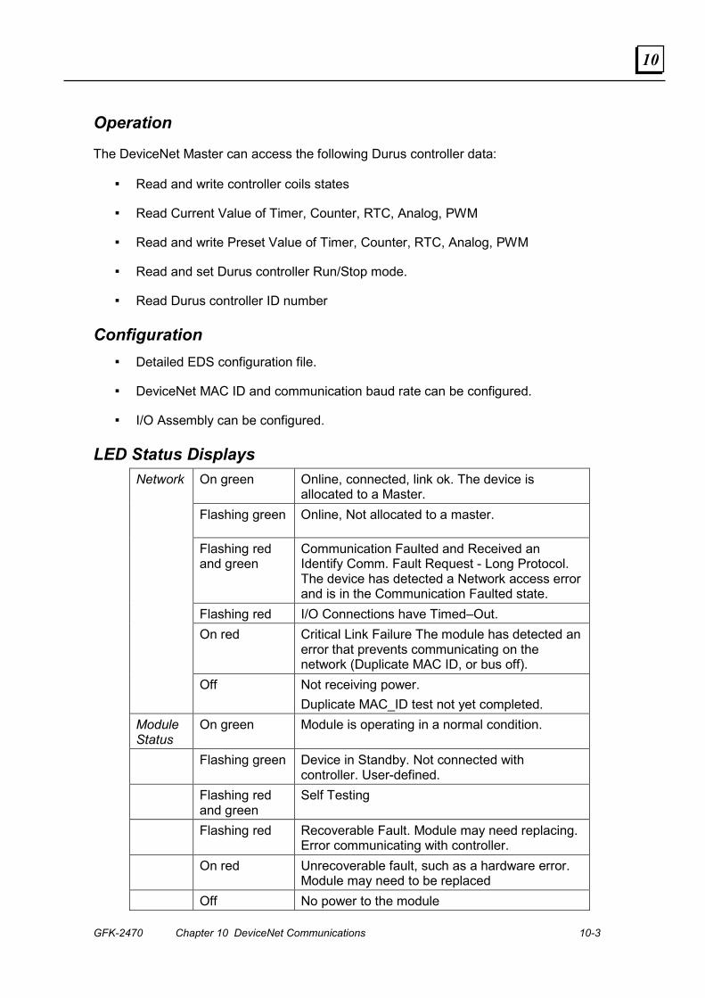
GFK-2470 Chapter 10 DeviceNet Communications 10-3
10
Operation
The DeviceNet Master can access the following Durus controller data:
▪ Read and write controller coils states
▪ Read Current Value of Timer, Counter, RTC, Analog, PWM
▪ Read and write Preset Value of Timer, Counter, RTC, Analog, PWM
▪ Read and set Durus controller Run/Stop mode.
▪ Read Durus controller ID number
Configuration ▪ Detailed EDS configuration file.
▪ DeviceNet MAC ID and communication baud rate can be configured.
▪ I/O Assembly can be configured.
LED Status Displays On green Online, connected, link ok. The device is
allocated to a Master. Flashing green Online, Not allocated to a master.
Flashing red and green
Communication Faulted and Received an Identify Comm. Fault Request - Long Protocol. The device has detected a Network access error and is in the Communication Faulted state.
Flashing red I/O Connections have Timed–Out. On red Critical Link Failure The module has detected an
error that prevents communicating on the network (Duplicate MAC ID, or bus off).
Network
Off Not receiving power. Duplicate MAC_ID test not yet completed.
Module Status
On green Module is operating in a normal condition.
Flashing green Device in Standby. Not connected with controller. User-defined.
Flashing red and green
Self Testing
Flashing red Recoverable Fault. Module may need replacing. Error communicating with controller.
On red Unrecoverable fault, such as a hardware error. Module may need to be replaced
Off No power to the module
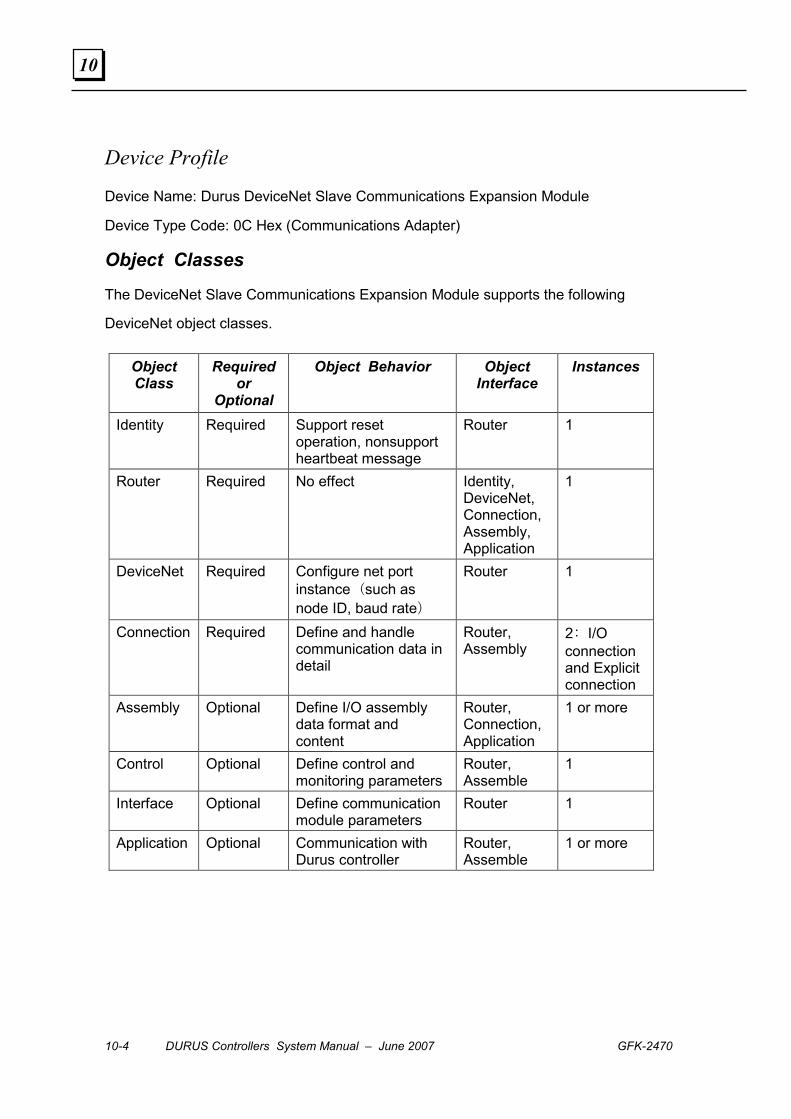
10-4 DURUS Controllers System Manual – June 2007 GFK-2470
10
Device Profile
Device Name: Durus DeviceNet Slave Communications Expansion Module
Device Type Code: 0C Hex (Communications Adapter)
Object Classes
The DeviceNet Slave Communications Expansion Module supports the following
DeviceNet object classes.
Object Class
Required or
Optional
Object Behavior Object Interface
Instances
Identity Required Support reset operation, nonsupport heartbeat message
Router 1
Router Required No effect Identity, DeviceNet, Connection, Assembly, Application
1
DeviceNet Required Configure net port instance (such as node ID, baud rate)
Router 1
Connection Required Define and handle communication data in detail
Router, Assembly
2: I/O connection and Explicit connection
Assembly Optional Define I/O assembly data format and content
Router, Connection, Application
1 or more
Control Optional Define control and monitoring parameters
Router, Assemble
1
Interface Optional Define communication module parameters
Router 1
Application Optional Communication with Durus controller
Router, Assemble
1 or more
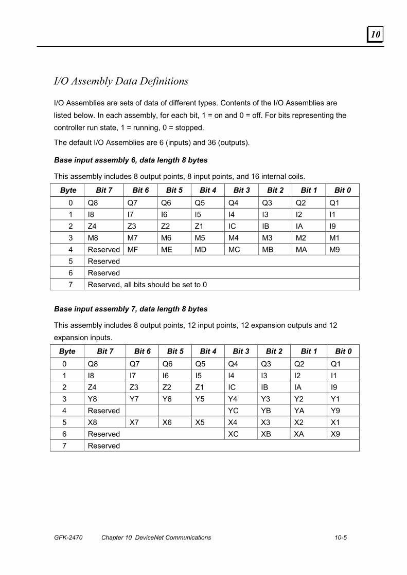
GFK-2470 Chapter 10 DeviceNet Communications 10-5
10
I/O Assembly Data Definitions
I/O Assemblies are sets of data of different types. Contents of the I/O Assemblies are listed below. In each assembly, for each bit, 1 = on and 0 = off. For bits representing the controller run state, 1 = running, 0 = stopped.
The default I/O Assemblies are 6 (inputs) and 36 (outputs).
Base input assembly 6, data length 8 bytes
This assembly includes 8 output points, 8 input points, and 16 internal coils.
Byte Bit 7 Bit 6 Bit 5 Bit 4 Bit 3 Bit 2 Bit 1 Bit 0 0 Q8 Q7 Q6 Q5 Q4 Q3 Q2 Q1 1 I8 I7 I6 I5 I4 I3 I2 I1 2 Z4 Z3 Z2 Z1 IC IB IA I9 3 M8 M7 M6 M5 M4 M3 M2 M1 4 Reserved MF ME MD MC MB MA M9 5 Reserved 6 Reserved 7 Reserved, all bits should be set to 0
Base input assembly 7, data length 8 bytes
This assembly includes 8 output points, 12 input points, 12 expansion outputs and 12 expansion inputs.
Byte Bit 7 Bit 6 Bit 5 Bit 4 Bit 3 Bit 2 Bit 1 Bit 0 0 Q8 Q7 Q6 Q5 Q4 Q3 Q2 Q1 1 I8 I7 I6 I5 I4 I3 I2 I1 2 Z4 Z3 Z2 Z1 IC IB IA I9 3 Y8 Y7 Y6 Y5 Y4 Y3 Y2 Y1 4 Reserved YC YB YA Y9 5 X8 X7 X6 X5 X4 X3 X2 X1 6 Reserved XC XB XA X9 7 Reserved
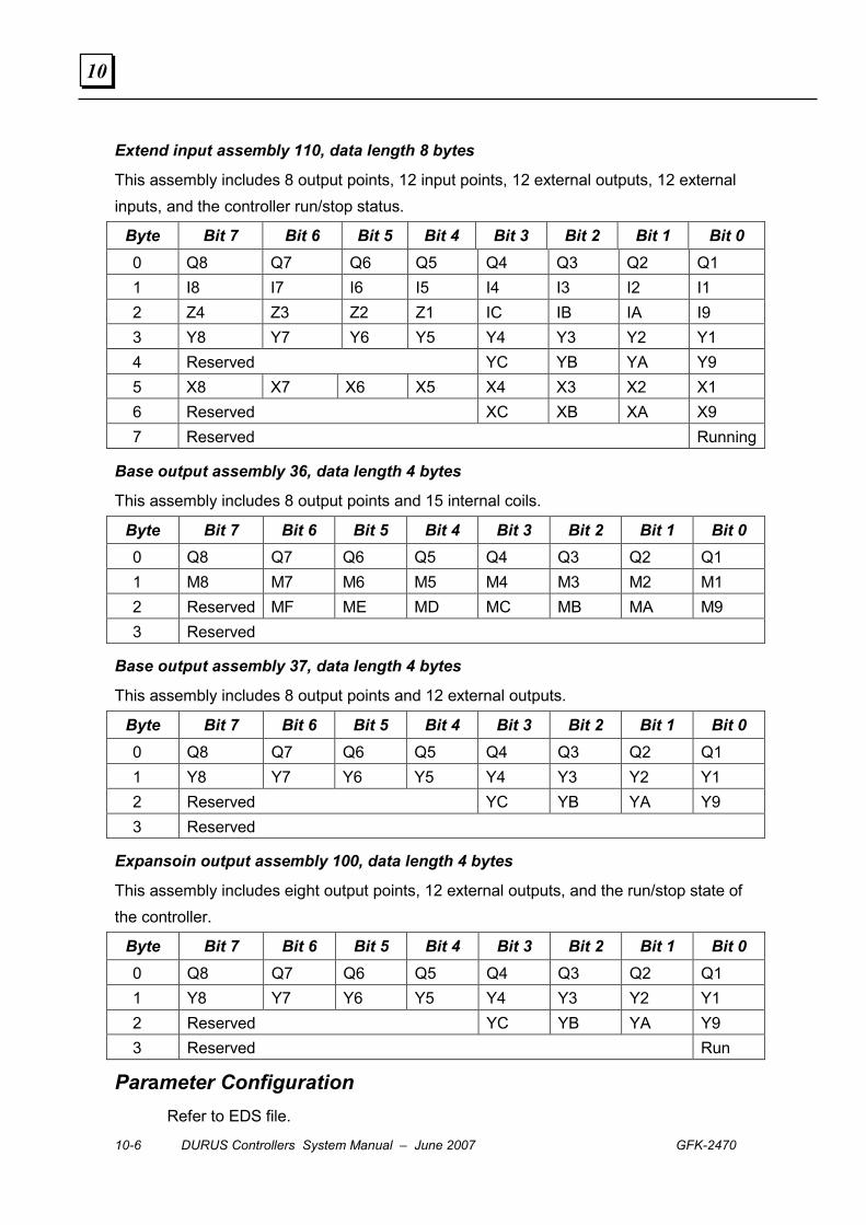
10-6 DURUS Controllers System Manual – June 2007 GFK-2470
10
Extend input assembly 110, data length 8 bytes
This assembly includes 8 output points, 12 input points, 12 external outputs, 12 external inputs, and the controller run/stop status.
Byte Bit 7 Bit 6 Bit 5 Bit 4 Bit 3 Bit 2 Bit 1 Bit 0 0 Q8 Q7 Q6 Q5 Q4 Q3 Q2 Q1 1 I8 I7 I6 I5 I4 I3 I2 I1 2 Z4 Z3 Z2 Z1 IC IB IA I9 3 Y8 Y7 Y6 Y5 Y4 Y3 Y2 Y1 4 Reserved YC YB YA Y9 5 X8 X7 X6 X5 X4 X3 X2 X1 6 Reserved XC XB XA X9 7 Reserved Running
Base output assembly 36, data length 4 bytes
This assembly includes 8 output points and 15 internal coils.
Byte Bit 7 Bit 6 Bit 5 Bit 4 Bit 3 Bit 2 Bit 1 Bit 0 0 Q8 Q7 Q6 Q5 Q4 Q3 Q2 Q1 1 M8 M7 M6 M5 M4 M3 M2 M1 2 Reserved MF ME MD MC MB MA M9 3 Reserved
Base output assembly 37, data length 4 bytes
This assembly includes 8 output points and 12 external outputs.
Byte Bit 7 Bit 6 Bit 5 Bit 4 Bit 3 Bit 2 Bit 1 Bit 0 0 Q8 Q7 Q6 Q5 Q4 Q3 Q2 Q1 1 Y8 Y7 Y6 Y5 Y4 Y3 Y2 Y1 2 Reserved YC YB YA Y9 3 Reserved
Expansoin output assembly 100, data length 4 bytes
This assembly includes eight output points, 12 external outputs, and the run/stop state of the controller.
Byte Bit 7 Bit 6 Bit 5 Bit 4 Bit 3 Bit 2 Bit 1 Bit 0 0 Q8 Q7 Q6 Q5 Q4 Q3 Q2 Q1 1 Y8 Y7 Y6 Y5 Y4 Y3 Y2 Y1 2 Reserved YC YB YA Y9 3 Reserved Run
Parameter Configuration Refer to EDS file.

GFK-2470 Chapter 10 DeviceNet Communications 10-7
10
DeviceNet Information
Message Types As a Group II slave device, the communication module supports the following message types:
Communication module consumed message type
CAN Identity Field Group2 Message Type Remark 10xxxxxx111 Duplicate MAC ID check
message 10xxxxxx110 Predefine master/slave
connection message 10xxxxxx101 Source poll IO request
message 10xxxxxx100 Source explicit request
message
xxxxxx is device MAC ID
DeviceNet Services As a Group II only slave device, the DeviceNet Expansion Communication module supports the following class services and instance services:
Service name Service code Reset 0x05 Get Attribute Single 0x0E Set Attribute Single 0x10 Allocate Master Slave Connection Set 0x4B Release Master Slave Connection Set 0x4C
DeviceNet Objects Class code Object class name Instance number
01hex Identity 1 02hex Router 1 03hex DeviceNet 1 04hex Assembly 6 05hex Connection 2 29hex Control 1 64hex Interface 1 65hex Durus expansion 1
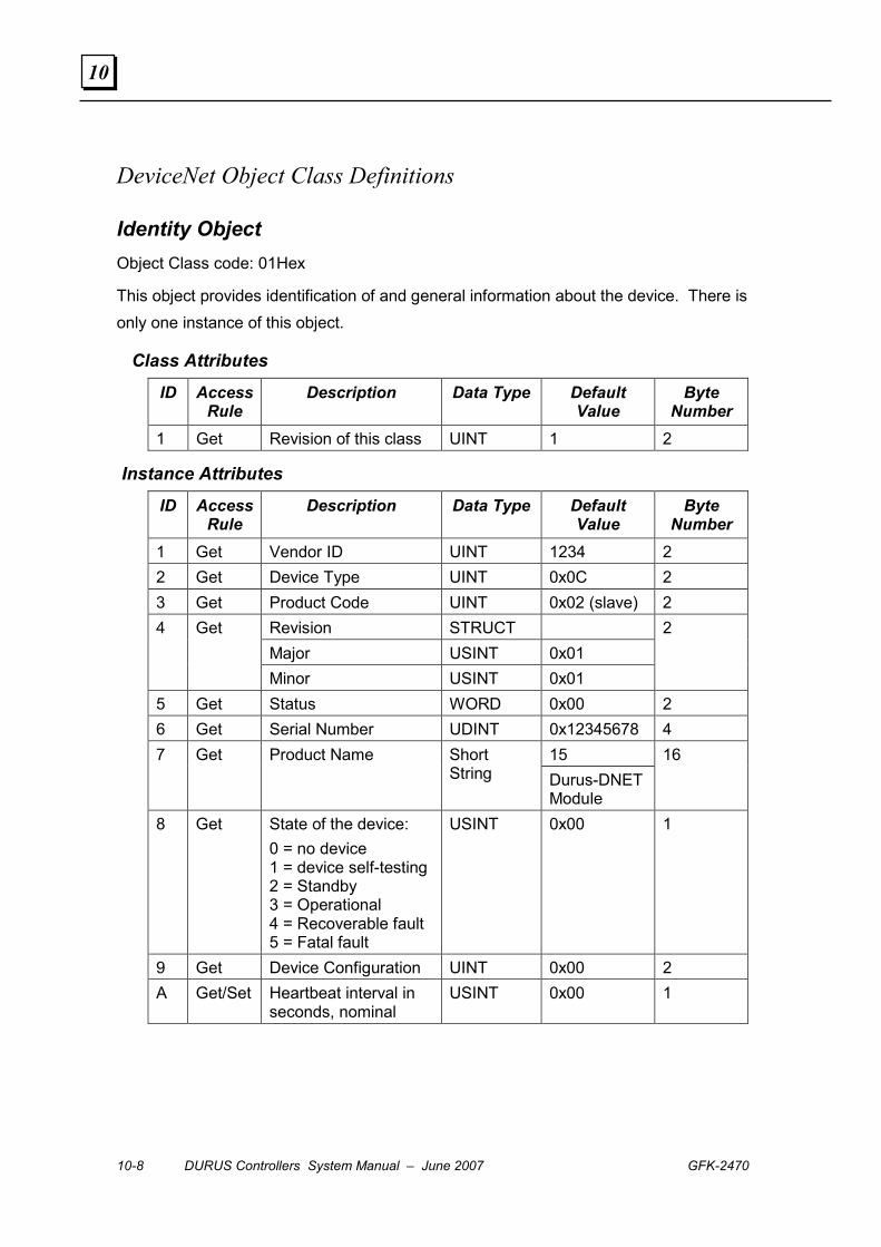
10-8 DURUS Controllers System Manual – June 2007 GFK-2470
10
DeviceNet Object Class Definitions
Identity Object Object Class code: 01Hex
This object provides identification of and general information about the device. There is only one instance of this object.
Class Attributes
ID Access Rule
Description Data Type Default Value
Byte Number
1 Get Revision of this class UINT 1 2
Instance Attributes
ID Access Rule
Description Data Type Default Value
Byte Number
1 Get Vendor ID UINT 1234 2 2 Get Device Type UINT 0x0C 2 3 Get Product Code UINT 0x02 (slave) 2
Revision STRUCT Major USINT 0x01
4 Get
Minor USINT 0x01
2
5 Get Status WORD 0x00 2 6 Get Serial Number UDINT 0x12345678 4
15 7 Get Product Name Short String Durus-DNET
Module
16
8 Get State of the device: 0 = no device 1 = device self-testing 2 = Standby 3 = Operational 4 = Recoverable fault 5 = Fatal fault
USINT 0x00 1
9 Get Device Configuration UINT 0x00 2 A Get/Set Heartbeat interval in
seconds, nominal USINT 0x00 1

GFK-2470 Chapter 10 DeviceNet Communications 10-9
10
Class Service
Service code
Service name Description of service
0x0E Get Attribute Single Returns the contents of the specified attribute
Instance Service Service
code Service name Description of service
0x0E Get Attribute Single Returns the contents of the specified attribute 0x10 Set Attribute Single Modifies an attribute 0x05 Reset Invokes the Reset service for the device.
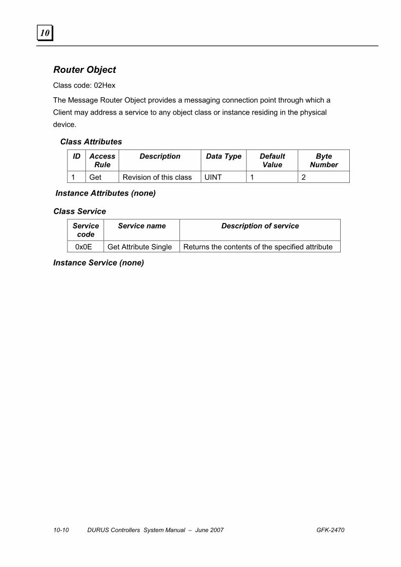
10-10 DURUS Controllers System Manual – June 2007 GFK-2470
10
Router Object Class code: 02Hex
The Message Router Object provides a messaging connection point through which a Client may address a service to any object class or instance residing in the physical device.
Class Attributes
ID Access Rule
Description Data Type Default Value
Byte Number
1 Get Revision of this class UINT 1 2
Instance Attributes (none)
Class Service
Service code
Service name Description of service
0x0E Get Attribute Single Returns the contents of the specified attribute
Instance Service (none)
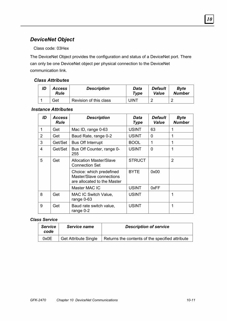
GFK-2470 Chapter 10 DeviceNet Communications 10-11
10
DeviceNet Object Class code: 03Hex
The DeviceNet Object provides the configuration and status of a DeviceNet port. There can only be one DeviceNet object per physical connection to the DeviceNet communication link.
Class Attributes
ID Access Rule
Description Data Type
Default Value
Byte Number
1 Get Revision of this class UINT 2 2
Instance Attributes
ID Access Rule
Description Data Type
Default Value
Byte Number
1 Get Mac ID, range 0-63 USINT 63 1 2 Get Baud Rate, range 0-2 USINT 0 1 3 Get/Set Bus Off Interrupt BOOL 1 1 4 Get/Set Bus Off Counter, range 0-
255 USINT 0 1
Allocation Master/Slave Connection Set
STRUCT 2
Choice: which predefined Master/Slave connections are allocated to the Master
BYTE 0x00
5 Get
Master MAC IC USINT 0xFF 8 Get MAC IC Switch Value,
range 0-63 USINT 1
9 Get Baud rate switch value, range 0-2
USINT 1
Class Service Service
code Service name Description of service
0x0E Get Attribute Single Returns the contents of the specified attribute
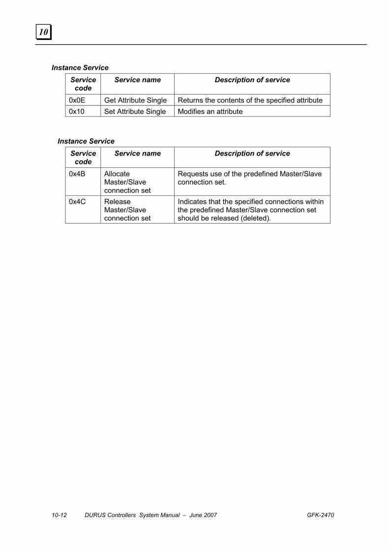
10-12 DURUS Controllers System Manual – June 2007 GFK-2470
10
Instance Service Service
code Service name Description of service
0x0E Get Attribute Single Returns the contents of the specified attribute 0x10 Set Attribute Single Modifies an attribute
Instance Service Service
code Service name Description of service
0x4B Allocate Master/Slave connection set
Requests use of the predefined Master/Slave connection set.
0x4C Release Master/Slave connection set
Indicates that the specified connections within the predefined Master/Slave connection set should be released (deleted).
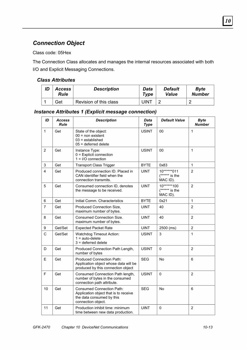
GFK-2470 Chapter 10 DeviceNet Communications 10-13
10
Connection Object Class code: 05Hex
The Connection Class allocates and manages the internal resources associated with both I/O and Explicit Messaging Connections.
Class Attributes
ID Access Rule
Description Data Type
Default Value
Byte Number
1 Get Revision of this class UINT 2 2
Instance Attributes 1 (Explicit message connection) ID Access
Rule Description Data
Type Default Value Byte
Number
1 Get State of the object: 00 = non existent 03 = established 05 = deferred delete
USINT 00 1
2 Get Instance Type: 0 = Explicit connection 1 = I/O connection
USINT 00 1
3 Get Transport Class Trigger BYTE 0x83 1 4 Get Produced connection ID. Placed in
CAN identifier field when the connection transmits.
UINT 10******011 (****** is the MAC ID).
2
5 Get Consumed connection ID, denotes the message to be received.
UINT 10******100 (****** is the MAC ID).
2
6 Get Initial Comm. Characteristics BYTE 0x21 1 7 Get Produced Connection Size,
maximum number of bytes. UINT 40 2
8 Get Consumed Connection Size. maximum number of bytes.
UINT 40 2
9 Get/Set Expected Packet Rate UINT 2500 (ms) 2 C Get/Set Watchdog Timeout Action:
1 = auto-delete 3 = deferred delete
USINT 3 1
D Get Produced Connection Path Length, number of bytes
USINT 0 2
E Get Produced Connection Path: Application object whose data will be produced by this connection object
SEG No 6
F Get Consumed Connection Path length, number of bytes in the consumed connection path attribute.
USINT 0 2
10 Get Consumed Connection Path: Application object that is to receive the data consumed by this connection object.
SEG No 6
11 Get Production inhibit time: minimum time between new data production.
UINT 0 2
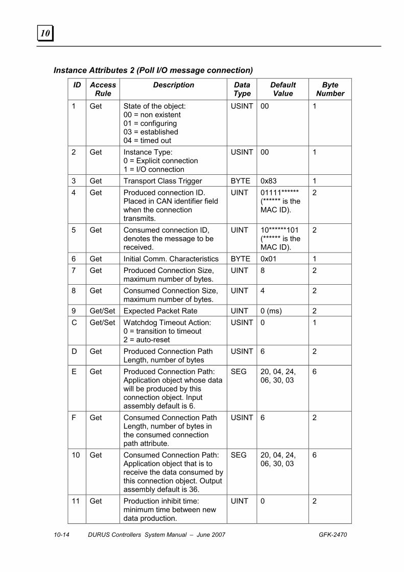
10-14 DURUS Controllers System Manual – June 2007 GFK-2470
10
Instance Attributes 2 (Poll I/O message connection)
ID Access Rule
Description Data Type
Default Value
Byte Number
1 Get State of the object: 00 = non existent 01 = configuring 03 = established 04 = timed out
USINT 00 1
2 Get Instance Type: 0 = Explicit connection 1 = I/O connection
USINT 00 1
3 Get Transport Class Trigger BYTE 0x83 1 4 Get Produced connection ID.
Placed in CAN identifier field when the connection transmits.
UINT 01111****** (****** is the MAC ID).
2
5 Get Consumed connection ID, denotes the message to be received.
UINT 10******101 (****** is the MAC ID).
2
6 Get Initial Comm. Characteristics BYTE 0x01 1 7 Get Produced Connection Size,
maximum number of bytes. UINT 8 2
8 Get Consumed Connection Size, maximum number of bytes.
UINT 4 2
9 Get/Set Expected Packet Rate UINT 0 (ms) 2 C Get/Set Watchdog Timeout Action:
0 = transition to timeout 2 = auto-reset
USINT 0 1
D Get Produced Connection Path Length, number of bytes
USINT 6 2
E Get Produced Connection Path: Application object whose data will be produced by this connection object. Input assembly default is 6.
SEG 20, 04, 24, 06, 30, 03
6
F Get Consumed Connection Path Length, number of bytes in the consumed connection path attribute.
USINT 6 2
10 Get Consumed Connection Path: Application object that is to receive the data consumed by this connection object. Output assembly default is 36.
SEG 20, 04, 24, 06, 30, 03
6
11 Get Production inhibit time: minimum time between new data production.
UINT 0 2
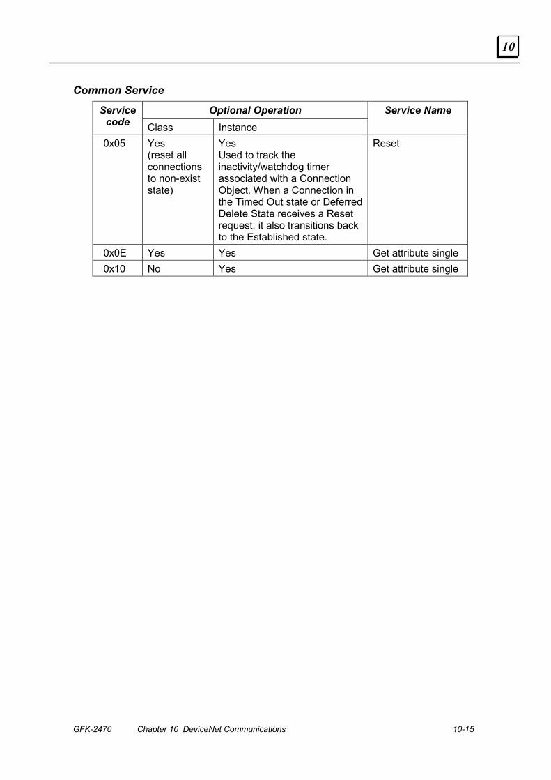
GFK-2470 Chapter 10 DeviceNet Communications 10-15
10
Common Service
Optional Operation Service code Class Instance
Service Name
0x05 Yes (reset all connections to non-exist state)
Yes Used to track the inactivity/watchdog timer associated with a Connection Object. When a Connection in the Timed Out state or Deferred Delete State receives a Reset request, it also transitions back to the Established state.
Reset
0x0E Yes Yes Get attribute single 0x10 No Yes Get attribute single
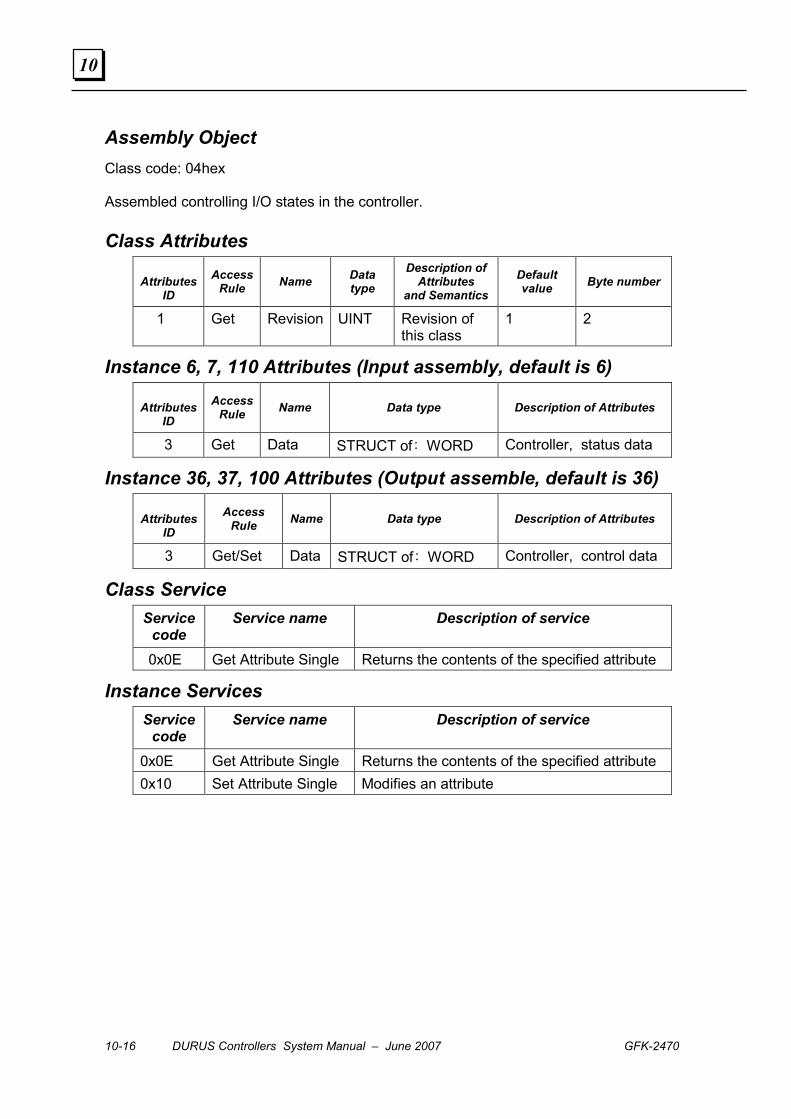
10-16 DURUS Controllers System Manual – June 2007 GFK-2470
10
Assembly Object Class code: 04hex
Assembled controlling I/O states in the controller.
Class Attributes
Attributes ID
Access Rule Name Data
type Description of
Attributes and Semantics
Default value Byte number
1 Get Revision UINT Revision of this class
1 2
Instance 6, 7, 110 Attributes (Input assembly, default is 6)
Attributes ID
Access Rule Name Data type Description of Attributes
3 Get Data STRUCT of: WORD Controller, status data
Instance 36, 37, 100 Attributes (Output assemble, default is 36)
Attributes ID
Access Rule Name Data type Description of Attributes
3 Get/Set Data STRUCT of: WORD Controller, control data
Class Service Service
code Service name Description of service
0x0E Get Attribute Single Returns the contents of the specified attribute
Instance Services Service
code Service name Description of service
0x0E Get Attribute Single Returns the contents of the specified attribute 0x10 Set Attribute Single Modifies an attribute
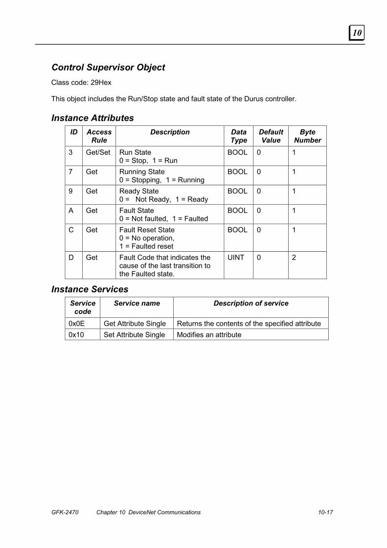
GFK-2470 Chapter 10 DeviceNet Communications 10-17
10
Control Supervisor Object Class code: 29Hex
This object includes the Run/Stop state and fault state of the Durus controller.
Instance Attributes ID Access
Rule Description Data
Type Default Value
Byte Number
3 Get/Set Run State 0 = Stop, 1 = Run
BOOL 0 1
7 Get Running State 0 = Stopping, 1 = Running
BOOL 0 1
9 Get Ready State 0 = Not Ready, 1 = Ready
BOOL 0 1
A Get Fault State 0 = Not faulted, 1 = Faulted
BOOL 0 1
C Get Fault Reset State 0 = No operation, 1 = Faulted reset
BOOL 0 1
D Get Fault Code that indicates the cause of the last transition to the Faulted state.
UINT 0 2
Instance Services Service
code Service name Description of service
0x0E Get Attribute Single Returns the contents of the specified attribute 0x10 Set Attribute Single Modifies an attribute
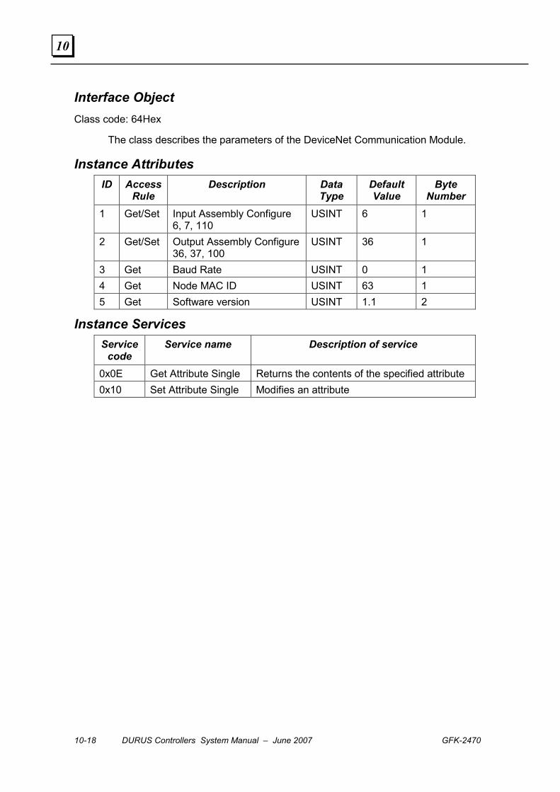
10-18 DURUS Controllers System Manual – June 2007 GFK-2470
10
Interface Object Class code: 64Hex
The class describes the parameters of the DeviceNet Communication Module.
Instance Attributes ID Access
Rule Description Data
Type Default Value
Byte Number
1 Get/Set Input Assembly Configure 6, 7, 110
USINT 6 1
2 Get/Set Output Assembly Configure36, 37, 100
USINT 36 1
3 Get Baud Rate USINT 0 1 4 Get Node MAC ID USINT 63 1 5 Get Software version USINT 1.1 2
Instance Services Service
code Service name Description of service
0x0E Get Attribute Single Returns the contents of the specified attribute 0x10 Set Attribute Single Modifies an attribute

GFK-2470 Chapter 10 DeviceNet Communications 10-19
10
Durus Controller Extended Object Class code: 65Hex
This object includes the controller’s coils data and function block values.
Instance Attributes ID Access
Rule Description Data
Type Default Value
Bytes
1 Get Controller ID Number USINT 1 1 R Coils (RTC Blocks) current states:
Byte 2, Bits Byte 1, Bits 2 Get / Set
-- F E D C B A 9 8 7 6 5 4 3 2 1
UINT 0 2
3 Get / Set G Coils (Analog Blocks) current states. See bit assignments for R Coils above.
UINT 0 2
4 Get / Set T Coils (Timer Blocks) current states. See bit assignments for R Coils above.
UINT 0 2
5 Get / Set C Coils (Counter Blockls) current states. See bit assignments for R Coils above.
UINT 0 2
6 Get / Set M Coils current states. See bit assignments for R Coils above.
UINT 0 2
I Coils (Input Points) current states Byte 2, Bits Byte 1, Bits
7 Get
-- -- -- -- C B A 9 8 7 6 5 4 3 2 1
UINT 0 2
8 Get X Coils (Extended Inputs) current states. See bit assignments for I Coils above.
UINT 0 2
Q Coils (Output Points) current states Byte 2, Bits Byte 1, Bits
9 Get / Set
-- -- -- -- -- -- -- -- 8 7 6 5 4 3 2 1
UINT 0 1
0A Get / Set Y Coils (Extended Outputs) current states. See bit assignments for I Coils above.
UINT 0 2
0B Get / Set N Coils current states. See bit assignments for R Coils above.
UINT 0 2
0C Get / Set RTC Current Value. Read Only. Byte 1 = Year, Byte 2 = Month, Byte 3 = Day, Byte 4 = Week, Byte 5 = Hour, Byte 6 = Minute Byte 8 = Second
UINT 7
0D Get PWM Current Value, running. Read Only Byte 1 = Current running number Byte 2 = Current PW Value low byte Byte 3 = Current PW Value high byte Byte 4 = Current PT Value low byte Byte 5 = Current PT Value high byte
UINT 5
0E Reserved 0F Reserved
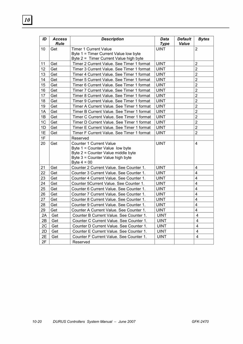
10-20 DURUS Controllers System Manual – June 2007 GFK-2470
10
ID Access Rule
Description Data Type
Default Value
Bytes
10 Get Timer 1 Current Value Byte 1 = Timer Current Value low byte Byte 2 = Timer Current Value high byte
UINT 2
11 Get Timer 2 Current Value. See Timer 1 format UINT 2 12 Get Timer 3 Current Value. See Timer 1 format UINT 2 13 Get Timer 4 Current Value. See Timer 1 format UINT 2 14 Get Timer 5 Current Value. See Timer 1 format UINT 2 15 Get Timer 6 Current Value. See Timer 1 format UINT 2 16 Get Timer 7 Current Value. See Timer 1 format UINT 2 17 Get Timer 8 Current Value. See Timer 1 format UINT 2 18 Get Timer 9 Current Value. See Timer 1 format UINT 2 19 Get Timer A Current Value. See Timer 1 format UINT 2 1A Get Timer B Current Value. See Timer 1 format UINT 2 1B Get Timer C Current Value. See Timer 1 format UINT 2 1C Get Timer D Current Value. See Timer 1 format UINT 2 1D Get Timer E Current Value. See Timer 1 format UINT 2 1E Get Timer F Current Value. See Timer 1 format UINT 2 1F Reserved 20 Get Counter 1 Current Value
Byte 1 = Counter Value low byte Byte 2 = Counter Value middle byte Byte 3 = Counter Value high byte Byte 4 = 00
UINT 4
21 Get Counter 2 Current Value. See Counter 1. UINT 4 22 Get Counter 3 Current Value. See Counter 1. UINT 4 23 Get Counter 4 Current Value. See Counter 1. UINT 4 24 Get Counter 5Current Value. See Counter 1. UINT 4 25 Get Counter 6 Current Value. See Counter 1. UINT 4 26 Get Counter 7 Current Value. See Counter 1. UINT 4 27 Get Counter 8 Current Value. See Counter 1. UINT 4 28 Get Counter 9 Current Value. See Counter 1. UINT 4 29 Get Counter A Current Value. See Counter 1. UINT 4 2A Get Counter B Current Value. See Counter 1. UINT 4 2B Get Counter C Current Value. See Counter 1. UINT 4 2C Get Counter D Current Value. See Counter 1. UINT 4 2D Get Counter E Current Value. See Counter 1. UINT 4 2E Get Counter F Current Value. See Counter 1. UINT 4 2F Reserved
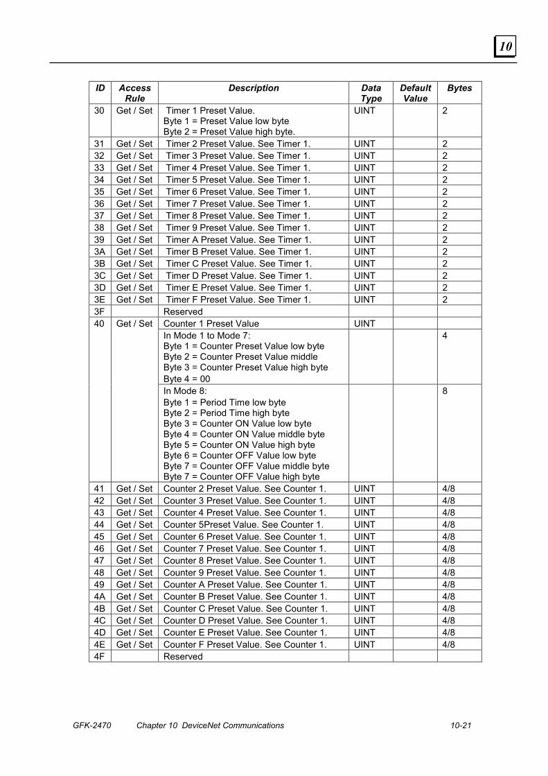
GFK-2470 Chapter 10 DeviceNet Communications 10-21
10
ID Access Rule
Description Data Type
Default Value
Bytes
30 Get / Set Timer 1 Preset Value. Byte 1 = Preset Value low byte Byte 2 = Preset Value high byte.
UINT 2
31 Get / Set Timer 2 Preset Value. See Timer 1. UINT 2 32 Get / Set Timer 3 Preset Value. See Timer 1. UINT 2 33 Get / Set Timer 4 Preset Value. See Timer 1. UINT 2 34 Get / Set Timer 5 Preset Value. See Timer 1. UINT 2 35 Get / Set Timer 6 Preset Value. See Timer 1. UINT 2 36 Get / Set Timer 7 Preset Value. See Timer 1. UINT 2 37 Get / Set Timer 8 Preset Value. See Timer 1. UINT 2 38 Get / Set Timer 9 Preset Value. See Timer 1. UINT 2 39 Get / Set Timer A Preset Value. See Timer 1. UINT 2 3A Get / Set Timer B Preset Value. See Timer 1. UINT 2 3B Get / Set Timer C Preset Value. See Timer 1. UINT 2 3C Get / Set Timer D Preset Value. See Timer 1. UINT 2 3D Get / Set Timer E Preset Value. See Timer 1. UINT 2 3E Get / Set Timer F Preset Value. See Timer 1. UINT 2 3F Reserved
Counter 1 Preset Value UINT In Mode 1 to Mode 7: Byte 1 = Counter Preset Value low byte Byte 2 = Counter Preset Value middle Byte 3 = Counter Preset Value high byte Byte 4 = 00
4 40 Get / Set
In Mode 8: Byte 1 = Period Time low byte Byte 2 = Period Time high byte Byte 3 = Counter ON Value low byte Byte 4 = Counter ON Value middle byte Byte 5 = Counter ON Value high byte Byte 6 = Counter OFF Value low byte Byte 7 = Counter OFF Value middle byte Byte 7 = Counter OFF Value high byte
8
41 Get / Set Counter 2 Preset Value. See Counter 1. UINT 4/8 42 Get / Set Counter 3 Preset Value. See Counter 1. UINT 4/8 43 Get / Set Counter 4 Preset Value. See Counter 1. UINT 4/8 44 Get / Set Counter 5Preset Value. See Counter 1. UINT 4/8 45 Get / Set Counter 6 Preset Value. See Counter 1. UINT 4/8 46 Get / Set Counter 7 Preset Value. See Counter 1. UINT 4/8 47 Get / Set Counter 8 Preset Value. See Counter 1. UINT 4/8 48 Get / Set Counter 9 Preset Value. See Counter 1. UINT 4/8 49 Get / Set Counter A Preset Value. See Counter 1. UINT 4/8 4A Get / Set Counter B Preset Value. See Counter 1. UINT 4/8 4B Get / Set Counter C Preset Value. See Counter 1. UINT 4/8 4C Get / Set Counter D Preset Value. See Counter 1. UINT 4/8 4D Get / Set Counter E Preset Value. See Counter 1. UINT 4/8 4E Get / Set Counter F Preset Value. See Counter 1. UINT 4/8 4F Reserved

10-22 DURUS Controllers System Manual – June 2007 GFK-2470
10
ID Access Rule
Description Data Type
Default Value
Bytes
RTC 1 Preset Value Mode 1 and Mode 2: Byte 1 = On week, Byte 2 = Off week Byte 3 = On hour, Byte 4 = On minute Byte 5 = Off hour, Byte 6 = Off minute
50 Get / Set
Mode 3: Byte 1 = On year, Byte 2 = Off year Byte 3 = On month, Byte 4 = On day Byte 5 = Off month, Byte 6 = Off day
UINT 6
51 Get / Set RTC 2 Preset Value. See RTC Preset 1. UINT 6 52 Get / Set RTC 3 Preset Value. See RTC Preset 1. UINT 6 53 Get / Set RTC 4 Preset Value. See RTC Preset 1. UINT 6 54 Get / Set RTC 5 Preset Value. See RTC Preset 1. UINT 6 55 Get / Set RTC 6 Preset Value. See RTC Preset 1. UINT 6 56 Get / Set RTC 7 Preset Value. See RTC Preset 1. UINT 6 57 Get / Set RTC 8 Preset Value. See RTC Preset 1. UINT 6 58 Get / Set RTC 9 Preset Value. See RTC Preset 1. UINT 6 59 Get / Set RTC A Preset Value. See RTC Preset 1. UINT 6 5A Get / Set RTC B Preset Value UINT 6 5B Get / Set RTC C Preset Value UINT 6 5C Get / Set RTC D Preset Value UINT 6 5D Get / Set RTC E Preset Value UINT 6 5E Get / Set RTC F Preset Value UINT 6 5F Reserved 60 Get / Set Analog 1 Preset Value:
Byte 1 = low byte, Byte 2 = high byte UINT 2
61 Get / Set Analog 2 Preset Value. See Analog 1. UINT 2 62 Get / Set Analog 3 Preset Value. See Analog 1. UINT 2 63 Get / Set Analog 4 Preset Value. See Analog 1. UINT 2 64 Get / Set Analog 5 Preset Value. See Analog 1. UINT 2 65 Get / Set Analog 6 Preset Value. See Analog 1. UINT 2 66 Get / Set Analog 7 Preset Value. See Analog 1. UINT 2 67 Get / Set Analog 8 Preset Value. See Analog 1. UINT 2 68 Get / Set Analog 9 Preset Value. See Analog 1. UINT 2 69 Get / Set Analog A Preset Value. See Analog 1. UINT 2 6A Get / Set Analog B Preset Value. See Analog 1. UINT 2 6B Get / Set Analog C Preset Value. See Analog 1. UINT 2 6C Get / Set Analog D Preset Value. See Analog 1. UINT 2 6D Get / Set Analog E Preset Value. See Analog 1. UINT 2 6E Get / Set Analog F Preset Value. See Analog 1. UINT 2 6F Reserved
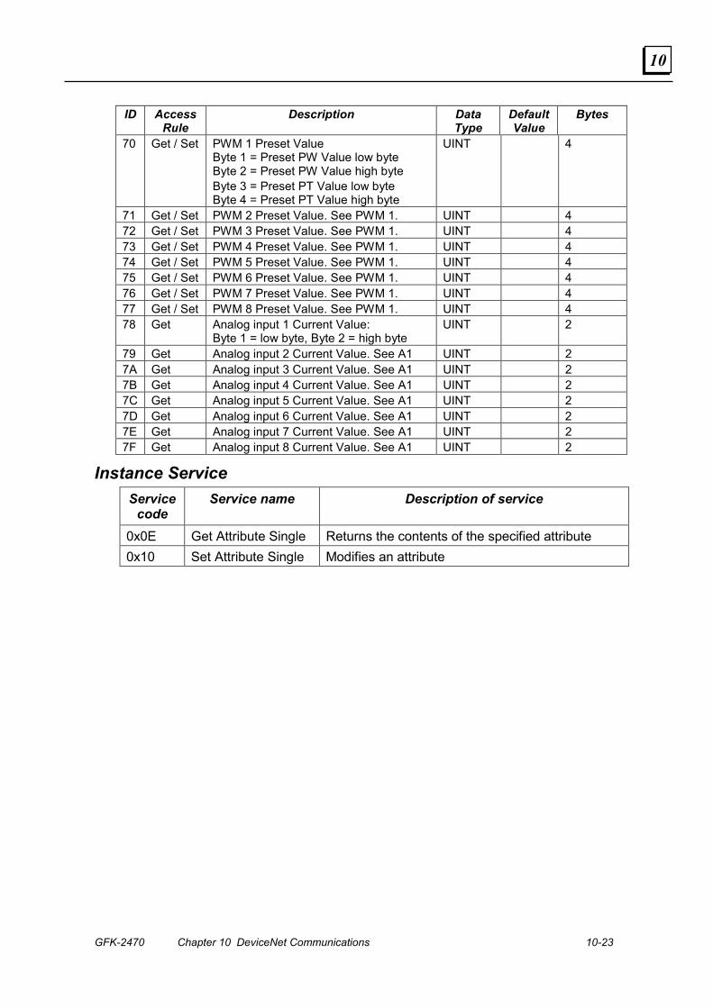
GFK-2470 Chapter 10 DeviceNet Communications 10-23
10
ID Access Rule
Description Data Type
Default Value
Bytes
70 Get / Set PWM 1 Preset Value Byte 1 = Preset PW Value low byte Byte 2 = Preset PW Value high byte Byte 3 = Preset PT Value low byte Byte 4 = Preset PT Value high byte
UINT 4
71 Get / Set PWM 2 Preset Value. See PWM 1. UINT 4 72 Get / Set PWM 3 Preset Value. See PWM 1. UINT 4 73 Get / Set PWM 4 Preset Value. See PWM 1. UINT 4 74 Get / Set PWM 5 Preset Value. See PWM 1. UINT 4 75 Get / Set PWM 6 Preset Value. See PWM 1. UINT 4 76 Get / Set PWM 7 Preset Value. See PWM 1. UINT 4 77 Get / Set PWM 8 Preset Value. See PWM 1. UINT 4 78 Get Analog input 1 Current Value:
Byte 1 = low byte, Byte 2 = high byte UINT 2
79 Get Analog input 2 Current Value. See A1 UINT 2 7A Get Analog input 3 Current Value. See A1 UINT 2 7B Get Analog input 4 Current Value. See A1 UINT 2 7C Get Analog input 5 Current Value. See A1 UINT 2 7D Get Analog input 6 Current Value. See A1 UINT 2 7E Get Analog input 7 Current Value. See A1 UINT 2 7F Get Analog input 8 Current Value. See A1 UINT 2
Instance Service Service
code Service name Description of service
0x0E Get Attribute Single Returns the contents of the specified attribute 0x10 Set Attribute Single Modifies an attribute

10-24 DURUS Controllers System Manual – June 2007 GFK-2470
10
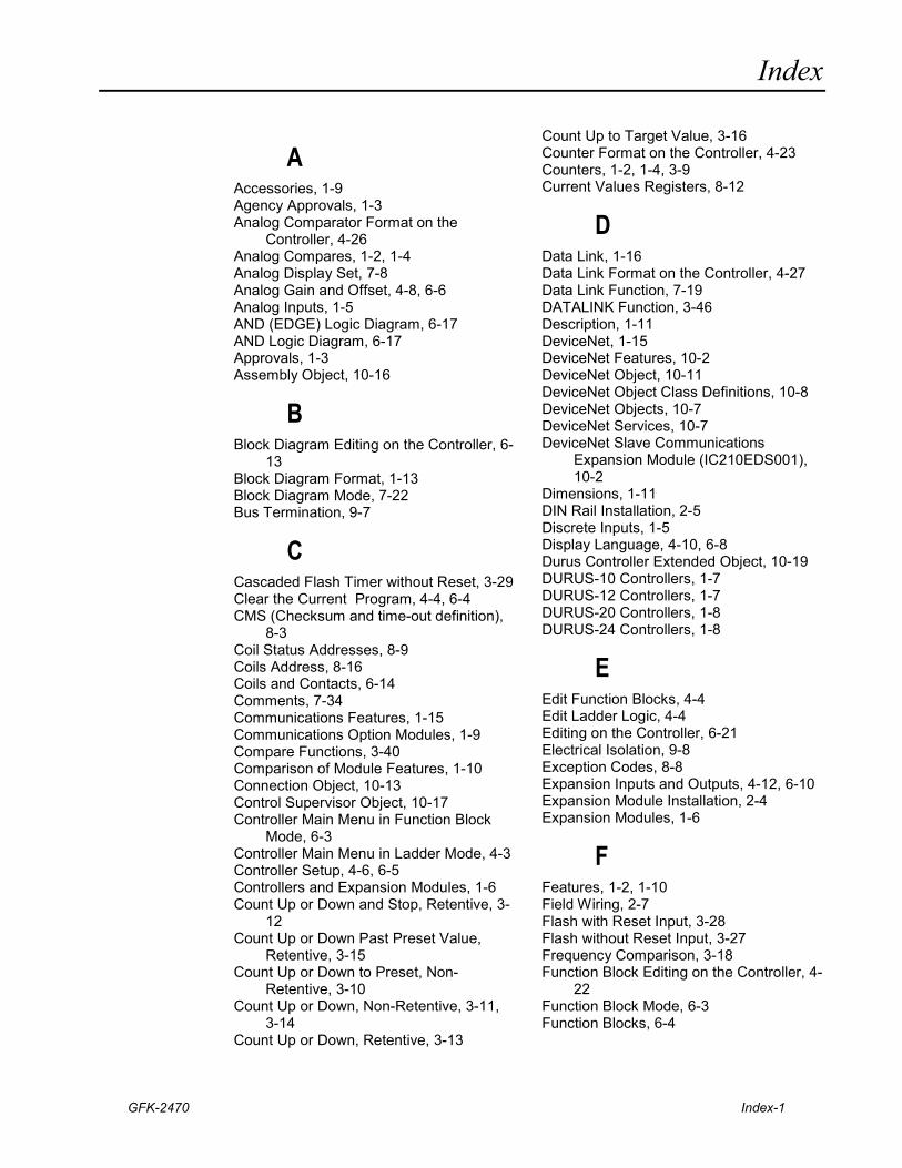
Index
GFK-2470 Index-1
A Accessories, 1-9 Agency Approvals, 1-3 Analog Comparator Format on the
Controller, 4-26 Analog Compares, 1-2, 1-4 Analog Display Set, 7-8 Analog Gain and Offset, 4-8, 6-6 Analog Inputs, 1-5 AND (EDGE) Logic Diagram, 6-17 AND Logic Diagram, 6-17 Approvals, 1-3 Assembly Object, 10-16
B Block Diagram Editing on the Controller, 6-
13 Block Diagram Format, 1-13 Block Diagram Mode, 7-22 Bus Termination, 9-7
C Cascaded Flash Timer without Reset, 3-29 Clear the Current Program, 4-4, 6-4 CMS (Checksum and time-out definition),
8-3 Coil Status Addresses, 8-9 Coils Address, 8-16 Coils and Contacts, 6-14 Comments, 7-34 Communications Features, 1-15 Communications Option Modules, 1-9 Compare Functions, 3-40 Comparison of Module Features, 1-10 Connection Object, 10-13 Control Supervisor Object, 10-17 Controller Main Menu in Function Block
Mode, 6-3 Controller Main Menu in Ladder Mode, 4-3 Controller Setup, 4-6, 6-5 Controllers and Expansion Modules, 1-6 Count Up or Down and Stop, Retentive, 3-
12 Count Up or Down Past Preset Value,
Retentive, 3-15 Count Up or Down to Preset, Non-
Retentive, 3-10 Count Up or Down, Non-Retentive, 3-11,
3-14 Count Up or Down, Retentive, 3-13
Count Up to Target Value, 3-16 Counter Format on the Controller, 4-23 Counters, 1-2, 1-4, 3-9 Current Values Registers, 8-12
D Data Link, 1-16 Data Link Format on the Controller, 4-27 Data Link Function, 7-19 DATALINK Function, 3-46 Description, 1-11 DeviceNet, 1-15 DeviceNet Features, 10-2 DeviceNet Object, 10-11 DeviceNet Object Class Definitions, 10-8 DeviceNet Objects, 10-7 DeviceNet Services, 10-7 DeviceNet Slave Communications
Expansion Module (IC210EDS001), 10-2
Dimensions, 1-11 DIN Rail Installation, 2-5 Discrete Inputs, 1-5 Display Language, 4-10, 6-8 Durus Controller Extended Object, 10-19 DURUS-10 Controllers, 1-7 DURUS-12 Controllers, 1-7 DURUS-20 Controllers, 1-8 DURUS-24 Controllers, 1-8
E Edit Function Blocks, 4-4 Edit Ladder Logic, 4-4 Editing on the Controller, 6-21 Electrical Isolation, 9-8 Exception Codes, 8-8 Expansion Inputs and Outputs, 4-12, 6-10 Expansion Module Installation, 2-4 Expansion Modules, 1-6
F Features, 1-2, 1-10 Field Wiring, 2-7 Flash with Reset Input, 3-28 Flash without Reset Input, 3-27 Frequency Comparison, 3-18 Function Block Editing on the Controller, 4-
22 Function Block Mode, 6-3 Function Blocks, 6-4
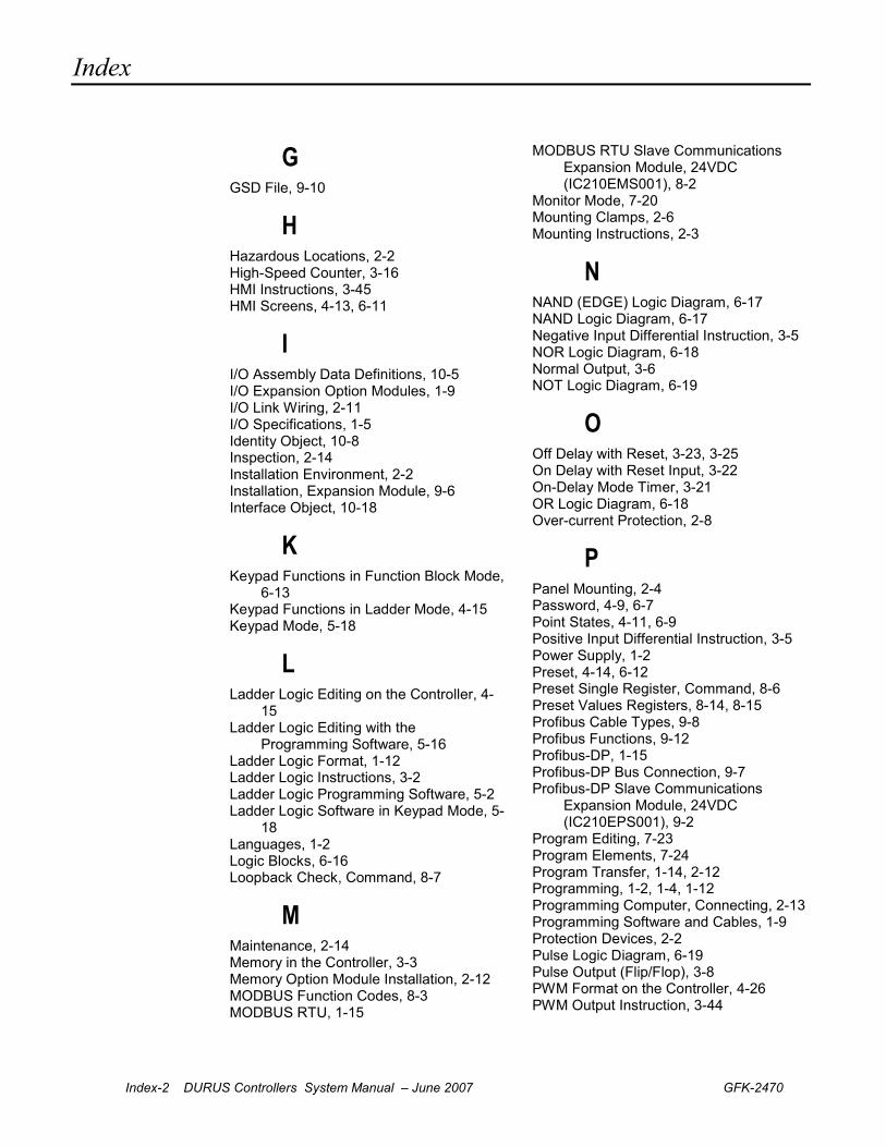
Index
Index-2 DURUS Controllers System Manual – June 2007 GFK-2470
G GSD File, 9-10
H Hazardous Locations, 2-2 High-Speed Counter, 3-16 HMI Instructions, 3-45 HMI Screens, 4-13, 6-11
I I/O Assembly Data Definitions, 10-5 I/O Expansion Option Modules, 1-9 I/O Link Wiring, 2-11 I/O Specifications, 1-5 Identity Object, 10-8 Inspection, 2-14 Installation Environment, 2-2 Installation, Expansion Module, 9-6 Interface Object, 10-18
K Keypad Functions in Function Block Mode,
6-13 Keypad Functions in Ladder Mode, 4-15 Keypad Mode, 5-18
L Ladder Logic Editing on the Controller, 4-
15 Ladder Logic Editing with the
Programming Software, 5-16 Ladder Logic Format, 1-12 Ladder Logic Instructions, 3-2 Ladder Logic Programming Software, 5-2 Ladder Logic Software in Keypad Mode, 5-
18 Languages, 1-2 Logic Blocks, 6-16 Loopback Check, Command, 8-7
M Maintenance, 2-14 Memory in the Controller, 3-3 Memory Option Module Installation, 2-12 MODBUS Function Codes, 8-3 MODBUS RTU, 1-15
MODBUS RTU Slave Communications Expansion Module, 24VDC (IC210EMS001), 8-2
Monitor Mode, 7-20 Mounting Clamps, 2-6 Mounting Instructions, 2-3
N NAND (EDGE) Logic Diagram, 6-17 NAND Logic Diagram, 6-17 Negative Input Differential Instruction, 3-5 NOR Logic Diagram, 6-18 Normal Output, 3-6 NOT Logic Diagram, 6-19
O Off Delay with Reset, 3-23, 3-25 On Delay with Reset Input, 3-22 On-Delay Mode Timer, 3-21 OR Logic Diagram, 6-18 Over-current Protection, 2-8
P Panel Mounting, 2-4 Password, 4-9, 6-7 Point States, 4-11, 6-9 Positive Input Differential Instruction, 3-5 Power Supply, 1-2 Preset, 4-14, 6-12 Preset Single Register, Command, 8-6 Preset Values Registers, 8-14, 8-15 Profibus Cable Types, 9-8 Profibus Functions, 9-12 Profibus-DP, 1-15 Profibus-DP Bus Connection, 9-7 Profibus-DP Slave Communications
Expansion Module, 24VDC (IC210EPS001), 9-2
Program Editing, 7-23 Program Elements, 7-24 Program Transfer, 1-14, 2-12 Programming, 1-2, 1-4, 1-12 Programming Computer, Connecting, 2-13 Programming Software and Cables, 1-9 Protection Devices, 2-2 Pulse Logic Diagram, 6-19 Pulse Output (Flip/Flop), 3-8 PWM Format on the Controller, 4-26 PWM Output Instruction, 3-44
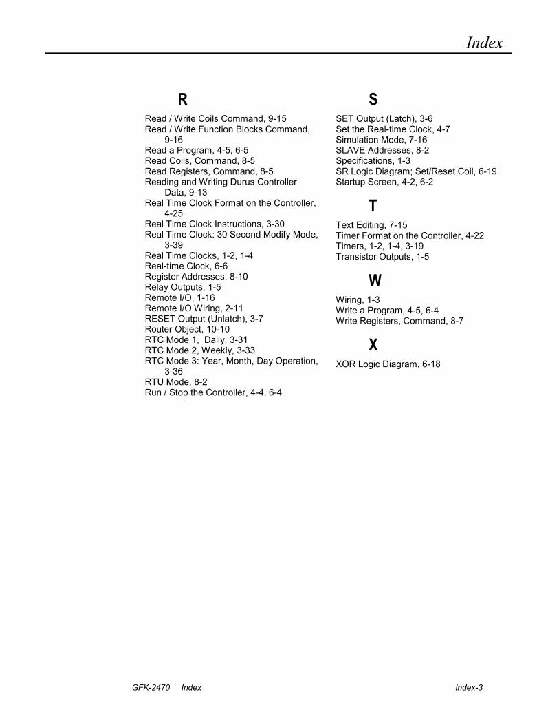
Index
GFK-2470 Index Index-3
R Read / Write Coils Command, 9-15 Read / Write Function Blocks Command,
9-16 Read a Program, 4-5, 6-5 Read Coils, Command, 8-5 Read Registers, Command, 8-5 Reading and Writing Durus Controller
Data, 9-13 Real Time Clock Format on the Controller,
4-25 Real Time Clock Instructions, 3-30 Real Time Clock: 30 Second Modify Mode,
3-39 Real Time Clocks, 1-2, 1-4 Real-time Clock, 6-6 Register Addresses, 8-10 Relay Outputs, 1-5 Remote I/O, 1-16 Remote I/O Wiring, 2-11 RESET Output (Unlatch), 3-7 Router Object, 10-10 RTC Mode 1, Daily, 3-31 RTC Mode 2, Weekly, 3-33 RTC Mode 3: Year, Month, Day Operation,
3-36 RTU Mode, 8-2 Run / Stop the Controller, 4-4, 6-4
S SET Output (Latch), 3-6 Set the Real-time Clock, 4-7 Simulation Mode, 7-16 SLAVE Addresses, 8-2 Specifications, 1-3 SR Logic Diagram; Set/Reset Coil, 6-19 Startup Screen, 4-2, 6-2
T Text Editing, 7-15 Timer Format on the Controller, 4-22 Timers, 1-2, 1-4, 3-19 Transistor Outputs, 1-5
W Wiring, 1-3 Write a Program, 4-5, 6-4 Write Registers, Command, 8-7
X XOR Logic Diagram, 6-18