dust collected in mast and in tore supra - freecrwth.free.fr/images/3-14.pdf · 1. dust collected...
TRANSCRIPT

11
Dust collected in MAST and in Tore SupraC. Pardanaud1, C. Martin1, P. Roubin1, C. Arnas1 and G. De Temmerman2
1 Lab. PIIM, CNRS-Université de Provence, UMR 6633, 13397 Marseille, France2 EURATOM/UKAEA Fusion association Culham Science Center, Abingdon, UK
Nanoparticle growth in laboratory plasmasA. Mouberi1, C. Arnas 1, F. Bénédic 2, G. Lombardi 2, K. Hassouni2, X. Bonnin2
1Lab. PIIM, CNRS-Université de Provence, UMR 6633, 13397 Marseille, France2LIMHP, UPR 1311 CNRS, Université Paris XIII, Villetaneuse, France
Association EURATOM-CEA
FDR-FCM

2
Outline
Dust produced in the MAST tokamak
quantitative analyses (mass)
qualitative analyses (shape, structure, composition)
Dust collected in Tore Supra neutralizers
qualitative analyses (shape, structure, composition)
Carbonaceous nanoparticles growth in laboratory plasmas
graphite cathode sputtering in DC discharges
microwave discharges in Ar/CH4/H2
Conclusion (similarities, differences)

3
8 locations of collection by vacuuming below mid-plane. 3 groups of location:
erosion-dominated locations swept by strike points (foot of the central column, tiles)
private flux region (dome)
shadowed locations (toroidal gaps, ports, under Langmuir probe, upper surface of magnetic coils)
PFCs: graphite, stainless steel
M6 campain (2006-2007) = 2 x 2000 shots de 0.3 s
Dust collected in the MAST tokamak
xx

44
Qualitative analyses: SEM, TEM, HRTEM, EDX, IR absorption spectroscopy, Raman microscopy
Quantitative analyses
outer toroidal gap of tiles + inner toroidal gap of tiles, m = (29.6 + 4.8) mg
ports, m = 4.2 mg
dome, m = 4.1 mg -> 1.86 mg/m²
tiles, m = 3.9 mg -> 0.52 mg/m²
Total mass > 46.6 mg (2 1018 atomes/s)
dust transport towards shadowed areassweeping of the outer strike point towards the tile outer toroidal gap (dust transport)private flux region = domeeroded-dominated regions = tiles
⇒
Consistent with dust transport and formation
Dust collected in the MAST tokamak

55
1) metallic particles (nm to µm size)arcing on vessel and magnetic coils (stainless steel)
metallic impurities during plasma ignition on inductive coils
2) carbonaceous grains (~ µm), irregular shape heterogeneous structure (amorphous to graphite-like)
coming from redeposited layers when they contain metallic impurities
otherwise, pulled out from divertors during disruption
3) carbonaceous nanoparticles, different structure (amorphous, onion-like)
Evidence of homogeneous growth:consistent with divertor plasma: dense and cold
Nanoparticles (5-10nm)
SEM, TEM, HRTEM show everywhere:

66
Raman micro-spectroscopyfor a given location, heterogeneous structure:
amorphous carbon to disordered graphite
the most amorphous grains located on the dome surface (private- flux region)
IR absorption spectroscopy
CD, CH, aromatic C=C , C≡C
1000 1100 1200 1300 1400 1500 1600 1700 1800
Raman shift (cm-1)
box 31 grain 1 box 31 grain 2 box 31 grain 3 box 31 grain 6
Dust in the outer toroidal gap of tiles (shadowed area):
Plan: Raman micro-spectroscopy currently done - correlation between the features deduced from spectra and the corresponding surface area collection

7
Dust in the Tore Supra tokamak
neutralizer
toroidallimiter
neutralizer
toroidallimiter
Deposits collected on the leading edge of neutralizers (PhD M. Richou)

1
200 μm200 μm200 μm 20 μm20 μm20 μm
1 μm
●
self-similar tips●
parallel tip-axes●
concentric shells●
porosity
network
heterogeneous growthwith specific features

9
20 nm20 nm
●
locally graphitic
structure●
onion-like particles similar
to
carbon
black●
graphite-encapsulated metal
nanoparticules
evidence of homogeneous growthin the edge plasma

10
Nanoparticles produced in tokamak edge plasmas, divertor plasmas
2 stages of growth in cold plasmas:
1) molecular precursors (complex chemical pathway) nucleation
2) growth of nanoparticles
sputtering (physical erosion)
CH4 release (chemical erosion)Tokamaks with graphitic PFCs:
(TEXTOR, TS, MAST …)
11
From hydrocarbon species in microwave discharges
experimental set up
molecular precursors, nanoparticles growth
From cathode sputtering in DC discharges
experimental set up
molecular precursors, nanoparticle growth
2 examples of carbon nanoparticle growth in laboratory plasmas:

12
1 : Graphite cathode 4 : Langmuir probe2 : Anode 5 : Thermocouple3 : Dust collector 6 : Optical window
1
23
5
4 6
• Emission spectroscopy• Laser extinction and diffusion
⇒
• Argon = 0.6 mbar• Vpol ~ - 600 V• P ~ 100 W• J ~ 10 A/m²
200 nm
Ne = Ni ~ 1010 cm-3 , Te = 3 eV dans la LN
Glow discharges
13
0
3
6
9
12
0 0,2 0,4 0,6
E (eV)
EDF
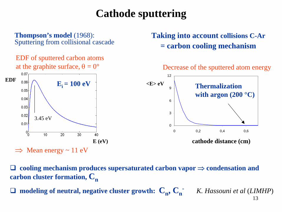
3.45 eV
Decrease of the sputtered atom energy
cathode distance (cm)
Thompson’s model (1968):Sputtering from collisional cascade
EDF of sputtered carbon atoms at the graphite surface, θ
= 0°
Thermalization with argon (200 °C)
⇒
Mean energy ~ 11 eV
Cathode sputtering
<E> eV
Taking into account collisions C-Ar= carbon cooling mechanism
cooling mechanism produces supersaturated carbon vapor ⇒ condensation and carbon cluster formation, Cn
Ei = 100 eV
modeling of neutral, negative cluster growth: Cn, Cn- K. Hassouni et al (LIMHP)

14
0
10
20
30
40
50
60
70
80
0 30 60 90 120 150 180 210 240 270 300 330 360 390 420 450 480 510 540
Durée de la décharge (s)
Taill
e (n
m)
Growth by cluster deposition
agglomeration of nucleus of 2-3 nm size+ deposition 8 nm
agglomeration of nanoparticules, 6-15 nm size + deposition
~ 40 nm
Experimental growth law
15
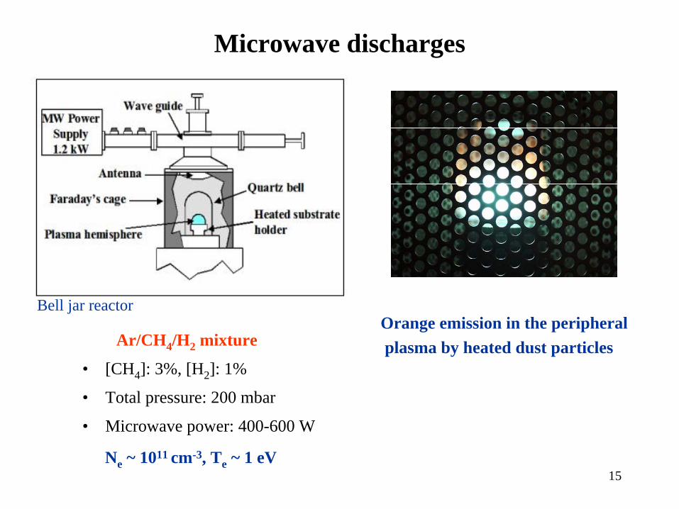
Ar/CH4 /H2 mixture
• [CH4 ]: 3%, [H2 ]: 1%
• Total pressure: 200 mbar
• Microwave power: 400-600 W
Bell jar reactorOrange emission in the peripheral plasma by heated dust particles
Microwave discharges
Ne ~ 1011 cm-3, Te ~ 1 eV

16
C CH H2 C=C=C=CH
H H+ H
• Mechanism of Poly-Aromatic Hydrocarbons (PAHs) formation(1)
A4 model (K. Hassouni)Radicalar
growth
of PAH
and nucleation mechanism
Linearization
Cyclization
CH HC
HCCH
CH
C
HC C CH
+ C2 H2
- H
+ H
- H2
HC
HCCH
CH
CC C CH
CH
CH
C
HC
…….
+ C2 H2
- H
cyclisation
Hydrogen Abstraction Carbon Addition (HACA)
CH
CHHCCH
CCH
CHHCCH
C
+
Condensation of 2 pyrene (A4) molecules
nanoparticle nucleous
(1) Wang et Frenklach., Comb.Flame (1997)
C=C=C=CH
H H+ C CH H
CH

17
3 nm
in-situ IR absorption spectroscopy (diode laser): presence of C≡C
ex-situ IR absorption spectroscopy: presence of PAHs with 3, 4 aromatic rings
chromatography in gas phase: presence of PAHs with 2, 3, 4 aromatic rings
HRTEM micrographs
0.1µm

3 nm
1) carbon sputtering discharges: low pressure, low input power
1)2)
Conclusion (1/2)
2.5 nm
2) Ar/CH4 /H2 discharges: higher pressure, higher input power
3)Tore Supra (limiter tokamak)
4)MAST (divertor tokamak)
3) 4)
2 nm5 nm
Conclusion (1/2)Nanoparticles produced in different plasma conditions have similar structure

1) IR absorption spectroscopy:- TS neutralizers deposits : flat spectra- MAST: one spectrum (CD, CH, C=C, C≡C)
Molecular precursors in Tore Supra and MAST?
2) Mass spectrometer (Tore Supra)3) Chromatography analyses?
1) carbon sputtering discharges: Cn , Cn-
2) Ar/CH4 /H2 discharges: complex chemical pathway ⇒ PAHs
Confirmation:1) Chromatography2) IR absorption spectroscopy 3) Mass spectrometer (plan)
But, in the considered laboratory plasmas, molecular precursors are different :