dvr-20~1
TRANSCRIPT

C0NQ.140.417
DVR-2000B Excitation Regulator
User Guide
NANJING TURBINE & ELECTRIC MACHINERY GROUP
NANJING TURBINE POWER CONTROL CO.,LTD
1

Contents
1 Introduction.................................................................................................................1
2 Features and Applications...........................................................................2
2.1 Product Festures...............................................................................................................2
2.2 Application areas..............................................................................................................3
2.3 Operating condition..........................................................................................................3
3 Functional Overview and Specification.......................................4
3.1 Functional Overview.........................................................................................................4
3.1.1 Regulation and Control.........................................................................................4
3.1.2 Limit and protect...................................................................................................4
3.1.3 Other auxiliary function........................................................................................5
3.2 Summary of qualification.................................................................................................5
3.2.1 A/D input parameter..............................................................................................5
3.2.2 Switching value input and output capability.......................................................6
3.2.3 Output parameters.................................................................................................6
3.2.4 Network interface...................................................................................................6
3.2.5 Power supply parameter........................................................................................6
3.2.6 Index parameter.....................................................................................................6
4 System allocation....................................................................................................8
4.1 Electrical allocation..........................................................................................................8
4.1.1 Excitation system diagram....................................................................................8
4.1.2 Input/output interface sketch map.......................................................................8
4.1.3 Hardware component............................................................................................8
4.2 Structure allocation..........................................................................................................9
4.2.1 Cabinet constitution...............................................................................................9
4.2.2 Layered introduction.............................................................................................9
5 Fundamental Principle..................................................................................12
5.1 Fundamental Principle...................................................................................................12
5.2 Single board principle.....................................................................................................13
5.3 software instruction........................................................................................................16
5.3.1 Main dispatcher...................................................................................................16
5.3.2 Interrupt routine..................................................................................................16
2

6 Keyboard, Display and Operation.....................................................21
6.1 Key board Operation Instructions................................................................................21
6.2 Main Menu Display.........................................................................................................21
6.3 Main Menu Display.........................................................................................................23
6.3.1 Measurement display...........................................................................................23
6.3.2 Parameter Setting................................................................................................24
6.3.3 Protection Withdrawal........................................................................................28
6.3.4 Switching input status.........................................................................................28
6.3.5 Drive Test..............................................................................................................29
6.3.6 System Test...........................................................................................................29
6.3.7 Fault Recall...........................................................................................................30
6.3.8 Fault Waveform....................................................................................................31
6.3.9 Event Recording...................................................................................................31
6.3.10 Accuracy Setting.................................................................................................32
6.3.11 Unit Parameters.................................................................................................32
6.3.12 System Configuration........................................................................................33
6.3.13 Test Option..........................................................................................................34
6.3.14 Other Test...........................................................................................................34
3

1 Introduction
DVR-2000B excitation regulator is a new generation of microprocessor-based excitation
regulator, which depends on China Electric Power Research Institute, and developed by
Nanjing Turbine & Electric Machinery Group Co. Ltd. It has consummate function of
adjustment, control and limit protect, and prodigious improvement in computation speed,
anti-EMI, reliability as well as facility in use.
DVR-2000B generator excitation regulator takes the newest high speed 32-bit DSP of TI
Corporation as the core, with the auxiliary device of large scale programmable logic
controller, to make the control system on a chip and greatly improve the system stability.
Simultaneously, external plate machine and large screen LCD greatly upgrades the human-
machine interface and provide enormous convenient to the users.
1

2 Features and Applications2.1 Product FuturesDVR-2000B Excitation Regulator, as a new generation of microcomputer excitation
product, unifies the latest results of the excitation system research and many years operating
experience with the first generation of excitation regulation device. The latest computer
control technology, digital signal processor (DSP) technology and advanced network and
communication technology have been successfully applied on this new product. DVR-2000B has following features:
1. Clear and accurate model
DVR-2000B excitation control system uses the series adjustment with excitation
voltage hard negative feedback; all the models used are demonstrated to be with small
error and high precision in the discretization by computer simulation and dynamic
signal analyzer measurement.
2. High measurement accuracy
DVR-2000B excitation regulator using sampling 24 points per cycle, FFT, Completely
eliminates influence of null shift to measuring accuracy, and 14-bit A/D conversion
ensures accuracy and rapidity of measurement channel.
3. Strong network communication function
DVR-2000B excitation regulator is provided with strong communication function,
double-channel, regulator and power cabinet are connected with reliable CAN-BUS, So
as to achieve data share and coordinate control.
4. Convenient and friendly human-machine interface
DVR-2000B excitation regulator use large screen LCD (240*128), tree menu structure.
The convenient and visual menu can achieve setting parameter, measurement display,
test control, and other functions with keyboard. Test waveform fault type and event
SOE are also can be displayed on the screen, using ESM-V1.0 software package makes
realize the functions above more convenient
5. Domestic fastest excitation regulator
DVR-2000B uses the TI Corporation 32-bit DSP, whose speed is up to 150MHz.
formidable data-handling capacity and fast floating-point computation ability of DSP
provide the guarantee for the accurate digitization of excitation regulator model and
realizations of other auxiliary functions.
6. Highly integrate hardware design
DVR-2000B uses large scale programmable logic controller CPLD, which realize
conventional dozens of chips combination completed function by flexible programming,
one chip accomplish all the peripherals circuit. Less hardware decrease device fault
point, so the entire system reliability increases.
7. Handsome and practical cabinet design, advanced and normative technique of product
DVR-2000B uses standard 4U cabinet; back-insert structure makes signal-flow
direction all the same, which decrease the affect of signal cross, and increase the anti-
interference ability of the system. Cabinet uses totally increased structure, Integrated
all boards which the regulator needs inside, whose self being a system. Main boards are
all use multilayer, surface mounting technique.
2

8. Unique anti-interference design
By well-design, properly arrange earth connection, filtering, masking and other details,
DVR-2000B anti-interference ability achieve stern level 3 in Chinese standard.
2.2 Applications DVR-2000B excitation regulator is applicable for three machine (brushless) excitation
system with permanent magnetism machine excitation system.
2.3 Operating condition1. No more than 1,000 meters above sea level
2. Surrounding temperature -10℃~40℃3. Relative humidity less than 90%
4. No fire and explosion
5. No conductive dust and chemical corrosion gas
6. No strong electromagnetic interference
3

3 Functional Overview and Qualification
3.1 Functional OverviewDVR-2000B excitation regulator is mainly designed for keeping terminal voltage stabile,
distributing reactive power between parallel units by proper droop setting, increasing power
system transient stabilization and static stabilization by fast excitation response. Besides,
DVR-2000B also has some auxiliary functions such as fault wave recording,event looking back, system self checking, intelligent debugging etc.
3.1.1 Regulation and Control1. Generator constant terminal voltage PID ( proportion 、 integral 、 differential
coefficient) is achieved by Auto mode. 2. Generator constant excitation current PID is achieved by Manual mode.
3. Auto and manual mode is followed each other, realizing no disturb by the mode switch.
4. Channels is followed each other, realizing no disturb by the channel switch.
5. Generator running on Constant Trigger angel.
6. Reactive power droop setting adjusting, whose direction can be set sign; Droop setting
coefficient can be adjust 0-15% with step 0.1%
7. Static excitation system startup control
8. Possible to achieve generator unit stably running and smoothly adjusting on both load
and no load condition
9. Online parameter modify, insuring that data would not lost when power fail
10. DVR-2000B excitation system can be connected to the power plant DCS system by SCI
or Internet. So that to achieve real time data transferring to host computer and
receiving host computer instruction
11. Generator operating on Constant Power factor
12. Generator operating on Constant reactive power
3.1.2 Limit and protect1. PT(Potential Transformer) wire-broken protect, estimate wire-broken by comparing
two groups of PTs or different phases of one PT. manual switching when excitation
wire-broken or sending signal when instrument wire-broken
2. V/Hz protect,implement step limit and protect V/Hz, for protecting over-magnetic flux of generator and main transformer
3. Over-excitation limit and protect, implement step over-excitation limit and protect for
generator rotor
4. Under-excitation limit and protect
5. Over-voltage protect when no load
6. Trigger pulse lost detection
7. Communication failure detection
8. Thyristor fault detection
9. Power supply detection, monitoring if CPU power and 24V operation power are
normally working.
10. Diode or fuse failure in the rotating assembly is detected. If rotating diode or rotating
fuse is failure, the light emitting diode provides local indicaton ,at the sametime giving
4

remote alarm by DVR-2000B.
11. Limit and protect values, protect launching or cutting are all able to be set when field-
work
3.1.3 Other auxiliary function1. Fault wave recording, DVR-2000B excitation regulator record data at the time between
10 sec. before and after fault. Record data include generator voltage UG1,UG2, auto
setting value UGREF,manual setting value IFREF, trigger angle ARF, active power P, reactive power Q, rotor voltage Ufd, field current Ifd, generator frequency F0, local
cabinet output current ILA, other cabinet output current ILB. Almost all the analog
variables are included. Fault waveform can display on the LCD of the Controller, which
also can transfer to notebook by SCI, displayed, managed and printed using EMS v1.0
2. Test wave recording, DVR-2000B excitation regulator is able to record test waveforms
by manual startup, such as 10% step response, de-excitation, cutting load, etc.
Recording time is between 1 second before test start and 19 seconds after test start,
Record data are the same as fault wave recording. Display mode is the same as fault
wave recording
3. Fault recording, which is able to record 20 fault acting value, breakdown time
(millisecond precision) and fault type by the rule of FIFO, all the massage can be
display on LCD or host computer.
4. Event recording, by the rule of FIFO , which is able to record 20 fault acting value, fault
time(millisecond precision) , such as turning on or off magnetic blow-out switch ,
launching or cutting channels, changing operation mode.
5. Strong communication function, DVR-2000B uses standard MODBUS protocol, which
is able to communicate between channels and achieve interface between excitation
regulator and DCS system or other Power plant monitor system by flexible
communication mode, RS232,RS485 or CAN.6. Software potentiometer function, for which all analog variables management loops
cancel potentiometer, Menu set software potentiometer makes debugging work easier
and more flexible
7. Strong test function,which expediently running all tests by keyboard operating on controller. Such as switch variable driving test, over-excitation limit, under- excitation
limit, step response test, AC excitation machine time constant test etc, and also
proceeding auto waveform record.
3.2 Summary of qualification3.2.1 A/D input parameterA/D sample channel: 16-channel
Analog variable input general view:
Terminal voltage PT1: rated 105v
Terminal voltage PT2: rated 105v
Stator current: rated 5A (or: 1A)
Exciting current of exciter: 75mv (from LEM)
3.2.2 Switching value input and output capability
5

16-channel electric isolated input;
10-channel switching value output, where 2 channels optoelectronic output, 8 channels relay
output, which can be extended to 18 cannels.
3.2.3 Output parametersTrigger pulse: 6 phase double pulse for 3 phase full controlled bridge, whose width is 100us,
which can trigger less than 4 groups of 3 phase full controlled bridge, and give single phase
full controlled(or semi-controlled) bridge trigger pulse.
3.2.4 Network interfaceSCI1: RS-232(isolated)
SCI2: RS-485(isolated)
CAN bus: CANH,CANL(isolated)Communication protocol: standard modbus protocol
3.2.5 Power supply parameterWorking AC power supply: from PMG
Working DC power supply: DC220V±20%,or DC110V±20% 2AAuxiliary AC power supply: station-service AC220V±15% 2A
Supply power: less than 400W
3.2.6 Index parameterDVR-2000B excitation regulator satisfies well of GB/T 7409.3-1997 criteria of excitation
system for synchronous electrical machines technical requirement of excitation system for
large and medium synchronous generators. Detailed Index parameter as following:
1. CPU type: 32-bit high-speed DSP
2. CPU speed: up to 150MHz
3. Thyristor pilot angle α resolution: 0.0048 degree per yard
4. ADC resolution: 2-14,16-channel5. Control calculate speed: 3.3 ms
6. Voltage adjust range: 10%~130%7. Voltage adjust precision: <0.5%
8. Shift range: 0~170degree, upper and lower limit can be set in program 9. Droop setting: software reactive power droop setting, sign and magnitude adjust step is
±1%.
10. Frequency character: generator terminal voltage change less than ±0.25% of rated
voltage while 1% change of Frequency
11. Setting value adjusting speed: programmable, no faster than 1% per second and no
slower than 0.3% per second.
12. When no-load with rated voltage, when generator setting step is ±10%, generator
voltage overshoot is less than 30%, surge is less than twice and settle time is less than 5
second
13. When generator voltage startup from zero, terminal voltage overshoot is less than 10%,
oscillations is less than twice and adjust time is less than 5 second
6

14. Operation mode: host/standby mode
7

8

4 System configuration
4.1 Electrical allocationDVR-2000B takes simple and reliable as principle, configuring corresponding excitation
system for different excitation mode. This chapter makes an introduction and takes a 3
machine excitation system as example
4.1.1 Excitation system diagram
Fig 1 is the system block diagram of 3 machine excitation system. Under this mode, regulator
operate under host/standby mode, host/standby channel communicate each other, backup
channel work as a backup trailing channel, and also can switch without disturbance.
4.1.2 Input/output interface sketch map
Analog variable range is ±5V; operating loops all use 24v power. Respected signal
diagrammatic is as following figure:
Fig 4-1 Input/output interface
4.1.3 Hardware component
DVR-2000B excitation regulator is a highly integrated controller, including almost all
function blocks from switching power to pulse amplification. Each control channel includes:
Jump switch
Limitation& Protection
Const power factor
Const reactive power
PSS switch
Manual Run
Auto Run
Run/Trail
PSS switch in/out
Decrease magnetic
Increase magnetic
Power cabinet fault
Position
Magnetic blow-out swith
Pulse output
CAN
Rs-485
Rs-232
4-20mA
4-20mA
D/A 2
D/A 1
System voltage(optional)
Rotor voltage(output)
Rotor current (output)
AnalogInput
Signal output
Switching Variable Input
Switching Variable Output
Meter PT
Measurement PT
Stator current
Test signal
Channel switch in/out
9

1. Switching power module1 (+5V,±12V)--PWR1
2. Switching power module2 (24V1,24V2)--PWR23. Main board--CPU
4. Switch variable input and output board—DI/DO
5. Pulse amplification board--PGC
6. Analog signal conditioning board--SPB
7. PT/CT and sync transformer board—PT/CT
8. Power unit board—RE.U
9. Bus back soleplate
10. Keyboard and LCD panel
See Fig 4-1a and Fig 4-1b.
4.2 Structure allocation
4.2.1 Cabinet constitutionDVR-2000B generator microprocessor-based excitation regulators use assembling cabinet
structure. The cabinet is quite smooth and artistic, with doors fore and after. The cabinet
intensity greatly surpasses the welding cabinet. The cabinet surface uses the technology of
polyester powder coated, with the color code provided by the purchaser. The wirings of
strong electricity and weak electricity in the cabinets are separated to avoid mutual
interference. The wire used in the current circuit of control cable is 2.5 mm, while others are
1.5 mm. The wire color is distinguished according to the Chinese Standard, where AC is
distinguished by yellow, green and red. All cables are not permitted to be branched and
spliced. All wire sizes and number plates are printed with special printer to be neat and
consistent. The size of horizontal earth copper bus is no smaller than 6*25 mm2. The earth
connection of every screen is achieved by connecting the bolt ground bus to the naked metal.
Tow terminals of the bus are connected to the 120mm2/2*60mm2 (4/OAWG) copper core
ground connected cable, which comes from the ground mat of the power plant. Ground
terminals are provided on the excitation cabinet for equipment shield. The moisture-proof
heater can be installed in the cabinet, and also the lighting equipment is installed which
controlled by the door. The front of the regulator cabinet is a glass door, which is convenient
for monitoring. 20% of the terminals are reserved. The external dimension of standard
cabinet is 800*600*2260 mm (also can be decided by the user). Ventilating windows are also
installed in the cabinet up and down.
4.2.2 Layered introductionThe front and back view of self excitation and shunt excitation cabinet is shown in Fig DVR-2000B excitation cabinet assemble.1. Instrument layerIt is located in the first layer of the cabinet. The related instruments are arranged in the
front. The generator terminal voltage meter ,PMG terminal voltage meter and excitation current meter are installed generally. So it is easy to operation or monitor test on site.
2. Operation layer
10

5 console switches are installed on this layer to operate the regulator on line.
1QK:The channel selection switch is used to select CHA or CHB for current operating
channel or current following channel. In the operation, undisturbed switchover can be done
with the handle.
6QK:The channel ON/OFF switch is selection the regulator for the put in/cut off .
3QK:Mode selection switch is used to select the operation mode of the regulator, including
manual operation/ automatic operation.
5QK:Increase/decrease switch, which is a self-restoring switch, is used to adjust the
magnitude of the generator voltage or reactive power. In order to prevent the increase
/decrease switch node from conglutinating, the increase/decrease switch will be locked by the
procedure if the increase/decrease switch operates continuously over 3 seconds, revert the
switch to unblock the lock command.
4QK: Running mode switch is used to select constant Power factor control, constant
generator terminal voltage control and constant reactive power control.
2QK:Remote control/local control switch is used to decide the regulator accepts the local
control command or remote control command. The above switches are invalid while this
switch is in remote control state, and regulator is controlled by the switches on the remote
control station. When this switch is in local control state, the regulator accepts the operation
commands on the screen, and the operations on the remote control station are invalid. Make
sure to set the local control and remote control in a corresponding consistent condition
before switch the remote control and local control in the operation.
3. Control layerControl layer is the core layer (master control unit) of DVR-2000B generator microcomputer
excitation regulator. It assembles almost all the excitation regulator functional modules.
Controller uses 4U standard cabinet with surface oxidized, which looks really handsome.
Board adopts back-insert structure. Fig 4-1 is the front and back view of DVR-2000B
controller. A 240*128 large-screen liquid crystal display device, a keyboard controller and
some operation indicator lamps are mounted on the regulator board; in the right lower side
of the board there is a RS232 connector.
Fig 4-1a DVR-2000B excitation regulator front panel
11

Fig 4-1b DVR-2000B excitation regulator back panel
In the left upper side of the host control unit board is the mark of the regulator; in the left
lower side is the company name; in the middle are large-screen liquid crystal display device
and operation keyboard, about which more information can be seen in <chapter 6 keyboard,
display and operation>; in the right side of the board is operation indication area, from
upper to lower which contains: auto, manual, PSS (for generator units lower than 100MW,
PSS is not needed, which is stand-by here), constant reactive power, constant power
factor(for units upper than 100MW, this operation mode doesn’t exist, which is stand-by
here), channel fault. All the six indicator lamps listed above display green to present normal
status except the “channel fault” indicator lamp, which display red when status is normal.
The channel fault indicator lamp acts when any protects or limits act. Detailed action types
will be displayed in the top line of the LCD. If several protects act at the same time, only the
fault type of the last one is displayed here. More detailed action type, action time and action
value can be inquired in menu→fault recall.
See figure 4-4b, the boards of controller is inserted from the back of cabinet. There are 10
independent boards including two extendable stand-by boards. The boards in cabinet must
be inserted into corresponding slots by sequence. If sequence wrong, the board would be
damaged.
4 Power switch layerDVR-2000B generator microcomputer excitation regulator is two-channel supplied. Two
working power AC and DC supply the switch power in control unit through gas switches
respectively.
5. Rest parts of an apparatusIt contains supply transformer, LEM, FL1, FL2, RX, diode and relay 1k,2k,3k,4k etc.
Supply transformer transforms AC voltage to 165V/85V ±5% in the secondary. After
rectified, it is DC220/110 and supplies a regulator in parallel with station service DC power
through inverse diodes. For excitation systems whose power supply voltage is higher than
220V/110V, synchronization signal must be step down through a synchronization
transformer. LEM, FL1, FL2: is used to measured the excitation current
RE. U CPUPWR 2PWR 1
Reset
Test
Diode FaultAlarm
EXT ST
OUT EXT
-CK
-AG
-AK
-BG
-BK
-CG
24VCOM
0V2COM
+AG+AK
+BG
+BK
+CG
+CK
J10
J9IFD_T
ILD-
ILD+
IFD-
IFD+
485-
485+
CANL
CANH
OUT3
OUT2
OUT1
OUT0
IN1'
IN1
GND1GND1
DA 1
DA2
Uran
GND
IN0'
IN0
PF EN
VAR EN
DEC
AUTO EN
INC
RUN EN
CH EN
PSS EN
CH ERR
FCR ON
AVR ON
PSS ON
SPARE
SPARE
SPARE
START
FCB
TRIP
PF ONVAR ON
COM
24V1
0V1
+KM
-KM
DYB-B
DYB-A
DYB-CDCOUT+
DCOUT-
0V2
24V2
-12V
5V
+12V
GND
FG
SPARE DI/DO SPB PT/CT PGCSPARE
EXT_OTH
OTH_EXT
95 SPED
12

5 Fundamental Principle
5.1 Fundamental PrincipleMain function of the generator microprocessor-based excitation regulator is to maintain the
voltage stabilization of the generator. Simultaneously by the use of microprocessor-based
excitation regulator, the reactive power could be distributed logically among the parallel
unit. Excitation regulator takes a very important role in enhancing the stability, not only the
transient stability but also the dynamic stability. The input electric signals include the
generator PT. voltage, the meter PT. voltage and the three-phase stator current signal CT.
which comes from the generator current transformer. The direct current signals include the
generator armature current, the regulator output current and the signal reflecting the
voltage of the power supply. By signal processing and transforming circuit, each signal is
filtered, isolated and amplified, and then transformed to be suitable to A/D sampling. These
signals are sent into A/D converter, transformed to digital variables by the program
controlling process and then deposited in the memory for regulator use.
By the data gathered above, the generator behavior, all the information like the excitation
system parameters and the regulator output parameters can be obtained by the software
computation. For example, the AC variables, such as, effective value of the three-phase
voltage, effective value of the three-phase current, active power P and reactive power Q.
Main control or local selection of the regulator operation mode, the operation for increasing
or decreasing the excitation, switch variable input signal like Field Suppression switch and
switch variable output signal like malfunction alarm are linked with CPU by photoelectric
isolation. Simultaneously, run indicating signal which reflects the regulator’s state and the
fault indicating signal enter the acousto-optics alarm system of the power plant, by the
optical coupler and the relay isolation by means of switch variable output. Meanwhile, the
regulator provides the communication interface, which could communicate with the DCS
(ECS) system of the power plant. There are 16 groups of switch variable input and 10 groups
of switch variable output channels in the DVR-2000B generator excitation regulator. The
number of switch variable input and output channels could be expanded according to the
user.
The power output device of the regulator cabinet is three-phase fully controlled thyristor
rectifier or single-phase (half) fully controlled bridge. In order to guarantee the output DC
voltage continuously adjustable and in the inversion operation, the control angle must be
only adjusted between 10 to 170 degree. During the limited scope, user could set the max
value and the min value of the trigger angle on the menu. In the regulator, the pulse
synchronizing circuit guarantees various thyristors conduct in turn. Digital value is directly
transformed to the trigger pulse signal of control angle with the large-scale logical device,
and the phase-shifting way is cosine.
The 300Hz interrupt control routine, calculates the difference between the generator voltage
and the reference voltage and does the PID calculations to obtain a control variable to
13

change the conducting angle of the thyristor after considering the extra droop setting signal.
That is the main regulation circle of the excitation regulator. The correct selection of PID
parameters, will directly affect the static state and the dynamic characteristic of the
regulator.
The protect function modules of the regulator, such as, the missing pulse examination, the
low excitation limit, the over excitation limit, the V/Hz limit, the PT fault-line protect and so
on, are realized with software.
The environment of installation site of the excitation regulator is quite bad and the
electromagnetic interference is quite serious. The anti-interference ability is extremely
important to the microprocessor-based excitation regulator. This regulator has the unique
anti-interference measure, such as, double-shield in the core device of the regulator’s control
board, the photoelectric or electromagnetic isolation circuit on each input or output circuit
and the switch power supply isolation, moreover the hardware and software auto-revert
circuit is specially designed. When the program runs out of control or in endless loop by any
chance, the circuit makes the program execute back to the start automatically.
The front panel of the regulator cabinet is equipped with the operation and display interface
for the man-machine interaction. The man-machine interface uses the liquid crystal display
and the English menu. All the analog variables the computer gathers are displayed on the
liquid-crystal display as real value to the advantages for the monitoring. Moreover the
functions, such as, real-time state display of the switch variable input, the compulsory output
of the switch variable, control and protect parameters setting, the extracting of breakdown
wave recording, the wave display and so on, could be realized in this man-machine
interaction window.
The regulator working power supply is also independent, with the switch power supply. The
output voltage includes four types: +5v, ±12v, the power supply for the main engine board
and the operational amplifier uses; 24VI for the pulse circuit, 24VII for the relay and the
operation circuit. The power supply uses two groups: one comes from the accumulator; the
other comes from the anode voltage rectification. Power supply of the two groups works in
parallel operation with check diode. No matter which group power off, the regulator can still
work normally.
In summary, this regulator does not need external transducer, such as, the voltage, the active
power, the reactive power transducer and any machinery or the electronic voltage-given
structure. Software is fully used and the hardware circuit is simple, which enhance the
reliability and make it convenient for the maintenance.
5.2 Single board principle
As the excitation system for synchronous generator, the reliability is very important to the
unit and the network security. Therefore, DVR-2000B microprocessor-based excitation
regulator takes the system reliability the first important content in the designing time.
Establishing a stable hardware observing and controlling platform makes the foundation to
the enhancement of the system reliability.
The control panels above are inserted in a special 4U cabinet (see figure 4-1b). In order to
14

enhance the anti-interference ability of the system, the cabinet uses the metallic shield
cabinet, and all the plug-in units are inserted backwards ensuring the signal flows to
uniqueness, avoiding the serial disturbance between the signals, as well as overlapping
between strong and the weak electric signals. The important board uses the advanced
surface-pasting technology; the bus board is installed in the front part of the cabinet. There
is a 240×128 lattice liquid-crystal display on the panel for the monitoring of the running
status. And there are some other important status indicating lamps on the front panel.
Power supply system (PWR1,PWR2)
In order to enhance the reliability of the system, power supply makes up by two groups
of redundancies. The AC power supply from the excitation transformer or station
supply is rectified to DC by the insulating transformer, and then on parallel operation
with the DC from the plant battery with the diode. They supply the switch power in the
cabinet together. In order to enhance the anti-interference ability of the system, the
system power supply divides into 3 parts.
1) CPU power supply: 5V, ±12V, where DSP chip essence voltage 1.8V, peripheral
voltage 3.3V, and the low voltage system assure the low power loss of the high speed
CPU and the reliability.
2) Operation power supply: 24V2, used in the input and the output of the switch
variable. To the double channel excitation system, the two channels 24V2 provide the
operation signal by parallel with the diode. The two channels 0V2 are directly parallel,
which makes the 24V2 power supply redundancy.
3) Pulse power supply: 24VI, used in the pulse amplifying circuit and the trigger circuit.
The power supply systems above are mutually independent to avoid disturbs.
Main board of computer (CPU)
This board is the system’s central control panel. It composes the most popular 32-bit
DSP chip which contains much operation experience after many years’ work and large-
scale programmable logical array CPLD. For the programmable logical array, the
system enables the certain open users to make the logical configuration according to
their own scene reality, which greatly simplifies the circuit, thus makes all the bus on
board and enhances the system reliability. This board is composed by the below parts.
DSP (digital signal processor): The chip used as main chip in this system is the
C2×× series chip which is specially promoted for the control domain by the
famous DSP firm Texas Instruments. This CPU got the following characteristic:
1) The highest operating frequency reaches 150MHz; the execution period of each
instruction is only 6.67ns
2) The 32-bit data wires and the 24 address wires make the addressing space to
4M.
3) Harvard structure and the high speed pipeline instruction operation further
enhance the running speed.
4) Powerful peripheral function:
15

An enhanced type CAN bus driver
A serial peripheral interface (SPI)
Two serial communications interface (SCI)
Three 32-bit timers/counters
On-piece 128K×16-bit FLASH
5) A/D transformation: 16 groups of high speed (400KSPS) high accuracy (14) A/D,
synchronized sampling, which can avoid the phase-shift due to the sampling speed
and increase the precision. The sampling frequency is 0.833ms.
6) Two groups of programmable D/A output, provides the hardware interface for
the PSS parameter setting and the regulator model identification.
7) Large-scale logical array CPLD: Completing the form of pulse, the input and
output of switch variable, as well as some other logical operations and the decoding
function.
8) External memory: A piece of 128K/16-bit data-memory used to memorize the
breakdown recording data, 16K-bit serial EEPROM memory parameter and the
important breakdown data.
9) Watch dog circuit: Using the special watch dog monitoring chip.
10) Communication part: This board provides a group of RS232, a group of RS485
and a group of CAN-BUS; the modular product is used on the isolation and the
level translation. RS232 outputs from the front board, RS485 outputs from the
phoenix terminal, and CAN outputs from the phoenix terminal.
11) Clock circuit: The clock uses DS1305, the clock chip.
12) Four groups of switch variable inputs of optical coupled isolation; the requiring
voltage rank of operation supply voltage is 24V.
13) Four groups of switch variable outputs of optical coupled isolation; the output
is the active signal of this channel 24V2.
Analog variable processing board (SPB)
The main function of the board is to transfer and isolate the voltage. Due to the AC
sampling, the current circuits and the voltage circuits are filtered and voltage-
transferred to the A/D measurement range by the isolation with high precise minitype
CT and PT; and then enter the main board. The DC value is sampled by the filtered and
16

voltage-transferred rotor current. Meanwhile the synchronized signal is reshaped to the
square-wave, producing the pulse for CPU on main board.
Switch variable input relay output board (DI/DO)On the board the 16 groups of switch variable input signals enter monitoring CPU
board by photoelectric isolation for state judgment. Moreover all the power
examination circuits are also on this board. The 16 groups of switches variable output
signals driver the relay by photoelectric isolation to output the signals.
The pulse amplifying board (PGC)
The board power-amplifies and outputs the double-narrow pulse made by the CPU
board; power of each group of pulse could driver more than 5 groups of parallel
thyristor bridges above. Simultaneously there are indicating lamps on this board to
demonstrate whether the pulse is normal. On the board, with the jumper the pulse
transformer could be set as inside type or outside type.
PT/CT board (PT/CT)
Generator measuring PT, meter PT, system PT and the timing voltage signals are
isolated with minitype potential transformer, thus they are adapted to weak electric
signals in the A/D range. Signals from the stator current transformer are isolated with
internal minitype current transformer, thus they are adapted to weak electric signals in
A/D range.
5.3 Software instruction5.3.1 Main dispatcherMain dispatcher mainly completes the following functions:
1) Initialization processing
When reset power on or press the reset key, firstly the hardware and the software are
initialized. The hardware initialization includes CPU and other intelligent chips initialization
and the software initialization refers to set some variables at initial value.
2) Keyboard analysis and liquid crystal display
During each cycle period of the program, the small keyboard is sampled. That different keys
are pressed down corresponds to the different processing subroutine. Simultaneously the
different menu instructions demonstrate on the liquid-crystal display. Through coordination
of the keyboard and the liquid crystal display, the man-machine interaction could be
achieved, including: real time display of operation parameters, on-line monitoring of the
status of switch variable, compulsory output of switch variables for debugging, parameter
modification, accident recall, extracting and displaying of failure data.
5.3.2 Interrupt routineAs interrupt service routine: The main control program has the highest severance priority,
the severance cycle is 0.833 ms. The interrupt routine achieves the following functions:
1) AC sampling
The analog input variables include the generator measuring PT output voltage, the
instrument PT output voltage as well as the stator current (three-phase), moreover the rotor
17

current and the regulator output current and so on. Analog variables are sampled in the
main control program, 24 point per circle.
2) FFT fast Fourier transforms and other data processing
32-bit DSP chips separately calculate the generator’s three-phase voltage, three-phase
current, active power and reactive power through the FFT transformation.
3) Droop setting calculation
Take calculation according to the set droop setting coefficient and droop setting sign. Add
(minus) the extra droop setting to given value.
(Positive droop setting)
(Negative droop setting)
Where, K is droop setting coefficient,Uref is voltage reference value, Uref_tiaocha is extra
given droop setting value.
4) Realization of control rule
Calculate the control variable according to the given control rule and the operation
parameter. DVR-2000B uses the series adjustment model, the transfer function of the system
is shown in figure 5-1.
Figure 5-1 Transfer function of auto segment
Under-excitation limitation and protect
Under-excitation limitation set by double stage. See figure 5-3. The first line is the
limitation line, and the second line is the guard line. Something to explain, there is a
constant reactive PI close loop named reactive loop for short. When the reactive power
hasn’t entered the under-excitation limitation line, auto control loop enables. At that
time, the reactive power loop tracks and the control variable does not output. When the
reactive power enters the low-excitation limitation zone, the control variable will output
Rotor negative voltage feedback Lead-lag segment Thyristor segment Generator
_
Measurement segment
β
18

to the thyristor. The regulator runs under const reactive power mode, which controls
the reactive power nearby the limit value not to continue to reduce, simultaneously
sends the alarm signal. If system operation status changes and the control variables are
larger than the output value of const reactive power, the regulator is switched to const
voltage mode and exits from the low-excitation loop. If the regulator enters the
limitation under some operating mode and has not been controlled, the reactive power
continues to decrease. When the reactive power is lower than the guard line, the
regulator sends the alarm signal and enters the manual mode.
Low-excitation limitation line and low-excitation loop parameter could be set on the
menu. Guard line value is as large as 1.25 times of reactive power on the limitation line.
Fig 5-3 Under-excitation limitation diagrammatic sketch
Where, Qa is the reactive power value, when the active power is zero and the generator
condensive operation is allowed. Qb is the max reactive power value, when the
generator condensive operation is allowed.
Over-excitation limitation
Over-excitation limitation is to prevent the generator rotor excitation winding from
long-term over-excitation. Considering heat from the rotor excitation winding, when
reinforce excitation, the tolerance time t has an inverse relation along with the
generator exciting current Ifd2. See figure 5-4.
19

I f (A)
t(s)
1. 1I fdn
I fd_max
5-4 图 最大励磁电流反时限保护
1. 5S
Fig 5-4 Max exciting current inverse time-lag protection
Over-excitation limitation and protect follow the rules:
a) When rotor current Ifd>Ifd_max, delay 1.5 seconds until the locked pulse exits operation.
Id_max is the instant over-excitation value for menu setting
b) When Ifd>1.1Ifdn、 Ifd<1.0Ifdn, calculate the inverse time lag equivalent timeHeat=∫(Ifd
2- Ifdn2)×t ;
Heat_n= ∫(Ifd2set- Ifdn
2)×t_set ;
Where, Ifd_set is the setting reinforce excitation multiple.
t_set is reinforce excitation time.
%100_
0 nHeat
HeatH
;H0 is demonstrated on the LCD for monitoring.
c) When H0>50%,send signal, limit the addition of the excitation.
H0>80%,change to manual operation mode and the given value set to 90%Ifdn
H0<10%,reverting over-excitation signal is allowed V/Hz limit and protect
V/Hz is to prevent magnetic saturation of the generator and the outlet transformer. The
principle of the limit and protect is:
a) When V/Hz>setting value, lock and add excitation, send over V/Hz signal, limit the
addition of excitation.
b) When V/Hz>(setting value+0.05), V/Hz fault instruction lamp on, over V/Hz relay
acts,excitation regulator changes to the manual mode. 1s later, if the V/Hz remains acting, this channel exits.
c) When frequency >45Hz and <47.5Hz, constant proportional decrease the given
value of the auto operation voltage.
d) When frequency<45Hz, operation exits instantly.
System self-checking protect
System self-checking function contains the memory verification, the power supply
examination, the thyristor fault checking, and the communication fault checking and so
20

on. When fault occurs, channel fault signal send. Meanwhile this channel withdraws
from operation. As to the main backup system, the spare channel launches by itself.
Fault wave recording
Record all the analog data collected between 10s before the fault and 10s after it. DVR-
2000B records 5 groups of wave recording data according to the FIFO principle. The
wave profile demonstrates on the liquid crystal screen, and also could be uploaded to
mater computer for analyzing and printing.
Test wave recording
Record all the analog data collected between 1s before the fault and 19s after it. The
number of recording channels is 12. The wave profile demonstrates on the liquid crystal
screen, and also could be uploaded to mater computer for analyzing and printing. The
value and time of step response test could be set on the menu.
SOE Event recall
Record the time of 20 groups of events according to the precedence (precise to
millisecond), including: the operation signal like channel switch in or out; switch
variable input signal like magnetic blow-out switch in or out.
Fault recall
Record the time of 20 groups of faults according to the precedence (precise to
millisecond), fault acting value.
Test function
The function could set the position of the signal adding point, compensation test ability
or not, the regulator’s output according to constant trigger angle, output the value of
triggers angle and set it adjustable between the min and max value. The operation can
measure the time-constant of the AC exciter.
Transfer switch
In manual operation mode, automatic channel real-time track generator voltage. In
auto operation mode, manual channel delay 30 seconds to follow rotor current (or
output current). The two modes can undisturbed interchange.
The operation data can exchange between the double automatic channels with the high
speed CAN, thus complete the backup channel’s follow to operation channel.
Simultaneously, the regulator figures out the corresponding trigger angle and it takes
real-time comparison to the follow results of these two kinds of follow ways to prevent
the error and fault track. That enhances the system reliability. Before the artificial
channel switch test, one should firstly inspect the status of backup channel on the
tacking mode. The displayed trigger angle of track channel should be approximately
equal to the one of operation channel. Given value of auto voltage UGR should be
approximately equal, so is IFR.
Operation mode selection
There are four operation modes of the regulator for choosing
constant terminal voltage regulation( AVR)
constant excitation regulation( AER)
constant power factor regulation
21

constant reactive power regulation
The four modes above can undisturbed interchange. Where, the latter two modes is the
auxiliary function superimposed on the fist mode.
22

6 Keyboard, Display and Operation
DVR-2000B Microprocessor-based excitation regulator uses a large 240*128 LCD, with 15*8 =
120 Chinese characters or 30*16 = 480 characters to be shown. It uses T6963C as the control chip,
with two display modes: Graphics mode and text mode. The LCD has negative power supply
inside, and must be used with external backlight and chip power supply control circuit.
The LCD primarily implements the function of Human-Computer Interaction. Main operations
include measurement display, parameter setting, fault display and invent recall display. All of the
operations above are completed with the key board.
6.1 Key board Operation Instructions
OK
Q
RST
UP, DOWN, LEFT, RIGHT arrow key is used to select a current item of the menu. After the
selection, it is divided into following two situations:
(1) The menu displayed in white reverse will be displayed in white reverse form
(2) The menu displayed with cursor will put the cursor to the selected position and make it
glittery.
In the operation of parameter modification, both UP, DOWN keys can be used. UP key are used to
increase the number, while DOWN key are used to decrease.
“OK” is used to confirm the current selected menu to enter the lower menu items. In the operation
of parameter modification, it is used to confirm the amendment. Press “ENTER” in the initial
interface to display the lower main menu interface.
“Q” is used to quit the sub-menu and return to the higher menu. In the operation of parameter
modification, it is used to ignore the amendment.
“RST” is used to reset the signals which appear in the operation.
6.2 Main Menu DisplayThe main menu is used to display the system operation state and primary measurement data. The
23

screen is divided into 4 regions from the top down.
Region 1: Fault display area
Located in the top line, Display Microprocessor-based excitation regulator when the regulator is in
normal operation, and the corresponding fault when some fault occurs, such as +B phase pulse
fault. Press “INVERT” to show Microprocessor-based excitation regulator again.
Region 2: Data display area
The corresponding display variables define as follows. All of the variables is displayed in real
value.
UG1: Mean value of three phase terminal line voltages
IG1: Mean value of three phase stator currents
UFD: Exciting voltage. Zeros is shown for brushless excitation systems.
IFD : Exciting current. Regulator output current is shown for brushless excitation systems.
UGR: Preset reference voltage for automatic PID (constant terminal voltage regulation)
IFR: Preset reference current for manual PID (constant rotor current or constant output
current regulation)
P: Active power
Q: Reactive power
ARF: Thyristor trigger angle
COS: Power factor
F0: Terminal voltage frequency
ILD: Current output current in double cabinets flow equalization mode
Digital Excitation System -----------------------------------------------------------
UG1: 13.80KV IG1: 6.25 KVUFD: 265.1 V IFD: 1650 AUGR: 13.81KV IFR: 1651 AP : 125.2MW Q : -10.13 MARF: 150.1 COS : 0.866F0 : 50.01 Hz ILD: 50.12 A-----------------------------------------------------------ECB: ON/OFF CH STATE: ON/STBY/EXTMain BRK: ON/OFF MODE: AUTO/MAN-----------------------------------------------------------
2003-8-18 16:12:20
Region 3: State display area
In the region, the main switching values are displayed, including:
De-excitation switch: Unless particularly explained, the de-excitation switch is connected to
normal closed auxiliary junction. State displays “break” or “closing”.
Main oil switch: used to display whether the unit is combined to the grid or no-load running. The
main oil switch state is judged according to the stator current.
Channel state: To indicate the operation state of the regulator channel. It includes three
conditions: operation, trail and exit.
24

Operation mode: To denote current operation mode, including automatic operation mode and
manual operation mode. Automatic operation mode is constant generator terminal voltage
regulation, and manual operation mode is constant rotor current closed loop regulation. In
brushless excitation systems, as the rotor current can’t be measured, manual operation mode is
constant regulator output current regulation.
6.3 Main Menu DisplayPress “ENTER” to get into the main menu display. Press UP, DOWN, LEFT and RIGHT to select
item. Press “Q” back to display menu step by step.
----- MAIN MENU ------
Measurements Para Setup Protector on/off DI Status DO Test System Test Fault Record Fault Waveform Event record Accuracy Setup Unit Para System Setup Test Option Other Tests
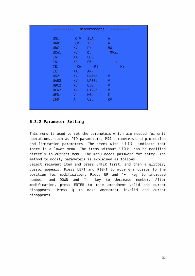
6.3.1 Measurement display
This menu shows all of the measured data and computed values on the screen.
Corresponding display variables:
UAB1, UBC1, UCA1: Measured PT three phase line voltages
UG1: Mean value of measured PT three phase line voltages
UAB2, UBC2, UCA2: Measured PT three phase line voltage on the instrument
UG2: Mean value of PT three phase line voltages on the instrument
IA,IB,IC: Three phase stator current
IG: Mean value of three phase stator current
ILA, ILB: Utility in three generator brushed excitation systems, with the operation mode of
double-cabinet current equalization. ILA is the excitation current of local cabinet and ILB is the
excitation current of the other one.
F0: Terminal voltage frequency of generator
F1: Frequency of excitation power supply
URAN: External superimposed test signal
UPSS: PSS output. When put in PSS, check this signal first. There is no impulse when this
signal is zero.
UFD: Rotor voltage
IFD: Rotor current
P: Active power
Q: Reactive power
COS: Power factor, which is rounded to three decimal places.
ARF: Trigger angle
U5V: 5V power supply
25

U12V: 12V power supply
H0: The percentage of heat productivity
US: Voltage in the power system side
---------- Measurements ---------
UG1: K V ILA: A
UAB1: KV ILB A
UBC1: KV P: MW
UCA1: KV Q: MVar
IG: KA COS
IA: KA F0: Hz
IB: KA F1: Hz
IC: KA ARF
UG2: KV URAN: V
UAB2: KV UPSS: V
UBC2: KV U5V: V
UCA2: KV U12V: V
UFD: V H0: %
IFD: A US: KV
6.3.2 Parameter Setting
This menu is used to set the parameters which are needed for unit operations, such as PID
parameters, PSS parameters and protection and limitation parameters. The items with “》》》” indicate that there is a lower menu. The items without “》》》” can be modified directly in current menu. The menu needs password for entry. The method to modify parameters is explained as
follows:
Select relevant item and press ENTER first, and then a glittery cursor appears. Press LEFT and
RIGHT to move the cursor to the position for modification. Press UP and “+” key to increase
number, and DOWN and “-” key to decrease number. After modification, press ENTER to make
amendment valid and cursor disappears. Press Q to make amendment invalid and cursor
disappears.
26

------- Para Setup------
AUTO PID 》》》 MAN PID 》》》 PSS Para 》》》 UEL Para 》》》 MAXIF1 VAL 2.0 DLY IF MAX 10 S Max If
2 VAL 2.2 V/Hz VAL 1.15 Q_droop +/- Q_droop VAL 5% Max Angle 150 Min Angle 20 Xq 0.7 Inc/dec 0.2%
6.3.2.1 Automatic PID
This menu is used to set the PID parameters which are needed for system operations graphically.
The method of modification is same to that described above.
6.3.2.2 Manual PID
This menu is used to set the PID parameters which are needed for manual operations.
------ - AUTO PID PARA ------
_
T1= 0.94 S T3= 0.5S KP=12T2= 9.4S T4= 0.05S b=0.02
b
27

6.3.2.3 PSS Parameters
Display the PSS transformer function and relative parameters graphically.
----- MAN PID PARA -------
ST
ST
ST
STK P
4
3
2
1
1
1
1
1
T1= 0.8S T3=2.0 S KP=5T2= 8.0S T4= 2.0 S
---- P S S PARA -----
9 10W +
11 12,13 14-22P
24-27
Tw1=0.15 Tw2=0.25 Ks2=1.00 T5=0.15 T6=0.25 T7=1.00T8 =0.15 T9=0.25 M=4KS1=100 T1=0.13 T2=0.22T3=0.08 T4=0.05 Ks3=1.00
Ks3
28

6.3.2.4 Under-Excited Limit
A: Point A of under-excited limit
B: Point B of under-excited limit
K: The proportion factor of under-excited loop
Ti: The time constant of under-excited loop
6.3.2.4 Other Parameters Explanation
Reinforced exciting multiple: used to set the max permitted excitation current. When the
excitation current reaches the preset reinforced exciting multiple, the regulator strongly cuts down
and restricts the excitation current under the preset multiple.
Reinforced exciting time: used to set the max permitted reinforced excitation time when the
excitation current reaches the preset reinforced excitation multiple.
Instant over-excitation: used to set the protection action value for instant over excitation. 1.5
second time delay after excitation current reaches this value, cut off the regulator at once.
V/Hz Multiple: used to set the V/Hz protection value. Setting range is from 1.00 to 1.50
The polarity of reactive power adjusting characteristics: it can be set to positive or negative
reactive power adjusting characteristics according to unit conditions.
The coefficient of reactive power adjusting characteristics: it can be set in the range from 0%
to 15% with 0.1% step.
Max α angle: used to set the maximal limit value of PID output. Generally, 150º for fully
controlled bridge and 170º for semi-controlled bridge.
Min α angle: used to set the minimal limit value of PID output. Generally, 15º for fully controlled
bridge and 50º for semi-controlled bridge.
Quadrature axis reactance: a parameter for PSS computation.
Increasing/decreasing rate: used to set the voltage change rate for the increasing and decreasing
operations. Setting range is from 0.2% to 2% UGN/s.
------- UEL LIMITER ----------- Q
B P
A
A:(0,200.2Mvar) B:(300.3MW,0)K:1.0 Ti: 2.55S
29

6.3.3 Protection Withdrawal
Set the withdrawal switch of protection terms in this menu. Need password for entry. Notice:
select the corresponding menu first, and then press ENTER to get into the modification state while
a glittery cursor appears. Press UP and DOWN to change the withdrawal state. Press ENTER to
make the amendment valid and the cursor disappears at the same time. Press Q to ignore the
amendment and the cursor disappears.
------- PTOTECTOR ON/OFF -----------
PT BRK ON/OFF V/HZ L ON/OFF UEL ON/OFF OEL: ON/OFF PUS MON ON/OFF SELFCHK ON/OFF TRIP ECB N/OFF OWN EXT ON/OFF OTH EXT ON/OFF SPARE ON/OFF SCR MON ON/OFF SPARE ON/OFF SPARE ON/OFF SPARE ON/OFF
6.3.4 Switching input status
The switching input status display can totally show 20 real time state variables. The last five lines
need to scroll the screen. Test method (switching input variable from the switching variable input
board): add 24V2 power supply on the back terminal in term to observe the change of
corresponding switching input variable. It will display closed while the signal is valid and open
while the signal is invalid.
Notice: among all of the switching input variables, only De-excitation switch and (current
equalization) operation are required to be normally closed. It will display open while add
24V2 power supply to these two switches, and closed with no signal added.
30

-------- DI Status --------- ECB : ON/OFF Soft Start: ON/OFF
OTH EXT DI ON/OFF 95%SPEED:N/OFF#1 fault: ON/OFF #2 fault: ON/OFF #3 Fault: ON/OFF PSS : ON/OFF CH Enable ON/OFF CH Active: ON/OFF AUTO mode : ON/OFF INC ON/OFF DEC : ON/OFF Q_CTRL ON/OFF COS_CTRL ON/OF DI_SELFEXT ON/OFF OTH_24V2 ON/OFF OWN_24V1 ON/OFF OWN_24V2 ON/OFF MBK ON/OFF SPARE ON/OFF SPARE ON/OFF
6.3.5 Drive Test
The switching values are output constrainedly in the drive test. Notice: the menu is only valid in
the halt state (when the de-excitation switch is in the open position). The menu can be access
without password.
Test method: select the item to be test first. Press ENTER and a glittery cursor appear. Press UP
and DOWN to change the switching state and then press ENTER to confirm. Press Q to keep the
corresponding switching state, and test whether the bit of the switching output in back terminal is
changed. While each limit and protection acts, the channel fault indication on the regulator panel
will be lighted. Only if all of the limit and protect test is canceled, the channel fault indication will
be reverted.
-------- DO TEST -------- ON Auto ON/OFF ON MAN ON/OFF ON PSS ON/OFF ON Q_CTRL ON/OFF ON COS_CTRL ON/OFF PT_FAULT ON/OFF V/HZ LIMIT ON/OFF OEL FAULT ON/OFF UEL ON/OFF SELF_CHK ON/OFF SCR fault ON/OFF PUS lose ON/OFF SPARE ON/OFF TRIP ON/OFF OTH_EXT ON/OFF OWN_EXT ON/OFF
6.3.6 System TestStep response test can be implemented in this interface, and the waveform of the selected variable
also can be shown in the form of norm value. Press LEFT and RIGHT to select the corresponding
menu. Press ENTER to modify the corresponding variable. Step variable can be modified with a
deviation of 20%. Secondly, set the hold time of step signal with a range from 0 second to 15
seconds and a minimal resolution of 0.1 second.
Select START menu and then press ENTER to output step variable. Menu display is stopped until
31
20 seconds record time is completed, and then the menu renews to display START. Press ENTER
to cancel step variable once some abnormal situations occur in the system and the menu display
get back to START.
After the test, select WAVE menu, and then press ENTER to choose the record variables to be
shown. Press UP and DOWN to change current record variable to display, including totally 12
waveforms: UG1, UG2, IG, UFD, IFD, ILA, ILB, P, Q, , UGREF, IFREF. Press ENTER and
then a vernier appears. The time and current amplitude of corresponding point is displayed on the
right upper screen. Press LEFT and RIGHT to move slowly. Press DOWN to move right fast and
UP to move left fast. Press Q to quit the menu step by step. The test interface need password for
entry.
6.3.7 Fault Recall
Fault status and the data in the moment faults occur can be displayed in the menu, including action
time (in millisecond precise), action type and action value. Action value are important collected
values of analog variable and computation values in the moment faults occurred, such as overheat
cumulative value H0, the definition and computation method of which is described in Chapter 5 in
detail. For power-fail storage, the record data is saved to serial EEPROM with 20 groups of this
data totally. Press UP and DOWN to scroll.
WAVE:UG1 --------- System Test --------
1.0pu (0.9pu,5.0 S)
20S
STEP:±10% TIME:15S START/STOP
32

-------- FAULT Recall ---------
2003-8-20 16:30:12:150 1/20Type OELFAULT value:Ug1: KV Ug2: KVUfd: V Ifd AP1: MW Q1: MVarARF: F0: MvarUGR: KV IFR: AILB: A ILA AU12V: V U5V: V
H0: 100 % COS:
6.3.8 Fault Waveform
As the system test, the waveform display can record four sets of waveform. After entering the
menu, select NUM menu automatically, and the glittery cursor appear. Press UP and DOWN to
select the set to be observed. The record time and fault type of this waveform appear in the
undermost line. It’s same to the system test to observe the waveform after selecting WAVE menu.
6.3.9 Event Recording
Event Recording is used to record the change of important switching variable. The total number of
recording is 20 with the principle of FIFO. Press UP and DOWN to scroll. Meanwhile, indicate
whether it is from 0 to 1 or from 1 to 0.
WAVE: UG1-------- Fault Waveform ---------- (0.92pu,1.23s)
1.0pu
20S
NUM:1/4
Time:2003-12-12 12:20:34:123 Fault
33

--------- Event Record ---------
1、 2003-8-20 16:30:12:150 ECB 0→1
2、 2003-8-20 16:30:12:150 ECB 1→0
3、 2003-8-20 16:30:12:150 ECB 1→0
6.3.10 Accuracy Setting
The menu provides a function of software potentiometer to modify the difference between actual
measured value and displayed value. It needs password for entry.
Notice: it is set OK in the factory and generally no need to modify in field.
------ Accuracy Aadjust ------
UAB1: 1.000 UFD: 1.000UBC1: 1.000 IDF: 1.000UCA1: 1.000 URAN: 1.000IA: 1.000 AD16: 1.000IB: 1.000 ILB: 1.000IC: 1.000 ILA: 1.000UAB2: 1.000 U12V: 1.000UBC2: 1.000 U5V: 1.000UCA2: 1.000 P1: 1.000USA: 1.000 Q1: 1.000USB: 1.000 U1: 1.000USC: 1.000 U2: 1.000
6.3.11 Unit Parameters
The way to modify unit parameters is just as that above. No mistake with the input unit
parameters. Input the same value of rated exciting current to that of rated output current for
brushless exciting system.
34

----------- Unit Parameters ------------
Rated UG: 13.8 KVRated IG: KA
Rated UFD: A
Rated IFD: V
Rated No-load UFD0: V
Rated ILD: V
F_PWR Supply: 350 Hz
6.3.12 System Configuration
Baud rate 1 is the baud rate of RS232 communication while baud rate 2 is that of CAN
communication. DA1 and DA2 output are optional DA output of two channels. Channel
configuration can be set as single channel operation or dual channels operation. Operation mode
can be set as master cabinet, slave cabinet (double-cabinet current equalization) or primary stand-
by mode. Fault clearing can clear the recalled fault. Event clearing can clear the corresponding
event recording. This menu needs password for entry. Password setting can set a new password.
Furthermore, the menu also provides time correction function. Channel configuration: is used to
configure the channel as single or dual channels and the mutual check function between the
channels is latched while single channel is set. Operation mode: according to specific excitation
mode, the channel can be configured as master cabinet, slave cabinet and primary standby. For an
excitation regulator of double-cabinet current equalization mode, the setting value of slave cabinet
changes with the output current of the master cabinet, to attain the effect of double-cabinet current
equalization. Two channels are equivalent in the primary standby mode, one operating while the
other trail.
----- System Settings ------
Password: 9999 COM ID: 0001
Baud rate1 :9600 Baud rate2 : 40K
DA1 NUM: 0001 DA2 NUM: 0001CH SET: single/dual Mode: master/slave /PRI-STBY--------------------------------------------------------------Fault CLR OK Event CLR OKTime Set: 2003-8-21 16:30:12
35

6.3.13 Test Option
Test Enabling Signal:
After entering the menu, the test enabling signal is in the prohibition state. Press ENTER and
glittery cursor appears. Press UP and DOWN to change the signal to the permission state. Press
ENTER again to add the test signal to test signal add point. Press CANCEL to make amendment
invalid and cursor disappears. The test enabling signal is set to the prohibition state automatically
before exiting. The test signal add point is corresponding to the position where the test signal adds
in.
0 Voltage setting value
1-8 Reserved
9-27 PSS transform function add point (see in PSS block diagram)
Notice: the function can only be used in test. Test enabling signal must be forbidden in normal
operation.
Test type includes test with compensation, test without compensation and terminating state.
Set test type to test without compensation and PSS output to zero, and then test the characteristic
of PID segment. Set test type to test with compensation and PSS output to zero, and then test the
characteristic of PSS plus PID segment. Set test type to terminating state and PSS works normally.
Notice: quit PSS first to change test type. After that, observing the displayed measured UPSS
output, put PSS into operation until UPSS steady output near zero.
PSS limit is the proportion of PID output, less than 10% in general.
PSS input is the limit of corresponding PSS input. That is to put PSS into operation while the
generator active power reaches the rated active power proportion.
PSS quit is the limit of corresponding PSS. That is to quit PSS while the generator active power
reaches rated active power proportion.
----- Test Option ------
Test Enable: Enable/DisableTest signal NUM: 0-30Test type: with compensation/without compensation/ENDPSS limitation value: 1%-10%PSS switch in: 30%
PSS switch out: 20%
6.3.14 Other Test
If constant pilot angle output enable is changed to a permission state, controller outputs constant
pilot angle. It is not used commonly.
Constant pilot angle output is used to set the angle of constant output, which can be set between
the maximal and minimal pilot angle.
36

---- Other Test ------
Constant angle Enable: Enable/DisableConstant Angle SET: 150
6.4 Operation description
6.4.1 Local operation
Switch 1QK to “Shut off”.
Turn on regulator power switch 1QS, 2QS.
Put “remote/local” on “local”
Close switch 1KKA, 1KKB
Switch 3QK to “AUTO”, switch 1QK to channel A or Channel B, generator voltage
raise to 90% rated voltage in several seconds.
Operate INCREASE 5QK, generator voltage increase to rated voltage. Parallel with
power system.
6.4.2 Remote operation
6.4.2.1 Be sure that the status QK1,QK3 on the remote console and 1QK,3QK on the cabinet are
same before remote operation. Switch 2QK to “remote”. The others are same as local
operation.
Note: Be sure that the QK1, QK3 on the remote console and 1QK, 3QK on the cabinet are
same state before switch 2QK from “local” to “remote”. And be sure that the 1QK, 3QK on
the cabinet and QK1, QK3 on the remote console are same state before change over from
“remote” to “local”.
6.4.3 Normal Stop
Decrease generator reactive load to zero.
Deparallel generator.
Press decrease button, depress the voltage to lowest level.
Switch 1QK and QK1 to quit position, shut off switch 1KKA, 1KKB,1QS, 2QS , then
DVR-2000B is quit.
6.4.4 Others
6.5 Maintenance
The hardware of DVR are simple and credible, commonly it needn’t special maintenance.
When DVR is off, only be care for following:
6.5.1 Check the junction and terminal of the DVR.
6.5.2 Clean dust and foreign matter in the cabinet.
6.5.3 Check switch and indicator light.
6.5.4 Improve running environment, Increase natural life of the DVR.
6.5.5 Study theory of operation, the method and principle of function of component’s setting.
Thus can make properly regulation on time when working mode is changing.
6.6 Checking item
When DVR is serving, checking as following
37

6.6.1 Check the junction of cabinet according to the wiring drawing.
6.6.2 Check insulation: Test the insulation resistance between the terminal and the cabinet with
the megaohm meter, and record it.
6.6.3 Check power supply: Put on DC supply. Test all DC voltage in the terminal block, and
record.
6.6.4 Check digital input: Connect the terminal block of digital input with DC24V2, select the
position of operation switch in the cabinet, then read it on the LCD, check the validity and
record.
6.6.5 Check digital output: Open the digital output screen, change the digital output, Check the
light and indicator on the IOX and relay boards. Record the result.
6.6.6 Check simulant input: Input the AC voltage and current in the terminal block, check the
correspond value in the LCD.
6.6.7 Check pulse circuit: Power on DVR, connect a load to DVR, select manual mode, Check
pulse indicator light on PGC board and the output voltage waveform.
38