dvs 100 and dvs150 - extronmedia.extron.com/.../dvs100-150_manual_revc.pdf · dvs 100 and dvs150...
TRANSCRIPT
DVS 100 and DVS150Digital Video Scalers
68-459-01Printed in USA
This symbol is intended to alert the user of important operating and maintenance(servicing) instructions in the literature provided with the equipment.
This symbol is intended to alert the user of the presence of uninsulated dangerousvoltage within the product's enclosure that may present a risk of electric shock.
CautionRead Instructions • Read and understand all safety and operating instructions before using the
equipment.
Retain Instructions • The safety instructions should be kept for future reference.
Follow Warnings • Follow all warnings and instructions marked on the equipment or in the userinformation.
Avoid Attachments • Do not use tools or attachments that are not recommended by the equipmentmanufacturer because they may be hazardous.
WarningPower sources • This equipment should be operated only from the power source indicated on the
product. This equipment is intended to be used with a main power system with a grounded(neutral) conductor. The third (grounding) pin is a safety feature, do not attempt to bypass ordisable it.
Power disconnection • To remove power from the equipment safely, remove all power cords fromthe rear of the equipment, or the desktop power module (if detachable), or from the powersource receptacle (wall plug).
Power cord protection • Power cords should be routed so that they are not likely to be stepped on orpinched by items placed upon or against them.
Servicing • Refer all servicing to qualified service personnel. There are no user-serviceable partsinside. To prevent the risk of shock, do not attempt to service this equipment yourself becauseopening or removing covers may expose you to dangerous voltage or other hazards.
Slots and openings • If the equipment has slots or holes in the enclosure, these are provided toprevent overheating of sensitive components inside. These openings must never be blocked byother objects.
Lithium battery • There is a danger of explosion if battery is incorrectly replaced. Replace it only withthe same or equivalent type recommended by the manufacturer. Dispose of used batteriesaccording to the manufacturer's instructions.
Ce symbole sert à avertir l’utilisateur que la documentation fournie avec le matérielcontient des instructions importantes concernant l’exploitation et la maintenance(réparation).
Ce symbole sert à avertir l’utilisateur de la présence dans le boîtier de l’appareil de tensions dangereuses non isolées posant des risques d’électrocution.
AttentionLire les instructions• Prendre connaissance de toutes les consignes de sécurité et d’exploitation avant
d’utiliser le matériel.
Conserver les instructions• Ranger les consignes de sécurité afin de pouvoir les consulter à l’avenir.
Respecter les avertissements • Observer tous les avertissements et consignes marqués sur le matériel ouprésentés dans la documentation utilisateur.
Eviter les pièces de fixation • Ne pas utiliser de pièces de fixation ni d’outils non recommandés par lefabricant du matériel car cela risquerait de poser certains dangers.
AvertissementAlimentations• Ne faire fonctionner ce matériel qu’avec la source d’alimentation indiquée sur
l’appareil. Ce matériel doit être utilisé avec une alimentation principale comportant un fil deterre (neutre). Le troisième contact (de mise à la terre) constitue un dispositif de sécurité :n’essayez pas de la contourner ni de la désactiver.
Déconnexion de l’alimentation• Pour mettre le matériel hors tension sans danger, déconnectez tousles cordons d’alimentation de l’arrière de l’appareil ou du module d’alimentation de bureau (s’ilest amovible) ou encore de la prise secteur.
Protection du cordon d’alimentation • Acheminer les cordons d’alimentation de manière à ce quepersonne ne risque de marcher dessus et à ce qu’ils ne soient pas écrasés ou pincés par des objets.
Réparation-maintenance • Faire exécuter toutes les interventions de réparation-maintenance par untechnicien qualifié. Aucun des éléments internes ne peut être réparé par l’utilisateur. Afind’éviter tout danger d’électrocution, l’utilisateur ne doit pas essayer de procéder lui-même à cesopérations car l’ouverture ou le retrait des couvercles risquent de l’exposer à de hautes tensionset autres dangers.
Fentes et orifices • Si le boîtier de l’appareil comporte des fentes ou des orifices, ceux-ci servent àempêcher les composants internes sensibles de surchauffer. Ces ouvertures ne doivent jamaisêtre bloquées par des objets.
Lithium Batterie • Il a danger d'explosion s'll y a remplacment incorrect de la batterie. Remplaceruniquement avec une batterie du meme type ou d'un ype equivalent recommande par leconstructeur. Mettre au reut les batteries usagees conformement aux instructions du fabricant.
Safety Instructions • English
Consignes de Sécurité • Français
Precautions
Sicherheitsanleitungen • Deutsch
Este símbolo se utiliza para advertir al usuario sobre instrucciones importantes deoperación y mantenimiento (o cambio de partes) que se desean destacar en elcontenido de la documentación suministrada con los equipos.
Este símbolo se utiliza para advertir al usuario sobre la presencia de elementos convoltaje peligroso sin protección aislante, que puedan encontrarse dentro de la cajao alojamiento del producto, y que puedan representar riesgo de electrocución.
PrecaucionLeer las instrucciones • Leer y analizar todas las instrucciones de operación y seguridad, antes de usar
el equipo.
Conservar las instrucciones • Conservar las instrucciones de seguridad para futura consulta.
Obedecer las advertencias • Todas las advertencias e instrucciones marcadas en el equipo o en ladocumentación del usuario, deben ser obedecidas.
Evitar el uso de accesorios • No usar herramientas o accesorios que no sean especificamenterecomendados por el fabricante, ya que podrian implicar riesgos.
AdvertenciaAlimentación eléctrica • Este equipo debe conectarse únicamente a la fuente/tipo de alimentación
eléctrica indicada en el mismo. La alimentación eléctrica de este equipo debe provenir de unsistema de distribución general con conductor neutro a tierra. La tercera pata (puesta a tierra) esuna medida de seguridad, no puentearia ni eliminaria.
Desconexión de alimentación eléctrica • Para desconectar con seguridad la acometida dealimentación eléctrica al equipo, desenchufar todos los cables de alimentación en el panel traserodel equipo, o desenchufar el módulo de alimentación (si fuera independiente), o desenchufar elcable del receptáculo de la pared.
Protección del cables de alimentación • Los cables de alimentación eléctrica se deben instalar enlugares donde no sean pisados ni apretados por objetos que se puedan apoyar sobre ellos.
Reparaciones/mantenimiento • Solicitar siempre los servicios técnicos de personal calificado. En elinterior no hay partes a las que el usuario deba acceder. Para evitar riesgo de electrocución, nointentar personalmente la reparación/mantenimiento de este equipo, ya que al abrir o extraer lastapas puede quedar expuesto a voltajes peligrosos u otros riesgos.
Ranuras y aberturas • Si el equipo posee ranuras o orificios en su caja/alojamiento, es para evitar elsobrecalientamiento de componentes internos sensibles. Estas aberturas nunca se deben obstruircon otros objetos.
Batería de litio • Existe riesgo de explosión si esta batería se coloca en la posición incorrecta. Cambiaresta batería únicamente con el mismo tipo (o su equivalente) recomendado por el fabricante.Desachar las baterías usadas siguiendo las instrucciones del fabricante.
Instrucciones de seguridad • Español
Dieses Symbol soll dem Benutzer in der im Lieferumfang enthaltenenDokumentation besonders wichtige Hinweise zur Bedienung und Wartung(Instandhaltung) geben.
Dieses Symbol soll den Benutzer darauf aufmerksam machen, daß im Inneren desGehäuses dieses Produktes gefährliche Spannungen, die nicht isoliert sind unddie einen elektrischen Schock verursachen können, herrschen.
AchtungLesen der Anleitungen • Bevor Sie das Gerät zum ersten Mal verwenden, sollten Sie alle Sicherheits-und
Bedienungsanleitungen genau durchlesen und verstehen.
Aufbewahren der Anleitungen • Die Hinweise zur elektrischen Sicherheit des Produktes sollten Sieaufbewahren, damit Sie im Bedarfsfall darauf zurückgreifen können.
Befolgen der Warnhinweise • Befolgen Sie alle Warnhinweise und Anleitungen auf dem Gerät oder inder Benutzerdokumentation.
Keine Zusatzgeräte • Verwenden Sie keine Werkzeuge oder Zusatzgeräte, die nicht ausdrücklich vomHersteller empfohlen wurden, da diese eine Gefahrenquelle darstellen können.
VorsichtStromquellen • Dieses Gerät sollte nur über die auf dem Produkt angegebene Stromquelle betrieben
werden. Dieses Gerät wurde für eine Verwendung mit einer Hauptstromleitung mit einemgeerdeten (neutralen) Leiter konzipiert. Der dritte Kontakt ist für einen Erdanschluß, und stellteine Sicherheitsfunktion dar. Diese sollte nicht umgangen oder außer Betrieb gesetzt werden.
Stromunterbrechung • Um das Gerät auf sichere Weise vom Netz zu trennen, sollten Sie alleNetzkabel aus der Rückseite des Gerätes, aus der externen Stomversorgung (falls dies möglichist) oder aus der Wandsteckdose ziehen.
Schutz des Netzkabels • Netzkabel sollten stets so verlegt werden, daß sie nicht im Weg liegen undniemand darauf treten kann oder Objekte darauf- oder unmittelbar dagegengestellt werdenkönnen.
Wartung • Alle Wartungsmaßnahmen sollten nur von qualifiziertem Servicepersonal durchgeführtwerden. Die internen Komponenten des Gerätes sind wartungsfrei. Zur Vermeidung eineselektrischen Schocks versuchen Sie in keinem Fall, dieses Gerät selbst öffnen, da beim Entfernender Abdeckungen die Gefahr eines elektrischen Schlags und/oder andere Gefahren bestehen.
Schlitze und Öffnungen • Wenn das Gerät Schlitze oder Löcher im Gehäuse aufweist, dienen diesezur Vermeidung einer Überhitzung der empfindlichen Teile im Inneren. Diese Öffnungen dürfenniemals von anderen Objekten blockiert werden.
Litium-Batterie • Explosionsgefahr, falls die Batterie nicht richtig ersetzt wird. Ersetzen Sieverbrauchte Batterien nur durch den gleichen oder einen vergleichbaren Batterietyp, der auchvom Hersteller empfohlen wird. Entsorgen Sie verbrauchte Batterien bitte gemäß denHerstelleranweisungen.
Quick Start — DVS 100 and DVS 150
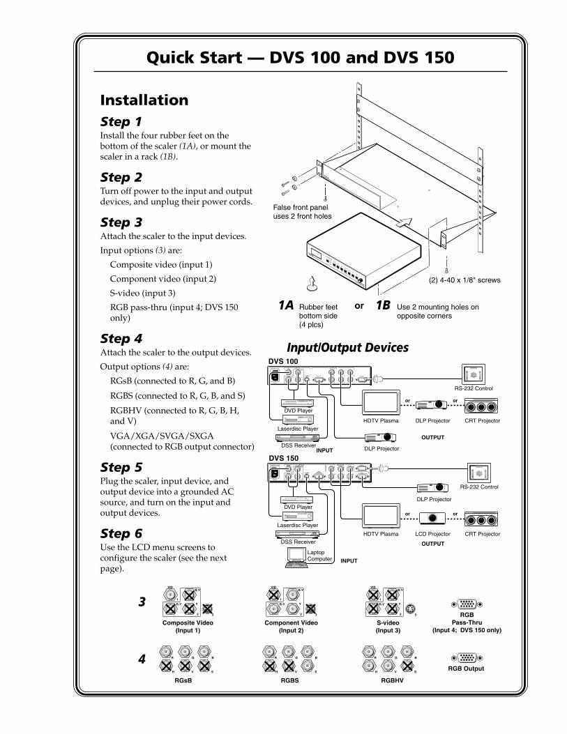
InstallationStep 1Install the four rubber feet on thebottom of the scaler (1A), or mount thescaler in a rack (1B).
Step 2Turn off power to the input and outputdevices, and unplug their power cords.
Step 3Attach the scaler to the input devices.
Input options (3) are:
Composite video (input 1)
Component video (input 2)
S-video (input 3)
RGB pass-thru (input 4; DVS 150only)
Step 4Attach the scaler to the output devices.
Output options (4) are:
RGsB (connected to R, G, and B)
RGBS (connected to R, G, B, and S)
RGBHV (connected to R, G, B, H,and V)
VGA/XGA/SVGA/SXGA(connected to RGB output connector)
Step 5Plug the scaler, input device, andoutput device into a grounded ACsource, and turn on the input andoutput devices.
Step 6Use the LCD menu screens toconfigure the scaler (see the nextpage).
Rubber feetbottom side(4 plcs)
(2) 4-40 x 1/8" screws
Use 2 mounting holes onopposite corners
False front paneluses 2 front holes
or1A 1B
RATE
V SHIFT
H SHIFT
CONTRAST
BRIT
TINT
COLOR
1
2
3
DVS 100
DIGITAL VIDEO SCALER
INPUT
Input/Output Devices
INPUTS
R-Y
50/60 Hz
100-240 VAC .3A MAX
1
2 3 4
Y
B-Y
H
R
V
G
S
BVIDEO REMOTE
RGBRGB
PASS-THRUS-VIDEO
OUTPUTS
RS-232 Control
RS-232 Control
INPUTS
R-Y
50/60 Hz
100-240V 0.1A
1
2 3
Y
B-Y
H
R
V
G
S
B
VID
REMOTERGB OUT
OUTPUTS
S-VIDEO
DVS 150
DVS 100
INPUT
OUTPUT
INPUT
OUTPUT
or or
CRT ProjectorLCD Projector
DLP Projector
HDTV Plasma
or or
CRT ProjectorDLP Projector
DLP Projector
HDTV Plasma
LaptopComputer
DVD Player
DSS Receiver
DVD Player
DSS Receiver
Laserdisc Player
Laserdisc Player
Composite Video(Input 1)
RGsB RGBS RGBHV
Component Video(Input 2)
S-video(Input 3)
RGB Output
RGBPass-Thru
(Input 4; DVS 150 only)
R-Y
1
2 3
Y
B-Y
H
R
V
G
S
B
H
R
V
G
S
B
H
R
V
G
S
B
VID
R-Y
1
2 3
Y
B-YVID
R-Y
1
2 3
Y
B-YVID
3
4

Quick Start — DVS 100 and DVS 150, cont’d
Configuring the ScalerConfiguring the scaler: Press the input and rate buttons simultaneously, and hold them for two
seconds.
Stepping through the LCD display menus: Press the input selection button.
Changing a selection: Turn the adjustment knob while the menu is displayed.
Exiting the menus: Press the input selection button while the Detail menu is displayed, or don’t pressany buttons or turn any knobs for eight seconds.
AUTOSW — Choose whether the DVS automatically selects the active input.On: The DVS selects the active input automatically. Off: You select the input manually.
TOPBLANK — Add or remove additional blanking lines at the top of the image.
BOTBLANK — Add or remove additional blanking lines at the bottom of the image.
H-SYNC — Change the polarity of the horizontal sync signal to allow any projector to distinguish theDVS 100 or DVS 150 input from a standard RGB input.+: Sets the horizontal sync polarity to positive. -: Sets the horizontal sync polarity to negative.
V-SYNC — Change the polarity of the vertical sync signal to allow any projector to distinguish theDVS 100 or DVS 150 input from a standard RGB input.+: Sets the vertical sync polarity to positive. -: Sets the vertical sync polarity to negative.
SOG — Set the sync output format.Yes: Sync on green (RGsB) output. No: RGBS or RGBHV output (based on unit cabling).
STILL — Enhance output for still or motion video.On: Enhanced image for still video and text. Off: Enhanced image for motion video.
DETAIL — Apply a filter to improve image detail.1: Low level of detail. 2: Medium level of detail. 3: High level of detail.
OperationChoosing the input source: Press the input selection button until the desired input LED lights.
If input 4 (RGB pass-through) of the DVS 150 is selected, you cannot make any of the followingadjustments.
Adjusting the image: Press the button for the adjustment, and rotate the adjustment knob until thedesired result is achieved.
Choosing the output rate: Press and hold the rate button for two seconds, and then rotate theadjustment knob until the desired rate appears in the LCD display. Options are:
640x480 (VGA), 60/75 Hz 848x480 (plasma), 60 Hz 1280x768 (plasma), 56 Hz 480p (HDTV)800x600 (SVGA), 60/75 Hz 852x480 (plasma), 60/75 Hz 1280x1024 (SXGA), 60 Hz 720p (HDTV)832x624 (Mac), 60/75 Hz 1024x768 (XGA), 60/75 Hz 1360x765 (plasma), 60 Hz 1080p (HDTV)
Activating freeze mode: Issue the RS-232 freeze mode command.
Deactivating freeze mode: Press the input selection button or issue an RS-232 command.
Restoring default picture control settings (active input): Press and hold the input selection button fortwo seconds.
Restoring all settings to factory defaults: Press and hold the input selection button while attachingthe AC power cord.
1-iDVS 100 and DVS 150 Table of Contents
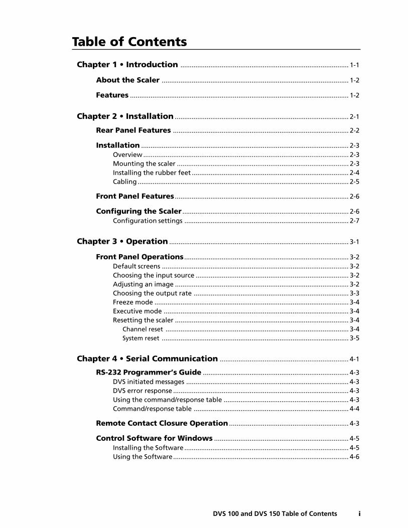
Chapter 1 • Introduction .......................................................................................... 1-1
About the Scaler .................................................................................................... 1-2
Features ..................................................................................................................... 1-2
Chapter 2 • Installation ............................................................................................. 2-1
Rear Panel Features .............................................................................................. 2-2
Installation ............................................................................................................... 2-3Overview .............................................................................................................. 2-3Mounting the scaler ............................................................................................ 2-3Installing the rubber feet .................................................................................... 2-4Cabling ................................................................................................................. 2-5
Front Panel Features ............................................................................................. 2-6
Configuring the Scaler ......................................................................................... 2-6Configuration settings ........................................................................................ 2-7
Chapter 3 • Operation ................................................................................................ 3-1
Front Panel Operations ........................................................................................ 3-2Default screens .................................................................................................... 3-2Choosing the input source .................................................................................. 3-2Adjusting an image ............................................................................................. 3-2Choosing the output rate ................................................................................... 3-3Freeze mode ........................................................................................................ 3-4Executive mode ................................................................................................... 3-4Resetting the scaler ............................................................................................. 3-4
Channel reset .................................................................................................. 3-4System reset .................................................................................................... 3-5
Chapter 4 • Serial Communication ..................................................................... 4-1
RS-232 Programmer’s Guide .............................................................................. 4-3DVS initiated messages ....................................................................................... 4-3DVS error response .............................................................................................. 4-3Using the command/response table ................................................................... 4-3Command/response table ................................................................................... 4-4
Remote Contact Closure Operation ................................................................ 4-3
Control Software for Windows ........................................................................ 4-5Installing the Software ........................................................................................ 4-5Using the Software.............................................................................................. 4-6
Table of Contents
Table of Contents, cont’d
ii DVS 100 and DVS 150 Table of Contents
Chapter 5 • Troubleshooting .................................................................................. 5-1
Operating Problems .............................................................................................. 5-2
Appendix A • Specifications .................................................................................. A-1
Appendix B • Reference Information ................................................................B-1
Part Numbers ..........................................................................................................B-2DVS 100 and DVS 150 part numbers ..................................................................B-2Related part numbers .........................................................................................B-2BNC cables ...........................................................................................................B-2
Glossary .....................................................................................................................B-3
68-459-01 CPrinted in the USA
04 00
1DVS 100 and DVS 150
Chapter One
Introduction
About the Scaler
Features
Introduction, cont’d
DVS 100 and DVS 150 Introduction1-2
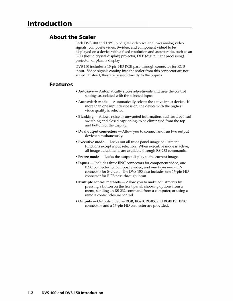
About the ScalerEach DVS 100 and DVS 150 digital video scaler allows analog videosignals (composite video, S-video, and component video) to bedisplayed on a device with a fixed resolution and aspect ratio, such as anLCD (liquid crystal display) projector, DLP (digital light processing)projector, or plasma display.
DVS 150 includes a 15-pin HD RGB pass-through connector for RGBinput. Video signals coming into the scaler from this connector are notscaled. Instead, they are passed directly to the ouputs.
Features• Autosave — Automatically stores adjustments and uses the control
settings associated with the selected input.
• Autoswitch mode — Automatically selects the active input device. Ifmore than one input device is on, the device with the highestvideo quality is selected.
• Blanking — Allows noise or unwanted information, such as tape headswitching and closed captioning, to be eliminated from the topand bottom of the display.
• Dual output connectors — Allow you to connect and run two outputdevices simultaneously.
• Executive mode — Locks out all front-panel image adjustmentfunctions except input selection. When executive mode is active,all image adjustments are available through RS-232 commands.
• Freeze mode — Locks the output display to the current image.
• Inputs — Includes three BNC connectors for component video, oneBNC connector for composite video, and one 4-pin mini-DINconnector for S-video. The DVS 150 also includes one 15-pin HDconnector for RGB pass-through input.
• Multiple control methods — Allow you to make adjustments bypressing a button on the front panel, choosing options from amenu, sending an RS-232 command from a computer, or using aremote contact closure control.
• Outputs — Outputs video as RGB, RGsB, RGBS, and RGBHV. BNCconnectors and a 15-pin HD connector are provided.
Introduction
1-3DVS 100 and DVS 150 Introduction
• Output resolutions — Supports the following output resolutions:
• 640 x 480 (VGA) at 60 or 75 Hz (Hertz)
• 800 x 600 (SVGA) at 60 or 75 Hz
• 832 x 624 (Macintosh) at 60 or 75 Hz
• 848 x 480 (plasma) at 60 Hz
• 852 x 480 (plasma) at 60 or 75 Hz
• 1024 x 768 (XGA) at 60 or 75 Hz
• 1280 x 768 (plasma) at 56 Hz
• 1280 x 1024 (SXGA) at 60 Hz
• 1360 x 765 (plasma) at 60 Hz
• 480p (HDTV)
• 720p (HDTV)
• 1080p (HDTV)
• Power supply — Includes an internal, 100-240VAC, 50/60 Hz, auto-switchable power supply.
• Precise image processing — Provides the latest in motion compensation,which produces motion images that are free of “jaggies”; a three-line adaptive comb filter, which eliminates chroma crawl; and a quadstandard decoder, which ensures compatibility with NTSC (NationalTelevision Standards Committee) 3.58, NTSC 4.43, SECAM(sequential couleur avec mémoire), and PAL (phase alternate line)video standards.
• Software-based configuration — Allows you to configure the scalerthrough menu controls, simplifying installation.
• Switchable sync polarities — Allow you to manually set thehorizontal and vertical sync polarities, to allow the output deviceto store DVS input as a unique input.
Introduction, cont’d
DVS 100 and DVS 150 Introduction1-4
2DVS 100 and DVS 150
Chapter Two
Installation
Rear Panel Features
Installation
Front Panel Features
Configuring the Scaler
Installation, cont’d
DVS 100 and DVS 150 Installation2-2
Rear Panel Features
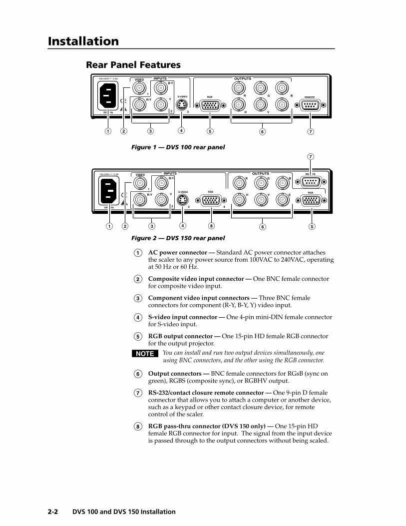
Figure 1 — DVS 100 rear panel
Figure 2 — DVS 150 rear panel
1 AC power connector — Standard AC power connector attachesthe scaler to any power source from 100VAC to 240VAC, operatingat 50 Hz or 60 Hz.
2 Composite video input connector — One BNC female connectorfor composite video input.
3 Component video input connectors — Three BNC femaleconnectors for component (R-Y, B-Y, Y) video input.
4 S-video input connector — One 4-pin mini-DIN female connectorfor S-video input.
5 RGB output connector — One 15-pin HD female RGB connectorfor the output projector.
You can install and run two output devices simultaneously, oneusing BNC connectors, and the other using the RGB connector.
6 Output connectors — BNC female connectors for RGsB (sync ongreen), RGBS (composite sync), or RGBHV output.
7 RS-232/contact closure remote connector — One 9-pin D femaleconnector that allows you to attach a computer or another device,such as a keypad or other contact closure device, for remotecontrol of the scaler.
8 RGB pass-thru connector (DVS 150 only) — One 15-pin HDfemale RGB connector for input. The signal from the input deviceis passed through to the output connectors without being scaled.
Installation
INPUTS
R-Y
50/60 Hz
100-240V 0.3A
1
2 3
Y
B-Y
H
R
V
G
S
B
VIDEO
REMOTERGB
OUTPUTS
S-VIDEO
1 2 3 4 5 6 7
INPUTS
R-Y
50/60 Hz
1
2 3 4
Y
B-Y
H
R
V
G
S
BVIDEO REMOTE
RGBRGBS-VIDEO
OUTPUTS
1 2 3 4 6
7
58
100-240V 0.3A

2-3DVS 100 and DVS 150 Installation
Installation
OverviewTo install and set up the DVS 100 or DVS 150, follow these basic steps:
1 If desired, mount the scaler in a rack (see “Mounting the scaler”below). Otherwise, install the rubber feet (see “Installing therubber feet” on page 2-4).
2 Turn off power to the input and output devices, and unplug thepower cables from them.
3 Attach the scaler to the input devices and the output devices. See“Cabling” on page 2-5.
4 Plug the scaler, input devices, and output devices into a groundedAC source.
5 Turn on the input and output devices.
6 Use the LCD menu screens to configure the scaler. See“Configuring the Scaler” on page 2-7.
7 The image from the input device should appear on the outputdevice. If it does not, double check steps 3 and 4 and makeadjustments as needed, and then see “Operating Problems” onpage 5-2.
Mounting the scalerEach DVS 100 and DVS 150 ships with four uninstalled rubber feet. Ifyou are going to rack mount the unit, do so before cabling it, and do notinstall the rubber feet. If you are not rack mounting the scaler, skip to“Installing the rubber feet” on page 2-4.
The DVS 100 or DVS 150 can be rack mounted using one side of anoptional 19” 1U Universal Rack Shelf (Extron part # 60-190-01).
To rack mount the scaler, do the following:
1. If rubber feet were previously installed on the bottom of the case,remove them.
2. Mount the scaler on the rack shelf as shown in figure 3. Use two4-40 x 1/8” screws in opposite (diagonal) corners to secure the caseto the shelf.
Installation, cont’d
DVS 100 and DVS 150 Installation2-4
Rubber FeetBottom Side (4 Plcs)
RATE
V SHIFT
H SHIFT
CONTRAST
BRIT
TINT
COLOR
1
2
3
DVS 100
DIGITAL VIDEO SCALER
INPUT
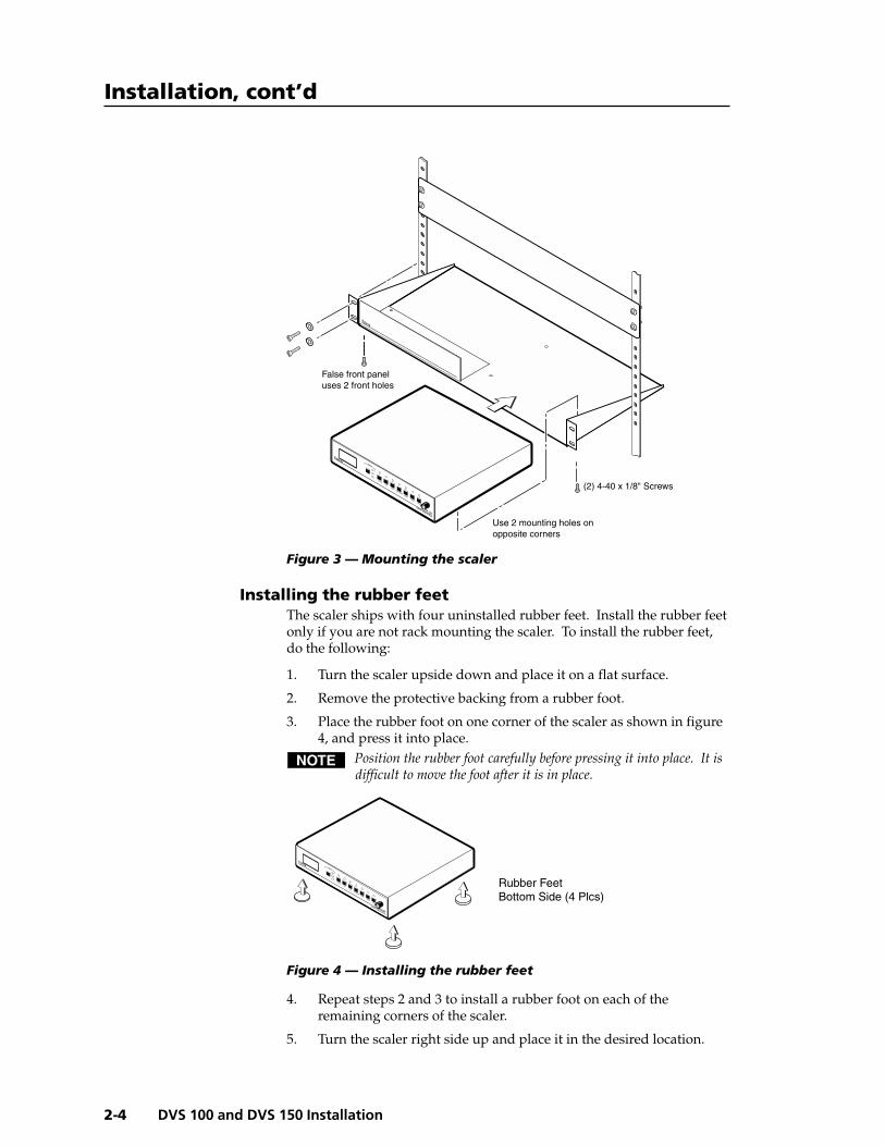
Figure 3 — Mounting the scaler
Installing the rubber feetThe scaler ships with four uninstalled rubber feet. Install the rubber feetonly if you are not rack mounting the scaler. To install the rubber feet,do the following:
1. Turn the scaler upside down and place it on a flat surface.
2. Remove the protective backing from a rubber foot.
3. Place the rubber foot on one corner of the scaler as shown in figure4, and press it into place.
Position the rubber foot carefully before pressing it into place. It isdifficult to move the foot after it is in place.
Figure 4 — Installing the rubber feet
4. Repeat steps 2 and 3 to install a rubber foot on each of theremaining corners of the scaler.
5. Turn the scaler right side up and place it in the desired location.
(2) 4-40 x 1/8" Screws
Use 2 mounting holes onopposite corners
False front paneluses 2 front holes
RATE
V SHIFT
H SHIFT
CONTRAST
BRIT
TINT
COLOR
1
2
3
DVS 100
DIGITAL VIDEO SCALER
INPUT
2-5DVS 100 and DVS 150 Installation
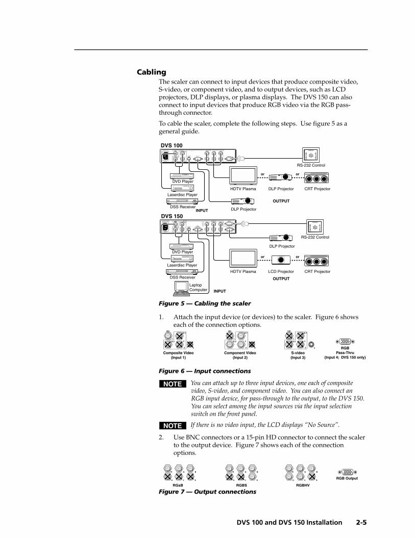
CablingThe scaler can connect to input devices that produce composite video,S-video, or component video, and to output devices, such as LCDprojectors, DLP displays, or plasma displays. The DVS 150 can alsoconnect to input devices that produce RGB video via the RGB pass-through connector.
To cable the scaler, complete the following steps. Use figure 5 as ageneral guide.
Figure 5 — Cabling the scaler
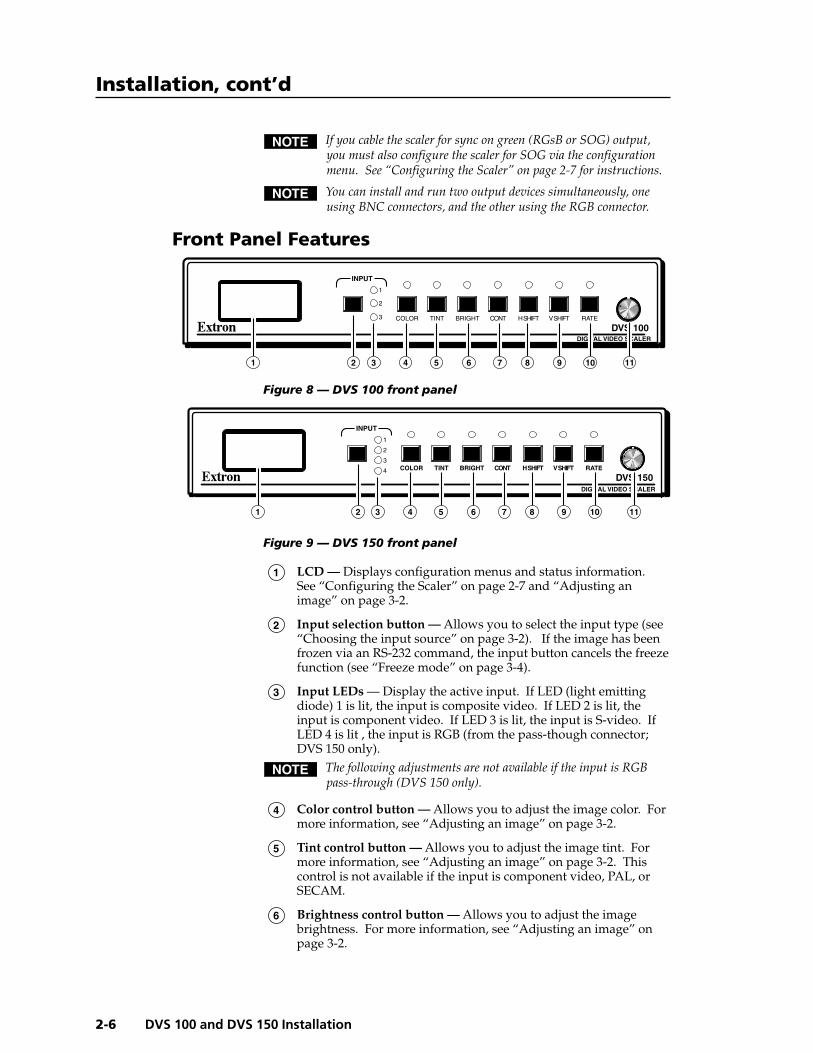
1. Attach the input device (or devices) to the scaler. Figure 6 showseach of the connection options.
Figure 6 — Input connections
You can attach up to three input devices, one each of compositevideo, S-video, and component video. You can also connect anRGB input device, for pass-through to the output, to the DVS 150.You can select among the input sources via the input selectionswitch on the front panel.
If there is no video input, the LCD displays “No Source”.
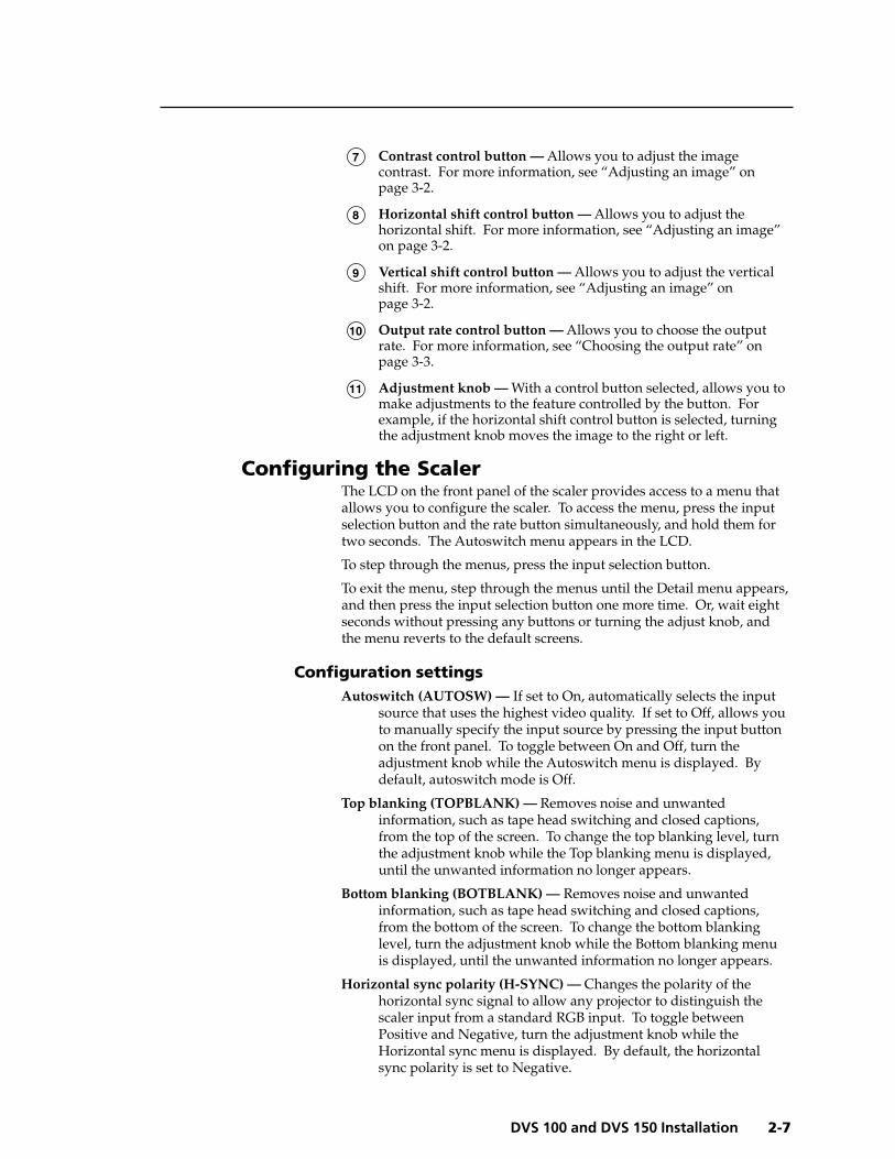
2. Use BNC connectors or a 15-pin HD connector to connect the scalerto the output device. Figure 7 shows each of the connectionoptions.
Figure 7 — Output connections
INPUTS
R-Y
50/60 Hz
100-240 VAC .3A MAX
1
2 3 4
Y
B-Y
H
R
V
G
S
BVIDEO REMOTE
RGBRGB
PASS-THRUS-VIDEO
OUTPUTS
RS-232 Control
RS-232 Control
INPUTS
R-Y
50/60 Hz
100-240V 0.1A
1
2 3
Y
B-Y
H
R
V
G
S
B
VID
REMOTERGB OUT
OUTPUTS
S-VIDEO
DVS 150
DVS 100
INPUT
OUTPUT
INPUT
OUTPUT
or or
CRT ProjectorLCD Projector
DLP Projector
HDTV Plasma
or or
CRT ProjectorDLP Projector
DLP Projector
HDTV Plasma
LaptopComputer
DVD Player
DSS Receiver
DVD Player
DSS Receiver
Laserdisc Player
Laserdisc Player
Composite Video(Input 1)
Component Video(Input 2)
S-video(Input 3)
RGBPass-Thru
(Input 4; DVS 150 only)
R-Y
1
2 3
Y
B-YVID
R-Y
1
2 3
Y
B-YVID
R-Y
1
2 3
Y
B-YVID
RGsB RGBS RGBHV
RGB OutputH
R
V
G
S
B
H
R
V
G
S
B
H
R
V
G
S
B
Installation, cont’d
DVS 100 and DVS 150 Installation2-6
If you cable the scaler for sync on green (RGsB or SOG) output,you must also configure the scaler for SOG via the configurationmenu. See “Configuring the Scaler” on page 2-7 for instructions.
You can install and run two output devices simultaneously, oneusing BNC connectors, and the other using the RGB connector.
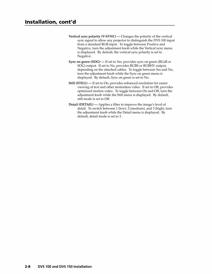
Front Panel Features
Figure 8 — DVS 100 front panel
Figure 9 — DVS 150 front panel
1 LCD — Displays configuration menus and status information.See “Configuring the Scaler” on page 2-7 and “Adjusting animage” on page 3-2.
2 Input selection button — Allows you to select the input type (see“Choosing the input source” on page 3-2). If the image has beenfrozen via an RS-232 command, the input button cancels the freezefunction (see “Freeze mode” on page 3-4).
3 Input LEDs — Display the active input. If LED (light emittingdiode) 1 is lit, the input is composite video. If LED 2 is lit, theinput is component video. If LED 3 is lit, the input is S-video. IfLED 4 is lit , the input is RGB (from the pass-though connector;DVS 150 only).
The following adjustments are not available if the input is RGBpass-through (DVS 150 only).
4 Color control button — Allows you to adjust the image color. Formore information, see “Adjusting an image” on page 3-2.
5 Tint control button — Allows you to adjust the image tint. Formore information, see “Adjusting an image” on page 3-2. Thiscontrol is not available if the input is component video, PAL, orSECAM.
6 Brightness control button — Allows you to adjust the imagebrightness. For more information, see “Adjusting an image” onpage 3-2.
RATEV SHIFTH SHIFTCONTBRIGHTTINTCOLOR
1
2
3
DVS 100DIGITAL VIDEO SCALER
INPUT
1 2 3 4 5 7 8 9 10 116
RATEV SHIFTH SHIFTCONTBRIGHTTINTCOLOR
1
2
3
4DVS 150
DIGITAL VIDEO SCALER
INPUT
1 2 3 4 5 6 7 8 9 10 11
2-7DVS 100 and DVS 150 Installation
7 Contrast control button — Allows you to adjust the imagecontrast. For more information, see “Adjusting an image” onpage 3-2.
8 Horizontal shift control button — Allows you to adjust thehorizontal shift. For more information, see “Adjusting an image”on page 3-2.
9 Vertical shift control button — Allows you to adjust the verticalshift. For more information, see “Adjusting an image” onpage 3-2.
10 Output rate control button — Allows you to choose the outputrate. For more information, see “Choosing the output rate” onpage 3-3.
11 Adjustment knob — With a control button selected, allows you tomake adjustments to the feature controlled by the button. Forexample, if the horizontal shift control button is selected, turningthe adjustment knob moves the image to the right or left.
Configuring the ScalerThe LCD on the front panel of the scaler provides access to a menu thatallows you to configure the scaler. To access the menu, press the inputselection button and the rate button simultaneously, and hold them fortwo seconds. The Autoswitch menu appears in the LCD.
To step through the menus, press the input selection button.
To exit the menu, step through the menus until the Detail menu appears,and then press the input selection button one more time. Or, wait eightseconds without pressing any buttons or turning the adjust knob, andthe menu reverts to the default screens.
Configuration settingsAutoswitch (AUTOSW) — If set to On, automatically selects the input
source that uses the highest video quality. If set to Off, allows youto manually specify the input source by pressing the input buttonon the front panel. To toggle between On and Off, turn theadjustment knob while the Autoswitch menu is displayed. Bydefault, autoswitch mode is Off.
Top blanking (TOPBLANK) — Removes noise and unwantedinformation, such as tape head switching and closed captions,from the top of the screen. To change the top blanking level, turnthe adjustment knob while the Top blanking menu is displayed,until the unwanted information no longer appears.
Bottom blanking (BOTBLANK) — Removes noise and unwantedinformation, such as tape head switching and closed captions,from the bottom of the screen. To change the bottom blankinglevel, turn the adjustment knob while the Bottom blanking menuis displayed, until the unwanted information no longer appears.
Horizontal sync polarity (H-SYNC) — Changes the polarity of thehorizontal sync signal to allow any projector to distinguish thescaler input from a standard RGB input. To toggle betweenPositive and Negative, turn the adjustment knob while theHorizontal sync menu is displayed. By default, the horizontalsync polarity is set to Negative.
Installation, cont’d
DVS 100 and DVS 150 Installation2-8
Vertical sync polarity (V-SYNC) — Changes the polarity of the verticalsync signal to allow any projector to distinguish the DVS 100 inputfrom a standard RGB input. To toggle between Positive andNegative, turn the adjustment knob while the Vertical sync menuis displayed. By default, the vertical sync polarity is set toNegative.
Sync on green (SOG) — If set to Yes, provides sync on green (RGsB orSOG) output. If set to No, provides RGBS or RGBHV output,depending on the attached cables. To toggle between Yes and No,turn the adjustment knob while the Sync on green menu isdisplayed. By default, Sync on green is set to No.
Still (STILL) — If set to On, provides enhanced resolution for easierviewing of text and other motionless video. If set to Off, providesoptimized motion video. To toggle between On and Off, turn theadjustment knob while the Still menu is displayed. By default,still mode is set to Off.
Detail (DETAIL) — Applies a filter to improve the image’s level ofdetail. To switch between 1 (low), 2 (medium), and 3 (high), turnthe adjustment knob while the Detail menu is displayed. Bydefault, detail mode is set to 3.

3DVS 100 and DVS 150
Chapter Three
Operation
Front Panel Operations

Operation, cont’d
DVS 100 and DVS 150 Operation3-2
Operation
Front Panel OperationsThe front panel includes an LCD screen that displays the current statusof the scaler and the scan rate of the current video input signal. You canalso use controls on the front panel to control the image display.
Diagrams of the front panels are shown on page 2-6.
Default screensBy default, the LCD toggles between two screens every four seconds.One screen displays the product name, and the other shows the outputresolution and frequency (figure 10 shows an example).
Figure 10 — Default screens
If no input signal is present, the LCD backlight turns off and the LCDtoggles between screens similar to those shown in figure 11.
Figure 11 — No signal present
Choosing the input sourceTo choose an input source, press the input selection button to togglethrough the inputs. The LED corresponding to the selected input lights:• Input LED 1 — Composite video
• Input LED 2 — Component video
• Input LED 3 — S-video
• Input LED 4 — RGB pass-through video (DVS 150 only)
When the button is released, the input changes and the LCD shows thecurrent input and signal type (see figure 12). The message appears for8 seconds, and then changes back to the default screens.
Figure 12 — Current input screens
If an RS-232 command was issued to activate the freeze function, tochange the input source you must press the input selection buttontwice. The first press unfreezes the image, and the second changesthe input source.
Adjusting an imageThe front panel controls allow you to make adjustments to the displayedimage.
To make an adjustment, do the following:
1. Push the control button that corresponds to the adjustment youwant to make. The LED above the pressed button lights, and,depending on the selected button, the LCD displays the currentlevel value for the adjustment.
2. Turn the adjustment knob until the desired adjustment isaccomplished. The LCD returns to the default screens, and theadjusted value is saved for future use by the active input, if you
1280 X1024 @60
EXTRONDVS 100
NoSource
EXTRONDVS 100
INPUT 2COMPNENT
INPUT 1CMPOSITE
INPUT 3S-VIDEO
INPUT 4RGB
3-3DVS 100 and DVS 150 Operation
press the same button again or if you stop turning the knob foreight seconds.
If an image control reaches its minimum, maximum, or default level, theLCD displays a screen similar to the screens shown in figure 13.
Figure 13 — Minimum, maximum, and default value screens
If input 4 (RGB pass-through) of the DVS 150 is selected, youcannot adjust the image through the scaler.
Color control button — Adjusts the color intensity.
Tint control button — Adjusts the amount of tint displayed. Thisadjustment is not available if the input is component video, PAL,or SECAM.
Brightness control button — Adjusts the amount or intensity of videolight produced on the screen, without regard to color.
Contrast control button — Adjusts the range of light and dark values ina picture, or the ratio between the maximum and the minimumbrightness values.
Horizontal shift control button — Shifts the image to the left and right.
Vertical shift control button — Shifts the image up and down.
Choosing the output rateIf input 4 (RGB pass-through) of the DVS 150 is selected, youcannot change the output rate through the scaler.
To choose the output rate, do the following:
1. Refer to the documentation that accompanied the display device todetermine its native mode (or sweet spot).
2. Press and hold the rate button on the scaler for two seconds. TheLED above the button lights, and the LCD displays the currentoutput resolution and frequency.
3. Turn the adjustment knob until the desired output rate appears inthe LCD and the image is displayed at the correct rate.
Available rates are:
• 640 x 480, 60 Hz • 640 x 480, 75 Hz
• 800 x 600, 60 Hz • 800 x 600, 75 Hz
• 832 x 624, 60 Hz • 832 x 624, 75 Hz
• 848 x 480, 60 Hz
• 852 x 480, 60 Hz • 852 x 480, 75 Hz
• 1024 x 768, 60 Hz • 1024 x 768, 75 Hz
• 1280 x 768, 56 Hz • 1280 x 1024, 60 Hz
• 1360 x 765, 60 Hz
• HDTV 480p
• HDTV 720p
• HDTV 1080p
COLORMax
COLORMin
COLORDefault
Operation, cont’d
DVS 100 and DVS 150 Operation3-4
Freeze modeFreeze mode locks the output display to the current image. Freeze mode
can be activated only by issuing an RS-232 command(see chapter 4 for more information). If freeze modeis activated, the LCD screen displays the messagedisplayed at the left.
If input 4 (RGB pass-through) of the DVS 150 is selected, youcannot activate freeze mode.
You can deactivate freeze mode in the following ways:
• By issuing another RS-232 command
• By pressing the input selection button
• Automatically, if the scaler is in autoswitch mode and the input sourcechanges.
Executive modeExecutive mode limits the number of operations available from the frontpanel. This is useful for situations in which many end users operate thescaler, and you want to prevent them from changing the adjustmentsyou have made.
To enable executive mode, press the horizontal shift and vertical shiftcontrol buttons simultaneously for two seconds. TheLCD displays the message at the left for eightseconds, and then changes back to the defaultscreens.
When executive mode is enabled, the only front panel button that can beused is the input selection button. If any other button is pressed, theLCD displays the same message for eight seconds, then changes back tothe default screens.
To disable executive mode, press the horizontal shift and vertical shiftcontrol buttons simultaneously for two seconds. TheLCD displays the message at the left for eightseconds, then changes back to the default screens.
Resetting the scalerYou can perform two types of reset:
• Channel reset restores the factory default picture control settings (color,tint, brightness, contrast, horizontal shift, and vertical shift) foronly the currently selected input.
If input 4 (RGB pass-through) of the DVS 150 is selected, youcannot perform a channel reset.
• System reset restores all factory default settings, including all picturecontrols for all inputs, the output rate, and all configurationoptions available from the LCD menu.
Channel resetTo perform a channel reset, press and hold the input selection button for
two seconds. The picture control settings for theactive input are reset to their factory default settings.The LCD displays a message similar to the one at theleft for four seconds, and then changes back to thedefault screens.
IMAGEFROZEN
X-MODEENABLED
X-MODEDISABLED
INPUT 1RESET
3-5DVS 100 and DVS 150 Operation
System resetTo perform a system reset, press and hold the input selection button
while attaching the AC power cord. The picturecontrol settings for all input sources, the output rates,and the configuration options are reset to their factorydefault settings. The LCD displays the message atthe left for four seconds, and then changes back to thedefault screens.
SYSTEMRESET

Operation, cont’d
DVS 100 and DVS 150 Operation3-6

4DVS 100 and DVS 150
Chapter Four
Serial Communication
RS-232 Programmer’s Guide
Remote Contact Closure Operation
Control Software for Windows
Serial Communication, cont’d
DVS 100 and DVS 150 Serial Communication4-2
Serial Communication
RS-232Control Cable
RS-232Control Cable
DVS 100
DVS 150
Computer Control
H
R
V
G
S
BREMOTE
OUTPUTS
H
R
V
G
S
B
REMOTE
RGB
OUTPUTS
Computer Control
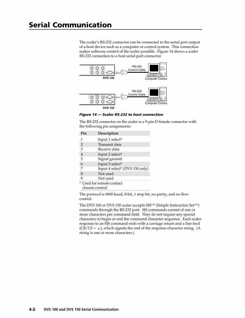
The scaler’s RS-232 connector can be connected to the serial port outputof a host device such as a computer or control system. This connectionmakes software control of the scaler possible. Figure 14 shows a scalerRS-232 connection to a host serial port connector.
Figure 14 — Scaler RS-232 to host connection
The RS-232 connector on the scaler is a 9-pin D female connector withthe following pin assignments:
Pin Description
1 Input 1 select*2 Transmit data3 Receive data4 Input 2 select*5 Signal ground6 Input 3 select*7 Input 4 select* (DVS 150 only)8 Not used9 Not used
* Used for remote contactclosure control
The protocol is 9600 baud, 8-bit, 1 stop bit, no parity, and no flowcontrol.
The DVS 100 or DVS 150 scaler accepts SIS™ (Simple Instruction Set™)commands through the RS-232 port. SIS commands consist of one ormore characters per command field. They do not require any specialcharacters to begin or end the command character sequence. Each scalerresponse to an SIS command ends with a carriage return and a line feed(CR/LF = ), which signals the end of the response character string. (Astring is one or more characters.)
4-3DVS 100 and DVS 150 Serial Communication
RS-232 Programmer’s Guide
DVS initiated messagesWhen a local event occurs, such as a front panel operation, the scalerresponds by sending a message to the host. The DVS-initiated messagesare listed below (underlined).
(C) Copyright 1999, Extron Electronics, DVS xxx, Vx.x
The copyright message is initiated by the scaler when it is first poweredon. DVS xxx is the scaler model, and Vx.xx is the firmware versionnumber.
Reconfig
The Reconfig message is initiated by the scaler when a new input isselected or when any image adjustment is made.
The scaler does not expect a response from the host, but, for example,the host program might request a new status.
DVS error responseWhen the scaler receives an SIS command and determines that it isvalid, it performs the command and sends a response back to the hostdevice. If the scaler is unable to perform the command because thecommand is invalid or contains invalid parameters, the scaler returns anerror response to the host. The error response codes are:
E01 — Invalid input channel number (too large)E09 — Invalid function number (too large)E10 — Invalid commandE13 — Invalid value (out of range)
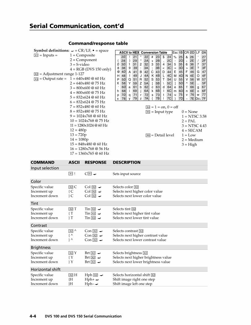
Using the command/response tableThe command/response table is shown on the next page. Lower casecharacters are acceptable in the command field only where indicated.Symbols are used throughout the table to represent variables in thecommand/response fields. Symbol definitions are shown at thebeginning of the table, as is an ASCII-to-hexadecimal (HEX) conversiontable. Command and response examples are shown throughout thetable.
Screen adjustment commands are not available if input 4 is selected(DVS 150 only).
Remote Contact Closure OperationThe RS-232 connector provides a way to control the scaler from a remotecontact closure device. This is made possible by using pins that are notnormally used by the RS-232 interface. The contact closure pinassignments are shown in the table on page 4-2.
To select a different input number through the RS-232 connector,momentarily short the pin for the desired input number (#) to the signalground (pin 5). To force one of the inputs to be selected continuously,leave the short to signal ground in place. This will override any frontpanel input selection.
Serial Communication, cont’d
DVS 100 and DVS 150 Serial Communication4-4
Command/response table
Symbol definitions: = CR/LF, • = space = Inputs = 1 = Composite
2 = Component3 = S-video4 = RGB (DVS 150 only)
= Adjustment range 1-127 = Output rate = 1 = 640x480 @ 60 Hz
2 = 640x480 @ 75 Hz3 = 800x600 @ 60 Hz4 = 800x600 @ 75 Hz5 = 832x624 @ 60 Hz6 = 832x624 @ 75 Hz7 = 852x480 @ 60 Hz8 = 852x480 @ 75 Hz9 = 1024x768 @ 60 Hz10 = 1024x768 @ 75 Hz11 = 1280x1024 @ 60 Hz12 = 480p13 = 720p14 = 1080p15 = 848x480 @ 60 Hz16 = 1280x768 @ 56 Hz17 = 1360x765 @ 60 Hz
= 1 = on, 0 = off = Input type 0 = None
1 = NTSC 3.582 = PAL3 = NTSC 4.434 = SECAM
= Detail level 1 = Low2 = Medium3 = High
COMMAND ASCII RESPONSE DESCRIPTIONInput selection
! C Sets input source
ColorSpecific value C Col Selects color Increment up { C Col Selects next higher color valueIncrement down } C Col Selects next lower color value
TintSpecific value T Tin Selects tint Increment up { T Tin Selects next higher tint valueIncrement down } T Tin Selects next lower tint value
ContrastSpecific value ^ Con Selects contrast Increment up { ^ Con Selects next higher contrast valueIncrement down } ^ Con Selects next lower contrast value
BrightnessSpecific value Y Brt Selects brightness Increment up { Y Brt Selects next higher brightness valueIncrement down } Y Brt Selects next lower brightness value
Horizontal shiftSpecific value H Hph Selects horizontal shift Increment up {H Hph+ Shift image right one stepIncrement down }H Hph– Shift image left one step
ASCII to HEX Conversion Table
•
4-5DVS 100 and DVS 150 Serial Communication
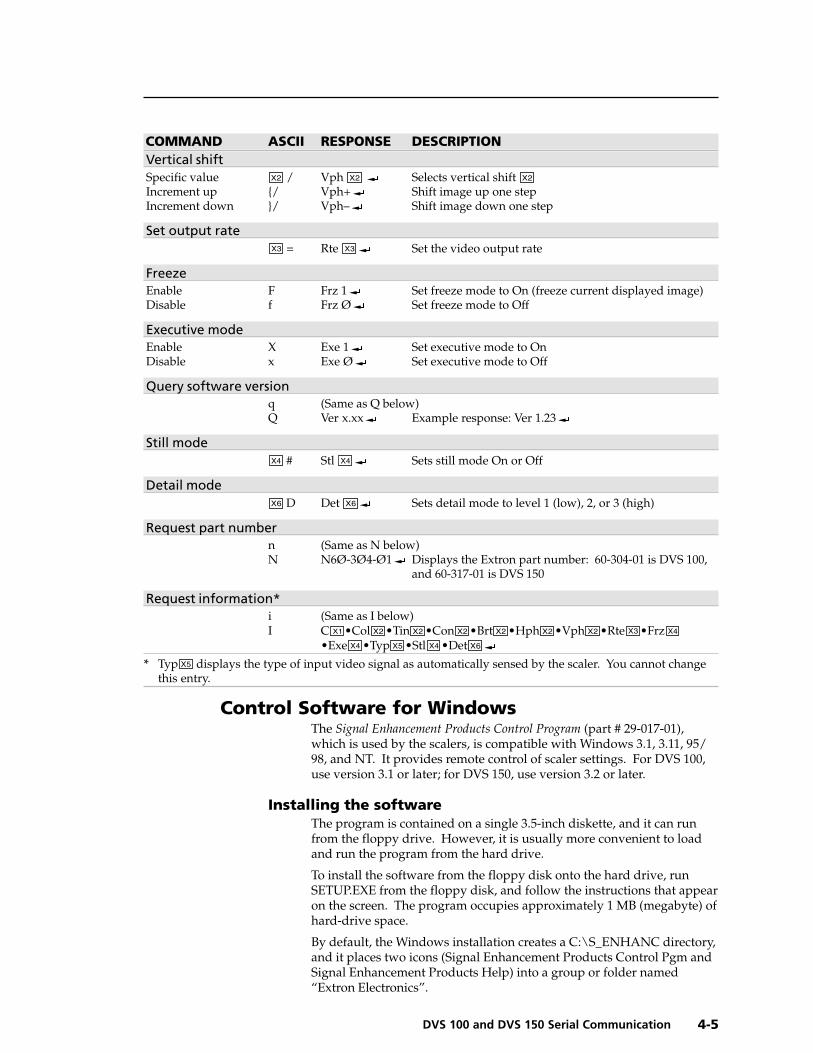
COMMAND ASCII RESPONSE DESCRIPTIONVertical shiftSpecific value / Vph Selects vertical shift Increment up {/ Vph+ Shift image up one stepIncrement down }/ Vph– Shift image down one step
Set output rate = Rte Set the video output rate
FreezeEnable F Frz 1 Set freeze mode to On (freeze current displayed image)Disable f Frz Ø Set freeze mode to Off
Executive modeEnable X Exe 1 Set executive mode to OnDisable x Exe Ø Set executive mode to Off
Query software versionq (Same as Q below)Q Ver x.xx Example response: Ver 1.23
Still mode # Stl Sets still mode On or Off
Detail mode D Det Sets detail mode to level 1 (low), 2, or 3 (high)
Request part numbern (Same as N below)N N6Ø-3Ø4-Ø1 Displays the Extron part number: 60-304-01 is DVS 100,
and 60-317-01 is DVS 150
Request information*i (Same as I below)I C •Col •Tin •Con •Brt •Hph •Vph •Rte •Frz
•Exe •Typ •Stl •Det
* Typ displays the type of input video signal as automatically sensed by the scaler. You cannot changethis entry.
Control Software for WindowsThe Signal Enhancement Products Control Program (part # 29-017-01),which is used by the scalers, is compatible with Windows 3.1, 3.11, 95/98, and NT. It provides remote control of scaler settings. For DVS 100,use version 3.1 or later; for DVS 150, use version 3.2 or later.
Installing the softwareThe program is contained on a single 3.5-inch diskette, and it can runfrom the floppy drive. However, it is usually more convenient to loadand run the program from the hard drive.
To install the software from the floppy disk onto the hard drive, runSETUP.EXE from the floppy disk, and follow the instructions that appearon the screen. The program occupies approximately 1 MB (megabyte) ofhard-drive space.
By default, the Windows installation creates a C:\S_ENHANC directory,and it places two icons (Signal Enhancement Products Control Pgm andSignal Enhancement Products Help) into a group or folder named“Extron Electronics”.
Serial Communication, cont’d
DVS 100 and DVS 150 Serial Communication4-6
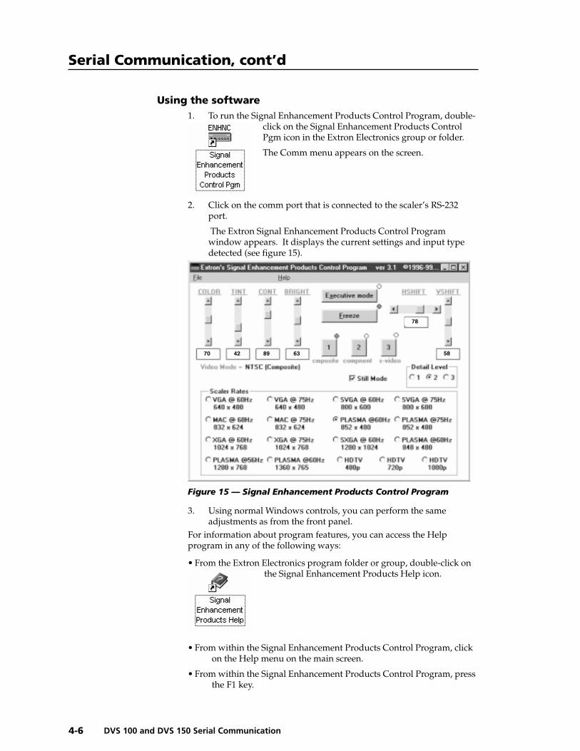
Using the software1. To run the Signal Enhancement Products Control Program, double-
click on the Signal Enhancement Products ControlPgm icon in the Extron Electronics group or folder.
The Comm menu appears on the screen.
2. Click on the comm port that is connected to the scaler’s RS-232port.
The Extron Signal Enhancement Products Control Programwindow appears. It displays the current settings and input typedetected (see figure 15).
Figure 15 — Signal Enhancement Products Control Program
3. Using normal Windows controls, you can perform the sameadjustments as from the front panel.
For information about program features, you can access the Helpprogram in any of the following ways:
• From the Extron Electronics program folder or group, double-click onthe Signal Enhancement Products Help icon.
• From within the Signal Enhancement Products Control Program, clickon the Help menu on the main screen.
• From within the Signal Enhancement Products Control Program, pressthe F1 key.
70 42 89 63
78
58
5DVS 100 and DVS 150
Chapter Five
Troubleshooting
Operating Problems

Troubleshooting, cont’d
DVS 100 and DVS 150 Troubleshooting5-2
This section gives recommendations on what to do if you have problemsoperating the DVS 100 or DVS 150, and it provides examples anddescriptions for some image problems you might encounter.
Following are some tips to help you in troubleshooting.
1. Some symptoms may resemble others, so you may want to lookthrough all of the examples before attacking the problem.
2. Be prepared to backtrack in case the action taken doesn’t solve theproblem.
3. It may help to keep notes and sketches in case the troubleshootingprocess gets lengthy. This will also give you something todiscuss if you call for technical support.
4. Try simplifying the system by eliminating components that mayhave introduced the problem or made it more complicated.
5. For sync-related problems: Portable digital projectors are designedto operate close to the video source. Sync problems may resultfrom using long cables or from improper termination. A syncadapter, such as Extron’s ASTA (active sync termination adapter),may help solve these problems.
6. For LCD and DLP projectors and plasma displays: In addition to thesync-related information above, check the user’s manual thatcame with the projector for troubleshooting tips, as well as forsettings and adjustments. Each manufacturer may have its ownterms, so look for terms like “auto setup”, “auto sync”, “pixelphase”, and “tracking”.
Operating ProblemsThe table below shows some common operating problems and theirsolutions.
Problem Cause Solution
No image The input signal is Attach an input device that isappears. incompatible. compatible with NTSC 3.58,
NTSC 4.43, PAL, or SECAM.Freeze mode was Deactivate freeze modeentered when the (page 3-4).image was black.The scaled output Change the scaled output to arate is too high for compatible resolutionthe display. (page 3-3).
The image is Freeze mode is on. Deactivate freeze modefrozen. (page 3-4). If that does not
work, unplug the power cordfrom the scaler, then plug itback in.
The image is The scaled output Change the scaled output to aflashing. rate is too high for compatible resolution
the display. (page 3-3).
Inputs cannot Autoswitch is Turn off autoswitch (page 2-7).be switched. turned on.
Troubleshooting

5-3DVS 100 and DVS 150 Troubleshooting
Problem Cause Solution
Picture controls Input 4 is selected Switch to input 1–3. Input 4 isare not active. (DVS 150 only). pass-through only (page 1-2).
The image is The unit is Turn off sync on greengreen. configured for (page 2-8).
sync on green.
The image The detail level Change the detail levelis too soft. needs to be changed. (page 2-8).

Troubleshooting, cont’d
DVS 100 and DVS 150 Troubleshooting5-4
ADVS 100 and DVS 150
Appendix A
Specifications
A-2 DVS 100 and DVS 150 Specifications
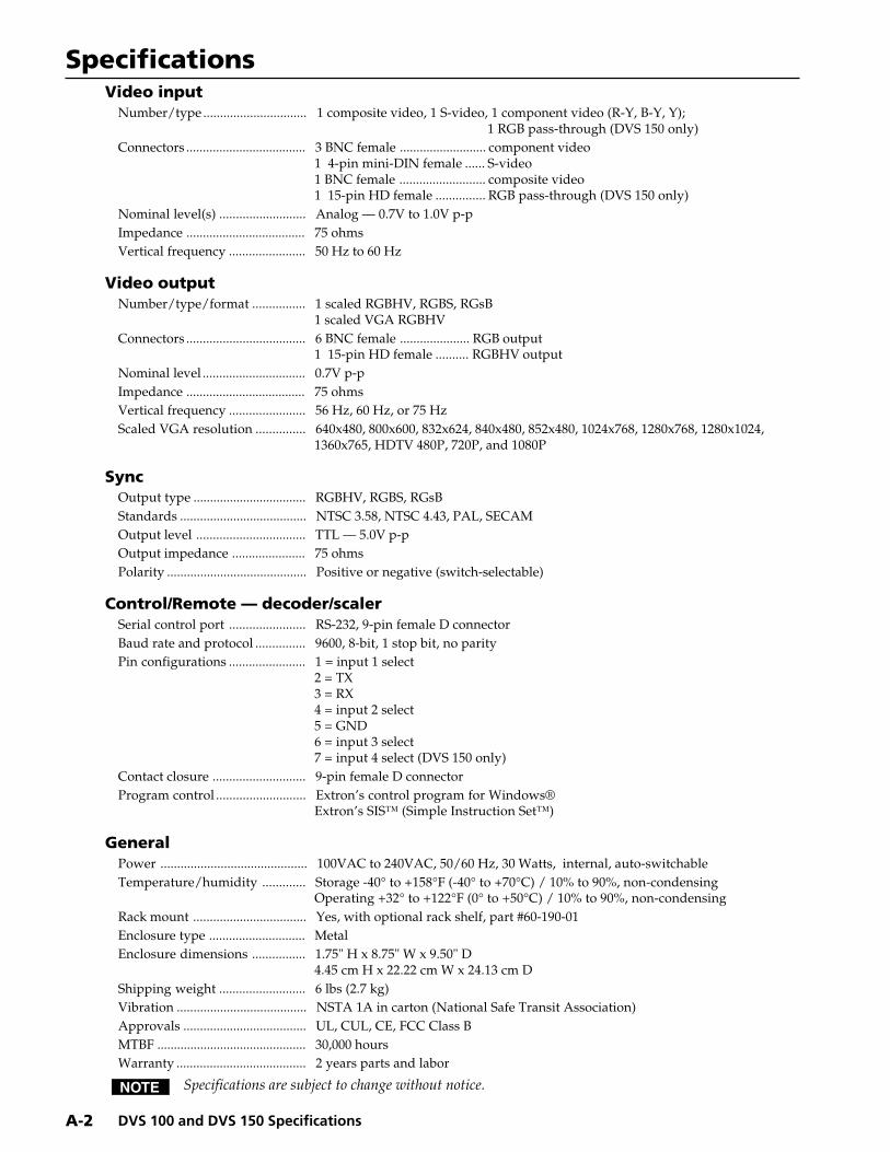
SpecificationsVideo input
Number/type ............................... 1 composite video, 1 S-video, 1 component video (R-Y, B-Y, Y);1 RGB pass-through (DVS 150 only)
Connectors .................................... 3 BNC female .......................... component video1 4-pin mini-DIN female ...... S-video1 BNC female .......................... composite video1 15-pin HD female ............... RGB pass-through (DVS 150 only)
Nominal level(s) .......................... Analog — 0.7V to 1.0V p-pImpedance .................................... 75 ohmsVertical frequency ....................... 50 Hz to 60 Hz
Video outputNumber/type/format ................ 1 scaled RGBHV, RGBS, RGsB
1 scaled VGA RGBHVConnectors .................................... 6 BNC female ..................... RGB output
1 15-pin HD female .......... RGBHV outputNominal level ............................... 0.7V p-pImpedance .................................... 75 ohmsVertical frequency ....................... 56 Hz, 60 Hz, or 75 HzScaled VGA resolution ............... 640x480, 800x600, 832x624, 840x480, 852x480, 1024x768, 1280x768, 1280x1024,
1360x765, HDTV 480P, 720P, and 1080P
SyncOutput type .................................. RGBHV, RGBS, RGsBStandards ...................................... NTSC 3.58, NTSC 4.43, PAL, SECAMOutput level ................................. TTL — 5.0V p-pOutput impedance ...................... 75 ohmsPolarity .......................................... Positive or negative (switch-selectable)
Control/Remote — decoder/scalerSerial control port ....................... RS-232, 9-pin female D connectorBaud rate and protocol ............... 9600, 8-bit, 1 stop bit, no parityPin configurations ....................... 1 = input 1 select
2 = TX3 = RX4 = input 2 select5 = GND6 = input 3 select7 = input 4 select (DVS 150 only)
Contact closure ............................ 9-pin female D connectorProgram control ........................... Extron’s control program for Windows®
Extron’s SIS™ (Simple Instruction Set™)
GeneralPower ............................................ 100VAC to 240VAC, 50/60 Hz, 30 Watts, internal, auto-switchableTemperature/humidity ............. Storage -40° to +158°F (-40° to +70°C) / 10% to 90%, non-condensing
Operating +32° to +122°F (0° to +50°C) / 10% to 90%, non-condensingRack mount .................................. Yes, with optional rack shelf, part #60-190-01Enclosure type ............................. MetalEnclosure dimensions ................ 1.75" H x 8.75" W x 9.50" D
4.45 cm H x 22.22 cm W x 24.13 cm DShipping weight .......................... 6 lbs (2.7 kg)Vibration ....................................... NSTA 1A in carton (National Safe Transit Association)Approvals ..................................... UL, CUL, CE, FCC Class BMTBF ............................................. 30,000 hoursWarranty ....................................... 2 years parts and labor
Specifications are subject to change without notice.
BDVS 100 and DVS 150
Appendix B
Reference Information
Part Numbers
Glossary
Reference Information, cont’d
DVS 100 and DVS 150 Reference InformationB-2
Reference Information
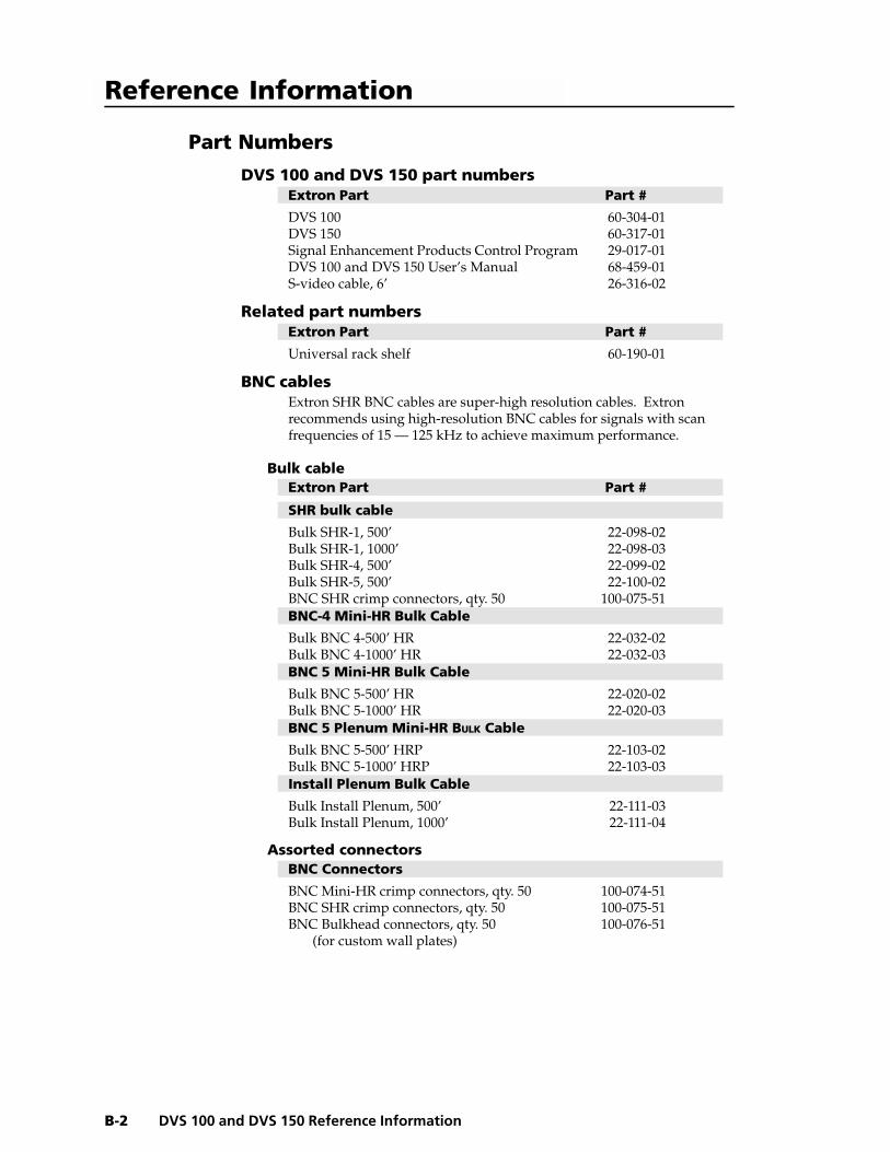
Part Numbers
DVS 100 and DVS 150 part numbersExtron Part Part #
DVS 100 60-304-01DVS 150 60-317-01Signal Enhancement Products Control Program 29-017-01DVS 100 and DVS 150 User’s Manual 68-459-01S-video cable, 6’ 26-316-02
Related part numbersExtron Part Part #
Universal rack shelf 60-190-01
BNC cablesExtron SHR BNC cables are super-high resolution cables. Extronrecommends using high-resolution BNC cables for signals with scanfrequencies of 15 — 125 kHz to achieve maximum performance.
Bulk cableExtron Part Part #
SHR bulk cable
Bulk SHR-1, 500’ 22-098-02Bulk SHR-1, 1000’ 22-098-03Bulk SHR-4, 500’ 22-099-02Bulk SHR-5, 500’ 22-100-02BNC SHR crimp connectors, qty. 50 100-075-51BNC-4 Mini-HR Bulk Cable
Bulk BNC 4-500’ HR 22-032-02Bulk BNC 4-1000’ HR 22-032-03BNC 5 Mini-HR Bulk Cable
Bulk BNC 5-500’ HR 22-020-02Bulk BNC 5-1000’ HR 22-020-03BNC 5 Plenum Mini-HR BULK Cable
Bulk BNC 5-500’ HRP 22-103-02Bulk BNC 5-1000’ HRP 22-103-03Install Plenum Bulk Cable
Bulk Install Plenum, 500’ 22-111-03Bulk Install Plenum, 1000’ 22-111-04
Assorted connectorsBNC Connectors
BNC Mini-HR crimp connectors, qty. 50 100-074-51BNC SHR crimp connectors, qty. 50 100-075-51BNC Bulkhead connectors, qty. 50 100-076-51 (for custom wall plates)
B-3DVS 100 and DVS 150 Reference Information
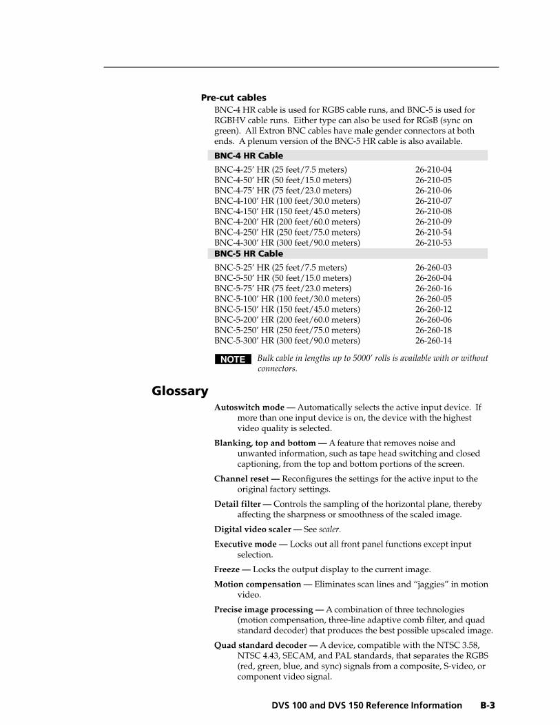
Pre-cut cablesBNC-4 HR cable is used for RGBS cable runs, and BNC-5 is used forRGBHV cable runs. Either type can also be used for RGsB (sync ongreen). All Extron BNC cables have male gender connectors at bothends. A plenum version of the BNC-5 HR cable is also available.
BNC-4 HR Cable
BNC-4-25’ HR (25 feet/7.5 meters) 26-210-04BNC-4-50’ HR (50 feet/15.0 meters) 26-210-05BNC-4-75’ HR (75 feet/23.0 meters) 26-210-06BNC-4-100’ HR (100 feet/30.0 meters) 26-210-07BNC-4-150’ HR (150 feet/45.0 meters) 26-210-08BNC-4-200’ HR (200 feet/60.0 meters) 26-210-09BNC-4-250’ HR (250 feet/75.0 meters) 26-210-54BNC-4-300’ HR (300 feet/90.0 meters) 26-210-53BNC-5 HR Cable
BNC-5-25’ HR (25 feet/7.5 meters) 26-260-03BNC-5-50’ HR (50 feet/15.0 meters) 26-260-04BNC-5-75’ HR (75 feet/23.0 meters) 26-260-16BNC-5-100’ HR (100 feet/30.0 meters) 26-260-05BNC-5-150’ HR (150 feet/45.0 meters) 26-260-12BNC-5-200’ HR (200 feet/60.0 meters) 26-260-06BNC-5-250’ HR (250 feet/75.0 meters) 26-260-18BNC-5-300’ HR (300 feet/90.0 meters) 26-260-14
Bulk cable in lengths up to 5000’ rolls is available with or withoutconnectors.
GlossaryAutoswitch mode — Automatically selects the active input device. If
more than one input device is on, the device with the highestvideo quality is selected.
Blanking, top and bottom — A feature that removes noise andunwanted information, such as tape head switching and closedcaptioning, from the top and bottom portions of the screen.
Channel reset — Reconfigures the settings for the active input to theoriginal factory settings.
Detail filter — Controls the sampling of the horizontal plane, therebyaffecting the sharpness or smoothness of the scaled image.
Digital video scaler — See scaler.
Executive mode — Locks out all front panel functions except inputselection.
Freeze — Locks the output display to the current image.
Motion compensation — Eliminates scan lines and “jaggies” in motionvideo.
Precise image processing — A combination of three technologies(motion compensation, three-line adaptive comb filter, and quadstandard decoder) that produces the best possible upscaled image.
Quad standard decoder — A device, compatible with the NTSC 3.58,NTSC 4.43, SECAM, and PAL standards, that separates the RGBS(red, green, blue, and sync) signals from a composite, S-video, orcomponent video signal.

Reference Information, cont’d
DVS 100 and DVS 150 Reference InformationB-4
Scaling — Changes the size of an image without changing its shape.Scaling can be used when the image size does not fit the displaydevice. A digital video scaler converts an NTSC, PAL, or SECAMimage to a size that can be displayed on a device with a fixedresolution and aspect ratio, such as an LCD (liquid crystal display)projectors, DLP (digital light processing) projectors, or plasmaprojector .
Sync polarity — A circuit can be designed to operate on the positive-going or negative-going part of the sync pulse. The DVS 100 andDVS 150 have menu options that allow you to select which edge(positive or negative) to trigger on.
System reset — Reconfigures all DVS 100 settings to the original factorysettings.
Three-line adaptive comb filter — A filter circuit that passes a series offrequencies and rejects the frequencies in between, producing afrequency response that resembles the teeth of a comb. Its preciseseparation of the chroma and luma signals reduces both crosschroma and cross luma artifacts (chroma crawl or “zipper”artifacts). It preserves more detail in the black-and-white,resulting in a better quality picture. Although comb filters aresuccessful in reducing artifacts, they may also cause a certainamount of loss of resolution in the picture. Each DVS 100 andDVS 150 uses a three-line adaptive comb filter, which examinesthree scan lines instead of one, producing a picture of higherquality than one produced by a standard comb filter.
FCC Class B NoticeThis equipment has been tested and found to comply with the limits for a Class B digital device,pursuant to part 15 of the FCC Rules. These limits are designed to provide reasonable protectionagainst harmful interference in a residential installation. This equipment generates, uses and canradiate radio frequency energy and, if not installed and used in accordance with the instructions,may cause harmful interference to radio communications. However, there is no guarantee that theinterference will not occur in a particular installation. If this equipment does cause harmfulinterference to radio or television reception, which can be determined by turning the equipment offand on, the user is encouraged to try to correct the interference by one or more of the followingmeasures:
• Reorient or relocate the receiving antenna.• Increase the separation between the equipment and receiver.• Connect the equipment into an outlet on a circuit different from that to which the receiver is
connected.• Consult the dealer or an experienced radio/TV technician for help.
This unit was tested with shielded cables on the peripheral devices. Shielded cables must be usedwith the unit to ensure compliance.
Extron’s WarrantyExtron Electronics warrants this product against defects in materials and workmanship for a periodof two years from the date of purchase. In the event of malfunction during the warranty periodattributable directly to faulty workmanship and/or materials, Extron Electronics will, at its option,repair or replace said products or components, to whatever extent it shall deem necessary to restoresaid product to proper operating condition, provided that it is returned within the warranty period,with proof of purchase and description of malfunction to:
USA, Canada, South Europe, Africa, and theAmerica, Central Middle East:America, and Asia:
Extron Electronics, EuropeExtron Electronics Beeldschermweg 6C1230 South Lewis Street 3821 AH AmersfoortAnaheim, CA 92805, U.S.A. The Netherlands
This Limited Warranty does not apply if the fault has been caused by misuse, improper handlingcare, electrical or mechanical abuse, abnormal operating conditions or non-Extron authorizedmodification to the product.
If it has been determined that the product is defective, please call Extron and ask for an ApplicationsEngineer at (714) 491-1500 (USA), 31.33.453.4040 (Europe), or 65.226.0015 (Asia) to receive an RA# (ReturnAuthorization number). This will begin the repair process as quickly as possible.
Units must be returned insured, with shipping charges prepaid. If not insured, you assume the riskof loss or damage during shipment. Returned units must include the serial number and adescription of the problem, as well as the name of the person to contact in case there are anyquestions.
Extron Electronics makes no further warranties either expressed or implied with respect to theproduct and its quality, performance, merchantability, or fitness for any particular use. In no eventwill Extron Electronics be liable for direct, indirect, or consequential damages resulting from anydefect in this product even if Extron Electronics has been advised of such damage.
Please note that laws vary from state to state and country to country, and that some provisions ofthis warranty may not apply to you.

EXTRON ELECTRONICS/RGB SYSTEMS, INC.1230 South Lewis Street, Anaheim, CA 92805800.633.9876 714.491.1500 FAX 714.491.1517U.S.A.
EXTRON ELECTRONICS, EUROPEBeeldschermweg 6C, 3821 AH Amersfoort+31.33.453.4040 FAX +31.33.453.4050The Netherlands
EXTRON ELECTRONICS, ASIA41B Kreta Ayer Road, Singapore 089003+65.226.0015 FAX +65.226.0019Singapore
EXTRON ELECTRONIC INFORMATIONEXTRONWEB™: www.extron.comEXTRONFAX™: 714.491.019224-hour access—worldwide!