dx-9200 lonworks compatible digital controller technical
TRANSCRIPT
LONWORKS Systems Manual 1162 DX-9200 Section Technical Bulletin Issue Date May 6, 2004
© 2004 Johnson Controls, Inc. 1 Code No. LIT-1162250 www.johnsoncontrols.com
DX-9200 LONWORKS® Compatible Digital Controller
DX-9200 LONWORKS Compatible Digital Controller 5
About This Manual 5 Introduction 5 Features 6 Installation 8 General Wiring Guidelines 20 Battery Replacement 21 Startup 23
LONWORKS Neuron® ID 24
Inputs/Outputs 25
Analog Inputs 25 Digital Inputs 26 Digital Counters 26 Analog Outputs 26 Digital Outputs 27 Analog/Digital Constants and Logic Result Status 28 Extension Modules 29 Network Inputs/Outputs 31
2 DX-9200—DX-9200 LONWORKS Compatible Digital Controller
Operation 35
Introduction 35 Realtime Functions 36 Time Schedule Modules 37 Optimal Start/Stop Modules 38 Optimal Start Adaptive Process 39 Optimal Stop Operation 41 Programmable Function Modules: Control Algorithms 42 Numeric Calculation Algorithms 58 Other Functions 62 Programmable Logic Control 68 Password Feature 75 Trend Log Feature for Local DX LCD Display 75
Software Configuration 77
General 77 DX-9200 Global Data 77 Network Analog Input Configuration 77 Network Digital Input Configuration 78 Network Analog Output Configuration 80 Network Digital Output Configuration 81 Trend Log Configuration 82 Supervisory Mode Control Settings (General Module) 83 Controller Diagnostics 86 Power Up Conditions 87 Download/ Upload 88 Calibration Values 89 Network Configuration and Node Control Network Variables 90
Display Panel and Keypads 93
Front Panel Layout 93 Startup 96 Download 96 Time Schedule Mode 97
DX-9200—DX-9200 LonWorks Compatible Digital Controller 3
Time Schedule Event Programming 98 Realtime Clock Calendar 99 Analog Input Display Mode 103 Analog Input Scroll Mode 104 Digital Input Display Mode 104 Output Module Display Mode 104 Digital Counter Display Mode 106 Programmable Function Module Display Mode 107 Analog/Digital Constant Display Mode 110
Specifications and Technical Data 111
Ordering Codes 113
LONMARK Network Variables 115
DX-9200-8454-A and DX-9200-8454-AA General Purpose Room Control Applications 115 DX-9200-8454-D and DX-9200-8454-DA AHU or Discharge Air Control Applications 117 Configuration and Node Control Network Variables Valid for All DX-9200-8454 Models 119
Network Variable Internal Mapping Tables 121
DX-9200-8454-A (LONDXA) and DX-9200-8454-AA (LONDXAA) 121 DX-9200-8454-D (LONDXD) and DX-9200-8454-DA (LONDXDA) 124

4 DX-9200—DX-9200 LONWORKS Compatible Digital Controller
DX-9200—DX-9200 LonWorks Compatible Digital Controller 5
DX-9200 LONWORKS Compatible Digital Controller
This document provides technical details and configuration information for the DX-9200 series of LONWORKS® compatible digital plant controllers. This includes information on mounting, installation, and startup.
About This Manual
The only difference between the software configuration of DX-9200 series of controllers and the DX-9121 controller is the LONWORKS network interface. This document includes only the additional information required to configure a DX-9200 controller and does not repeat the information in the DX-9100 Configuration Guide (LIT-6364030). Refer to the DX-9100 Configuration Guide (LIT-6364030) when configuring the DX-9200 series of controllers. Refer to the Display Panel and Keypad chapter later in this document for instructions for operating the front panel and keypad.
Related Documentation Table 1: Related Documentation
Document Title Code Number FAN DX-9100 Configuration Guide LIT-6364030 636.4 GX-9100 Software Configuration Tool User’s Guide LIT-6364060 636.4 LONWORKS Network Layout Technical Bulletin LIT-1162150 1162 LONWORKS Compatible Devices Supported by NCM350 Technical Bulletin
LIT-1162100 1162
SX-9120 Service Module User’s Guide LIT-6364070 636.4 XTM-905 Technical Bulletin LIT-6364210 636.4 XT-9100 Technical Bulletin LIT-6364040 636.4
The DX-9200 is a LONWORKS compatible controller for installation in a LONWORKS network with other LONWORKS compatible devices. The controller is the ideal solution for the control of HVAC (Heating, Ventilating, and Air Conditioning) equipment, including Air Handling Units (AHUs). It is also suitable for the control of zone temperature, terminal units, lighting, and related electrical equipment. The controller provides precise direct digital control as well as programmed logic control.
Introduction
6 DX-9200—DX-9200 LONWORKS Compatible Digital Controller
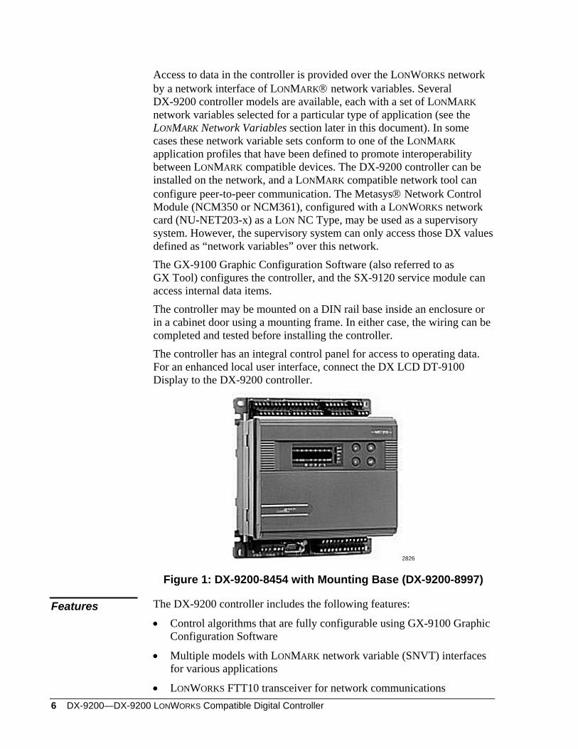
Access to data in the controller is provided over the LONWORKS network by a network interface of LONMARK® network variables. Several DX-9200 controller models are available, each with a set of LONMARK network variables selected for a particular type of application (see the LONMARK Network Variables section later in this document). In some cases these network variable sets conform to one of the LONMARK application profiles that have been defined to promote interoperability between LONMARK compatible devices. The DX-9200 controller can be installed on the network, and a LONMARK compatible network tool can configure peer-to-peer communication. The Metasys® Network Control Module (NCM350 or NCM361), configured with a LONWORKS network card (NU-NET203-x) as a LON NC Type, may be used as a supervisory system. However, the supervisory system can only access those DX values defined as “network variables” over this network. The GX-9100 Graphic Configuration Software (also referred to as GX Tool) configures the controller, and the SX-9120 service module can access internal data items. The controller may be mounted on a DIN rail base inside an enclosure or in a cabinet door using a mounting frame. In either case, the wiring can be completed and tested before installing the controller. The controller has an integral control panel for access to operating data. For an enhanced local user interface, connect the DX LCD DT-9100 Display to the DX-9200 controller.
2826
Figure 1: DX-9200-8454 with Mounting Base (DX-9200-8997)
The DX-9200 controller includes the following features: Features • Control algorithms that are fully configurable using GX-9100 Graphic
Configuration Software
• Multiple models with LONMARK network variable (SNVT) interfaces for various applications
• LONWORKS FTT10 transceiver for network communications
DX-9200—DX-9200 LonWorks Compatible Digital Controller 7
• RS-232-C port for loading controller configurations and for connection of DX LCD Display
• Socket for service module (SX-9120) connection
• Eight high resolution (13-bit) analog inputs
• Eight digital (binary) inputs from potential-free contacts
• Eight isolated analog outputs
• Six isolated digital (binary) outputs (triacs)
• Twelve programmable function modules, selected from a library of functions, including:
- P, PI, PID, or on/off control, dual PID, dual on/off control - Numeric calculation modules for programmed mathematical
function - Sequencer modules - Totalization modules for analog or digital inputs
• Programmable logic control module with a set of logic functions including AND, ANDNOT, OR, ORNOT, COS (Change-of-State), OUT, OUTNOT, SET, RESET, AND LOGIC BLOCK, and OR LOGIC BLOCK
• Eight time schedule modules
• Two optimal start/stop modules
• Trend log support for the DX LCD Display
• Eight extension Input/Output modules, each supporting up to eight I/O
• Sensor readings updated every second (including inputs from up to four extension modules with analog inputs/outputs).
• Up to 62 LONMARK network variables for network inputs/outputs (depending on the model)
• Integral display with keyboard
• Enclosure material of self-extinguishing ABS/polycarbonate
• Mountable on DIN rail or cabinet door for field wiring
• Built-in isolation transformer
• CE Mark and CSA Certified (Underwriters Laboratories Inc.® [UL] Listing Pending)
8 DX-9200—DX-9200 LONWORKS Compatible Digital Controller
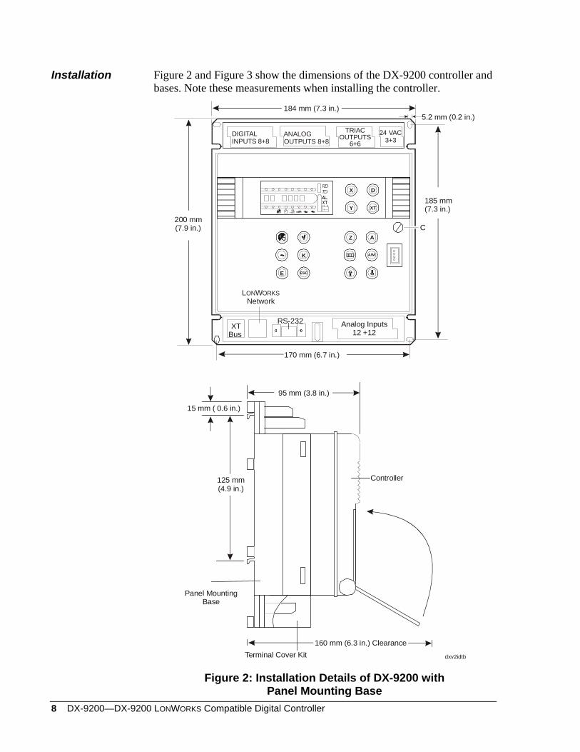
Installation Figure 2 and Figure 3 show the dimensions of the DX-9200 controller and bases. Note these measurements when installing the controller.
170 mm (6.7 in.)
DIGITALINPUTS 8+8
TRIAC
OUTPUTS
6+624 VAC
3+3
XT Bus
Analog Inputs12 +12
200 mm(7.9 in.)
185 mm(7.3 in.)
RS-232
5.2 mm (0.2 in.)
dxv2idtb
125 mm(4.9 in.)
Terminal Cover Kit
Panel MountingBase
95 mm (3.8 in.)
15 mm ( 0.6 in.)
Controller
160 mm (6.3 in.) Clearance
XT
X
Y
D
ESCE
K
Z A
A/M
RDTD
L WNetworkON ORKS
184 mm (7.3 in.)
C
ANALOGOUTPUTS 8+8
Figure 2: Installation Details of DX-9200 with Panel Mounting Base
DX-9200—DX-9200 LonWorks Compatible Digital Controller 9
Ddxv3fptb
Omega Rail35 mm (1.375 in.)
DIN/EN 50022
TerminalCover
TerminalCover
35 mm(1.375 in.)
125 mm(4.9 in.)
DIGITALINPUTS 8+8
TRIAC
OUTPUTS
6+624 VAC
3+3
XT Bus
Analog Inputs12 +12
RS-232
XT
X
Y
D
ESCE
K
Z A
A/M
RDTD
L WNetworkON ORKS
C
ANALOG
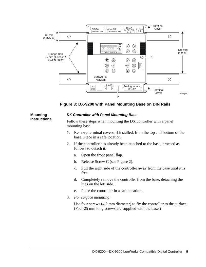
Figure 3: DX-9200 with Panel Mounting Base on DIN Rails
Mounting Instructions
DX Controller with Panel Mounting Base
Follow these steps when mounting the DX controller with a panel mounting base: 1. Remove terminal covers, if installed, from the top and bottom of the
base. Place in a safe location. 2. If the controller has already been attached to the base, proceed as
follows to detach it: a. Open the front panel flap. b. Release Screw C (see Figure 2). c. Pull the right side of the controller away from the base until it is
free. d. Completely remove the controller from the base, detaching the
lugs on the left side. e. Place the controller in a safe location.
3. For surface mounting: Use four screws (4.2 mm diameter) to fix the controller to the surface.
(Four 25 mm long screws are supplied with the base.)
10 DX-9200—DX-9200 LONWORKS Compatible Digital Controller
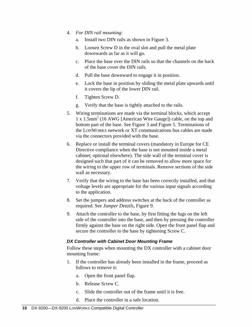
4. For DIN rail mounting: a. Install two DIN rails as shown in Figure 3. b. Loosen Screw D in the oval slot and pull the metal plate
downwards as far as it will go. c. Place the base over the DIN rails so that the channels on the back
of the base cover the DIN rails. d. Pull the base downward to engage it in position. e. Lock the base in position by sliding the metal plate upwards until
it covers the lip of the lower DIN rail. f. Tighten Screw D. g. Verify that the base is tightly attached to the rails.
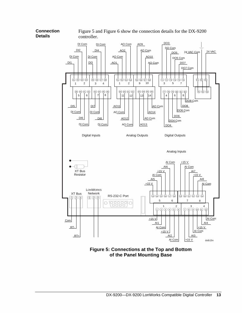
5. Wiring terminations are made via the terminal blocks, which accept 1 x 1.5mm2 (16 AWG [American Wire Gauge]) cable, on the top and bottom part of the base. See Figure 3 and Figure 5. Terminations of the LONWORKS network or XT communications bus cables are made via the connectors provided with the base.
6. Replace or install the terminal covers (mandatory in Europe for CE Directive compliance when the base is not mounted inside a metal cabinet; optional elsewhere). The side wall of the terminal cover is designed such that part of it can be removed to allow more space for the wiring to the upper row of terminals. Remove sections of the side wall as necessary.
7. Verify that the wiring to the base has been correctly installed, and that voltage levels are appropriate for the various input signals according to the application.
8. Set the jumpers and address switches at the back of the controller as required. See Jumper Details, Figure 9.
9. Attach the controller to the base, by first fitting the lugs on the left side of the controller into the base, and then by pressing the controller firmly against the base on the right side. Open the front panel flap and secure the controller to the base by tightening Screw C.
DX Controller with Cabinet Door Mounting Frame Follow these steps when mounting the DX controller with a cabinet door mounting frame: 1. If the controller has already been installed in the frame, proceed as
follows to remove it: a. Open the front panel flap. b. Release Screw C. c. Slide the controller out of the frame until it is free. d. Place the controller in a safe location.
DX-9200—DX-9200 LonWorks Compatible Digital Controller 11
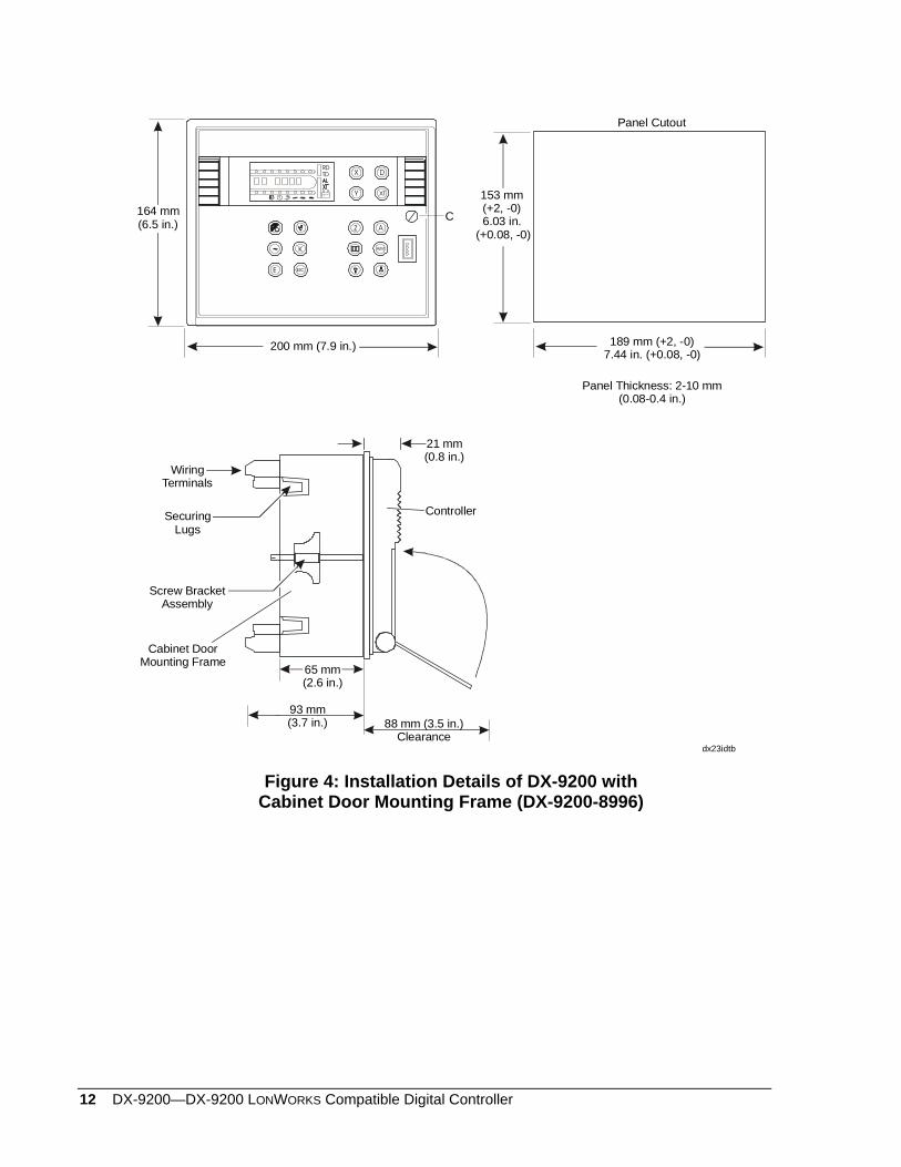
2. Make a cutout in the cabinet door as shown in Figure 4. Note that the frame may be mounted in a panel with a thickness of 2-10 mm.
Slide the frame into the cutout and secure using the two screw bracket assemblies provided.
3. Make wiring terminations via the terminal blocks, which accept 1 x 1.5 mm (16 AWG) at the back of the frame. See Figure 4 and Figure 6. Make terminations of the LONWORKS network and XT communications bus cables via the connectors provided with the base.
4. Verify that the wiring to the frame has been correctly installed, and that voltage levels are appropriate for the various input signals according to the application.
5. Set the jumpers and address switches at the back of the controller as required. See Jumper Details, Figure 9.
6. Slide the controller into the frame until the lugs on the left hand side of the frame engage the controller. Open the front panel flap and secure the controller to the frame by tightening Screw C.
12 DX-9200—DX-9200 LONWORKS Compatible Digital Controller
dx23idtb
XT
X
Y
D
ESCE
K
Z A
A/M
RDTD
164 mm(6.5 in.)
C
200 mm (7.9 in.)
Panel Cutout
189 mm (+2, -0)7.44 in. (+0.08, -0)
Panel Thickness: 2-10 mm(0.08-0.4 in.)
153 mm(+2, -0)6.03 in.
(+0.08, -0)
Wiring Terminals
SecuringLugs
Screw BracketAssembly
21 mm(0.8 in.)
65 mm(2.6 in.)
93 mm(3.7 in.) 88 mm (3.5 in.)
Clearance
Controller
Cabinet DoorMounting Frame
Figure 4: Installation Details of DX-9200 with Cabinet Door Mounting Frame (DX-9200-8996)
DX-9200—DX-9200 LonWorks Compatible Digital Controller 13
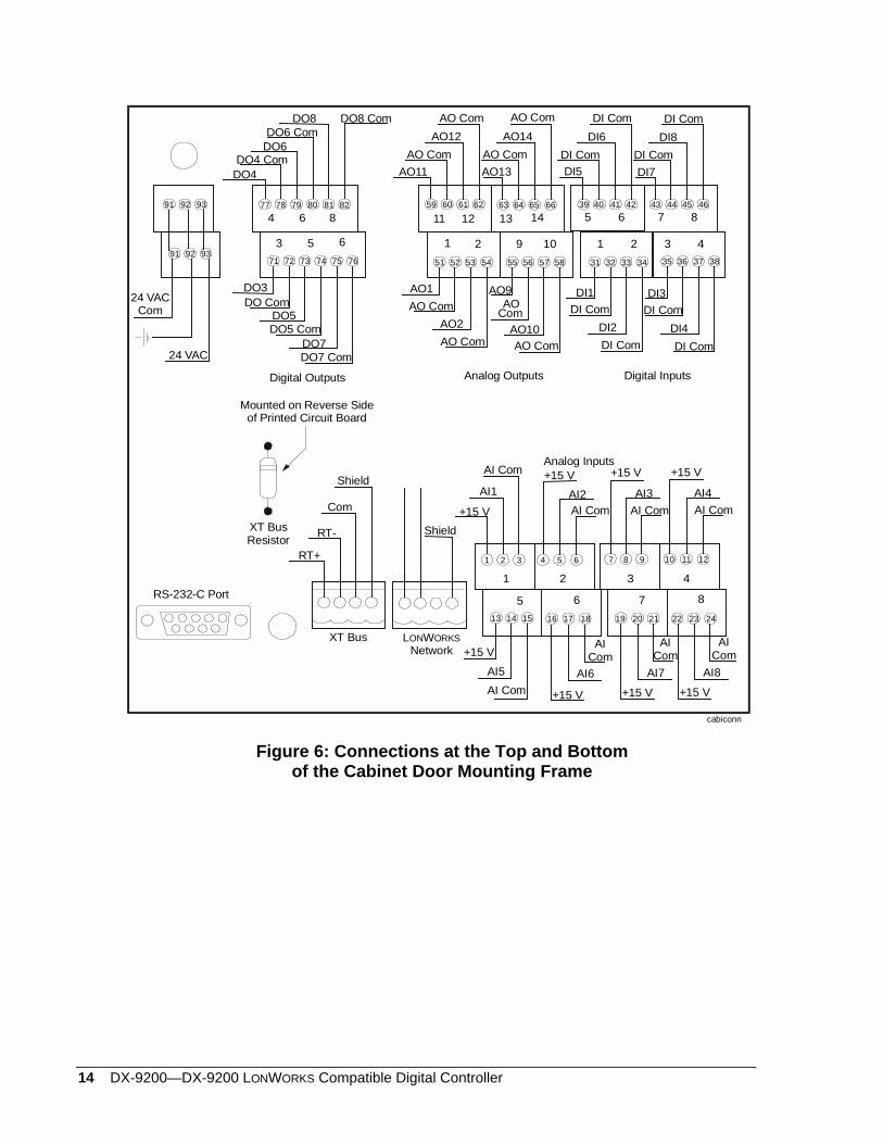
Connection Details
Figure 5 and Figure 6 show the connection details for the DX-9200 controller.
dxtb15n
1 9
11 13
3
4
Digital Inputs
DI1
DI Com
DI2
DI Com
DI3
DI Com
DI4
DI Com
AO1
AO Com
AO2
AO Com AO9
AO Com
AO10
AO Com
DI5
DI Com
DI6
DI Com
DI7
DI Com
DI8
DI Com
DO3
DO ComDO5
DO5 Com
DO7
DO7 Com
DO4 ComDO6
DO6 ComDO8
DO8 Com
DO4
24 VAC Com 24 VAC
AO11
AO Com
AO12
AO Com AO13
AO Com
AO14
AO Com
1 3
5 7
3231 33 34 35 36 37 38 51 52 53 54 55 56 57 58 71 72 73 74 75 76 91 92 93
+15 VAI5
AI Com+15 V
AI6AI Com
5 6
1 2
+15 VAI1AI Com
+15 V
AI ComAI2
+15 VAI7
AI Com+15 V
AI8AI Com
7 8
3 4
+15 VAI3
AI Com+15 V
AI ComAI4
Com
RT-
RT+
XT BusRS-232-C Port 13 14 15 16 17 18 19 20 21 22 23 24
21 3 1 32
39 40 41 42 43 44 45 46 59 60 61 62 63 64 65 66 77 78 79 80 81 82 91 92 93
1 2 3 4 5 6 7 8 9 10 11 12
Analog Outputs Digital Outputs
Analog Inputs
XT BusResistor
L WNetworkON ORKS
6 8 12 14
2 4 2 10 5 7
6 8
Figure 5: Connections at the Top and Bottom of the Panel Mounting Base
14 DX-9200—DX-9200 LONWORKS Compatible Digital Controller
51
59
58
6677
76
8291 92 93
91 92 93
Digital Inputs
DI1DI Com
DI2DI ComDI3
DI ComDI4
DI Com
AO1
AO ComAO2
AO ComAO9
ComAO10AO Com
DI5DI Com
DI6DI Com
DI7DI Com
DI8DI Com
DO3DO Com
DO5DO5 Com
DO7DO7 Com
DO4 ComDO6DO6 Com
DO8 DO8 Com
DO4
24 VAC Com
24 VAC
AO11AO Com
AO12AO Com
AO13
AO ComAO14
AO Com
60 61 62 63 64 6578 79 80 815 7
46
38
40 41 42 43 44 45
32 33 34 36 3752 53 54 55 56 5772 73 74 75
+15 V
AI5
AI Com+15 V
AI6AI Com
5 6
1 2
+15 V
AI1
AI Com +15 V
AI ComAI2
+15 V
AI7
AI Com
+15 V
AI8
AI Com
7 8
3 4
+15 V
AI3AI Com
+15 V
AI ComAI4
RS-232-C Port
86
3 431 35
1 2
39
11 12 13 14
1 2 9 1071
Digital Outputs Analog Outputs
Analog Inputs
Com
RT-
RT+
Shield
Shield
XT Bus L WNetworkON ORKS
4
3
6
5
8
6
XT BusResistor
Mounted on Reverse Side of Printed Circuit Board
8 9 10 11 1274 5 62 31
cabiconn
19 20 2114 15 16 17 18 2422 2313
AO
Figure 6: Connections at the Top and Bottom of the Cabinet Door Mounting Frame
DX-9200—DX-9200 LonWorks Compatible Digital Controller 15
The connection, wiring, and jumper information that follows is valid for DX-9200 controllers with either type of mounting (panel mounting base or cabinet door mounting frame). Notes: The following commons are electrically independent:
Analog Input Common (for AI1 to AI8) Analog Output Common (for AO1, AO2, AO9 to AO14) 24 VAC Common/Digital Input Common (for DI1 to DI8)
(24 VAC Common and Digital Input Common are electrically connected.)
Digital Output 3 Common Digital Output 4 Common Digital Output 5 Common Digital Output 6 Common Digital Output 7 Common Digital Output 8 Common XT Bus Common (Reference)
If required by local electrical codes, the 24 VAC Common/Digital Input Common may be connected to a clean earth/ground termination. The Analog Output Common may be connected to the 24 VAC Common at the controller for actuator devices with a single common terminal for 24 VAC Common and Analog Signal Common. Under no circumstances should the 24 VAC or any of the Analog Outputs (AO1…AO14) be connected to an earth/ground termination.
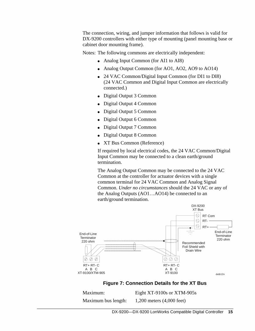
dxtb12n
RT-
RT+
DX-9200XT Bus
RT Com
RT+ RT- CA B CXT-9100
End-of-LineTerminator220 ohm
RT+ RT- CA B C
XT-9100/XTM-905
RecommendedFoil Shield with
Drain Wire
End-of-LineTerminator220 ohm
Figure 7: Connection Details for the XT Bus
Maximum: Eight XT-9100s or XTM-905s Maximum bus length: 1,200 meters (4,000 feet)
16 DX-9200—DX-9200 LONWORKS Compatible Digital Controller
Install 220-ohm end-of-line resistors at each end of the XT Bus line when the bus length is greater than 100 meters (330 feet). When the DX-9200 is at one end of the bus, the end-of-line resistor is already installed in the mounting base or frame. When the DX-9200 is not at one end of the bus, install two resistors externally, and use side-cutters to remove the “XT BUS RESISTOR” on the mounting base or frame. (See Figure 5 and Figure 6.) When the bus length is less than 100 meters (330 feet), no external resistors are required, but the end-of-line resistor in the mounting frame must not be removed.
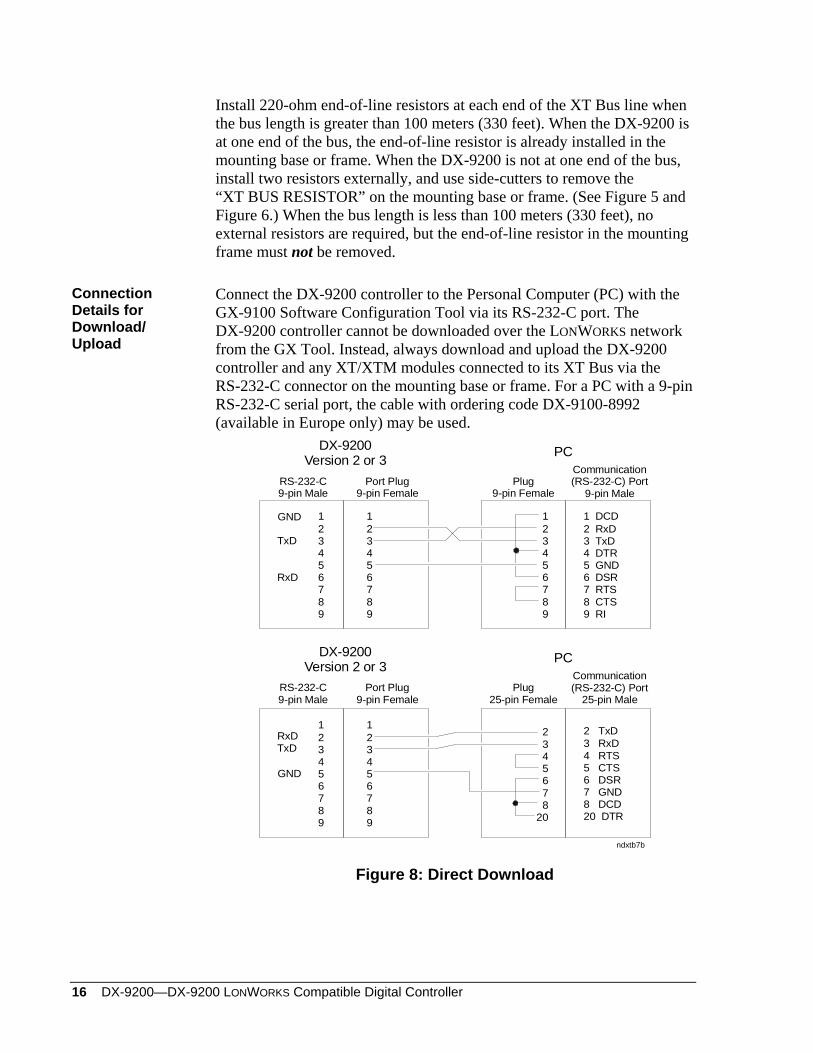
Connection Details for Download/ Upload
Connect the DX-9200 controller to the Personal Computer (PC) with the GX-9100 Software Configuration Tool via its RS-232-C port. The DX-9200 controller cannot be downloaded over the LONWORKS network from the GX Tool. Instead, always download and upload the DX-9200 controller and any XT/XTM modules connected to its XT Bus via the RS-232-C connector on the mounting base or frame. For a PC with a 9-pin RS-232-C serial port, the cable with ordering code DX-9100-8992 (available in Europe only) may be used.
DX-9200Version 2 or 3
RS-232-C 9-pin Male
Port Plug9-pin Female
Communication(RS-232-C) Port
9-pin MalePlug
9-pin Female
123456789
1 DCD2 RxD3 TxD4 DTR5 GND6 DSR7 RTS8 CTS9 RI
PC
123456789
123456789
ndxtb7b
RxD
TxD
GND
2345678
20
2 TxD3 RxD4 RTS5 CTS6 DSR7 GND8 DCD20 DTR
123456789
123456789
RxDTxD
GND
DX-9200Version 2 or 3
RS-232-C 9-pin Male
Port Plug9-pin Female
Communication(RS-232-C) Port
25-pin MalePlug
25-pin Female
PC
Figure 8: Direct Download
DX-9200—DX-9200 LonWorks Compatible Digital Controller 17
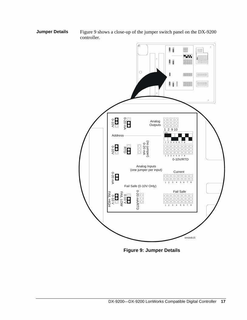
Jumper Details Figure 9 shows a close-up of the jumper switch panel on the DX-9200 controller.
1 2 9 10
Fail Safe (0-10V Only)
AnalogOutputs
0-20 mA
0-10VAddress
RTD
0-10V
FAIL LO
W
0-10V
FAIL HIG
H
0-20 mA
/RTD
0-20 mA
Current
0-10V/RTD
Fail Safe
Analog Inputs(one jumper per input)
1 2 3 4 5 6 7 8
ON
1 2 3 4 5 6 7 8
0-10V
1 2 3 4 5 86 7
1 2 3 4 5 86 7
emdxtb15
(no jumper)
0-20 mA
Figure 9: Jumper Details
18 DX-9200—DX-9200 LONWORKS Compatible Digital Controller
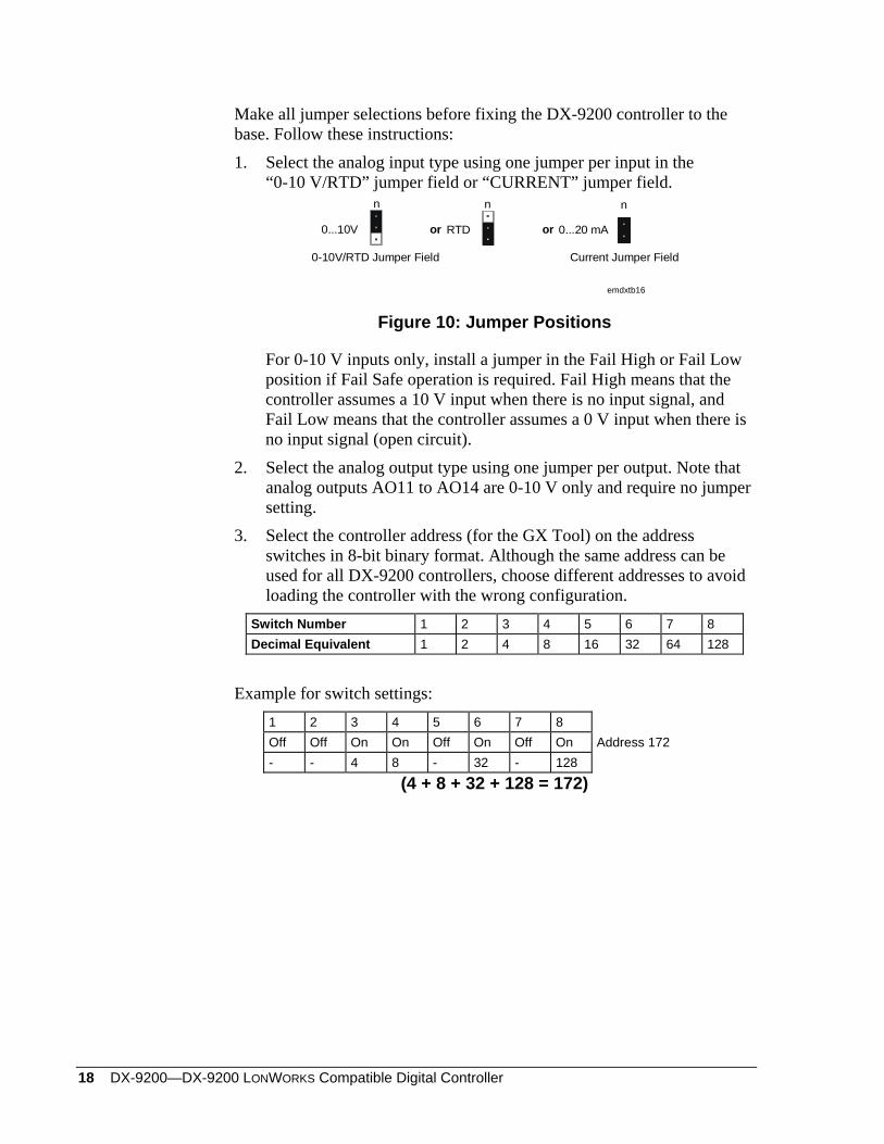
Make all jumper selections before fixing the DX-9200 controller to the base. Follow these instructions: 1. Select the analog input type using one jumper per input in the
“0-10 V/RTD” jumper field or “CURRENT” jumper field.
emdxtb16
n
or 0...20 mA
n
0-10V/RTD Jumper Field
0...10V
n
or RTD
Current Jumper Field
Figure 10: Jumper Positions
For 0-10 V inputs only, install a jumper in the Fail High or Fail Low position if Fail Safe operation is required. Fail High means that the controller assumes a 10 V input when there is no input signal, and Fail Low means that the controller assumes a 0 V input when there is no input signal (open circuit).
2. Select the analog output type using one jumper per output. Note that analog outputs AO11 to AO14 are 0-10 V only and require no jumper setting.
3. Select the controller address (for the GX Tool) on the address switches in 8-bit binary format. Although the same address can be used for all DX-9200 controllers, choose different addresses to avoid loading the controller with the wrong configuration.
Switch Number 1 2 3 4 5 6 7 8 Decimal Equivalent 1 2 4 8 16 32 64 128
Example for switch settings:
1 2 3 4 5 6 7 8 Off Off On On Off On Off On Address 172 - - 4 8 - 32 - 128
(4 + 8 + 32 + 128 = 172)
DX-9200—DX-9200 LonWorks Compatible Digital Controller 19
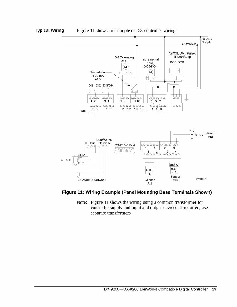
Typical Wiring Figure 11 shows an example of DX controller wiring.
L WNetworkON ORKS
XT Bus
DI5
XT BusCOMRT-RT+
SensorAI4
S15V
SensorAI1
RTD
150-10V Sensor
AI8
DI1 DI2 DI3/DI4
0-10V AnalogAO1 Incremental
(PAT)DO3/DO4
On/Off, DAT, Pulse,or Start/Stop
DO5 DO6
Transducer4-20 mA
AO9
24 VACSupplyCOMMON
MM
emdxtb17
RS-232-C Port
1 2 9 10
11 12 13 14
3 5 7
4 6 8
1 2 3 4
5 6 7 8
31 32 33 34 35 36 37 38
39 40 41 42 43 44 45 46
51 52 53 54 55 56 57 58
66656463626159 60
71 72 73 74 75 76
77 78 79 80 81 82 91 92 93
939291
5 61 2
7 83 4
13 14 15 16 17 18 19 20 21 22 23 24
121110987654321
0-20mA
321321
L W NetworkON ORKS
Figure 11: Wiring Example (Panel Mounting Base Terminals Shown)
Note: Figure 11 shows the wiring using a common transformer for controller supply and input and output devices. If required, use separate transformers.
20 DX-9200—DX-9200 LONWORKS Compatible Digital Controller
General Wiring Guidelines
Every reasonable precaution has been taken to prevent electrical disturbances from adversely affecting the operation of the controller. The controller complies with appropriate local codes for Electromagnetic Compatibility (EMC). However, a lack of attention to generally accepted control wiring installation practices can lead to controller problems in high electromagnetic field environments. In general, follow the guidelines below.
Do not mount the controller in heavy-duty switchgear cabinets or in cabinets with frequency-converting or phase-cutting equipment.
Separate low voltage wiring in electrical cabinets from line voltage and power wiring, and use a distinctive color of wire (e.g., white or pink) for different types of wiring.
To avoid electrical interference in field cables: - Keep input and output point cable runs as short as possible
(< 50 m [165 feet]). - Use twisted pair cables. - Run low voltage cables separately from line voltage/power cables,
and use a minimum of 30 cm (12 inches) separation for 230V 30A circuits.
- Do not run low voltage cables parallel to power cables for long distances (> 3 m [10 feet]).
- Do not run cables close to transformers or high frequency generating equipment.
- In high electromagnetic field environments, use shielded cable, grounding the drain wire at the controller cabinet only.
- Use a cable recommended for RS-485 transmission for the XT Bus (extension module bus). If the cable is shielded, it must be grounded at one point only (normally at one end of the bus). If a two-wire cable is installed, the shield may be used for the RS-485 common (or reference) signal.
- For the LONWORKS communications network, use a balanced 110-ohm twisted pair cable. If the cable is shielded, then always ground it at only one point (normally at one end of the bus). Refer to the LONWORKS Network Layout Technical Bulletin (LIT-1162150).
Do not connect switched inductive loads to the 24 V transformer that supplies the controller. When multiple loads are connected to one transformer, cable each connected load from the transformer separately so that any possible disturbances from one load will have minimal affect on other loads.
DX-9200—DX-9200 LonWorks Compatible Digital Controller 21
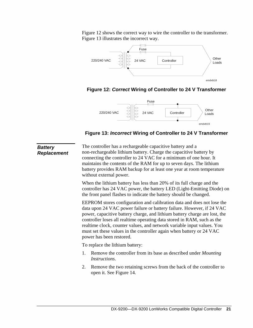
Figure 12 shows the correct way to wire the controller to the transformer. Figure 13 illustrates the incorrect way.
OtherLoads
Fuse
24 VAC220/240 VAC Controller
emdxtb18
Figure 12: Correct Wiring of Controller to 24 V Transformer
Fuse
24 VAC220/240 VAC Controller
emdxtb19
OtherLoads
Figure 13: Incorrect Wiring of Controller to 24 V Transformer
The controller has a rechargeable capacitive battery and a non-rechargeable lithium battery. Charge the capacitive battery by connecting the controller to 24 VAC for a minimum of one hour. It maintains the contents of the RAM for up to seven days. The lithium battery provides RAM backup for at least one year at room temperature without external power.
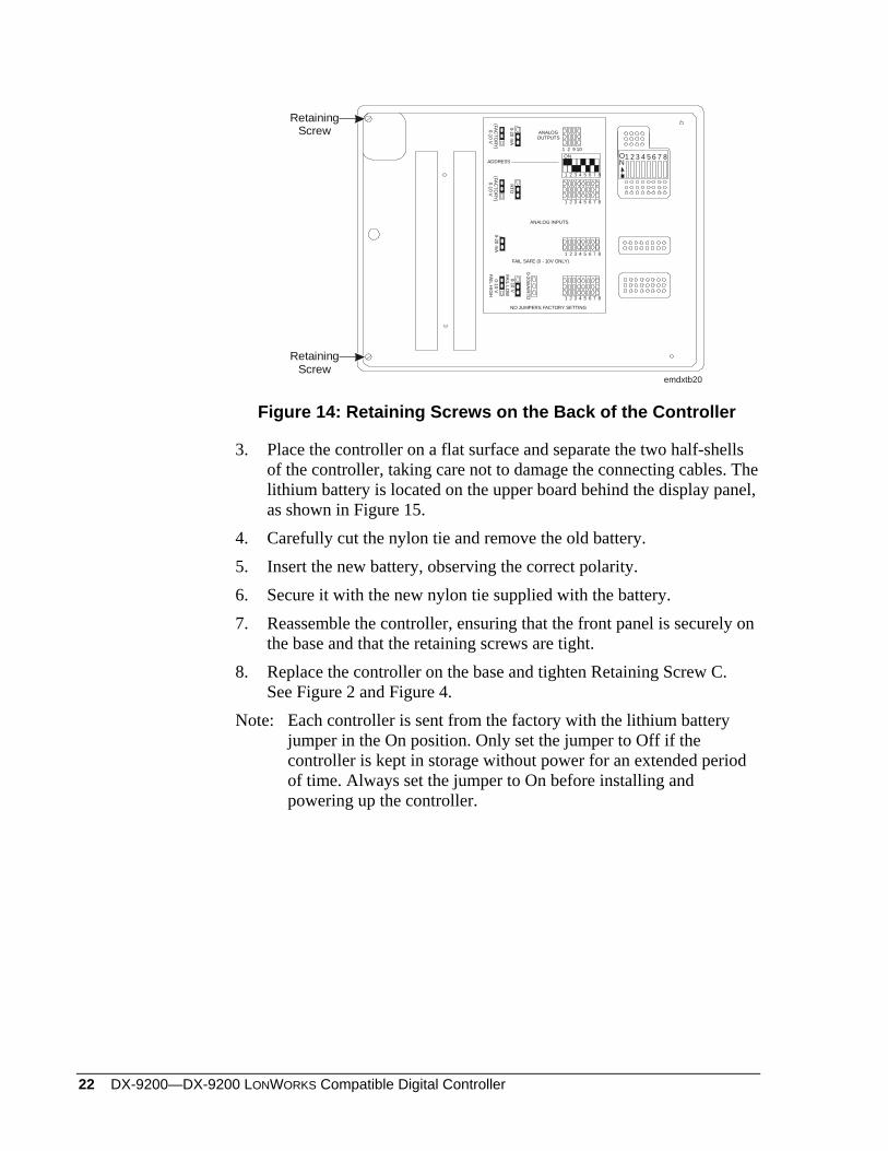
Battery Replacement
When the lithium battery has less than 20% of its full charge and the controller has 24 VAC power, the battery LED (Light-Emitting Diode) on the front panel flashes to indicate the battery should be changed. EEPROM stores configuration and calibration data and does not lose the data upon 24 VAC power failure or battery failure. However, if 24 VAC power, capacitive battery charge, and lithium battery charge are lost, the controller loses all realtime operating data stored in RAM, such as the realtime clock, counter values, and network variable input values. You must set these values in the controller again when battery or 24 VAC power has been restored. To replace the lithium battery: 1. Remove the controller from its base as described under Mounting
Instructions. 2. Remove the two retaining screws from the back of the controller to
open it. See Figure 14.
22 DX-9200—DX-9200 LONWORKS Compatible Digital Controller
emdxtb20
RetainingScrew
RetainingScrew
1 2 3 4 5 6 7 8ON
1 2 9 10
1 2 3 4 5 6 7 8
1 2 3 4 5 6 7 8
1 2 3 4 5 6 7 8
1 2 3 4 5 6 7 8
NO JUMPERS FACTORY SETTING
FAIL SAFE (0 - 10V ONLY)
ANALOG INPUTS
ANALOGOUTPUTS
0-20 mA
(FACTO
RY) 0-10 V
ADDRESS
RTD
(FACTO
RY)0-10
V
0-10 VFAIL LO
W
0-10 VFAIL H
IGH
0-20mA/R
TD
0-20 mA
ON
Figure 14: Retaining Screws on the Back of the Controller
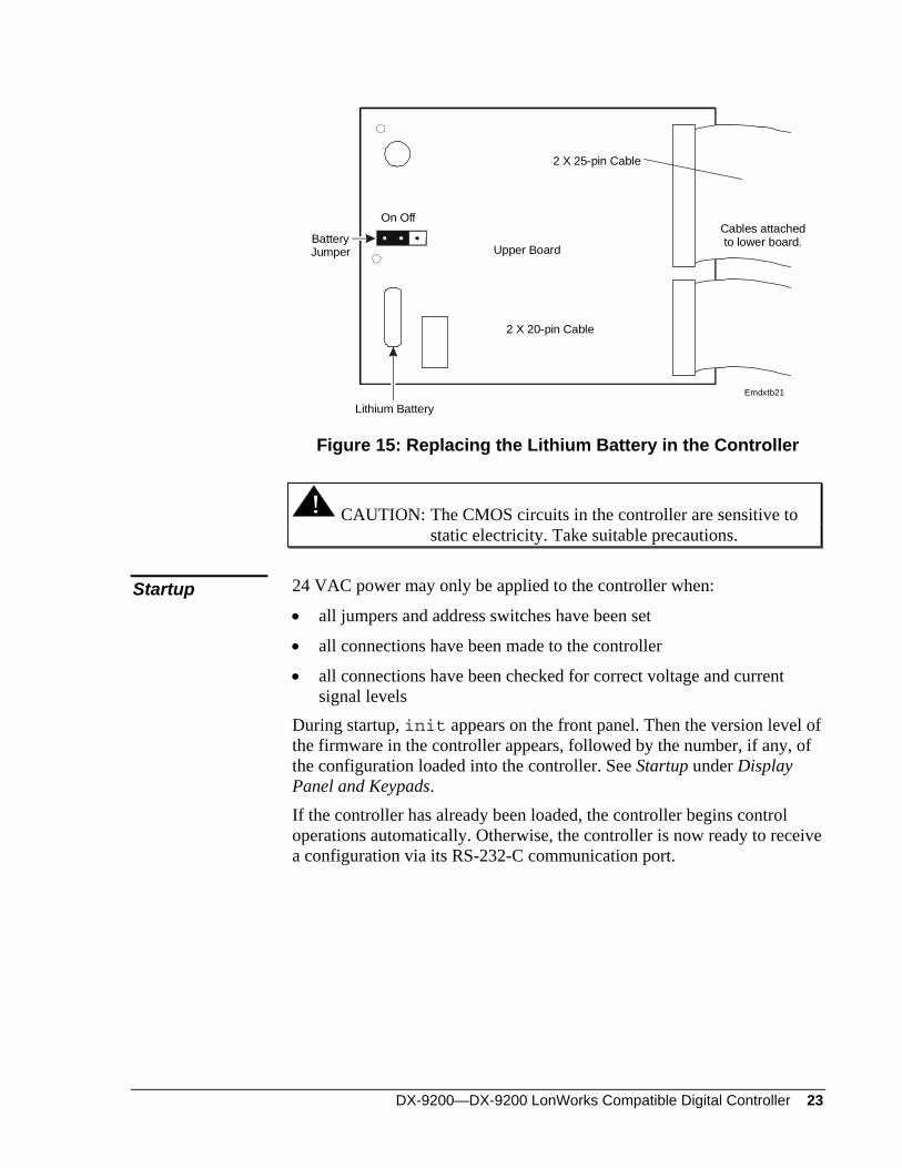
3. Place the controller on a flat surface and separate the two half-shells of the controller, taking care not to damage the connecting cables. The lithium battery is located on the upper board behind the display panel, as shown in Figure 15.
4. Carefully cut the nylon tie and remove the old battery. 5. Insert the new battery, observing the correct polarity. 6. Secure it with the new nylon tie supplied with the battery. 7. Reassemble the controller, ensuring that the front panel is securely on
the base and that the retaining screws are tight. 8. Replace the controller on the base and tighten Retaining Screw C.
See Figure 2 and Figure 4. Note: Each controller is sent from the factory with the lithium battery
jumper in the On position. Only set the jumper to Off if the controller is kept in storage without power for an extended period of time. Always set the jumper to On before installing and powering up the controller.
DX-9200—DX-9200 LonWorks Compatible Digital Controller 23
Lithium Battery
Upper Board
2 X 20-pin Cable
2 X 25-pin Cable
Cables attachedto lower board.Battery
Jumper
On Off
Emdxtb21
Figure 15: Replacing the Lithium Battery in the Controller
! CAUTION: The CMOS circuits in the controller are sensitive to static electricity. Take suitable precautions.
24 VAC power may only be applied to the controller when: Startup • all jumpers and address switches have been set
• all connections have been made to the controller
• all connections have been checked for correct voltage and current signal levels
During startup, init appears on the front panel. Then the version level of the firmware in the controller appears, followed by the number, if any, of the configuration loaded into the controller. See Startup under Display Panel and Keypads. If the controller has already been loaded, the controller begins control operations automatically. Otherwise, the controller is now ready to receive a configuration via its RS-232-C communication port.
24 DX-9200—DX-9200 LONWORKS Compatible Digital Controller
LONWORKS Neuron® ID
To install the DX-9200 controller on the LONWORKS network using a third party network configuration tool, enter the ID of the LONWORKS Neuron microprocessor into the tool to uniquely identify the controller. The DX-9200 does not have a service pin, but the Neuron ID is transmitted on the network whenever the controller is powered up. The Neuron ID also appears on a label inside the hinged flap that covers the control panel keys. It is recorded in the bar code label, which can be peeled off and placed on a site drawing near the controller. To scan the bar code into the configuration tool, you will need to attach a bar code reader to the PC keyboard. The address set on the controller address switches is only used for downloading and uploading the controller configuration.
DX-9200—DX-9200 LonWorks Compatible Digital Controller 25
Inputs/Outputs
The DX-9200 controller accepts eight analog inputs, each of which may be 0-10 V, 0-20 mA, or passive RTD sensor by jumper configuration. For 0-20 mA inputs, a zero offset to 4 mA may be set by software configuration. The measurement unit for passive (RTD) inputs is configured for degrees Celsius or degrees Fahrenheit to enable the controller to convert the measured resistance according to the appropriate temperature scale.
Analog Inputs
These active inputs (voltage or current) use the following programmable range parameters: Lower end of range (LR) for 0 V (0 to 4 mA) Higher end of range (HR) for 10 V (20 mA)
A square root function that operates over the complete range of the input can linearize the voltage and current inputs from differential pressure:
AI HR LR LRPR= −% *( )100 +
Where %PR = the analog value in percent of the physical range (0-10 V, 0-20 mA, 4-20mA). A configurable filter constant in seconds is incorporated for the reduction of signal instability. In addition, the DX-9200 controller accepts Ni1000 (JCI and DIN characteristics), Pt1000, and A99 passive RTD sensors. The measurement range for these sensors is fixed. Only set the programmable range to determine the range of control when the input is connected to a control module. The DX-9200 provides the 15 VDC supply for active analog input sensors. Note: The maximum current from this power supply must not exceed
200 mA in the controller for current (0-20 mA and 4-20 14 mA) transmitters. A maximum of 80 mA may be used for voltage transmitters or other devices that take the current from the 15 VDC supply but do not return the current via the analog input terminal.
Each of the analog inputs can be assigned to any of the 12 programmable function modules. A high and low limit setting is optional for each of the analog inputs.
26 DX-9200—DX-9200 LONWORKS Compatible Digital Controller
Digital Inputs The DX-9200 accepts eight digital input signals. A digital input is active (true) when connected to the digital input common via an external potential-free contact. Each of the digital inputs can be assigned as inputs to any of the 12 programmable function modules or to the programmed logic control module.
Each digital input has an associated digital counter. The number of positive transitions of the physical digital input required to increment the counter can be programmed in the controller. The maximum value of each counter is 9,999,999.
Digital Counters
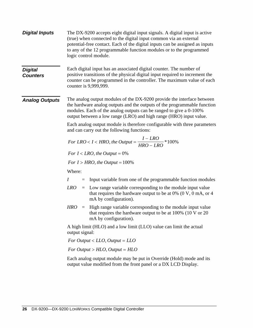
The analog output modules of the DX-9200 provide the interface between the hardware analog outputs and the outputs of the programmable function modules. Each of the analog outputs can be ranged to give a 0-100% output between a low range (LRO) and high range (HRO) input value.
Analog Outputs
Each analog output module is therefore configurable with three parameters and can carry out the following functions:
For LRO I HRO the OutputI LRO
HRO LRO< < =
−−
, *100%
For I LRO the Output< =, 0%
For I HRO the Output> =, 100%
Where: I = Input variable from one of the programmable function modules LRO = Low range variable corresponding to the module input value
that requires the hardware output to be at 0% (0 V, 0 mA, or 4 mA by configuration).
HRO = High range variable corresponding to the module input value that requires the hardware output to be at 100% (10 V or 20 mA by configuration).
A high limit (HLO) and a low limit (LLO) value can limit the actual output signal: For Output LLO Output LLO< =,
For Output HLO Output HLO> =,
Each analog output module may be put in Override (Hold) mode and its output value modified from the front panel or a DX LCD Display.
DX-9200—DX-9200 LonWorks Compatible Digital Controller 27
The DX-9200 controller provides four analog outputs, set to 0-10 V or 0-20 mA by jumper configuration (see Figure 9). These outputs may also be assigned a 4 mA zero offset via software configuration. In addition, the controller provides four outputs that are 0-10 V only.
The six logic output modules configure the six digital outputs (24 VAC triacs) of the DX-9200. The output modules provide the interface between the hardware digital outputs (triacs) and the outputs (logic or numeric variables) from the programmable function modules, programmable logic control module, or time scheduling modules. Any of these modules may be assigned to any of the logic output modules, and in turn each of the logic output modules controls its output triac.
Digital Outputs
A logic module may be put into Override (Hold) mode and its output value modified from the front panel or a DX LCD Display. Configure each logic output module to provide one of the following output types: On/off (driven from a logic variable)—The triac is switched on or
off by a change-of-state of the logic variable. On/off (driven from a numeric variable)—The triac is switched on
or off as a function of the output of a programmable function module (positive output = On, 0 or negative output = Off).
• Duration Adjusted Type (DAT) (driven from a numeric variable)—The triac is driven open or closed with a time base duty cycle that is proportional to the numeric output of a programmable function module. The DAT output can be ranged to give 0-100% duty cycle between a low range (LRO) and high range (HRO) value of the controlling variable.
Set a minimum on/off time, in percent of the time base, to avoid very short On pulses at the low range value (output at 0 %) and very short Off pulses at the high range value (output at 100 %).
Position Adjust Type (PAT, incremental control), without feedback (driven from a numeric variable)—A pair of triacs (two adjacent output modules) can be used as a Position Adjust Type (PAT) output to operate a synchronous reversible electric actuator.
PAT output gives modulating control by reference to the programmed actuator total run-time (fully open to fully closed), and drives the actuator for a part of that time base in proportion to the change in the controlling numeric variable. For example, for a 120-second actuator to achieve 40% open, the actuator will run for 48 seconds from a fully closed position.
Set a deadband, in percent of total run time, to avoid driving the actuator for very small changes in the output signal. This reduces unnecessary wear on the drive mechanism.
28 DX-9200—DX-9200 LONWORKS Compatible Digital Controller
Program the output to give 0-100% between a low range (LRO) and high range (HRO) of the value of the controlling variable.
Limit the travel of the actuator by entering low and high limits for the output signal (LLO and HLO).
A PAT output requires two output modules. The triac of the output module that is programmed as a PAT type switches on when the output must increase. The next output module (in numerical sequence) cannot be used for any other output function, and its triac switches on when the output must decrease. Modules 3/4, 4/5, 5/6, 6/7, and 7/8 can be used as PAT Type output.
When a PAT module is at 0% or 100%, the appropriate output triac switches on for the full stroke time every two hours.
PAT with feedback (driven from a numeric variable)—This output is identical to the above with the exception that a 0-100% analog position feedback signal is input into the controller and the actuator is driven in the appropriate direction until the position feedback signal is equal to the controlling variable position signal plus or minus the deadband value. A logic variable, which can be used for information or control purposes, is set if the feedback signal does not change when the actuator is driven in either direction.
Start/Stop (S/S) (driven from a logic variable)—A pair of triacs (two adjacent output modules) can be used as a start/stop output to operate an external latching circuit, which controls the starting and stopping of a pump, fan, etc. A start/stop output requires two output modules.
The triac of the output module that is programmed as an S/S type switches on for one second when the connected logic variable goes to state “1” (true). The next output module (in numerical sequence) must not be programmed and its triac switches on for one second when the connected logic variable goes to state “0” (false). Modules 3/4, 4/5, 5/6, 6/7, and 7/8 can be used as S/S type output.
Pulse (driven from a logic variable)—The triac switches on for a period of one second for each state transition of the connected logic variable.
There are 8 analog constants (ACO) and 32 digital constants (DCO), which can be used to store values set by the service module, front panel, or a DX LCD Display. Use these constants in the configuration in the same way that you would use analog inputs and numeric variables, and digital inputs and logic variables.
Analog/Digital Constants and Logic Result Status
DX-9200—DX-9200 LonWorks Compatible Digital Controller 29
There are 64 logic result status (LRS) variables that can be read by the service module or connected to network variables, and are used in the programmable logic control (PLC) module as program logic variables, partial logic results, or final logic results of logic routines. Use the logic result status variables in the configuration in the same way that you would use other logic variables.
If additional input/output points are necessary, extend the capacity of the DX-9200 controller by connecting up to eight extension modules via the XT Bus.
Extension Modules
An extension module comprises an XT-9100 or an XTM-905 processor/communications module and one or more XP expansion modules. The expansion modules provide input/output capability for the extension modules. The following are available for the XT-9100 extension module. Only those in boldface type are available in North America.
XP-9102: six analog inputs and two analog outputs XP-9103: eight digital outputs (triac) XP-9104: four digital inputs and four digital outputs (triac) XP-9105: eight digital inputs XP-9106: four digital outputs (relay) XP-9107: four digital outputs (relay) (North America)
Refer to the XT-9100 Technical Bulletin (LIT-6364040) for full details of these modules. The following are some examples of expansion module types available for the XTM-905 extension module. Only those in boldface type are available in North America. For a complete listing of all available expansion modules, see Table 10 in the Specifications and Technical Data section of this document.
XPA-421-5: four analog inputs XPA-442-5: four analog outputs with manual override XPA-821-5: six analog inputs and two analog outputs
(equivalent to XP-9102) XPB-821-5: eight digital (binary) inputs
(equivalent to XP-9105) XPM-401-5: four digital inputs and two digital outputs
(momentary relay pair with manual override) XPL-401-5: four binary inputs, three binary outputs
(latching relays with manual override) XPE-401-5: four digital inputs, three digital outputs
(electrically maintained relays with manual override)
30 DX-9200—DX-9200 LONWORKS Compatible Digital Controller
XPE-404-5: four digital inputs, four digital outputs (common supply) (electrically maintained relays with manual override, software configurable as On/Off or Pulse type)
XPE-444-5: four digital outputs (common supply) (On/Off or Pulse type relays with manual override)
XPT-401-5: four digital inputs, four digital outputs (24 VAC triacs with manual override; equivalent to XP-9104)
XPT-861-5: eight digital outputs (24 VAC triacs without manual override; equivalent to XP-9103)
Refer to the XTM-905 Extension Module, XPx-xxx Expansion Modules Technical Bulletin (LIT-6364210) for details of these modules and their respective ordering codes. An XT-9100 or XTM-905 can be combined with its expansion modules to provide the following configurations:
eight analog inputs/outputs or
eight digital inputs/outputs, with digital counters associated with the digital inputs
or eight analog inputs/outputs and eight digital inputs/outputs
or sixteen digital inputs/outputs, with digital counters associated with the
digital inputs within the first eight input/output points Note: When an extension module is configured with
sixteen inputs/outputs, it takes the place, in the DX-9200 database, of two extension modules with eight inputs/outputs each. The DX-9200 can communicate with a maximum of 64 inputs and outputs.
Analog inputs to extension modules may be 0-10 V, 0-20 mA, passive RTD-Ni1000 (JCI characteristic only), Pt1000, or A99 sensors. Voltage and current inputs from differential pressure transducers can be linearized by a square root function. Each analog input can be assigned to any of the 12 programmable function modules, and high and low alarm settings can be entered to each analog input. Digital inputs to extension modules are potential-free contacts. The input is active (true) when the contact is closed. Each digital input can be assigned to any of the 12 programmable function modules or to the programmable logic control module.
DX-9200—DX-9200 LonWorks Compatible Digital Controller 31
Digital counters are available in extension modules without analog inputs or outputs. Digital counters are associated with digital inputs. The number of positive transitions of the physical digital input required to increment the counter can be programmed in the extension module. Analog outputs in extension modules provide 0-10 V, 0-20 mA, or 4-20 mA, depending on the configuration. They connect to outputs of programmable function modules in the DX-9200 controller. The output is ranged by low range and high range variables to provide a 0-100% signal to the extension module. Digital outputs in extension modules are only configurable as On/Off or Pulse type. The physical output is a triac or a relay contact, depending on the model. Pulse type outputs switch on for a configurable period (5 to 1275 ms) for each transition of the connected variable. The exceptions are the XPM-421-5, XPL-401-5, and XPE-401-5 modules with relay outputs, which operate according to the type of module and have no equivalent in the XT-9100 set of XP modules. The digital outputs of the extension modules do not have the logic output control options of the DX controller digital outputs. Any of the following variables may drive the digital outputs:
• any logic variable or output of the programmable function modules
• any logic variable or output of the time schedule modules
• Logic Result (LRS) variables set by the Programmable Logic Control (PLC) module.
Note: For further information about extension modules, refer to the XT-9100 Technical Bulletin (LIT-6364040) and the XTM-905 Extension Module, XPx-xxx Expansion Modules Technical Bulletin (LIT-6364210).
Network Inputs/Outputs Introduction The DX-9200 controllers send and receive all data over the LONWORKS
network using the LONMARK network variables. Each model in the series has a fixed set of LONMARK network variables designed for a particular type of application. Because LONWORKS technology only uses metric units in the network variable data, a different DX-9200 model is required when the local panel data display (integral LED display or DX LCD Display, DT-9100) must display standard units (°F, CFM, in. W.C., etc.). Refer to Ordering Codes for the available models and Network Variable Internal Mapping Tables for details of the LONMARK network variables in each model.
32 DX-9200—DX-9200 LONWORKS Compatible Digital Controller
The LONMARK network variables are used both for peer-to-peer communication and for supervisory system monitoring and control. There is no access to the internal items in the DX-9200 controller through the LONWORKS network interface. The Metasys NCM350 (NCM361 in Europe) may be connected to the network as a supervisory system but it acts only as a supervisory controller and does not take part in the exchange of data between controllers. For details of the mapping possibilities of the LONMARK network variables to objects in the Metasys facility management system, refer to the LONWORKS Compatible Devices Supported by NCM350 Technical Bulletin (LIT-1162100). The LONMARK network variables pass data to the DX-9200 input/output and programmable modules via the internal network input/output items. These network input/output items are the same as those in the DX-9121 controller (refer to DX-9100 Configuration Guide [LIT-6364030]), and can be connected to other module items in the controller in the normal way with the GX-9100 Software Configuration Tool. The difference in the DX-9200 controller is that the internal network input/output items are mapped in a very specific way to the LONMARK network variables, and the LONMARK network variables represent specific types of data. In LONWORKS, each network variable has a data type defined by its associated SNVT (Standard Network Variable Type). For example, the variable type SNVT_temp_p transmits temperature values in degrees Celsius over the LONWORKS network. Some variable types have more than one element (or data field) and each element has been mapped to one internal network input or output item. For example, the variable type SNVT_switch has two elements, an integer element representing an analog percentage value and an integer element representing one of three states (Off, On, and Invalid); the first element is mapped to an analog network input/output item (NAIn or NAOn) and the second element is mapped to a digital network input/output item (NDIn or NDOn). Other variable types have a number of enumerated states and each state has been mapped to one bit of a digital network input/output item. The coordination of the values of the elements or enumerated states must be handled in the software configuration of the controller. In DX-9200 controllers for American data units, the analog values in the controller items must be in American units, and the controller converts the values into metric units for transmission over the LONWORKS network. Another major difference between the DX-9200 controller and the DX-9121 controller is that the peer-to-peer communication between controllers cannot be defined in the GX Tool. The Destination Items for Network Analog Outputs (NAOn) and Network Digital Outputs (NDIn) are not used. Instead, the LONWORKS network must be configured for peer-to-peer communication by a third party LONWORKS network configuration tool. The advantage of this is that the DX-9200 controller can be used in an “open” LONWORKS network and can be configured to send and receive data from third-party devices as well as other DX-9200 controllers.
DX-9200—DX-9200 LonWorks Compatible Digital Controller 33
For an introduction to LONWORKS technology, including details of LONMARK network variables, see the LONWORKS Network Layout Technical Bulletin (LIT-1162150). For more information on LONWORKS technology, contact the LONMARK Interoperability Association (www.lonmark.org) or Echelon® Corporation (www.echelon.com).
Analog Inputs (AI)
The DX-9200 controller uses up to 16 network AI, depending on the controller model, each of which holds a numerical value received from the LONMARK network variable to which it is mapped. These inputs can be used in the controller software configuration in the same way as physical inputs, except that there are no parameters to define. A typical application for a network analog input would be for receiving the value of the outdoor temperature from another controller or a setpoint from a supervisory system.
Digital Inputs The DX-9200 controller uses up to eight network digital module inputs, each containing 16 digital input logic values, depending on the controller model. The inputs receive each logic value from the LONMARK network variable to which it is mapped. These inputs can be used in the controller software configuration in the same way as physical digital inputs. A typical application for a network digital input might be for receiving operating status data from a primary unit so that a secondary unit can start when the load is high or the primary units fails, or for receiving a start signal from a supervisory system.
Analog Outputs (AO)
The DX-9200 controller uses up to 16 network AO, depending on the controller model, each of which holds a numerical value for transfer to the LONMARK network variable to which it is mapped. These network outputs receive their values from analog inputs, outputs, constants, programmable function modules, or extension modules in the same controller. The value is sent to other controllers or devices on the network via the LONMARK network variable. A typical application for a network output would be for sending the outdoor temperature value to another controller, or for making the value available for a supervisory system to read and display at a workstation.
Digital Outputs The DX-9200 controller uses up to eight network digital module outputs, each containing sixteen digital output logic values, depending on the controller model. Each logic value is transferred to the LONMARK network variable to which it is mapped. These network outputs receive their values from digital inputs, outputs, constants, logic result status, programmable function modules, time scheduling modules, or extension modules in the same controller. The value is sent to other controllers or devices on the network via the LONMARK network variable. A typical application for a network digital output would be for sending the occupancy status of the building or area to another controller in the same area, or for making the
34 DX-9200—DX-9200 LONWORKS Compatible Digital Controller
value available for a supervisory system to read and display at a workstation.
DX-9200—DX-9200 LonWorks Compatible Digital Controller 35
Operation
The DX-9200 provides realtime functions, 12 programmable function modules, and one programmable logic control module.
Introduction
The realtime functions are dedicated to the management of all the features related to the calendar and the time information. The following realtime modules are implemented:
Eight Time Schedule modules, each with eight On/Off events Two Optimal Start/Stop modules
The function of each programmable function module depends on the algorithm selected for that module. The following programmable algorithms are implemented in the DX-9200 operating system:
PID Controller On/Off Controller Heating/Cooling PID Controller (Dual PID) Heating/Cooling On/Off Controller (Dual On/Off) Average Calculation Minimum/Maximum Selection Psychrometric Calculation (Celsius/Fahrenheit) Line Segment Function (16 Segment) Input Selector Calculator (Linear or Polynomial Equation) Timer Functions (Eight Channels) Totalization (Event, Integration, Run Time) (Eight Channels) Comparator (Eight Channels) Sequencer (Up to Eight Output Stages) Four Line Segment Function (Four Functions with Four Segments
each) Eight Calculator (Eight Channel with Simple Math Function)
36 DX-9200—DX-9200 LONWORKS Compatible Digital Controller
The function of the programmable logic control module depends on a user-entered program of up to 512 program lines, each containing a field for an instruction code. The following instruction codes are implemented in the DX-9200 operating system: AND/AND NOT Logic AND/AND NOT OR/OR NOT Logic OR/OR NOT ANDB Logic AND between logic blocks ORB Logic OR between logic blocks OUT/OUT NOT Result transfer/Inverted result transfer COS Change-of-state detection SET/RST SET state to 1/RESET state to 0
In the GX-9100 Graphic Configuration Software, the program code is automatically generated from a graphic representation of the logic functions.
The realtime functions are based on a hardware realtime clock and on software tasks, which perform all the calendar and time functions, the daylight saving time changes, the day of the week definition, and the handling of holidays.
Realtime Functions
The realtime clock has a battery backup so it retains the correct time during a power (mains) failure. The clock parameters (year, month, day, hour, minute) can be set from both the front panel and a LONWORKS compatible supervisory system. The actual day of the week is automatically calculated from the calendar day during power-up initialization and at every change of date. A daylight saving function provides the automatic modification of the realtime clock, setting the time forward one hour when daylight saving time begins and setting the clock back one hour when it ends. The daylight saving period begins at time 00:00 on the begin date and terminates at 01:00 on the end date. An Exception Day Table determines exceptions for the day of the week status. These exceptions are normally used to define holidays. The Exception Day Table comprises up to 30 entries, each of which defines a time period with a begin date and an end date. If the actual date is within an exception day time period, the day type is set to “Holiday” (or Day Type 8).
DX-9200—DX-9200 LonWorks Compatible Digital Controller 37
Time Schedule Modules
The eight time schedule modules provide the control of a logic output as a function of a programmable start/stop schedule, the day of the week, exception days condition, and the realtime clock. The time schedule module is executed each minute. If external forcing conditions are not present then the module examines the event schedule to verify whether a start/stop command is programmed for the actual time and day of the week. Three logic inputs can modify the normal behavior of the time schedule module according to the following priorities: 1. A forcing command sets the output to Off. 2. A forcing command sets the output to On. 3. An extension override command extends the occupancy period for a
programmable time and is active only during occupancy time. A keyboard command or a command from a DX LCD Display also control the extension override status of the module. When any one of the commands from the keyboard, DX LCD Display, or logic input are true, the extension override status of the module is true. The time schedule module can contain up to eight events. Each entry contains the following information: DAYS ENABLE: to select in which days of the week (1 = Mon., 2 = Tue.,
up to 8 = holiday) the Start/Stop command is enabled; the command may be enabled for one or more days.
START TIME: [Hour][Minute] STOP TIME: [Hour][Minute] The duration of a time-programmed event can be extended to cover a period greater than one day by programming the stopping time of one event as 24:00 and the starting time of the next event as 00:00 on the next day. A time schedule module may be put in Override (Hold) mode and its logic output modified from the front panel or a DX LCD Display.
38 DX-9200—DX-9200 LONWORKS Compatible Digital Controller
Optimal Start/Stop Modules
Two optimal start/stop modules calculate the minimum time needed to bring a controlled zone temperature to a desired level at occupancy time under heating and/or cooling conditions. The modules also calculate the optimal stop time necessary to maintain the desired conditions up to the end of the occupancy time. The optimal start algorithm adapts as the heating and cooling thermal characteristics of the building are measured during the preheating or precooling cycles. The algorithm optionally compensates for outdoor temperatures above or below building design parameters. The optimal stop algorithm uses the given heating and cooling characteristics and outdoor temperature at the time of plant shutdown. If the outdoor temperature is not connected the optimal Stop mode is automatically disabled. The optimal start modules are defined by the following parameters:
Zone Temperature Outdoor Temperature Zone Temperature On Setpoint (20)* [°C] or (68)* [°F] Zone Temperature Stop mode (Off) Bias (-3)* [°C] or (-6)* [°F] Time Schedule Module connections External Disable Signal to the Adapting Algorithm External Disable Signal to the Module Module type: Heating, Cooling, Heating and Cooling Minimum Heat/Cool Time (20)* [minutes] Maximum Startup Time (240)* [minutes] Maximum Optimal Stop Time (240)* [minutes] Start mode Building Heating Factor (5)* [min/°C²] or (1)* [min/°F²] Start mode Building Cooling Factor (5)* [min/°C²] or (1)* [min/°F²] Stop mode Building Heating Factor (100)* [min/°C/°C] or (100)*
[min/°F/°F] Stop mode Building Cooling Factor (100)* [min/°C/°C] or (100)*
[min/°F/°F] Adaptive Control (Filter Weight) (10)* [%] Outdoor Air Design Temp. Heating (-10)* [°C] or (23)* [°F] Outdoor Air Design Temp. Cooling (30)* [°C] or (86)* [°F] Control Range (+/-) (2)* [°C] or (4)* [°F]
*Default value in the Graphic Programming software
DX-9200—DX-9200 LonWorks Compatible Digital Controller 39
The parameters Zone Temperature On Setpoint and Zone Temperature Off Setpoint Bias may be set as fixed values or they may be connected to other numerical values in the configuration.
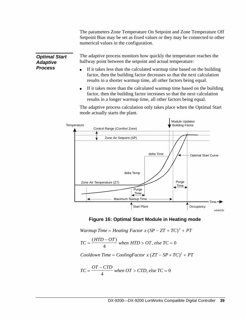
The adaptive process monitors how quickly the temperature reaches the halfway point between the setpoint and actual temperature:
Optimal Start Adaptive Process If it takes less than the calculated warmup time based on the building
factor, then the building factor decreases so that the next calculation results in a shorter warmup time, all other factors being equal.
If it takes more than the calculated warmup time based on the building factor, then the building factor increases so that the next calculation results in a longer warmup time, all other factors being equal.
The adaptive process calculation only takes place when the Optimal Start mode actually starts the plant.
Temperature
delta Time
delta Temp
Optimal Start Curve
Control Range (Comfort Zone)
Zone Air Setpoint (SP)
Zone Air Temperature (ZT)
OccupancyStart Plant
Module UpdatesBuilding Factor
PurgeTime
PurgeTime
Maximum Startup Time
edxtb22b
Time
Figure 16: Optimal Start Module in Heating mode
Warmup Time Heating Factor x SP ZT TC PT= − +( )2 +
TCHTD OT
when HTD OT else TC=−
> =( )
,4
0
Cooldown Time CoolingFactor x ZT SP TC PT= − +( )2 +
TCOT CTD
when OT CTD else TC=−
> =4
0,
40 DX-9200—DX-9200 LONWORKS Compatible Digital Controller
When the Zone Air Temperature has risen halfway towards the Zone Setpoint, the module updates the Building Factor value using the following calculation:
NBFFW x OF FW x delta Time delta Temp
=− +( /100
100
2( )
The module does not update the Building Factor if the initial Zone Air Temperature is within the Control Range, or the Outdoor Temperature is outside of design values.
• NBF = New Building Factor
• FW = Filter Weight
• OF = Old Factor
• SP = Zone Air Setpoint Temperature
• ZT = Zone Air Temperature
• PT = Minimum Heat/Cool Time (Purge Time)
• HTD = Outdoor Design Temperature Heating
• CTD = Outdoor Design Temperature Cooling
• TC = Temperature Compensation • OT = Outdoor Temperature
DX-9200—DX-9200 LonWorks Compatible Digital Controller 41
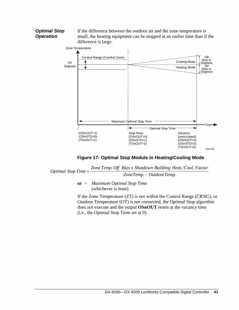
Optimal Stop Operation
If the difference between the outdoor air and the zone temperature is small, the heating equipment can be stopped at an earlier time than if the difference is large.
Zone Temperature
TimeOptimal Stop Time
OnSetpoint
Off
Bias in
DegreesOff
Bias in
Degrees
Maximum Optimal Stop Time
Stop Plant(OSnOUT=0)(OSnSTO=1)(TSnOUT=1)
Vacancy(unoccupied)(OSnOUT=0)(OSnSTO=0)(TSnOUT=0)
Cooling Mode
Heating Mode
(OSnOUT=1)(OSnSTO=0)(TSnOUT=1)
Control Range (Comfort Zone)
dxhcmtb
Figure 17: Optimal Stop Module in Heating/Cooling Mode
Optimal Stop TimeZone Temp Off Bias x Shutdown Building Heat Cool Factor
ZoneTemp OutdoorTemp=
−. .
. ./ .
or = Maximum Optimal Stop Time (whichever is least). If the Zone Temperature (ZT) is not within the Control Range (CRNG), or Outdoor Temperature (OT) is not connected, the Optimal Stop algorithm does not execute and the output OSnOUT resets at the vacancy time (i.e., the Optimal Stop Time set at 0).
42 DX-9200—DX-9200 LONWORKS Compatible Digital Controller
Programmable Function Modules: Control Algorithms
The DX-9200 has four control algorithms: PID controller On/Off controller Heating/Cooling PID controller (Dual PID) Heating/Cooling On/Off controller (Dual On/Off)
Each algorithm can be used in one of the 12 programmable function modules. The four algorithms have a number of operating modes that are a function of the operating parameters and digital inputs. These operating modes are as follows:
Comfort mode: This is used to obtain the desired space temperature typically during occupancy. The setpoints in this mode mark the beginning of demand for heating or cooling. The control algorithm calculates the output using the following value as the working setpoint:
)( RSPLSPxRVWSP +=
Standby mode: When operating in this mode, the controller setpoint decreases or increases during heating or cooling, respectively, when it is compared with the Comfort mode setpoint. This mode is typically selected for brief periods when the controlled zone is unoccupied in order to save energy. The control algorithm calculates the output using the following value as the working setpoint:
WSP RV x LSP RSP BSB= + +( )
Off mode: This is similar to the Standby mode, but the setpoint is further reduced or increased when the controlled zone is unoccupied for long periods. This mode is typically selected for nights, weekends, or vacations, etc. The control algorithm calculates the output using following value as the working setpoint:
WSP RV x LSP RSP BOF= + +( )
External Forcing mode: The control module output assumes a configured value, overriding the output limits of the control module.
The above modes can be selected through digital inputs or through digital constants, depending on the configuration. High and low limit values for WSP can be set in the configuration to limit the calculated value for WSP and any overridden value of WSP to within an acceptable working range.
DX-9200—DX-9200 LonWorks Compatible Digital Controller 43
The following modes are also supported by the DX-9200 controller: HLD Hold mode (module output value (OCM) is no longer
calculated by the algorithm, and may be overridden from the front panel or DX LCD Display).
REM Remote mode (working setpoint is determined only by the remote setpoint). Remote mode is set by a configuration parameter.
The following operating modes are not supported by the DX-9200 controller:
CMP Computer mode STA Startup mode SOF Shutoff mode
Algorithm 1 - PID Control
Each of the 12 programmable function modules can be defined as a PID (Proportional, Integral, and Derivative) control module. The proportional control module generates an output (OCM) ranging between 0 and 100% by comparing the Process Variable (PV) with the Working Setpoint (WSP) and the Proportional Band (PB). During configuration, enter the Proportional Band (PB) as a percentage of the programmed range of the PV. It determines the operating range of the control module. A positive value for a PB selects direct acting and a negative value for a PB selects reverse acting. For example, a PV input range of 0-40 °C and a PB setting of 15% result in a direct acting controller with a proportional band of 6 Kelvin. When the PV does not have a programmed range (PV@ is not connected to an analog input), a range of 0-100 is assumed. The PI, PD, or PID action of a control module is determined by setting the appropriate values of reset action (TI) and rate action (TD) in the control module settings. The reset action (TI) represents the integral time and is definable between 0 and 60 repeats per minute. A value of 0 disables the integral action. Integral action time Tn = 1/TI minutes The rate action (TD) represents the derivative action decay time and is definable between 0 and 5 minutes. A value of 0 disables the derivative action. The controller output can be generally described by a three zone function: two static zones defined by a low limit (LOL) and a high limit (HIL), and a dynamic zone where the output is the function of proportional band, reset action, and rate action. The output can be connected directly to an output module, or used as an input to one or more other programmable function modules (for example, to obtain cascade control).
44 DX-9200—DX-9200 LONWORKS Compatible Digital Controller
Hold
F (Modes,BSB,BOF)
PB
PVRV
RS
LSP
OF
SBRA
OB@PB@
PV@RV@
RS@
OF@SB@
RA@
EF@ EF
f=(PB,TI,TD,EDB)
WSP
OB
HHDA HDA LDA CML EF STA SOF HOLD
OCMOutput
LLDA CMH
REM
emdxtb24
Limiting
and
Forcing
HIL LOL
Figure 18: Control Module Block Diagram
Control Module Inputs and Outputs
The PID algorithm can be configured by using a number of analog and logic variables. As part of its operating function it also provides a number of logical outputs to be used for interlocking or alarm purposes. Below is a list of these variables:
Numeric Input Variable Connections
PB@ defines the source of the proportional band. If the input is not connected, the internal value PB is used.
PV@ defines the source of the process variable. It is typically a pressure, temperature, or humidity input, which, as it varies, causes the control module to change its output according to its PID transfer function.
RV@ defines the source of the reference variable. This input causes the control module to perform as a ratio controller. Its effect is a multiplication factor in the working setpoint calculation. If not connected, a default value of 1 is assumed.
RS@ defines the source of a remote setpoint. This input produces a bias on the local setpoint. If not connected, a default value of 0 is assumed.
OB@ defines the source of the output bias. If the input is not connected, the internal value OB is used.
DX-9200—DX-9200 LonWorks Compatible Digital Controller 45
Logic Input Variable Connections
OF@ defines the source of a digital input that forces the control module to the Off mode. If not connected, the Off mode is disabled.
SB@ defines the source of the digital input that puts the control module to the Standby mode. If not connected, the Standby mode is disabled.
RA@ defines the source of the digital input that causes the control module action to be reversed. If not connected, the control action change function is disabled.
EF@ defines the source of the digital input that forces the control module to the External Forcing mode. If not connected, the function is disabled.
Logic Output States
CMH: Output of control module has reached its high limit. CML: Output of control module has reached its low limit. HHDA: High High Deviation Alarm. (PV - WSP) is greater than the
high high deviation alarm value. HDA: High Deviation Alarm. (PV - WSP) is greater than the high
deviation alarm value. LDA: Low Deviation Alarm. (WSP - PV) is greater than the low
deviation alarm value. LLDA: Low Low Deviation Alarm. (WSP - PV) is greater than the
low low deviation alarm value. EF: When this state is On, the module is being externally forced. STA: not used. SOF: not used. HLD: When this state is On, the module is in Hold mode. CMP: not used. OF: When this state is On, the module is in Off mode. SB: When this state is On, the module is in Standby mode. RA: When this state is On, the module is in Reverse Action mode.

46 DX-9200—DX-9200 LONWORKS Compatible Digital Controller
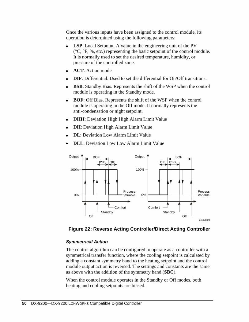
Once the various inputs have been assigned to the control module, its operation is determined using the following parameters:
LSP: Local Setpoint. A value in the engineering unit of the PV (°C, °F, %, etc.) representing the basic setpoint of the control module. It is normally used to set the desired temperature, humidity, or pressure of the controlled zone.
PB: Proportional Band TI: Reset Action (PI, PID) TD: Rate Action (PD, PID) BSB: Standby Bias. Represents the shift of the WSP when the control
module is operating in the Standby mode. BOF: Off Bias. Represents the shift of the WSP when the control
module is operating in the Off mode. It normally represents the anti-condensation or night setpoint.
EDB: Errordeadband. Expressed in % of proportional band. When the control variation (PV-WSP) is smaller than the Errordeadband, then the integral action of the controller is not active.
DHH: Deviation High High Alarm Limit Value DH: Deviation High Alarm Limit Value DL: Deviation Low Alarm Limit Value DLL: Deviation Low Low Alarm Limit Value HIL: Upper limit of the controller output OCM LOL: Lower limit of the controller output OCM OB: Output Bias. Represents a constant value that is added to the
controller output OCM.
0%
100%
Output
ProcessVariable
0%
100%
Output
ProcessVariable
BOFBSBPB
BOFBSB PB
StandbyComfort
Off
emdxtb25
High Limit(HIL)
High Limit(HIL)
Low Limit(LOL)
StandbyComfort
Off
Low Limit(LOL)
Figure 19: Reverse Acting Controller/Direct Acting Controller
DX-9200—DX-9200 LonWorks Compatible Digital Controller 47
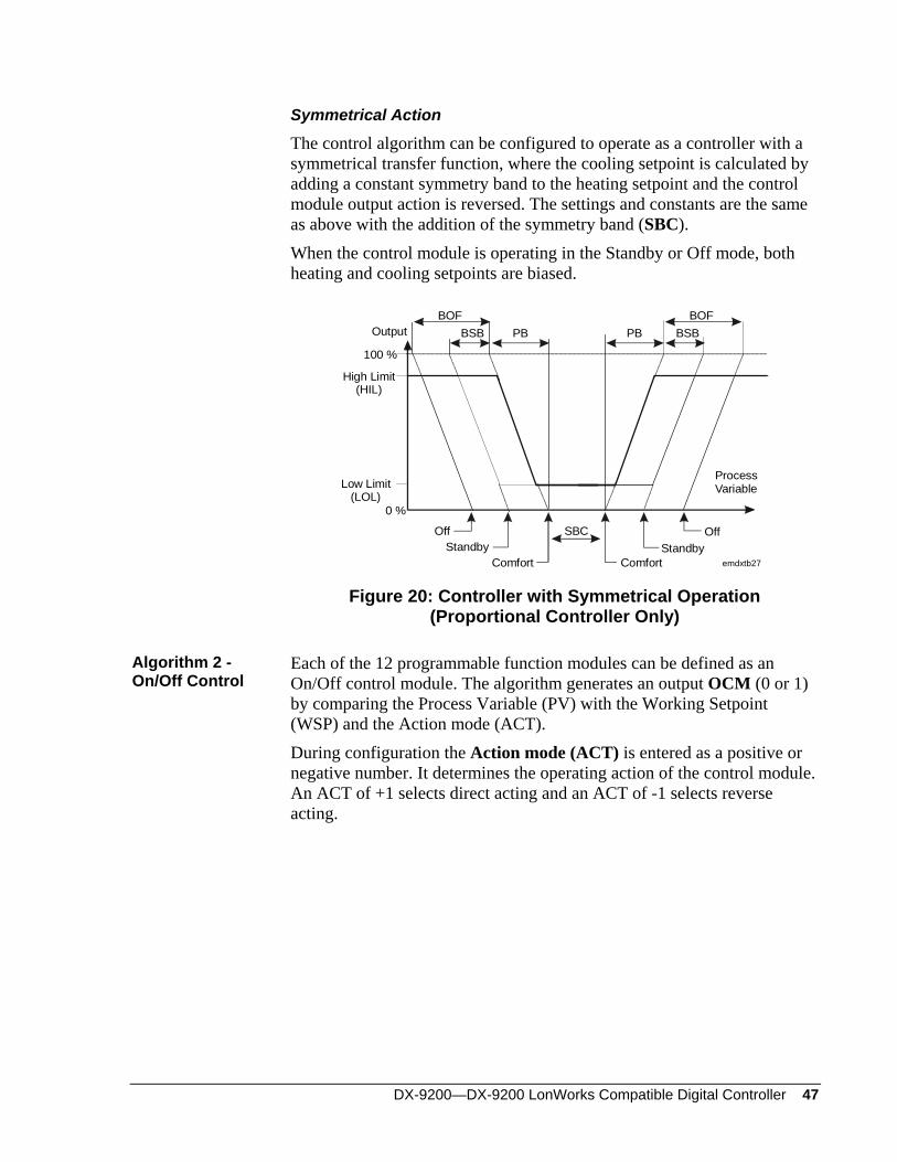
Symmetrical Action
The control algorithm can be configured to operate as a controller with a symmetrical transfer function, where the cooling setpoint is calculated by adding a constant symmetry band to the heating setpoint and the control module output action is reversed. The settings and constants are the same as above with the addition of the symmetry band (SBC). When the control module is operating in the Standby or Off mode, both heating and cooling setpoints are biased.
PB
ComfortStandby
Comfort
Off
0 %
100 %
OutputBOF BOF
BSB BSBPB
emdxtb27
SBC
ProcessVariable
StandbyOff
High Limit(HIL)
Low Limit(LOL)
Figure 20: Controller with Symmetrical Operation (Proportional Controller Only)
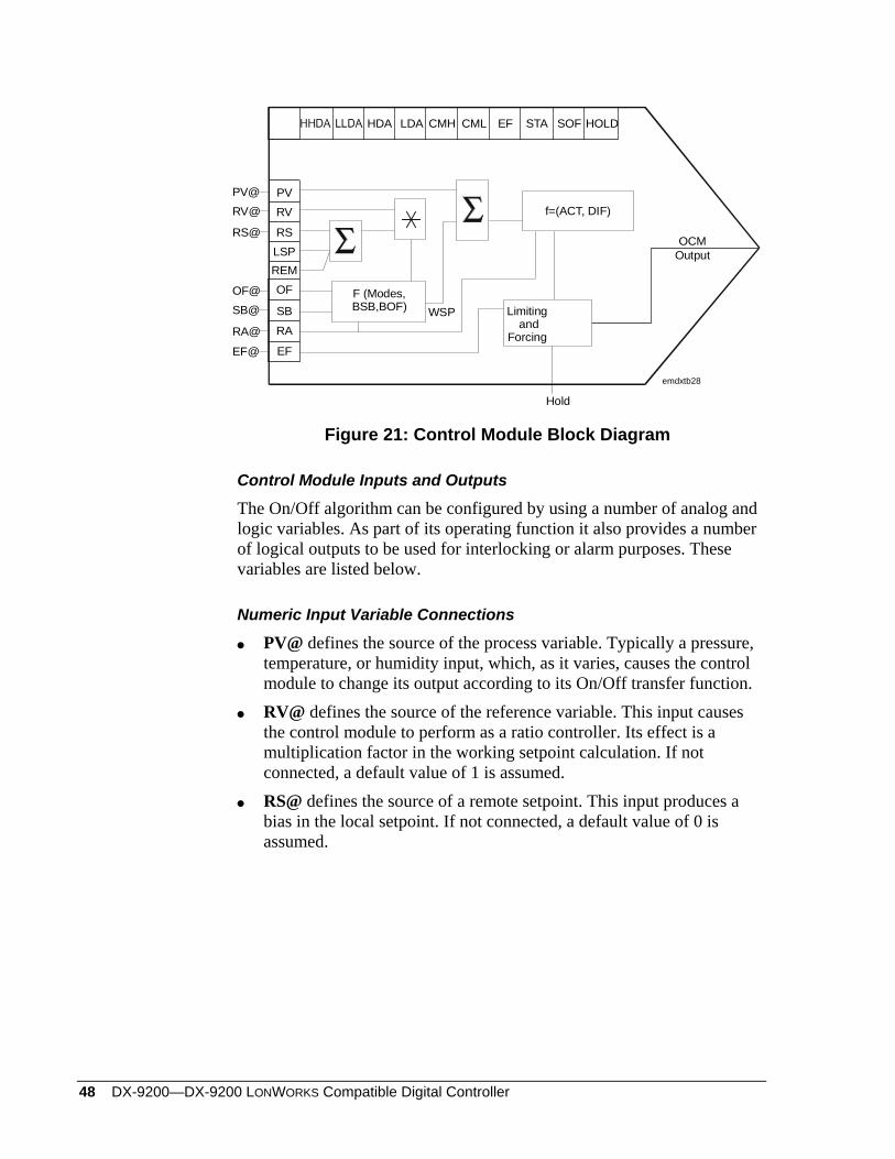
Algorithm 2 - On/Off Control
Each of the 12 programmable function modules can be defined as an On/Off control module. The algorithm generates an output OCM (0 or 1) by comparing the Process Variable (PV) with the Working Setpoint (WSP) and the Action mode (ACT). During configuration the Action mode (ACT) is entered as a positive or negative number. It determines the operating action of the control module. An ACT of +1 selects direct acting and an ACT of -1 selects reverse acting.
48 DX-9200—DX-9200 LONWORKS Compatible Digital Controller
Hold
F (Modes,BSB,BOF)
PVRV
RSLSP
OF
SBRA
PV@RV@
RS@
OF@SB@
RA@
EF@ EF
f=(ACT, DIF)
WSP
HDA LDA CML EF STA SOF HOLD
OCMOutput
CMH
REM
emdxtb28
Limiting and
Forcing
Figure 21: Control Module Block Diagram
Control Module Inputs and Outputs
The On/Off algorithm can be configured by using a number of analog and logic variables. As part of its operating function it also provides a number of logical outputs to be used for interlocking or alarm purposes. These variables are listed below.
Numeric Input Variable Connections
PV@ defines the source of the process variable. Typically a pressure, temperature, or humidity input, which, as it varies, causes the control module to change its output according to its On/Off transfer function.
RV@ defines the source of the reference variable. This input causes the control module to perform as a ratio controller. Its effect is a multiplication factor in the working setpoint calculation. If not connected, a default value of 1 is assumed.
RS@ defines the source of a remote setpoint. This input produces a bias in the local setpoint. If not connected, a default value of 0 is assumed.
DX-9200—DX-9200 LonWorks Compatible Digital Controller 49
Logic Input Variable Connections
OF@ defines the source of a digital input that forces the control module to the Off mode. If not connected, the Off mode is disabled.
SB@ defines the source of the digital input that puts the control module to the Standby mode. If not connected, the Standby mode is disabled.
RA@ defines the source of the digital input that causes the control module action to be reversed. If not connected, the function is disabled.
EF@ defines the source of the digital input that forces the control module to the External Forcing mode. If not connected, the function is disabled.
Logic Output States
• CMH: Output of control module has reached its high limit.
• CML: Output of control module has reached its low limit.
• HHDA: High High Deviation Alarm. (PV - WSP) is greater than the high high deviation alarm value.
• HDA: High Deviation Alarm. (PV - WSP) is greater than the high deviation alarm value.
• LDA: Low Deviation Alarm. (WSP - PV) is greater than the low deviation alarm value.
• LLDA: Low Low Deviation Alarm. (WSP - PV) is greater than the low low deviation alarm value.
• EF: When this state is On, the module is being externally forced.
• STA: not used.
• SOF: not used.
• HLD: When this state is On, the module is in Hold mode.
• CMP: not used.
• OF: When this state is On, the module is in Off mode.
• SB: When this state is On, the module is in Standby mode.
• RA: When this state is On, the module is in Reverse Action mode.
50 DX-9200—DX-9200 LONWORKS Compatible Digital Controller
Once the various inputs have been assigned to the control module, its operation is determined using the following parameters:
LSP: Local Setpoint. A value in the engineering unit of the PV (°C, °F, %, etc.) representing the basic setpoint of the control module. It is normally used to set the desired temperature, humidity, or pressure of the controlled zone.
ACT: Action mode DIF: Differential. Used to set the differential for On/Off transitions. BSB: Standby Bias. Represents the shift of the WSP when the control
module is operating in the Standby mode. BOF: Off Bias. Represents the shift of the WSP when the control
module is operating in the Off mode. It normally represents the anti-condensation or night setpoint.
DHH: Deviation High High Alarm Limit Value DH: Deviation High Alarm Limit Value DL: Deviation Low Alarm Limit Value
• DLL: Deviation Low Low Alarm Limit Value
0%
100%
Output
ProcessVariable
ProcessVariable
Comfort
emdxtb29
StandbyOff
BOFBSB DIF
ComfortStandby
Off
BOFBSBDIF
0%
100%
Output
Figure 22: Reverse Acting Controller/Direct Acting Controller
Symmetrical Action
The control algorithm can be configured to operate as a controller with a symmetrical transfer function, where the cooling setpoint is calculated by adding a constant symmetry band to the heating setpoint and the control module output action is reversed. The settings and constants are the same as above with the addition of the symmetry band (SBC). When the control module operates in the Standby or Off modes, both heating and cooling setpoints are biased.
DX-9200—DX-9200 LonWorks Compatible Digital Controller 51
0 %
100 %
Output
Comfortemdxtb31
StandbyOff
BOFBSB DIF
ProcessVariable
ComfortStandby
Off
BOFBSBDIF
SBC
Figure 23: On/Off Controller with Symmetric Operation (ACT = -1)
Algorithm 3 - Heating/Cooling PID Control
Each of the 12 programmable function modules can be defined as a Heating/Cooling PID (Proportional, Integral, and Derivative) Control Module. The algorithm is implemented with two PID control loops sharing the same process variable (PV) and output (OCM). The DX-9200 controller, the output of the heating control loop (OCM1), and the output of the cooling control loop (OCM2) are also available. The output ranges between 0 and 100%, comparing the process variable with a working setpoint (WSP) and the proportional band (PB1 and PB2) for each loop. During configuration the proportional bands PB1 and PB2 are entered as percentages of the programmed range of the PV and determine the operating ranges of the loops. A positive value of PB selects direct acting and a negative value of PB selects reverse acting. For the normal heating/cooling functions, PB1 is negative (-) and PB2 is positive (+). For example, a PV input range of 0-40 °C and a PB setting of 15% results in a proportional band of 6 Kelvin. When the PV does not have a programmed range (PV@ is not connected to an analog input), a range of 0-100 is assumed. The PI, PD, or PID action of a loop is determined by setting the appropriate values of reset action (TI1 and TI2) and rate action (TD1 and TD2) in the control module settings. The TI1 and TI2 reset action represents the integral time and is definable between 0 and 60 repeats per minute. A value of 0 disables the integral action. Integral action time Tn = 1/TI minutes The TD1 and TD2 rate action represents the derivative action decay time and is definable between 0 and 5 minutes. A value of 0 disables the derivative action.
52 DX-9200—DX-9200 LONWORKS Compatible Digital Controller
The controller output can be generally described by a three-zone function for each loop: two static zones defined by a low limit (LOL1 and LOL2) and a high limit (HIL1 and HIL2), and a dynamic zone where the output is the function of the respective proportional band, reset action, and rate action. The outputs can be connected directly to an output module, or used as an input to one or more other programmable function modules (for example, to obtain cascade control).
Control Module Inputs and Outputs
The Heating/Cooling PID algorithm can be configured by using a number of analog and logic variables. As part of its operating function it also provides a number of logical outputs to be used for interlocking or alarm purposes. A list of these variables follows.
Numeric Input Variable Connections
PB@ defines the source of the proportional band. If the input is not connected, the internal value PB1 or PB2 is used.
PV@ defines the source of the process variable. Typically a pressure, temperature, or humidity input, which, as it varies, causes the control module to change its output according to its PID transfer function.
RV1@/RV2@ defines the source of the reference variable or ratio for the respective loop. This input causes the control module to perform as a ratio controller. Its effect is a multiplication factor in the working setpoint calculation. If not connected, a default value of 1 is assumed.
RS1@/RS2@ defines the source of a remote setpoint for the respective loop. This input produces a bias on the local setpoint LSP1 or LSP2. If not connected, a default value of 0 is assumed.
OB1@/ OB2@ defines the source of the output bias of the respective loop. If the input is not connected, the internal value OB1/OB2 is used.
Logic Input Variable Connections
OF@ defines the source of a digital input that forces the control module to the Off mode. If not connected, the Off mode is disabled.
SB@ defines the source of the digital input that puts the control module to the Standby mode. If not connected, the Standby mode is disabled.
RA@ defines the source of the digital input that causes the control module action to be reversed. If not connected, the control action change function is disabled.
EF@ defines the source of the digital input that forces the control module to the External Forcing mode. If not connected, the function is disabled.
DX-9200—DX-9200 LonWorks Compatible Digital Controller 53
Logic Output States
CMH: Output of control module has reached its high limit. (Loop 1 or 2)
CML: Output of control module has reached its low limit. (Loop 1 or 2)
HHDA: High High Deviation Alarm. (PV - WSP) is greater than the high high deviation alarm value. (Loop 1 or 2)
HDA: High Deviation Alarm. (PV - WSP) is greater than the high deviation alarm value. (Loop 1 or 2)
LDA: Low Deviation Alarm. (WSP - PV) is greater than the low deviation alarm value. (Loop 1 or 2)
LLDA: Low Low Deviation Alarm. (WSP - PV) is greater than the low low deviation alarm value. (Loop 1 or 2)
EF: When this state is On, the module is being externally forced. STA: not used. SOF: not used. HLD: When this state is On, the module is in Hold mode. CMP: not used. OF: When this state is On, the module is in Off mode. SB: When this state is On, the module is in Standby mode. RA: When this state is On, the module is in Reverse Action mode. HEAT: When this state is On, the module is in Heating mode.
Once the various inputs have been assigned to the control module, its operation is determined using the following parameters for the respective control loops:
LSP1/LSP2: Local Setpoint. A value in the engineering unit of the PV (°C, °F, %, etc.) representing the basic setpoint of the respective loop. It is normally used to set the desired temperature, humidity, or pressure of the controlled zone.
PB1/PB2: Proportional Band. This parameter ranges from 0 to -100% for a heating loop and from 0 to +100% for a cooling loop.
TI1/TI2: Reset Action (PI, PID) TD1/TD2: Rate Action (PD, PID) BSB1/BSB2: Standby Bias. Represents the shift of the WSP when the
loop is operating in the Standby mode. BOF1/BOF2: Off Bias. Represents the shift of the WSP when the loop
is operating in the Off mode.
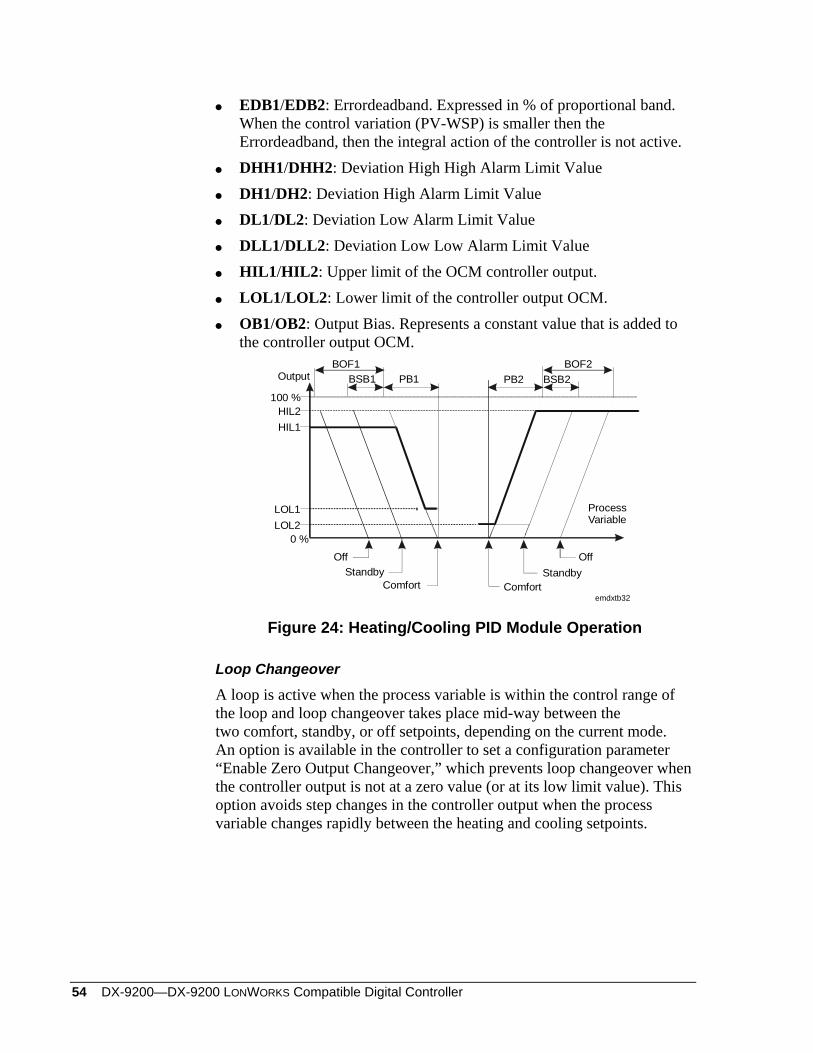
54 DX-9200—DX-9200 LONWORKS Compatible Digital Controller
EDB1/EDB2: Errordeadband. Expressed in % of proportional band. When the control variation (PV-WSP) is smaller then the Errordeadband, then the integral action of the controller is not active.
DHH1/DHH2: Deviation High High Alarm Limit Value DH1/DH2: Deviation High Alarm Limit Value DL1/DL2: Deviation Low Alarm Limit Value DLL1/DLL2: Deviation Low Low Alarm Limit Value HIL1/HIL2: Upper limit of the OCM controller output. LOL1/LOL2: Lower limit of the controller output OCM. OB1/OB2: Output Bias. Represents a constant value that is added to
the controller output OCM.
0 %
100 %
Output
ProcessVariable
BOF2BSB2PB2
BOF1BSB1 PB1
StandbyComfort
Off
emdxtb32
StandbyComfort
Off
HIL2HIL1
LOL1LOL2
Figure 24: Heating/Cooling PID Module Operation
Loop Changeover
A loop is active when the process variable is within the control range of the loop and loop changeover takes place mid-way between the two comfort, standby, or off setpoints, depending on the current mode. An option is available in the controller to set a configuration parameter “Enable Zero Output Changeover,” which prevents loop changeover when the controller output is not at a zero value (or at its low limit value). This option avoids step changes in the controller output when the process variable changes rapidly between the heating and cooling setpoints.
DX-9200—DX-9200 LonWorks Compatible Digital Controller 55
Algorithm 4 – Heating/Cooling On/Off Control
Each of the 12 programmable function modules can be defined as a Heating/Cooling On/Off Control Module. The algorithm is implemented with two on/off control loops sharing the same process variable (PV) and output (OCM). The output of the heating control loop (OCM1) and the output of the cooling control loop (OCM2) are also available. The algorithm generates an output of 0 or 1 by comparing the process variable (PV) with the working setpoint (WSP) and Action mode (ACT1/ACT2) for the respective loop. During configuration the Action mode (ACT1/ACT2) is entered as a positive or negative number. It determines the operating action of the respective loop. An ACT of +1 selects direct acting and an ACT of -1 selects reverse acting. For the normal heating/cooling functions, ACT1 is -1 and ACT2 is +1.
Control Module Inputs and Outputs
The Heating/Cooling On/Off algorithm can be configured by using a number of analog and logic variables. As part of its operating function it also provides a number of logical outputs to be used for interlocking or alarm purposes. Below is a list of these variables:
Numeric Input Variable Connections
PV@ defines the source of the process variable. It is typically a pressure, temperature, or humidity input, which, as it varies, causes the control module to change its output according to its On/Off transfer function.
RV1@ / RV2@ defines the source of the reference variable or ratio for the respective loop. This input causes the control module to perform as a ratio controller. Its effect is a multiplication factor in the working setpoint calculation. If not connected, a default value of 1 is assumed.
• RS1@ / RS2@ defines the source of a remote setpoint for the respective loop. This input produces a bias on the local setpoint LSP1/LSP2. If not connected, a default value of 0 is assumed.
56 DX-9200—DX-9200 LONWORKS Compatible Digital Controller
Logic Input Variable Connections
OF@ defines the source of a digital input that forces the control module to the Off mode. If not connected, the Off mode is disabled.
SB@ defines the source of the digital input that puts the control module to the Standby mode. If not connected, the Standby mode is disabled.
RA@ defines the source of the digital input that causes the control module action to be reversed. If not connected, the control action change function is disabled.
• EF@ defines the source of the digital input that forces the control module to the External Forcing mode. If not connected, the function is disabled.
Logic Output States
CMH: Output of control module has reached its high limit. (Loop 1 or 2)
CML: Output of control module has reached its low limit. (Loop 1 or 2)
HHDA: High High Deviation Alarm. (PV - WSP) is greater than the high high deviation alarm value. (Loop 1 or 2)
HDA: High Deviation Alarm. (PV - WSP) is greater than the high deviation alarm value. (Loop 1 or 2)
LDA: Low Deviation Alarm. (WSP - PV) is greater than the low deviation alarm value. (Loop 1 or 2)
LLDA: Low Low Deviation Alarm. (WSP - PV) is greater than the low low deviation alarm value. (Loop 1 or 2)
EF: When this state is On, the module is being externally forced. STA: not used.
• SOF: not used.
• HLD: When this state is On, the module is in Hold mode. CMP: not used. OF: When this state is On, the module is in Off mode. SB: When this state is On, the module is in Standby mode. RA: When this state is On, the module is in Reverse Action mode. HEAT: When this state is On, the module is in Heating mode.
DX-9200—DX-9200 LonWorks Compatible Digital Controller 57
Once the various inputs have been assigned to the control module, its operation is determined using the following parameters for the respective loops:
LSP1/LSP2: Local Setpoint. A value in the engineering unit of the PV (°C, °F, %, etc.) representing the basic setpoint of the control module. It is normally used to set the desired temperature, humidity, or pressure of the controlled zone.
ACT1/ACT2: Action mode DIF1/DIF2: Differential. Used to set the differential for On/Off
transitions. BSB1/BSB2: Standby Bias. Represents the shift of the WSP when the
control module is operating in the Standby mode. BOF1/BOF2: Off Bias. Represents the shift of the WSP when the
control module is operating in the Off mode. It normally represents the anti-condensation or night setpoint.
DHH1/DHH2: Deviation High High Alarm Limit Value DH1/DH2: Deviation High Alarm Limit Value DL1/DL2: Deviation Low Alarm Limit Value DLL1/DLL2: Deviation Low Low Alarm Limit Value
ProcessVariable0 %
100 %
Output
Comfortemdxtb33
StandbyOff
BOF1BSB1 DIF1
ComfortStandby
Off
BOF2BSB2DIF2
Figure 25: Heating/Cooling On/Off Module Operation
58 DX-9200—DX-9200 LONWORKS Compatible Digital Controller
Numeric Calculation Algorithms
Each of the 12 programmable function modules can be defined as a numeric calculation module, capable of executing a mathematical algorithm. Each module can accept up to eight inputs from the controller’s numerical and logic variables, and each module provides an output that can be connected to either a control or output module, the appropriate interconnections being carried out during configuration. Each of the 12 programmable function modules can be configured to perform one of the following algorithms:
Algorithm 11 - Average Calculation
This algorithm calculates the arithmetic average of up to eight connected inputs. Each input may be weighted with a constant K.
OutputI K I K I K
K=
+ + +1 1 2 2 80
* * ... * 8
In = Input Variable n= 1 to 8 Kn = Constant n = 0 to 8 The module output (NCM) can be limited by a low limit (LOL) and a high limit (HIL). When the module is in Hold mode, the algorithm does not update its numeric output. Only then can a DX LCD Display modify the output.
Algorithm 12 - Minimum Select
This algorithm selects the minimum value of up to eight input variables. Each input may be weighted with a constant K.
)8*8,...2*2,1*1.(0 KIKIKIMINKOutput +=
In = Input Variable n = 1 to 8 Kn = Constant n = 0 to 8 The module output (NCM) can be limited by a low limit (LOL) and a high limit (HIL). When the module is in Hold mode, the algorithm does not update its numeric output. Only then can a DX LCD Display modify the output.
Algorithm 13 - Maximum Select
This algorithm selects the maximum value of up to eight input variables. Each input may be weighted with a constant K.
)8*8,...2*2,1*1.(0 KIKIKIMAXKOutput +=
In = Input variable n = 1 to 8 Kn = Constant n = 0 to 8 The module output (NCM) can be limited by a low limit (LOL) and a high limit (HIL). When the module is in Hold mode, the algorithm does not update its numeric output. Only then can a DX LCD Display modify the output.
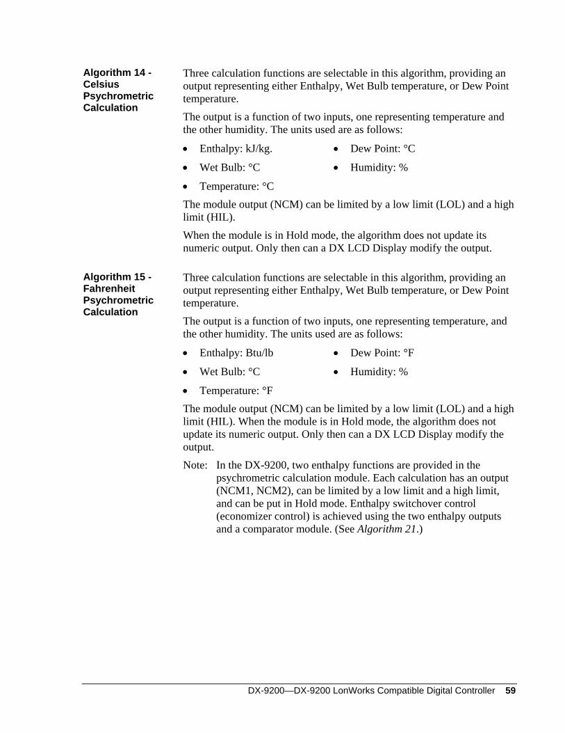
DX-9200—DX-9200 LonWorks Compatible Digital Controller 59
Algorithm 14 - Celsius Psychrometric Calculation
Three calculation functions are selectable in this algorithm, providing an output representing either Enthalpy, Wet Bulb temperature, or Dew Point temperature. The output is a function of two inputs, one representing temperature and the other humidity. The units used are as follows:
• Enthalpy: kJ/kg. • Dew Point: °C
• Wet Bulb: °C • Humidity: %
• Temperature: °C
The module output (NCM) can be limited by a low limit (LOL) and a high limit (HIL). When the module is in Hold mode, the algorithm does not update its numeric output. Only then can a DX LCD Display modify the output.
Algorithm 15 - Fahrenheit Psychrometric Calculation
Three calculation functions are selectable in this algorithm, providing an output representing either Enthalpy, Wet Bulb temperature, or Dew Point temperature. The output is a function of two inputs, one representing temperature, and the other humidity. The units used are as follows:
• Enthalpy: Btu/lb • Dew Point: °F
• Wet Bulb: °C • Humidity: %
• Temperature: °F
The module output (NCM) can be limited by a low limit (LOL) and a high limit (HIL). When the module is in Hold mode, the algorithm does not update its numeric output. Only then can a DX LCD Display modify the output. Note: In the DX-9200, two enthalpy functions are provided in the
psychrometric calculation module. Each calculation has an output (NCM1, NCM2), can be limited by a low limit and a high limit, and can be put in Hold mode. Enthalpy switchover control (economizer control) is achieved using the two enthalpy outputs and a comparator module. (See Algorithm 21.)
60 DX-9200—DX-9200 LONWORKS Compatible Digital Controller
Output Signal(NCM)
Y2
Y0,1
Y3
Y4
X1 X2 X3 X4X0
InputSignal
emdxtb34
Algorithm 16 - Line Segment
Figure 26: Example of a Line Segment Function
The output of this algorithm is a nonlinear function of the input defined on an x, y plane, using up to 17 break points (16 segments):
• Break Point 0: coordinates x0, y0
• Break Point 16: coordinates x16, y16 Note: Values of the Output y for the complete range of the Input x must
be defined. The module can be chained with the next programmable function module (in numerical sequence) to obtain up to 34 break point coordinates for one input.
When the module is in Hold mode, the algorithm does not update its numeric output. Only then can a DX LCD Display modify the output.
Algorithm 17 - Input Selector
This algorithm selects one of its four analog inputs (I1-I4) as its output. The selection is determined by the state of digital inputs I5 and I6.
Table 2: Algorithm 17 - Input Selector Input I5 I6 Output
I1 Off Off I1 x K1 + C1 I2 On Off I2 x K2 + C2 I3 Off On I3 x K3 + C3 I4 On On I4 x K4 + C4
• In = Analog Input Variable n = 1 to 4
• In = Logic Input Variable n = 5 and 6
• Cn, Kn = Constants n = 1 to 4 The module output (NCM) can be limited by a low limit (LOL) and a high limit (HIL). When the module is in Hold mode, the algorithm does not update its numeric output. Only then can a DX LCD Display modify the output.
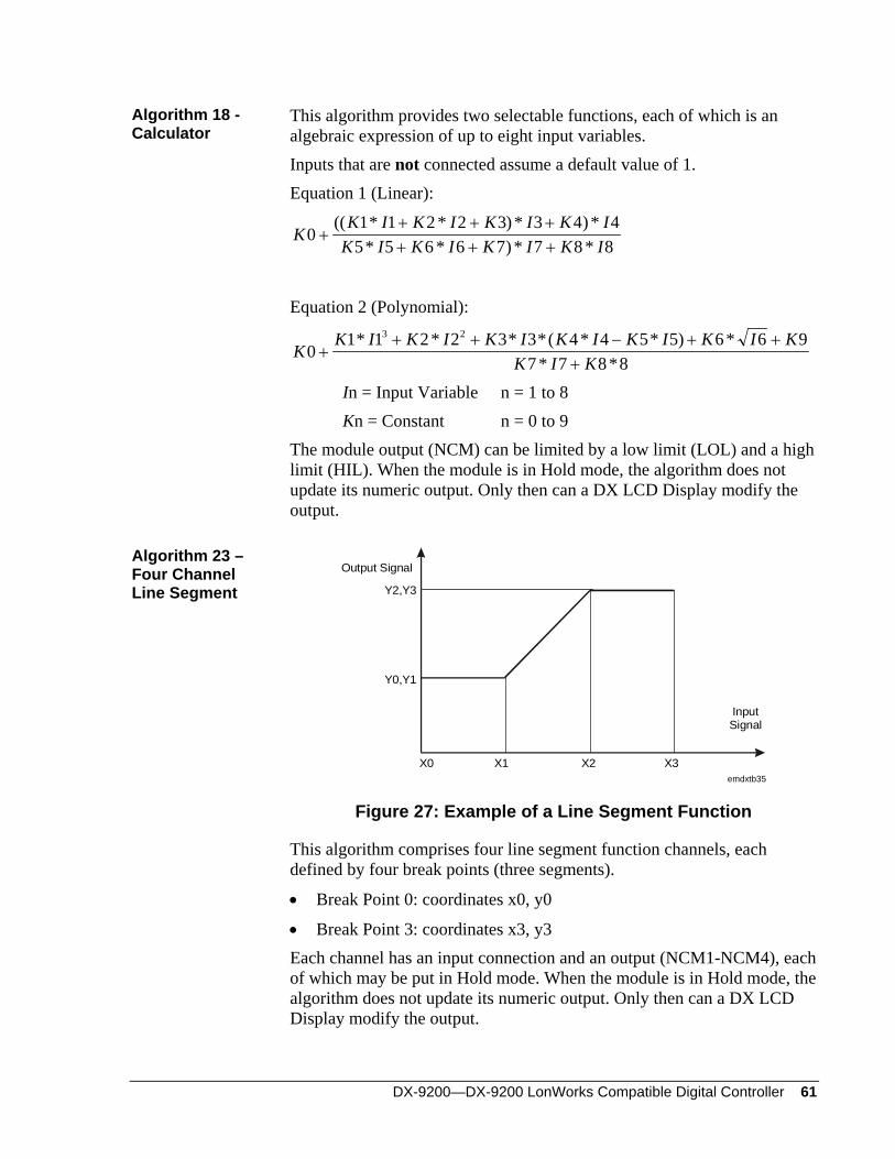
DX-9200—DX-9200 LonWorks Compatible Digital Controller 61
Algorithm 18 - Calculator
This algorithm provides two selectable functions, each of which is an algebraic expression of up to eight input variables. Inputs that are not connected assume a default value of 1. Equation 1 (Linear):
KK I K I K I K I
K I K I K I K I0
1 1 2 2 3 3 4 45 5 6 6 7 7 8 8
++ + ++ + +
(( * * ) * ) ** * ) * *
Equation 2 (Polynomial):
KK I K I K I K I K I K I K
K I K0
1 1 2 2 3 3 4 4 5 5 6 6 97 7 8 8
3 2
++ + − + +
+* * * *( * * ) *
* *
In = Input Variable n = 1 to 8 Kn = Constant n = 0 to 9 The module output (NCM) can be limited by a low limit (LOL) and a high limit (HIL). When the module is in Hold mode, the algorithm does not update its numeric output. Only then can a DX LCD Display modify the output.
Algorithm 23 – Four Channel Line Segment
X0 X1 X2 X3
InputSignal
Y0,Y1
Y2,Y3
emdxtb35
Output Signal
Figure 27: Example of a Line Segment Function
This algorithm comprises four line segment function channels, each defined by four break points (three segments).
• Break Point 0: coordinates x0, y0
• Break Point 3: coordinates x3, y3 Each channel has an input connection and an output (NCM1-NCM4), each of which may be put in Hold mode. When the module is in Hold mode, the algorithm does not update its numeric output. Only then can a DX LCD Display modify the output.
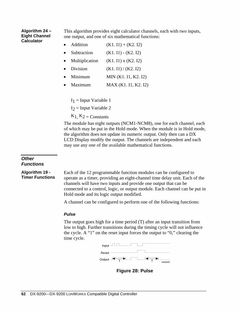
62 DX-9200—DX-9200 LONWORKS Compatible Digital Controller
Algorithm 24 – Eight Channel Calculator
This algorithm provides eight calculator channels, each with two inputs, one output, and one of six mathematical functions:
• Addition (K1. I1) + (K2. I2)
• Subtraction (K1. I1) - (K2. I2)
• Multiplication (K1. I1) x (K2. I2)
• Division (K1. I1) / (K2. I2)
• Minimum MIN (K1. I1, K2. I2)
• Maximum MAX (K1. I1, K2. I2) I1 = Input Variable 1 I2 = Input Variable 2 K1, K2 = Constants The module has eight outputs (NCM1-NCM8), one for each channel, each of which may be put in the Hold mode. When the module is in Hold mode, the algorithm does not update its numeric output. Only then can a DX LCD Display modify the output. The channels are independent and each may use any one of the available mathematical functions.
Other Functions Algorithm 19 - Timer Functions
Each of the 12 programmable function modules can be configured to operate as a timer, providing an eight-channel time delay unit. Each of the channels will have two inputs and provide one output that can be connected to a control, logic, or output module. Each channel can be put in Hold mode and its logic output modified. A channel can be configured to perform one of the following functions:
Pulse
The output goes high for a time period (T) after an input transition from low to high. Further transitions during the timing cycle will not influence the cycle. A “1” on the reset input forces the output to “0,” clearing the time cycle.
Input
Reset
Outputndxtb42T T
Figure 28: Pulse
DX-9200—DX-9200 LonWorks Compatible Digital Controller 63
Retriggerable Pulse
Similar to above with the exception that the timing period begins from the last input transition. A “1” on the reset input forces the output to “0,” clearing the time cycle.
Input
Reset
Outputemdxtb37T
Figure 29: Retriggerable Pulse
On Delay with Memory
The output goes high after a time period (T) from the input going high. If the input is high for a period less than (T), the output never goes high. A “1” on the reset input is the only way to force the output to “0,” clearing the time cycle.
Input
Reset
Outputemdxtb38
T T
Figure 30: On Delay with Memory
On Delay
The output goes high after a time period (T) from the input going high. The output goes low when the input goes low. A “1” on the reset input forces the output to “0,” clearing the time cycle.
Input
Reset
Outputndxtb43
T T T
Figure 31: On Delay
Off Delay
The output goes high when the input goes high. The output goes low after a time period (T) from the input going low.
Input
Reset
Outputndxtb46T
Figure 32: Off Delay
64 DX-9200—DX-9200 LONWORKS Compatible Digital Controller
Algorithm 20 - Totalization
Each of the 12 programmable function modules can be defined as a totalization module, capable of executing a totalization algorithm. The algorithm has eight channels available. Each channel can be configured to perform one of the following functions: Digital input event counter Analog input integrator Digital input time counter
Each channel has configurable inputs and provides one numeric output (TOT) as a result of the totalization function and a logic output (FSS) indicating that the numeric output has reached a programmed limit (FSL). Additionally, each channel has an accumulator output (ACT), which may be set to count the number of times the totalization has reached its programmed limit and to automatically reset the channel. The accumulator output has a maximum value of 9,999,999 or 32,767 (15 bits) by configuration. When the module is in Hold mode, the algorithm does not update its numeric output. Only then can a DX LCD Display modify the output.
Event Counter
This function performs the count of all transitions from “0” to “1” of a logic item connected to the input of the channel. The number of transitions is scaled to generate a numeric output. A logic item connected to a reset input sets the event counter to zero. When the output reaches a programmable full scale value, the counter full scale logic status is set and the output value remains at full scale until reset; or alternatively, the accumulator output is incremented and the channel resets to continue counting.
Integrator
This function performs the integration of the value of a numeric item connected to the input of the channel. A time constant determines the integration rate. A logic item connected to a reset input sets the integrator to zero. When the output reaches a programmable full scale value, the integrator full scale logic status is set and the output value remains at full scale until reset, or alternatively; the accumulator output is incremented and the channel resets to continue integrating.
DX-9200—DX-9200 LonWorks Compatible Digital Controller 65
Time Counter
This function increases the value of the numeric output when the connected digital input is at “1.” The output increase rate is a function of a time constant. The time counter can be set to zero by a logic item connected to a reset input. When the output reaches a programmable full scale value, the time counter full scale logic status is set and the output value remains at full scale until reset, or alternatively, the accumulator output is incremented and the channel reset to continue counting.
Algorithm 21 - Comparator
Each of the 12 programmable function modules can be defined as a module with a comparator algorithm. The algorithm has eight channels available. Each channel performs the comparison of an analog input variable with a setpoint value and, by configuration, sets a logic status when the input value exceeds or alternatively falls below the setpoint value. The numerical value of the output is equal to the deviation. The setpoint value is either a configured constant or the value of a connected numerical variable. Each channel can be individually put in Hold mode. When the module is in Hold mode, the algorithm does not update its numeric output. Only then can a DX LCD Display modify the output.
Algorithm 22 - Sequencer
Each of the 12 programmable function modules can be configured as a sequencer providing the control of one to eight logic outputs as a function of the value of an analog variable or two logic variables and the state of eight logic (disable) inputs. The sequencer interfaces with the programmable logic control module and to other programmable function modules to provide interlocking and alarm capability. Two consecutive sequencer modules can be linked together to control up to 16 outputs. When an analog variable is connected, its value determines the required output in percent of the total output. When logic variables are connected, the first variable increases the required output value and the second variable decreases the output value. The load factor for each output stage must be specified, and as a function of the total requested output the appropriate number of stages is activated. Whenever a stage is switched on or off, a delay timer is activated to prevent further stages being switched in rapid succession. The difference between the requested output and the total activated output is available as a numeric variable for connection to other modules to provide proportional corrective control if required.
66 DX-9200—DX-9200 LONWORKS Compatible Digital Controller
A set is defined to represent a physical item of equipment that requires set switching delay times to be entered independently of the stage switching delay times. For example, a set could be a refrigeration compressor that has two stages. The switching delay times for the first stage of the compressor must be longer than for the second stage because in the first stage a large motor is being switched and in the second stage only a control valve on the compressor is being switched. A special delay parameter is provided for the first set in the sequence, and a limit value for the number of switching cycles in one hour for the set can be programmed. The sequencer selects a set only if the disable logic input of the first stage of the set is not active. If the first stage is disabled when a set is running, the sequencer automatically selects another set. The sequencer can be put in Hold mode. When the module is in Hold mode, the algorithm does not update its numeric output. Only then can a DX LCD Display modify the output. Each sequencer module can be configured to operate in one of several modes:
Step mode: The output stages are controlled in sequence according to the “last on, first off” principle. For example, a three-stage sequencer controls the output stages in the following sequence:
Set Load Percent 0 33 66 100 66 33 0
1 0 1 1 1 1 1 0 2 0 0 1 1 1 0 0 3 0 0 0 1 0 0 0
Sequential: The output sets are controlled in sequence according to
the “first on, first off” principle. Stages within a set are controlled to the “last on, first off” principle. For example, a three-set sequencer controls the sets in the following sequence:
Set Load Percent 0 33 66 100 66 33 0
1 0 1 1 1 0 0 0 2 0 0 1 1 1 0 0 3 0 0 0 1 1 1 0
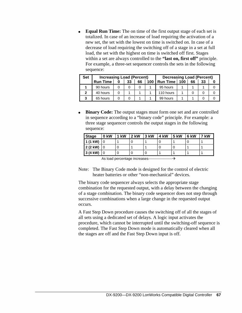
DX-9200—DX-9200 LonWorks Compatible Digital Controller 67
Equal Run Time: The on time of the first output stage of each set is totalized. In case of an increase of load requiring the activation of a new set, the set with the lowest on time is switched on. In case of a decrease of load requiring the switching off of a stage in a set at full load, the set with the highest on time is switched off first. Stages within a set are always controlled to the “last on, first off” principle. For example, a three-set sequencer controls the sets in the following sequence:
Set Increasing Load (Percent) Decreasing Load (Percent) Run Time 0 33 66 100 Run Time 100 66 33 0
1 90 hours 0 0 0 1 95 hours 1 1 1 0 2 40 hours 0 1 1 1 110 hours 1 0 0 0 3 65 hours 0 0 1 1 99 hours 1 1 0 0
Binary Code: The output stages must form one set and are controlled
in sequence according to a “binary code” principle. For example: a three stage sequencer controls the output stages in the following sequence: Stage 0 kW 1 kW 2 kW 3 kW 4 kW 5 kW 6 kW 7 kW 1 (1 kW) 0 1 0 1 0 1 0 1 2 (2 kW) 0 0 1 1 0 0 1 1 3 (4 kW) 0 0 0 0 1 1 1 1
As load percentage increases-------------------- Note: The Binary Code mode is designed for the control of electric
heater batteries or other “non-mechanical” devices. The binary code sequencer always selects the appropriate stage combination for the requested output, with a delay between the changing of a stage combination. The binary code sequencer does not step through successive combinations when a large change in the requested output occurs. A Fast Step Down procedure causes the switching off of all the stages of all sets using a dedicated set of delays. A logic input activates the procedure, which cannot be interrupted until the switching-off sequence is completed. The Fast Step Down mode is automatically cleared when all the stages are off and the Fast Step Down input is off.
68 DX-9200—DX-9200 LONWORKS Compatible Digital Controller
Programmable Logic Control
The DX-9200 operating system provides a software-implemented programmable logic controller (PLC), which supports most of the functions available in dedicated PLCs. Every second the PLC module executes a user-defined program, which references a memory area containing an image of the hardware digital inputs/outputs, logic variables from programmable function modules, logic result status variables, and digital constants that are required by the PLC program. Variables in the memory area are frozen before the execution of the program in the PLC module, and the resulting changes in the logic variables are transferred out of the memory area to the appropriate hardware or function modules at the end of the module execution.
emdxtb41
User-definedProgram
Hardware Inputs
Hardware Outputs
Logic Variables
PLC Memory Area
PLC Module
Figure 33: Programmable Logic Control
PLC User-Defined Program
A user-defined program is a sequence of instruction blocks and sub blocks that contain logic instructions. Each instruction block has a result status that is initialized by the first instruction of the block and transferred to the memory area by the final instruction of the block. When executing sub blocks, the PLC program creates a partial result status that is logically combined with the result status at the end of the sub block. In the GX-9100 Graphic Configuration Software, the instructions are laid out in eight pages of ladder diagrams, each containing eight lines of up to eight instructions, graphically depicted as shown below.
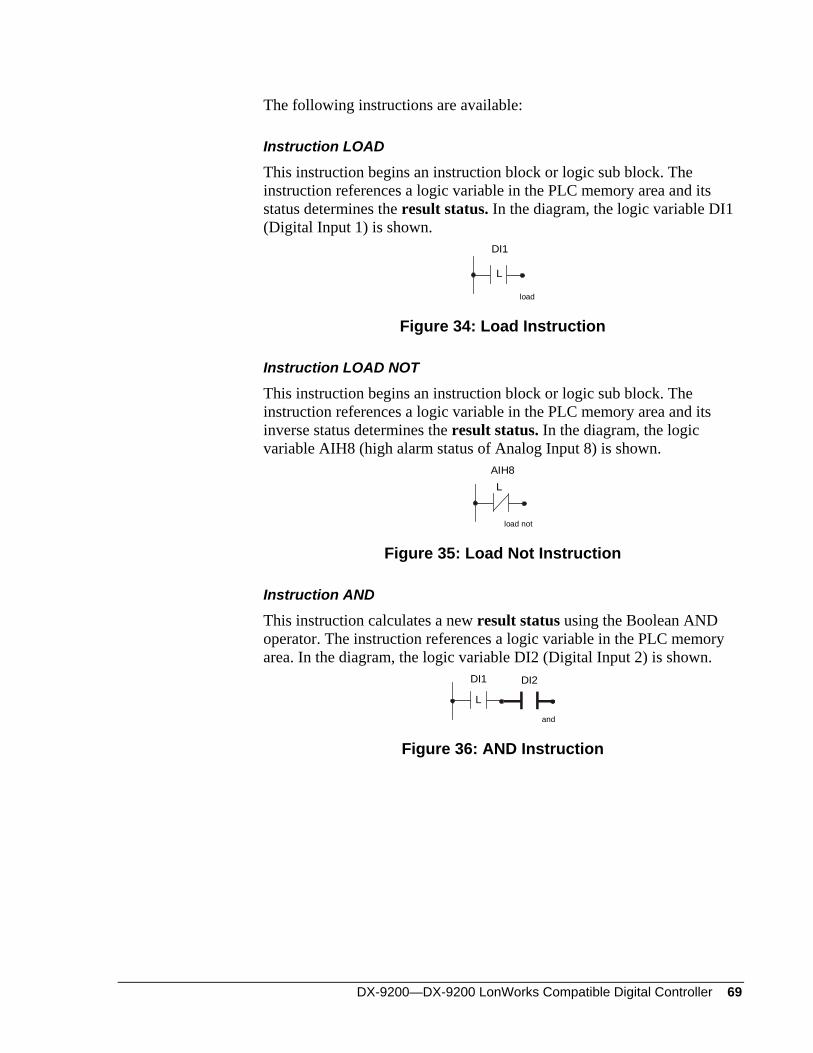
DX-9200—DX-9200 LonWorks Compatible Digital Controller 69
The following instructions are available:
Instruction LOAD
This instruction begins an instruction block or logic sub block. The instruction references a logic variable in the PLC memory area and its status determines the result status. In the diagram, the logic variable DI1 (Digital Input 1) is shown.
L
DI1
load
Figure 34: Load Instruction
Instruction LOAD NOT
This instruction begins an instruction block or logic sub block. The instruction references a logic variable in the PLC memory area and its inverse status determines the result status. In the diagram, the logic variable AIH8 (high alarm status of Analog Input 8) is shown.
LAIH8
load not
Figure 35: Load Not Instruction
Instruction AND
This instruction calculates a new result status using the Boolean AND operator. The instruction references a logic variable in the PLC memory area. In the diagram, the logic variable DI2 (Digital Input 2) is shown.
L
DI1
and
DI2
Figure 36: AND Instruction
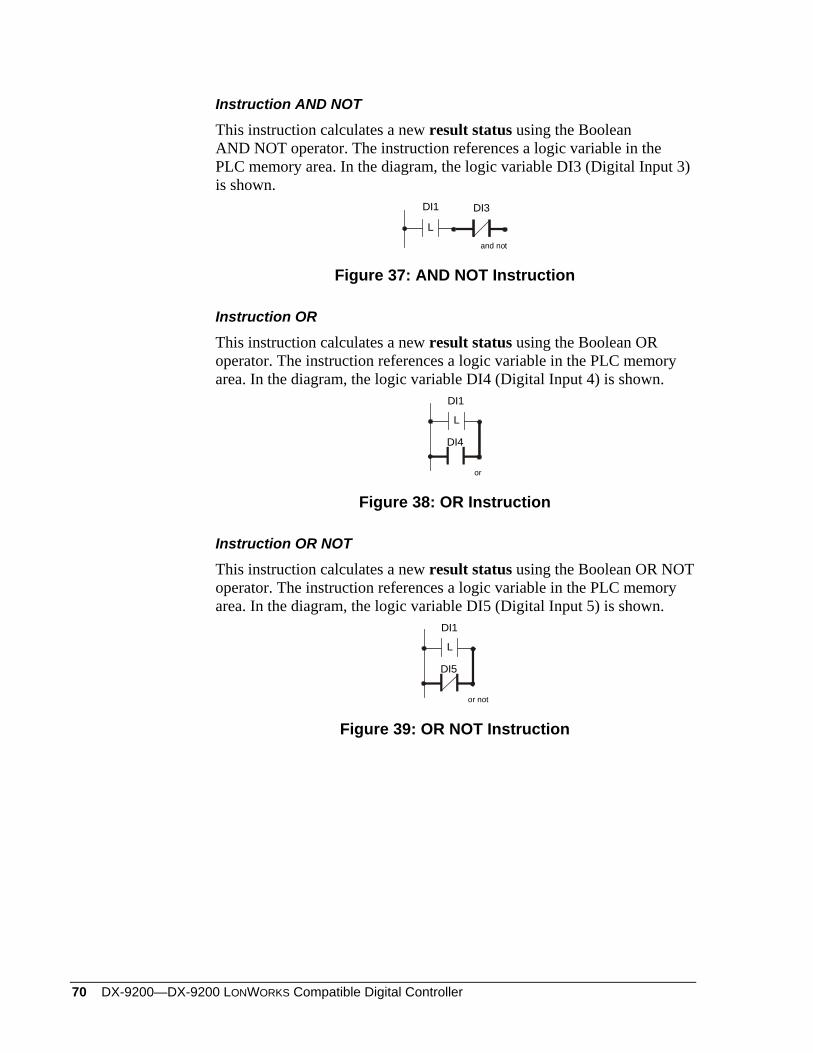
70 DX-9200—DX-9200 LONWORKS Compatible Digital Controller
Instruction AND NOT
This instruction calculates a new result status using the Boolean AND NOT operator. The instruction references a logic variable in the PLC memory area. In the diagram, the logic variable DI3 (Digital Input 3) is shown.
L
DI1
and not
DI3
Figure 37: AND NOT Instruction
Instruction OR
This instruction calculates a new result status using the Boolean OR operator. The instruction references a logic variable in the PLC memory area. In the diagram, the logic variable DI4 (Digital Input 4) is shown.
L
DI1
or
DI4
Figure 38: OR Instruction
Instruction OR NOT
This instruction calculates a new result status using the Boolean OR NOT operator. The instruction references a logic variable in the PLC memory area. In the diagram, the logic variable DI5 (Digital Input 5) is shown.
L
DI1
or not
DI5
Figure 39: OR NOT Instruction
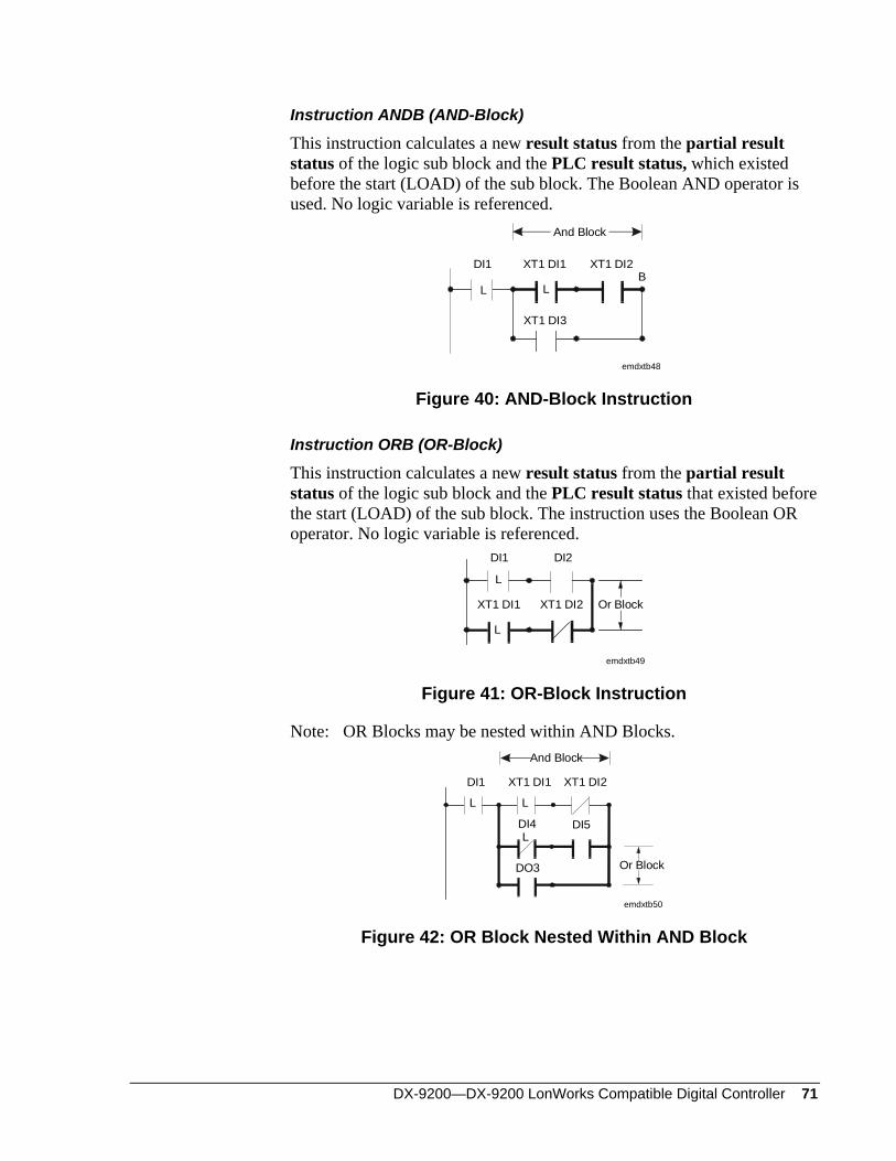
DX-9200—DX-9200 LonWorks Compatible Digital Controller 71
Instruction ANDB (AND-Block)
This instruction calculates a new result status from the partial result status of the logic sub block and the PLC result status, which existed before the start (LOAD) of the sub block. The Boolean AND operator is used. No logic variable is referenced.
L LB
And Block
DI1 XT1 DI1 XT1 DI2
XT1 DI3
emdxtb48
Figure 40: AND-Block Instruction
Instruction ORB (OR-Block)
This instruction calculates a new result status from the partial result status of the logic sub block and the PLC result status that existed before the start (LOAD) of the sub block. The instruction uses the Boolean OR operator. No logic variable is referenced.
DI1
L
L
DI2
XT1 DI1 XT1 DI2
emdxtb49
Or Block
Figure 41: OR-Block Instruction
Note: OR Blocks may be nested within AND Blocks.
L L
XT1 DI1 XT1 DI2DI1
DI4 DI5
DO3
L
emdxtb50
Or Block
And Block
Figure 42: OR Block Nested Within AND Block
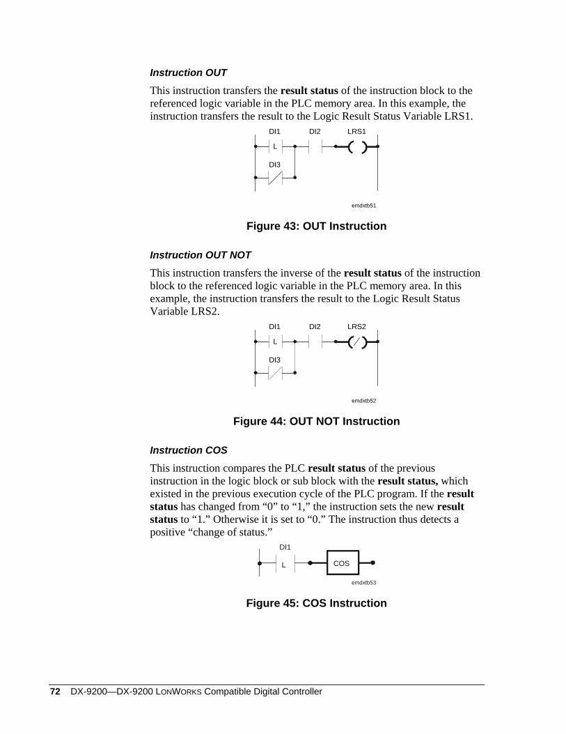
72 DX-9200—DX-9200 LONWORKS Compatible Digital Controller
Instruction OUT
This instruction transfers the result status of the instruction block to the referenced logic variable in the PLC memory area. In this example, the instruction transfers the result to the Logic Result Status Variable LRS1.
DI1 DI2
L
LRS1
DI3
emdxtb51
Figure 43: OUT Instruction
Instruction OUT NOT
This instruction transfers the inverse of the result status of the instruction block to the referenced logic variable in the PLC memory area. In this example, the instruction transfers the result to the Logic Result Status Variable LRS2.
DI1 DI2
L
LRS2
DI3
emdxtb52
Figure 44: OUT NOT Instruction
Instruction COS
This instruction compares the PLC result status of the previous instruction in the logic block or sub block with the result status, which existed in the previous execution cycle of the PLC program. If the result status has changed from “0” to “1,” the instruction sets the new result status to “1.” Otherwise it is set to “0.” The instruction thus detects a positive “change of status.”
COSL
DI1
emdxtb53
Figure 45: COS Instruction
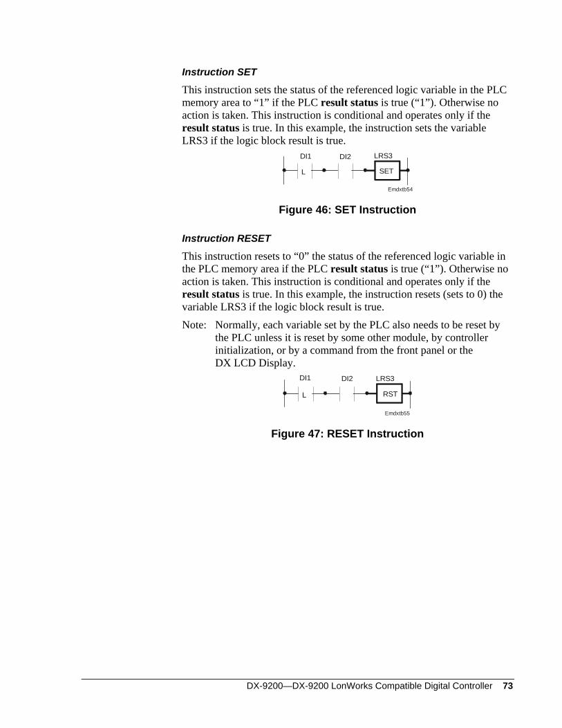
DX-9200—DX-9200 LonWorks Compatible Digital Controller 73
Instruction SET
This instruction sets the status of the referenced logic variable in the PLC memory area to “1” if the PLC result status is true (“1”). Otherwise no action is taken. This instruction is conditional and operates only if the result status is true. In this example, the instruction sets the variable LRS3 if the logic block result is true.
SETL
DI1 DI2 LRS3
Emdxtb54
Figure 46: SET Instruction
Instruction RESET
This instruction resets to “0” the status of the referenced logic variable in the PLC memory area if the PLC result status is true (“1”). Otherwise no action is taken. This instruction is conditional and operates only if the result status is true. In this example, the instruction resets (sets to 0) the variable LRS3 if the logic block result is true. Note: Normally, each variable set by the PLC also needs to be reset by
the PLC unless it is reset by some other module, by controller initialization, or by a command from the front panel or the DX LCD Display.
RSTL
DI1 DI2 LRS3
Emdxtb55
Figure 47: RESET Instruction
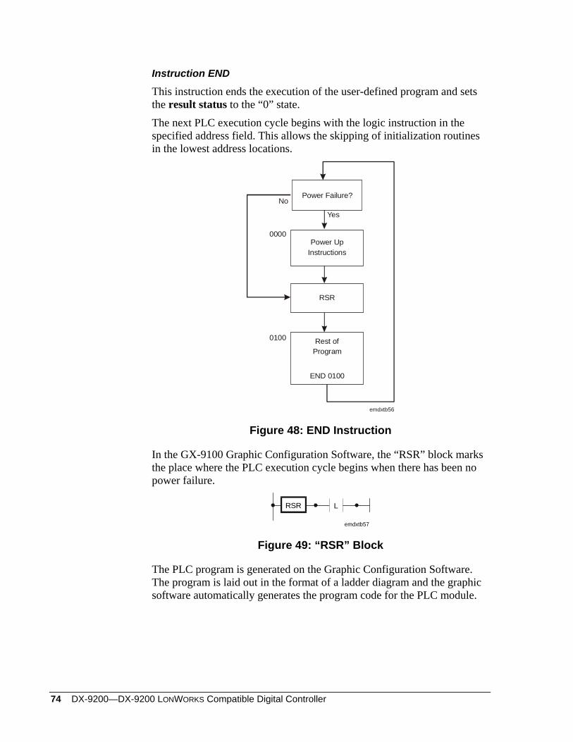
74 DX-9200—DX-9200 LONWORKS Compatible Digital Controller
Instruction END
This instruction ends the execution of the user-defined program and sets the result status to the “0” state. The next PLC execution cycle begins with the logic instruction in the specified address field. This allows the skipping of initialization routines in the lowest address locations.
Rest ofProgram
0100
0000
END 0100
RSR
emdxtb56
Power Failure?
Power UpInstructions
Yes
No
Figure 48: END Instruction
In the GX-9100 Graphic Configuration Software, the “RSR” block marks the place where the PLC execution cycle begins when there has been no power failure.
RSR L
emdxtb57
Figure 49: “RSR” Block
The PLC program is generated on the Graphic Configuration Software. The program is laid out in the format of a ladder diagram and the graphic software automatically generates the program code for the PLC module.
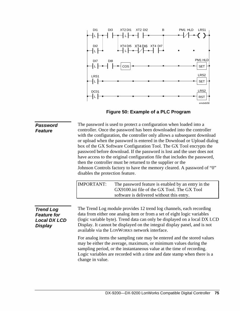
DX-9200—DX-9200 LonWorks Compatible Digital Controller 75
DI1
DI2
DI7
LRS1
DC01
LRS2
LRS2
PM1 HLDDI8
DI3 XT2
XT4
XT2
XT4
B PM1 HLD LRS1DI2
XT4 DI6 DI7
DI1
DI5
emdxtb58
L
L
L
L
L
L
L
COS SET
SET
RST
Figure 50: Example of a PLC Program
The password is used to protect a configuration when loaded into a controller. Once the password has been downloaded into the controller with the configuration, the controller only allows a subsequent download or upload when the password is entered in the Download or Upload dialog box of the GX Software Configuration Tool. The GX Tool encrypts the password before download. If the password is lost and the user does not have access to the original configuration file that includes the password, then the controller must be returned to the supplier or the Johnson Controls factory to have the memory cleared. A password of “0” disables the protection feature.
Password Feature
IMPORTANT: The password feature is enabled by an entry in the GX9100.ini file of the GX Tool. The GX Tool software is delivered without this entry.
The Trend Log module provides 12 trend log channels, each recording data from either one analog item or from a set of eight logic variables (logic variable byte). Trend data can only be displayed on a local DX LCD Display. It cannot be displayed on the integral display panel, and is not available via the LONWORKS network interface.
Trend Log Feature for Local DX LCD Display
For analog items the sampling rate may be entered and the stored values may be either the average, maximum, or minimum values during the sampling period, or the instantaneous value at the time of recording. Logic variables are recorded with a time and date stamp when there is a change in value.

76 DX-9200—DX-9200 LONWORKS Compatible Digital Controller
DX-9200—DX-9200 LonWorks Compatible Digital Controller 77
Software Configuration
The section Software Configuration and Appendices A, B, C, D, and E of the DX-9100 Configuration Guide (LIT-6364030) generally apply to the DX-9200 when referring to a Version 3 controller. The exceptions are explained in detail in this chapter.
General
Note: To configure the DX-9200 controller via the GX Tool, under the Controller Menu, select DX Version 3.3, 3.4.
DX-9200 Global Data Set “Initialize on Power Up” Flag
Counter Type Flag
See Supervisory Mode Control Settings (General Module) in this section.
The controller has up to 16 network analog input modules, each of which holds a numerical value from its associated LONMARK network variable. These inputs can be used in the configuration in the same way as physical analog inputs. The source of the analog data can be a LONWORKS compatible supervisory system such as the Metasys NCM or another device on the LONWORKS network. For details of the LONMARK network variables in each DX-9200 model, refer to Network Variable Internal Mapping Tables later in this document.
Network Analog Input Configuration
User Tag Name For each network analog input module, one must define the User Tag Name and Description.
Via GX Tool
Select PM from the toolbar, then Network Analog Input, and place the NAIn on the screen. Select NAIn and Data. Enter the User Name and Description in the Data Window.
Via SX Tool
Set Item NAIN (RI.04) to “1” if any NAIs are used in the configuration. The GX Tool automatically sets this item when the NAI is created.
78 DX-9200—DX-9200 LONWORKS Compatible Digital Controller
NAI Notes 1. On the SX Tool, the numeric value of the network analog inputs can be read at Items NAIn (RI.01 to RI.16) under “NETWORK” and “INPUT MODULES.”
2. On the SX Tool, the Reliability Status of each analog input module can be seen on Bits X1 to X16 at Item NAISTA (RI.17). These status indications can be used for backup control strategies in the case of a transmission failure by using the corresponding logic variables (NAIU1 to NAIU16) in the PLC. The Reliability Status is set to “1” (Unreliable) when the DX controller does not receive a new value over the network within the period set in the network variable Receive Heartbeat (default is 200 seconds), or when the value is equal to the invalid value as defined in the Standard Network Variable Type (SNVT) definition. (Refer to Network Configuration and Node Control Network Variables later in this document.)
3. The Items NAInDIM (RI.18 to RI.33) are not used in the DX-9200.
GX Labels Source Points (Outputs)
NAIn The current value of the Network Analog Input NAIUn A “1” when the analog input module is unreliable
Destination Points (Inputs)
None
The controller has up to 8 network digital input modules, each with 16 digital input logic values that hold an enumerated value or a set of binary values from the associated LONMARK network variables. These digital inputs are used in the configuration in the same way as physical digital inputs. The source of the digital data can be a LONWORKS compatible supervisory system such as the Metasys NCM or another device on the LONWORKS network. For details of the LONMARK network variables in each DX-9200 model, refer to Network Variable Internal Mapping Tables later in this document.
Network Digital Input Configuration
For each network analog input module, one must define the User Tag Name and Description.
User Tag Name Via the GX Tool
Select PM in the toolbar, then Network Digital Input, and place the NDIn on the screen. Select NDIn and Data. Enter the User Name and Description in the Data Window.
Via SX Tool
Set Item NDIN (RI.03) to “1” if any NDIs are used in the configuration. The GX Tool automatically sets this item when the NDI is created.
DX-9200—DX-9200 LonWorks Compatible Digital Controller 79
NDI Notes 1. On the SX Tool, the status values of the 16 digital inputs in each of the eight network digital input modules can be read at Bits X1 to X16 in Items NDIn (RI.01 to RI.8) under “NETWORK”, “INPUT MODULES,” and “1” (NETWORK DI MOD). The status values are used in the configuration by connecting the corresponding logic variables NDIn-1 to NDIn-16.
2. On the SX Tool the Reliability Status of each digital input module can be seen on Bits X1 to X8 at Item NDISTA (RI.9). These status indications can be used for backup control strategies in the case of a transmission failure by using the corresponding logic variables (NDIU1 to NDIU8) in the PLC. The Reliability Status is set to “1” (Unreliable) when the DX controller does not receive a new value over the network within the period set in the network variable Receive Heartbeat (default is 200 seconds), or when the value is equal to the invalid value as defined in the Standard Network Variable Type (SNVT) definition. (Refer to Network Configuration and Node Control Network Variables later in this document.) The Reliability Status of a network digital input module that is associated with more than one LONMARK network variable is only set when none of the values are updated. For network variables of type SNVT_switch, use the reliability status of the associated network analog input module, if mapped.
3. The Reliability Status of network digital input bits mapped to the state element of a network variable of type SNVT_switch can be seen in the most significant bits of the digital input module. The Reliability Status of the state in BIT X (X = 1-8) is given in Bit X+8 (X+8 = 9-16). The Reliability Status bit is set when the state element has an invalid value as defined for SNVT_switch (normally FF(Hex)), and after a power failure or reset until a new reliable state has been received. It is not set when the heartbeat time expires. For network variables of type SNVT_switch, use the Reliability Status of the associated network analog input module, if mapped, to detect an unreliable value because of the timeout of the heartbeat function.
4. The Items NDInTYP (RI.10 to RI.17) are not used in the DX-9200.
GX Labels Source Points (Outputs)
NDIn-m The current value of the Network Digital Input NDIUn A “1” when the digital input module is unreliable
Destination Points (Inputs)
None
80 DX-9200—DX-9200 LONWORKS Compatible Digital Controller
Network Analog Output Configuration
The DX-9200 controller uses up to 16 network analog outputs, depending on the controller model, each of which holds a numerical value for transfer to its associated LONMARK network variable. These network outputs receive their values via a connection to a numeric Item in the controller. The analog data in the LONMARK network variable can then be read by a LONWORKS compatible supervisory system such as the Metasys NCM, or be transmitted to another device on the LONWORKS network. For details of the LONMARK network variables in each DX-9200 model, refer to Network Variable Internal Mapping Tables later in this document. For each network analog output module, one must define:
• User Tag Name and Description
• the source of the output module
User Tag Name Via the GX Tool
Select PM, then Network Analog Output, and place the NAOn on the screen. Select NAOn and Data. Enter the User Name and Description in the Data Window.
Via the SX Tool
Set Item NAOn (RI.02) to the number of NAO modules that are used in the configuration. The GX Tool automatically sets this item when the NAO is created.
NAO Source Via GX Tool
Expand NAOn to show the input NAOnAO@. Expand the source module with the desired output numeric Item and make the connection. The connection source may be seen in the NAO Data Window in the field “Source Point.”
Via SX Tool
Connections are defined in Items NAOn@ (RI.20) under “NETWORK” (Key 8), “OUTPUT MODULES,” and “2” (NETWORK AO MODn) (n = 1-16). Enter a numeric Item address.
NAO Notes 1. On the SX Tool the numeric value of the network analog outputs can be read at Items NAOnOUT (RI.01) under “NETWORK,” “OUTPUT MODULES,” and “2” (NETWORK AO MODn) (n = 1-16).
2. The destination Items NAOn>m and the Analog Output Failure Status Item NAOnSTA are not used in the DX-9200.
3. The Analog Output Units Item NAOnDIM (RI.03) is not used in the DX-9200.
DX-9200—DX-9200 LonWorks Compatible Digital Controller 81
GX Labels Source Points (Outputs)
None
Destination Points (Inputs)
NAOn@ The numeric connection to control a Network Analog Output.
The controller has up to 8 network digital output modules, each with 16 digital output logic values for transfer either individually or as an enumerated set to the associated LONMARK network variables. These network outputs receive their values via a connection to a logic variable in the controller. The logic data in the LONMARK network variable can then be read by a LONWORKS compatible supervisory system such as the Metasys NCM or be transmitted to another device on the LONWORKS network. For details of the LONMARK network variables in each DX-9200 model, refer to Network Variable Internal Mapping Tables later in this document.
Network Digital Output Configuration
For each network digital output module, one must define:
• User Tag Name and Description
• the source of the 16 digital status values in the output module
User Tag Name Via the GX Tool
Select PM, then Network Digital Output, and place NDOn on the screen. Select NDOn and Data. Enter the User Name and Description in the Data Window.
Via SX Tool
Set Item NDOn (RI.01) to the number of NDO modules that are used in the configuration. The GX Tool automatically sets this item when the NDO is created.
NDO Sources Via GX Tool
Expand NDOn to show the inputs NDOn-1@ to NDOn-16@. Expand the source module with the desired output logic variable and make the connection. The connection sources may be seen in the NDO Data Window in the fields “Source Bit 1” to “Source Bit 16.”
Via SX Tool
Connections are defined in Items NDOn-1@ to NDOn-16@ (RI.20 to RI.35) under “NETWORK” (Key 8), “OUTPUT MODULES,” and “1” (NETWORK DO MODn) (n = 1-8). Enter a logic variable index byte and bit number.
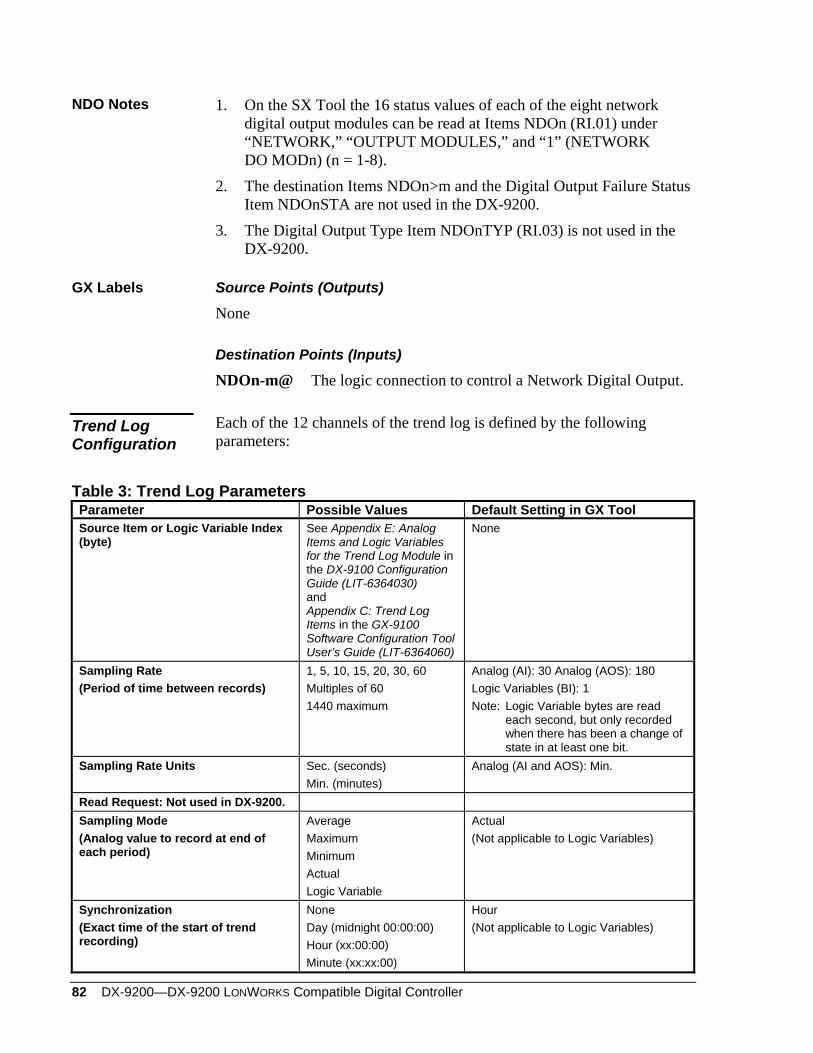
82 DX-9200—DX-9200 LONWORKS Compatible Digital Controller
NDO Notes 1. On the SX Tool the 16 status values of each of the eight network digital output modules can be read at Items NDOn (RI.01) under “NETWORK,” “OUTPUT MODULES,” and “1” (NETWORK DO MODn) (n = 1-8).
2. The destination Items NDOn>m and the Digital Output Failure Status Item NDOnSTA are not used in the DX-9200.
3. The Digital Output Type Item NDOnTYP (RI.03) is not used in the DX-9200.
GX Labels Source Points (Outputs)
None
Destination Points (Inputs)
NDOn-m@ The logic connection to control a Network Digital Output.
Each of the 12 channels of the trend log is defined by the following parameters:
Trend Log Configuration
Table 3: Trend Log Parameters Parameter Possible Values Default Setting in GX Tool Source Item or Logic Variable Index (byte)
See Appendix E: Analog Items and Logic Variables for the Trend Log Module in the DX-9100 Configuration Guide (LIT-6364030) and Appendix C: Trend Log Items in the GX-9100 Software Configuration Tool User’s Guide (LIT-6364060)
None
Sampling Rate (Period of time between records)
1, 5, 10, 15, 20, 30, 60 Multiples of 60 1440 maximum
Analog (AI): 30 Analog (AOS): 180 Logic Variables (BI): 1 Note: Logic Variable bytes are read
each second, but only recorded when there has been a change of state in at least one bit.
Sampling Rate Units Sec. (seconds) Min. (minutes)
Analog (AI and AOS): Min.
Read Request: Not used in DX-9200. Sampling Mode (Analog value to record at end of each period)
Average Maximum Minimum Actual Logic Variable
Actual (Not applicable to Logic Variables)
Synchronization (Exact time of the start of trend recording)
None Day (midnight 00:00:00) Hour (xx:00:00) Minute (xx:xx:00)
Hour (Not applicable to Logic Variables)
DX-9200—DX-9200 LonWorks Compatible Digital Controller 83
Via the GX Tool
Click on PM in the Tool Bar, then select Trend and position the module on the screen. Double click on the TREND LOG module block. The Trend Log definition table with 12 rows, one for each channel, appears. Highlight a channel, then select Data. In the dialog box, do not check the Metasys Point History box. The Metasys Point History feature is not supported by the DX-9200 as this controller cannot be monitored remotely with an NDM dialer. Enter the desired Tag Name of the item or logic variable set to be recorded. One or two data windows appear when a valid tag name has been entered, depending on whether an analog item or logic variable set was selected. Refer to Appendix E: Analog Items and Logic Variables for the Trend Log Module in the DX-9100 Configuration Guide (LIT-6364030) and Appendix C: Trend Log Items in the GX-9100 Software Configuration Tool User’s Guide (LIT-6364060) for a list of the tag names available for Trend Log. Enter the desired values in the data fields. Note: When selecting a logic variable, choose the logic variable set that
contains the required variable. All variables in the set will then be available for the DX LCD Display. Since a logic variable set is recorded when any one of its variables changes state, you should assign LRS logic variables sets (bytes) to trend log and connect the source variables (the ones you wish to trend) to the individual LRS logic variables in a PLC module to form a “trend log logic variable group.”
Via the SX Tool
Trend log cannot be configured with the SX Tool.
Supervisory Mode Control Settings (General Module)
Access to the Controller
Access to the LONWORKS compatible DX-9200 controller for supervisory purposes over the LONWORKS network is only possible through the LONMARK network variables. As the Supervisory System Active bit cannot be set through a LONMARK network variable, the controller effectively runs in stand-alone mode at all times. Therefore, the DX-9200 controller does not use to any of the supervisory mode control settings that require the Supervisory System Active bit to be set. It does, however, use control settings associated with the Hold mode, which is set from the integral front panel or a DX LCD Display.
84 DX-9200—DX-9200 LONWORKS Compatible Digital Controller
The following supervisory control modes cannot be used in the DX-9200 controller: For PID and On/Off control modules:
• Shutoff mode
• Startup mode
• Computer mode
For digital outputs (triacs):
• Enable supervisory control
• Set outputs to On or Off
In the DX-9200 the supervisory Startup mode cannot be used in PID and On/Off control modules.
Startup Mode
Via the GX Tool
In the Data Window for a PID or On/Off programmable module, leave the “Ena.Startup Mode” field at 0.
Via the SX Tool
Under “Program Modules” leave the PM Item PMnOPT (RI.01) Bit X3 (STAE) at 0.
In the DX-9200 the supervisory Shutoff mode cannot be used in PID and On/Off control modules.
Shutoff Mode
Via the GX Tool
In the Data Window for a PID or On/Off programmable module, leave the Ena.Shutoff Mode field at 0.
Via the SX Tool
Under “Program Modules” leave the PM Item PMnOPT (RI.01) Bit X1 (SOFE) at 0.
Hold Mode In the DX-9200 the Hold mode cannot be set directly over the LONWORKS network. The Hold mode is set when an override is entered on the integral front panel (using the A/M key) or the DX LCD Display. In Hold mode, the value of the associated item is not updated by its module input source or algorithm, and can only be changed from the front panel or DX LCD Display. Refer also to Power Up Conditions, Hold Mode below.
DX-9200—DX-9200 LonWorks Compatible Digital Controller 85
Via the GX Tool
Modules cannot be put in Hold mode directly by the GX Tool. Hold modes may, however, be set and reset by the PLC, or on power-up. Refer to Power Up Conditions, Hold mode below, and to Programmable Logic Controller Configuration, PLC User-Defined Program in the DX-9100 Configuration Guide (LIT-6364030).
Via the SX Tool
For each programmable function module, the control and status of Hold modes is available under “Program Modules” at PM Item PMnHDC (RI.70) Bits X1-X8. For time schedule modules, the control of Hold mode is available under “Time Sched” TSnSTA (RI.06) Bit X1 (TSnHLD). For analog output modules, the control of Hold mode is available under “Output Modules” at Item AOC (RI.07) Bit X1 (OUH). For digital output modules, the control of Hold mode is available under “Output Modules” at Item DOC (RI.12) Bit X1 (OUH). For extension module outputs, the control of Hold mode is available under “XT Modules” at Item XTnHDC (RI.69) Bits X1-X8 (OUH1-8).
In the DX-9200, the supervisory Computer mode cannot be used in PID and On/Off control modules.
Computer Mode
Controlling Digital Outputs
In the DX-9200, the digital outputs (triacs) cannot be set directly over the LONWORKS network. For testing purposes, the digital outputs can be set by the SX Tool.
Via the SX Tool
First, the SX may enable control of the six digital (triac) outputs of the controller by setting bits X9 to X14 of Item SUP (RI.01) under “General Module.” Control the triacs On or Off by setting Bits X1 to X6 of Item SUP (RI.01) (under “General Modules”) to “1” or “0,” respectively. The status of the triacs can be seen under “General Modules” at Item TOS (RI.05) X1=D03...X6=D08.
Maintenance Control
This function is not available in the DX-9200 controller.
86 DX-9200—DX-9200 LONWORKS Compatible Digital Controller
Counter Size As counter data cannot be connected to network outputs, there is no reason to change the size of the counter data in the DX-9200 controller from the 4-byte setting required to display up to 9,999,999 on the front panel or DX LCD Display. If the LONWORKS interface of the DX-9200 includes a network variable that supports counter data, it must be connected to the output of a Totalization module and be limited to 2047 counts.
Via GX Tool Select Edit-Global Data. Under “Counter Type” and ensure that the 4-byte field is marked.
Via the SX Tool Under “General Module”, Item DXS1 (RI.32), set Bit X4 to 1 (4-byte counters).
Serial Link Monitoring
The serial link (N2 Bus), the SSA (Supervisory System Active) bit, and SLA (Serial Link Active) bit are not used in the DX-9200 controller.
Supervisory System Monitoring
If it is desired to monitor the activity of a supervisory system such as the Metasys NCM, then the heartbeat feature of LONWORKS can be used. Select an input network variable that supports heartbeat and program the supervisory system to regularly send a value to this network variable within a time cycle that is less than the Receive Heartbeat Time set in the network variable nciRcvHrtbt (refer to the section Network Configuration and Node Control Network Variables later in this document). The reliability status of the selected network variable indicates if the supervisory system is active. Refer to the section Network Analog Input Configuration and Network Digital Input Configuration earlier in this document for details about reliability status. The reliability status can be used as a data source to initiate alternative control action within the software configuration of the controller.
The DX-9200 controller indicates when the internal lithium battery has discharged to approximately 20% of its initial capacity (BATLOW).
Controller Diagnostics
Via GX Tool In the PLC the BATLOW variable is listed under DIAGNOSTIC. The variables SLF, HTRR, and MNT are not used in the DX-9200.
Via the SX Tool The logic variable may be seen in the General Module under Item DIAG (RI.03). X2 = 0 BATLOW Lithium battery OK X2 = 1 BATLOW Lithium battery low charge
DX-9200—DX-9200 LonWorks Compatible Digital Controller 87
Power Up Conditions
Hold Mode After a power failure the following modules may be set to Hold, reset to “Auto mode”(set Hold mode to 0), or the mode before the power failure occurred:
Analog Output Module Hold Logic Output Module Hold Programmable Function Module Hold Time Schedule Module Hold Optimal Start Module Hold
These commands take priority over the override mode command initialization described in the next section, Supervisory Mode Commands Initialization.
Supervisory Mode Commands Initialization
The initialization of supervisory mode commands after a power failure of the DX-9200 controller applies only to the Hold modes (set by override commands from the front panel or a DX LCD Display).
Via the GX Tool
Select Edit>Global Data. Under “Init. On PowerUp,” select Maintained or Cancelled.
• Maintained = retain Hold modes
• Cancelled = release Hold modes
Via the SX Tool
Under “General Module” DX-9200 Type Settings, set Bit X8 of Item DXS1 (RI.32) as follows: X8 = 0 No initialization on power up X8 = 1 Initialize on power up
Programmable Logic Controller (PLC)
At power up, the PLC always runs from the first instruction in the program. Special power up routines should therefore be configured at the beginning of the program. These routines are not executed in subsequent program cycles when the address of the first “non-power up” instruction is entered in the END instruction. In the GX Tool, the location of the first “non-power up” instruction is marked by the “RSR” element in the ladder diagram.
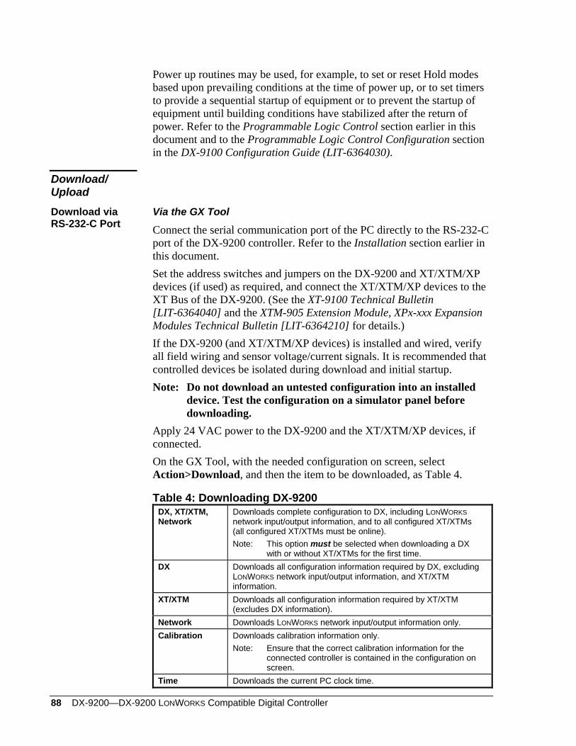
88 DX-9200—DX-9200 LONWORKS Compatible Digital Controller
Power up routines may be used, for example, to set or reset Hold modes based upon prevailing conditions at the time of power up, or to set timers to provide a sequential startup of equipment or to prevent the startup of equipment until building conditions have stabilized after the return of power. Refer to the Programmable Logic Control section earlier in this document and to the Programmable Logic Control Configuration section in the DX-9100 Configuration Guide (LIT-6364030).
Download/ Upload Download via RS-232-C Port
Via the GX Tool
Connect the serial communication port of the PC directly to the RS-232-C port of the DX-9200 controller. Refer to the Installation section earlier in this document. Set the address switches and jumpers on the DX-9200 and XT/XTM/XP devices (if used) as required, and connect the XT/XTM/XP devices to the XT Bus of the DX-9200. (See the XT-9100 Technical Bulletin [LIT-6364040] and the XTM-905 Extension Module, XPx-xxx Expansion Modules Technical Bulletin [LIT-6364210] for details.) If the DX-9200 (and XT/XTM/XP devices) is installed and wired, verify all field wiring and sensor voltage/current signals. It is recommended that controlled devices be isolated during download and initial startup. Note: Do not download an untested configuration into an installed
device. Test the configuration on a simulator panel before downloading.
Apply 24 VAC power to the DX-9200 and the XT/XTM/XP devices, if connected. On the GX Tool, with the needed configuration on screen, select Action>Download, and then the item to be downloaded, as Table 4.
Table 4: Downloading DX-9200 DX, XT/XTM, Network
Downloads complete configuration to DX, including LONWORKS network input/output information, and to all configured XT/XTMs (all configured XT/XTMs must be online). Note: This option must be selected when downloading a DX
with or without XT/XTMs for the first time. DX Downloads all configuration information required by DX, excluding
LONWORKS network input/output information, and XT/XTM information.
XT/XTM Downloads all configuration information required by XT/XTM (excludes DX information).
Network Downloads LONWORKS network input/output information only. Calibration Downloads calibration information only.
Note: Ensure that the correct calibration information for the connected controller is contained in the configuration on screen.
Time Downloads the current PC clock time.
DX-9200—DX-9200 LonWorks Compatible Digital Controller 89
Enter the DX-9200 address (0-255) in the “Address” field. Under “Port,” select the PC serial communication port (Com 1 or 2). Enter the password code if the configuration in the controller has been protected by a password. Click on OK to confirm entries. Checks are made before the data is downloaded to the controller. The user may abort the download process by selecting CANCEL.
Upload via the RS-232-C Port
Via the GX Tool
Only complete DX-9200/XT-9100/XTM-905 configurations should be uploaded from the DX-9200. Select Action>Upload, and then the Item to be uploaded (for example, DX and XT/XTM). Enter the DX-9200 address (0-255) in the “Address” field. Under “Port,” select the PC serial communication port (Com 1 or 2). Enter the password code if the configuration in the controller has been protected by a password. Click on OK to confirm entries. If the configuration in the controller matches that on the GX Tool screen, the parameters are uploaded from the controller and replace those in the GX Tool configuration. If the configuration does not match the GX Tool screen, the user is prompted to save the displayed GX Tool configuration and save the uploaded configuration to another file.
Via the SX Tool
The configuration entered into the DX-9200 controller may be stored in the service module as an ALGORITHM for transfer to another controller when not protected by a password. Refer to the SX-9120 Service Module User’s Guide (LIT-6364070) for further details.
Each DX-9200 controller has a set of unique calibration values, which are set in the factory before delivery. These calibration values are stored in EEPROM, and it is not normally necessary to change or reenter these values during the life of the controller. If the user wishes to secure the calibration data on diskette, the calibration values may be uploaded and downloaded using the GX Tool.
Calibration Values
If it becomes necessary to recalibrate the inputs and outputs of a controller, this can be done using the SX Tool. See the SX-9120 Service Module User’s Guide (LIT-6364070).
90 DX-9200—DX-9200 LONWORKS Compatible Digital Controller
Network Configuration and Node Control Network Variables Network Configuration Network Variables
Note: The Network Configuration Network Variables must be set by a third-party network configuration tool. They cannot be set by the GX Tool or the SX Tool.
When binding the network variables of the DX-9200 controller to the network variables of other LONMARK-compliant devices, the following network configuration parameters must be set to control the heartbeat function of the controller. All of the input network variables use heartbeat and are listed in the Input Network Variables table for the appropriate controller model, located at the end of this document. An input network variable assumes an unreliable status if it does not receive an update from the source variable within the time entered (in seconds) into the network configuration variable Receive Heartbeat (nciRcvHrtBt). A value of zero disables the feature. The value is always reliable unless the value itself is invalid as defined for the associated Standard Network Variable Type (SNVT). The last value received is always maintained in the controller. All of the output network variables use heartbeat and are listed in the Output Network Variables table for the appropriate controller model. An output network variable sends an update whenever the value changes, but no later than the time entered into the configuration parameter Send Heartbeat (nciSendHrtBt) in seconds after the last update. A value of zero disables the feature. Two other configuration parameters, Minimum Send Time Analog Values (nciMinOutAna) and Minimum Send Time Digital Values (nciMinOutDig), limit the network traffic. The DX-9200 controller does not transmit a new update of an output network variable until the time entered in seconds has elapsed after the previous update. Different times can be entered for analog and digital values. These timing parameters must be set appropriately in all devices on the network for the correct operation of the heartbeat feature of the LONWORKS network.
DX-9200—DX-9200 LonWorks Compatible Digital Controller 91
Node Control Network Variables
The node control network variables Node Object Request (nviRequest) and Node Object Status (nvoStatus) are used by LONWORKS network tools and supervisory systems to monitor and control the operational status of the LONWORKS interface in the controller. These network variables are present in all LONWORKS devices and are defined in the LONMARK Interoperability Guidelines. The network variable Time Synchronization Input (nviTimeStamp) enables a supervisory system or LONWORKS compatible clock device to set the clock in the DX-9200 controller. Whenever a value is written to this variable, the DX clock is set to this value. The Metasys NCM automatically writes to this network variable once per day to synchronize the DX clock with Metasys system time.

92 DX-9200—DX-9200 LONWORKS Compatible Digital Controller
DX-9200—DX-9200 LonWorks Compatible Digital Controller 93
Display Panel and Keypads
The front panel displays (and in some cases, modifies) working parameters and values in the controller. The panel layout consists of seven functional blocks, which contain indicator LEDs and operating keys required to perform a variety of tasks.
Front Panel Layout
DX-9200 Controller
emdxtb66
R/TLONALXT
A C B E2 D3 G F
0 1 1 0
ESC
0
E
K
Y XT
X
Z
D
A
A/M
1 2 3 4 5 6 7 8
K X Y Z D A/M
Service ModuleSocket
Figure 51: Front Panel Layout
94 DX-9200—DX-9200 LONWORKS Compatible Digital Controller
Block Functions Block functions for the controller are outlined below.
Block A
Two 7-segment green LEDs show the index number of a selected item.
Block B
Four 7-segment red LEDs monitor, display, and update the value of a selected item:
Analog inputs, outputs, and constants are indicated numerically. Digital inputs, outputs, and constants are indicated by the words On or
Off. Counter values of digital inputs and other totalized values are indicated
numerically, showing “units” and “thousands” alternately.
Block C
Eight red LEDs indicate the status of digital inputs to the DX (or XT/XTM if selected in Block A), the day of the week in time schedule modules when in Time Schedule mode, and the current day of the week when in Realtime Clock mode.
Block D3
The R/T red LED indicates when data is being received from or transmitted to the LONWORKS network processor. The Lon red LED indicates the LONWORKS network processor activity, and blinks rapidly to indicate normal operation. If this LED is off, there is no communication with the LONWORKS network. The lower three red LEDs indicate abnormal conditions:
AL indicates that an analog input is in an alarm state. XT indicates a communication problem with the I/O extension
modules.
flashes when the internal lithium battery is due for replacement.
DX-9200—DX-9200 LonWorks Compatible Digital Controller 95
Block E2
Eight red LEDs indicate the selected item or logic state. K indicates the selection of analog or digital constants for display.
indicates the selection of counter values of digital inputs.
indicates the Time Scheduling mode. When this LED is on, the remaining LEDs in this block indicate the following:
realtime clock display
exception day function selected
display of a period begin or start time
display of a period end or stop time A/M a time schedule module is in manual override. Note: The extension mode of a time schedule module is indicated by a
flashing display of the module status in Block B.
When the LED is off, the remaining LEDs in this block indicate the following: X selection of an analog input Y selection of an output module Z selection of a programmable function module D selection of a digital input A/M a control or output module is in manual override
Block F
Block F contains four operating keys for function selection. < X > selects Analog Input Display mode. < D > selects Digital Input Display mode. < Y > selects Output Module Display mode. < XT > selects Input/Output Display mode for extension modules.
Block G
Block G contains 11 operating keys for function selection. These keys are concealed by the hinged cover during normal operation. < Z > selects control module Working Setpoint Display mode. < A > is used to advance to further information about the analog inputs, output modules, control module working setpoints, and time scheduling functions.
96 DX-9200—DX-9200 LONWORKS Compatible Digital Controller
< > selects Digital Input Counter Display mode. < A/M > is used to select “automatic” or “manual” operation of the control, output, and time schedule modules.
< > increases the value of the selected item or selects On. < > decreases the value of the selected item or selects Off.
< > selects the Time Scheduling mode.
< > selects the Realtime Clock mode.
< > extension override control sets the selected time schedule module to day Extension mode when the time schedule module is On. This is only possible when the time schedule module is On. < K > selects Analog And Digital Constant Display mode. < E > selects the Edit mode for parameters and is used to confirm the entry of a new value. < Esc > is used to escape from Edit mode, ignoring the entry of a new value.
Note: To operate the < E >, < A/M >, < >, and < > keys, a special connector must be plugged into the service module socket.
When the DX-9200 controller is first powered up or when power returns after an interruption, the following indications are displayed in sequence during the startup period.
Startup
1. The red LED display shows init to indicate that the processor has started an initialization routine. All other LEDs are turned on as an LED test function.
2. The red LED display indicates the version number of the firmware. 3. If a configuration number has been entered into the DX-9200
database, the green LED display shows CF and the red LED display shows the configuration number.
4. Analog Input 1 is displayed to indicate that the initialization routine is complete.
5. The eight analog inputs are displayed successively, each value remaining for approximately three seconds. To stop the scrolling of analog values, press the < > key. To begin scrolling again, press the < > key.
When the DX-9200 is being downloaded by the GX Tool, the red LED display shows HALT to indicate that all output operations have been suspended. At the end of the download, the GX Tool will command the DX-9200 to initialize as in Startup above.
Download
DX-9200—DX-9200 LonWorks Compatible Digital Controller 97
Time Schedule Mode
Press the < > key once to select the Time Schedule mode. Time Schedule Module 1 is shown via the green LED display.
Press the < > key 2-8 times in succession to select and display time schedule modules 2-8, respectively.
The lighted red LED indicates that the Time Schedule mode has been selected. The green LED display indicates the time schedule module number that has been selected. The red LED display shows the output status (On or Off) of the selected time schedule module. When the selected module is in extension override, the output status display flashes. The A/M LED indicates that the selected time schedule module is in Manual mode. When it flashes, another time schedule module is in Manual mode. When in Manual mode, the output of the module may be switched On or Off using the < > < > keys. Switching a module to Off cancels the extension override, if active. The < A > key is pressed to view information about the time schedule module. Press the < A > key once for a display of the extension override time.
A lighted red LED indicates the selection of Time Scheduling mode. The green LED display indicates the number of the time schedule module that has been selected. The red LED display shows the actual extension time in minutes (0-255). Press the < A > key in succession for a display of programmed events, starting with Event Number 1. First the start time and then the stop time of each event is shown.
When the start time of an event is selected, the red and LEDs are lit. The first digit of the green LED display indicates the time schedule module number (1-8). The second digit of the green LED display indicates the event number (1-8). The red LED display indicates the event starting time. Red LEDs 1-8 at the top of the front panel indicate for which days of the week the event is enabled. (1 = Monday, 2 = Tuesday, up to 8 = Holiday).
When the stop time of an event is selected, red and LEDs are lit. The green LED display indicates time schedule module number and event number. The red LED display indicates the event stop time. The eight red LEDs 1-8 at the top of the front panel indicate for which days of the week the event is enabled. (1 = Monday, 2 = Tuesday, up to 8 = Holiday).
98 DX-9200—DX-9200 LONWORKS Compatible Digital Controller
When the first non-programmed event is selected, the red and LEDs are lit. The green LED display indicates time schedule module number and event number. The red LED display shows the message “--.--”. Press the < A > key to restart the selection of the time schedule module parameters from the time schedule output status.
A time schedule event is represented by the extension time, start time, stop time, and days of the week for which the event is enabled. It can be edited when the event is selected on the front panel.
Time Schedule Event Programming
The extension time is displayed and the red LED is lit. Press the < E > key to select the extension time Edit mode. The red LED on the front panel flashes. The green LED display indicates the time schedule module number. The red LED display shows the extension time in minutes (0-255).
Extension Time
Press the < > < > keys to modify the value of the extension time. Press the < E > key to save the value. Press the < Esc > key to restore the previous value and cancel the Editing mode.
Start Time Start time is indicated via lighted red and LEDs. Press the < E > key to select the Edit mode of the event start time. On the front panel the red LED flashes and the LED is lit. The green LED display indicates the time schedule module number and event number. The red LED display indicates the start time in “hour.minute” format.
Press the < > < > keys to modify the start time value. The event can be cleared by modifying the start time to “00.00” and then pressing the < > key again. A cleared event is indicated with the message “--.--”. The resulting gap in the time schedule is automatically filled with the higher indexed events. Press the < Esc > key to restore the previous value and cancel the event Editing mode.
DX-9200—DX-9200 LonWorks Compatible Digital Controller 99
Stop Time Press the < E > key to save the modified start time and for stop time editing access. On the front panel the red LED flashes and the LED is lit. The green LED display indicates time schedule module number and event number. The red LED display indicates the stop time in “hour.minute” format.
Press the < > < > keys to modify the stop time value. Press the < Esc > key to restore the previous value and cancel the event Editing mode.
Days of the Week
Pressing the < E > key saves the modified stop time and gives access to the next step in which the days of the week for the command can be edited.
On the front panel the red LED flashes and LEDs 1-8 indicate for which days of the week the event is enabled. The green LED display shows the time schedule module number and event number. The red LED display indicates the day of the week selected (1-8).
Press the < > < > keys to enable or disable, respectively, the event for the selected day. This action immediately updates the status of the corresponding red LED in the upper display, and the number representing the next day of the week appears. Press the < A > key to advance without changing the status. Press the < Esc > key to restore the previous days of week selection and cancel the event Editing mode. Press the < E > key to save the modified day enabling conditions.
Realtime Clock Calendar
The < > key selects the Realtime Clock mode and the successive selection and display of:
Realtime and Date Exception Days Schedule (Holidays) Daylight Saving Dates
100 DX-9200—DX-9200 LONWORKS Compatible Digital Controller
Realtime and Date Mode Initially press the < > key once to select the Realtime Clock mode.
On the front panel:
The red and LEDs are lit, indicating that the Realtime and Date mode has been selected.
The green LED display shows the character “t”. The red LED display shows the realtime in the “hours.minutes”
format. The upper row of red LEDs shows the day of the week (1-7) and
whether the current day is a holiday (8). Press the < A > key in the Realtime mode to select the date. On the front panel:
The red and LEDs are lit, indicating that the Realtime and Date mode has been selected.
The green LED display shows the characters “dt”. The red LED display shows the actual date in the “month.day” format.
Press the < A > key in the Actual Date mode to select the year. On the front panel:
The red and LEDs are lit, indicating that the Realtime and Date mode has been selected.
The green LED display shows the characters “yr”. The red LED display shows the actual year.
The realtime and date can be modified when displayed on the front panel. Press the < E > key to select the Edit mode. The front panel shows the
LED flashing and the LED lit.
Press the < > < > keys to modify the realtime or date. Press the < Esc > key to restore the previous time. Press the < E > key to save the modified time or date.
Press the < > key while in Realtime and Date mode to select the Exception Days Schedule mode.
Exception Days Schedule Mode
The Exception Days (Holidays) Schedule mode can be reached from the
Realtime and Date mode by pressing the < > key. On the front panel:
Lighted red , , and LEDs indicate that the Exception Days Schedule mode has been selected.
DX-9200—DX-9200 LonWorks Compatible Digital Controller 101
The red or LEDs indicate whether a period begin or end date is selected.
The green LED display shows the exception day period index, from 01-32.
The red LED display shows the value of the first exception period begin date in the “month.day” format.
An exception day period, normally describing a holiday period, is defined by a begin date and an end date. Press the < A > key in succession to view all the programmed exception day periods.
The LED indicates the begin date and LED indicates the end date.
The first location not programmed is indicated by the message “--.--”.
The exception days period can be programmed when the period begin date is selected on the front panel. The procedure begins and is advanced with the < E > key and is aborted with the < Esc > key. Initially press the < E > key once to select the Edit mode of the period begin date.
The front panel shows the red LED flashing, and the , , and LEDs are lit.
The green LED display shows the exception day period index. The red LED display shows the begin date in the “month.day” format.
Press the < > < > keys to modify the begin date. The period can be cleared by modifying the begin date to “01.01” and pressing the < > key. A cleared period is indicated with the message “--.--”. The resulting gap in the Exception Days Schedule is automatically filled with the higher indexed periods. The < Esc > key restores the previous value and cancels the exception day Edit mode. Pressing the < E > key saves the modified begin date and gives access to the editing of the end date.
• The front panel shows the red LED flashing and the , , and LEDs are lit.
• The green LED display shows the exception day period index. • The red LED display shows the end month and day in the
“month.day” format.
102 DX-9200—DX-9200 LONWORKS Compatible Digital Controller
Press the < > < > keys to modify the end date. Press the < Esc > key to restore the previous value and cancel the exception day Edit mode. Press the < E > key to save the modified end date. Press the < A > key for access to the next exception day period.
Press the < > key in the Exception Days mode to select the Daylight Saving mode.
Daylight Saving Mode
A daylight saving period is defined by a begin date and an end date and can be reached from the Exception Days Schedule mode by pressing the
< > key. On the front panel:
The red , , and LEDs are lit. The green LED display shows the message “dL”. The red LED display shows the daylight savings begin date in the
“month.day” format. Press the < E > key to select the Edit mode of the begin date. On the front panel:
The red LED flashes and the and LEDs are lit. The green LED display shows the message “dL”. The red LED display shows the daylight savings begin date in the
“month.day” format.
Press the < > < > keys to modify the begin date. The daylight saving can be disabled by modifying the start date to “01.01” and pressing the < > key. • This is indicated with the message “--.--”.
The < Esc > key restores the previous value and cancels the Daylight Saving mode.
Pressing the < E > key saves the modified begin date and gives access to the editing of the end date. On the front panel:
The red LED flashes and the and LEDs are lit. The green LED display shows the message “dL”. The red LED display shows the daylight savings end date in the
“month.day” format. Press the < > < > keys to modify the end date.
Press the < Esc > key to restore the previous value and cancel the daylight saving Editing mode. Press the < E > key to save the modified end date.
DX-9200—DX-9200 LonWorks Compatible Digital Controller 103
Press the < > key in the Daylight Saving mode to select the Realtime and Date mode.
Press the < X > key to select the Analog Input Display mode. Analog Input 1 appears. Press the < X > key in succession to select and display Analog Inputs 2-8.
Analog Input Display Mode
A lighted red X LED indicates that the Analog Input Display mode has been selected.
The green LED display indicates the analog input number that has been selected.
The red LED display shows the measured value of the analog input. If the analog input reading is outside the alarm limits, the red AL LED is lit. If the AL LED flashes, then another analog input of the DX-9200 controller has exceeded its alarm limits. Press the < A > key to view the high and low alarm limits that correspond to each of the analog inputs.
The green LED display shows the parameter selected as “L” for low limit and “H” for high limit.
The red LED display shows the value of the limit selected.
Press the < E > key, followed by the < > < > keys to modify the high and low limits. During the Edit mode the X LED flashes. Press the < E > key to confirm a change. Press the < Esc > key to restore the previous value. When XT/XTM extension modules are connected, providing additional analog inputs, press the < XT > key while in the Analog Input Display mode to view the corresponding analog inputs.
The first digit of the green LED display indicates the extension module (1-8).
The second digit of the green LED display indicates analog input (1-8).
If the analog input reading is outside the alarm limits, the red AL LED is lit. If the AL LED flashes, then another analog input of the selected XT/XTM extension module is outside its alarm limits. Press the < X > key in succession to select and display all analog inputs in each module. Press the < A > key to view high and low alarm limits that correspond to each of the extended analog inputs.
Press the < E > key, followed by the < > < > keys to modify the high and low limits. Press the < E > key to confirm a change. Press the < Esc > key to restore the previous value.
104 DX-9200—DX-9200 LONWORKS Compatible Digital Controller
When in the Analog Input Display mode, the Analog Input Scroll mode may be selected by pressing the < > key. In this mode the analog inputs are displayed successively, each value remaining for approximately three seconds. The analog inputs are displayed as described under Analog Input Display Mode on the previous page. To stop the scrolling of analog values, press the < > key. The Analog Input Scroll mode operates for the eight analog inputs of the DX-9200 or for the four, six, or eight analog inputs of any connected XT/XTM extension module. After a power failure the Analog Input Scroll mode automatically starts for the eight analog inputs of the DX-9200 controller.
Analog Input Scroll Mode
Initially press the < D > key once to select the Digital Input Display mode and view Display Digital Input 1. Press the < D > key in succession to select and view display Digital Inputs 2-8.
Digital Input Display Mode
• The red D LED is lit, which indicates that the Digital Input Display mode has been selected.
• The green LED display shows the digital input number selected.
• The red LED display shows the states of the digital inputs. When XT/XTM extension modules are connected, providing additional digital inputs, press the < XT > key while in the Digital Input Display mode to view related digital inputs.
• The first digit of the green LED display indicates the extension module (1-8).
• The second digit of the green LED display indicates digital input (1-8). Press the < D > key in succession to select and display all digital inputs in each extension module. Note: When an XT/XTM extension module has 16 digital inputs, the
input values are displayed under two consecutive XT numbers. The <D> key is used to display all 16 inputs in sequence.
Press the < Y > key once to select the Output Module Display mode and view Output Module 1. Press the < Y > key in succession to select and display output modules 2-8.
Output Module Display Mode
A lighted red Y LED indicates that the Output Module Display mode has been selected.
The green LED display shows the output module number selected. The red LED display shows the measured value of the output module as described in Table 5.
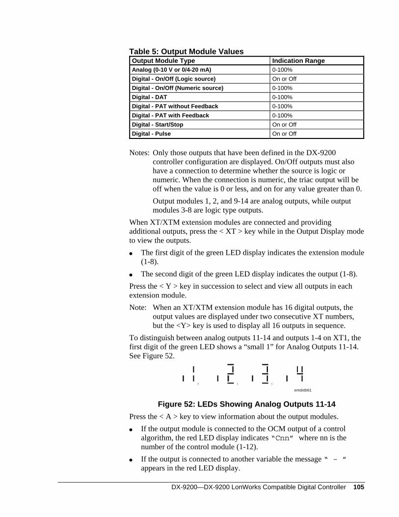
DX-9200—DX-9200 LonWorks Compatible Digital Controller 105
Table 5: Output Module Values Output Module Type Indication Range Analog (0-10 V or 0/4-20 mA) 0-100% Digital - On/Off (Logic source) On or Off Digital - On/Off (Numeric source) 0-100% Digital - DAT 0-100% Digital - PAT without Feedback 0-100% Digital - PAT with Feedback 0-100% Digital - Start/Stop On or Off Digital - Pulse On or Off
Notes: Only those outputs that have been defined in the DX-9200
controller configuration are displayed. On/Off outputs must also have a connection to determine whether the source is logic or numeric. When the connection is numeric, the triac output will be off when the value is 0 or less, and on for any value greater than 0.
Output modules 1, 2, and 9-14 are analog outputs, while output modules 3-8 are logic type outputs.
When XT/XTM extension modules are connected and providing additional outputs, press the < XT > key while in the Output Display mode to view the outputs.
The first digit of the green LED display indicates the extension module (1-8).
The second digit of the green LED display indicates the output (1-8). Press the < Y > key in succession to select and view all outputs in each extension module. Note: When an XT/XTM extension module has 16 digital outputs, the
output values are displayed under two consecutive XT numbers, but the <Y> key is used to display all 16 outputs in sequence.
To distinguish between analog outputs 11-14 and outputs 1-4 on XT1, the first digit of the green LED shows a “small 1” for Analog Outputs 11-14. See Figure 52.
emdxtb61
Figure 52: LEDs Showing Analog Outputs 11-14 Press the < A > key to view information about the output modules.
If the output module is connected to the OCM output of a control algorithm, the red LED display indicates “Cnn” where nn is the number of the control module (1-12).
If the output is connected to another variable the message “ – ” appears in the red LED display.
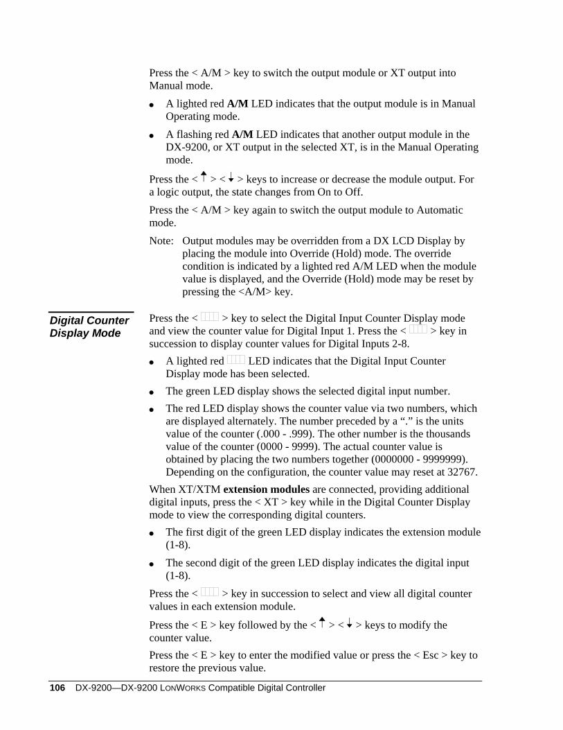
106 DX-9200—DX-9200 LONWORKS Compatible Digital Controller
Press the < A/M > key to switch the output module or XT output into Manual mode.
A lighted red A/M LED indicates that the output module is in Manual Operating mode.
A flashing red A/M LED indicates that another output module in the DX-9200, or XT output in the selected XT, is in the Manual Operating mode.
Press the < > < > keys to increase or decrease the module output. For a logic output, the state changes from On to Off. Press the < A/M > key again to switch the output module to Automatic mode. Note: Output modules may be overridden from a DX LCD Display by
placing the module into Override (Hold) mode. The override condition is indicated by a lighted red A/M LED when the module value is displayed, and the Override (Hold) mode may be reset by pressing the <A/M> key.
Press the < > key to select the Digital Input Counter Display mode and view the counter value for Digital Input 1. Press the < > key in succession to display counter values for Digital Inputs 2-8.
Digital Counter Display Mode
A lighted red LED indicates that the Digital Input Counter Display mode has been selected.
The green LED display shows the selected digital input number. The red LED display shows the counter value via two numbers, which
are displayed alternately. The number preceded by a “.” is the units value of the counter (.000 - .999). The other number is the thousands value of the counter (0000 - 9999). The actual counter value is obtained by placing the two numbers together (0000000 - 9999999). Depending on the configuration, the counter value may reset at 32767.
When XT/XTM extension modules are connected, providing additional digital inputs, press the < XT > key while in the Digital Counter Display mode to view the corresponding digital counters.
The first digit of the green LED display indicates the extension module (1-8).
The second digit of the green LED display indicates the digital input (1-8).
Press the < > key in succession to select and view all digital counter values in each extension module.
Press the < E > key followed by the < > < > keys to modify the counter value. Press the < E > key to enter the modified value or press the < Esc > key to restore the previous value.
DX-9200—DX-9200 LonWorks Compatible Digital Controller 107
Programmable Function Module Display Mode
Operating values and parameters for control, totalization, and sequencer algorithms can be viewed and modified from the front panel. Press the < Z > key to select the Programmable Function Module Display mode and view values and parameters for the first module. Press the < Z > key in succession to view the values and parameters for the other programmable function modules that have been configured as control, totalization, or sequencer modules.
A lighted red Z LED indicates that the Working Setpoint Display mode has been selected.
Control Modules
The green LED display shows the control module number selected. If the control module is a heating/cooling (dual) PID or On/Off module, the control module number and loop number are displayed alternately. The heating loop working setpoint is displayed first with a flashing “L1”. Press the < A > key to view the cooling loop working setpoint with a flashing “L2”. The red LED display shows the working setpoint value for the selected control module.
Press the < E > key, followed by the < > < > keys, to modify the local setpoint of the selected control module. This, in turn, modifies the working setpoint displayed. During the Edit mode the Z LED flashes. To confirm the modification, press the < E > key. To restore the previous value, press the < Esc > key. Note: The working setpoint may only be adjusted within the minimum
and maximum values entered into the control module database. Press the < A > key to view auxiliary information on the working setpoint. Press the < A > key to view the process variable value for the selected control module. The red Z LED is lit and the red X LED flashes. Press the < A > key a second time to view the output of the selected control module. The red Z LED is lit and the red Y LED flashes. Press the < A/M > key to switch the control module to Manual mode.
A lighted red A/M LED indicates that the control module is in the Manual mode.
A flashing red A/M LED indicates that another control module is in the Manual mode.
Press the < > < > keys to increase or decrease control module output. Press the < A/M > key again to switch the control module back to Automatic mode.
108 DX-9200—DX-9200 LONWORKS Compatible Digital Controller
Press the < A > key in succession to view further parameters as follows:
Proportional band (flashing “P,” “P1,” or “P2” in the green LED display).
PID Control Modules
Reset action in repeats/minute (flashing “i,” “i1,” or “i2” in the green LED display). Rate (derivative) action decay time in minutes (flashing “d,” “d1,” or “d2” in the green LED display). Standby bias (flashing “b,” “b1,” or “b2” in the green LED display). Off bias (flashing “o,” “o1,” or “o2” in the green LED display).
Control action (flashing “A,” “A1,” or “A2” in the green LED display).
On/Off Control Modules
Differential (flashing “d,” “d1,” or “d2” in the green LED display). Standby bias (flashing “b,” “b1,” or “b2” in the green LED display). Off bias (flashing “o,” “o1,” or “o2” in the green LED display).
Press the < E > key, followed by the < > < > keys, to increase or decrease the parameters displayed. Press the < E > key to save the modified value, or press the < Esc > key to restore the previous value.
A lighted red Z LED and a flashing red Y LED indicate that the Totalization Module Output Value Display mode has been selected.
Totalization Modules
The green LED display shows, alternately, the programmable function module number selected and the totalization module channel number “t1”.
The red LED display shows the totalized value for the selected module and Channel 1.
Press the < A > key to view the totalized output values of Channels 2 to 8.
The green LED display shows, alternately, the programmable function module number selected and the totalization module channel number “t2”, “t3”, up to “t8”.
The red LED display shows the totalized value for the selected module and channel.
DX-9200—DX-9200 LonWorks Compatible Digital Controller 109
Whenever a totalized value is being displayed, the < A/M > key may be pressed to set the channel to Manual mode.
A lighted red A/M LED indicates that the channel is in the Manual mode.
A flashing red A/M LED indicates that another module or channel is in the Manual mode.
Press the < > < > keys to increase or decrease (reset to 0, for example) the totalized value. Press the < A/M > key again to set the channel back to Automatic mode. The totalized value set in Manual mode is maintained as the initial value for the continuing totalizing operation.
If any channel has been configured with the accumulator option, the total accumulated value for this channel is displayed after the display of the totalized value (t1-t8) when the < A > key is pressed.
Special Option for Totalization Channel Accumulator
The green LED display shows, alternately, the programmable function module number selected and the totalization module channel number, displayed as “A1” to “A8” to indicate the accumulated value. The red LED display shows the accumulated value for the selected module and channel. Two numbers flash alternately. The number preceded by a “.” represents units and the other number represents thousands of units. An accumulated value of up to 9999999 is displayed with the two alternate displays of “9999” and “.999”. Depending on the configuration, the accumulated value may reset at 32767. Whenever an accumulated value is being displayed, press the < E > key to edit the value or to reset it to 0. A flashing Z LED indicates Edit mode.
Press the < > < > keys to modify the displayed value. Press the < E > key to enter the modified value or the < Esc > key to retain the original value. Note: The DX-9200 controller automatically increments the
accumulated value each time the totalized value reaches a configured limit. In this case the totalized value may be regarded as a fine resolution (or a Vernier scale) for the accumulated value.
A lighted red Z LED and a flashing red Y LED indicate that the Sequencer Module Requested Output Value Display mode has been selected.
Sequencer Module
The green LED display shows the programmable function module number selected.
The red LED display shows the requested output value for the selected module.
110 DX-9200—DX-9200 LONWORKS Compatible Digital Controller
Press the < A/M > key to set the module to Manual mode. A lighted red A/M LED indicates that the module is in the Manual
mode. A flashing red A/M LED indicates that another module is in the
Manual mode.
Press the < > < > keys to increase or decrease the output value. Press the < A/M > key again to set the module back to Automatic mode. Press the < A > key to view the totalized run time (in hours) of the sets in the selected sequencer module.
The green LED display shows the sequencer stage number of the first stage in each set with an “r” prefix for single digit numbers.
The red LED display shows the totalized run time value via two numbers, which are displayed alternately. The number preceded by a “.” is the units value of the run time (.000 - .999). The other number is the thousands value of the run time (0000 - 9999). The full run time value is obtained by placing the two numbers together (0000000 - 9999999).
Press the < E > key, followed by the < > < > keys, to modify the run time value displayed (reset to zero, for example). Press the < E > key to save the modified value, or press the < Esc > key to restore the previous value. Press the < A > key to successively view and modify the run time values of all sets in the module.
Press the < E > key, followed by the < > < > keys, to increase or decrease the parameters displayed. Press the < E > key to save the modified value, or press the < Esc > key to restore the previous value.
Press the <K> key to select the Analog/Digital Constant Display mode. A lighted red K LED indicates that the Analog/Digital Function Display mode has been selected.
Analog/Digital Constant Display Mode
Press the <K> key in succession to view first the eight analog constants followed by the digital constants.
Press the <E> key followed by the < > < > keys to modify the selected analog or digital constant. During the Edit mode the K LED flashes. Press the < E > key to save the modified value, or press the < Esc > key to restore the previous value. Note: Changes made to analog and digital constants remain until another
change is made from the front panel or from a DX LCD Display. The originally downloaded values can only be restored by a new download.
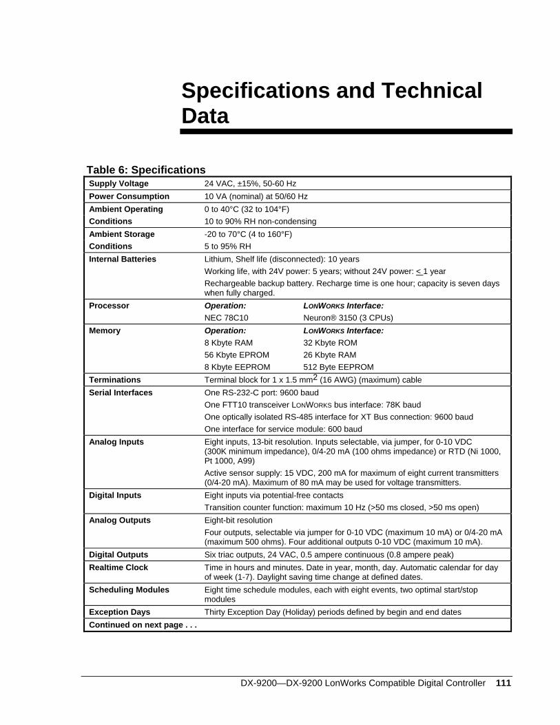
DX-9200—DX-9200 LonWorks Compatible Digital Controller 111
Specifications and Technical Data
Table 6: Specifications Supply Voltage 24 VAC, ±15%, 50-60 Hz Power Consumption 10 VA (nominal) at 50/60 Hz Ambient Operating 0 to 40°C (32 to 104°F) Conditions 10 to 90% RH non-condensing Ambient Storage -20 to 70°C (4 to 160°F) Conditions 5 to 95% RH Internal Batteries Lithium, Shelf life (disconnected): 10 years
Working life, with 24V power: 5 years; without 24V power: < 1 year Rechargeable backup battery. Recharge time is one hour; capacity is seven days when fully charged.
Processor Operation: LONWORKS Interface: NEC 78C10 Neuron® 3150 (3 CPUs)
Memory Operation: LONWORKS Interface: 8 Kbyte RAM 32 Kbyte ROM 56 Kbyte EPROM 26 Kbyte RAM 8 Kbyte EEPROM 512 Byte EEPROM
Terminations Terminal block for 1 x 1.5 mm2 (16 AWG) (maximum) cable Serial Interfaces One RS-232-C port: 9600 baud
One FTT10 transceiver LONWORKS bus interface: 78K baud One optically isolated RS-485 interface for XT Bus connection: 9600 baud One interface for service module: 600 baud
Analog Inputs Eight inputs, 13-bit resolution. Inputs selectable, via jumper, for 0-10 VDC (300K minimum impedance), 0/4-20 mA (100 ohms impedance) or RTD (Ni 1000, Pt 1000, A99) Active sensor supply: 15 VDC, 200 mA for maximum of eight current transmitters (0/4-20 mA). Maximum of 80 mA may be used for voltage transmitters.
Digital Inputs Eight inputs via potential-free contacts Transition counter function: maximum 10 Hz (>50 ms closed, >50 ms open)
Analog Outputs Eight-bit resolution Four outputs, selectable via jumper for 0-10 VDC (maximum 10 mA) or 0/4-20 mA (maximum 500 ohms). Four additional outputs 0-10 VDC (maximum 10 mA).
Digital Outputs Six triac outputs, 24 VAC, 0.5 ampere continuous (0.8 ampere peak) Realtime Clock Time in hours and minutes. Date in year, month, day. Automatic calendar for day
of week (1-7). Daylight saving time change at defined dates. Scheduling Modules Eight time schedule modules, each with eight events, two optimal start/stop
modules Exception Days Thirty Exception Day (Holiday) periods defined by begin and end dates Continued on next page . . .
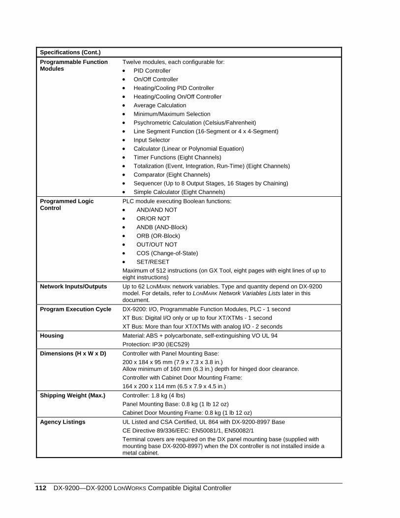
112 DX-9200—DX-9200 LONWORKS Compatible Digital Controller
Specifications (Cont.) Programmable Function Modules
Twelve modules, each configurable for: • PID Controller • On/Off Controller • Heating/Cooling PID Controller • Heating/Cooling On/Off Controller • Average Calculation • Minimum/Maximum Selection • Psychrometric Calculation (Celsius/Fahrenheit) • Line Segment Function (16-Segment or 4 x 4-Segment) • Input Selector • Calculator (Linear or Polynomial Equation) • Timer Functions (Eight Channels) • Totalization (Event, Integration, Run-Time) (Eight Channels) • Comparator (Eight Channels) • Sequencer (Up to 8 Output Stages, 16 Stages by Chaining) • Simple Calculator (Eight Channels)
Programmed Logic Control
PLC module executing Boolean functions: • AND/AND NOT • OR/OR NOT • ANDB (AND-Block) • ORB (OR-Block) • OUT/OUT NOT • COS (Change-of-State) • SET/RESET Maximum of 512 instructions (on GX Tool, eight pages with eight lines of up to eight instructions)
Network Inputs/Outputs Up to 62 LONMARK network variables. Type and quantity depend on DX-9200 model. For details, refer to LONMARK Network Variables Lists later in this document.
Program Execution Cycle DX-9200: I/O, Programmable Function Modules, PLC - 1 second XT Bus: Digital I/O only or up to four XT/XTMs - 1 second XT Bus: More than four XT/XTMs with analog I/O - 2 seconds
Housing Material: ABS + polycarbonate, self-extinguishing VO UL 94 Protection: IP30 (IEC529)
Dimensions (H x W x D) Controller with Panel Mounting Base: 200 x 184 x 95 mm (7.9 x 7.3 x 3.8 in.) Allow minimum of 160 mm (6.3 in.) depth for hinged door clearance. Controller with Cabinet Door Mounting Frame: 164 x 200 x 114 mm (6.5 x 7.9 x 4.5 in.)
Shipping Weight (Max.) Controller: 1.8 kg (4 lbs) Panel Mounting Base: 0.8 kg (1 lb 12 oz) Cabinet Door Mounting Frame: 0.8 kg (1 lb 12 oz)
Agency Listings UL Listed and CSA Certified, UL 864 with DX-9200-8997 Base CE Directive 89/336/EEC: EN50081/1, EN50082/1 Terminal covers are required on the DX panel mounting base (supplied with mounting base DX-9200-8997) when the DX controller is not installed inside a metal cabinet.
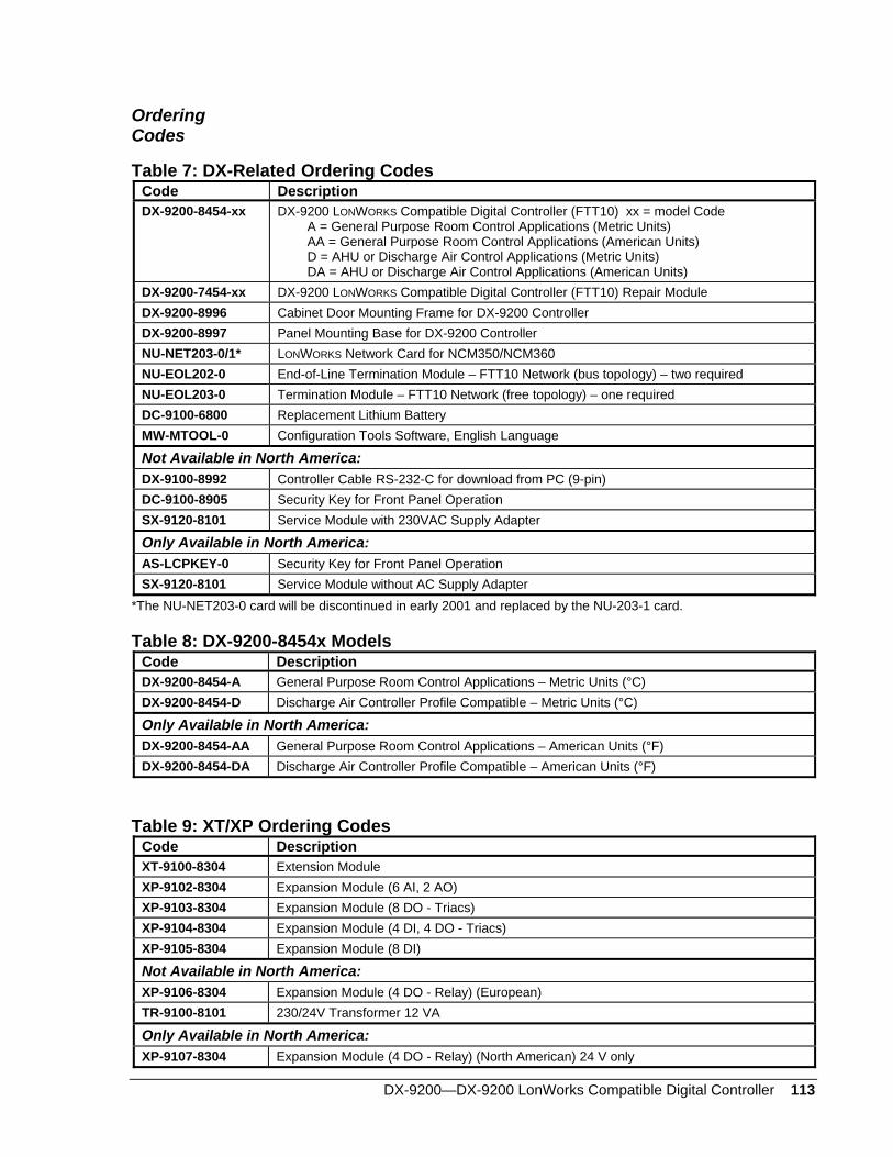
DX-9200—DX-9200 LonWorks Compatible Digital Controller 113
Ordering Codes
Table 7: DX-Related Ordering Codes Code Description DX-9200-8454-xx DX-9200 LONWORKS Compatible Digital Controller (FTT10) xx = model Code
A = General Purpose Room Control Applications (Metric Units) AA = General Purpose Room Control Applications (American Units) D = AHU or Discharge Air Control Applications (Metric Units) DA = AHU or Discharge Air Control Applications (American Units)
DX-9200-7454-xx DX-9200 LONWORKS Compatible Digital Controller (FTT10) Repair Module DX-9200-8996 Cabinet Door Mounting Frame for DX-9200 Controller DX-9200-8997 Panel Mounting Base for DX-9200 Controller NU-NET203-0/1* LONWORKS Network Card for NCM350/NCM360 NU-EOL202-0 End-of-Line Termination Module – FTT10 Network (bus topology) – two required NU-EOL203-0 Termination Module – FTT10 Network (free topology) – one required DC-9100-6800 Replacement Lithium Battery MW-MTOOL-0 Configuration Tools Software, English Language
Not Available in North America: DX-9100-8992 Controller Cable RS-232-C for download from PC (9-pin) DC-9100-8905 Security Key for Front Panel Operation SX-9120-8101 Service Module with 230VAC Supply Adapter
Only Available in North America: AS-LCPKEY-0 Security Key for Front Panel Operation SX-9120-8101 Service Module without AC Supply Adapter
*The NU-NET203-0 card will be discontinued in early 2001 and replaced by the NU-203-1 card.
Table 8: DX-9200-8454x Models Code Description DX-9200-8454-A General Purpose Room Control Applications – Metric Units (°C) DX-9200-8454-D Discharge Air Controller Profile Compatible – Metric Units (°C)
Only Available in North America: DX-9200-8454-AA General Purpose Room Control Applications – American Units (°F) DX-9200-8454-DA Discharge Air Controller Profile Compatible – American Units (°F)
Table 9: XT/XP Ordering Codes Code Description XT-9100-8304 Extension Module XP-9102-8304 Expansion Module (6 AI, 2 AO) XP-9103-8304 Expansion Module (8 DO - Triacs) XP-9104-8304 Expansion Module (4 DI, 4 DO - Triacs) XP-9105-8304 Expansion Module (8 DI)
Not Available in North America: XP-9106-8304 Expansion Module (4 DO - Relay) (European) TR-9100-8101 230/24V Transformer 12 VA
Only Available in North America: XP-9107-8304 Expansion Module (4 DO - Relay) (North American) 24 V only
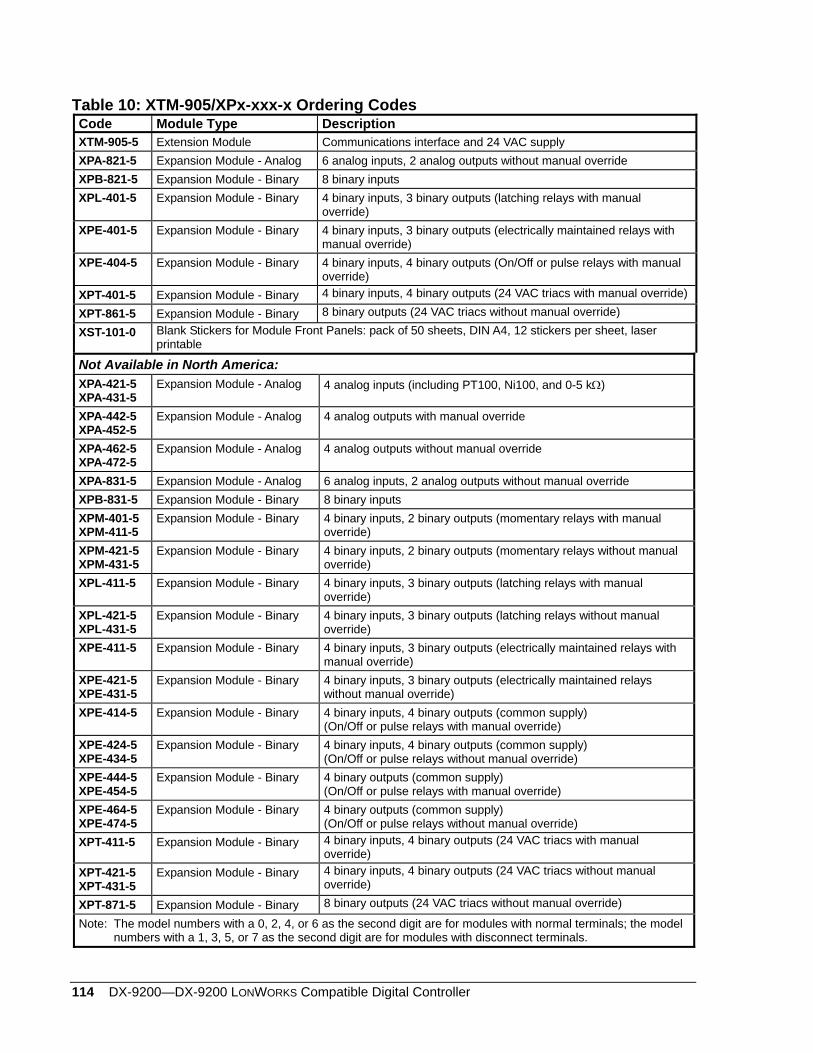
114 DX-9200—DX-9200 LONWORKS Compatible Digital Controller
Table 10: XTM-905/XPx-xxx-x Ordering Codes Code Module Type Description XTM-905-5 Extension Module Communications interface and 24 VAC supply XPA-821-5 Expansion Module - Analog 6 analog inputs, 2 analog outputs without manual override XPB-821-5 Expansion Module - Binary 8 binary inputs XPL-401-5 Expansion Module - Binary 4 binary inputs, 3 binary outputs (latching relays with manual
override) XPE-401-5 Expansion Module - Binary 4 binary inputs, 3 binary outputs (electrically maintained relays with
manual override) XPE-404-5 Expansion Module - Binary 4 binary inputs, 4 binary outputs (On/Off or pulse relays with manual
override) XPT-401-5 Expansion Module - Binary 4 binary inputs, 4 binary outputs (24 VAC triacs with manual override)
XPT-861-5 Expansion Module - Binary 8 binary outputs (24 VAC triacs without manual override)
XST-101-0 Blank Stickers for Module Front Panels: pack of 50 sheets, DIN A4, 12 stickers per sheet, laser printable
Not Available in North America: XPA-421-5 XPA-431-5
Expansion Module - Analog 4 analog inputs (including PT100, Ni100, and 0-5 kΩ)
XPA-442-5 XPA-452-5
Expansion Module - Analog 4 analog outputs with manual override
XPA-462-5 XPA-472-5
Expansion Module - Analog 4 analog outputs without manual override
XPA-831-5 Expansion Module - Analog 6 analog inputs, 2 analog outputs without manual override XPB-831-5 Expansion Module - Binary 8 binary inputs XPM-401-5 XPM-411-5
Expansion Module - Binary 4 binary inputs, 2 binary outputs (momentary relays with manual override)
XPM-421-5 XPM-431-5
Expansion Module - Binary 4 binary inputs, 2 binary outputs (momentary relays without manual override)
XPL-411-5 Expansion Module - Binary 4 binary inputs, 3 binary outputs (latching relays with manual override)
XPL-421-5 XPL-431-5
Expansion Module - Binary 4 binary inputs, 3 binary outputs (latching relays without manual override)
XPE-411-5 Expansion Module - Binary 4 binary inputs, 3 binary outputs (electrically maintained relays with manual override)
XPE-421-5 XPE-431-5
Expansion Module - Binary 4 binary inputs, 3 binary outputs (electrically maintained relays without manual override)
XPE-414-5 Expansion Module - Binary 4 binary inputs, 4 binary outputs (common supply) (On/Off or pulse relays with manual override)
XPE-424-5 XPE-434-5
Expansion Module - Binary 4 binary inputs, 4 binary outputs (common supply) (On/Off or pulse relays without manual override)
XPE-444-5 XPE-454-5
Expansion Module - Binary 4 binary outputs (common supply) (On/Off or pulse relays with manual override)
XPE-464-5 XPE-474-5
Expansion Module - Binary 4 binary outputs (common supply) (On/Off or pulse relays without manual override)
XPT-411-5 Expansion Module - Binary 4 binary inputs, 4 binary outputs (24 VAC triacs with manual override)
XPT-421-5 XPT-431-5
Expansion Module - Binary 4 binary inputs, 4 binary outputs (24 VAC triacs without manual override)
XPT-871-5 Expansion Module - Binary 8 binary outputs (24 VAC triacs without manual override)
Note: The model numbers with a 0, 2, 4, or 6 as the second digit are for modules with normal terminals; the model numbers with a 1, 3, 5, or 7 as the second digit are for modules with disconnect terminals.
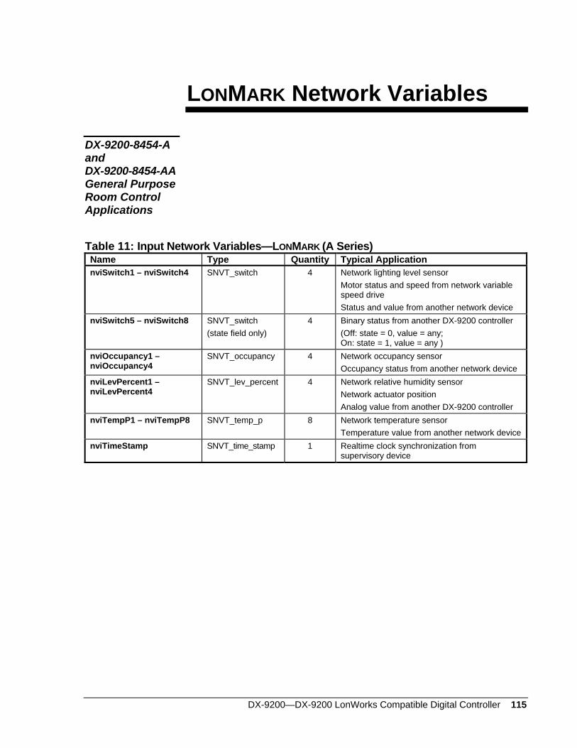
DX-9200—DX-9200 LonWorks Compatible Digital Controller 115
LONMARK Network Variables
DX-9200-8454-A and DX-9200-8454-AA General Purpose Room Control Applications
Table 11: Input Network Variables—LONMARK (A Series) Name Type Quantity Typical Application nviSwitch1 – nviSwitch4 SNVT_switch 4 Network lighting level sensor
Motor status and speed from network variable speed drive Status and value from another network device
nviSwitch5 – nviSwitch8 SNVT_switch (state field only)
4 Binary status from another DX-9200 controller (Off: state = 0, value = any; On: state = 1, value = any )
nviOccupancy1 – nviOccupancy4
SNVT_occupancy 4 Network occupancy sensor Occupancy status from another network device
nviLevPercent1 – nviLevPercent4
SNVT_lev_percent 4 Network relative humidity sensor Network actuator position Analog value from another DX-9200 controller
nviTempP1 – nviTempP8 SNVT_temp_p 8 Network temperature sensor Temperature value from another network device
nviTimeStamp SNVT_time_stamp 1 Realtime clock synchronization from supervisory device
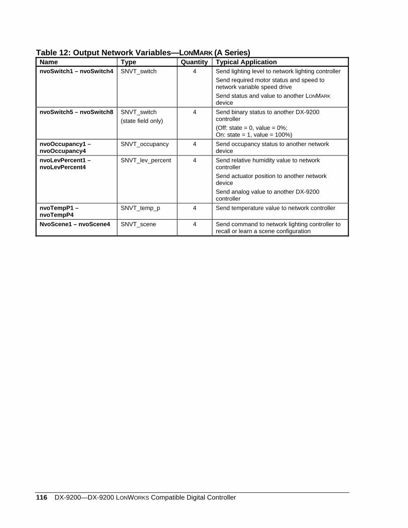
116 DX-9200—DX-9200 LONWORKS Compatible Digital Controller
Table 12: Output Network Variables—LONMARK (A Series) Name Type Quantity Typical Application nvoSwitch1 – nvoSwitch4 SNVT_switch 4 Send lighting level to network lighting controller
Send required motor status and speed to network variable speed drive Send status and value to another LONMARK device
nvoSwitch5 – nvoSwitch8 SNVT_switch (state field only)
4 Send binary status to another DX-9200 controller (Off: state = 0, value = 0%; On: state = 1, value = 100%)
nvoOccupancy1 – nvoOccupancy4
SNVT_occupancy 4 Send occupancy status to another network device
nvoLevPercent1 – nvoLevPercent4
SNVT_lev_percent 4 Send relative humidity value to network controller Send actuator position to another network device Send analog value to another DX-9200 controller
nvoTempP1 – nvoTempP4
SNVT_temp_p 4 Send temperature value to network controller
NvoScene1 – nvoScene4 SNVT_scene 4 Send command to network lighting controller to recall or learn a scene configuration
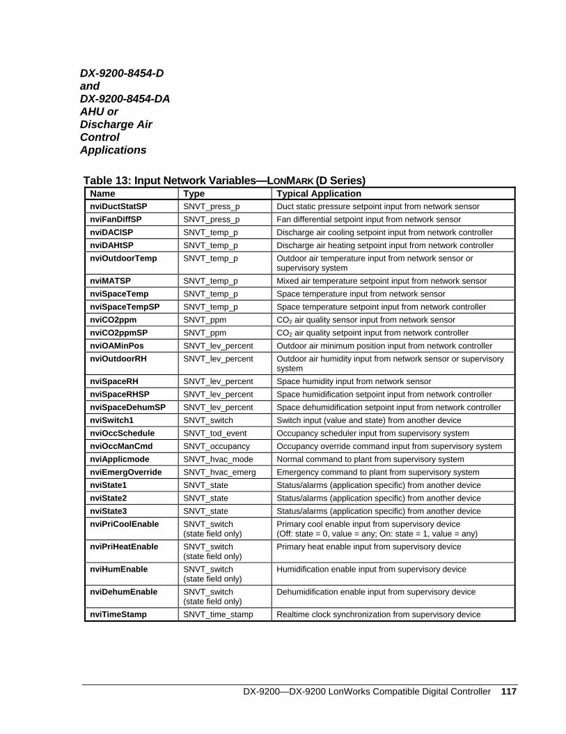
DX-9200—DX-9200 LonWorks Compatible Digital Controller 117
DX-9200-8454-D and DX-9200-8454-DA AHU or Discharge Air Control Applications
Table 13: Input Network Variables—LONMARK (D Series) Name Type Typical Application nviDuctStatSP SNVT_press_p Duct static pressure setpoint input from network sensor nviFanDiffSP SNVT_press_p Fan differential setpoint input from network sensor nviDAClSP SNVT_temp_p Discharge air cooling setpoint input from network controller nviDAHtSP SNVT_temp_p Discharge air heating setpoint input from network controller nviOutdoorTemp SNVT_temp_p Outdoor air temperature input from network sensor or
supervisory system nviMATSP SNVT_temp_p Mixed air temperature setpoint input from network sensor nviSpaceTemp SNVT_temp_p Space temperature input from network sensor nviSpaceTempSP SNVT_temp_p Space temperature setpoint input from network controller nviCO2ppm SNVT_ppm CO2 air quality sensor input from network sensor nviCO2ppmSP SNVT_ppm CO2 air quality setpoint input from network controller nviOAMinPos SNVT_lev_percent Outdoor air minimum position input from network controller nviOutdoorRH SNVT_lev_percent Outdoor air humidity input from network sensor or supervisory
system nviSpaceRH SNVT_lev_percent Space humidity input from network sensor nviSpaceRHSP SNVT_lev_percent Space humidification setpoint input from network controller nviSpaceDehumSP SNVT_lev_percent Space dehumidification setpoint input from network controller nviSwitch1 SNVT_switch Switch input (value and state) from another device nviOccSchedule SNVT_tod_event Occupancy scheduler input from supervisory system nviOccManCmd SNVT_occupancy Occupancy override command input from supervisory system nviApplicmode SNVT_hvac_mode Normal command to plant from supervisory system nviEmergOverride SNVT_hvac_emerg Emergency command to plant from supervisory system nviState1 SNVT_state Status/alarms (application specific) from another device nviState2 SNVT_state Status/alarms (application specific) from another device nviState3 SNVT_state Status/alarms (application specific) from another device nviPriCoolEnable SNVT_switch
(state field only) Primary cool enable input from supervisory device (Off: state = 0, value = any; On: state = 1, value = any)
nviPriHeatEnable SNVT_switch (state field only)
Primary heat enable input from supervisory device
nviHumEnable SNVT_switch (state field only)
Humidification enable input from supervisory device
nviDehumEnable SNVT_switch (state field only)
Dehumidification enable input from supervisory device
nviTimeStamp SNVT_time_stamp Realtime clock synchronization from supervisory device
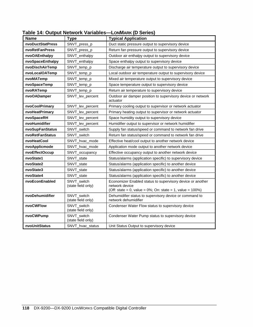
118 DX-9200—DX-9200 LONWORKS Compatible Digital Controller
Table 14: Output Network Variables—LONMARK (D Series) Name Type Typical Application nvoDuctStatPress SNVT_press_p Duct static pressure output to supervisory device nvoRetFanPress SNVT_press_p Return fan pressure output to supervisory device nvoOAEnthalpy SNVT_enthalpy Outdoor air enthalpy output to supervisory device nvoSpaceEnthalpy SNVT_enthalpy Space enthalpy output to supervisory device nvoDischAirTemp SNVT_temp_p Discharge air temperature output to supervisory device nvoLocalOATemp SNVT_temp_p Local outdoor air temperature output to supervisory device nvoMATemp SNVT_temp_p Mixed air temperature output to supervisory device nvoSpaceTemp SNVT_temp_p Space temperature output to supervisory device nvoRATemp SNVT_temp_p Return air temperature to supervisory device nvoOADamper SNVT_lev_percent Outdoor air damper position to supervisory device or network
actuator nvoCoolPrimary SNVT_lev_percent Primary cooling output to supervisor or network actuator nvoHeatPrimary SNVT_lev_percent Primary heating output to supervisor or network actuator nvoSpaceRH SNVT_lev_percent Space humidity output to supervisory device nvoHumidifier SNVT_lev_percent Humidifier output to supervisor or network humidifier nvoSupFanStatus SNVT_switch Supply fan status/speed or command to network fan drive nvoRetFanStatus SNVT_switch Return fan status/speed or command to network fan drive nvoHeatCool SNVT_hvac_mode Effective heat/cool output to another network device nvoApplicmode SNVT_hvac_mode Application mode output to another network device nvoEffectOccup SNVT_occupancy Effective occupancy output to another network device nvoState1 SNVT_state Status/alarms (application specific) to supervisory device nvoState2 SNVT_state Status/alarms (application specific) to another device nvoState3 SNVT_state Status/alarms (application specific) to another device nvoState4 SNVT_state Status/alarms (application specific) to another device nvoEconEnabled SNVT_switch
(state field only) Economizer Enabled status to supervisory device or another network device (Off: state = 0, value = 0%; On: state = 1, value = 100%)
nvoDehumidifier SNVT_switch (state field only)
Dehumidifier status to supervisory device or command to network dehumidifier
nvoCWFlow SNVT_switch (state field only)
Condenser Water Flow status to supervisory device
nvoCWPump SNVT_switch (state field only)
Condenser Water Pump status to supervisory device
nvoUnitStatus SNVT_hvac_status Unit Status Output to supervisory device
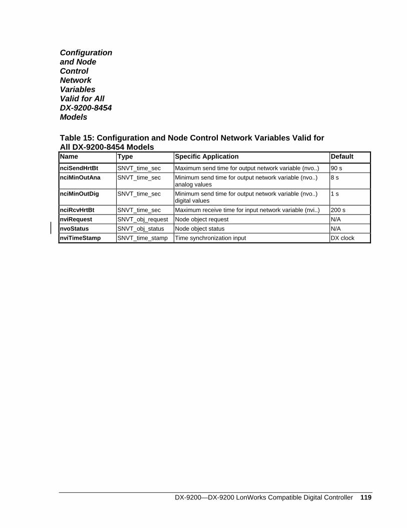
DX-9200—DX-9200 LonWorks Compatible Digital Controller 119
Configuration and Node Control Network Variables Valid for All DX-9200-8454 Models
Table 15: Configuration and Node Control Network Variables Valid for All DX-9200-8454 Models Name Type Specific Application Default nciSendHrtBt SNVT_time_sec Maximum send time for output network variable (nvo..) 90 s nciMinOutAna SNVT_time_sec Minimum send time for output network variable (nvo..)
analog values 8 s
nciMinOutDig SNVT_time_sec Minimum send time for output network variable (nvo..) digital values
1 s
nciRcvHrtBt SNVT_time_sec Maximum receive time for input network variable (nvi..) 200 s nviRequest SNVT_obj_request Node object request N/A nvoStatus SNVT_obj_status Node object status N/A nviTimeStamp SNVT_time_stamp Time synchronization input DX clock

120 DX-9200—DX-9200 LONWORKS Compatible Digital Controller
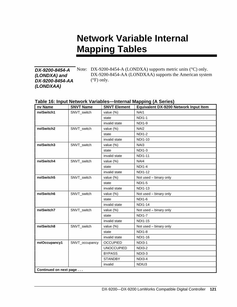
DX-9200—DX-9200 LonWorks Compatible Digital Controller 121
Network Variable Internal Mapping Tables
Note: DX-9200-8454-A (LONDXA) supports metric units (°C) only. DX-9200-8454-AA (LONDXAA) supports the American system (°F) only.
DX-9200-8454-A (LONDXA) and DX-9200-8454-AA (LONDXAA)
Table 16: Input Network Variables—Internal Mapping (A Series) nv Name SNVT Name SNVT Element Equivalent DX-9200 Network Input Item nviSwitch1 SNVT_switch value (%) NAI1 state NDI1-1 invalid state NDI1-9 nviSwitch2 SNVT_switch value (%) NAI2 state NDI1-2 invalid state NDI1-10 nviSwitch3 SNVT_switch value (%) NAI3 state NDI1-3 invalid state NDI1-11 nviSwitch4 SNVT_switch value (%) NAI4 state NDI1-4 invalid state NDI1-12 nviSwitch5 SNVT_switch value (%) Not used – binary only state NDI1-5 invalid state NDI1-13 nviSwitch6 SNVT_switch value (%) Not used – binary only state NDI1-6 invalid state NDI1-14 nviSwitch7 SNVT_switch value (%) Not used – binary only state NDI1-7 invalid state NDI1-15 nviSwitch8 SNVT_switch value (%) Not used – binary only state NDI1-8 invalid state NDI1-16 nviOccupancy1 SNVT_occupancy OCCUPIED NDI3-1 UNOCCUPIED NDI3-2 BYPASS NDI3-3 STANDBY NDI3-4 invalid NDIU3 Continued on next page . . .
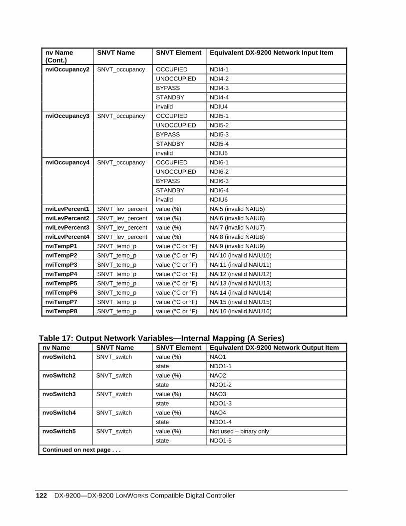
122 DX-9200—DX-9200 LONWORKS Compatible Digital Controller
nv Name (Cont.)
SNVT Name SNVT Element Equivalent DX-9200 Network Input Item
nviOccupancy2 SNVT_occupancy OCCUPIED NDI4-1 UNOCCUPIED NDI4-2 BYPASS NDI4-3 STANDBY NDI4-4 invalid NDIU4 nviOccupancy3 SNVT_occupancy OCCUPIED NDI5-1 UNOCCUPIED NDI5-2 BYPASS NDI5-3 STANDBY NDI5-4 invalid NDIU5 nviOccupancy4 SNVT_occupancy OCCUPIED NDI6-1 UNOCCUPIED NDI6-2 BYPASS NDI6-3 STANDBY NDI6-4 invalid NDIU6 nviLevPercent1 SNVT_lev_percent value (%) NAI5 (invalid NAIU5) nviLevPercent2 SNVT_lev_percent value (%) NAI6 (invalid NAIU6) nviLevPercent3 SNVT_lev_percent value (%) NAI7 (invalid NAIU7) nviLevPercent4 SNVT_lev_percent value (%) NAI8 (invalid NAIU8) nviTempP1 SNVT_temp_p value (°C or °F) NAI9 (invalid NAIU9) nviTempP2 SNVT_temp_p value (°C or °F) NAI10 (invalid NAIU10) nviTempP3 SNVT_temp_p value (°C or °F) NAI11 (invalid NAIU11) nviTempP4 SNVT_temp_p value (°C or °F) NAI12 (invalid NAIU12) nviTempP5 SNVT_temp_p value (°C or °F) NAI13 (invalid NAIU13) nviTempP6 SNVT_temp_p value (°C or °F) NAI14 (invalid NAIU14) nviTempP7 SNVT_temp_p value (°C or °F) NAI15 (invalid NAIU15) nviTempP8 SNVT_temp_p value (°C or °F) NAI16 (invalid NAIU16)
Table 17: Output Network Variables—Internal Mapping (A Series) nv Name SNVT Name SNVT Element Equivalent DX-9200 Network Output Item nvoSwitch1 SNVT_switch value (%) NAO1 state NDO1-1 nvoSwitch2 SNVT_switch value (%) NAO2 state NDO1-2 nvoSwitch3 SNVT_switch value (%) NAO3 state NDO1-3 nvoSwitch4 SNVT_switch value (%) NAO4 state NDO1-4 nvoSwitch5 SNVT_switch value (%) Not used – binary only state NDO1-5 Continued on next page . . .
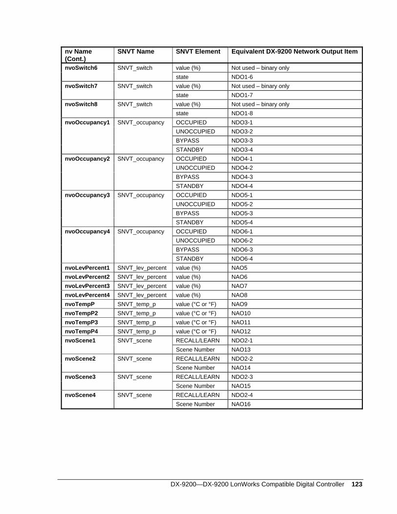
DX-9200—DX-9200 LonWorks Compatible Digital Controller 123
nv Name (Cont.)
SNVT Name SNVT Element Equivalent DX-9200 Network Output Item
nvoSwitch6 SNVT_switch value (%) Not used – binary only state NDO1-6 nvoSwitch7 SNVT_switch value (%) Not used – binary only state NDO1-7 nvoSwitch8 SNVT_switch value (%) Not used – binary only state NDO1-8 nvoOccupancy1 SNVT_occupancy OCCUPIED NDO3-1 UNOCCUPIED NDO3-2 BYPASS NDO3-3 STANDBY NDO3-4 nvoOccupancy2 SNVT_occupancy OCCUPIED NDO4-1 UNOCCUPIED NDO4-2 BYPASS NDO4-3 STANDBY NDO4-4 nvoOccupancy3 SNVT_occupancy OCCUPIED NDO5-1 UNOCCUPIED NDO5-2 BYPASS NDO5-3 STANDBY NDO5-4 nvoOccupancy4 SNVT_occupancy OCCUPIED NDO6-1 UNOCCUPIED NDO6-2 BYPASS NDO6-3 STANDBY NDO6-4 nvoLevPercent1 SNVT_lev_percent value (%) NAO5 nvoLevPercent2 SNVT_lev_percent value (%) NAO6 nvoLevPercent3 SNVT_lev_percent value (%) NAO7 nvoLevPercent4 SNVT_lev_percent value (%) NAO8 nvoTempP SNVT_temp_p value (°C or °F) NAO9 nvoTempP2 SNVT_temp_p value (°C or °F) NAO10 nvoTempP3 SNVT_temp_p value (°C or °F) NAO11 nvoTempP4 SNVT_temp_p value (°C or °F) NAO12 nvoScene1 SNVT_scene RECALL/LEARN NDO2-1 Scene Number NAO13 nvoScene2 SNVT_scene RECALL/LEARN NDO2-2 Scene Number NAO14 nvoScene3 SNVT_scene RECALL/LEARN NDO2-3 Scene Number NAO15 nvoScene4 SNVT_scene RECALL/LEARN NDO2-4 Scene Number NAO16
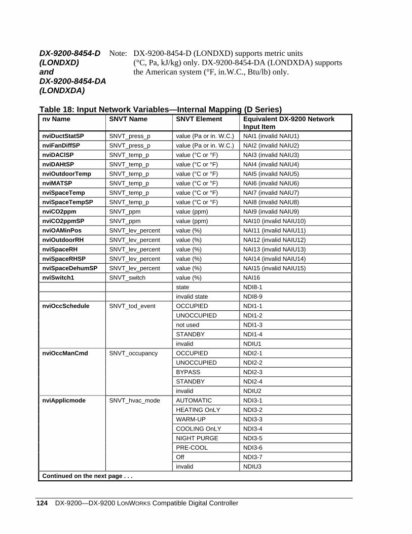
124 DX-9200—DX-9200 LONWORKS Compatible Digital Controller
DX-9200-8454-D (LONDXD) and DX-9200-8454-DA (LONDXDA)
Note: DX-9200-8454-D (LONDXD) supports metric units (°C, Pa, kJ/kg) only. DX-9200-8454-DA (LONDXDA) supports the American system (°F, in.W.C., Btu/lb) only.
Table 18: Input Network Variables—Internal Mapping (D Series) nv Name SNVT Name SNVT Element Equivalent DX-9200 Network
Input Item nviDuctStatSP SNVT_press_p value (Pa or in. W.C.) NAI1 (invalid NAIU1) nviFanDiffSP SNVT_press_p value (Pa or in. W.C.) NAI2 (invalid NAIU2) nviDAClSP SNVT_temp_p value (°C or °F) NAI3 (invalid NAIU3) nviDAHtSP SNVT_temp_p value (°C or °F) NAI4 (invalid NAIU4) nviOutdoorTemp SNVT_temp_p value (°C or °F) NAI5 (invalid NAIU5) nviMATSP SNVT_temp_p value (°C or °F) NAI6 (invalid NAIU6) nviSpaceTemp SNVT_temp_p value (°C or °F) NAI7 (invalid NAIU7) nviSpaceTempSP SNVT_temp_p value (°C or °F) NAI8 (invalid NAIU8) nviCO2ppm SNVT_ppm value (ppm) NAI9 (invalid NAIU9) nviCO2ppmSP SNVT_ppm value (ppm) NAI10 (invalid NAIU10) nviOAMinPos SNVT_lev_percent value (%) NAI11 (invalid NAIU11) nviOutdoorRH SNVT_lev_percent value (%) NAI12 (invalid NAIU12) nviSpaceRH SNVT_lev_percent value (%) NAI13 (invalid NAIU13) nviSpaceRHSP SNVT_lev_percent value (%) NAI14 (invalid NAIU14) nviSpaceDehumSP SNVT_lev_percent value (%) NAI15 (invalid NAIU15) nviSwitch1 SNVT_switch value (%) NAI16 state NDI8-1 invalid state NDI8-9 nviOccSchedule SNVT_tod_event OCCUPIED NDI1-1 UNOCCUPIED NDI1-2 not used NDI1-3 STANDBY NDI1-4 invalid NDIU1 nviOccManCmd SNVT_occupancy OCCUPIED NDI2-1 UNOCCUPIED NDI2-2 BYPASS NDI2-3 STANDBY NDI2-4 invalid NDIU2 nviApplicmode SNVT_hvac_mode AUTOMATIC NDI3-1 HEATING OnLY NDI3-2 WARM-UP NDI3-3 COOLING OnLY NDI3-4 NIGHT PURGE NDI3-5 PRE-COOL NDI3-6 Off NDI3-7 invalid NDIU3 Continued on the next page . . .
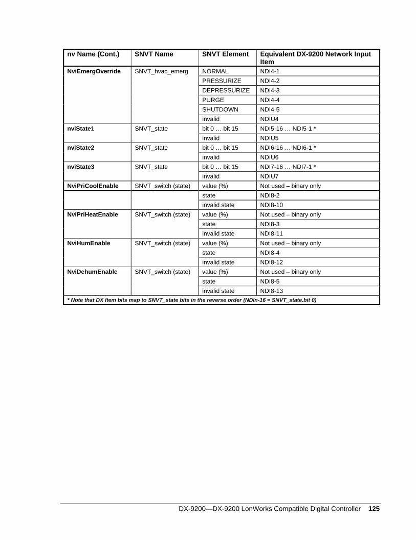
DX-9200—DX-9200 LonWorks Compatible Digital Controller 125
nv Name (Cont.) SNVT Name SNVT Element Equivalent DX-9200 Network Input Item
NviEmergOverride SNVT_hvac_emerg NORMAL NDI4-1 PRESSURIZE NDI4-2 DEPRESSURIZE NDI4-3 PURGE NDI4-4 SHUTDOWN NDI4-5 invalid NDIU4 nviState1 SNVT_state bit 0 … bit 15 NDI5-16 … NDI5-1 * invalid NDIU5 nviState2 SNVT_state bit 0 … bit 15 NDI6-16 … NDI6-1 * invalid NDIU6 nviState3 SNVT_state bit 0 … bit 15 NDI7-16 … NDI7-1 * invalid NDIU7 NviPriCoolEnable SNVT_switch (state) value (%) Not used – binary only state NDI8-2 invalid state NDI8-10 NviPriHeatEnable SNVT_switch (state) value (%) Not used – binary only state NDI8-3 invalid state NDI8-11 NviHumEnable SNVT_switch (state) value (%) Not used – binary only state NDI8-4 invalid state NDI8-12 NviDehumEnable SNVT_switch (state) value (%) Not used – binary only state NDI8-5 invalid state NDI8-13 * Note that DX Item bits map to SNVT_state bits in the reverse order (NDIn-16 = SNVT_state.bit 0)
126 DX-9200—DX-9200 LONWORKS Compatible Digital Controller
Table 19: Output Network Variables—Internal Mapping (D Series) nv Name SNVT Name SNVT Element Equivalent DX-9200 Network
Output Item NvoDuctStatPress SNVT_press_p value (Pa or in. W.C.) NAO1 NvoRetFanPress SNVT_press_p value (Pa or in. W.C.) NAO2 NvoOAEnthalpy SNVT_enthalpy value (kJ/kg or Btu/lb) NAO3 NvoSpaceEnthalpy SNVT_enthalpy value (kJ/kg or Btu/lb) NAO4 NvoDischAirTemp SNVT_temp_p value (°C or °F) NAO5 NvoLocalOATemp SNVT_temp_p value (°C or °F) NAO6 NvoMATemp SNVT_temp_p value (°C or °F) NAO7 NvoSpaceTemp SNVT_temp_p value (°C or °F) NAO8 NvoRATemp SNVT_temp_p value (°C or °F) NAO9 NvoOADamper SNVT_lev_percent value (%) NAO10 NvoCoolPrimary SNVT_lev_percent value (%) NAO11 NvoHeatPrimary SNVT_lev_percent value (%) NAO12 NvoSpaceRH SNVT_lev_percent value (%) NAO13 NvoHumidifier SNVT_lev_percent value (%) NAO14 NvoSupFanStatus SNVT_switch value (%) NAO15 state NDO8-1 nvoRetFanStatus SNVT_switch value (%) NAO16 state NDO8-2 nvoHeatCool SNVT_hvac_mode AUTOMATIC NDO1-1 HEATING OnLY NDO1-2 WARM-UP NDO1-3 COOLING OnLY NDO1-4 NIGHT PURGE NDO1-5 PRE-COOL NDO1-6 Off NDO1-7 nvoApplicmode SNVT_hvac_mode AUTOMATIC NDO2-1 HEATING OnLY NDO2-2 WARM-UP NDO2-3 COOLING OnLY NDO2-4 NIGHT PURGE NDO2-5 PRE-COOL NDO2-6 Off NDO2-7 nvoEffectOccup SNVT_occupancy OCCUPIED NDO3-1 UNOCCUPIED NDO3-2 BYPASS NDO3-3 STANDBY NDO3-4 Continued on next page . . .
DX-9200—DX-9200 LonWorks Compatible Digital Controller 127
nv Name (Cont.) SNVT Name SNVT Element Equivalent DX-9200 Network Output Item
nvoState1 SNVT_state bit 0 … bit 15 NDO4-16 … NDO4-1 * nvoState2 SNVT_state bit 0 … bit 15 NDO5-16 … NDO5-1 * nvoState3 SNVT_state bit 0 … bit 15 NDO6-16 … NDO6-1 * nvoState4 SNVT_state bit 0 … bit 15 NDO7-16 … NDO7-1 * nvoEconEnabled SNVT_switch (state) value (%) Not used – binary only state NDO8-3 nvoDehumidifier SNVT_switch (state) value (%) Not used – binary only state NDO8-4 nvoCWFlow SNVT_switch (state) value (%) Not used – binary only state NDO8-5 nvoCWPump SNVT_switch (state) value (%) Not used – binary only state NDO8-6 nvoUnitStatus SNVT_hvac_status mode NDO1-1 .. -7 (see above) heat_output_pri NAO12 heat_output_sec Not used (0%) cool_output NAO11 econ_output NAO10 fan_status NAO15 in_alarm NDO8-7 * Note that DX Item bits map to SNVT_state bits in the reverse order (NDIn-16 = SNVT_state.bit 0)
128 DX-9200—DX-9200 LONWORKS Compatible Digital Controller
Notes
Metasys® is a registered trademark of Johnson Controls, Inc. All other marks herein are the marks of their respective owners. © 2004 Johnson Controls, Inc.
www.johnsoncontrols.comControls Group FAN 1162507 E. Michigan Street LONWORKS Systems ManualP.O. Box 423 Release 1.0Milwaukee, WI 53201 Published in U.S.A.