dx entry setupguide iscsi
DESCRIPTION
setup guideTRANSCRIPT

7/21/2019 Dx Entry Setupguide Iscsi
http://slidepdf.com/reader/full/dx-entry-setupguide-iscsi 1/4

7/21/2019 Dx Entry Setupguide Iscsi
http://slidepdf.com/reader/full/dx-entry-setupguide-iscsi 2/4
S T E P Installation
ETERNUS DX60/DX80
1st position(M5 screws)
3rd position(M5 screws)
1st position(M5 screws)
3rd position(M5 screws) 2U
[Screw location of the rack rail (bracket)]Tighten the screws in the same locations on both the front and rear sides of the rack pillars
[Left] [Right]
Rack rail (bracket)
Base line of theETERNUS DX60/DX80
(Front rack pillars)
(Rear rack pillars)
"R" is stamped on the innerside of the right rack rail.
"L" is stamped on the innerside of the left rack rail. Loosen the screws,
and adjust the rack rails tothe depth of the rack.
[Left]
[Right]
Make sure to install or remove the enclosure
to or from the rack by two or more people.
Multiple Drive Enclosures must be connected
to the controller enclosure following the order
of the "DE_No. label" numbers attached toeach Drive Enclosure. The position of the
labels are in the positions shown below.
IMPORTANT
Between the EXP#0 andEXP#1 expanders at the rear
of the drive enclosure
DE_No. label
At the right side of the front ofthe drive enclosure
S T E P Cable Connection
When Drive Enclosures are installed, miniSAS cables areused to connect between the SAS ports of the enclosures.Connect the Controller Enclosure to Drive Enclosure 1, DriveEnclosure 1 to Drive Enclosure 2, Drive Enclosure 2 to DriveEnclosure 3, etc. The number of Drive Enclosure can be
checked with the "DE_No." label.
Various cables need to be connected to the rear of theETERNUS DX60/DX80.
ControllerEnclosure
Rear view Cable
LAN Cables (for Operation Management)
MiniSAS Cables
Use release ties to hold the power cords in place.
Power Cords
Rear view
ControllerEnclosure
DriveEnclosure
Cord
Rear view
ControllerEnclosure
DriveEnclosure
DriveEnclosure
Cable
LAN Cables (for Host Interface)
Rear view
ControllerEnclosure
Cable
The SAS (OUT) port is on the left side, andSAS (IN) port is on the right side.Insert the connector with a mark on its
underside in the SAS (OUT) port.Insert the connector with a mark on its underside in theSAS (IN) port.
To help with cable management and prevent
incorrect connection, attach labels to the cables
and make a note of connection origins and
destinations.
Point
The cables should never be bent, twisted or
pulled.IMPORTANT
Underside ofhe SAS (OUT) side plug
Underside ofhe SAS (IN) side plug
The RMT port is on the left side, and MNT portis on the right side.
The MNT port must always be connected. TheRMT port only needs to be connected when the remotesupport connection is to be independent of the customernetwork.
For each CM, the port numbers are (left to right)0 and 1. Connect a LAN cable (enhanced Cat-5twisted-pair type) to each of these ports.
Example for connection of miniSAS cable(when two Drive Enclosures are installed)
The rack rail (bracket) needs to be attached to the rack and the ETERNUS DX60/DX80 mounted.
Attach the rack rails (brackets) to the rack. The size of theETERNUS DX60/DX80 is 2U.
2.
Mount the ETERNUS DX60/DX80 in the rack.3.
Fasten the ETERNUS DX60/DX80 to the rack.4.
Adjust the rack rail (bracket)size to t the rack.
1.
"5.2 Rack Installation" in the "User Guide"
"6.2 LAN Cable Connection (for Operation Management)" in the " UserGuide"
"6.4 LAN Cable Connection (For iSCSI)" in the "User Guide"
"6.6 MiniSAS Cable Connection (For Drive Enclosures)" in the "UserGuide"
"6.7 Power Cord Connection" in the "User Guide"
7/21/2019 Dx Entry Setupguide Iscsi
http://slidepdf.com/reader/full/dx-entry-setupguide-iscsi 3/4
Basic SetupS T E P
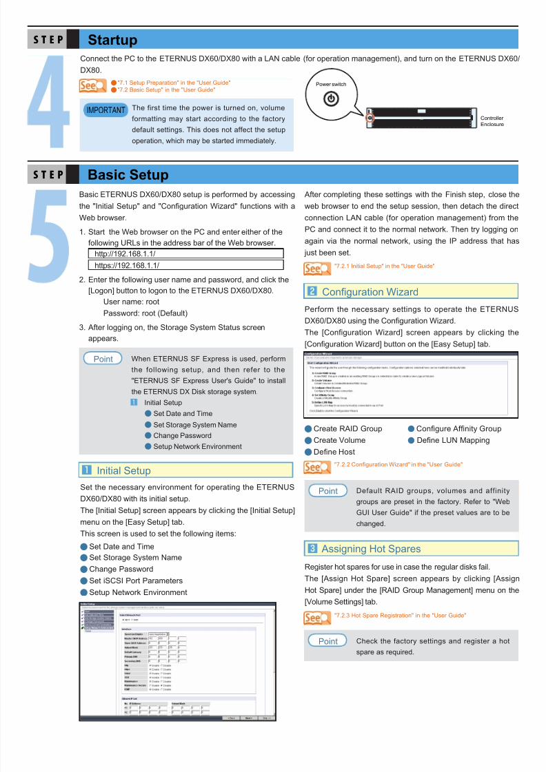
Set the necessary environment for operating the ETERNUSDX60/DX80 with its initial setup.The [Initial Setup] screen appears by clicking the [Initial Setup]menu on the [Easy Setup] tab.This screen is used to set the following items:
Set Date and TimeSet Storage System NameChange PasswordSet iSCSI Port ParametersSetup Network Environment
nn
nn
n
Initial Setup
StartupS T E P
Basic ETERNUS DX60/DX80 setup is performed by accessingthe "Initial Setup" and "Con guration Wizard" functions with aWeb browser.
Start the Web browser on the PC and enter either of thefollowing URLs in the address bar of the Web browser.
http://192.168.1.1/https://192.168.1.1/
Enter the following user name and password, and click the[Logon] button to logon to the ETERNUS DX60/DX80.
User name: rootPassword: root (Default)
After logging on, the Storage System Status screenappears.
1.
2.
3.
The first time the power is turned on, volume
formatting may start according to the factory
default settings. This does not affect the setup
operation, which may be started immediately.
IMPORTANT
Perform the necessary settings to operate the ETERNUSDX60/DX80 using the Con guration Wizard.The [Configuration Wizard] screen appears by clicking the[Con guration Wizard] button on the [Easy Setup] tab.
Register hot spares for use in case the regular disks fail.The [Assign Hot Spare] screen appears by clicking [AssignHot Spare] under the [RAID Group Management] menu on the[Volume Settings] tab.
Configuration Wizard
Assigning Hot Spares
Create RAID Group n Con gure Af nity GroupCreate Volume n De ne LUN MappingDe ne Host
n
nn
Check the factory settings and register a hot
spare as required.Point
Default RAID groups, volumes and affinity
groups are preset in the factory. Refer to "Web
GUI User Guide" if the preset values are to be
changed.
Point
"7.1 Setup Preparation" in the "User Guide""7.2 Basic Setup" in the "User Guide"
nn
After completing these settings with the Finish step, close theweb browser to end the setup session, then detach the directconnection LAN cable (for operation management) from thePC and connect it to the normal network. Then try logging onagain via the normal network, using the IP address that has
just been set.
"7.2.1 Initial Setup" in the "User Guide"
"7.2.2 Con guration Wizard" in the "User Guide"
"7.2.3 Hot Spare Registration" in the "User Guide"
Connect the PC to the ETERNUS DX60/DX80 with a LAN cable (for operation management), and turn on the ETERNUS DX60/DX80.
Controller Enclosure
Power switch
When ETERNUS SF Express is used, perform
the following setup, and then refer to the
"ETERNUS SF Express User's Guide" to install
the ETERNUS DX Disk storage system.
Initial SetupSet Date and Time
Set Storage System NameChange Password
Setup Network Environment
Point

7/21/2019 Dx Entry Setupguide Iscsi
http://slidepdf.com/reader/full/dx-entry-setupguide-iscsi 4/4
Monitoring SetupS T E P
Server ConnectionS T E P
Operation and MaintenanceS T E P
Remote support allows prompt detection and resolution of trouble.Point
Various tasks need to be performed before the ETERNUS DX60/DX80 can be connected to the server. These include theinstallation of the appropriate drivers and the setup of switching hub(s).Check which server OS, LAN cards, iSCSI HBAs, and/or switching hub(s) are to be connected to before starting this step.For details on the setting, refer to "ETERNUS DX Disk storage systems Server Connection Guide (iSCSI)"(*).* : Download from the speci ed web-site in the Documentation CD.
All necessary settings are complete, and the ETERNUS DX60/DX80 is now ready for normal operation.
This manual uses recycled paper.
ETERNUS DX60/DX80 Disk storage system Setup Guide(iSCSI model)
P3AM-3092-04ENDate of issuance: July 2010
Issuance responsibility: FUJITSU LIMITEDPrinted in Japan
The contents of this manual may be updated without notice. While the contents of this manual are the product of all due care anddiligence, no responsibility can be accepted for operational problemsarising from any errors or missing information, or other use of theinformation contained in this manual.
Fujitsu assumes no liability for damages to third party copyrights orother rights arising from the use of any information in this manual.
Contents of this manual are not to be reproduced without permissionfrom Fujitsu.
Manuals with missing or wrongly collated pages will be replaced free ofcharge.
Perform the ETERNUS DX60/DX80 monitoring setup if required.
Noti cation of ETERNUS DX60/DX80 problems as they occur is possible if the event noti cation method and level havebeen set.For e-mail noti cation of ETERNUS DX60/DX80 problems, a destination e-mail address must be set.If "ServerView" is used to monitor the server, the ETERNUS DX60/DX80 must be set to send an SNMP Trap to the server.If remote support is required, the ETERNUS DX60/DX80 must be set to notify the remote support center of failures.
n
nnn
"7.5 Server Connection Setup" in the "User Guide""ETERNUS DX Disk storage systems Server C onnection Guide (iSCSI)"for Solaris™ Operating System - for Linux (Red Hat Enterpris e Linux)for Windows ® - for Linux (SUSE Linux Enterpris e Server)for HP-UX - ETERNUS DX Disk Storage System Settings for ETERNUS DX60/DX80for VMware® ESX
nn
"7.4 Monitoring Setup" in the "User Guide"
Status check
Data backup
Maintenance support period
The status of the ETERNUS DX60/DX80 should be regularly monitored by checking the LEDs and using the Web browser.
Important data should be regularly backed up to a tape drive or similar device as a precaution against system failures.
The maintenance support period for the ETERNUS DX60/DX80 is 5 years from the date of purchase.