dyna-veyordyna-veyor.com/dveyor.pdf · dyna-veyor chain designs have been in the marketplace since...
TRANSCRIPT

DYNA-VEYOR
FORTY-THREE YEARS OF SERVICE AND DEPENDABILITY
800.326.5009WORLD HEADQUARTERS:
10 HUDSON STREET, NEWARK, NJ 07103PHONE: 973-484-1119 • FAX: 973-484-7790
E-mail: [email protected] Website: www.dyna-veyor.com

DYNA-VEYORFORTY-THREE YEARS OF SERVICE AND DEPENDABILITY
DYNA-VEYOR CUSTOM MOLDS ALL OF THEIR HIGH PRECISION THERMOPLASTIC COMPONENTS. DYNA-VEYOR CHAIN DESIGNS HAVE BEEN IN THE MARKETPLACE SINCE 1960. THERMOPLASTIC CONVEYOR COMPONENTS SERVE SAFE, QUIET CLEAN PRODUCT FOR CONTAINER CONVEYANCE FOR FOOD PROCESSING, BOTTLING, DISTILLING, PHARMACEUTICAL, DAIRY, FOOD SERVICE, ASSEMBLY, AND GENERAL INDUSTRIAL APPLICATIONS. THIS SELECTION OF A HIGH STRENGTH ENGINEERING THERMOPLASTIC RESIN (ACETAL) RESULTED IN LONG-LIFE CONVEYING CHAINS WITH OPERATION CAPABILITIES APPROACHING THOSE OF STAINLESS STEEL CHAINS. ACETAL HAS A HIGH TENSIL STRENGTH, FATIGUE ENDURANCE AND RIGIDITY AS WELL AS EXCEPTIONAL DIMENSIONAL STABILITY. ITS HIGH MOISTURE RESISTANCE ALLOWS FOR UTILIZATION IN WET ENVIRONMENTS WHERE THE WATER PRESENT SERVES AS AN EFFECTIVE LUBRICANT OR CLEANER. ACETAL IS NOTED FOR ITS LOW COEFFICIENT OF FRICTION AND EXCELLENT ABRASION RESIS-TANCE. CHEMICAL RESISTANCE OF ACETAL IS OUTSTANDING (FOR pH BETWEEN 2 & 10 PAGE 13). HIGH THERMAL RESISTANCE ALLOWS PERIODIC STEAM CLEANING (max 10 psi) AND INTERMITTENT OPERATION AT TEMPERATURES UP TO 185 DEG. F (SEE TEMPERATURE CHART PAGE 17) ACETAL HAS AN INTERNALLY LUBRICATED CHARACTERISTIC, WHICH ELIMINATES LUBRICATION IN MANY APPLICATIONS, THUS AVOIDING THE CONTAMINATION POTENTIAL. THIS CHARACTERISTIC ALSO REDUCES POWER AND WEAR REQUIREMENTS AND UNIT LOADING, EVEN WHEN RUNNING DRY. THE USE OF ACETAL ELIMINATES THE NOISY METAL ON METAL CONTACT OF STEEL CHAINS (AN IMPORTANT FACTOR WHEN OSHA COMPLIANCE IS A CONCERN). ALL CHAINS ARE AVAILABLE IN FDA AND USDA GRADES. THERMOPLASTIC RESIN WITH A LOW FRICTION ADDITIVE CREATES ADDITIONAL FEATURES. THE COEFFICIENT OF FRICTION IS LOWERED MORE, AND THE SLIPPING SURFACES OF THE LOW FRICTION ACETAL CHAIN SLIDE UNDER CONVEYED PRODUCTS WITHOUT SCORING OR SOILING CONTAINERS, RUBBING OFF COATINGS OR PLATINGS, OR DAMAGING SOFT ALUMINUM CANS. DYNA-VEYOR HAS TRAINED PEOPLE AVAILABLE TO ASSIST IN ANY CONVEYING PROBLEM. OUR REPS ARE LOCATED IN VARIOUS CITIES THROUGHOUT THE UNITED STATES. STANDARD PRODUCTS CAN BE SHIPPED IMMEDIATELY FROM FACTORY STOCKS AND CONVENIENTLY LOCATED WAREHOUSING REPS, OR FROM STOCKING POWER TRANSMISSION DISTRIBUTORS.
WE CANNOT ANTICIPATE ALL CONDITIONS UNDER WHICH INFORMATION AND OUR PRODUCTS, OR THE PRODUCTS OF OTHER MANUFACTURERS IN COMBINATION WITH OUR PRODUCTS, MAY BE USED. WE ACCEPT NO RESPONSIBILITY FOR RESULTS OBTAINED BY THE APPLICATION OF THIS INFORMATION OR THE SAFETY AND STABILITY OF OUR PRODUCTS, EITHER ALONE OR IN COMBINATION WITH OTHER PRODUCTS. USERS ARE ADVISED TO MAKE THEIR OWN TESTS TO DETERMINE THE SAFETY AND SUITABILITY OF EACH SUCH PRODUCT OR PRODUCT COMBINATION FOR THEIR OWN PURPOSES. UNLESS OTHERWISE AGREED IN WRITING, WE SELL THE PRODUCTS WITHOUT WARRANTY, AND BUYERS AND USERS ASSUME ALL RESPONSIBILITY AND LIABILITY FOR LOSS OR DAMAGE ARISING FROM THE HANDLING AND USE OF OUR PRODUCTS, WHETHER USED ALONE OR IN COMBINATION WITH OTHER PRODUCTS.
PART DIMENSIONS ARE SUBJECT TO CHANGE DUE TO MATERIAL SELECTION AND DESIGN IMPROVEMENTS.
SPECIAL NOTE: PLASTIC PIN CONSTRUCTION AVAILABLE IN ALL 1700 SERIES 1873 #60 / 63 BASE CHAIN IS SOLID ROLLER CONSTRUCTION CHEMICAL RESISTANT CHAINS ARE AVAILABLE IN ALL CHAIN SERIES pH 2 to 12 or pH 1 to 13 COLOR VARIATIONS MAY BE OCCASIONALLY DETECTED DUE TO RESIN TYPES
DuPont and Delrin are registered trademarks of the DuPont Company — E.I. du Pont de Nemours & Co. (Inc.)

TABLE OF CONTENTS
PAGE 2 820-821-831 STRAIGHT RUNNING CHAINS PAGE 3 MULTIFLEX & BI-DIRECTIONAL CHAINS PAGE 4 880 & 880 TAB / 879 & 879 TAB FLEX CHAINS PAGE 5 882 & 882 TAB FLEX CHAINS PAGE 6 1873 SIDE FLEXING CLIP ON CHAINS PAGE 7 1873 GRIPPER CHAIN SERIES PAGE 8 THERMOPLASTIC SPROCKETS PAGE 9 THERMOPLASTIC IDLERS PAGE 10 STEEL SPROCKETS PAGE 11 INTERLOCKING WEAR STRIPS PAGE 12 CURVED WEAR STRIPS PAGE 13 CHEMICAL RESISTANCE ACETAL CHAINS PAGE 14 ENGINEERING PROCEDURES TABLE 1 – CHAIN WEIGHT PER FOOT TABLE 5 – SERVICE FACTOR PAGE 15 SYMBOLS & FORMULAS TABLE 2B & TABLE 2C PAGE 16 FRICTION TABLE 3 – CHAIN TO WEAR STRIP TABLE 4 – CHAIN TO PRODUCT & PLATE TOP STRAIGHT RUN CHAIN CALCULATION FORMULAS PAGE 17 FLEX CHAIN CALCULATION FORMULAS TABLE 5 – SERVICE FACTOR TABLE 6 – RADIUS/CORNER FACTOR TABLE 7 – TEMPERATURE RANGE PAGE 18 HORSEPOWER CALCULATIONS TABLE 8 – WORKING LOAD LIMITS TABLE 9 – SPEED LIMIT FACTORS TABLE 10 – HORSEPOWER PAGE 19 MULTIFLEX CHAIN PULL FORMULAS PAGE 20 MULTIFLEX CHAIN PULL TABLES TABLE 1 – TURN FACTOR CTF TABLE 2 – LENGTH FACTOR CLF TABLE 3 – DISC NUMBER FACTOR CDN TABLE 4 – DISC SPACE FACTOR CDF TABLE 5 – LOAD FACTOR CMF TABLE 6 – SLOPE FACTOR FACTOR CSFPAGE 21 SPECIAL PROBLEM APPLICATION PAGE 22 VACUUM LINE CHAINS PAGE 23 HIGH FRICTION INSERT CHAINS PAGE 24 1873 GRIPPER PADS PAGE 25 INTERCHANGEABLE REPLACEMENT CHAINS
NOVEMBER 2006

STRAIGHT RUNNING CHAINS ALL CHAINS ARE OFFERED IN: FDA APPROVED GRADES OF GRAY ACETAL, WHITE ACETAL, LOW FRICTION (BROWN), LOW WEAR (WHITE) & CHEMICAL RESISTANCE (WHITE)
2
CHAIN DIMENSIONS – 820 & 831 TYPEDIMENSIONS IN INCHES — ALL DIMENSIONS NOMINAL
Chain No.Acetal(Gray)
Chain No.LF Acetal(Brown)
PlateWidth
A
LinkPerFoot
PinDiam.
B
ChainPitchC
PlateThickness
D
OverallHt.E
OverallBarrelWidth
F
Plate Bot.To
Chain Bot.G
GuideClearance
H
WeightPerFoot
DV-325–D820 DV-325–LF820 3-1/4 8 1/4 1-1/2 5/32 9/32 1-21/32 3/8 1-3/4 0.56 DV-400–D820 DV-400–LF820 4 8 1/4 1-1/2 5/32 9/32 1-21/32 3/8 1-3/4 0.64 DV-450–D820 DV-450–LF820 4-1/2 8 1/4 1-1/2 5/32 9/32 1-21/32 3/8 1-3/4 0.69 DV-600–D820 DV-600–LF820 6 8 1/4 1-1/2 5/32 9/32 1-21/32 3/8 1-3/4 0.84 DV-750–D820 DV-750–LF820 7-1/2 8 1/4 1-1/2 5/32 9/32 1-21/32 3/8 1-3/4 0.99
DV-325–D831 DV-325–LF831 3-1/4 8 1/4 1-1/2 3/16 9/32 1-21/32 11/32 1-3/4 0.61 DV-450–D831 DV-450–LF831 4-1/2 8 1/4 1-1/2 3/16 9/32 1-21/32 11/32 1-3/4 0.75 DV-600–D831 DV-600–LF831 6 8 1/4 1-1/2 3/16 9/32 1-21/32 11/32 1-3/4 0.87 DV-750–D831 DV-750–LF831 7-1/2 8 1/4 1-1/2 3/16 9/32 1-21/32 11/32 1-3/4 1.08
PINS MADE OF 303SS
CHAIN DIMENSIONS – 821 TYPE (DIRECT REPLACEMENT)DIMENSIONS IN INCHES — ALL DIMENSIONS NOMINAL
Chain No. Acetal*(Grey)
Chain No.LF Acetal(Brown)
PlateWidth
A
LinkPerFoot
PinDiam.
B
ChainPitchC
PlateThickness
D
OverallHt.E
OverallBarrelWidth
F
Plate Bot.To
Chain Bot.G
GuideClearance
H
WeightPerFoot
DV-750–D821 DV-750–LF821 7-1/2 8 1/4 1-1/2 3/16 5/16 5-3/8 3/8 5-1/2 1.70 DV-100–D821 DV-100–LF821 10 8 1/4 1-1/2 3/16 5/16 5-3/8 3/8 5-1/2 2.00 DV-120–D821 DV-120–LF821 12 8 1/4 1-1/2 3/16 5/16 5-3/8 3/8 5-1/2 2.20
PINS MADE OF 303SS

MULTIFLEX & BI-DIRECTIONAL CHAINS ALL CHAINS ARE OFFERED IN: FDA APPROVED GRADES OF GRAY ACETAL, WHITE ACETAL, LOW FRICTION (BROWN), LOW WEAR (WHITE) & CHEMICAL RESISTANCE (WHITE)
3
1700 SERIES LINK MATERIAL
PART NUMBER
Width Min. Radius
2-11/64" 5-1/2"
LFACETALSSPINS
WHITEACETALSSPINS
DV-1700LF DV-1700W
LINK MATERIAL
PART NUMBER
Width Min. Radius
2-3/32" 5-1/2"
LFACETALSSPINS
WHITEACETALSSPINS
DV-1701TAB-LF DV-1701TAB-W
1. DV-1702-LF(LFStraightSide)Bi-directional2. DV-1700-LF(LowFriction)3. DV-1701TAB-LF(LowFriction)Bi-directional4. DV-1701-LF(LFBevelSide)Bi-directional5. DV-1703TAB-LF(ExtendedPin)MTOBi-directional
• PROVIDES ADVANTAGES IN PRODUCT HANDLING.• DESIGN PROVIDES PRODUCT PROTECTION AND STABILITY• SMALL SIDEFLEX RADIUS PERMITS MORE EFFICIENT USE OF EXISTING
FLOOR SPACE• LOW WEAR MATERIAL PREVENTS RAPID BUILD-UP OF CHAIN TENSION• FDA/USDA APPROVED RESINS AND 303 SS PINS• PLASTIC PIN CONSTRUCTION AVAILABLE• 10 FT = APPROX. 61 LINKS
ALPINE CONVEYORS • CASE & CRATE HANDLING • PARTS HANDLING • CAN, BOTTLE & CARTON HANDLING
1701 TAB SERIES
CHAINPITCH 1.968"L HTOVERC/L 1/2"T THICKNESS 3/16" GC,STRA. 2-11/32" GC,TABRTN 2-1/4" GC,CURVE 2-1/4"TW TABWIDTH 2-5/8"H OVERALLHT 63/64"G CHAINT/TABT 3/4"E PINDIA 5/16" WT/FT,LB 1.0TT TABTHICKNESS 3/16'
CHAINPITCH 1.968"L HTOVERC/L 15/32"T THICKNESS 7/64" GUIDECL 2-9/32"G DIMENSION 15/32"H OVERALLHT 15/16"E PINDIA 5/16" WT/FT,LB .85

FLEX CHAINS ALL CHAINS ARE OFFERED IN: FDA APPROVED GRADES OF GRAY ACETAL, WHITE ACETAL, LOW FRICTION (BROWN), LOW WEAR (WHITE) & CHEMICAL RESISTANCE (WHITE)
4
TAB SERIES
*Food Industry Qualifications ThesechainsareincompliancewithcurrentFDAandUSDAregulationsgoverninguseofchainsindirectcontactwithfoodproducts.
CHAIN DIMENSIONS – 880 & 879 TYPEDIMENSIONS IN INCHES — ALL DIMENSIONS NOMINAL
Chain No. Acetal*(Grey)
Chain No.LF Acetal(Brown)
PlateWidth
A
LinkPerFoot
MinimumSide FlexRadius
B
ChainPitchC
PlateThickness
D
OverallHt.E
OverallBarrelWidth
F
Plate Bot.To
Chain Bot.G
GuideClearanceStraight
H
WeightPerFoot
DV-325–D880 DV-325–LF880 3-1/4 8 18 1-1/2 5/32 19/64 1-11/16 5/8 1-3/4 1-5/8 0.60 — — DV-450–D880 DV-450–LF880 4-1/2 8 24 1-1/2 5/32 19/64 1-11/16 5/8 1-3/4 1-5/8 0.70 — — DV-325–D880TAB DV-325–LF880TAB 3-1/4 8 18 1-1/2 5/32 19/64 1-11/16 5/8 1-13/16 1-3/4 0.63 2-13/32 15/32 DV-450–D880TAB DV-450–LF880TAB 4-1/2 8 24 1-1/2 5/32 19/64 1-11/16 5/8 1-13/16 1-3/4 0.74 2-13/32 15/32
DV-325–D879 DV-325–LF879 3-1/4 8 18 1-1/2 3/16 19/64 1-11/16 5/8 1-3/4 1-5/8 0.60 — — DV-450–D879 DV-450–LF879 4-1/2 8 24 1-1/2 3/16 19/64 1-11/16 5/8 1-3/4 1-5/8 0.70 — — DV-325–D879TAB DV-325–LF879TAB 3-1/4 8 18 1-1/2 316 19/64 1-11/16 5/8 1-13/16 1-3/4 0.63 2-13/32 15/32 DV-450–D879TAB DV-450–LF879TAB 4-1/2 8 24 1-1/2 3/16 19/64 1-11/16 5/8 1-13/16 1-3/4 0.74 2-13/32 15/32
PINS MADE OF 303SS
GuideClearance
CurvedH1
TabWidth
I
PlateBot. toTab Top
J
NON-TAB SERIES

FLEX CHAINS ALL CHAINS ARE OFFERED IN: FDA APPROVED GRADES OF GRAY ACETAL, WHITE ACETAL, LOW FRICTION (BROWN), LOW WEAR (WHITE) & CHEMICAL RESISTANCE (WHITE)
5
*Food Industry Qualifications ThesechainsareincompliancewithcurrentFDAandUSDAregulationsgoverninguseofchainsindirectcontactwithfoodproducts.
882 SERIES 882 TAB SERIES
CHAIN DIMENSIONS – 882 & 882 TAB TYPE (DIRECT REPLACEMENT)DIMENSIONS IN INCHES — ALL DIMENSIONS NOMINAL
Chain Number PlateWidth
K
LinkPerFoot
MinimumSide FlexRadius
H
ChainPitch
PlateThickness
T
OverallHeightC/L-L
L
PlateBottom
Barrel WidthQ
To ChainBottom
H
GuideClearanceStraight
GC
WeightPerFoot
DV-450–LF882 4-1/2 8 24 1-1/2 3/16 3/8 2-13/32 11/16 1.30 — — 2-7/16 2-9/32 11/32 DV-750–LF882 7-1/2 8 24 1-1/2 3/16 3/8 2-13/32 11/16 1.60 — — 2-7/16 2-9/32 11/32 DV-100–LF882 10 8 24 1-1/2 3/16 3/8 2-13/32 11/16 1.90 — — 2-7/16 2-9/32 11/32 DV-120–LF882 12 8 24 1-1/2 3/16 3/8 2-13/32 11/16 2.13 — — 2-7/16 2-9/32 11/32
DV-450–LF882TAB 4-1/2 8 24 1-1/2 3/16 3/8 2-1/4 7/8 1.33 3 11/16 2-3/8 2-9/32 11/32 DV-750–LF882TAB 7-1/2 8 24 1-1/2 3/16 3/8 2-1/4 7/8 1.63 3 11/16 2-3/8 2-9/32 11/32 DV-100–LF882TAB 10 8 24 1-1/2 3/16 3/8 2-1/4 7/8 1.90 3 11/16 2-3/8 2-9/32 11/32 DV-120–LF882TAB 12 8 24 1-1/2 3/16 3/8 2-1/4 7/8 2.13 3 11/16 2-3/8 2-9/32 11/32
PINS MADE OF 303SS
GuideClearance
CurvedGC
TabWidth
JPinE
PlateBottom toTab Top
G

LF 1873 TAB SIDE-FLEX CHAINS ALL CHAINS ARE OFFERED IN: FDA APPROVED GRADES OF GRAY ACETAL, WHITE ACETAL, LOW FRICTION (BROWN), LOW WEAR (WHITE) & CHEMICAL RESISTANCE (WHITE)
6
SIDE-FLEX SS BASE CHAIN
Chain Information ChainPitch
Width(Inches)
Width(Decimal) mm
Minimum Radius(Inches)
Minimum Radius(mm)
DV-1873–250TAB 3/4" 2-1/2" 2.5 57.2mm 14" 355.6mm DV-1873–325TAB 3/4" 3-1/4" 3.25 82.6mm 14" 355.6mm DV-1873–450TAB 3/4" 4-1/2" 4.5 114.3mm 14" 355.6mm DV-1873–600TAB 3/4" 6" 6.0 152.4mm 18" 457.2mm DV-1873–750TAB 3/4" 7-1/2" 7.5 190.5mm 18" 457.2mm DV-1873–100TAB 3/4" 10" 10.0 254.0mm 18" 457.2mm DV-1873–120TAB 3/4" 12" 12.0 304.8mm 24" 609.6mm
PREFIX MATERIAL TYPES
AS ANTI-STATICD ACETAL GRAYWD ACETAL WHITEFR FIRE RETARDANTHPB ADDED PERFORMANCE BROWNHPW ADDED PERFORMANCE WHITEHS HEAT RESISTANTLF LOW FRICTION BROWNWLF LOW FRICTION WHITEHR/MR HEAT/MELT RESISTANTP CHEMICAL RESISTANTSCR SUPER CHEMICAL RESISTANTUV ULTRAVIOLET RESISTANTCCR CC-REDPCB PC-BLUEFT FREEZER TUNNELVAC VACUUM HOLE CHAINSLW SUPER LOW WEAR
www.dyna-veyor.com • e-mail: [email protected]
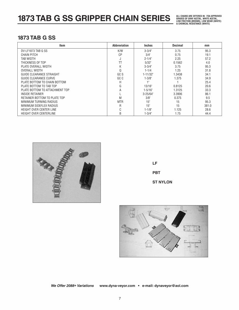
1873 TAB G SS GRIPPER CHAIN SERIES
7
1873 TAB G SSItem Abbreviation Inches Decimal mm
DV-LF1873TABGSS K/W 3-3/4" 3.75 95.3 CHAINPITCH CP 3/4" 0.75 19.1 TABWIDTH J 2-1/4" 2.25 57.2 THICKNESSOFTOP TT 5/32" 0.1562 4.0 PLATEOVERALLWIDTH K 3-3/4" 3.75 95.3 OVERALLWIDTH Q 1-1/4 1.25 31.8 GUIDECLEARANCESTRAIGHT GCS 1-11/32" 1.3438 34.1 GUIDECLEARANCECURVE GCC 1-3/8" 1.375 34.9 PLATEBOTTOMTOCHAINBOTTOM H 1" 1 25.4 PLATEBOTTOMTOTABTOP G 13/16" 0.8125 20.6 PLATEBOTTOMTOATTACHMENTTOP A 1-5/16" 1.3125 33.3 INSIDERETAINER L 3-25/64" 3.3906 86.1 RETAINERBOTTOMTOPLATETOP M 3/8" 0.375 9.5 MINIMUMTURNINGRADIUS MTR 15" 15 95.3 MINIMUMSIDEFLEXRADIUS R 15" 15 381.0 HEIGHTOVERCENTERLINE C 1-1/8" 1.125 28.6 HEIGHTOVERCENTERLINE B 1-3/4" 1.75 44.4
We Offer 2088+ Variations www.dyna-veyor.com • e-mail: [email protected]
ALL CHAINS ARE OFFERED IN: FDA APPROVED GRADES OF GRAY ACETAL, WHITE ACETAL, LOW FRICTION (BROWN), LOW WEAR (WHITE) & CHEMICAL RESISTANCE (WHITE)
LF
PBT
ST NYLON

THERMOPLASTIC SPROCKETS
8
Type Face L/T/B Hub Teeth
820 1.685 1.685 2.335 19212325 880 0.830 1.625 2.500 101112 882 0.885 1.875 2.500 101112 1700 0.430 1.575 3.500 81012
P820
U882U820
U821
U880
U1700
Sprocket Teeth OD Pitch Root
P820 P82019 19 4.610 4.620 4.095 P82021 21 5.120 5.089 4.564 P82023 23 5.590 5.560 5.035 P82025 25 6.070 6.032 5.507
IDLER DV21 19EQV 4.800 DV23 21EQV 5.110 DV25 23EQV 5.600 DV25 25EQV 6.890 P821 P82121 21 5.120 5.089 4.564 P82123 23 5.590 5.560 5.036 P82125 25 6.070 6.032 5.507
P880 P88010 10 4.820 4.854 4.234 P88011 11 5.310 5.324 4.704 P88012 12 5.800 5.796 5.178
P882 P88010 10 4.920 4.854 4.083 P88011 11 5.410 5.324 4.505 P88012 12 5.900 5.796 5.025
U1700 U17008 8 5.250 5.143 4.275 U170010 10 6.500 6.369 5.382 U170012 12 7.720 7.604 6.618
U820 U82019 19 4.610 4.620 4.095 U82021 21 5.120 5.089 4.564 U82023 23 5.590 5.560 5.035 U82025 25 6.070 6.032 5.507 U82027 27 6.560 6.504 5.979 U82029 29 7.050 6.978 6.453 U82031 31 7.530 7.452 6.927 U82041 41 9.930 9.826 9.301
U821 U82121 21 5.120 5.089 4.564 U82123 23 5.590 5.560 5.036 U82125 25 6.070 6.032 5.507
U880 U8809 9 4.333 4.386 3.766 U88010 10 4.820 4.854 4.234 U88011 11 5.310 5.324 4.704 U88012 12 5.800 5.796 5.178 U88015 15 7.260 7.215 6.595
U882 U8829 9 4.430 4.386 3.616 U88210 10 4.920 4.854 4.083 U88211 11 5.410 5.324 4.505 U88212 12 5.900 5.796 5.025

THERMOPLASTIC IDLERS
9
820
880 TAB 882 TAB
821
Split Design for Use With 820, 821, 880, 880 TAB, 882 and 882 TAB Designs
HEAVY DUTY • CHEMICAL RESISTANT
SPECIAL FEATURES
• Self Tracking• Fixed or Free Running• Rigid and Tough• Ultra-High Loading Capacity• Silent Running• No Lubrication• 90% Less Weight Than Steel• Clean and Hygienic• Maintenance Free• Resistant to Most Chemical
and Corrosive Conditions• For Steel and Plastic Chain• May be Keyed to Shaft or
Free-Wheel• Adjustable Face Width
(see below)
RECOMMENDED SET COLLAR CLEARANCE = 1/32"
Part No. No. of Teeth Stock Bore Pitch Diameter
LOW FRICTION ACETAL IDLERS
DV-19 19Equ. 3/4"&1" 4.620 DV-21 21Equ. 3/4"&1" 5.089 DV-23 23Equ. 3/4"&1" 5.560 DV-25 25Equ. 3/4"&1" 6.032
CHEMICAL RESISTANT IDLERS
DV-19-P 19Equ. 3/4"&1" 4.620 DV-21-P 21Equ. 3/4"&1" 5.089 DV-23-P 23Equ. 3/4"&1" 5.560 DV-25-P 25Equ. 3/4"&1" 6.032
Spacers Supplied for 821, 880 TAB, 882, 882 TABSee Price Sheet

STEEL SPROCKETS
10
S820
S821
S880
S882
Part No. No. of Teeth Stock Bore B Pitch Diameter
STEEL SPROCKETS*
S820-19 19 3/4" 4.620 820 S820-21 21 3/4" 5.089 820 S820-23 23 3/4" 5.560 820 S820-25 25 3/4" 6.032 820 S820-27 27 3/4" 6.504 820
S821-21 21 1" 5.089 821 S821-23 23 1" 5.560 821 S821-25 25 1" 6.032 821
S880-9 9 3/4" 4.386 880 S880-10 10 3/4" 4.854 880 S880-11 11 3/4" 5.324 880 S880-12 12 3/4" 5.796 880 S880-15 15 3/4" 7.215 880
S882-9 9 3/4" 4.386 882 S882-10 10 3/4" 4.854 882 S882-11 11 3/4" 5.324 882 S882-12 12 3/4" 5.796 882
For Chain Type
*OTHER SIZES AVAILABLE UPON REQUEST
Low Wear Acetal Sprockets Stock Shaft Bore = 3/4" & 1" (see page 8)Chemical Resistant Sprockets Stock Bore = 3/4" & 1" (see page 8)UHMW Sprockets Stock Bore = 3/4" & 1" (see page 8)

INTERLOCKING WEAR STRIPS
11
LOW FRICTION • LOW WEAR
Extends through the underside to rest on ways
3/16" tolerance to permit normal expansion and contraction
Conical hole 5/32" diameter at base. 3/8" diameter at top to receive round tapered head of screw
Physical and mechanical...
Tensile Strength 9 73˚F — 8800 PSIRockwell Hardness — M80Tensile Impact Strength 9 73˚F 70 ft. lb. per sq. in.Water Absorption 9 73˚F .22%Shear Strength — 7700 PSICoefficient of Friction — Less than .1
Chemical Properties...High resistance to strong alkalies and detergents.Approved by the National Sanitation Foundation for
use with potable water.
COEFFICIENTS OF FRICTIONDRY ................................................. .07WATER ............................................ .06SOAP & WATER .............................. .06
DIMENSIONS IN INCHES
Catalog No. OverallLength
of Strips
Center to Center
of Fasterner
Widthof
Strips
For ChainsWith Plate
WidthsStrip
Thickness
WS-015 16 15 3/4 3-1/4–4-1/2 3/16
The molded wear strips are made from acetal, which has a lubricating ingredient, this material possesses exceptional and desirable properties for conveyor chain wear strips. The configuration, size, thick-ness, and connecting joint characteristics have resulted in an advanced design for more efficient and economical conveyor chain operation.
DYNA-VEYOR WEAR STRIPS...
Contribute to pulsation free conveyorsEliminate pitted and dirty waysNo humpingEasily installedProvide clean conveyed items...cans, bottles, and boxesReduce friction extending life of chainUse less powerMinimize product breakageSanitaryQuiet operationEasily cleaned
OUTSTANDING MOUNTING DESIGN...
Dyna-Veyor Wear Strips have a positive mating method. The configuration of the joining ends produce a “locked” connection with a tolerance of 3/16" that permits normal expansion and contraction while in use. These are secured by stainless steel flat head machine screw 8-32˚ with hex head nut.
These fasteners always fit in their hole in a manner that allows no interference with the plate link of the chain. The top strip at the connecting joint is molded to extend through the under strip and rests on the way. The hole for the screw is conical in shape and accepts the tapered shape of the machine screw for a positive fit.
The 15" mounting centers of the DYNA-VEYOR strips require less holes per conveyor length. The top side of the strips have rounded edges for longer wear and smoother operation.

CURVED WEAR STRIPS (SOLID TRACKS & CURVES AVAILABLE ON REQUEST)
12
Line up corner strip and subsequent straight strip edges to ensure pulsation free operation.
GUIDECLEARANCESTRAIGHT
GUIDECLEARANCE
CURVE
1/16" to 1/8" GAP
MOUNTING
BEVEL RECTANGULAR
ALL DIMENSIONS NOMINAL
ONE-PIECE LINK CHAIN
BEVEL DESIGN WEAR STRIP
Chain Series TrackNumber
RADC/LA
TrackInside
D
RadiusOutside
E
BoltIB
CircleOC
WidthW
Thickness*T
GuideClearance
Straight Curved.
880N/T&881N/T U18B3 A=18 17-3/16 18-13/16 16-11/16 19-5/16 1.000 3/8 1-3/4 1-5/8 U24B3 A=24 23-3/16 24-13/16 22-11/16 25-5/16 1.000 3/8 1-3/4 1-5/8 U30B3 A=30 29-3/16 30-13/16 28-7/16 31-9/16 1.500 3/8 1-3/4 1-5/8
RECTANGULAR DESIGN WEAR STRIP
880TAB&881TAB U18R3 A=18 17-1/8 18-7/8 16-1/4 19-3/4 1.500 3/8 1-13/16 1-3/4 U24R3 A=24 23-1/8 24-7/8 22-1/4 25-3/4 1.500 3/8 1-13/16 1-3/4 U30R3 A=30 29-1/8 30-7/8 28-1/4 31-3/4 1.500 3/8 1-13/16 1-3/4
BEVEL DESIGN WEAR STRIP
882N/T U24B5 A=24 22-55/64 25-9/64 21-63/64 26-1/64 1.500 5/8 2-7/16 2-9/32 U30B5 A=30 28-55/64 31-9/64 27-63/64 32-1/64 1.500 5/8 2-7/16 2-9/32
RECTANGULAR DESIGN WEAR STRIP
882TAB U24R5 A=24 22-55/64 25-9/64 21-63/64 26-1/64 1.500 5/8 2-3/8 2-9/32 U30R5 A=30 28-55/64 31-9/64 27-63/64 32-1/64 1.500 5/8 2-3/8 2-9/32
BEVEL DESIGN WEAR STRIP
1701N/TBEVEL U24B5 A=24 22-29/32 25-3/32 22-1/32 25-31/32 1.500 3/4 2-11/32 2-3/16 U30B5 A=30 28-29/32 31-3/32 28-1/32 21-31/32 1.500 5/8 2-11/32 2-3/16
RECTANGULAR DESIGN WEAR STRIP
1701TAB U24R5 A=24 22-7/8 25-1/8 22 26 1.500 5/8 2-11/32 2-1/4 RECTANGULAR U30R5 A=30 28-7/8 31-1/8 28 32 1.500 5/8 2-11/32 2-1/4
*THICKNESSTOLERANCE=0-1/16" GUIDECLEARANCE=±1/64"

CHEMICAL RESISTANCE — ACETAL CHAINS
13
PARTIAL LISTING For Higher Chemical Resistance Contact DYNA-VEYOR
TABLE A TimeMaterial Month Vis. Obs.
Control (Air) 12 N.C.
INORGANIC CHEMICALS10% Ammonium Hydroxide 6 Disc. 12 Disc. 6 Disc.3% Hydrogen Peroxide 6 N.C. 12 N.C.10% Hydrochloric Acid 610% Nitric Acid 610% Sodium Chloride 6 N.C. 12 SI. Disc. 6 SI. Disc.2% Sodium Carbonate 6 N.C. 12 N.C.20% Sodium Carbonate 6 N.C.1% Sodium Hydroxide 6 N.C. 12 N.C.10% Sodium Hydroxide 6 N.C. 12 N.C. 6 SI. Disc.60% Sodium Hydroxide 6 SI. Disc.4.6% Sodium Hypochlorite 6 Pitted26% Sodium Thiosulfate 6 N.C.3% Sulfuric Acid 6 N.C. 12 N.C.30% Sulfuric Acid 6Buffer, pH 7.0 6 SI. Disc.Buffer, pH 10.0 6 SI. Disc.Buffer, pH 4.0 4Water (Distilled) 6 N.C. 12 N.C. 12 Disc.
ORGANIC CHEMICALS5% Acetic Acid 6 N.C. 12 N.C.Acetone 6 N.C. 12 N.C. 6 N.C.Aniline 6 Reddish TintBenzene 6 N.C.Carbon Tetrachloride 6 N.C. 12 N.C. 6 N.C.10% Citric Acid 6 N.C. 12 N.C.Diethyl Ether 6 N.C.Dimethyl Formamide 6 N.C.Ethyl Acetate 6 N.C.Ethylene Dichloride 6 N.C.50% Ethylene Glycol 6 SI. Disc.95% Ethanol 6 N.C. 12 N.C. 6 N.C.
TimeMaterial Month Vis. Obs.
50% Ethanol 6 N.C. 12 N.C. 6 N.C.Heptane 6 N.C. 12 N.C. 6 N.C.Oleic Acid 6 N.C. 12 N.C. 6 N.C.6% Phenol 6 N.C. 12 Disc.Toluene 6 N.C. 12 N.C. N.C.OTHER MATERIALSAutomatic Transmission Fluid 6 N.C.Anti-Freeze (Telar) 6 N.C.Brake Fluid, “Super 9” 6 N.C. 12 N.C.Brake Fluid, “Lockheed 21” 6 N.C. 12 N.C. 6 N.C.Brake Fluid, “Delco 222” 6 N.C.Detergents “Acclaim” 6 SI. Disc. “Calgonite” 6 SI. Disc. “Electro-Sol” 6 N.C. 50% Igepal 6 N.C. 12 N.C. 6 N.C.Detergent Solution 6 SI. Disc.1% Soap Solution 6 N.C.Gasolines Mobil Regular (93.5 Octane) 6 N.C. Mobil “Hi-Test” (99.0 Octane) 6 N.C. Sunoco “280” (103 Octane) 6 N.C.Kerosene 6 N.C.Linseed Oil 6 N.C.Lubricating Grease 6 N.C.Mineral Oil (“Nujol”) 6 N.C. 12 N.C. 6 N.C.Motor Oil (10W30) 6 N.C. 12 N.C. 6 N.C.
SPECIAL NOTE: With thermoplastics do not use cleaning or lubricating agents with a pH below 4 or above 10 or chemicals containing free chlorine or free ammonia. These agents may cause immediate attack or “crazing” after several applications due to concentration by evaporation.
*CONTACT FACTORY FOR MORE INFORMATION
NOTES: X = Not Recommended; NC = No Change; Disc. = Discoloration; SI. Disc. = Slight Discoloration

4. Determine friction factor betwen chain type and wear strip material.
(Refer to Table 3)
5. Determine friction factor betwen chain type and chain material.
(Refer to Table 4)
6. Determine plate top width, additional number of strands when applicable and conveyor speed.
(Refer to Step 1 above and Tables 2B & 2C)
7. Calculate product weight per foot of chain using charts. (Refer to Table 2A) or,
8. Calculate conveyor weight per foot of conveyor. (Refer to Table 1 for chain weight) ( Refer to Step 6 above for product weight)
9. Determine conveyor service factor using service factor table.
(Refer to Table 5)
ENGINEERING PROCEDURES
14
PROCEDURES:
1. Determine needed conveyor speed and chain width required for necessary product flow.
(Refer to Table 2A)
2. Select plate top and chain type using product material, abrasion, lubrication, chemical resistance and temperature range conditions as guides.
(Refer to Table 7 – Temperature Range, page 17) (Refer to Page 13 – Chemical Resistance) (Refer to Page 21 – Special Application Chains)
3. Select wear strip material using plate top material, lubrication types, chain loading and abrasion as considerations.
A. LW90 – special formulated for aluminum and steel can handling.
B. Stainless steel should be hard cold finished to 32-63 RMS with hardness of 25-30 RC.
C. Plastic polymer strips and corner tracks may deflect in high load conditions and should be avoided in such applications.
PRODUCTSPERMINUTE =REQUIREDCONVEYORSPEEDPRODUCTSPERFOOTOFCHAIN
(A)
166.277CONTAINERSPERSQ./FT.= D2
(B)
NO LUBRICATION LUBRICATEDWEAR STRIP No Abrasion Abrasion No Abrasion Abrasion
STAINLESSSTEEL G G G GLW90 G S G GUHMW S — S —NYLON G — G —
(C)
PRODUCTWT.PERFT.=PRODUCTSPERFT.xWT.PERPRODUCT
(D)
PRODUCTWT.PERFT.+CHAINWT.PERFT.=CONVEYORWEIGHTPERFOOT
(E)
TYPE 2 2-1/4 2-5/8 3-1/4 4 4-1/2 6 7-1/2 10 12
815 — 1.45 1.60 1.85 2.15 2.35 2.95 3.55 — —820 — — — 0.56 0.65 0.70 0.85 1.00 — —821 — — — — — — — 1.70 2.20 2.20831 — — — 0.60 — 0.75 — 1.10 — —843 0.60 — — 0.70 — — — — — —864 — — — 2.25 — 2.70 3.60 3.85 — —866 — — — 2.10 — 2.55 3.20 3.65 — —863 — — — 1.40 — 1.50 1.70 1.80 — —
880 — — — 0.80 — 0.70 — — — —880T — — — 0.65 — 0.75 — — — —881 — — — 2.00 — 2.50 — 3.70 — —881T — — — 2.00 — 2.50 — 3.70 — —882 — — — — — 1.30 — 1.60 1.90 —882T — — — — — 1.35 — 1.65 1.95 2.15
1700 — 0.85 — — — — — — — —1701 — 1.00 — — — — — — — —
TABLE 1 – CHAIN WEIGHT PER FOOT OF CHAIN
SLIPPAGE PERCENT DURING OPERATING/RUN TIMESTART/STOP None 0/10 10/50 50/100
NONE 1.0 1.3 1.6 1.9INFREQUENT 1.5 1.7 2.0 2.3FREQUENT 2.2 2.3 2.4 2.6
TABLE 5 – SERVICE FACTOR SF (F)

SYMBOLS & FORMULAS
15
TABLE 2BProducts Conveyed Per Foot of Chain
TABLE 2CProducts Per Minute / Per Foot Speed
SYMBOLS & FORMULAS:
1 PRODUCTSPERMINUTE =CONVEYORSPEEDPRODUCTPERFOOT
2 144SQ.IN. =PRODUCTSPERSQUAREFOOT 2
D=DIAMETEROFPRODUCT
3 GUIDERAILSPACE RS=[(NO.OFROWS•1)x(.886D)]+D .886(0)CIRCLEINSSQUARE
4 STRAIGHTRUN [(M+2W)xFWxL+(MxFMxL)]xSERVICEFACTOR
5 STRAIGHTRUNWITHINCLINE [(M+2W)xFWxH+(MxV)]xSERVICEFACTOR
6 CONVENTIONAL1700/1701WITHOUTSLIPPAGE [(M+2W)xFWxL]xSERVICEFACTOR
7 CONVENTIONAL1700/1701SLIPPAGE [(M+2W)xFWxL+(MxFMxLs)]xSERVICEFACTOR
*Forstartingfrictionunderload,add.15torunning(FW&FM)
8 FRICTIONFACTORS Fm=RUNNINGFRICTIONCHAINTOPRODUCT Fw =RUNNINGFRICTIONCHAINTOWEARSTRIP V =VERTICALRISE H =HORIZONTALLENGTH
9 SLOPE=RISEPERFOOT –OR–
SLOPE= 12xRISE
HORIZONTALLENGTH
SLOPEFACTOR=
SLOPEPERFOOT 12
CHAINULTIMATESTRENGTH
10 FS(FACTOROFSAFEY)= CHAINWORKINGLOAD
CHAINPITCHxNUMBEROFTEETHxRPM
11 CHAINSPEED= CHAINWORKINGLOAD
12xFPM
12 SPROCKETSPEED= NUMBEROFTEETHxPITCH

FRICTION
16
WEAR STRIP FRICTION TABLES:
WEAR STRIP MATERIAL Stainless CarbonPlate Top Type Condition Steel Steel UHMW Nylon
CARBON& Dry .50 .50 .40 .40STAINLESSSTEEL Water .40 .40* .30 .30 Soap&Water .30 .20* .20 .20 Oil .20 .20 .20 .20
ACETAL Dry .40 .40 .35 .35 Water .30 .30* .25 .25 Soap&Water .20 .20* .15 .15
LOWFRICTION Dry .25 .25 .20 .20 Water .20 .20* .20 .20 Soap&Water .15 .15* .15 .15
LOWWEAR+ Dry .07 .07 L/R L/R Water .06 .06 .06 .06 Soap&Water .06 .06+ .06 .06
TABLE 3 – FRICTION FACTORS F/W
*=Notrecommended+=Substantiallyreduceoreliminatesoaplubrication+=SpeciallyformulatedforaluminumcanhandlingsystemsL/R=Limited
PRODUCT & PLATE TOP FRICTION TABLES:
TOP PLATE MATERIAL Running Friction Coefficients Stainless CarbonPlate Material Condition Steel Steel* Acetal Nylon
PLASTIC Dry .40 .40 .30 .30PAPER* Water .30 .30 .20 .20FIBER Soap&Water .20 .20 .10 .10
METAL Dry .50 .50 .40 .40 Water .40 .40 .30 .30 Soap&Water .20 .20 .20 .20 Oil .20 .20 .20 .20
GLASS Dry .50 .50 .40 .40 Water .45 .45 .30 .30 Soap&Water .25 .25 .20 .20 Oil .20 .20 .20 .20
INDUSTRIAL Dry .50 .50 .40 .40PARTS Water .45 .45 .30 .30 Soap&Water .25 .25 .20 .20 Oil .20 .20 .20 .20
TABLE 4 – FRICTION FACTORS F/M
*=Waterandsoap/waterlubricationnotrecommendedL/R=Limited
CALCULATION OF STRAIGHT CHAIN PULL:
CHAIN PULL
PULL DUE TO PRODUCT SLIPPAGE
PULL FOR RETURN STRAND
P=[L(W+M)FW+P1+P2]SF
P2=WxFWxL
P1=WxFMxL
P CHAIN PULL
L CONVEYOR LENGTH (SPROCKET CENTER TO CENTER DISTANCE IN FEET)
W CHAIN WEIGHT PER FOOT (TABLE 1)
M WEIGHT OF PRODUCT x NUMBER OF PRODUCTS PER FOOT OF CHAIN (REFER TO TABLES 2A, 2B, & 2C)
FW FRICTION FACTOR BETWEEN PLATE TOP AND WEARING SURFACE (TABLE 3)
FM FRICTION FACTOR BETWEEN CHAIN TOP AND PRODUCT SURFACE (TABLE 4)
SF SERVICE FACTOR (TABLE 5)
P1 0 (WITH NO PRODUCT SLIPPAGE)
P1 M x FM x L
P2 ADDITIONAL PULL DUE TO CHAIN RETURN LENGTH W x FW x L
AFTER COMPLETION OF CHAIN PULL CALCULATION, PROCEED TO CHAIN SELECTION STEPS AND CHAIN LIMIT GRAPH.
CHAIN SELECTION STEPS
1. Locate on vertical axis chain pull “P” calculated.
2. Locate on horizontal axis appropriate speed/length ratio.
3. Draw straight lines on Graph No. 1 (see page 18): a) One line parallel to vertical axis at speed/length value. b) One line parallel to horizontal axis at chain pull value.
4. Intersect point of Step 3(a) and (b) lines provides a value that must be evaluated against chain capacity lines on graph. The chain capacity line above the intersect point of lines 3(a) and (b) indicates the proper chain for normal applications.
Refer to Chain Limits Graph 1 on Page 18.

FLEX CHAIN CALCULATION FORMULAS
17
CALCULATION OF SIDE FLEXING CHAIN PULL:
To evaluate the chain pull for side flexing chain applications, each component or chain section is found independently, and then summed to arrive at the pounds of pull which the chain must be able to withstand. In the figure below, calculate the chain pull for Section 1, Section 2, and Section 3. Add the results of the three sections.
FORMULA
SECTION PULL
PULL DUE TO PRODUCT SLIPPAGE
PULL FOR RETURN STRAND
P=[L(W+M)FW+P1+P2]RFxSF
P2=WxFWxL
P1=MxFMxL
P=P1+P2+P3+P4
Formula P = Psec 1 + Psec 2 + Psec 3
CALCULATION PROCEDURE:
1. To evaluate chain pull for Section 1, use:
A. Section 1 is the initial straight section. B. Values for P1 are found in Tables 1-5.
2. To evaluate chain pull for Section 2, use:
A. Section 2 is the curved section following Section 1. B. The RF/Radius Factor is located in Table 6. C. Length through turns are found using factors located
in Table 6.
3. To evaluate chain pull for Section 3, use:
A. Section 3 is the straight section between curved section and the drive sprocket.
B. The RF/Radius Factor should again be taken from Table 6.
When calculating additional curve and straight sections, apply the appropriate RF/Radius Factors to all additional sections.
Psec1=[L(W+M)FW+P1+P2]SF
Psec2=[L(W+M)FW+P1+P2]xRFxSF
Psec3=[L(W+M)FW+P1+P2]xRFxSF
CURVE ACETAL CHAINS STEEL CHAINS LENGTH THROUGH RADIUS Degree No Lube Lube No Lube Lube Length
30 1.20 1.10 1.20 1.10 .50xR=K 60 1.40 1.15 1.50 1.25 1.00xR=K 90 1.60 1.20 1.80 1.40 1.50xR=K 120 1.90 1.30 2.20 1.60 2.00xR=K 145 2.20 1.40 2.70 1.80 2.50xR=K 180 2.50 1.60 3.00 2.00 3.00xR=K
K=Lengththroughcorner
TABLE 6 – RADIUS/CORNER FACTORS
MINIMUM MAXIMUM TEMPERATURE TEMPERATUREMaterial Dry or Wet Dry Wet
ACETAL –40 185 160PBT/HT –10 325 140NYLON –40 170 150STAINLESS –100 800 800STEEL –40 350 350WOOD –50 160 160LW –40 185 160SLW –40 185 160POLYPROPYLENE 34 220 190POLYETHYLENE –50 150 120
TABLE 7 – TEMPERATURE GUIDE IN DEGREES F.
SLIPPAGE PERCENT DURING OPERATING/RUN TIMESTART/STOP None 0/10 10/50 50/100
NONE 1.0 1.3 1.6 1.9INFREQUENT 1.5 1.7 2.0 2.3FREQUENT 2.2 2.3 2.4 2.6
TABLE 5 – SERVICE FACTOR SF

HORSEPOWER CALCULATIONS
18
CHAIN TENSION x CHAIN SPEEDREQUIRED HP = x SERVICE FACTOR
33,000
For allowable conveyor speed limits — Apply factor Table 9.
For required horsepower — Look up Table 10.
The following formula determines the theoretical horsepower based on calculated chain pull. Therefore, proper service factors are to be applied to overcome prime mover startup and frictional losses.
HP HORSEPOWER — Look up Table 10
SF SERVICE FACTOR — Look up Table 5
FPM FEET PER MINUTE — Look up Graph 1
CT CHAIN PULL
HP = CT x FPM x SF 33000
CHAIN WORKING LOAD SERIES LIMIT
815 615 820 375 821 630 831 360 843 770 879 360 880 360 881 770 882 425 1700 600 1701 600 1873 630 SBR 1500
*StandardSeriesNOTE:PBTandPolyethylenechemicalresistantchainsworkingloadlimitsforchemicalresistantchainsaretwo-thirdsofthoselimitslistedforstandardseriesacetalchains.
TABLE 8 – WORKING LOAD LIMITS
FPM SLF
0... 50 1.0 50...100 1.2 100...165 1.4 165...230 1.6 230...300 2.2 300...360 2.8 360...400 3.2 400...460 +
(PxSLF=AdjustedWorkingLoad)
TABLE 9 – SPEED LIMIT FACTORS
GRAPH 1 — THERMOPLASTIC CHAIN LIMITS
After completion of chain pull calculation, multiply chain pull by the speed limit factor for desired speed.
The total factored chain pull value can then be compared to Table 8 Working Load Chain Limits for suitability instead of, or as a check of, the speed/length ratio limit. A value less than the working load limit of the chain series selected indicates relative permissable use.
FEET PER MINUTE SPEEDTENSION I 10 25 50 100 150 200 250 300
25 .01 .02 0.04 0.08 0.11 0.15 0.19 0.2350 .02 .04 0.08 0.15 0.23 0.30 0.38 0.4570 .02 .06 0.11 0.23 0.34 0.45 0.57 0.68100 .03 .08 0.15 0.30 0.45 0.61 0.76 0.91
150 .05 .11 0.23 0.45 0.68 0.91 1.14 1.36200 .06 .15 0.30 0.61 0.91 1.21 1.52 1.82250 .08 .19 0.38 0.76 1.14 1.52 1.89 2.27300 .09 .23 0.45 0.91 1.36 1.82 2.27 2.73
350 .11 .27 0.53 1.06 1.59 2.12 2.65 3.18400 .12 .30 0.61 1.21 1.82 2.42 3.03 3.64450 .14 .34 0.68 1.36 2.05 2.73 3.41 4.09500 .15 .38 0.76 1.52 2.27 3.03 3.79 4.55
550 .17 .42 0.83 1.67 2.50 3.33 4.17 5.00600 .18 .45 0.91 1.82 2.73 3.64 4.55 5.45650 .20 .49 0.98 1.97 2.95 3.94 4.92 5.91700 .21 .53 1.06 2.12 3.18 4.24 5.30 6.36
750 .23 .57 1.14 2.27 3.41 4.55 5.68 6.82800 .24 .61 1.21 2.42 3.64 4.85 6.06 7.27
Chain tension calculations must be adjusted or factored by the appropriate service factor or factors when applicable. The adjusted chain pull or working load should not exceed recommended chain working loads as per Table 8.
Drive requirements may then be selected from standard horsepower selection tables.
TABLE 10 – HORSEPOWER

19
MULTIFLEX CHAIN PULL FORMULAS
CALCULATION OF MULTIFLEX SIDE FLEXING CHAIN PULL:
To evaluate the chain pull for multiflexing chains in standard conveyor applications, each component or conveyor section is calculated independently, and the sections summed to arrive at the pounds of pull which the chain must be able to withstand. In the figure below, calculate the chain pull for Section 1, Section 2, and Section 3. Add the results of the three sections.
FORMULA
SECTION PULL
PULL DUE TO PRODUCT SLIPPAGE
PULL FOR RETURN STRAND
P=[L(W+M)FW+P1+P2]xRFxSF
P2=WxFWxL
P1=MxFMxL
P=P1+P2+P3+P4
CONFIGURATIONS WITHOUT CORNER DISCS:
1. To evaluate chain pull for Section 1, use:
A. Section 1 is the initial straight section. B. Values for P1 are found in Tables 1-5.
2. To evaluate chain pull for Section 2, use:
A. Section 2 is the curved section following Section 1. B. The RF/Radius Factor is located in Table 6. C. Length through turns are found using factors located
in Table 6.
3. To evaluate chain pull for Section 3, use:
A. Section 3 is the straight section between curved section and the drive sprocket.
B. The RF/Radius Factor should again be taken from Table 6.
When calculating additional curve and straight sections, apply the appropriate RF/Radius Factors to all additional sections.
Psec1=[L(W+M)FW+P1+P2]SF
Psec2=[L(W+M)FW+P1+P2]xRFxSF
Psec3=[L(W+M)FW+P1+P2]xRFxSF
CALCULATION PROCEDURE:
For configurations without corner discs.For configurations with corner discs.For configurations with multiple levels.
CONVENTIONAL CONFIGURATIONS WITH CORNER DISCS:
P=CLFxCTFx(2W+M)m
–or–
LengthFactorxTurnFactorx(2xChainWt.PerFt.+ProductWt.PerFt.)
CONFIGURATIONS WITH MULTIPLE LEVELS ELEVATING OR LOWERING:
P=CDNxCDFxCLFxCSFm
–or–
NumberofDiscsFactorxSpacingFactorxLoadFactorxSlopeFactor
P CHAIN PULL
L CONVEYOR LENGTH (SPROCKET CENTER TO CENTER DISTANCE IN FEET)
W 1700 = 0.85 LBS. (TABLE 1) 1701 = 1.00 LBS. (TABLE 1)
M WEIGHT OF PRODUCT x NUMBER OF PRODUCTS PER FOOT OF CHAIN (REFER TO TABLES 2A, 2B, & 2C)
FW FRICTION FACTOR BETWEEN PLATE TOP AND WEARING SURFACE (TABLE 3)
FM FRICTION FACTOR BETWEEN CHAIN TOP AND PRODUCT SURFACE (TABLE 4)
SF SERVICE FACTOR (TABLE 5)
P1 0 (WITH NO PRODUCT SLIPPAGE)
P1 M x FM x L
P2 ADDITIONAL PULL DUE TO CHAIN RETURN LENGTH W x FW x L
RF TURN/RADIUS FACTOR (TABLE 6, PAGE 17)
CTF CONVEYOR TURN FACTOR (CTF / TABLE 1)
CLF CONVEYOR LENGTH FACTOR (CLF / TABLE 2)
CDN NUMBER OF DISCS FACTOR (CDN / TABLE 3)
CDF CONVEYOR DISC FACTOR (CDF / TABLE 4)
CMF CONVEYOR LOAD FACTOR (CMF / TABLE 5)
CSF CONVEYOR SLOPE FACTOR (CSF / TABLE 6)
AFTER COMPLETION OF CHAIN PULL CALCULATION, PROCEED TO CHAIN SELECTION STEPS AND CHAIN SPEED/LENGTH RATIO LIMITS (GRAPH 1).
CHAIN SELECTION STEPS
1. Locate on vertical axis chain pull “P” calculated.
2. Locate on horizontal axis appropriate speed/length ratio.
3. Draw straight lines on Graph No. 1 (see page 18): a) One line parallel to vertical axis at speed/length value. b) One line parallel to horizontal axis at chain pull value.
4. Intersect point of Step 3(a) and (b) lines provides a value that must be evaluated against chain capacity lines on graph. The chain capacity line above the intersect point of lines 3(a) and (b) indicates the proper chain for normal applications.
When headshaft chain tension is greater than allowable chain working load, break the conveyor system into shorter sections and recalculate chain loads for each section.

20
MULTIFLEX CHAIN PULL TABLES
Number of Turns Factor
0 1.0 1 1.1 2 1.2 3 1.3
CTF – TURN FACTOR TABLE 1
CLF LENGTHOFCONVEYORFOOTAGEFACTOR [LF]
CDF DISTANCEBETWEENDISCS [D]
CRF TURN/RADIUS/CORNERFACTOR [R]
CDN NUMBEROFDISCSINTHECONVEYOR [N]
CSF RISEORSLOPEOFINCLINEINDEGREES [S]
CMF PRODUCTPOUNDSPERFOOTOFCONVEYOR [M]
CTF CORNERLOADFACTORFORCONVEYORSWITHOUTDISCS [T]
CPS PRODUCTSLIPPAGE/PEAKLOADINGFACTOR [P] FORSLIPPAGEANDSTOP-STARTPEAKLOADING WHENOCCURRING
See page 17 for useful symbols and formulas.
MULTIFLEX FACTOR TABLES
Length Feet Factor
0 0 20 5 40 10 60 15 80 20 100 25 120 30 140 35 160 40 180 45 200 50
CLF – LENGTH FACTOR TABLE 2
Number of Discs Factor
1 10 2 15 3 20 4 25 5 30 6 40 7 50 8 60 9 70 10 80 11 90 12 100 13 115 14 130 15 145 16 160
CDN – DISC NUMBER FACTOR TABLE 3
Disc Space Feet Factor
5 0.25 10 1.00 15 1.25 20 1.75
CDF – DISC SPACE FACTOR TABLE 4
Load Factor
1 1.5 2 2.5 3 3.0 4 3.5 5 4.0 6 4.5 7 5.0 8 5.5 9 6.0 10 6.5 11 7.0 12 7.5 13 8.0 14 8.5 15 9.0
CMF – LOAD FACTOR TABLE 5
Up Down Degrees Factor Factor
1 1.10 .90 2 1.15 .85 3 1.20 .80 4 1.25 .75 5 1.35 .65 6 1.45 .55
CSF – SLOPE FACTOR TABLE 6
Without Corner Discs
Conventional
P = CDN x CDF x CLF x CSF
MULTI LEVEL — 7 DISC SYSTEM

SPECIAL PROBLEM APPLICATIONS
21
NEW OFFERINGS FOR PROBLEM SOLVING AND FINE TUNING OF CONTAINER HANDLING AND PACKAGING
1. CHEMICAL RESISTANT — For problem applications in the 2-12 pH range.
2. ANTI-MAGNETIC — All plastic (link & pin) construction suited for metal detection equipment.
3. ANTI-STATIC — Material available which will eliminate electrical charge build-up. A must for electronics industry and some metal detection.
4. ELECTRICALLY CONDUCTIVE — For elimination of any static build-up.
5. FLAME RETARDANT — For any open flame application.
6. WEAR RESISTANT NYLON
7. HEAT/MELT RESISTANT — For baking or part processing hot parts.
8. HIGH IMPACT — For situations where product conveyed tends to “DROP” onto line.
9. HIGH PERFORMANCE — Lowest coefficient of friction material, increases wear life, reduces wear elongation, reduces backline pressure and more energy efficient.
10. HIGH FRICTION CHAIN — For applications that need a higher coefficient of friction.
11. HIGH FRICTION INSERT CHAIN — With inserts, attachments or a molded product for packaging problem applications. Insertion to increase friction, for example, on incline applications.
12. HIGH TEMPERATURE — Up to 350˚F plus.
13. HEAT STABILIZED — Resists thermal degradation from hot water sprays. For example, in rinsers and pasteurizers.
14. IRRADIATION CHAIN — For use in food sterilization processing. Used for years in Europe to retard spoilage, soon to be accepted in USA. To prevent bacteria growth, and extend food shelf life.
15. CHEMICAL & IMPACT RESISTANT
16. LOW TEMPERATURE — For freezer tunnels, to –40˚F.
17. LOW WEAR OR WEAR RESISTANT — Outlasts LF applications 5:1, for metal and aluminum can handling, high speeds, low loads, plastic to metal.
18. ALL PLASTIC CONSTRUCTION — Links and pins of plastic for reduction in HP requirements for all existing applications.
19. SUPER CHEMICAL RESISTANT — For extended range chemical resistance.
20. SUPER LOW WEAR — For added lubrication and increased abrasion resistance in plastic to plastic and metal to plastic, under various combinations of speed and loads.
21. ABRASION & IMPACT RESISTANT — For applications requiring resistance to abrasion and impact.
22. SUPER TOUGH — For hostile environments.
23. FOR CHAIN AND ROLLER LUG BLOCK ASSEMBLIES
24. ULTRA VIOLET — UV stabilized for outdoor use and ink-label UV processing.
25. FOR VACUUM LINE APPLICATIONS — Hole pattern in chain creates suction for elevating or lowering cans or light products.
26. COLOR COORDINATED PER CUSTOMER SPECIFICATIONS.
TECHNICAL SERVICESWe Have the Answers
973.484.1119

VACUUM LINE CHAINS
22
We Offer 2088+ Variations www.dyna-veyor.com • e-mail: [email protected]
• LIFTS CANS/UNITS ON INCLINE OR VERTICAL
• STANDARD HOLE PATTERNS
• CUSTOM HOLE PATTERNS
• MADE TO ORDER TO YOUR SPECIFICATIONS

HIGH FRICTION INSERT CHAINS
23
In conveying a product, no two applications are alike. There are many applications for reduced friction on lines. The most frequently used is a low friction acetal, having a Teflon filled base, which lowers the coefficient of friction between chain and wearstrips as well as between chain and product.
There are at least two other materials, each with its own particular set of parameters which further reduce friction, and the need for lubrication to assist product conveyance.
BUT WHAT ABOUT ADDRESSING AN APPLICATION THAT NEEDS A HIGHER COEFFICIENT OF FRICTION FOR VARIOUS REASONS?
SOLUTION: A CHAIN WITH HIGH FRICTION INSERTS, ALLOWING INCLINE AND DECLINE ANGLES, PLUS POSITIVE PRODUCT PICK UP.
MULTI HIGH FRICTION LINK
DOVETAIL HIGH FRICTION LINK
HIGH FRICTION LINK
HF 0.025 HEIGHT ABOVE CHAIN TOP
DHF 0.150 HEIGHT ABOVE CHAIN TOP
Other Configurations Available www.dyna-veyor.com • e-mail: [email protected]

1873 GRIPPER PARTS
24
12
34
5 6 7 8 910
1112
Number Description Duro DV Part Number
1 DBLACK 45 DV5000-056 2 DWHITEEPDM 45 DV5000-056EPDM 3 DTANHITEMP 45 DV5000-177 4 DBLACK 60 DV5000-332 5 DWHITE 60 DV5000-358 6 DRIBBEDBLACK 50 DV5000-356 7 DFINGERTAN 50 DV5000-121 8 DFINGERWHITEEPDM 50 DV5000-163 9 DFINGERBLACK 50 DV5000-175 10 DFINGERTAN 60 DV5000-221 11 DFINGERBLACK 45 DV5000-173 12 DFINGERTAN 45 DV5000-183
APPLICATION INFORMATIONUSE EDPM FOR OZONE AND NEOPRENE FOR OIL

INTERCHANGEABLE REPLACEMENT CHAINS
25
DIRECT INTERCHANGEABLE REPLACEMENT CHAINS COMPETITION — TYPICAL NUMBERING TYPESPARTIAL LISTING PARTIAL LISTING
DV-325-LF820 LF-820 K 3-1/4DV-400-LF820 LF820 K 4DV-450-LF820 LF820 K 4-1/2DV-600-LF820 LF820 K 6DV-750-LF820 LF820 K 7-1/2
DV-750-LF821 LF821 K 7-1/2DV-100-LF821 LF821 K 10DV-120-LF821 LF821 K 12
DV-325-LF831 LF831 K 3-1/4DV-450-LF831 LF831 K 4-1/2DV-750-LF831 LF831 K 7-1/2
DV-325-LF879 LF879 K 3-/14DV-450-LF879 LF879 K 4-1/2DV-325-LF879TAB LF879TAB K 3-1/4DV-450-LF879TAB LF879TAB K 4-1/2
DV-325-LF880 LF880 K 3-/14DV-450-LF880 LF880 K 4-1/2DV-325-LF880TAB LF880TAB K 3-1/4DV-450-LF880TAB LF880TAB K 4-1/2
DV-325-LF880BO* LF880BO K 3-/14DV-450-LF880BO* LF880BO K 4-1/2DV-325-LF880BOTAB* LF880BOTAB K 3-1/4DV-450-LF880BOTAB* LF880BOTAB K 4-1/2
DV-450-LF882 LF882 K 4-1/2DV-750-LF882 LF882 K 7-1/2DV-100-LF882 LF882 K 10DV-120-LF882 LF882 K 12
DV-450-LF882TAB LF882TAB K 4-1/2DV-750-LF882TAB LF882TAB K 7-1/2DV-100-LF882TAB LF882TAB K 10DV-120-LF882TAB LF882TAB K 12
DV-1700-LF LF1700DV-1701-LF TAB LF1701 TABDV-1701-LF BEVEL LF1701 BEVELDV-1702-LF STRAIGHT LF1702 STRAIGHTDV-1700-LF EXTENDED LUG LF1700 EXTENDED LUGDV-1701-LF TAB EXTENDED LUG LF1701 TAB EXTENDED LUGDV-1701-LF BEVEL EXTENDED LUG LF1701 BEVEL EXTENDED LUGDV-1702-LF STRAIGHT EXTENDED LUG LF1702 STRAIGHT EXTENDED LUG
DV-1731TAB HCW 1731 TABDV-1731TAB HCW EXTENDED LUG 1731 EXTENDED LUG
DV-1700W W1700DV-1701W TAB W1701 TABDV-1701W BEVEL W1701 BEVELDV-1`702W STRAIGHT SIDE W1702 STRAIGHT SIDE
DV-325-1873-GC GRIPPER CHAIN SS BASE 1873-GC GRIPPER CHAIN SS BASE
*PARTIAL LISTINGS. CHECK AVAILABILITY.ALL SERIES AVAILABLE IN CHEMICAL RESISTANT MATERIAL AND/OR PLASTIC PINS