dynamic behavior of the s2c2 magnetic circuit ffag13 september 2013 wiel kleeven
TRANSCRIPT

Dynamic behavior of the S2C2 magnetic circuitFFAG13 September 2013Wiel Kleeven

Protect, Enhance and Save Lives - 2 -
The New IBA Single Room Proton Therapy Solution: ProteusONE
Synchrocyclotron with superconducting coil: S2C2
New Compact Gantry for pencil beam scanning
Patient treatment room
High quality PBS cancer treatment: compact and affordable
30.4 m
12.8 m

Protect, Enhance and Save Lives - 3 -
S2C2 overviewGeneral system layout and parameters
A separate oral contribution on the field mapping of the S2C2 will be given by Vincent Nuttens (TU4PB01)
Several contributions can be found on the ECPM2012-website

Protect, Enhance and Save Lives - 4 -
1. Goal of the calculations
2. Different ways to model the dynamic properties of the magnet
3. What about the self-inductance of a non-linear magnet
4. Magnet load line and the critical surface of the super-conductor
5. Transient solver: eddy current losses and AC losses
6. A comparison with measurements
7. Study of full ramp-up/ramp-down cycles
8. Temperature dependence of material properties
9. A multi-physics approach and a qualitative quench model
OverviewSome items to be adressed

Protect, Enhance and Save Lives - 5 -
For the coming years, the proteus®one and as part of that, the S2C2, will be the number®one workhorse for IBA
Succes of this project is essential for the future of IBA A broad understanding is needed to continuously improve and develop this new system The S2C2 is the first superconducting cyclotron made by IBA. The superconducting coil was for a large part designed by ASG but of course by taking
into account the iron design made by IBA/AIMA. This was an interactive process For us many things have to be learned, regarding the special features of this machine. Some items under study now, or to be studied soon are:
1. Fast warm up of the coil for maintenance
2. Cold swap of cryocoolers for maintenance The present study on the dynamics of the magnet must be seen as a learning-process
and any feedback of this workshop is very welcome
Efforts to learn more on the superconducting magnetCoil and cryostat designed and manufactured by the Italian company ASG

Protect, Enhance and Save Lives - 6 -
1. Opera2D/Opera3D static solver
2. Opera2D transient solver
3. Opera2D transient solver coupled to an external circuit
4. Semi-analytical solution of a lumped-element circuit model
5. Multi-physics solution of a lumped element circuit with temperature-dependent properties
Different models for the S2C2 magnetic circuit
Protect, Enhance and Save Lives - 7 -
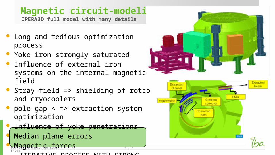
Magnetic circuit-modelingOPERA3D full model with many details
Long and tedious optimization process Yoke iron strongly saturated Influence of external iron systems on the
internal magnetic field Stray-field => shielding of rotco and
cryocoolers pole gap < => extraction system optimization Influence of yoke penetrations Median plane errors Magnetic forces
ITERATIVE PROCESS WITH STRONG INTERACTION TO BEAM SIMULATIONS
Protect, Enhance and Save Lives - 8 -
1. The magnet load line with respect to the superconductor critical surface
Magnetic field distribution on the coil Maximum field on the coil vs main coil current Compare with critical currents at different temperature
2. The static self-inductance of the magnet From stored energy From flux-linking
3. The dynamic self-inductance of the magnet Essential for non-linear systems like S2C2
The static Opera2D modelWhat information can we obtain
Protect, Enhance and Save Lives - 9 -
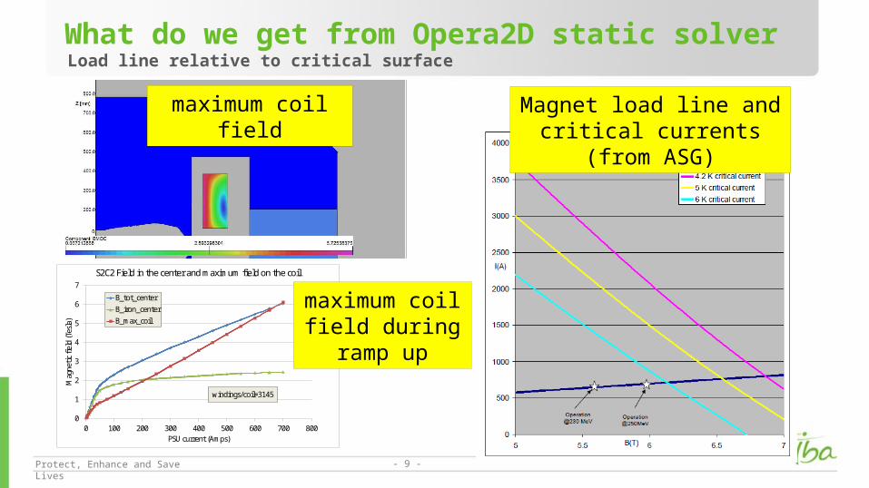
What do we get from Opera2D static solverLoad line relative to critical surface
0
1
2
3
4
5
6
7
0 100 200 300 400 500 600 700 800
Mag
netic
fiel
d (T
esla
)
PSU current (Amps)
S2C2 Field in the center and maximum field on the coil
B_tot_centerB_iron_centerB_max_coil
windings/coil=3145
maximum coil field Magnet load line and critical currents (from ASG)
maximum coil field during
ramp up
Protect, Enhance and Save Lives - 10 -
1. The static self-inductance of the magnet From the stored energy: L From flux-linking:
Flux for a single wire in the coil: Relation with vector potential: Total flux over coil: Self of one coil from flux-linking:
2nd method allows to find difference between upper and lower coil Can be calculated directly in Opera2D
The static self-inductance of the magnet

Protect, Enhance and Save Lives - 11 -
Self-inductance from stored energyCalculated with Opera2D static solver
00
50
100
150
200
250
300
350
400
0
2
4
6
8
10
12
14
16
0 100 200 300 400 500 600 700 800
Self
(Hen
ri)
stor
ed e
nerg
y (M
J)
PSU current (Amps)
S2C2 Stored energy and self-inductance
stored energy
static self
windings/coil=3145

Protect, Enhance and Save Lives - 12 -
Static self from flux-linkingAsymmetry may induce a quench? => probably not; DV=0.3 mV is too small
0
80
160
240
320
400
0
2
4
6
8
10
0 100 200 300 400 500 600 700 800
L tot(H
enri)
L up-L
low
(mH
)PSU current (Amps)
Asymmetry in self-inductance of upper and lower coil
L(upper coil)-L(lower coil)
self
windings/coil=3145
Small vertical symmetry in the model
Introduces a voltage difference between upper and
lower coil during ramp
0.3 mV

Protect, Enhance and Save Lives - 13 -
What do we get from the 2D transient solver?Eddy currents and related losses
0.0
0.2
0.4
0.6
0.8
1.0
1.2
1.4
1.6
1.8
0 50 100 150 200
Loss
es (W
att)
Magnet current (Amps)
Losses in former, cryostat walls and yoke iron during a ramp
former
iron yoke
cryo-walls
ramp-rate=2.7 Amps/min
Current density profiles Losses
Apply a constant ramp rate of 2.7 Amps/min to the coils
Protect, Enhance and Save Lives - 14 -
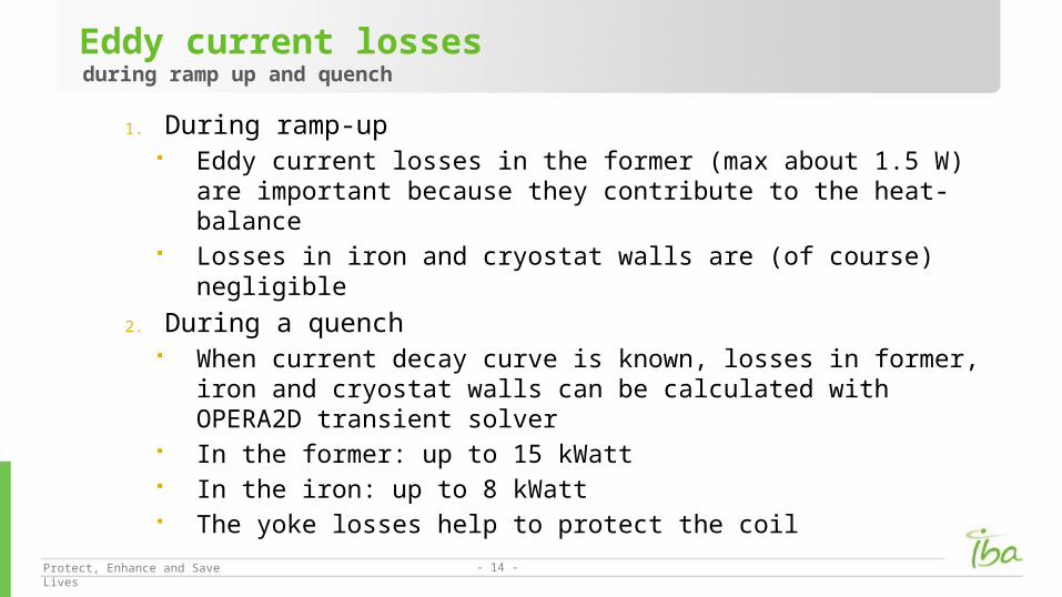
1. During ramp-up Eddy current losses in the former (max about 1.5 W) are important
because they contribute to the heat-balance Losses in iron and cryostat walls are (of course) negligible
2. During a quench When current decay curve is known, losses in former, iron and cryostat
walls can be calculated with OPERA2D transient solver In the former: up to 15 kWatt In the iron: up to 8 kWatt The yoke losses help to protect the coil
Eddy current lossesduring ramp up and quench
Protect, Enhance and Save Lives - 15 -
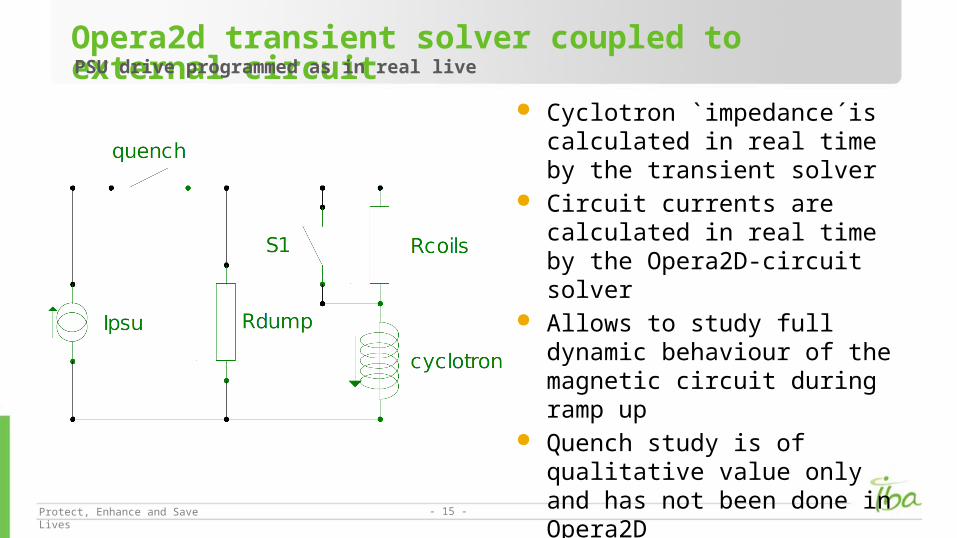
Opera2d transient solver coupled to external circuit PSU drive programmed as in real live
Cyclotron `impedance´is calculated in real time by the transient solver
Circuit currents are calculated in real time by the Opera2D-circuit solver
Allows to study full dynamic behaviour of the magnetic circuit during ramp up
Quench study is of qualitative value only and has not been done in Opera2D
Protect, Enhance and Save Lives - 16 -
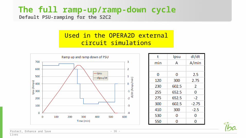
The full ramp-up/ramp-down cycleDefault PSU-ramping for the S2C2
Used in the OPERA2D external circuit simulations

Protect, Enhance and Save Lives - 17 -
A full ramp-up and ramp-down cycleCoil current compared to dump current
It is seen that for a given PSU current the magnetic field in the cyclotron is different for ramp-up as compared to ramp-down
This is due to the fact the dump-current changes sign when ramping down
Higher coil currents in down ramp
up
downcoil
Dump (x10)

Protect, Enhance and Save Lives - 18 -
Tierod-forces during ramp-up and ramp-downSeems to be in agreement with previous slide
Larger forces during down ramp However:
Current split between dump and coil can not explain completely the difference in forces
iron hysteresis also seems to play an important role
0
10
20
30
40
50
60
-60
-50
-40
-30
-20
-10
0
200 300 400 500 600 700
tota
l (kN
)
Fx,F
y (k
N)
PSU-current (Amps)
Horizontal forces on cold mass (040613)
Fx
Fy
total

Protect, Enhance and Save Lives - 19 -
Hysteresis losses (W/m3)
Coupling losses (W/m3)
Tool developed in Opera2D-Transient solver that integrates above expressions in coil area
AC losses during ramp-upFrom Martin Wilson course on superconducting magnets
𝑃 𝑓=𝜆𝑠𝑢𝑝23𝜋
𝐽 𝑐(𝐵)𝑑𝑓𝑑𝐵𝑑𝑡
𝑃𝑒=𝜆𝑤𝑖𝑟𝑒
( 𝑑𝐵𝑑𝑡
)2
𝜌𝑡( 𝑝2𝜋
)2
Jc(B) => critical current densitydf => filament diameterlsup => fraction of NbTi materiallwire => fraction of wire in channelrt => resitivity across wirep => pitch of the wiredB/dt => B-time derivative in coil

Protect, Enhance and Save Lives - 20 -
Critical surface => Bottura formulaNeeded for AC losses calculation
Bottura formula
(reduced temperature)
(reduced field)
critical field at zero current
, ,a b g,C0 => fitting coefficients

Protect, Enhance and Save Lives - 21 -
Critical surface => Bottura formula (2)
0
1
2
3
4
5
6
7
0 2 4 6 8 10 12
Criti
cal c
urre
nt (n
orm
alize
d)
Magnetic field (Tesla)
Critical surface at T=4 K (Bottura-formula)
SpencerSomerkoskiGreenMorganHudson
Normalized to unity at 5 Tesla/4.2 K
0
2
4
6
8
10
12
14
16
0 1 2 3 4 5 6 7 8 9 10
criti
cal fi
eld
(Tes
la)
Temperature (K)
Critical field as function of temperatue at zero current (Bottura)
SpencerSomerkoskiGreenMorganHudson
Protect, Enhance and Save Lives - 22 -
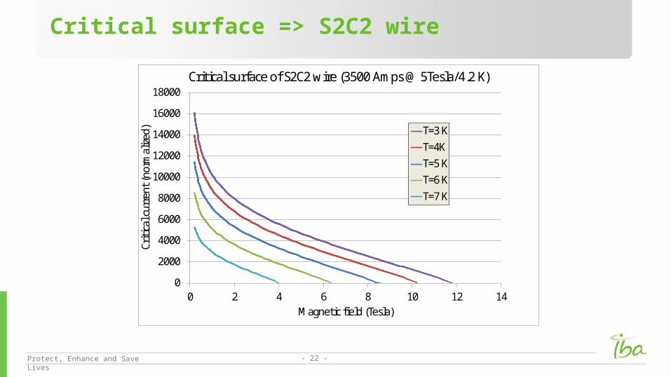
Critical surface => S2C2 wire
0
2000
4000
6000
8000
10000
12000
14000
16000
18000
0 2 4 6 8 10 12 14
Criti
cal c
urre
nt (n
orm
alize
d)
Magnetic field (Tesla)
Critical surface of S2C2 wire (3500 Amps @ 5Tesla/4.2 K)
T=3 KT=4KT=5 KT=6 KT=7 K

Protect, Enhance and Save Lives - 23 -
AC losses obtained with OPER2D transient solverInitial results => maybe can be improved
Hysteresis losses somewhat larger than eddy current losses
Coupling losses very small
Protect, Enhance and Save Lives - 24 -
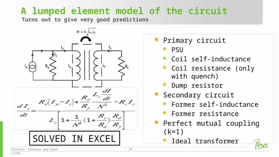
A lumped element model of the circuitTurns out to give very good predictions
Primary circuit PSU Coil self-inductance Coil resistance (only with quench) Dump resistor
Secondary circuit Former self-inductance Former resistance
Perfect mutual coupling (k=1) Ideal transformer
𝑑 𝐼 𝑐𝑑𝑡
=𝑅𝑑 ( 𝐼𝑝− 𝐼 𝑐)+
𝑅𝑑
𝑅𝑓
𝐿𝑐𝑑𝐼𝑑𝑡
𝑁 2 −𝑅𝑐 𝐼𝑐
𝐿𝑐 [1+ 1
𝑁 2 (1+𝑅𝑐
𝑅𝑑
)𝑅𝑑
𝑅 𝑓 ]SOLVED IN EXCEL
Protect, Enhance and Save Lives - 25 -
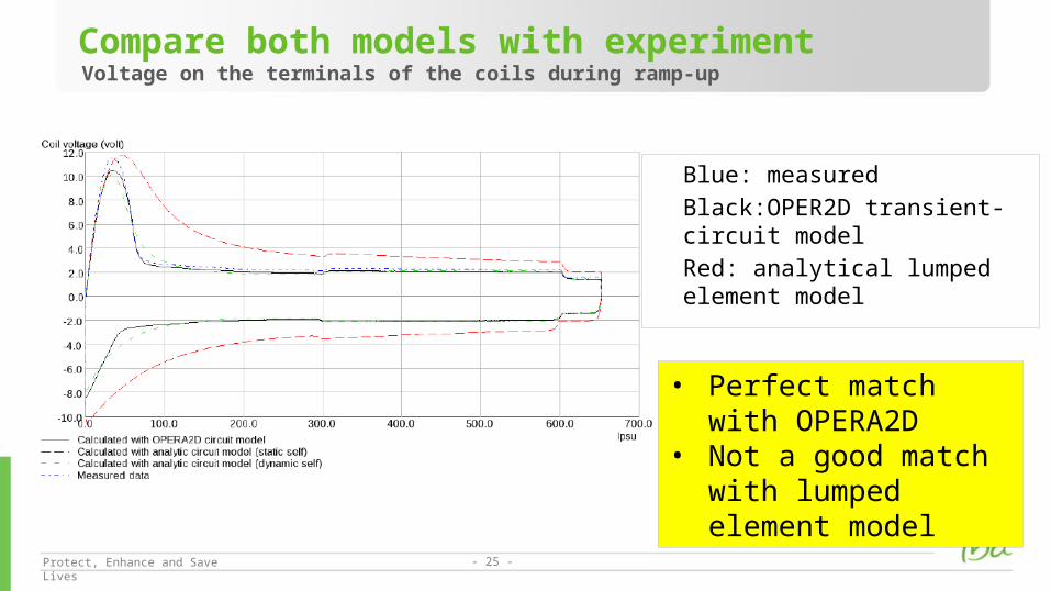
Compare both models with experimentVoltage on the terminals of the coils during ramp-up
Blue: measured
Black:OPER2D transient-circuit model
Red: analytical lumped element model
• Perfect match with OPERA2D
• Not a good match with lumped element model

Protect, Enhance and Save Lives - 26 -
Definition of self-inductance: Faraday’s law: Combine:
For a non-linear system the dynamic self must be used in lumped element circuit simulations
The concept of dynamic self-inductanceImportant for non-linear magnets
Protect, Enhance and Save Lives - 27 -
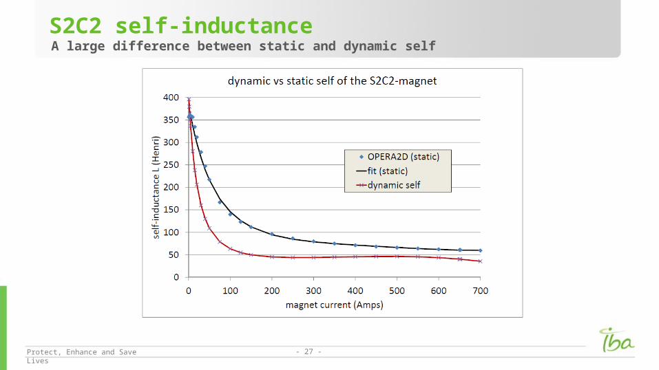
S2C2 self-inductanceA large difference between static and dynamic self

Protect, Enhance and Save Lives - 28 -
Compare both models with experimentVoltage on the terminals of the coils during ramp-up
Blue: measured
Black:OPER2D transient-circuit model
Red: analytical lumped element model with static self
Green: analytical lumped element with dynamic self
An almost perfect match is obtained

Protect, Enhance and Save Lives - 29 -
Compare both circuit-modelsResistive losses in the former during ramp-up
Blue:OPER2D transient-circuit model
Red: analytical lumped element model
Very good agreement
between both models
Protect, Enhance and Save Lives - 30 -
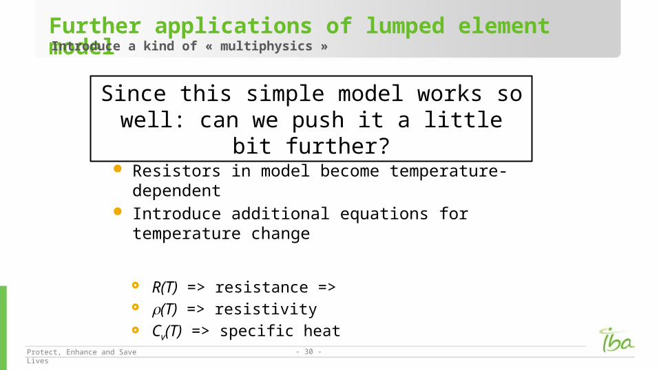
Resistors in model become temperature-dependent Introduce additional equations for temperature change
R(T) => resistance => r(T) => resistivity Cv(T) => specific heat
Further applications of lumped element modelIntroduce a kind of « multiphysics »
Since this simple model works so well: can we push it a little bit further?

Protect, Enhance and Save Lives - 31 -
Specific heat of copper and aluminiumVery accurate fitting is possible

Protect, Enhance and Save Lives - 32 -
Electrical resistivity of copper and aluminiumSame kind of fitting is possible

Protect, Enhance and Save Lives - 33 -
Five different zones with four different temperatures in the cold mass1. Upper coil superconducting zone (T0)
2. Upper coil resistive zone heated by resistive loss (T1) expanding due to longitudinal and transverse quench propagation
3. Resistive former heated by eddy current losses (T2)
4. Lower coil superconducting zone (T0)
5. Lower coil resistive zone heated by resistive loss (T3) expanding due to longitudinal and transverse quench propagation
Start quench in upper coil Lower coil will quench when former temperature above critical
temperature ADIABATIC APPROXIMATION => no heat exchange between zones
A qualitative model for quench behaviorBased on (« multi-physics ») lumped element model

Protect, Enhance and Save Lives - 34 -
Introduce the fraction f=fl*ft of the coil that has become resistive
1. fl => Longitudinal propagation (fast 10 m/sec):
2. ft =>Transverse propagation (slow 20 cm/sec):
Model for quench propagationFrom Wilson course
𝑑𝑙𝑑𝑡
=𝑣 𝑙𝑜𝑛𝑔⇒𝑣 𝑙𝑜𝑛𝑔=𝐽
𝛾 𝐶𝑣 √ 𝐿0 𝜃0𝜃𝑡−𝜃0
𝑑𝑟𝑑𝑡
=𝑣𝑡𝑟𝑎𝑛𝑠⇒𝑣𝑡𝑟𝑎𝑛𝑠=𝛼𝑣 𝑙𝑜𝑛𝑔
J => current densityG => mass densityCv => specific heatq0 => base temperatureqt => contact temperatureL0 => Lorentz number

Protect, Enhance and Save Lives - 35 -
Resistive loss per m3 equals increase of enthalpy per m3
Where J is current density and g is mass density
Allows to calculate Tmax also from a measured decay curve
Maximum temperature in the coilOccurs at position where the quench started
𝐽 2 (𝑡 )𝜌 (𝑇 )𝑑𝑡=𝛾𝐶𝑣 (𝑇 )𝑑𝑇
𝑑𝑇𝑚𝑎𝑥
𝑑𝑡= 𝐽 2𝜌𝛾 𝐶𝑣
Protect, Enhance and Save Lives - 36 -
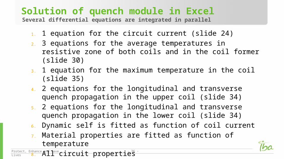
1. 1 equation for the circuit current (slide 24)
2. 3 equations for the average temperatures in resistive zone of both coils and in the coil former (slide 30)
3. 1 equation for the maximum temperature in the coil (slide 35)
4. 2 equations for the longitudinal and transverse quench propagation in the upper coil (slide 34)
5. 2 equations for the longitudinal and transverse quench propagation in the lower coil (slide 34)
6. Dynamic self is fitted as function of coil current
7. Material properties are fitted as function of temperature
8. All circuit properties (currents,voltages,resistances,losses) are obtained
Solution of quench module in ExcelSeveral differential equations are integrated in parallel
Protect, Enhance and Save Lives - 37 -
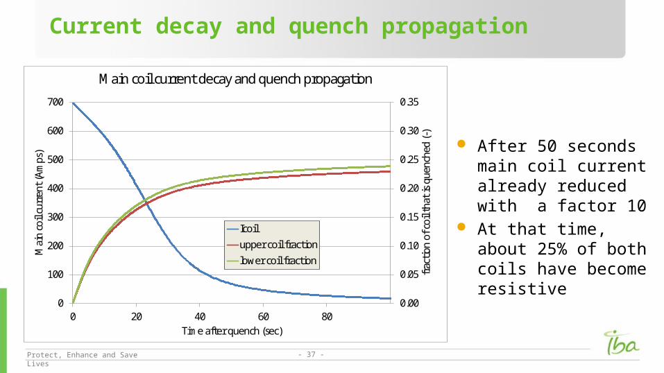
Current decay and quench propagation
After 50 seconds main coil current already reduced with a factor 10
At that time, about 25% of both coils have become resistive
0.00
0.05
0.10
0.15
0.20
0.25
0.30
0.35
0
100
200
300
400
500
600
700
0 20 40 60 80
frac
tion
of c
oil t
hat i
s qu
ench
ed (-
)
Mai
n co
il cu
rren
t (Am
ps)
Time after quench (sec)
Main coil current decay and quench propagation
Icoil
upper coil fraction
lower coil fraction
Protect, Enhance and Save Lives - 38 -
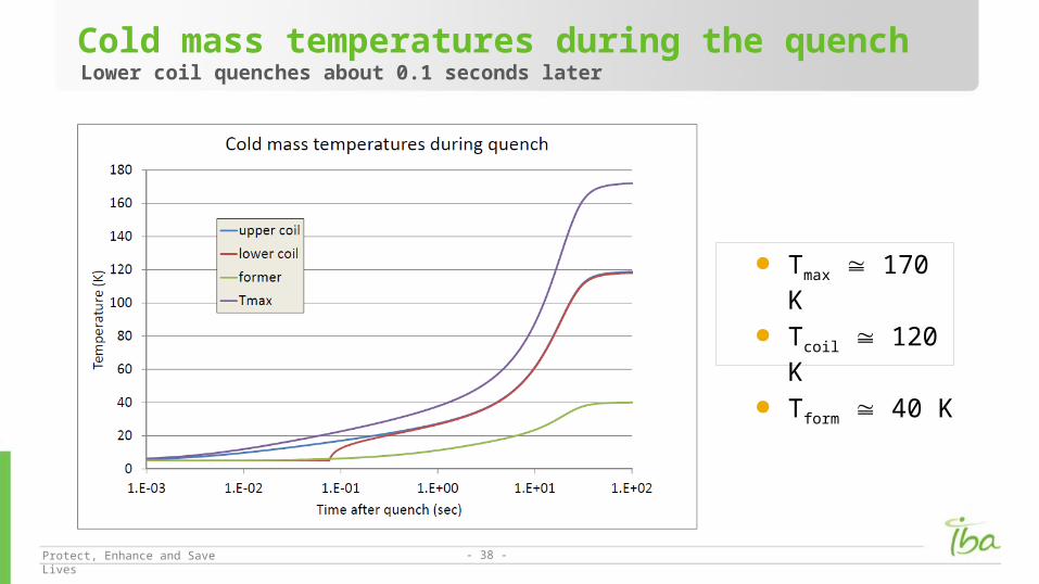
Cold mass temperatures during the quenchLower coil quenches about 0.1 seconds later
Tmax 170 K Tcoil 120 K Tform 40 K

Protect, Enhance and Save Lives - 39 -
Ohmic losses during the quenchIron losses may be obtained from Opera2D transient solver
Protect, Enhance and Save Lives - 40 -
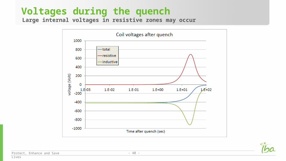
Voltages during the quenchLarge internal voltages in resistive zones may occur
Protect, Enhance and Save Lives - 41 -
Many things have to be learned; this is only a start on one aspect For learning we have to start doing For example study of the quench problem will force us to learn:
1. More about material properties
2. More about heat transport in the cold mass
3. More about mechanical/thermal stress in the coldmass
4. Multi-physics approach
5. …. A precise quench study needs to be done with 3D finite element codes
Quench model in Opera3D? Comsol ?
Conclusions