dynamic binary translation for embedded systems...
TRANSCRIPT
DYNAMIC BINARY TRANSLATION FOR EMBEDDED
SYSTEMS WITH SCRATCHPAD MEMORY
by
Jose Americo Baiocchi Paredes
B.S., Pontificia Universidad Catolica del Peru, 2002
M.S., University of Pittsburgh, 2009
Submitted to the Graduate Faculty of
the Department of Computer Science in partial fulfillment
of the requirements for the degree of
Doctor of Philosophy
University of Pittsburgh
2011

UNIVERSITY OF PITTSBURGH
DEPARTMENT OF COMPUTER SCIENCE
This dissertation was presented
by
Jose Americo Baiocchi Paredes
It was defended on
November 11th 2011
and approved by
Bruce R. Childers, Associate Professor, Department of Computer Science
Sangyeun Cho, Associate Professor, Department of Computer Science
Youtao Zhang, Associate Professor, Department of Computer Science
Jack W. Davidson, Professor, University of Virginia
Dissertation Director: Bruce R. Childers, Associate Professor, Department of Computer Science
ii
Copyright c© by Jose Americo Baiocchi Paredes
2011
iii

DYNAMIC BINARY TRANSLATION FOR EMBEDDED SYSTEMS WITH SCRATCHPAD
MEMORY
Jose Americo Baiocchi Paredes, PhD
University of Pittsburgh, 2011
Embedded software development has recently changed with advances in computing. Rather than
fully co-designing software and hardware to perform a relatively simple task, nowadays embed-
ded and mobile devices are designed as a platform where multiple applications can be run, new
applications can be added, and existing applications can be updated. In this scenario, traditional
constraints in embedded systems design (i.e., performance, memory and energy consumption and
real-time guarantees) are more difficult to address. New concerns (e.g., security) have become im-
portant and increase software complexity as well.
In general-purpose systems, Dynamic Binary Translation (DBT) has been used to address these
issues with services such as Just-In-Time (JIT) compilation, dynamic optimization, virtualization,
power management and code security. In embedded systems, however, DBT is not usually em-
ployed due to performance, memory and power overhead.
This dissertation presents StrataX, a low-overhead DBT framework for embedded systems.
StrataX addresses the challenges faced by DBT in embedded systems using novel techniques.
To reduce DBT overhead, StrataX loads code from NAND-Flash storage and translates it into a
Scratchpad Memory (SPM), a software-managed on-chip SRAM with limited capacity. SPM has
similar access latency as a hardware cache, but consumes less power and area.
StrataX manages SPM as a software instruction cache, and employs victim compression and
pinning to reduce retranslation cost and capture frequently executed code in the SPM. To prevent
performance loss due to excessive code expansion, StrataX minimizes the amount of code inserted
by DBT to maintain control of program execution. When a hardware instruction cache is avail-
able, StrataX dynamically partitions translated code among the SPM and main memory. With
these techniques, StrataX has low performance overhead relative to native execution for MiBench
iv

programs. Further, it simplifies embedded software and hardware design by operating trans-
parently to applications without any special hardware support. StrataX achieves sufficiently low
overhead to make it feasible to use DBT in embedded systems to address important design goals
and requirements.
v

TABLE OF CONTENTS
PREFACE . . . . . . . . . . . . . . . . . . . . . . . . . . . . . . . . . . . . . . . . . . . . . . . . xiv
1.0 INTRODUCTION . . . . . . . . . . . . . . . . . . . . . . . . . . . . . . . . . . . . . . . . 1
1.1 CHALLENGES . . . . . . . . . . . . . . . . . . . . . . . . . . . . . . . . . . . . . . . . 3
1.1.1 Memory constraints . . . . . . . . . . . . . . . . . . . . . . . . . . . . . . . . . . 3
1.1.2 Performance constraints . . . . . . . . . . . . . . . . . . . . . . . . . . . . . . . 3
1.1.3 Heterogeneous memory resources . . . . . . . . . . . . . . . . . . . . . . . . . 4
1.2 RESEARCH OVERVIEW . . . . . . . . . . . . . . . . . . . . . . . . . . . . . . . . . . 5
1.3 RESEARCH SCOPE . . . . . . . . . . . . . . . . . . . . . . . . . . . . . . . . . . . . . 6
1.4 DOCUMENT ORGANIZATION . . . . . . . . . . . . . . . . . . . . . . . . . . . . . . 7
2.0 BACKGROUND AND RELATED WORK . . . . . . . . . . . . . . . . . . . . . . . . . . 8
2.1 BASIC CONCEPTS . . . . . . . . . . . . . . . . . . . . . . . . . . . . . . . . . . . . . . 8
2.2 DYNAMIC BINARY TRANSLATION . . . . . . . . . . . . . . . . . . . . . . . . . . . 12
2.2.1 Types of DBT systems . . . . . . . . . . . . . . . . . . . . . . . . . . . . . . . . 12
2.2.2 DBT services . . . . . . . . . . . . . . . . . . . . . . . . . . . . . . . . . . . . . . 13
2.2.3 DBT implementation . . . . . . . . . . . . . . . . . . . . . . . . . . . . . . . . . 17
2.2.3.1 Fragment Formation . . . . . . . . . . . . . . . . . . . . . . . . . . . . . 17
2.2.3.2 Overhead Reduction Techniques . . . . . . . . . . . . . . . . . . . . . . 19
2.2.3.3 Trace Formation . . . . . . . . . . . . . . . . . . . . . . . . . . . . . . . 20
2.2.3.4 Fragment Cache Management . . . . . . . . . . . . . . . . . . . . . . . 20
2.2.4 DBT in Embedded Systems . . . . . . . . . . . . . . . . . . . . . . . . . . . . . 23
2.3 SCRATCHPAD MEMORY . . . . . . . . . . . . . . . . . . . . . . . . . . . . . . . . . 24
2.3.1 Scratchpad memory allocation . . . . . . . . . . . . . . . . . . . . . . . . . . . 25
2.3.1.1 Static allocation . . . . . . . . . . . . . . . . . . . . . . . . . . . . . . . 25
2.3.1.2 Dynamic allocation . . . . . . . . . . . . . . . . . . . . . . . . . . . . . 28
vi

2.3.2 SPM address translation . . . . . . . . . . . . . . . . . . . . . . . . . . . . . . . 29
2.3.2.1 Software caching . . . . . . . . . . . . . . . . . . . . . . . . . . . . . . . 29
2.3.2.2 Hardware-assisted address translation . . . . . . . . . . . . . . . . . . 30
2.3.3 SPM sharing . . . . . . . . . . . . . . . . . . . . . . . . . . . . . . . . . . . . . . 31
2.4 FLASH MEMORY . . . . . . . . . . . . . . . . . . . . . . . . . . . . . . . . . . . . . . 32
2.4.1 Code Execution from NAND Flash . . . . . . . . . . . . . . . . . . . . . . . . . 32
3.0 STRATAX FRAMEWORK FOR MEMORY-CONSTRAINED EMBEDDED SYSTEMS 34
3.1 TARGET SYSTEM . . . . . . . . . . . . . . . . . . . . . . . . . . . . . . . . . . . . . . 34
3.2 SYSTEM-ON-CHIP SIMULATOR . . . . . . . . . . . . . . . . . . . . . . . . . . . . . 36
3.2.1 Dynamic code generation . . . . . . . . . . . . . . . . . . . . . . . . . . . . . . 36
3.2.2 Dynamic memory allocation . . . . . . . . . . . . . . . . . . . . . . . . . . . . . 37
3.2.2.1 SPM simulation . . . . . . . . . . . . . . . . . . . . . . . . . . . . . . . 38
3.2.3 NAND Flash simulation . . . . . . . . . . . . . . . . . . . . . . . . . . . . . . . 38
3.3 STRATAX OVERVIEW . . . . . . . . . . . . . . . . . . . . . . . . . . . . . . . . . . . 40
3.3.1 Operation . . . . . . . . . . . . . . . . . . . . . . . . . . . . . . . . . . . . . . . 40
3.3.2 Architecture . . . . . . . . . . . . . . . . . . . . . . . . . . . . . . . . . . . . . . 42
3.3.3 Approaches . . . . . . . . . . . . . . . . . . . . . . . . . . . . . . . . . . . . . . 43
3.3.3.1 Bounded fragment cache . . . . . . . . . . . . . . . . . . . . . . . . . . 43
3.3.3.2 Translated code footprint reduction . . . . . . . . . . . . . . . . . . . . 44
3.3.3.3 Fragment cache management . . . . . . . . . . . . . . . . . . . . . . . 45
3.3.4 Implementation . . . . . . . . . . . . . . . . . . . . . . . . . . . . . . . . . . . . 45
3.3.4.1 Translation . . . . . . . . . . . . . . . . . . . . . . . . . . . . . . . . . . 46
3.3.4.2 Fragment formation . . . . . . . . . . . . . . . . . . . . . . . . . . . . . 46
3.3.4.3 Trampolines . . . . . . . . . . . . . . . . . . . . . . . . . . . . . . . . . 48
3.3.4.4 Fragment cache management . . . . . . . . . . . . . . . . . . . . . . . 49
3.3.4.5 Fragment linking and unlinking . . . . . . . . . . . . . . . . . . . . . . 49
3.3.4.6 System call handling . . . . . . . . . . . . . . . . . . . . . . . . . . . . 50
3.4 EXPERIMENTAL METHODOLOGY . . . . . . . . . . . . . . . . . . . . . . . . . . . 51
4.0 CODE GENERATION . . . . . . . . . . . . . . . . . . . . . . . . . . . . . . . . . . . . . . 54
4.1 PERFORMANCE OF SMALL FRAGMENT CACHES . . . . . . . . . . . . . . . . . . 54
4.2 FRAGMENT FORMATION STRATEGY . . . . . . . . . . . . . . . . . . . . . . . . . 59
4.3 CONTROL CODE FOOTPRINT REDUCTION . . . . . . . . . . . . . . . . . . . . . . 64
vii
4.3.1 Translated Code Composition Without Footprint Reduction . . . . . . . . . . 64
4.3.2 Performance Without Footprint Reduction . . . . . . . . . . . . . . . . . . . . 67
4.3.3 Reducing Trampoline Size . . . . . . . . . . . . . . . . . . . . . . . . . . . . . . 70
4.3.3.1 Alternative Trampoline Designs . . . . . . . . . . . . . . . . . . . . . . 71
4.3.3.2 Evaluation . . . . . . . . . . . . . . . . . . . . . . . . . . . . . . . . . . 73
4.3.4 Reducing Indirect CTI Handling Code Size . . . . . . . . . . . . . . . . . . . . 74
4.3.4.1 Alternative IBTC Lookup Designs . . . . . . . . . . . . . . . . . . . . . 75
4.3.4.2 Evaluation . . . . . . . . . . . . . . . . . . . . . . . . . . . . . . . . . . 77
4.3.5 Eliminating the Fragment Prologue . . . . . . . . . . . . . . . . . . . . . . . . . 78
4.3.5.1 Self-Modifying Control Transfer . . . . . . . . . . . . . . . . . . . . . . 79
4.3.5.2 Bottom Jump Eliding . . . . . . . . . . . . . . . . . . . . . . . . . . . . 80
4.3.5.3 Evaluation . . . . . . . . . . . . . . . . . . . . . . . . . . . . . . . . . . 81
4.3.6 Translated Code Composition with Footprint Reduction . . . . . . . . . . . . 84
4.3.7 Performance With Footprint Reduction . . . . . . . . . . . . . . . . . . . . . . 84
5.0 FRAGMENT CACHE MANAGEMENT . . . . . . . . . . . . . . . . . . . . . . . . . . . 88
5.1 FRAGMENT CACHE LAYOUT . . . . . . . . . . . . . . . . . . . . . . . . . . . . . . 88
5.1.1 Fragment Cache Layout Alternatives . . . . . . . . . . . . . . . . . . . . . . . . 89
5.1.2 Trampoline Pool Management . . . . . . . . . . . . . . . . . . . . . . . . . . . 90
5.1.3 Evaluation . . . . . . . . . . . . . . . . . . . . . . . . . . . . . . . . . . . . . . . 91
5.2 HETEROGENEOUS FRAGMENT CACHE MANAGEMENT . . . . . . . . . . . . . 94
5.2.1 Heterogeneous Fragment Cache Allocation . . . . . . . . . . . . . . . . . . . . 94
5.2.2 Basic Heterogeneous Fragment Cache Management . . . . . . . . . . . . . . . 95
5.2.2.1 Eviction Policies . . . . . . . . . . . . . . . . . . . . . . . . . . . . . . . 95
5.2.2.2 Resizing Heuristic . . . . . . . . . . . . . . . . . . . . . . . . . . . . . . 96
5.2.2.3 Evaluation . . . . . . . . . . . . . . . . . . . . . . . . . . . . . . . . . . 96
5.2.3 SPM-Aware Translation . . . . . . . . . . . . . . . . . . . . . . . . . . . . . . . 98
5.2.3.1 Evaluation . . . . . . . . . . . . . . . . . . . . . . . . . . . . . . . . . . 99
5.2.4 Comparison to Homogeneous Fragment Cache . . . . . . . . . . . . . . . . . . 100
5.3 SCRATCHPAD FRAGMENT CACHE MANAGEMENT . . . . . . . . . . . . . . . . 103
5.3.1 Victim Compression . . . . . . . . . . . . . . . . . . . . . . . . . . . . . . . . . 103
5.3.1.1 Dynamic SPM Partitioning . . . . . . . . . . . . . . . . . . . . . . . . . 104
5.3.1.2 Compression and Decompression . . . . . . . . . . . . . . . . . . . . . 105
viii

5.3.1.3 Evaluation . . . . . . . . . . . . . . . . . . . . . . . . . . . . . . . . . . 106
5.3.2 Fragment Pinning . . . . . . . . . . . . . . . . . . . . . . . . . . . . . . . . . . . 107
5.3.2.1 Pinning and Release Strategies . . . . . . . . . . . . . . . . . . . . . . . 108
5.3.2.2 Evaluation . . . . . . . . . . . . . . . . . . . . . . . . . . . . . . . . . . 109
5.3.3 Overall Improvement . . . . . . . . . . . . . . . . . . . . . . . . . . . . . . . . . 110
5.4 DEMAND PAGING FOR NAND FLASH . . . . . . . . . . . . . . . . . . . . . . . . . 113
5.4.1 Scattered Page Buffer . . . . . . . . . . . . . . . . . . . . . . . . . . . . . . . . . 113
5.4.1.1 Evaluation . . . . . . . . . . . . . . . . . . . . . . . . . . . . . . . . . . 115
5.4.2 Unified Code Buffer . . . . . . . . . . . . . . . . . . . . . . . . . . . . . . . . . 119
5.4.2.1 Evaluation . . . . . . . . . . . . . . . . . . . . . . . . . . . . . . . . . . 121
5.4.3 Asynchronous Loading . . . . . . . . . . . . . . . . . . . . . . . . . . . . . . . . 122
5.4.3.1 Evaluation . . . . . . . . . . . . . . . . . . . . . . . . . . . . . . . . . . 123
6.0 CONCLUSIONS AND FUTURE WORK . . . . . . . . . . . . . . . . . . . . . . . . . . . 126
6.1 SUMMARY OF CONTRIBUTIONS . . . . . . . . . . . . . . . . . . . . . . . . . . . . 126
6.2 FUTURE WORK . . . . . . . . . . . . . . . . . . . . . . . . . . . . . . . . . . . . . . . 128
BIBLIOGRAPHY . . . . . . . . . . . . . . . . . . . . . . . . . . . . . . . . . . . . . . . . . . . . 130
ix
LIST OF TABLES
2.1 SPM allocation approaches . . . . . . . . . . . . . . . . . . . . . . . . . . . . . . . . . . 26
3.1 PISA instruction handling examples . . . . . . . . . . . . . . . . . . . . . . . . . . . . 47
3.2 StrataX fragment formation options . . . . . . . . . . . . . . . . . . . . . . . . . . . . . 48
3.3 PXA270 SimpleScalar Configuration . . . . . . . . . . . . . . . . . . . . . . . . . . . . 51
3.4 ARM926 SimpleScalar Configuration . . . . . . . . . . . . . . . . . . . . . . . . . . . . 52
3.5 ARM1176 SimpleScalar Configuration . . . . . . . . . . . . . . . . . . . . . . . . . . . 53
4.1 Number of flushes for 64KB, 32KB, and 16KB fragment caches . . . . . . . . . . . . . 58
4.2 Evaluated fragment formation strategies . . . . . . . . . . . . . . . . . . . . . . . . . . 60
5.1 Final fragment cache size . . . . . . . . . . . . . . . . . . . . . . . . . . . . . . . . . . . 102
5.2 Speedup (slowdown) with victim compression . . . . . . . . . . . . . . . . . . . . . . 107
5.3 Number of flushes without and with fragment pinning . . . . . . . . . . . . . . . . . 110
5.4 Speedup (slowdown) with fragment pinning . . . . . . . . . . . . . . . . . . . . . . . 111
5.5 NAND Flash pages read (512 bytes/page) . . . . . . . . . . . . . . . . . . . . . . . . . 116
5.6 NAND Flash pages read with UCB-75% . . . . . . . . . . . . . . . . . . . . . . . . . . 122
x

LIST OF FIGURES
2.1 Program Representation and Execution . . . . . . . . . . . . . . . . . . . . . . . . . . . 9
2.2 Abstraction Layers . . . . . . . . . . . . . . . . . . . . . . . . . . . . . . . . . . . . . . . 11
2.3 A DBT system . . . . . . . . . . . . . . . . . . . . . . . . . . . . . . . . . . . . . . . . . 12
2.4 Types of DBT systems . . . . . . . . . . . . . . . . . . . . . . . . . . . . . . . . . . . . . 14
2.5 DBT Overview . . . . . . . . . . . . . . . . . . . . . . . . . . . . . . . . . . . . . . . . . 18
2.6 Processor address space with scratchpad memory . . . . . . . . . . . . . . . . . . . . 25
3.1 Example target SoC . . . . . . . . . . . . . . . . . . . . . . . . . . . . . . . . . . . . . . 35
3.2 SimpleScalar address space use . . . . . . . . . . . . . . . . . . . . . . . . . . . . . . . 37
3.3 StrataX Virtual Machine . . . . . . . . . . . . . . . . . . . . . . . . . . . . . . . . . . . . 41
3.4 StrataX Architecture . . . . . . . . . . . . . . . . . . . . . . . . . . . . . . . . . . . . . . 42
3.5 Fragment unlinking . . . . . . . . . . . . . . . . . . . . . . . . . . . . . . . . . . . . . . 50
4.1 Speedup relative to native execution for a 2MB fragment cache in SDRAM; and frag-
ment caches in 64KB, 32KB and 16KB SPM with FLUSH . . . . . . . . . . . . . . . . . 55
4.2 Slowdown relative to DBB for evaluated fragment formation strategies . . . . . . . . 61
4.3 Percentage of duplicated instruction fetches for different fragment formation strate-
gies . . . . . . . . . . . . . . . . . . . . . . . . . . . . . . . . . . . . . . . . . . . . . . . 62
4.4 Percentage of dead translated code for different fragment formation strategies . . . . 63
4.5 Example fragments with instruction categories . . . . . . . . . . . . . . . . . . . . . . 65
4.6 Initial translated code size for an unbounded fragment cache . . . . . . . . . . . . . . 66
4.7 Slowdown relative to unbounded fragment cache for 64KB, 32KB and 16KB frag-
ment caches in SPM with FLUSH and FIFO . . . . . . . . . . . . . . . . . . . . . . . . 68
4.8 Initial relative 32KB fragment cache usage . . . . . . . . . . . . . . . . . . . . . . . . . 70
4.9 Trampoline design choices . . . . . . . . . . . . . . . . . . . . . . . . . . . . . . . . . . 71
4.10 Performance of trampoline designs for a 32KB fragment cache . . . . . . . . . . . . . 73
xi

4.11 Relative 32KB fragment cache usage after Shadow LR . . . . . . . . . . . . . . . . . . 74
4.12 Indirect CTI handling with an IBTC . . . . . . . . . . . . . . . . . . . . . . . . . . . . . 76
4.13 Performance of IBTC lookup placements for 32KB fragment cache . . . . . . . . . . . 78
4.14 Relative 32KB F$ usage after STRC IBTC lookup . . . . . . . . . . . . . . . . . . . . . 79
4.15 Control transfer to fragment . . . . . . . . . . . . . . . . . . . . . . . . . . . . . . . . . 80
4.16 Bottom Jump Eliding (BJE) . . . . . . . . . . . . . . . . . . . . . . . . . . . . . . . . . . 81
4.17 Performance with SMCS, SMCS-ROM and BJE for 32KB fragment cache . . . . . . . 82
4.18 Relative 32KB F$ usage after BJE . . . . . . . . . . . . . . . . . . . . . . . . . . . . . . . 83
4.19 Final translated code size with footprint reduction for an unbounded fragment cache 85
4.20 Final slowdown with control code footprint reduction relative to initial unbounded
fragment cache . . . . . . . . . . . . . . . . . . . . . . . . . . . . . . . . . . . . . . . . . 86
4.21 Speedup with control code footprint reduction . . . . . . . . . . . . . . . . . . . . . . 87
5.1 Trampoline placement alternatives . . . . . . . . . . . . . . . . . . . . . . . . . . . . . 89
5.2 Slowdown for 32K fragment cache with trampoline pool . . . . . . . . . . . . . . . . 92
5.3 Fragment Cache Allocation Alternatives . . . . . . . . . . . . . . . . . . . . . . . . . . 94
5.4 Slowdown relative to native execution for HFC with FLUSH, Segmented FIFO and
FIFO eviction policies . . . . . . . . . . . . . . . . . . . . . . . . . . . . . . . . . . . . . 97
5.5 Slowdown relative to native execution for HFC with SPM-aware policies . . . . . . . 99
5.6 Slowdown relative to native execution for SFC, HFC and MFC with FLUSH . . . . . 100
5.7 Victim compression and space reclamation . . . . . . . . . . . . . . . . . . . . . . . . . 105
5.8 Incorporating compression and decompression . . . . . . . . . . . . . . . . . . . . . . 106
5.9 Fragment state diagram with pinning . . . . . . . . . . . . . . . . . . . . . . . . . . . . 109
5.10 Final vs. Initial Speedup for 64KB, 32KB and 16KB fragment caches . . . . . . . . . . 112
5.11 Application Binary Loading . . . . . . . . . . . . . . . . . . . . . . . . . . . . . . . . . 114
5.12 Boot time with DBT/SPB relative to DE/FS . . . . . . . . . . . . . . . . . . . . . . . . 117
5.13 Speedup with DBT/SPB relative to DE/FS . . . . . . . . . . . . . . . . . . . . . . . . . 118
5.14 Unified Code Buffer . . . . . . . . . . . . . . . . . . . . . . . . . . . . . . . . . . . . . . 119
5.15 Speedup of DBT/UCB relative to DE/FS . . . . . . . . . . . . . . . . . . . . . . . . . . 123
5.16 Speedup with asynchronous Flash page reads . . . . . . . . . . . . . . . . . . . . . . . 124
xii

LIST OF ALGORITHMS
5.1 Emit New Trampoline in Pool . . . . . . . . . . . . . . . . . . . . . . . . . . . . . . . . 90
5.2 Reclaim Trampoline in Pool . . . . . . . . . . . . . . . . . . . . . . . . . . . . . . . . . 91
5.3 Fetch step with scattered page buffer . . . . . . . . . . . . . . . . . . . . . . . . . . . . 115
5.4 Fetch step with unified code buffer . . . . . . . . . . . . . . . . . . . . . . . . . . . . . 120
xiii
PREFACE
A.M.D.G.
It has been a long journey, with deep downs and high ups; humbling, growthful, life-changing.
And looking back, I can only be thankful for everyone that was there to lend a hand, to give advice,
to listen . . . and to pull me up whenever I needed it.
To the faculty at Pitt CS (in particular, Bruce Childers and Rami Melhem), colleagues, friends,
and family: thank you!
xiv

1.0 INTRODUCTION
Embedded computer systems are continuously increasing in their capabilities. Nowadays, em-
bedded and mobile devices have more computation and communication abilities than general-
purpose computers from just a few years ago. This evolution has made it possible to use these
devices for more demanding applications (e.g., multimedia, image recognition, voice recognition,
advance digital signal processing). It has also led to the convergence of tasks usually handled by
several specialized devices onto a single, more powerful device. For instance, software-defined
radio implements multiple communication standards such as Bluetooth, DECT (cordless phone),
IEEE 802.11a/b/g (wireless LAN), GSM (mobile phone) and TETRA (professional mobile radio)
in a device with a software layer on a single Digital Signal Processor (DSP) [64]. However, tradi-
tional embedded design concerns, i.e., performance, memory capacity, energy consumption and
real-time guarantee, are still important.
New models of software development, such as open source, are now also employed in em-
bedded systems. For instance, Linux-based platforms are used in smart phones (e.g., Android)
and automotive infotainment systems (e.g., MeeGo). In this scenario, the traditional approach of
co-designing all the software that runs in an embedded device along with the device (hardware)
itself can not be easily applied. Instead, a platform is provided that allows third-party developers
to create new applications for embedded and mobile devices, long after the production of the de-
vice hardware. Users often download these applications through the Internet, so many security
concerns arise, such as the protection of user privacy and the Intellectual Property (IP) of device
makers [71]. For instance, a mobile phone maker could provide application developers with a
software library for controlling the communications processor. However, their IP might become
exposed to reverse-engineering by a competitor or a malicious programmer, so some sort of pro-
tection mechanism is needed against these attacks.
These issues can be addressed with the use of Dynamic Binary Translation (DBT). DBT is a
1

powerful technology that provides the ability to modify a program’s binary code as it executes.
With DBT, binary code can be adapted to conditions unforeseen at the time of its original distribu-
tion. In general-purpose systems, DBT has been used to provide many compelling services, such
as processor virtualization [1], platform emulation [11, 31, 32], just-in-time compilation [19, 128],
dynamic optimization [8, 25], dynamic instrumentation [13, 54, 74, 83], power management [127]
and code security [56, 70]. DBT can also be used to provide services specific for embedded sys-
tems, such as on-demand code decompression [30, 106], software caching [79], hardware reconfig-
uration [86] and instruction set extension [73]. Despite these promising uses, the adoption of DBT
in embedded systems has been limited. The reason is the memory and performance overhead that
DBT may impose on systems with tight resource constraints. In particular, DBT techniques often
require more memory resources than typically found in an embedded device. This memory lim-
itation can not be easily overcome by conventional DBT techniques without imposing significant
performance overhead.
Many embedded System-on-Chips (SoCs) incorporate a Scratchpad Memory (SPM) – a fast but
relatively small on-chip SRAM or embedded DRAM – that can replace or complement traditional
hardware caches. A SPM and a hardware cache of the same capacity have similar access latency,
but the former consumes less power and chip area [9]. Unlike a hardware cache, which is trans-
parent to software, the SPM is usually part of the physical address space, so it must be controlled
explicitly by software. Effectively exploiting the fast and low-power SPM can help to alleviate the
performance loss due to DBT.
The overall goal of this thesis is to enable the use of DBT in embedded systems with SPM. For
this purpose, current DBT techniques are studied to identify sources of overhead and other limi-
tations, and novel techniques are proposed to enable the use of DBT in embedded systems. These
novel techniques have been incorporated into a new, extensible DBT framework for embedded
systems, called StrataX. StrataX exploits the fast SPM to mitigate the overhead imposed by DBT.
The hypothesis is that by operating below the application level, and making effective use of
memory resources, StrataX can achieve “good enough” base performance when executing a pro-
gram under DBT. With “good enough” base performance, further DBT-based services can be effi-
ciently provided to the application software executed in embedded devices.
2

1.1 CHALLENGES
Embedded systems present particular challenges to DBT that are addressed in this dissertation.
These challenges arise from memory and performance constraints and the heterogeneity of mem-
ory resources.
1.1.1 Memory constraints
A DBT system for a general-purpose computer often takes control of a program after it has been
loaded into main memory. The DBT system reads the program’s text (code) segment to discover
instructions, and it inspects and possibly modifies those instructions. A group of translated in-
structions is called a fragment. Fragments are stored and executed in a software-managed memory
buffer, called the Fragment Cache (F$). To achieve low runtime overhead, the size of the F$ is of-
ten unbounded to ensure that each fragment in the translated code working set of the program is
generated only once. Past work showed that a general-purpose DBT system with an unbounded
F$ has an average performance overhead of just 2% to 4% over native execution for the SPEC
benchmarks [53].
Embedded devices may lack the memory resources needed to hold a large F$. A study of
desktop applications made a few years ago showed that the F$ size can grow from hundreds of
kilobytes to tens of megabytes [49] for a single application. Memory pressure is further increased
when multiple applications are executed under DBT control, which makes the use of unbounded
F$s impractical even in devices with many megabytes of memory. Thus, to make DBT feasible in
embedded devices, the memory consumption of a DBT system, particularly for translated code,
must be reduced.
1.1.2 Performance constraints
To achieve low runtime overhead, a DBT system must quickly achieve a steady state in which most
of a program’s execution time is spent on already translated code, rather than in translating new
code. With a bounded F$, a F$ overflow will happen if the F$ is smaller than the translated code
working set of the program. To handle a F$ overflow, room must be made in the F$ for storing new
translated code. In general-purpose systems, this is achieved by deleting one or more fragments [8,
48, 49], or by increasing the size of the F$ [12]. When fragments are deleted, a drawback is the
3

possibility of doing it prematurely, i.e., a fragment that was deleted due to a F$ overflow may be
needed again. In that case, the fragment has to be re-translated. Premature fragment deletions
are likely to increase the overhead of DBT because the time spent generating a fragment may not
be amortized by enough executions of that fragment. Furthermore, when untranslated code is
fetched from external (NAND Flash-based) storage, re-translation may have a high cost in both
time and energy.
This problem can be exacerbated by code expansion due to the way DBT systems translate code.
To amortize the overhead of translating a program, translated code tries to take full advantage
of the hardware on which it runs. For instance, generating code with good locality leads to low
hardware cache miss rates [52]. However, good locality is often achieved by eliding jumps and
partially inlining call targets, but these techniques cause instruction sequences to be duplicated.
Furthermore, DBT techniques are often designed without much regard for code expansion [51].
A DBT system usually injects instructions into the translated code for its own purposes. For
instance, typical DBT systems translate instructions on-demand, following the execution path.
Thus, they must insert instructions to regain control when an address that is not yet translated
needs to be executed. After generating the missing fragment, the translator redirects the control
transfer to that fragment to avoid unnecessary context switches, but this may leave a hole in the
translated code [43, 52]. The number of instructions added by a DBT system for its own purposes
may be excessive [43], leading to an increase in the miss rate of the hardware instruction cache [52,
103].
To overcome these problems, DBT techniques are needed to prevent premature code eviction
and to mitigate the high cost of re-translation. Code expansion must also be minimized to reduce
the frequency of F$ overflows and the possibility of premature fragment deletion.
1.1.3 Heterogeneous memory resources
An embedded SoC may have both SPM and hardware instruction cache. Although it might be
possible to fit the translated code working set of a simple application in a small SPM, running
more complex applications will require the use of main memory for executable code. Thus, the
problem of effectively choosing which code to place in SPM and which code in main memory
must be solved.
Many current SPM allocation solutions rely on a compiler [87, 109, 118, 120, 123, 123]. These
4

solutions often produce application binaries for a given SPM size. Such binaries cannot adapt to
a different configuration, i.e., if a bigger SPM is available, part of its capacity will be wasted, and
if the SPM is smaller than expected, it might be impossible to execute the binary. This kind of
approach is inconvenient when applications are distributed through the Internet and expected to
run in a miriad of device configurations. Thus, run-time only approaches are necessary. Recent
work has proposed performing SPM allocation at load time with a custom loader [85] or using a
Memory Management Unit (MMU) to allocate virtual memory pages to the SPM [93]. Other work
has explored the integration of SPM management in the operating system (OS) [94, 96]. However,
these OS solutions for SPM sharing require programmer or compiler intervention to guide the
allocation of code and/or data to the SPM.
In this research, DBT is used to allocate code to the SPM and to manage it at run-time, eliminat-
ing the need for compiler support and custom binaries tied to a particular resource configuration.
For this purpose, novel F$ management strategies are devised to provide use the SPM for trans-
lated code.
1.2 RESEARCH OVERVIEW
The overall goal of this research is to enable the use of DBT in embedded systems with SPM. To
achieve this main goal, four sub-goals must be accomplished, which address the challenges just
described.
The first sub-goal is to reduce the memory requirements of DBT, specifically the amount of
memory used to hold code (due to the relatively small size of the SPM). The size of the F$ is
bounded to prevent out-of-memory exceptions during application execution. Bounding the size
of the F$ allows placing it in fast SPM. Unfortunately, this bounding may lead to an excessive
number of F$ overflows and premature fragment deletions.
The DBT system is also modified to access the original application code directly from a binary
in external (NAND Flash-based) storage, in order to eliminate the need for a resident text (code)
segment. However, accessing the untranslated code from the external binary is expensive (both in
time and energy), so DBT techniques for reducing the re-translation cost of prematurely evicted
code are devised.
The second sub-goal is to reduce the pressure on the bounded F$. To do so, the translation
5

process is tuned and modified (when necessary) to minimize code expansion. Specifically, the de-
sign of the code introduced by a DBT system to remain in control of execution must be modified
to minimize the number of instructions emitted in the F$ for transferring control from the trans-
lated code to the translator and viceversa. Additionally, several fragment formation policies are
evaluated to choose one that produces the smallest amount of duplicated and dead code.
The third sub-goal is to efficiently exploit the different types of memory found in an embedded
SoC. When the working set of an application is relatively large, or when multiple applications are
run under DBT control, keeping all translated code in the SPM becomes impractical. Thus, main
memory must also be used to hold translated code. This is achieved with the creation of a Hetero-
geneous Fragment Cache (HF$), which is a F$ distributed across SPM and main memory. A set of
custom Heterogeneous Fragment Cache (HF$) management policies are devised to transparently
and effectively partition translated code among the SPM and main memory.
These novel DBT techniques are incorporated into a new extensible DBT framework, called
StrataX. The final sub-goal is to develop novel DBT-based services for embedded systems using
StrataX. This research contributes one of such services: demand paging of code stored in NAND
Flash without special hardware support for paging, i.e., for MMU-less systems.
1.3 RESEARCH SCOPE
This research targets embedded SoCs that feature a single (pipelined) in-order processor with
main memory, SPM and (possibly) hardware caches, and NAND Flash storage. The SoC’s OS
hosts the DBT system and applications execute under DBT control. The host OS services I/O
requests on behalf of the DBT system and applications. The goal is to achieve “good enough”
base performance when executing applications under DBT, so neither interpretation nor dynamic
optimization are employed.
This research focuses on software-only techniques. The need for complex or custom hard-
ware support for DBT is avoided. In particular, a full-featured MMU as found in general-purpose
systems is not required by StrataX. StrataX can be used as a lighweight runtime for embedded
systems with SPM.
This research is one of the first attempts at comprehensively addressing the challenges of DBT
due to typical resource constraints found in embedded systems, and at exploiting SPM for DBT.
6

Challenges due to multi-programming, multi-threading, distributed execution, self-modifying
code, and real-time constraints are out of the scope of this dissertation. Past DBT research has
addressed those challenges in general-purpose systems. Studying them in the context of embed-
ded systems is left for future research.
1.4 DOCUMENT ORGANIZATION
The remainder of this dissertation is organized as follows: Chapter 2 provides the background
necessary to understand this research and surveys relevant related work. Chapter 3 provides an
overview of the StrataX framework for DBT in memory-constrained embedded systems, includ-
ing related infrastructure. Chapter 4 and Chapter 5 focus on the techniques used in StrataX to
achieve good base performance. Chapter 4 describes and evalutes StrataX’s code generation tech-
niques. Chapter 5 describes and evaluates StrataX’s code cache management techniques. Chap-
ter 6 presents conclusions and future research directions enabled by this work.
7

2.0 BACKGROUND AND RELATED WORK
This chapter provides background for this research and surveys related work. The chapter is di-
vided into four sections. Section 2.1 reviews basic concepts. Section 2.2 describes Dynamic Binary
Translation (DBT), and surveys previous work on DBT use and implementation. Section 2.3 de-
scribes Scratchpad Memory (SPM) and surveys work on SPM management. Section 2.4 describes
Flash memory and surveys previous work on Flash memory when used as storage for embedded
devices.
2.1 BASIC CONCEPTS
High-level programming languages long ago became the preferred implementation vehicle for com-
plex software systems. They provide a programmer with an abstract view of a computer. A
high-level language program contains symbols (e.g., variable names, procedure names) associated
with declarations that provide semantic details (e.g., type).
To be executed, a high-level language program can be interpreted, i.e., each statement in the
high-level language is processed by another program, called an interpreter, which executes instruc-
tions in the host machine to carry out the actions indicated by a statement. This form of execution
can be very slow.
A compiler is used to translate a program written in a high-level language into an equivalent
program consisting of binary instructions for a given target machine. Such binary program can be
directly executed on the target machine, which usually is a physical computer. The binary program
is bound to the architecture of the physical computer, i.e., the abstraction provided by hardware. In
a binary program there are no symbols but numeric addresses and machine instructions are used
instead of complex human-readable statements.
8

HLR
DER
Hardware
Interpreter
Compilation
Binary TranslationBT
DIR
Virt. Machine
C
BT
CC
Figure 2.1: Program Representation and Execution
Rau [97] proposes compiling a program into a more compact form that may not be bound to a
physical computer, called a Directly-Interpretable Representation (DIR). In this compact represen-
tation, instructions are much simpler than high-level language statements and resemble instead
hardware-level instructions. However, more semantic information from the original high-level
language is preserved and used to execute the program. Java bytecode is an example of this kind of
representation.
Emulation is the process of executing a binary program on a non-native host machine. It can be
achieved through interpretation or by transforming portions of the binary into native host instruc-
tions at run-time, which is known as DBT [97]. In some cases, it might be possible to transform
the entire binary at once, known as Static Binary Translation (SBT). SBT can be difficult because it
is not always possible to distinguish instructions from data in a binary without executing it.
A program that provides an execution environment for other programs is known as a virtual
machine (VM) [110]. An interpreter, an emulator and an OS are VMs. Figure 2.1 illustrates these
approaches for executing a program. An interpreted program is shown on the left-hand side of the
figure, a directly-executed program is shown on the right-hand side, and the center of the figure
shows a program running on a VM. The acronyms in the figure correspond to a classification of
program representations proposed by Rau [97]: High-Level Representation (HLR) (executed on an
interpreter), DIR (executed on an emulator) or Directly-Executable Representation (DER) (directly
executed on HW).
Program transformation tools are used to transform a program from one representation into an-
other. They can operate statically, i.e., before the execution of the program, or dinamically, i.e., dur-
ing the execution of the program (as part of the program’s execution enviroment). A compiler is
9

used to transform a program from a high-level language into an intermediate representation (e.g.,
bytecode) or, most frequently, native code. A binary translator is used to transform a program from
an intermediate or machine-level binary representation into another. Compilation binds symbols
in the high level language’s machine model to memory locations in the virtual or real machine.
Binary translation involves mapping the memory address space used in the original (virtual or
physical) machine to the memory address space of the target machine.
Big programming projects are often split into several source code files compiled independently
from one another in multiple compilation units. Usually, all symbols in a program written in a high-
level language must be declared, but only symbols that are defined within a compilation unit can be
bound by the compiler to memory locations. The binding of symbols defined in a different com-
pilation unit, known as external symbols, has to be delayed. A linker is a program that combines
multiple compilation units into a single binary program, binding the external symbols. A linker
often relocates code to allow all compilation units share a single memory address space. The linker
produces an executable file, which contains code and statically allocated data in binary form.
Executable files reside in storage, and must be brought into memory for execution. A loader
reads an executable file and copies code and data into memory. The executable contains metadata,
such as the memory locations where code and data should be placed.
Routines commonly used in application programs (e.g., character string operations, mathe-
matical functions) are collected into libraries to facilitate their use in multiple projects, increasing
the productivity of software developers. Library code can be linked to a program either statically
or dynamically. The binding of symbols in libraries can be delayed until the execution of the pro-
gram, with help from a dynamic linker. Dynamic linking requires metadata about symbols used
in the program that have not been bound to an address, so the dynamic linker can find a corre-
sponding symbol in a shared library. One way to reduce the space consumed by symbol tables is
to replace symbols by numeric constants that a (custom) dynamic linker knows how to resolve, as
in quasi-static shared libraries [92].
Libraries provide an abstraction layer known as an Application Programming Interface (API).
Computer systems are organized into several abstraction layers, as illustrated in Figure 2.2. An
operating system (OS) is a software abstraction layer used to simplify access to hardware resources.
It provides useful services to application programs, e.g., multi-programming, time-sharing, vir-
tual memory, I/O. The Instruction Set Architecture (ISA) is the abstraction provided by hardware
to software.
10

Hardware
Application Program
Library
Operating System
API calls
syscalls
ISA
Figure 2.2: Abstraction Layers
To request a service from the OS, an application program must perform a system call. A system
call transfers control to the OS to perform a low-level task on behalf of the application program
(e.g., saving data on permanent storage). A system call traps into the OS, changing the processor’s
operation mode from user mode to privileged mode. A subset of the ISA is reserved for use of the OS
in privileged mode. This subset is called the system ISA. Its complement subset is the user ISA. A
particular combination of a user ISA and a set of system calls, along with other conventions (e.g.,
register usage, calling conventions), form an Application Binary Interface (ABI), i.e., the interface
presented by an OS to application programs.
An application program being executed under control of the OS is known as a process. Through
virtual memory, the OS provides an application program with its own memory address space.
Hardware support in the form of a MMU is often required to efficiently map the virtual memory
locations used by application programs to physical memory locations in the machine. This is
accomplished by dividing the virtual memory into pages and the physical memory into page frames.
There can be less page frames than pages needed by processes. Pages that are not immediately
needed for execution are saved to storage, and brought back when necessary. A single program
may have multiple threads of execution, which share the same virtual memory address space.
Code pages are often read-only, which allows them to be shared by all running copies of the same
program. Shared libraries reduce memory needs even more by making a single copy of their
pages part of the address space of multiple programs. This requires shared library code to be
position-independent, so it can be bound to different memory locations in different programs.
An OS is perhaps the most common form of VM. Hardware is often designed to support an
OS (e.g., multiple execution modes, MMU). Dynamic binary translation has become an important
11

Host Platform
Binary Program
DBT System
Figure 2.3: A DBT system
implementation vehicle for high-performance VMs [110]. A VM implements a machine abstrac-
tion, such as an ISA, an ABI or a higher level interface. A VM is implemented in software using
interpretation, DBT or a combination of both. Special hardware support may also be provided for
a VM.
2.2 DYNAMIC BINARY TRANSLATION
DBT allows modifying the binary instruction stream of a program as it executes. DBT provides an
abstraction layer between a program and the host platform on which it is executed, as shown in
Figure 2.3.
DBT research has produced both DBT systems and services. Some of it has focused on evalu-
ating design alternatives to improve the performance of DBT and to contribute to the widespread
adoption of DBT. In this section, a survey of research related to these aspects is presented. The
survey focuses on DBT for computer systems with a single processor, where the source and tar-
get are an ABI or ISA rather than bytecode. DBT also has uses in multiprocessor and distributed
systems, and in just-in-time bytecode compilation as part of a high-level language VM. However,
these uses are less relevant to this dissertation and not described.
2.2.1 Types of DBT systems
DBT-based VMs can be classified according to where they are placed in a computer system. When
the VM implements a full ISA (system and user), it provides a system-level interface. If it imple-
ments an interface at the ABI level or higher, it provides a process-level interface [110].
12

When the VM executes as (part of) a process, supported by an OS, it is said to be hosted by the
OS. If the VM executes directly on hardware without OS support or as part of the OS, it is said to
run natively [69].
These aspects define four types of DBT system, illustrated in Figure 2.4:
• Above-OS: The DBT system runs as (part of) a user process under control of the OS and pro-
vides a process-level interface, i.e., an ABI or higher-level abstraction. A DBT system of this
type often controls a single application.
• Within-OS: DBT is integrated with an OS, so it can service multiple applications and monitor
their run-time behavior to guide resource management.
• Between-OSs: The DBT system provides a system-level interface, so it can control the exe-
cution of an entire guest OS and applications. However, the DBT system itself runs on a host
OS.
• Below-OS: The DBT system provides a system-level interface and takes control of the under-
lying hardware, so it does not require a host OS.
This classification extends the one proposed by Rogers [100]. Rogers’ survey does not include
the “Within-OS” category. The expression “Within the OS” is used by Corliss et al. [29], who
describe dynamic translation as a system service (DTSS). In DTSS, a global translation manager runs
inside the OS, and helps to instantiate a translator for each process. Both the OS and the user can
control which specific services are provided by DBT.
Traditionally, the expression “Dynamic Binary Translation” has been restricted to describe sys-
tems where the guest and host ISA are completely different. In this dissertation, we use the term
even for systems where the guest and host ISA are essentially the same (or different versions of
the same ISA).
2.2.2 DBT services
JIT compilation allows implementing fast high-level language VMs. A high-level language VM
provides cross-platform portability by allowing binaries to be compiled for a virtual ISA (i.e., an
intermediate representation). The virtual ISA abstracts specific ABI details and provides special
support for high-level language features. Java bytecode is an example of such virtual ISA. Binaries
created for a high-level language VM can be distributed to run on any host platform where an
13

OS OS
Nativeexecution
Hostedexecution
Process-level interface
Between-OS
Above-OSWithin-OS
Below-OS
DBT
Application Program
Hardware
System-level interface
Host OS
DBT
Application Program
Hardware
DBT
Application Program
Hardware
DBT
Application Program
Hardware
Emulation,Simulation,Instrumentation,Optimization,Security
CPU Virtualization,Emulation,Simulation
CPU Virtualization,Emulation
Instrumentation
DTSS,Instrumentation,
Res. Virtualization,
OS Guest OS
Figure 2.4: Types of DBT systems
14

implementation of the corresponding VM is available. A high-level language VM can be imple-
mented using only interpretation, which is usually slow. With DBT or a combination of interpre-
tation and DBT program execution is made faster. An example of a Java Virtual Machine (JVM)
that uses only DBT is the Jikes RVM (formerly Jalapeno) [19, 128]. It uses DBT to translate Java
bytecode into the host ABI.
Emulation allows executing a binary program on a machine with a different ISA than the ISA
for which the binary was created. At the process-level, system calls might also need to be trans-
lated due to differences between the host OS and binary’s native OS. The usual goal of this service
is to increase the number of available applications for a new platform, simplifying migration and
encouraging adoption. Above-OS DBT systems created for this purpose include Mimic [78] (Sys-
tem/370 to IBM RT PC), FX!32 [55] (x86 to Alpha), Aries [129] (PA-RISC to Itanium), IA-32 Execu-
tion Layer [10] (x86 to Itanium) and Rosetta [5] (PowerPC to x86). These systems are often closely
tied to the source and target ISAs, but a virtual ISA might be used as intermediate representation,
as in PearColator [101] (PowerPC to Jikes).
Emulators can also provide a system-level interface while running on a host OS. Between-OS
DBT systems for emulation include the Virtual PC [116] (MSWindows/x86 to MacOS/PowerPC)
MagiXen [22] (IA64 on Xen/x86). and QEMU [11], which supports multiple ISAs and can also run
as a process-level emulator.
Simulation allows computer architects to execute programs on simulated hardware. Simula-
tion allows to understand the trade-offs of different hardware designs and to explore novel ideas
before real hardware is built. DBT can be used in simulation to generate code that emulates the
effects of running the original code on simulated hardware structures. Shade [27] (MIPS or SPARC
on SPARC) is an example of a DBT-based process-level simulator. Embra [126] is used within
SimOS [102] to provide a fast machine-level simulator with DBT.
Dynamic Binary Optimization (DBO) aims to improve the performance of an executing pro-
gram. Many DBT systems perform DBO along with other code transformations. Examples of
systems created exclusively for DBO include Dynamo [8] (HPUX/PA-RISC) and Mojo [25] (MSWin-
dows/x86). These systems use a profiling mechanism to detect “hot” paths, i.e., frequently-
executed sequences of code. An optimized version of the sequence is created at run-time to replace
the original sequence and reduce overall execution time.
Interpreter optimization integrates a DBO system with an interpreter for a “scripting” or dy-
namic language, as shown by Sullivan et al. [114]. Rather than optimizing the interpreter as any
15

other program, they instrument the interpreter code so the DBO system can be “hooked” to the
interpreter and be aware of the interpreted program. Then, the DBO system optimizes the inter-
preter code that performs the actions specified by the interpreted program statements.
Dynamic Binary Instrumentation (DBI) is the injection of code into a running process. DBI
systems typically expose an API that allows the user to define where, when and what instrumenta-
tion code to inject. Due to their extensibility, DBI systems are often the basis for other services such
as debugging, simulation, profiling and security. Examples of process-level DBI systems include
DynInst [54], Detours [59], DynamoRIO [13], DIOTA [76], Pin [74] and Valgrind [83]. To instrument
OS (kernel) code, a Within-OS DBI system can be used, as in KernInst [115] (Solaris). To instrument
both OS (kernel) and application (user) code, the DBI system can be Within-OS, as in DTrace [20]
(Solaris), or Between-OS, as in PinOS [18].
Dynamic Power Management can be performed using a DBT system with support for DBI and
DBO, as shown by Wu et al. [127]. They use profiling to find injection points for dynamic voltage
and frequency scaling instructions. The goal is to reduce energy consumption by changing the
processor’s frequency at runtime guided by application’s behavior.
Security is a major domain of DBT use at the process-level. Examples include:
• Program shepherding [70] monitors control transfers in a program with DBT to ensure that they
are compatible with specified security policies. Thus, it can prevent the execution of malicious
code and the bypassing of security checks added with instrumentation.
• System call interposition intercepts system calls made by an application and replaces them with
wrapper functions. These functions perform security checks before making the system call.
Security checks include access-control, intrusion detection, etc. Scott and Davidson [104] show
how to provide this functionality with DBT.
• Sandboxing is a mechanism to execute “guest” code in a confined space. Vx32 [40] develop a
sandboxing technique for plug-ins in x86 applications. It uses x86 segmentation to prevent
data accesses outside of the memory region assigned to the plug-in and DBT to monitor in-
structions and prevent the execution of unsafe code sequences, e.g., instructions that may be
used to bypass or modify the segment configuration.
• Instruction set randomization (ISR) is a code integrity protection mechanism in which the text
(code) segment of a process is encrypted and write-protected to prevent its modification by
malicious code. DBT is then used to decrypt the instructions on-demand, as shown by Hu
et al. [56].
16

Virtualization allows executing an OS as a user program. It is used in desktop computers to
run a guest OS on top of another OS, and in servers to allow multiple OSs share hardware. A
guest OS runs inside a Virtual Machine Monitor (VMM), which provides a VM that mimics the
hardware expected by the guest OS. An hypervisor multiplexes the underlying hardware resources
among VMMs Agesen et al. [2].
The classic virtualization approach [95], also known as trap-and-emulate, requires that all ISA
instructions that change resource configuration, known as sensitive instructions trap into the OS
when executed in user mode, i.e., they must be also privileged instructions. A VMM can then
execute a guest OS in non-privileged (user) mode, and use a simple decode-and-dispatch emulator
(an interpreter) to perform the required actions and updates to the machine state visible by the
guest OS.
Some ISAs are not virtualizable with the classic approach because they have sensitive non-
privileged instructions. The most common example is x86 [99]. Full virtualization makes x86 virtual-
izable by using DBT to translate sensitive non-privileged instructions and privileged instructions
into equivalent code that runs in user mode and emulates their effect on the VM state, as shown
by Adams and Agesen [1].
Co-designed VMs use DBT to translate code from a widely-used ISA to the hardware’s private
ISA. The DBT system is shipped as part of the firmware. Co-designed VMs allow the exploration
and commercialization of novel computer architecture ideas without the need to create a full soft-
ware stack (OS, compiler, applications) for the new platform. Examples include DAISY [36] (Pow-
erPC), BOA [41] (PowerPC) and CMS [31] (x86).
2.2.3 DBT implementation
Figure 2.5 shows a high-level view of the operation of a generic DBT system. The figure is based
on the operation of Strata, an extensible and retargetable DBT research infrastructure jointly devel-
oped by researchers at the University of Virginia and the University of Pittsburgh [105]. Strata’s
functionality is similar to the DBT systems mentioned in Section 2.2.1. This section describes DBT
as illustrated in the figure.
2.2.3.1 Fragment Formation A DBT system may perform code transformations eagerly (i.e., all
at once) and in-place (i.e., overwriting the text (code) segment of the program). This approach is
17

BinaryImage
FragmentCache(F$)
LinkFragment
RestoreContext
SaveContext
NewFragment
Build Fragment
YES
DBT SystemCaptureContext
NewPC
Cached?
Stop?YES NO
NO
Fetch
Decode
Translate
Reset?
Make roomin F$
Manage F$
YES NO
NO
F$ full?YES
Next PC
Figure 2.5: DBT Overview
followed by some DBI systems, such as DynInst [54].
Most DBT systems, including Strata, translate code on-demand. After taking control of a pro-
gram, the translator is invoked to process previously unseen code when the code is about to be exe-
cuted. The translator stores the (possibly modified) program’s instructions in a software-managed
buffer, called the Fragment Cache (F$). Typically, translation stops when a control transfer instruc-
tion (CTI) is found, or after a certain number of instructions have been translated. To maintain
control of the execution, the translator transforms the CTI into a code sequence that “re-enters”
the translator when the target address of the CTI has not yet been translated. This code sequence
is known as a trampoline or exit stub.
In the most basic mode of operation, the translator is re-entered whenever a CTI is about to
be executed. To safely re-enter the translator, the translated program’s context must be saved
to free registers for use by the translator. In essence, a context switch is done to the translator,
which operates as a co-routine to the translated program. The translator is notified of the requested
untranslated address and checks whether translated code already exists for it in the F$. If so, the
application context is restored and control is transferred to the translated code. Otherwise, the
18

translator creates a new sequence of translated instructions, known as a fragment.
To determine whether translated code exists for a given untranslated address, a DBT system
must maintain an associative data structure. Stratauses a hash table, called the fragment map, to
associate instruction addresses in the original program with their corresponding fragments. The
fragment map uses the untranslated address of the first instruction in the fragment as a hash key.
An entry in the fragment map associates the key to a fragment record, which contains informa-
tion about the fragment, such as its untranslated address, F$ address and the type of CTI that
ends the fragment. When translation is finished, the application context is restored and control is
transferred to the newly translated fragment.
Hiser et al. [52] study how different fragment formation policies affect the performance of
applications under DBT control, without performing instrumentation, optimization or complex
ISA transformations. Their study derives a low-overhead fragment formation policy, which has
an average 3% overhead for the SPEC CPU2000 benchmarks.
2.2.3.2 Overhead Reduction Techniques DBT overhead can be reduced by eliminating unnec-
essary context switches, i.e., re-entering the translator just to find that a fragment for the requested
address has already been built.
Fragment linking, also called chaining [27], overwrites each trampoline that replaces a direct
CTI with a jump to its target fragment after the target fragment is built. Fragment linking can be
proactive (done immediately after the target fragment is build) or lazy (done after the next execution
of the trampoline). Fragment linking complicates deleting a fragment because all incoming links
must be fixed (reverted to trampolines) if the fragment is deleted. Proactive fragment linking
and fast unlinking require maintaining a link record for each trampoline. Each link record must be
associated with the address it requests to be translated. Stratastores the link records in a hash table
indexed by requested address. The fragment map can also be used, as done in Dynamo [8].
Fragment linking is only possible for trampolines that replace direct CTIs in the original pro-
gram because the target address is known at translation time. An indirect CTI may target different
addresses at run-time, so efficiently finding an indirect CTI’s target fragment requires a special in-
direct branch handling technique. Several indirect branch handling techniques have been proposed.
Hiser et al. [53] compare many of these techniques on several platforms. They find that the most
useful technique across platforms is the Indirect Branch Translation Cache (IBTC), a data hash
table that stores original-translated address pairs. Code is emitted in the F$ to perform an IBTC
19

lookup when an indirect CTI is found.
The “Link Fragment” step in Figure 2.5 indicates the point where fragment linking is done and
also where the indirect branch handling structures are updated.
2.2.3.3 Trace Formation Optimized sequences of translated code are called traces. For dynamic
binary optimization to be profitable, a DBT system needs a good trace selection strategy to detect
frequently executed code paths. Multiple executions of optimized code are required to amortize
the overhead of applying optimizations. Often, repeated execution is used as a predictor of future
executions. For instance, Dynamo [8] initially executes the code with an interpreter that counts the
number of executions of certain instructions (such as the targets of backward branches).
Reaching the counting threshold indicates that the associated code is likely to be executed
often enough for optimization to be profitable – i.e., the code can be considered “hot”. Dynamo
optimizes the Next Executing Tail (NET) [35], which is the instruction trace that begins at the “hot”
address and follows the execution path until a certain end-of-trace condition is met. To improve
locality and reduce code duplication, Hiniker et al. [51] develop two additional strategies: Last
Executed Iteration (LEI), which detects cyclic traces using a history buffer, and Trace Combination,
which merges traces containing overlapping paths.
A DBT system may maintain separate software-managed buffers for unoptimized and opti-
mized code, as done in DynamoRIO [14]. Rather than implementing an interpreter for the complex
x86 ISA, DynamoRIO first creates an unoptimized version of the code that is instrumented to up-
date the execution counters. When the counter reaches a threshold, the instrumentation code
transfers control to the translator to initiate optimization.
2.2.3.4 Fragment Cache Management To ensure low runtime overhead in general-purpose sys-
tems, the F$ size is usually unbounded to let it grow large enough to hold all of the program’s
translated code. When the F$ is unbounded, DBT overhead is partially a function of the number
of compulsory misses in the F$. Hiser et al. [53] obtain an average DBT overhead of 2% to 4% for
SPEC CPU200 benchmarks with an unbounded F$.
However, an unbounded F$ may grow to hundreds of kilobytes to a few megabytes for even a
single application [49]. This growth increases memory requirements and may negatively impact
performance when multiple applications are run simultaneously under DBT control. Thus, several
Fragment Cache management strategies have been devised that attempt to capture the working set
20

of the translated code in the F$. Their goal is to keep DBT overhead small while reducing memory
consumption.
Bounding the size of the F$ may lead to F$ overflows. A F$ overflow happens when the amount
of translated code exceeds the capacity of the F$ and is handled by a DBT system component
known as the F$ Manager. The F$ manager may choose to evict some (or all) translated code, or to
increase the size of the F$, so there is room for new fragments.
The simplest F$ eviction policy, known as FLUSH [8]discards the entire contents of the F$
at once. Flushing the F$ can be done on-demand (on a F$ overflow) or pre-emptively (when
detecting an execution phase change). After flushing the F$, translation resumes with an empty
F$.
The premature eviction of a fragment requires that fragment to be retranslated when needed
again for execution. Thus, the miss rate of the F$ provides an indirect measure of the translation
overhead. Hazelwood and Smith [48] evaluate several on-demand eviction policies and show that
evicting only the least recently created fragment improves the miss rate over FLUSH by 50%. This
policy is FIFO. Other replacement policies, such as LRU, have comparable miss rates but suffer
from internal fragmentation – i.e., holes in the F$ that are too small to contain new fragments –
and should be combined with periodic flushing or compaction (defragmentation). Thus, FIFO is
attractive because it enables contiguous fragment evictions with a simple circular buffer imple-
mentation.
Fragment linking increases the overhead of deleting translated code, because trampolines that
were overwritten to transfer control to a fragment that is no longer valid must be unlinked to
invoke the translator instead. The cost of unlinking is proportional to the number of evicted frag-
ments, so the overhead of F$ management can be reduced by evicting multiple fragments at once.
Hazelwood and Smith [49] explore several eviction granularities and show that mid-grained evic-
tions scale better than FLUSH and FIFO. The F$ is divided into multiple fixed-size regions that
are replaced in FIFO order. In this dissertation, this strategy is called Segmented FIFO. It achieves
a good balance between the F$ miss rate, the frequency of calls to the F$ manager and the F$
management cost.
Most traces generated by a DBO system have a short life, but some of them are required
throughout the execution of a program. This observation lead Hazelwood and Smith [49] to
develop a Generational F$ Management approach, in which short-lived and long-lived traces are
stored in separate F$s.
21

A simple F$ resizing policy is explored by Bruening and Amarasinghe [12]. They use FIFO,
but double the size of the F$ when the ratio of re-translated to replaced fragments reaches a thresh-
old.
F$ consistency means that the translated code must be equivalent to the untranslated (origi-
nal) code. The untranslated code may change due to self-modifying code and the unloading of
dynamically-linked shared libraries. Thus, forced evictions are needed to discard any fragment
invalidated by changes in the untranslated code. Bruening and Amarasinghe [12] developed a
variation of FIFO that deals with forced evictions by first reusing the holes left by the forcefully
evicted code. Hazelwood and Smith [49] also present a variation of FIFO, called Pseudo-circular
FIFO that deals with forced evictions and with undeletable fragments such as those that cause an
exception (where execution must return). Their algorithm skips the undeletable fragments to pre-
vent their eviction and adds the space used by a contiguous region of forcefully evicted code to
(the size of) its predecessor fragment.
If a program executed under DBT is multi-threaded, it is possible to create a F$ for each thread
or a single F$ shared by all threads. Thread-private F$s are relatively simple to manage and do not
require synchronization, but may lead to fragment duplication due to threads running the same
code [12]. In desktop applications where threads perform different tasks, fragment duplication
is often low. In server applications, where many worker threads perform similar tasks and share
code, a thread-shared F$ may perform better. Bruening et al. [16] study the problems in the design
of a thread-shared F$ and propose a design that uses medium-grained synchronization to reduce
lock contention. Their solution prevents a thread from building a trace when another thread has
already started to build it. In a multi-threaded system, the fragment builder can run as an inde-
pendent thread, both attending translation requests from other threads and speculatively creating
not-yet-requested fragments, as shown by Williams [125].
DBT overhead can only be succesfully amortized if the translated code is executed enough
times. Short-lived programs or programs with large initialization sequences have a significant
amount of cold code, i.e., code for which the translation effort can not be amortized by multiple
executions during the lifetime of the program. This overhead can be mitigated by reusing trans-
lated code across multiple executions of the same program through a persistent F$. Reddi et al.
[98] show how to implement a persistent F$ that reuses code across multiple executions of the
same program, potentially with different inputs that require the translation of new code. They
create mechanisms to ensure that the F$ is still valid (the untranslated code has not changed since
22
the last execution). Bruening and Kiriansky [15] study translated code reuse across executions
through persistence.
DBT may negate the benefit of sharing read-only code pages when multiple copies of the same
program and shared libraries are executed. Process-shared F$s can be used to address this prob-
lem. Reddi et al. [98] show how to reuse translated code from shared libraries. Bruening and
Kiriansky [15] address performance and security issues that arise from sharing translated code
across multiple processes and users.
2.2.4 DBT in Embedded Systems
A few uses of DBT that are specific for embedded systems have been developed. Examples in-
clude:
• Demand code decompression that reduces storage requirements by compressing the program
binary image and decompressing it on demand.
Debray and Evans [30] use profiling to identify cold code regions, which are stored in com-
pressed format. A decompressor is linked to the binary and invoked by trampolines inserted
at compile time. The decompressor manages a software buffer for the decompressed code,
similar to a F$. The non-compressed regions are executed natively.
Shogan and Childers [106] provide this service with DBT. The “fetch” step of fragment build-
ing is extended with a decompressor. A code block is first decompressed into a buffer and then
stored in the F$. Hot code identified by profiling is not compressed to reduce overhead.
• Instruction Set Customization chooses code sequences from a binary compiled for a general-
purpose processor to be replaced with Instruction Set Extensions (ISEs) provided by an Application-
Specific Instruction Processor (ASIP). Lu et al. [73] have shown how to use DBO to identify and
collapse connected acyclic subgraphs into Instruction Set Extensions (ISEs).
• Hardware/Software Partitioning chooses code sequences from a binary to be implemented
by reconfigurable hardware. The canonical examples are Warp Processors [75, 82], which dy-
namically profile a generic binary and choose code sequences to be implemented with a Field-
Programmable Gate Array (FPGA). The binary is modified to call the FPGA implementation.
Oh and Kim [86] combine SBT and DBT to optimize memory accesses in a similar configura-
tion.
23

• Embedded system simulation, as shown by Kondoh and Komatsu [72], takes advantage of the
simplicity of simulated embedded platforms to generate simpler translated code. Unlike other
uses, this one does not target an embedded device but a general-purpose computer simulating
an embedded device.
Some DBT systems have been created or ported to embedded platforms. Desoli et al. [32] de-
velop DELI, a DBO system, and combine it with an emulator of the Hitachi SH3 running on a
Lx processor. Hazelwood and Klauser [47] develop and evaluate a version of the Pin DBI infras-
tructure for the ARM architecture. Moore et al. [80] create a port of Stratafor ARM and propose
techniques that place code and static data in separate pages to reduce cache and TLB conflicts. To
date, a very limited amount of work has been done to enable DBT under tight resource constraints.
Recent work by Guha et al. focuses on reducing the memory overhead of DBT including the
memory used for the F$ and associated data structures (fragment and link records). In [43], they
show how to reduce the F$ space used by trampolines from 66.7% to 41.4%. Their techniques in-
clude using less instructions per trampoline, deleting trampolines on top of a trampoline pool – al-
located at the bottom of a F$ segment and growing towards the fragments – when their fragments
are linked to their targets, and unifying the trampolines that request the same address. In [44]
they adapt the generational F$ management approach from [49] to reduce the overall size of the
F$. In [45], they explore different fragment formation strategies and exploit lazy fragment linking
to reduce the combined size of the F$ and data structures. In [42], they propose a F$ management
scheme for multi-threaded applications that uses periodic unlinking to remove fragments without
blocking all threads.
This dissertation contributes novel DBT-based services for embedded systems. The initial fo-
cus is reducing DBT overhead by tightly constraining the amount of memory used for translated
code and allocating the F$ to a fast but small SPM.
2.3 SCRATCHPAD MEMORY
SPMs is a small on-chip memory mapped into the processor’s physical address space, as shown
in Figure 2.6. In embedded systems, SPM can replace or complement hardware-controlled caches.
SPM is usually implemented with SRAM. It may also be implemented with embedded DRAM [87].
A SPM needs less chip area and energy than a hardware-controlled cache of similar capac-
24

CPU
L1D-cache
L1I-cache
ScratchpadMemory
Main Memory
On-chipMemory
Off-chipMemory
Address Space
Figure 2.6: Processor address space with scratchpad memory
ity [9]. The access latency of SPM is usually the same as a L1 hardware-controlled cache (1-3
processor cycles). However, unlike a cache, a SPM does not suffer misses. This is an advantage for
real-time systems. The SPM can be used to create more predictable code that is amenable to worst
case execution time (WCET) estimation [77, 124].
A SPM must be explicitly controlled by software. This section presents a survey of research
work on scratchpad memory management, including: SPM allocation (within a single process), SPM
address translation and SPM sharing (by multiple tasks running on a single processor). Related
topics not covered in the survey include: on-chip memory (SPM/cache) design space exploration
and reconfiguration and management of SPMs divided in multiple banks or shared by multiple
processors.
2.3.1 Scratchpad memory allocation
A programmer can use mechanisms such as compiler annotations to indicate which program objects
(data and/or instructions) should be allocated to SPM. However, manual SPM management can
be a tedious and error prone task. Thus, automatic approaches have been developed. A list of
automatic SPM allocation approaches is presented in Table 2.1.
An early approach, by Cooper and Harvey [28], proposed to use the SPM to reduce data cache
pollution. They use the compiler to redirect spill code (instructions inserted to move values from
registers to memory and back again) to the SPM. They assume a SPM big enough to contain all
spilled values, although the lifetime of values is considered to minimize the required capacity. In
25

Table 2.1: SPM allocation approaches
Reference SPM Contents Min. Goal TypePanda et al. [87] Scalars and Exec. time Static (Greedy)
array clustersSjodin et al. [108] Global data Exec.time Static (Greedy)Sjodin and von Platen [109] Global and stack data Exec. time Static (ILP)
or code sizeAvissar et al. [7] Global and stack data Exec. time Static (ILP)Steinke et al. [113] Functions, Energy Static (ILP)
basic blocks andglobal data
Verma et al. [122] + parted arraysNguyen et al. [85] Global data, Exec. time Static (Greedy)
stack data andcode regions
Kandemir et al. [67] Array tiles Exec. time Overlay (loopChen et al. [24] tiling)Udayakumaran and Barua [117] Global and stack data Exec. time Overlay (DPRG)Udayakumaran and Barua [118] + partial variablesUdayakumaran et al. [119] + code regionsDominguez et al. [34] + heap dataDominguez et al. [33] + recursive stack dataJanapsatya et al. [63] Basic blocks Exec. time Overlay (Concomit.)Steinke et al. [112] Functions and Energy Overlay (ILP)
basic blocksVerma et al. [123] Traces Energy Overlay (ILP,
greedy)Verma and Marwedel [120] Globals, functions Energy Overlay (ILP,
and traces greedy)
26

their approach, the SPM is used as a form of an extended register file with higher access cost than
an actual register file. Most SPM allocation approaches deal with the use of SPM as a lower-level
memory to main memory.
2.3.1.1 Static allocation Static allocation approaches select the contents of the SPM prior to exe-
cution. The SPM contents do not change at run-time. When it is not possible to allocate all candi-
date program objects in the SPM, a subset of them must be selected. The selected subset must not
exceed the capacity of the SPM. The selection optimizes an objective function (e.g., execution time,
energy consumption), which turns the problem into an instance of the Knapsack Problem [109]. For
an optimal solution, the knackpsack problem can be formulated as an integer linear program (ILP).
Alternatively, a greedy algorithm can yield a sub-optimal solution. In either approach, profile in-
formation is usually needed to compute the profitability of allocations. Profile information can be
computed statically by a compiler or dynamically through instrumentation.
Panda et al. [87] assign all scalar variables and constants to the SPM and all arrays larger than
the SPM to main memory. The remaining arrays are clustered to let arrays with non-overlapping
lifetimes to use the same SPM address. The goal is to reduce D-cache conflicts. A greedy algorithm
chooses array clusters based on an estimation of the number of conflicting accesses that involve
the arrays in the cluster.
Sjodin et al. [108] use a greedy algorithm to allocate global data to the SPM. The goal is to maxi-
mize the number of SPM accesses. Later, Sjodin and von Platen [109] generalized the problem to a
set of heterogeneous memory units. Their model assumes that the architecture has several native
pointer types, each capable of accessing one or more memory units with a certain cost. They for-
mulate an ILP to allocate each global and local variable in a memory unit, and assign an appropriate
pointer type to each pointer expression in the code.
Avissar et al. [7] present an allocation strategy applicable to systems with heterogeneous mem-
ory. They formulate an ILP that chooses global and stack variables for SPM allocation, which
minimizes the total access time. A profile run is used to determine the number of accesses to
each variable. To allocate stack variables in SPM, the stack is partitioned among SPM and main
memory.
Steinke et al. [113] formulate an ILP that minimizes energy consumption by choosing func-
tions, basic blocks and global variables for SPM allocation. Later, Verma et al. [122] extend the
formulation to allow portions of arrays to also be allocated in the SPM. To use the SPM more ef-
27
fectively, arrays in the program are split and alternative versions of the functions and basic blocks
that access the split arrays are created. The partial arrays and alternative code objects are incorpo-
rated in the ILP.
Verma et al. [123] formulate an ILP that selects instruction traces for SPM allocation. Their for-
mulation includes hardware instruction cache conflicts and the energy effects of hits and misses.
In their approach, the instruction traces chosen for SPM allocation are replaced by NOPs in main
memory, to avoid changing the code layout used in determining the conflicts.
To perform SPM allocation at compile or link time, the SPM size must be known. Thus, the re-
sulting binary is tied to a particular resource configuration. Nguyen et al. [85] present an approach
to perform SPM allocation at load time. In their approach, binaries are augmented with profile in-
formation. A custom loader performs SPM allocation with a greedy algorithm. This approach is
the first that does not require knowing the SPM size during compilation or linking. However, it
still relies on a custom binary.
2.3.1.2 Dynamic allocation Dynamic allocation approaches are usually based on overlays. In-
structions are inserted to move program objects between SPM and main memory at selected copy
points. The SPM overlay generation problem is related to the global register allocation (GRA) problem
[120]. In both cases, it is necessary to choose what objects to keep in lower level memory and
what objects to spill to higher level memory. The difference is that in the GRA problem all objects
have the same size, while in overlay generation the objects have different sizes. Both problems are
NP-hard.
Kandemir et al. [67] show how to apply loop transformations at compile-time to identify and
form “tiles”. Tiles are sub-arrays that are moved between main memory and SPM to speed up
nested loops. Chen et al. [24] extended the approach to handle applications with irregular array
access patterns.
Udayakumaran and Barua [117] introduce the Data-Program Relationship Graph (DPRG), which
is a program representation that associates a timestamp to each candidate copy point in the pro-
gram. To build the DPRG, the code is split into regions that start at a candidate copy point (a
procedure entry or a loop entry). In the DPRG, the variables considered for SPM allocation are
associated to each region that accesses them. The timestamps indicate the run-time traversal of
the DPRG. Their algorithm computes the sets of variables to swap in and out of the SPM at each
copy point. The goal is to minimize access latency. Liveness analysis is used to avoid unneces-
28

sary swaps. Follow up work has extended this method to include the SPM allocation of partial
variables [118], code regions [119], heap data [34] and stack data from recursive functions [33].
Steinke et al. [112] use a compiler to insert copy functions at loop entries to copy functions and
basic blocks to the SPM. They formulate an ILP to choose the functions or basic blocks to be copied
to the SPM, which considers the cost of executing the copy functions.
Verma and Marwedel [120] present optimal (ILP) and near-optimal (greedy) solutions to the
overlay generation problem for global variables, functions and instruction traces.
Janapsatya et al. [63] introduce a custom instruction with hardware support to copy code from
main memory to SPM. They define concomitance, a metric of the temporal relation of two basic
blocks that can be obtained from an execution trace. To choose copy points, they build the con-
comitance graph of the candidate basic blocks. In this case, the overlay generation problem is solved
by partitioning the concomitance graph.
2.3.2 SPM address translation
The SPM is mapped to a contiguous region in the processor’s physical address space. Thus, some
form of address translation (virtual to physical) is needed to let application code use the SPM
transparently. SPM address translation can be performed exclusively by software or assisted by
hardware.
2.3.2.1 Software caching Software caching mimics the functionality of a hardware-controlled
cache using SPM. Software caching methods are dynamic SPM allocation methods, but they tend
to have a higher performance cost than overlays generated by a compiler. In software caching,
SPM address translation is done entirely in software.
Implementing a software L1 data cache requires instrumenting each load and store to perform
virtual-to-physical address translation and tag comparisons in software. This straightforward
approach has significant overhead. To reduce this overhead, Moritz et al. [81] use a compiler to
analyze and group memory references into hot page sets. The references in a hot page set share an
address translation saved in registers. To further reduce overhead, the compiler can decide not to
virtualize certain references. These references are mapped directly to the SPM.
A SPM can also be managed as an instruction cache, as shown by Miller and Agarwal [79]. Their
system uses a static binary rewriter to split the code into instruction cache blocks of fixed size. A
29
simple runtime system is appended to the binary. After the binary is loaded, the SPM contains the
runtime. The instruction cache blocks are loaded into main memory along with a destinations table.
The destinations table indicates the successor(s) of each cache block. The runtime loads blocks to
the SPM on-demand and transfers control to them. The static binary rewriter inserts code in each
cache block to invoke the runtime to load its successor(s). This software instruction cache system
uses cache block linking and overflow handling (FLUSH and FIFO) techniques similar to the ones
used by DBT.
Egger et al. [37] use a post-pass optimizer to extract natural loops from functions and transform
them into separate functions. All functions are then classified using ILP into three classes: placed
and executed in SPM, placed and executed in main memory and paged. Paged functions are
placed in main memory but copied to SPM at run-time for execution. A paged function is divided
into one or more pages. A runtime, called the page manager, performs address translation and page
replacement.
Huneycutt et al. [58] present a software caching system for embedded devices in a distributed
environment, such as sensors. In that scenario, on-chip memory (SPM) is present, but there is no
main memory. The code and data are instead obtained from a remote server. Zhou et al. [130, 131]
have used DBT in a similar scenario. They allocate the F$ on the client side, but perform F$
management decisions on the server side.
It is worth noting that the virtual-to-physical address translation done by a software instruc-
tion caching system is similar to the original-to-translated address translation done by a DBT
system. In both cases, the code is relocated and CTIs are rewritten. The difference is that a DBT
system creates the relocated code regions (fragments) at run-time, while a software caching system
only relocates code regions that are formed statically.
A few approaches exploit SPM in a JVM. Chen et al. [23] use the SPM as a code cache for
frequently executed Java methods in an embedded device. Their approach “bypasses” the SPM
by interpreting rather than compiling a method that is not frequently executed. Nguyen et al. [84]
showed how to perform SPM allocation inside a JVM for bytecode (interpreted methods), native
code (compiled methods), static class variables, stack frames and heap-allocated objects.
The SPM can also be used as a software-controlled data cache for a particular kind of data.
Shrivastava et al. [107] uses the SPM as a cache for stack-allocated data. Their approach treats the
SPM as a circular buffer where stack frames are allocated by calling a runtime when entering or
returning from a function. The runtime allocates and deallocates stack frames, and moves stack
30

frames to main memory when the SPM is full and back to SPM when needed for execution. A
compiler is used to insert calls to the runtime, and to “consolidate” those calls by performing
them in suitable callers rather than in every callee down the stack. This consolidation reduces the
overhead of verifying that there is enough room in SPM for stack frames.
2.3.2.2 Hardware-assisted address translation Hardware can be used to assist in mapping
memory addresses to the SPM. Angiolini et al. [4] use a custom decoder to intercept memory
accesses and direct them to either SPM or main memory. They use dynamic programming (DP)
to determine which regions in memory should be mapped to the SPM. The DP results are used
to synthesize the custom decoder. More recent approaches take advantage of the presence of a
MMU.
Egger et al. [38] adapt the approach in [37] to an embedded system with a MMU. On page
faults, the SPM manager is called to perform page replacement. Code is partitioned at compile
time using ILP into three categories: code resident in SPM, code resident in main memory and
code paged from main memory to SPM for execution.
Cho et al. [26] present a system similar to [38] for data. The MMU is used for address trans-
lation. A SPM manager loads data pages before a function is called and stores them when the
function returns. An ILP is formulated to select which data pages to move at each edge in the
static call graph of the program.
Park et al. [93] use the MMU to page the runtime stack and to allocate stack data pages to
the SPM. They develop mechanisms to handle SPM stack overflows or underflows with main
memory protection. Their system is the first that does not require compile-time support and can
handle unmodified binaries.
2.3.3 SPM sharing
In embedded systems with multi-programming support, a single SPM may be shared by multiple
programs that execute simultaneously. In these systems, context switches become additional control
points to perform SPM management. Recent work has explored SPM sharing strategies.
Poletti et al. [94] provide an API integrated with the OS that enables using SPM segments by
multiple tasks. It also provides a DMA engine to accelerate transfers between SPM and main
memory. This approach is not automated.
31

An automated approach is presented by Verma et al. [121]. This approach uses the static SPM
allocation approach from [113]. Three SPM sharing strategies are proposed: Non-Saving (each
process uses a disjoint SPM region), Saving (all processes share the SPM) and Hybrid (a disjoint
SPM region for each process plus a shared region). The approach updates the shared region on
context switches. It requires a statically-known schedule.
Pyka et al. [96] present several run-time SPM allocation strategies that use an efficiency value
associated with each candidate object in a process. A local SPM allocator runs withing each pro-
cess, but it is aware of objects from the other processes and can deallocate them.
Egger et al. [39] extend the paging system in [38] to multiple processes created and destroyed
dynamically. They study three SPM sharing strategies: Shared (SPM page frames are shared by all
processes), Dedicated (each process has a set of dedicated SPM page frames) and Dedicated with
Pool (the currently running process is assigned a number of shared paged frames in addition to
its dedicated page frames).
None of the surveyed SPM sharing strategies take advantage of data or code naturally shared
by processes, like shared libraries or memory buffers. This dissertation devises DBT techniques
that take into account shared library code when performing SPM management decisions.
2.4 FLASH MEMORY
Flash memory has become the standard technology for storing code and data files in embedded
devices, due to its non-volatility, reliability and low-power consumption. There are two types of
Flash memory: NOR and NAND. NOR Flash supports random access but has a relatively high
cost per byte. NAND Flash has higher density at a lower cost per byte, which makes it better than
NOR for relatively large storage.
A NAND Flash memory chip is divided into multiple blocks and each block is divided into
pages. In small chips, a page holds 512 bytes of data (the size of a magnetic disk sector) and 16
control bytes. NAND Flash can only be read or written one page at a time. An entire block must
be erased before its pages can be written. Reading data takes tens of microseconds for the first
access to a page, and tens of nanoseconds per each additional byte read. Erasing a block takes
several milliseconds. Each block can only be erased a limited number of times, so deletions must
be spread out evenly over the entire chip to extend the device lifetime. This complex management
32

is usually hidden by a Flash Translation Layer (FTL) [88], which allows an OS to treat a NAND Flash
storage device as a standard block device. The FTL translates read and write operations on logical
addresses (sectors) into reads, writes and deletions on NAND Flash pages and blocks.
2.4.1 Code Execution from NAND Flash
Since efficient random access to bare NAND Flash is not available, application code stored in
NAND Flash must be copied to main memory to be executed. The full shadowing approach
copies the entire contents of a program’s binary from NAND Flash to main memory [21]. This
approach is feasible when the binary fits in the available main memory – i.e., it leaves room for the
program’s data (stack and heap). However, as the size of the binary increases, the application’s
boot time and memory demand also increase.
The demand paging approach allows the execution of large binaries in embedded devices
without increasing system memory requirements. With demand paging, memory requirements
are reduced by dividing the code and data stored in NAND Flash into logical pages and copying
them to main memory only when needed for execution. This approach often requires hardware
support (i.e., a full MMU) to generate a fault when a memory operation accesses a page that
is not in main memory. Park et al. [89] show that demand paging consumes less memory and
energy than full shadowing. In et al. [60] reduced the time spent in handling a page fault by
simultaneously searching for a page to replace and loading the new page into the page buffer
of the NAND Flash chip. Park et al. [90] devised a software-only implementation of demand
paging for NAND Flash with the help of a compiler and a custom runtime. The compiler changes
call/return instruction pairs in the application binary into calls to an application-specific page
buffer manager.
This dissertation shows a use of DBT for providing demand paging for code in NAND Flash
that is conceptually similar to the work by Park et al. [90]. However, it can handle binaries that
have not been prepared in advance for software-based demand paging, since all code modifica-
tions are performed at runtime.
Before the rise in popularity of NANDi Flash, code was stored in NOR Flash for embedded
devices. NOR Flash has random read access that allows to Execute-in-Place (XiP) that code. With
XiP, Flash memory pages can be mapped as part of the physical address space just like main
memory pages. XiP can be enabled for NAND Flash by incorporating SRAM page buffers into the
33

NAND Flash chip, as shown by Park et al. [91]. Better performance and less energy consumption
are obtained when demand paging is combined XiP, as shown by Joo et al. [65]. In their approach,
XiP is used for infrequently executed pages and demand paging for frequently executed pages.
34
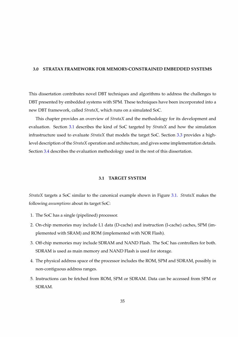
3.0 STRATAX FRAMEWORK FOR MEMORY-CONSTRAINED EMBEDDED SYSTEMS
This dissertation contributes novel DBT techniques and algorithms to address the challenges to
DBT presented by embedded systems with SPM. These techniques have been incorporated into a
new DBT framework, called StrataX, which runs on a simulated SoC.
This chapter provides an overview of StrataX and the methodology for its development and
evaluation. Section 3.1 describes the kind of SoC targeted by StrataX and how the simulation
infrastructure used to evaluate StrataX that models the target SoC. Section 3.3 provides a high-
level description of the StrataX operation and architecture, and gives some implementation details.
Section 3.4 describes the evaluation methodology used in the rest of this dissertation.
3.1 TARGET SYSTEM
StrataX targets a SoC similar to the canonical example shown in Figure 3.1. StrataX makes the
following assumptions about its target SoC:
1. The SoC has a single (pipelined) processor.
2. On-chip memories may include L1 data (D-cache) and instruction (I-cache) caches, SPM (im-
plemented with SRAM) and ROM (implemented with NOR Flash).
3. Off-chip memories may include SDRAM and NAND Flash. The SoC has controllers for both.
SDRAM is used as main memory and NAND Flash is used for storage.
4. The physical address space of the processor includes the ROM, SPM and SDRAM, possibly in
non-contiguous address ranges.
5. Instructions can be fetched from ROM, SPM or SDRAM. Data can be accessed from SPM or
SDRAM.
35
ScratchpadMemory(SRAM)
ROMCPU
FlashCntrl
I/OCntrl
SDRAMCntrl
ASIC
L1D$
MainMemory
(SDRAM)
On-chip Communications
L1I$
Storage(NAND Flash)
Figure 3.1: Example target SoC
6. Application binaries (including shared libraries) are compiled for the SoC’s ISA and stored in
off-chip NAND Flash, which is accessed through a file system.
7. An OS hosts the StrataX framework and relinquishes full control of the SPM to it.
8. The OS services I/O requests made by StrataX and the applications running under StrataX’s
control.
9. No application runs on the host OS outside the control of StrataX.
10. The OS provides virtual memory. The SPM is mapped at the same virtual address in all pro-
cesses.
11. A process consists of a single thread running on its own virtual address space. There is no
communication between processes. The OS schedules the processes.
12. StrataX replaces the system loader. It is mapped at the same virtual address in all processes.
All memory allocated by StrataX is shared by all processes.
36
3.2 SYSTEM-ON-CHIP SIMULATOR
A simulator of the target SoC is built to help in the implementation and evaluation of StrataX.
The simulator is an extension of the SimpleScalar [6] tool set. SimpleScalar for StrataX models the
target SoC. The simulated ISA is an extended version of SimpleScalar’s Portable Instruction Set
Architecture (PISA), which is similar to MIPS [50]. MIPS is used in embedded systems such as
game consoles (e.g., Sony’s Play Station Portable), networking devices and multimedia devices.
This section describes the moodifications made to SimpleScalar v3.0d1 to support StrataX.
3.2.1 Dynamic code generation
In the original simulator, all instructions are overwritten when the program is loaded. The sim-
ulator replaces the opcode field with an index for accessing its internal arrays. This pre-decoding
speeds up simulation, but prevents dynamic code generation. Unless the translator is aware of
pre-decoding, it will fail to correctly decode an instruction fetched from simulated memory. Also,
dynamically generated code may have to be created using the replacement indexes rather than
the original opcodes. Thus, a DBT system might become unnecessarily tied to the simulator. To
address this issue, the simulator is modified to perform instruction decoding on-the-fly, i.e., the
opcode is replaced by an index only when an instruction is fetched by the simulator. Thus, no
changes are made to the instructions in simulated memory, and the internal decoding becomes
invisible to the DBT system. A similar technique is used in Dynamic SimpleScalar [57] to enable
support for running a JVM on the PowerPC port of SimpleScalar. Huang et al. [57] report that
decoding each instruction on-the-fly is 30% faster than pre-decoding entire code pages the first
time they are accessed.
The SimpleScalar simulators do not maintain data in the simulated hardware caches. Any store
is immediately visible in main memory (i.e., the simulated caches are write-through). This is not a
problem for functional simulation, but leads to incorrect timing results when running a program
under DBT and simulating write-back caches. In a real system with separate data and instruction
caches, modified instructions go through the data cache before becoming visible in main memory,
just like any store. Before the modified instructions can be executed, they must be written-back to
main memory from the data cache, and their addresses invalidated from the instruction cache.
1http://www.simplescalar.com
37

0x00300000
0x00000000
0x00100000
0x00200000
0x00400000
I-SPM
D-SPM
VM code & data
mmap code
app. code
0x10000000
0x10000000
app. data
heap
stack
mmap data
args+environ0x7ffc0000
0x40000000
Figure 3.2: SimpleScalar address space use
MIPS provides a system call, called cacheflush , that can be used to synchronize the hard-
ware caches after dynamically generating or modifying code. The parameters of this system call
include the address range to be invalidated and which hardware cache (instruction, data or both)
to flush. This call is added to the simulator to be used by StrataX.
3.2.2 Dynamic memory allocation
Figure 3.2 shows how the virtual memory address space is used in the modified SimpleScalar.
Addresses below 0x004000000 are not used in the original simulator, so they can be used for the
SPM and StrataX. Linking and loading StrataX outside the address range used by programs lets
the original text segment to be fully shadowed so the translator can “fetch” an instruction using
its original virtual address.
The original Strata uses the mmapsystem call to allocate memory for the F$ and its data struc-
tures (e.g., fragment descriptors). Strata is linked to the translated program as a library, so it cannot
use a user-level memory allocation routine (e.g., malloc ) because the routine itself may be under
translation. The translator is likely to corrupt the internal state of any translated routine by calling
it during translation.
mmapis not implemented in the original SimpleScalar simulators. A partial implementation
that supports only anonymous mappings – i.e., mapping a page of zeroes without an underlying file
38

– is enough to provide StrataX with dynamic memory allocation without corrupting the translated
program’s data.
Executable pages are allocated by mmapbetween the end of the original program’s text (code)
segment and the beginning of the (static) data section (address 0x10000000 ), because the original
SimpleScalar simulator prevents execution from outside the text segment. Non-executable (i.e.,
data) pages are allocated starting at a reserved address after the heap, and growing towards the
stack.
Enforcing the access protections indicated in an mmapcall is not mandatory for simulating ap-
plications that do not need page protection. However, it is useful when debugging StrataX to use
appropriate page protection for the fragment cache, StrataX data structures, and original appli-
cation code and data. For instance, when StrataX is building a fragment, the original application
code and data should be write-protected as any write to them indicates a bug in StrataX.
3.2.2.1 SPM simulation Addresses between 0x00100000 and 0x00300000 are reserved in
the simulator for the instruction and data SPMs, as shown in Figure 3.2. The simulator has options
to specify the size of the instruction and data SPMs.
The reserved address range facilitates classifying memory operations in order to determine
their access latency. If the accessed address belongs to the SPM, the access latency is the same of
a L1 cache hit. Otherwise, the access is assumed to go to main memory through the hardware
caches (if present).
Application programs executed on the simulator need a mechanism to allocate SPM mem-
ory. The implementation of the mmapsystem call in the SoC simulator provides a custom flag,
MAPSCRATCHPAD, to indicate that an SPM address must be returned.
The simulator also includes extensions to collect and report SPM-related statistics, such as the
number of instructions executed from SPM, and the number of cycles spent executing code fetched
from SPM.
3.2.3 NAND Flash simulation
The SimpleScalar simulators use interpretation to run application level programs. UNIX system
calls are emulated with help from the host OS. Only user level cycles are counted by the original
timing simulator but in the evaluation of StrataX it is necessary to model NAND Flash access time.
39

Thus, SimpleScalar’s I/O system calls are modified to support NAND Flash storage simula-
tion:
• The open system call is overloaded to recognize a special path (/media/card ) as the mount
point of a NAND Flash storage device. In this way, the simulator can keep track of any file
descriptor that refers to a file in NAND Flash.
• Other system calls that take a file descriptor as an argument, such as read , are overloaded
to have a special behavior for files in NAND Flash. For debugging purposes and to simplify
simulation, it is assumed that the NAND Flash device is accessed through a read-only file
system.
• Direct access to the NAND Flash device is simulated when files are opened with the O DIRECT
flag. Direct access requires offsets passed to read and lseek system calls to be aligned to the
device’s page size. The default NAND Flash page size is 512 bytes but it can be set to a different
value with a configuration option. Direct access to NAND Flash files allows StrataX to bypass
OS buffering and perform its own buffering for code and data pages read from NAND Flash.
The simulator counts the number of accesses to NAND Flash through the read system call
and the number of NAND Flash pages read. For timing purposes, a fixed latency is added to the
simulator’s total cycle count each time a NAND Flash page is read. The number of cycles spent
in accessing NAND Flash, and the number of NAND Flash page reads are reported. Options for
configuring the page size of the simulated NAND Flash device and the read latency of a NAND
Flash page are provided by the SoC simulator.
Asynchronous I/O is also supported for the simulated NAND Flash storage device through a
set of system calls similar to standardized POSIX calls. aio read requests an asynchronous read.
An asynchronous read request takes the same number of cycles to complete as a synchronous
read, and starts after all pending asynchronous reads are completed. However, the timing model
is modified so instruction execution continues while the asynchronouous I/O requests are pro-
cessed. aio error and aio return are used by StrataX to poll the NAND Flash device and determine
whether an asynchronous I/O request has finished. The SoC simulator performs the actual read
from the host machine disk during the cycle when the simulated asynchronous read completes.
40
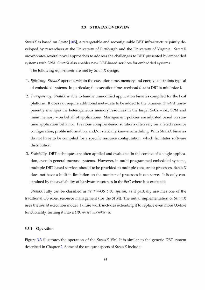
3.3 STRATAX OVERVIEW
StrataX is based on Strata [105], a retargetable and reconfigurable DBT infrastructure jointly de-
veloped by researchers at the University of Pittsburgh and the University of Virginia. StrataX
incorporates several novel approaches to address the challenges to DBT presented by embedded
systems with SPM. StrataX also enables new DBT-based services for embedded systems.
The following requirements are met by StrataX design:
1. Efficiency. StrataX operates within the execution time, memory and energy constraints typical
of embedded systems. In particular, the execution time overhead due to DBT is minimized.
2. Transparency. StrataX is able to handle unmodified application binaries compiled for the host
platform. It does not require additional meta-data to be added to the binaries. StrataX trans-
parently manages the heterogeneous memory resources in the target SoCs – i.e., SPM and
main memory – on behalf of applications. Management policies are adjusted based on run-
time application behavior. Previous compiler-based solutions often rely on a fixed resource
configuration, profile information, and/or statically known scheduling. With StrataX binaries
do not have to be compiled for a specific resource configuration, which facilitates software
distribution.
3. Scalability. DBT techniques are often applied and evaluated in the context of a single applica-
tion, even in general-purpose systems. However, in multi-programmed embedded systems,
multiple DBT-based services should to be provided to multiple concurrent processes. StrataX
does not have a built-in limitation on the number of processes it can serve. It is only con-
strained by the availability of hardware resources in the SoC where it is executed.
StrataX fully can be classified as Within-OS DBT system, as it partially assumes one of the
traditional OS roles, resource management (for the SPM). The initial implementation of StrataX
uses the hosted execution model. Future work includes extending it to replace even more OS-like
functionality, turning it into a DBT-based microkernel.
3.3.1 Operation
Figure 3.3 illustrates the operation of the StrataX VM. It is similar to the generic DBT system
described in Chapter 2. Some of the unique aspects of StrataX include:
41

Heterogeneous Code Cache
NO
YES
Init &Create Tasks
NewPC
Cached?
Finished?Link
Fragment
RestoreContext
SaveContext
NewFragment
StrataX VM
Fetch
Next PC
Decode
Translate &Instrument
Builder Loop
YES
NO
Make Room inCode Cache
ReorganizeCode Cache
Overflow?
NO
DeleteTask
HOT
Victim?Restore
FragmentYES
NO
Dispatch
EXIT
YES
YIELD
System-on-Chip
BUILD
NextTask
Control flow
Data access
Multi-tasking
SharedLibraries
ApplicationBinaries
Figure 3.3: StrataX Virtual Machine
42

System-on-Chip
Binaries (Apps.+Libs.)
Target Specific Functions
Host OS
Target Interface
Mem. Mngr.
F$ Mngr. Builder
Linker Stats
WatcherCtxt. Mngr. Fetcher
Logger
StrataX VM
Configuration Parser
Figure 3.4: StrataX Architecture
• When looking up a fragment, StrataX checks also its Victim Fragment Cache (VF$) (if enabled)
and if found, it restores (decompresses) the fragment rather than retranslating it fron NAND
Flash storage.
• The “fetch” step in the builder loop is overloaded to access application binaries and shared
libraries from NAND Flash storage (through the host OS). This step can perform incremental
loading and demand paging for code.
• When StrataX runs out of room in the F$ for new translated code, it manages the F$. StrataX’s
F$ can be allocated only to SPM, or extended across SPM and main memory forming a HF$.
When the SPM overflows, fragments can be discarded (as in traditional F$ management), com-
pressed into the VF$, or demoted to the HF$, depending on a specified policy.
3.3.2 Architecture
To facilitate retargetability, StrataX is divided in a target-independent part and a target-dependent
part, which communicate through a well-defined target interface. This is the same approach orig-
inally used in Strata [105]. The target-independent portion of StrataX is organized into several
modules, shown in Figure 3.4. The three modules on the left perform management tasks: applica-
tion contexts, F$ and host memory used for StrataX’s internal data structures. The three modules
43

in the center are used for accessing original code (fetcher), translating it (builder) and doing frag-
ment linking and unlinking (linker). The modules on the right hand side of the figure provide
services to the developers and users of StrataX.
The Context Manager maintains the execution state of the translated code and controls con-
text switching. The Fragment Cache Manager handles F$ overflows and provides the functional-
ity needed for managing the F$: memory allocation, re-sizing, fragment deletion, relocation and
compression/decompression. The Memory Manager provides an arena-based memory allocator
for StrataX’s data.
The Fetcher allows getting an instruction from an image of the untranslated code, which could
be in main memory or stored in an external device as a file. The Builder decodes and translates
instructions, and has a configurable policy for deciding when to stop a fragment. The Linker keeps
track of exit stubs and provides fragment linking and unlinking.
The Logger module helps in debugging StrataX by printing warnings, errors and information
about the translation process. The Stats module collects statistics about the translation process
(e.g., how many fragments are created, how many instructions are emitted into the F$, etc.) and
reports it at the end of the execution. These two modules are conditionally compiled into StrataX,
so they can be easily removed from a version of StrataX build for performance evaluation. Their
use is mostly in debugging and profiling the translator. The Watcher module is used to track
function calls and system calls of interest, and possibly handling them specially in the transla-
tion. It provides a system-call interposition mechanism that can be used to implement security
measures [104].
The configuration parser, shown on top of the modules, is StrataX’s “user interface” and allows
configuring it for enabling DBT-based services.
3.3.3 Approaches
This subsection gives an overview of the approaches used in StrataX to address the challenges to
DBT in embedded systems. The next chapter studies them in detail.
3.3.3.1 Bounded fragment cache StrataX reduces DBT’s memory overhead by eliminating du-
plication due to application’s code shadowing and bounding the size of the F$.
StrataX has loader-like capabilities to directly access code in external NAND Flash storage on-
44
demand. This service, called incremental loading, eliminates the need to shadow the entire text
segment. Incremental loading requires StrataX to be implemented as a stand-alone executable,
unlike Strata, which is linked to applications as a library. During execution, the translator accesses
the application binary as a file. On initialization, only the application’s static data needs to be
loaded. Code is loaded as translation progresses, following the program’s execution path.
The fast SPM is exploited in StrataX to amortize DBT’s performance overhead. This is accom-
plished by placing the F$ on the SPM. Thus, the capacity of the F$ is initially limited by the size of
the SPM. Such bounded F$ is likely to suffer frequent overflows and needs careful management
to achieve the best performance [49]. Bounding the size of the F$ also reduces the amount of main
memory required by data structures associated with the F$ (e.g., the fragment map).
3.3.3.2 Translated code footprint reduction StrataX also includes novel techniques that deal
with code expansion under DBT. Code expansion is due to the insertion of additional code for DBT
purposes in the translated code, which increases the size of the translated code with respect to the
original, untranslated code. It is also due to code duplication aimed at improving the performance of
translated code, and speculative translation (of code that may never be executed) aimed at reducing
the frequency of context switching.
A DBT system introduces additional code to stay in control of program’s execution. For in-
stance, exit stubs for direct CTIs and indirect branches are usually inlined within the translated
code to minimize dynamic instruction count. However, inline exit stubs often leave unused holes
in the F$ after fragment linking. The inlining of indirect branch handling code is often another
source of code duplication.
StrataX uses novel techniques to minimize the amount of F$ space used by exit stubs and other
forms of control code. It trades a possible increase in dynamic instruction count by a significant
reduction in the frequency of F$ overflows. By allowing actual application code rather than control
code to occupy most of the F$, StrataX reduces the frequency of F$ overflows. Thus, there is less
need for evicting code from the F$ and premature evictions are less likely.
DBT systems often employ a specific strategy to guide fragment formation. This kind of strat-
egy in general-purpose systems aims at improving code locality and reducing dynamic instruc-
tion count [52]. To that end, these strategies are likely to create duplicated and dead code. Several
fragment formation strategies are studied with StrataX and one is chosen that minimizes code
expansion for F$s in embedded systems.
45
The footprint reduction techniques in StrataX are complementary to existing F$ management
policies[12, 48, 49], which are focused in choosing which code to preserve and which code to
discard.
3.3.3.3 Fragment cache management The cost of fetching instructions from external NAND
Flash may be high in both execution time and energy consumption. To alleviate this cost, StrataX
uses a form of victim caching [66] to reduce the number of NAND Flash accesses due to re-translation.
With a VF$, fragments are not immediately deleted upon eviction. Instead, they are kept in mem-
ory in a non-executable format. If a requested fragment is found in the VF$, it can be restored
to the main (executable) F$ with a lower cost than re-translating it from the NAND Flash device.
Frequently used fragments are pinned to the F$ to prevent their repeated eviction.
When the F$ is allocated only to the SPM, the VF$ actually takes the form of a transient Com-
pressed Victim Fragment Cache (CVF$). Victim fragments are stored at one end of the F$ in com-
pressed form, while translated code is emitted from the other end of the CVF$. Upon filling the
space un-occupied by the CVF$, the entire CVF$ is discarded and its space is made available to
newly translated code.
When the SPM is too small to contain the translated code working set of a program (or set of
program’s) executed under DBT control, StrataX allows extending the F$ across SPM and main
memory. This effectively creates a HF$. The host processor can fetch and execute code from
anywhere in the HF$.
StrataX incorporates techniques for adaptively resizing the HF$ to capture the translated code
working set, and also for effectively partitioning the translated code among SPM and main mem-
ory. Translated code should be placed in the HF$ in such a way that the number of off-chip memory
accesses made by the translated code is minimized. An effective HF$ management strategy amor-
tizes the overhead due to code re-location and deletion with an improvement in translated code
execution time.
3.3.4 Implementation
The first step in the development of StrataX was retargeting Strata to PISA. The Strata-PISA port
is based on the Strata-MIPS port [105], which was not optimized for embedded systems.
46

3.3.4.1 Translation Since SimpleScalar (SS) is a user-level simulator, PISA does not contain
MIPS privileged instructions. CTIs in PISA are similar to CTIs in MIPS. However, PISA does
not have branch delay slots (which cause the instruction following a branch to be executed regard-
less of the branch outcome) nor likely branches (which cause the instruction following a branch to
be executed when the branch is taken). The lack of these features simplifies the translation step in
StrataX.
Table 3.1 shows a few examples of how PISA instructions are translated depending on the
fragment formation policy in use. Non-CTIs are often just copied to the F$ (an IDENT translation),
unless the fragment becomes too large. CTIs must be handled carefully, since they are decision
points for the translator to decide whether to continue building the fragment or to terminate it,
and how to do so.
3.3.4.2 Fragment formation StrataX can be configured to use a variety of fragment formation
policies. These policies decide whether to stop fragment formation according to the characteris-
tics of the instruction being translated. Table 3.2 summarizes the possible choices for ending a
fragment on a CTI, specialized by instruction class:
• An instruction that is not used for control transfers (non-CTI) is never an ending point. Trans-
lation continues with the next instruction.
• Unconditional jumps have a statically known target that is always taken. The fragment can be
terminated or continued with the target address. Continuing with the target address elides the
jump.
• Conditional branches define two targets, which are statically known. The fragment can be
terminated at the conditional branch or, alternatively, translation may continue speculatively
down one path. Continuing with the target of the branch requires negating the branch condi-
tion.
• Direct calls are similar to conditional branches – they have a target and a fallthrough (the return
address). However, both paths are eventually executed. It is possible to emit the call’s target
address in a separate fragment or to partially inline the call target. The return address can be
used to continue the fragment if the target of the call target is not partially inlined.
• An indirect CTI always ends a fragment because its target address is unknown during transla-
tion.
47

Table 3.1: PISA instruction handling examples
Instruction class Translation choicesNon-CTI Copy (IDENT) and continuePC : add $rx,$ry,$rz f (PC ) : add $rx,$ry,$rz
Unconditional Jump Elide and continue with targetPC : j TPC f(PC) = f(TPC ) : ...
Link to target and stopf (PC ) : j f (TPC)
Stop with trampoline to targetf (PC ) : build(TPC)
Conditional Branch Stop with target and fallthrough trampolinesPC : beq $rx,$ry,TPC f(PC) : beq,$rx,$ry, f (PC)+64PC +8: ... f (PC)+ 8: build(PC+8)
f (PC)+64: build(TPC)Link to target and stop with fallthrough tramp.
f (PC) : beq,$rx,$ry, f (TPC)f (PC)+ 8: build(PC+8)
Link to target and continue with fallthroughf(PC) : beq,$rx,$ry, f (TPC)f (PC)+ 8 = f(PC +8) : ...
Direct Call Stop with target and return trampolinesPC : jal TPC f(PC) : jal f (PC)+64PC +8: ... f (PC)+ 8: build(PC+8)
f (PC)+64: build(TPC)Partially inline target
f (PC) : li $31 , ( PC+8)f (PC)+16 = f(TPC ): ...
Link to target and continue with return addressf (PC) : jal f (TPC)f (PC)+ 8 = f(PC +8) : ...
Return Fast returnPC : jr $31 f (PC): jr $31
Indirect Branch Stop with trampolinePC : jr $rt f (PC): build($rt )
48

Table 3.2: StrataX fragment formation options
Instruction class Stop condition Continue optionsNon-CTI - Never - Next addressUnconditional Jump - Never - Target address (elide)(Backwards/Forwards) - If target in F$
- AlwaysConditional Branch - Never - Fallthrough address(Backwards/Forwards) - If target in F$ - Target address
- If fallthrough in F$- If either in F$- If both in F$- Always
Direct Call - Never - Target address (inline)- If target in F$ - Return address- If return in F$- If either in F$- If both in F$- Always
Indirect CTI - Always
The decision to end a fragment on a CTI can be taken absolutely (always end or always con-
tinue) or it can consider whether the target fragment is in the F$. The choices could be further
specialized by the CTI’s direction (backwards or forwards) for branches and jumps.
Additionally, a limit might be set on the number of instructions fetched to build a fragment or
on the size of the fragment. Reaching that limit can be a reason to stop fragment formation, even
if the next instruction is not a CTI.
StrataX allows the creation of PC mappings, which are alternative entry points into a fragment.
They are implemented as special entries in the fragment map that associate an application address
with a F$ location that is not the first translated instruction in a fragment. PC mappings are
necessary for some of the choices to work. For instance, to stop a fragment on an unconditional
CTI when the target is already in the F$, or otherwise elide the CTI, the first elision must create a
PC mapping for the target address. Subsequent elisions can not be avoided otherwise.
3.3.4.3 Trampolines One of the main differences between Strata-MIPS and Strata-PISA is the
organization of code used for context switching (i.e., trampolines). In Strata-MIPS, it takes 78 or
84 instructions to perform a context switch [105], due to the large number (32) of general-purpose
49

registers. Strata-MIPS emits the code for saving all these registers in every trampoline. This design
leads to an excessive increase in translated code size. In Strata-PISA, an inline trampoline only
saves enough registers to be able to pass arguments to the translator. Then, it transfers control to
a shared routine that completes the context save and transfers control to the translator.
Strata uses a simple F$ layout in which fragments and trampolines are interleaved [8]. StrataX
can also place the trampolines in their own section of the F$, called a trampoline pool.
3.3.4.4 Fragment cache management Strata supports only demand FLUSH to handle F$ over-
flows. StrataX includes much richer support for manipulating the F$, which allows the imple-
mentation of several F$ management policies. Sections 5.2 and 5.3 describe the F$ management
policies implemented in StrataX.
F$ management operations in StrataX include:
• Creating a F$ composed of multiple units, called segments.
• Allocating F$ segments to the SPM.
• Adding F$ segments during execution.
• Increasing the size of a F$ segment if the memory after it is free.
• Deleting one or more fragments from the F$.
• Relocating one or more fragments from one F$ segment to another.
3.3.4.5 Fragment linking and unlinking When StrataX allocates fragments and trampolines
interleaved in the F$, trampoline generation can be avoided if the target fragment has already
been translated. Rather than emitting a trampoline, the fragment is directly linked to its target.
This pro-active fragment linking [45] saves F$ space when an unbounded F$ is used, and when F$
overflows are handled with FLUSH.
However, when using FIFO or Segmented FIFO, space must be reserved to change the link into
a trampoline if the target fragment gets deleted. This issue is illustrated in Figure 3.5. The figure
shows translated code before and after removing fragment Fa. The branch in Fb is redirected to
the target fragment iff the offset is small enough to be encoded in the signed 16-bit immediate field
(i.e., ≤128K for PISA), otherwise the branch is redirected to the trampoline and the trampoline is
overwritten with a jump to the target fragment.
50

Fa:
beq $rx,$ry,
j Fc
Fb:
Fc:
(reserved)
Fa beq $rx,$ry,
j Fc
Fb:
Fc:
T:(trampoline)
T
......
...
Figure 3.5: Fragment unlinking
3.3.4.6 System call handling Some system calls require special handling, which is implemented
using StrataX’s system call interposition mechanism.
The logger and statistics modules in StrataX by default use the standard error to print mes-
sages. In general, a close system call must not affect file descriptors used by StrataX. A wrapper
function replaces close in the translated code to ensure that StrataX’s files remain open. In Strata,
wrapper functions are translated into the F$. In StrataX, they are just called out to avoid wasting
precious F$ space.
Self-modifying code in MIPS can be detected by the presence of a cacheflush system call. If
found, a cacheflush system call is replaced with a trampoline that invokes the translator to
deal with the modified code. Translated code for the addresses in the cacheflush call must be
invalidated from the F$.
Programs use the exit system call to communicate their finalization to the OS. The exit
system call must also be intercepted to let StrataX handle process termination.
51

Table 3.3: PXA270 SimpleScalar Configuration
Parameter ConfigurationFrequency 624 MhzFetch queue 8 entriesBranch predictor bimodal, 4 cycle mispred. penaltyBranch target buffer 512 entries, 4-way set-associativeFetch/decode width 1 instr./cycleIssue 1 instr./cycle, in orderFunctional units 1 IALU, 1 IMULT, 1 FPALU, 1 FPMULTRUU capacity 4 entriesIssue/commit width 2 instr./cycleLoad/store queue 4 entriesMemory page size 4 KBTLBs 32 entries, fully-associative, 30 cycle missL1 D-cache 32 KB, 32-way, FIFO, 1 cycleL1 I-cache 32 KB, 32-way, FIFO, 1 cycleBus width 8 bytesMain memory latency 60 cycles first chunk, 12 cycles rest
3.4 EXPERIMENTAL METHODOLOGY
The techniques and approaches in StrataX are evaluated experimentally by executing embedded
programs on the simulator, both natively and under control of StrataX with different configu-
rations. The programs come from MiBench [46], a benchmark suite representative of embedded
applications. All but two of the programs in the suite can be executed in the simulated SoC, with
their large input data sets2.
The simulator is configured in the experiments in this dissertation to model three different
embedded processors:
• Intel/Marvell 624MHz XScale PXA-270 [62], configured as shown in Table 3.3.
• ARM926EJ-S [62], configured as shown in Table 3.4.
• ARM1176EJ-S [62], configured as shown in Table 3.5.
All the processors have a relatively simple, in-order pipeline. The SPM access time is one cycle,
just like the L1 caches. The PXA-270 caches are 32-way set-associative, while the ARM caches are
4-way. The model used for each experiment is indicated when discussing the results.
2The programs that do not run are madand sphinx , which do not even compile with the SimpleScalar toolchain.
52

Table 3.4: ARM926 SimpleScalar Configuration
Parameter ConfigurationFrequency 100 MhzFetch queue 4 entriesBranch predictor not taken, 2 cycle mispred.penaltyFetch/decode width 1 instr./cycleIssue 1 instr./cycle, in orderFunctional units 1 IALU, 1 IMULT, 1 FPALU, 1 FPMULTRUU capacity 4 entriesIssue/commit width 1 instr./cycleLoad/store queue 4 entriesMemory page size 4 KBTLBs 64 entries, 2-way, 10 cycle missL1 D-cache 8 KB, 4-way, LRU, 1 cycleL1 I-cache 4 KB, 4-way, LRU, 1 cycleBus width 4 bytesMain memory latency 10 cycles first chunk, 4 cycles rest
A major difference between MIPS and PISA is that the former uses 32-bit encoding for instruc-
tions, while the latter uses 64-bit encoding in order to facilitate experimentation. For instance,
PISA reserves 16 of the 64 bits for annotations. PISA has 32 registers, but register fields are 8-bit
long rather than 5-bit long. This makes it simple to increase the number of general-purpose reg-
isters in the simulated processor. StrataX can store both data and instructions in the F$, but since
instructions are 64-bit, a 32-bit word of data stored in the F$ occupies an entire instruction slot,
i.e., it uses the lower 32 bits and leaves the higher 32 bits unused.
To account for the 64-bit instruction size, cached instruction addresses are divided by 2 using
a simulator option. The sizes of the SPM and the F$ are doubled since they contain instructions.
In the discussions, the effective size is used rather than the simulated size, i.e., a 16K SPM is
simulated with 32K but referred as 16K in the evaluation.
To get access times for the Flash memory, measurements were made on a Dell Axim x50v
PocketPC with NOR Flash and a 8192-byte file buffer. On this device, it takes the operating system
(Windows Mobile Edition 5) 1.6ms to initially fetch a block into the file buffer from Flash memory
and 67,700ns per word to read from the block.
Reading a page from a binary in NAND Flash storage requires going through the file system
and FTL, so the cost can be relatively high. According to experiments done by Ajwani et al. [3],
53

Table 3.5: ARM1176 SimpleScalar Configuration
Parameter ConfigurationFrequency 400 MhzFetch queue 4 entriesBranch predictor bimodal, 4 cycle mispred. penaltyBranch target buffer 128 entries, direct-mappedReturn stack 3 entriesFetch/decode width 1 instr./cycleIssue 1 instr./cycle, in-orderFunctional units 1 IALU, 1 IMULT, 1 FPALU, 1 FPMULTRUU capacity 8 entriesIssue/commit width 2 instr./cycleLoad/store queue 4 entriesMemory page size 4 KBL1 D-cache 16 KB, 4-way, FIFO, 1 cycleL1 I-cache 16 KB, 4-way, FIFO, 1 cycleBus width 4 bytesMemory latency 36 cycles first, 4 cycles rest
the bandwidth for reading a 512-byte NAND Flash page from a Kingston 1GB CompactFlash
card is 0.6 MB/s, regardless of the access pattern (sequential or random). Thus, the simulator’s
cycle count is increased on a NAND Flash page read by the corresponding cost. The page size is
doubled in simulation to account for the 64-bit instruction size, so the cost of reading a data page
is also doubled.
Simulation offers flexibility and facilitates carrying out experiments to determine sources of
overhead. The SimpleScalar extensions for StrataX include additional counters for cycles, instruc-
tions and other events that are incremented according to the source of the executing instruction
(i.e., SPM, text segment or dynamically generated code). The figures in this dissertation often
show a breakdown of a program’s execution time to make it easier to determine sources of over-
head. The breakdown may include data load cost, code load cost, translation time (number of
cycles spent executing StrataX code), and translated code execution time split into execution from
main memory or from the SPM.
54

4.0 CODE GENERATION
This chapter studies several code generation techniques to effectively exploit the fast but small
SPM to hold the F$ in a DBT system. The chapter is organized as follows. Section 4.1 studies the
performance impact of allocating the F$ to SPM prior to the application of StrataX’s techniques.
Section 4.2 compares several fragment formation strategies to choose one that performs well on
a small F$. Section 4.3 presents techniques to minimize the amount of code introduced by a DBT
system to keep control of program execution.
4.1 PERFORMANCE OF SMALL FRAGMENT CACHES
To motivate the techniques in this chapter, the performance impact of constraining the F$ size and
allocating it to the SPM is analyzed. For this study, StrataX is used to execute MiBench programs
under DBT on a simulated PXA-270 SoC with NOR Flash. The I-cache capacity is scaled to match
the size of a SPM. In experiments with SPM, there is no I-cache. Three cases are considered. The
first case is a baseline. It has no SPM, but it does have an L1 I-cache. Programs are executed
natively, i.e., without StrataX. In the second case, programs are executed under DBT with a F$
in main memory. The F$ in the second case is large enough (2MB) to hold the translated code
working set of any MiBench program without suffering from F$ overflows. The third case uses
SPM and there is no I-cache. The SPM size is varied from 16KB to 64KB. The F$ occupies the whole
SPM. In SPM configurations, StrataX’s instructions are fetched from ROM without the benefit of
an I-cache, i.e., StrataX’s binary image is not cached. ROM has a 1-cycle access in those cases.
StrataX’s data structures are in SDRAM. The translated binary program is incrementally loaded
by StrataX into the F$ when DBT is used.
Figure 4.1 shows the impact of constraining the F$ size. The graph reports speedup normalized
55

Figure 4.1: Speedup relative to native execution for a 2MB fragment cache in SDRAM; and frag-
ment caches in 64KB, 32KB and 16KB SPM with FLUSH
to executing a program natively with memory shadowing. The baseline includes the shadowing
cost. Some results do not show in the graph; these cases have no speedup and can suffer large
slowdowns. We discuss the most interesting cases in the text. The first bar (“Mem-2MB”) gives
the speedup when the programs are run with StrataX, the 2MB F$ is in SDRAM and the I-cache is
32KB.
Programs can run faster with StrataX, despite overhead imposed by DBT. For example, jpeg-
decode has 3.2 speedup with StrataX. This improvement is due to incremental loading because
only a small portion of the binary image is actually exercised. With StrataX, only the code that is
executed is loaded into the F$, which leads to fewer accesses to Flash memory. As a result, less
time is spent loading the program, which can be more easily amortized. There are three programs,
basicmath, fft and gsm-encode, where performance suffers with StrataX. basicmath has a 44.9% per-
formance degradation, fft has a 6% degradation, and gsm-encode has a 15.7% degradation. Because
these programs are small, their binary image can be loaded quickly with memory shadowing. As
a result, there is less benefit from incremental loading. Also, memory shadowing does not incur
the overhead of DBT.
56

The remaining bars (“SP-64KB”, “SP-32KB”, and “SP-16KB”) show the speedup when the F$
is in SPM. These results are normalized to a baseline with an I-cache that has the same capacity
as the SPM. The results show that when the SPM is large enough (e.g., SP-32KB), many programs
(e.g., crc32, gsm-decode, quicksort, sha, stringsearch, and susan-smoothing) have similar performance
as Mem-2MB. In this situation, the translated code’s working set fits in SPM. In essence, SPM
serves the same role as the I-cache. In a few cases, performance is improved. For example, adpcm-
encode goes from a 1.7x speedup with Mem-2MB to a 1.9x speedup with SP-64KB and SP-32KB.
This improvement is due to the faster effective access time with SPM and illustrates the benefit of
placing the F$ in SPM, rather than main memory.
However, when the translated code’s working set does not fit in SPM, performance suffers.
In rijndael-encode, the speedup decreases from 1.9x (SP-64KB) to 1.7x (SP-32KB). This degradation
is more pronounced when going from SP-32KB to SP-16KB, where SP-16KB has 81.5x slowdown.
gsm-decode has particularly dramatic behavior: its performance goes from a 1.8x speedup (SP-
64KB) to a 491.2x slowdown (SP-16KB)! This benchmark thrashes badly with a small F$.
The reason some programs do worse with a small F$ is due to the F$ management policy. A
typical strategy, FLUSH, handles F$ overflow by discarding the entire contents of the F$ [8]. Too
many flushes lead to poor performance. Table 4.1 shows the number of flushes for each SPM size.
The programs usually have zero or one flushes for SP-64KB. When SPM is 32KB or 16KB, there
can be many more flushes. For example, gsm-encode has one flush in SP-64KB, 10,862 flushes in
SP-32KB, and 26,162 flushes in SP-16KB.
These results show that flushing and subsequently refilling the F$ can harm performance.
There are two parts to this problem. First, the cost of fetching an untranslated instruction is high
due to Flash memory. Even with file buffers, Flash memory has a high effective access latency.
Second, the number of flushes is important, given the latency of reading instructions from Flash
memory.
The performance of a small F$ can be improved by reducing the frequency of F$ overflows
and their handling cost. Reducing the number of overflows is similar to minimizing the miss rate
in traditional hardware caches because a decrease in overflows leads to fewer premature evictions
and overall F$ misses. Likewise, the cost of refilling the F$ and loading code from Flash is similar
to the miss penalty. StrataX uses footprint reduction to minimize the amount of code generated by
DBT so more of the working set can be captured in the small F$. With a small footprint, there
are fewer F$ overflows. Nevertheless, this reduction does not guarantee that the working set
57

will fit in the F$. StrataX reduces the penalty of re-translating prematurely evicted instructions by
memoizing them in a VF$. The memoized instructions can be accessed more quickly than the ones
in Flash. Lastly, StrataX uses fragment pinning to avoid unnecessary eviction and memoization of
frequently executed code. Essentially, StrataX reduces the miss rate and the miss penalty of a small
F$ so it can be allocated to SPM.
58
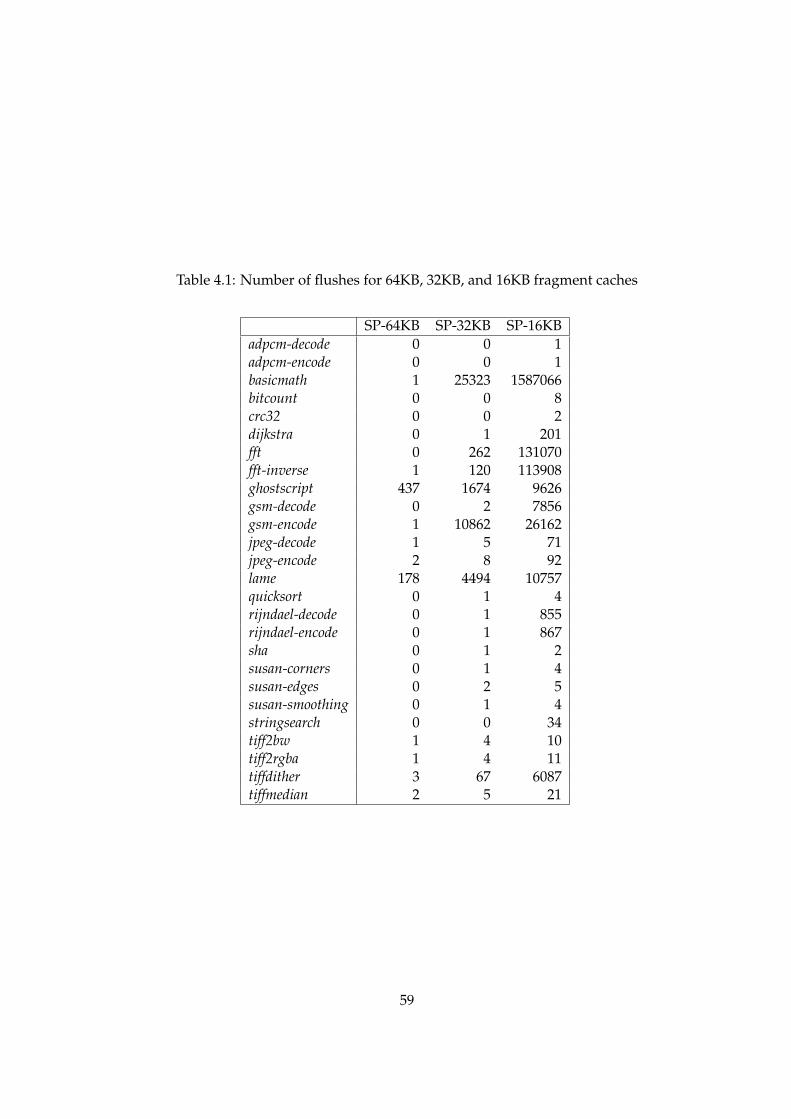
Table 4.1: Number of flushes for 64KB, 32KB, and 16KB fragment caches
SP-64KB SP-32KB SP-16KBadpcm-decode 0 0 1adpcm-encode 0 0 1basicmath 1 25323 1587066bitcount 0 0 8crc32 0 0 2dijkstra 0 1 201fft 0 262 131070fft-inverse 1 120 113908ghostscript 437 1674 9626gsm-decode 0 2 7856gsm-encode 1 10862 26162jpeg-decode 1 5 71jpeg-encode 2 8 92lame 178 4494 10757quicksort 0 1 4rijndael-decode 0 1 855rijndael-encode 0 1 867sha 0 1 2susan-corners 0 1 4susan-edges 0 2 5susan-smoothing 0 1 4stringsearch 0 0 34tiff2bw 1 4 10tiff2rgba 1 4 11tiffdither 3 67 6087tiffmedian 2 5 21
59

4.2 FRAGMENT FORMATION STRATEGY
Past DBT research for general-purpose systems has examined F$ management approaches that
effectively decide what code to keep in the F$ and when to discard it [8, 48, 49]. Also, how to resize the
F$ to acommodate the translated code working set [12] and how to maintain the contents of the
F$ consistent with the untranslated code [12]. Even with these techniques, the F$ can still grow to
hundreds of kilobytes to a few megabytes in size for general-purpose applications [49].
The footprint of the translated code has rarely been a concern. In general-purpose systems there
is often a performance benefit from code expansion when the F$ is unbounded [8, 52]. However,
in embedded systems with limited memory resources, the capacity of the F$ is an important con-
cern. Some DBT systems targeting devices with limited main memory have partially tackled this
problem [43, 44]. With a smaller translated code footprint, there is less pressure on the F$, and its
miss ratio is improved.
The first step in reducing the footprint of translated code is to configure StrataX’s fragment
formation policy for a small F$. In this section, several fragment formation strategies are experi-
mentally compared to choose one that performs well with a small F$ allocated to SPM.
DBT follows the execution path and translates instructions as they are needed, i.e., on-demand.
A sequence of translated instructions forms a fragment. Fetching and translating a CTI offers an
opportunity to decide whether to stop forming a fragment. Continuing a fragment beyond a CTI
may help avoid a context switch between the translator and the F$ and also form a larger region
for potential dynamic optimizations. There are often several choices, which affect code footprint,
and ultimately, performance.
When fragment formation is continued at a direct CTI, duplicate translated code is created. If
the target of the direct CTI was already in the F$, it will be duplicated (inlined) in the currently
translated fragment. In general-purpose systems, this reduces the instruction count and helps
instruction locality. However, this approach increases the translated code footprint and the possi-
bility of F$ overflows in a bounded F$.
Other configuration choices lead to dead translated code. This situation happens when a target
of a conditional CTI is speculatively translated but the condition to execute it never occurs before
a F$ overflow or the end of execution. Continuing fragment formation at the return address of
a call has a similar problem. In this case, the called procedure may not fit in the F$, causing an
overflow. The F$ management policy used to handle the overflow may evict the translated code
60

Table 4.2: Evaluated fragment formation strategies
DBB Original Strata Optimized Strata LREUnconditional Always stop Always continue If target cached, If target cached,Jump (fallthrough) stop, else elide stop, else elideConditional Always stop Always stop Always continue Always continueBranch (fallthrough) (fallthrough)Direct Call Always stop Always inline Always stop Always continue
(return address)
for the return address before the called procedure returns.
StrataX supports multiple configuration choices for handling each kind of CTI. Since exploring
all possible combinations would require too much time and space, only four strategies already
used by state-of-the-art DBT systems are evaluated. The strategies are described in Table 4.2:
• dynamic basic block (DBB) [110] is a configuration where fragments are terminated at every CTI,
so they correspond to dynamically constructed basic blocks. A similar strategy is used in the
VMWare dynamic binary translator [2].
• Original Strata is Strata’s original fragment formation strategy [105]. It is similar to the strategy
used to form “basic blocks” by DynamoRIO [17]. Fragments are stopped only when the target
of a CTI is unknown at runtime. This is the strategy used in the initial experiments in this
chapter.
• Optimized Strata is a strategy devised to minimize the dynamic instruction count, but it was
originally developed with an unbounded F$ [52].
• Least Redundant Effort (LRE) is the strategy used by HDTrans [111], which attempts to maximize
reuse of translation effort.
For the evaluation, the best techniques to reduce control code size described later in Section 4.3.
F$ overflows are handled with the FLUSH policy, but similar trends are expected with FIFO or
other F$ management policies. The fast returns [105] mechanism is turned off in StrataX because
any F$ return address on the stack makes it impossible to evict the corresponding fragment (unless
a fixing mechanism is used maintain correctness).
Figure 4.2 shows the slowdown for the last three configurations, relative to DBB, with a 32K F$.
The Original Strata configuration sometimes achieves performance close to DBB, but it is generally
not as good. On average, it adds a performance overhead of 19%. In some cases it is almost
61

0
1
10
100
1000
10000
Slo
wdo
wn
vs. D
BB
(F
LUS
H)
Orig-Strata Opt-Strata LRE
adpc
m.d
ecad
pcm
.enc
basi
cmat
hbi
tcou
ntbl
owfis
h.de
cbl
owfis
h.en
ccr
cdi
jkst
ra fftfft
.inv
ghos
tscr
ipt
gsm
.dec
gsm
.enc
ispe
lljp
eg.d
ecjp
eg.e
ncla
me
patr
icia
pgp.
dec
pgp.
enc
qsor
trij
ndae
l.dec
rijnd
ael.e
nc sha
strin
gsea
rch
susa
n.co
rsu
san.
edg
susa
n.sm
otif
f2bw
tiff2
rgba
tiffd
ither
tiffm
edia
nty
pese
tA
vera
ge
0.00
0.25
0.50
0.75
1.00
1.25
1.50
1.75
2.00
Slo
wdo
wn
vs. D
BB
(F
LUS
H)
11309.6
Figure 4.2: Slowdown relative to DBB for evaluated fragment formation strategies
62

adpc
m.d
ecad
pcm
.enc
basi
cmat
hbi
tcou
ntbl
owfis
h.de
cbl
owfis
h.en
ccr
cdi
jkst
ra fftfft
.inv
ghos
tscr
ipt
gsm
.dec
gsm
.enc
ispe
lljp
eg.d
ecjp
eg.e
ncla
me
patr
icia
pgp.
dec
pgp.
enc
qsor
trij
ndae
l.dec
rijnd
ael.e
nc sha
strin
gsea
rch
susa
n.co
rsu
san.
edg
susa
n.sm
otif
f2bw
tiff2
rgba
tiffd
ither
tiffm
edia
nty
pese
tA
vera
ge
0%
20%
40%
60%
80%
100%
% D
upl.F
etch
s (F
LUS
H)
DBB Orig.Strata Opt.Strata LRE
Figure 4.3: Percentage of duplicated instruction fetches for different fragment formation strategies
equivalent (≤1% overhead) to DBB, e.g., bitcount and quicksort. For benchmarks like ispell and
typeset, the slowdowns over DBB are 3.55x and 2.35x. The Optimized Strata strategy significantly
increases the pressure on the F$, leading to performance degradation. bitcount has an overhead of
5%. Benchmarks like gsm-encode and patricia do not fit into the F$, and have slowdowns of 733.11x
and 8523.77x! LRE leads to similar problems. For instance, fft has a slowdown of 715.02x and
gsm-encode has a slowdown of 1009.56x relative to the performance achieved with DBB.
The increased F$ pressure can be attributed to an increase in duplicated and dead translated
code. The percentage of duplicated application instruction fetches is shown in Figure 4.3 for the
four policies with a 32K F$. These results consider duplication due both to fragment formation
policy and re-translation of prematurely evicted fragments. Although DBB has some duplication,
duplication is significantly larger with the other policies. For instance, bitcount needs 6.2% dupli-
cated fetches with DBB, 11.05% with Original Strata, 35.98% with Optimized Strata and 39.34%
with LRE. The effect on fft is more impressive. The percentages of duplicated fetches for fft are:
11.28% (DBB), 34.66% (Original Strata), 57.27% (Optimized Strata) and 99.98% (LRE).
The percentage of dead translated code is shown in Figure 4.4. It is a measure of wasted
translation effort, i.e., translating instructions that are evicted before execution. Some of this effort
is unavoidable, such as trampolines that must be emitted but are never taken. DBB is again the best
policy. For instance, in bitcount, 8.13% of the code generated with DBB is never executed, while
63
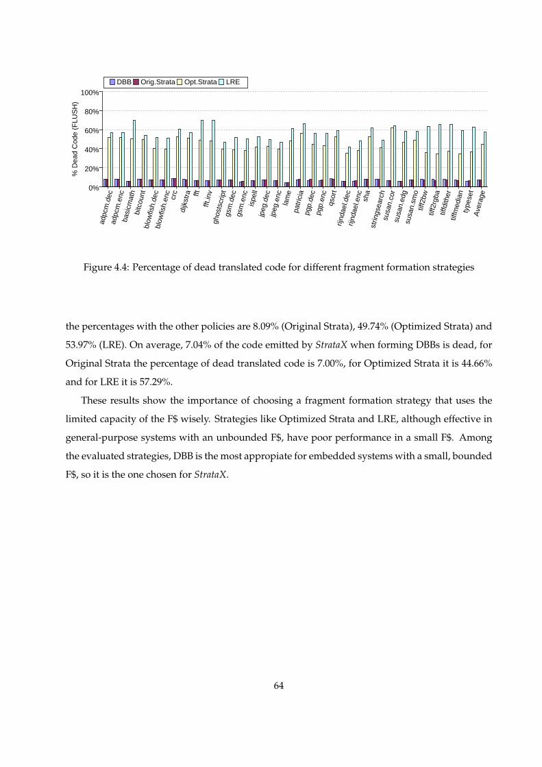
adpc
m.d
ecad
pcm
.enc
basi
cmat
hbi
tcou
ntbl
owfis
h.de
cbl
owfis
h.en
ccr
cdi
jkst
ra fftfft
.inv
ghos
tscr
ipt
gsm
.dec
gsm
.enc
ispe
lljp
eg.d
ecjp
eg.e
ncla
me
patr
icia
pgp.
dec
pgp.
enc
qsor
trij
ndae
l.dec
rijnd
ael.e
nc sha
strin
gsea
rch
susa
n.co
rsu
san.
edg
susa
n.sm
otif
f2bw
tiff2
rgba
tiffd
ither
tiffm
edia
nty
pese
tA
vera
ge
0%
20%
40%
60%
80%
100%
% D
ead
Cod
e (F
LUS
H)
DBB Orig.Strata Opt.Strata LRE
Figure 4.4: Percentage of dead translated code for different fragment formation strategies
the percentages with the other policies are 8.09% (Original Strata), 49.74% (Optimized Strata) and
53.97% (LRE). On average, 7.04% of the code emitted by StrataX when forming DBBs is dead, for
Original Strata the percentage of dead translated code is 7.00%, for Optimized Strata it is 44.66%
and for LRE it is 57.29%.
These results show the importance of choosing a fragment formation strategy that uses the
limited capacity of the F$ wisely. Strategies like Optimized Strata and LRE, although effective in
general-purpose systems with an unbounded F$, have poor performance in a small F$. Among
the evaluated strategies, DBB is the most appropiate for embedded systems with a small, bounded
F$, so it is the one chosen for StrataX.
64

4.3 CONTROL CODE FOOTPRINT REDUCTION
The second step in reducing the footprint of the translated code is to improve the utilization of
the F$ by minimizing the amount of code that StrataX inserts to maintain control over execution.
Better F$ utilization reduces the frequency of F$ overflows and the F$ miss rate, leading to a
significant performance improvement.
In this section, the contents of the F$ are categorized to distinguish those instructions neces-
sary to carry out the application behavior from those inserted by StrataX to maintain control over
execution. The relative F$ space consumed by each instruction category is measured to identify
which aspects of the “control code” have the largest impact on code footprint and develop tech-
niques to minimize it. Reducing the amount of F$ space consumed by “control code” leaves more
room for actual application code.
4.3.1 Translated Code Composition Without Footprint Reduction
The instructions emitted into the F$ can be classified according to their purpose. Figure 4.5 shows
an example of untranslated code (left side) and its corresponding translated code (right side). The
translated instructions in the figure are examples of each of the following categories.
Prologue instructions are executed to complete the context restore when returning from the
DBT to the translated code. In PISA, control is transferred to a fragment using an indirect jump
(see exec routine), which requires a free register. The register must be restored at the target
fragment. All fragments in Figure 4.5 (F1, F2, F4) have a prologue that restores the register with
the fragment address with its original application value: lw $ra,ra ofs($sp) .
Native instructions are copied from the binary to the F$ without modification or translated
for some purpose. In Figure 4.5, fragment F1 contains a series of native instructions (labelled
“Native”).
Trampoline instructions are used to return control to the DBT system when the target address
of a CTI is untranslated. Fragment F1 has trampolines at T1a and T1b , corresponding to the
branch’s taken and not-taken target application addresses. These target addresses are initially un-
translated. After F1 is executed, and the branch is taken, control returns to the DBT (see reenter
routine). Then, the DBT creates the target fragment F2 and fragment linking redirects the branch
in F1 to F2t , skipping the prologue. If the branch is taken again, execution stays in the F$.
65
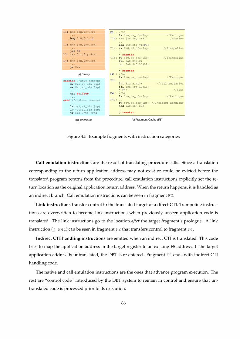
L1: xxx $rx,$ry,$rz...beq $t0,$t1,L2...
L2: xxx $rx,$ry,$rz...jal L4
L3: xxx $rx,$ry,$rz...
L4: xxx $rx,$ry,$rz...jr $ra
(a) Binary
reenter://save contextsw $ra,ra_ofs($sp)sw $at,at_ofs($sp)...jal builder...
exec://restore context...lw $a1,a1_ofs($sp)lw $a0,a0_ofs($sp)jr $ra //to frag
(b) Translator
F1 : //L1lw $ra,ra_ofs($sp) //Prologue
F1t: xxx $rx,$ry,$rz //Native...beq $t0,$t1,T1bF2t
T1a: sw $a0,a0_ofs($sp) //Trampoline...j reenter
T1b: sw $a0,a0_ofs($sp) //Trampolinelui $a0,HI(L2)ori $a0,$a0,LO(L2)...j reenter
F2 : //L2lw $ra,ra_ofs($sp) //Prologue
F2t: ...lui $ra,HI(L3) //Call Emulationori $ra,$ra,LO(L3)j F4t //Link
F4 : //L4lw $ra,ra_ofs($sp) //Prologue
F4t: ...sw $a0,a0_ofs($sp) //Indirect Handlingadd $a0,$z0,$ra...j reenter
(c) Fragment Cache (F$)
Figure 4.5: Example fragments with instruction categories
Call emulation instructions are the result of translating procedure calls. Since a translation
corresponding to the return application address may not exist or could be evicted before the
translated program returns from the procedure, call emulation instructions explicitly set the re-
turn location as the original application return address. When the return happens, it is handled as
an indirect branch. Call emulation instructions can be seen in fragment F2.
Link instructions transfer control to the translated target of a direct CTI. Trampoline instruc-
tions are overwritten to become link instructions when previously unseen application code is
translated. The link instructions go to the location after the target fragment’s prologue. A link
instruction (j F4t ) can be seen in fragment F2 that transfers control to fragment F4.
Indirect CTI handling instructions are emitted when an indirect CTI is translated. This code
tries to map the application address in the target register to an existing F$ address. If the target
application address is untranslated, the DBT is re-entered. Fragment F4 ends with indirect CTI
handling code.
The native and call emulation instructions are the ones that advance program execution. The
rest are “control code” introduced by the DBT system to remain in control and ensure that un-
translated code is processed prior to its execution.
66

0
64
128
192
256
320
384
448
512
576
640
704
Kilo
byte
s (U
nbou
nded
)
Native CallEmu Prol Indir Tramp Link
adpc
m.d
ecad
pcm
.enc
basi
cmat
hbi
tcou
ntbl
owfis
h.de
cbl
owfis
h.en
ccr
cdi
jkst
ra fftfft
.inv
ghos
tscr
ipt
gsm
.dec
gsm
.enc
ispe
lljp
eg.d
ecjp
eg.e
ncla
me
patr
icia
pgp.
dec
pgp.
enc
qsor
trij
ndae
l.dec
rijnd
ael.e
nc sha
strin
gsea
rch
susa
n.co
rsu
san.
edg
susa
n.sm
otif
f2bw
tiff2
rgba
tiffd
ither
tiffm
edia
nty
pese
t 0
16
32
48
64
Kilo
byte
s (U
nbou
nded
)
Figure 4.6: Initial translated code size for an unbounded fragment cache
67

Figure 4.6 shows the amount of code generated per benchmark for each instruction category
when StrataX generates DBBs into an unbounded F$. The total amount of code generated for an
unbounded F$ is the F$’s natural size. For some benchmarks, the natural size of the F$ greatly
exceeds the capacity of a typical SPM (e.g., ghostscript, lame, typeset), even when considering only
the native and call emulation categories. It is unlikely that such benchmarks would ever run with
a F$ size ≤ 64KB without considerable performance loss.
For several benchmarks, however, the total amount of native and call emulation instructions
is less than 64KB (or, even 32KB and 16KB). For instance, in basicmath and patricia, these two
categories sum to less than 24K, with the rest of the code being control code. Thus, a reduction in
the amount of control code may allow these benchmarks to run in a small, bounded F$ allocated
to SPM without suffering a significant slowdown due to thrashing.
4.3.2 Performance Without Footprint Reduction
Figure 4.7 shows the performance of the MiBench programs for three small F$ sizes (64KB, 32KB
and 16KB), normalized to the performance with an unbounded F$. In all cases the F$ is allocated to
SPM. The unbounded F$ baseline represents the “ideal” performance if no constraint was placed
on the F$ size, i.e., the performance with an SPM at least as big as the F$’s natural size. This
baseline has no capacity misses and clearly illustrates the impact of constraining the F$ size.
When the F$ size is bounded, F$ overflows may occur. Two techniques are used to handle
them, FLUSH and FIFO, which are at opposite ends of the spectrum of eviction granularities and
performance cost [49].
When the F$ natural size fits in the SPM, the performance with the constrained F$ is equivalent
to the performance with an unbounded F$, i.e., the size constraint has no impact. A small amount
of retranslation due to premature evictions leads to a small overhead, however. For instance,
adpcm-decode and adpcm-encode achieve equivalent performance to the unbounded F$ with a 32KB
F$ with FIFO, but have a 2% overhead with a 32KB F$ with FLUSH. This happens because FLUSH
discards still needed code that must be retranslated, while FIFO only discards early code that is
no longer needed.
As the size of the F$ is reduced, F$ pressure is increased and performance suffers. Some bench-
marks have considerable slowdowns with both FLUSH and FIFO. For instance, fft practically fits
in a 64KB F$; it has 6% overhead with FLUSH and only 1% with FIFO. When running with a 32KB
68
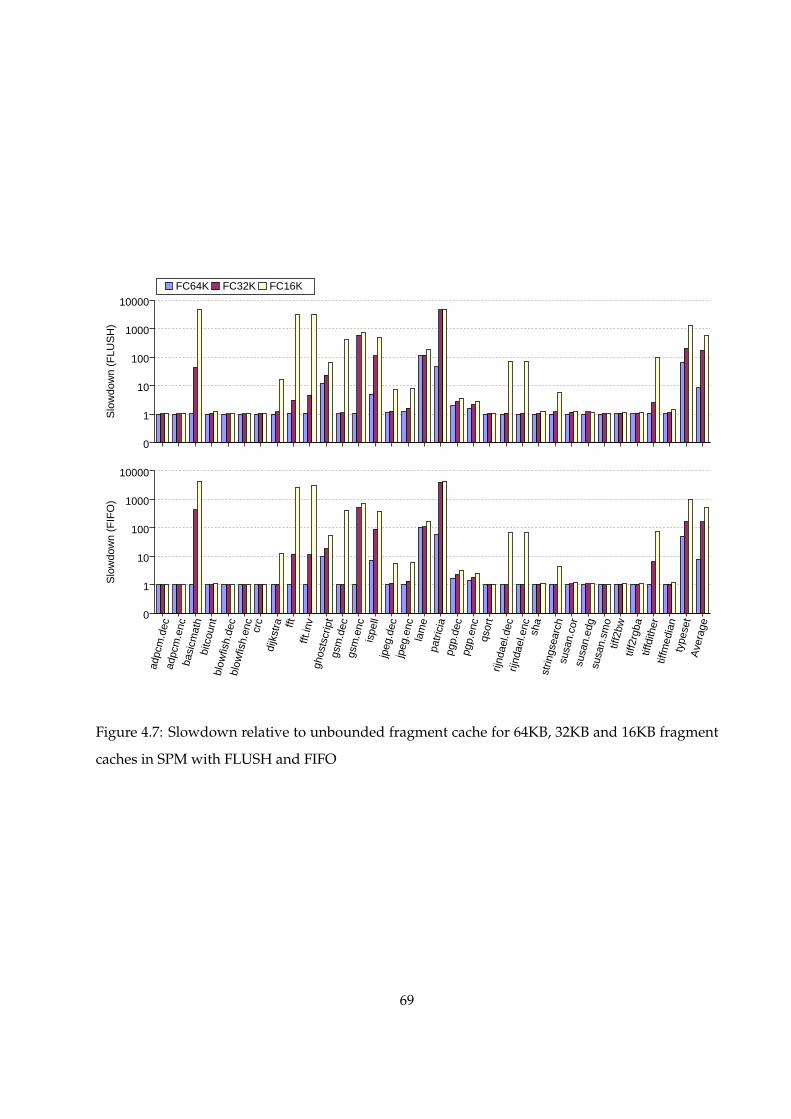
0
1
10
100
1000
10000
Slo
wdo
wn
(FLU
SH
)
FC64K FC32K FC16K
adpc
m.d
ecad
pcm
.enc
basi
cmat
hbi
tcou
ntbl
owfis
h.de
cbl
owfis
h.en
ccr
cdi
jkst
ra fftfft
.inv
ghos
tscr
ipt
gsm
.dec
gsm
.enc
ispe
lljp
eg.d
ecjp
eg.e
ncla
me
patr
icia
pgp.
dec
pgp.
enc
qsor
trij
ndae
l.dec
rijnd
ael.e
nc sha
strin
gsea
rch
susa
n.co
rsu
san.
edg
susa
n.sm
otif
f2bw
tiff2
rgba
tiffd
ither
tiffm
edia
nty
pese
tA
vera
ge
0
1
10
100
1000
10000
Slo
wdo
wn
(FIF
O)
Figure 4.7: Slowdown relative to unbounded fragment cache for 64KB, 32KB and 16KB fragment
caches in SPM with FLUSH and FIFO
69

F$, its slowdowns are 3.02x (FLUSH) and 11.88x (FIFO). However, with a 16KB F$ it has slow-
downs of 3127.97x (FLUSH) and 2605.35x (FIFO)! For patricia, significant slowdowns occur even
with a 64K F$: 46.22x (FLUSH) and 60.11x (FIFO). The situation is especially bad for 16K: 4615.15x
(FLUSH) and 4266.73x (FIFO)!
Different F$ sizes favor FIFO or FLUSH. fft does better with FLUSH for 32KB F$, but for 16KB
FIFO is the better choice. patricia prefers FLUSH for 64KB F$ and FIFO for 32KB and 16KB. As F$
pressure increases, FIFO eventually performs better than FLUSH, but the inflexion point depends
on the benchmark.
These results show that high F$ pressure leads to poor performance. Thus, the pressure must
be reduced to effectively allocate the F$ to a small SPM. Reducing the amount of control code
should help a F$ hold more fragments for a longer time before eviction. This approach is indepen-
dent of the F$ eviction policy used – it will help any eviction policy do better.
70

basi
cmat
h fftfft
.inv
ghos
tscr
ipt
gsm
.enc
ispe
lljp
eg.e
ncla
me
patr
icia
pgp.
dec
pgp.
enc
tiffd
ither
type
set
Ave
rage
0%
20%
40%
60%
80%
100%
F$
Usa
ge (
FLU
SH
)Native CallEmu Prol Indir Tramp Link
basi
cmat
h fftfft
.inv
ghos
tscr
ipt
gsm
.enc
ispe
lljp
eg.e
ncla
me
patr
icia
pgp.
dec
pgp.
enc
tiffd
ither
type
set
Ave
rage
0%
20%
40%
60%
80%
100%
F$
Usa
ge (
FIF
O)
Figure 4.8: Initial relative 32KB fragment cache usage
4.3.3 Reducing Trampoline Size
To decide which kind of control code should be tackled first, the composition of the translated code
was considered. Figure 4.8 shows the relative utilization of the F$ by each instruction category
for benchmarks that suffer at least a 50% slowdown for a 32KB F$ with FLUSH (top) and FIFO
(bottom). On average, native instructions account for less than 30% of the generated code: 28.81%
with FLUSH and 27.58% with FIFO. Trampoline instructions are the largest consumer of F$ space,
averaging 56.46% with FLUSH and 59.20% with FIFO (due to eviction preparation). Code used
to handle indirect branches averages 7.63% with FLUSH and 6.73% with FIFO. Prologue code
averages 5.40% for FLUSH and 5.22% for FIFO. Call emulation averages 1.27% for both FLUSH
and FIFO. Links average 0.42% with FLUSH and 0% with FIFO because we do not count links
when they overwrite trampolines.
For brevity, experimental results in sub-sections 4.3.3, 4.3.4 and 4.3.5 are shown for the bench-
marks in Figure 4.8 for a 32KB F$. In the final results of the section all the benchmarks are shown
for 16KB, 32KB and 64KB F$ sizes with FLUSH and FIFO.
Since trampolines are the largest source of F$ pressure, their size must be reduced first. Tram-
polines help perform a context switch from the translated program back to the translator. Tram-
poline design is guided by the target ISA and the internal design of the DBT system. The number
of instructions required by a context switch depends on the target architecture (e.g., 22 on SPARC,
71

.fcache//builder(to_PC,frag)Tr:sw $a0,a0_ofs($sp)
sw $a1,a1_ofs($sp)lui $a0,HI(to_PC)ori $a0,$a0,LO(to_PC)lui $a1,HI(&frag)ori $a1,$a1,LO(&frag)j reenter
(a) 2-Argument
.fcache//builder(link)Tr:sw $a0,a0_ofs($sp)
lui $a0,HI(&link)ori $a0,$a0,LO(&link)j reenter
.datamem//linker recordlink:to_PC
&frag
(b) 1-Argument
.fcache//builder(link)Tr:sw $ra,ra_ofs($sp)
jal reenter&link
.translatorreenter:
sw $a0_ofs($sp)lw $a0,0($ra)...
(c) Contiguous Data
.fcache//builder(Tr)Tr:sw $ra,ra_ofs($sp)
jal reenter
.datamem//trampoline maptramp:Tr
&link
(d) Mapped Data
.fcache//after $ra def.
lui $t0,HI(&shra)ori $t0,$t0,LO(&shra)sw $ra,0($t0)...
//builder(Tr)Tr:jal reenter
.translatorreenter:
...lui $t0,HI(&shra)ori $t0,$t0,LO(&shra)lw $ra,0($t0)sw $ra,ra_ofs($sp)...
(e) Shadow Link Register
Figure 4.9: Trampoline design choices
78-84 on MIPS and 10 on x86 [105]). To avoid unnecesary F$ pressure, most context save instruc-
tions in StrataX are factored into a single “re-entrance routine” (the entry point to the fragment
builder). Each trampoline needs only to perform a partial context save before jumping to the re-
entrance routine. This approach is natural for a small, bounded F$. However, there are other
unique opportunities to reduce the size of the trampoline.
4.3.3.1 Alternative Trampoline Designs The alternative designs shown in Figure 4.9 are eval-
uated. In the figure, the designs are ordered by trampoline size. A code reduction is achieved
by moving the information associated with the trampoline into data memory to free F$ space.
This increases the execution cost of executing an individual trampoline, but this additional cost is
amortized by the reduction in F$ miss rate.
Design (a), “2-argument” (2-Arg), is used in the original Strata by default. The trampoline con-
veys two pieces of information to the builder: the application address to translate and a pointer
to the fragment map entry associated with the fragment invoking the translator. Both arguments
depend on the trampoline and are set by it. In PISA, a partial context save is needed to free the
argument registers before setting the values and jumping to the re-entrance routine. The registers
72

are saved on top of the application stack (StrataX’s code does not contain accesses above the stack
pointer). With this approach, the builder can be invoked with the necessary arguments immedi-
ately after the context save, trading F$ space for a smaller dynamic instruction count.
Design (b), “1-argument” (1-Arg), exploits the fact that the fragment linker also records the
target address and source fragment of each trampoline. It passes to the builder only a pointer
to the appropriate link record (&link ). This approach inserts fewer instructions in the F$ but
performs an extra step before invoking the builder: retrieve the trampoline information from data
memory.
On many architectures, including PISA, loading a constant pointer takes more than one in-
struction. Design (c), “contiguous data” (Cont.Data), stores the link record pointer (as data) in
the instruction slot after the trampoline’s final jump, rather than using two instructions to load
the constant into a register. A jump-and-link (jal ) instruction is used to access the re-entrance
routine, so a load relative to the link register ($ra ) can be used to set the argument register for
invoking the builder. This approach saves one instruction and it’s relatively fast when the F$ is in
SPM.
Even more F$ space can be saved by storing the trampoline data in main memory rather than
in the F$. For this purpose, a hash table indexed by trampoline address is used to store and recover
the trampoline data. Design (d), “mapped data” (Map.Data), implements this approach. It trades
data memory (an extra hash table) for fewer instructions in the F$. It also increases the execution
cost of the trampoline since a hash table lookup must be performed by the re-entrance routine.
Design (e), “shadow link register” (ShadowLR), saves even more space by avoiding the spill
of the link register in every trampoline before its value is overwritten (by the jump-and-link). This
approach requires the translator to identify which instructions change the value of $ra and insert
code to update the value of a shadow variable (shra ). Trampolines can then safely overwrite $ra
since the re-entrance routine uses the value in shra to perform the context save. The tradeoff is
that if the application code changes the value of $ra too often, the translated code size could be
increased. Fortunately, $ra is typically defined only by non-leaf procedures when passing the
return address to callees and when recovering their own return address from the stack. Because
the number of calls and returns from non-leaf procedures is usually much smaller than the number
of direct CTIs in the program that require a trampoline, this technique can be very effective.
For further space savings when implementing design (e), the shadow variable update code
is added to the beginning of callee fragments rather at the call sites. When translated, a direct
73

0
1
10
100
1000
10000
Slo
wdo
wn
(FLU
SH
)
2-Args 1-Arg Cont-Data Map-Data ShadowLR
basi
cmat
h fft
fft.in
v
ghos
tscr
ipt
gsm
.enc
ispe
ll
jpeg
.enc
lam
e
patr
icia
pgp.
dec
pgp.
enc
tiffd
ither
type
set
Ave
rage
0
1
10
100
1000
10000
Slo
wdo
wn
(FIF
O)
Figure 4.10: Performance of trampoline designs for a 32KB fragment cache
call is transformed into a jump and call emulation instructions are inserted to set the value of
the link register to the application return address. If the callee is not found in the F$, the reentry
code accessed by the trampoline obtains the correct value of the link register by decoding the call
emulation instructions and updates the shadow variable. When the target fragment of the call
is translated, the code to update the shadow variable is added at the beginning. This strategy
preserves correctness after fragment linking.
A DBT system may perform register rellocation [74, 83], so design (e) could be realized by
reserving the link register for exclusive use by the translator. Ensuring that the translated code
does not redefine the link register makes the shadow variable unnecessary. However, reducing
the number of registers available to the transalted code may increase translated code size due to
additional spill code. StrataX does not perform register rellocation, so this possibility is not further
explored.
4.3.3.2 Evaluation Figure 4.10 shows the performance of the benchmarks for a 32KB F$ rela-
tive to an unbounded F$. For some benchmarks, the initial gain obtained with “1-Argument”
74

basi
cmat
h fftfft
.inv
ghos
tscr
ipt
gsm
.enc
ispe
lljp
eg.e
ncla
me
patr
icia
pgp.
dec
pgp.
enc
tiffd
ither
type
set
Ave
rage
0%
20%
40%
60%
80%
100%
F$
Usa
ge (
FLU
SH
)Native CallEmu Prol Indir Tramp Link LRSync
basi
cmat
h fftfft
.inv
ghos
tscr
ipt
gsm
.enc
ispe
lljp
eg.e
ncla
me
patr
icia
pgp.
dec
pgp.
enc
tiffd
ither
type
set
Ave
rage
0%
20%
40%
60%
80%
100%
F$
Usa
ge (
FIF
O)
Figure 4.11: Relative 32KB fragment cache usage after Shadow LR
is significant: basicmath goes from 43.44x slowdown with FLUSH and 427.83x slowdown with
FIFO to just 1.25x and 1.33x! Once close to the ideal, the improvements are less impressive: fft
goes from initial slowdowns of 3.02x and 11.88x with FLUSH and FIFO to overheads of 4% and
2% for “1-Argument”. Other designs do not achieve further improvement. In benchmarks with
high F$ pressure, the effect is progressive: ghostscript has slowdowns of 23.24x (2-Arg), 15.07x
(1-Arg), 14.18x (Cont.Data), 13.41x (Map.Data) and 12.85x (ShadowLR) with FLUSH. patricia has
slowdowns of 65.69x with FLUSH and 51.1x with FIFO when using ShadowLR. However, the
other designs have slowdowns beyond 1000x. The greatest improvement overall is achieved with
ShadowLR, so it is StrataX’s chosen trampoline design.
4.3.4 Reducing Indirect CTI Handling Code Size
Figure 4.11 shows the new 32KB F$ utilization after “2-Argument” trampolines are replaced with
the “Shadow Link Register” design. With both FLUSH and FIFO, native instructions now account
for 59.2% of the F$ on average, while trampoline instructions are reduced to an average of 12.38%
(FLUSH) and 13.65% (FIFO). A new instruction category (“LR Sync”) is introduced to account for
the code needed to update the shadow variable; it averages 2.99% with FLUSH and 2.95% with
FIFO. These results indicate that when F$ pressure is high, even a small reduction in trampoline
size has a dramatic effect on performance due to improved F$ usage.
75
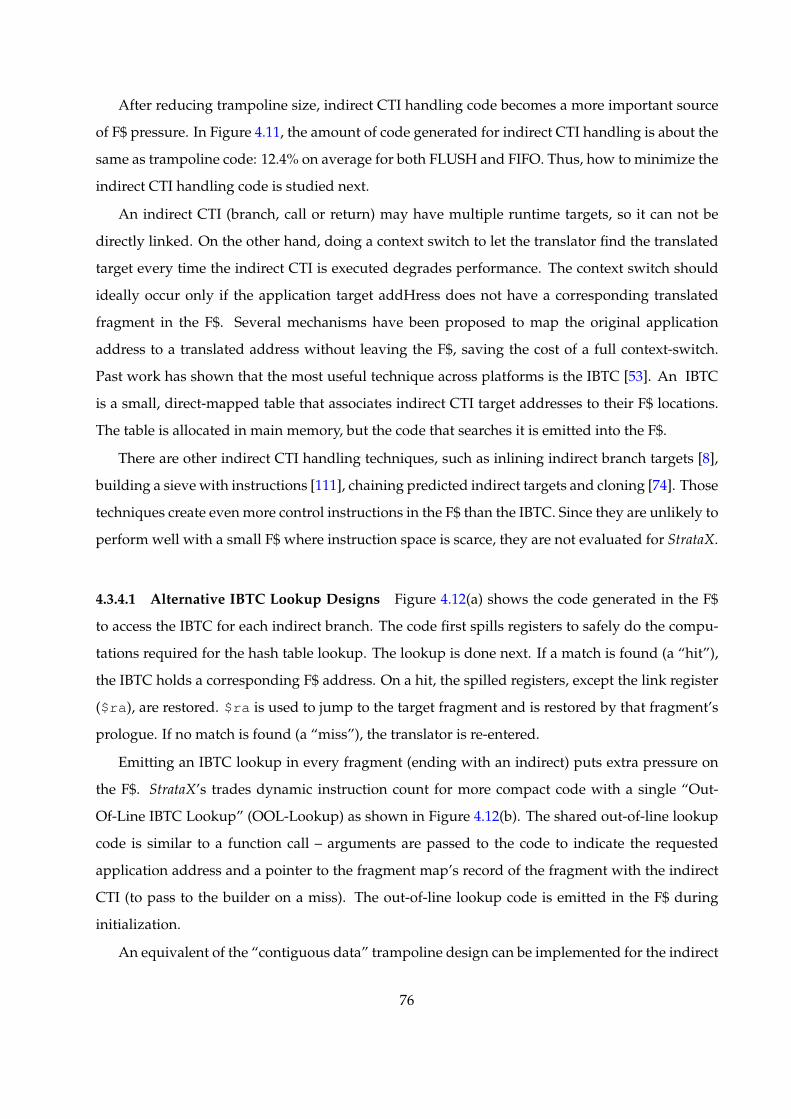
After reducing trampoline size, indirect CTI handling code becomes a more important source
of F$ pressure. In Figure 4.11, the amount of code generated for indirect CTI handling is about the
same as trampoline code: 12.4% on average for both FLUSH and FIFO. Thus, how to minimize the
indirect CTI handling code is studied next.
An indirect CTI (branch, call or return) may have multiple runtime targets, so it can not be
directly linked. On the other hand, doing a context switch to let the translator find the translated
target every time the indirect CTI is executed degrades performance. The context switch should
ideally occur only if the application target addHress does not have a corresponding translated
fragment in the F$. Several mechanisms have been proposed to map the original application
address to a translated address without leaving the F$, saving the cost of a full context-switch.
Past work has shown that the most useful technique across platforms is the IBTC [53]. An IBTC
is a small, direct-mapped table that associates indirect CTI target addresses to their F$ locations.
The table is allocated in main memory, but the code that searches it is emitted into the F$.
There are other indirect CTI handling techniques, such as inlining indirect branch targets [8],
building a sieve with instructions [111], chaining predicted indirect targets and cloning [74]. Those
techniques create even more control instructions in the F$ than the IBTC. Since they are unlikely to
perform well with a small F$ where instruction space is scarce, they are not evaluated for StrataX.
4.3.4.1 Alternative IBTC Lookup Designs Figure 4.12(a) shows the code generated in the F$
to access the IBTC for each indirect branch. The code first spills registers to safely do the compu-
tations required for the hash table lookup. The lookup is done next. If a match is found (a “hit”),
the IBTC holds a corresponding F$ address. On a hit, the spilled registers, except the link register
($ra ), are restored. $ra is used to jump to the target fragment and is restored by that fragment’s
prologue. If no match is found (a “miss”), the translator is re-entered.
Emitting an IBTC lookup in every fragment (ending with an indirect) puts extra pressure on
the F$. StrataX’s trades dynamic instruction count for more compact code with a single “Out-
Of-Line IBTC Lookup” (OOL-Lookup) as shown in Figure 4.12(b). The shared out-of-line lookup
code is similar to a function call – arguments are passed to the code to indicate the requested
application address and a pointer to the fragment map’s record of the fragment with the indirect
CTI (to pass to the builder on a miss). The out-of-line lookup code is emitted in the F$ during
initialization.
An equivalent of the “contiguous data” trampoline design can be implemented for the indirect
76

.fcache//for each indirect
sw $a0,a0_ofs($sp)sw $a1,a1_ofs($sp)sw $ra,ra_ofs($sp)add $a0,$z0,$rt
lkup: //$ra = &table//$a1 = hash($a0)//$ra = $ra[$a1]lw $a1,PC_ofs($ra)bne $a1,$a0,miss
hit: lw $ra,FPC_ofs($ra)lw $a0,a0_ofs($sp)lw $a1,a1_ofs($sp)jr $ra
miss: lui $a1,HI(&frag)ori $a1,$a1,LO(&frag)j reenter_ibtc
(a) Inline IBTC Lookup
.fcache//for each indirect
sw $a0,a0_ofs($sp)sw $a1,a1_ofs($sp)add $a0,$z0,$rtlui $a1,HI(&frag)ori $a1,$a1,LO(&frag)j lkup
//shared by all indirectslkup: sw $ra,ra_ofs($sp)
sw $a1,at_ofs($sp)//$ra = &table//$a1 = hash($a0)...
miss: lw $a1,at_ofs($sp)j reenter_ibtc
(b) Out-of-line IBTC Lookup (OOL-Lkup)
.fcache//for each indirect
sw $ra,ra_ofs($sp)sw $a0,a0_ofs($sp)add $a0,$z0,$rtjal lkup&frag
//shared by all indirectslkup: sw $a1,a1_ofs($sp)
lw $a1,0($ra)sw $a1,at_ofs($sp)//$ra = &table//$a1 = hash($a0)...
miss: lw $a1,at_ofs($sp)j reenter_ibtc
(c) Contiguous Data Indirect (CDI)
.fcache//for each indirect
sw $ra,ra_ofs($sp)jal l$rt&frag
//shared by $rt-indirectsl$rt: sw $a0,a0_ofs($sp)
add $a0,$z0,$rtj lkup
//shared by returnsl$ra: sw $a0,a0_ofs($sp)
lw $a0,ra_ofs($sp)//shared by all indirectslkup: sw $a1,a1_ofs($sp)
lw $a1,0($ra)...
(d) Shared Target Register Copies (STRC)
Figure 4.12: Indirect CTI handling with an IBTC
77

CTI handling code, as shown in Figure 4.12(c). The “contiguous data indirect” uses a jump-and-
link (jal ) instruction to invoke the out-of-line IBTC lookup. The address of the requesting frag-
ment’s record is saved in the instruction slot following the jal . In the lookup code, a load relative
to the link register ($ra ) is used to load the fragment’s record address into the appropriate register
if needed (i.e., on an IBTC miss).
The out-of-line IBTC lookup code uses a fixed argument register ($a0 ) for the target applica-
tion address. To do a lookup, the register ($rt ) that contains the address must be copied to the
argument register. For further gain, our approach, called “Shared Target Register Copies” (STRC),
shares the code that performs this copy among all indirect CTIs that use the same target register.
As shown in Figure 4.12(d), the code generated for each indirect CTI spills $ra and uses a jal to
go to an entry point in the out-of-line shared code that depends on the target register ($rt ) used.
For each unique $rt , a single transfer routine spills the argument register ($a0 ), copies $rt to
$a0 and jumps to the IBTC lookup code. The transfer routines are emitted on-demand as new
target registers are discovered at run-time.
A final alternative is to implement “Shared Target Register Copies” as part of StrataX’s code
in ROM (STRC-ROM) rather than emitting the code into the F$. In this way, it is possible to
have shared transfer routines for all p32KB ossible registers with no generation cost and no use
of fragment cache space. This is better than on-demand generation, which may need to revert to
the “Contiguous Data” design if there’s no room in the F$ (i.e., when FIFO is used). On the other
hand, the IBTC address (a pointer to the table) can not be emitted as a constant in the code, but
must be obtained from a variable.
4.3.4.2 Evaluation Figure 4.13 shows the performance of the benchmarks with the proposed
IBTC lookup designs. The Inline IBTC Lookup approach is the one used by Original Strata. Shad-
owLR is used for trampolines in all of these experiments. Progressive improvements are obtained
with each scheme.
The greatest improvement is obtained for patricia: its 65.69x slowdown with FLUSH after Shad-
owLR is reduced to 1.83x by moving the IBTC lookup code out-of-line, making its code fit in the
small SPM. Further reductions are obtained with contiguous data and sharing the target register
copy code: 1.37x (CDI), 1.22x (STRC) and 1.23x (STRC-ROM). ghostscript shows more steady slow-
down reductions. For instance, ghostscript slowdowns with FLUSH are 12.85x (ShadowLR), 11.80x
(OOL-Lkup), 11.61x (CDI), 11.22x (STRC) and 10.92x (STRC-ROM).
78

0
1
10
100
1000
Slo
wdo
wn
(FLU
SH
)
ShadowLR OOL-Lkup CDI STRC STRC-ROM
basi
cmat
h fft
fft.in
v
ghos
tscr
ipt
gsm
.enc
ispe
ll
jpeg
.enc
lam
e
patr
icia
pgp.
dec
pgp.
enc
tiffd
ither
type
set
Ave
rage
0
1
10
100
1000
Slo
wdo
wn
(FIF
O)
Figure 4.13: Performance of IBTC lookup placements for 32KB fragment cache
Benchmarks that already fit in the SPM, however, suffer some performance degradation due
to an increase in the number of jumps. The 5% overhead of basicmath with FIFO and ShadowLR is
increased to 7% (OOL-Lkup and CDI), 8% (STRC) and 11% (STRC-ROM). Similar overheads are
obtained for basicmath with FLUSH.
StrataX uses “Shared Target Register Copies” implemented as part of its static code (STRC-
ROM) to handle indirect CTIs because it has the best performance among the evaluated alterna-
tives.
4.3.5 Eliminating the Fragment Prologue
Figure 4.14 shows the 32KB F$ utilization after STRC-ROM replaces the original inline IBTC
lookup. Native instructions now account for 68.87% with FLUSH and for 68.78% with FIFO (an
increase of about 10% after enabling only ShadowLR). Indirect CTI handling code is reduced to
an average of 2.29% with FLUSH and 2.26% with FIFO.
After reducing the indirect branch handling code, fragment prologue instructions now account
for an average 9% of the F$. Thus, they are the remaining category of control code reduced in
79

basi
cmat
h fftfft
.inv
ghos
tscr
ipt
gsm
.enc
ispe
lljp
eg.e
ncla
me
patr
icia
pgp.
dec
pgp.
enc
tiffd
ither
type
set
Ave
rage
0%
20%
40%
60%
80%
100%
F$
Usa
ge (
FLU
SH
)Native CallEmu Prol Indir Tramp Link LRSync
basi
cmat
h fftfft
.inv
ghos
tscr
ipt
gsm
.enc
ispe
lljp
eg.e
ncla
me
patr
icia
pgp.
dec
pgp.
enc
tiffd
ither
type
set
Ave
rage
0%
20%
40%
60%
80%
100%
F$
Usa
ge (
FIF
O)
Figure 4.14: Relative 32KB F$ usage after STRC IBTC lookup
StrataX.
4.3.5.1 Self-Modifying Control Transfer The original exec routine in Strata/MIPS, shown in
Figure 4.15(a), uses an indirect jump to transfer control to the fragment whose address is stored in
the link register ($ra ). Thus, the fragment prologue must restore $ra . On an IBTC hit, restoring
$ra is also done by the fragment prologue. StrataX uses self-modifying code to eliminate the need
for prologue code.
Rather than transferring control to a fragment through an indirect jump, StrataX rewrites the
target of a direct jump to go to the fragment. This approach, which we call “Self-Modifying Con-
trol Transfer” (SMCT), is illustrated in Figure 4.15(b). As shown, instead of ending with an indirect
jump, the routine that returns control to the F$ (sm exec ) rewrites its last instruction to be a direct
jump to the target fragment. In systems with instruction and data caches, self-modifying code re-
quires synchronization between the caches. Depending on architectural details, this operation can
be expensive since it may require flushing a cache line or the entire instruction cache. However,
in many embedded designs, SPM addresses are not cached and a data write immediately modi-
fies the SPM. As a result, synchronization is not needed and self-modifying code is inexpensive.
Because StrataX is in ROM, our implementation initially emits the “return routine” into the F$ on
start-up. The code for an IBTC hit must also be modified: to go to the target fragment, a direct
80

.translatorexec: //$a0==Fx
add $ra,$z0,$a0ctxt_restore:
addiu $sp,$sp,+SIZE...lw $a1,a1_ofs($sp)lw $a0,a0_ofs($sp)j $ra
.fcacheFx://target fragment
lw $ra,ra_ofs($sp)xxx $rx,$ry,$rz...
(a) Original
.fcachesm_exec: //$a0==Fx
//$a0 = [j Fx]lui $ra,HI(Jx)ori $ra,LO(Jx)sw $a0,0($ra)jal ctxt_restorelw $ra,ra_ofs($sp)
Jx:j ????
Fx://target fragmentxxx $rx,$ry,$rz...
(b) Self-Modifying
.translatorsm_exec: //$a0==Fx
//$a0 = [j Fx]//$ra = *ptr_Jxsw $a0,4($ra)jal ctxt_restorejr $ra
.fcacheJx:lw $ra,ra_ofs($sp)
j ????
Fx://target fragmentxxx $rx,$ry,$rz...
(c) Self-Modifying in ROM
Figure 4.15: Control transfer to fragment
jump is overwritten with the target fragment address found in the IBTC.
Another alternative is shown in Figure 4.15(c), SMCT-ROM. In this case, the code that over-
writes the jump is part of Strata (stored in ROM) so only two instructions are used in the F$ to
restore the link register and jump to the fragment through the modified jump. The cost is an extra
indirection: the address of the smaller “return routine” in the F$ is stored in a variable, from which
it is loaded to the link register ($ra ).
Without SMCT, it is impossible to maintain correctness if control needs to be transferred from
the translator to an instruction that does not follow a fragment prologue, since the target regis-
ter would not be restored. SMCT allows StrataX to create PC mappings for locations in which
a fragment is not stopped after a direct CTI is processed, needed by some fragment formation
strategies.
4.3.5.2 Bottom Jump Eliding After eliminating the prologue, there is no need to skip it when
fragments are linked. If a trampoline is the last piece of code emitted into the F$, instead of patch-
ing it with a jump to the new fragment, the trampoline can be overwritten with the fragment code.
“Bottom Jump Eliding” (BJE) implements this idea. Figure 4.16 shows the translation of direct calls
and branches before (middle) and after (bottom) modifying the fragment to let it fall-through into
its successor fragment. For unconditional jumps, calls and taken conditional branches, as shown
in Figure 4.16(a)-(b), it is enough to start the new fragment in place of the trampoline. For not
81

.binaryjal Foo
RPC: ... //return address
.fcache//Before Foo translated
lui $ra,HI(RPC)ori $ra,$ra,LO(RPC)jal reenter //Tr(Foo)
.fcache//After Foo translated
lui $ra,HI(RPC)ori $ra,$ra,LO(RPC)
F$Foo: //new fragment
(a) Call
.binarybeq $rx,$ry,TPC
NPC: ... //fallthrough
.fcache//Before TPC translated
beq $rx,$ry,TTrjal reenter //Tr(NPC)
TTr: jal reenter //Tr(TPC)
.fcache//After TPC translated
beq $rx,$ry,F$TPCjal reenter //Tr(NPC)
F$TPC: //new fragment
(b) Conditional Taken
.binarybeq $rx,$ry,TPC
NPC: ... //fallthrough
.fcache//Before NPC translated
beq $rx,$ry,TTrjal reenter //Tr(NPC)
TTr: jal reenter //Tr(TPC)
.fcache//After NPC translated
bne $rx,$ry,F$NPCjal reenter //Tr(TPC)
F$NPC: //new fragment
(c) Conditional Not Taken
Figure 4.16: Bottom Jump Eliding (BJE)
taken conditional branches, the branch condition must be negated to maintain correctness, and
the trampoline for the original not-taken target modified to request the translation of the original
taken target instead.
When combining BJE with F$ management policies (e.g., LRU) that may evict the successor
fragment but not the fragment that flows into it, the trampoline must be regenerated. To enable
BJE, a DBT system must guarantee that the evicted fragment is bigger than a jump when using the
trampoline pool or bigger than a trampoline when interleaving fragments and trampolines. With
single-instruction trampolines, all fragments satisfy this condition.
On some architectures, like ARM [80], it is possible to transfer control from the translator to a
fragment without adding prologue code. In those cases, prologue elimination is unnecessary but
Bottom Jump Eliding is still applicable.
4.3.5.3 Evaluation Figure 4.17 shows the slowdown of the benchmarks without (STRC-ROM)
and with prologue elimination (SMCT and SMCT-ROM). The results after enabling Bottom Jump
Eliding with SMCT-ROM are also shown (BJE). High-pressure benchmarks show significant im-
provements: ghostscript with FLUSH goes from a 10.92x slowdown (STRC-ROM) to 8.9x (SMCT
and SMCT-ROM) and 6.65x with BJE. With FIFO, ghostscript slowdown is reduced from 8.24x
(STRC-ROM) to 6.41x (SMCT and SMCT-ROM) and 4.67x (BJE).
In some benchmarks, SMCT increases the slowdown and BJE helps reduce it again. This situa-
82

0
1
10
100
1000
Slo
wdo
wn
(FLU
SH
)
STRC-ROM SMCT SMCT-ROM BJE
basi
cmat
h fft
fft.in
v
ghos
tscr
ipt
gsm
.enc
ispe
ll
jpeg
.enc
lam
e
patr
icia
pgp.
dec
pgp.
enc
tiffd
ither
type
set
Ave
rage
0
1
10
100
1000
Slo
wdo
wn
(FIF
O)
Figure 4.17: Performance with SMCS, SMCS-ROM and BJE for 32KB fragment cache
tion happens for pgp-sign with FLUSH. It has a 1.57x slowdown with STRC-ROM, which increases
to 1.61x with SMCT and SMCT-ROM. With BJE, the slowdown is decreased to 1.49x. Performance
differences between SMCT and SMCT-ROM are only noticeable for the benchmarks with very
high slowdowns, e.g., typeset has slowdowns of 50.82x and 50.26x (FLUSH).
Figure 4.18 shows the F$ usage after BJE. In this case, the replaced links are discounted and
the prologue has been eliminated, leaving more room for native instructions. They now aver-
age 83% (FLUSH) and 81.7% (FIFO). StrataX uses the “self-modifying control transfer” (in ROM)
combined with “bottom jump eliding”, since this combination achieves the better performance
improvement.
83
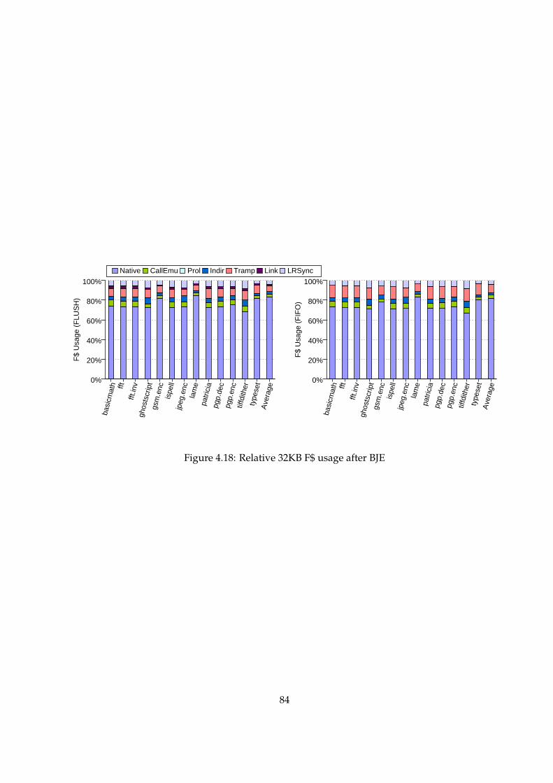
basi
cmat
h fftfft
.inv
ghos
tscr
ipt
gsm
.enc
ispe
lljp
eg.e
ncla
me
patr
icia
pgp.
dec
pgp.
enc
tiffd
ither
type
set
Ave
rage
0%
20%
40%
60%
80%
100%
F$
Usa
ge (
FLU
SH
)
Native CallEmu Prol Indir Tramp Link LRSync
basi
cmat
h fftfft
.inv
ghos
tscr
ipt
gsm
.enc
ispe
lljp
eg.e
ncla
me
patr
icia
pgp.
dec
pgp.
enc
tiffd
ither
type
set
Ave
rage
0%
20%
40%
60%
80%
100%
F$
Usa
ge (
FIF
O)
Figure 4.18: Relative 32KB F$ usage after BJE
84

4.3.6 Translated Code Composition with Footprint Reduction
Figure 4.19 shows the amount of code generated per benchmark for each instruction category
when the F$ is unbounded. A significant reduction is obtained relative to the initial composition
in Figure 4.6. For most benchmarks, the amount of translated code now does not exceed 32KB,
and some even fit in 16KB. For example, the native and call emulation code for basicmath sum to
25KB. Initially, the control code for basicmath was 53KB, adding to a total code size of 78KB that
overflows even the 64KB SPM. After applying our techniques, the control code for basicmath is less
than 7KB. Thus, the total translated code for basicmath now fits in a 32KB SPM.
For some benchmarks, the sum of native and call emulation code exceeds the capacity of the
bounded F$ (e.g., ghostscript and typeset). However, a significant reduction is still obtained in the
amount of control code generated. For example, the final control code for typeset is 45.7KB, but
initially it was 443.5KB. This helps to improve performance. However, the 240KB of native and
call emulation code for typeset still exceeds the evaluated SPM sizes.
4.3.7 Performance With Footprint Reduction
Figure 4.20 shows the slowdowns of all benchmarks relative to the initial unbounded F$. StrataX’s
techniques achieve significant improvements when the translated code working set did not fit ini-
tially in the F$ due to excessive DBT control code. For example, basicmath initially had a 4702.09x
slowdown for a 16KB F$ and 43.44x for a 32KB F$ with FLUSH. The best StrataX techniques reduce
these slowdowns to only 1.51x (16KB) and 1.13x (32KB). The final slowdown for a 64KB F$ is 1.12x.
It was initially only 1.01x, which indicates a performance cost associated with our techniques that
is not amortized when the translated code working set fits in the F$.
patricia has an impressive improvement. For a 32KB F$, its initial slowdowns were 4605.60x
with FLUSH and 4018.44x with FIFO. Our techniques reduce both of them to 1.08x. dijkstra in
a 16KB F$ is another example. Our techniques make its final performance equivalent to the un-
bounded F$ after an initial 17.02x slowdown.
Although our techniques reduce slowdown by improving the usage of the small F$ in SPM,
there are situations where the slowdowns can not be overcome. For instance, in a 32KB F$ with
FLUSH, the initial slowdown of 117.70x for lame is barely reduced to 116.22x. Our techniques
help somewhat, but can not fully overcome the performance degradation when the application
code working set does not fit in the F$.
85

adpc
m.d
ecad
pcm
.enc
basi
cmat
hbi
tcou
ntbl
owfis
h.de
cbl
owfis
h.en
ccr
cdi
jkst
ra fftfft
.inv
ghos
tscr
ipt
gsm
.dec
gsm
.enc
ispe
lljp
eg.d
ecjp
eg.e
ncla
me
patr
icia
pgp.
dec
pgp.
enc
qsor
trij
ndae
l.dec
rijnd
ael.e
nc sha
strin
gsea
rch
susa
n.co
rsu
san.
edg
susa
n.sm
otif
f2bw
tiff2
rgba
tiffd
ither
tiffm
edia
nty
pese
t 0
16
32
48
64
80
96
112
128
144
160
176
192
208
224
240
256
272
288
Kilo
byte
s (U
nbou
nded
)
Native CallEmu Prol Indir Tramp Link LRSync
Figure 4.19: Final translated code size with footprint reduction for an unbounded fragment cache
86

0.00
0.25
0.50
0.75
1.00
1.25
1.50
1.75
2.00
Slo
wdo
wn
(FLU
SH
)
FC64K FC32K FC16K
adpc
m.d
ecad
pcm
.enc
basi
cmat
hbi
tcou
ntbl
owfis
h.de
cbl
owfis
h.en
ccr
cdi
jkst
ra fftfft
.inv
ghos
tscr
ipt
gsm
.dec
gsm
.enc
ispe
lljp
eg.d
ecjp
eg.e
ncla
me
patr
icia
pgp.
dec
pgp.
enc
qsor
trij
ndae
l.dec
rijnd
ael.e
nc sha
strin
gsea
rch
susa
n.co
rsu
san.
edg
susa
n.sm
otif
f2bw
tiff2
rgba
tiffd
ither
tiffm
edia
nty
pese
tA
vera
ge
0.00
0.25
0.50
0.75
1.00
1.25
1.50
1.75
2.00
Slo
wdo
wn
(FIF
O)
157.95.6157.228.94.12.54231.3119.5116.273.8580.614.56.6
147.74.9116.718.03.14034.4109.3106.150.4520.912.34.7
Figure 4.20: Final slowdown with control code footprint reduction relative to initial unbounded
fragment cache
87

0 1 2 3 4 5 6 7 8 910
Spe
edup
(F
LUS
H)
FC64K FC32K FC16K
adpc
m.d
ecad
pcm
.enc
basi
cmat
hbi
tcou
ntbl
owfis
h.de
cbl
owfis
h.en
ccr
cdi
jkst
ra fftfft
.inv
ghos
tscr
ipt
gsm
.dec
gsm
.enc
ispe
lljp
eg.d
ecjp
eg.e
ncla
me
patr
icia
pgp.
dec
pgp.
enc
qsor
trij
ndae
l.dec
rijnd
ael.e
nc sha
strin
gsea
rch
susa
n.co
rsu
san.
edg
susa
n.sm
otif
f2bw
tiff2
rgba
tiffd
ither
tiffm
edia
nty
pese
tA
vera
ge
0 1 2 3 4 5 6 7 8 910
Spe
edup
(F
IFO
)
284.8150.915.687.864.363.84259.242.968.996.2540.8424.72874.22701.515.03110.038.5
264.4144.016.375.963.166.23721.355.672.181.6505.3418.32731.210.12306.110.612.22996.4379.6
Figure 4.21: Speedup with control code footprint reduction
StrataX control code footprint reduction techniques reduce code size and lead to a performance
improvement regardless of the F$ management technique. Figure 4.21 shows the performance
improvement after the application of these techniques for the 64KB, 32KB and 16KB F$. When
applying the techniques with FLUSH, speedups are 5.13x for a 64KB F$, 150.94x for a 32KB F$
and 284.83x for a 16KB F$ relative to the initial performance. The speedups with FIFO are 5.65x
(64KB), 144.05x (32KB) and 264.40x (16KB).
88

5.0 FRAGMENT CACHE MANAGEMENT
This chapter studies several F$ management techniques that make it effective to exploit the fast but
small SPM to hold the F$ in a DBT system. The chapter is organized as follows. Section 5.1 com-
pares a F$ layout that places trampolines in their own section of the F$ with the single-instruction
trampolines used in StrataX. It shows that the two have similar performance, but the approach in
StrataX is much simpler. Section 5.2 shows how to create a F$ that spans across SPM and main
memory when both a SPM and a hardware instruction cache are available. It shows how this het-
erogeneous F$ can be managed effectively to order to reduce off-chip memory accesses. Section 5.3
shows how to amortize the high re-translation cost when code is incrementally loaded from Flash
into the SPM and there is no hardware instruction cache. Victim fragments are saved in a com-
pressed code region in the SPM rather than deleted, and “pinned” to the F$ upon decompression
to reduce the number of premature evictions. Finally, Section 5.4 shows how StrataX can provide
a form of demand paging for code stored in NAND Flash, and how to manage unstranlated and
translated code pages in a unified manner to save memory.
5.1 FRAGMENT CACHE LAYOUT
This section compares two alternative F$ layouts, one with interleaved fragments and trampo-
lines, and another where fragments and trampolines are stored in separate regions of the F$. The
arrangement of fragments and trampolines inside the F$ plays a role in F$ pressure, so the purpose
of this section is to evaluate how well StrataX’s single-instruction trampolines, which naturally
lead to an interleaved layout, perform relative to the alternative.
89

High address
Low addressF1
T1
F2
T2
F3
T3 next
Free Space
(a) Interleaved
High address
Low addressF1
F2
F3 next_frag
Free Space
T1
T3free_tramp
next_tramp
(b) Trampoline Pool
Figure 5.1: Trampoline placement alternatives
5.1.1 Fragment Cache Layout Alternatives
Figure 5.1(a) illustrates the interleaved F$ layout, in which fragments are trampolines are created in
the F$ [8] as they are needed and placed in the next available address. A disadvantage of this lay-
out becomes aparent after fragment linking. Tipically, a trampoline uses many more instructions
than a link to its target fragment, so a “hole” appears in the F$ after the trampoline is patched.
Trampoline code is dead but its space, precious for a small F$, can not be reused because it is too
small to hold a new fragment.
A key observation is that a trampoline is executed at most once. It might even never be ex-
ecuted if its target fragment is requested by another trampoline, or its associated fragment gets
deleted. To address this issues, an alternative arrangement, shown in Figure 5.1(b) uses a trampo-
line pool. With a trampoline pool, a trampoline can be deleted or reused by a different fragment
after its original fragment has been linked [43]. StrataX can be configured so a trampoline pool
is placed at one end of the F$, while the translated code is placed at the oppossite end. In this
arrangement, the currently translated fragment and the trampoline pool grow towards each other.
A third option, also supported by StrataX but not evaluated, is to place fragments and trampo-
lines in different segments in the F$ [52]. The reason for not evaluating this alternative is that it is
less flexible and requires estimating in advance the relative space requirements of fragments and
trampolines.
90

if free tramp 6= nil then {free trampoline available}tramp addr ← free trampfree tramp← ∗tramp addr {pop from free list}
else {create a new trampoline}next tramp← next tramp− tramp size {the pool grows}tramp addr ← next tramp
end ifemit trampoline at tramp addr
Algorithm 5.1: Emit New Trampoline in Pool
5.1.2 Trampoline Pool Management
How the trampoline pool is managed also affects DBT overhead and F$ pressure. For example, a
management scheme could trade space utilization for less translation time. The following strate-
gies are evaluated:
(a) Delete the trampoline at the top of the pool when its associated fragment is linked [43]. The
space occupied by the deleted trampoline can be reused for a new trampoline or fragment. The
advantage to this technique is its simplicity and ability for the pool to shrink. Its disadvantage,
however, is that any free space inside the pool can not be reclaimed.
(b) Maintain a trampoline Free List. This approach needs a list head pointer; a free trampoline itself
embeds a pointer to the next free trampoline in the list. When a trampoline is needed and the
free list is not empty, the last trampoline added to the list is reused. The pool is grown when
all current trampolines are active, i.e., when the list is empty. No attempt is made to compact
(shrink) the pool when it has free entries. The advantage to this scheme is its flexibility to reuse
trampolines inside the pool. Its disadvantage is the cost of maintaining the free list.
(c) Combined deletion and free list. In this scheme, the trampoline at the top of the pool is deleted
when its fragment is linked. Otherwise, the free trampoline is added to the free list for future
reuse. This scheme attempts to gain the advantages of both (a) and (b). With the combined
scheme, Algorithm 5.1 is used for allocating a trampoline, while Algorithm 5.2 is used for
reclaiming a trampoline in the pool after linking its fragment.
The trampoline pool makes it difficult to implement fine-grained F$ management policies such
as FIFO. In previous studies [43, 52], the trampoline pool is discarded along its associated frag-
91
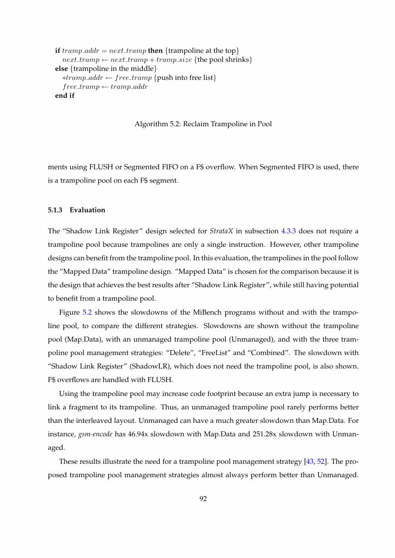
if tramp addr = next tramp then {trampoline at the top}next tramp← next tramp + tramp size {the pool shrinks}
else {trampoline in the middle}∗tramp addr ← free tramp {push into free list}free tramp← tramp addr
end if
Algorithm 5.2: Reclaim Trampoline in Pool
ments using FLUSH or Segmented FIFO on a F$ overflow. When Segmented FIFO is used, there
is a trampoline pool on each F$ segment.
5.1.3 Evaluation
The “Shadow Link Register” design selected for StrataX in subsection 4.3.3 does not require a
trampoline pool because trampolines are only a single instruction. However, other trampoline
designs can benefit from the trampoline pool. In this evaluation, the trampolines in the pool follow
the “Mapped Data” trampoline design. “Mapped Data” is chosen for the comparison because it is
the design that achieves the best results after “Shadow Link Register”, while still having potential
to benefit from a trampoline pool.
Figure 5.2 shows the slowdowns of the MiBench programs without and with the trampo-
line pool, to compare the different strategies. Slowdowns are shown without the trampoline
pool (Map.Data), with an unmanaged trampoline pool (Unmanaged), and with the three tram-
poline pool management strategies: “Delete”, “FreeList” and “Combined”. The slowdown with
“Shadow Link Register” (ShadowLR), which does not need the trampoline pool, is also shown.
F$ overflows are handled with FLUSH.
Using the trampoline pool may increase code footprint because an extra jump is necessary to
link a fragment to its trampoline. Thus, an unmanaged trampoline pool rarely performs better
than the interleaved layout. Unmanaged can have a much greater slowdown than Map.Data. For
instance, gsm-encode has 46.94x slowdown with Map.Data and 251.28x slowdown with Unman-
aged.
These results illustrate the need for a trampoline pool management strategy [43, 52]. The pro-
posed trampoline pool management strategies almost always perform better than Unmanaged.
92

basi
cmat
h fft
fft.in
v
ghos
tscr
ipt
gsm
.enc
ispe
ll
jpeg
.enc
lam
e
patr
icia
pgp.
dec
pgp.
enc
tiffd
ither
type
set
Ave
rage
0
1
10
100
1000
10000
Slo
wdo
wn
(FLU
SH
)Map-Data Unmanaged Delete FreeList Combined ShadowLR
Figure 5.2: Slowdown for 32K fragment cache with trampoline pool
One exception is typeset, which has 127.88x slowdown with Unmanaged and 128.13x slowdown
with Delete. In this case, the extra effort necessary for Delete does not pay off with enough space
savings to allow more fragments to fit into the F$. Among the trampoline management policies,
Delete is better than Unmanaged, but not as effective as FreeList. Combined does not offer a
significant advantage over FreeList. The reason is that for most benchmarks the top trampoline
is rarely executed. For instance, patricia has a slowdown of 1367.58x with Map.Data, which is
increased with Unmanaged to 4135.86x. Although Delete helps to lower patricia’s slowdown to
4130.30x, FreeList and Combined do much better, with 69.17x slowdown.
There are cases in which the trampoline pool does not help. For instance, lame with Map.Data
has 113.53x slowdown, but with FreeList (the best strategy) it has 120.31x slowdown. When a
program already fits into the F$, the results show that there is no major improvement obtained
by using the trampoline pool. For instance, basicmath has 2% overhead with Map.Data and the
managed trampoline pool for all strategies.
When the “Shadow Link Register” (ShadowLR) design is used, trampolines are one instruc-
tion long and reclaiming (i.e., pooling) trampolines is unnecessary. Because trampoline pooling
is unnecessary, ShadowLR could lead to better performance. When comparing ShadowLR to the
trampoline pool designs, the benchmarks with the greater slowdowns perform better with Shad-
owLR than with the trampoline pool. For instance, patricia with Free List and Combined has
69.17x slowdown, which is not as good as its 65.69x slowdown with ShadowLR. There are several
93

cases in which the trampoline pool with the best management strategy outperforms ShadowLR.
For example, for gsm-encode the pool with FreeList and Combined has a 7.65x slowdown, which is
better than the 8.10x slowdown with ShadowLR.
On average, the trampoline pool managed with FreeList has a 25.13x slowdown, which is the
same average slowdown with Combined. This slowdown is better than the 132.06x slowdown
achieved with Map.Data, indicating that a trampoline pool with FreeList management should be
used if fragment linking leaves unused holes in the F$. However, the average slowdown with
ShadowLR, which also solves the problem of unused holes, is 24.73x, outperforming the trampo-
line pool. Although the use of a trampoline pool can be a good strategy, ShadowLR proves to be
more effective in reducing F$ pressure. Thus, ShadowLR is preferred over the use of a trampoline
pool with StrataX.
94

Mem.Res MFC SFC HFC
SRAM(on-chip)
SDRAM(off-chip)
I-cache(on-chip)
CC
CC L1-HCC
L2-HCC
Figure 5.3: Fragment Cache Allocation Alternatives
5.2 HETEROGENEOUS FRAGMENT CACHE MANAGEMENT
This section addresses the problem of allocating and managing a F$ in a SoC with both SPM and
main memory. The HF$, a F$ split among SPM and main memory, is introduced and studied. Sev-
eral HF$ management policies are explored and it is shown that, on average, the HF$ outperforms
a F$ allocated only to SPM or only to main memory.
The HF$ is a novel approach that splits the F$ among multiple memory levels. Unlike a tra-
ditional multi-level memory hierarchy, objects in the lower levels of the HF$ are not replicated in
the higher levels. StrataX uses a two-level HF$ with the first level in SPM and the second in main
memory. The goal is to exploit the fast but small SPM, while keeping the overall F$ miss rate low
as in a large F$.
The HF$ introduces several design issues that affect performance. In this section, those issues
are described and solutions are proposed to address them.
5.2.1 Heterogeneous Fragment Cache Allocation
In a SoC with a SPM (on-chip SRAM) and main memory (off-chip SDRAM) serviced by an instruc-
tion cache (I-cache), as shown to the left hand side in Figure 5.3, the first design issue is where to
allocate the F$. Figure 5.3 illustrates three possible choices.
The first possible choice is placing the F$ in main memory (MCC), so it can be relatively large
to fully capture the application’s translated working code set. A large F$ leads to a minimal miss
95

rate and avoids costly Flash memory reads to fetch binary code for retranslation.
A second choice places the F$ in SPM (SCC). The advantage to this choice is that translated in-
structions can be fetched in a single cycle, with the SPM serving as a software instruction cache [79].
The disadvantage is that the F$ will be small (constrained to the SPM size), potentially leading to
a high miss rate and additional Flash memory reads due to non-compulsory misses. Neither of
these two choices fully utilizes the on-chip memory resources – the first one does not use the SPM
and the second one does not use the I-cache.
The third choice is to use the HF$, which exploits both the SPM and the I-cache. It aims to
get the capacity benefit of a large F$ in main memory and the latency benefit of a F$ in SPM. A
two-level HF$, shown to the right hand side in Figure 5.3, has its first level (L1-HFC) in SPM and
its second level (L2-HFC) in main memory. The two levels share the lookup tables for F$ metadata
(translator data describing fragments and trampolines). The levels may not be contiguous in the
processor’s address space. SPM use may help to improve the I-cache miss rate due to less potential
conflicts.
5.2.2 Basic Heterogeneous Fragment Cache Management
When the capacity of the HF$ is exhausted, space for newly translated code can be made available
by evicting existing fragments or by increasing the capacity of the HF$ with additional memory.
5.2.2.1 Eviction Policies An eviction policy is needed to determine what code should be re-
moved from the HF$ to make room for new code. Three new eviction policies, derived from
general-purpose ones, are proposed to address specific HF$ challenges:
HFC-FLUSH, like FLUSH, initially emits code into the L1-HFC. When the L1-HFC becomes
full, the L2-HFC is filled. When both levels are full, all fragments are evicted and translation
resumes in L1-HFC.
HFC-FIFO, like FIFO, treats the overall HF$ as a circular buffer, evicting only the least recently
created (LRC) fragment when space is needed. It starts filling L1-HFC and continues with L2-
HFC as in HFC-FLUSH. However, when both levels are full, only the LRC fragment in L1-HFC
is evicted. Translation resumes in L1-HFC after an eviction. When all fragments in L1-HFC have
been replaced, the fragments in L2-HFC start being replaced.
Segmented HFC-FIFO divides the HF$ into several segments of the same size. To handle F$
96

overflows, whole segments are evicted in FIFO order. The same segment size in used for both
HF$ levels. First, segments in L1-HFC are filled. When L1-HFC is full, segments in L2-HFC are in
turn filled. After both levels are full, the first segment in L1-HFC is flushed when space is needed.
When the code in all L1-HFC segments has been replaced, eviction continues at L2-HFC.
The choice of eviction policy affects the layout of the translated code. One reason is that space must
be reserved for the trampolines created during unlinking. Another reason is that when the next
translated fragment does not fit in the remaining space of a F$ segment, it is stored instead into
the next segment. This leaves unused space at the end of the F$ segments. A third reason is
retranslation. A finer eviction granularity may cause a fragment to be found in the F$, but with
a coarser granularity that same fragment would be retranslated at a different location after being
previously evicted. These differences affect both SPM usage (depending on fragment execution
frequency) and I-cache effectiveness (due to mapping conflicts).
5.2.2.2 Resizing Heuristic When the HF$ is too small to fully capture the translated code work-
ing set, some fragments are repeatedly evicted and retranslated, leading to excessive DBT over-
head. To avoid this problem, StrataX uses a retranslation-aware resizing heuristic for the HF$. On an
overflow, the heuristic is used to decide whether to increase L2-HFC capacity (i.e., “adding” more
main memory to it) or to evict code.
To make this decision, the translator monitors which code has been previously seen using the
Translation History Table (THT). The THT records the application address (PC) of every fragment. If
a PC is not found in the THT, it is recorded and the fragment is classified as “first-time”; otherwise,
the fragment is classified as “retranslated”. L2-HFC expansion is chosen when L2-HFC (or the
segment to evict) contains more retranslated fragments than first-time fragments. The fragments
that caused the expansion are marked to force eviction the next time. This strategy reduces the
likelihood of keeping unneeded fragments in the HF$.
5.2.2.3 Evaluation For evaluating the HF$, the simulator was configured to model a SoC based
on an ARM926EJ-S processor. To understand which eviction policy is most appropriate for the
HF$, their impact on program performance was measured. The evaluation is done with an HF$
that has two levels: a 4K L1-HFC in SPM and a L2-HFC in main memory with an initial size of
16K. Capacity is added to the L2-HFC in 2K increments using the resizing heuristic.
The slowdown for the MiBench programs relative to native execution with HFC-FLUSH, HFC-
97

adpc
m.d
ecad
pcm
.enc
basi
cmat
hbi
tcou
ntbl
owfis
h.de
cbl
owfis
h.en
c
crc
dijk
stra fft
fft.in
v
ghos
tscr
ipt
gsm
.dec
gsm
.enc
ispe
ll
jpeg
.dec
jpeg
.enc
lam
e
patr
icia
pgp.
dec
pgp.
enc
qsor
trij
ndae
l.dec
rijnd
ael.e
nc sha
strin
gsea
rch
susa
n.co
rsu
san.
edg
susa
n.sm
otif
f2bw
tiff2
rgba
tiffd
ither
tiffm
edia
n
type
set
Ave
rage
0.00
0.25
0.50
0.75
1.00
1.25
1.50
1.75
2.00
2.25
2.50S
low
do
wn
FLUSH2K-SegsFIFO
Figure 5.4: Slowdown relative to native execution for HFC with FLUSH, Segmented FIFO and
FIFO eviction policies
FIFO and Segmented HFC-FIFO is shown in Figure 5.4. Our result charts show slowdown bars
split into three sections: the bottom section is time spent executing code from main memory (main
memory time), the middle section is time spent executing code from SPM (SPM time), and the top
section is the time spent executing StrataX (translation time). We report these times as a slowdown
relative to native execution to facilitate comparisons. Native execution means running a binary fully
loaded into main memory (with a 4K I-cache), without the use of DBT.
HFC resizing prevents the programs from thrashing, so translation time is generally small and
does not vary much across policies, with a few exceptions (lame, pgp-sign, pgp-verify, typeset). For
instance, typeset has slowdowns of 1.17x (FLUSH), 1.19x (2K-Segs) and 1.14x (FIFO). Its translation
times are: 0.22x (FLUSH), 0.15x (2K-Segs) and 0.24x (FIFO).
For some programs, SPM usage is insignificant (e.g., adpcm-encode, adpcm-decode, crc32, rijndael-
encode, rijndael-decode, sha). In programs with significant SPM usage, an important trend arises:
more frequent use of SPM helps performance. For instance, basicmath has slowdowns of 1.35x
(FLUSH), 1.04x (2K-Segs) and 1.29x (FIFO). Its translation times are 0.17x (FLUSH, 2K-Segs) and
0.16x (FIFO) and its SPM times are 0.07x (FLUSH), 0.11x (2K-Segs) and 0.06x (FIFO). tiffdither has
speedups of 1.25x with FLUSH and 1.10x with 2K-Segs, but a 1.04x slowdown with FIFO. Its SPM
times are 0.19x (FLUSH), 0.06x (2K-Segs) and 0.03x (FIFO), and its translation time is 0.03x.
Using the SPM reduces pressure on the I-cache, which helps to improve performance. For
instance, ghostscript has speedups: 1.16x (FLUSH), 1.15x (2K-Segs), 1.14x (FIFO). Its translation
98

and SPM times are respectively 0.06x and 0.02x for all policies. However, the native execution has
15% I-cache miss rate, which is reduced to 9-10%.
5.2.3 SPM-Aware Translation
The HF$ policies described up to this point allow new fragments to be stored into the SPM only
after the L2-HFC has been completely filled or replaced. Increasing the size of the L2-HFC re-
duces the chances for (first-time or re-translated) fragments to be assigned to the L1-HFC, i.e., the
benefit of the SPM is reduced. To address this problem, StrataX uses a set of new “SPM-aware”
management policies. These policies force StrataX to place new fragments only into the SPM.
When all new fragments are put into the L1-HFC (SPM), they have to be moved to L2-HFC
(main memory) when the L1-HFC overflows. Fragment relocation requires the capability of fixing
any links that are associated with a relocated fragment. Both single fragment and segment reloca-
tions are available in StrataX. Relocating fragments requires redirecting links and updating IBTC
entries.
StrataX’s SPM-aware policies ensure that the SPM holds the most recently translated code.
The first three policies use the eviction granularity for relocation. The fourth policy relocates one
fragment at a time but uses evicts whole segments. The policies are:
HFC-FLUSH@L1: Code is initially translated into L1-HFC. When it becomes full, all fragments
in L1-HFC are relocated to L2-HFC and the translator starts to fill L1-HFC again. When both levels
are full, i.e., there is no space in L2-HFC to hold the contents of L1-HFC, all code in both levels is
evicted.
HFC-FIFO@L1: Code is initially translated into L1-HFC and when it becomes full, fragments
in L1-HFC are moved one at a time to L2-HFC in FIFO order. When L2-HFC is full, fragments are
evicted from it in FIFO order. From the eviction point of view, the effect is the same as basic FIFO,
i.e., fragments are discarded starting with the least recently created.
Segmented HFC-FIFO@L1: Code is initially translated into L1-HFC segments. When L1-HFC
becomes full, its least recently filled segment is relocated to L2-HFC. When L2-HFC is full, its least
recently added segment is evicted. From the eviction point of view, the overall effect is the same
of the Segmented FIFO policy.
FIFO / Segmented FIFO: This hybrid policy combines single-fragment relocation with seg-
mented eviction. Fragments are translated into L1-HFC and moved to L2-HFC one at a time in
99

adpc
m.d
ecad
pcm
.enc
basi
cmat
hbi
tcou
ntbl
owfis
h.de
cbl
owfis
h.en
c
crc
dijk
stra fft
fft.in
v
ghos
tscr
ipt
gsm
.dec
gsm
.enc
ispe
ll
jpeg
.dec
jpeg
.enc
lam
e
patr
icia
pgp.
dec
pgp.
enc
qsor
trij
ndae
l.dec
rijnd
ael.e
nc sha
strin
gsea
rch
susa
n.co
rsu
san.
edg
susa
n.sm
otif
f2bw
tiff2
rgba
tiffd
ither
tiffm
edia
n
type
set
Ave
rage
0.00
0.25
0.50
0.75
1.00
1.25
1.50
1.75
2.00
2.25
2.50S
low
do
wn
FLUSH@L12K-Segs@L1FIFO@L1FIFO/2K-Segs
Figure 5.5: Slowdown relative to native execution for HFC with SPM-aware policies
FIFO order. However, L2-HFC is divided in segments, which are evicted in FIFO order.
With these policies all new fragments are initially allocated and executed from SPM. When the
SPM (L1-HFC) becomes full fragments are explicitly demoted to main memory. When the entire
HF$ gets full, fragments are evicted. Premature evictions leading to re-translation are an implicit
form of promotion back to SPM. Thus, the HF$ with SPM-aware policies is a DBT-based mechanism
of dynamic code partioning between SPM and main memory.
5.2.3.1 Evaluation Our SPM-aware policies attempt to improve SPM usage by keeping the most
recently translated code in SPM. Although they do not guarantee that the most frequently executed
code is assigned to the SPM, they improve performance for several benchmarks. Figure 5.5 shows
the slowdown relative to native execution for the benchmarks with the SPM-aware policies.
For some benchmarks where no evictions occur (adpcm-encode, adpcm-decode, bitcount, blowfish-
encode, blowfish-decode, crc32, susan-smoothing), the SPM is heavily used, but performance is practi-
cally unaffected since the I-cache miss rate is low. For other benchmarks without evictions (dijk-
stra, quicksort, rijndael-encode, rijndael-decode, stringsearch) there are significant improvements. For
instance, the speedup of qsort is increased from 1.25x to 1.54x with all policies; stringsearch’s slow-
downs of 1.11x (FLUSH), 1.12x (2K-Segs, FIFO) are improved to speedups of 1.32x (FLUSH@L1),
1.37x (2K-Segs@L1) and 1.43x (FIFO@L1, FIFO/2K-Segs).
The SPM-aware policies increase ghostscript’s speedups to 2.70x (FLUSH@L1), 1.22x (2K-Segs@L1),
2.78x (FIFO@L1) and 2.56x (FIFO/2K-Segs). For basicmath, its 1.35x slowdown with FLUSH is re-
100
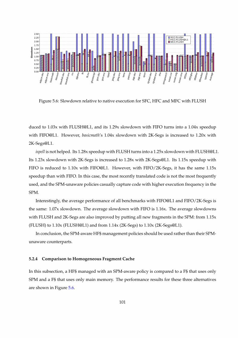
adpc
m.d
ecad
pcm
.enc
basi
cmat
hbi
tcou
ntbl
owfis
h.de
cbl
owfis
h.en
c
crc
dijk
stra fft
fft.in
v
ghos
tscr
ipt
gsm
.dec
gsm
.enc
ispe
ll
jpeg
.dec
jpeg
.enc
lam
e
patr
icia
pgp.
dec
pgp.
enc
qsor
trij
ndae
l.dec
rijnd
ael.e
nc sha
strin
gsea
rch
susa
n.co
rsu
san.
edg
susa
n.sm
otif
f2bw
tiff2
rgba
tiffd
ither
tiffm
edia
n
type
set
Ave
rage
0.00
0.25
0.50
0.75
1.00
1.25
1.50
1.75
2.00
2.25
2.50S
low
do
wn
SCC:FLUSHHCC:FLUSH@L1MCC:FLUSH
Figure 5.6: Slowdown relative to native execution for SFC, HFC and MFC with FLUSH
duced to 1.03x with FLUSH@L1, and its 1.29x slowdown with FIFO turns into a 1.04x speedup
with FIFO@L1. However, basicmath’s 1.04x slowdown with 2K-Segs is increased to 1.20x with
2K-Segs@L1.
ispell is not helped. Its 1.28x speedup with FLUSH turns into a 1.25x slowdown with FLUSH@L1.
Its 1.23x slowdown with 2K-Segs is increased to 1.28x with 2K-Segs@L1. Its 1.15x speedup with
FIFO is reduced to 1.10x with FIFO@L1. However, with FIFO/2K-Segs, it has the same 1.15x
speedup than with FIFO. In this case, the most recently translated code is not the most frequently
used, and the SPM-unaware policies casually capture code with higher execution frequency in the
SPM.
Interestingly, the average performance of all benchmarks with FIFO@L1 and FIFO/2K-Segs is
the same: 1.07x slowdown. The average slowdown with FIFO is 1.16x. The average slowdowns
with FLUSH and 2K-Segs are also improved by putting all new fragments in the SPM: from 1.15x
(FLUSH) to 1.10x (FLUSH@L1) and from 1.14x (2K-Segs) to 1.10x (2K-Segs@L1).
In conclusion, the SPM-aware HF$ management policies should be used rather than their SPM-
unaware counterparts.
5.2.4 Comparison to Homogeneous Fragment Cache
In this subsection, a HF$ managed with an SPM-aware policy is compared to a F$ that uses only
SPM and a F$ that uses only main memory. The performance results for these three alternatives
are shown in Figure 5.6.
101

SFC:FLUSH allocates the F$ to the 4KB SPM and handles overflows with FLUSH, without
resizing. In most cases, the translated code does not fit in the small SPM, leading to unacceptable
slowdowns1. For instance, stringsearch has a 15.09x slowdown, spent mostly in translation – SPM
time is just 0.45x. With HFC:FLUSH@L1, it has a 1.32x speedup. Another example is typeset, which
has a 43.93x slowdown with SFC:FLUSH, but its SPM time is just 0.61x. With HFC:FLUSH@L1, its
slowdown is only 1.32x. When the translated code working set fits in SPM, SFC outperforms the
techniques that execute code in main memory. For instance, crc32 has slowdowns of 1.09x with
SFC:FLUSH and 1.26x with HFC:FLUSH@L1 and MFC:FLUSH.
MFC:FLUSH initially allocates a 16KB F$ to main memory and uses our resizing heuristic to
adaptively increase its size (2K each time). FLUSH is used for evictions. In most cases, the SPM-
aware techniques outperform MFC:FLUSH thanks to their taking better advantage of the SPM.
For instance, fft with MFC:FLUSH has a 1.48x slowdown, but only a 1.34x with HFC:FLUSH@L1.
For ghostscript, MFC: FLUSH does reasonably well: 1.15x speedup. With HFC:FLUSH@L1, it does
much better: 2.70x speedup.
On average, the HFC outperforms both SFC and MFC. HFC:FLUSH@L1 has an average slow-
down of 1.10x, while MFC:FLUSH slowdown is 1.23x. SFC:FLUSH has the worst average slow-
down, 11.41x, because SFC is too small.
Only some benchmarks need the F$ in main memory to grow. Table 5.1 shows the final F$ size
for benchmarks where L2-HFC grows at least by 4KB. HFC size includes the 4KB SPM. Although
no growth limit is set when enabling the resizing heuristic, the amount of main memory needed
for DBT is much less than for native execution. For instance, the final F$ size for ghostscript is less
than 8% the size of the binary’s code segment.
These results show that the HF$ is a good choice for a SoC with heterogeneous memory re-
sources since it can fully use those resources to minimize DBT overhead. However, when the SoC
lacks an I-cache, a different approach should be used to achieve good performance, given that
SFC:FLUSH does not perform well.
1ispell did not run to completion.
102

Table 5.1: Final fragment cache size
Benchmark Binary HFC:FLUSH@L1 MFC:FLUSHghostscript 888K 60K (6.76%) 64K (7.21%)gsm.enc 78K 28K (35.90%) 28K (35.90%)ispell 106K 28K (26.42%) 28K (26.42%)lame 158K 70K (44.30%) 68K (43.04%)patricia 58K 28K (48.28%) 26K (44.83%)pgp.dec 228K 30K (13.16%) 30K (13.16%)pgp.enc 228K 28K (12.28%) 26K (11.40%)typeset 544K 80K (14.71%) 86K (15.81%)
103

5.3 SCRATCHPAD FRAGMENT CACHE MANAGEMENT
Reducing the footprint of the translated code makes it more likely for the translated code working
set to fit in a small F$, i.e., the miss rate of the F$ is reduced by footprint reduction. Despite the
benefit of footprint reduction, the translated code working set of a program may still be too large
to fit in the available SPM, which requires making room in the F$ for new fragments at the expense
of existing fragments.
Typical F$ overflow handling strategies evict one or more fragments from the F$ [48, 49] by
deleting them. When a fragment is prematurely deleted, i.e., if it is needed again for execution
at a later point, the fragment has to be re-translated. During translation, untranslated code is
fetched from external NAND Flash, which has high latency. When fragments are deleted, the cost
of re-translation is similar to the cost of the original translation, so the F$ has a high miss penalty.
This section shows how to reduce the miss penalty of the F$ by memoizing evicted fragments
in a Compressed Victim F$ rather than deleting them. The memoized fragments can be restored to
the F$ faster than re-translating them from external NAND Flash. Also, fragment pinning can be
used to avoid repeatedly evicting and memoizing frequently executed fragments. Pinning reduces
both the miss rate and the miss penalty of a small F$, so it can effectively take advantage of SPM
for DBT.
5.3.1 Victim Compression
FLUSH is a F$ overflow handling strategy that minimizes management cost by simply discarding
the whole contents of the F$ [8]. After F$ flushing, the translator starts refilling the now empty
F$. However, it is likely that some of the fragments that were deleted are needed again soon,
especially with a small F$. When the untransalted code is kept in Flash, a high access cost will be
paid to re-translate these fragments.
StrataX uses a form of victim caching[66] to reduce the high cost of re-translating prematurely
evicted fragments. The FLUSH policy is modified to save the victim fragments rather than delet-
ing them. Since there are as many victims as fragments, the evicted code is compressed. Code
compression minimizes the amount of space needed for the victim fragments. The compres-
sor/decompressor is implemented in software as part of StrataX, without the need for additional
hardware support.
104

StrataX keeps the compressed version of the evicted code in a CVF$. Before starting to build a
new fragment from the untranslated code fetched in NAND Flash, StrataX checks if the CVF$ has
a compressed version of the fragment. If found, the compressed fragment is decompressed from
the CVF$ into the F$. As long as the cost of decompression is less than the cost of retranslating
the fragment from Flash, victim compression will reduce the penalty of re-populating the F$ with
previously translated fragments.
5.3.1.1 Dynamic SPM Partitioning An important design choice is where to place the com-
pressed code; it could be put in external main memory. However, doing so would increase the
footprint of the translated code (compressed and uncompressed) and pollute the data cache dur-
ing compression and decompression. Thus, StrataX allocates the the F$ and CVF$ together in
the SPM, which ensures that the total space needed to store the translated code is not increased
beyond the original F$ size.
This leads to another important design question: how to partition the SPM among compressed
and uncompressed code. One possibility is to do a fixed partition, i.e., to assign a portion of the
SPM exclusively to the CVF$. However, this scheme would reduce the capacity of the F$ since it
will no longer be able to use the entire SPM. As a result, F$ pressure will be greater and perfomance
is likely to degrade significantly.
Rather than statically partitioning the SPM among the F$ and the CVF$, StrataX uses a dy-
namic partitioning scheme. The dynamic scheme addresses the limitations of the fixed scheme by
allowing the F$ and CVF$ to expand and contract dynamically in order to better utilize the SPM.
The steps of the dynamic partitioning scheme are illustrated in Figure 5.7. In the first step,
there is no compressed code and the F$ occupies the entire SPM. In the second step, when the F$
overflows, all fragments are compressed and the CVF$ is allocated at the highest SPM address,
while the F$, which starts at the lowest SPM address, is shrunk to leave room in SPM for the
compressed code. In the third step, the CVF$ and Flash memory are used to retrieve previous
fragments and application code to form new fragments. In the fourth step, when the shrunken F$
gets full, the CVF$ is deallocated and its space is used to expand the F$ again over the entire SPM.
Any new application addresses fetched by the translator will come from Flash. These steps are
repeated throughout program execution.
The advantage to the dynamic partitioning scheme is that the F$ can occupy the entire SPM
when necessary, without sacrificing its effective capacity. However, the disadvantage is that the
105

Fragments
CompressedFragments
FragmentsFragments
FreeSpace
Fragments
FreeSpace
CompressedFragments
(1) Translate (2) Overflow:Compress Victims
(3) Translate &Decompress
(4) Overflow:Evict Victims
Figure 5.7: Victim compression and space reclamation
CVF$ captures only the most recently flushed victim fragments.
5.3.1.2 Compression and Decompression A software-only implementation of the CodePack [68]
algorithm is used to compress and decompress victim fragments. CodePack has a good compres-
sion ratio (about 50%) and performance when implemented in software. StrataX’s CodePack is
adapted to accommodate PISA and to avoid aligning the starting point of compressed code to
word boundaries (so it minimizes the footprint of the compressed code in the CVF$). The im-
plementation is configurable to support other compression algorithms. The inclusion of other
algorithms does not change the process outlined in Figure 5.8.
Figure 5.8 shows how compression and decompression are integrated with the DBT process in
StrataX. The shaded region in the upper right corner of the figure is the compression loop. The
loop is entered when the F$ is flushed. The decompression loop is in the lower right corner. It is
entered when a requested application address is not found in the F$ but in the CVF$.
The compression loop is entered when the F$ is flushed. On a flush, the F$ is traversed to
remove control code from the victim fragments. Control code is not compressed since it can be
regenerated when the fragment is decompressed. In fact, CTI targets in control code depend on
106

Figure 5.8: Incorporating compression and decompression
the F$ layout and may be different after re-translation. Next, two dictionaries are constructed: one
dictionary (csym), is used for compression and the other (dsym) is used for decompression.
Once the dictionaries are constructed, the victim fragments are compressed into the CVF$.
For decompression, it is necessary to know which application addresses are in the CVF$. The
compressor builds a victim fragment map (cfMap ) that relates application addresses to their cor-
responding compressed fragments. csym is discarded after compression. cfMap and dsym are
persistent and stored in external SDRAM as data. They are accessed during decompression.
The decompression loop is entered when the translator fetches a new application address. On
a fetch, the translator checks whether that address is held in the CVF$. A lookup is done in cfMap
to see whether there is a compressed fragment for the application address. If so, the fragment is
decompressed and the control code needed by the translator is generated.
5.3.1.3 Evaluation With the dynamic SPM partitioning scheme, the F$ is flushed as many times
as when only FLUSH is used. Because the compressed code is discarded to expand the F$ when it
needs more space, theF$ effectively has the same capacity as when no CVF$ is used. The benefit to
victim compression will show as an improvement in performance by avoiding accesses to Flash.
Table 5.2 shows performance without (FLUSH) and with victim compression (COMPR.). When
107

Table 5.2: Speedup (slowdown) with victim compression
FLUSH COMPR.basicmath (1.5) (1.4)fft (1.03) 1.0fft-inverse (1.1) 1.1ghostscript (8.4) (4.5)gsm-decode 1.9 1.9gsm-encode (11.2) (3.3)jpeg-decode 3.1 3.2jpeg-encode 2.1 2.5lame (185.6) (158.8)susan-edges 2.9 3.0tiff2bw (3.3) (3.7)tiff2rgba 3.1 3.5tiffdither 1.7 1.9tiffmedian 2.0 2.3
a program suffers at least one F$ overflow, there is a potential improvement over FLUSH by mem-
oizing the victims. For example, fft and jpeg-decode have the same number of flushes without and
with victim compression. Their performance is improved since the accesses to Flash are avoided
when evicted code is needed again. This result also shows that there is code reuse across F$
flushes. Indeed, when a program has many flushes and there is much reuse, victim compression
is especially beneficial. For example, ghostscript has a 8.4x slowdown with FLUSH and a 4.5x
slowdown with victim compression. In this program, some code is evicted for a short period
and reused later, possibly after more than one FLUSH has occurred. Another interesting case is
fft-inverse, where an initial 1.1x slowdown is improved to a 1.1x speedup.
5.3.2 Fragment Pinning
While victim compression avoids fetching and re-translating previously encountered code, it still
suffers overhead. For a small F$, it is possible that the same fragment may be evicted, compressed,
and decompressed many times, incurring unnecessary overhead. To prevent this pathological
case, StrataX uses fragment pinning, i.e., it locks a frequently used fragment to the F$. When a
fragment is pinned, it is not evicted on a flush but remains as executable code. Thus, it will not
incur multiple compression and decompression cycles.
108

In StrataX, pinned and unpinned fragments share the F$. A pinning strategy decides what
fragments to pin, when to pin them, and when to release the pins. Only unpinned fragments are
compressed into the CVF$ when handling a F$ overflow.
5.3.2.1 Pinning and Release Strategies There are many possible pinning strategies. One strat-
egy might count fragment execution frequency to pin hot fragments. Counters could also be used
to determine when to release a cold pinned fragment. However, these strategies have monitoring
overhead, either done with instrumentation (which occupies F$ space) or hardware counters.
StrataX takes advantage of the fact that the CVF$ holds recent victims. When an application
address is needed and a corresponding fragment is found in the CVF$, that fragment is likely
part of the current working set. When a needed fragment is in the CVF$, it is decompressed and
pinned. Thus, the only fragments that can be pinned are victims from a previous F$ flush. A pin is
acquired as soon as a needed fragment is found in the CVF$.
The pins are released when the size of the percentage of pinned fragments in th F$ reaches a
“release threshold” ratio, i.e., when sizeof(pinned)sizeof(pinned)+sizeof(unpinned) ≥ threshold. The intuition is that
a working set change is most likely when there is pressure in the F$ for new (unpinned) fragments.
The pins are released so that the contents of the F$ do not become stale. This strategy is simple
and inexpensive because it does not need monitoring.
Two release strategies are studied for StrataX: releasing all pins at once (akin to FLUSH), or
releasing only the least recently created pins until the percentage of pinned fragments is again
below a threshold (akin to FIFO). Releasing all pins may lead to some premature releases if the
fragments are still needed. Releasing pins in FIFO order to maintain a threshold increases man-
agement overhead, but may save compress and decompress cycles for fragments that are still
needed.
Figure 5.9 illustrates StrataX’s pinning strategy as a state machine. The diagram shows the
states that a fragment goes through and the transitions that cause a state change. Initially, an
application address is in the untranslated state. When the address is fetched, a fragment is created
and saved in the F$. If the F$ is flushed, the fragment is saved in a compressed state in the
CVF$. When the address is requested again, the corresponding fragment is transitioned from
a compressed state to a pinned state in the F$. The pin will be released when the percentage
of pinned fragments in the F$ is above the threshold ratio. CVF$ space reclamation causes all
compressed code to be transitioned to the untranslated state.
109

Figure 5.9: Fragment state diagram with pinning
5.3.2.2 Evaluation Because fragment pinning benefits programs with more than one F$ flush,
only such programs are considered in evaluating the benefit of pinning.
We investigated how fragment pinning helps reduce F$ flushes. Table 5.3 shows the number of
flushes without and with fragment pinning. In the table, “COMPR.” is victim compression with
variable region partitioning and “Pin-ALL” is compression with pinning and the release all pins
at once strategy. “Pin-FIFO” is compression with pinning and the pins released in FIFO order
to stay under threshold. In both Pin-ALL and Pin-FIFO, the pin release threshold is 50%. After
experimenting with several thresholds, 50% did the best on average.
Fragment pinning can reduce flushes. For example, in ghostscript, the number of flushes
changes from 489 with compression to 196 with Pin-ALL. When FIFO information is used (Pin-
FIFO), there is only one flush. After the F$ is flushed once, there will always be at least one pinned
fragment in the F$ with this strategy. Thus, Pin-FIFO never flushes the entire F$ again. The F$ may
continue to overflow its boundaries, causing the CVF$ space to be reclaimed.
Table 5.4 gives performance with pinning. For ghostscript, there is a 3.6x slowdown with Pin-
FIFO and 4.5x with COMPR. Pin-ALL, on the other hand, increases the slowdown for ghostscript
because older, unneeded fragments are kept pinned, which is avoided by Pin-FIFO. gsm-encode
also has a particularly good improvement with pinning: It has a 3.3x slowdown with just COMPR.
and only a 1.1x slowdown with Pin-FIFO. The slowdown for gsm-encode is improved enough to
be competitive with traditional memory shadowing. These results show that pinning is good at
preventing premature fragment evictions, reducing the overall re-translation cost.
110

Table 5.3: Number of flushes without and with fragment pinning
COMPR. Pin-ALL Pin-FIFOghostscript 489 196 1gsm-encode 88 16 1jpeg-decode 2 1 1jpeg-encode 2 1 1lame 2320 235 1tiffdither 3 2 1tiffmedian 2 1 1
5.3.3 Overall Improvement
Figure 5.10 shows the performance improvement for all benchmarks and SPM sizes when foot-
print reduction, victim compression and pinning (PinFIFO, 50% threshold) are enabled. The figure
shows performance from Figure 4.1 for comparison.
StrataX techniques improve performance across the SPM sizes, particularly when the trans-
lated code working set does not initially fit in the F$. For example, in dijkstra for SP-16KB, per-
formance is improved from a 15.8x slowdown to a 2.2x speedup. gsm-encode has an impressive
improvement for SP-32KB. It initially has a slowdown of 938.3x due to thrashing; with StrataX, its
slowdown is reduced to 1.1x because it no longer thrashes. These results also show that StrataX
techniques usually do not degrade performance when unneeded. For example, adpcm-decodeis a
tight loop that fits in all SPM sizes and its speedup is 1.9x in all cases.
Even with StrataX techniques, some programs still have large runtime overheads. lame has
this behavior. With SP-32KB, it has an initial slowdown of 258.7x and a final slowdown of 114.3x.
lame’s working set does not fully fit in the F$. Although Pin-FIFO reduces full flushes to one, the
F$ still overflows and there are many accesses to Flash memory. ghostscript behaves similarly, but
the effect is not as dramatic.
On average, footprint reduction, victim compression and pinning, have an initial speedup of
1.9x (SP-64KB), 1.6x (SP-32KB), and 0.9x (SP-16KB) over memory shadowing. With our techniques,
these average speedups are improved to 2.2x (SP-64KB), 2.1x (SP-32KB) and 1.9x (SP-16KB).
In comparison to Mem-2MB, a 32KB fragment cache allocated to SPM (i.e., SP-32KB) has
slightly better performance. Mem-2MB has an average speedup of 2.06x and SP-32KB has an av-
erage speedup of 2.1x. The total amount of memory needed for the F$ is much less with SP-32KB
111

Table 5.4: Speedup (slowdown) with fragment pinning
COMPR. Pin-ALL Pin-FIFOghostscript (4.5) (5.6) (3.6)gsm-encode (3.3) (3.1) (1.1)jpeg-decode 3.2 3.2 3.2jpeg-encode 2.5 2.5 2.5lame (158.8) (143.1) (114.3)tiffdither 1.9 1.9 2.0tiffmedian 2.3 2.3 2.3
than Mem-2MB, yet its performance is better than Mem-2MB.
These results show that StrataX is effective in enabling the use of DBT in embedded systems
with a small SPM.
112

Figure 5.10: Final vs. Initial Speedup for 64KB, 32KB and 16KB fragment caches
113
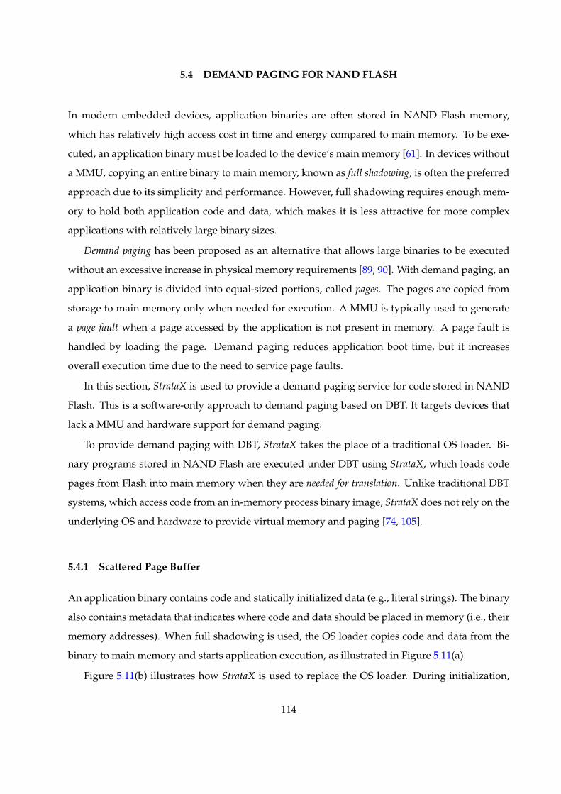
5.4 DEMAND PAGING FOR NAND FLASH
In modern embedded devices, application binaries are often stored in NAND Flash memory,
which has relatively high access cost in time and energy compared to main memory. To be exe-
cuted, an application binary must be loaded to the device’s main memory [61]. In devices without
a MMU, copying an entire binary to main memory, known as full shadowing, is often the preferred
approach due to its simplicity and performance. However, full shadowing requires enough mem-
ory to hold both application code and data, which makes it is less attractive for more complex
applications with relatively large binary sizes.
Demand paging has been proposed as an alternative that allows large binaries to be executed
without an excessive increase in physical memory requirements [89, 90]. With demand paging, an
application binary is divided into equal-sized portions, called pages. The pages are copied from
storage to main memory only when needed for execution. A MMU is typically used to generate
a page fault when a page accessed by the application is not present in memory. A page fault is
handled by loading the page. Demand paging reduces application boot time, but it increases
overall execution time due to the need to service page faults.
In this section, StrataX is used to provide a demand paging service for code stored in NAND
Flash. This is a software-only approach to demand paging based on DBT. It targets devices that
lack a MMU and hardware support for demand paging.
To provide demand paging with DBT, StrataX takes the place of a traditional OS loader. Bi-
nary programs stored in NAND Flash are executed under DBT using StrataX, which loads code
pages from Flash into main memory when they are needed for translation. Unlike traditional DBT
systems, which access code from an in-memory process binary image, StrataX does not rely on the
underlying OS and hardware to provide virtual memory and paging [74, 105].
5.4.1 Scattered Page Buffer
An application binary contains code and statically initialized data (e.g., literal strings). The binary
also contains metadata that indicates where code and data should be placed in memory (i.e., their
memory addresses). When full shadowing is used, the OS loader copies code and data from the
binary to main memory and starts application execution, as illustrated in Figure 5.11(a).
Figure 5.11(b) illustrates how StrataX is used to replace the OS loader. During initialization,
114
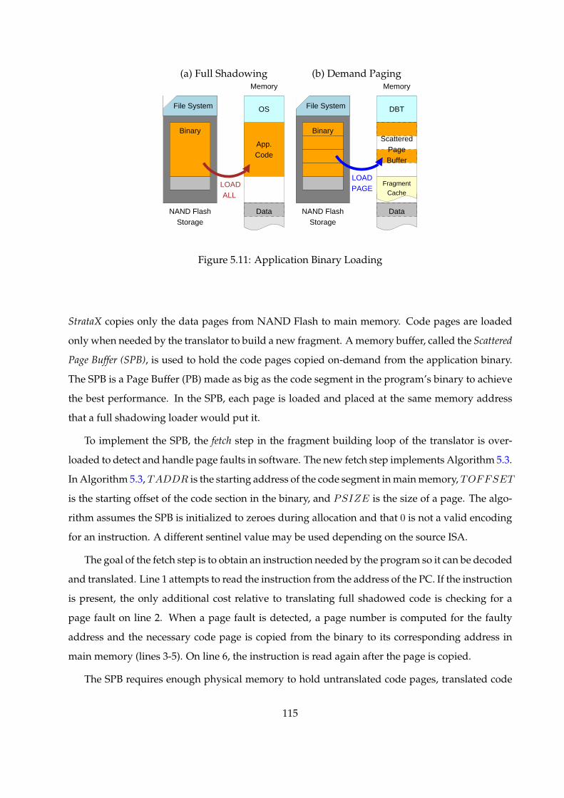
(a) Full Shadowing (b) Demand Paging
File System
NAND FlashStorage
Memory
App.Code
Binary
LOADALL
OS
Data
File System
NAND FlashStorage
DBT
Memory
BinaryScattered
PageBuffer
LOAD PAGE
Data
FragmentCache
Figure 5.11: Application Binary Loading
StrataX copies only the data pages from NAND Flash to main memory. Code pages are loaded
only when needed by the translator to build a new fragment. A memory buffer, called the Scattered
Page Buffer (SPB), is used to hold the code pages copied on-demand from the application binary.
The SPB is a Page Buffer (PB) made as big as the code segment in the program’s binary to achieve
the best performance. In the SPB, each page is loaded and placed at the same memory address
that a full shadowing loader would put it.
To implement the SPB, the fetch step in the fragment building loop of the translator is over-
loaded to detect and handle page faults in software. The new fetch step implements Algorithm 5.3.
In Algorithm 5.3, TADDR is the starting address of the code segment in main memory, TOFFSET
is the starting offset of the code section in the binary, and PSIZE is the size of a page. The algo-
rithm assumes the SPB is initialized to zeroes during allocation and that 0 is not a valid encoding
for an instruction. A different sentinel value may be used depending on the source ISA.
The goal of the fetch step is to obtain an instruction needed by the program so it can be decoded
and translated. Line 1 attempts to read the instruction from the address of the PC. If the instruction
is present, the only additional cost relative to translating full shadowed code is checking for a
page fault on line 2. When a page fault is detected, a page number is computed for the faulty
address and the necessary code page is copied from the binary to its corresponding address in
main memory (lines 3-5). On line 6, the instruction is read again after the page is copied.
The SPB requires enough physical memory to hold untranslated code pages, translated code
115

1: instruction← ∗(PC)2: if instruction = 0 then {software page fault}3: page← (PC − TADDR)/PSIZE4: lseek(bfd, TOFFSET + page ∗ PSIZE, 0)5: read(bfd, TADDR + page ∗ PSIZE, PSIZE)6: instruction← ∗(PC)7: end if
Algorithm 5.3: Fetch step with scattered page buffer
and data. Demand paging with DBT improves the application’s boot time since application execu-
tion starts just after reading the first page and forming the first fragment. Only pages containing
executed code are loaded, while full shadowing may load pages that are never executed. Loading
only the pages containing executed code reduces total load time, which helps to amortize the time
spent doing translation.
5.4.1.1 Evaluation To evaluate demand paging provided with StrataX, the simulator is com-
piled to resemble an ARM1176JZ(F)-S SoC, according to Table 3.5. StrataX can provide direct
execution with full shadowing, by loading the application binary into main memory and imme-
diately “bailing out”, i.e., transferring control to the original code without doing any DBT. The
simulator measures boot time, total execution time and the number of Flash page reads.
DBT-based demand paging with an SPB reduces the number of NAND Flash page reads by 31% on
average, relative to full shadowing (FS). The number of NAND Flash pages read when executing
the MiBench programs is shown in Table 5.5. The page count includes both data and code pages.
Some applications benefit more from demand paging than others. For instance, ghostscript has
a 53% reduction (from 2047 to 971 page reads). It contains code to produce its output in several
formats, but only one format is requested in a single execution, so many of its code pages are never
accessed. On the other hand, applications like basicmath and patricia, have only a small reduction
(respectively, 2% and 5%) because most of their pages are executed.
DBT-based demand paging with the SPB also reduces application boot time (i.e., the time until
the first program instruction is executed) by at least 50%. This benefit can be observed in Fig-
ure 5.12, which shows the boot time of the MiBench programs for DBT with SPB (DBT/SPB), as a
percentage of their boot time for direct execution with full shadowing (DE/FS). The smallest boot
116

Table 5.5: NAND Flash pages read (512 bytes/page)
Program FS SPB Program FS SPBadpcm.dec 81 53 patricia 116 110adpcm.enc 81 53 pgp.dec 524 318basicmath 103 101 pgp.enc 524 290bitcount 86 62 qsort 113 79blowfish.dec 98 55 rijndael.dec 152 102blowfish.enc 98 55 rijndael.enc 152 103crc 83 58 rsynth 243 192dijkstra 110 73 sha 84 57fft 92 80 stringsearch 115 79fft.inv 92 81 susan.cor 149 88ghostscript 2047 971 susan.edg 149 95gsm.dec 185 122 susan.smo 149 82gsm.enc 185 142 tiff2bw 509 374ispell 236 164 tiff2rgba 570 375jpeg.dec 277 168 tiffdither 507 397jpeg.enc 253 161 tiffmedian 517 368lame 470 391 typeset 1230 909
time reduction is 50%, for tiff2bw and tiffdither. typeset has the largest reduction to just 13.5% of the
initial boot time. ghostscript has a new boot time equivalent to 14.4% of the initial boot time.
To achieve good performance when executing a program with DBT, the time spent in trans-
lation must be amortized by a reduction in other components of the overall execution time. Our
DBT-based demand paging technique amortizes translation time by reducing the number of ex-
pensive NAND Flash page reads needed to load application code into memory. However, since
the code is not optimized beyond being relocated to the fragment cache (without never taken CTI
targets), the overall performance may not be improved. The translated code has a different layout
than the original code, so it has different interaction with microarchitectural features such as the
branch predictor and the caches.
When using the SPB, StrataX has a modest 1.03x average speedup relative to direct execution with
full shadowing. Figure 5.13 shows the speedup for the MiBench programs. The overall execution
time includes the time spent in loading, translation (for DBT only) and application code execu-
tion. The majority of the MiBench programs have better performance with DBT/SPB than with
DE/FS. The highest speedups are for pgp-sign (1.41x), jpeg-decode (1.24x), pgp-verify (1.24x) and
susan-corners (1.24x). A few programs suffer significant performance loss, such as bitcount with
117

adpc
m.d
ecad
pcm
.enc
basi
cmat
hbi
tcou
ntbl
owfis
h.de
cbl
owfis
h.en
ccr
cdi
jkst
ra fftfft
.inv
ghos
tscr
ipt
gsm
.dec
gsm
.enc
ispe
lljp
eg.d
ecjp
eg.e
ncla
me
patr
icia
pgp.
dec
pgp.
enc
qsor
trij
ndae
l.dec
rijnd
ael.e
ncrs
ynth
sha
strin
gsea
rch
susa
n.co
rsu
san.
edg
susa
n.sm
otif
f2bw
tiff2
rgba
tiffd
ither
tiffm
edia
nty
pese
t0%
10%
20%
30%
40%
50%
60%
Bo
ot
Tim
e
SPB
Figure 5.12: Boot time with DBT/SPB relative to DE/FS
118

adpc
m.d
ecad
pcm
.enc
basi
cmat
hbi
tcou
ntbl
owfis
h.de
cbl
owfis
h.en
ccr
cdi
jkst
ra fftfft
.inv
ghos
tscr
ipt
gsm
.dec
gsm
.enc
ispe
lljp
eg.d
ecjp
eg.e
ncla
me
patr
icia
pgp.
dec
pgp.
enc
qsor
trij
ndae
l.dec
rijnd
ael.e
ncrs
ynth
sha
strin
gsea
rch
susa
n.co
rsu
san.
edg
susa
n.sm
otif
f2bw
tiff2
rgba
tiffd
ither
tiffm
edia
nty
pese
tA
vera
ge
0.5
0.6
0.7
0.8
0.9
1.0
1.1
1.2
1.3
1.4
1.5
Sp
eed
up
SPB
Figure 5.13: Speedup with DBT/SPB relative to DE/FS
119

Free SpaceFree Space
Fragments
UntranslatedPages
Fragments Fragments
UntranslatedPages
UntranslatedPages
(1) Load & Translate (2) Overflow: Evict Page
lowaddress
highaddress
Figure 5.14: Unified Code Buffer
a 1.72x slowdown (highest), quicksort with 16% overhead, typeset with 10% overhead, and rsynth
with 8% overhead. All other programs have 5% or less overhead, or a speedup.
These results indicate that DBT-based demand-paging provided can be more effective in MMU-
less embedded systems than direct execution with full shadowing. It always reduces the boot time
of the MiBench programs, and improves the overall performance in most of them. However, the
SPB is not enough to reduce memory consumption, which is the motivation for demand paging.
5.4.2 Unified Code Buffer
Executing code under DBT increases memory usage since the original code pages are treated as
data and the application code that is actually executed, i.e., translated code, is held in the F$.
Both the SPB and the F$ consume system memory, likely doubling the memory usage relative
to hardware-based demand paging. This is due to the F$ being made big enough to contain all
translated code. However, to better control the increase in memory pressure due to DBT, StrataX
can combine the SPB and the F$ into a single memory buffer, called the Unified Code Buffer (UCB).
Figure 5.14 illustrates the organization and management of the UCB. The UCB has a fragment
portion that starts at its lowest address and grows towards its highest address, and an untranslated
120
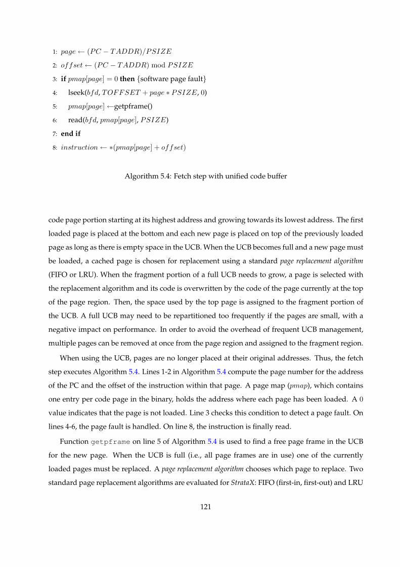
1: page← (PC − TADDR)/PSIZE
2: offset← (PC − TADDR) mod PSIZE
3: if pmap[page] = 0 then {software page fault}4: lseek(bfd, TOFFSET + page ∗ PSIZE, 0)
5: pmap[page]←getpframe()
6: read(bfd, pmap[page], PSIZE)
7: end if
8: instruction← ∗(pmap[page] + offset)
Algorithm 5.4: Fetch step with unified code buffer
code page portion starting at its highest address and growing towards its lowest address. The first
loaded page is placed at the bottom and each new page is placed on top of the previously loaded
page as long as there is empty space in the UCB. When the UCB becomes full and a new page must
be loaded, a cached page is chosen for replacement using a standard page replacement algorithm
(FIFO or LRU). When the fragment portion of a full UCB needs to grow, a page is selected with
the replacement algorithm and its code is overwritten by the code of the page currently at the top
of the page region. Then, the space used by the top page is assigned to the fragment portion of
the UCB. A full UCB may need to be repartitioned too frequently if the pages are small, with a
negative impact on performance. In order to avoid the overhead of frequent UCB management,
multiple pages can be removed at once from the page region and assigned to the fragment region.
When using the UCB, pages are no longer placed at their original addresses. Thus, the fetch
step executes Algorithm 5.4. Lines 1-2 in Algorithm 5.4 compute the page number for the address
of the PC and the offset of the instruction within that page. A page map (pmap), which contains
one entry per code page in the binary, holds the address where each page has been loaded. A 0
value indicates that the page is not loaded. Line 3 checks this condition to detect a page fault. On
lines 4-6, the page fault is handled. On line 8, the instruction is finally read.
Function getpframe on line 5 of Algorithm 5.4 is used to find a free page frame in the UCB
for the new page. When the UCB is full (i.e., all page frames are in use) one of the currently
loaded pages must be replaced. A page replacement algorithm chooses which page to replace. Two
standard page replacement algorithms are evaluated for StrataX: FIFO (first-in, first-out) and LRU
121

(least recently used). Unlike traditional hardware-based demand paging, LRU is defined in terms
of memory accesses done for translation rather than memory accesses done for execution. Since it
is difficult to ensure that a page is no longer needed, performance may degrade if a replaced page
needs to be loaded again.
5.4.2.1 Evaluation Compared to an SPB with an unbounded F$, the UCB adds two major sources
of performance overhead: additional NAND Flash page reads due to premature page replace-
ments (i.e., replacing a page that is needed again for translation) and UCB repartitioning. The
change in the fetch algorithm has no significant impact in performance.
For evaluation, the size of the UCB is set to 75% the code size with full shadowing, i.e., 75%
the size of the code section in the application binary. To avoid frequent UCB repartitioning, the
amount of memory added to the fragment region each time the UCB is repartitioned is set to 5%
the code size with full shadowing.
First, it is necessary to choose a page replacement algorithm. LRU has a higher management
cost than FIFO, since the page replacement order has to be updated not only when the page is
loaded, but also every time the translator accesses it. However, this cost is unimportant when
compared to the time spent reloading a prematurely replaced page. To determine which page
replacement algorithm (FIFO or LRU) works best for the UCB, the number of page reads made
with each algorithm is compared.
Table 5.6 shows the number of NAND Flash page reads made with both algorithms when the
size of the UCB is 75% of the code size with full shadowing. The results indicate that LRU is often
better than FIFO. FIFO has less page reads than LRU in only 7 programs, but LRU has less page
reads in 20 programs. Thus, LRU in used with a UCB in StrataX to provide demand paging.
Figure 5.15 shows the effect of varying the UCB size. The figure shows the speedup with
UCB (DBT/UCB), relative to direct execution with full shadowing (DE/FS). The SPB results are
included to facilitate comparison. The UCB size limits are set to 175%, 75% and 50% the code size
with full shadowing. With the 175% limit, the programs need no additional NAND Flash page
reads than with SPB. With the 50% limit, some programs could not run to completion because the
available memory is not enough to support the growth of the fragment region (e.g., basicmath).
StrataX’s F$ management techniques are not used in this case to avoid introducing the overhead
proper to DBT in the evaluation of the UCB.
The cost of managing the UCB can be significant, as observed in typeset, where the initial
122

Table 5.6: NAND Flash pages read with UCB-75%
Program FIFO LRU Program FIFO LRUadpcm.dec 56 55 patricia 153 154adpcm.enc 58 54 pgp.dec 329 324basicmath 174 173 pgp.enc 292 291bitcount 73 73 qsort 94 91blowfish.dec 55 56 rijndael.dec 107 104blowfish.enc 55 56 rijndael.enc 107 104crc 66 64 rsynth 232 236dijkstra 87 85 sha 70 67fft 124 120 stringsearch 80 80fft.inv 125 131 susan.cor 91 89ghostscript 971 971 susan.edg 103 100gsm.dec 128 129 susan.smo 82 82gsm.enc 176 175 tiff2bw 374 374ispell 183 189 tiff2rgba 375 375jpeg.dec 187 183 tiffdither 412 409jpeg.enc 188 185 tiffmedian 368 368lame 534 529 typeset 1052 1045
overhead of 10% with a SPB increases to 12% with a UCB sized at 175% the code size with full
shadowing. When the limit is set to 75%, typeset makes 136 additional NAND Flash page reads,
and its overhead increases to 15%. A similar trend can be appreciated in jpeg-decode, where the
speedup is reduced from 1.24x with SPB to 1.19x with UCB-175%, 1.14x UCB-75% and 1.03x with
UCB-50%.
The average speedups are 1.02x with UCB-175% and 1.01x with UCB-75%. This results show
that the UCB suffers little average performance loss relative to SPB and it is an effective method for
limiting code memory consumption with DBT.
5.4.3 Asynchronous Loading
StrataX can further reduce execution time by overlapping Flash read time with translated code
execution. This is achieved by initiating an asynchronous Flash page read using the Flash memory
controller. The Flash memory controller can load the page to main memory while the Central
Processing Unit (CPU) executes other code. With StrataX, a code page loaded in a UCB page
frame is accessed during translation but not when the translated code executes.
123

adpc
m.d
ecad
pcm
.enc
basi
cmat
hbi
tcou
ntbl
owfis
h.de
cbl
owfis
h.en
ccr
cdi
jkst
ra fft
fft.in
vgh
osts
crip
tgs
m.d
ecgs
m.e
ncis
pell
jpeg
.dec
jpeg
.enc
lam
epa
trici
apg
p.de
cpg
p.en
cqs
ort
rijnd
ael.d
ecrij
ndae
l.enc
rsyn
thsh
ast
rings
earc
hsu
san.
cor
susa
n.ed
gsu
san.
smo
tiff2
bwtif
f2rg
batif
fdith
ertif
fmed
ian
type
set
Aver
age
0.5
0.6
0.7
0.8
0.9
1.0
1.1
1.2
1.3
1.4
1.5S
pee
du
p
SPB UCB-175% UCB-75% UCB-50%
Figure 5.15: Speedup of DBT/UCB relative to DE/FS
To exploit asynchronous page loading, the fragment linking stage in StrataX is modified. When
a new fragment has been translated, StrataX performs consults the fragment map to determine if
any of the fragment’s CTI targets are already present. If found, the new fragment is proactively
linked to the target fragment to save the cost of a context switch, otherwise, a trampoline is emit-
ted. In addition to emitting the trampoline, the page table is checked to determine if the page
containing the untranslated code for the target fragment is present. If not, an asynchronous page
read for that page is started. StrataX then starts executing the new fragment just created. The fetch
step is also modified to check if the page with the untranslated code is being loaded. In that case,
the fetch step waits until the asyncronous read finishes.
5.4.3.1 Evaluation Figure 5.16 shows the speedup of the MiBench programs when pages are
loaded asynchronously and in parallel with translated code execution. The technique is very
effective in “hiding” page loading overhead. It improves the speedup for every benchmark. For
instance, stringsearch goes from 1.18x speedup to 3.73x speedup, and pgp-sign goes from 1.35x
speedup to 3.43x speedup! High speedup improvements are obtained also for jpeg-decode (1.14x
to 2.44x), pgp-verify (1.18x to 2.29x) and susan-corners (1.19x to 2.11x). All of these benchmarks
execute at least twice as fast with asynchronous demand paging provided with DBT than with
full shadowing.
124

adpc
m.d
ecad
pcm
.enc
basi
cmat
hbi
tcou
ntbl
owfis
h.de
cbl
owfis
h.en
ccr
cdi
jkst
ra fftfft
.inv
ghos
tscr
ipt
gsm
.dec
gsm
.enc
ispe
lljp
eg.d
ecjp
eg.e
ncla
me
patr
icia
pgp.
dec
pgp.
enc
qsor
trij
ndae
l.dec
rijnd
ael.e
ncrs
ynth
sha
strin
gsea
rch
susa
n.co
rsu
san.
edg
susa
n.sm
otif
f2bw
tiff2
rgba
tiffd
ither
tiffm
edia
nty
pese
tA
vera
ge
0.5
0.6
0.7
0.8
0.9
1.0
1.1
1.2
1.3
1.4
1.5
1.6
1.7
1.8
1.9
2.0
2.1
2.2
2.3
2.4
2.5
2.6
2.7
2.8
2.9
3.0
3.1
3.2
3.3
3.4
3.5
3.6
3.7
3.8
Sp
eed
up
UCB-75%-Sync UCB-75%-Async
Figure 5.16: Speedup with asynchronous Flash page reads
125

bitcount does not get significant benefit from asynchronous demand paging. The reason is that
load time dominates over translation and execution time, and it is not possible to “hide” load
time by parallelizing it with translated code execution. quicksort also gets little benefit from the
technique.
However, the majority of programs do receive a benefit. Except for quicksort and bitcount, all
the other benchmarks have above 0.95x speedup, with an average speedup of 1.33x.
126
6.0 CONCLUSIONS AND FUTURE WORK
DBT has demonstrated potential to address many issues of concern in modern embedded sys-
tems (e.g., platform emulation, JIT compilation, power management, secure code execution, etc.).
However, these techniques have been mostly applied in general-purpose systems without the
constraints of embedded systems (performance, memory capacity, real-time guarantees, energy
consumption, user privacy and security). In embedded systems, DBT use has been limited due to
performance, memory and power overhead.
This thesis addresses the challenges presented by embedded systems to DBT through novel
techniques (e.g. incremental loading, footprint reduction, heterogeneous fragment cache). It is the
first work to enable the use of DBT in embedded systems with SPM. The techniques have been
incorporated into an extensible framework and research infrastructure, called StrataX, which can
be used for further study of the enabling techniques and to provide new DBT-based services for
embedded systems. Experiments validate that DBT can have “good enough” base performance
when using SPM to reduce performance overhead and allow the enabling of useful services for
embedded systems.
6.1 SUMMARY OF CONTRIBUTIONS
This thesis contributes to the adoption of DBT as a basic system-level technology in the embed-
ded computing domain. It solves important problems (e.g., transparent SPM management) and
enables opportunities for future research and development in the areas of dynamic binary trans-
lation, embedded systems, and operating systems. This thesis makes the following contributions:
1. This thesis identifies code expansion as a major challenge in providing low-overhead DBT
for embedded systems. It shows the causes of expansion to be duplication and speculation
127

during fragment formation and the insertion of excessive “control code”. Thus, the fragment
formation policy has been experimentally tuned and “control code” has been re-designed to
make the footprint of the translated code more likely to fit in a small F$ allocated to SPM.
A thorough evaluation of the performance impact of different designs and comparison with
alternatives is among the contributions of this thesis.
2. This thesis contributes the HF$, a new kind of F$ allocated on heterogeneous memory re-
sources, i.e., SPM and main memory accessed through a hardware instruction. The contri-
butions include several HF$ management policies that transparently partition translated code
among SPM and main memory. Previous SPM allocation solutions require compile-time sup-
port or custom binary modifications. The techniques in this thesis do not require in-advance
knowledge of SPM size and eliminate the need for custom binaries tied to an specific resource
configuration or carrying profile information.
3. When the translated code working set does not fit in a small F$ allocated to SPM, DBT overhead
is increased due to premature fragment evictions and re-translation. This thesis contributes
novel F$ management policies for reducing this additional overhead, i.e., victim compression
and fragment pinning.
4. A DBT-based demand paging service for code has been developed to reduce the memory
requirements and boot time of DBT-controlled applications in embedded systems without a
MMU. This demand paging service uses a UCB to keep untranslated code pages and trans-
lated code (fragments), which provides fine control over code memory consumption. By per-
forming asynchronous page loads into the UCB, the overall execution time of a DBT-controlled
application is further reduced.
5. A framework for research and development of DBT-based services for embedded systems that
incorporates all the techniques described in this dissertation has been developed. This frame-
work allows the study of DBT on a simulated embedded SoC. It includes two software arti-
facts: StrataX, a new DBT infrastructure for memory-constrained embedded systems; and a
SoC simulator with extensive support for DBT based on SimpleScalar.
128

6.2 FUTURE WORK
There are multiple research problems along the lines of this dissertation that could be explored
with the help of StrataX. Some of them are described below.
1. Many embedded systems have to meet real-time constraints that make incorporating DBT
more challenging. In particular, translation and translated code execution must be carefully
interleaved in time to ensure that the real-time constraints are met. The simulation framework
contributed by this thesis helps identifying translation and translated code execution, so it can
help in developing new policies for scheduling translation and translated code execution. This
experimental approach could complement traditional worst-case execution time analysis as a
means for providing DBT-based services to programs with real-time constraints.
2. DBT could provide a lightweight runtime solution for multi-programming in SoCs. To do so,
StrataX can be extended to handle multiple programs at a time to study the effects of DBT-
based services applied to multiple programs. StrataX could provide “green threads”, i.e.,
threads scheduled by the virtual machine rather than by the host OS. Threads could belong
to a single program, or to different application programs. This exposes opportunities for code
sharing and for providing novel DBT-based services, e.g., StrataX could translate library code
for one program and share it with another program. Furthermore, this library code could be
distributed in encrypted form to protect IP, and StrataX could safely decrypt it on-demand into
the SPM.
3. DBT-based multi-programming opens new opportunities for dynamic binary optimization,
since fragments from multiple programs could be linked to reduce the overhead of context
switching through the OS. Future work can focus on devising good scheduling techniques
and for multiple programs or threads that share an embedded procesor, with inter-program
fragment linking as a low-overhead context-switching mechanism.
4. DBT allows simplifying hardware (e.g., it can provide demand paging without a MMU) but
can also benefit from custom hardware support. In particular, the sensitivity to translated code
footprint makes it difficult to implement instrumentation-based services, so ISA extensions can
help in further reducing footprint. One possible extension is self-modifying instructions, i.e., in-
structions that modify their own fields to save space and exploit the low-cost of self-modifying
code when executed from SPM. One example is inci , an instruction that increments its own
immediate field and can be used to detect frequently executed fragments.
129

5. This thesis shows how DBT can be a powerful replacement for a traditional loader. Application-
level DBT systems for general-purpose systems often have little interaction with linkers and
loaders, so another topic for study is the integration of DBT with linkers and loaders in general-
purpose systems.
6. Finally, embedded and mobile platforms are starting to use high-level language virtual ma-
chines (e.g., Java) to improve portability, but just-in-time compilation, when enabled, operates
at the application level rather than at the system level. Furthermore, if system-level DBT is also
enabled, the dynamically generated code from the guest DBT (e.g., a Java JIT compiler) might
degrade the performance and increase memory pressure for the host DBT (e.g., StrataX). Thus,
the impact of such recursive DBT scenario in which a stack of DBT systems may compete for
resources (e.g., memory) should be studied. Optimizations based on the collaboration between
a guest and host DBT systems are also an interesting topic for further investigation.
130

BIBLIOGRAPHY
[1] K. Adams and O. Agesen. A comparison of software and hardware techniques for x86virtualization. In International Conference on Architectural Support for Programming Languagesand Operating Systems, pages 2–13, New York, NY, USA, 2006. ACM. ISBN 1-59593-451-0.
[2] O. Agesen, A. Garthwaite, J. Sheldon, and P. Subrahmanyam. The evolution of an x86 virtualmachine monitor. SIGOPS Operating Systems Review, 44:3–18, December 2010. ISSN 0163-5980.
[3] D. Ajwani, I. Malinger, U. Meyer, and S. Toledo. Characterizing the performance of flashmemory storage devices and its impact on algorithm design. In Workshop on ExperimentalAlgorithms, pages 208–219. Springer Berlin / Heidelberg, 2008. ISBN 978-3-540-68548-7.
[4] F. Angiolini, L. Benini, and A. Caprara. An efficient profile-based algorithm for scratchpadmemory partitioning. IEEE Transactions on Computer-Aided Design of Integrated Circuits andSystems, 24(11):1660–1676, November 2005. ISSN 0278-0070.
[5] Mac OS X: Universal Binary Programming Guidelines. Apple, Inc., 2 edition, 2 2009.
[6] T. Austin, E. Larson, and D. Ernst. Simplescalar: an infrastructure for computer systemmodeling. Computer, 35(2):59–67, February 2002. ISSN 0018-9162.
[7] O. Avissar, R. Barua, and D. Stewart. An optimal memory allocation scheme for scratch-pad-based embedded systems. ACM Transactions on Embedded Computing Systems, 1(1):6–26,November 2002. ISSN 1539-9087.
[8] V. Bala, E. Duesterwald, and S. Banerjia. Dynamo: a transparent dynamic optimizationsystem. In Conference on Programming Language Design and Implementation, pages 1–12, NewYork, NY, USA, 2000. ACM. ISBN 1-58113-199-2.
[9] R. Banakar, S. Steinke, B.-S. Lee, M. Balakrishnan, and P. Marwedel. Scratchpad memory:design alternative for cache on-chip memory in embedded systems. In IEEE/ACM/IFIP In-ternational Conference on Hardware/Software Codesign, pages 73–78, New York, NY, USA, 2002.ACM. ISBN 1-58113-542-4.
[10] L. Baraz, T. Devor, O. Etzion, S. Goldenberg, A. Skaletsky, Y. Wang, and Y. Zemach. Ia-32execution layer: a two-phase dynamic translator designed to support ia-32 applications onitanium-based systems. In International Symposium on Microarchitecture, page 191, Washing-ton, DC, USA, 2003. IEEE Computer Society. ISBN 0-7695-2043-X.
131
[11] F. Bellard. Qemu, a fast and portable dynamic translator. In USENIX Annual Technical Con-ference, pages 41–41, Berkeley, CA, USA, 2005. USENIX Association.
[12] D. Bruening and S. Amarasinghe. Maintaining consistency and bounding capacity of soft-ware code caches. In International Symposium on Code Generation and Optimization, pages74–85, 2005.
[13] D. Bruening, E. Duesterwald, and S. Amarasinghe. Design and implementation of a dy-namic optimization framework for windows. In Workshop on Feedback-Directed and DynamicOptimization, 2001. URL http://www.cesr.ncsu.edu/fddo4/papers/bruening.pdf .
[14] D. Bruening, T. Garnett, and S. Amarasinghe. An infrastructure for adaptive dynamic op-timization. In International Symposium on Code Generation and Optimization, pages 265–275,2003.
[15] D. Bruening and V. Kiriansky. Process-shared and persistent code caches. In InternationalConference on Virtual Execution Environments, pages 61–70, New York, NY, USA, 2008. ACM.ISBN 978-1-59593-796-4.
[16] D. Bruening, V. Kiriansky, T. Garnett, and S. Banerji. Thread-shared software code caches. InInternational Symposium on Code Generation and Optimization, pages 28–38, Washington, DC,USA, 2006. IEEE Computer Society. ISBN 0-7695-2499-0.
[17] D. L. Bruening. Efficient, Transparent, and Comprehensive Runtime Code Manipulation. PhD the-sis, Massachussets Institute of Technology, 2004. URL http://www.burningcutlery.com/derek/docs/phd.pdf .
[18] P. Bungale and C.-K. Luk. Pinos: a programmable framework for whole-system dynamicinstrumentation. In International Conference on Virtual Execution Environments, pages 137–147,New York, NY, USA, 2007. ACM. ISBN 978-1-59593-630-1.
[19] M. G. Burke, J.-D. Choi, S. Fink, D. Grove, M. Hind, V. Sarkar, M. J. Serrano, V. C. Sreedhar,H. Srinivasan, and J. Whaley. The Jalapeno dynamic optimizing compiler for Java. In ACMConference on Java Grande, pages 129–141, New York, NY, USA, 1999. ACM. ISBN 1-58113-161-5.
[20] B. M. Cantrill, M. W. Shapiro, and A. H. Leventhal. Dynamic instrumentation of produc-tion systems. In USENIX Annual Technical Conference, Berkeley, CA, USA, 2004. USENIXAssociation.
[21] J. Chao, J. Y. Ahn, A. R. Klase, and D. Wong. Cost savings with nand shadowing refer-ence design with motorola mpc8260 and toshiba compactflash. Toshiba America ElectronicsComponents, Inc., July 2002.
[22] M. Chapman, D. J. Magenheimer, and P. Ranganathan. Magixen: Combining binary trans-lation and virtualization. Technical Report HPL-2007-77, HP Laboratories Palo Alto, May2007. URL http://www.hpl.hp.com/techreports/2007/HPL-2007-77.pdf .
132

[23] G. Chen, M. Kandemir, N. Vijaykrishnan, and M. Irwin. Energy-aware code cache man-agement for memory-constrained java devices. In IEEE International SOC Conference, pages179–182, 2003.
[24] G. Chen, O. Ozturk, M. Kandemir, and M. Karakoy. Dynamic scratch-pad memory man-agement for irregular array access patterns. In Conference on Design, automation and test inEurope, pages 931–936, 3001 Leuven, Belgium, Belgium, 2006. European Design and Au-tomation Association. ISBN 3-9810801-0-6.
[25] W.-K. Chen, S. Lerner, R. Chaiken, and D. M. Gillies. Mojo: A dynamic optimization system.In Workshop on Feedback-Directed and Dynamic Optimization, pages 81–90, 2000.
[26] H. Cho, B. Egger, J. Lee, and H. Shin. Dynamic data scratchpad memory management fora memory subsystem with an mmu. In Conference on Languages, Compilers, and Tools forEmbedded Systems, pages 195–206, New York, NY, USA, 2007. ACM. ISBN 978-1-59593-632-5.
[27] B. Cmelik and D. Keppel. Shade: A fast instruction-set simulator for execution profiling.In International Conference on Measurement and Modeling of Computer Systems, pages 128–137,New York, NY, USA, 1994. ACM. ISBN 0-89791-659-X.
[28] K. D. Cooper and T. J. Harvey. Compiler-controlled memory. In International conference onArchitectural support for programming languages and operating systems, pages 2–11, New York,NY, USA, 1998. ACM. ISBN 1-58113-107-0.
[29] M. L. Corliss, V. Petric, and E. C. Lewis. Dynamic translation as a system service. In Workshopon the Interaction between Operating Systems and Computer Architecture, June 2006.
[30] S. Debray and W. Evans. Profile-guided code compression. In ACM SIGPLAN Conferenceon Programming language design and implementation, pages 95–105, New York, NY, USA, 2002.ACM. ISBN 1-58113-463-0.
[31] J. Dehnert, B. Grant, J. Banning, R. Johnson, T. Kistler, A. Klaiber, and J. Mattson. The trans-meta code morphing software: using speculation, recovery, and adaptive retranslation toaddress real-life challenges. In International Symposium on Code Generation and Optimization,pages 15–24, 2003.
[32] G. Desoli, N. Mateev, E. Duesterwald, P. Faraboschi, and J. Fisher. Deli: a new run-timecontrol point. In International Symposium on Microarchitecture, pages 257–268, 2002.
[33] A. Dominguez, N. Nguyen, and R. K. Barua. Recursive function data allocation to scratch-pad memory. In International conference on Compilers, architecture, and synthesis for embeddedsystems, pages 65–74, New York, NY, USA, 2007. ACM. ISBN 978-1-59593-826-8.
[34] A. Dominguez, S. Udayakumaran, and R. Barua. Heap data allocation to scratch-pad mem-ory in embedded systems. Journal of Embedded Computing, 1(4):521–540, 2005. ISSN 1740-4460.
[35] E. Duesterwald and V. Bala. Software profiling for hot path prediction: less is more. In In-ternational conference on Architectural support for programming languages and operating systems,pages 202–211, New York, NY, USA, 2000. ACM. ISBN 1-58113-317-0.
133
[36] K. Ebcioglu, E. Altman, M. Gschwind, and S. Sathaye. Dynamic binary translation andoptimization. IEEE Transactions on Computers, 50(6):529–548, 2001. ISSN 0018-9340.
[37] B. Egger, C. Kim, C. Jang, Y. Nam, J. Lee, and S. L. Min. A dynamic code placement techniquefor scratchpad memory using postpass optimization. In International Conference on Compilers,Architecture and Synthesis for Embedded Systems, pages 223–233, New York, NY, USA, 2006.ACM. ISBN 1-59593-543-6.
[38] B. Egger, J. Lee, and H. Shin. Dynamic scratchpad memory management for code in portablesystems with an mmu. ACM Transactions on Embedded Computing Systems, 7(2):1–38, 2008.ISSN 1539-9087.
[39] B. Egger, J. Lee, and H. Shin. Scratchpad memory management in a multitasking environ-ment. In ACM international conference on Embedded software, pages 265–274, New York, NY,USA, 2008. ACM. ISBN 978-1-60558-468-3.
[40] B. Ford and R. Cox. Vx32: lightweight user-level sandboxing on the x86. In USENIX AnnualTechnical Conference, pages 293–306, Berkeley, CA, USA, 2008. USENIX Association.
[41] M. Gschwind, E. R. Altman, S. Sathaye, P. Ledak, and D. Appenzeller. Dynamic and trans-parent binary translation. Computer, 33(3):54–59, March 2000. ISSN 0018-9162.
[42] A. Guha, K. Hazelwood, and M. Soffa. Balancing memory and performance through selec-tive flushing of software code caches. In International conference on Compilers, architecturesand synthesis for embedded systems, CASES ’10, pages 1–10, New York, NY, USA, 2010. ACM.ISBN 978-1-60558-903-9.
[43] A. Guha, K. Hazelwood, and M. L. Soffa. Reducing exit stub memory consumption in codecaches. In International Conference on High-Performance Embedded Architectures and Compilers.Springer, 2007.
[44] A. Guha, K. Hazelwood, and M. L. Soffa. Code lifetime based memory reduction for virtualexecution environments. In Workshop on Optimizations for DSP and Embedded Systems, Boston,MA, April 2008.
[45] A. Guha, K. Hazelwood, and M. L. Soffa. Dbt path selection for holistic memory efficiencyand performance. In ACM SIGPLAN/SIGOPS international conference on Virtual execution en-vironments, pages 145–156, New York, NY, USA, 2010. ACM. ISBN 978-1-60558-910-7.
[46] M. R. Guthaus, J. S. Ringenberg, D. Ernst, T. M. Austin, T. Mudge, and R. B. Brown. Mibench:A free, commercially representative embedded benchmark suite. In IEEE International Work-shop on Workload Characterization, pages 3–14, 2 Dec. 2001.
[47] K. Hazelwood and A. Klauser. A dynamic binary instrumentation engine for the arm ar-chitecture. In International Conference on Compilers, Architecture and Synthesis for EmbeddedSystems, pages 261–270, New York, NY, USA, 2006. ACM. ISBN 1-59593-543-6.
[48] K. Hazelwood and M. Smith. Code cache management schemes for dynamic optimizers. InWorkshop on Interaction between Compilers and Computer Architectures, pages 92–100, 2002.
134

[49] K. Hazelwood and M. Smith. Managing bounded code caches in dynamic binary optimiza-tion systems. ACM Transactions on Architecture and Code Optimization, 3(3):263–294, 2006.ISSN 1544-3566.
[50] J. Hennessy, N. Jouppi, S. Przybylski, C. Rowen, T. Gross, F. Baskett, and J. Gill. Mips: Amicroprocessor architecture. In Proceedings of the 15th annual workshop on Microprogramming,MICRO 15, pages 17–22, Piscataway, NJ, USA, 1982. IEEE Press.
[51] D. Hiniker, K. Hazelwood, and M. Smith. Improving region selection in dynamic optimiza-tion systems. In International Symposium on Microarchitecture, pages 141–154, Washington,DC, USA, 2005. IEEE Computer Society. ISBN 0-7695-2440-0.
[52] J. Hiser, D. Williams, A. Filipi, J. Davidson, and B. Childers. Evaluating fragment construc-tion policies for sdt systems. In International Conference on Virtual Execution Environments,pages 122–132, New York, NY, USA, 2006. ACM. ISBN 1-59593-332-6.
[53] J. Hiser, D. Williams, W. Hu, J. Davidson, J. Mars, and B. Childers. Evaluating indirect branchhandling mechanisms in software dynamic translation systems. In International Symposiumon Code Generation and Optimization, pages 61–73, 2007.
[54] J. Hollingsworth, B. Miller, and J. Cargille. Dynamic program instrumentation for scalableperformance tools. In Scalable High-Performance Computing Conference, pages 841–850, May1994.
[55] R. J. Hookway and M. A. Herdeg. Digital fx!32: Combining emulation and binary transla-tion. Digital Technical Journal, 9(1):3–12, 1997.
[56] W. Hu, J. Hiser, D. Williams, A. Filipi, J. Davidson, D. Evans, J. Knight, A. Nguyen-Tuong,and J. Rowanhill. Secure and practical defense against code-injection attacks using softwaredynamic translation. In International Conference on Virtual Execution Environments, pages 2–12, New York, NY, USA, 2006. ACM. ISBN 1-59593-332-6.
[57] X. Huang, J. E. B. Moss, K. S. McKinley, S. Blackburn, and D. Burger. Dynamic simplescalar:Simulating java virtual machines. Technical Report TR-03-03, University of Texas at Austin,February 2003.
[58] C. M. Huneycutt, J. B. Fryman, and K. M. Mackenzie. Software caching using dynamicbinary rewriting for embedded devices. In International Conference on Parallel Processing,page 621, Washington, DC, USA, 2002. IEEE Computer Society. ISBN 0-7695-1677-7.
[59] G. Hunt and D. Brubacher. Detours: binary interception of win32 functions. In USENIXWindows NT Symposium, Berkeley, CA, USA, 1999. USENIX Association.
[60] J. In, I. Shin, and H. Kim. Swl: a search-while-load demand paging scheme with nandflash memory. In LCTES ’07: Proceedings of the 2007 ACM SIGPLAN/SIGBED conference onLanguages, compilers, and tools for embedded systems, pages 217–226, New York, NY, USA, 2007.ACM. ISBN 978-1-59593-632-5.
[61] A. Inoue and D. Wong. Nand flash applications design guide. Toshiba America ElectronicComponents, Inc., March 2004.
135

[62] Intel PXA27x Processor’s Family - Developer’s Manual. Intel Corp., January 2006.
[63] A. Janapsatya, A. Ignjatovic, and S. Parameswaran. Exploiting statistical information forimplementation of instruction scratchpad memory in embedded system. IEEE Transactionson Very Large Scale Integration Systems, 14(8):816–829, 2006. ISSN 1063-8210.
[64] F. K. Jondral. Software-defined radio – basics and evolution to cognitive radio. EURASIPJournal on Wireless Communications and Networking, 2005(3):275–283, 2005.
[65] Y. Joo, Y. Choi, C. Park, S. W. Chung, E. Chung, and N. Chang. Demand paging for onenandflash execute-in-place. In International conference on Hardware/software codesign and systemsynthesis, pages 229–234, New York, NY, USA, 2006. ACM. ISBN 1-59593-370-0.
[66] N. P. Jouppi. Improving direct-mapped cache performance by the addition of a small fully-associative cache and prefetch buffers. In International symposium on Computer Architecture,pages 364–373, New York, NY, USA, 1990. ACM. ISBN 0-89791-366-3.
[67] M. Kandemir, J. Ramanujam, M. Irwin, N. Vijaykrishnan, I. Kadayif, and A. Parikh. Acompiler-based approach for dynamically managing scratch-pad memories in embeddedsystems. IEEE Transactions on Computer-Aided Design of Integrated Circuits and Systems, 23(2):243–260, February 2004. ISSN 0278-0070.
[68] T. M. Kemp, R. K. Montoye, J. D. Harper, J. D. Palmer, and D. J. Auerbach. A decompressioncore for PowerPC. IBM Journal of Research and Development, 42(6):807–812, 1998. ISSN 0018-8646.
[69] S. T. King, G. W. Dunlap, and P. M.Chen. Operating system support for virtual machines. InUSENIX Annual Technical Conference, pages 6–6, Berkeley, CA, USA, 2003. USENIX Associa-tion.
[70] V. Kiriansky, D. Bruening, and S. Amarasinghe. Secure execution via program shepherding.In USENIX Security Symposium, pages 191–206, Berkeley, CA, USA, 2002. USENIX Associa-tion.
[71] P. Kocher, R. Lee, G. McGraw, and A. Raghunathan. Security as a new dimension in em-bedded system design. In Annual conference on Design automation, pages 753–760, New York,NY, USA, 2004. ACM. ISBN 1-58113-828-8. Moderator-Srivaths Ravi.
[72] G. Kondoh and H. Komatsu. Dynamic binary translation specialized for embedded systems.In ACM SIGPLAN/SIGOPS international conference on Virtual execution environments, pages157–166, New York, NY, USA, 2010. ACM. ISBN 978-1-60558-910-7.
[73] Y.-s. Lu, L. Shen, Z.-y. Wang, and N. Xiao. Dynamically utilizing computation accelera-tors for extensible processors in a software approach. In IEEE/ACM international conferenceon Hardware/software codesign and system synthesis, pages 51–60, New York, NY, USA, 2009.ACM. ISBN 978-1-60558-628-1.
[74] C.-K. Luk, R. Cohn, R. Muth, H. Patil, A. Klauser, G. Lowney, S. Wallace, V. J. Reddi, andK. Hazelwood. Pin: building customized program analysis tools with dynamic instrumen-tation. In Conference on Programming Language Design and Implementation, pages 190–200,New York, NY, USA, 2005. ACM. ISBN 1-59593-056-6.
136
[75] R. Lysecky, G. Stitt, and F. Vahid. Warp processors. ACM Transactions on Design Automationof Electronic Systems, 11(3):659–681, 2006. ISSN 1084-4309.
[76] J. Maebe, M. Ronsse, and K. D. Bosschere. Diota: Dynamic instrumentation, optimizationand translation of applications. In Workshop on Binary Translation, 2002.
[77] P. Marwedel, L. Wehmeyer, M. Verma, S. Steinke, and U. Helmig. Fast, predictable and lowenergy memory references through architecture-aware compilation. In Asia South PacificConference on Design Automation, pages 4–11, Piscataway, NJ, USA, 2004. IEEE Press. ISBN0-7803-8175-0.
[78] C. May. Mimic: a fast system/370 simulator. In Papers of the Symposium on Interpreters andinterpretive techniques, SIGPLAN ’87, pages 1–13, New York, NY, USA, 1987. ACM. ISBN0-89791-235-7.
[79] J. E. Miller and A. Agarwal. Software-based instruction caching for embedded processors.In International Conference on Architectural Support for Programming Languages and OperatingSystems, pages 293–302, New York, NY, USA, 2006. ACM. ISBN 1-59593-451-0.
[80] R. W. Moore, J. A. Baiocchi, B. R. Childers, J. W. Davidson, and J. D. Hiser. Addressing thechallenges of dbt for the arm architectures. In Conference on Language, Compilers and Tools forEmbedded Systems, 2009.
[81] C. A. Moritz, M. Frank, and S. P. Amarasinghe. Flexcache: A framework for flexible compilergenerated data caching. In International Workshop on Intelligent Memory Systems, pages 135–146, London, UK, 2001. Springer-Verlag. ISBN 3-540-42328-1.
[82] J. Mu and R. Lysecky. Autonomous hardware/software partitioning and voltage/frequencyscaling for low-power embedded systems. ACM Transactions on Design Automation of Elec-tronic Systems, 15(1):1–20, 2009. ISSN 1084-4309.
[83] N. Nethercote and J. Seward. Valgrind: a framework for heavyweight dynamic binary in-strumentation. In Conference on Programming Language Design and Implementation, pages 89–100, New York, NY, USA, 2007. ACM. ISBN 978-1-59593-633-2.
[84] N. Nguyen, A. Dominguez, and R. Barua. Scratch-pad memory allocation without com-piler support for java applications. In International conference on Compilers, architecture, andsynthesis for embedded systems, pages 85–94, New York, NY, USA, 2007. ACM. ISBN 978-1-59593-826-8.
[85] N. Nguyen, A. Dominguez, and R. Barua. Memory allocation for embedded systems with acompile-time-unknown scratch-pad size. ACM Transactions on Embedded Computer Systems,TBD:TBD, 2008.
[86] S. J. Oh and T. G. Kim. Memory access optimization of dynamic binary translation for re-configurable architectures. In International Conference on Computer-Aided Design, pages 1014–1020, 2005.
[87] P. R. Panda, N. D. Dutt, and A. Nicolau. On-chip vs. off-chip memory: the data partitioningproblem in embedded processor-based systems. ACM Transactions on Design Automation ofElectronic Systems, 5(3):682–704, 2000. ISSN 1084-4309.
137

[88] C. Park, W. Cheon, J. Kang, K. Roh, W. Cho, and J.-S. Kim. A reconfigurable ftl (flash trans-lation layer) architecture for nand flash-based applications. ACM Transactions on EmbeddedComputer Systems, 7(4):1–23, 2008. ISSN 1539-9087.
[89] C. Park, J.-U. Kang, S.-Y. Park, and J.-S. Kim. Energy-aware demand paging on nand flash-based embedded storages. In International symposium on Low power electronics and design,pages 338–343, New York, NY, USA, 2004. ACM. ISBN 1-58113-929-2.
[90] C. Park, J. Lim, K. Kwon, J. Lee, and S. L. Min. Compiler-assisted demand paging for em-bedded systems with flash memory. In International Conference on Embedded Software, pages114–124, New York, NY, USA, 2004. ACM. ISBN 1-58113-860-1.
[91] C. Park, J. Seo, D. Seo, S. Kim, and B. Kim. Cost-efficient memory architecture design of nandflash memory embedded systems. In ICCD ’03: Proceedings of the 21st International Conferenceon Computer Design, page 474, Washington, DC, USA, 2003. IEEE Computer Society. ISBN0-7695-2025-1.
[92] J. Park, J. Lee, S. Kim, and S. Hong. Quasistatic shared libraries and xip for memory footprintreduction in mmu-less embedded systems. ACM Transactions on Embedded Computer Systems,8:6:1–6:27, January 2009. ISSN 1539-9087.
[93] S. Park, H. woo Park, and S. Ha. A novel technique to use scratch-pad memory for stackmanagement. In Conference on Design, automation and test in Europe, pages 1478–1483, SanJose, CA, USA, 2007. EDA Consortium. ISBN 978-3-9810801-2-4.
[94] F. Poletti, P. Marchal, D. Atienza, L. Benini, F. Catthoor, and J. M. Mendias. An integratedhardware/software approach for run-time scratchpad management. In Annual Conferenceon Design Automation, pages 238–243, New York, NY, USA, 2004. ACM. ISBN 1-58113-828-8.
[95] G. J. Popek and R. P. Goldberg. Formal requirements for virtualizable third generation ar-chitectures. Communications of the ACM, 17(7):412–421, 1974. ISSN 0001-0782.
[96] R. Pyka, C. Faßbach, M. Verma, H. Falk, and P. Marwedel. Operating system integratedenergy aware scratchpad allocation strategies for multiprocess applications. In Internationalworkshop on Software & compilers for embedded systems, pages 41–50, New York, NY, USA, 2007.ACM.
[97] B. R. Rau. Levels of representation of programs and the architecture of universal host ma-chines. In Annual workshop on Microprogramming, pages 67–79, Piscataway, NJ, USA, 1978.IEEE Press.
[98] V. J. Reddi, D. Connors, R. Cohn, and M. Smith. Persistent code caching: Exploiting codereuse across executions and applications. In International Symposium on Code Generation andOptimization, pages 74–88, 2007.
[99] J. S. Robin and C. E. Irvine. Analysis of the intel pentium’s ability to support a secure virtualmachine monitor. In USENIX Security Symposium, pages 129–144, Berkeley, CA, USA, 2000.USENIX Association.
[100] I. Rogers. Optimising Java Programs Through Basic Block Dynamic Compilation. PhD thesis,University of Manchester, September 2002.
138

[101] I. Rogers and C. Kirkham. Jikesnode and pearcolator: A jikes rvm operating system andlegacy code execution environment. In European Conference on Object-Oriented Programming:Workshop on Programming Languages and Operating Systems, 2005.
[102] M. Rosenblum, S. A. Herrod, E. Witchel, and A. Gupta. Complete computer system simu-lation: The simos approach. IEEE Parallel and Distributed Technology, 3(4):34–43, December1995. ISSN 1063-6552.
[103] A. Ruiz-Alvarez and K. Hazelwood. Evaluating the impact of dynamic binary translationsystems on hardware cache performance. In International Symposium on Workload Characteri-zation, September 2008.
[104] K. Scott and J. Davidson. Safe virtual execution using software dynamic translation. InAnnual Computer Security Applications Conference, pages 209–218, 2002.
[105] K. Scott, N. Kumar, S. Velusamy, B. Childers, J. Davidson, and M. L. Soffa. Retargetable andreconfigurable software dynamic translation. In International Symposium on Code Generationand Optimization, pages 36–47, 2003.
[106] S. Shogan and B. Childers. Compact binaries with code compression in a software dynamictranslator. In Design, Automation & Test in Europe Conference & Exhibition, volume 2, pages1052–1057 Vol.2, 2004.
[107] A. Shrivastava, A. Kannan, and J. Lee. A software-only solution to use scratch pads forstack data. IEEE Transactions on Computer-Aided Design of Integrated Circuits and Systems, 28(11):1719–1728, 2009. ISSN 0278-0070.
[108] J. Sjodin, B. Froderberg, and T. Lindgren. Allocation of global data objects in on-chip ram.In Workshop on Compiler and Architectural Support for Embedded Computer Systems, 1998.
[109] J. Sjodin and C. von Platen. Storage allocation for embedded processors. In InternationalConference on Compilers, Architecture, and Synthesis for Embedded Systems, pages 15–23, NewYork, NY, USA, 2001. ACM. ISBN 1-58113-399-5.
[110] J. E. Smith and R. Nair. Virtual Machines: Versatile Platforms for Systems and Processes (TheMorgan Kaufmann Series in Computer Architecture and Design). Morgan Kaufmann PublishersInc., San Francisco, CA, USA, 2005. ISBN 1558609105.
[111] S. Sridhar, J. Shapiro, E. Northup, and P. Bungale. HDTrans: an open source, low-level dy-namic instrumentation systems. In International Conference on Virtual Execution Environments,pages 175–185, New York, NY, USA, 2006. ACM. ISBN 1-59593-332-6.
[112] S. Steinke, N. Grunwald, L. Wehmeyer, R. Banakar, M. Balakrishnan, and P. Marwedel. Re-ducing energy consumption by dynamic copying of instructions onto onchip memory. InInternational Symposium on System Synthesis, pages 213–218, New York, NY, USA, 2002. ACM.ISBN 1-58113-576-9.
[113] S. Steinke, L. Wehmeyer, B.-S. Lee, and P. Marwedel. Assigning program and data objectsto scratchpad for energy reduction. In Design, Automation & Test in Europe Conference &Exhibition, pages 409–415, 2002.
139

[114] G. T. Sullivan, D. L. Bruening, I. Baron, T. Garnett, and S. Amarasinghe. Dynamic native op-timization of interpreters. In Workshop on Interpreters, Virtual Machines and Emulators, pages50–57, New York, NY, USA, 2003. ACM. ISBN 1-58113-655-2.
[115] A. Tamches and B. P. Miller. Fine-grained dynamic instrumentation of commodity operatingsystem kernels. In Symposium on Operating systems design and implementation, pages 117–130,Berkeley, CA, USA, 1999. USENIX Association. ISBN 1-880446-39-1.
[116] E. Traut. Building the virtual pc. BYTE, 22(11):51–52, 1997. ISSN 0360-5280.
[117] S. Udayakumaran and R. Barua. Compiler-decided dynamic memory allocation for scratch-pad based embedded systems. In International conference on Compilers, architecture and synthe-sis for embedded systems, pages 276–286, New York, NY, USA, 2003. ACM. ISBN 1-58113-676-5.
[118] S. Udayakumaran and R. Barua. An integrated scratch-pad allocator for affine and non-affine code. In Conference on Design, automation and test in Europe, pages 925–930, 3001Leuven, Belgium, Belgium, 2006. European Design and Automation Association. ISBN 3-9810801-0-6.
[119] S. Udayakumaran, A. Dominguez, and R. Barua. Dynamic allocation for scratch-pad mem-ory using compile-time decisions. ACM Transactions on Embedded Computing Systems, 5(2):472–511, 2006. ISSN 1539-9087.
[120] M. Verma and P. Marwedel. Overlay techniques for scratchpad memories in low powerembedded processors. IEEE Transactions on Very Large Scale Integration Systems, 14(8):802–815, 2006. ISSN 1063-8210.
[121] M. Verma, K. Petzold, L. Wehmeyer, H. Falk, and P. Marwedel. Scratchpad sharing strategiesfor multiprocess embedded systems: a first approach. In Workshop on Embedded Systems forReal-Time Multimedia, pages 115–120, 2005.
[122] M. Verma, S. Steinke, and P. Marwedel. Data partitioning for maximal scratchpad usage. InAsia South Pacific Conference on Design Automation, pages 77–83, New York, NY, USA, 2003.ACM. ISBN 0-7803-7660-9.
[123] M. Verma, L. Wehmeyer, and P. Marwedel. Cache-aware scratchpad-allocation algorithmsfor energy-constrained embedded systems. IEEE Transactions on Computer-Aided Design ofIntegrated Circuits and Systems, 25(10):2035–2051, 2006. ISSN 0278-0070.
[124] L. Wehmeyer and P. Marwedel. Influence of memory hierarchies on predictability for timeconstrained embedded software. In Design, Automation & Test in Europe Conference & Exhibi-tion, pages 600–605 Vol. 1, 2005.
[125] D. Williams. Threaded software dynamic translator. Master’s thesis, University of Virginia,2005.
[126] E. Witchel and M. Rosenblum. Embra: fast and flexible machine simulation. In Internationalconference on Measurement and modeling of computer systems, pages 68–79, New York, NY, USA,1996. ACM. ISBN 0-89791-793-6.
140

[127] Q. Wu, M. Martonosi, D. W. Clark, V. J. Reddi, D. Connors, Y. Wu, J. Lee, and D. Brooks.Dynamic-compiler-driven control for microprocessor energy and performance. IEEE Micro,26(1):119–129, 2006. ISSN 0272-1732.
[128] B.-S. Yang, S.-M. Moon, S. Park, J. Lee, S. Lee, J. Park, Y. Chung, S. Kim, K. Ebcioglu, andE. Altman. Latte: a java vm just-in-time compiler with fast and efficient register allocation.In International Conference on Parallel Architectures and Compilation Techniques, pages 128–138,1999.
[129] C. Zheng and C. Thompson. Pa-risc to ia-64: transparent execution, no recompilation. Com-puter, 33(3):47–52, March 2000. ISSN 0018-9162.
[130] S. Zhou, B. Childers, and N. Kumar. Profile guided management of code partitions forembedded systems. In Design, Automation & Test in Europe Conference & Exhibition, volume 2,pages 1396–1397 Vol.2, 2004.
[131] S. Zhou, B. Childers, and M. L. Soffa. Planning for code buffer management in distributedvirtual execution environments. In International conference on Virtual execution environments,pages 100–109, New York, NY, USA, 2005. ACM. ISBN 1-59593-047-7.
141