dynamic frequency selection (dfs) test report · wlan traffic is generated by streaming the video...
TRANSCRIPT
Dynamic Frequency Selection (DFS) Test Report FCC Part15 Subpart E
Product Name : WIRELESS-ABGN 3X3 NETWORK
MINI PCIE ADAPTER
Model No. : WLE350NX
FCC ID : TK4WLE350NX
Applicant : Compex Systems Pte Ltd
Address : 135 Joo Seng Road, #08-01 PM Industrial Building
Singapore 368363
Date of Receipt : 04/02/2013
Test Date : 05/02/2013~06/05/2013
Issued Date : 07/05/2013
Report No. : 132S008R-DFS-US-P08V01
Report Version : V1.0
The test results relate only to the samples tested.
The test report shall not be reproduced except in full without the written approval of QuieTek Corporation.

Report No.132S008R-DFS-US-P08V01
Page: 2 of 24
DFS Test Report Issued Date: 07/05/2013
Report No. : 132S008R-DFS-US-P08V01
Product Name : WIRELESS-ABGN 3X3 NETWORK MINI PCIE ADAPTER
Applicant : Compex Systems Pte Ltd
Address : 135 Joo Seng Road, #08-01 PM Industrial Building Singapore 368363
Manufacturer : Compex Systems Pte Ltd
Address : 135 Joo Seng Road, #08-01 PM Industrial Building Singapore 368363
Model No. : WLE350NX
FCC ID : TK4WLE350NX
EUT Voltage : DC 3.3V
Trade Name : COMPEX
Applicable Standard : FCC CFR Title 47 Part 15 Subpart E: 2012
FCC OET Order 06-96A (2006)
FCC KDB 848637
Test Result : Pass
Performed Location : Suzhou EMC Laboratory
No.99 Hongye Rd., Suzhou Industrial Park Loufeng Hi-Tech Development
Zone., Suzhou, China
TEL: +86-512-6251-5088 / FAX: +86-512-6251-5098
FCC Registration Number: 800392
Operation Mode
(5250~5350MHz,
5470~5725MHz)
: Master device
Slaver device with radar detection function
Slaver device without radar detection function
Documented By :
Reviewed By :
Approved By :

Report No.132S008R-DFS-US-P08V01
Page: 3 of 24
TABLE OF CONTENTS
Description Page
1. GENERAL INFORMATION ..................................................................................................................... 4
1.1. EUT Description ..................................................................................................................................... 4 1.2. Standard Requirement ............................................................................................................................. 5 1.3. UNII Device Description ........................................................................................................................ 5 1.4. Test Equipment ........................................................................................................................................ 6 1.5. Test Setup ................................................................................................................................................ 6 1.6. Limits ...................................................................................................................................................... 8 1.7. Radar Waveform Calibration ................................................................................................................. 11 1.8. Radar Waveform Calibration Result ..................................................................................................... 12
2. Channel Move Time and Channel Closing Transmission Time ............................................................. 15
2.1. Test Procedure ....................................................................................................................................... 15 2.2. Test Requirement................................................................................................................................... 15 2.3. Uncertainty ............................................................................................................................................ 15 2.4. Test Result of Channel Move Time and Channel Closing Transmission Time ..................................... 16
3. Non-Occupancy Period ............................................................................................................................. 20
3.1. Test Procedur ......................................................................................................................................... 20 3.2. Test Requirement................................................................................................................................... 20 3.3. Uncertainty ............................................................................................................................................ 20 3.4. Test Result of Non-Occupancy Period .................................................................................................. 21

Report No.132S008R-DFS-US-P08V01
Page: 4 of 24
1. GENERAL INFORMATION
1.1. EUT Description
Product Name WIRELESS-ABGN 3X3 NETWORK MINI PCIE ADAPTER
Applicant Compex Systems Pte Ltd
Address 135 Joo Seng Road, #08-01 PM Industrial Building Singapore 368363
FCC ID. TK4WLE350NX
Model No. WLE350NX
DFS Frequency Range 5250-5350MHz, 5470-5725MHz
Number of Channels 802.11a/n-20 MHz: 10
802.11n-40 MHz: 4
Data Rate 802.11a: 6 - 54Mbps; 802.11n: up 450Mbps
Channel Control Auto
Type of Modulation 802.11a/n: OFDM
Antenna type Reference to Antenna List
Peak Antenna Gain Reference to Antenna List
802.11a/n-20MHz Center Working Frequency of Each Channel:
Channel Frequency Channel Frequency Channel Frequency Channel Frequency
Channel 52: 5260 MHz Channel 56: 5280 MHz Channel 60: 5300 MHz Channel 64: 5320 MHz
Channel 100: 5500 MHz Channel 104: 5520 MHz Channel 108: 5540 MHz Channel 112: 5560 MHz
Channel 116: 5580 MHz Channel 140: 5700 MHz N/A N/A N/A N/A
802.11n-40MHz Center Working Frequency of Each Channel:
Channel Frequency Channel Frequency Channel Frequency Channel Frequency
Channel 54: 5270 MHz Channel 62: 5310 MHz Channel 102: 5510 MHz Channel 110: 5550 MHz
802.11a/b/g/n Antenna List
Antenna Manufacturer Peak Gain
Panel Antenna A*STAR Institute for Infocomm Research 3dBi for 2.4GHz, 5dBi for 5GHz
Dipole Antenna 1# SmartAnt Telecom Co., Ltd. 4.5dBi for 2.4GHz, 7dBi for 5GHz
Dipole Antenna 2# Kunshan Wavelink Electronic Co., Ltd. 2dBi for 2.4GHz and 5GHz

Report No.132S008R-DFS-US-P08V01
Page: 5 of 24
1.2. Standard Requirement
FCC Part 15.407:
U-NII devices operating in the 5.25-5.35 GHz band and the 5.47-5.725 GHz band shall
employ a TPC mechanism. The U-NII device is required to have the capability to operate at
least 6 dB below the mean EIRP value of 30dBm. A TPC mechanism is not required for
systems with an E.I.R.P. of less than 500mW.
1.3. UNII Device Description
The UUT operates in the following band: 5250-5350MHz, 5470-5725 MHz
The UUT is a Client Device that does not have radar detection capability and ad-hoc function.
The highest gain antenna assembly utilized with the EUT has a maximum gain of 7dBi in
5GHz frequency band. The 50-ohm Tx/Rx antenna port is connected to the test system to
perform conducted tests. TPC is not required since the maximum EIRP is less than 500mW
(27dBm).
The UUT utilizes 802.11a/n IP based architecture. Two nominal channel bandwidths, 20 MHz
and 40MHz are implemented.
WLAN traffic is generated by streaming the video file “TestFile.mp2” from the Master device
to the Slave device in full motion video mode using the “Nero Show Time 3” with the V3.0.1.3
Codec package.
The master device is a Cisco 802.11a/b/g/n Access Point. The Cisco Access Point
FCC ID: LDK 102061.
The UUT is a client device without radar detection therefore the interference threshold level is
not required.
Statement: Information regarding the parameters of the detected Radar Waveforms is not
available to the end user.

Report No.132S008R-DFS-US-P08V01
Page: 6 of 24
1.4. Test Equipment
Dynamic Frequency Selection (DFS) / TR-8
Instrument Manufacturer Type No. Serial No Cal. Date
Spectrum Analyzer Agilent N9020A MY49100159 2013.03.30
Vector Signal Generator Agilent E4438C MY49070163 2013.03.30
Instrument Manufacturer Type No. Serial No
Splitter/Combiner (Qty: 2) Mini-Circuits ZAPD-50W 4.2-6.0 GHz NN256400424
Splitter/Combiner (Qty: 2) MCLI PS3-7 4463/4464
ATT (Qty: 1) Mini-Circuits VAT-30+ 30912
Laptop PC Asus N80V 8BN0AS226971468
RF Cable (Qty: 6) Mini-Circuits N/A DFS-1~6
Software Manufacturer Function
Pulse Building Agilent Radar Signal Generation Software
DFS Tool Agilent DFS Test Software
1.5. Test Setup

Report No.132S008R-DFS-US-P08V01
Page: 7 of 24
DFS Set-up Photo: Slave and Spectrum Analyzer
Report No.132S008R-DFS-US-P08V01
Page: 8 of 24
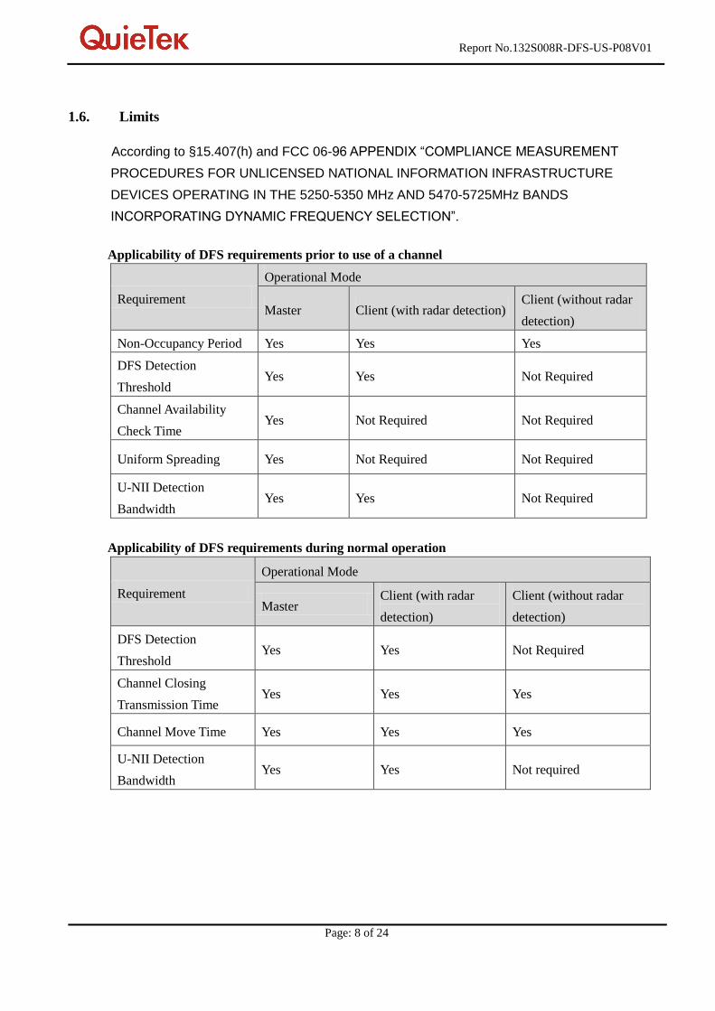
1.6. Limits
According to §15.407(h) and FCC 06-96 APPENDIX “COMPLIANCE MEASUREMENT
PROCEDURES FOR UNLICENSED NATIONAL INFORMATION INFRASTRUCTURE
DEVICES OPERATING IN THE 5250-5350 MHz AND 5470-5725MHz BANDS
INCORPORATING DYNAMIC FREQUENCY SELECTION”.
Applicability of DFS requirements prior to use of a channel
Requirement
Operational Mode
Master Client (with radar detection) Client (without radar
detection)
Non-Occupancy Period Yes Yes Yes
DFS Detection
Threshold Yes Yes Not Required
Channel Availability
Check Time Yes Not Required Not Required
Uniform Spreading Yes Not Required Not Required
U-NII Detection
Bandwidth Yes Yes Not Required
Applicability of DFS requirements during normal operation
Requirement
Operational Mode
Master Client (with radar
detection)
Client (without radar
detection)
DFS Detection
Threshold Yes Yes Not Required
Channel Closing
Transmission Time Yes Yes Yes
Channel Move Time Yes Yes Yes
U-NII Detection
Bandwidth Yes Yes Not required
Report No.132S008R-DFS-US-P08V01
Page: 9 of 24
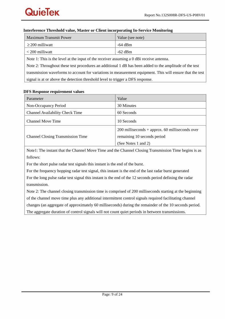
Interference Threshold value, Master or Client incorporating In-Service Monitoring
Maximum Transmit Power Value (see note)
200 milliwatt -64 dBm
< 200 milliwatt -62 dBm
Note 1: This is the level at the input of the receiver assuming a 0 dBi receive antenna.
Note 2: Throughout these test procedures an additional 1 dB has been added to the amplitude of the test
transmission waveforms to account for variations in measurement equipment. This will ensure that the test
signal is at or above the detection threshold level to trigger a DFS response.
DFS Response requirement values
Parameter Value
Non-Occupancy Period 30 Minutes
Channel Availability Check Time 60 Seconds
Channel Move Time 10 Seconds
Channel Closing Transmission Time
200 milliseconds + approx. 60 milliseconds over
remaining 10 seconds period
(See Notes 1 and 2)
Note1: The instant that the Channel Move Time and the Channel Closing Transmission Time begins is as
follows:
For the short pulse radar test signals this instant is the end of the burst.
For the frequency hopping radar test signal, this instant is the end of the last radar burst generated
For the long pulse radar test signal this instant is the end of the 12 seconds period defining the radar
transmission.
Note 2: The channel closing transmission time is comprised of 200 milliseconds starting at the beginning
of the channel move time plus any additional intermittent control signals required facilitating channel
changes (an aggregate of approximately 60 milliseconds) during the remainder of the 10 seconds period.
The aggregate duration of control signals will not count quiet periods in between transmissions.

Report No.132S008R-DFS-US-P08V01
Page: 10 of 24
Short Pulse Radar Test Waveforms
Radar Type Pulse Width
( sec ) PRI ( sec ) Pulses
Minimum
Percentage of
Successful
Detection
Minimum
Trials
1 1 1428 18 60% 30
2 1-5 150-230 23-29 60% 30
3 6-10 200-500 16-18 60% 30
4 11-20 200-500 12-16 60% 30
Aggregate (radar types 1-4) 80% 120
A minimum of 30 unique waveforms is required for each of the short pulse radar type 2 through 4.
For short pulse radar type 1, then same waveform is used a minimum of 30 times. If more than 30
waveforms are used for short pulse radar type 2 through 4, then each additional waveform must also
be unique and not repeated from the previous waveforms. The aggregate is the average of the
percentage of successful detections of short pulse radar type 1-4.
Long Pulse Radar Test Signal
Radar
Waveform Bursts
Pulses Per
Burst
Pulse
Width
( sec )
Chirp
Width
(MHz)
PRI
( sec )
Minimum
Percentage
of
Successful
Detection
Minimum
Trials
5 8-20 1-3 50-100 5-20 1000-2000 80% 30
The parameters for this waveform are randomly chosen. Thirty unique waveforms are required for the long
pulse radar test signal. If more than 30 waveforms are used for the long pulse radar test signal, then each
additional waveform must also be unique and not repeated from the previous waveforms.
Frequency Hopping Radar Test Signal
Radar
Waveform
Pulse
Width
( sec )
PRI
( sec )
Hopping
Sequence
Length
(msec)
Pulses Per
Hop
Hopping
Rate (kHz)
Minimum
Percentage
of
Successful
Detection
Minimum
Trials
6 1 333 300 9 .333 70% 30
For the frequency hopping radar type, the same burst parameters are used for each waveform. The
hopping sequence is different for each waveform and a 100-length segment is selected from the
hopping sequence.
Report No.132S008R-DFS-US-P08V01
Page: 11 of 24
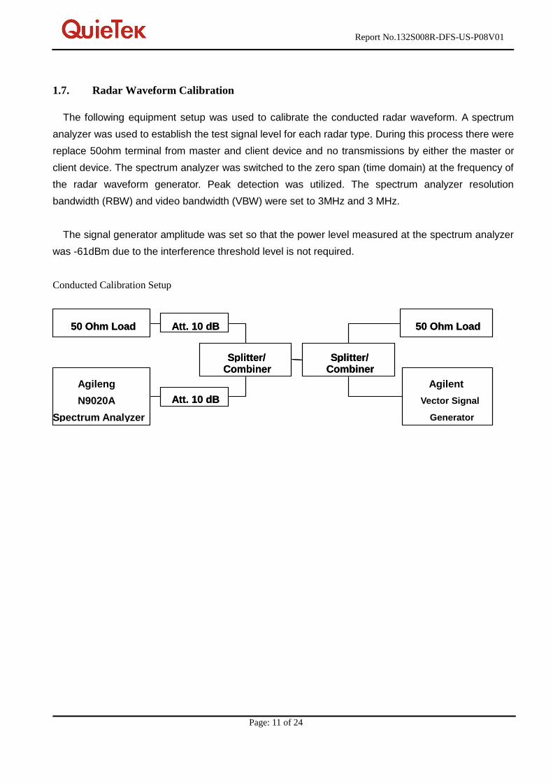
1.7. Radar Waveform Calibration
The following equipment setup was used to calibrate the conducted radar waveform. A spectrum
analyzer was used to establish the test signal level for each radar type. During this process there were
replace 50ohm terminal from master and client device and no transmissions by either the master or
client device. The spectrum analyzer was switched to the zero span (time domain) at the frequency of
the radar waveform generator. Peak detection was utilized. The spectrum analyzer resolution
bandwidth (RBW) and video bandwidth (VBW) were set to 3MHz and 3 MHz.
The signal generator amplitude was set so that the power level measured at the spectrum analyzer
was -61dBm due to the interference threshold level is not required.
Conducted Calibration Setup
50 Ohm Load
Agileng
N9020A
Spectrum Analyzer
Att. 10 dB
Vector Signal
Generator
Splitter/ Combiner
Att. 10 dB
Splitter/ Combiner
50 Ohm Load 50 Ohm Load Att. 10 dB
Agilent
Splitter/ Combiner
Att. 10 dB
Splitter/ Combiner
50 Ohm Load

Report No.132S008R-DFS-US-P08V01
Page: 12 of 24
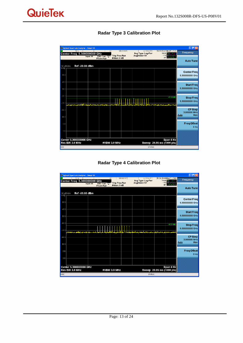
1.8. Radar Waveform Calibration Result
Radar Type 1 Calibration Plot
Radar Type 2 Calibration Plot
Report No.132S008R-DFS-US-P08V01
Page: 13 of 24
Radar Type 3 Calibration Plot
Radar Type 4 Calibration Plot

Report No.132S008R-DFS-US-P08V01
Page: 14 of 24
Radar Type 5 Calibration Plot
Radar Type 6 Calibration Plot

Report No.132S008R-DFS-US-P08V01
Page: 15 of 24
2. Channel Move Time and Channel Closing Transmission Time
2.1. Test Procedure
These tests define how the following DFS parameters are verified during In-Service
Monitoring; Channel Closing Transmission Time and Channel Move Time.
The steps below define the procedure to determine the above mentioned parameters when a
radar burst with a level -61dBm is generated on the operating channel of the U-NII device.
A U-NII device operating as a Client device will associate with the Master device at
5500MHz.
During the in-service monitoring detection probability and channel moving tests the system
was configured with a streaming video file from the master device (sourced by the PC
connected to the master device via an Ethernet interface) to the client device. The streamed
file was the “FCC” test file and the client device was using Media Player Classic as required
by FCC Part 15 Subpart E.
Observe the transmissions of the EUT at the end of the radar burst on the operating
channel for duration greater than 10 seconds. Measure and record the transmissions from the
spectrum analyzer during the observation time (Channel Move Time). Compare the channel
move time and channel closing transmission time results to the limits defined in the DFS
Response requirement values table.
2.2. Test Requirement
Parameter Value
Channel Move Time 10 Seconds
Channel Closing Transmission Time 200 milliseconds + approx. 60 milliseconds over
remaining 10 seconds period
2.3. Uncertainty
± 1ms.

Report No.132S008R-DFS-US-P08V01
Page: 16 of 24
2.4. Test Result of Channel Move Time and Channel Closing Transmission Time
Product : WIRELESS-ABGN 3X3 NETWORK MINI PCIE ADAPTER
Type 1 radar at 5300MHz
Test Item Limit Results
Channel Move Time 10 s Pass
Channel Closing Transmission Time 200ms + an aggregate of 60ms over
remaining 10 second period. Pass

Report No.132S008R-DFS-US-P08V01
Page: 17 of 24
Type 1 radar at 5310MHz
Test Item Limit Results
Channel Move Time 10 s Pass
Channel Closing Transmission Time 200ms + an aggregate of 60ms over
remaining 10 second period. Pass
Report No.132S008R-DFS-US-P08V01
Page: 18 of 24
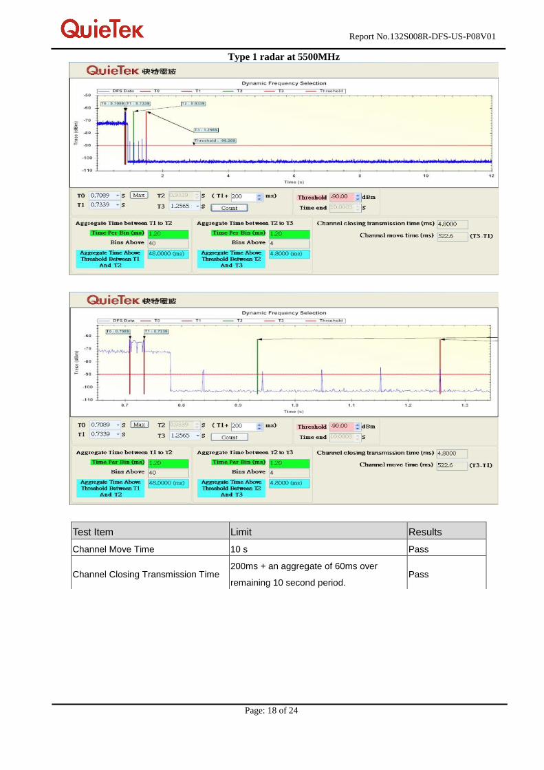
Type 1 radar at 5500MHz
Test Item Limit Results
Channel Move Time 10 s Pass
Channel Closing Transmission Time 200ms + an aggregate of 60ms over
remaining 10 second period. Pass
Report No.132S008R-DFS-US-P08V01
Page: 19 of 24
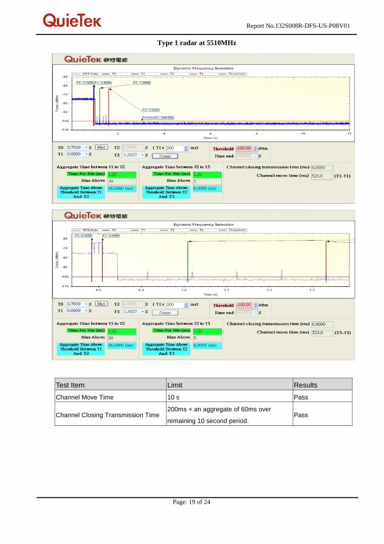
Type 1 radar at 5510MHz
Test Item Limit Results
Channel Move Time 10 s Pass
Channel Closing Transmission Time 200ms + an aggregate of 60ms over
remaining 10 second period. Pass

Report No.132S008R-DFS-US-P08V01
Page: 20 of 24
3. Non-Occupancy Period
3.1. Test Procedur
Measure the EUT for more than 30 minutes following the channel close/move time to verify that the
UUT does not resume any transmissions on this channel.
3.2. Test Requirement
Parameter Value
Non-Occupancy Period 30 Minutes
3.3. Uncertainty
± 1ms.

Report No.132S008R-DFS-US-P08V01
Page: 21 of 24
3.4. Test Result of Non-Occupancy Period
Product : WIRELESS-ABGN 3X3 NETWORK MINI PCIE ADAPTER
Radar Type : Type 1
30 Minute Non-Occupancy Period at 5300 MHz
Test Item Limit Results
Non-Occupancy Period 30 Minutes Pass
No EUT transmissions were observed on the test channel during 30 minutes observation time.

Report No.132S008R-DFS-US-P08V01
Page: 22 of 24
30 Minute Non-Occupancy Period at 5310 MHz
Test Item Limit Results
Non-Occupancy Period 30 Minutes Pass
No EUT transmissions were observed on the test channel during 30 minutes observation time.

Report No.132S008R-DFS-US-P08V01
Page: 23 of 24
30 Minute Non-Occupancy Period at 5500 MHz
Test Item Limit Results
Non-Occupancy Period 30 Minutes Pass
No EUT transmissions were observed on the test channel during 30 minutes observation time.

Report No.132S008R-DFS-US-P08V01
Page: 24 of 24
30 Minute Non-Occupancy Period at 5510 MHz
Test Item Limit Results
Non-Occupancy Period 30 Minutes Pass
No EUT transmissions were observed on the test channel during 30 minutes observation time.
The End