dynamic link library (dll ) communication reference guidedownload.lenze.com/td/p94dll01a__position...
TRANSCRIPT
Dynamic Link Library (DLL )Communication Reference Guide
P94DLL01A
� P94DLL01A
Copyright ©�007 by AC Technology Corporation.
All rights reserved. No part of this manual may be reproduced or transmitted in any form without written permission from AC Technology Corporation. The information and technical data in this manual are subject to change without notice. AC Tech makes no warranty of any kind with respect to this material, including, but not limited to, the implied warranties of its merchantability and fitness for a given purpose. AC Tech assumes no responsibility for any errors that may appear in this manual and makes no commitment to update or to keep current the information in this manual.
MotionView®, PositionServo®, and all related indicia are either registered trademarks or trademarks of Lenze AG in the United States and other countries.
Microsoft Windows®, Visual Basic®, Visual C++® and all related indicia are registered trademarks of the Microsoft Corporation in the United States and other countries.
This document printed in the United States of America
About These InstructionsThis documentation applies to the implementation of DLL with the PositionServo drive and should be used in conjunction with the PositionServo User Manual (S94P01) that shipped with the drive. These documents should be read carefully as they contain important technical data and describe the installation and opera-tion of the drive. This manual describes the use of DLL with the PositionServo drives. It contains informa-tion for anyone who participates in the evaluation of or design of a distributed motion control system. The user should have prior knowledge of motion control, networks and software development.

�P94DLL01A
Table of Contents
1. Safety Information ............................................................................ 41.1 Warnings, Cautions & Notes ...................................................................4
1.� Reference Documents .........................................................................5
�. PositionServo DLL Overview ............................................................. 6
� Files in the DLL Library ..................................................................... 6
4 Communication Flowchart ................................................................ 7
5 DLL Functions Overview ................................................................... 8
6 Return Codes ............................................................................. 8
7 DLL Functions Usage Examples ........................................................ 8
8 DLL Functions ............................................................................. 98.1 Connection Services Functions ...............................................................9
8.� Data Manipulation Functions ................................................................10

4 P94DLL01A
1. Safety Information
1.1 Warnings, Cautions & NotesGeneral
Some parts of Lenze controllers (frequency inverters, servo inverters, DC controllers) can be live, with the potential to cause attached motors to move or rotate. Some surfaces can be hot.
Non-authorized removal of the required cover, inappropriate use, and incorrect installation or operation creates the risk of severe injury to personnel or damage to equipment.
All operations concerning transport, installation, and commissioning as well as maintenance must be car-ried out by qualified, skilled personnel (IEC �64 and CENELEC HD �84 or DIN VDE 0100 and IEC report 664 or DIN VDE0110 and national regulations for the prevention of accidents must be observed).
According to this basic safety information, qualified skilled personnel are persons who are familiar with the installation, assembly, commissioning, and operation of the product and who have the qualifications necessary for their occupation.
Application as directed
Drive controllers are components which are designed for installation in electrical systems or machinery. They are not to be used as appliances. They are intended exclusively for professional and commercial purposes according to EN 61000-�-�. The documentation includes information on compliance with the EN 61000-�-�.
When installing the drive controllers in machines, commissioning (i.e. the starting of operation as directed) is prohibited until it is proven that the machine complies with the regulations of the EC Directive 98/�7/EC (Machinery Directive); EN 60�04 must be observed.
Commissioning (i.e. starting of operation as directed) is only allowed when there is compliance with the EMC Directive (89/��6/EEC).
The drive controllers meet the requirements of the Low Voltage Directive 7�/��/EEC. The harmonised standards of the series EN 50178/DIN VDE 0160 apply to the controllers.
The availability of controllers is restricted according to EN 61800-3. These products can cause radio interference in residential areas.
Installation
Ensure proper handling and avoid excessive mechanical stress. Do not bend any components and do not change any insulation distances during transport or handling. Do not touch any electronic components and contacts.
Controllers contain electrostatically sensitive components, which can easily be damaged by inappropriate handling. Do not damage or destroy any electrical components since this might endanger your health!
Electrical connection
When working on live drive controllers, applicable national regulations for the prevention of accidents (e.g. VBG 4) must be observed.
The electrical installation must be carried out according to the appropriate regulations (e.g. cable cross-sections, fuses, PE connection). Additional information can be obtained from the national regulation docu-mentation. In the United States, electrical installation is regulated by the National Electric Code (nec) and NFPA 70 along with state and local regulations.
5P94DLL01A
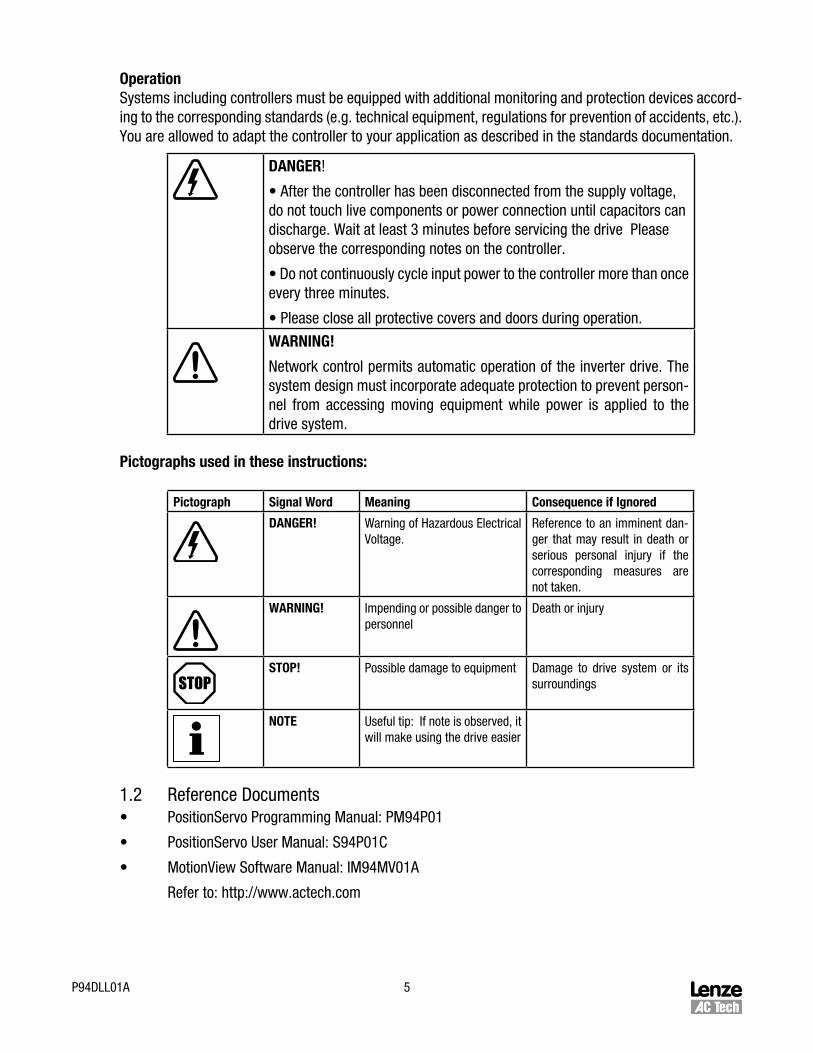
OperationSystems including controllers must be equipped with additional monitoring and protection devices accord-ing to the corresponding standards (e.g. technical equipment, regulations for prevention of accidents, etc.). You are allowed to adapt the controller to your application as described in the standards documentation.
DANGER!
• After the controller has been disconnected from the supply voltage, do not touch live components or power connection until capacitors can discharge. Wait at least � minutes before servicing the drive Please observe the corresponding notes on the controller.
• Do not continuously cycle input power to the controller more than once every three minutes.
• Please close all protective covers and doors during operation.
WARNING!
Network control permits automatic operation of the inverter drive. The system design must incorporate adequate protection to prevent person-nel from accessing moving equipment while power is applied to the drive system.
Pictographs used in these instructions:
Pictograph Signal Word Meaning Consequence if Ignored
DANGER! Warning of Hazardous Electrical Voltage.
Reference to an imminent dan-ger that may result in death or serious personal injury if the corresponding measures are not taken.
WARNING! Impending or possible danger to personnel
Death or injury
STOP! Possible damage to equipment Damage to drive system or its surroundings
NOTE Useful tip: If note is observed, it will make using the drive easier
1.� Reference Documents• PositionServo Programming Manual: PM94P01
• PositionServo User Manual: S94P01C
• MotionView Software Manual: IM94MV01A
Refer to: http://www.actech.com
6 P94DLL01A
�. PositionServo DLL OverviewThis reference guide assumes that the reader has a working knowledge of DLL protocol and familiarity with the programming and operation of motion control equipment. This guide is intended as a reference only.
PositionServo Communication Dynamic-link Library (DLL) provides a set of functions to control, configure and monitor PositionServo drives over Ethernet, RS-485 or RS-��� interfaces. PositionServo drives sup-port the Remote Procedure Call (RPC) protocol to transmit data to and from a master communication unit (PC or controller) and a client-server communication model can be effectively implemented.
All technical details about open standard ONC RPC protocols can be found in RFC-18�1 and RFC-18�� documents. PositionServo uses UDP transport (UDP/IP) to send or receive data over network. In case of serial communications RS��� or RS485, the IP data packets are additionally encapsulated by PPP frame and can be transmitted over the serial interfaces. All encapsulation and data preparation are done by the PositionServo Communication Dynamic-link Library (DLL). See the communication flowchart in Section 4 for detailed steps when writing communication software.
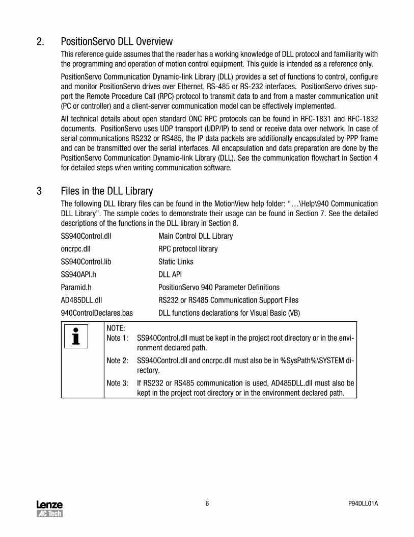
� Files in the DLL LibraryThe following DLL library files can be found in the MotionView help folder: “…\Help\940 Communication DLL Library”. The sample codes to demonstrate their usage can be found in Section 7. See the detailed descriptions of the functions in the DLL library in Section 8.
SS940Control.dll Main Control DLL Library
oncrpc.dll RPC protocol library
SS940Control.lib Static Links
SS940API.h DLL API
Paramid.h PositionServo 940 Parameter Definitions
AD485DLL.dll RS��� or RS485 Communication Support Files
940ControlDeclares.bas DLL functions declarations for Visual Basic (VB)
NOTE:Note 1: SS940Control.dll must be kept in the project root directory or in the envi-
ronment declared path.
Note �: SS940Control.dll and oncrpc.dll must also be in %SysPath%\SYSTEM di-rectory.
Note �: If RS��� or RS485 communication is used, AD485DLL.dll must also be kept in the project root directory or in the environment declared path.
7P94DLL01A
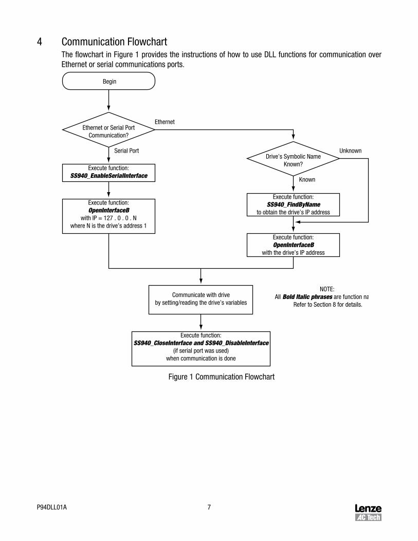
4 Communication FlowchartThe flowchart in Figure 1 provides the instructions of how to use DLL functions for communication over Ethernet or serial communications ports.
Begin
Ethernet or Serial PortCommunication?
Ethernet
Known
Serial PortDrive’s Symbolic Name
Known?
Unknown
Execute function:SS940_EnableSerialInterface
Execute function:SS940_FindByName
to obtain the drive’s IP address
Execute function:OpenInterfaceB
with IP = 127 . 0 . 0 . Nwhere N is the drive’s address 1
Execute function:OpenInterfaceB
with the drive’s IP address
Communicate with driveby setting/reading the drive’s variables
Execute function:SS940_CloseInterface and SS940_DisableInterface
(if serial port was used)when communication is done
NOTE: All Bold Italic phrases are function names.
Refer to Section 8 for details.
Figure 1 Communication Flowchart
8 P94DLL01A
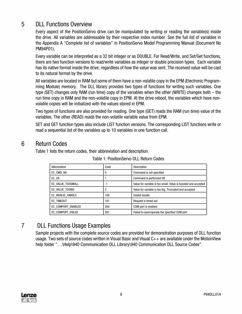
5 DLL Functions OverviewEvery aspect of the PositionServo drive can be manipulated by writing or reading the variable(s) inside the drive. All variables are addressable by their respective index number. See the full list of variables in the Appendix A “Complete list of variables” in PositionServo Model Programming Manual (Document No PM94P01).
Every variable can be interpreted as a �� bit integer or as DOUBLE. For Read/Write, and Set/Get functions, there are two function versions to read/write variables as integer or double precision types. Each variable has its native format inside the drive, regardless of how the value was sent. The received value will be cast to its natural format by the drive.
All variables are located in RAM but some of them have a non-volatile copy in the EPM (Electronic Program-ming Module) memory. The DLL library provides two types of functions for writing such variables. One type (SET) changes only RAM (run time) copy of the variables when the other (WRITE) changes both – the run time copy in RAM and the non-volatile copy in EPM. At the drive reboot, the variables which have non-volatile copies will be initialized with the values stored in EPM.
Two types of functions are also provided for reading. One type (GET) reads the RAM (run time) value of the variables. The other (READ) reads the non-volatile variable value from EPM.
SET and GET function types also include LIST function versions. The corresponding LIST functions write or read a sequential list of the variables up to 10 variables in one function call.
6 Return CodesTable 1 lists the return codes, their abbreviation and description.
Table 1: PositionServo DLL Return Codes
Abbreviation Code Description
EC_CMD_NS 0 Command is not specified
EC_OK 1 Command is performed OK
EC_VALUE_TOOSMALL -1 Value for variable is too small. Value is boosted and accepted
EC_VALUE_TOOBIG � Value for variable is too big. Truncated and accepted
EC_INVALID_HANDLE 100 Invalid handle
EC_TIMEOUT 101 Request is timed out
EC_COMPORT_ENABLED �00 COM port is enabled
EC_COMPORT_FAILED �01 Failed to open/operate the specified COM port
7 DLL Functions Usage ExamplesSample projects with the complete source codes are provided for demonstration purposes of DLL function usage. Two sets of source codes written in Visual Basic and Visual C++ are available under the MotionView help folder “…\Help\940 Communication DLL Library\940 Communication DLL Source Codes”.
9P94DLL01A
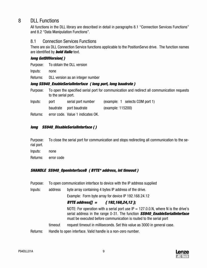
8 DLL FunctionsAll functions in the DLL library are described in detail in paragraphs 8.1 “Connection Services Functions” and 8.� “Data Manipulation Functions”.
8.1 Connection Services FunctionsThere are six DLL Connection Service functions applicable to the PositionServo drive. The function names are identified by bold italic text.
long GetDllVersion( )
Purpose: To obtain the DLL version
Inputs: none
Returns: DLL version as an integer number
long SS940_EnableSerialInterface ( long port, long baudrate )
Purpose: To open the specified serial port for communication and redirect all communication requests to the serial port.
Inputs: port serial port number (example: 1 selects COM port 1)
baudrate port baudrate (example: 115�00)
Returns: error code. Value 1 indicates OK.
long SS940_DisableSerialInterface ( )
Purpose: To close the serial port for communication and stops redirecting all communication to the se-rial port.
Inputs: none
Returns: error code
SHANDLE SS940_OpenInterfaceB ( BYTE* address, int timeout )
Purpose: To open communication interface to device with the IP address supplied
Inputs: address byte array containing 4 bytes IP address of the drive.
Example: Form byte array for device IP 19�.168.�4.1�
BYTE address[] = { 192,168,24,12 };
NOTE: For operation with a serial port use IP = 1�7.0.0.N, where N is the drive’s serial address in the range 0-�1. The function SS940_EnableSerialInterface must be executed before communication is routed to the serial port
timeout request timeout in milliseconds. Set this value as �000 in general case.
Returns: Handle to open interface. Valid handle is a non-zero number.

10 P94DLL01A
long SS940_CloseInterface ( SHANDLE handle )
Purpose: To close the communication interface to device with the specific handle.
Inputs: handle to the previously opened interface by the function SS940_OpenInterfaceB.
Return: error code
long SS940_FindByName ( char* name, BYTE* ip_address, BYTE* ser_num, int timeout )
Purpose: To find PositionServo drives on the network by their names and retrieve their IP addresses and serial address numbers.
Inputs: name ASCII string containing the drive’s name
Timeout request time out in ms. Set it in �000 ms for general use
Return: ip_address 4 bytes drive’s IP address.
ser_num 4 bytes serial number information
8.� Data Manipulation FunctionsThere are twelve DLL Data Manipulation Functions that apply to the PositionServo drive.
long SS940_ReadParamAsDouble ( SHANDLE h, int pid, double& param )
Purpose: To read the EPM copy of the variable as a DOUBLE type with the index specified by pid and return it in argument parameter.
Inputs: h handle to interface opened by SS940_OpenInterfaceB
pid variable (parameter) index
Returns: param variable value in double format
long SS940_ReadParamAsInteger ( SHANDLE h, int pid, int& param )
Purpose: To read EPM copy of the variable as a ��-bit INTEGER type with index specified by pid and return it in argument parameter.
Inputs: h handle to interface opened by SS940_OpenInterfaceB
pid variable (parameter) index
Returns: param variable value in integer format

11P94DLL01A
long SS940_GetParamAsDouble ( SHANDLE h, int pid, double& param )
Purpose: To read a RAM (run time) variable as a DOUBLE type with index specified by pid and return it in argument parameter.
Inputs: h handle to interface opened by the function SS940_OpenInterfaceB
pid variable (parameter) index
Returns: param variable value in double format
long SS940_GetParamAsInteger ( SHANDLE h, int pid, int& param )
Purpose: To read the RAM (run time) variable as a ��-bit INTEGER type with index specified by pid and return it in argument parameter.
Inputs: h handle to interface opened by the function SS940_OpenInterfaceB
pid variable (parameter) index
Returns: param variable value in integer format
long SS940_WriteParamAsDouble ( SHANDLE h, int pid, double param )
Purpose: To write the RAM (run time) and EPM copies of the variable as a DOUBLE type with index speci-fied by pid and return it in argument parameter.
Inputs: h handle to interface opened by the function SS940_OpenInterfaceB
pid variable (parameter) index
Returns: param variable value in double format
long SS940_WriteParamAsInteger ( SHANDLE h, int pid, int param )
Purpose: To write the RAM (run time) and EPM copies of the variable as a DOUBLE type with index speci-fied by pid and return it in argument parameter.
Inputs: h handle to interface opened by the function SS940_OpenInterfaceB
pid variable (parameter) index
Returns: param variable value in integer format
1� P94DLL01A
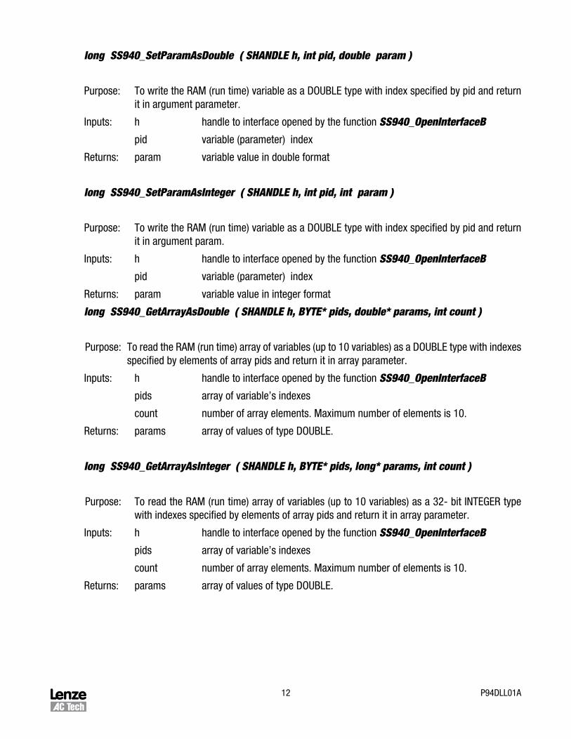
long SS940_SetParamAsDouble ( SHANDLE h, int pid, double param )
Purpose: To write the RAM (run time) variable as a DOUBLE type with index specified by pid and return it in argument parameter.
Inputs: h handle to interface opened by the function SS940_OpenInterfaceB
pid variable (parameter) index
Returns: param variable value in double format
long SS940_SetParamAsInteger ( SHANDLE h, int pid, int param )
Purpose: To write the RAM (run time) variable as a DOUBLE type with index specified by pid and return it in argument param.
Inputs: h handle to interface opened by the function SS940_OpenInterfaceB
pid variable (parameter) index
Returns: param variable value in integer format
long SS940_GetArrayAsDouble ( SHANDLE h, BYTE* pids, double* params, int count )
Purpose: To read the RAM (run time) array of variables (up to 10 variables) as a DOUBLE type with indexes specified by elements of array pids and return it in array parameter.
Inputs: h handle to interface opened by the function SS940_OpenInterfaceB
pids array of variable’s indexes
count number of array elements. Maximum number of elements is 10.
Returns: params array of values of type DOUBLE.
long SS940_GetArrayAsInteger ( SHANDLE h, BYTE* pids, long* params, int count )
Purpose: To read the RAM (run time) array of variables (up to 10 variables) as a ��- bit INTEGER type with indexes specified by elements of array pids and return it in array parameter.
Inputs: h handle to interface opened by the function SS940_OpenInterfaceB
pids array of variable’s indexes
count number of array elements. Maximum number of elements is 10.
Returns: params array of values of type DOUBLE.
1�P94DLL01A
long SS940_SetArrayAsDouble ( SHANDLE h, long* pids, double* params, int count )
Purpose: To write the RAM (run time) array of variables (up to 10 variables) as a DOUBLE type with in-dexes specified by elements of array pids and return it in array parameter.
Inputs: h handle to interface opened by the function SS940_OpenInterfaceB
pids array of variable’s indexes
count number of array elements. Maximum number of elements is 10.
Returns: params array of error codes
long SS940_SetArrayAsInteger ( SHANDLE h, long* pids ,longt* params, int count )
Purpose: To write the RAM (run time) array of variables (up to 10 variables) as a type �� bit INTEGER type with indexes specified by elements of array pids and return it in array parameter.
Inputs: h handle to interface opened by the function SS940_OpenInterfaceB
pids array of variable’s indexes
count number of array elements. Maximum number of elements is 10.
Returns: params array of error codes

AC Technology Corporationwww.actech.com6�0 Douglas StreetUxbridge, MA 01569Telephone: (508) �78-9100Facsimile: (508) �78-787�
P94DLL01A