dynamic model of an oilwell drillstring with stick-slip ... · pdf filedynamic model of an...
TRANSCRIPT
Dynamic Model of an Oilwell Drillstring with Stick-Slip and Bit-Bounce Interaction
Md. Mejbahul Sarker, Graduate Student
D. Geoff Rideout, Associate Professor
Stephen D. Butt, Professor
Faculty of Engineering and Applied Science
Memorial University of Newfoundland
E-mail: [email protected], [email protected], [email protected]
Keywords: Drilling, vibration, lumped-segment model,
stick-slip, bit-bounce, optimal control, bit-rock interaction.
Abstract
Oilwell drillstrings sometimes vibrate severely and
can twist off in hard rock drilling. Stick-slip particularly
predominates when drilling with polycrystalline diamond
compact (PDC) bits, which may also excite severe axial and
lateral vibrations in the bottom hole assembly, causing
damage to the drillstrings and downhole equipment.
Controlling these vibrations is essential to improving the
efficiency and minimizing the cost of drilling. A bond graph
model of a drillstring has been developed that predicts axial
vibration, torsional vibration, and coupling between axial
and torsional vibration due to bit-rock interaction. Axial and
torsional submodels use a lumped-segment approach, with
each submodel having a total of 21 segments to capture
vibration of the kelly, drill pipes, and drill collars. In
addition, the model incorporates viscous damping,
hydrodynamic damping, and hydraulic forces due to drilling
mud; an empirical treatment of rock-bit interaction, and top
drive motor dynamics. The model predicts the expected
coupling between weight on bit (WOB), bit speed, and rock-
bit interface conditions; and their effect on stick-slip. Low
bit speed and high WOB cause stick-slip. Mitigating open-
loop measures used in the drilling industry (increasing
rotary speed and decreasing WOB through changing derrick
cable tension) were applied to the model, and successfully
eliminated stick-slip. A linear quadratic regulator (LQR)
controller was then implemented which controlled stick slip
and eliminated bit bounce.
1 Introduction
Deep wells for the exploration and production of
oil and gas are drilled with a rock-cutting tool driven from
the surface by a slender structure of pipes, called the
drillstring (Fig. 1). Drillstring vibration is one of the major
causes of deterioration of drilling performance in deep well
applications. Bit-formation interaction has been recognized
as a major cause of drillstring vibration. Bit induced
vibration occurs in various forms namely whirl, stick-slip,
and bit-bounce. However, stick-slip predominates when
drilling with drag bits (especially with PDC bits) and stick-
slip oscillations induce large cyclic stresses, which can lead
to fatigue problems, reduction of bit life, unexpected
changes in drilling direction, and even failure of the
drillstring. Stick-slip vibration has received considerable
attention in recent years with increasing use of PDC bits in
harder formations, and has motivated extensive research on
this type of drillstring vibration.
Several dynamic formulations have been reported
for investigating specific aspects of drillstring vibrational
behavior and few of them have tackled stick-slip. One of the
major difficulties in modeling stick-slip stems from the
inaccurate description of some involved parameters and
downhole boundary conditions. Leine et al. [1]
presented a stick-slip whirl model which consists of a
submodel for the whirling motion and a submodel for the
stick-slip motion. The stick-slip whirl model was a
simplification of drilling confined in a borehole with drilling
mud. Their model was a low-dimensional model and it
aimed at explaining the basic nonlinear dynamic phenomena
observed in downhole experiments. The model system was
analyzed with the discontinuous bifurcations method which
indicates physical phenomena such as dry friction, impact
and backlash in mechanical systems or diode elements in
electrical circuits which are often studied by means of
mathematical models with some kind of discontinuity. The
disappearance of stick-slip vibration when whirl vibration
appears was explained by bifurcation theory. Stick slip was
prevalent at low angular velocity and backward whirl was
prevalent for high angular velocity consistent with the
measurements. They did not consider the effect of axial
vibration and rock-bit interaction in the model.
Christoforou and Yigit [2,3] used a simple dynamic
model to simulate the effects of varying operating
conditions on stick-slip and bit bounce interactions. The
equations of motion of such a system were developed by
using a simplified lumped parameter model with only one
compliance. This model did not account for the effect of
Proc. International Conference on Bond Graph Modeling ICBGMS'12, July 8-11, Genoa, Italy
higher modes, the flow inside and outside the drillpipe and
collars, or complicated cutting and friction conditions at the
bit/formation interface.
Richard et al. [4,5] studied the self-excited stick-
slip oscillations of a rotary drilling system with a drag bit,
using a discrete model which takes into consideration the
axial and torsional vibration modes of the bit. Coupling
between these two vibration modes took place through a bit-
rock interaction law which accounted for both frictional
contact and cutting processes at the bit-rock interface. The
cutting process introduced a delay in the equations of
motion which was ultimately responsible for the existence
of self-excited vibrations, exhibiting stick-slip oscillations
under certain conditions. One of the limitations of their
model is that the simulation stops when the bit lifts off.
Furthermore, their model reduced the drillstring to a two
degree of freedom system and they were working to capture
more modes of vibration.
Recently Khulief et al. [6] formulated a finite
element dynamic model of the drillstring including the drill
pipes and drill collars. The model accounted for the
torsional-bending inertia coupling and the axial-bending
geometric nonlinear coupling. In addition the model
accounted for the gyroscopic effect, the effect of the
gravitational force field, and stick-slip interaction forces.
Complex modal transformations were applied and reduced-
order models were obtained. The finite element formulation
was then integrated into a computational scheme for
calculating the natural frequencies of the whole drillstring.
The computational scheme was extended further to integrate
the equations of motion, either in the full-order or the
reduced-order form, to obtain the dynamic response.
MATLABTM
was used as a simulation tool. They did not
consider hydrodynamic damping, due to drilling fluid
circulation in the drill pipe and the annular space, in their
model. Stick-slip interaction was giving a coupling between
axial and torsional vibration but [6] did not have any
discussion about the complex effect of bit rotary speed and
threshold force on torque on bit.
This paper presents a bond graph model of the
whole drillstring including both drill pipes and drill collars.
In addition to the axial vibration, torsional vibration, and
axial-torsional coupling due to rock-bit interaction, the
developed model accounts for the self weight effect, the
associated tension and compression fields, viscous damping,
hydrodynamic damping, and hydraulic forces due to drilling
mud within the drillstring; an empirical treatment of rock-bit
interaction, and top drive motor dynamics. The main
contribution of this work is a model suitable for parametric
study of the effect of table rotary speed and weight on bit on
stick-slip vibration, and the coupling between stick-slip and
bit bounce. Active control of the rotary table to suppress
stick-slip and bit bounce is also implemented.
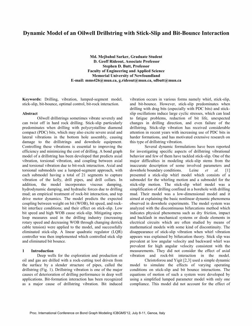
2 Modeling of Oilwell Drilling System
The system being modeled consists of drill pipes,
the drill collar assembly (made up of heavier collar pipes),
the drill bit at the end of the collar assembly and the rock
(formation). Drilling fluid is circulated in the drill pipe and
the annular space between the drill pipe and the well bore.
The drilling fluid is characterized by the flow rate developed
by the mud pumps. The top of the drillstring is subject to a
tension force, applied through the surface cables. Rotary
motion is applied by an armature-controlled motor, through
a gearbox, to the rotary table via the kelly (a square,
hexagonal or octagonal shaped tubing that is inserted
through and is an integral part of the rotary table that moves
freely vertically while the rotary table turns it). In this study,
a DC motor with winding inductance and resistance is
assumed. The essential components of the oilwell drilling
system and the necessary geometry used for the model are
shown in Fig. 1. A lumped-segment approach is used in the
axial and torsional dynamic models. In the lumped segment
approach, the system is divided into a number of elements,
interconnected with springs. This method is a more
cumbersome bond graph representation and the accuracy of
the model depends on the number of elements considered;
however, analytic mode shapes and natural frequencies need
not be determined.
Fig. 1 Oilwell drilling system (adapted from [1])
Proc. International Conference on Bond Graph Modeling ICBGMS'12, July 8-11, Genoa, Italy
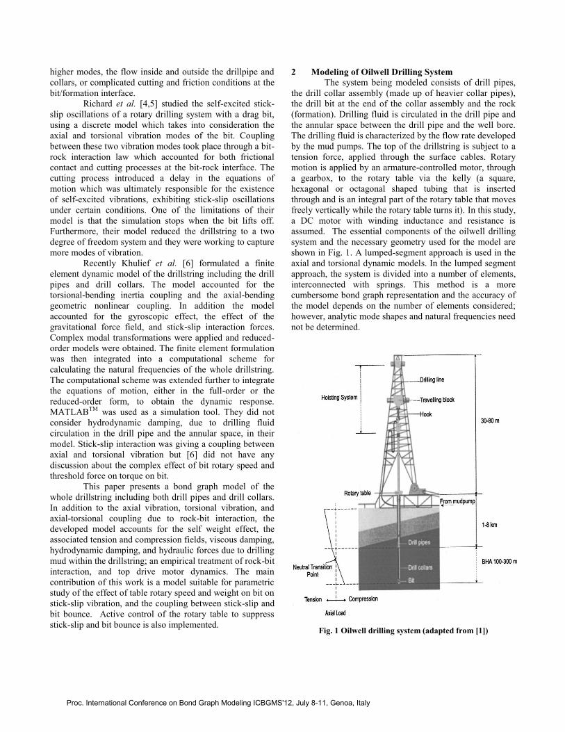
2.1 Modeling of Axial Dynamics
A total of 21 segments are used in the dynamic
model to capture the first eight axial natural frequencies of
the whole drillstring. One segment is used for the relatively
short kelly, and the kelly model is shown in Fig. 2. For both
drill pipe and collar, 10 segments are used in the model, and
a drill pipe/collar bond graph model segment is shown in
Fig. 3. Hydraulic forces are included at the top of the drill
collar and bottom of the drillstring to capture the effect of
drilling mud density. Hydrodynamic damping, due to
drilling fluid circulation in the drill pipe and the annular
space, is considered in the drill pipe and collar model
instead of viscous damping [8].
Fig. 2 Bond graph axial model segment of Kelly
Fig. 3 Bond graph axial model segment of drill pipe/collar
2.2 Modeling of Torsional Dynamics
Similarly a total of 21 segments are used in the
dynamic model to capture the first eight torsional natural
frequencies of the whole drillstring. The number of
segments for the kelly, drill pipe and drill collar is the same
as in the torsional model. Fig. 4 and 5 depict torsional
dynamic submodels for kelly and drill pipe/collar segments.
The drill pipe and drill collar dynamic models consider
viscous damping which results from the contact between
drillstring surfaces and drilling fluid [8].
Fig. 4 Bond graph torsional model segment of kelly
Fig. 5 Bond graph torsional model segment of drill pipe/collar
2.3 Coupling Between Axial and Torsional Dynamics
The bit-rock interaction provides coupling between
axial and torsional drillstring dynamics. In this present work
a quasi-static rock-bit model is used instead of a
computationally intensive and difficult-to-parameterize
complete dynamic representation. Yigit and Christoforou
[2,3] have shown a static rock-bit interaction model in a
drillstring represented using only two inertias and one
compliance for both axial and torsional vibration. Their
model is modified as described below. The original model
in [3] assumed both friction and cutting torque regardless of
whether or not dynamic weight on bit was sufficient to
create penetration and cuttings. Depth of cut was a function
of average rather than instantaneous rotation speed, along
with rate of penetration. Rate of penetration was a function
of average rotation speed and a constant applied weight on
bit (WOB), rather than dynamic weight on bit. This paper
incorporates threshold force and the effect of instantaneous
WOB and bit rotation speed on cutting torque on bit (TOB).
Below a threshold force 𝑊𝑓𝑠 , the drill tool does not penetrate
into the rock, leaving only friction as a source of TOB. The
model equations are presented in two parts. First, the
dynamic WOB, which is the axial force applied at the bit
under dynamic conditions is given as in [3]
WOB = kc(x − s) if 𝑥 ≥ s
0 if 𝑥 < 𝑠 (1)
where 𝑘𝑐 and s indicate formation contact stiffness and
bottom-hole surface profile. Surface profile is given as [3]
s = s0 𝑓(∅) (2)
Effective_Weight
Mass
Mat_DampingKelly_Compliance
1
v
Se
I
1
RC
0
F
p_Outputp_Input
Annulus_Mud_Flow
Mud_Flow_In_Pipe
Annulus_Hy draulic_DampingInside_Hy draulic_Damping
Ef f ectiv e_Weight
Compliance Material_Damping
Mass
Displacement
0 0
1
v
1
1
RI
R
Sf
0
F
Se
C
R
Sf
p_Output p_Input
Kelly _Inertia
Compliance Material_Damping
1
w
C
0
T
1
R
I
p_Output p_Input
Fluid_Resistance
Inertia
Material_DampingTorsional_Compliance
1
w
C
0
T
1
R
I
R
p_Output p_Input
Proc. International Conference on Bond Graph Modeling ICBGMS'12, July 8-11, Genoa, Italy
Fig. 6 Bond graph model of rotary drilling system
The formation elevation function 𝑓(∅) is chosen to be
sinusoidal as in [3], 𝑓 ∅ = sin 𝑏∅, where b indicates bit
factor which depends on the bit type. The term ∅ indicates
rotational displacement of the bit.
The total torque on bit (TOB) is related to frictional
and cutting conditions, and dynamic WOB. When bit rotary
speed is in the positive direction then TOB can be written as
TOB = TOB𝑓 + TOB𝐶 𝑊𝑂𝐵 > W𝑓𝑠
TOB𝑓 𝑊𝑂𝐵 ≤ W𝑓𝑠
(3)
In the case of zero bit rotary speed
TOB = TOB𝐶 𝑊𝑂𝐵 > W𝑓𝑠
0 𝑊𝑂𝐵 ≤ W𝑓𝑠
(4)
Finally for negative bit rotary speed
TOB = TOB𝑓 (5)
where TOB𝑓 and TOB𝐶 represent frictional and cutting
torque on bit and both are calculated as below,
TOB𝑓 = WOB 𝑟𝑏𝜇 ∅ (6)
TOB𝐶 = WOB 𝑟𝑏ξ 𝛿𝐶
𝑟𝑏 (7)
The term ∅ indicates instantaneous bit rotary speed, and the
function 𝜇 ∅ characterizes the friction process at the bit
and it is given as [3]
𝜇 ∅ = 𝜇0 tanh ∅ +α∅
1+β∅ 2γ + 𝜈∅ (8)
where 𝜇0, 𝛼, 𝛽, 𝛾, and ν are the experimentally-determined
parameters of the frictional model. In equation (7) the terms
𝑟𝑏and 𝛿𝐶 indicate bit radius and depth of cut per revolution,
the latter given as
𝛿𝐶 =2𝜋ROP
∅ (9)
The instantaneous rate of penetration (ROP) is a function of
dynamic WOB, instantaneous bit speed ∅ , and rock/bit
characteristics. The modified ROP equation from [3] can be
written as
ROP = 𝐶1WOB ∅ + 𝐶2 (10)
where 𝜉, 𝐶1 and 𝐶2 characterize the cutting action at the bit
and depend on the type of the bit and formation.
Rock-Bit Model
Torsional Dynamic ModelAxial Dynamic Model
0
0
0
MSe
TOB
1
Rotary_Table
R
Rotary_damping
C
Rock_C
R
Resistance
Axial
Pipe_axial9
Axial
Pipe_axial8
Axial
Pipe_axial7
Axial
Pipe_axial6
Axial
Pipe_axial5
Axial
Pipe_axial4
Axial
Pipe_axial3
Axial
Pipe_axial2
Axial
Pipe_axial1
Axial
Pipe_axial
1
1
1
1
I
Motor_inductance
GY
Motor_constant
1
Motor
Torsion
Kelly_Table_Motor_Inertia
Axial
Swiv el
Kelly_Swivel
Integrate
Se
Input_Voltage
TF
Gear_Ratio
MSf
Flow_Excitation
Sf
Fixed_support
Se
F2_Hydraulic
Torsion
DrillPipe_Tor9
Torsion
DrillPipe_Tor8
Torsion
DrillPipe_Tor7
Torsion
DrillPipe_Tor6
Torsion
DrillPipe_Tor5
Torsion
DrillPipe_Tor4
Torsion
DrillPipe_Tor3
Torsion
DrillPipe_Tor2
Torsion
DrillPipe_Tor1
Torsion
DrillPipe_Tor
Torsion
DrillCollar_Tor9
Torsion
DrillCollar_Tor8
Torsion
DrillCollar_Tor7
Torsion
DrillCollar_Tor6
Torsion
DrillCollar_Tor5
Torsion
DrillCollar_Tor4
Torsion
DrillCollar_Tor3
Torsion
DrillCollar_Tor2
Torsion
DrillCollar_Tor1
Torsion
DrillCollar_Tor
Cosine
Axial
Collar_axial9
Axial
Collar_axial8
Axial
Collar_axial7
Axial
Collar_axial6
Axial
Collar_axial5
Axial
Collar_axial4
Axial
Collar_axial3
Axial
Collar_axial2
Axial
Collar_axial1
Axial
F1
Collar_axial
C
Cable_derrick_C
R
Cable_Damping
Se
Bit_Weight
1Bit_Rotation
IBit_Mass
I
Bit_Inertia
Proc. International Conference on Bond Graph Modeling ICBGMS'12, July 8-11, Genoa, Italy
3 Simulation Data
The bond graph model of the rotary drilling system
is shown in Fig. 6. Table 1 summarizes all relevant data
that is used in the current simulation.
Table 1 Data used in rotary drilling simulation
Drillstring data Cable and derrick spring constant 9.3e+06 N/m
Swivel and derrick mass 7031 kg
Kelly length 15 m
Kelly outer diameter 0.379 m
Kelly inner diameter 0.0825 m
Drill pipe length 2000 m
Drill pipe outer diameter 0.101 m (4 in)
Drill pipe inner diameter 0.0848 m (3.34 in)
Drill collar length 200 m
Drill collar outer diameter 0.171 m (6.75 in)
Drill collar inner diameter 0.0571 m (2.25 in)
Drill string material Steel
Wellbore diameter 0.2 m
Drill bit-rock data
Bit type PDC (Single cutter)
Drill bit diameter 0.2 m (7.875 in)
Drill bit mass 65 kg
Rock stiffness 1.16e+09 N/m
Rock damping 1.5e+05 N.sec/m
Surface elevation amplitude 𝑠0 0.001
Bit factor, b 1
Cutting coefficient 𝜉, 𝐶1, 𝐶2 1, 1.35e-08, -1.9e-4
Frictional coefficient 𝜇0,𝛼,𝛽,𝛾& 𝜈 0.06, 2, 1, 1 & 0.01
Threshold force, 𝑊𝑓𝑠 10000 N
Hydraulic data
Mud fluid density 1198 kg/m3
Mud flow rate, Q 𝑄𝑚 + 𝑄𝑎 sin(𝑞𝑡)
Mean mud flow rate, 𝑄𝑚 0.022 m3/sec
Mud flow pulsation amplitude, 𝑄𝑎 0.002 m3/sec
Freq. of variation in mud flowrate, q 25.13 rad/sec
Equivalent fluid viscosity for fluid
resistance to rotation 𝜇𝑒
30e-03 Pa.sec
Weisbach friction factor outside drill
pipe or collar, 𝛼𝑎
0.045
Weisbach friction factor inside drill
pipe or collar, 𝛼𝑝
0.035
Motor data
L, 𝐾𝑚 , n and Rm, 0.005 H, 6 V/s, 7.2
and 0.01 Ω
4 Stick-slip and Bit-bounce Interaction
The main objective of the current simulations is to
study stick-slip vibrations and the effect of this vibration on
bit-bounce. During bit-bounce the drill bit alternately
separates from and impacts the rock surface in the
longitudinal direction during drilling. When the bit is off-
bottom the critical frequencies for axial resonances are
found to be 2.3, 8.7, 15.7, 20.9, 25.7, 32.7, 40.0, 47.3
rad/sec…etc.; and for torsional resonances are found to be
1.2, 5.3, 10.1, 14.9, 19.8, 24.4 28.9, 33.3 rad/sec…etc.
When the bit is in contact with rock (on-bottom condition)
the critical frequencies for axial resonance are found to be
7.7, 15.1, 20.5, 25.1, 31.8, 37.9, 42.1, 48.0 rad/sec…etc.. It
was found that for axial vibrations the frequencies 31.8,
37.9 and 42.1 rad/sec gave the greatest increases in dynamic
forces at the bit. When the bit rotary speed reached that
critical frequency range then high dynamic forces at the bit
or bit bounce resulted as in Figs. 7-10.
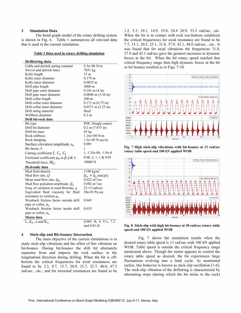
Fig. 7 High stick-slip vibrations with bit-bounce at 13 rad/sec
rotary table speed and 100 kN applied WOB
Fig. 8 Stick-slip with high bit-bounce at 30 rad/sec rotary table
speed and 100 kN applied WOB
Fig. 7 shows the simulation results when the
desired rotary table speed is 13 rad/sec with 100 kN applied
WOB. Table speed is outside the critical frequency range
mentioned above. Though the motor appears to control the
rotary table speed as desired, the bit experiences large
fluctuations evolving into a limit cycle. As mentioned
earlier, this behavior is known as stick-slip oscillation [1-6].
The stick-slip vibration of the drillstring is characterized by
alternating stops (during which the bit sticks to the rock)
Proc. International Conference on Bond Graph Modeling ICBGMS'12, July 8-11, Genoa, Italy
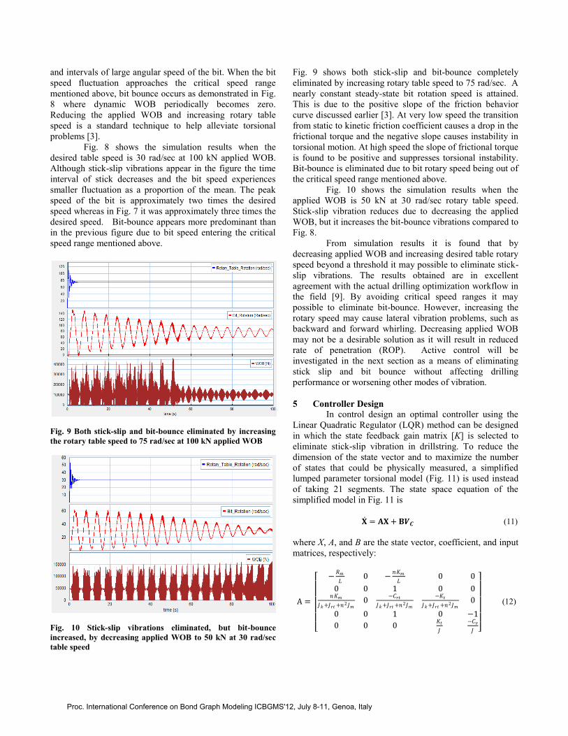
and intervals of large angular speed of the bit. When the bit
speed fluctuation approaches the critical speed range
mentioned above, bit bounce occurs as demonstrated in Fig.
8 where dynamic WOB periodically becomes zero.
Reducing the applied WOB and increasing rotary table
speed is a standard technique to help alleviate torsional
problems [3].
Fig. 8 shows the simulation results when the
desired table speed is 30 rad/sec at 100 kN applied WOB.
Although stick-slip vibrations appear in the figure the time
interval of stick decreases and the bit speed experiences
smaller fluctuation as a proportion of the mean. The peak
speed of the bit is approximately two times the desired
speed whereas in Fig. 7 it was approximately three times the
desired speed. Bit-bounce appears more predominant than
in the previous figure due to bit speed entering the critical
speed range mentioned above.
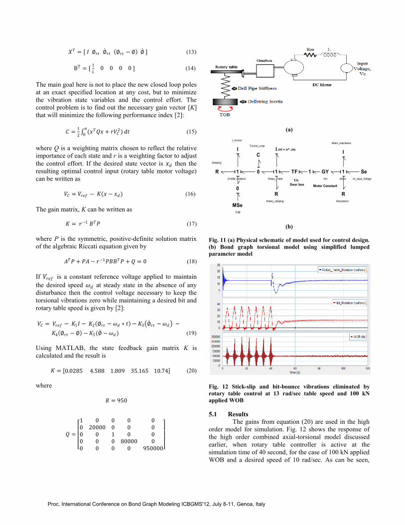
Fig. 9 Both stick-slip and bit-bounce eliminated by increasing
the rotary table speed to 75 rad/sec at 100 kN applied WOB
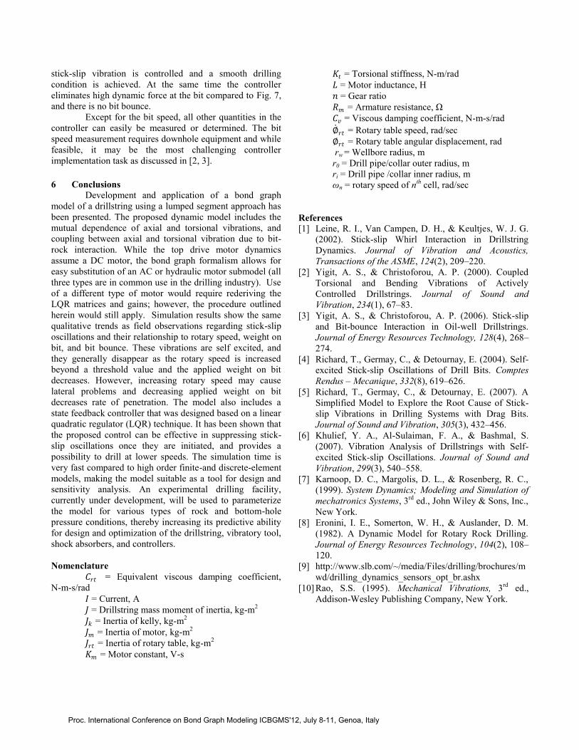
Fig. 10 Stick-slip vibrations eliminated, but bit-bounce
increased, by decreasing applied WOB to 50 kN at 30 rad/sec
table speed
Fig. 9 shows both stick-slip and bit-bounce completely
eliminated by increasing rotary table speed to 75 rad/sec. A
nearly constant steady-state bit rotation speed is attained.
This is due to the positive slope of the friction behavior
curve discussed earlier [3]. At very low speed the transition
from static to kinetic friction coefficient causes a drop in the
frictional torque and the negative slope causes instability in
torsional motion. At high speed the slope of frictional torque
is found to be positive and suppresses torsional instability.
Bit-bounce is eliminated due to bit rotary speed being out of
the critical speed range mentioned above.
Fig. 10 shows the simulation results when the
applied WOB is 50 kN at 30 rad/sec rotary table speed.
Stick-slip vibration reduces due to decreasing the applied
WOB, but it increases the bit-bounce vibrations compared to
Fig. 8.
From simulation results it is found that by
decreasing applied WOB and increasing desired table rotary
speed beyond a threshold it may possible to eliminate stick-
slip vibrations. The results obtained are in excellent
agreement with the actual drilling optimization workflow in
the field [9]. By avoiding critical speed ranges it may
possible to eliminate bit-bounce. However, increasing the
rotary speed may cause lateral vibration problems, such as
backward and forward whirling. Decreasing applied WOB
may not be a desirable solution as it will result in reduced
rate of penetration (ROP). Active control will be
investigated in the next section as a means of eliminating
stick slip and bit bounce without affecting drilling
performance or worsening other modes of vibration.
5 Controller Design
In control design an optimal controller using the
Linear Quadratic Regulator (LQR) method can be designed
in which the state feedback gain matrix [K] is selected to
eliminate stick-slip vibration in drillstring. To reduce the
dimension of the state vector and to maximize the number
of states that could be physically measured, a simplified
lumped parameter torsional model (Fig. 11) is used instead
of taking 21 segments. The state space equation of the
simplified model in Fig. 11 is
𝐗 = 𝐀𝐗 + 𝐁𝑽𝑪 (11)
where X, A, and B are the state vector, coefficient, and input
matrices, respectively:
A =
−
𝑅𝑚
𝐿0 −
𝑛𝐾𝑚
𝐿0 0
0 0 1 0 0𝑛𝐾𝑚
𝐽𝑘 +𝐽𝑟𝑡 +𝑛2𝐽𝑚0
−𝐶𝑟𝑡
𝐽𝑘 +𝐽𝑟𝑡 +𝑛2𝐽𝑚
−𝐾𝑡
𝐽𝑘 +𝐽𝑟𝑡 +𝑛2𝐽𝑚0
0 0 1 0 −1
0 0 0𝐾𝑡
𝐽
−𝐶𝑣
𝐽
(12)
Proc. International Conference on Bond Graph Modeling ICBGMS'12, July 8-11, Genoa, Italy
𝑋𝑇 = [ 𝐼 ∅𝑟𝑡 ∅ 𝑟𝑡 ∅𝑟𝑡 − ∅ ∅ ] (13)
BT = [ 1
𝐿0 0 0 0 ] (14)
The main goal here is not to place the new closed loop poles
at an exact specified location at any cost, but to minimize
the vibration state variables and the control effort. The
control problem is to find out the necessary gain vector [K]
that will minimize the following performance index [2]:
𝐶 =1
2 (𝑥𝑇𝑄𝑥 + 𝑟𝑉𝐶
2)∝
0𝑑𝑡 (15)
where Q is a weighting matrix chosen to reflect the relative
importance of each state and r is a weighting factor to adjust
the control effort. If the desired state vector is 𝑥𝑑 then the
resulting optimal control input (rotary table motor voltage)
can be written as
𝑉𝐶 = 𝑉𝑟𝑒𝑓 − 𝐾(𝑥 − 𝑥𝑑 ) (16)
The gain matrix, K can be written as
𝐾 = 𝑟−1 𝐵𝑇𝑃 (17)
where P is the symmetric, positive-definite solution matrix
of the algebraic Riccati equation given by
𝐴𝑇𝑃 + 𝑃𝐴 − 𝑟−1𝑃𝐵𝐵𝑇𝑃 + 𝑄 = 0 (18)
If 𝑉𝑟𝑒𝑓 is a constant reference voltage applied to maintain
the desired speed 𝜔𝑑 at steady state in the absence of any
disturbance then the control voltage necessary to keep the
torsional vibrations zero while maintaining a desired bit and
rotary table speed is given by [2]:
𝑉𝐶 = 𝑉𝑟𝑒𝑓 − 𝐾1𝐼 − 𝐾2 ∅𝑟𝑡 − 𝜔𝑑 ∗ 𝑡 − 𝐾3 ∅ 𝑟𝑡 − 𝜔𝑑 −
𝐾4 ∅𝑟𝑡 − ∅ − 𝐾5(∅ − 𝜔𝑑 ) (19)
Using MATLAB, the state feedback gain matrix K is
calculated and the result is
𝐾 = [0.0285 4.588 1.809 35.165 10.74] (20)
where
𝑅 = 950
𝑄 =
1 0 0 0 00 20000 0 0 00 0 1 0 00 0 0 80000 00 0 0 0 950000
(a)
(b)
Fig. 11 (a) Physical schematic of model used for control design.
(b) Bond graph torsional model using simplified lumped
parameter model
Fig. 12 Stick-slip and bit-bounce vibrations eliminated by
rotary table control at 13 rad/sec table speed and 100 kN
applied WOB
5.1 Results
The gains from equation (20) are used in the high
order model for simulation. Fig. 12 shows the response of
the high order combined axial-torsional model discussed
earlier, when rotary table controller is active at the
simulation time of 40 second, for the case of 100 kN applied
WOB and a desired speed of 10 rad/sec. As can be seen,
Motor Constant
1/n
Gear box
Jrt + n^ Jm
0
0
C
Torsion_comp
MSe
TOB
TF
I
Se
Vc_Input_Voltage
1
Rotary_Table
R
Rotary_damping
R
Resistance
1
I
Motor_inductance
1
Motor
GY
Km
R
Damping
I
J_torsion
1
DrillBit_Rotation
Proc. International Conference on Bond Graph Modeling ICBGMS'12, July 8-11, Genoa, Italy
stick-slip vibration is controlled and a smooth drilling
condition is achieved. At the same time the controller
eliminates high dynamic force at the bit compared to Fig. 7,
and there is no bit bounce.
Except for the bit speed, all other quantities in the
controller can easily be measured or determined. The bit
speed measurement requires downhole equipment and while
feasible, it may be the most challenging controller
implementation task as discussed in [2, 3]. 6 Conclusions
Development and application of a bond graph
model of a drillstring using a lumped segment approach has
been presented. The proposed dynamic model includes the
mutual dependence of axial and torsional vibrations, and
coupling between axial and torsional vibration due to bit-
rock interaction. While the top drive motor dynamics
assume a DC motor, the bond graph formalism allows for
easy substitution of an AC or hydraulic motor submodel (all
three types are in common use in the drilling industry). Use
of a different type of motor would require rederiving the
LQR matrices and gains; however, the procedure outlined
herein would still apply. Simulation results show the same
qualitative trends as field observations regarding stick-slip
oscillations and their relationship to rotary speed, weight on
bit, and bit bounce. These vibrations are self excited, and
they generally disappear as the rotary speed is increased
beyond a threshold value and the applied weight on bit
decreases. However, increasing rotary speed may cause
lateral problems and decreasing applied weight on bit
decreases rate of penetration. The model also includes a
state feedback controller that was designed based on a linear
quadratic regulator (LQR) technique. It has been shown that
the proposed control can be effective in suppressing stick-
slip oscillations once they are initiated, and provides a
possibility to drill at lower speeds. The simulation time is
very fast compared to high order finite-and discrete-element
models, making the model suitable as a tool for design and
sensitivity analysis. An experimental drilling facility,
currently under development, will be used to parameterize
the model for various types of rock and bottom-hole
pressure conditions, thereby increasing its predictive ability
for design and optimization of the drillstring, vibratory tool,
shock absorbers, and controllers.
Nomenclature
𝐶𝑟𝑡 = Equivalent viscous damping coefficient,
N-m-s/rad
𝐼 = Current, A
𝐽 = Drillstring mass moment of inertia, kg-m2
𝐽𝑘 = Inertia of kelly, kg-m2
𝐽𝑚 = Inertia of motor, kg-m2
𝐽𝑟𝑡 = Inertia of rotary table, kg-m2
𝐾𝑚 = Motor constant, V-s
𝐾𝑡 = Torsional stiffness, N-m/rad
𝐿 = Motor inductance, H
𝑛 = Gear ratio
𝑅𝑚 = Armature resistance, Ω
𝐶𝑣 = Viscous damping coefficient, N-m-s/rad
∅ 𝑟𝑡 = Rotary table speed, rad/sec
∅𝑟𝑡 = Rotary table angular displacement, rad
rw = Wellbore radius, m
r0 = Drill pipe/collar outer radius, m
ri = Drill pipe /collar inner radius, m
ωn = rotary speed of nth
cell, rad/sec
References
[1] Leine, R. I., Van Campen, D. H., & Keultjes, W. J. G.
(2002). Stick-slip Whirl Interaction in Drillstring
Dynamics. Journal of Vibration and Acoustics,
Transactions of the ASME, 124(2), 209–220.
[2] Yigit, A. S., & Christoforou, A. P. (2000). Coupled
Torsional and Bending Vibrations of Actively
Controlled Drillstrings. Journal of Sound and
Vibration, 234(1), 67–83.
[3] Yigit, A. S., & Christoforou, A. P. (2006). Stick-slip
and Bit-bounce Interaction in Oil-well Drillstrings.
Journal of Energy Resources Technology, 128(4), 268–
274.
[4] Richard, T., Germay, C., & Detournay, E. (2004). Self-
excited Stick-slip Oscillations of Drill Bits. Comptes
Rendus – Mecanique, 332(8), 619–626.
[5] Richard, T., Germay, C., & Detournay, E. (2007). A
Simplified Model to Explore the Root Cause of Stick-
slip Vibrations in Drilling Systems with Drag Bits.
Journal of Sound and Vibration, 305(3), 432–456.
[6] Khulief, Y. A., Al-Sulaiman, F. A., & Bashmal, S.
(2007). Vibration Analysis of Drillstrings with Self-
excited Stick-slip Oscillations. Journal of Sound and
Vibration, 299(3), 540–558.
[7] Karnoop, D. C., Margolis, D. L., & Rosenberg, R. C.,
(1999). System Dynamics; Modeling and Simulation of
mechatronics Systems, 3rd
ed., John Wiley & Sons, Inc.,
New York.
[8] Eronini, I. E., Somerton, W. H., & Auslander, D. M.
(1982). A Dynamic Model for Rotary Rock Drilling.
Journal of Energy Resources Technology, 104(2), 108–
120.
[9] http://www.slb.com/~/media/Files/drilling/brochures/m
wd/drilling_dynamics_sensors_opt_br.ashx
[10] Rao, S.S. (1995). Mechanical Vibrations, 3rd
ed.,
Addison-Wesley Publishing Company, New York.
Proc. International Conference on Bond Graph Modeling ICBGMS'12, July 8-11, Genoa, Italy
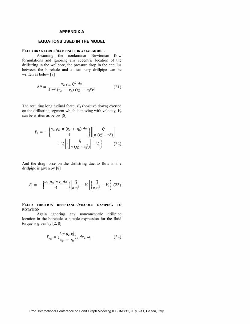
APPENDIX A
EQUATIONS USED IN THE MODEL FLUID DRAG FORCE/DAMPING FOR AXIAL MODEL
Assuming the nonlaminar Newtonian flow
formulations and ignoring any eccentric location of the
drillstring in the wellbore, the pressure drop in the annulus
between the borehole and a stationary drillpipe can be
written as below [8]
∆𝑃 = 𝛼𝑎 𝜌𝑚 𝑄2 𝑑𝑥
4 𝜋2 𝑟𝑤 − 𝑟0 (𝑟𝑤2 − 𝑟0
2)2 (21)
The resulting longitudinal force, FA (positive down) exerted
on the drillstring segment which is moving with velocity, Vn
can be written as below [8]
𝐹𝐴 = − 𝛼𝑎 𝜌𝑚 𝜋 𝑟𝑤 + 𝑟0 𝑑𝑥
4
𝑄
𝜋 𝑟𝑤2 – 𝑟0
2
+ 𝑉𝑛 𝑄
𝜋 𝑟𝑤2 – 𝑟0
2 + 𝑉𝑛 (22)
And the drag force on the drillstring due to flow in the
drillpipe is given by [8]
𝐹𝑝 = − 𝛼𝑝 𝜌𝑚 𝜋 𝑟𝑖 𝑑𝑥
4
𝑄
𝜋 𝑟𝑖2
− 𝑉𝑛 𝑄
𝜋 𝑟𝑖2
− 𝑉𝑛 (23)
FLUID FRICTION RESISTANCE/VISCOUS DAMPING TO
ROTATION
Again ignoring any nonconcentric drillpipe
location in the borehole, a simple expression for the fluid
torque is given by [2, 8]
𝑇𝑅𝑛= (
2 𝜋 𝜇𝑒 𝑟03
𝑟𝑤 − 𝑟0
)𝑛 𝑑𝑥𝑛 𝜔𝑛 (24)
Proc. International Conference on Bond Graph Modeling ICBGMS'12, July 8-11, Genoa, Italy