dynamic modeling and response of soil-wall systems, veletsos and younan
TRANSCRIPT

ui11ILIII-IlilL_ g-----
IlUl_IlUI_Illll-_IIIIl-__

°
BNL-52402
UC-406
. DYNAMICMODELINGANDRESPONSEOFSOIL-WALLSYSTEMS
A.S. Veletsosand A.H. YounanRice University,Houston,Texas
UndercontracttoEngineeringResearch& ApplicationsDivision
Departmentof AdvancedTechnologyBrookhavenNational Laboratory
P.O.Box5000Upton,N.Y.11973-5000
° October1993
PreparedforOFFICEOFENVIRONMENTALRESTORATIONANDWASTEMANAGEMENT
DEPARTMENTOF ENERGY,WASHINGTON,D.C.
DISCLAIMER
Thisreportwas preparedasan accountofwork sponsoredby an agencyoftheUnitedStatesGovernment.Neitherthe UnitedStatesGovernment nor any agencythereof,nor any of theiremployees,nor any of theircontractors,subcontractors,or theiremployees,makes any warranty,expressorimplied,orassumes any legalliabilityorresponsibilityforthe accuracy,completeness,or usefulnessof any information,apparatus,product,orprocessdisclosed,orrepresentsthatitsusewouldnotinfringe
I privately owned rights. Reference herein to any specific commercial product, process,or service by trade name, trademark, manufacturer, or otherwise, does not necessarilyconstitute or imply its endorsement, recommendation, or favoring by the United States .Government or any agency, contractor or subcontractor thereof. The views andopinions of authors expressed herein do not necessarily state or reflect those of theUnited States Government or any agency, contractor or subcontractor thereof.
Printed in the United States of AmericaAvailable from
National Technical Information Service
U.S. Department of Commerce5285 Port Royal Road
Springfield,VA 22161
NTIS pricecodes:
Printed Copy: A04; MicroficheCopy: A01

ABSTRACT
Following a brief review of the errors that may result from the use of a popular model for
evaluating the dynamic soil forces induced in a base-excited rigid wall retaining an elastic
stratum, the sources of the errors are identified and a modification is proposed which
defines correctly the action of the system. In the proposed modification, the stratum is
modeled by a series of elastically supported, semi-infinite horizontal bars with distributed
mass instead of massless springs. The concepts involved are introduced by reference to a
system composed of a fixed-based wall and a homogeneous elastic stratum, and are then
applied to the analysis of more complex soil-wall systems. Both harmonic and transient
excitations are considered, and comprehensive numerical solutions are presented which
elucidate the actions involved and the effects and relative importance of the relevant
parameters.
.
iii
,o

TABLE OF CONTENTS.
Section Page
ABSTRACT iii
TABLE OF CONTENTS v
LIST OF FIGURES vii
EXECUTIVE SUMMARY ix
ACKNOWLEDGMENT xi
1 INTRODUCTION 1-1
2 SYSTEM CONSIDERED 2-1
3 SCO'FI"S MODEL AND ITS ACCURACY 3-l
3.1 A Modification of Scott's Model 3-2
4 PROPOSED MODEL 4-1
5 FUNDAMENTAL SOLUTIONS FOR ELASTICALLY SUPPORTED BARS 5-1
5.1 Bar Impedance 5-1
6 HOMOGENEOUS LAYER WITH IRROTATIONAL WALL 6-1
6.1 Harmonic Response 6-1
6.2 Transient Response 6-2
6.3 Numerical Results 6-3
7 HOMOGENEOUS LAYER WITH ELASTICALLY CONSTRAINED WALL 7-1
" 7.1 Numerical Solutions 7-2
8 INHOMOGENEOUS LAYER WITH ELASTICALLY CONSTRAINED WALL 8-1
9 CONCLUSIONS 9-1
10 REFERENCES 10-1
11 NOTATION 11- 1

LIST OF FIGURES
Figure Page
- 2.1 System considered. 2-3
3.1 Scott's model. 3-4
3.2 Frequency response curves for amplitude of base shear in fixed-basedwall with v = 1/3 and 5 = 0.1. 3-5
4.1 Exact modeling of soil stratum. 4-4
5.1 Stiffness and damping coefficient for semi-infinite elasticallyconstrained bar. 5-4
7.1 Effect of rocking flexibility of wall on distribution of wall pressures for
statically excited systems; uniform stratum with v = 1/3. 7-5
7.2 Effect of rocking flexibility of wall on base shear and moment in wall of
statically excited systems; uniform stratum with v = 1/3. 7-6
7.3 Effect of rocking flexibility of wall on base shear of harmonically excitedsystems; uniform stratum with v = 1/3 and 5 = 0.1. 7-7
7.4 Effect of rocking flexibility of wall on maximum base shear in wall of
systems subjected to El Centro record; uniform stratum with v = 1/3and 8 ffi 0.1. 7-8
8.I Modesof vibrationof a cantilevershear-beamwith a parabolic variationof shearmodulus. 8-5
8.2 Distribution of wall pressures for systems with a rotationally
constrained wall and a medium with parabolic variation in shear modulus;v = 1/3. 8-6
8.3 Base shear and base moment for systems with a rotationally
constrained wall and a medium with parabolic variation in shear modulus;. v = 1/3. 8-7
8.4 Frequency response curves for amplitude of base shear in wall of
systems with uniform, and parabolic variations in shear modulus;v = 1/3 and 5 = 0.1. 8-8
vii

EXECUTIVE SUMMARY
The study reported herein is the third in a series of investigations motivated by the need to gain
improved understanding of the responses to earthquakes of deeply embedded and underground tanks
storing radioactive wastes, and to develop rational but simple methods of analysis and design for such
systems. The first two studies were reported in Brookhaven National Laboratory reports 52357 and
52372.
Probablythesimplestavailableapproximateprocedureforevaluatingthedynamicsoilpressures
inducedby groundshakingon retainingwallsandonembeddedstructuresistheoneproposedin1973
by Scott.Inthisapproach,thefar-fieldresponseofthemedium isevaluatedconsideringittorespond
asa base-excited,verticalcantilevershear-beam,andthedynamicwallpressureata givenheightis
takenproportionaltothedifferenceinmotionsoftheshear-beamandthewallatthatheight.Thisis
tantamounttorepresentingtherestrainingactionofthemedium by a seriesofmasslcss,lincarhori-
zontalsprings.
Following a brief review of the errors that may result from the use of this approach, the sources of the
errors are identified and a modification is proposed which defines correctly the action of the system. In
the proposed modification, the stratum is modeled by a series of elastically supported, semi-infinite
horizontal bars with distributed mass instead of massless springs. The concepts involved are intro-
duced by reference to a system composed of a fixed-based wall and a homogeneous elastic stratum,
and are then applied to the analysis of systems with a wall that is elastically constrained against rota-
tion at its base and a medium for which the shear modulus is either uniform or increases parabolically
with depth. Both harmonic and transient excitations are considered, and comprehensive numerical
solutions are presented which elucidate the actions involved and the effects and relative importance of
the relevant parameters.
Theprincipalconclusionsofthestudymay be summarizedasfollows:
I.The errorsinScott'smodelstemfromitsfailuretoprovidefortheradiationaldampingofthe
medium anditscapacitytotransferforcesverticallyby horizontalshearingactiori.
2.Thedeficienciesofthismodelmay bccliminatcdbymodclingtherestrainingactionofthcmedium
by a seriesofelasticallysupported,semi-infinitehorizontalbarswithdistributedmass ratherthan
bymasslesssprings.The impedanceofeachofthesebarsdependson theratiooftheexcitingfrc-
ix

quency to the natural frequency of the medium for the mode of vibration being considered, and the
material damping factor of the medium. The response of the bars may be evaluated either in the
frequency domain by use of Fourier transform techniques or directly in the time-domain by use of
a convolution integral analogous to Duhamel's integral for single-degree-of-freedom systems.
3. The rotational flexibility of the wall decreases the dynamic wall pressures and the associated shears
and bending moments and affects dramatically their distributions.
4. The greater the wall flexibility, the greater is the number of modes for the medium required to
accurately represent the distribution of dl pressures. However, reasonable approximations to the ..
base forces in the wall may still be obtained considering the contribution of only the first two
modes of vibration for shear and of only the first mode for moment.
5. The magnitude and distribution of the wall pressures are also sensitive to the depthwise variation
of the shear modulus for the medium.
6. The comprehensive numerical solutions presented and their analysis provide not only valuable
insights into the responses of the systems examined and into the effects and relative importance of
the numerous parameters involved, but also a conceptual framework for the interpretation of the
responses of still more complex soil-wall systems.

ACKNOWLEDGEMENT
This study was carried out at Rice University under Grant 568821 from the Brookhaven National
Laboratory, Upton, New York. This support is acknowledged gratefully. Appreciation also is
expressed to Drs. M. Reich and K. Bandyopadhyay for helpful comments and their understanding
project management.
.
xi

SECTION 1t
INTRODUCTION
Probably the simplest available approximate procedure for evaluating the dynamic soil pressures
induced by ground shaking on retaining walls and on embedded structures is the one proposed by
Scott (1973). In this approach, the far-field response of the medium is evaluated considering it to
respond as a base-excited, vertical cantilever shear-beam, and the dynamic wall pressure at a given
height is taken proportional to the relative motions of the shear-beam and the wall at that height. This
is tantamount to representing the restraining action of the medium by a series of massless, linear hori-
zontal springs.
Scott's model has been used extensively (e.g., Karkanias 1983, Dennehy 1984, Jain and Scott 1989,
Alampalli and Elgamal 1991, Soydemir 1991) and variations of it have been employed in analyses of
embedded foundations (Beredugo and Novak 1972, Novak and Beredugo 1972), piles (Novak 1974,
Flores-Berrones and Whitman 1982) and underground cylindrical structures (Miller et al 1991). Pro-
posed originally for an elastic soil stratum retained along its vertical boundaries by a pair of rigid
walls, the procedure is also applicable to the important limiting case of a semi-infinite stratum
retained at one end. The procedure has been applied to rigid and flexible walls as well as to systems
for which the soil modulus increases with depth (Scott 1973, Jain and Scott 1989).
In a recent study of the effects of ground shaking on rigid walls retaining a semi-infinite, viscoelastic
stratum (Veletsos and Younan 1992), it has been shown that, depending on the characteristics of the
ground motion, Scott's model may lead to significant errors. The objectives of the present study are
to: (1) highlight the nature of the inaccuracies that may result; (2) identify their source or sources; (3)
present a modification which correctly describes the action of the system; and (4) use the modified
model for the analysis of different soil-wall systems.
The system investigated is a semi-infinite, viscoelastic stratum of constant thickness that is supported
on a non-deformable rigid base and is retained along one of its vertical boundaries by a rigid wall that
is either fixed or elastically constrained against rotation at the base. Both the wall base and the base of
the stratum are'presumed to be excited by a space-invariant, uniform horizontal motion, q_e concepts
involved are first developed by reference to a uniform stratum and a wall that is fixed against rotation
at its base, and are then applied to the analysis of systems composed of an elastically constrained wall
1-1

and a vertically inhomogeneous medium. The effects of both harmonic and transient excitations are
examined, with special attention paid to the important limiting case of systems excited by very-low-
frequency, essentially static base motions. Comprehensive numerical solutions are presented which
elucidate the actions of the systems considered and the effects and relative importance of the numer-
ous parameters involved.
1-2

I
SECTION 2
SYSTEM CONSIDERED
The system examined is shown in part (a) of Fig. 2-1. It is a semi-infinite, uniform layer of linear vis-
coelastic material that is free at its upper surface, is bonded to a non-deformable, rigid base, and is
retained along one of its vertical boundaries by a rigid wall. The heights of the wall and stratum are
considered to be the same and they are denoted by H. The wall may be either fixed or elastically con-
strained against rotation at its base, the stiffness of the rotational constraint being denoted by R o . The
bases of both the stratum and the wall are presumed to experience a space-invariant horizontal
motion, the acceleration of which at any time t is _g (t). Material damping for the medium is consid-
ered to be of the constant hysteretic type.
The properties of the layer are defined by its mass density, p, shear modulus of elasticity, G, Pois-
son's ratio, v, and the material damping factor, 5, which is considered to be frequency-independent
and the same for both shearing and axial deformations. The latter factor is the same as the tan _5factor
used by the senior author and his associates in studies of foundation dynamics and soil-structure inter-
action (e.g., Veletsos and Verbic 1973, Veletsos and Nair 1975), and twice as large as the percentage
of critical damping. 13,used by other authors in related studies (e.g., Wood 1973, Scott 1973, Arias et
al 1981).
The displacements relative to the moving boundary and the resulting wall pressures and forces for the
base-excited system can be shown to be identical to those of the force-excited system indicated in part
(b) of Fig. 2-1. Both the wall and the base of the latter system are stationary, and the stratum is acted
upon by uniform lateral body forces of intensity -p_, (t). The action of the force-excited system
may in some instances be easier to visualize than that of the base-excited system.
2-1

Y y
t_iiiii!!_!iiiii!ii_iiiiiiiii!iiiii_iiiiiiii!!ii!!iiii!!!_iii_iii!_!i
_i,i_ii!iiiiiii!ii!i!iiiiiiiiiiiiiiii_iiii_ii_iii!iii!iiiiiiiiiii!_I _i,i_li!iiiiii!_!i_iiiii_!ii_!i_i_!_iiiiiiiii!i!i_i_i_i!iii!ii_iii_!!ii_iiiii_i_i_!_i!iiiii_iii!i_!_i!i_i_iii_i_Wall i:_:_:_::]_:_:S::_:_:_:_::_;_@_:_:_:_:_:_:_:_:_:_:_:_:_:_]_:_]_:_:_q_:_:_:_@@_:_H Wall liiiiii!i!i!i_i! iiiiiiii!i_iiiiii!!!i!!!iii!!!i_i!iii_iiii!_iiii_iiiiiiiii!_ii_iii!iii!_ii!i!!ii_!iiiii!_ii!i H
_._______ 1__ ,[!iiiiii_iii!ii_i_iiiiiiiiiiiiii{ii_iiiiii_._i_i_iiiiiiiiiiiiiiiiiiiii_!ii_iii_ii_iiiiiiiiiiiiiiii_.ii_iiiiii_x.',,\\\\\\\'_ Ik_\\_'X\\\\\\\\\\\\\\"_ _ _ _
_g(t)
(a) Ground-Excited (b) Force-Excited
, Fig. 2-1 System considered
t _t

SECTION 3
SCOTT'S MODEL AND ITS ACCURACY
Scott's model for the system is shown in Fig. 3-1. It consists of a vertical cantilever shear-beam that
simulates the far-field action of the stratum, and a set of massless, linear horizontal springs connecting
the shear-beam to the wall. The height and material properties of the beam are taken equal to those of
the stratum, and the stiffness of the springs per unit of length and height of the wall, K_, is taken as
0.8 (l-v) GK, = 1-2v H (1)
This stiffness is the same as the extensional stiffness of a bar of unit cross sectional area and length
2.5H that is fully constrained along its sides. The bases of both the shear-beam and the wall are pre-
sumed to be excited by the same ground motion. The wall pressure at a given height is thus given by
the product of K_ and the relative motions of the shear-beam and the wall at that height. Note that the
spring stiffness is independent of the characteristics of the ground motion and that the only damping
for the model is that involved in the shear-beam itself. Note further that as v _ 0.5, K s and hence
the wall pressures and associated forces for the wall become infinite, a result that is clearly unrealistic.
The rationale for Scott's model may be appreciated by considering first the far-field action of the
medium, namely, the response computed on the assumption that the layer is of infinite extent and that
there is no vertical wall. Each vertical strip of the medium under these conditions responds as an inde-
pendent cantilever shear-beam, and no horizontal pressures develop. The resulting response, which is
independent of the horizontal position coordinate, represents the particular solution of the governing
equation of motion for the medium.
The response of the system with the wall may then be obtained by superimposing on the far-field or
particular solution, the homogeneous solution which accounts for the effect of the normal pressures,
o (11, t), exerted by the wall. The magnitude and distribution of these pressures at any time must be
" such that the end displacements that they induce, along with those induced by th_ ground shaking
under free-field conditions, are equal to the wall displacements.
Let uf be the free-field displacement relative to the moving base of a point located in the medium at a
dimensionless distance 11= y/H from the base, and let w be the corresponding displacement of the
3-1
wall. These displacements are considered to be positive when directed along the positive x-axis. The
normal wall pressures necessary to ensure compatibility of the component displacements along the
wall can then be expressed symbolically by an equation of the form
o (rl, t) = K (_, t) [uf- w] (2)
where K is a generalized impedance or dynamic stiffness for the soil medium, defined in greater
detail in the following sections. For an irrotational rigid wall, w = 0 and the wall pressures are simply
proportional to the far-field motions. Implicit in Eq. (2) is the assumption that only normal pressures o
develop along the wall-soil interface, that the wall can resist both compressive and tensile pressures,
and that the effects of any vertical shearing stresses generated there are negligible.
Since no horizontal pressures develop under free-field conditions, the actual or total wall pressures for
the base-excited system must equal those defined by Eq. (2). It follows that the expression of the wall
pressure as the product of an appropriate stiffness and the difference of the wall motion and the
motion of the medium at the far-field is indeed correct. The uncertainty in Scott's model lies in the
choice of the medium impedance, K.
As a measure of the accuracy of this model, a comparison is made in Fig. 3-2 of the amplitudes of the
steady-state shear at the base of the wall, IQbl,computed by it and two other approaches for a har-
monically excited system. A uniform viscoelastic medium and a wall that is fixed against rotation at
the base are considered. Poisson's ratio and the material damping factor for the medium are taken as
v = 1/3 and 8 = 0.1, respectively. The shear amplitude is normalized with respect to pXgH 2, and
it is plotted as a function of the frequency ratio, co/co_, where co is the circular frequency of the exci-
tation and of the resulting response and coI is the fundamental natural circular frequency of the stra-
tum when it is considered to respond as a cantilever shear-beam. For the homogeneous medium being
examined, the latter frequency is given by
_V s
°)l = 2-'-H (3)
in which v, = _ is the shear wave velocity for the medium. The solid line represents the nearly
exact solution obtained by the approach described in later sections, whereas the short dashed line
defines Scott's solution. The accuracy of the latter solution is clearly not satisfactory. Note in particu-
lar that, whereas the exact solution leads to significantly larger base shears than Scott's solution at the
low and high values of the frequency parameter, the opposite is true in the intermediate range of the
frequency parameter for which co/o_1 is close to unity.
3.1 A Modification of Scott's Model
The discrepancies in Scott's solution are due, in part, to the failure of the model to provide for the
3-2
radiational damping capacity of the medium. If instead of a series of massless, horizontal linear
springs, the medium were approximated by a series of infinitely long, linear horizontal bars with uni-
formly distributed mass, it is well known (see, for example, Wolf 1988) that the action of such bars for
a harmonic base motion would be identical to that of a series of dashpots. On the assumption that the
bars are constrained laterally and that their horizontal faces are stress-free, the equivalent damping
coefficient of the dashpots, c, is given by
The curve in long dashed lines in Fig. 3-2 represents the frequency response curve for the base shear
in the wall computed on the assumption that the medium can be modeled by a series of horizontal
dashpots rather than massless springs. It is observed that, while at high values of the frequency param-
eter, the latter modeling of the medium is definitely superior to that of the original Scott model, it too
leads to unacceptable results in the lower frequency range.
3-3

Fig. 3-1 Scott's model
3-4

Fig. 3-2 Frequencyresponsecurvesfor amplitudeof base shearin• fixed-basedwall;uniformstratumwithv = 1/3and 5 = 0.1
3-5

SECTION 4
PROPOSED MODEL
B
Both models referred to above are deficient in that they fail to provide for the capacity of the medium
to transfer forces vertically by horizontal shearing action. In addition to the horizontal normal stresses
and inertia forces, a horizontal element of the medium is acted upon along its upper and lower faces
by horizontal shearing stresses, as shown in part (a) of Fig. 4-1, the difference of which, AX, is given
by
c3'txy 1 _)'CxyA,c= = (5)
On the assumption that the horizontal variation of the vertical displacements is negligible, -- a quite
reasonable approximation --, Xxycan be expressed as
G_u
'l:xy = _--_ (6)
in which u is the horizontal displacement of the medium relative to the moving base. On substituting
Eq. (6) into Eq. (5), one obtains
A't - (7)HZ_rl 2
Now, let the displacement u be expressed by the method of separation of variables as a linear combi-
nation of modal terms, as
OlO
u (_, _, t) = _ X.(_) Yn(_) %(0 (8)- n=|
in which _ = x/H is the horizontal dimensionless position coordinate, and Xn, Yn and qn are func-
tions of _, TI and t, respectively. The nth component of A'c, denoted by (Ax) n, may be then
expressed as
G X,(_) Y'_(rl) (9)(Ax)n = n--_ qn(t)
which, on letting u, (_, rl, t) represent the nth term of the right hand member of Eq. (8), can also be
4-1

written as
Y°_(n) G
(A1;)n = Yn(Tl) H2 Un(_'rl' t) (10)
For the uniform stratum under consideration,
(2n- 1)_Yn (1"1)= sin 2 _ (11) "
and (AI:) n reduces to
I (2n- _ 1)_t] 2G(A_) n = - _-_ U,,(_, T1,t) (12)
The multipliers of un (_, _, t) in Eqs. (10) and (12) are now recognized to equal pto2 where ton, the
nth circular natural frequency of the stratum responding as a cantilever shear-beam, is given by
n_v sto - (13)
n 2H
Accordingly, Eqs. (10) and (12) can also be written as
(A1;)n = _p (02nUn(_' lq, t) (14)
Equations (12) and (14) represent a force per unit of length that is proportional and opposite to un, the
constant of proportionality being independent of the position coordinates and a function only of the
order n of the response component being considered. Furthermore, this force is identical to that
induced by a massless linear spring of stiffness
k n ---- Oton2 _-- [(2n-1)_ 2G.1 _-_ (15)
It follows that, for each modal component of response, the horizontal shearing action of the medium
may be represented by a set of horizontal linear springs of constant stiffness k n, and that the medium
may be modeled by a series of semi-infinitely long, elastically supported horizontal bars with distrib-
uted mass, as shown in part Co) of Fig. 4-1. The lower ends of all the springs are presumed to be
attached to the common base experiencing the prescribed ground acceleration, _s (t). In reality, the
response of only a single bar needs to be evaluated for each modal component, as the responses of all
the other bars are proportional to sin[ (2n- 1)gT1/2 ] .
The steps involved in the evaluation of the response of the stratum may now be summarized as fol-lows:
1. Compute the response of the semi-infinitely long, elastically supported bar with distributed mass
considering the spring stiffness to have the value obtained from Eq. (15) with n = I.
4-2

2. Determine the corresponding response of the stratum at a dimensionless distance rl from the base
by multiplying the bar response by sin[ (2n - 1) nrl/2 ] .
3. Repeat steps 1 and 2 for the higher values of n, as necessary, keeping in mind that a change in n
affects both the spring stiffness kn and the associated natural frequency o n, as well as the height-
wise variation of the resulting response. It should further be recalled that the response compo-
nents for the higher values ofn are likely to be insignificant (Veletsos and Younan 1992) and may
not have to be considered.
4. Obtain the total response from Eq. (8) by superposing the component responses.
The responses obtained by this approach are identical to those obtained by the method of analysis for
the stratum presented by Arias et al (1981). They are also identical to those which would have been
obtained from the analysis presented by Veletsos and Younan (1992) if, in addition to assuming the
absence of any vertical normal stresses, the horizontal shearing stresses had been expressed by Eq. (6)
rather than by the more precise expression
G 0u 0v
Xxy= _ Ig-_ +_ (16)
The interrelationship of these solutions is considered further in a later section.
It is important to observe that the natural frequency of the bar in the proposed model corresponds to a
mode of vibration in which the bar moves as a rigid body on springs of stiffness kn per unit of length.
The circular value of this frequency, J-kn/p, is identical to the nth natural frequency of the stratum
defined by Eq. (13).
4-3

_'Cxy
dY"r''''-'_'--'_.4-1 _ "-'--'_ ---'-'_
_xy
(a) State of Shearing Stresses
xElastic Bar with Distributed Mass,,,,--
_ oeeo eole eeoe
kn ] kn kn_////////////////////////////////////, _/////III//I/Iil/I/II///Z. '//11//i//_
(b) Elastically Constrained Bar
Fig. 4-1 Exact modeling of soil stratum
4-4

SECTION 5 f+ I
FUNDAMENTAL SOLUTIONS FOR ELASTICALLY SUPPORTED BAR
The evaluation of the dynamic response of the semi-infinitely long, elastically supported bar with
mass is a fundamental problem in foundation dynamics which has already been addressed in the liter-
ature (e.g,, Wolf 1988). For an undamped elastic bar of unit cross sectional area that is stress free
along its upper and lower faces and fully constrained in the lateral direction, the governing equation of
motion is
knU = p_-t2 (17)
in which u represents the displacement of an arbitrarypoint relative to the moving base, 1_represents
the laterally constrained modulus of elasticity of the bar, given by
_ E _ 2G (18)1 -v 2 1 -v
and E = 2 ( 1 + v) G is Young's modulus of elasticity of the bar material. For a dissipative bar with
frequency-independent, constant hysteretic damping, the real-valued shear modulus G in the expres-
sions for kn and I_ in Eq. (17) should be replaced by the complex-valued modulus G* = G ( 1 + _5),
in which i : _"i'.
5.1 Bar Impedance
Defined for a bar in harmonic motion, the impedance or dynamic stiffness of the bar, Kn, represents
the amplitude of the harmonic end force necessary to induce a steady-state end displacement of unit
amplitude. This is a complex-valued quantity that depends on the characteristics of the bar and the fre-
quency of the excitation. For a viscoelastic bar with frequency-independent damping,i,
Kn = (K,t) n_/( I + i8) ( 1 - _2 + i5) (19)a
in which (Kst) n denotes the static stiffness, defined as the static end force necessary to induce a unit
end displacement, and _n denotes the dimensionless frequency ratio co/co n. The square root sign in
the latter expression and in the equations that follow refers to the first square root of t'ae enclosed
complex-valued quantity. The static stiffness is defined by
5-1

(K,t) n = _o G,_n (20)
which, on makinguse of Eq. 05), can also be writtenas
(2n- 1)_o G(K_t)n - 2 _ (21)
and
_o = _ (22) .
Equation09) isdeducedfromthecorrespondingcquationfora latcrallyfrcc,undampedbarpre-
sentedbyWolf(1988)byreplacingE by E andthcreal-valuedshcarmodulusG intheexpressions
for(K,t)n and0n bythecomplcx-valucdmodulusG*.Thisequationmay moreconvenientlybeexpressedas
Kn = (Z,t)n(C_n+f0n_n) (23)
whereanand_naredimensionlessfactorsthatdependonthefrequencyratio,0n,andthematerial
damping factor, 8. Note that the stiffness k. of the supportingsprings in these expressions appears
throughEq. (20) in (K,t) n and through con -- _ in On, 0_nand [3n. It should also be noted that
to each value of n there correspondsa differentvalue of k n and a different value of o)n.
The realpart of Eq. (23) representsthe fo_.cecomponent that is in phase with the cxcitation, whereas
the imaginary pan represents the component that is 90° out of phase. In the conventional spring-dash-
pot representation of the restrainingaction of the medium, the stiffness of the spring is represented by
the real part of Eq. (23), and the coefficient of theviscous damper, cn, is related to _n by
cn_-[3n(Z,t)n_-[]n¥oG.f_ (24)f.on
Thefactorsocnand]3nwillbcreferredtoasthestiffnessanddampingcoefficients,respectively.
Fig.5-Ishowsthevariationsofocnand[3nasafunctionofthefrequencyratio,On,forseveraldiffer-
entvaluesofthematerialdampingfactor,8,Alsoshownforthespecialcaseofanundampedmedium
arethecorrespondingcurvesobtainedforScott'smodelforavalueofn = I andv --I/3,andfor
themodelinwhichtheactionofthemediumisrepresentedbyasetofviscousdampers.Thelackof
correlationbetweentheresultsobtainedbythelattertwomodelsandtlmexactmodelneednotbe
overemphasized.
For a non-dissipativemediumand values of 0n < 1 (i.e., forexciting frequencieslower than the natu-ral frequency of the stratumfor the mode of vibrationbeing considered), the damping coefficient
[_n= 0, indicatingthe absenceof radiationdampingin this range.By contrast,for On_ I, the damp-
5-2

ing coefficient is finite but the stiffness coefficient a n - 0. These are well known facts that have been
noted before by Wolf (1988) and by Meek and Wolf (1991) among others.
5-3

i
Exact Model
1.2 ....... Scott's Model, n = 1 1.2Model withDampers Only ..................................
0.8 0.8 0.2
0_ ...................... _n 0.1n
-0.4 (a) -0.4 (b)
Fig. 5-1 Stiffness and damping coefficients for semi-infinite elastically constrained bar
I i
I

SECTION 6
HOMOGENEOUS MEDIUM WITH IRROTATIONAL WALL
6.1 Harmonic Response
With the impedance of the bar established, the steady-state response of the bar to a harmonic base
motion and the corresponding response of a homogeneous stratum may be evaluated readily. Let
uf (11,t) be the instantaneous value of the far-field, horizontal steady-sta_ displacement relative to
the moving base of a point of the stratum located at a dimensionless distance 11 = y/H from the
base. This displacement may be expressed by the superposition of modal components (see, for exam-
ple, Veletsos and Younan 1992) as
m
in which
16 P_:sH 2 1 1
Un = _3 G (2n-1)31-¢_2+i5 (26)
The wall pressure at an arbitrary elevation may then be obtained by multiplying each displacement
component by the corresponding bar impedance defined by Eq. (19). On so doing, one obtains
¢_(_,t) =
(27)
8 " l [ (2n- l)_n]=- _,p:_s H _ 1 1 + i________sin ei_'t
;t" ,,-x (2n-l) 2 l-tpn2+_$ 2
- The shear and bending moment in the wall is finally determined by integration. In particular, the base
shear per unit of wall length. Qb (t), is given by
lQb(t) = G(ll.t) Hdr]0
(28)
_ I_.¥Oo.X, H2 L 1 l 1+i8 ei_,,,=l (2n-l) 3 1-_+i5
6-1

and the corresponding base moment, Mb (t), is given by
M b (t) = I ff (1], t) H2rldrl0
(29)
- =" - ,,=, iTn-li4 l_t_2+i8 e
Pressures are considered to be positive when tensile; a shearing force acting on the base is positive
when directed along the positive x-axis; and the corresponding base moment is positive when clock-
wise.
Equations (27) through (29) may be reduced to the corresponding expressions presented by Veletsos
and Younan (1992) simply by replacing the factor Vo by the factor
2 (30)Vo = d(l-v) (2-v)
For v = 1/3, the ratio of _o/_o = 0.913. In the development of these equations no provision has
been made for the inertia effects of the wall mass. For the rigid, irrotational wall considered, the addi-
tional base shear and moment due to the wall inertia are given simply by -}_XsH and -gXsH2/2,
respectively, in which }_= the mass per unit of plan area of the wall.
The values of K, in Eqs. (27) through (29) are different for the different terms of the series. However,
for systems such as the one examined in this section for which the response is clearly dominated by
the fundamental mode of vibration (note the rapid convergence of the results with increasing n),
excellent approximations to the base shear and base moment may be obtained by replacing Kn by K l
and merely multiplying the appropriate far-field response by K I.
6.2 Transient Response
With the harmonic response of the elastically supported bar and of the associated stratum established,
their response to an arbitrary transient excitation may be evaluated by Fourier transform (DFT) tech-
niques. The following steps are involved in the implementation of this approach: (1) Evaluate the
Fourier transform of the ground acceleration, _s (t) ; (2) compute the product of this transform andthe complex-valued transfer function of the desired response; and (3) obtain the desired transient
response by taking the inverse Fourier transform of the latter product. The Fourier transforms are typ-
ically computed as discrete Fourier transforms using the fast Fourier transform (FI=T.)algorithm and
appending a sufficiently long band of zeros at the end of the forcing function so as to eliminate or
reduce the aliasing errors that may be introduced (Veletsos and Ventura 1985). For the solutions pre-
sented herein, the duration of this band was taken equal to 10 times the fundamental natural period of
the layer idealized as a cantilever shear-beam.
6-2

The response to an arbitrary excitation of the elastically supported bar may also be evaluated from an
integral expression analogous to Duhamel's integral for single-degree-of-freedom systems. The
dynamic end pressure o n (t) in this approach may be expressed as
8_o 1
, o n(t) = _2 oH _ An(t) (31)
where An(t ) is a pseudo-acceleration function which, for a non-dissipative elastic medium, is given
" by
t
An (t) = ton I _m(x) Jo [con(t- x) ] d, (39..)
and Jo is the Bessel function of the first type and zero order. This expression appears to have been first
presented by Kotsubo (1959) (see also Arias et al, 1981). The wall pressure at an arbitrary elevation
may then be determined from
o(rl, t) = ,--:_°n(t) sin[ (2n-1);t]2 rl (33)
The numerical solutions obtained herein were obtained by the DFT approach.
6.3 Numerical Solutions
Comprehensive numerical solutions for the pressures, shears and moments induced by ground shak-
ing in rigid wails have been presented in Veletsos and Younan (1992) for both harmonic excitations
and the intense segment of an earthquake ground motion record. The reader is referred to that publica-
tion for an account of the magnitude and distribution of these effects and for an assessment of the
effects and relative importance of the various parameters involved. Included in this publication also
are comparisons with solutions obtained by use of the Scott model. It should be recalled that the data
reported in Veletsos and Younan (1992) are _o/Wo times as large as those obtained by the model pre-
sented herein and by the analysis presented by Arias et al (1981).
6-3

I
SECTION 7g
HOMOGENEOUS MEDIUM WITH ROTATIONALLY CONSTRAINED WALL
The rigid wall in this section is presumed to be elastically restrained against rotation at the base by a
spring of stiffness R0, and consideration is given to the steady-state response of the system to a har-monic excitation of the base.
The instantaneous value of wall rotation, positive when clockwise, is given by
0 (t) = O ei_°t (34)
in which O is its complex-valued amplitude, and the horizontal displacement of the wall at a dimen-
sionless distance 1"1= y/H from the base is given by
w (1"1,t) = Orl H e/t°t (35)
When expanded in terms of the natural modes of vibration of the stratum, Yn (11), Eq. (35) can bewritten as
w (rl, t) = nX--,W. sin [ (2n- l)g2 11]ei_°' (36)
in which
8 (-1) n-I
Wn _2 (2n- 1) 2 OH (37)
In the spirit of Eq. (2), the instantaneous wall pressure may then be expressed as
oo
o(rl. t) = X K.[U.,- Wn] sin I (2n- 1)7trl I ei_O, (38,nffil 2
in which the terms involving the displacements Un represent the pressure induced on a fixed-base
wall and are given by Eq. (26), and the remaining terms represent the contribution of the wall rotation.
The rotation amplitude O in Eq. (37) may be determined from the equilibrium of moments around the
wall base,
7-1

1 -32.,,
Mb_OM/__° 1 I,tH2_s + 3 _tH COt_ = RoO (39)
in which Mb is the moment amplitude induced by the pressures exerted on the fixed-base wall defined1
by Eq. (29); and Mb is the corresponding amplitude induced by the pressures associated with a unit
rotation of the Wall. The latter moment is given by
1 32H3 ,_, 1 KnMb- _-_ I-,(2n-i)4n-I
(40)
_16 2_ 1 J- n-__oGH ( 1 + i8) ( 1 - _ + i8)I (2n- 1) s
The remaining two terms on the left-hand member of Eq. (39) represent the contribution of the wall
inertia. With the rotation amplitude O evaluated, the complex-valued amplitude of the base moment
isgivenby theproductR00.
The instantaneous base shear in the wall may similarly determined from
[r ,1 _l.H2t,020] eitOt= LQo- OQo- _nj(, + _ (41)Qb(t)
in which Q_, the complex-valued amplitude of the component due to the pressures acting on a fixed-
base wall, is determined from Eq. (28); and Q_, the corresponding amplitude of the component due to
the pressures associated with a unit rotation of the wall, is given by
1Q:= 6H2_ (-1) n-'
It3n=l (2n-" ;i-3Kn(42)
= n_VoGHn_., (-l)n-', (2n-i; J(1
Examination of Eqs. (39) through (42) reveals that, in addition to the parameters governing the
response of the system with the fixed-based wall, the dynamic response of the elastically constrained
wall depends on the relative mass densities of the two components, g/oH, and the dimensionlessmeasure of the relative flexibilities of the wall and the medium,
GH 2
do - R0 (43)
7.1 Numerical Solutions
Static Effects. It is desirable to examine first the responses obtained for excitations the dominant fre-
quencies of which are small compared to the fundamental natural frequency of the stratum (i.e., for
7-2
motions with _1 -* 0). Such excitations and the resulting effects will be referred to as static and willbe identified with the subscript st. This term should not be confused with that normally used to repre-
sent the effects of gravity forces. In the equivalent, force-excited version of the problem shown in part
Co)of Fig. 2-1, the static excitation is represented by a set of horizontal body forces of constant inten-
sity -PXs"
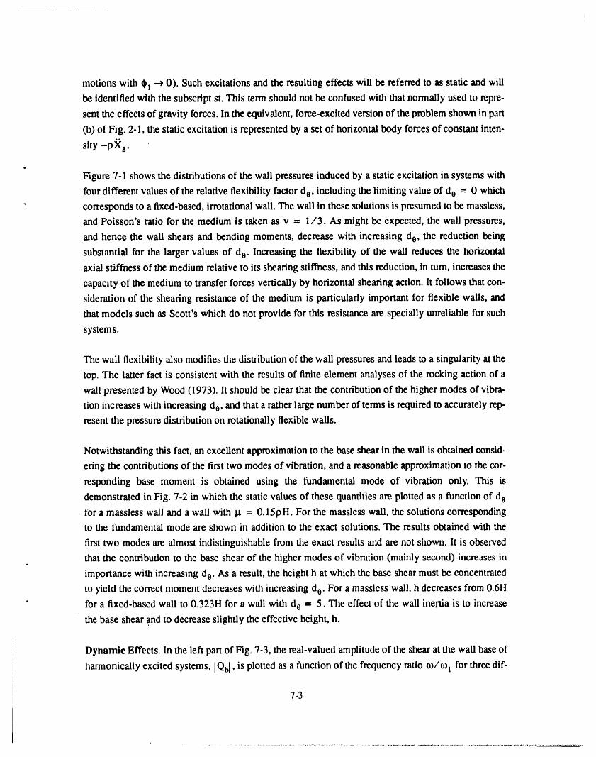
Figure 7-1 shows the distributions of the wall pressures induced by a static excitation in systems with
four different values of the relative flexibility factor de, including the limiting value of do - 0 which
" corresponds to a fixed-based, irrotational wall. The wall in these solutions is presumed to be massless,
and Poisson's ratio for the medium is taken as v = I/3. As might be expected, the wall pressures,
and hence the wall shears and bending moments, decrease with increasing do , the reduction being
substantial for the larger values of do . Increasing the flexibility of the wall reduces the horizontal
axial stiffness of the medium relative to its shearing stiffness, and this reduction, in turn, increases the
capacity of the medium to transfer forces vertically by horizontal shearing action. It follows that con-
sideration of the shearing resistance of the medium is particularly important for flexible walls, and
that models such as Scott's which do not provide for this resistance are specially unreliable for such
systems.
The wall flexibility also modifies the distribution of the wall pressures and leads to a singularity at the
top. The latter fact is consistent with the results of finite element analyses of the rocking action of a
wall presented by Wood (1973). It should be clear that the contribution of the higher modes of vibra-
tion increases with increasing d0, and that a rather large number of terms is required to accurately rep-
resent the pressure distribution on rotationally flexible walls.
Notwithstanding this fact, an excellent approximation to the base shear in the wall is obtained consid-
ering the contributions of the first two modes of vibration, and a reasonable approximation to the cor-
responding base moment is obtained using the fundamental mode of vibration only. This is
demonstrated in Fig. 7-2 in which the static values of these quantities are plotted as a function of do
for a massless wall and a wall with _t = 0.15pH. For the massless wall, the solutions corresponding
to the fundamental mode are shown in addition to the exact solutions. The results obtained with the
first two modes are almost indistinguishable from the exact results and are not shown. It is observed
that the contribution to the base shear of the higher modes of vibration (mainly second) increases in
importance with increasing d0. As a result, the height h at which the base shear must be concentrated
to yield the correct moment decreases with increasing do. For a massless wall, h decreases from 0.6H
for a fixed-based wall to 0.323H for a wall with d o = 5. The effect of the wall inertia is to increase
the base shear and to decrease slightly the effective height, h.
Dynamic Effects. In the left part of Fig. 7-3, the real-valued amplitude of the shear at the wall base of
harmonically excited systems, [Qbl, is plotted as a function of the frequency ratio to/to I for three dif-
7-3

ferent values of the relative flexibility factor d0. The results are normalized with respect to pXsH 2.
The wall in these solutions is presumed to be massless, and Poisson's ratio and the material damping
factor for the medium are taken, as before, as 1/3 and 0.1, respectively.
As would be anticipated from the static solutions presented in Fig. 7-2, the rocking flexibility of the
wall base decreases the base shear. However, the decrease is by no means uniform over the full range,b
of frequencies considered. In particular, the reduction is substantially smaller at and near resonance
than under static conditions of loading. The interrelationship of the dynamic and static responses may
better be appreciated from the fight-hand plots of Fig. 7-3, in which the ratio of the maximum
dynamic to the corresponding static shears (the amplification factor) is plotted as a function of the fre-
quency ratio for the same three values of the relative flexibility parameter do. Of special interest are
the values of the ratio at first resonance. For the fixed-base irrotational wall, it is well known that the
resonant amplification factor is given by l/,f8 (see Arias et al, 1981, and Veletsos and Younan,
1992), which equals 3.16 for the value of _i = 0.1 considered. By contrast, for the rotationaUy flexi-
ble wail, this factor is substantially larger. This is due to the reduced capacity of the flexible wall to
reflect and dissipate by radiation the waves that are transmitted to it. As d o --, 0, the medium tends to
respond as an unconstrained shear-beam, and the amplification factor at resonance approaches the
value of 1/5 = 10 which is applicable to a viscously damped single-degree-of-freedom oscillator.
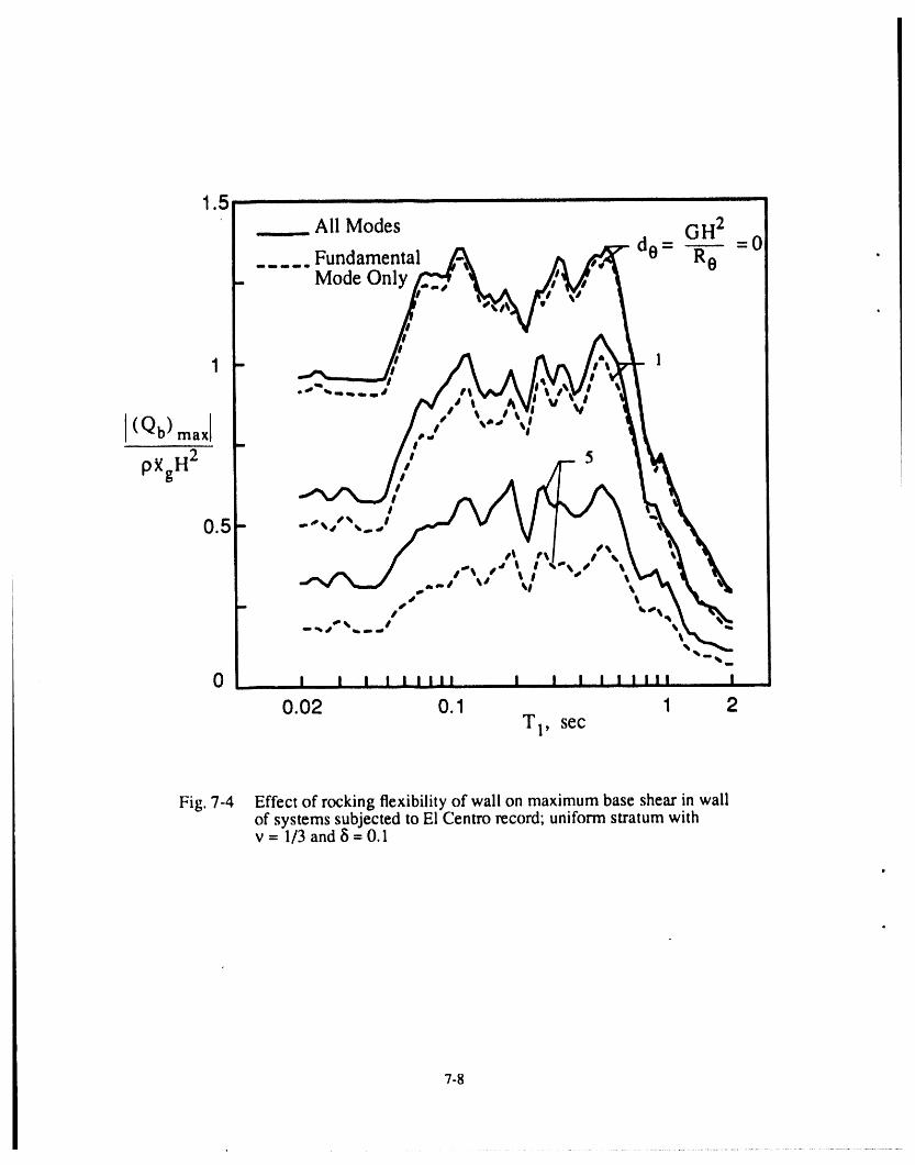
The same general trends also are observed in Fig. 7-4 which presents normalized values of the maxi-
mum base shear induced in the wall of a system excited by the first 6.3 sec of the N-S component of
the E1 Centro, California earthquake of 1940. The acceleration, velocity and displacement of this
record have been presented in Veletsos and Tang (1990) and are not reproduced here. The peak value
of the ground acceleration is Ks = 0.312 g, and the corresponding values of the velocity and dis-
placement are _s = 14.02 in/sec and xs = 8.29 in. The absolute maximum value of the base shear,
[ (Qb) max[' is normalized with respect to pRs H2 arid plotted as a function of T 1 = 2_t_ 1, the funda-
mental natural period of the layer idealized as a shear beam. As a measure of the values of TI that
may be encountered in practice, it is noted that for shear-wave velocity values for the soil in the range
between 400 and 1600 ft/sec and for values of H in the range between 10 and 50 ft, the value of T l
fails in the range of 0.025 sec to 0.5 sec. Also shown in dashed lines are the corresponding results
obtained by considering the contribution of only the fundamental mode of vibration. Note that the
flexibility of the wall reduces the resulting base shear, but that the reduction for a given value of do is J
not nearly as large for the higher values of the plots as they are for the static values. Note further that
the contribution of the higher modes of vibration (mainly second) increases in importance with
increasing do.
7-4
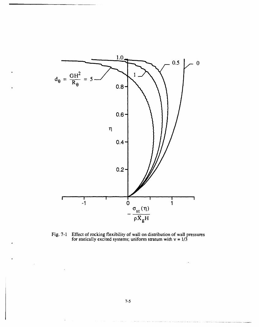
Fig. 7-1 Effectof rockingflexibilityof wallon distributionof wallpressuresfor staticallyexcitedsystems;uniformstratumwithv = 1/3
p
7-5

1.2 1 0.6l
(Qb) st _ (Mb) st All ModesP_gH 2 PXg H3 ....... FundamentalMode Only
110.8 pH - 0 0.4
g -0pH
• 0.5
"-' " 0.5b, •
0.4 ".. 0.2%
0 , , , , , 0 , , , , ,.0 1 2 3 4 5 0 1 2 3 4 5
de = GH2/Re de = GH2/Re
Fig. 7-2 Effect of rocking flexibility of wall on base shear and moment in wall of statically excited systems;uniform stratum with v = 1/3
II

3 - GH2 6 - GH2
do = R0- 0 d0- R0- 5
1" 1
2 5 4-
IQbl 0
.kl
1 2
0 It II li I II li II '.
,0 1 2 3 4 0 1 2 3 4t_/to 1 m/t,o1
Fig. 7-3 Effect of rocking flexibility of wall on base shear of ham_nically excited systems;uniform stratum with v = 1/3 and 8 = 0.1
1 5 -i ii IlIIIIIIIIIErT I I II I I I I II IIIIIIIIIIIIII II I
_ All Modes GH 2
..... Fundamental de- Re - 0 ._ Mode Only
Q
Fig. 7-4 Effect of rocking flexibility of wall on maximum base shear in wallof systems subjected to El Centro record; uniform stratum withv = 1/3 and 8 = O.1
7-8

SECTION 8,11
INHOMOGENEOUS MEDIUM WITH ROTATIONALLY CONSTRAINED WALL
o
Consideration is now given to an inhomogeneous medium for which the vertical variation of the shear
modulus is defined by
0 (1])= Oog(11) (44)
in which g (11) is a dimensionless, decreasing function of 1] with g (0) = 1, and GOrepresents the
base value of the shear modulus. The mass density of the medium, p, ,is considered to be constant,
and the wall base is considered to be elastically constrained against rotation.
The method of separation of variables employed in the solutions presented so far is not applicable in
this case. As a result, the stiffnesses kn of the supporting springs in the modeling of the medium by
elastically supported bars are in reality functions of both the _- and rl-coordinates. However, a rea-
sonable approximation to the solution may again be obtained considering the values of kn to be con-
stant and determining them from the left-hand member of Eq. (15). The frequency 03 in this case
must be interpreted to be the nth circular natural frequency of the inhomogeneous stratum vibrating
as a cantilever shear-beam. The following considerations justify this approximation: (1) When vibrat-
ing freely in its nth natural mode, Yn(11), the difference of the shearing stresses acting on the upper
and lower faces of a horizontal strip of the medium is given by Eq. (14), and Eq. (15) is exact under
these conditions; and (2) for the limiting case of a statically excited medium, the solution obtained
with the proposed approximation was found to be in good agreement with a more elaborate finite ele-ment solution.
As an example, consider a medium for which G increases parabolically with depth as
, G(11) = Go[l-1] 2] (45)
The nth natural mode of vibration of this medium is given by Bielak (1969)
" Yn(11) = P2n- 1 (11) (46)
in which :he right-hand member represents the Legendre polynomial of order 2n- 1, and the associated
circular frequency is given by
8-1

H
where(v,)o= G,__o/Pisthebasevalueoftheshearwavevelocityforthemedium.Fig.8-Ishowsthefirstthreemodesofvibrationofthemedium.Noticethatthetopvaluesofthesemodesareunity,
andthatthefundamentalmodeincreaseslinearlyfromzeroatthebase.Accordingly,inanexpansion
ofthedisplacementoftherigidwallintermsof Yn(_), only thefundamentalmodewillbeinvolved.
Thespringconstantskninthiscasearedeterminedfromtheleft-handpartofF-4.(15)tobe
Go
kn = 2n(2n- I)_-_ (48)
and,onmakinguseofEqs.(19)and(20),theimpedanceoftheelasticallysupportedbarisfoundtobe
afunctionoftheverticalpositioncoordinateH andexpressibleas
K n (n) = [Kst (11)]n [°in4-l_n_n] (49)
Inthelatterequation
¥oGo _ _2[K,t(_)]. = ,/2n(2n- I) _ - (50)
andcxnand[_narethedimensionlessimpedancecoefficientsdisplayedinFig.5-I,inwhichconinthe
expressionfor)nmustnow beinterpretedtobethenthcircularnaturalfrequencyoftheinhomoge-neousstratum.
For a harmonicallyexcited system, the complex-valued amplitude of the nth modal component of the
steady-state displacement of the medium at the far-field, Un, is given by
Cn 1 pXg H2Un = (51)
2n(2n-l) 1-¢_+f8 GO
in which
IYn(13)dq _f_(4n - I)o (52) "
Cn = _ = 2 F(l.5-n) F(n+ 1)JYne(q)drl0
andF istheGamma function.TheintegralsinEq.(52)wereevaluatedfromexpressionsgivenin
AbramowitzandStegun(1965),andGradshteynandRyzhik(1965).The factorsCn representthe
coefficients in an expansion of the unit function in terms of the natural modes of the stratum and,
therefore, add up to unity. The first four values of Cn are 1.5, -0.875, 0.6875 and -0.5859, respec-
8-2

tively.
Recalling that the wall displacement, just like the fundamental mode of vibration of the medium,
increases linearly from base to top, the wall pressure at a normalized height rl may be written in theform
I " 1o(vl,t) = 1(rl)[UI-eH]_ + _ Kn(_)UnYn(n) e_)' (53)n-2
inwhich YB (H) isdefinedby Eq.(46),K n(_) and U n aredeterminedfromEqs.(49)and(51),
respectively,and O iscomputed,asbefore,fromEq.(39).The integralsofY, involvedintheexpres-
sionsforM_)and M_ inF_,q.(39)andintheexpressionsforQ_ andQ_ inEq.(4I),wereevaluatedby
numerical integration.
It is clear from Eq. (53) that, as the flexibility of the wall constraint and hence O increase, the first
term on the right-hand member of Eq. (53) decreases, while the remaining terms, being independent
of O, remain the same. It follows that the greater the flexibility of the wall constraint, the greater is
the percentage contribution of the higher modes of vibration to the resulting wall pressures and the
associated forces. The plots in solid lines in Fig. 8-2 show the exact distributions of the wall pressures
for statically excited systems, whereas the dashed lines show those computed by considering the con-
tribution of only the fundamental mode of vibration of the stratum.The results are for a massless wall
and a medium with v = 1/3. Three different values of the relative flexibility factor
GavH2
d o = Ro (54)
are considered, in which Gay = (2/3) Go is the average shear modulus of the medium. Note the fol-
lowing:
1. Unlike the pressure distributions for the homogeneous medium presented in Fig. 7-1 which for
the rotationally flexible walls exhibit a singularity at the top, the top values of the pressures fori'
the inhomogeneous medium are zero.
2. The pressure distributions in Fig. 8-2 bear no resemblance to the inverted triangular distribution
reported for the same problem by Scott (1973).
• 3. As already inferred from Eq. (53), the contribution of the higher modes of vibration relative to
that of the fundamental increases in importance with increasing flexibility of the wall constraint.
However, reasonable approximations for the base shear and base moment in the wall may still bea
obtained from the first two or only the first mode of vibration.
The static values of the base shear and base moment for a medium with a parabolic variation in G are
compared in Fig. 8-3 with those obtained for a homogeneous medium with a value of G = G,,,. Note
that the effects for the equivalent homogeneous medium are substantially larger than for the inhomo-
8-3
geneous medium.
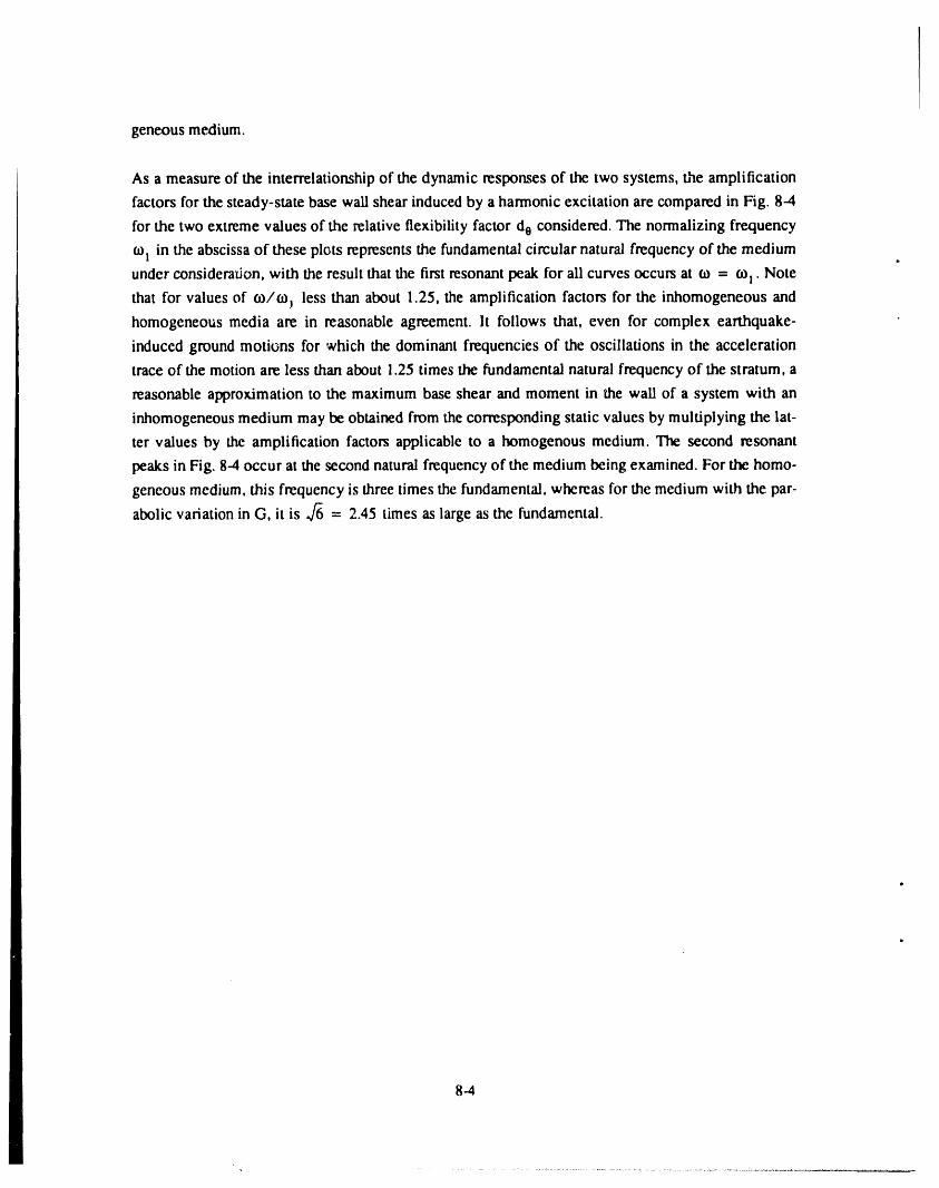
As a measure of the interrelationship of the dynamic responses of the two systems, the amplification
factors for the steady-state base wall shear induced by a harmonic excitation are compared in Fig, 8-4
for the two extreme values of the relative flexibility factor do considered. The normalizing frequency
coI in the abscissa of these plots represents the fundamental circular natural frequency of the medium D
under consideration, with the result that the first resonant peak for all curves occurs at ¢o = co! . Note
that for values of co/e, less than about 1.25, the amplification factors for the inhomogeneous and
homogeneous media are in reasonable agreement. It follows that, even for complex earthquake-
induced ground motions for which the dominant frequencies of the oscillations in the acceleration
trace of the motion are less than about 1.25 times the fundamental natural frequency of the stratum, a
reasonable approximation to the maximum base shear and moment in the wail of a system with an
inhomogeneous medium may be obtained from the corresponding static values by multiplying the lat-
ter values by the amplification factors applicable to a homogenous medium. The second resonant
peaks in Fig. 8-4 occur at the second natural frequency of the medium being examined. For the homo-
geneous medium, this frequency is three times the fundamental, whereas for the medium with the par-
abolic variation in G. it is ,f6 = 2.45 times as large as the fundamental.
8-4

3 2 n=l0.8
-0.5 0 0.5 1.0
Yn (13)
Fig. 8-I Modes of vibration of a cantilever shear-beam witha parabolic variation of shear modulus.
8-5


r •
, I U I I e 0 ! ! I I m
0 1 2 3 4 5 0 1 2 3 4 5
Gav H2/Re GavH2/Re
Fig. 8-3 Base shear and base moment for systems with a rotationally constrained wall and a medium withI parabolic variation in shear modulus; v = 1/3fl
!

6" i_ •
iI H2II Gayi iI _ 5 •
, R05-
im
0m 3-
Parabolic G
< ..... Uniform G2-
m
%
_,mw R _
0 ' I i I I I I
0 1 2 3 ';,6O/O)1
Fig. 8-4 Frequency response curves for amplitude of base shear in wall of osystems with uniform, and parabolic variations in shear modulus;v -- 1/3 and _i= 0.2
8-8
SECTION 9
CONCLUSIONS
The principal conclusions of the study may be summarized as follows:
1. The errors in Scott's model stem from its failure to provide for the radiational damping of the
medium and its capacity to transfer forces vertically by horizontal shearing action.
2. The deficiencies of this model may be eliminated by modeling the restraining action of the medium
by a series of elastically supported semi-infinite horizontal bars with distributed mass rather than
by massless springs. The impedance of each of these bars depends on the ratio of the exciting fre-
quency to the natural frequency of the medium for the mode of vibration being considered, and the
material damping factor of the medium. The response of the bars may be evaluated either in the
frequency domain by use of Fourier transform techniques or directly in the time-domain by use of
a convolution integral analogous to Duhamel's integral for single-degree-of-freedom systems.
3. The rotational flexibility of the wall decreases the dynamic wall pressures and the associated shears
and bending moments and affects dramatically their distributions.
4. The greater the wall flexibility, the greater is the number ofmodes for the medium required to
accurately represent the distribution of wall pressures. However, reasonable approximations to the
base forces in the wall may still be obtained considering the contribution of only the first two
modes of vibration for shear and of only the first mode for moment.
5. The magnitude and distribution of the wall pressures are also sensitive to the depthwise variation
of the shear modulus for the medium.
6. The comprehensive numerical solutions presented and their analysis provide not only valuable
insights into the responses of the systems examined and into the effects and relative importance of
the numerous parameters involved, but also a conceptual framework for the interpretation of the
• responses of still more involved soil-wall systems.
9-1
SECTION 10
REFERENCES
t.
1. Abramowitz, M., and Stegun, I. A. (1965). Handbook of mathematical functions. Dover Publica-
tions, New York, N.Y..
2. Alampalli, S., and Elgamal, A. W. (1991). "Retaining wall; computation of seismically induced
deformations." Proc. 2nd Int. Conf. on Recent Advances in Geotech. Earthquake Eng. and Soil
Dyn., St. Louis, MO., I, 635-642
3. Arias, A., Sanchez-Sesma, E J., and Ovando-Shelley, E. (1981). "A simplified elastic model for
seismic analysis of earth-retaining structures with limited displacements." Proc. Int. Conf. on
Recent Advances in Geotech. Earthquake Eng. and Soil Dyn., St. Louis, MO., I, 235-240.
4. Beredugo, Y. O., and Novak, M. (1972). "Coupled horizontal and rocking vibration of embedded
footings." Canadian Geotech. J., 9, 477-497.
5. Bielak, J. (1969). "Base moment for a class of linear systems." J. Eng. Mech. Div. ASCE, 95, No.
EM5, 1053-1062.
6. Dermehy, K. T. (1984). "Seismic vulnerability, analysis and design of anchored bulkheads." thesis
presented to Rensselaer Polytechnic Institute, Troy, N.Y., in partial fulfillment of the requirement
for the degree of Doctor of Philosophy.
7. Flores-Berrones, R., and Whitman, R. V. (1982). "Seismic response of end-bearing piles." J. Geo-
tech. Eng. Div. ASCE, 108,554-569.
8. Gradshteyn, I. S., and Ryzhik, I. M. (1965). Table of integrals, series and products. Academic
Press, New York, N.Y.
9. Jain, S. K., and Scott, R. E (1989). "Seismic analysis of cantilever retaining walls." Proc. of
SMIRT, Anaheim, CA, 241-246.
10. Karkanias, S. (1983). "Seismic behavior and simplified analysis of anchored sheet pile bulk-
heads." thesis presented to Rensselaer Polytechnic Institute, Troy, N.Y., in partial fulfillment of
the requirement for the degree of Master of Science.
11. Kotsubo, S. (1959). "Dynamic water pressure on dams due to irregular earthquakes." Memoires
Fac. ofEngrg., Kyushu University, 18, 4, 119-129.
12. Matuo, H., and Ohara S. (1960). "Lateral earth pressure and stability of quay walls during earth-
quakes." Proc. 2nd Worm Conf. Earthquake Engrg., Tokyo, Japan.
13. Meek, J. W., and Wolf, J. P. (1991). "Insights on cutoff frequency for foundation on soil layer."
Earthquake Engrg. & Struc. Dyn., 20, 651-665.
10-1
1

14. Miller, C. A., Costantino, C. J., and Heymsfeld, E. (1991). "Soil-structure interaction effects on
high level waste tanks." Proc. Third D.O.E. Natural Phenomena Hazards Mitigation Conf., St.
Louis, Missouri, 588-595.
15. Novak, M., and Beredugo, Y. O. (1972). "Vertical vibration of embedded footings," J. of Soil
Mech. andFound. Div. ASCE, 98, No. SMI2, pp. 1291-1310.
16. Novak, M. (1974). "Dynamic stiffness and damping of piles." Canadian Geotech. J., 11, No. 4,
574-598.
17. Scott, R. E (1973). "Earthquake-induced pressures on retaining walls." Proc. 5th Worm Conf. on
Earthquake Eng., Rome, Italy, II, 1611-1620.
18. Soydemir, C. (1991). "Seismic design of rigid underground walls in New England." Proc. 2nd
int. Conf. on Recent Advances in Geotech. Earthquake Eng. and Soil Dyn., St. Louis, MO., I,
613-620.
19. Veletsos, A. S., and Nair, V. V. D. (1975). "Seismic interaction of structures on hysteretic founda-
tions." J. Struct. Div. ASCE, 101, No. ST1,109-129.
20. Veletsos, A. S., and Tang, Y. (1990). "Deterministic assessment of effects of ground-motion inco-
herence." J. Eng. Mech. Div. ASCE, 116, 1109-1124.
21. Veletsos, A. S., and Ventura, C. E. (1985). "Dynamic analysis of structures by the DFT method."
J. Struct. Div. ASCE, 111,2625-2642.
22. Veletsos, A. S., and Verbic, B. (1973). "Vibration of viscoelastic foundations." Earthquake Eng.
& Struct. Dyn.; 2, 87-102.
23. Veletsos, A. 5",.,and Younan, A. H. (1992). "Dynamic soil pressures on rigid vertical walls."
Report No. 52357, Brookhaven National Laboratory, Upton, N.Y.; will also appear in Earthquake
Eng. & Struct. Dyn.
24. Wood, J. H. (1973). "Earthquake-induced pressures on retaining walls." Report EERL 73-05,
Earthquake Engrg. Research Laboratory, Califomia Institute of Technology, Pasadena, CA.
25. Wolf, J. P. (1988). Soil-Structure Interaction Analysis in Time Domain. Prentice- ltall, Engle-
woods Cliffs, N.J., 88-95.
10-2

SECTION 11(t
NOTATION
t.
The following symbols are used in this study:
An pseudo-acceleration function defined by Eq. (32)
Cn nth coefficient in the expansion of a unit function in terms of the natural modes of
vibration of the medium considered to respond as a series of cantilever shear beams,
defined by Eq. (52)
c equivalent damping coefficient defined by Eq. (4)
E Young's modulus of elasticity of soil material
t_ laterally constrained modulus of elasticity of soil material, defined by Eq. (18)
G shear modulus of elasticity of soil material
G,v average value of shear modulus for an inhomogeneous medium
GO base value of shear modulus for an inhomogeneous medium
G* complex-valued shear modulus for soil medium
H height of wall and soil layer
h height from base to resultant of total wall force
Jo Bessel function of the first type and zero order
K generalized impedance for soil medium
Kn impedance of elastically constrained, semi-infinite bar with distributed mass
K, stiffness of horizontal linear springs in Scott's model
(Kst) n static value of Kn
kn stiffness of supporting springs for elastically constrained bar, defined by Eq. (15)
Mb instantaneous value of bending moment at wall base1
, Mb amplitude of moment at wall base due to the pressures induced by a unit rotation of thewall
O
Mb amplitude of moment at wall base due to the pressures induced on a fixed-based wall
n integer
P2n- 1 Legendre polynomial of order 2n-1
Qb instantaneous value of base shear in wall
Q_ amplitude of base shear in wall due to the pressures induced by a unit rotation of the
wall
11-1
Q_, amplitude of base shear in wall due to the pressures induced on a fixed-based wall
qn a function of time
R e stiffness of rotational constraint at wall base
T l fundamental natural period of stratum responding as series of cantilever shear-beams
t time
Un nth coefficient in the expansion of the horizontal displacement of the medium, u, in
terms of the natural modes of vibration of the medium considered to respond as a
series of cantilever shear beams
u horizontal displacement of medium relative to the moving base
uf free-field displacement of medium relative to the moving base
v, velocity of shear-wave propagation for medium
(v,) o base value of shear wave velocity for an inhomogeneous stratum
W. nth coefficient in the expansion of the lateral wall displacement, w, in terms of the nat-
ural modes of vibration of the medium considered to respond as a series of cantilever
shear beams
w lateral wall displacement relative to the moving base
X n a function of
x horizontal position coordinate
xs maximum value of displacement of ground for a tJansient ground shaking
ks maximum value of velocity of ground for a transient ground shaking
xs maximum value of acceleration of ground for a transient ground shaking
_8(t) instantaneous value of ground acceleration
Yn function of _ representing the nth mode of vibration of the medium responding as aseries of cantilever shear-beams
y vertical position coordinate
otn stiffness coefficient in expression for bar impedance
13n damping coefficient in expression for bar impedanceF Gamma function
Ax difference in shearing stresses acting on top and bottom faces of elastically con-
strained bar
(AX) ,, nth component of Ax
/5 material damping factor for constant hysteretic characterization of soil damping ._. percentage of critical damping
rl y/H dimensionless vertical position coordinate
O complex-valued amplitude of 0
0 instantaneous value of wall rotation
Is wall mass per unit of plan area
v Poisson's ratio for soili
x/H dimensionless horizontal position coordinate
11-2

p mass density for medium
a instantaneous value of normal pressure induced on wall
O n nthcomponentofa
x,_y shearing stress at an arbitrary point and time
_n dimensionless frequency ratio
_o function of v defined by equation (22)Q
_o function of v defined by equation (30)
to circular frequency of excitation and resulting steady-state motion
" con nth circular natural frequency of stratum considered to act as series of vertical cantile-ver shear-beams.
11-3

, I!
o
o
