dynamic modelling of the drive train of small vertical ... · giuseppe soraperra (1) fp giampaolo...
TRANSCRIPT
EWEA 2012 Conference – Copenhagen, Denmark, 16 – 19 April 2012
Dynamic Modelling of the Drive Train of Small Vertical Axis Wind Turbines
Giuseppe Soraperra(1)
FP
Giampaolo Cimatti(1)
Lorenzo Battisti(2)
Luca Zanne(2)
Alessandra Brighenti(2)
(1) Tozzi Nord Wind Turbines, Trento (Italy)
(2) Department of Mechanical and Structural Engineering, University of Trento (Italy)
Abstract
The design of the electromechanical train, brake and controller logics for small VAWT is only possible when the unsteady behaviour of the wind turbine is accurately predicted. Steady state approach is largely insufficient for a proper design of the wind turbine, firstly because the aerodynamics is inherently unsteady, even with spatially uniform and stationary wind profile, secondly because the wind is actually turbulent and causes random aerodynamic loads, and finally because, from the mechanical point of view, inertia, mass unbalance and flexibility of the members (blades, arms, shaft and tower) can add further periodic loads. All such items can be dealt with an aeroelastic approach, although the level of design complexity and engineering skill is actually not straightforward. From the aerodynamic point of view, BEM algorithms and vortex methods are not accurate enough to predict high-solidity rotors aerodynamics (typical for small VAWT), while complex CFD computations are still hardly linked into unsteady routines. It is of experimental evidence that the dynamics of the system under highly transient winds is necessary for a correct design of the electromechanical components, including the rheostatic brakes that carry out the main safety function for typical fix-geometry turbines. No commercial aeroelastic codes are available yet for small VAWT, and the impact of real turbulent environment and members flexibility on turbine behaviour is often addressed only empirically during the testing phase of the prototypes. As a consequence the design of many components and sub-systems of a small VAWT still lies nowadays on a try and error approach. The lack of commercial aeroelastic codes for small-VAWT leaves open also the issue of the load assessment for certification within IEC 61400-2 standard. The present contribution discusses a possible approach for solving the aforementioned issues. A combined method conjugating a measurement campaign with a structural analysis based on a modal approach offers the capability to capture main WT behaviour for a safe design and a benign certification path. Keywords: Small VAWT, VAWT controller modelling, VAWT drive train design, VAWT load assessment.
1. Introduction Compared to classical Sandia case studies [1][2][3][4], small VAWTs represent definitely a new class of wind turbine architecture, as the wind turbine rotor is installed on the top of a slender tower or a lattice frame. This architecture introduces a new mechanical class of dynamical phenomena compared to the traditional ground placed big VAWTs conceived in the past, emphasizing for instance the effect of random loads induced by the turbulent wind and mass unbalances of the system. Moving from the large experience gained from the Sandia Laboratories, it emerges that the VAWT cannot effectively modelled by a steady state approach. In [5] it is stated that the steady-state performance codes assume the ambient wind does not vary with time. This approach will induce for a VAWT that each blade’s angle-of-attack, and hence the aerodynamic loads, will vary cyclically, with a period equal to a time span of one revolution. The spectrum of such a load-time history determines a fundamental frequency, and its harmonics-the so-called ‘per rev’ frequencies—with no excitation between them. However, resolved experimental load spectra show excitation at frequencies intermediate between these frequencies, suggesting that random aerodynamic loads are being generated which destroy the periodicity. The most likely source of these random, or stochastic, loads is turbulence in the atmosphere, which is often neglected on the grounds that the effects of such random fluctuations will average out to zero in the long run. Furthermore, VAWT aerodynamics, even without considering turbulence, is characterized by large variations in angle-of-attack, often as much as 20°-30°. The blades then are operating in a stalled condition much of the time, and if the fluctuations are rapid enough, the hysteresis phenomenon known as dynamic stall may occur. Such nonlinear phenomena require that the simulation be carried out in the time domain. References [6], [7], and [8] are good examples of this type of analysis. A satisfactory model of a VAWT should include a series of sub-modules, which are in a very simplified way depicted in figure 1. The wind model provides the ambient condition to be input to the rotor aerodynamic model. The aerodynamic, centrifugal, inertial and

Coriolis forces obtained from the latter are input into the mechanical train model. The loads on tower and foundation can thus be computed in an early stage. The resulting tower motion is thus returned to the aerodynamic model together with the adjustment on torque or rotational speed made by the controller. This model is an embryonic structure of the aeroelastic approach, and at this level can be designed as dynamic model of the WT. Several refinement of this model are possible, either by increasing the degree of freedom of the sub systems (both structural and functional), and by adding complexity to the description of the single component.
Figure 1 – Scheme of the VAWT model.
Any single module and the whole structure can be handled by the help of several literature sources. Historical papers from Sandia [1][2][3][4] treat the topic in a very extensive way. More recently, at the Delft University and ECN substantial efforts have been placed to investigate both the aerodynamics and dynamics/aeroelasticity of VAWTs [9][10]. Concerning the structural analysis, computing packages have been developed which combines the versatile finite element methods (FEM) for evaluating the natural frequencies and modes of the turbine’s subcomponents [11], or modal coupling technique; [12], to define the behaviour of the whole structure, the aerodynamic calculations for loads on blades, eigenvalue problem solver for natural frequencies and modes evaluation as well as a stability investigation via a forced vibration analysis. Nevertheless, the model process of all sub-models shown in figure 1 is not straightforward like as the connecting logic of single modules and the iteration strategy of the involved variables. The consequence is that a fully comprehensive approach represents a step in difficulty for the design and operation of VAWT. As a consequence the design of many components and sub-systems of a small VAWT still lies nowadays on a try and error approach. The lack of commercial aeroelastic codes for small-VAWT leaves open also the issue of the load assessment for certification within IEC 61400-2 standard [13]. A closest analysis of small VAWT characteristics puts in evidence that some simplifying assumptions can be made about the wind model and the structural model, which reduce some complexity of the analysis. In this paper this simplified model is presented and some preliminary results are given. The method employs a combined approach involving a measurement campaign
and a calculation scheme. The approach provides a tool to address the certification path according to the IEC 61400-2. Typical DLC (design load cases) simulations for load assessment within the certification frame are produced and discussed.
2. The dynamic model The dynamic model employs the basic scheme of figure 1. The model was named VAWT-DP (Vertical Axis Wind Turbine Dynamic-Predictor). The logic scheme of the computational path is given in figure 2. Once the wind turbine has been geometrically discretized, the wind model generates the atmospheric turbulence and the time resolved turbulent wind is input
in the rotor aerodynamic model. The option 1 uses maps
of performance (CPel(TSR)) and thrust of the rotor
(CTX(TSR), CTY(TSR)) to compute the transient torque and loads. About the mechanical train model, the wind turbine rotor is treated as a rigid body, while two degrees of freedom of the tower motion (fore-aft and side-side motions) are considered. The foundation can be either considered as a stiff or soft constraint. By solving the torque balance and the equation of motion, the rotational speed, the tower deflections and the stochastic loads are inferred. Mass unbalances can be input in the process. All these parameters are the input for a time marching iteration to realize the aeroelastic coupling. Final output data are thus produced. Generally speaking, a multiple choice for the aerodynamic module can be made: measured database (from field or wind tunnel data), or real-time computed aerodynamics (BEM or free vortex wake). The use of wind tunnel measured conjugates the relative low time/cost-low complexity of the experimental campaign compared to the long costly runs (with long post processing needs) of the open field, with the robust information of the wind turbine behaviour, already including aeroelastic behaviours, hysteresis, although limited to the steady state wind condition.
2.1 The turbulent wind model The turbulent wind model simulates a field of turbulence advected through the rotor. Any influence of the rotor on this turbulence pattern is neglected as any additional turbulence generated by the turbine itself (wakes shed by the blades and the tower). The turbulence is viewed as locally homogeneous and isotropic. The random pattern of turbulence can be expanded in a series, each term of which is a product of spatially and temporally varying functions. The method used here to compute the turbulent velocity components is the same as that developed by [14], where a stationary coordinate frame to generate values of turbulence at discrete points in space and time is used. The turbulence is here assumed to vary only in the streamwise (x) coordinate. In a generalized way, a stochastic time series of turbulence values is generated at each of several points arranged in a rectangular planar array, located some distance upstream of the rotor.

EWEA 2012 Conference – Copenhagen, Denmark, 16 – 19 April 2012
Figure 2: Top-level flow-chart of VAWT-DP.
Due to the small dimension of the rotors employed in SWTs, only one generation grid point is needed to provide the turbulence boundary condition.
Figure 3 - Kaimal and von Karman spectral density function and coherence function.
This assumption is justified by the analysis of the coherence/spectral analysis reported in figure 3, where the typical Kaimal and von Karman spectral density function are superimposed to the coherence function. The integral length used for the simulation is L=18m. The figure shows the distance (right axis) at which Coh = 0,25. This is a limiting length below that the correlation at frequency f becomes insignificant. Due to the small characteristic length of the rotor, the latter can be considered completely submerged into the turbulence structure. A single point of turbulence generation upstream is thus sufficient to define the temporally variable wind function. From the deterministic point of view, since the short vertical dimension of the rotor, wind shear influence across the rotor can be discarded.
2.2 The aerodynamic model The aerodynamic behaviour of the rotor can be either measured and computationally simulated. By the experimental point of view, either tests in wind tunnels or infield runs give the WT global aerodynamic performance, by taking implicitly into account all structural aeroelastic coupling. Wind tunnel tests have got a ‘zero level’ turbulence, and

cannot model turbulent wind (unless using promoters), but take into account phenomena as dynamic stall, and structurally aeroelastic coupling of the rotor and the towerthey CT(TSRAlthough potentially more meaningful, infield tests need huge postisolate special events (as gusts) and to filter the turbulence levels.From thseems to be still too expensive and complex for a fast and handy use, so we focussed on classical BEM and free vortex methods to rotorThe multiple streamtubes, double disk [16][17with arbitrary spatial configuration of the blades. It can be meliorated by integration with some submodels to enhance its accuracy, as dynamic stall, flow curvature effect, tip losses, and spossibly modified to accept At this stage of the work, experimental wind tunnel CP(TSR), Cthe mechanical model. These data have been measured during a dedthe Politecnico di Milano in an open tunnel test section. Figure 4 shows simulations
Figure 4simulations.
2.3 The rotor has been assumed as rigid, with no relative motion of the blades and the shaand arms.A modal structural model for the tower with up to 2 eigenmodes both for the foreis adopted.The wind turbine and support pole system is discretized into a finite number of elements and the first two eigenfrequencies and eigenmodes are calculated with the corresponding generalized masses following the
0.0
0.1
0.2
0.3
0.4
0.5
0.6
0.7
0.8
0.9
1.0
1.1
CP/ C
Pre
f [
-]cannot model turbulent wind (unless using promoters), but take into account phenomena as dynamic stall, and structurally aeroelastic coupling of the rotor and the towerthey allow a good reconstruction of ‘real
TSR) databaseAlthough potentially more meaningful, infield tests need huge post-processing work, and a carefully analysis to isolate special events (as gusts) and to filter the turbulence levels.From the computational point of view, full CFD approach seems to be still too expensive and complex for a fast and handy use, so we focussed on classical BEM and free vortex methods to rotor. The multiple streamtubes, double disk
17][18] provides the fluidwith arbitrary spatial configuration of the blades. It can be meliorated by integration with some submodels to enhance its accuracy, as dynamic stall, flow curvature effect, tip losses, and spossibly modified to accept At this stage of the work, experimental wind tunnel
(TSR), CT(TSR) database have been used as input for the mechanical model. These data have been measured during a dedicated experimental campaign carried out at the Politecnico di Milano in an open tunnel test section. Figure 4 shows simulations.
Figure 4 - Typical Csimulations.
The mechanical model
The rotor has been assumed as rigid, with no relative motion of the blades and the shaand arms. A modal structural model for the tower with up to 2 eigenmodes both for the foreis adopted. The wind turbine and support pole system is discretized into a finite number of elements and the first two eigenfrequencies and eigenmodes are calculated with the corresponding generalized masses following the
0.0
0.1
0.2
0.3
0.4
0.5
0.6
0.7
0.8
0.9
1.0
1.1
0.0 0.2
V = 7,05 m/s
V = 8,04 m/s
V = 9,04 m/s
V = 10,03 m/s
V = 12,04 m/s
V = 13,03 m/s
cannot model turbulent wind (unless using promoters), but take into account aerodynamic phenomena as dynamic stall, and structurally aeroelastic coupling of the rotor and the tower
ood reconstruction of ‘real) database [15].
Although potentially more meaningful, infield tests need processing work, and a carefully analysis to
isolate special events (as gusts) and to filter the turbulence levels.
e computational point of view, full CFD approach seems to be still too expensive and complex for a fast and handy use, so we focussed on classical BEM and free vortex methods to calculate
The multiple streamtubes, double disk 18] provides the fluid
with arbitrary spatial configuration of the blades. It can be meliorated by integration with some submodels to enhance its accuracy, as dynamic stall, flow curvature effect, tip losses, and streamtubes expansion.possibly modified to accept nonAt this stage of the work, experimental wind tunnel
(TSR) database have been used as input for the mechanical model. These data have been measured
icated experimental campaign carried out at the Politecnico di Milano in an open tunnel test section. Figure 4 shows a typical C
Typical CP(TSR) curves used for the
The mechanical model
The rotor has been assumed as rigid, with no relative motion of the blades and the sha
A modal structural model for the tower with up to 2 eigenmodes both for the fore
The wind turbine and support pole system is discretized into a finite number of elements and the first two eigenfrequencies and eigenmodes are calculated with the corresponding generalized masses following the
0.2 0.4
TSR / TSR ref [
V = 7,05 m/s
V = 8,04 m/s
V = 9,04 m/s
V = 10,03 m/s
V = 12,04 m/s
V = 13,03 m/s
cannot model turbulent wind (unless using promoters), aerodynamic
phenomena as dynamic stall, and structurally aeroelastic coupling of the rotor and the tower
ood reconstruction of ‘real
Although potentially more meaningful, infield tests need processing work, and a carefully analysis to
isolate special events (as gusts) and to filter the
e computational point of view, full CFD approach seems to be still too expensive and complex for a fast and handy use, so we focussed on classical BEM and
calculate the performance
The multiple streamtubes, double disk 18] provides the fluid-dynamic forces of VAWT
with arbitrary spatial configuration of the blades. It can be meliorated by integration with some submodels to enhance its accuracy, as dynamic stall, flow curvature
treamtubes expansion.non-stationary wind inputs.
At this stage of the work, experimental wind tunnel (TSR) database have been used as input for
the mechanical model. These data have been measured icated experimental campaign carried out at
the Politecnico di Milano in an open tunnel test section. typical CP(TSR) curve
(TSR) curves used for the
The mechanical model
The rotor has been assumed as rigid, with no relative motion of the blades and the shaft, and between blade
A modal structural model for the tower with up to 2 eigenmodes both for the fore-aft and side
The wind turbine and support pole system is discretized into a finite number of elements and the first two eigenfrequencies and eigenmodes are calculated with the corresponding generalized masses following the
0.6 0.8
TSR / TSR ref [-]
cannot model turbulent wind (unless using promoters), aerodynamic non-stationary
phenomena as dynamic stall, and structurally aeroelastic coupling of the rotor and the tower. Therefore
ood reconstruction of ‘realistic’ CP(TSR
Although potentially more meaningful, infield tests need processing work, and a carefully analysis to
isolate special events (as gusts) and to filter the
e computational point of view, full CFD approach seems to be still too expensive and complex for a fast and handy use, so we focussed on classical BEM and
performance of the
The multiple streamtubes, double disk BEM model dynamic forces of VAWT
with arbitrary spatial configuration of the blades. It can be meliorated by integration with some submodels to enhance its accuracy, as dynamic stall, flow curvature
treamtubes expansion. It can stationary wind inputs.
At this stage of the work, experimental wind tunnel (TSR) database have been used as input for
the mechanical model. These data have been measured icated experimental campaign carried out at
the Politecnico di Milano in an open tunnel test section. curve used for the
(TSR) curves used for the
The rotor has been assumed as rigid, with no relative ft, and between blade
A modal structural model for the tower with up to 2 aft and side-side motions
The wind turbine and support pole system is discretized into a finite number of elements and the first two eigenfrequencies and eigenmodes are calculated with the corresponding generalized masses following the
0.8 1.0
cannot model turbulent wind (unless using promoters), stationary
phenomena as dynamic stall, and structurally the . Therefore
TSR),
Although potentially more meaningful, infield tests need processing work, and a carefully analysis to
isolate special events (as gusts) and to filter the
e computational point of view, full CFD approach seems to be still too expensive and complex for a fast and handy use, so we focussed on classical BEM and
of the
BEM model dynamic forces of VAWT
with arbitrary spatial configuration of the blades. It can be meliorated by integration with some submodels to enhance its accuracy, as dynamic stall, flow curvature
It can stationary wind inputs.
At this stage of the work, experimental wind tunnel (TSR) database have been used as input for
the mechanical model. These data have been measured icated experimental campaign carried out at
the Politecnico di Milano in an open tunnel test section. used for the
(TSR) curves used for the
The rotor has been assumed as rigid, with no relative ft, and between blade
A modal structural model for the tower with up to 2 side motions
The wind turbine and support pole system is discretized into a finite number of elements and the first two eigenfrequencies and eigenmodes are calculated with the corresponding generalized masses following the
method in [19]. The rotor mass and inertia areconsidered as lumped quantities concentrated in the middle of the shaft and included in the modal analysis. In figure 5 the system discretization is depicted.
Figure 5 structural discretization In the present model the support pole can be directly clamped in a rigid ground or a flange stiffness can be introduced. The ground stiffness for a gravity foundation can be modelled using the equivalent springs and added masses prescribed by the Risoe guidelines [20].The structural damping is introduced estimating the
logarithmic decrement Eurocoderecommended values are between 0.012 and 0.015 for welded steel stacks. The aerodynamic damping is directly included in the time domain simulation by coupling the dynamic module with the aerodynamic one in the solution.The equations of motion to be solved are the rotor azimuthal position:
where the rotor stiffness is not included (rigid rotor), and the tower vibrations:
where GMfor each direction x,y:
C the damping matrix:
1.2
method in [19]. The rotor mass and inertia areconsidered as lumped quantities concentrated in the middle of the shaft and included in the modal analysis. In figure 5 the system discretization is depicted.
Figure 5 - Wind turbine and support pole system structural discretization
In the present model the support pole can be directly clamped in a rigid ground or a flange stiffness can be introduced. The ground stiffness for a gravity foundation can be modelled using the equivalent springs and added masses prescribed by the Risoe guidelines [20].The structural damping is introduced estimating the
logarithmic decrement Eurocode 1 recommended values are between 0.012 and 0.015 for welded steel stacks. The aerodynamic damping is directly included in the time domain simulation by coupling the dynamic module with the aerodynamic one in the solution. The equations of motion to be solved are the rotor azimuthal position:
where the rotor stiffness is not included (rigid rotor), and the tower vibrations:
where M is the mass matrix with the generalGMi in the diagonal positions for each eigenmode and for each direction x,y:
=
M
the damping matrix:
method in [19]. The rotor mass and inertia areconsidered as lumped quantities concentrated in the middle of the shaft and included in the modal analysis. In figure 5 the system discretization is depicted.
Wind turbine and support pole system structural discretization and corresponding eigenmodes.
In the present model the support pole can be directly clamped in a rigid ground or a flange stiffness can be introduced. The ground stiffness for a gravity foundation can be modelled using the equivalent springs and added masses prescribed by the Risoe guidelines [20].The structural damping is introduced estimating the
logarithmic decrement δi 1 – Part 1-4 Wind Actions [21], the
recommended values are between 0.012 and 0.015 for welded steel stacks. The aerodynamic damping is directly included in the time domain simulation by coupling the dynamic module with the aerodynamic one
The equations of motion to be solved are the rotor azimuthal position:
ZZ ROT GEN MECI M Mθ = −&&
where the rotor stiffness is not included (rigid rotor), and the tower vibrations:
+ + =Mx Cx Kx F&& &
is the mass matrix with the generalin the diagonal positions for each eigenmode and
for each direction x,y:
1,
2,
0 0 0
0 0 0
0 0 0
0 0 0
xGM
GM
=
the damping matrix:
MTOP ITOP
method in [19]. The rotor mass and inertia areconsidered as lumped quantities concentrated in the middle of the shaft and included in the modal analysis. In figure 5 the system discretization is depicted.
Wind turbine and support pole system and corresponding eigenmodes.
In the present model the support pole can be directly clamped in a rigid ground or a flange stiffness can be introduced. The ground stiffness for a gravity foundation can be modelled using the equivalent springs and added masses prescribed by the Risoe guidelines [20].The structural damping is introduced estimating the
for the structure. In the 4 Wind Actions [21], the
recommended values are between 0.012 and 0.015 for welded steel stacks. The aerodynamic damping is directly included in the time domain simulation by coupling the dynamic module with the aerodynamic one
The equations of motion to be solved are the rotor
,ZZ ROT GEN MECI M M= −
where the rotor stiffness is not included (rigid rotor), and
+ + =Mx Cx Kx F&& &
is the mass matrix with the generalin the diagonal positions for each eigenmode and
2,
1,
0 0 0
0 0 0
0 0 0
0 0 0
x
y
GM
GM
GM
method in [19]. The rotor mass and inertia areconsidered as lumped quantities concentrated in the middle of the shaft and included in the modal analysis. In figure 5 the system discretization is depicted.
Wind turbine and support pole system and corresponding eigenmodes.
In the present model the support pole can be directly clamped in a rigid ground or a flange stiffness can be introduced. The ground stiffness for a gravity foundation can be modelled using the equivalent springs and added masses prescribed by the Risoe guidelines [20]. The structural damping is introduced estimating the
for the structure. In the 4 Wind Actions [21], the
recommended values are between 0.012 and 0.015 for welded steel stacks. The aerodynamic damping is directly included in the time domain simulation by coupling the dynamic module with the aerodynamic one
The equations of motion to be solved are the rotor
ZZ ROT GEN MEC
where the rotor stiffness is not included (rigid rotor), and
is the mass matrix with the generalized masses in the diagonal positions for each eigenmode and
2,
0 0 0
0 0 0
0 0 0
yGM
method in [19]. The rotor mass and inertia are considered as lumped quantities concentrated in the middle of the shaft and included in the modal analysis. In
Wind turbine and support pole system and corresponding eigenmodes.
In the present model the support pole can be directly clamped in a rigid ground or a flange stiffness can be introduced. The ground stiffness for a gravity foundation can be modelled using the equivalent springs and added
The structural damping is introduced estimating the
for the structure. In the 4 Wind Actions [21], the
recommended values are between 0.012 and 0.015 for welded steel stacks. The aerodynamic damping is directly included in the time domain simulation by coupling the dynamic module with the aerodynamic one
The equations of motion to be solved are the rotor
where the rotor stiffness is not included (rigid rotor), and
ized masses in the diagonal positions for each eigenmode and

1,
1, 1,
2,
2, 2,
1,
1, 1,
2,
2, 2,
0 0 0
0 0 0
0 0 0
0 0 0
xx x
xx x
yy y
yy y
GM
GM
GM
GM
δω
π
δω
π
δω
π
δω
π
=
C
K the stiffness matrix:
21, 1,
22, 2,
21, 1,
22, 2,
0 0 0
0 0 0
0 0 0
0 0 0
x x
x x
y y
y y
GM
GM
GM
GM
ω
ω
ω
ω
=
K
and F the generalized forces vector:
1,
2,
1,
2,
x
x
y
y
F
F
F
F
=
F
If the eigenmodes are normalized to 1 at the shaft centre then the generalized forces correspond to the real rotor forces, which are the aerodynamic ones and the rotor imbalance:
2
,
2
,
cosi x x TOP
i y y TOP
F T M e
F T M e sin
ω θ
ω θ
= +
= +
The gyroscopic moments calculation is under development. The solution of the equations for the rotor position and the pole vibrations in the two directions (longitudinal and transversal to the wind) is evaluated for each time step with a fourth order explicit Runge-Kutta-Nyström method.
2.4 The electrical generator model and the control model
The electromechanical train of the TN 1.5 VAWT used for the tests and simulation consists on a PMSG (Permanent Magnet Synchronous Generator) connected to the grid by means of an inverter. The power conversion system is based on a back-to-back configuration with two converters connected by means of a DC bus: the first is connected on the grid side, the other one on the generator side. On the generator side inverter, the iq current component and the air gap flux are regulated depending on the generator speed to maximize the electrical generated energy according to a pre-calculated torque-speed curve. The control system is based on 2 DSPs (Digital Signal Processors) connected via CAN bus to manage both the control strategy of the wind turbine and the power conversion systems: the first DSP implements the state machine of the WT (control strategy) and the DTC
(Direct Torque Control) of the generator while the second DSP manages the DC/AC converter and implements among others alarm management and protective functions required from local authority to fed energy into the grid. The controller is implemented in C like code. The Braking System is autonomous, i.e. it is able to work independently from the previous mentioned DSPs. This system is based on a microcontroller and it is able to put the machine in a safe condition if a failure occurs (control system failure, hall sequence invalid, excessive rotor speed, excessive vibrations, etc…). A scheme of the electrical generator model is given in figure 6.
Figure 6 - Scheme of the drive train.
Four states are necessary to simulate the “power production” load cases of the TN1.5 wind turbine, as defined in IEC 61400-2, at clause 7.5.2 [13]; these states are described below: - State-1 rising: the generator acts as a motor until the rotor accelerates spontaneously, and the turbine switches to a next state. The aerodynamic efficiency of the rotor grows with the wind speed and is sufficient to overcome the fixed losses (cogging torque, bearing friction etc.) only above the so-called cut-in wind speed. - State-2 optimum toque: for winds between the cut-in and the rated wind speed, the controller follows a prescribed torque curve forcing the rotor to operate close to the optimal functioning TSR. This ideal torque curve can be pre-calculated through a numeric predictor or measured in the wind tunnel. In this state, the controller
requires a set point [Mgen,ω] to the inverter, that needs a very short time to reach it compared to the dynamics of the rotor. - State-3 strong wind: every time the wind turbine reaches the rated operative point, the controller requires the maximum allowable torque that the drive train can supply (for an unlimited time), in order to slower down the rotational speed. The allowable operative points of the drive train are limited below a maximum torque level and a maximum power output. The transition between state-2 and state-3 implements an hysteresis to avoid an excessive number of commutations. - State-4 braking: as ultimate strategy to limit the rotational speed, the controller can short-circuits the generator by a rheostatic brake. This action produces a high braking toque that drops down the rotational speed to an harmless level. If the system is correctly sized, this state should be reached only for extreme wind conditions or in the case of fault of the ordinary power
production logic.Figure 7 during a simulation for a NTM case. For this specific wind condition and set of controller parameters, the turbine experiences the following state transitions � 4 [Mgen
The design of a safe control system requireat least,- maximum power output of the drive train- maximum to- the (includ- the size of the rheostatic brake- the size of a redundant mechanical passive brakeThese quantity are hardly calculable in straightforward way, mainly stochastic component.The of variationfollows:- set the desi- simulate some critical designthe entire set, of the DLC required in the IEC 61400[13];
- sas the maximum achieved rotational smaximum On the other hand, the maximum allowablspeed can be determined only if the some key structural features as tower elasticity vs. rotor unbalance and/or the calculation of the centrifugal forceMore advanced optimization strategies of the control parameters can involve the integration of this variationand-the linearization of the entire wind turbines system.
3. The The TN1grid connected, realized by Tozzi Nord wind turbines; the basic specifications are reported in the table electromechanical train of the TN1
production logic. Figure 7 shows during a simulation for a NTM case. For this specific wind condition and set of controller parameters, the turbine experiences the following state transitions
4 � 1. This give the chance to show/map the typical
gen,rpm] paths in the different states.
Figure 7
The design of a safe control system requiret least, the following quantities:
aximum power output of the drive trainaximum torque level of the drive train
he transition threshold between state(including the hysteresis to switch back)
he size of the rheostatic brakehe size of a redundant mechanical passive brake
These quantity are hardly calculable in straightforward way, mainly becaustochastic component.The VAWT-DP giveof variation-and-follows:
et the design parameters of the controller;imulate some critical design
the entire set, of the DLC required in the IEC 61400 select the design parameters upon indexes of merit
as the maximum achieved rotational smaximum energy harvest.On the other hand, the maximum allowablspeed can be determined only if the some key structural features as tower elasticity vs. rotor unbalance and/or the calculation of the centrifugal forces.More advanced optimization strategies of the control parameters can involve the integration of this variation
-selection iteration into an automatic routine, or else the linearization of the entire wind turbines system.
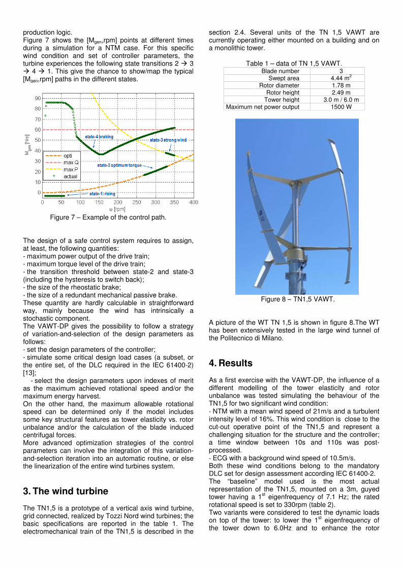
The wind turbine
The TN1,5 is a prototype of a vertical axis wind turbine, grid connected, realized by Tozzi Nord wind turbines; the basic specifications are reported in the table
tromechanical train of the TN1
the [Mgen,rpm
during a simulation for a NTM case. For this specific wind condition and set of controller parameters, the turbine experiences the following state transitions
This give the chance to show/map the typical paths in the different states.
7 – Example of the
The design of a safe control system requirethe following quantities:
aximum power output of the drive trainque level of the drive train
threshold between statethe hysteresis to switch back)
he size of the rheostatic brakehe size of a redundant mechanical passive brake
These quantity are hardly calculable in straightforward because the wind has intrinsically a
stochastic component. DP gives the possibility to follow a strategy
-selection of the design parameters as
gn parameters of the controller;imulate some critical design
the entire set, of the DLC required in the IEC 61400
elect the design parameters upon indexes of merit as the maximum achieved rotational s
energy harvest. On the other hand, the maximum allowablspeed can be determined only if the some key structural features as tower elasticity vs. rotor unbalance and/or the calculation of the
s. More advanced optimization strategies of the control parameters can involve the integration of this variation
selection iteration into an automatic routine, or else the linearization of the entire wind turbines system.
wind turbine
5 is a prototype of a vertical axis wind turbine, grid connected, realized by Tozzi Nord wind turbines; the basic specifications are reported in the table
tromechanical train of the TN1
,rpm] points at different times during a simulation for a NTM case. For this specific wind condition and set of controller parameters, the turbine experiences the following state transitions
This give the chance to show/map the typical paths in the different states.
Example of the control
The design of a safe control system requirethe following quantities:
aximum power output of the drive trainque level of the drive train;
threshold between statethe hysteresis to switch back);
he size of the rheostatic brake; he size of a redundant mechanical passive brake
These quantity are hardly calculable in straightforward se the wind has intrinsically a
the possibility to follow a strategy selection of the design parameters as
gn parameters of the controller;imulate some critical design load cases (a subset, or
the entire set, of the DLC required in the IEC 61400
elect the design parameters upon indexes of merit as the maximum achieved rotational speed and/or the
On the other hand, the maximum allowablspeed can be determined only if the some key structural features as tower elasticity vs. rotor unbalance and/or the calculation of the
More advanced optimization strategies of the control parameters can involve the integration of this variation
selection iteration into an automatic routine, or else the linearization of the entire wind turbines system.
5 is a prototype of a vertical axis wind turbine, grid connected, realized by Tozzi Nord wind turbines; the basic specifications are reported in the table
tromechanical train of the TN1,5 is described in the
] points at different times during a simulation for a NTM case. For this specific wind condition and set of controller parameters, the turbine experiences the following state transitions 2 �
This give the chance to show/map the typical
control path.
The design of a safe control system requires to assign
aximum power output of the drive train;
threshold between state-2 and state
he size of a redundant mechanical passive brake. These quantity are hardly calculable in straightforward
se the wind has intrinsically a
the possibility to follow a strategy selection of the design parameters as
gn parameters of the controller; load cases (a subset, or
the entire set, of the DLC required in the IEC 61400
elect the design parameters upon indexes of merit peed and/or the
On the other hand, the maximum allowable rotational speed can be determined only if the model includesome key structural features as tower elasticity vs. rotor unbalance and/or the calculation of the blade induced
More advanced optimization strategies of the control parameters can involve the integration of this variation
selection iteration into an automatic routine, or else the linearization of the entire wind turbines system.
5 is a prototype of a vertical axis wind turbine, grid connected, realized by Tozzi Nord wind turbines; the basic specifications are reported in the table 1. The
5 is described in the
] points at different times during a simulation for a NTM case. For this specific wind condition and set of controller parameters, the
� 3 This give the chance to show/map the typical
assign,
2 and state-3
These quantity are hardly calculable in straightforward se the wind has intrinsically a
the possibility to follow a strategy selection of the design parameters as
load cases (a subset, or the entire set, of the DLC required in the IEC 61400-2)
elect the design parameters upon indexes of merit peed and/or the
e rotational odel includes
some key structural features as tower elasticity vs. rotor blade induced
More advanced optimization strategies of the control parameters can involve the integration of this variation-
selection iteration into an automatic routine, or else
5 is a prototype of a vertical axis wind turbine, grid connected, realized by Tozzi Nord wind turbines; the
. The 5 is described in the
section currently operating a monolithic tower.
A picture of the WT TN 1has been extensively tested in the large wind tunnel of the Politecnico
4. As a first exercise withdifferent modelling of the tower elasticity and rotor unbalance was TN1,5 for - NTM with a mean wind speed of 21m/s and a turbulent intensity level of 16%. This wind condition is closecut-challenging situation for the structure and the controller; a time window between 10s and 110s was postprocessed.- ECG with a baBoth these wind conditions belong to the DLC set for design assessment according IEC 61400The “baseline” model representation of the TN1,5, mounted on a 3m, guyed tower having a 1rotational speed is set to 330rpm (table 2).Two variants were considered to on top of the tower: the tower down to 6.0Hz and
section 2.4. Several unitcurrently operating a monolithic tower.
Table 1
Maximum net
A picture of the WT TN 1has been extensively tested in the large wind tunnel of the Politecnico
Results
As a first exercise withdifferent modelling of the tower elasticity and rotor unbalance was TN1,5 for two significant wind condition:
NTM with a mean wind speed of 21m/s and a turbulent intensity level of 16%. This wind condition is close
-out operative point of the Tchallenging situation for the structure and the controller; a time window between 10s and 110s was postprocessed.
ECG with a baBoth these wind conditions belong to the DLC set for design assessment according IEC 61400The “baseline” model representation of the TN1,5, mounted on a 3m, guyed tower having a 1
tational speed is set to 330rpm (table 2).Two variants were considered to on top of the tower: the tower down to 6.0Hz and
Several unitscurrently operating either mounted on a building and on a monolithic tower.
Table 1 – data of TN 1Blade number
Swept areaRotor diameter
Rotor heightTower height
Maximum net power output
Figure 8 –
A picture of the WT TN 1,5 is shown in figure 8.The WT has been extensively tested in the large wind tunnel of the Politecnico di Milano.
As a first exercise with the VAWTdifferent modelling of the tower elasticity and rotor unbalance was tested simulating
two significant wind condition:NTM with a mean wind speed of 21m/s and a turbulent
intensity level of 16%. This wind condition is closeout operative point of the T
challenging situation for the structure and the controller; a time window between 10s and 110s was post
ECG with a background wind speed of 10.5m/s.Both these wind conditions belong to the DLC set for design assessment according IEC 61400The “baseline” model used representation of the TN1,5, mounted on a 3m, guyed tower having a 1
st eigenfrequency of 7.1 Hz; the rated
tational speed is set to 330rpm (table 2).Two variants were considered to on top of the tower: to lower the 1the tower down to 6.0Hz and
s of the TN 1mounted on a building and on
data of TN 1,5 VAWTBlade number
Swept area Rotor diameter
Rotor height Tower height 3.0power output
– TN1,5 VAWT
5 is shown in figure 8.The WT has been extensively tested in the large wind tunnel of
the VAWT-DP, the influence of different modelling of the tower elasticity and rotor
d simulating the behaviour of the two significant wind condition:
NTM with a mean wind speed of 21m/s and a turbulent intensity level of 16%. This wind condition is close
out operative point of the TN1,5 and represent a challenging situation for the structure and the controller; a time window between 10s and 110s was post
ckground wind speed of 10.5m/s.Both these wind conditions belong to the DLC set for design assessment according IEC 61400
used is the most representation of the TN1,5, mounted on a 3m, guyed
eigenfrequency of 7.1 Hz; the rated tational speed is set to 330rpm (table 2).
Two variants were considered to test the dynamic loads lower the 1
st eigenfrequency of
the tower down to 6.0Hz and to enhance the rotor
of the TN 1,5 VAWT are mounted on a building and on
5 VAWT. 3
4.44 m2
1.78 m 2.49 m
3.0 m / 6.0 m 1500 W
5 VAWT.
5 is shown in figure 8.The WT has been extensively tested in the large wind tunnel of
DP, the influence of different modelling of the tower elasticity and rotor
the behaviour of the two significant wind condition:
NTM with a mean wind speed of 21m/s and a turbulent intensity level of 16%. This wind condition is close to the
1,5 and represent a challenging situation for the structure and the controller; a time window between 10s and 110s was post
ckground wind speed of 10.5m/s. Both these wind conditions belong to the mandatory DLC set for design assessment according IEC 61400
is the most actualrepresentation of the TN1,5, mounted on a 3m, guyed
eigenfrequency of 7.1 Hz; the rated tational speed is set to 330rpm (table 2).
the dynamic loads eigenfrequency of
enhance the rotor
5 VAWT are mounted on a building and on
5 is shown in figure 8.The WT has been extensively tested in the large wind tunnel of
DP, the influence of a different modelling of the tower elasticity and rotor
the behaviour of the
NTM with a mean wind speed of 21m/s and a turbulent to the
1,5 and represent a challenging situation for the structure and the controller; a time window between 10s and 110s was post-
mandatory DLC set for design assessment according IEC 61400-2.
actual representation of the TN1,5, mounted on a 3m, guyed
eigenfrequency of 7.1 Hz; the rated
the dynamic loads eigenfrequency of
enhance the rotor
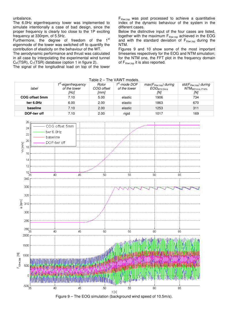
unbalance. The 6.0Hz eigenfrequency tower was implemented to simulate intentionally a case of bad design, since the proper frequency is clearly too close to the 1P exciting frequency at 330rpm, of 5.5Hz. Furthermore, the degree of freedom of the 1
st
eigenmode of the tower was switched off to quantify the contribution of elasticity on the behaviour of the WT. The aerodynamic performance and thrust was calculated in all case by interpolating the experimental wind tunnel CP(TSR), CT(TSR) database (option 1 in figure 2). The signal of the longitudinal load on top of the tower
FXtwr,top was post processed to achieve a quantitative index of the dynamic behaviour of the system in the different cases. Below the distinctive input of the four cases are listed, together with the maximum FXtwr,top achieved in the EOG and with the standard deviation of FXtwr,top during the NTM. Figures 9 and 10 show some of the most important timeseries respectively for the EOG and NTM simulation; for the NTM one, the FFT plot in the frequency domain of FXtwr,top it is also reported.
Table 2 – The VAWT models.
label 1
st-eigenfrequency of the tower
[Hz]
Rotor COG offset
[mm]
1st-mode DOF
of the tower
max(FXtwr,top) during EOGW10.5m/s
[N]
std(FXtwr,top) during NTMW21m/s,IT16%
[N]
COG offset 5mm 7.10 5.00 elastic 1906 734
twr 6.0Hz 6.00 2.00 elastic 1863 670
baseline 7.10 2.00 elastic 1253 311
DOF-twr off 7.10 2.00 rigid 1017 169
Figure 9 – The EOG simulation (background wind speed of 10.5m/s).
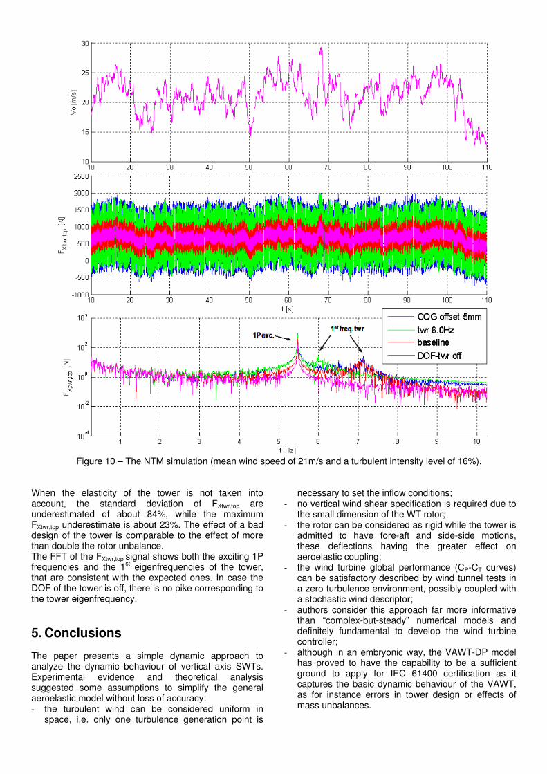
Figure 10 – The NTM simulation (mean wind speed of 21m/s and a turbulent intensity level of 16%).
When the elasticity of the tower is not taken into account, the standard deviation of FXtwr,top are underestimated of about 84%, while the maximum FXtwr,top underestimate is about 23%. The effect of a bad design of the tower is comparable to the effect of more than double the rotor unbalance. The FFT of the FXtwr,top signal shows both the exciting 1P frequencies and the 1
st eigenfrequencies of the tower,
that are consistent with the expected ones. In case the DOF of the tower is off, there is no pike corresponding to the tower eigenfrequency.
5. Conclusions The paper presents a simple dynamic approach to analyze the dynamic behaviour of vertical axis SWTs. Experimental evidence and theoretical analysis suggested some assumptions to simplify the general aeroelastic model without loss of accuracy: - the turbulent wind can be considered uniform in
space, i.e. only one turbulence generation point is
necessary to set the inflow conditions; - no vertical wind shear specification is required due to
the small dimension of the WT rotor; - the rotor can be considered as rigid while the tower is
admitted to have fore-aft and side-side motions, these deflections having the greater effect on aeroelastic coupling;
- the wind turbine global performance (CP-CT curves) can be satisfactory described by wind tunnel tests in a zero turbulence environment, possibly coupled with a stochastic wind descriptor;
- authors consider this approach far more informative than “complex-but-steady” numerical models and definitely fundamental to develop the wind turbine controller;
- although in an embryonic way, the VAWT-DP model has proved to have the capability to be a sufficient ground to apply for IEC 61400 certification as it captures the basic dynamic behaviour of the VAWT, as for instance errors in tower design or effects of mass unbalances.

Acknowledgments The authors would like to thank the Autonomous Province of Trento for its support with this project.
Nomenclature 1P 1-per-round exciting frequency = rpm/60 C Damping matrix [Ns/m] CP Power coefficient CT Thrust coefficient F Generalized forces vector [N] FXtwr,top Longitudinal force on top of the tower [N] GMi Generalized mass of the eigenmode [kg] ITOP IXX, IYY rotor moment of inertia [kgm
2]
IZZ Rotor polar moment of inertia [kgm2]
K Stiffness matrix [N/m] M Mass matrix [kg] MTOP Rotor mass [kg] MGEN Electrical generator torque [Nm] MROT Aerodynamic torque [Nm] P Power [W] T Torque [N] U Electric grid voltage [V] V Wind speed [m/s] e Rotor COG offset [m] f Electric grid frequency [s
-1]
ui Structural eigenmode x Streamwise coordinate [m] y Transversal coordinate [m] z Vertical coordinate [m]
δ Logarithmic decrement
θ Blade azimuthal angle [rad]
ω Rotational speed [rpm]
ωi Structural eigenfrequency [s-1
] Acronyms BEM Blade Element Momentum CFD Computational Fluid Dynamics COG Centre of gravity of the rotor DOF Degree of freedom DLC Design Load Case ECG Extreme Coherent Gust EOG Extreme Operating Gust FFT Fast Fourier Transform NTM Normal Turbulence Model SWT Small wind turbine TSR Tip Speed Ratio VAWT Vertical Axis Wind Turbine VAWT-DP Vertical Axis Wind Turbine Dynamic-Predictor WT Wind Turbine
References [1] Lobitz, D.W., Ashwill, T.D. Aerolastic Effects in the
Structural Dynamic Analysis of Vertical Axis Wind Turbines. Sandia Report SAND 85-0957, April 1986.
[2] Popelka, D. Aeroelastic Stability Analysis of a Darrieus Wind Turbine. Sandia Report SAND 82-0672, February 1982.
[3] Sutherland, H.J., Berg, D.E., Ashwill, D., Retrospective of VAWT Technology, SAND2012-0304, January 2012.
[4] Veers, P. S. Selected Papers on Wind Energy Technology, SAND90-1615, Sandia National Laboratories, Albuquerque, NM, January 1991.
[5] Homicz, G.F. Numerical Simulation of VAWT Stochastic Aerodynamic Loads Produced by Atmospheric Turbulence: VAWT-SAL Code. SAND91–1124 l UC–261, 1991.
[6] Veers, P. S. Modelling Stochastic Wind Loads on Vertical Axis Wind Turbines, Sandia National Laboratories Report SAND83-1909, September 1984.
[7] Anderson, M. B., Powles, S.J.R., Bossanyi, E. A. The Response of a Vertical Axis Wind Turbine to Fluctuating Aerodynamic Loads. 7th BWEA Conference, Oxford University, March 27–29, 1985.
[8] Malcolm, D.J. Modal Loading and Response of Darrieus Rotors in Turbulent Flow. 7
th Annual
VAWT Aerodynamics Seminar, held at Bushland, Texas, April 23-24, 1987.
[9] Ferreira, C.S, Van Bussel, G., Van Kuik, G. 2D CFD simulation of dynamic stall on a vertical axis wind turbine: verification and validation with PIV measurements, 45
th AIAA Aerospace Sciences
Meeting and Exhibit, 2007. [10] Machielse, L.A.H., Rieffe, H.Ch., Peeters, E.M.
Structural Vibration Frequencies and Drive Train Behaviour of 15 m VAWT. ECN-86-038, 1995.
[11] Bathe, K.J. Finite Element Procedures in Engineering Analysis. Prentice- Hall, Inc., 1982.
[12] Benfield, W.A., Hurda, R.E. Vibration Analysis of Structure by Component Mode Situation. AIAA J., Vol. 9, No. 7, July 1971.
[13] International Standard IEC 61400-2. Wind turbines – Part 2: Design requirements for small wind turbines. Second edition, 2006.
[14] Veers, P.S. Three-Dimensional Wind Simulation. Sandia National Laboratories Report SAND884152, March 1988.
[15] Battisti L., Zanne L., Dell’Anna S., Dossena V., Persico G., Paradiso B. Aerodynamic Measurements on a Vertical Axis Wind Turbine in a Large Scale Wind Tunnel”. Journal of Energy Resources Technology, Volume 133, Issue 3, September 2011.
[16] Battisti, L., Brighenti, A., Zanne, L. Analisi dell’effetto della scelta dell’architettura palare sulle prestazioni di turbine eoliche ad asse verticale. Proceedings of ATI, L'Aquila (Italy) 7-11 September 2009.
[17] Battisti, L. Gli Impianti Motori Eolici, Ed. Green Place Energies, www.greenplaceenergies.com, 2011.
[18] Strickland, J. The Darrieus Turbine: A Performance Prediction Model Using Multiple Stream tubes. SAND75-0431,1975.
[19] Hansen, M.O.L. Aerodynamics of Wind Turbines 2nd
ed. Earthscan: London, 2008.
[20] Risø. Guidelines for Design of Wind Turbines. 2nd
Edition. Copenhagen: Det Norske Veritas/Risø, 2002.
[21] EN 1991 – 1.4. The Eurocode 1: Wind actions Part 1-4, 1991.